US7628506B2 - Modular light fixture with power pack and radiative, conductive, and convective cooling - Google Patents
Modular light fixture with power pack and radiative, conductive, and convective coolingDownload PDFInfo
- Publication number
- US7628506B2 US7628506B2US11/771,370US77137007AUS7628506B2US 7628506 B2US7628506 B2US 7628506B2US 77137007 AUS77137007 AUS 77137007AUS 7628506 B2US7628506 B2US 7628506B2
- Authority
- US
- United States
- Prior art keywords
- ballast
- power pack
- light fixture
- raceway
- cover
- Prior art date
- Legal status (The legal status is an assumption and is not a legal conclusion. Google has not performed a legal analysis and makes no representation as to the accuracy of the status listed.)
- Expired - Fee Related, expires
Links
Images


Classifications
- F—MECHANICAL ENGINEERING; LIGHTING; HEATING; WEAPONS; BLASTING
- F21—LIGHTING
- F21V—FUNCTIONAL FEATURES OR DETAILS OF LIGHTING DEVICES OR SYSTEMS THEREOF; STRUCTURAL COMBINATIONS OF LIGHTING DEVICES WITH OTHER ARTICLES, NOT OTHERWISE PROVIDED FOR
- F21V29/00—Protecting lighting devices from thermal damage; Cooling or heating arrangements specially adapted for lighting devices or systems
- F21V29/50—Cooling arrangements
- F21V29/70—Cooling arrangements characterised by passive heat-dissipating elements, e.g. heat-sinks
- F21V29/83—Cooling arrangements characterised by passive heat-dissipating elements, e.g. heat-sinks the elements having apertures, ducts or channels, e.g. heat radiation holes
- F—MECHANICAL ENGINEERING; LIGHTING; HEATING; WEAPONS; BLASTING
- F21—LIGHTING
- F21S—NON-PORTABLE LIGHTING DEVICES; SYSTEMS THEREOF; VEHICLE LIGHTING DEVICES SPECIALLY ADAPTED FOR VEHICLE EXTERIORS
- F21S8/00—Lighting devices intended for fixed installation
- F21S8/04—Lighting devices intended for fixed installation intended only for mounting on a ceiling or the like overhead structures
- F21S8/06—Lighting devices intended for fixed installation intended only for mounting on a ceiling or the like overhead structures by suspension
- F—MECHANICAL ENGINEERING; LIGHTING; HEATING; WEAPONS; BLASTING
- F21—LIGHTING
- F21V—FUNCTIONAL FEATURES OR DETAILS OF LIGHTING DEVICES OR SYSTEMS THEREOF; STRUCTURAL COMBINATIONS OF LIGHTING DEVICES WITH OTHER ARTICLES, NOT OTHERWISE PROVIDED FOR
- F21V23/00—Arrangement of electric circuit elements in or on lighting devices
- F21V23/003—Arrangement of electric circuit elements in or on lighting devices the elements being electronics drivers or controllers for operating the light source, e.g. for a LED array
- F21V23/007—Arrangement of electric circuit elements in or on lighting devices the elements being electronics drivers or controllers for operating the light source, e.g. for a LED array enclosed in a casing
- F21V23/008—Arrangement of electric circuit elements in or on lighting devices the elements being electronics drivers or controllers for operating the light source, e.g. for a LED array enclosed in a casing the casing being outside the housing of the lighting device
- F—MECHANICAL ENGINEERING; LIGHTING; HEATING; WEAPONS; BLASTING
- F21—LIGHTING
- F21V—FUNCTIONAL FEATURES OR DETAILS OF LIGHTING DEVICES OR SYSTEMS THEREOF; STRUCTURAL COMBINATIONS OF LIGHTING DEVICES WITH OTHER ARTICLES, NOT OTHERWISE PROVIDED FOR
- F21V23/00—Arrangement of electric circuit elements in or on lighting devices
- F21V23/02—Arrangement of electric circuit elements in or on lighting devices the elements being transformers, impedances or power supply units, e.g. a transformer with a rectifier
- F21V23/026—Fastening of transformers or ballasts
- F—MECHANICAL ENGINEERING; LIGHTING; HEATING; WEAPONS; BLASTING
- F21—LIGHTING
- F21V—FUNCTIONAL FEATURES OR DETAILS OF LIGHTING DEVICES OR SYSTEMS THEREOF; STRUCTURAL COMBINATIONS OF LIGHTING DEVICES WITH OTHER ARTICLES, NOT OTHERWISE PROVIDED FOR
- F21V29/00—Protecting lighting devices from thermal damage; Cooling or heating arrangements specially adapted for lighting devices or systems
- F21V29/50—Cooling arrangements
- F21V29/502—Cooling arrangements characterised by the adaptation for cooling of specific components
- F21V29/508—Cooling arrangements characterised by the adaptation for cooling of specific components of electrical circuits
- F—MECHANICAL ENGINEERING; LIGHTING; HEATING; WEAPONS; BLASTING
- F21—LIGHTING
- F21V—FUNCTIONAL FEATURES OR DETAILS OF LIGHTING DEVICES OR SYSTEMS THEREOF; STRUCTURAL COMBINATIONS OF LIGHTING DEVICES WITH OTHER ARTICLES, NOT OTHERWISE PROVIDED FOR
- F21V23/00—Arrangement of electric circuit elements in or on lighting devices
- F21V23/04—Arrangement of electric circuit elements in or on lighting devices the elements being switches
- F21V23/0442—Arrangement of electric circuit elements in or on lighting devices the elements being switches activated by means of a sensor, e.g. motion or photodetectors
- F—MECHANICAL ENGINEERING; LIGHTING; HEATING; WEAPONS; BLASTING
- F21—LIGHTING
- F21V—FUNCTIONAL FEATURES OR DETAILS OF LIGHTING DEVICES OR SYSTEMS THEREOF; STRUCTURAL COMBINATIONS OF LIGHTING DEVICES WITH OTHER ARTICLES, NOT OTHERWISE PROVIDED FOR
- F21V23/00—Arrangement of electric circuit elements in or on lighting devices
- F21V23/06—Arrangement of electric circuit elements in or on lighting devices the elements being coupling devices, e.g. connectors
- F—MECHANICAL ENGINEERING; LIGHTING; HEATING; WEAPONS; BLASTING
- F21—LIGHTING
- F21V—FUNCTIONAL FEATURES OR DETAILS OF LIGHTING DEVICES OR SYSTEMS THEREOF; STRUCTURAL COMBINATIONS OF LIGHTING DEVICES WITH OTHER ARTICLES, NOT OTHERWISE PROVIDED FOR
- F21V25/00—Safety devices structurally associated with lighting devices
- F21V25/02—Safety devices structurally associated with lighting devices coming into action when lighting device is disturbed, dismounted, or broken
- F—MECHANICAL ENGINEERING; LIGHTING; HEATING; WEAPONS; BLASTING
- F21—LIGHTING
- F21Y—INDEXING SCHEME ASSOCIATED WITH SUBCLASSES F21K, F21L, F21S and F21V, RELATING TO THE FORM OR THE KIND OF THE LIGHT SOURCES OR OF THE COLOUR OF THE LIGHT EMITTED
- F21Y2103/00—Elongate light sources, e.g. fluorescent tubes
- F—MECHANICAL ENGINEERING; LIGHTING; HEATING; WEAPONS; BLASTING
- F21—LIGHTING
- F21Y—INDEXING SCHEME ASSOCIATED WITH SUBCLASSES F21K, F21L, F21S and F21V, RELATING TO THE FORM OR THE KIND OF THE LIGHT SOURCES OR OF THE COLOUR OF THE LIGHT EMITTED
- F21Y2113/00—Combination of light sources
Definitions
- the subject of the disclosurerelates generally to energy management and utilization in large commercial buildings, and more particularly to a modular light fixture apparatus including radiative, conductive, and/or convective cooling.
- ballastdetermines, for example, the power consumption and optimal type of lamp to be used in the fixture.
- the choice of ballast and lamplargely determine the gross light production, expected maintenance interval, and energy consumption of the fixture. Consequently, effective lighting redeployment may require changing the ballast and/or type of lamp used in the fixture.
- the ballastis generally hard-wired within the light fixture, and the light fixture is hard-wired to a building power supply.
- any maintenance and/or repairs to the light fixturemay require the costly services of an electrician.
- itcan be expensive to move, replace, and/or modify an existing light fixture.
- existing light fixturestend to remain in place even when they are obsolete or lighting requirements change, resulting in wasted electrical power and lost productivity due to ineffective lighting.
- a light fixturewhich includes a detachable power pack such that the ballasts and other lighting components can be quickly replaced to achieve maximized energy savings.
- a first power pack including a ballast with a ballast factor of 1.0may be replaced by a second power pack including a ballast with a ballast factor of 0.75 to reduce power consumption of the light fixture.
- a detachable power pack with latching endssuch that the detachable power pack can be securely mounted to and easily detached from the light fixture without the use of tools.
- ballasts used to supply power to light bulbscan produce a substantial amount of heat. This heat is mostly generated by metal-oxide semiconductor field-effect transistors (MOSFETs) and other electrical components within the ballast.
- MOSFETsmetal-oxide semiconductor field-effect transistors
- traditional light fixturesare limited in their ability to disperse the heat generated by ballasts. As a result, the entire light fixture can become hot and the risk of fire due to ballast overheating is increased.
- operating a ballast at an elevated temperaturedecreases the operating lifetime of the ballast, resulting in increased costs to replace ballasts.
- high temperature operationresults in less light energy output because light output is lower when the ballast components and lamps are hot.
- heat generated by the ballastscan be dispersed through convective, conductive, and/or radiative cooling.
- An exemplary light fixtureincludes a lampholder mounted to a raceway, where the lampholder is electrically connected to a lampholder connector.
- a power packincludes a power pack cover and a ballast.
- An outer surface of the power pack coverincludes an emissive coating such that heat generated by the ballast is emitted from the power pack cover.
- the ballastis mounted in direct contact with the power pack cover such that the heat generated by the ballast is conducted from the ballast to the power pack cover.
- the ballastincludes a power input connector adapted to electrically connect to a power cord and a ballast output connector adapted to electrically connect to the lampholder connector.
- An exemplary power pack for a light fixtureincludes a power pack cover.
- An outer surface of the power pack coverincludes an emissive coating such that heat generated by a ballast is emitted from the power pack cover.
- the ballastis mounted in direct contact with the power pack cover such that the heat generated by the ballast is conducted from the ballast to the power pack cover.
- a power input connectoris mounted to the ballast and is adapted to electrically connect to a power cord.
- a ballast output connectoris mounted to the ballast and is adapted to electrically connect to a lampholder connector.
- An exemplary method of dispersing heat from a light fixtureincludes mounting a ballast in direct contact with a power pack cover such that heat generated by the ballast is conducted from the ballast to the power pack cover.
- the ballastincludes a power input connector adapted to electrically connect to a power cord and a ballast output connector adapted to electrically connect to a lampholder connector.
- An emissive coatingis applied to an outer surface of the power pack cover such that the heat generated by the ballast is emitted from the power pack cover.
- the power pack coveris mounted to a light fixture.
- An exemplary light fixtureincludes a lampholder electrically connected to a lampholder connector.
- a power packincludes a ballast and a power pack cover which extends over the ballast.
- the ballastincludes a power input connector adapted to electrically connect to a power cord and a ballast output connector adapted to electrically connect to the lampholder connector.
- the racewayis mounted to the power pack cover and the lampholder, and includes an aperture such that heat generated by the ballast is dispersed through the aperture.
- Another exemplary light fixtureincludes a light reflecting sheet, where an upper surface of the light reflecting sheet forms a valley.
- a lampholderis mounted to a raceway and is electrically connected to a lampholder connector.
- a power packis mounted over at least a portion of the valley and includes a ballast and a power pack cover extending over the ballast.
- the ballastincludes a power input connector adapted to electrically connect to a power cord and a ballast output connector adapted to electrically connect to the lampholder connector.
- a cover plateis mounted adjacent to an end of the valley. The cover plate includes an aperture such that heat generated by the ballast is dispersed through the aperture.
- An exemplary method of dispersing heat from a modular light fixtureincludes mounting a power pack over at least a portion of a valley formed by an upper surface of a light reflecting sheet.
- the power packincludes a power pack cover and a ballast mounted to the power pack cover.
- the ballastincludes a power input connector adapted to electrically connect to a power cord and a ballast output connector adapted to electrically connect to a lampholder connector.
- a first cover plateis mounted adjacent to a first end of the valley, where the first cover plate includes a first aperture.
- a second cover plateis mounted adjacent to a second end of the valley, where the second cover plate includes a second aperture. Air circulated through the first aperture and the second aperture disperses heat generated by the ballast.
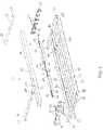
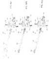
- FIG. 1is an exploded perspective view of a light fixture in accordance with an exemplary embodiment.
- FIG. 2is an assembled perspective view of the light fixture of FIG. 1 in accordance with an exemplary embodiment.
- FIG. 3is an end view of the light fixture of FIG. 1 in accordance with an exemplary embodiment.
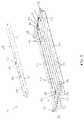
- FIG. 4is a perspective view from below the light fixture of FIG. 1 , with a detachable power pack separated from the body of the light fixture in accordance with an exemplary embodiment.
- FIG. 5is a perspective view from the side of the light fixture of FIG. 1 , with the detachable power pack separated from the body of the light fixture in accordance with an exemplary embodiment.
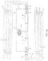
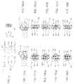
- FIGS. 6( a )- 6 ( c )are circuit diagrams in accordance with exemplary embodiments for light fixtures having detachable ballast assemblies with hard-wired, armored whip, and modular connector input power configurations, respectively.
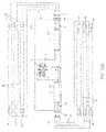
- FIGS. 7( a )- 7 ( e )are circuit diagrams in accordance with exemplary embodiments for light fixtures having detachable ballast assemblies with normal ballast factor, low ballast factor, high ballast factor, dual switch/high ballast factor, and battery backup/high ballast factor configurations, respectively.
- FIGS. 8( a )- 8 ( c )are perspective views of exemplary modular power supply cords.
- FIG. 9presents plan views of the components of exemplary power input wiring.
- FIGS. 10( a )- 10 ( j )show exemplary pin assignments for the input power plug and socket connectors in various configurations.
- FIG. 11is a block diagram of a controller and related components of a light fixture in accordance with an exemplary embodiment.
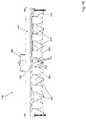
- FIG. 12is a perspective view of a modular light fixture with convective cooling in accordance with an exemplary embodiment.
- FIG. 13is a partial view of the modular light fixture of FIG. 12 illustrating a convective endplate in accordance with an exemplary embodiment.
- FIG. 14is a partial view of a power pack cover illustrating a latching end opening in accordance with an exemplary embodiment.
- FIG. 15is a partial view of a raceway illustrating a raceway opening in accordance with an exemplary embodiment.
- FIG. 16is an end view of the modular light fixture of FIG. 12 illustrating a convective cover plate in accordance with an exemplary embodiment.
- FIG. 17is a cross-sectional view of a ballast mounted to a power pack such that radiative cooling occurs in accordance with an exemplary embodiment.
- FIG. 18is a perspective view of a collapsible radiator in accordance with an exemplary embodiment.
- FIG. 19Ais a partial side view of a power pack cover including a first side slot in accordance with an exemplary embodiment.
- FIG. 19Bis a partial top view of a power pack cover including a first top slot and a second top slot in accordance with an exemplary embodiment.
- FIG. 19Cis a cross-sectional view of a collapsible radiator and a power pack cover in accordance with an exemplary embodiment.
- FIG. 20Ais a cross-sectional view illustrating a collapsible radiator in a collapsed state and mounted to a power pack cover in accordance with an exemplary embodiment.
- FIG. 20Bis a cross-sectional view illustrating a collapsible radiator in a partially expanded state and mounted to a power pack cover in accordance with an exemplary embodiment.
- FIGS. 1-5show various views of a fluorescent tube light fixture 10 for use in a method and apparatus according to an exemplary embodiment.
- the fixture 10includes a fixture body 66 and a detachable power pack 64 .
- the fixture body 66includes a pair of raceways 12 connected by a ballast channel 14 to form a generally I-frame configuration.
- Each raceway 12may be enclosed with a raceway cover 16 , so that the raceway 12 and raceway cover 16 together form a raceway channel 18 , as shown in FIGS. 2-3 .
- Each end of each raceway 12may include a suspension point 68 , for suspending the light fixture 10 above an area to be illuminated, for example using one or more chains connected between the suspension points 68 and the ceiling.
- the suspension points 68may be located at or near the corners of the fixture, to ensure that the suspension hardware does not interfere with maintenance of the light fixture including, but not limited to, replacement of the detachable power pack 64 .
- Each light reflector 22is secured to each of the raceways 12 such as by rivets, bolts, screws or the like. Six reflectors are shown in the drawings, however, it should be noted that any number of light reflectors can be used.
- Each light reflector 22can be fabricated from a single piece of material or can be fabricated of individual pieces of material. Any exposed edges of the light reflectors 22 may be folded back (hemmed) to reduce sharp edges and improve safety.
- each light reflector 22defines a reflector channel 24 adapted to house a lamp 30 (not shown in FIGS. 1-5 ).
- lamp 30is a fluorescent tube lamp.
- a metal halide lamp, a sodium lamp, or any other type of discharge lamp known to those of skill in the artcan be used.
- the fixture body 66includes lampholder harnesses 26 housed in the two raceway channels 18 at the opposite ends of the light fixture.
- Each lampholder harness 26includes one or more lampholders (sockets) 28 and a lampholder harness connector 32 .
- Each lampholder 28may extend through a corresponding aperture 34 in a raceway 12 adjacent to the end of a reflector channel 24 .
- a single fluorescent tube lampextends between a pair of lampholders 28 at opposite ends of each reflector channel 24 .
- the detachable power pack 64 of the light fixture 10may include a ballast channel cover 36 , one or more ballasts 48 , power input wiring 54 , a modular power input connector 56 , ballast output wiring 58 , and a modular ballast output connector 60 .
- the detachable power pack 64may be detachable from the light fixture body 66 without the use of tools, and without any interference from the suspension hardware.
- the ballast channel cover 36 of the detachable power pack 64engages the ballast channel 14 of the fixture body 66 to define a ballast chamber 38 .
- the ballast channel cover 36can include cover clip portions 41 which mate with corresponding body clip portions 40 to detachably attach the ballast channel cover 36 to the ballast channel 14 .
- the clipsprovide an interference or frictional fit to allow separation without the use of tools. However, this is not required, and other means, such as screws, could be used to detachably attach the detachable power pack 64 to the fixture body 66 .
- detachable power pack 64can include latching ends (or flanges) adapted to mate with apertures in the raceways 12 . The latching ends are described in more detail with reference to FIGS. 12-15 .
- the ballast channel covermay include a power line connector aperture 42 adapted to receive a modular power input connector 56 , and a feature connector aperture 43 adapted to receive a feature connector (not shown).
- the modular power input connector 56may be a polarized modular power input socket 210 configured for the available electrical power supply voltage and configuration, as discussed in more detail below with reference to FIGS. 9-10 . However, this is not required, and other methods can be used to supply electrical power to the fixture, as discussed in more detail below with reference to FIGS. 6( a )- 6 ( c ).
- the exemplary detachable power pack 64 of the light fixture 10includes two ballasts 48 , for example a model 49776 electronic ballast available from GE Lighting of Cleveland, Ohio. However, this is not required, and other makes and models of ballasts can be employed. Further, while the exemplary light fixture 10 includes two ballasts 48 , a greater or lesser number of ballasts 48 can be used.
- Each ballast 48has a first (input) end 50 and a second (output) end 52 .
- Power input wiring 54electrically connects the modular power input connector 56 to the first end 50 of each ballast 48 .
- the modular power input connector 56mates with a modular power cord assembly 180 supplying electrical power.
- the modular power cord assembly 180may be quickly and easily disconnected from the modular power input connector 56 without the use of tools, in order to verifiably and positively remove electrical power from the fixture to reduce the risk of electrical shock during maintenance.
- Ballast output wiring 58electrically connects the second (output) end 52 of each ballast 48 to a modular ballast output connector 60 .
- the modular ballast output connector 60mates with a corresponding lampholder harness connector 32 .
- the modular ballast output connector 60may be quickly and easily disconnected from the lampholder harness connector 32 without the use of tools.
- Each ballast 48is fastened to the ballast channel cover 36 , for example using threaded fasteners, to engage mounting ears 62 on each ballast 48 through holes in the ballast channel cover 36 .
- threaded fastenersare not required and other means can be utilized to fasten each ballast 48 to the ballast channel cover 36 , such as adhesives or interference mounting techniques.
- the modular power input connector 56may extend through the aperture 42 for connection to a modular power cord assembly 180 (not shown in FIGS. 1-5 ).
- the ballast channel cover 36is positioned above the ballast 48 , with good thermal contact between the ballast 48 and ballast channel cover 36 , so waste heat generated by the ballast 48 conducts upwardly to the ballast channel cover 36 .
- the ballast channel cover 36is positioned at the top of the fixture 10 , and exposed to air circulation so waste heat from the ballast can convect and radiate away from the light fixture.
- each ballast 48when the detachable power pack is attached to the fixture body 66 , each ballast 48 is housed in the ballast chamber 38 , and oriented so that the modular ballast output connectors 60 of the power pack 46 can mate with the modular lampholder harness connectors 32 of the lampholder harnesses 26 .
- the ballasts 48are electrically connected to deliver power to the lampholder harnesses 26 , the lampholders 28 , and the lamps 30 (not shown in FIGS. 1-5 ).
- Suitable mating modular ballast output connectors 60 and modular lampholder harness connectors 32are a male and female connector pair available as models 231-604 and 231-104/02600 from Wago Corp. of Germantown, Wis. However, this is not required and other types, makes and models of mating modular connectors can be used.
- FIGS. 4 and 5are perspective views of the light fixture of FIG. 1 , with the detachable power pack 64 separated from the fixture body 66 of the light fixture 10 .
- the following discussion of exemplary methods for modifying or servicing a light fixtureis not meant to be limiting as alternative methods may be used.
- Replacing the detachable power pack 64 in a light fixture 10is straightforward and does not necessarily require a high level of skill or the use of tools.
- the modular power cord 180is disconnected from the modular power input connector 56 , thereby positively and verifiably cutting off electrical power from the light fixture 10 to improve the safety of the procedure.
- the old detachable power pack 64is separated from the body 66 of the light fixture by uncoupling the cover clip portions 41 from the body clip portions 40 , and by disconnecting the modular ballast output connectors 60 from their corresponding lampholder harness connectors 32 .
- the old power pack 64can be set aside for eventual repair, recycling, or disposal.
- ballast output connectors 60 on the new power pack 64are mated with their corresponding lampholder harness connectors 32 , and the new power pack 64 is detachably fastened to the body 66 of the light fixture by coupling the cover clip portions 41 with the body clip portions 40 .
- Modular power cord 180is reconnected to the modular power input connector 56 to restore power to the light fixture 10 for normal operation.
- detachable power packcan be used with other light fixtures, and is not meant to be limited to use with the light fixture shown and described herein.
- another fluorescent tube light fixture embodiment in which the detachable power pack can be employedis that shown and described in U.S. Pat. No. 6,585,396, the entire contents of which are hereby incorporated by reference.
- FIGS. 6( a )- 6 ( c )are circuit diagrams for light fixtures having detachable ballast assemblies with alternative input power configurations in accordance with exemplary embodiments.
- a variety of alternative input power configurationscan be provided to allow a light fixture to be used with a variety of available power sources. These alternative input power configurations can be classified generally into “hard wire” configurations, and “modular” configurations.
- a light fixture according to an exemplary embodimentcan include either input power configuration.
- FIGS. 6( a ) and 6 ( b )show examples of hard wire input power configurations.
- the detachable power pack 64 of FIG. 6( a )includes a hard wire power supply connector 152 .
- the hard wire power supply connector 152represents a connection which is hard wired directly to a branch circuit in the building, for example by an electrician.
- the detachable power pack 64 of FIG. 6( b )includes one type of hard wire power supply connector, an armored whip power supply line 154 .
- the detachable power pack 64 of FIG. 6( c )includes a modular wiring system power supply line 156 .
- An alternative, “daisy chain” modular wiring system power supply lineis described, for example, in U.S. Pat. No. 6,746,274, the entire contents of which are hereby incorporated by reference.
- FIGS. 6( a )- 6 ( c )show specific combinations of input power configurations with particular types of ballasts, these specific combinations are not required. It should be understood that any of these input power configurations can be used with a light fixture based on the environment in which the light fixture is to be installed. It should also be understood that any of these power supply configurations can be used with any type of ballast, not just the particular types of ballasts shown in FIGS. 6( a )- 6 ( c ).
- FIGS. 7( a )- 7 ( e )are circuit diagrams for light fixtures having detachable ballast assemblies with alternative ballast configurations in accordance with exemplary embodiments.
- a variety of alternative ballast configurationscan allow a light fixture to provide a wider variety of light levels at varying power consumption levels.
- the detachable power pack of FIG. 7( a )is a high ballast factor detachable power pack 160 that includes a high ballast factor ballast 162 .
- the detachable power pack of FIG. 7( b )is a normal ballast factor detachable power pack 164 that includes a normal ballast factor ballast 166 .
- the detachable power pack of FIG. 7( c )is a low ballast factor detachable power pack 168 that includes a low ballast factor ballast 170 .
- the detachable power pack of FIG. 7( d )is a dual switched detachable power pack 172 that includes two high ballast factor ballasts 162 that receive independent power on separate lines from the modular power input connector 56 .
- the detachable power pack of FIG. 7( e )is a battery backup detachable power pack 174 that includes battery backup circuitry 176 , a battery backup ballast 178 , and two high ballast factor ballasts 162 .
- the battery backup ballast 178can supply lighting in the event of a failure of the main electrical supply, for example in the case of a natural disaster or fire.
- FIG. 8( a )shows a modular power cord assembly 180 having a first end that terminates in a polarized modular power supply plug, and a second end that terminates in a conventional power plug 182 .
- the modular power cord assembly 180includes a suitable length of conventional insulated power cord 181 with 3 or 4 insulated conductors surrounded by an insulated jacket.
- the power cord 181can be any standard electrical power cord having suitable power handling and other specifications for example 18 gauge 3-conductor or 18 gauge 4-conductor power cord can be used.
- cord lengthsfor example from 3′ to 35′ in length, are kept in stock, allowing the appropriate cord length to be chosen from stock at the time the light fixture is installed, without requiring any delay for custom manufacturing of a modular power supply cord having the appropriate length.
- the polarized modular power supply plugis preferably a 6-pin “Mate-N-Lock” plug connector of the type sold by the AMP division of Tyco Electronics of Harrisburg, Pa. However, this is not required and other types, makes and models of modular power supply connectors can be used.
- the polarized modular power supply plugpreferably includes strain relief, for example two strain relief pieces 184 and a plastic insert 185 (such a AMP P/N 640715-1), and a plug body 188 .
- the strain relief 184 , plastic insert 185 , and plug body 188can be held together with screws 186 , such as #6 ⁇ 5 ⁇ 8′′ sheet metal screws.
- the plug body 188has six positions for holding electrical pins, although a plug body having a greater or lesser number of pin positions can be used. A short portion of the insulation is stripped from the end of each conductor in the electrical cord 181 , and an electrical pin is electrically and mechanically connected to the stripped portion. The electrical pins and attached conductors are then inserted into specific pin positions in the plug body 188 to form a polarized modular power supply plug, as discussed in more detail with reference to FIGS. 10( a )- 10 ( j ).
- the “extra long” electrical pin 190 used for the green (safety ground) lineis generally slightly longer than the “standard length” electrical pins 192 used for the black (power supply or “hot”), white (power return or neutral), and red (switched power) lines. This helps ensure that the safety ground connection is made first and broken last when the plug 158 is inserted into or removed from its corresponding socket.
- a suitable extra long electrical pin 190 for the safety groundwould be AMP PN 350669, and a suitable standard length electrical pin 192 for the other lines would be AMP PN 350547-1.
- the conventional power plug 182can be any standard electrical plug configuration, such as a NEMA 5, NEMA L5, NEMA L7, NEMA 6, or NEMA L6 plug.
- a variety of plug configurationsare kept in stock, allowing the appropriate plug configuration to be chosen from stock at the time the light fixture is installed, without requiring any delay for custom manufacturing of a modular power supply cord having the appropriate plug configuration.
- FIG. 8( b )shows an alternative modular power cord assembly 198 having a first end that terminates in a polarized modular power supply plug, and a second end that terminates in stripped conductors 196 .
- the stripped conductorsmay be about 3 ⁇ 8′′ in length.
- the modular power cord assembly 198is similar in construction to the modular power cord assembly 180 , except that the modular power cord assembly 198 terminates in stripped conductors 196 that can be used, for example, to hardwire the fixture to building power, and the modular power cord assembly 198 is wired for “universal” application.
- FIG. 8( c )shows a “dual switch” modular power cord assembly 199 that is otherwise similar in construction to the modular power cord assembly 198 .
- FIG. 9shows exemplary power input wiring 54 for a detachable power pack in a light fixture in accordance with an exemplary embodiment.
- the exemplary power input wiring 54includes at least 3 insulated conductors, including a safety ground (green) wire 200 , a power return (white) wire 202 , and a power supply (black) wire 204 .
- the power input wiring 54may also include a switched power (red) wire 206 , and a second power supply (black) wire 204 .
- Each conductoris made of a suitable length of insulated wire, for example UL 1015 18 AWG wire rated for 105° C. and 600V can be used.
- a modular power input connector 56which may be a polarized modular power input socket 210 such as a 6-pin “Mate-N-Lock” socket connector of the type sold by the AMP division of Tyco Electronics of Harrisburg, Pa.
- the polarized modular power input socket 210includes a socket body 208 having six positions for holding single conductor sockets, although a socket having a greater or lesser number of single conductor socket positions could be used.
- a short portion of the insulationis stripped from the end of each conductor, and a single conductor socket 193 , for example AMP PN 350550-1, is electrically and mechanically connected to the stripped portion, for example by crimping and/or soldering.
- the single conductor socket 193 and attached conductorare then inserted into a specific single conductor socket position in the socket body 208 to form the polarized modular power socket 210 , as discussed in more detail with reference to FIGS. 10( a )- 10 ( j ).
- FIGS. 10( a )- 10 ( j )show exemplary pin assignments for the input power plug and socket connectors in various configurations of a detachable power pack for use in a light fixture. However, these pin assignments are not required, and other pin assignments could be used.
- FIGS. 10( a ) and 10 ( b )illustrate a convention for numbering the pins ( 1 - 6 ) in the input power plug and socket connectors.
- FIGS. 10( c ) and 10 ( d )illustrate an exemplary 120V power supply configuration.
- the exemplary 120V power supply configurationuses a 120V modular power supply plug 212 along with a 120V modular power input socket 220 .
- the plug 212 and socket 220each include at least a safety ground (green) wire 200 , a power return (white) wire 202 , and a power supply (black) wire 204 located at specific positions in plug head 188 and socket head 208 , respectively.
- the plug 212 and socket 220also include a second power (red) wire 206 .
- FIGS. 10( e ) and 10 ( f )illustrate an exemplary 277V power supply configuration.
- the exemplary 277V power supply configurationuses a 277V modular power supply plug 214 along with a 277V modular power input socket 222 .
- the 277V plug 214 and the 277V socket 222each include at least a safety ground (green) wire 200 , a power return (white) wire 202 , and a power supply (black) wire 204 .
- the safety ground (green) wire 200 and the power return (white) wire 202 of the 277V configurationare at the same pin positions as in the 120V configuration, however the power supply (black) wire 204 is at a different pin position.
- the plug 214 and socket 222also include a second or switched power (red) wire 206 .
- FIGS. 10( g ) and 10 ( h )illustrate an exemplary 347/480 V power supply configuration.
- the exemplary 347/480V power supply configurationuses a 347/480V modular power supply plug 216 along with a 347/480V modular power input socket 224 .
- the 347/480V plug 216 and the 347/480V socket 224each include at least a safety ground (green) wire 200 , a power return (white) wire 202 , and a power supply (black) wire 204 .
- the safety ground (green) wire 200 and the power return (white) wire 202 of the 277V configurationare at the same pin positions as in the 120V and 277V configurations, however the power supply (black) wire 204 is at a different pin position.
- the plug 216 and socket 224When used in a 347/480V dual-switched configuration, the plug 216 and socket 224 also include a second or switched power (red) wire 206 .
- FIGS. 10( i ) and 10 ( j )illustrate an exemplary “UNV” or “universal” power supply configuration.
- the exemplary “UNV” or “universal” power supply configurationuses a UNV modular power supply plug 218 along with a UNV modular power input socket 226 .
- a light fixture wired with the UNV power supply socket configurationcan be used with either a 120V supply cord or a 277V supply cord.
- a light fixture wired with the 120 v power supply socket configurationcan be used with either a 120V supply cord or a UNV supply cord.
- a light fixture wired with the 277 v power supply socket configurationcan be used with either a 277V supply cord or a UNV supply cord.
- the UNV plug 218 and the UNV socket 226each include at least a safety ground (green) wire 200 and a power return (white) wire 202 , in the same pin and socket positions as the 120V, 277V, and 347/480V configurations.
- the UNV plug 218 and the UNV socket 226each include two power supply (black) wires 204 , one power supply (black) wire 204 at each of the two pin positions used for the power supply (black) wire 204 in the 120V and 277V configurations.
- the plug 218 and socket 226When used in a 120V or 277V dual-switched configuration, the plug 218 and socket 226 also include a second or switched power (red) wire 206 .
- a modular light fixturecan include a controller 80 , for example a microprocessor or microcontroller as known in the art.
- the controller 80may include suitable non-volatile program memory, for example read-only memory (ROM) such as an electrically programmable read only memory (EPROM or EEPROM).
- ROMread-only memory
- EPROMelectrically programmable read only memory
- EEPROMelectrically programmable read only memory
- the controller 80may also include suitable random access memory, for storage of dynamic state variables such as environmental signals and current day/time.
- the light fixtureincludes a power source 82 , such as an electrical connector which is connected to line voltage during normal operation, and is able to deliver electrical power to the controller 80 through a controller power supply line 84 .
- a power source 82such as an electrical connector which is connected to line voltage during normal operation, and is able to deliver electrical power to the controller 80 through a controller power supply line 84 .
- the light fixturealso includes a plurality of independently controllable lamp circuits.
- the block diagram of FIG. 6shows a light fixture with a first independently controllable lamp circuit that includes a first lamp 102 and a second independently controllable lamp circuit that includes a second lamp 106 .
- thisis not required and a single lamp circuit can be used.
- Each independently controllable lamp circuitmay include a ballast and an optional switch.
- a lamp circuit for the first lamp 102includes a first switch 86 that receives electrical power from the power source 82 on a power supply line 88 .
- the first switch 86delivers electrical power to a first ballast 94 on a switched power supply line 96
- the first ballast 94provides power to the first lamp one on a ballasted power supply line 104 .
- the lamp circuit for the second lamp 106may include a corresponding second switch 90 that receives electrical power from the power source 82 on a power supply line 92 .
- the second switch 90delivers electrical power to a second ballast 98 on a switched power supply line 100 , and the second ballast 98 provides power to the second lamp 106 on a ballasted power supply line 108 .
- Each switch in a lamp circuitsuch as the first switch 86 and the second switch 90 , may be adapted to be placed into either an open condition (where the switch is an electrical open circuit through which no current flows) or in a closed condition (where the switch is an electrical closed circuit through which current can flow).
- a mechanical relay switchinstead of a solid state switch, can be used so that essentially no trickle current passes through the switch when the switch is in an open condition.
- each switchmay be independently controllable by the controller 80 .
- the controller 80can be connected to the first switch 86 by a switch control line 110 , whereby the controller can place the first switch 86 into either a closed or an open condition.
- the controller 80can be connected to the second switch 90 by a switch control line 112 , whereby the controller can place the second switch 90 into either a closed or an open condition.
- Each ballast in a lamp circuitmay be dimmable to allow the light output from its lamp to be adjusted by the controller 80 .
- the controller 80can be connected to the first ballast 94 by a ballast control line 114 , so that the controller can adjust the power output of the first ballast 94 to adjust the light output from the first lamp 102 .
- the controller 80can be connected to the second ballast 98 by a ballast control line 116 , so that the controller can adjust the power output of the second ballast 98 to adjust the light output from the second lamp 106 .
- the light fixturecan include one or more sensors to provide information about the environment in which the light fixture operates.
- the fixturecan include an ambient light sensor 120 providing an ambient light signal to the controller 80 on an ambient light signal line 122 .
- the controller 80can adjust the light output from the fixture, for example to reduce the artificial light produced by the fixture on a sunny day when ambient light provides adequate illumination, or to increase the artificial light produced by the fixture on a cloudy day when ambient light is inadequate.
- the sensorcan be mounted directly on the light fixture, or it can be mounted elsewhere, for example as part of the incoming power cord.
- U.S. Pat. No. 6,746,274the contents of which are incorporated herein by reference, teaches a motion detector built into a modular power cord.
- the fixturecan include a motion sensor 124 providing a motion signal to the controller 80 on a motion signal line 126 .
- the controller 80can turn on the fixture when the motion signal indicates the presence of motion near the fixture.
- the controller 80can turn off the fixture when the motion signal indicates the absence of any motion near the fixture.
- the fixturecan include a temperature sensor 128 providing a temperature signal to the controller 80 on a temperature signal line 130 .
- the temperature signalcan indicate, for example, the air temperature in the vicinity of the fixture.
- the temperature signalcan indicate the temperature of the ballast or other components of the light fixture, so that any temperature rise resulting from abnormal operation or impending failure can be promptly detected to avoid ongoing inefficiency, the possibility of a fire, or a catastrophic failure of the ballast.
- the fixturecan include a proximity sensor 132 providing a proximity signal to the controller 80 on a proximity signal line 134 . Using the proximity signal, the controller 80 can turn the fixture on or off when the proximity signal indicates the presence or absence of a person or other object near the fixture.
- the fixturecan also include a communicator 136 to allow communication between the controller 80 and an external system (not shown).
- the communicatorcan be, for example, of the type commonly known as X-10, or any other communicator known to those of skill in the art.
- the communicator 136can be connected to the controller 80 for bidirectional communication on a communicator signal line 138 .
- the controller 80can receive a command from an external system, for example to dim, turn on, or turn off a lamp, and the controller 80 can acknowledge back to the external system whether or not the command has been performed successfully.
- the external systemcould request the current temperature of the ballast of the fixture, and the controller 80 could reply with that temperature.
- bidirectional communicationis not required and one-way communication could also be used.
- the fixturecould simply receive and execute commands from an external system without providing any confirmation back to the external system as to whether the command was executed successfully or not.
- the fixturecould periodically and automatically transmit its status information to an external system, without requiring any request from the external system for the status information.
- the fixturecan include a smoke detector 140 providing a smoke detector signal to the controller 80 on a smoke detector signal line 142 .
- the controller 80can provide a local alarm, for example with a flashing light or a siren, whenever the smoke detector signal indicates the presence of a fire or smoke.
- the controller 80can provide the smoke detector signal to an external system, for example through the communicator 136 , to a security office or fire department.
- the fixturecan include a camera and/or microphone 144 providing a camera/microphone signal to the controller 80 on a camera/microphone signal line 146 .
- the controller 80can provide the camera/microphone signal to an external system, for example through the communicator 136 , to a security office, time-lapse recorder, or supervisory station.
- the fixturecan include an audio output device 148 , for example a speaker.
- the controller 80can drive the audio output device 148 , for example with an audio signal on an audio signal line 150 , to provide an alarm, paging, music, or public address message to persons in the vicinity of the fixture.
- the alarm, paging, music, or public address messagecan be received by the controller 80 via the communicator 136 from an external system, although this is not required and the alarm, paging, music, or public address message may be internally generated.
- FIG. 12is a perspective view of a light fixture 400 in accordance with a second exemplary embodiment.
- Light fixture 400includes a light reflector sheet 405 , a raceway 410 mounted to light reflector sheet 405 , and a raceway 415 mounted to light reflector sheet 405 .
- light reflector sheet 405includes (six) light reflectors 407 (four of which are visible) and is adapted to accommodate six bulbs 408 which are held in place by lampholders.
- light reflector sheet 405can include any number of light reflectors 407 . Further, light reflector sheet 405 can be composed of any number of light reflecting sheets.
- a power pack 420is detachably mounted to the remaining components of light fixture 400 .
- Power pack 420includes a power pack cover 422 including a latching end 425 through which power pack 420 is mounted to raceway 410 and a latching end 430 through which power pack 420 is mounted to raceway 415 .
- Power pack 420can also include one or more ballasts, power input wiring, one or more power input connectors, ballast output wiring, one or more ballast output connectors, and so on such that power can be provided to bulbs 408 through the lampholders.
- FIG. 14is a partial perspective view of latching end 425 of power pack 420 of FIG. 12 in accordance with an exemplary embodiment.
- FIG. 15is a partial view of raceway 410 of FIG. 12 in accordance with an exemplary embodiment.
- Latching end 425includes a first flange 610 and a second flange 615 .
- Raceway 410includes a first aperture 715 adapted to receive first flange 610 and a second aperture 720 adapted to receive second flange 615 .
- First flange 610 and second flange 615can be used to increase the stability of power pack 420 when power pack 420 is mounted to raceway 410 .
- First flange 610 and second flange 615can also be used to prevent power pack 420 from contacting light reflector sheet 405 when power pack 420 is mounted to raceway 410 .
- Raceway 410also includes a locking aperture 725 adapted to receive a locking protrusion 620 on latching end 425 of power pack cover 422 .
- Locking protrusion 620is mounted to a flexible tab 625 .
- power pack 420can be attached and removed without the use of tools.
- raceway 410can include a raceway base 510 and a raceway cover 505 .
- Raceway cover 505is mounted to raceway base 510 with fasteners 515 to form a raceway cavity.
- first aperture 715 and second aperture 720are formed along the boundary of raceway base 510 and raceway cover 505 .
- raceway base 510can include a bottom surface and one or more side walls mounted to the bottom surface. The bottom surface can include apertures adapted to receive lampholders.
- Raceway cover 505can include a top surface and one or more side walls mounted to the top surface.
- raceway cover 505When mounted, the one or more side walls of raceway cover 505 may at least partially overlap the one or more side walls of raceway base 510 (or vice versa).
- the racewaymay be a one piece unit and/or the apertures may be formed along any portion of the raceway.
- power pack 420can be detachably mounted to raceway 410 by causing first flange 610 and second flange 615 to mate with first aperture 715 and second aperture 720 respectively, and by causing locking protrusion 620 to mate with locking aperture 725 .
- Locking protrusion 620can be made to mate with locking aperture 725 by depressing flexible tab 625 such that locking protrusion 620 is able to slide along (or past) an outer surface of raceway base 510 . Releasing flexible tab 625 can cause locking protrusion 620 to mate with locking aperture 725 .
- power pack 420can be detached from raceway 410 by depressing flexible tab 625 such that locking protrusion 620 is disengaged from locking aperture 725 . Once locking protrusion 620 is disengaged, power pack 420 can be slid upward such that first flange 610 and second flange 615 disengage from first aperture 715 and second aperture 720 .
- FIG. 13is a partial view of light fixture 400 of FIG. 12 illustrating latching end 425 mounted to raceway 410 in accordance with an exemplary embodiment.
- First flange 610is inserted into first aperture 715 and second flange 615 is inserted into second aperture 720 .
- locking protrusion 620(not visible) is locked in place within locking aperture 725 (not visible).
- Power pack 420can be removed by depressing flexible tab 625 and sliding (or lifting) power pack 420 away from light fixture 400 .
- latching end 430 illustrated with reference to FIG. 12can function in the same manner as latching end 425 .
- latching end 430may be different from latching end 425 .
- latching end 430may include only a single protrusion adapted to mate with an aperture in raceway 415 .
- latching end 425 and/or latching end 430may include any other number of protrusions and/or flanges adapted to mate with counterpart apertures in raceway 410 and raceway 415 .
- the locations of the apertures and protrusionsmay be reversed.
- the latching endsmay include the apertures and/or the locking aperture
- the racewaysmay include the flanges and/or the locking protrusion.
- FIG. 12illustrates convective cooling apertures to help disperse the heat in accordance with an exemplary embodiment.
- Raceway 410includes a convective endplate 440 and a convective endplate 445 .
- raceway 415includes a convective endplate 450 and a convective endplate 455 .
- the convective endplatesare described in more detail with reference to FIG. 13 .
- Power pack 420is detachably mounted on an upper surface of light reflecting sheet 405 between raceway 410 and raceway 415 . In an exemplary embodiment, power pack 420 can rest on or adjacent to the upper surface of light reflecting sheet 405 , and a ballast cover channel may not be used.
- FIG. 13is a partial view of light fixture 400 illustrating convective endplate 440 in accordance with an exemplary embodiment.
- Convective endplate 440includes a plurality of apertures 500 adapted to dissipate heat generated by the one or more ballasts mounted to power pack cover 422 .
- Apertures 500can be any shape and/or size sufficient to provide convective cooling.
- Convective endplate 445can also include a plurality of apertures (not visible). While three apertures are illustrated, it is to be understood that any number of apertures may be provided in convective endplate 440 and convective endplate 445 .
- Convective endplate 440can be mounted to raceway cover 505 or raceway base 510 depending on the embodiment. In alternative embodiments, apertures 500 can be included in raceway cover 505 and/or raceway base 510 to provide convective cooling.
- apertures 500can be used to disperse heat generated by the ballast(s).
- FIG. 14is a partial view of power pack cover 422 illustrating a latching end opening 600 in accordance with an exemplary embodiment.
- FIG. 15is a partial view of raceway 410 illustrating a raceway opening 700 in accordance with an exemplary embodiment.
- power pack 420can be mounted such that latching end opening 600 is substantially aligned with raceway opening 700 . As such, air is able to circulate throughout light fixture 400 and heat from the ballast can be dispersed. Heat can travel from a ballast mounted to power pack cover 422 in either direction along the length of power pack cover 422 .
- the heatcan pass through latching end opening 600 , through raceway opening 700 , and into a cavity of raceway 410 .
- Air flowing into apertures 500 of convective endplate 440 and out of the apertures of convective endplate 445 (or vice versa)can cause the heat in the cavity of raceway 410 to be dispersed.
- Raceway 415can be likewise configured such that heat can also be dispersed through convective endplate 450 and convective endplate 455 illustrated with reference to FIG. 12 .
- the heatcan be dispersed through apertures in raceway cover 505 and/or raceway base 510 .
- FIG. 15illustrates a convective cover plate 705 mounted to raceway 410 in accordance with an exemplary embodiment.
- Convective cover plate 705includes a plurality of apertures 710 adapted to dissipate heat generated by the ballast(s).
- FIG. 16is an end view of light fixture 400 illustrating convective cover plate 705 in accordance with an exemplary embodiment.
- convective cover plate 705is mounted to raceway 410 as illustrated with reference to FIG. 15 .
- convective cover plate 705can be mounted to light reflecting sheet 405 .
- Convective cover plate 705may be positioned between a lampholder 800 and a lampholder 805 such that the ballast, wiring, connectors, and any other elements within power pack 420 are not readily visible.
- any number of apertures 710can be used, and apertures 710 can be any size and shape sufficient to provide convective cooling.
- an upper surface of light reflecting sheet 405can form a plurality of valleys 810 .
- Convective cover plate 705can be mounted at a first end of the valley over which power pack 420 is mounted.
- a second convective cover plate(not shown) can be mounted at the other end of the valley over which power pack 420 is mounted.
- Convective cover plate(s)can be used alone or in combination with the above-described convective endplate(s), depending on the embodiment.
- FIG. 17is a cross-sectional view of a ballast 805 mounted to a power pack 800 such that convective and radiative cooling occurs in accordance with an exemplary embodiment.
- Ballast 805is mounted such that a base 810 of ballast 805 is in direct contact with an inner surface of a power pack cover 815 .
- Ballast 805can be mounted such that sides 820 of ballast 805 are also in direct contact with the inner surface of power pack cover 815 .
- sides 820 of ballast 805may be mounted such that they are in contact with a heat conducting material mounted to the inner surface of power pack cover 815 .
- sides 820 of ballast 805may be mounted such that there is an air gap between sides 820 and the inner surface of power pack cover 815 .
- a fastener 825can be used to secure ballast 805 to power pack cover 815 .
- fastener 825can be a bolt.
- any other type of fastener and/or mounting methodcan be used to mount ballast 805 to power pack cover 815 .
- power pack cover 815can be made of aluminum.
- power pack cover 815can be made of any other material which is capable of effectively conducting heat.
- heat generated by ballast 805can conduct through ballast 805 , conduct through power pack cover 815 , and radiate into a surrounding environment. Heat can also be dispersed into the surrounding environment through direct contact of ballast 805 and fastener 825 .
- paint and/or other coverings on the outer surface of ballast 805can be removed such that heat is more effectively radiated through power pack cover 815 .
- an emissive coatingcan be applied to an outer surface 830 of power pack cover 815 and/or fastener 825 .
- the surface emissivity of uncoated, commercially available aluminum and other metalscan be extremely low.
- the emissive coatingcan be applied to outer surface 830 such that the surface emissivity of power pack cover 815 is increased. As a result, power pack cover 815 is able to emit more heat by radiation into the surrounding environment.
- the emissive coatingcan be a paint, a film, a tape, a powder coating, or any other material which is configured to provide a higher emissivity to power pack cover 815 .
- the emissive coatingcan be obtained by anodizing or otherwise altering outer surface 830 .
- the emissive coatingcan be a black powder coating.
- the emissive coatingcan be a black or other highly emissive paint.
- the emissive coatingcan be any other color and/or material which is capable of raising the emissivity of power pack cover 815 .
- FIG. 18is a perspective view of a collapsible radiator 900 in accordance with an exemplary embodiment.
- Collapsible radiator 900includes a top surface 905 , a first bottom surface 910 , a second bottom surface 915 , a first collapsible side surface 920 , and a second collapsible side surface 925 .
- first collapsible side surface 920 and second collapsible side surface 925can be made of a flexible material and formed into an accordion pattern such that collapsible radiator 900 can expand and collapse, thereby raising and lowering top surface 905 .
- Collapsible radiator 900can be mounted to a power pack cover such that first bottom surface 910 and second bottom surface 915 are secured between the ballast and the power pack cover.
- the power pack covercan include side slots or top slots adapted to receive first bottom surface 910 and second bottom surface 915 .
- collapsible radiator 900can be approximately the same length as the ballast over which collapsible radiator 900 is mounted, and a single collapsible radiator can be mounted above each ballast in the power pack.
- collapsible radiator 900can be held in between the ballast and the power pack cover by friction.
- collapsible radiator 900can be any other length.
- collapsible radiator 900may be held in place by fasteners or by any other method known to those of skill in the art.
- collapsible radiator 900can be composed of copper or any other material which is able to conduct heat better than the power pack cover to which collapsible radiator 900 is mounted. As such, heat can be conducted from the ballast to first bottom surface 910 and second bottom surface 915 of collapsible radiator 900 . From first bottom surface 910 and second bottom surface 915 , the heat can be conducted to first collapsible side surface 920 and second collapsible side surface 925 , and to top surface 905 .
- first collapsible side surface 920 , second collapsible side surface 925 , and top surface 905 of collapsible radiator 900can be composed of a highly emissive material or have an emissive coating such that radiation of heat away from the light fixture is maximized.
- the heatcan also be removed from the light fixture through convection by air which passes by collapsible radiator 900 and through a cavity of collapsible radiator 900 .
- FIG. 19Ais a partial side view of a power pack cover 950 including a first side slot 952 in accordance with an exemplary embodiment.
- First side slot 952is positioned in a first side 954 of power pack cover 950 , adjacent to a top 956 of power pack cover 950 .
- a second side slot(not visible) can be positioned directly opposite first side slot 952 in a second side (not visible) of power pack cover 950 .
- first bottom surface 910 of collapsible radiator 900can be placed through first side slot 952 and second bottom surface 915 can be placed through the second side slot.
- a ballastcan be securely mounted to power pack cover 950 such that collapsible radiator 900 is mounted to power pack cover 950 with first bottom surface 910 and second bottom surface 915 in between the ballast and top 956 of power pack cover 950 .
- FIG. 19Bis a partial top view of a power pack cover 960 including a first top slot 962 and a second top slot 964 in accordance with an exemplary embodiment.
- First top slot 962 and second top slot 964are positioned in a top 966 of power pack cover 960 with first top slot 962 adjacent to a first side 968 of power pack cover 960 and second top slot 964 adjacent to a second side 970 of power pack cover 960 .
- FIG. 19Cis a cross-sectional view of collapsible radiator 900 and power pack cover 960 in accordance with an exemplary embodiment.
- first bottom surface 910 of collapsible radiator 900can be placed through first top slot 962 and second bottom surface 915 can be placed through second top slot 964 .
- a ballast(not shown) can be securely mounted to power pack cover 960 such that collapsible radiator 900 is mounted to power pack cover 960 with first bottom surface 910 and second bottom surface 915 in between the ballast and top 966 of power pack cover 960 .
- FIG. 20Ais a cross-sectional view illustrating collapsible radiator 900 in a collapsed state and mounted to a power pack cover 980 in accordance with an exemplary embodiment.
- FIG. 20Bis a cross-sectional view illustrating collapsible radiator 900 in a partially expanded state and mounted to power pack cover 980 in accordance with an exemplary embodiment.
- first bottom surface 910 and second bottom surface 915 of collapsible radiator 900are mounted between a ballast 985 and power pack cover 980 .
- heat generated by ballast 985can be conducted to collapsible radiator 900 and radiated and/or removed by convection into a surrounding environment.
- collapsible radiator 900can be left in the collapsed state during manufacturing and shipping such that shipping costs of the light fixture are not increased. Upon installation, collapsible radiator 900 can be expanded to provide a greater surface area through which heat from ballast 985 can be removed.
- mount and attachinclude embed, glue, join, unite, connect, associate, hang, hold, affix, fasten, bind, paste, secure, bolt, screw, rivet, solder, weld, and other like terms.
- coverincludes envelop, overlay, and other like terms. It is understood that the invention is not confined to the embodiments set forth herein as illustrative, but embraces all such forms thereof that come within the scope of the following claims.
Landscapes
- Engineering & Computer Science (AREA)
- General Engineering & Computer Science (AREA)
- Power Engineering (AREA)
- Microelectronics & Electronic Packaging (AREA)
- Arrangement Of Elements, Cooling, Sealing, Or The Like Of Lighting Devices (AREA)
Abstract
Description
Claims (46)
Priority Applications (1)
| Application Number | Priority Date | Filing Date | Title |
|---|---|---|---|
| US11/771,370US7628506B2 (en) | 2005-10-03 | 2007-06-29 | Modular light fixture with power pack and radiative, conductive, and convective cooling |
Applications Claiming Priority (2)
| Application Number | Priority Date | Filing Date | Title |
|---|---|---|---|
| US11/242,620US7575338B1 (en) | 2005-10-03 | 2005-10-03 | Modular light fixture with power pack |
| US11/771,370US7628506B2 (en) | 2005-10-03 | 2007-06-29 | Modular light fixture with power pack and radiative, conductive, and convective cooling |
Related Parent Applications (1)
| Application Number | Title | Priority Date | Filing Date |
|---|---|---|---|
| US11/242,620Continuation-In-PartUS7575338B1 (en) | 2005-10-03 | 2005-10-03 | Modular light fixture with power pack |
Publications (2)
| Publication Number | Publication Date |
|---|---|
| US20080007944A1 US20080007944A1 (en) | 2008-01-10 |
| US7628506B2true US7628506B2 (en) | 2009-12-08 |
Family
ID=46328953
Family Applications (1)
| Application Number | Title | Priority Date | Filing Date |
|---|---|---|---|
| US11/771,370Expired - Fee RelatedUS7628506B2 (en) | 2005-10-03 | 2007-06-29 | Modular light fixture with power pack and radiative, conductive, and convective cooling |
Country Status (1)
| Country | Link |
|---|---|
| US (1) | US7628506B2 (en) |
Cited By (76)
| Publication number | Priority date | Publication date | Assignee | Title |
|---|---|---|---|---|
| US20090315485A1 (en)* | 2007-06-29 | 2009-12-24 | Orion Energy Systems, Inc. | Lighting fixture control systems and methods |
| USD623340S1 (en) | 2010-03-26 | 2010-09-07 | Orion Energy Systems, Inc. | Reflector for a lighting fixture |
| US20100246168A1 (en)* | 2009-03-31 | 2010-09-30 | Orion Energy Systems, Inc. | Reflector with coating for a fluorescent light fixture |
| USD631189S1 (en)* | 2010-02-12 | 2011-01-18 | Japan Aviation Electronics Industry, Ltd. | Connector for backlight |
| USD632418S1 (en)* | 2008-09-26 | 2011-02-08 | Albeo Technologies, Inc. | High bay LED light fixture |
| US20110235317A1 (en)* | 2010-03-26 | 2011-09-29 | Orion Energy Systems, Inc. | Lighting device with throw forward reflector |
| US8344665B2 (en) | 2008-03-27 | 2013-01-01 | Orion Energy Systems, Inc. | System and method for controlling lighting |
| US8376583B2 (en) | 2010-05-17 | 2013-02-19 | Orion Energy Systems, Inc. | Lighting system with customized intensity and profile |
| US8376600B2 (en) | 2007-06-29 | 2013-02-19 | Orion Energy Systems, Inc. | Lighting device |
| US8406937B2 (en) | 2008-03-27 | 2013-03-26 | Orion Energy Systems, Inc. | System and method for reducing peak and off-peak electricity demand by monitoring, controlling and metering high intensity fluorescent lighting in a facility |
| US8445826B2 (en) | 2007-06-29 | 2013-05-21 | Orion Energy Systems, Inc. | Outdoor lighting systems and methods for wireless network communications |
| US8476565B2 (en) | 2007-06-29 | 2013-07-02 | Orion Energy Systems, Inc. | Outdoor lighting fixtures control systems and methods |
| US8586902B2 (en) | 2007-06-29 | 2013-11-19 | Orion Energy Systems, Inc. | Outdoor lighting fixture and camera systems |
| US8604701B2 (en) | 2011-03-22 | 2013-12-10 | Neal R. Verfuerth | Systems and method for lighting aisles |
| USD699179S1 (en) | 2013-06-12 | 2014-02-11 | Journée Lighting, Inc. | Field replaceable power supply cartridge |
| US8729833B2 (en) | 2012-03-19 | 2014-05-20 | Digital Lumens Incorporated | Methods, systems, and apparatus for providing variable illumination |
| US8729446B2 (en) | 2007-06-29 | 2014-05-20 | Orion Energy Systems, Inc. | Outdoor lighting fixtures for controlling traffic lights |
| US8754589B2 (en) | 2008-04-14 | 2014-06-17 | Digtial Lumens Incorporated | Power management unit with temperature protection |
| US8805550B2 (en) | 2008-04-14 | 2014-08-12 | Digital Lumens Incorporated | Power management unit with power source arbitration |
| US8823277B2 (en) | 2008-04-14 | 2014-09-02 | Digital Lumens Incorporated | Methods, systems, and apparatus for mapping a network of lighting fixtures with light module identification |
| US20140268720A1 (en)* | 2013-03-14 | 2014-09-18 | Cree, Inc. | Linear light fixture with interchangeable light engine unit |
| US8841859B2 (en) | 2008-04-14 | 2014-09-23 | Digital Lumens Incorporated | LED lighting methods, apparatus, and systems including rules-based sensor data logging |
| US8866582B2 (en) | 2009-09-04 | 2014-10-21 | Orion Energy Systems, Inc. | Outdoor fluorescent lighting fixtures and related systems and methods |
| US8866408B2 (en) | 2008-04-14 | 2014-10-21 | Digital Lumens Incorporated | Methods, apparatus, and systems for automatic power adjustment based on energy demand information |
| US8884203B2 (en) | 2007-05-03 | 2014-11-11 | Orion Energy Systems, Inc. | Lighting systems and methods for displacing energy consumption using natural lighting fixtures |
| US8954170B2 (en) | 2009-04-14 | 2015-02-10 | Digital Lumens Incorporated | Power management unit with multi-input arbitration |
| US9014829B2 (en) | 2010-11-04 | 2015-04-21 | Digital Lumens, Inc. | Method, apparatus, and system for occupancy sensing |
| US9072133B2 (en) | 2008-04-14 | 2015-06-30 | Digital Lumens, Inc. | Lighting fixtures and methods of commissioning lighting fixtures |
| USD733952S1 (en) | 2013-03-15 | 2015-07-07 | Cree, Inc. | Indirect linear fixture |
| USD738026S1 (en) | 2013-03-14 | 2015-09-01 | Cree, Inc. | Linear wrap light fixture |
| US9188290B2 (en) | 2012-04-10 | 2015-11-17 | Cree, Inc. | Indirect linear fixture |
| US9241401B2 (en) | 2010-06-22 | 2016-01-19 | Express Imaging Systems, Llc | Solid state lighting device and method employing heat exchanger thermally coupled circuit board |
| USD750308S1 (en) | 2013-12-16 | 2016-02-23 | Cree, Inc. | Linear shelf light fixture |
| US9291316B2 (en) | 2012-11-08 | 2016-03-22 | Cree, Inc. | Integrated linear light engine |
| USD757326S1 (en)* | 2014-07-11 | 2016-05-24 | Ip Holdings, Llc | Fluorescent light fixture |
| USD757324S1 (en) | 2014-04-14 | 2016-05-24 | Cree, Inc. | Linear shelf light fixture with reflectors |
| USD761477S1 (en)* | 2014-10-28 | 2016-07-12 | RAB Lighting Inc. | High bay LED light rail |
| US9441818B2 (en) | 2012-11-08 | 2016-09-13 | Cree, Inc. | Uplight with suspended fixture |
| US9445485B2 (en) | 2014-10-24 | 2016-09-13 | Express Imaging Systems, Llc | Detection and correction of faulty photo controls in outdoor luminaires |
| US9461024B2 (en) | 2013-08-01 | 2016-10-04 | Cree, Inc. | Light emitter devices and methods for light emitting diode (LED) chips |
| USD770671S1 (en) | 2015-09-03 | 2016-11-01 | Ip Holdings, Llc | Horticulture grow light |
| US9494304B2 (en) | 2012-11-08 | 2016-11-15 | Cree, Inc. | Recessed light fixture retrofit kit |
| US9510426B2 (en) | 2011-11-03 | 2016-11-29 | Digital Lumens, Inc. | Methods, systems, and apparatus for intelligent lighting |
| US9565782B2 (en) | 2013-02-15 | 2017-02-07 | Ecosense Lighting Inc. | Field replaceable power supply cartridge |
| US9568665B2 (en) | 2015-03-03 | 2017-02-14 | Ecosense Lighting Inc. | Lighting systems including lens modules for selectable light distribution |
| US9572230B2 (en) | 2014-09-30 | 2017-02-14 | Express Imaging Systems, Llc | Centralized control of area lighting hours of illumination |
| USD782094S1 (en) | 2015-07-20 | 2017-03-21 | Ecosense Lighting Inc. | LED luminaire having a mounting system |
| USD782093S1 (en) | 2015-07-20 | 2017-03-21 | Ecosense Lighting Inc. | LED luminaire having a mounting system |
| USD785218S1 (en) | 2015-07-06 | 2017-04-25 | Ecosense Lighting Inc. | LED luminaire having a mounting system |
| USD785846S1 (en) | 2014-12-12 | 2017-05-02 | Ip Holdings, Llc | Fluorescent light fixture |
| US9651216B2 (en) | 2015-03-03 | 2017-05-16 | Ecosense Lighting Inc. | Lighting systems including asymmetric lens modules for selectable light distribution |
| US9651232B1 (en) | 2015-08-03 | 2017-05-16 | Ecosense Lighting Inc. | Lighting system having a mounting device |
| US9651227B2 (en) | 2015-03-03 | 2017-05-16 | Ecosense Lighting Inc. | Low-profile lighting system having pivotable lighting enclosure |
| USD791999S1 (en) | 2014-02-28 | 2017-07-11 | Ip Holdings, Llc | Horticulture grow light housing |
| US9746159B1 (en) | 2015-03-03 | 2017-08-29 | Ecosense Lighting Inc. | Lighting system having a sealing system |
| US9822951B2 (en) | 2010-12-06 | 2017-11-21 | Cree, Inc. | LED retrofit lens for fluorescent tube |
| USD805233S1 (en)* | 2016-03-18 | 2017-12-12 | Energy Bank Incorporated | Lighting fixture |
| US9869450B2 (en) | 2015-02-09 | 2018-01-16 | Ecosense Lighting Inc. | Lighting systems having a truncated parabolic- or hyperbolic-conical light reflector, or a total internal reflection lens; and having another light reflector |
| US9874333B2 (en) | 2013-03-14 | 2018-01-23 | Cree, Inc. | Surface ambient wrap light fixture |
| US9924576B2 (en) | 2013-04-30 | 2018-03-20 | Digital Lumens, Inc. | Methods, apparatuses, and systems for operating light emitting diodes at low temperature |
| US10100988B2 (en) | 2013-12-16 | 2018-10-16 | Cree, Inc. | Linear shelf light fixture with reflectors |
| US10164374B1 (en) | 2017-10-31 | 2018-12-25 | Express Imaging Systems, Llc | Receptacle sockets for twist-lock connectors |
| US10264652B2 (en) | 2013-10-10 | 2019-04-16 | Digital Lumens, Inc. | Methods, systems, and apparatus for intelligent lighting |
| US10309627B2 (en) | 2012-11-08 | 2019-06-04 | Cree, Inc. | Light fixture retrofit kit with integrated light bar |
| US10352511B2 (en) | 2016-03-04 | 2019-07-16 | Energy Bank Incorporated | Lighting fixture |
| US10477636B1 (en) | 2014-10-28 | 2019-11-12 | Ecosense Lighting Inc. | Lighting systems having multiple light sources |
| US10485068B2 (en) | 2008-04-14 | 2019-11-19 | Digital Lumens, Inc. | Methods, apparatus, and systems for providing occupancy-based variable lighting |
| US10612747B2 (en) | 2013-12-16 | 2020-04-07 | Ideal Industries Lighting Llc | Linear shelf light fixture with gap filler elements |
| US10788176B2 (en) | 2013-02-08 | 2020-09-29 | Ideal Industries Lighting Llc | Modular LED lighting system |
| US20200352012A1 (en)* | 2018-01-04 | 2020-11-05 | Orion Energy Systems, Inc. | Enhanced Communication Module for Lighting Control |
| US10830419B2 (en) | 2015-03-20 | 2020-11-10 | Energy Bank Incorporated | Lighting fixture |
| US10900653B2 (en) | 2013-11-01 | 2021-01-26 | Cree Hong Kong Limited | LED mini-linear light engine |
| US11306897B2 (en) | 2015-02-09 | 2022-04-19 | Ecosense Lighting Inc. | Lighting systems generating partially-collimated light emissions |
| US11375599B2 (en) | 2017-04-03 | 2022-06-28 | Express Imaging Systems, Llc | Systems and methods for outdoor luminaire wireless control |
| US11653436B2 (en) | 2017-04-03 | 2023-05-16 | Express Imaging Systems, Llc | Systems and methods for outdoor luminaire wireless control |
| USD1027259S1 (en) | 2022-01-28 | 2024-05-14 | RAB Lighting Inc. | High bay light fixture with staggered driver enclosure |
Families Citing this family (12)
| Publication number | Priority date | Publication date | Assignee | Title |
|---|---|---|---|---|
| US7780310B2 (en)* | 2005-10-03 | 2010-08-24 | Orion Energy Systems, Inc. | Modular light fixture with power pack and deployable sensor |
| US7784966B2 (en) | 2005-10-03 | 2010-08-31 | Orion Energy Systems, Inc. | Modular light fixture with power pack with latching ends |
| US8136958B2 (en) | 2005-10-03 | 2012-03-20 | Orion Energy Systems, Inc. | Modular light fixture with power pack |
| US8858018B2 (en) | 2005-10-03 | 2014-10-14 | Orion Energy Systems, Inc. | Modular light fixture with power pack |
| US10655837B1 (en) | 2007-11-13 | 2020-05-19 | Silescent Lighting Corporation | Light fixture assembly having a heat conductive cover with sufficiently large surface area for improved heat dissipation |
| US7746003B2 (en)* | 2008-01-29 | 2010-06-29 | Orion Energy Systems, Inc. | Transformer wiring method and apparatus for fluorescent lighting |
| US8414144B2 (en)* | 2008-02-28 | 2013-04-09 | University Of Central Florida Research Foundation, Inc. | Quick change lamp ballast assembly |
| USD595894S1 (en) | 2008-06-19 | 2009-07-07 | Orion Energy Systems, Inc. | Reflector for a lighting apparatus |
| USD678594S1 (en)* | 2011-04-19 | 2013-03-19 | Abl Ip Holding Llc | Light fixture |
| US9313849B2 (en) | 2013-01-23 | 2016-04-12 | Silescent Lighting Corporation | Dimming control system for solid state illumination source |
| US9410688B1 (en) | 2014-05-09 | 2016-08-09 | Mark Sutherland | Heat dissipating assembly |
| US9380653B1 (en) | 2014-10-31 | 2016-06-28 | Dale Stepps | Driver assembly for solid state lighting |
Citations (101)
| Publication number | Priority date | Publication date | Assignee | Title |
|---|---|---|---|---|
| US1918126A (en) | 1929-06-24 | 1933-07-11 | Johann G Peterson | Electrical connecter |
| US2306206A (en) | 1940-08-13 | 1942-12-22 | Pye Ltd | Electric coupling |
| US2312617A (en) | 1940-08-20 | 1943-03-02 | Morris B Beck | Fluorescent tube lighting fixture |
| US2403240A (en) | 1943-12-02 | 1946-07-02 | Wheeler Refiector Company | Retaining guard for fluorescent lamps |
| US2619583A (en) | 1947-10-21 | 1952-11-25 | Gen Electric | Luminaire for elongated tubular lamps |
| US2636977A (en) | 1953-04-28 | Safety guard for fluorescent lamps | ||
| US2748359A (en) | 1952-01-24 | 1956-05-29 | Joy Mfg Co | Electrical connector |
| US3247368A (en) | 1963-07-16 | 1966-04-19 | Arnold Company Inc | Fluorescent lighting fixture |
| US3337035A (en) | 1964-12-21 | 1967-08-22 | James A Schoke | Handling protector for u-tubes |
| US3390371A (en) | 1966-06-24 | 1968-06-25 | Daniel Woodhead Company | Cable clamp for electrical wiring device |
| US3571781A (en) | 1968-12-06 | 1971-03-23 | Hubbell Inc Harvey | Plastic cable clamp |
| US3860829A (en)* | 1973-08-10 | 1975-01-14 | Keene Corp | Fluorescent fixture auxiliary light |
| US4001571A (en) | 1974-07-26 | 1977-01-04 | National Service Industries, Inc. | Lighting system |
| US4144462A (en) | 1977-04-28 | 1979-03-13 | Dual-Lite, Inc. | Emergency lighting fluorescent pack |
| US4146287A (en) | 1977-10-07 | 1979-03-27 | National Service Industries, Inc. | Lighting and power system and connectors therefor |
| US4169648A (en) | 1978-06-01 | 1979-10-02 | Amp Incorporated | Strain relief and back cover for electrical connector |
| USD263699S (en) | 1979-08-24 | 1982-04-06 | New Era Products, Inc. | Power cord plug |
| US4387417A (en) | 1981-12-30 | 1983-06-07 | General Electric Company | Lamp retaining means within luminaire |
| US4435744A (en) | 1981-08-10 | 1984-03-06 | Pauluhn Electric Manufacturing Co., Inc. | Explosion-proof fluorescent light fixture |
| US4443048A (en) | 1981-10-02 | 1984-04-17 | Amp Incorporated | Assembly with verification feature |
| US4544220A (en) | 1983-12-28 | 1985-10-01 | Amp Incorporated | Connector having means for positively seating contacts |
| US4674015A (en) | 1986-05-05 | 1987-06-16 | Smith Daniel R | Fluorescent light fixture with removable ballast |
| US4690476A (en) | 1986-10-30 | 1987-09-01 | Jali Morgenrath | Electrical connector securing system |
| US4701698A (en) | 1980-06-06 | 1987-10-20 | Karlsson Bjoern G | Microprocessor based energy consumption meter |
| US4708662A (en) | 1986-06-20 | 1987-11-24 | Amp Incorporated | Connector assembly with pre-staged terminal retainer |
| US4726780A (en) | 1986-09-19 | 1988-02-23 | Michael Thackeray | Twist-lock female plug adapter |
| US4749941A (en) | 1986-05-20 | 1988-06-07 | Lgz Landis & Gyr Zug Ag | Circuit arrangement for a meter for measuring two electrical quantities |
| US4814954A (en) | 1987-12-24 | 1989-03-21 | Spitz Russell W | Rigid lightweight fluorescent fixture |
| US4834673A (en) | 1987-05-14 | 1989-05-30 | Amp Incorporated | Flat cable power distribution system |
| US4904195A (en) | 1988-06-24 | 1990-02-27 | Michael Thackeray | Twist-lock female-male plug adapter |
| US4907985A (en) | 1989-06-26 | 1990-03-13 | Johnsen Cary T | Safety twist lock connector for an extension power cord |
| US4928209A (en) | 1988-08-31 | 1990-05-22 | Mirrorlite, Inc. | Lighting apparatus |
| US4933633A (en) | 1981-06-09 | 1990-06-12 | Adec, Inc. | Computer controlled energy monitoring system |
| USD311900S (en) | 1988-06-30 | 1990-11-06 | Next, Inc. | Electrical connector for computer power cable |
| US5013253A (en) | 1990-02-20 | 1991-05-07 | Amp Incorporated | Fluorescent light connector assembly |
| US5037325A (en) | 1990-10-05 | 1991-08-06 | Molex Incorporated | Panel mounted electrical connector |
| US5062030A (en) | 1990-12-10 | 1991-10-29 | Figueroa Luisito A | Customized light reflector |
| US5069634A (en) | 1991-01-24 | 1991-12-03 | Chiarolanzio Martin J | Snap lock extension cord and power tool connector |
| US5111370A (en) | 1991-02-21 | 1992-05-05 | Clark Walter B | Device and method for converting a down-light into an up-light |
| USD329919S (en) | 1991-01-15 | 1992-09-29 | Zumtobel Lighting, Inc. | Suspended fluorescent lighting fixture |
| US5192129A (en) | 1990-12-10 | 1993-03-09 | Figueroa Luisito A | Customized light reflector |
| US5274533A (en) | 1991-01-25 | 1993-12-28 | Neary Robert A | Reflector assembly having improved light reflection and ballast access |
| US5315236A (en) | 1991-03-05 | 1994-05-24 | Lee Graham S | Power consumption meter for displaying electric power consumed by appliance and the time period of consumption |
| US5320560A (en) | 1991-08-06 | 1994-06-14 | Woods Wire Products, Inc. | Light-permeable extension cord connector |
| US5342221A (en) | 1993-01-08 | 1994-08-30 | Molex Incorporated | Keying system for electrical connectors |
| US5349289A (en) | 1992-04-27 | 1994-09-20 | Kaise Kabushiki Kaisha | Clamp-on multimeter having a display for indicating the results of a plurality of measurements |
| US5357170A (en) | 1993-02-12 | 1994-10-18 | Lutron Electronics Co., Inc. | Lighting control system with priority override |
| US5371661A (en) | 1992-07-21 | 1994-12-06 | Simpson; Alexander L. | Retro-fit lighting fixture and method of retro-fitting |
| US5377075A (en) | 1994-05-04 | 1994-12-27 | Ml Systems | Ballast cradle and retrofit for fluorescent light conversion |
| US5395264A (en) | 1993-02-05 | 1995-03-07 | Keith; Carlton L. | Electrical connector/adapter |
| US5462452A (en) | 1993-11-22 | 1995-10-31 | Devine; Michael J. | Breakaway extension cord for preventing electrical plug damage |
| USD364478S (en) | 1992-10-20 | 1995-11-21 | Zumtobel Licht Gmbh | Fluorescent lighting fixture |
| US5473522A (en) | 1994-07-25 | 1995-12-05 | Sportlite, Inc. | Modular luminaire |
| USD365409S (en) | 1994-08-04 | 1995-12-19 | Yeou-Jyh Lu | Ceiling mounted light housing |
| US5489827A (en) | 1994-05-06 | 1996-02-06 | Philips Electronics North America Corporation | Light controller with occupancy sensor |
| US5616042A (en) | 1995-06-28 | 1997-04-01 | Raby, Sr.; Frederick R. | Adapter for converting fluorescent light fixtures |
| USD381629S (en) | 1995-05-09 | 1997-07-29 | Sony Corporation | Cable connector assembly |
| US5673022A (en) | 1996-03-27 | 1997-09-30 | Jitendra Ambalal Patel | Motion sensor/photoelectric light sensor plug-in receptacle |
| US5676563A (en) | 1994-09-26 | 1997-10-14 | Sumitomo Wiring Systems, Ltd. | Snow-melting tile wiring unit |
| US5727871A (en) | 1996-06-03 | 1998-03-17 | Kotloff; Ronald F. | Fluorescent lighting fixture |
| US5743627A (en) | 1997-02-25 | 1998-04-28 | Casteel; Joseph M. | Lighting fixture |
| USD395727S (en) | 1997-04-24 | 1998-06-30 | Focal Point Lighting | Fluorescent lighting fixture |
| USD399019S (en) | 1996-04-19 | 1998-09-29 | Zumtobel Licht Gmbh | Fluorescent lighting fixture |
| USD402763S (en) | 1997-03-10 | 1998-12-15 | Vimmerbyb Industrier AB | Light fitting for solaria |
| US5855494A (en) | 1997-05-05 | 1999-01-05 | 3 Com Corp. | Apparatus and method for electrically connecting a plurality of electronic modules |
| US5907197A (en) | 1997-06-30 | 1999-05-25 | Compaq Computer Corporation | AC/DC portable power connecting architecture |
| US5961207A (en) | 1997-06-16 | 1999-10-05 | Petkovic; Peter M. | Trouble light apparatus |
| USD416542S (en) | 1998-12-18 | 1999-11-16 | Hon Hai Precision Ind. Co., Ltd. | Cable connector assembly |
| US6024594A (en) | 1998-01-13 | 2000-02-15 | The Whitaker Corporation | Connector latch with tubular hinge |
| US6059424A (en) | 1996-06-03 | 2000-05-09 | Kotloff; Ronald F. | Fluorescent lighting fixture |
| USD425860S (en) | 1999-01-21 | 2000-05-30 | Sony Corporation | Electric connector |
| US6091200A (en) | 1998-12-17 | 2000-07-18 | Lenz; Mark | Fluorescent light and motion detector with quick plug release and troubleshooting capabilities |
| US6102550A (en) | 1999-02-16 | 2000-08-15 | Photronix, Llc | Bracket assembly for fluorescent lighting fixture having removable, high-frequency power output ballast |
| USD434167S (en) | 1997-10-16 | 2000-11-21 | Artemide S.P.A. | Modular lighting system |
| US6151529A (en) | 1995-02-02 | 2000-11-21 | Hubbell Incorporated | Motion sensing system with adaptive timing for controlling lighting fixtures |
| US6210019B1 (en) | 1998-11-04 | 2001-04-03 | Osram Sylvania Inc. | Method for retrofitting and retrofit kit for fluorescent lighting fixture |
| USD447266S1 (en) | 2001-02-13 | 2001-08-28 | Neal R. Verfuerth | Overhead downlight fluorescent light fixture |
| USD447736S1 (en) | 2000-03-24 | 2001-09-11 | J.S.T. Mfg. Co., Ltd | Electric connector with a cable |
| US6291770B1 (en) | 1999-05-14 | 2001-09-18 | Leoni Wiring Systems, Inc. | Wiring system and method therefor |
| US6328597B1 (en) | 2000-04-05 | 2001-12-11 | Oliver W. Epps | Electrical power and disabling jack |
| US6420839B1 (en) | 2001-01-19 | 2002-07-16 | Ambit Microsystems Corp. | Power supply system for multiple loads and driving system for multiple lamps |
| USD460735S1 (en) | 2002-01-09 | 2002-07-23 | Neal R. Verfuerth | Electrical connector pigtail cord |
| USD463059S1 (en) | 2002-01-25 | 2002-09-17 | Neal R. Verfuerth | Overhead down-light fluorescent light fixture |
| US20020172049A1 (en) | 2001-05-15 | 2002-11-21 | Test-Rite International Company, Ltd. | Protective grill for use of working light |
| USD466867S1 (en) | 2000-11-21 | 2002-12-10 | Richard D. Krobusek | Short extension cord |
| US6496756B1 (en) | 1998-11-16 | 2002-12-17 | Technology Research Association Of Medical And Welfare Apparatus | Master-slave manipulator apparatus and method therefor, further training apparatus for manipulator operation input and method therefor |
| US20020189841A1 (en) | 2001-06-14 | 2002-12-19 | Patterson Jack D. | Connectionless data link assembly |
| US6540549B2 (en) | 2001-06-14 | 2003-04-01 | Dekko Engineering, Inc. | Keyed power cord |
| US6585396B1 (en) | 2001-06-01 | 2003-07-01 | Neal R. Verfuerth | Fluorescent hanging light fixture |
| USD479826S1 (en) | 2002-11-12 | 2003-09-23 | Neal R. Verfuerth | Electric connector cord having male plug ends |
| US20030179577A1 (en) | 1996-04-10 | 2003-09-25 | Brent Marsh | CCFL illuminated device and method of use |
| US6644836B1 (en) | 2002-04-23 | 2003-11-11 | Adams Mfg. Corp. | Apparatus for hanging rope lights from a gutter |
| USD483332S1 (en) | 2003-03-05 | 2003-12-09 | Neal R. Verfuerth | Electric connector cord |
| US6710588B1 (en) | 2002-06-11 | 2004-03-23 | Neal R. Verfuerth | Apparatus and method for comparison of electric power efficiency of lighting sources to in effect be a virtual power plant |
| US6724180B1 (en) | 2002-06-11 | 2004-04-20 | Neal R. Verfuerth | Apparatus for and method of metering separate lighting circuits for comparative electric power usage to provide a virtual power plant in electric power savings |
| US20040076001A1 (en) | 2002-10-17 | 2004-04-22 | Lutes Arthur L. | Leadless ballast |
| US6746274B1 (en) | 2003-05-06 | 2004-06-08 | Neal R. Verfuerth | Motion detector fluorescent light connector apparatus |
| US20050201088A1 (en)* | 2004-03-11 | 2005-09-15 | Energy Wise Lighting, Inc. | Light fixture for cold temperature environments |
| US6979097B2 (en) | 2003-03-18 | 2005-12-27 | Elam Thomas E | Modular ambient lighting system |
| US20060232959A1 (en) | 2005-04-15 | 2006-10-19 | Hutchison Joseph A | Lighting assembly with releasably attachable lamp and component housings |
| US7282840B2 (en) | 2005-02-14 | 2007-10-16 | Chen Ming Chih | Modular ballasts of aquarium |
- 2007
- 2007-06-29USUS11/771,370patent/US7628506B2/ennot_activeExpired - Fee Related
Patent Citations (103)
| Publication number | Priority date | Publication date | Assignee | Title |
|---|---|---|---|---|
| US2636977A (en) | 1953-04-28 | Safety guard for fluorescent lamps | ||
| US1918126A (en) | 1929-06-24 | 1933-07-11 | Johann G Peterson | Electrical connecter |
| US2306206A (en) | 1940-08-13 | 1942-12-22 | Pye Ltd | Electric coupling |
| US2312617A (en) | 1940-08-20 | 1943-03-02 | Morris B Beck | Fluorescent tube lighting fixture |
| US2403240A (en) | 1943-12-02 | 1946-07-02 | Wheeler Refiector Company | Retaining guard for fluorescent lamps |
| US2619583A (en) | 1947-10-21 | 1952-11-25 | Gen Electric | Luminaire for elongated tubular lamps |
| US2748359A (en) | 1952-01-24 | 1956-05-29 | Joy Mfg Co | Electrical connector |
| US3247368A (en) | 1963-07-16 | 1966-04-19 | Arnold Company Inc | Fluorescent lighting fixture |
| US3337035A (en) | 1964-12-21 | 1967-08-22 | James A Schoke | Handling protector for u-tubes |
| US3390371A (en) | 1966-06-24 | 1968-06-25 | Daniel Woodhead Company | Cable clamp for electrical wiring device |
| US3571781A (en) | 1968-12-06 | 1971-03-23 | Hubbell Inc Harvey | Plastic cable clamp |
| US3860829A (en)* | 1973-08-10 | 1975-01-14 | Keene Corp | Fluorescent fixture auxiliary light |
| US4001571A (en) | 1974-07-26 | 1977-01-04 | National Service Industries, Inc. | Lighting system |
| US4144462A (en) | 1977-04-28 | 1979-03-13 | Dual-Lite, Inc. | Emergency lighting fluorescent pack |
| US4146287A (en) | 1977-10-07 | 1979-03-27 | National Service Industries, Inc. | Lighting and power system and connectors therefor |
| US4169648A (en) | 1978-06-01 | 1979-10-02 | Amp Incorporated | Strain relief and back cover for electrical connector |
| USD263699S (en) | 1979-08-24 | 1982-04-06 | New Era Products, Inc. | Power cord plug |
| US4701698A (en) | 1980-06-06 | 1987-10-20 | Karlsson Bjoern G | Microprocessor based energy consumption meter |
| US4933633A (en) | 1981-06-09 | 1990-06-12 | Adec, Inc. | Computer controlled energy monitoring system |
| US4435744A (en) | 1981-08-10 | 1984-03-06 | Pauluhn Electric Manufacturing Co., Inc. | Explosion-proof fluorescent light fixture |
| US4443048A (en) | 1981-10-02 | 1984-04-17 | Amp Incorporated | Assembly with verification feature |
| US4387417A (en) | 1981-12-30 | 1983-06-07 | General Electric Company | Lamp retaining means within luminaire |
| US4544220A (en) | 1983-12-28 | 1985-10-01 | Amp Incorporated | Connector having means for positively seating contacts |
| US4674015A (en) | 1986-05-05 | 1987-06-16 | Smith Daniel R | Fluorescent light fixture with removable ballast |
| US4749941A (en) | 1986-05-20 | 1988-06-07 | Lgz Landis & Gyr Zug Ag | Circuit arrangement for a meter for measuring two electrical quantities |
| US4708662A (en) | 1986-06-20 | 1987-11-24 | Amp Incorporated | Connector assembly with pre-staged terminal retainer |
| US4726780A (en) | 1986-09-19 | 1988-02-23 | Michael Thackeray | Twist-lock female plug adapter |
| US4690476A (en) | 1986-10-30 | 1987-09-01 | Jali Morgenrath | Electrical connector securing system |
| US4834673A (en) | 1987-05-14 | 1989-05-30 | Amp Incorporated | Flat cable power distribution system |
| US4814954A (en) | 1987-12-24 | 1989-03-21 | Spitz Russell W | Rigid lightweight fluorescent fixture |
| US4904195A (en) | 1988-06-24 | 1990-02-27 | Michael Thackeray | Twist-lock female-male plug adapter |
| USD311900S (en) | 1988-06-30 | 1990-11-06 | Next, Inc. | Electrical connector for computer power cable |
| US4928209A (en) | 1988-08-31 | 1990-05-22 | Mirrorlite, Inc. | Lighting apparatus |
| US4907985A (en) | 1989-06-26 | 1990-03-13 | Johnsen Cary T | Safety twist lock connector for an extension power cord |
| US5013253A (en) | 1990-02-20 | 1991-05-07 | Amp Incorporated | Fluorescent light connector assembly |
| US5037325A (en) | 1990-10-05 | 1991-08-06 | Molex Incorporated | Panel mounted electrical connector |
| US5062030A (en) | 1990-12-10 | 1991-10-29 | Figueroa Luisito A | Customized light reflector |
| US5192129A (en) | 1990-12-10 | 1993-03-09 | Figueroa Luisito A | Customized light reflector |
| USD329919S (en) | 1991-01-15 | 1992-09-29 | Zumtobel Lighting, Inc. | Suspended fluorescent lighting fixture |
| US5069634A (en) | 1991-01-24 | 1991-12-03 | Chiarolanzio Martin J | Snap lock extension cord and power tool connector |
| US5274533A (en) | 1991-01-25 | 1993-12-28 | Neary Robert A | Reflector assembly having improved light reflection and ballast access |
| US5111370A (en) | 1991-02-21 | 1992-05-05 | Clark Walter B | Device and method for converting a down-light into an up-light |
| US5315236A (en) | 1991-03-05 | 1994-05-24 | Lee Graham S | Power consumption meter for displaying electric power consumed by appliance and the time period of consumption |
| US5320560A (en) | 1991-08-06 | 1994-06-14 | Woods Wire Products, Inc. | Light-permeable extension cord connector |
| US5349289A (en) | 1992-04-27 | 1994-09-20 | Kaise Kabushiki Kaisha | Clamp-on multimeter having a display for indicating the results of a plurality of measurements |
| US5371661A (en) | 1992-07-21 | 1994-12-06 | Simpson; Alexander L. | Retro-fit lighting fixture and method of retro-fitting |
| USD364478S (en) | 1992-10-20 | 1995-11-21 | Zumtobel Licht Gmbh | Fluorescent lighting fixture |
| US5342221A (en) | 1993-01-08 | 1994-08-30 | Molex Incorporated | Keying system for electrical connectors |
| US5395264A (en) | 1993-02-05 | 1995-03-07 | Keith; Carlton L. | Electrical connector/adapter |
| US5357170A (en) | 1993-02-12 | 1994-10-18 | Lutron Electronics Co., Inc. | Lighting control system with priority override |
| US5462452A (en) | 1993-11-22 | 1995-10-31 | Devine; Michael J. | Breakaway extension cord for preventing electrical plug damage |
| US5377075A (en) | 1994-05-04 | 1994-12-27 | Ml Systems | Ballast cradle and retrofit for fluorescent light conversion |
| US5489827A (en) | 1994-05-06 | 1996-02-06 | Philips Electronics North America Corporation | Light controller with occupancy sensor |
| US5473522A (en) | 1994-07-25 | 1995-12-05 | Sportlite, Inc. | Modular luminaire |
| USD365409S (en) | 1994-08-04 | 1995-12-19 | Yeou-Jyh Lu | Ceiling mounted light housing |
| US5676563A (en) | 1994-09-26 | 1997-10-14 | Sumitomo Wiring Systems, Ltd. | Snow-melting tile wiring unit |
| US6151529A (en) | 1995-02-02 | 2000-11-21 | Hubbell Incorporated | Motion sensing system with adaptive timing for controlling lighting fixtures |
| USD381629S (en) | 1995-05-09 | 1997-07-29 | Sony Corporation | Cable connector assembly |
| US5616042A (en) | 1995-06-28 | 1997-04-01 | Raby, Sr.; Frederick R. | Adapter for converting fluorescent light fixtures |
| US5673022A (en) | 1996-03-27 | 1997-09-30 | Jitendra Ambalal Patel | Motion sensor/photoelectric light sensor plug-in receptacle |
| US20030179577A1 (en) | 1996-04-10 | 2003-09-25 | Brent Marsh | CCFL illuminated device and method of use |
| USD399019S (en) | 1996-04-19 | 1998-09-29 | Zumtobel Licht Gmbh | Fluorescent lighting fixture |
| US5727871A (en) | 1996-06-03 | 1998-03-17 | Kotloff; Ronald F. | Fluorescent lighting fixture |
| US6059424A (en) | 1996-06-03 | 2000-05-09 | Kotloff; Ronald F. | Fluorescent lighting fixture |
| US5743627A (en) | 1997-02-25 | 1998-04-28 | Casteel; Joseph M. | Lighting fixture |
| USD402763S (en) | 1997-03-10 | 1998-12-15 | Vimmerbyb Industrier AB | Light fitting for solaria |
| USD395727S (en) | 1997-04-24 | 1998-06-30 | Focal Point Lighting | Fluorescent lighting fixture |
| US5855494A (en) | 1997-05-05 | 1999-01-05 | 3 Com Corp. | Apparatus and method for electrically connecting a plurality of electronic modules |
| US5961207A (en) | 1997-06-16 | 1999-10-05 | Petkovic; Peter M. | Trouble light apparatus |
| US5907197A (en) | 1997-06-30 | 1999-05-25 | Compaq Computer Corporation | AC/DC portable power connecting architecture |
| USD434167S (en) | 1997-10-16 | 2000-11-21 | Artemide S.P.A. | Modular lighting system |
| US6024594A (en) | 1998-01-13 | 2000-02-15 | The Whitaker Corporation | Connector latch with tubular hinge |
| US6210019B1 (en) | 1998-11-04 | 2001-04-03 | Osram Sylvania Inc. | Method for retrofitting and retrofit kit for fluorescent lighting fixture |
| US6496756B1 (en) | 1998-11-16 | 2002-12-17 | Technology Research Association Of Medical And Welfare Apparatus | Master-slave manipulator apparatus and method therefor, further training apparatus for manipulator operation input and method therefor |
| US6091200A (en) | 1998-12-17 | 2000-07-18 | Lenz; Mark | Fluorescent light and motion detector with quick plug release and troubleshooting capabilities |
| USD416542S (en) | 1998-12-18 | 1999-11-16 | Hon Hai Precision Ind. Co., Ltd. | Cable connector assembly |
| USD425860S (en) | 1999-01-21 | 2000-05-30 | Sony Corporation | Electric connector |
| US6102550A (en) | 1999-02-16 | 2000-08-15 | Photronix, Llc | Bracket assembly for fluorescent lighting fixture having removable, high-frequency power output ballast |
| US6291770B1 (en) | 1999-05-14 | 2001-09-18 | Leoni Wiring Systems, Inc. | Wiring system and method therefor |
| USD447736S1 (en) | 2000-03-24 | 2001-09-11 | J.S.T. Mfg. Co., Ltd | Electric connector with a cable |
| US6328597B1 (en) | 2000-04-05 | 2001-12-11 | Oliver W. Epps | Electrical power and disabling jack |
| USD466867S1 (en) | 2000-11-21 | 2002-12-10 | Richard D. Krobusek | Short extension cord |
| US6420839B1 (en) | 2001-01-19 | 2002-07-16 | Ambit Microsystems Corp. | Power supply system for multiple loads and driving system for multiple lamps |
| USD447266S1 (en) | 2001-02-13 | 2001-08-28 | Neal R. Verfuerth | Overhead downlight fluorescent light fixture |
| US20020172049A1 (en) | 2001-05-15 | 2002-11-21 | Test-Rite International Company, Ltd. | Protective grill for use of working light |
| US6758580B1 (en) | 2001-06-01 | 2004-07-06 | Neal R. Verfuerth | Fluorescent hanging light fixture |
| US6585396B1 (en) | 2001-06-01 | 2003-07-01 | Neal R. Verfuerth | Fluorescent hanging light fixture |
| US6540549B2 (en) | 2001-06-14 | 2003-04-01 | Dekko Engineering, Inc. | Keyed power cord |
| US20020189841A1 (en) | 2001-06-14 | 2002-12-19 | Patterson Jack D. | Connectionless data link assembly |
| USD460735S1 (en) | 2002-01-09 | 2002-07-23 | Neal R. Verfuerth | Electrical connector pigtail cord |
| USD463059S1 (en) | 2002-01-25 | 2002-09-17 | Neal R. Verfuerth | Overhead down-light fluorescent light fixture |
| US6644836B1 (en) | 2002-04-23 | 2003-11-11 | Adams Mfg. Corp. | Apparatus for hanging rope lights from a gutter |
| US6710588B1 (en) | 2002-06-11 | 2004-03-23 | Neal R. Verfuerth | Apparatus and method for comparison of electric power efficiency of lighting sources to in effect be a virtual power plant |
| US6724180B1 (en) | 2002-06-11 | 2004-04-20 | Neal R. Verfuerth | Apparatus for and method of metering separate lighting circuits for comparative electric power usage to provide a virtual power plant in electric power savings |
| US6774619B1 (en) | 2002-06-11 | 2004-08-10 | Neal R. Verfuerth | Apparatus and method for comparison of electric power efficiency of lighting sources |
| US20040076001A1 (en) | 2002-10-17 | 2004-04-22 | Lutes Arthur L. | Leadless ballast |
| USD479826S1 (en) | 2002-11-12 | 2003-09-23 | Neal R. Verfuerth | Electric connector cord having male plug ends |
| USD483332S1 (en) | 2003-03-05 | 2003-12-09 | Neal R. Verfuerth | Electric connector cord |
| US6979097B2 (en) | 2003-03-18 | 2005-12-27 | Elam Thomas E | Modular ambient lighting system |
| US6746274B1 (en) | 2003-05-06 | 2004-06-08 | Neal R. Verfuerth | Motion detector fluorescent light connector apparatus |
| US20050201088A1 (en)* | 2004-03-11 | 2005-09-15 | Energy Wise Lighting, Inc. | Light fixture for cold temperature environments |
| US7282840B2 (en) | 2005-02-14 | 2007-10-16 | Chen Ming Chih | Modular ballasts of aquarium |
| US20060232959A1 (en) | 2005-04-15 | 2006-10-19 | Hutchison Joseph A | Lighting assembly with releasably attachable lamp and component housings |
Non-Patent Citations (8)
| Title |
|---|
| Day-Brite 4' or 8' Assembly Line Light Luminaire Brochure, published 2000. |
| Day-Brite 4′ or 8′ Assembly Line Light Luminaire Brochure, published 2000. |
| Day-Brite Assembly Line Light Fixture Webpage. |
| Electrical Eng. Handbook: 14th Edition; McGraw Hill Pub. ISBN #0070220050; Editor Fink, et al., pp. 26-57. |
| Hubble Lighting Hazardous Locations Fluourescent Brochure, published 1994. |
| Los Angeles lighting Mfg. Co. Open Commercial, Ladder Arm Strip Brochure, published no later than 2000. |
| Los Angeles lighting Mfg. Co. Open Commercial, Ladder Arm Strip Webpage, published 1998. |
| Photos of Hubble Lighting Hazardous Locations Fluourescent Fixture. |
Cited By (119)
| Publication number | Priority date | Publication date | Assignee | Title |
|---|---|---|---|---|
| US8884203B2 (en) | 2007-05-03 | 2014-11-11 | Orion Energy Systems, Inc. | Lighting systems and methods for displacing energy consumption using natural lighting fixtures |
| US9521726B2 (en) | 2007-05-03 | 2016-12-13 | Orion Energy Systems, Inc. | Lighting systems and methods for displacing energy consumption using natural lighting fixtures |
| US10206265B2 (en) | 2007-06-29 | 2019-02-12 | Orion Energy Systems, Inc. | Outdoor lighting fixtures control systems and methods |
| US11026302B2 (en) | 2007-06-29 | 2021-06-01 | Orion Energy Systems, Inc. | Outdoor lighting fixtures control systems and methods |
| US11432390B2 (en) | 2007-06-29 | 2022-08-30 | Orion Energy Systems, Inc. | Outdoor lighting fixtures control systems and methods |
| US20090315485A1 (en)* | 2007-06-29 | 2009-12-24 | Orion Energy Systems, Inc. | Lighting fixture control systems and methods |
| US11202355B2 (en) | 2007-06-29 | 2021-12-14 | Orion Energy Systems, Inc. | Outdoor lighting fixture and camera systems |
| US10098213B2 (en) | 2007-06-29 | 2018-10-09 | Orion Energy Systems, Inc. | Lighting fixture control systems and methods |
| US10187557B2 (en) | 2007-06-29 | 2019-01-22 | Orion Energy Systems, Inc. | Outdoor lighting fixture and camera systems |
| US8376600B2 (en) | 2007-06-29 | 2013-02-19 | Orion Energy Systems, Inc. | Lighting device |
| US8779340B2 (en) | 2007-06-29 | 2014-07-15 | Orion Energy Systems, Inc. | Lighting fixture control systems and methods |
| US8445826B2 (en) | 2007-06-29 | 2013-05-21 | Orion Energy Systems, Inc. | Outdoor lighting systems and methods for wireless network communications |
| US8450670B2 (en) | 2007-06-29 | 2013-05-28 | Orion Energy Systems, Inc. | Lighting fixture control systems and methods |
| US8476565B2 (en) | 2007-06-29 | 2013-07-02 | Orion Energy Systems, Inc. | Outdoor lighting fixtures control systems and methods |
| US8586902B2 (en) | 2007-06-29 | 2013-11-19 | Orion Energy Systems, Inc. | Outdoor lighting fixture and camera systems |
| US8921751B2 (en) | 2007-06-29 | 2014-12-30 | Orion Energy Systems, Inc. | Outdoor lighting fixtures control systems and methods |
| US10694594B2 (en) | 2007-06-29 | 2020-06-23 | Orion Energy Systems, Inc. | Lighting fixture control systems and methods |
| US9146012B2 (en) | 2007-06-29 | 2015-09-29 | Orion Energy Systems, Inc. | Lighting device |
| US10694605B2 (en) | 2007-06-29 | 2020-06-23 | Orion Energy Systems, Inc. | Outdoor lighting fixtures control systems and methods |
| US8729446B2 (en) | 2007-06-29 | 2014-05-20 | Orion Energy Systems, Inc. | Outdoor lighting fixtures for controlling traffic lights |
| US9215780B2 (en) | 2008-03-27 | 2015-12-15 | Orion Energy Systems, Inc. | System and method for reducing peak and off-peak electricity demand by monitoring, controlling and metering lighting in a facility |
| US8666559B2 (en) | 2008-03-27 | 2014-03-04 | Orion Energy Systems, Inc. | System and method for reducing peak and off-peak electricity demand by monitoring, controlling and metering high intensity fluorescent lighting in a facility |
| US8406937B2 (en) | 2008-03-27 | 2013-03-26 | Orion Energy Systems, Inc. | System and method for reducing peak and off-peak electricity demand by monitoring, controlling and metering high intensity fluorescent lighting in a facility |
| US9351381B2 (en) | 2008-03-27 | 2016-05-24 | Orion Energy Systems, Inc. | System and method for controlling lighting |
| US8344665B2 (en) | 2008-03-27 | 2013-01-01 | Orion Energy Systems, Inc. | System and method for controlling lighting |
| US9504133B2 (en) | 2008-03-27 | 2016-11-22 | Orion Energy Systems, Inc. | System and method for controlling lighting |
| US10334704B2 (en) | 2008-03-27 | 2019-06-25 | Orion Energy Systems, Inc. | System and method for reducing peak and off-peak electricity demand by monitoring, controlling and metering lighting in a facility |
| US8805550B2 (en) | 2008-04-14 | 2014-08-12 | Digital Lumens Incorporated | Power management unit with power source arbitration |
| US9125254B2 (en) | 2008-04-14 | 2015-09-01 | Digital Lumens, Inc. | Lighting fixtures and methods of commissioning lighting fixtures |
| US11193652B2 (en) | 2008-04-14 | 2021-12-07 | Digital Lumens Incorporated | Lighting fixtures and methods of commissioning light fixtures |
| US9860961B2 (en) | 2008-04-14 | 2018-01-02 | Digital Lumens Incorporated | Lighting fixtures and methods via a wireless network having a mesh network topology |
| US8754589B2 (en) | 2008-04-14 | 2014-06-17 | Digtial Lumens Incorporated | Power management unit with temperature protection |
| US10362658B2 (en) | 2008-04-14 | 2019-07-23 | Digital Lumens Incorporated | Lighting fixtures and methods for automated operation of lighting fixtures via a wireless network having a mesh network topology |
| US9072133B2 (en) | 2008-04-14 | 2015-06-30 | Digital Lumens, Inc. | Lighting fixtures and methods of commissioning lighting fixtures |
| US8841859B2 (en) | 2008-04-14 | 2014-09-23 | Digital Lumens Incorporated | LED lighting methods, apparatus, and systems including rules-based sensor data logging |
| US10485068B2 (en) | 2008-04-14 | 2019-11-19 | Digital Lumens, Inc. | Methods, apparatus, and systems for providing occupancy-based variable lighting |
| US8866408B2 (en) | 2008-04-14 | 2014-10-21 | Digital Lumens Incorporated | Methods, apparatus, and systems for automatic power adjustment based on energy demand information |
| US8823277B2 (en) | 2008-04-14 | 2014-09-02 | Digital Lumens Incorporated | Methods, systems, and apparatus for mapping a network of lighting fixtures with light module identification |
| US10539311B2 (en) | 2008-04-14 | 2020-01-21 | Digital Lumens Incorporated | Sensor-based lighting methods, apparatus, and systems |
| USD632418S1 (en)* | 2008-09-26 | 2011-02-08 | Albeo Technologies, Inc. | High bay LED light fixture |
| US20100246168A1 (en)* | 2009-03-31 | 2010-09-30 | Orion Energy Systems, Inc. | Reflector with coating for a fluorescent light fixture |
| US8954170B2 (en) | 2009-04-14 | 2015-02-10 | Digital Lumens Incorporated | Power management unit with multi-input arbitration |
| US9951933B2 (en) | 2009-09-04 | 2018-04-24 | Orion Energy Systems, Inc. | Outdoor lighting fixtures and related systems and methods |
| US8866582B2 (en) | 2009-09-04 | 2014-10-21 | Orion Energy Systems, Inc. | Outdoor fluorescent lighting fixtures and related systems and methods |
| USD631189S1 (en)* | 2010-02-12 | 2011-01-18 | Japan Aviation Electronics Industry, Ltd. | Connector for backlight |
| USD623340S1 (en) | 2010-03-26 | 2010-09-07 | Orion Energy Systems, Inc. | Reflector for a lighting fixture |
| USD632006S1 (en) | 2010-03-26 | 2011-02-01 | Orion Energy Systems, Inc. | Reflector for a lighting fixture |
| US20110235317A1 (en)* | 2010-03-26 | 2011-09-29 | Orion Energy Systems, Inc. | Lighting device with throw forward reflector |
| US8764237B2 (en) | 2010-05-17 | 2014-07-01 | Orion Energy Systems, Inc. | Lighting system with customized intensity and profile |
| US9803841B2 (en) | 2010-05-17 | 2017-10-31 | Orion Energy Systems, Inc. | Lighting system with customized intensity and profile |
| US10330298B2 (en) | 2010-05-17 | 2019-06-25 | Orion Energy Systems, Inc. | Lighting system with customized intensity having a plurality of LED strips and controller and drive mounted to each strip |
| US8376583B2 (en) | 2010-05-17 | 2013-02-19 | Orion Energy Systems, Inc. | Lighting system with customized intensity and profile |
| US10731800B2 (en) | 2010-05-17 | 2020-08-04 | Orion Energy Systems, Inc. | Lighting system with customized intensity and profile having a frame including LED mounting panels mounting in elongated channels of the frame and drivers mounted on the panels |
| US9241401B2 (en) | 2010-06-22 | 2016-01-19 | Express Imaging Systems, Llc | Solid state lighting device and method employing heat exchanger thermally coupled circuit board |
| US9915416B2 (en) | 2010-11-04 | 2018-03-13 | Digital Lumens Inc. | Method, apparatus, and system for occupancy sensing |
| US9014829B2 (en) | 2010-11-04 | 2015-04-21 | Digital Lumens, Inc. | Method, apparatus, and system for occupancy sensing |
| US9822951B2 (en) | 2010-12-06 | 2017-11-21 | Cree, Inc. | LED retrofit lens for fluorescent tube |
| US8604701B2 (en) | 2011-03-22 | 2013-12-10 | Neal R. Verfuerth | Systems and method for lighting aisles |
| US9131545B2 (en) | 2011-03-22 | 2015-09-08 | Orion Energy Systems, Inc. | Systems and method for lighting aisles |
| US10306733B2 (en) | 2011-11-03 | 2019-05-28 | Digital Lumens, Inc. | Methods, systems, and apparatus for intelligent lighting |
| US9510426B2 (en) | 2011-11-03 | 2016-11-29 | Digital Lumens, Inc. | Methods, systems, and apparatus for intelligent lighting |
| US8729833B2 (en) | 2012-03-19 | 2014-05-20 | Digital Lumens Incorporated | Methods, systems, and apparatus for providing variable illumination |
| US9241392B2 (en) | 2012-03-19 | 2016-01-19 | Digital Lumens, Inc. | Methods, systems, and apparatus for providing variable illumination |
| US9832832B2 (en) | 2012-03-19 | 2017-11-28 | Digital Lumens, Inc. | Methods, systems, and apparatus for providing variable illumination |
| US9188290B2 (en) | 2012-04-10 | 2015-11-17 | Cree, Inc. | Indirect linear fixture |
| US10309627B2 (en) | 2012-11-08 | 2019-06-04 | Cree, Inc. | Light fixture retrofit kit with integrated light bar |
| US9494304B2 (en) | 2012-11-08 | 2016-11-15 | Cree, Inc. | Recessed light fixture retrofit kit |
| US9482396B2 (en) | 2012-11-08 | 2016-11-01 | Cree, Inc. | Integrated linear light engine |
| US11162655B2 (en) | 2012-11-08 | 2021-11-02 | Ideal Industries Lighting Llc | Modular LED lighting system |
| US9441818B2 (en) | 2012-11-08 | 2016-09-13 | Cree, Inc. | Uplight with suspended fixture |
| US9395056B2 (en) | 2012-11-08 | 2016-07-19 | Cree, Inc. | Suspended linear fixture |
| US9291316B2 (en) | 2012-11-08 | 2016-03-22 | Cree, Inc. | Integrated linear light engine |
| US10788176B2 (en) | 2013-02-08 | 2020-09-29 | Ideal Industries Lighting Llc | Modular LED lighting system |
| US9565782B2 (en) | 2013-02-15 | 2017-02-07 | Ecosense Lighting Inc. | Field replaceable power supply cartridge |
| US10584860B2 (en)* | 2013-03-14 | 2020-03-10 | Ideal Industries, Llc | Linear light fixture with interchangeable light engine unit |
| USD738026S1 (en) | 2013-03-14 | 2015-09-01 | Cree, Inc. | Linear wrap light fixture |
| US9874333B2 (en) | 2013-03-14 | 2018-01-23 | Cree, Inc. | Surface ambient wrap light fixture |
| US20140268720A1 (en)* | 2013-03-14 | 2014-09-18 | Cree, Inc. | Linear light fixture with interchangeable light engine unit |
| USD733952S1 (en) | 2013-03-15 | 2015-07-07 | Cree, Inc. | Indirect linear fixture |
| US9924576B2 (en) | 2013-04-30 | 2018-03-20 | Digital Lumens, Inc. | Methods, apparatuses, and systems for operating light emitting diodes at low temperature |
| USD699179S1 (en) | 2013-06-12 | 2014-02-11 | Journée Lighting, Inc. | Field replaceable power supply cartridge |
| US9461024B2 (en) | 2013-08-01 | 2016-10-04 | Cree, Inc. | Light emitter devices and methods for light emitting diode (LED) chips |
| US10264652B2 (en) | 2013-10-10 | 2019-04-16 | Digital Lumens, Inc. | Methods, systems, and apparatus for intelligent lighting |
| US10900653B2 (en) | 2013-11-01 | 2021-01-26 | Cree Hong Kong Limited | LED mini-linear light engine |
| USD750308S1 (en) | 2013-12-16 | 2016-02-23 | Cree, Inc. | Linear shelf light fixture |
| US10612747B2 (en) | 2013-12-16 | 2020-04-07 | Ideal Industries Lighting Llc | Linear shelf light fixture with gap filler elements |
| US10100988B2 (en) | 2013-12-16 | 2018-10-16 | Cree, Inc. | Linear shelf light fixture with reflectors |
| USD908944S1 (en) | 2014-02-28 | 2021-01-26 | Hgci, Inc. | Light fixture |
| USD791999S1 (en) | 2014-02-28 | 2017-07-11 | Ip Holdings, Llc | Horticulture grow light housing |
| USD757324S1 (en) | 2014-04-14 | 2016-05-24 | Cree, Inc. | Linear shelf light fixture with reflectors |
| USD757326S1 (en)* | 2014-07-11 | 2016-05-24 | Ip Holdings, Llc | Fluorescent light fixture |
| US9572230B2 (en) | 2014-09-30 | 2017-02-14 | Express Imaging Systems, Llc | Centralized control of area lighting hours of illumination |
| US9445485B2 (en) | 2014-10-24 | 2016-09-13 | Express Imaging Systems, Llc | Detection and correction of faulty photo controls in outdoor luminaires |
| US10477636B1 (en) | 2014-10-28 | 2019-11-12 | Ecosense Lighting Inc. | Lighting systems having multiple light sources |
| USD761477S1 (en)* | 2014-10-28 | 2016-07-12 | RAB Lighting Inc. | High bay LED light rail |
| USD785846S1 (en) | 2014-12-12 | 2017-05-02 | Ip Holdings, Llc | Fluorescent light fixture |
| US11306897B2 (en) | 2015-02-09 | 2022-04-19 | Ecosense Lighting Inc. | Lighting systems generating partially-collimated light emissions |
| US9869450B2 (en) | 2015-02-09 | 2018-01-16 | Ecosense Lighting Inc. | Lighting systems having a truncated parabolic- or hyperbolic-conical light reflector, or a total internal reflection lens; and having another light reflector |
| US11614217B2 (en) | 2015-02-09 | 2023-03-28 | Korrus, Inc. | Lighting systems generating partially-collimated light emissions |
| US9746159B1 (en) | 2015-03-03 | 2017-08-29 | Ecosense Lighting Inc. | Lighting system having a sealing system |
| US9651227B2 (en) | 2015-03-03 | 2017-05-16 | Ecosense Lighting Inc. | Low-profile lighting system having pivotable lighting enclosure |
| US9651216B2 (en) | 2015-03-03 | 2017-05-16 | Ecosense Lighting Inc. | Lighting systems including asymmetric lens modules for selectable light distribution |
| US9568665B2 (en) | 2015-03-03 | 2017-02-14 | Ecosense Lighting Inc. | Lighting systems including lens modules for selectable light distribution |
| US10830419B2 (en) | 2015-03-20 | 2020-11-10 | Energy Bank Incorporated | Lighting fixture |
| USD785218S1 (en) | 2015-07-06 | 2017-04-25 | Ecosense Lighting Inc. | LED luminaire having a mounting system |
| USD782094S1 (en) | 2015-07-20 | 2017-03-21 | Ecosense Lighting Inc. | LED luminaire having a mounting system |
| USD782093S1 (en) | 2015-07-20 | 2017-03-21 | Ecosense Lighting Inc. | LED luminaire having a mounting system |
| US9651232B1 (en) | 2015-08-03 | 2017-05-16 | Ecosense Lighting Inc. | Lighting system having a mounting device |
| USD802831S1 (en) | 2015-09-03 | 2017-11-14 | Ip Holdings, Llc | Horticulture grow light |
| USD770671S1 (en) | 2015-09-03 | 2016-11-01 | Ip Holdings, Llc | Horticulture grow light |
| USD825096S1 (en) | 2015-09-03 | 2018-08-07 | Hgci, Inc. | Horticulture grow light |
| USD786491S1 (en) | 2015-09-03 | 2017-05-09 | Ip Holdings, Llc | Horticulture grow light |
| US10352511B2 (en) | 2016-03-04 | 2019-07-16 | Energy Bank Incorporated | Lighting fixture |
| USD805233S1 (en)* | 2016-03-18 | 2017-12-12 | Energy Bank Incorporated | Lighting fixture |
| US11375599B2 (en) | 2017-04-03 | 2022-06-28 | Express Imaging Systems, Llc | Systems and methods for outdoor luminaire wireless control |
| US11653436B2 (en) | 2017-04-03 | 2023-05-16 | Express Imaging Systems, Llc | Systems and methods for outdoor luminaire wireless control |
| US10164374B1 (en) | 2017-10-31 | 2018-12-25 | Express Imaging Systems, Llc | Receptacle sockets for twist-lock connectors |
| US20200352012A1 (en)* | 2018-01-04 | 2020-11-05 | Orion Energy Systems, Inc. | Enhanced Communication Module for Lighting Control |
| USD1027259S1 (en) | 2022-01-28 | 2024-05-14 | RAB Lighting Inc. | High bay light fixture with staggered driver enclosure |
Also Published As
| Publication number | Publication date |
|---|---|
| US20080007944A1 (en) | 2008-01-10 |
Similar Documents
| Publication | Publication Date | Title |
|---|---|---|
| US7628506B2 (en) | Modular light fixture with power pack and radiative, conductive, and convective cooling | |
| US7784966B2 (en) | Modular light fixture with power pack with latching ends | |
| US7780310B2 (en) | Modular light fixture with power pack and deployable sensor | |
| US10660172B2 (en) | Modular light fixture with power pack | |
| US8337043B2 (en) | Modular light fixture with power pack | |
| US7575338B1 (en) | Modular light fixture with power pack | |
| US11441758B2 (en) | Connector system for lighting assembly | |
| US10851974B2 (en) | Lighting apparatus | |
| US9638398B2 (en) | Lighting devices | |
| US7467888B2 (en) | Quick change power supply | |
| US8933631B2 (en) | Light emitting diode (LED) lighting fixture | |
| US20050259419A1 (en) | Replacement lighting fixture using multiple florescent bulbs | |
| CN203190229U (en) | LED lighting device | |
| EP4035504A1 (en) | Modular socket | |
| CN207486569U (en) | A kind of LED light device | |
| CN205244989U (en) | Area wiring protection architecture's down lamp | |
| US7184251B2 (en) | Power supply with internally limited outputs for use in lighting systems for direct mounting onto a junction box | |
| CN215269609U (en) | LED dimming folding plant lamp | |
| CN221301157U (en) | LED lamp and lighting device comprising same | |
| CN222798814U (en) | A LED downlight with a detachable high-power module structure | |
| US7845972B1 (en) | Ceramic lampholder with a thermal switch in a radiator thermally bonded to its housing | |
| CN212204251U (en) | But remote control's ceiling lamp | |
| CN106545815A (en) | A LED lamp with emergency function | |
| KR20150086144A (en) | Ledlamp assembly having convertor cap |
Legal Events
| Date | Code | Title | Description |
|---|---|---|---|
| AS | Assignment | Owner name:ORION ENERGY SYSTEMS, LTD., WISCONSIN Free format text:ASSIGNMENT OF ASSIGNORS INTEREST;ASSIGNORS:BARTOL, ANTHONY J., MR.;WETENKAMP, KENNETH J., MR.;REEL/FRAME:019685/0173 Effective date:20070713 | |
| AS | Assignment | Owner name:ORION ENERGY SYSTEMS, LTD., WISCONSIN Free format text:ASSIGNMENT OF ASSIGNORS INTEREST;ASSIGNOR:VERFUERTH, NEAL R.;REEL/FRAME:019846/0228 Effective date:20070815 | |
| AS | Assignment | Owner name:ORION ENERGY SYSTEMS, INC., WISCONSIN Free format text:CHANGE OF NAME;ASSIGNOR:ORION ENERGY SYSTEMS, LTD.;REEL/FRAME:020288/0552 Effective date:20070730 | |
| STCF | Information on status: patent grant | Free format text:PATENTED CASE | |
| FEPP | Fee payment procedure | Free format text:PAYOR NUMBER ASSIGNED (ORIGINAL EVENT CODE: ASPN); ENTITY STATUS OF PATENT OWNER: SMALL ENTITY | |
| AS | Assignment | Owner name:JPMORGAN CHASE BANK, N.A.,WISCONSIN Free format text:ASSIGNMENT OF ASSIGNORS INTEREST;ASSIGNOR:ORION ENERGY SYSTEMS, INC.;REEL/FRAME:024630/0006 Effective date:20100630 Owner name:JPMORGAN CHASE BANK, N.A., WISCONSIN Free format text:ASSIGNMENT OF ASSIGNORS INTEREST;ASSIGNOR:ORION ENERGY SYSTEMS, INC.;REEL/FRAME:024630/0006 Effective date:20100630 | |
| FEPP | Fee payment procedure | Free format text:PAYER NUMBER DE-ASSIGNED (ORIGINAL EVENT CODE: RMPN); ENTITY STATUS OF PATENT OWNER: SMALL ENTITY Free format text:PAYOR NUMBER ASSIGNED (ORIGINAL EVENT CODE: ASPN); ENTITY STATUS OF PATENT OWNER: SMALL ENTITY | |
| AS | Assignment | Owner name:JPMORGAN CHASE BANK, N.A., WISCONSIN Free format text:CORRECTIVE ASSIGNMENT TO CORRECT THE NATURE OF CONVEYANCE TO SECURITY AGREEMENT PREVIOUSLY RECORDED ON REEL 024630 FRAME 0006. ASSIGNOR(S) HEREBY CONFIRMS THE SECURITY AGREEMENT;ASSIGNOR:ORION ENERGY SYSTEMS, INC.;REEL/FRAME:028430/0158 Effective date:20100630 | |
| FPAY | Fee payment | Year of fee payment:4 | |
| AS | Assignment | Owner name:ORION ENERGY SYSTEMS, INC., WISCONSIN Free format text:RELEASE BY SECURED PARTY;ASSIGNOR:JPMORGAN CHASE BANK, N.A.;REEL/FRAME:034850/0526 Effective date:20150130 | |
| AS | Assignment | Owner name:WELLS FARGO BANK, NATIONAL ASSOCIATION, MINNESOTA Free format text:SECURITY INTEREST;ASSIGNOR:ORION ENERGY SYSTEMS, INC.;REEL/FRAME:034912/0772 Effective date:20150206 | |
| FPAY | Fee payment | Year of fee payment:8 | |
| AS | Assignment | Owner name:ORION ENERGY SYSTEMS, INC., WISCONSIN Free format text:RELEASE BY SECURED PARTY;ASSIGNOR:WELLS FARGO BANK, NATIONAL ASSOCIATION;REEL/FRAME:047493/0113 Effective date:20181026 | |
| AS | Assignment | Owner name:WESTERN ALLIANCE BANK, CALIFORNIA Free format text:SECURITY INTEREST;ASSIGNOR:ORION ENERGY SYSTEMS, INC.;REEL/FRAME:048066/0508 Effective date:20181026 | |
| AS | Assignment | Owner name:BANK OF AMERICA, N.A., WISCONSIN Free format text:SECURITY INTEREST;ASSIGNOR:ORION ENERGY SYSTEMS, INC.;REEL/FRAME:054869/0709 Effective date:20201229 | |
| FEPP | Fee payment procedure | Free format text:MAINTENANCE FEE REMINDER MAILED (ORIGINAL EVENT CODE: REM.); ENTITY STATUS OF PATENT OWNER: SMALL ENTITY | |
| LAPS | Lapse for failure to pay maintenance fees | Free format text:PATENT EXPIRED FOR FAILURE TO PAY MAINTENANCE FEES (ORIGINAL EVENT CODE: EXP.); ENTITY STATUS OF PATENT OWNER: SMALL ENTITY | |
| STCH | Information on status: patent discontinuation | Free format text:PATENT EXPIRED DUE TO NONPAYMENT OF MAINTENANCE FEES UNDER 37 CFR 1.362 | |
| FP | Lapsed due to failure to pay maintenance fee | Effective date:20211208 |