US7628228B2 - Core drill bit with extended crown height - Google Patents
Core drill bit with extended crown heightDownload PDFInfo
- Publication number
- US7628228B2 US7628228B2US11/610,680US61068006AUS7628228B2US 7628228 B2US7628228 B2US 7628228B2US 61068006 AUS61068006 AUS 61068006AUS 7628228 B2US7628228 B2US 7628228B2
- Authority
- US
- United States
- Prior art keywords
- crown
- drill bit
- slots
- fluid
- debris
- Prior art date
- Legal status (The legal status is an assumption and is not a legal conclusion. Google has not performed a legal analysis and makes no representation as to the accuracy of the status listed.)
- Active, expires
Links
Images


Classifications
- E—FIXED CONSTRUCTIONS
- E21—EARTH OR ROCK DRILLING; MINING
- E21B—EARTH OR ROCK DRILLING; OBTAINING OIL, GAS, WATER, SOLUBLE OR MELTABLE MATERIALS OR A SLURRY OF MINERALS FROM WELLS
- E21B10/00—Drill bits
- E21B10/02—Core bits
Definitions
- This applicationrelates generally to drill bits and methods of making and using such drill bits.
- this applicationrelates to core drill bits with an extended crown height and methods of making and using such drill bits.
- core drilling processesare used to retrieve a sample of a desired material.
- the core drilling processconnects multiple lengths of drilling rod together to form a drill string that can extend for miles.
- the drill bitis located at the very tip of the drill string and is used to perform the actual cutting operation.
- cylindrical samplesare allowed to pass through the hollow center of the drill bit, through the drill string, and then can be collected at the opposite end of the drill string.
- This drill bitis generally formed of steel or a matrix containing a powdered metal or a hard particulate material, such as tungsten carbide. This material is then infiltrated with a binder, such as a copper alloy. As shown in FIG. 1 , the cutting portion 202 of the drill bit 200 (the crown) is impregnated with synthetic diamonds, natural diamonds, or super-abrasive materials (e.g., polycrystalline diamond). As the drill bit grinds and cuts through various materials, the cutting portion 202 of the drill bit 200 erodes, exposing new layers of the sharp natural or synthetic diamond, or other super abrasive materials.
- the drill bitmay continue to cut efficiently until the cutting portion of the drill bit is totally consumed. At that point, the drill bit becomes dull and must be replaced with a new drill bit.
- This replacementbegins by removing (or tripping out) the entire drill string out of the hole that has been drilled (the borehole). Each section of the drill rod must be sequentially removed from the borehole. Once the drill bit is replaced, the entire drill string must be assembled section by section and then tripped back into the borehole. Depending on the depth of the hole and the characteristics of the materials being drilled, this process may need to be repeated multiple times for a single borehole. As a result, drill bits that last longer need to be replaced less often.
- the crown heights for these drill bitsare often limited by several factors, including the need to include fluid/debris ways 206 in the crown shown in FIG. 1 .
- These fluid/debris waysserve several functions. First, they allow for debris produced by the action of the bit to be removed. Second, they allow drilling muds or fluids to be used to lubricate and cool the drill bit. Third, they help maintain hydrostatic equilibrium around the drill bit, preventing fluids and gases from the material being drilled from entering the borehole and causing blow out.
- the core drill bitshave a series of slots or openings that are not located at the tip of the crown and are therefore enclosed in the body of the crown.
- the slotsmay be staggered and/or stepped throughout the crown.
- the cutting portion of the drill biterodes through normal use, the fluid/debris notches at the tip of the bit are eliminated.
- the slotsbecome exposed and then they function as fluid/debris ways. This configuration allows the crown height to be extended and lengthened without substantially reducing the structural integrity of the drill bit. And with an extended crown height, the drill bit can last longer and require less tripping in and out of the borehole to replace the drill bit.
- FIG. 1illustrates a conventional core drill bit
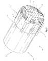
- FIG. 2illustrates an exemplary view of a core drill bit with an extended crown
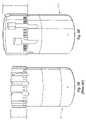
- FIG. 3Ashows an illustration of a side view of an exemplary conventional core drill bit
- FIG. 3Bshows an illustration of a side view of core drill bit with an extended cutting end height
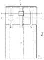
- FIG. 4shows an exemplary core drill bit with enclosed fluid/debris slots
- FIG. 5shows a side view of an exemplary drill bit with an extended cutting-end height that has been eroded down, as depicted by hatching;
- FIG. 6Ashows an illustration of a convention core drill bit used in an exemplary drilling process
- FIG. 6Bshows an illustration a core drill bit with an extended cutting end height used in an exemplary drilling process.
- the apparatus and associated methods of using the apparatuscan be implemented and used without employing these specific details. Indeed, the apparatus and associated methods can be placed into practice by modifying the illustrated apparatus and associated methods and can be used in conjunction with any apparatus and techniques conventionally used in the industry. For example, while the description below focuses on an extended crown height for diamond-impregnated core drill bits, the apparatus and associated methods can be equally applied in carbide, ceramic, or other super-abrasive core drill bits. Indeed, the apparatus and associated methods may be implemented in many other in ground drilling applications such as navi-drills, full hole drills, and the like.
- FIG. 2One example of such a core drill bit is illustrated in FIG. 2 .
- the drill bit 20contains a first section 21 that connects to the rest of the drill (i.e., a drill rod).
- the drill bit 20also contains a second section 23 that is used to cut the desired materials during the drilling process.
- the body of the drill bithas an outer surface 8 and an inner surface 4 that contains a hollow portion therein. With this configuration, pieces of the material being drilled can pass through the hollow portion and up through the drill string.
- the drill bit 20may be any size, and may therefore be used to collect core samples of any size. While the drill bit may have any diameter and may be used to remove and collect core samples with any desired diameter, the diameter of the drill bit generally ranges from about 1 to about 12 inches. As well, while the kerf of the drill bit (the radius of the outer surface minus the radius of the inner surface) may be any width, it generally ranges from about 1 ⁇ 2 to about 6 inches.
- the first section of the drill bit 20may be made of any suitable material.
- the first sectionmay be made of steel or a matrix casting with a hard particulate material in a binder.
- the hard particulate materialinclude those known in the art, as well as tungsten carbide, W, Fe, Co, Mo, and combinations thereof.
- a binder that can be usedinclude those known in the art, as well as copper alloys, Ag, Zn, Ni, Co, Mo, and combinations thereof
- the first section 21may contain a chuck end 22 as shown in FIG. 2 .
- This chuck end 22sometimes called a blank, bit body, or shank, may be used for any purpose, including connecting the drill bit to nearest the drill rod.
- the chuck end 22can be configured as known in the art to connect the drill bit 20 to any desired type of drill rod.
- the chuck end 22may include any known mounting structure for attaching the drill bit to any conventional drill rod, e.g., a threaded pin connection used to secure the drill bit to the drive shaft at the end of a drill string.
- the second section 23 of the core drill bit 20may comprise a cutting portion (or cutting end) 24 .
- the cutting portion 24may be constructed of any material(s) known in the art.
- a powder of tungsten carbide, boron nitride, iron, steel, Co, Mo, W, and/or a ferrous alloymay be placed in a mold. The powder may then be sintered and infiltrated with a molten binder, such as a copper, iron, Ag, Zn, or nickel alloy, to form the cutting portion.
- the second section 23 of the drill bitmay be made of one or more layers.
- FIG. 2illustrates that the cutting portion 24 may contain two layers: a matrix layer 16 that performs the cutting operation and a backing layer 18 , which connects the matrix layer to the second section of the drill bit.
- the matrix layer 16may contain a cutting media which abrades and erodes the material being drilled. Any cutting media may be used in the matrix layer 16 , including natural or synthetic diamonds (e.g., polycrystalline diamond compacts).
- the cutting mediamay be embedded or impregnated into the matrix layer 16 . And any size, grain, quality, shape, grit, concentration, etc. of cutting media may be used in the matrix layer 16 as known in the art.
- the cutting portion 24 of the drill bitmay be manufactured to any desired specification or given any desired characteristic(s). In this way, the cutting portion may be custom-engineered to possess optimal characteristics for drilling specific materials. For example, a hard, abrasion resistant matrix may be made to drill soft, abrasive, unconsolidated formations, while a soft ductile matrix may be made to drill an extremely hard, non-abrasive, consolidated formation. In this way, the bit matrix hardness may be matched to particular formations, allowing the matrix layer 16 to erode at a controlled, desired rate.
- the height (A) of the drill bit crown(as shown in FIG. 2 ) can be extended to be longer than those currently known in the art while maintaining its structural integrity. Conventional crown heights are often limited to sixteen to seventeen millimeters or less because of the need to maintain the structural stability. In some embodiments of the present drill bits, the crown height A can be increased to be several times these lengths. In some circumstances, the crown height can range from about 1 to about 6 inches. In other circumstances, the crown height can range from about 2 to about 5 inches. In yet other circumstances, the crown height can be about 3 inches.
- FIG. 3Billustrates one example of drill bit 20 with the extended crown height
- FIG. 3Aillustrates a conventional core drill bit 40
- the first section 21 of the drill bit 20is roughly the same size as a corresponding first section 42 of the conventional drill bit 40
- the corresponding crown height (A-) of the conventional drill bit 40is roughly half the height of the extended crown height A of the drill bit 20 .
- the cutting portion of the drill bitcan contain a plurality of fluid/debris ways 28 and 32 , as shown in FIG. 2 .
- These fluid/debris waysmay be located behind the proximal face 36 or along the length of the cutting portion 24 of the drill bit 20 .
- Those fluid/debris ways located at the proximal face 36will be referred to as notches, while those located behind the proximal face 36 will be referred to as slots 32 .
- the fluid/debris waysmay have different configurations to influence the hydraulics, fluid/debris flow, as well as the surface area used in the cutting action.
- the cutting portion 24may have any number of fluid/debris notches 28 that provides the desired amount of fluid/debris flow and also allows it to maintain the structural integrity needed.
- FIG. 2shows that the drill bit 20 may have three fluid/debris notches 28 .
- the drill bitmay have fewer notches, such as two or even one fluid/debris notch.
- the drillmay have more notches, such as 3 or even 40 notches.
- the fluid/debris notches 28may be evenly or unevenly spaced around the circumference of the drill bit.
- FIG. 2depicts a drill bit that has three fluid/debris notches that are evenly spaced. In other situations, though, the notches 28 need not be evenly spaced around the circumference.
- the fluid/debris notches 28may have any shape that allows them to operate as intended. Examples of the types of shapes that the notches 28 can have include rectangular (as illustrated in FIG. 2 ), square, triangular, circular, trapezoidal, polygonal, elliptical, or any combination thereof.
- the fluid/debris notches 28may have any width or length that allows them to operate as intended.
- the fluid/debris notches 28may have any size that will allow them to operate as intended.
- a drill bitcould have many small fluid/debris notches.
- a drill bitmay have a few large fluid/debris notches and some small notches.
- the drill bit 20contains just a few (3) large fluid/debris notches 28 .
- the fluid/debris notches 28may be configured the same or differently.
- the notches 28 depicted in FIG. 2are made with substantially the same configuration. But in other embodiments, the notches 28 can be configured with different sizes and shapes.
- the fluid/debris notches 28may also be placed in the cutting portion with any desired orientation.
- the notches 28may point to the center of the circumference of the drill bit. In other words, they may be perpendicular to the circumference of the drill bit.
- the fluid/debris notchesmay be orthogonal to the circumference of the drill bit.
- the notchesmay be offset proximally, distally, to the right, left, or any combination of these orientations.
- the cutting portion 24 of the drill bitalso contains one or more fluid/debris slot (or slots) 32 .
- These slots 32have an opening 10 on the outer surface 8 of the drill bit 20 and an opening 12 on the inner surface 4 of the drill bit 20 . Because they are enclosed in the body of the crown, the fluid/debris slots 32 may be located in any part of the cutting portion 24 except the proximal face 36 . As the cutting portion erodes away, the fluid/debris slots are progressively exposed as the erosion proceeds along the length of the crown. As this happens, the fluid/debris slots then become fluid/debris notches. In this manner, drill bits with such fluid/debris slots may have a continuous supply of fluid/debris ways until the extended crown is worn completely away. Such a configuration therefore allows a longer crown height while maintaining the structural integrity of the crown.
- the cutting portion 24may have any number of fluid/debris slots 32 that allows it to maintain the desired structural integrity.
- the drill bitmay have 0 to 20 slots. In other embodiments, though, the drill bit may contain anywhere from 1 to 3 slots. In the examples of the drill bit shown in FIG. 2 , the drill bit 20 contains 6 fluid/debris slots 32 .
- the fluid/debris slots 32may be evenly or unevenly spaced around the circumference of the drill bit.
- FIG. 2depicts a drill bit that has 6 slots that are evenly spaced. In other situations, though, the slots 32 need not be evenly spaced around the circumference.
- the fluid/debris slots 32may have any shape that allows them to operate as intended. Examples of the types of shapes that the slots can have include rectangular (as illustrated in FIG. 2 ), triangular, square, circular, trapezoidal, polygonal, elliptical, or any combination thereof.
- the fluid/debris slots 32may have any width or length that allows them to operate as intended.
- the fluid/debris slots 32may have of any size that will allow them to operate as intended.
- a drill bitcould have many small fluid/debris slots.
- a drill bitmay have a few large fluid/debris slots and some small slots.
- the drill bit 20contains just large fluid/debris slots 32 .
- the fluid/debris slots 32may be configured the same or differently.
- the slots 32 depicted in FIG. 2are made with substantially the same configuration. But in other embodiments, the slots can be configured with different sizes and shapes.
- the bitmay have multiple rows of thin, narrow fluid/debris slots.
- the described drill bitmay have a single row of tall, wide fluid/debris slots.
- the fluid/debris slots 32may also be placed in the cutting portion with any desired orientation.
- the slots 32may be oriented toward the center of the circumference of the drill bit and, therefore, may be perpendicular to the circumference of the drill bit.
- the fluid/debris slotsmay be orthogonal to the circumference of the drill bit.
- the slotsmay be offset proximally, distally, to the right, left, or any combination thereof.
- the drill bitsmay include one or multiple layer(s) (or rows) of fluid/debris slots, and each row may contain one or more fluid/debris slots.
- FIG. 4shows a drill bit that has six fluid/debris slots 32 .
- the drill bit 20has three fluid/debris slots in a first row 90 .
- the drill bit 20has a second row 92 of three more fluid/debris slots 32 .
- the drill bit 20could be configured to have 3 rows of two slots each, or even 6 rows of one slot each.
- the rowscan contain the same or different number of slots.
- the number of fluid/debris slots in each rowmay or may not be equal to the number of fluid/debris notches 28 in the proximal face 36 of the drill bit.
- the first opening 10 of the fluid/debris slotsmay be larger or smaller (or have a different shape or size) than the second opening 12 on the inner surface.
- the first openingcould be a small trapezoidal shape and the second opening could have a larger, rectangular opening.
- the first opening 10 and the second opening 12 of the fluid/debris slots 32may be offset longitudinally or laterally from each other.
- a portion of the fluid/debris slots 32may laterally overlap one or more fluid/debris notches. As well, a portion of a fluid/debris slot may laterally overlap another slot. Thus, before a fluid/debris slot (which has become a notch) erodes completely, the other fluid/debris slot is opened to become a notch, allowing the drill bit to continue to cut efficiently.
- the fluid/debris slotsmay be placed in the drill bit in any configuration that provides the desired fluid dynamics.
- the fluid/debris slotsmay be configured in a staggered manner throughout the cutting portion of the drill bit. They may also be staggered with the fluid/debris notches.
- the slots and/or notchesmay be arranged in rows and each row may have a row of fluid/debris slots that are offset to one side of the fluid/debris slots and/or notches in the row just proximal to it. Additionally, even though the slots/notches may not be touching, they may overlap laterally as described above.
- the fluid/debris notches 28 and/or slots 32may be configured in a stepped manner.
- each notch in the proximal facemay have a slot located distally and to one side of it (i.e., to the right or left). Slots in the next row may then have another slot located distally to them and off to the same side as the slot/notch relationship in the first row.
- the fluid/debris notches and or slotsmay be configured in both a staggered and stepped manner as shown in FIG. 2 .
- three fluid/debris notches 28are located in the proximal face of the cutting portion 24 of the drill bit 20 .
- a corresponding fluid/debris slotis located and slightly laterally overlaps the notch.
- a second set of fluid/debris slots 32is located.
- the cutting portion 24may optionally contain flutes 40 . These flutes may serve many purposes, including aiding in cooling the bit, removing debris, improving the bit hydraulics and making the fluid/debris notches and/or slots more efficient.
- the flutesmay be placed in the drill bit in any configuration. In some embodiments, the flutes may be located on the outer surface and are therefore called outer flutes. In another embodiment, the flutes may be located on the inner surface and are therefore called inner flutes. In yet another embodiment, the flutes may be located in between the inner and the outer surface and are therefore face flutes. In still other embodiments, the flutes may be located in the drill bit in any combination of these flute locations.
- the size, shape, angle, number, and location of the flutesmay be selected to obtain the desired results for which the flute(s) is used.
- the flutesmay have any positional relationship relative to the fluid/debris notches and/or slots, including that relationship shown in FIG. 2 .
- an increase in the penetration ratewas observed. This increased penetration rate was likely due to the increased bit face flushing, which may be due to the combination of larger waterways and the inner and outer diameter flutes.
- the cutting portion 24 of the drill bitmay have any desired crown profile.
- the cutting portion of the drill bitmay have a V-ring bit crown profile, a flat face bit crown profile, a stepped bit crown profile, or a semi-round bit crown profile.
- the drill bithas the crown profile illustrated in FIG. 2 .
- any additional feature known in the artmay optionally be implemented with the drill bit 20 .
- the drill bitmay have additional gauge protection, hard-strip deposits, various bit profiles, and combinations thereof.
- Protector gaugesmay be included to reduce the damage to the well's casing and to the drill bit as it is lowered into the casing.
- the first section of the drill bitmay have hard-metal strips applied that may prevent the premature erosion.
- the drill bitmay also optionally contain natural diamonds, polycrystalline diamonds, thermally stable diamonds, tungsten carbide, pins, cubes, or other gauge protection on the inner or outer surface of the core drill bit.
- the drill bits described abovecan be made using any method that provides them with the features described above.
- the first sectioncan be made in any manner known in the art.
- the first sectioni.e., the steel blank
- the second sectioncan also be made in any manner known in the art, including infiltration, sintering, machining, casting, or the like.
- the notches 28 and slots 32can be made in the second section either during or after such processes by machining, water jets, laser, Electrical Discharge Machining (EDM), and infiltration.
- EDMElectrical Discharge Machining
- the first section 21can then be connected to the second section 23 of the drill bit using any method known in the art.
- the first sectionmay be present in the mold that is used to form the second section of the drill bit and the two ends of the body may be fused together.
- the first and second sectionscan be mated in a separate process, such as by brazing, welding, or adhesive bonding.
- the drill bitsmay be used in any drilling operation known in the art. As with other core drill bits, they may be attached to the end of a drill string, which is in turn connected to a drilling rig. As the core drill bit turns, it grinds away the materials in the subterranean formations that are being drilled. The matrix layer 16 and the fluid/debris notches 28 erode over time. As the fluid matrix layer 16 erodes, the fluid/debris slots 32 may be exposed and become fluid/debris notches. As more of the matrix layer erodes, additional fluid/debris slots are then exposed to become fluid/debris notches. This process continues until the cutting portion of a drill bit has been consumed and the drilling string need be tripped and the bit replaced.
- FIG. 5shows one example of a worn drill bit 80 .
- the entire row of fluid/debris notches 128 in the cutting portion 124 of the drill bit 80has been eroded, as shown by the hatching. Additionally, a first row 106 of fluid/debris slots 132 has eroded. Thus, a second row 108 of fluid/debris slots 132 remains. Despite this erosion, the drill bit in this condition may still be used just as long as a conventional drill bit.
- the height of the crownis increased beyond those lengths conventionally used without sacrificing structural integrity.
- the usable life of the drill bitcan be magnified by about 1.5 to about 2.5 times the normal usable life.
- the drilling processbecomes more efficient since less tripping in and out if the drill string is needed.
- the penetration rate of the drill bitscan be increase by up to about 25%.
- the drill bithas consistent cutting parameters since the bit surface consistently replaces itself with a consistent cutting surface area.
- the following non-limiting Exampleillustrates the drill bits and associated methods of using the drill bits.
- a first, conventional drill bitwas obtained off-the-shelf.
- the first drill bitwas manufactured to have an Alpha 7COM (Boart Longyear Co.) formulation and measured to have a crown height of 12.7 mm.
- the first drill bithad a bit size of 2.965′′ OD ⁇ 1.875′′ ID (NQ).
- the first drill bitis depicted as Drill # 1 in FIG. 6A .
- a second drill bitwas manufactured to contain the slots described above.
- the second drill bitwas also made with an Alpha 7COM (Boart Longyear Co.) formulation, but contained six rectangular slots with a size of 0.520′′ wide by 0.470′′ high.
- the second drill bitwas also manufactured with nine 0.125′′ diameter inner diameter flutes and nine 0.187′′ outer diameter flutes.
- the second drill bitwas also manufactured with a crown height of 25.4 mm and a bit size of 2.965′′ OD ⁇ 1.875′′ ID (NQ).
- the second drill bitis depicted as Drill # 2 in FIG. 6B .
- Both drill bitswere then used to drill through a medium hard granite formation using a standard drill rig.
- the first drill bitwas able to drill through 200 meters, at penetration rate of about 6-8 inches per minute, before the crown was worn out and needed to be replaced.
- the second drill bitwas then used on the same drill rig to drill through similar material further down in the same drill hole.
- the second drill bitwas able to drill through about 488 meters, at penetration rate of about 8-10 inches per minute, before the crown wore out and needed to be replaced.
- the second drill bitwas therefore able to increase the penetration rate by up to about 25%. As well, the usable life of the second drill bit was extended to be about 2.5 times longer that the comparable, conventional drill bit.
Landscapes
- Engineering & Computer Science (AREA)
- Geology (AREA)
- Life Sciences & Earth Sciences (AREA)
- Mining & Mineral Resources (AREA)
- Physics & Mathematics (AREA)
- Environmental & Geological Engineering (AREA)
- Fluid Mechanics (AREA)
- Mechanical Engineering (AREA)
- General Life Sciences & Earth Sciences (AREA)
- Geochemistry & Mineralogy (AREA)
- Processing Of Stones Or Stones Resemblance Materials (AREA)
- Earth Drilling (AREA)
- Drilling Tools (AREA)
Abstract
Description
Claims (9)
Priority Applications (32)
| Application Number | Priority Date | Filing Date | Title |
|---|---|---|---|
| US11/610,680US7628228B2 (en) | 2006-12-14 | 2006-12-14 | Core drill bit with extended crown height |
| ES17199369TES2866889T3 (en) | 2006-12-14 | 2007-12-14 | Core drilling bit |
| EP17199369.4AEP3299573B1 (en) | 2006-12-14 | 2007-12-14 | Core drill bit |
| ZA200903801AZA200903801B (en) | 2006-12-14 | 2007-12-14 | Core drill bit with extended matrix height |
| AU2007333850AAU2007333850B2 (en) | 2006-12-14 | 2007-12-14 | Core drill bit with extended matrix height |
| CN2007800510708ACN101652532B (en) | 2006-12-14 | 2007-12-14 | Core drill bit with extended matrix height |
| ES07869300.9TES2659515T3 (en) | 2006-12-14 | 2007-12-14 | Drill drill bit with extended die height |
| EP07869300.9AEP2122111B1 (en) | 2006-12-14 | 2007-12-14 | Core drill bit with extended matrix height |
| PCT/US2007/087619WO2008076908A2 (en) | 2006-12-14 | 2007-12-14 | Core drill bit with extended matrix height |
| CA2826590ACA2826590C (en) | 2006-12-14 | 2007-12-14 | Core drill bit with extended matrix height |
| CA2671061ACA2671061C (en) | 2006-12-14 | 2007-12-14 | Core drill bit with extended matrix height |
| US12/564,540US7828090B2 (en) | 2006-12-14 | 2009-09-22 | Drill bits with enclosed fluid slots and internal flutes |
| US12/564,779US7918288B2 (en) | 2006-12-14 | 2009-09-22 | Drill bits with enclosed fluid slots and method |
| US12/567,477US7958954B2 (en) | 2006-12-14 | 2009-09-25 | Drill bits with enclosed slots |
| US12/568,231US7874384B2 (en) | 2006-12-14 | 2009-09-28 | Drill bits with increased crown height |
| US12/568,204US7909119B2 (en) | 2006-12-14 | 2009-09-28 | Drill bits with notches and enclosed slots |
| US12/638,229US8459381B2 (en) | 2006-12-14 | 2009-12-15 | Drill bits with axially-tapered waterways |
| US29/354,586USD647114S1 (en) | 2006-12-14 | 2010-01-26 | Drill bit with tapered waterway |
| US29/354,592USD647115S1 (en) | 2006-12-14 | 2010-01-26 | Drill bit waterway |
| US29/354,579USD622745S1 (en) | 2006-12-14 | 2010-01-26 | Drill bit with tapered waterway |
| AU201013488FAU332261S (en) | 2006-12-14 | 2010-05-24 | Drill bit with tapered waterway |
| AU201013487FAU332260S (en) | 2006-12-14 | 2010-05-24 | Drill bit with tapered waterway |
| AU201012082FAU332257S (en) | 2006-12-14 | 2010-05-24 | Drill bit with tapered waterway |
| CL2010000617FCL2010000617S1 (en) | 2006-12-14 | 2010-06-11 | End of hollow cylindrical auger, in whose upper end it has three transverse channels of irregular trapezoidal section and decreasing height; and a series of vertical semi-cylindrical notches in a projection located on its upper perimeter. |
| US12/909,187US8051929B2 (en) | 2006-12-14 | 2010-10-21 | Core drill bits with enclosed fluid slots |
| AU2011201710AAU2011201710B2 (en) | 2006-12-14 | 2011-04-15 | Core drill bit with extended matrix height |
| AU2011201709AAU2011201709B2 (en) | 2006-12-14 | 2011-04-15 | Core drill bit with extended matrix height |
| AU2011201713AAU2011201713C1 (en) | 2006-12-14 | 2011-04-15 | Core drill bit with extended matrix height |
| AU2011201706AAU2011201706B2 (en) | 2006-12-14 | 2011-04-15 | Core drill bit with extended matrix height |
| AU2011201707AAU2011201707B2 (en) | 2006-12-14 | 2011-04-15 | Core drill bit with extended matrix height |
| US13/914,233US9074429B2 (en) | 2006-12-14 | 2013-06-10 | Drill bits with axially-tapered waterways |
| US14/246,888US9500036B2 (en) | 2006-12-14 | 2014-04-07 | Single-waterway drill bits and systems for using same |
Applications Claiming Priority (1)
| Application Number | Priority Date | Filing Date | Title |
|---|---|---|---|
| US11/610,680US7628228B2 (en) | 2006-12-14 | 2006-12-14 | Core drill bit with extended crown height |
Related Parent Applications (5)
| Application Number | Title | Priority Date | Filing Date |
|---|---|---|---|
| US12/564,540Continuation-In-PartUS7828090B2 (en) | 2006-12-14 | 2009-09-22 | Drill bits with enclosed fluid slots and internal flutes |
| US12/567,477Continuation-In-PartUS7958954B2 (en) | 2006-12-14 | 2009-09-25 | Drill bits with enclosed slots |
| US12/568,231Continuation-In-PartUS7874384B2 (en) | 2006-12-14 | 2009-09-28 | Drill bits with increased crown height |
| US12/568,204Continuation-In-PartUS7909119B2 (en) | 2006-12-14 | 2009-09-28 | Drill bits with notches and enclosed slots |
| US14/085,218Continuation-In-PartUS9506298B2 (en) | 2006-12-14 | 2013-11-20 | Drill bits having blind-hole flushing and systems for using same |
Related Child Applications (5)
| Application Number | Title | Priority Date | Filing Date |
|---|---|---|---|
| US12/564,540ContinuationUS7828090B2 (en) | 2006-12-14 | 2009-09-22 | Drill bits with enclosed fluid slots and internal flutes |
| US12/564,779ContinuationUS7918288B2 (en) | 2006-12-14 | 2009-09-22 | Drill bits with enclosed fluid slots and method |
| US12/567,477DivisionUS7958954B2 (en) | 2006-12-14 | 2009-09-25 | Drill bits with enclosed slots |
| US12/568,231DivisionUS7874384B2 (en) | 2006-12-14 | 2009-09-28 | Drill bits with increased crown height |
| US12/568,204DivisionUS7909119B2 (en) | 2006-12-14 | 2009-09-28 | Drill bits with notches and enclosed slots |
Publications (2)
| Publication Number | Publication Date |
|---|---|
| US20080142262A1 US20080142262A1 (en) | 2008-06-19 |
| US7628228B2true US7628228B2 (en) | 2009-12-08 |
Family
ID=39525775
Family Applications (7)
| Application Number | Title | Priority Date | Filing Date |
|---|---|---|---|
| US11/610,680Active2027-02-20US7628228B2 (en) | 2006-12-14 | 2006-12-14 | Core drill bit with extended crown height |
| US12/564,779Expired - Fee RelatedUS7918288B2 (en) | 2006-12-14 | 2009-09-22 | Drill bits with enclosed fluid slots and method |
| US12/564,540ActiveUS7828090B2 (en) | 2006-12-14 | 2009-09-22 | Drill bits with enclosed fluid slots and internal flutes |
| US12/567,477Expired - Fee RelatedUS7958954B2 (en) | 2006-12-14 | 2009-09-25 | Drill bits with enclosed slots |
| US12/568,204Expired - Fee RelatedUS7909119B2 (en) | 2006-12-14 | 2009-09-28 | Drill bits with notches and enclosed slots |
| US12/568,231ActiveUS7874384B2 (en) | 2006-12-14 | 2009-09-28 | Drill bits with increased crown height |
| US12/909,187ActiveUS8051929B2 (en) | 2006-12-14 | 2010-10-21 | Core drill bits with enclosed fluid slots |
Family Applications After (6)
| Application Number | Title | Priority Date | Filing Date |
|---|---|---|---|
| US12/564,779Expired - Fee RelatedUS7918288B2 (en) | 2006-12-14 | 2009-09-22 | Drill bits with enclosed fluid slots and method |
| US12/564,540ActiveUS7828090B2 (en) | 2006-12-14 | 2009-09-22 | Drill bits with enclosed fluid slots and internal flutes |
| US12/567,477Expired - Fee RelatedUS7958954B2 (en) | 2006-12-14 | 2009-09-25 | Drill bits with enclosed slots |
| US12/568,204Expired - Fee RelatedUS7909119B2 (en) | 2006-12-14 | 2009-09-28 | Drill bits with notches and enclosed slots |
| US12/568,231ActiveUS7874384B2 (en) | 2006-12-14 | 2009-09-28 | Drill bits with increased crown height |
| US12/909,187ActiveUS8051929B2 (en) | 2006-12-14 | 2010-10-21 | Core drill bits with enclosed fluid slots |
Country Status (8)
| Country | Link |
|---|---|
| US (7) | US7628228B2 (en) |
| EP (2) | EP3299573B1 (en) |
| CN (1) | CN101652532B (en) |
| AU (6) | AU2007333850B2 (en) |
| CA (2) | CA2671061C (en) |
| ES (2) | ES2866889T3 (en) |
| WO (1) | WO2008076908A2 (en) |
| ZA (1) | ZA200903801B (en) |
Cited By (17)
| Publication number | Priority date | Publication date | Assignee | Title |
|---|---|---|---|---|
| US20100006344A1 (en)* | 2006-12-14 | 2010-01-14 | Longyear Tm, Inc. | Drill bits with enclosed fluid slots and internal flutes |
| US20100089660A1 (en)* | 2006-12-14 | 2010-04-15 | Longyear Tm, Inc. | Drill bits with axially-tapered waterways |
| USD622745S1 (en) | 2006-12-14 | 2010-08-31 | Longyear Tm, Inc. | Drill bit with tapered waterway |
| US20110067924A1 (en)* | 2009-09-22 | 2011-03-24 | Longyear Tm, Inc. | Impregnated cutting elements with large abrasive cutting media and methods of making and using the same |
| US20120111635A1 (en)* | 2010-04-13 | 2012-05-10 | George Caffell | Sample Encapsulation and Cache Device and Methods |
| WO2013028256A2 (en) | 2011-08-24 | 2013-02-28 | Longyear Tm, Inc. | Impregnated drilling tools including elongated structures |
| WO2013062536A1 (en) | 2011-10-25 | 2013-05-02 | Longyear Tm, Inc. | High-strength, high-hardness binders and drilling tools formed using the same |
| US8657894B2 (en) | 2011-04-15 | 2014-02-25 | Longyear Tm, Inc. | Use of resonant mixing to produce impregnated bits |
| US20150016909A1 (en)* | 2011-12-22 | 2015-01-15 | Hilti Aktiengesellschaft | Drill bit with an exchangeable cutting portion |
| US8991524B2 (en) | 2010-09-13 | 2015-03-31 | Longyear Tm, Inc. | Impregnated drill bits with integrated reamers |
| US20150136494A1 (en)* | 2013-11-20 | 2015-05-21 | Longyear Tm, Inc. | Drill Bits Having Flushing And Systems For Using Same |
| USD752662S1 (en)* | 2013-08-09 | 2016-03-29 | Hilti Aktiengesellschaft | Change module |
| US9421671B2 (en) | 2011-02-09 | 2016-08-23 | Longyear Tm, Inc. | Infiltrated diamond wear resistant bodies and tools |
| US9500036B2 (en) | 2006-12-14 | 2016-11-22 | Longyear Tm, Inc. | Single-waterway drill bits and systems for using same |
| US9506298B2 (en) | 2013-11-20 | 2016-11-29 | Longyear Tm, Inc. | Drill bits having blind-hole flushing and systems for using same |
| US20170001249A1 (en)* | 2013-12-20 | 2017-01-05 | Hilti Aktiengesellschaft | Drill bit with a replaceable cutting portion |
| US10702975B2 (en) | 2015-01-12 | 2020-07-07 | Longyear Tm, Inc. | Drilling tools having matrices with carbide-forming alloys, and methods of making and using same |
Families Citing this family (73)
| Publication number | Priority date | Publication date | Assignee | Title |
|---|---|---|---|---|
| US9101978B2 (en) | 2002-12-08 | 2015-08-11 | Baker Hughes Incorporated | Nanomatrix powder metal compact |
| US9109429B2 (en) | 2002-12-08 | 2015-08-18 | Baker Hughes Incorporated | Engineered powder compact composite material |
| US9079246B2 (en) | 2009-12-08 | 2015-07-14 | Baker Hughes Incorporated | Method of making a nanomatrix powder metal compact |
| US9682425B2 (en) | 2009-12-08 | 2017-06-20 | Baker Hughes Incorporated | Coated metallic powder and method of making the same |
| US20080181735A1 (en)* | 2007-01-25 | 2008-07-31 | Ting Fong Electric & Machinery Co., Ltd. | Method for manufacturing drill cutters and structure thereof |
| MX2010002236A (en)* | 2007-09-05 | 2010-03-25 | Groupe Fordia Inc | Drill bit. |
| AU2008205690B2 (en)* | 2008-08-15 | 2011-06-02 | Sandvik Intellectual Property Ab | Core drill bit |
| CA2735288A1 (en)* | 2008-08-25 | 2010-03-04 | Ira Kozak | Tool for working on repaired underground pipes |
| WO2011017625A2 (en)* | 2009-08-07 | 2011-02-10 | Smith International, Inc. | Method of forming a thermally stable diamond cutting element |
| US8579053B2 (en)* | 2009-08-07 | 2013-11-12 | Smith International, Inc. | Polycrystalline diamond material with high toughness and high wear resistance |
| CA2770306A1 (en)* | 2009-08-07 | 2011-02-10 | Smith International, Inc. | Functionally graded polycrystalline diamond insert |
| WO2011017592A2 (en)* | 2009-08-07 | 2011-02-10 | Smith International, Inc. | Diamond transition layer construction with improved thickness ratio |
| CN105422014B (en) | 2009-08-07 | 2018-03-13 | 史密斯国际有限公司 | Cutting element |
| WO2011017673A2 (en)* | 2009-08-07 | 2011-02-10 | Smith International, Inc. | Thermally stable polycrystalline diamond constructions |
| US10240419B2 (en) | 2009-12-08 | 2019-03-26 | Baker Hughes, A Ge Company, Llc | Downhole flow inhibition tool and method of unplugging a seat |
| US9127515B2 (en) | 2010-10-27 | 2015-09-08 | Baker Hughes Incorporated | Nanomatrix carbon composite |
| US9243475B2 (en) | 2009-12-08 | 2016-01-26 | Baker Hughes Incorporated | Extruded powder metal compact |
| US8528633B2 (en) | 2009-12-08 | 2013-09-10 | Baker Hughes Incorporated | Dissolvable tool and method |
| US9227243B2 (en) | 2009-12-08 | 2016-01-05 | Baker Hughes Incorporated | Method of making a powder metal compact |
| US9090955B2 (en) | 2010-10-27 | 2015-07-28 | Baker Hughes Incorporated | Nanomatrix powder metal composite |
| US9115551B2 (en)* | 2011-02-21 | 2015-08-25 | Ehwa Diamond Industrial Co., Ltd. | Reaming shell for mining |
| US8631876B2 (en) | 2011-04-28 | 2014-01-21 | Baker Hughes Incorporated | Method of making and using a functionally gradient composite tool |
| US9080098B2 (en) | 2011-04-28 | 2015-07-14 | Baker Hughes Incorporated | Functionally gradient composite article |
| US9139928B2 (en) | 2011-06-17 | 2015-09-22 | Baker Hughes Incorporated | Corrodible downhole article and method of removing the article from downhole environment |
| US20130014998A1 (en)* | 2011-07-11 | 2013-01-17 | Baker Hughes Incorporated | Downhole cutting tool and method |
| US9707739B2 (en) | 2011-07-22 | 2017-07-18 | Baker Hughes Incorporated | Intermetallic metallic composite, method of manufacture thereof and articles comprising the same |
| US8783365B2 (en) | 2011-07-28 | 2014-07-22 | Baker Hughes Incorporated | Selective hydraulic fracturing tool and method thereof |
| US9643250B2 (en) | 2011-07-29 | 2017-05-09 | Baker Hughes Incorporated | Method of controlling the corrosion rate of alloy particles, alloy particle with controlled corrosion rate, and articles comprising the particle |
| US9833838B2 (en) | 2011-07-29 | 2017-12-05 | Baker Hughes, A Ge Company, Llc | Method of controlling the corrosion rate of alloy particles, alloy particle with controlled corrosion rate, and articles comprising the particle |
| US9057242B2 (en) | 2011-08-05 | 2015-06-16 | Baker Hughes Incorporated | Method of controlling corrosion rate in downhole article, and downhole article having controlled corrosion rate |
| US9033055B2 (en) | 2011-08-17 | 2015-05-19 | Baker Hughes Incorporated | Selectively degradable passage restriction and method |
| US9856547B2 (en) | 2011-08-30 | 2018-01-02 | Bakers Hughes, A Ge Company, Llc | Nanostructured powder metal compact |
| US9090956B2 (en) | 2011-08-30 | 2015-07-28 | Baker Hughes Incorporated | Aluminum alloy powder metal compact |
| US9109269B2 (en) | 2011-08-30 | 2015-08-18 | Baker Hughes Incorporated | Magnesium alloy powder metal compact |
| US9643144B2 (en) | 2011-09-02 | 2017-05-09 | Baker Hughes Incorporated | Method to generate and disperse nanostructures in a composite material |
| US9187990B2 (en) | 2011-09-03 | 2015-11-17 | Baker Hughes Incorporated | Method of using a degradable shaped charge and perforating gun system |
| US9133695B2 (en) | 2011-09-03 | 2015-09-15 | Baker Hughes Incorporated | Degradable shaped charge and perforating gun system |
| US9347119B2 (en) | 2011-09-03 | 2016-05-24 | Baker Hughes Incorporated | Degradable high shock impedance material |
| RU2473773C1 (en)* | 2011-09-26 | 2013-01-27 | Николай Митрофанович Панин | Diamond crown bit |
| US9482056B2 (en) | 2011-12-30 | 2016-11-01 | Smith International, Inc. | Solid PCD cutter |
| CN102536123B (en)* | 2012-01-16 | 2014-08-13 | 三原石油钻头厂 | Gas lift reverse circulation diamond bit |
| US9010416B2 (en) | 2012-01-25 | 2015-04-21 | Baker Hughes Incorporated | Tubular anchoring system and a seat for use in the same |
| US9068428B2 (en) | 2012-02-13 | 2015-06-30 | Baker Hughes Incorporated | Selectively corrodible downhole article and method of use |
| US9605508B2 (en) | 2012-05-08 | 2017-03-28 | Baker Hughes Incorporated | Disintegrable and conformable metallic seal, and method of making the same |
| US9816339B2 (en) | 2013-09-03 | 2017-11-14 | Baker Hughes, A Ge Company, Llc | Plug reception assembly and method of reducing restriction in a borehole |
| BR112016015209A2 (en)* | 2013-12-30 | 2017-08-08 | Longyear Tm Inc | DRILL AND DRILLING SYSTEM |
| US11167343B2 (en) | 2014-02-21 | 2021-11-09 | Terves, Llc | Galvanically-active in situ formed particles for controlled rate dissolving tools |
| TWI510335B (en)* | 2014-02-21 | 2015-12-01 | wei lin Tu | Water Feeding Connecter for Drill |
| US10689740B2 (en) | 2014-04-18 | 2020-06-23 | Terves, LLCq | Galvanically-active in situ formed particles for controlled rate dissolving tools |
| CA2936851A1 (en) | 2014-02-21 | 2015-08-27 | Terves, Inc. | Fluid activated disintegrating metal system |
| PE20161426A1 (en)* | 2014-04-07 | 2017-01-06 | Longyear Tm Inc | SINGLE WATER TRAIL DRILL BITS AND SYSTEMS TO USE THEM |
| US10751161B2 (en) | 2014-10-23 | 2020-08-25 | Medos International Sárl | Biceps tenodesis anchor implants |
| US10076374B2 (en) | 2014-10-23 | 2018-09-18 | Medos International Sárl | Biceps tenodesis delivery tools |
| US10034742B2 (en) | 2014-10-23 | 2018-07-31 | Medos International Sarl | Biceps tenodesis implants and delivery tools |
| US10856966B2 (en) | 2014-10-23 | 2020-12-08 | Medos International Sarl | Biceps tenodesis implants and delivery tools |
| US10729419B2 (en) | 2014-10-23 | 2020-08-04 | Medos International Sarl | Biceps tenodesis implants and delivery tools |
| US9910026B2 (en) | 2015-01-21 | 2018-03-06 | Baker Hughes, A Ge Company, Llc | High temperature tracers for downhole detection of produced water |
| PE20171508A1 (en) | 2015-03-05 | 2017-10-20 | Longyear Tm Inc | DISCHARGE DRILL HOLES |
| US10378303B2 (en) | 2015-03-05 | 2019-08-13 | Baker Hughes, A Ge Company, Llc | Downhole tool and method of forming the same |
| US9693856B2 (en) | 2015-04-22 | 2017-07-04 | DePuy Synthes Products, LLC | Biceps repair device |
| US10221637B2 (en) | 2015-08-11 | 2019-03-05 | Baker Hughes, A Ge Company, Llc | Methods of manufacturing dissolvable tools via liquid-solid state molding |
| US10016810B2 (en) | 2015-12-14 | 2018-07-10 | Baker Hughes, A Ge Company, Llc | Methods of manufacturing degradable tools using a galvanic carrier and tools manufactured thereof |
| US10231823B2 (en) | 2016-04-08 | 2019-03-19 | Medos International Sarl | Tenodesis implants and tools |
| US10231824B2 (en) | 2016-04-08 | 2019-03-19 | Medos International Sárl | Tenodesis anchoring systems and tools |
| US10413658B2 (en)* | 2017-03-31 | 2019-09-17 | Capillary Biomedical, Inc. | Helical insertion infusion device |
| CN107130933A (en)* | 2017-04-17 | 2017-09-05 | 武汉地大长江钻头有限公司 | Coring bit |
| CA3012511A1 (en) | 2017-07-27 | 2019-01-27 | Terves Inc. | Degradable metal matrix composite |
| CN108247859B (en)* | 2018-01-10 | 2023-08-25 | 江苏韦尔博新材料科技有限公司 | Brazing diamond fine hole drill for drilling hard and brittle materials |
| CN109736712A (en)* | 2019-01-08 | 2019-05-10 | 江苏友美工具有限公司 | Laser welding diamond core bit |
| CN109736713A (en)* | 2019-01-08 | 2019-05-10 | 江苏友美工具有限公司 | A kind of diamond core bit and its laser welding preparation process |
| CN111173457B (en)* | 2020-02-10 | 2024-07-05 | 北京探矿工程研究所 | Multilayer diamond core drill bit and manufacturing method thereof |
| EP4341525A4 (en)* | 2021-05-21 | 2025-01-15 | Veracio Ltd. | Continuous sampling drill bit |
| CN113622827B (en)* | 2021-08-31 | 2022-05-17 | 中国地质大学(武汉) | A diamond drill bit for drilling into fractured hard rock layers |
Citations (17)
| Publication number | Priority date | Publication date | Assignee | Title |
|---|---|---|---|---|
| US2966949A (en) | 1958-07-16 | 1961-01-03 | Jersey Prod Res Co | Full hole permanent drill bit |
| USRE26669E (en)* | 1968-05-09 | 1969-09-30 | Drilling bit | |
| US4128136A (en) | 1977-12-09 | 1978-12-05 | Lamage Limited | Drill bit |
| US4208154A (en) | 1978-03-21 | 1980-06-17 | Gundy William P | Core drill |
| US4499959A (en) | 1983-03-14 | 1985-02-19 | Christensen, Inc. | Tooth configuration for an earth boring bit |
| US5025871A (en) | 1989-04-05 | 1991-06-25 | Aulette Stewart | Drilling method and rotary drill bit crown |
| US5069584A (en)* | 1989-01-20 | 1991-12-03 | Hilti Aktiengesellschaft | Hollow drilling tool |
| US5316416A (en) | 1992-09-29 | 1994-05-31 | Ehwa Diamond Ind. Co., Ltd. | Diamond cutting tool for hard articles |
| US5628376A (en)* | 1994-10-15 | 1997-05-13 | Hilti Aktiengesellschaft | Drilling tool bit with a carrier member and cutter members |
| US5823276A (en)* | 1996-12-24 | 1998-10-20 | Beck, Iii; August H. | Diamond-tipped core barrel and method of using same |
| US5836409A (en) | 1994-09-07 | 1998-11-17 | Vail, Iii; William Banning | Monolithic self sharpening rotary drill bit having tungsten carbide rods cast in steel alloys |
| US5932508A (en) | 1996-09-04 | 1999-08-03 | Armstrong; Caoimhin Padraig | Manufacture of a metal bonded abrasive product |
| WO2001092677A1 (en)* | 2000-05-31 | 2001-12-06 | Boart Longyear Pty Ltd | Improved core sampling drill bit |
| US6595844B1 (en)* | 1998-09-10 | 2003-07-22 | Atock Co., Ltd. | Outer-diameter blade, inner-diameter blade, core drill and processing machines using same ones |
| US20050016775A1 (en)* | 2002-01-08 | 2005-01-27 | Toshio Hiranuma | Core drill |
| WO2006004494A1 (en) | 2004-07-01 | 2006-01-12 | Atlas Copco Craelius Ab | A drill bit |
| WO2006076795A1 (en) | 2005-01-18 | 2006-07-27 | Groupe Fordia Inc | Bit for drilling a hole |
Family Cites Families (20)
| Publication number | Priority date | Publication date | Assignee | Title |
|---|---|---|---|---|
| US367956A (en)* | 1887-08-09 | Hoeatio j | ||
| US994866A (en)* | 1909-10-04 | 1911-06-13 | Eugene Schmitz | Drilling apparatus. |
| US1163867A (en)* | 1915-02-15 | 1915-12-14 | Elmer E Shaffer | Shoe for drilling oil-wells. |
| US1572386A (en)* | 1923-07-16 | 1926-02-09 | Leroy G Gates | Rotary drill bit |
| US2147849A (en)* | 1937-08-23 | 1939-02-21 | Leo William Dominic | Tobacco container |
| US2147843A (en)* | 1938-03-18 | 1939-02-21 | R S Patrick Duluth | Method of casting diamond core drill bits |
| US2342931A (en)* | 1942-07-13 | 1944-02-29 | Reed Roller Bit Co | Drag bit |
| US2495400A (en)* | 1946-06-03 | 1950-01-24 | Jr Edward B Williams | Core bit |
| US2969122A (en)* | 1955-03-31 | 1961-01-24 | Norman Ind Inc Van | Hollow drill |
| US3215215A (en)* | 1962-08-27 | 1965-11-02 | Exxon Production Research Co | Diamond bit |
| US3495359A (en)* | 1968-10-10 | 1970-02-17 | Norton Co | Core drill |
| JPS5382601A (en)* | 1976-12-28 | 1978-07-21 | Tokiwa Kogyo Kk | Rotary grinding type excavation drill head |
| US4822757A (en)* | 1987-11-10 | 1989-04-18 | Mitsubishi Denki Kabushiki Kaisha | Semiconductor device and method of manufacturing the same |
| JP2998278B2 (en)* | 1991-05-14 | 2000-01-11 | 富士ゼロックス株式会社 | Mono-color editing method and apparatus in color image recording apparatus |
| USD342270S (en)* | 1992-09-29 | 1993-12-14 | Ehwa Diamond Ind. Co., Ltd. | Core drill for perforating stone |
| CN2479181Y (en)* | 2001-04-29 | 2002-02-27 | 石油地球物理勘探局装备制造总厂机械厂 | Three-most-cylinder drill bit for petroleum geological exploration |
| GB2415208B (en)* | 2004-06-18 | 2008-12-24 | Statoil Asa | Drag bit |
| US7189036B1 (en)* | 2005-04-29 | 2007-03-13 | Forest City Tool, Inc. | Coring bit |
| US7628228B2 (en)* | 2006-12-14 | 2009-12-08 | Longyear Tm, Inc. | Core drill bit with extended crown height |
| US7984773B2 (en)* | 2008-05-13 | 2011-07-26 | Longyear Tm, Inc. | Sonic drill bit for core sampling |
- 2006
- 2006-12-14USUS11/610,680patent/US7628228B2/enactiveActive
- 2007
- 2007-12-14CACA2671061Apatent/CA2671061C/enactiveActive
- 2007-12-14CACA2826590Apatent/CA2826590C/enactiveActive
- 2007-12-14EPEP17199369.4Apatent/EP3299573B1/enactiveActive
- 2007-12-14WOPCT/US2007/087619patent/WO2008076908A2/enactiveApplication Filing
- 2007-12-14EPEP07869300.9Apatent/EP2122111B1/enactiveActive
- 2007-12-14ZAZA200903801Apatent/ZA200903801B/enunknown
- 2007-12-14ESES17199369Tpatent/ES2866889T3/enactiveActive
- 2007-12-14CNCN2007800510708Apatent/CN101652532B/ennot_activeExpired - Fee Related
- 2007-12-14AUAU2007333850Apatent/AU2007333850B2/enactiveActive
- 2007-12-14ESES07869300.9Tpatent/ES2659515T3/enactiveActive
- 2009
- 2009-09-22USUS12/564,779patent/US7918288B2/ennot_activeExpired - Fee Related
- 2009-09-22USUS12/564,540patent/US7828090B2/enactiveActive
- 2009-09-25USUS12/567,477patent/US7958954B2/ennot_activeExpired - Fee Related
- 2009-09-28USUS12/568,204patent/US7909119B2/ennot_activeExpired - Fee Related
- 2009-09-28USUS12/568,231patent/US7874384B2/enactiveActive
- 2010
- 2010-10-21USUS12/909,187patent/US8051929B2/enactiveActive
- 2011
- 2011-04-15AUAU2011201709Apatent/AU2011201709B2/enactiveActive
- 2011-04-15AUAU2011201706Apatent/AU2011201706B2/ennot_activeCeased
- 2011-04-15AUAU2011201710Apatent/AU2011201710B2/enactiveActive
- 2011-04-15AUAU2011201713Apatent/AU2011201713C1/ennot_activeCeased
- 2011-04-15AUAU2011201707Apatent/AU2011201707B2/ennot_activeCeased
Patent Citations (18)
| Publication number | Priority date | Publication date | Assignee | Title |
|---|---|---|---|---|
| US2966949A (en) | 1958-07-16 | 1961-01-03 | Jersey Prod Res Co | Full hole permanent drill bit |
| USRE26669E (en)* | 1968-05-09 | 1969-09-30 | Drilling bit | |
| US4128136A (en) | 1977-12-09 | 1978-12-05 | Lamage Limited | Drill bit |
| US4208154A (en) | 1978-03-21 | 1980-06-17 | Gundy William P | Core drill |
| US4499959A (en) | 1983-03-14 | 1985-02-19 | Christensen, Inc. | Tooth configuration for an earth boring bit |
| US5069584A (en)* | 1989-01-20 | 1991-12-03 | Hilti Aktiengesellschaft | Hollow drilling tool |
| US5025871A (en) | 1989-04-05 | 1991-06-25 | Aulette Stewart | Drilling method and rotary drill bit crown |
| US5316416A (en) | 1992-09-29 | 1994-05-31 | Ehwa Diamond Ind. Co., Ltd. | Diamond cutting tool for hard articles |
| US5836409A (en) | 1994-09-07 | 1998-11-17 | Vail, Iii; William Banning | Monolithic self sharpening rotary drill bit having tungsten carbide rods cast in steel alloys |
| US5628376A (en)* | 1994-10-15 | 1997-05-13 | Hilti Aktiengesellschaft | Drilling tool bit with a carrier member and cutter members |
| US5932508A (en) | 1996-09-04 | 1999-08-03 | Armstrong; Caoimhin Padraig | Manufacture of a metal bonded abrasive product |
| US5823276A (en)* | 1996-12-24 | 1998-10-20 | Beck, Iii; August H. | Diamond-tipped core barrel and method of using same |
| US6595844B1 (en)* | 1998-09-10 | 2003-07-22 | Atock Co., Ltd. | Outer-diameter blade, inner-diameter blade, core drill and processing machines using same ones |
| WO2001092677A1 (en)* | 2000-05-31 | 2001-12-06 | Boart Longyear Pty Ltd | Improved core sampling drill bit |
| US20050016775A1 (en)* | 2002-01-08 | 2005-01-27 | Toshio Hiranuma | Core drill |
| WO2006004494A1 (en) | 2004-07-01 | 2006-01-12 | Atlas Copco Craelius Ab | A drill bit |
| US20070246266A1 (en)* | 2004-07-01 | 2007-10-25 | Goran Larbo | Drill Bit |
| WO2006076795A1 (en) | 2005-01-18 | 2006-07-27 | Groupe Fordia Inc | Bit for drilling a hole |
Cited By (45)
| Publication number | Priority date | Publication date | Assignee | Title |
|---|---|---|---|---|
| US8459381B2 (en) | 2006-12-14 | 2013-06-11 | Longyear Tm, Inc. | Drill bits with axially-tapered waterways |
| US20100012381A1 (en)* | 2006-12-14 | 2010-01-21 | Longyear Tm, Inc. | Drill bits with notches and enclosed slots |
| US20100012382A1 (en)* | 2006-12-14 | 2010-01-21 | Longyear Tm, Inc. | Drill bits with increased crown height |
| US20100012385A1 (en)* | 2006-12-14 | 2010-01-21 | Longyear Tm, Inc. | Drill bits with enclosed fluid slots |
| US20100012386A1 (en)* | 2006-12-14 | 2010-01-21 | Longyear Tm, Inc. | Drill bits with enclosed slots |
| US20100089660A1 (en)* | 2006-12-14 | 2010-04-15 | Longyear Tm, Inc. | Drill bits with axially-tapered waterways |
| USD622745S1 (en) | 2006-12-14 | 2010-08-31 | Longyear Tm, Inc. | Drill bit with tapered waterway |
| US7828090B2 (en) | 2006-12-14 | 2010-11-09 | Longyear Tm, Inc. | Drill bits with enclosed fluid slots and internal flutes |
| US7874384B2 (en) | 2006-12-14 | 2011-01-25 | Longyear Tm, Inc. | Drill bits with increased crown height |
| US20110031027A1 (en)* | 2006-12-14 | 2011-02-10 | Longyear Tm, Inc. | Core drill bits with enclosed fluid slots |
| US7909119B2 (en) | 2006-12-14 | 2011-03-22 | Longyear Tm, Inc. | Drill bits with notches and enclosed slots |
| US20100006344A1 (en)* | 2006-12-14 | 2010-01-14 | Longyear Tm, Inc. | Drill bits with enclosed fluid slots and internal flutes |
| US7918288B2 (en) | 2006-12-14 | 2011-04-05 | Longyear Tm, Inc. | Drill bits with enclosed fluid slots and method |
| US7958954B2 (en) | 2006-12-14 | 2011-06-14 | Longyear Tm, Inc. | Drill bits with enclosed slots |
| USD647115S1 (en) | 2006-12-14 | 2011-10-18 | Longyear Tm, Inc. | Drill bit waterway |
| USD647114S1 (en) | 2006-12-14 | 2011-10-18 | Longyear Tm, Inc. | Drill bit with tapered waterway |
| US8051929B2 (en) | 2006-12-14 | 2011-11-08 | Longyear Tm, Inc. | Core drill bits with enclosed fluid slots |
| US9500036B2 (en) | 2006-12-14 | 2016-11-22 | Longyear Tm, Inc. | Single-waterway drill bits and systems for using same |
| US9074429B2 (en) | 2006-12-14 | 2015-07-07 | Longyear Tm, Inc. | Drill bits with axially-tapered waterways |
| US20110067924A1 (en)* | 2009-09-22 | 2011-03-24 | Longyear Tm, Inc. | Impregnated cutting elements with large abrasive cutting media and methods of making and using the same |
| US8590646B2 (en) | 2009-09-22 | 2013-11-26 | Longyear Tm, Inc. | Impregnated cutting elements with large abrasive cutting media and methods of making and using the same |
| US9903165B2 (en) | 2009-09-22 | 2018-02-27 | Longyear Tm, Inc. | Drill bits with axially-tapered waterways |
| US20120111635A1 (en)* | 2010-04-13 | 2012-05-10 | George Caffell | Sample Encapsulation and Cache Device and Methods |
| US9234399B2 (en) | 2010-09-13 | 2016-01-12 | Longyear Tm, Inc. | Impregnated drill bits with integrated reamers |
| US8991524B2 (en) | 2010-09-13 | 2015-03-31 | Longyear Tm, Inc. | Impregnated drill bits with integrated reamers |
| US9421671B2 (en) | 2011-02-09 | 2016-08-23 | Longyear Tm, Inc. | Infiltrated diamond wear resistant bodies and tools |
| US8657894B2 (en) | 2011-04-15 | 2014-02-25 | Longyear Tm, Inc. | Use of resonant mixing to produce impregnated bits |
| WO2013028256A2 (en) | 2011-08-24 | 2013-02-28 | Longyear Tm, Inc. | Impregnated drilling tools including elongated structures |
| US9446503B2 (en) | 2011-10-25 | 2016-09-20 | Longyear Tm, Inc. | High-strength, high-hardness binders and drilling tools formed using the same |
| WO2013062536A1 (en) | 2011-10-25 | 2013-05-02 | Longyear Tm, Inc. | High-strength, high-hardness binders and drilling tools formed using the same |
| US9687916B2 (en)* | 2011-12-22 | 2017-06-27 | Hilti Aktiengesellschaft | Drill bit with an exchangeable cutting portion |
| US20150016909A1 (en)* | 2011-12-22 | 2015-01-15 | Hilti Aktiengesellschaft | Drill bit with an exchangeable cutting portion |
| US20150328695A1 (en)* | 2011-12-22 | 2015-11-19 | Hilti Aktiengesellschaft | Dril bit with an exchangeable cutting portion |
| US9821379B2 (en)* | 2011-12-22 | 2017-11-21 | Hilti Aktiengesellschaft | Drill bit with an exchangeable cutting portion |
| USD823907S1 (en) | 2013-08-09 | 2018-07-24 | Hilti Aktiengesellschaft | Change module |
| USD809030S1 (en) | 2013-08-09 | 2018-01-30 | Hilti Aktiengesellschaft | Change module |
| USD752662S1 (en)* | 2013-08-09 | 2016-03-29 | Hilti Aktiengesellschaft | Change module |
| USD811455S1 (en) | 2013-08-09 | 2018-02-27 | Hilti Aktiengesellschaft | Change module |
| USD831082S1 (en) | 2013-08-09 | 2018-10-16 | Hilti Aktiengesellschaft | Change module |
| US9506298B2 (en) | 2013-11-20 | 2016-11-29 | Longyear Tm, Inc. | Drill bits having blind-hole flushing and systems for using same |
| US20150136494A1 (en)* | 2013-11-20 | 2015-05-21 | Longyear Tm, Inc. | Drill Bits Having Flushing And Systems For Using Same |
| US9279292B2 (en)* | 2013-11-20 | 2016-03-08 | Longyear Tm, Inc. | Drill bits having flushing and systems for using same |
| US20170001249A1 (en)* | 2013-12-20 | 2017-01-05 | Hilti Aktiengesellschaft | Drill bit with a replaceable cutting portion |
| US10065252B2 (en)* | 2013-12-20 | 2018-09-04 | Hilti Aktiengesellschaft | Drill bit with a replaceable cutting portion |
| US10702975B2 (en) | 2015-01-12 | 2020-07-07 | Longyear Tm, Inc. | Drilling tools having matrices with carbide-forming alloys, and methods of making and using same |
Also Published As
Similar Documents
| Publication | Publication Date | Title |
|---|---|---|
| US7628228B2 (en) | Core drill bit with extended crown height | |
| US9234399B2 (en) | Impregnated drill bits with integrated reamers | |
| US9500036B2 (en) | Single-waterway drill bits and systems for using same | |
| US20160129555A1 (en) | Methods for pre-sharpening impregnated cutting structures for bits, resulting cutting structures and drill bits so equipped | |
| AU2011201711B1 (en) | Core drill bit with extended matrix height | |
| AU2015244141B2 (en) | Single-waterway drill bits and systems for using same |
Legal Events
| Date | Code | Title | Description |
|---|---|---|---|
| AS | Assignment | Owner name:LONGYEAR TM, INC., UTAH Free format text:ASSIGNMENT OF ASSIGNORS INTEREST;ASSIGNORS:DRIVDAHL, K. SHAYNE;RUPP, MICHAEL D.;REEL/FRAME:019003/0876 Effective date:20070309 | |
| STCF | Information on status: patent grant | Free format text:PATENTED CASE | |
| AS | Assignment | Owner name:LONGYEAR TM, INC., UTAH Free format text:CORRECTIVE ASSIGNMENT TO CORRECT THE STATE OF INCORPORATION OF THE ASSIGNEE TO BE DELAWARE, INSTEAD OF UTAH, AS INCORRECTLY LISTED ON THE ASSIGNMENT PREVIOUSLY RECORDED ON REEL 019003 FRAME 0876. ASSIGNOR(S) HEREBY CONFIRMS THE STATE OF INCORPORATION OF THE ASSIGNEE, LONGYEAR TM, INC., IS DELAWARE;ASSIGNORS:DRIVDAHL, K. SHAYNE;RUPP, MICHAEL D.;REEL/FRAME:024971/0793 Effective date:20070309 | |
| FPAY | Fee payment | Year of fee payment:4 | |
| AS | Assignment | Owner name:BANK OF AMERICA, N.A., AS AGENT, TEXAS Free format text:NOTICE OF GRANT OF SECURITY INTEREST IN PATENTS;ASSIGNOR:LONGYEAR TM, INC.;REEL/FRAME:030775/0609 Effective date:20130628 | |
| AS | Assignment | Owner name:U.S. BANK NATIONAL ASSOCIATION, AS COLLATERAL AGEN Free format text:SECURITY AGREEMENT;ASSIGNOR:LONGYEAR TM, INC.;REEL/FRAME:031306/0193 Effective date:20130927 | |
| AS | Assignment | Owner name:LONGYEAR TM, INC., UTAH Free format text:RELEASE OF SECURITY INTEREST RECORDED AT REEL/FRAME 030775/0609;ASSIGNOR:BANK OF AMERICA, N.A.;REEL/FRAME:034084/0436 Effective date:20141020 Owner name:WILMINGTON TRUST, N.A., MINNESOTA Free format text:SECURITY INTEREST (TERM LOAN A);ASSIGNOR:LONGYEAR TM, INC.;REEL/FRAME:034085/0704 Effective date:20141022 Owner name:WILMINGTON TRUST, N.A., MINNESOTA Free format text:SECURITY INTEREST (TERM LOAN B);ASSIGNOR:LONGYEAR TM, INC.;REEL/FRAME:034085/0775 Effective date:20141022 | |
| FPAY | Fee payment | Year of fee payment:8 | |
| AS | Assignment | Owner name:WILMINGTON TRUST, NATIONAL ASSOCIATION, DELAWARE Free format text:SECURITY INTEREST;ASSIGNOR:LONGYEAR TM, INC.;REEL/FRAME:043790/0390 Effective date:20170901 | |
| AS | Assignment | Owner name:WILMINGTON TRUST, NATIONAL ASSOCIATION, DELAWARE Free format text:SECURITY INTEREST;ASSIGNOR:LONGYEAR TM, INC.;REEL/FRAME:047995/0475 Effective date:20181231 Owner name:WILMINGTON TRUST, NATIONAL ASSOCIATION, DELAWARE Free format text:SECURITY INTEREST;ASSIGNOR:LONGYEAR TM, INC.;REEL/FRAME:047995/0550 Effective date:20181231 | |
| MAFP | Maintenance fee payment | Free format text:PAYMENT OF MAINTENANCE FEE, 12TH YEAR, LARGE ENTITY (ORIGINAL EVENT CODE: M1553); ENTITY STATUS OF PATENT OWNER: LARGE ENTITY Year of fee payment:12 | |
| AS | Assignment | Owner name:HPS INVESTMENT PARTNERS, LLC, NEW YORK Free format text:SECURITY INTEREST;ASSIGNOR:LONGYEAR TM, INC.;REEL/FRAME:057632/0481 Effective date:20210908 | |
| AS | Assignment | Owner name:LONGYEAR TM, INC., UTAH Free format text:RELEASE BY SECURED PARTY;ASSIGNOR:U.S. BANK NATIONAL ASSOCIATION, AS COLLATERAL AGENT;REEL/FRAME:057878/0718 Effective date:20210923 Owner name:LONGYEAR TM, INC., UTAH Free format text:RELEASE BY SECURED PARTY;ASSIGNOR:WILMINGTON TRUST, NATIONAL ASSOCIATION, AS COLLATERAL AGENT;REEL/FRAME:057676/0056 Effective date:20210923 Owner name:LONGYEAR TM, INC., UTAH Free format text:RELEASE BY SECURED PARTY;ASSIGNOR:WILMINGTON TRUST, NATIONAL ASSOCIATION, AS COLLATERAL AGENT;REEL/FRAME:057675/0705 Effective date:20210923 Owner name:LONGYEAR TM, INC., UTAH Free format text:RELEASE BY SECURED PARTY;ASSIGNOR:WILMINGTON TRUST, NATIONAL ASSOCIATION, AS COLLATERAL AGENT;REEL/FRAME:057675/0461 Effective date:20190118 Owner name:LONGYEAR TM, INC., UTAH Free format text:RELEASE BY SECURED PARTY;ASSIGNOR:WILMINGTON TRUST, NATIONAL ASSOCIATION, AS COLLATERAL AGENT;REEL/FRAME:057675/0405 Effective date:20190118 Owner name:LONGYEAR TM, INC., UTAH Free format text:RELEASE BY SECURED PARTY;ASSIGNOR:WILMINGTON TRUST, NATIONAL ASSOCIATION, AS COLLATERAL AGENT;REEL/FRAME:057687/0001 Effective date:20210923 | |
| AS | Assignment | Owner name:BOART LONGYEAR COMPANY, UTAH Free format text:ASSIGNMENT OF ASSIGNORS INTEREST;ASSIGNOR:LONGYEAR TM, INC.;REEL/FRAME:065708/0633 Effective date:20230901 | |
| AS | Assignment | Owner name:LONGYEAR TM, INC., UTAH Free format text:RELEASE OF SECURITY INTEREST IN PATENTS RECORDED AT R/F 057632/0481;ASSIGNOR:HPS INVESTMENT PARTNERS, LLC;REEL/FRAME:067097/0641 Effective date:20240410 | |
| AS | Assignment | Owner name:ALLY BANK, AS COLLATERAL AGENT, NEW YORK Free format text:SECURITY AGREEMENT;ASSIGNOR:BOART LONGYEAR COMPANY;REEL/FRAME:067342/0954 Effective date:20240410 | |
| AS | Assignment | Owner name:BOART LONGYEAR MANUFACTURING AND DISTRIBUTION INC., UTAH Free format text:ASSIGNMENT OF ASSIGNORS INTEREST;ASSIGNOR:BOART LONGYEAR COMPANY;REEL/FRAME:070480/0001 Effective date:20241101 |