US7627453B2 - Power distribution network performance data presentation system and method - Google Patents
Power distribution network performance data presentation system and methodDownload PDFInfo
- Publication number
- US7627453B2 US7627453B2US11/114,024US11402405AUS7627453B2US 7627453 B2US7627453 B2US 7627453B2US 11402405 AUS11402405 AUS 11402405AUS 7627453 B2US7627453 B2US 7627453B2
- Authority
- US
- United States
- Prior art keywords
- epdn
- data
- voltage
- indicia
- transformer
- Prior art date
- Legal status (The legal status is an assumption and is not a legal conclusion. Google has not performed a legal analysis and makes no representation as to the accuracy of the status listed.)
- Expired - Fee Related, expires
Links
Images


Classifications
- G—PHYSICS
- G05—CONTROLLING; REGULATING
- G05B—CONTROL OR REGULATING SYSTEMS IN GENERAL; FUNCTIONAL ELEMENTS OF SUCH SYSTEMS; MONITORING OR TESTING ARRANGEMENTS FOR SUCH SYSTEMS OR ELEMENTS
- G05B23/00—Testing or monitoring of control systems or parts thereof
- G05B23/02—Electric testing or monitoring
- G05B23/0205—Electric testing or monitoring by means of a monitoring system capable of detecting and responding to faults
- G05B23/0259—Electric testing or monitoring by means of a monitoring system capable of detecting and responding to faults characterized by the response to fault detection
- G05B23/0267—Fault communication, e.g. human machine interface [HMI]
- G—PHYSICS
- G05—CONTROLLING; REGULATING
- G05B—CONTROL OR REGULATING SYSTEMS IN GENERAL; FUNCTIONAL ELEMENTS OF SUCH SYSTEMS; MONITORING OR TESTING ARRANGEMENTS FOR SUCH SYSTEMS OR ELEMENTS
- G05B23/00—Testing or monitoring of control systems or parts thereof
- G05B23/02—Electric testing or monitoring
- Y—GENERAL TAGGING OF NEW TECHNOLOGICAL DEVELOPMENTS; GENERAL TAGGING OF CROSS-SECTIONAL TECHNOLOGIES SPANNING OVER SEVERAL SECTIONS OF THE IPC; TECHNICAL SUBJECTS COVERED BY FORMER USPC CROSS-REFERENCE ART COLLECTIONS [XRACs] AND DIGESTS
- Y04—INFORMATION OR COMMUNICATION TECHNOLOGIES HAVING AN IMPACT ON OTHER TECHNOLOGY AREAS
- Y04S—SYSTEMS INTEGRATING TECHNOLOGIES RELATED TO POWER NETWORK OPERATION, COMMUNICATION OR INFORMATION TECHNOLOGIES FOR IMPROVING THE ELECTRICAL POWER GENERATION, TRANSMISSION, DISTRIBUTION, MANAGEMENT OR USAGE, i.e. SMART GRIDS
- Y04S10/00—Systems supporting electrical power generation, transmission or distribution
- Y04S10/50—Systems or methods supporting the power network operation or management, involving a certain degree of interaction with the load-side end user applications
- Y04S10/52—Outage or fault management, e.g. fault detection or location
Definitions
- the present inventiongenerally relates to a presentation system for an electric power distribution network (EPDN) and more particularly, to a visualization system for monitoring the performance of a EPDN and a method of using the same.
- EPDNelectric power distribution network
- a power line communications systemmay use the infrastructure of the existing power distribution systems to provide broadband data communications in addition to power delivery.
- Such PLCSsmay be used to monitor the EPDN.
- Some such systemsmay collect performance data (which may include configuration data) of the EPDN, which may include collecting voltage measurements, current measurements, and configuration measurements such as data indicating whether a switch, cut-out, or recloser is open or closed, whether a capacitor bank is engaged or not, and other such performance data.
- the present inventionprovides a visualization system for monitoring performance data of an electrical power distribution network.
- a usermay select a network and view a network circuit diagram that includes indicia representing transformers positioned on a map.
- the relative positions of the indicia on the network circuit diagrammay correspond to the relative physical locations of the transformers in the geographical area represented by the map.
- the indiciamay be color coded to convey performance data to the user.
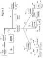
- FIG. 1is a diagram of an exemplary power distribution system with which the present invention may be employed
- FIG. 2is a diagram of a portion of an example power line communications system with which an example embodiment of the present invention may be used;
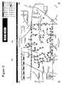
- FIG. 3is an illustration of an example Network Circuit Screen according to an example embodiment of the present invention.
- FIG. 4is an illustration of an Element Screen according to an example embodiment of the present invention.
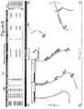
- FIG. 5is an illustration of an Element Performance Screen, in accordance with an example embodiment of the present invention.
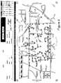
- FIG. 6is an illustration of a Device Screen according to an example embodiment of the present invention.
- FIG. 1illustrates an example power distribution systems that includes components for power generation 100 , power transmission 110 , and power delivery 130 , 150 .
- a power generation source 100generates a voltage and a transmission substation increases this voltage to high voltage (HV) levels for long distance transmission on HV transmission lines 110 to a substation transformer 120 .
- HVhigh voltage
- Typical voltages found on HV transmission lines 110range from 69 kilovolts (kV) to in excess of 800 kV.
- power distribution systemsinclude medium voltage (MV) power lines 130 and low voltage (LV) power lines 150 .
- MVtypically ranges from about 1000 V to about 100 kV
- LVtypically ranges from about 100 V to about 480 V.
- Transformersare used to convert between the respective voltage portions, e.g., between the HV section and the MV section and between the MV section and the LV section. Transformers have a primary side for connection to a first voltage (e.g., the MV section) and a secondary side for outputting another (usually lower) voltage (e.g., the LV section).
- Such transformersare often referred to as distribution transformers or a step down transformers, because they “step down” the voltage to some lower voltage.
- Transformerstherefore, provide voltage conversion for the power distribution system.
- poweris carried from a substation transformer 120 to a distribution transformer 140 over one or more MV power lines 130 .
- Poweris carried from the distribution transformer 140 to the customer premises via one or more LV power lines 150 .
- a distribution transformer 140may function to distribute one, two, three, or more phase power signals to the customer premises 160 , depending upon the demands of the user. In the United States, for example, these local distribution transformers typically feed anywhere from one to ten homes, depending upon the concentration of the customer premises in a particular area. Distribution transformers 140 may be pole-top transformers located on a utility pole, pad-mounted transformers located on the ground, or transformers located under ground level.
- FIG. 2An example PLCS is shown in FIG. 2 that includes one or more network elements (NE) or communications devices, which may include transformer bypass devices (BD) 190 and backhaul points (BP) 170 .
- NEnetwork elements
- BDtransformer bypass devices
- BPbackhaul points
- a PLCS subnetmay be defined as the part of a PLCS served by a single backhaul point 170 .
- bypass device 190is the gateway between the LV power line subnet (i.e., the LV power lines 150 and the devices that are communicatively coupled to the LV power lines 150 ) and the MV power line 130 .
- the bypass device 190may provide communications services for user computers 220 or other devices at customer premises 160 , which services may include security management, routing of Internet protocol (IP) packets, filtering data, access control, service level monitoring, signal processing and modulation/demodulation of signals transmitted over the power lines.
- IPInternet protocol
- the PLCS subnetalso includes a backhaul point 170 .
- the backhaul point 170is an interface and gateway between the MV power line 130 and a non-power line telecommunications network.
- One or more backhaul points 170typically are communicatively coupled to an aggregation point (AP) 180 , which may be co-located to a point of presence (POP) to the Internet.
- AP 180may be connected to the POP and/or Internet remotely and in any suitable manner.
- the backhaul point 170may be connected to the AP 180 using any available mechanism, including fiber optic conductors, T-carrier, Synchronous Optical Network (SONET), or wireless techniques.
- SONETSynchronous Optical Network
- the backhaul point 170includes a transceiver suited for communicating through the non-power line telecommunications medium (hereinafter the “backhaul link”).
- the backhaul point 170is also coupled to the MV power line 130 to transmit and receive communication signals on the MV power line 130 .
- LV and MV repeatersAnother type of NE that may be found in the PLCS but not shown in FIG. 2 , are LV and MV repeaters. These devices are found on power lines and receive and repeat the communication signals found on the power lines to extend the range of communications.
- the PLCSalso may include a power line server (PLS) that is a computer system with memory for storing a database of information about the PLCS and includes a network element manager (NEM) that monitors and controls the PLCS.
- PLSallows network operations personnel to provision users and network equipment, manage customer data, and monitor system status, performance and usage.
- the PLSmay reside at a remote network operations center (NOC), and/or at a PLCS Point of Presence (POP), to oversee a group of communication devices via the Internet.
- NOCremote network operations center
- POPPoint of Presence
- the PLSmay provide an Internet identity to the network devices by assigning the devices (e.g., user devices, BDs 100 , (e.g., the LV modems and MV modems of BDs), BPs 170 , and AP 180 ) IP addresses and storing the IP addresses and other device identifying information (e.g., the device's location, address, serial number, etc.) in its memory.
- the PLSmay approve or deny user devices authorization requests, command status reports, statistics and measurements from the BDs, and BPs, and provide application software upgrades to the communication devices (e.g., BDs, BPs, and other devices).
- the PLScollects and stores electric power distribution information.
- the systemuses that data to interface with utilities' back-end computer systems and may provide enhanced power distribution services such as automated meter reading, outage detection, restoration detection, load balancing, distribution automation, Volt/Volt-Amp Reactance (Volt/VAr) management, and other similar functions.
- the PLSalso may be connected to one or more APs and/or core routers directly or through the Internet and therefore can communicate with any of the BDs, user devices, and BPs through the respective AP and/or core router.
- the PLS and its network elementsmay communicate with each other through two types of communications: 1) PLS Commands and responses therefrom, and 2) BD Alerts and Alarms.
- TCP packetsare used to communicate commands and responses in the current embodiment.
- the commandstypically are initiated by the NE portion of the PLS.
- Responses sent by the BD 190may be in the form of an acknowledgement (ACK) or negative acknowledgement (NACK), or a data response depending on the type of command received by the BD 190 .
- These commandsmay include altering configuration information, synchronizing the time of the network element with that of the PLS, controlling measurement intervals (e.g., MV and/or LV voltage measurements), scheduling measurements, requesting transmission of measurement or data statistics, requesting the status of user device activations, and requesting reset or other system-level commands. Any or all of these commands may require a unique response from the network element, which is transmitted by the device and received and stored by the PLS.
- measurement intervalse.g., MV and/or LV voltage measurements
- scheduling measurementse.g., requesting transmission of measurement or data statistics, requesting the status of user device activations, and requesting reset or other system-level commands. Any or all of these commands may require a unique response from the network element, which is transmitted by the device and received and stored by the PLS.
- a power line modemmay be connected to or integrated into a smart utility meter such as a gas meter, electric meter, or water meter.
- the meterat the command of the system, may be assigned an IP address by the PLCS (e.g., by the PLS) and, upon receiving a request or at predetermined intervals, transmit data such as consumption data to the BD 100 , the system, and/or a utility computer system in a manner described herein, thereby eliminating the need to have utility personnel physically travel to read the meter.
- one or more addressable switcheswhich may form part of a utility meter, may be controlled via the PLCS (e.g., with commands transmitted from the BD 100 , the PLS, the system, and/or utility computer system) to permit connection and disconnection of gas, electricity, and/or water to the customer premises.
- PLCSe.g., with commands transmitted from the BD 100 , the PLS, the system, and/or utility computer system
- the PLCSmay be used to monitor and control reclosers, MV power line switches, direct load control devices, and other such devices.
- the addressable MV power line switchmay be a motorized switch and assigned an IP address by the PLS, which is also provided to the utility computer system to thereby operate the switch.
- the utility companymay remotely operate one or more addressable MV power line switches to provide power to the area where the outage is detected by transmitting commands to the IP addresses of the switches.
- the PLCSmay be used to monitor and operate a capacitor bank switch that inserts or removes a capacitor (or capacitor bank) into the power distribution system.
- Capacitor banksare used to improve the efficiency of the power distribution network by providing Volt/VAr management (e.g., modifying the reactance of the power distribution network).
- the PLSmay assign an IP address to one or more capacitor bank switches, which is also provided to the utility computer system to thereby operate the switch. Based on power quality measurements taken and received from one or more BDs 100 , the utility company may insert or remove one or more capacitor banks by remotely actuating one or more capacitor bank switches by transmitting commands to the IP addresses of the switches.
- the capacitor switch and the MV power line switchmay be controlled by an embodiment of the present invention that includes an MV interface and controller.
- an LV interfacemay also be employed.
- the BD 100typically transmits the data to (and receives the data from) the backhaul point 10 , which, in turn, transmits the data to (and receives the data from) the AP 20 .
- the AP 20then transmits the data to (and receives the data from) the appropriate destination (perhaps via a core router), which may be a network destination (such as an Internet address) in which case the packets are transmitted to, and pass through, numerous routers (herein routers are meant to include both network routers and switches) in order to arrive at the desired destination.
- the present inventionmay receive data in any suitable manner such as via a PLCS.
- the data presented by the system to the usermay be data collected via a PLCS including, but not limited to, the PLCS described above.
- the systemmay retrieve the data, process the data, format the data, and display the data. In some instances, the data need not be processed or formatted but is simply displayed as raw data.
- voltage measurements of both the first and second LV energized conductorsmay be taken by the network element (e.g., a BD 190 or repeater) that is installed at the transformer (e.g., on the same pole in the case of overhead distribution networks or at or near the transformer enclosure for underground residential distribution systems).
- datamay be provided from electronic power usage meters that may be installed at or near the customer premises. Such data may be transmitted from the meter via the PLCS to the PLS, the system, or other system for storage in a database to be accessed via the system.
- the datamay be communicated to a computer for storage in a database, at least in part, via a PLCS which may include transmission over the power lines (e.g., MV and/or LV power lines), wireless transmissions (e.g., via an IEEE 802.11 protocol, IEEE 802.16 (WiMAX) protocol, etc.), a combination thereof, and/or any other suitable communications means (e.g., wireless collection via a roaming collection vehicle).
- the data used by the present inventionmay be collected via any mechanism suitable for the collection of the necessary data.
- the present inventionprovides a visualization system for monitoring performance data of an electrical power distribution network.
- the performance datamay data relating to current measurements, voltage measurements, power quality management measurements, noise measurements, temperature measurements (e.g., transformer temperature), power usage data, and configuration data (e.g., whether a recloser, switch, direct load control device, capacitor bank or other element is open or closed and other such status information).
- the systemmay include a computer system and either have access to, or include a memory storing, a database of electrical power distribution network data and associated performance data.
- the computer systemmay be a conventional Windows® based computer system and include a central processing unit (CPU), a video display monitor, a keyboard, a mouse, a microphone, and an audio output device.
- CPUcentral processing unit
- the systemis controlled via a software program that is stored in memory and/or on a compact disk or other tangible medium and that is executed by the computer system's CPU.
- the software programis executable to cause the computer system to display one or more screens on the video display monitor that include diagrams and/or data of EPDN performance data.
- the screensmay be displayed in a hyper text markup language (HTML) browser such as Internet Explorer® or via any other suitable display method.
- HTTPhypertext transfer protocol
- the databasemay be stored locally (in the computer system used by the user) or may be external and, therefore, may be nearby (i.e., in the same building or room) or may be remote in which case it may be accessed via the Internet or other suitable communications channel.
- the EPDNmay include various elements such as transformers, substations, power meters, cut-outs, reclosers, arrestors, switch banks, direct load control devices, capacitor banks, and others (collectively referred to herein as “EPDN Elements”).
- the databasemay store information such as the transformer identification (ID), substation ID, cut-out ID, power meter ID, direct load control device ID, recloser ID, arrestor ID, switch bank ID, and capacitor bank ID.
- IDtransformer identification
- the databasealso may include the physical structure to which the element is mounted or otherwise associated.
- the databasealso may store a location such as a longitude and latitude.
- a transformermay be mounted to different structures which may include a utility pole, a ground level pad, or underground pad.
- the databasemay store structure information including a structure ID (e.g., pole number or pad number) for those elements, such as transformers, associated with a structure.
- structure IDe.g., pole number or pad number
- the databasemay store the premise IDs, customer names, and service addresses served by that distribution transformer.
- the usermay access the system locally or remotely via a dial up, via the Internet, via a wireless link, or in any other fashion such as, for example, via a virtual private network (VPN) connection over the Internet.
- VPNvirtual private network
- the video display monitor and user input devicesmay be remote from the remainder of the computer system.
- the software program controlling execution of the inventionmay be remote from the user or distributed (e.g., a portion executing on the user's local computer and a portion executing on the remote system computer).
- the usermay be required to log in by providing a username and password before being permitted to access the EPDN information.
- the usermay request a search and supply an input, which may include a transformer ID, Circuit information, or a pole ID.
- the systemmay search the data base for the record(s) associated with the transformer ID, Circuit information, or pole ID supplied by the user and display the retrieved information.
- the systemmay display an Element Screen, which is described in more detail below.
- the systemmay display a Network Circuit Screen as described below.
- a network circuitis meant to include at least a portion of a medium voltage power line and at least one LV power line subnet, but typically may include a plurality of LV subnets.
- the usermay supply customer information, such as the customer name, customer ID, service address, or premise code.
- customer informationsuch as the customer name, customer ID, service address, or premise code.
- the systemwill search the database for the record associated with the supplied customer information and display the retrieved information on the video monitor, which may include voltage measurements and power usage information of the customer (or customer premises) over a predetermined or user selected period of time.
- the usermay elect to view a list of some or all of the network circuits and may then select (by clicking on the link) to display the Network Circuit Screen of any network circuit in the list.
- the systemmay retrieve the information associated with the selected network circuit and use the retrieved information to generate and display the Network Circuit Screen of the network circuit.
- FIG. 3illustrates an example Network Circuit Screen 300 according to one embodiment of the present invention.
- the Network Circuit Screen 300may include a network circuit diagram 301 comprising a map that includes streets, roads, highways, and other such manmade or natural pathways (collectively hereinafter referred to as “thoroughfares”).
- the network circuit diagram 301may also include a plurality of indicia representing distribution transformers.
- the indicia representing transformersis a white “T” superimposed on a colored circle.
- the relative positions of the transformer indicia in the network circuit diagram 301substantially correspond to the positions of the transformers in the network circuit.
- the relative positions of the transformer indicia on the map in the network circuit diagram 301substantially correspond to the positions of the transformers relative to the thoroughfares and other geography represented on the map. Because the map of this example embodiment may include the thoroughfare names, the locations of the transformers may be located even without other information (e.g., longitude and latitude information). Other embodiments of the network diagram circuit 301 , however, may not include a map with street names or any map at all.
- the edges of this example embodiment of the network circuit diagram 301are a plurality of selectable arrows that, upon the selection by the user, will cause the system to redisplay a new portion of the map and network circuit located in the direction of the selected arrow.
- the usermay provide an input that causes the system to display a larger (zoom out) or smaller (zoom in) portion of the network circuit and map.
- the plurality of transformer indiciaalso may be coded (e.g., color or shape coded) to indicate a selected performance parameter value(s) for each of the plurality of distribution transformers based on the most recently collected data.
- the selected performance valueis the voltage measured on the two low voltage energized conductors. In this embodiment, if the voltage on either low voltage energized conductor is below a first threshold voltage, the circle on which the white “T” is superimposed may be color coded blue. If the voltage on either low voltage energized conductor is above a second threshold voltage, the indicia may be color coded red.
- the indiciamay be color coded green. If the system is not able to determine the selected performance parameter value (e.g., because no data exists in the database), the indicia may be coded as a gray square.
- Other embodiments or screensmay include indicia representing other EPDN elements and that are coded to represent performance information as well.
- the usercan quickly determine the EPDN elements that satisfy a predetermined condition (e.g., within a voltage range, current range, switch open, etc.) for a performance parameter. In this example, the user may view the network circuit diagram 301 to identify those transformers that are working within normal voltage range, those that are not, and those for which there is no data.
- the above exampleprovides performance information to the user that represents the most recently collected data, which may be real-time.
- the network circuit diagram 301 , and associated performance informationalso may be displayed for any time period as selected by the user. For example, the user may request and be presented performance information for the current day, the previous day, the previous month, any month, any year, or any other time period.
- the systemwill access the database and compare the voltage measurements of the low voltage energized conductors for that time period to the threshold voltages. The system may then display the selected performance data for that time period.
- the systemmay access the voltage data for the transformers in the network circuit diagram and compare the voltage measurement data of January to the two threshold voltages and display the color coded indicia to indicate if, at any time during the month of January, either low voltage energized conductor was above or below the first and/or second thresholds, respectively, or whether the both conductors were within normal operating.
- the color coded indiciamay be presented as described above. Additionally, if the voltages of either low voltage power line conductors were both below the first threshold and above the second threshold during the time period, the indicia may be color coded purple.
- the network circuit diagram 301may also include indicia representing substations (“U”), cut-outs (“C”), reclosers (“R”), arrestors (“L”), switch banks (“W”), switch bank/arrestor combination (“S”), power meters (“M”), direct load control devices (“D), and capacitor banks (“P”).
- each of these indiciamay coded (e.g., shape and/or color coded) to provide performance data about the EPDN element.
- the indicia for each recloser (“R”)may be color coded red when the recloser is open and color coded blue when the recloser is closed.
- the Network Circuit Screen 300may include a calendar. The user may select any day, week, month, year, or other time period for which to request information by clicking on portions of the calendar. In response, the system may re-display the existing screen with new data for the selected time or time period.
- the transformer Element Screen 400may include a header 401 that provides the transformer ID, and product information of the selected transformer such as the transformers rating (50 KVA) and the type of transformer (e.g., single phase).
- the header 401may disclose information relating to the structure to which the selected transformer is mounted (e.g., Pole: MO-129), the number of premises served (e.g., 5), and the MV phase to which the transformer is connected (e.g., A, B, or C).
- the header 401may also include any comments or memos (under the heading Note) and the type of insulation (under “Prot:”).
- the Element Screen 400may include the network circuit diagram with the selected indicia hi-lighted such as, for example, a circle 451 around the selected indicia.
- the Element Screen 400may also include a link 405 , which the user may select to view an Element Performance Screen 500 .
- the Element Performance Screen 500may include a header 501 and more detailed performance information of the EPDN element over a time period.
- This example of an Element Performance Screen 500 of a transformerincludes a voltage plot 530 that graphically displays the voltage measured on each of the two LV energized conductors of the selected transformer over time.
- the voltage plot 530may also display an upper limit 531 and a lower limit 532 , which are 126V and 114V in the example voltage plot. By plotting the voltage over time and also displaying the limits, the user can quickly identify those times or time periods when the voltage on either energized conductor was above or below the respective threshold voltages.
- the voltage plot 530may also display a median voltage ( 533 and 534 ) for each LV energized conductor of the selected distribution transformer for the time period.
- the data used to calculate the median voltages and plot the voltages of the voltage plot 530may be displayed in a voltage chart 550 , which lists a date and time associated with the voltage measurements for the two LV energized conductors.
- the usermay scroll up or down through the chart 550 , which also hi-lights the highest and lowest voltage measurement of each LV energized conductor.
- the voltage chart 550may display data for each measurement provided by the PLCS, every other measurement, every third measurement, or some other portion of the measurements provided as requested by the user. For example, if the user wanted to review the performance data (i.e., voltage measurements) of the transformer for a year, the chart 550 might show daily measurements, daily averages, or daily mean values.
- the chart 550might show measurements taken each fifteen minutes, thirty minutes, five minutes, or averages or mean values for such time periods.
- the useralso may download the data in the voltage chart by clicking on the “Export” button, which will cause the data to be saved to a file on the local computer.
- the transformer Element Performance Screen 500may also include a summary chart 570 , which may display the Mean, mode, median, minimum, and maximum voltages for each LV energized conductor over the time period.
- a summary chart 570may display the Mean, mode, median, minimum, and maximum voltages for each LV energized conductor over the time period.
- the maximum or minimum voltage of either LV conductoris above or below the respective limit during the time period, the percentage above the upper limit and percentage below the lower limit may also be displayed.
- the usermay select the minimum voltage or maximum voltage of either LV conductor by clicking on the value displayed in the summary chart 570 , which will cause the voltage chart 550 to automatically scroll to a position to display the selected voltage (and date and time) in the voltage chart 550 .
- the usermay select the Served button, which may cause a new window (browser) to open (not shown) displaying information relating to the LV subnet of the transformer.
- the LV subnet informationmay include the number of premises served, the addresses of the premises served, the customer names of the customer served, and the premise code of the premises served.
- this datamay be represented graphically with the serving transformer and meters represented by color coded indicia.
- the Devices Screen 600may include a device list 601 and a device diagram 650 .
- the device diagrammay include indicia representing the various EPDN elements superimposed on a map and in relative positions to each other and the thoroughfares therein (as described above for the network circuit diagram 301 ). Again, the EPDN elements may be color coded as described above.
- the map (and view of the EPDN elements)is sized so that only indicia of EPDN elements within a selected (or predetermined) proximity of the selected transformer (or element) are displayed.
- the usermay select any of the buttons labeled 500, 1000, 1500, or 2000 and the device diagram 650 may display (i.e., redisplay) re-sized so that only those elements within 500, 1000, 1500, or 2000 feet, respectively, of the selected transformer (or element) are displayed.
- the example device diagram 650 of FIG. 6depicts the elements (and map) that are within one thousand feet of the selected transformer.
- the Device Screen 600includes a device list 601 , which may include a list of devices that are present in the device diagram 650 and within the selected distance of the selected EPDN element. Thus, as the user selects different distances, the device list 601 will also change (increase or decrease) to shown only those EPDN elements with the selected distance. For each device, the device list 601 may also include the distance to the selected transformer (or element), a device ID, the phase to which the device is connected, the type of device, the structure ID to which the device is mounted, the operating voltage of the device (if appropriate), the rated voltage, the operating voltage of the device, any comments from the database (under “Note”), the type of protection (under “U1 Protection”), and the facility type (which may indicate the number of phases).
- the device list 601may also include the distance to the selected transformer (or element), a device ID, the phase to which the device is connected, the type of device, the structure ID to which the device is mounted, the operating voltage of the device (if appropriate), the rated voltage, the
- the useralso may click on any element in the device diagram 650 and the Device Screen 600 will refresh to display the EPDN elements within the selected distance of the selected element.
- the useralso may click on any element in the device list 601 and the Device Screen 600 will refresh to display the EPDN elements within the selected distance of the selected element.
- a usercan cause a high resolution satellite image to be superimposed over the map to allow for the determination of relative placement of elements. Additionally, such a representation of the actual structures being served allows for more succinct decision making by the user based on the type of structure (e.g., commercial or residential) and the relative size of the displayed structures.
- Alternate embodiments of the present inventionmay include viewer or additional screens that present different information.
- the network circuit diagrams and/or device diagrams of other embodimentsmay additionally depict the medium voltage power lines, the customer premises, the PLCS fiber optic backhaul links, and/or the low voltage power lines.
- the systemmay provide one or more links that opens one or more browsers or other windows that receive video data from a video camera, which may provide video data of a substation or other EPDN element.
- the cameramay also be controlled to zoom in, zoom out, and pan in response to commands from the system.
- EPDN performance datamay also be presented to the user.
- the customer premisesmay be represented by indicia on a diagram coded to indicate the power used by the premises.
- the systemmay display the voltage data and indicia (indicating above, below, or within threshold voltages) of the customer premises, which data may be provided by a power usage meter.
- power quality informationmay be presented to the user for each distribution transformer via coded indicia.
- the systemmay search and display information of the number of transformers in a given area with output voltages over the threshold voltage and under the threshold at any selected point in time or over any selected period of time. The system may also display information indicating power theft as well.
Landscapes
- Engineering & Computer Science (AREA)
- Physics & Mathematics (AREA)
- General Physics & Mathematics (AREA)
- Automation & Control Theory (AREA)
- Human Computer Interaction (AREA)
- Remote Monitoring And Control Of Power-Distribution Networks (AREA)
Abstract
Description
Claims (33)
Priority Applications (3)
| Application Number | Priority Date | Filing Date | Title |
|---|---|---|---|
| US11/114,024US7627453B2 (en) | 2005-04-26 | 2005-04-26 | Power distribution network performance data presentation system and method |
| US12/613,345US8090556B2 (en) | 2005-04-26 | 2009-11-05 | Power distribution network performance data presentation system and method |
| US13/308,181US20120072142A1 (en) | 2005-04-26 | 2011-11-30 | Power Distribution Network Performance Data Presentation System and Method |
Applications Claiming Priority (1)
| Application Number | Priority Date | Filing Date | Title |
|---|---|---|---|
| US11/114,024US7627453B2 (en) | 2005-04-26 | 2005-04-26 | Power distribution network performance data presentation system and method |
Related Child Applications (1)
| Application Number | Title | Priority Date | Filing Date |
|---|---|---|---|
| US12/613,345ContinuationUS8090556B2 (en) | 2005-04-26 | 2009-11-05 | Power distribution network performance data presentation system and method |
Publications (2)
| Publication Number | Publication Date |
|---|---|
| US20060238364A1 US20060238364A1 (en) | 2006-10-26 |
| US7627453B2true US7627453B2 (en) | 2009-12-01 |
Family
ID=37186293
Family Applications (3)
| Application Number | Title | Priority Date | Filing Date |
|---|---|---|---|
| US11/114,024Expired - Fee RelatedUS7627453B2 (en) | 2005-04-26 | 2005-04-26 | Power distribution network performance data presentation system and method |
| US12/613,345Expired - Fee RelatedUS8090556B2 (en) | 2005-04-26 | 2009-11-05 | Power distribution network performance data presentation system and method |
| US13/308,181AbandonedUS20120072142A1 (en) | 2005-04-26 | 2011-11-30 | Power Distribution Network Performance Data Presentation System and Method |
Family Applications After (2)
| Application Number | Title | Priority Date | Filing Date |
|---|---|---|---|
| US12/613,345Expired - Fee RelatedUS8090556B2 (en) | 2005-04-26 | 2009-11-05 | Power distribution network performance data presentation system and method |
| US13/308,181AbandonedUS20120072142A1 (en) | 2005-04-26 | 2011-11-30 | Power Distribution Network Performance Data Presentation System and Method |
Country Status (1)
| Country | Link |
|---|---|
| US (3) | US7627453B2 (en) |
Cited By (21)
| Publication number | Priority date | Publication date | Assignee | Title |
|---|---|---|---|---|
| US20080109387A1 (en)* | 2006-11-02 | 2008-05-08 | Deaver Brian J | Power Theft Detection System and Method |
| US20090184835A1 (en)* | 2008-01-20 | 2009-07-23 | Deaver Sr Brian J | System, Device and Method For Providing Power Outage and Restoration Notification |
| US20100049472A1 (en)* | 2005-04-26 | 2010-02-25 | Keefe R Anthony | Power Distribution Network Performance Data Presentation System and Method |
| US20110071697A1 (en)* | 2010-10-06 | 2011-03-24 | William Vincent Torre | Smart transformer |
| US20120026005A1 (en)* | 2010-07-29 | 2012-02-02 | Korea Electric Power Corporation | Automatic meter reading system and method for underground distribution line using wired/wireless communication |
| US20120203388A1 (en)* | 2011-02-08 | 2012-08-09 | Avista Corporation | Outage Management Algorithm |
| US20130006434A1 (en)* | 2011-06-28 | 2013-01-03 | General Electric Company | Control system for an electric power system |
| US20130219279A1 (en)* | 2012-02-21 | 2013-08-22 | Ambient Corporation | Aggregating nodes for efficient network management system visualization and operations |
| US20140210839A1 (en)* | 2007-07-26 | 2014-07-31 | Alstom Grid Inc. | Methods for assessing potentially compromising situations of a utility company |
| US8929585B2 (en) | 2010-11-30 | 2015-01-06 | International Business Machines Corporation | Hazard detection for asset management |
| US8928489B2 (en) | 2011-02-08 | 2015-01-06 | Avista Corporation | Ping server |
| US9322669B2 (en) | 2005-10-28 | 2016-04-26 | Electro Industries/Gauge Tech | Intelligent electronic device having audible and visual interface |
| US9403441B2 (en) | 2012-08-21 | 2016-08-02 | Cooper Technologies Company | Autonomous management of distribution transformer power load |
| US20170098352A1 (en)* | 2015-10-01 | 2017-04-06 | Honeywell International Inc. | System and method of providing intelligent system trouble notifications using localization |
| US10330713B2 (en) | 2012-12-21 | 2019-06-25 | Electro Industries/Gauge Tech | Intelligent electronic device having a touch sensitive user interface |
| US10489019B2 (en) | 2017-06-16 | 2019-11-26 | Florida Power & Light Company | Identifying and presenting related electrical power distribution system events |
| US10814893B2 (en) | 2016-03-21 | 2020-10-27 | Ge Global Sourcing Llc | Vehicle control system |
| US10837995B2 (en) | 2017-06-16 | 2020-11-17 | Florida Power & Light Company | Composite fault mapping |
| US10852341B2 (en) | 2017-06-16 | 2020-12-01 | Florida Power & Light Company | Composite fault mapping |
| US11072356B2 (en) | 2016-06-30 | 2021-07-27 | Transportation Ip Holdings, Llc | Vehicle control system |
| US12072210B2 (en) | 2005-10-28 | 2024-08-27 | Ei Electronics Llc | Electronic power meter having an end user customizable display |
Families Citing this family (36)
| Publication number | Priority date | Publication date | Assignee | Title |
|---|---|---|---|---|
| US7626497B2 (en)* | 2005-05-25 | 2009-12-01 | Current Technologies, Llc | Power line communication vegetation management system and method |
| US7508834B2 (en)* | 2005-06-21 | 2009-03-24 | Current Technologies, Llc | Wireless link for power line communications system |
| US7421352B2 (en)* | 2006-04-10 | 2008-09-02 | Square D Company | Network-enabled electrical power equipment with integrated content management system |
| CN101682179B (en)* | 2007-03-14 | 2015-09-16 | 佐尼特结构解决方案有限责任公司 | Nema outlets and the network be associated of intelligence |
| US11316368B2 (en) | 2007-03-14 | 2022-04-26 | Zonit Structured Solutions, Llc | Premises power usage monitoring system |
| EP2101394A1 (en)* | 2008-03-10 | 2009-09-16 | ABB Research Ltd. | Distribution controller |
| BRPI0819935B1 (en)* | 2007-12-12 | 2019-01-08 | Abb Research Ltd | method of restoring power in a power distribution network |
| US8000913B2 (en)* | 2008-01-21 | 2011-08-16 | Current Communications Services, Llc | System and method for providing power distribution system information |
| US8195337B2 (en)* | 2008-04-14 | 2012-06-05 | Cruickshank Iii Robert F | Method and apparatus for orchestrating utility power supply and demand in real time using a continuous pricing signal sent via a network to home networks and smart appliances |
| US8326892B2 (en)* | 2008-05-30 | 2012-12-04 | Schneider Electric USA, Inc. | Methods and systems for automatic conversion of a utility monitoring system layout into a storage format |
| US8548607B1 (en)* | 2008-11-03 | 2013-10-01 | Autani Corp. | Automation system network management, architectures, and methods and applications thereof |
| CN102395933B (en) | 2009-04-17 | 2014-10-29 | Abb研究有限公司 | Power grid visualization |
| US8838282B1 (en)* | 2009-11-16 | 2014-09-16 | Comverge, Inc. | Method and system for providing a central controller that can communicate across heterogenous networks for reaching various energy load control devices |
| US9497092B2 (en)* | 2009-12-08 | 2016-11-15 | Hand Held Products, Inc. | Remote device management interface |
| CN102668579A (en)* | 2010-10-05 | 2012-09-12 | 英特尔公司 | Method and apparatus for dynamically adjusting video quality |
| WO2012051460A2 (en)* | 2010-10-15 | 2012-04-19 | Gridspeak Corporation | Systems and methods for automated availability and/or outage management |
| US9000945B2 (en) | 2010-11-23 | 2015-04-07 | Corinex Communications Corp. | System and method for communicating over power lines |
| US9477932B2 (en)* | 2011-01-17 | 2016-10-25 | General Electric Company | System and method for providing visualization of a parameter on multiple branches of a distribution network |
| US8812167B2 (en)* | 2011-04-19 | 2014-08-19 | General Electric Company | Volt/var switch plan |
| US8769345B2 (en)* | 2011-07-29 | 2014-07-01 | General Electric Company | Computing device and methods of presenting data to identify faults within power systems |
| CN102623975B (en)* | 2012-04-01 | 2014-04-23 | 许继电气股份有限公司 | Generalized Node Generation Method for Current Differential Protection Based on Electrical Topology of Regional Distribution Network |
| EP2905868B1 (en) | 2012-10-01 | 2018-08-08 | Fujitsu Limited | Power distribution management device, display control method, and display control program |
| WO2014054105A1 (en)* | 2012-10-01 | 2014-04-10 | 富士通株式会社 | Power distribution management device, power distribution management method, and power distribution management program |
| US9250674B2 (en)* | 2013-01-18 | 2016-02-02 | General Electric Company | Methods and systems for restoring power based on forecasted loads |
| ES2931950T3 (en)* | 2013-02-06 | 2023-01-05 | Schneider Electric Usa Inc | Generation of one-line electrical network diagrams |
| CN103559657A (en)* | 2013-11-19 | 2014-02-05 | 国家电网公司 | Electric transmission line data processing method and system |
| WO2015092911A1 (en)* | 2013-12-20 | 2015-06-25 | 株式会社日立製作所 | Power system data display device and method |
| US10614531B2 (en)* | 2014-04-11 | 2020-04-07 | S&C Electric Company | Filter-based dynamic power system operation dashboards |
| US9859754B2 (en)* | 2014-05-08 | 2018-01-02 | Vertiv Energy Systems, Inc. | Computer systems and computer-implemented methods for warning users of overload conditions in power distribution systems |
| EP3129842B1 (en)* | 2014-05-28 | 2019-07-17 | Siemens Aktiengesellschaft | Method and control-center apparatus for monitoring an installation |
| ES2947504T3 (en)* | 2016-11-08 | 2023-08-10 | Abb Spa | A computer-implemented method for configuring electronic relays in an electrical power distribution network |
| CN108321925B (en)* | 2017-01-18 | 2023-06-30 | 孙麓轩 | Monitoring method and system for low-voltage power distribution system |
| DE102018114181A1 (en)* | 2018-02-27 | 2019-08-29 | Dehn + Söhne Gmbh + Co. Kg | Method for assessing the condition and quality of low-voltage networks |
| CN108765188A (en)* | 2018-05-02 | 2018-11-06 | 深圳供电局有限公司 | Graphical real-time energy efficiency monitoring system |
| US11824650B2 (en)* | 2020-09-10 | 2023-11-21 | Fisher-Rosemount Systems, Inc. | Publish-subscribe communication architecture for highly-versatile field devices in control and automation systems |
| WO2023004699A1 (en)* | 2021-07-29 | 2023-02-02 | 西门子股份公司 | Method and apparatus for presenting data integrity of transformer, and storage medium |
Citations (69)
| Publication number | Priority date | Publication date | Assignee | Title |
|---|---|---|---|---|
| US1790024A (en) | 1926-03-02 | 1931-01-27 | American Brown Boveri Electric | Device for determining the condition of transformers |
| US3445814A (en) | 1963-03-25 | 1969-05-20 | Electrometre Sa | System for interrogating remote stations via power lines of an electrical distribution network |
| US3656112A (en) | 1969-03-14 | 1972-04-11 | Constellation Science And Tech | Utility meter remote automatic reading system |
| US3900842A (en)* | 1973-03-29 | 1975-08-19 | Automated Technology Corp | Remote automatic meter reading and control system |
| US3942168A (en) | 1975-01-31 | 1976-03-02 | Westinghouse Electric Corporation | Distribution network power line communication system |
| US3967264A (en) | 1975-01-31 | 1976-06-29 | Westinghouse Electric Corporation | Distribution network power line communication system including addressable interrogation and response repeater |
| US3973087A (en)* | 1974-12-05 | 1976-08-03 | General Electric Company | Signal repeater for power line access data system |
| US3973240A (en) | 1974-12-05 | 1976-08-03 | General Electric Company | Power line access data system |
| US4119948A (en) | 1976-04-29 | 1978-10-10 | Ernest Michael Ward | Remote meter reading system |
| US4442492A (en) | 1979-08-21 | 1984-04-10 | Karlsson Bjoern G E | Device for central reading and registration of customers' power consumption |
| US4652855A (en) | 1984-12-05 | 1987-03-24 | Westinghouse Electric Corp. | Portable remote meter reading apparatus |
| US4654806A (en) | 1984-03-30 | 1987-03-31 | Westinghouse Electric Corp. | Method and apparatus for monitoring transformers |
| US4878142A (en)* | 1987-09-16 | 1989-10-31 | Asea Brown Boveri Ab | High resistance ground fault protection |
| US5056107A (en) | 1990-02-15 | 1991-10-08 | Iris Systems Inc. | Radio communication network for remote data generating stations |
| EP0581351A1 (en) | 1992-07-24 | 1994-02-02 | ITALTEL SOCIETA ITALIANA TELECOMUNICAZIONI s.p.a. | Transceiver for the exchange of informations along lines for the transport of electric power |
| US5426360A (en) | 1994-02-17 | 1995-06-20 | Niagara Mohawk Power Corporation | Secondary electrical power line parameter monitoring apparatus and system |
| US5448229A (en) | 1992-12-28 | 1995-09-05 | General Electric Company | Method and apparatus for communicating with a meter register |
| US5568399A (en)* | 1995-01-31 | 1996-10-22 | Puget Consultants Inc. | Method and apparatus for power outage determination using distribution system information |
| US5625751A (en)* | 1994-08-30 | 1997-04-29 | Electric Power Research Institute | Neural network for contingency ranking dynamic security indices for use under fault conditions in a power distribution system |
| US5696501A (en)* | 1994-08-02 | 1997-12-09 | General Electric Company | Method and apparatus for performing the register functions for a plurality of metering devices at a common node |
| US5748104A (en) | 1996-07-11 | 1998-05-05 | Qualcomm Incorporated | Wireless remote telemetry system |
| US5801643A (en) | 1996-06-20 | 1998-09-01 | Northrop Grumman Corporation | Remote utility meter reading system |
| US5805458A (en) | 1993-08-11 | 1998-09-08 | First Pacific Networks | System for utility demand monitoring and control |
| US5880677A (en) | 1996-10-15 | 1999-03-09 | Lestician; Guy J. | System for monitoring and controlling electrical consumption, including transceiver communicator control apparatus and alternating current control apparatus |
| US5892758A (en) | 1996-07-11 | 1999-04-06 | Qualcomm Incorporated | Concentrated subscriber wireless remote telemetry system |
| US6151330A (en) | 1996-12-04 | 2000-11-21 | Powercom Control Systems Ltd. | Electric power supply management system |
| US6150955A (en) | 1996-10-28 | 2000-11-21 | Tracy Corporation Ii | Apparatus and method for transmitting data via a digital control channel of a digital wireless network |
| US6239722B1 (en) | 1997-10-16 | 2001-05-29 | Cic Global, Llc | System and method for communication between remote locations |
| US6255805B1 (en) | 2000-02-04 | 2001-07-03 | Motorola, Inc. | Device for electrical source sharing |
| US6259972B1 (en)* | 1998-01-16 | 2001-07-10 | Enghouse Systems Usa, Inc. | Method for processing and disseminating utility outage information |
| US6262672B1 (en) | 1998-08-14 | 2001-07-17 | General Electric Company | Reduced cost automatic meter reading system and method using locally communicating utility meters |
| US20010010032A1 (en) | 1998-10-27 | 2001-07-26 | Ehlers Gregory A. | Energy management and building automation system |
| US20010038343A1 (en) | 1998-05-01 | 2001-11-08 | Abb Automation Inc. | Wireless area network communications module for utility meters |
| US6346875B1 (en) | 2000-01-03 | 2002-02-12 | General Electric Company | GHM aggregator |
| US6373399B1 (en) | 1990-02-15 | 2002-04-16 | Itron, Inc. | Wide area communications network for remote data generating stations |
| US20020084914A1 (en) | 1997-05-23 | 2002-07-04 | Jackson Philip L. | Revenue meter arrangement having sensors in mounting device |
| US6459998B1 (en) | 1999-07-24 | 2002-10-01 | Gary R. Hoffman | Sensing downed power lines |
| US20020147809A1 (en)* | 2000-10-17 | 2002-10-10 | Anders Vinberg | Method and apparatus for selectively displaying layered network diagrams |
| US20020161558A1 (en) | 2001-02-28 | 2002-10-31 | Bruno Georges | Transformer management system and method |
| US6504357B1 (en) | 1992-02-21 | 2003-01-07 | Abb Automation Inc. | Apparatus for metering electrical power and electronically communicating electrical power information |
| US6538577B1 (en) | 1997-09-05 | 2003-03-25 | Silver Springs Networks, Inc. | Electronic electric meter for networked meter reading |
| US20030149581A1 (en)* | 2002-08-28 | 2003-08-07 | Imran Chaudhri | Method and system for providing intelligent network content delivery |
| US6611134B2 (en) | 2000-08-02 | 2003-08-26 | Xeline Co., Ltd. | Open type electricity meter |
| US6618709B1 (en) | 1998-04-03 | 2003-09-09 | Enerwise Global Technologies, Inc. | Computer assisted and/or implemented process and architecture for web-based monitoring of energy related usage, and client accessibility therefor |
| US6684245B1 (en) | 1997-04-08 | 2004-01-27 | Elster Electricity, Llc | Automatic meter reading system employing common broadcast command channel |
| US20040036478A1 (en)* | 2002-05-06 | 2004-02-26 | Enikia L.L.C. | Method and system for power line network fault detection and quality monitoring |
| US6710721B1 (en) | 1999-10-16 | 2004-03-23 | Datamatic Inc. | Radio frequency automated meter reading device |
| US6711512B2 (en) | 2001-08-07 | 2004-03-23 | Korea Electric Power Data Network Co. Ltd. | Pole transformer load monitoring system using wireless internet network |
| US20040064276A1 (en) | 2002-10-01 | 2004-04-01 | Poweronedata Corporation | Utility power meter database |
| US20040090312A1 (en)* | 2001-10-27 | 2004-05-13 | Manis Constantine N. | Power line communication system with autonomous network segments |
| US6737984B1 (en) | 1997-08-15 | 2004-05-18 | General Electric Company | Automatic meter reading system using locally communicating utility meters |
| US20040243377A1 (en)* | 2002-12-18 | 2004-12-02 | Ilya Roytelman | Real time power flow method for distribution system |
| US20040239522A1 (en) | 2003-06-02 | 2004-12-02 | Gallagher Todd John | Remotely accessed electrical metering system |
| US20050090995A1 (en) | 2003-10-27 | 2005-04-28 | Itron Inc. | Distributed asset optimization (DAO) system and method |
| US20050096772A1 (en) | 2003-10-31 | 2005-05-05 | Cox David N. | Transformer performance prediction |
| US6954814B1 (en) | 1999-06-10 | 2005-10-11 | Amron Technologies Inc. | Method and system for monitoring and transmitting utility status via universal communications interface |
| US20050223782A1 (en) | 2004-04-07 | 2005-10-13 | Hitachi Industrial Equipment Systems Co., Ltd. | Transformer monitoring system |
| US6965303B2 (en) | 2002-12-10 | 2005-11-15 | Current Technologies, Llc | Power line communication system and method |
| US6980091B2 (en) | 2002-12-10 | 2005-12-27 | Current Technologies, Llc | Power line communication system and method of operating the same |
| US6986071B2 (en)* | 2002-02-01 | 2006-01-10 | Powerdsine, Ltd. | Detecting network power connection status using AC signals |
| US20060007016A1 (en) | 2004-07-09 | 2006-01-12 | Centerpoint Energy, Inc. | Utilities and communication integrator |
| US20060031180A1 (en) | 2004-08-03 | 2006-02-09 | Uscl Corporation | Integrated metrology systems and information and control apparatus for interaction with integrated metrology systems |
| US6998962B2 (en) | 2000-04-14 | 2006-02-14 | Current Technologies, Llc | Power line communication apparatus and method of using the same |
| US20060033454A1 (en) | 2004-08-12 | 2006-02-16 | Mathews David K | High speed data interface to the AC power line through a standard light bulb socket |
| US20060045105A1 (en) | 2004-08-25 | 2006-03-02 | Dobosz Paul J | System and method for using a utility meter |
| US20060091877A1 (en) | 2004-10-19 | 2006-05-04 | Robinson Andrew J | Method and apparatus for an electric meter |
| US20060106554A1 (en) | 2004-11-01 | 2006-05-18 | Centerpoint Energy, Inc. | Current sensing lug |
| US20060145834A1 (en) | 2000-04-14 | 2006-07-06 | Berkman William H | Automated meter reading power line communication system and method |
| US7089089B2 (en)* | 2003-03-31 | 2006-08-08 | Power Measurement Ltd. | Methods and apparatus for retrieving energy readings from an energy monitoring device |
Family Cites Families (7)
| Publication number | Priority date | Publication date | Assignee | Title |
|---|---|---|---|---|
| US4419619A (en) | 1981-09-18 | 1983-12-06 | Mcgraw-Edison Company | Microprocessor controlled voltage regulating transformer |
| US5734586A (en)* | 1995-05-05 | 1998-03-31 | Cornell Research Foundation, Inc. | System for achieving optimal steady state in power distribution networks |
| US6496342B1 (en)* | 1999-02-12 | 2002-12-17 | Bitronics Inc. | Distributed monitoring and protection system for a distributed power network |
| US6445196B1 (en) | 2000-09-25 | 2002-09-03 | Xenia Burdette White | Transformer test control device |
| US6810069B2 (en) | 2002-07-12 | 2004-10-26 | Mcgraw-Edison Company | Electrical arc furnace protection system |
| US7321291B2 (en) | 2004-10-26 | 2008-01-22 | Current Technologies, Llc | Power line communications system and method of operating the same |
| US7627453B2 (en)* | 2005-04-26 | 2009-12-01 | Current Communications Services, Llc | Power distribution network performance data presentation system and method |
- 2005
- 2005-04-26USUS11/114,024patent/US7627453B2/ennot_activeExpired - Fee Related
- 2009
- 2009-11-05USUS12/613,345patent/US8090556B2/ennot_activeExpired - Fee Related
- 2011
- 2011-11-30USUS13/308,181patent/US20120072142A1/ennot_activeAbandoned
Patent Citations (73)
| Publication number | Priority date | Publication date | Assignee | Title |
|---|---|---|---|---|
| US1790024A (en) | 1926-03-02 | 1931-01-27 | American Brown Boveri Electric | Device for determining the condition of transformers |
| US3445814A (en) | 1963-03-25 | 1969-05-20 | Electrometre Sa | System for interrogating remote stations via power lines of an electrical distribution network |
| US3656112A (en) | 1969-03-14 | 1972-04-11 | Constellation Science And Tech | Utility meter remote automatic reading system |
| US3900842A (en)* | 1973-03-29 | 1975-08-19 | Automated Technology Corp | Remote automatic meter reading and control system |
| US3973087A (en)* | 1974-12-05 | 1976-08-03 | General Electric Company | Signal repeater for power line access data system |
| US3973240A (en) | 1974-12-05 | 1976-08-03 | General Electric Company | Power line access data system |
| US3942168A (en) | 1975-01-31 | 1976-03-02 | Westinghouse Electric Corporation | Distribution network power line communication system |
| US3967264A (en) | 1975-01-31 | 1976-06-29 | Westinghouse Electric Corporation | Distribution network power line communication system including addressable interrogation and response repeater |
| US4119948A (en) | 1976-04-29 | 1978-10-10 | Ernest Michael Ward | Remote meter reading system |
| US4442492A (en) | 1979-08-21 | 1984-04-10 | Karlsson Bjoern G E | Device for central reading and registration of customers' power consumption |
| US4654806A (en) | 1984-03-30 | 1987-03-31 | Westinghouse Electric Corp. | Method and apparatus for monitoring transformers |
| US4652855A (en) | 1984-12-05 | 1987-03-24 | Westinghouse Electric Corp. | Portable remote meter reading apparatus |
| US4878142A (en)* | 1987-09-16 | 1989-10-31 | Asea Brown Boveri Ab | High resistance ground fault protection |
| US5056107A (en) | 1990-02-15 | 1991-10-08 | Iris Systems Inc. | Radio communication network for remote data generating stations |
| US6373399B1 (en) | 1990-02-15 | 2002-04-16 | Itron, Inc. | Wide area communications network for remote data generating stations |
| US6504357B1 (en) | 1992-02-21 | 2003-01-07 | Abb Automation Inc. | Apparatus for metering electrical power and electronically communicating electrical power information |
| EP0581351A1 (en) | 1992-07-24 | 1994-02-02 | ITALTEL SOCIETA ITALIANA TELECOMUNICAZIONI s.p.a. | Transceiver for the exchange of informations along lines for the transport of electric power |
| US5448229A (en) | 1992-12-28 | 1995-09-05 | General Electric Company | Method and apparatus for communicating with a meter register |
| US5805458A (en) | 1993-08-11 | 1998-09-08 | First Pacific Networks | System for utility demand monitoring and control |
| US5426360A (en) | 1994-02-17 | 1995-06-20 | Niagara Mohawk Power Corporation | Secondary electrical power line parameter monitoring apparatus and system |
| US5696501A (en)* | 1994-08-02 | 1997-12-09 | General Electric Company | Method and apparatus for performing the register functions for a plurality of metering devices at a common node |
| US5625751A (en)* | 1994-08-30 | 1997-04-29 | Electric Power Research Institute | Neural network for contingency ranking dynamic security indices for use under fault conditions in a power distribution system |
| US5568399A (en)* | 1995-01-31 | 1996-10-22 | Puget Consultants Inc. | Method and apparatus for power outage determination using distribution system information |
| US5801643A (en) | 1996-06-20 | 1998-09-01 | Northrop Grumman Corporation | Remote utility meter reading system |
| US5748104A (en) | 1996-07-11 | 1998-05-05 | Qualcomm Incorporated | Wireless remote telemetry system |
| US5892758A (en) | 1996-07-11 | 1999-04-06 | Qualcomm Incorporated | Concentrated subscriber wireless remote telemetry system |
| US5880677A (en) | 1996-10-15 | 1999-03-09 | Lestician; Guy J. | System for monitoring and controlling electrical consumption, including transceiver communicator control apparatus and alternating current control apparatus |
| US6150955A (en) | 1996-10-28 | 2000-11-21 | Tracy Corporation Ii | Apparatus and method for transmitting data via a digital control channel of a digital wireless network |
| US6151330A (en) | 1996-12-04 | 2000-11-21 | Powercom Control Systems Ltd. | Electric power supply management system |
| US6684245B1 (en) | 1997-04-08 | 2004-01-27 | Elster Electricity, Llc | Automatic meter reading system employing common broadcast command channel |
| US20020084914A1 (en) | 1997-05-23 | 2002-07-04 | Jackson Philip L. | Revenue meter arrangement having sensors in mounting device |
| US6737984B1 (en) | 1997-08-15 | 2004-05-18 | General Electric Company | Automatic meter reading system using locally communicating utility meters |
| US6538577B1 (en) | 1997-09-05 | 2003-03-25 | Silver Springs Networks, Inc. | Electronic electric meter for networked meter reading |
| US6239722B1 (en) | 1997-10-16 | 2001-05-29 | Cic Global, Llc | System and method for communication between remote locations |
| US6259972B1 (en)* | 1998-01-16 | 2001-07-10 | Enghouse Systems Usa, Inc. | Method for processing and disseminating utility outage information |
| US6618709B1 (en) | 1998-04-03 | 2003-09-09 | Enerwise Global Technologies, Inc. | Computer assisted and/or implemented process and architecture for web-based monitoring of energy related usage, and client accessibility therefor |
| US6778099B1 (en) | 1998-05-01 | 2004-08-17 | Elster Electricity, Llc | Wireless area network communications module for utility meters |
| US20010038343A1 (en) | 1998-05-01 | 2001-11-08 | Abb Automation Inc. | Wireless area network communications module for utility meters |
| US6650249B2 (en) | 1998-05-01 | 2003-11-18 | Elster Electricity, Llc | Wireless area network communications module for utility meters |
| US6262672B1 (en) | 1998-08-14 | 2001-07-17 | General Electric Company | Reduced cost automatic meter reading system and method using locally communicating utility meters |
| US20010010032A1 (en) | 1998-10-27 | 2001-07-26 | Ehlers Gregory A. | Energy management and building automation system |
| US6954814B1 (en) | 1999-06-10 | 2005-10-11 | Amron Technologies Inc. | Method and system for monitoring and transmitting utility status via universal communications interface |
| US6459998B1 (en) | 1999-07-24 | 2002-10-01 | Gary R. Hoffman | Sensing downed power lines |
| US6710721B1 (en) | 1999-10-16 | 2004-03-23 | Datamatic Inc. | Radio frequency automated meter reading device |
| US6346875B1 (en) | 2000-01-03 | 2002-02-12 | General Electric Company | GHM aggregator |
| US6255805B1 (en) | 2000-02-04 | 2001-07-03 | Motorola, Inc. | Device for electrical source sharing |
| US6998962B2 (en) | 2000-04-14 | 2006-02-14 | Current Technologies, Llc | Power line communication apparatus and method of using the same |
| US20060145834A1 (en) | 2000-04-14 | 2006-07-06 | Berkman William H | Automated meter reading power line communication system and method |
| US6611134B2 (en) | 2000-08-02 | 2003-08-26 | Xeline Co., Ltd. | Open type electricity meter |
| US20020147809A1 (en)* | 2000-10-17 | 2002-10-10 | Anders Vinberg | Method and apparatus for selectively displaying layered network diagrams |
| US20020161558A1 (en) | 2001-02-28 | 2002-10-31 | Bruno Georges | Transformer management system and method |
| US6711512B2 (en) | 2001-08-07 | 2004-03-23 | Korea Electric Power Data Network Co. Ltd. | Pole transformer load monitoring system using wireless internet network |
| US20040090312A1 (en)* | 2001-10-27 | 2004-05-13 | Manis Constantine N. | Power line communication system with autonomous network segments |
| US6986071B2 (en)* | 2002-02-01 | 2006-01-10 | Powerdsine, Ltd. | Detecting network power connection status using AC signals |
| US20040036478A1 (en)* | 2002-05-06 | 2004-02-26 | Enikia L.L.C. | Method and system for power line network fault detection and quality monitoring |
| US20030149581A1 (en)* | 2002-08-28 | 2003-08-07 | Imran Chaudhri | Method and system for providing intelligent network content delivery |
| US20040064276A1 (en) | 2002-10-01 | 2004-04-01 | Poweronedata Corporation | Utility power meter database |
| US6965303B2 (en) | 2002-12-10 | 2005-11-15 | Current Technologies, Llc | Power line communication system and method |
| US6980091B2 (en) | 2002-12-10 | 2005-12-27 | Current Technologies, Llc | Power line communication system and method of operating the same |
| US20040243377A1 (en)* | 2002-12-18 | 2004-12-02 | Ilya Roytelman | Real time power flow method for distribution system |
| US7089089B2 (en)* | 2003-03-31 | 2006-08-08 | Power Measurement Ltd. | Methods and apparatus for retrieving energy readings from an energy monitoring device |
| US20040239522A1 (en) | 2003-06-02 | 2004-12-02 | Gallagher Todd John | Remotely accessed electrical metering system |
| US20050090995A1 (en) | 2003-10-27 | 2005-04-28 | Itron Inc. | Distributed asset optimization (DAO) system and method |
| US7089125B2 (en) | 2003-10-27 | 2006-08-08 | Itron, Inc. | Distributed asset optimization (DAO) system and method |
| US20050096772A1 (en) | 2003-10-31 | 2005-05-05 | Cox David N. | Transformer performance prediction |
| US20050223782A1 (en) | 2004-04-07 | 2005-10-13 | Hitachi Industrial Equipment Systems Co., Ltd. | Transformer monitoring system |
| US20060201264A1 (en) | 2004-04-07 | 2006-09-14 | Hitachi Industrial Equipment Co., Ltd. | Transformer monitoring system |
| US20060007016A1 (en) | 2004-07-09 | 2006-01-12 | Centerpoint Energy, Inc. | Utilities and communication integrator |
| US20060031180A1 (en) | 2004-08-03 | 2006-02-09 | Uscl Corporation | Integrated metrology systems and information and control apparatus for interaction with integrated metrology systems |
| US20060033454A1 (en) | 2004-08-12 | 2006-02-16 | Mathews David K | High speed data interface to the AC power line through a standard light bulb socket |
| US20060045105A1 (en) | 2004-08-25 | 2006-03-02 | Dobosz Paul J | System and method for using a utility meter |
| US20060091877A1 (en) | 2004-10-19 | 2006-05-04 | Robinson Andrew J | Method and apparatus for an electric meter |
| US20060106554A1 (en) | 2004-11-01 | 2006-05-18 | Centerpoint Energy, Inc. | Current sensing lug |
Non-Patent Citations (5)
| Title |
|---|
| "Archnet: Automatic Meter Reading System Power Line Carrier Communication", www.archnetco.com/english/product/product-sl.htm, (2001),. |
| "EMETCON Automated Distribution System", ABB Power T & D Company, Inc, (Jan. 1990),1-14. |
| "Outlook Conference 2004: Amperion Deployment Overview", Primen Conference, (May 7, 2004),1-10. |
| Lokken, G , et al., "The Proposed Wisconsin Eectric Power Company Load Management System Using Power Line Carrier Over Distribution Lines", 1976 National Telecommunications Conference, IEEE, (1976),2.2-12.2-3. |
| Russell, B D., "Communication Alternatives for Distribution Metering and Load Management", IEEE Transactions on Power Apparatus and Systems,(1980),1448-1455. |
Cited By (37)
| Publication number | Priority date | Publication date | Assignee | Title |
|---|---|---|---|---|
| US20100049472A1 (en)* | 2005-04-26 | 2010-02-25 | Keefe R Anthony | Power Distribution Network Performance Data Presentation System and Method |
| US8090556B2 (en)* | 2005-04-26 | 2012-01-03 | Current Communications Services, Llc | Power distribution network performance data presentation system and method |
| US20120072142A1 (en)* | 2005-04-26 | 2012-03-22 | Keefe R Anthony | Power Distribution Network Performance Data Presentation System and Method |
| US9322669B2 (en) | 2005-10-28 | 2016-04-26 | Electro Industries/Gauge Tech | Intelligent electronic device having audible and visual interface |
| US12072210B2 (en) | 2005-10-28 | 2024-08-27 | Ei Electronics Llc | Electronic power meter having an end user customizable display |
| US20080109387A1 (en)* | 2006-11-02 | 2008-05-08 | Deaver Brian J | Power Theft Detection System and Method |
| US10552109B2 (en)* | 2007-07-26 | 2020-02-04 | General Electric Technology Gmbh | Methods for assessing reliability of a utility company's power system |
| US9710212B2 (en)* | 2007-07-26 | 2017-07-18 | Alstom Technology Ltd. | Methods for assessing potentially compromising situations of a utility company |
| US20140210839A1 (en)* | 2007-07-26 | 2014-07-31 | Alstom Grid Inc. | Methods for assessing potentially compromising situations of a utility company |
| US10846039B2 (en) | 2007-07-26 | 2020-11-24 | General Electric Technology Gmbh | Methods for creating dynamic lists from selected areas of a power system of a utility company |
| US20090184835A1 (en)* | 2008-01-20 | 2009-07-23 | Deaver Sr Brian J | System, Device and Method For Providing Power Outage and Restoration Notification |
| US7965195B2 (en) | 2008-01-20 | 2011-06-21 | Current Technologies, Llc | System, device and method for providing power outage and restoration notification |
| US8823546B2 (en)* | 2010-07-29 | 2014-09-02 | Korea Electric Power Corporation | Automatic meter reading system and method for underground distribution line using wired/wireless communication |
| US20120026005A1 (en)* | 2010-07-29 | 2012-02-02 | Korea Electric Power Corporation | Automatic meter reading system and method for underground distribution line using wired/wireless communication |
| US9853449B2 (en) | 2010-10-06 | 2017-12-26 | San Diego Gas & Electric Company, c/o Sempra Energy | Smart transformer |
| US8024077B2 (en) | 2010-10-06 | 2011-09-20 | San Diego Gas & Electric Company | Smart transformer |
| US9020654B2 (en) | 2010-10-06 | 2015-04-28 | San Diego Gas & Electric Company | Smart transformer |
| US20110071697A1 (en)* | 2010-10-06 | 2011-03-24 | William Vincent Torre | Smart transformer |
| US9633258B2 (en) | 2010-11-30 | 2017-04-25 | International Business Machines Corporation | Hazard detection for asset management |
| US8929585B2 (en) | 2010-11-30 | 2015-01-06 | International Business Machines Corporation | Hazard detection for asset management |
| US9105084B2 (en) | 2010-11-30 | 2015-08-11 | International Business Machines Corporation | Hazard detection for asset management |
| US20120203388A1 (en)* | 2011-02-08 | 2012-08-09 | Avista Corporation | Outage Management Algorithm |
| US8928489B2 (en) | 2011-02-08 | 2015-01-06 | Avista Corporation | Ping server |
| US8774975B2 (en)* | 2011-02-08 | 2014-07-08 | Avista Corporation | Outage management algorithm |
| US8798803B2 (en)* | 2011-06-28 | 2014-08-05 | General Electric Company | Control system for an electric power system |
| US20130006434A1 (en)* | 2011-06-28 | 2013-01-03 | General Electric Company | Control system for an electric power system |
| US20130219279A1 (en)* | 2012-02-21 | 2013-08-22 | Ambient Corporation | Aggregating nodes for efficient network management system visualization and operations |
| US9403441B2 (en) | 2012-08-21 | 2016-08-02 | Cooper Technologies Company | Autonomous management of distribution transformer power load |
| US10330713B2 (en) | 2012-12-21 | 2019-06-25 | Electro Industries/Gauge Tech | Intelligent electronic device having a touch sensitive user interface |
| US20170098352A1 (en)* | 2015-10-01 | 2017-04-06 | Honeywell International Inc. | System and method of providing intelligent system trouble notifications using localization |
| US10002504B2 (en)* | 2015-10-01 | 2018-06-19 | Honeywell International Inc. | System and method of providing intelligent system trouble notifications using localization |
| US10814893B2 (en) | 2016-03-21 | 2020-10-27 | Ge Global Sourcing Llc | Vehicle control system |
| US11072356B2 (en) | 2016-06-30 | 2021-07-27 | Transportation Ip Holdings, Llc | Vehicle control system |
| US10837995B2 (en) | 2017-06-16 | 2020-11-17 | Florida Power & Light Company | Composite fault mapping |
| US10809885B2 (en) | 2017-06-16 | 2020-10-20 | Florida Power & Light Company | Identifying and presenting related electrical power distribution system events |
| US10852341B2 (en) | 2017-06-16 | 2020-12-01 | Florida Power & Light Company | Composite fault mapping |
| US10489019B2 (en) | 2017-06-16 | 2019-11-26 | Florida Power & Light Company | Identifying and presenting related electrical power distribution system events |
Also Published As
| Publication number | Publication date |
|---|---|
| US20100049472A1 (en) | 2010-02-25 |
| US20120072142A1 (en) | 2012-03-22 |
| US20060238364A1 (en) | 2006-10-26 |
| US8090556B2 (en) | 2012-01-03 |
Similar Documents
| Publication | Publication Date | Title |
|---|---|---|
| US7627453B2 (en) | Power distribution network performance data presentation system and method | |
| ES2450121T3 (en) | Public service electrical network order filter system | |
| EP2058954A1 (en) | System and method for establishing communications with an electronic meter | |
| US7675427B2 (en) | System and method for determining distribution transformer efficiency | |
| EP1850500B1 (en) | Data recording and control system with wireless data transmission and electrical power distribution networks and method therefor | |
| US20090289637A1 (en) | System and Method for Determining the Impedance of a Medium Voltage Power Line | |
| US9130403B2 (en) | System, method and computer program product for determining load profiles | |
| US20170170685A1 (en) | Method and system for managing a power grid | |
| US20140195844A1 (en) | System and method for developing, deploying and implementing power system computer applications | |
| US20100262393A1 (en) | System and Method for Determining a Phase Conductor Supplying Power to a Device | |
| CA2718406A1 (en) | Capacitor bank monitor and method of use thereof | |
| US20100262395A1 (en) | System and Method for Determining a Phase Conductor Supplying Power to a Device | |
| MXPA04008169A (en) | Quality of service terrain map for utilities. | |
| US9454143B2 (en) | Electrical transfer capacity optimization systems and methods thereof | |
| KR20130061938A (en) | Leakage and overload current detecting system of a single-phase power house in base of plc communication | |
| Lawanson et al. | Improving power distribution system situational awareness using visual analytics | |
| CA2909662A1 (en) | Apparatus and method for interfacing with supervisory monitoring and control arrangements | |
| AU2015230786B2 (en) | Method and system for managing a power grid | |
| Arora et al. | A review on smart energy meters and their market trends | |
| Ho et al. | Smart grid communications network (SGCN) | |
| WO2024141231A1 (en) | Enhanced control of an electric substation in electrical network monitoring and control equipment | |
| Starke et al. | Analysis of electric power board of Chattanooga smart grid investment | |
| Morais | Emerging technologies and future trends in substation automation systems for the protection, monitoring and control of electrical substations | |
| Khedkar et al. | A Textbook of Electric Power Distribution Automation | |
| Ozbuber et al. | A smart grid integration platform developed for monitoring and management of energy systems |
Legal Events
| Date | Code | Title | Description |
|---|---|---|---|
| AS | Assignment | Owner name:CURRENT COMMUNICATIONS SERVICES, LLC, NEW YORK Free format text:ASSIGNMENT OF ASSIGNORS INTEREST;ASSIGNOR:MULDER, DAVID ALAN;REEL/FRAME:017691/0172 Effective date:20060323 | |
| AS | Assignment | Owner name:CURRENT COMMUNICATIONS SERVICES, LLC, NEW YORK Free format text:ASSIGNMENT OF ASSIGNORS INTEREST;ASSIGNOR:KEEFE, R. ANTHONY;REEL/FRAME:017728/0787 Effective date:20060306 | |
| AS | Assignment | Owner name:AP CURRENT HOLDINGS, LLC, PENNSYLVANIA Free format text:SECURITY AGREEMENT;ASSIGNOR:CURRENT COMMUNICATIONS SERVICES, LLC;REEL/FRAME:020520/0548 Effective date:20080129 | |
| AS | Assignment | Owner name:CURRENT COMMUNICATIONS SERVICES, LLC, MARYLAND Free format text:RELEASE BY SECURED PARTY;ASSIGNOR:AP CURRENT HOLDINGS, LLC;REEL/FRAME:021097/0361 Effective date:20080516 | |
| FPAY | Fee payment | Year of fee payment:4 | |
| FEPP | Fee payment procedure | Free format text:PAT HOLDER CLAIMS SMALL ENTITY STATUS, ENTITY STATUS SET TO SMALL (ORIGINAL EVENT CODE: LTOS); ENTITY STATUS OF PATENT OWNER: SMALL ENTITY | |
| REMI | Maintenance fee reminder mailed | ||
| LAPS | Lapse for failure to pay maintenance fees | Free format text:PATENT EXPIRED FOR FAILURE TO PAY MAINTENANCE FEES (ORIGINAL EVENT CODE: EXP.) | |
| STCH | Information on status: patent discontinuation | Free format text:PATENT EXPIRED DUE TO NONPAYMENT OF MAINTENANCE FEES UNDER 37 CFR 1.362 | |
| FP | Lapsed due to failure to pay maintenance fee | Effective date:20171201 |