US7627416B2 - Method and apparatus for operating a dual fuel internal combustion engine - Google Patents
Method and apparatus for operating a dual fuel internal combustion engineDownload PDFInfo
- Publication number
- US7627416B2 US7627416B2US12/208,020US20802008AUS7627416B2US 7627416 B2US7627416 B2US 7627416B2US 20802008 AUS20802008 AUS 20802008AUS 7627416 B2US7627416 B2US 7627416B2
- Authority
- US
- United States
- Prior art keywords
- fuel
- main
- pressure
- engine
- injection valve
- Prior art date
- Legal status (The legal status is an assumption and is not a legal conclusion. Google has not performed a legal analysis and makes no representation as to the accuracy of the status listed.)
- Active
Links
- 239000000446fuelSubstances0.000titleclaimsabstractdescription537
- 238000002485combustion reactionMethods0.000titleclaimsabstractdescription62
- 238000000034methodMethods0.000titleclaimsdescription44
- 230000009977dual effectEffects0.000titleclaimsdescription37
- 238000002347injectionMethods0.000claimsabstractdescription196
- 239000007924injectionSubstances0.000claimsabstractdescription196
- 238000004891communicationMethods0.000claimsabstractdescription9
- 239000007788liquidSubstances0.000claimsdescription24
- VNWKTOKETHGBQD-UHFFFAOYSA-NmethaneChemical compoundCVNWKTOKETHGBQD-UHFFFAOYSA-N0.000claimsdescription16
- 239000002283diesel fuelSubstances0.000claimsdescription12
- 239000012530fluidSubstances0.000claimsdescription10
- ATUOYWHBWRKTHZ-UHFFFAOYSA-NPropaneChemical compoundCCCATUOYWHBWRKTHZ-UHFFFAOYSA-N0.000claimsdescription8
- LCGLNKUTAGEVQW-UHFFFAOYSA-NDimethyl etherChemical compoundCOCLCGLNKUTAGEVQW-UHFFFAOYSA-N0.000claimsdescription6
- 239000007789gasSubstances0.000claimsdescription5
- 239000000203mixtureSubstances0.000claimsdescription5
- 239000001273butaneSubstances0.000claimsdescription4
- 239000001257hydrogenSubstances0.000claimsdescription4
- 229910052739hydrogenInorganic materials0.000claimsdescription4
- 125000004435hydrogen atomChemical class[H]*0.000claimsdescription4
- IJDNQMDRQITEOD-UHFFFAOYSA-Nn-butaneChemical compoundCCCCIJDNQMDRQITEOD-UHFFFAOYSA-N0.000claimsdescription4
- OFBQJSOFQDEBGM-UHFFFAOYSA-Nn-pentaneNatural productsCCCCCOFBQJSOFQDEBGM-UHFFFAOYSA-N0.000claimsdescription4
- 239000003345natural gasSubstances0.000claimsdescription4
- 239000001294propaneSubstances0.000claimsdescription4
- 239000003225biodieselSubstances0.000claimsdescription3
- 239000003350keroseneSubstances0.000claimsdescription3
- 230000001105regulatory effectEffects0.000claimsdescription2
- 238000005086pumpingMethods0.000claims1
- 238000011217control strategyMethods0.000description14
- 230000006835compressionEffects0.000description10
- 238000007906compressionMethods0.000description10
- 238000013459approachMethods0.000description5
- 238000005516engineering processMethods0.000description4
- 230000008901benefitEffects0.000description3
- 239000013618particulate matterSubstances0.000description3
- NINIDFKCEFEMDL-UHFFFAOYSA-NSulfurChemical compound[S]NINIDFKCEFEMDL-UHFFFAOYSA-N0.000description2
- 230000033228biological regulationEffects0.000description2
- 230000008859changeEffects0.000description2
- 230000001276controlling effectEffects0.000description2
- 230000001419dependent effectEffects0.000description2
- 238000013461designMethods0.000description2
- 238000005474detonationMethods0.000description2
- 238000010586diagramMethods0.000description2
- 239000002828fuel tankSubstances0.000description2
- 238000012986modificationMethods0.000description2
- 230000004048modificationEffects0.000description2
- 230000010355oscillationEffects0.000description2
- 230000002028prematureEffects0.000description2
- 229910052717sulfurInorganic materials0.000description2
- 239000011593sulfurSubstances0.000description2
- 238000011144upstream manufacturingMethods0.000description2
- 239000004215Carbon black (E152)Substances0.000description1
- 238000003915air pollutionMethods0.000description1
- 238000009530blood pressure measurementMethods0.000description1
- 239000003054catalystSubstances0.000description1
- 230000003197catalytic effectEffects0.000description1
- UHZZMRAGKVHANO-UHFFFAOYSA-Mchlormequat chlorideChemical compound[Cl-].C[N+](C)(C)CCClUHZZMRAGKVHANO-UHFFFAOYSA-M0.000description1
- 230000007423decreaseEffects0.000description1
- 238000011161developmentMethods0.000description1
- 230000018109developmental processEffects0.000description1
- 239000003344environmental pollutantSubstances0.000description1
- -1for exampleSubstances0.000description1
- 239000002737fuel gasSubstances0.000description1
- 239000007792gaseous phaseSubstances0.000description1
- 239000003502gasolineSubstances0.000description1
- 229930195733hydrocarbonNatural products0.000description1
- 150000002430hydrocarbonsChemical class0.000description1
- 238000012423maintenanceMethods0.000description1
- 230000007246mechanismEffects0.000description1
- 231100000719pollutantToxicity0.000description1
- 230000008569processEffects0.000description1
- 230000002035prolonged effectEffects0.000description1
- 230000008439repair processEffects0.000description1
- 238000011160researchMethods0.000description1
- 230000000630rising effectEffects0.000description1
- 239000004071sootSubstances0.000description1
- 239000007921spraySubstances0.000description1
Images


Classifications
- F—MECHANICAL ENGINEERING; LIGHTING; HEATING; WEAPONS; BLASTING
- F02—COMBUSTION ENGINES; HOT-GAS OR COMBUSTION-PRODUCT ENGINE PLANTS
- F02M—SUPPLYING COMBUSTION ENGINES IN GENERAL WITH COMBUSTIBLE MIXTURES OR CONSTITUENTS THEREOF
- F02M21/00—Apparatus for supplying engines with non-liquid fuels, e.g. gaseous fuels stored in liquid form
- F02M21/02—Apparatus for supplying engines with non-liquid fuels, e.g. gaseous fuels stored in liquid form for gaseous fuels
- F02M21/0218—Details on the gaseous fuel supply system, e.g. tanks, valves, pipes, pumps, rails, injectors or mixers
- F02M21/0221—Fuel storage reservoirs, e.g. cryogenic tanks
- F02M21/0224—Secondary gaseous fuel storages
- F—MECHANICAL ENGINEERING; LIGHTING; HEATING; WEAPONS; BLASTING
- F02—COMBUSTION ENGINES; HOT-GAS OR COMBUSTION-PRODUCT ENGINE PLANTS
- F02D—CONTROLLING COMBUSTION ENGINES
- F02D19/00—Controlling engines characterised by their use of non-liquid fuels, pluralities of fuels, or non-fuel substances added to the combustible mixtures
- F02D19/02—Controlling engines characterised by their use of non-liquid fuels, pluralities of fuels, or non-fuel substances added to the combustible mixtures peculiar to engines working with gaseous fuels
- F02D19/026—Measuring or estimating parameters related to the fuel supply system
- F02D19/027—Determining the fuel pressure, temperature or volume flow, the fuel tank fill level or a valve position
- F—MECHANICAL ENGINEERING; LIGHTING; HEATING; WEAPONS; BLASTING
- F02—COMBUSTION ENGINES; HOT-GAS OR COMBUSTION-PRODUCT ENGINE PLANTS
- F02D—CONTROLLING COMBUSTION ENGINES
- F02D19/00—Controlling engines characterised by their use of non-liquid fuels, pluralities of fuels, or non-fuel substances added to the combustible mixtures
- F02D19/06—Controlling engines characterised by their use of non-liquid fuels, pluralities of fuels, or non-fuel substances added to the combustible mixtures peculiar to engines working with pluralities of fuels, e.g. alternatively with light and heavy fuel oil, other than engines indifferent to the fuel consumed
- F02D19/0663—Details on the fuel supply system, e.g. tanks, valves, pipes, pumps, rails, injectors or mixers
- F02D19/0686—Injectors
- F02D19/0694—Injectors operating with a plurality of fuels
- F—MECHANICAL ENGINEERING; LIGHTING; HEATING; WEAPONS; BLASTING
- F02—COMBUSTION ENGINES; HOT-GAS OR COMBUSTION-PRODUCT ENGINE PLANTS
- F02D—CONTROLLING COMBUSTION ENGINES
- F02D19/00—Controlling engines characterised by their use of non-liquid fuels, pluralities of fuels, or non-fuel substances added to the combustible mixtures
- F02D19/06—Controlling engines characterised by their use of non-liquid fuels, pluralities of fuels, or non-fuel substances added to the combustible mixtures peculiar to engines working with pluralities of fuels, e.g. alternatively with light and heavy fuel oil, other than engines indifferent to the fuel consumed
- F02D19/08—Controlling engines characterised by their use of non-liquid fuels, pluralities of fuels, or non-fuel substances added to the combustible mixtures peculiar to engines working with pluralities of fuels, e.g. alternatively with light and heavy fuel oil, other than engines indifferent to the fuel consumed simultaneously using pluralities of fuels
- F02D19/10—Controlling engines characterised by their use of non-liquid fuels, pluralities of fuels, or non-fuel substances added to the combustible mixtures peculiar to engines working with pluralities of fuels, e.g. alternatively with light and heavy fuel oil, other than engines indifferent to the fuel consumed simultaneously using pluralities of fuels peculiar to compression-ignition engines in which the main fuel is gaseous
- F02D19/105—Controlling engines characterised by their use of non-liquid fuels, pluralities of fuels, or non-fuel substances added to the combustible mixtures peculiar to engines working with pluralities of fuels, e.g. alternatively with light and heavy fuel oil, other than engines indifferent to the fuel consumed simultaneously using pluralities of fuels peculiar to compression-ignition engines in which the main fuel is gaseous operating in a special mode, e.g. in a liquid fuel only mode for starting
- F—MECHANICAL ENGINEERING; LIGHTING; HEATING; WEAPONS; BLASTING
- F02—COMBUSTION ENGINES; HOT-GAS OR COMBUSTION-PRODUCT ENGINE PLANTS
- F02M—SUPPLYING COMBUSTION ENGINES IN GENERAL WITH COMBUSTIBLE MIXTURES OR CONSTITUENTS THEREOF
- F02M21/00—Apparatus for supplying engines with non-liquid fuels, e.g. gaseous fuels stored in liquid form
- F02M21/02—Apparatus for supplying engines with non-liquid fuels, e.g. gaseous fuels stored in liquid form for gaseous fuels
- F02M21/0218—Details on the gaseous fuel supply system, e.g. tanks, valves, pipes, pumps, rails, injectors or mixers
- F02M21/0287—Details on the gaseous fuel supply system, e.g. tanks, valves, pipes, pumps, rails, injectors or mixers characterised by the transition from liquid to gaseous phase ; Injection in liquid phase; Cooling and low temperature storage
- Y—GENERAL TAGGING OF NEW TECHNOLOGICAL DEVELOPMENTS; GENERAL TAGGING OF CROSS-SECTIONAL TECHNOLOGIES SPANNING OVER SEVERAL SECTIONS OF THE IPC; TECHNICAL SUBJECTS COVERED BY FORMER USPC CROSS-REFERENCE ART COLLECTIONS [XRACs] AND DIGESTS
- Y02—TECHNOLOGIES OR APPLICATIONS FOR MITIGATION OR ADAPTATION AGAINST CLIMATE CHANGE
- Y02T—CLIMATE CHANGE MITIGATION TECHNOLOGIES RELATED TO TRANSPORTATION
- Y02T10/00—Road transport of goods or passengers
- Y02T10/10—Internal combustion engine [ICE] based vehicles
- Y02T10/30—Use of alternative fuels, e.g. biofuels
Definitions
- the present inventionrelates to a method and apparatus for operating a dual fuel internal combustion engine. More specifically, the invention relates to a method and apparatus for an electronic engine controller to automatically determine when to deliver two fuels or only one fuel to the engine's combustion chamber.
- Diesel enginesthat burn diesel fuel are the most popular type of compression ignition engines. So-called diesel engines introduce fuel at high pressure directly into the combustion chamber. Diesel engines are very efficient because this allows high compression ratios to be employed without the danger of knocking, which is the premature detonation of the fuel mixture inside the combustion chamber. Because diesel engines introduce their fuel directly into the combustion chamber, the fuel injection pressure must be greater than the pressure inside the combustion chamber when the fuel is being introduced, and, for liquid fuels the pressure must be significantly higher so that the fuel is atomized for efficient combustion.
- Diesel enginesare favored by industry because they are proven performers that are known to give operators the best combination of power, performance, efficiency and reliability. For example, diesel engines are generally much less expensive to operate compared to gasoline fueled spark-ignited engines, especially in high-use applications where a lot of fuel is consumed.
- a disadvantage of diesel enginesis that they can produce more pollution, such as particulate matter (soot) and NOx, which are subject to increasingly stringent regulations that require such emissions to be progressively reduced over time.
- engine manufacturersare developing catalytic converters and other after treatment devices to remove pollutants from the exhaust stream. Improvements to the fuel are also being introduced, for example to reduce the amount of sulfur in the fuel, to prevent sulfur from de-activating catalysts and to reduce air pollution.
- Researchis being conducted to improve combustion efficiency to reduce engine emissions, for example by making refinements to engine control strategies.
- most of these approachesadd to the capital cost of the engine and/or the operating costs.
- gaseous fuelis defined more broadly than these examples.
- Gaseous fuelis defined herein as any combustible fuel that is in the gaseous phase at atmospheric pressure and ambient temperature. Since gaseous fuels typically do not auto-ignite at the same temperature and pressure as diesel fuel, a small amount of liquid fuel can be introduced into the combustion chamber to auto-ignite and trigger the ignition of the gaseous fuel.
- One approach for consuming gaseous fuel on board a vehicleinvolves introducing the gaseous fuel into the engine's intake air manifold at relatively low pressures.
- the supply pressure of gaseous fuelis not a limiting factor in determining when gaseous fuel can be introduced.
- the liquid fuel injection valve for introducing the diesel fuel into the combustion chambercan use the same orifice geometry as a conventional diesel valve, and engines with this design can operate with only diesel fuel if the gaseous fuel is not available. This can be an advantage if a vehicle powered by such an engine operates on a route where it can not replenish its supply of gaseous fuel, because if the vehicle runs out of gaseous fuel it can continue to operate using diesel fuel only.
- this featurecan be viewed as a disadvantage by regulators and government agencies who offer subsidies for engines fuelled with cleaner burning gaseous fuels, because with this technology there is no easy way to ensure that an operator who applies for such a subsidy will actually fuel the subsidized engine with a gaseous fuel and engine emissions can be much higher when the engine is fuelled with only diesel fuel, compared to when the engine is fuelled with gaseous fuel and only pilot quantities of diesel fuel.
- Dual fuel engines that introduce fuel into the intake air manifold or intake porthave been unable to match the performance and efficiency of conventional diesel engines.
- Dual fuel engines that introduce the gaseous fuel into the intake air streamnormally must be made with a lower compression ratio because the gaseous fuel can pre-mix with the air earlier in the compression stroke, introducing the potential for engine knock, which is the premature detonation of fuel in the combustion chamber.
- engine knockTo prevent engine knock, such engines must either limit the amount of gaseous fuel that can be introduced into the combustion chamber, or reduce the engine's compression ratio.
- a lower compression ratioresults in an engine that can not match the performance and efficiency of an engine that has the same compression ratio as a diesel engine.
- Another disadvantage of introducing the gaseous fuel into the intake air streamis that by occupying space in the intake air manifold, the fuel can reduce the mass of air that can flow into the combustion chamber.
- liquid fuelsare substantially incompressible fluids
- a liquid fuel pumpcan raise the liquid fuel pressure to the desired injection pressure almost instantly.
- a gaseous fuelis a compressible fluid
- opening the gaseous-fuel injection valvecan slow the time it takes to raise gaseous fuel pressure to the normal operating level. Failing to recognize that gaseous-fuel is not being introduced into the combustion chamber with the desired injection pressure or in the desired amounts can result in poor combustion, higher particulate matter and unburned hydrocarbon exhaust emissions, and lower engine performance and efficiency, since injection timing may not be matched to the amount of fuel being introduced into the combustion chamber.
- the liquid fuel injection valvesare not capable of introducing enough liquid fuel to operate the engine at full power using liquid fuel alone.
- the nozzle orificesare sized for delivering smaller quantities of liquid fuel with predetermined flow rates and velocities under normal operating conditions such orifices may be sized too small to introduce liquid fuel in quantities sufficient to operate the engine on only liquid fuel.
- a control strategyis needed to handle the possibility of the vehicle running out of gaseous fuel and not being able to operate at full power.
- An apparatusfor determining when to fuel an internal combustion engine with main fuel and secondary fuel or secondary fuel alone.
- the apparatuscomprises
- the pressure sensoris installed on a main-fuel supply rail between a pressure control valve and the main-fuel injection valve.
- the enginecan comprise a plurality of combustion chambers and the main-fuel injection valve can be one of a plurality of main-fuel injection valves with each one of the plurality of main-fuel injection valves associated with a respective one of the plurality of combustion chambers.
- each one of the plurality of main-fuel injection valvescomprises a nozzle extending into the associated one of the combustion chambers such that the main fuel is injectable directly into each one of the associated combustion chambers. That is, in preferred embodiments, the main fuel and the secondary fuel are injected directly into the combustion chamber.
- the secondary-fuel injection valve and the main-fuel injection valveare independently operable and integrated in a combined dual fuel injection valve assembly with orifices for separately introducing the main fuel and the secondary fuel directly into the combustion chamber.
- the apparatuspreferably comprises an accumulator fluidly connected to a main-fuel supply pipe with a shut off valve between the accumulator and the main-fuel supply pipe.
- the accumulatorcan be in fluid communication with the main-fuel supply pipe at a point between a device for pressurizing the main fuel and a pressure regulating valve.
- the apparatuscan further comprise a second accumulator vessel that is in fluid communication with the main-fuel supply pipe.
- the main-fuel supply systemcomprises a device for pressurizing the main fuel and a main-fuel supply pipe for delivering the main fuel from the device to the main-fuel injection valve.
- the main-fuel supply systemis a common rail fuel supply system that delivers the main fuel at injection pressure to the fuel injection valves, with the fuel being injectable directly into the combustion chamber through the fuel injection valve.
- the device for pressurizing the main fuelcan be a compressor, or a pump, if the main fuel is stored as a liquefied gas. If the main fuel is a liquefied gas, it can be stored in a thermally insulated storage tank adapted to store the main fuel at cryogenic temperatures.
- the main fuelis a gaseous fuel and the secondary fuel is a liquid fuel.
- the main-fuel supply systemcan be adapted to supply a gaseous fuel selected from the group consisting of natural gas, methane, propane, butane, hydrogen, and blends thereof.
- the secondary-fuel supply systemis adapted to supply a liquid fuel selected from the group consisting of diesel fuel, dimethyl ether, bio-diesel, and kerosene.
- the secondary-fuel injection valve and the main-fuel injection valveare integrated into a single assembly.
- the advantage of this arrangementis that a single integrated valve assembly can be installed in the same opening that is normally occupied by a single-fuel injection valve.
- the methodcan further comprise:
- Preferred methodsfurther comprise limiting operation in the secondary fuel mode to a predetermined time, providing a warning to an engine operator that the engine will shut down if the predetermined time expires, and shutting down the engine when the predetermined time expires.
- the predetermined timecan be 10 minutes or less than 15 minutes.
- the methodcan further comprise pressurizing an accumulator vessel for the main fuel before shutting down the engine.
- the methodpreferably comprises closing a shut off valve between the accumulator vessel and a main fuel supply pipe before shutting down the engine.
- the methodcan further comprise opening the shut off valve for a predetermined time when the engine is starting up until available injection pressure equalizes with pressure inside the accumulator, and then closing the shut off valve until the available injection pressure is raised to a high set point.
- the methodcan also further comprise pressurizing a large accumulator vessel and a small accumulator vessel, wherein both accumulator vessels are in fluid communication with a main-fuel supply pipe that delivers main fuel to the main-fuel injection valve.
- the small accumulatorcan be employed to reduce the time needed to pressurize the main-fuel rail if the large accumulator is empty when the engine is starting up.
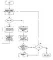
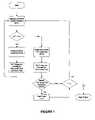
- FIGS. 1 , 1 A and 1 Bare flow diagrams that illustrate control strategies for determining whether to fuel an engine with a main fuel and a secondary fuel or the secondary fuel alone.
- FIG. 1shows a basic control strategy that shows the main operating principle whereas FIGS. 1A and 1B show a more preferred strategies that introduce a deadband to prevent oscillations between the selected operating modes.
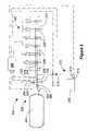
- FIG. 2is a schematic view of a fuel supply system for an engine that can be fuelled with a main gaseous fuel and a secondary liquid fuel.
- FIG. 3is a graph that plots main fuel pressure against time, showing on the left side of the graph how the control strategy works when the main fuel pressure is rising from below a predetermined threshold to a normal operating pressure above the predetermined threshold.
- the right hand side of this graphshows how the control strategy works when the main fuel pressure is declining from above the predetermined threshold to a lower value.
- the present methodis directed to internal combustion engines that are fuelled with a main fuel and a secondary fuel wherein the two fuels can be independently and separately introduced directly into the engine's combustion chamber.
- the secondary fuel injection valveis adapted to introduce smaller quantities of fuel on an energy basis. For such engines, a control strategy is needed to handle the situation when the main fuel is unavailable. This is especially true for engines that have secondary-fuel injection valves with a geometry that restricts secondary fuel mass flow rate to the extent that the engine is unable to operate at full power with secondary fuel alone.
- secondary fuelis a term that is used to describe a second fuel that is normally more auto-ignitable than the main fuel.
- secondary fuelserves as a pilot fuel for assisting with ignition of the main fuel, and, on average can represent less than ten percent of the total fuel consumed on an energy basis.
- the secondary fuelcan be selected from the group consisting of diesel fuel, kerosene, bio-diesel, and dimethylether.
- the secondary fuelis not restricted to describing a fuel that is only employed to act as a pilot for igniting another fuel.
- the described control strategyallows the engine to be fuelled with secondary fuel alone when the main fuel is not available; in such conditions the secondary fuel acts not as a pilot for igniting another fuel, but is itself the only fuel that is consumed by the engine.
- the engine's power outputis reduced and the time that the engine can be operated fuelled with secondary fuel alone can be restricted.
- the main fuelis a gaseous fuel that is cleaner burning than conventional liquid fuels such as diesel.
- the main fuelcan be natural gas, pure methane, butane, propane, hydrogen, and blends thereof.
- the main fuelis a clean-burning gaseous fuel, so in the description of preferred embodiments, “gaseous fuel” is used interchangeably with “main fuel”, but persons familiar with engine technology will understand that the main fuel could also be a liquid fuel that requires a secondary fuel different from the main fuel to trigger ignition.
- gaseous fuelon average, represents at least 90 percent of the fuel consumed on an energy basis, compared to a conventional diesel-fuelled engine, emissions of NOx and particulate matter are much reduced since most of the fuel consumed by the engine is a fuel that is cleaner burning than the liquid fuel that it replaces.
- liquid fuelsare incompressible fluids so as long as there is fuel available, a liquid fuel can be quickly pumped to the desired injection pressure. This is not the case for gaseous fuels.
- gaseous fuelsare compressible and the fluid flow characteristics are different, situations can arise in which the gaseous fuel is not available at the desired injection pressure as quickly, either temporarily, or until the gaseous fuel can be replenished. For example, when the fuel tank that stores the gaseous fuel is empty, gaseous fuel is not available. If one of the components in the fuel system fails or is working at reduced capacity, gaseous fuel may not be available at the desired pressure until appropriate repairs are made and/or maintenance is done to the fuel system.
- gaseous fuelis available, if an accumulator vessel is not employed or if the accumulator is not filled with pressurized gaseous fuel, pressure in the gaseous fuel supply system can be temporarily low until the gaseous fuel pump or compressor is able to charge the system to normal operating pressure.
- the engine controllercan determine from on-board diagnostics that gaseous fuel should not be supplied to the engine, for example if the diagnostics indicate that there may be a leak in the gaseous fuel supply system or that there is a problem with the gaseous fuel injection valves.
- FIG. 1is a flow diagram that shows the basic operating principle of the disclosed control strategy.
- the first stepis to measure the available injection pressure (AIP). This is the pressure of the gaseous fuel inside the main-fuel injection valve, but the actual pressure measurement can be taken in a main-fuel supply pipe or a main-fuel rail that delivers the gaseous fuel to the main-fuel injection valves.
- AIPavailable injection pressure
- Tdthreshold pressure
- the controllerselects the dual fuel operating mode and sets the timing and quantity for the injection of main fuel and secondary fuel into the combustion chamber.
- the threshold pressurecan be about 18 MPA (about 2,600 psi).
- the controllerselects the secondary fuel operating mode and sets the timing and quantity for the injection of secondary fuel only.
- the injection timing and pulse width for the secondary fuelcan change when the controller switches from selecting the secondary fuel operating mode to the dual fuel operating mode, and vice versa, since in the later operating mode the secondary fuel is utilized as a pilot fuel and not as the main fuel.
- the pulse width for injecting the secondary fuelcan be longer and the timing for beginning the injection of the secondary fuel can be earlier in the compression stroke compared to the timing for the beginning of the injection of the main fuel when the dual fuel operating mode is selected.
- the timing for injection of the secondary fuelcan be between 10 and 20 crank angle degrees earlier than the timing for main fuel injection in the dual fuel operating mode.
- the actual timing and pulse widthis dependent upon the characteristics of a given engine.
- a timeris preferably used to limit the time that the engine can operate in this operating mode.
- the secondary fuel operating modeis useful for start up conditions or emergency situations where the main fuel is not available either temporarily or until the supply of gaseous fuel can be replenished or until the main fuel supply system can be serviced.
- the enginecan be started in the secondary fuel operating mode and run in an idle mode until the available injection pressure for the main fuel is increased to the desired operating range.
- the timercan allow the engine to operate for long enough to allow a vehicle to be driven to a safe place to stop, or if full power output is not needed, the vehicle can be driven to a nearby refueling station.
- the timercan be set to allow enough time for a vehicle to driven in the secondary fuel operating mode to a fueling depot in a fleet operator's yard.
- an engine of this typecan not circumvent dual fuel operation for normal vehicle use, and this can make the disclosed engine eligible for clean-fuel subsidies that may not be available to other dual fuel engines that permit the engine to deliver full power when fueled with secondary fuel alone.
- the timer featureis initiated by determining if there was a switch from the dual fuel operating mode to the secondary fuel operating mode.
- predetermined time limit t /can be arbitrarily set because there is already a disincentive to operate in the secondary fuel operating mode since the engine can not achieve full power output in this mode.
- t ⁇can be set to be around 10 minutes, or more preferably an even shorter time.
- FIG. 1Ais a preferred control strategy because it introduces a deadband that reduces oscillations between operating modes.
- the deadbandis a predetermined pressure range that in preferred embodiments can be added or subtracted from the predetermined threshold pressure to define upper and lower pressure limits that are used by the control method in the manner described herein.
- the methodbegins by measuring the available injection pressure (AIP).
- AIPavailable injection pressure
- the first question considered by the controlleris to determine if the available injection pressure is less than the lower pressure limit or greater than the upper pressure limit as defined by the deadband.
- the electronic controllerIf the answer to one of these conditions is “yes” then the available injection pressure is outside of the range defined by the lower and upper pressure limits, and the electronic controller disables the deadband. If the available injection pressure is between the lower and upper pressure limits, and the deadband has been previously enabled, then the deadband remains enabled.
- the second question considered by the electronic controlleris whether the available injection pressure has risen above or dropped below the predetermined threshold pressure since the previous control loop. The disclosed method answers this question by determining if one of two criteria is satisfied. The first criteria is whether the available injection pressure is less than or equal to the predetermined threshold pressure and the available injection pressure measured in the previous control loop was greater than or equal to the predetermined threshold pressure.
- the second criteriais whether the available injection pressure is greater than or equal to the predetermined threshold pressure and the available injection pressure measured in the previous control loop was less than or equal to the predetermined threshold pressure. If one of these criteria is met, this means that the predetermined threshold pressure was equaled or crossed since the previous control loop, and the deadband is enabled. If one of these criteria is not met then no change is made to the status of the deadband before proceeding to the third question, which is whether the available injection pressure is less than the predetermined threshold pressure or whether the deadband is enabled; if one of these is true, then the electronic controller selects the secondary fuel operating mode and sets the fuel injection timing and quantity in accordance with this operating mode. If available injection pressure is not less than the predetermined threshold pressure and the deadband is disabled, then the electronic controller selects the dual fuel operating mode and sets the fuel injection timing and quantity in accordance with this operating mode.
- the deadbandreduces switching back and forth between the dual fuel and secondary fuel operating modes by maintaining the secondary fuel operating mode as long as the deadband is enabled, and by switching to the dual fuel operating mode from the secondary fuel operating mode only when the available injection pressure rises above the upper pressure limit (Td+DB). Once disabled, the deadband is not enabled until the available injection pressure crosses or equals the predetermined threshold pressure.
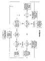
- FIG. 1Billustrates another control method that also uses a deadband with similar results to the control method of FIG. 1A .
- the deadbandis enabled when the available injection pressures equals or crosses the predetermined threshold pressure.
- the electronic controllerswitches from the operating mode selected in the previous control loop to the other operating mode.
- the electronic controllerdisables the deadband and selects the dual fuel operating mode when the measured available injection pressure is greater than the upper pressure limit defined by the predetermined threshold pressure plus the deadband.
- the electronic controllerdisables the deadband and selects the secondary fuel operating mode.
- the first question considered by the electronic controlleris whether the deadband is enabled. If the deadband is enabled, the controller determines if the available injection pressure is still between the upper and lower pressure limits set by the deadbands. If the available injection pressure remains between the upper and lower pressure limits defined by the deadband, then the electronic controller maintains the currently selected operating mode. On the other hand, if the available injection pressure is below the lower pressure limit or above the upper pressure limit, then the electronic controller disables the deadband, while selecting the secondary fuel operating mode if the available injection pressure is less than the lower pressure limit, and otherwise selecting the dual fuel operating mode.
- the electronic controllerdetermines at the first question in the control loop that the deadband is not enabled, the electronic controller considers the measured available injection pressure and the available injection pressure that was measured in the previous control loop to determine if available injection pressure has equaled or crossed the predetermined threshold pressure since the previous control loop. If the available injection pressure has not crossed or equaled the predetermined threshold pressure since the previous control loop, then the deadband remains disabled and if available injection pressure is greater than the predetermined threshold pressure, then the electronic controller selects the dual fuel operating mode, with the secondary fuel operating mode being selected if the available injection pressure is not greater than the predetermined threshold pressure.
- the deadbandis enabled and the electronic controller commands a switch from the operating mode selected in the previous control loop to the other operating mode. If the available injection pressure has crossed or equaled the predetermined threshold pressure since the previous control loop, but the presently measured available injection pressure is not between the lower and upper pressure limits defined by the deadband, then the deadband remains disabled and the electronic controller selects the secondary fuel operating mode if the available injection pressure is less than the lower pressure limit, and otherwise selects the dual fuel operating mode.
- the electronic controllerselects the secondary fuel operating mode when the deadband is enabled, whereas with the control method of FIG. 1B , the electronic controller switches operating modes when the deadband switches from being disabled to enabled. Both control methods impose a deadband to reduce switching back and forth between two operating modes in situations when the available injection pressure fluctuates around a predetermined threshold pressure between upper and lower pressure limits defined by the predetermined deadband.
- FIG. 2is a schematic view of apparatus 200 , which delivers a main fuel and a secondary fuel into a combustion chamber of an internal combustion engine.
- the secondary fuelis a liquid fuel and the main fuel is a gaseous fuel.
- Apparatus 200comprises secondary-fuel supply system 210 , which itself comprises secondary-fuel storage vessel 212 , suction line 213 , secondary-fuel pump 214 , pressure control valve 216 , optional pressure sensor 217 , and secondary-fuel rail 218 .
- Apparatus 200further comprises main-fuel supply system 220 , which itself comprises main-fuel storage vessel 222 , main-fuel compressor 224 , heat exchanger 225 , pressure control valve 226 , pressure sensor 227 , and main-fuel rail 228 .
- the enginecomprises a plurality of fuel injection valves 240 , which are mounted in cylinder head 242 .
- cylinder head 242is schematically shown in dashed outline.
- the enginecan have a cylinder block with six in-line cylinders (not shown), with one fuel injection valve associated with the combustion chamber defined by each cylinder.
- each fuel injection valve 240is capable injecting the secondary fuel and the main fuel into a respective combustion chamber (not shown), so each fuel injection valve 240 is associated with secondary-fuel rail 218 and main-fuel rail 228 .
- the secondary-fuel injection valve and the main-fuel injection valveare integrated into a single dual fuel injection valve
- the secondary-fuel injection valve and the main-fuel injection valveare preferably independently operable to separately introduce the secondary fuel and main fuel into the combustion chambers. This allows separate timing for the secondary fuel and main fuel injection events and more precise control over the quantity of each fuel that is injected into the combustion chambers.
- fuel supply railscan have branches associated with each cylinder head.
- the secondary-fuel injection valvecan be separate from the main-fuel injection valve.
- the main fuel injection valvecan introduce the main fuel into the intake air manifold or the intake ports immediately upstream from the combustion chambers.
- such an embodimentis less preferred since it is preferable to inject the main fuel directly into the combustion chamber to more closely emulate the power, performance and efficiency of a diesel engine, which injects fuel directly into the combustion chamber.
- Fuel injection valves 240are preferably so-called common rail injection valves as shown in FIG. 2 . That is, the fuel is supplied at injection pressure to each one of fuel injection valves 240 through the same fuel rail.
- railas it is defined herein means a conduit, bore, or pipe that functions as a manifold for distributing fuel to the fuel injection valves.
- secondary-fuel rail 218 and main-fuel rail 228are each filled with a pressurized fuel at injection pressure, and fuel can be injected by actuating a respective valve needle from a closed position to an open position.
- the pressure that is measured by pressure sensor 227is representative of the available injection pressure.
- the pressure measured by pressure sensor 217is representative of the available injection pressure for the secondary fuel.
- the disclosed methodis not dependent upon the type of fuel injector that is employed.
- the methodcan be applied to an engine that uses unit injectors, each with an intensifier mechanism for raising the fuel pressure to injection pressure.
- Controller 250is programmable to maintain secondary fuel in secondary-fuel rail 218 at the desired injection pressure by operating pump 214 and by operation of pressure control valve 216 , which is disposed in the secondary-fuel delivery pipe between pump 214 and secondary-fuel rail 218 .
- Pressure control valve 216can be operated to control secondary-fuel pressure in secondary-fuel rail 218 so that it is maintained at a predetermined fixed pressure when the engine is running.
- pressure control valve 216can be controlled by an electronic controller to regulate secondary-fuel pressure within secondary-fuel rail 218 responsive to engine operating conditions, for example to adjust pressure within secondary-fuel rail 218 to predetermined pressures defined by an engine map.
- the secondary-fuel railis shown having a plurality of branches 219 with branches 219 connecting secondary-fuel rail 218 to each one of fuel injection valves 240 .
- Branches 219which are shown schematically in FIG. 2 , can be a bore in cylinder head 242 or if liquid-fuel rail 218 is a pipe, branches 219 can be pipes that connect to fuel injection valves 240 above cylinder head 242 or through an opening provided in cylinder head 242 .
- Controller 250is programmable to maintain main fuel in main-fuel rail 228 at the desired injection pressure by operating compressor 224 and by operation of pressure control valve 226 , which is located in the main-fuel delivery pipe between heat exchanger 225 and main-fuel rail 228 .
- the main fuelis a gaseous fuel that can be stored as a compressed gas at high storage pressures to increase storage density.
- main-fuel storage vessel 222can be a pressure-rated vessel for safely holding the main fuel at pressures up to 69 MPa (about 10,000 psia).
- a gaseous main fuelcan be stored in liquefied form at cryogenic temperatures inside a double-walled vacuum insulated vessel.
- Heat exchanger 225can be employed to cool the main fuel after it has been compressed.
- Main-fuel compressor 224is shown schematically in FIG. 2 , but in a preferred embodiment compressor 224 can be one or a plurality of reciprocating piston compressors.
- Main-fuel supply system 220can further comprise accumulator vessel 230 upstream of pressure regulator 226 . If the volume defined by the main-fuel supply pipe and main-fuel rail 228 is small, accumulator vessel 230 can be employed to facilitate maintaining the desired main-fuel pressure by ensuring that an adequate supply of high-pressure main fuel is available.
- main-fuel rail 228is normally vented or drained.
- Valve 232can be closed when the engine is shut down to reserve some high pressure fuel for when the engine is started up. Upon starting up the engine, valve 232 can be opened to fill main-fuel rail 228 with main fuel.
- the volume of accumulator 230is much greater than the volume of main-fuel rail 228 so that there is normally ample fuel stored at high pressure in accumulator 230 to fill main-fuel rail 228 .
- the volume of accumulator 230is much greater than the volume of main-fuel rail 228 so that there is normally ample fuel stored at high pressure in accumulator 230 to fill main-fuel rail 228 .
- valve 232is opened there may not be sufficient fuel to pressurize the main-fuel rail 228 above a predetermined low pressure set point, which means that compressor 224 is immediately commanded to supply more fuel gas to the fuel supply system.
- valve 232In this situation, if valve 232 is left open, it can take longer to fully pressurize main-fuel rail 228 because compressor 224 is filling main-fuel rail 228 and accumulator 230 at the same time and to further raise the pressure in main-fuel rail 228 compressor 224 would need to also raise the pressure in accumulator vessel 230 .
- valve 232is initially opened to fill main-fuel rail 228 with fuel; meanwhile, pressure regulator 226 is wide open since main fuel pressure is normally initially at atmospheric pressure when the engine is starting up; after a predetermined delay to allow the initial filling of main-fuel rail 228 , valve 232 is closed until the pressure measured by pressure sensor 227 reaches the high set point; and then valve 232 is opened so that compressor 224 can fill accumulator 230 .
- Accumulator 234is an optional feature that can be employed in an engine system that requires accumulator 230 to have a large volume for normal operation but that can use smaller accumulator 234 to speed up initial pressurization of the fuel system by closing valve 232 and using only small accumulator 234 . Once the engine is running in the dual fuel operating mode and the available injection pressure is above the predetermined threshold pressure, valve 232 can be opened and accumulator 230 can be filled.
- main-fuel injection pressureis preferably set to be equal or slightly less than the secondary-fuel injection pressure, so that main fuel, which in preferred embodiments is the gaseous fuel, does not leak into the secondary-fuel passages.
- An apparatus and method of dynamically controlling secondary-fuel and main-fuel pressures in an integrated secondary-fuel and main-fuel injection valveis disclosed in co-owned U.S. Pat. No. 6,298,833. Accordingly, the operation of pressure control valve 226 is preferably linked to the operation of pressure control valve 216 , or one pressure control valve can be employed to maintain a pressure differential between the pressure in secondary-fuel rail 218 and the pressure in main-fuel rail 228 .
- main-fuel rail 228is shown having branches 229 that connect gaseous-fuel rail 228 to respective ones of fuel injection valves 240 .
- Controller 250is an electronic controller that can receive data indicative of engine operating parameters such as engine speed, available injection pressure, and operator inputs such as demanded load. Dashed lines leading from pressure sensors 217 and 227 to controller 250 indicate connections for sending data signals from the pressure sensors to controller 250 . Controller 250 can process the data to determine signal commands by calculation and/or by reference to look up tables. Controller 250 sends signal commands to system components such as pressure control valve 226 or compressor 224 or fuel injection valves 240 as indicated by dashed lines leading from controller 250 to respective components.
- system componentssuch as pressure control valve 226 or compressor 224 or fuel injection valves 240 as indicated by dashed lines leading from controller 250 to respective components.
- controller 250can determine available injection pressure in main-fuel rail 228 , and whether the available injection pressure is sufficient, by being greater than a predetermined threshold pressure, to permit the engine to be operated in a dual fuel mode, or if not, to fuel the engine with only the secondary fuel.
- controller 250is represented schematically as a single component but persons knowledgeable about engine control systems will understand that controller 250 can actually comprise several subcomponents that communicate using a controller area network. For example there can be a primary engine controller with a separate injector driver module, and a separate fuel supply system controller.
- Controller 250can be programmed to follow the methods shown in FIGS. 1 , 1 A and 1 B. For example, as shown by FIGS. 1A and 1B , controller 250 can be programmed to enable a deadband if the available injection pressure equals a predetermined threshold pressure since the last engine cycle or injection event. Controller 250 is also programmable to include a timer for limiting the maximum time that the engine can be run continuously in the secondary fuel operating mode.
- FIG. 3is a plot of available injection pressure (AIP) against time.
- AIPavailable injection pressure
- the main-fuel supply railcan be vented to atmospheric pressure, making it necessary to re-pressurize the main-fuel supply rail upon start up.
- Line 310 on the left hand side of FIG. 3shows an example of how the available injection pressure can increase while the system is being pressurized.
- the controllerselects the secondary fuel operating mode and sends the appropriate signal commands the engine components. For example, the controller sends signal commands to control the secondary fuel injection pressure and to command an appropriate timing and pulse width for each fuel injection event based upon the selected secondary fuel operating mode.
- the available injection pressureequals the predetermined threshold pressure so controller selects and switches to the dual fuel operating mode, and also enables the deadband.
- the controllersends appropriate signal commands to the engine components to operate in the dual fuel mode as long as the available injection pressure remains between the deadband upper limit 316 and the deadband lower limit 326 .
- the available injection pressureequals the deadband upper limit 316 , and when this happens the deadband is disabled and the controller continues to select the dual fuel operating mode since the available injection pressure is greater than the predetermined threshold pressure.
- line 320plots a decline in the available injection pressure.
- the controllerhas initially selected the dual fuel operating mode and the deadband is disabled.
- the deadbandis enabled and the controller selects the secondary fuel operating mode, maintaining this operating mode until line 320 crosses one of the deadband boundaries.
- line 320crosses the deadband lower limit 326 , and at that time the controller disables the deadband and since the available injection pressure is less than the predetermined threshold pressure, the controller continues to select the secondary fuel operating mode.
Landscapes
- Engineering & Computer Science (AREA)
- Chemical & Material Sciences (AREA)
- Combustion & Propulsion (AREA)
- Mechanical Engineering (AREA)
- General Engineering & Computer Science (AREA)
- Oil, Petroleum & Natural Gas (AREA)
- Chemical Kinetics & Catalysis (AREA)
- General Chemical & Material Sciences (AREA)
- Output Control And Ontrol Of Special Type Engine (AREA)
- Electrical Control Of Air Or Fuel Supplied To Internal-Combustion Engine (AREA)
- Fuel-Injection Apparatus (AREA)
Abstract
Description
- (a) a main-fuel supply system comprising a main-fuel injection valve that is operable to introduce the main fuel into a combustion chamber of the engine;
- (b) a secondary-fuel injection system comprising a secondary-fuel injection valve that is operable to introduce the secondary fuel directly into the combustion chamber;
- (c) a pressure sensor associated with the main-fuel supply system for determining an available injection pressure inside the main-fuel injection valve; and
- (d) an electronic controller in communication with the pressure sensor and programmable to separately command actuation of the secondary-fuel injection valve and the main-fuel injection valve when the available injection pressure is greater than a predetermined threshold and to otherwise command actuation of the secondary-fuel injection valve and not the main-fuel injection valve.
- (a) measuring available injection pressure of the main fuel;
- (b) operating in a dual fuel mode by fuelling the engine with the main fuel and the secondary fuel with commanded quantity and injection timing for each fuel determined based upon engine speed and engine load, when the available injection pressure is above a predetermined threshold pressure; and
- (c) operating in a secondary fuel mode by fuelling the engine with secondary fuel alone with commanded quantity and injection timing based upon engine speed and load.
- (d) switching between the dual fuel mode and the secondary fuel mode when the available injection pressure equals the predetermined threshold pressure, and then enabling a deadband which defines a predetermined pressure range that comprises the threshold pressure;
- (e) preventing further switching between operating modes until the deadband is disabled;
- (f) disabling the deadband and operating in the dual fuel mode when the available injection pressure is higher than the predetermined pressure range; and
- (g) disabling the deadband and operating in the secondary fuel mode when the available injection pressure is lower than the predetermined pressure range. In preferred embodiments, the predetermined pressure range has boundaries higher and lower than the threshold pressure.
Claims (24)
Applications Claiming Priority (4)
| Application Number | Priority Date | Filing Date | Title |
|---|---|---|---|
| CA002538980ACA2538980C (en) | 2006-03-10 | 2006-03-10 | Method and apparatus for operating a dual fuel internal combustion engine |
| CAPCT/CA2007/000401 | 2007-03-09 | ||
| CA2,538980 | 2007-03-09 | ||
| PCT/CA2007/000401WO2007104148A1 (en) | 2006-03-10 | 2007-03-09 | Method and apparatus for operating a dual fuel internal combustion engine |
Related Parent Applications (1)
| Application Number | Title | Priority Date | Filing Date |
|---|---|---|---|
| PCT/CA2007/000401ContinuationWO2007104148A1 (en) | 2006-03-10 | 2007-03-09 | Method and apparatus for operating a dual fuel internal combustion engine |
Publications (2)
| Publication Number | Publication Date |
|---|---|
| US20090070008A1 US20090070008A1 (en) | 2009-03-12 |
| US7627416B2true US7627416B2 (en) | 2009-12-01 |
Family
ID=36889431
Family Applications (1)
| Application Number | Title | Priority Date | Filing Date |
|---|---|---|---|
| US12/208,020ActiveUS7627416B2 (en) | 2006-03-10 | 2008-09-10 | Method and apparatus for operating a dual fuel internal combustion engine |
Country Status (5)
| Country | Link |
|---|---|
| US (1) | US7627416B2 (en) |
| CN (1) | CN101415923B (en) |
| AU (1) | AU2007224970B2 (en) |
| CA (1) | CA2538980C (en) |
| WO (1) | WO2007104148A1 (en) |
Cited By (92)
| Publication number | Priority date | Publication date | Assignee | Title |
|---|---|---|---|---|
| US20110017174A1 (en)* | 2009-07-23 | 2011-01-27 | Ford Global Technologies, Llc | Engine with gaseous and/or liquid fuel injector |
| US20110166769A1 (en)* | 2010-01-07 | 2011-07-07 | Jeffrey Douglas Buechler | Supplemental Vapor Fuel Injection System for Internal Combustion Engines |
| US20110208409A1 (en)* | 2008-08-01 | 2011-08-25 | David Benjamin Snyder | Fuel blend sensing system |
| US20110259301A1 (en)* | 2009-01-26 | 2011-10-27 | Kensho Kato | Pressure fluctuation control device for controlling pressure fluctuation in upstream side of common rail |
| US20110288744A1 (en)* | 2008-05-28 | 2011-11-24 | Gokhale Manoj Prakesh | Multi-fuel control system and method |
| US8095294B1 (en)* | 2010-08-19 | 2012-01-10 | Westport Power Inc. | Method for determining fuel injection on-time in a gaseous-fuelled internal combustion engine |
| US20120072095A1 (en)* | 2010-03-10 | 2012-03-22 | Toyota Jidosha Kabushiki Kaisha | Malfunction detecting device for internal combustion engine |
| US20120085326A1 (en)* | 2010-10-10 | 2012-04-12 | Feng Mo | Method and apparatus for converting diesel engines to blended gaseous and diesel fuel engines |
| US20130024094A1 (en)* | 2009-12-31 | 2013-01-24 | Gregory Matthew Shaver | Methods for controlling combustion of blended biofuels |
| WO2013075234A1 (en)* | 2011-11-22 | 2013-05-30 | Westport Power Inc. | Apparatus and method for fuelling a flexible-fuel internal combustion engine |
| US20130306029A1 (en)* | 2012-05-17 | 2013-11-21 | Caterpillar Inc. | Direct Injection Gas Engine and Method |
| US8590515B2 (en) | 2011-06-02 | 2013-11-26 | The Saskatchewan Research Council | Method and system for powering an Otto cycle engine using gasoline and compressed natural gas |
| US8600590B2 (en) | 2012-03-15 | 2013-12-03 | Bright Energy Storage Technologies, Llp | Auxiliary power unit assembly and method of use |
| USD697195S1 (en) | 2012-11-21 | 2014-01-07 | Trilogy Engineered Solutions, LLC | Compressed natural gas manifold |
| US20140074380A1 (en)* | 2012-09-07 | 2014-03-13 | Continental Controls Corporation | Gas substitution control system and method for bi-fuel engine |
| US8683979B2 (en) | 2011-02-14 | 2014-04-01 | Caterpillar Inc. | Dual fuel common rail system and engine using same |
| US8746197B2 (en) | 2012-11-02 | 2014-06-10 | Mcalister Technologies, Llc | Fuel injection systems with enhanced corona burst |
| DE102013021920A1 (en) | 2013-01-02 | 2014-07-03 | Caterpillar Inc. | Dual fuel common rail systems and methods of transitioning from a diesel only to a dual fuel mode of operation |
| US20140182552A1 (en)* | 2013-01-02 | 2014-07-03 | Caterpillar Inc. | Dual fuel common rail system and diesel only method of operating same |
| US8807256B2 (en) | 2012-11-21 | 2014-08-19 | Trilogy Engineered Solutions, LLC | Methods and systems for compressed natural gas (CNG) |
| DE102014001194A1 (en) | 2013-02-27 | 2014-08-28 | Caterpillar Inc. | Apparatus and method for detecting leakage of liquid fuel into a gaseous fuel pressure line |
| DE102014005740A1 (en) | 2013-04-23 | 2014-10-23 | Caterpillar Inc. | DUAL FUEL SYSTEM AND MOTOR SYSTEM OPERATION |
| US8919377B2 (en) | 2011-08-12 | 2014-12-30 | Mcalister Technologies, Llc | Acoustically actuated flow valve assembly including a plurality of reed valves |
| WO2014205566A1 (en)* | 2013-06-28 | 2014-12-31 | Westport Power Inc. | Module for controlling fuel pressure in an internal combustion engine |
| US8944033B2 (en) | 2012-09-07 | 2015-02-03 | Caterpillar Inc. | Limp home capable dual fuel engine and machine using same |
| DE102014012170A1 (en) | 2013-08-19 | 2015-02-19 | Caterpillar Inc. | DUAL FUEL SYSTEM FOR A COMBUSTION ENGINE AND SEAL STRUCTURE FOR LIMITING LEAKAGE |
| US8977473B2 (en) | 2012-08-29 | 2015-03-10 | Caterpillar Inc. | Pressure control strategy for dual fuel compression ignition engine and machine using same |
| US8991423B2 (en) | 2010-05-10 | 2015-03-31 | Go Natural Cng, Llc | Fuel interface modules and related systems and methods |
| US8997725B2 (en) | 2008-01-07 | 2015-04-07 | Mcallister Technologies, Llc | Methods and systems for reducing the formation of oxides of nitrogen during combustion of engines |
| US9014884B2 (en) | 2013-03-15 | 2015-04-21 | Bright Energy Storage Technologies, Llp | Apparatus and method for controlling a locomotive consist |
| US9051909B2 (en) | 2008-01-07 | 2015-06-09 | Mcalister Technologies, Llc | Multifuel storage, metering and ignition system |
| US9169821B2 (en) | 2012-11-02 | 2015-10-27 | Mcalister Technologies, Llc | Fuel injection systems with enhanced corona burst |
| US9169814B2 (en) | 2012-11-02 | 2015-10-27 | Mcalister Technologies, Llc | Systems, methods, and devices with enhanced lorentz thrust |
| US9188069B2 (en) | 2012-12-27 | 2015-11-17 | Caterpillar Inc. | Gaseous fuel system, direct injection gas engine system, and method |
| US20150330325A1 (en)* | 2014-05-13 | 2015-11-19 | GM Global Technology Operations LLC | System and method for controlling a multi-fuel engine to reduce engine pumping losses |
| US9200561B2 (en) | 2012-11-12 | 2015-12-01 | Mcalister Technologies, Llc | Chemical fuel conditioning and activation |
| US20150354473A1 (en)* | 2014-06-09 | 2015-12-10 | Caterpillar Inc | Gas pressure high and low detection |
| US9228536B2 (en) | 2013-12-17 | 2016-01-05 | Cummins Inc. | Load shedding techniques for dual fuel engines |
| US9228506B2 (en) | 2008-05-28 | 2016-01-05 | General Electric Company | Multi-fuel control system and method |
| US9234452B2 (en) | 2012-05-17 | 2016-01-12 | Caterpillar Inc. | Direct injection gas engine and method |
| USD759229S1 (en) | 2013-11-20 | 2016-06-14 | Worthington Industries | Fuel tank frame assembly |
| US9371787B2 (en) | 2008-01-07 | 2016-06-21 | Mcalister Technologies, Llc | Adaptive control system for fuel injectors and igniters |
| DE102016004352A1 (en) | 2015-04-17 | 2016-10-20 | Caterpillar Inc. | DYNAMIC SEAL FOR A NEEDLE REFLECTING ELEMENT OF A FUEL INJECTION DEVICE |
| US9494090B2 (en) | 2013-03-07 | 2016-11-15 | GM Global Technology Operations LLC | System and method for controlling an engine in a bi-fuel vehicle to prevent damage to a catalyst due to engine misfire |
| WO2016187527A1 (en)* | 2015-05-21 | 2016-11-24 | Eco-Fueling, Inc. | Secondary fuel injection system and method for diesel engines |
| US9518518B2 (en) | 2013-04-19 | 2016-12-13 | Caterpillar Inc. | Dual fuel common rail transient pressure control and engine using same |
| US9556805B2 (en) | 2015-02-18 | 2017-01-31 | Caterpillar Inc. | Control system and method for isolating high pressure pilot fuel in dual-fuel HPDI system |
| US9581116B2 (en) | 2008-01-07 | 2017-02-28 | Mcalister Technologies, Llc | Integrated fuel injectors and igniters and associated methods of use and manufacture |
| US9745903B2 (en) | 2015-07-10 | 2017-08-29 | General Electric Company | Dual fuel system for a combustion engine |
| US9752515B1 (en) | 2017-04-03 | 2017-09-05 | James A. Stroup | System, method, and apparatus for injecting a gas in a diesel engine |
| US9938933B2 (en) | 2015-08-28 | 2018-04-10 | General Electric Company | Fuel system for a combustion engine |
| US10439427B2 (en)* | 2017-08-03 | 2019-10-08 | Ford Global Technologies, Llc | Determining a fuel quantity to charge a vehicle battery |
| US10815764B1 (en) | 2019-09-13 | 2020-10-27 | Bj Energy Solutions, Llc | Methods and systems for operating a fleet of pumps |
| US10895202B1 (en) | 2019-09-13 | 2021-01-19 | Bj Energy Solutions, Llc | Direct drive unit removal system and associated methods |
| US10954770B1 (en) | 2020-06-09 | 2021-03-23 | Bj Energy Solutions, Llc | Systems and methods for exchanging fracturing components of a hydraulic fracturing unit |
| US10961908B1 (en) | 2020-06-05 | 2021-03-30 | Bj Energy Solutions, Llc | Systems and methods to enhance intake air flow to a gas turbine engine of a hydraulic fracturing unit |
| US10968837B1 (en) | 2020-05-14 | 2021-04-06 | Bj Energy Solutions, Llc | Systems and methods utilizing turbine compressor discharge for hydrostatic manifold purge |
| US10989180B2 (en) | 2019-09-13 | 2021-04-27 | Bj Energy Solutions, Llc | Power sources and transmission networks for auxiliary equipment onboard hydraulic fracturing units and associated methods |
| US11002189B2 (en) | 2019-09-13 | 2021-05-11 | Bj Energy Solutions, Llc | Mobile gas turbine inlet air conditioning system and associated methods |
| US11015594B2 (en) | 2019-09-13 | 2021-05-25 | Bj Energy Solutions, Llc | Systems and method for use of single mass flywheel alongside torsional vibration damper assembly for single acting reciprocating pump |
| US11015536B2 (en) | 2019-09-13 | 2021-05-25 | Bj Energy Solutions, Llc | Methods and systems for supplying fuel to gas turbine engines |
| US11022526B1 (en) | 2020-06-09 | 2021-06-01 | Bj Energy Solutions, Llc | Systems and methods for monitoring a condition of a fracturing component section of a hydraulic fracturing unit |
| US11028677B1 (en) | 2020-06-22 | 2021-06-08 | Bj Energy Solutions, Llc | Stage profiles for operations of hydraulic systems and associated methods |
| US11066915B1 (en) | 2020-06-09 | 2021-07-20 | Bj Energy Solutions, Llc | Methods for detection and mitigation of well screen out |
| US11098651B1 (en) | 2019-09-13 | 2021-08-24 | Bj Energy Solutions, Llc | Turbine engine exhaust duct system and methods for noise dampening and attenuation |
| US11109508B1 (en) | 2020-06-05 | 2021-08-31 | Bj Energy Solutions, Llc | Enclosure assembly for enhanced cooling of direct drive unit and related methods |
| US11111768B1 (en) | 2020-06-09 | 2021-09-07 | Bj Energy Solutions, Llc | Drive equipment and methods for mobile fracturing transportation platforms |
| US11125066B1 (en) | 2020-06-22 | 2021-09-21 | Bj Energy Solutions, Llc | Systems and methods to operate a dual-shaft gas turbine engine for hydraulic fracturing |
| US11149533B1 (en) | 2020-06-24 | 2021-10-19 | Bj Energy Solutions, Llc | Systems to monitor, detect, and/or intervene relative to cavitation and pulsation events during a hydraulic fracturing operation |
| US11193360B1 (en) | 2020-07-17 | 2021-12-07 | Bj Energy Solutions, Llc | Methods, systems, and devices to enhance fracturing fluid delivery to subsurface formations during high-pressure fracturing operations |
| US11208953B1 (en) | 2020-06-05 | 2021-12-28 | Bj Energy Solutions, Llc | Systems and methods to enhance intake air flow to a gas turbine engine of a hydraulic fracturing unit |
| US11208880B2 (en) | 2020-05-28 | 2021-12-28 | Bj Energy Solutions, Llc | Bi-fuel reciprocating engine to power direct drive turbine fracturing pumps onboard auxiliary systems and related methods |
| US11220895B1 (en) | 2020-06-24 | 2022-01-11 | Bj Energy Solutions, Llc | Automated diagnostics of electronic instrumentation in a system for fracturing a well and associated methods |
| US11236739B2 (en) | 2019-09-13 | 2022-02-01 | Bj Energy Solutions, Llc | Power sources and transmission networks for auxiliary equipment onboard hydraulic fracturing units and associated methods |
| US11268346B2 (en) | 2019-09-13 | 2022-03-08 | Bj Energy Solutions, Llc | Fuel, communications, and power connection systems |
| US11408794B2 (en) | 2019-09-13 | 2022-08-09 | Bj Energy Solutions, Llc | Fuel, communications, and power connection systems and related methods |
| US11415125B2 (en) | 2020-06-23 | 2022-08-16 | Bj Energy Solutions, Llc | Systems for utilization of a hydraulic fracturing unit profile to operate hydraulic fracturing units |
| US11428165B2 (en) | 2020-05-15 | 2022-08-30 | Bj Energy Solutions, Llc | Onboard heater of auxiliary systems using exhaust gases and associated methods |
| US11473413B2 (en) | 2020-06-23 | 2022-10-18 | Bj Energy Solutions, Llc | Systems and methods to autonomously operate hydraulic fracturing units |
| US20230019785A1 (en)* | 2021-07-12 | 2023-01-19 | Liebherr Machines Bulle Sa | Fuel injection device for an internal combustion engine, in particular for a hydrogen combustion engine |
| US11560845B2 (en) | 2019-05-15 | 2023-01-24 | Bj Energy Solutions, Llc | Mobile gas turbine inlet air conditioning system and associated methods |
| US11572843B2 (en) | 2019-09-25 | 2023-02-07 | Clarence Greenlaw | Multiple fuel tank purge system and method |
| US11624326B2 (en) | 2017-05-21 | 2023-04-11 | Bj Energy Solutions, Llc | Methods and systems for supplying fuel to gas turbine engines |
| US11635074B2 (en) | 2020-05-12 | 2023-04-25 | Bj Energy Solutions, Llc | Cover for fluid systems and related methods |
| US11639654B2 (en) | 2021-05-24 | 2023-05-02 | Bj Energy Solutions, Llc | Hydraulic fracturing pumps to enhance flow of fracturing fluid into wellheads and related methods |
| US11867118B2 (en) | 2019-09-13 | 2024-01-09 | Bj Energy Solutions, Llc | Methods and systems for supplying fuel to gas turbine engines |
| US11933153B2 (en) | 2020-06-22 | 2024-03-19 | Bj Energy Solutions, Llc | Systems and methods to operate hydraulic fracturing units using automatic flow rate and/or pressure control |
| US11939853B2 (en) | 2020-06-22 | 2024-03-26 | Bj Energy Solutions, Llc | Systems and methods providing a configurable staged rate increase function to operate hydraulic fracturing units |
| US12065968B2 (en) | 2019-09-13 | 2024-08-20 | BJ Energy Solutions, Inc. | Systems and methods for hydraulic fracturing |
| US12281964B2 (en) | 2019-09-13 | 2025-04-22 | Bj Energy Solutions, Llc | Fuel, communications, and power connection systems and related methods |
| US12338772B2 (en) | 2019-09-13 | 2025-06-24 | Bj Energy Solutions, Llc | Systems, assemblies, and methods to enhance intake air flow to a gas turbine engine of a hydraulic fracturing unit |
| US12378864B2 (en) | 2021-10-25 | 2025-08-05 | Bj Energy Solutions, Llc | Systems and methods to reduce acoustic resonance or disrupt standing wave formation in a fluid manifold of a high-pressure fracturing system |
Families Citing this family (35)
| Publication number | Priority date | Publication date | Assignee | Title |
|---|---|---|---|---|
| US8214129B2 (en)* | 2009-05-13 | 2012-07-03 | Ford Global Technologies, Llc | Distinguishing the fuel admitted to a fuel system |
| CN101603627B (en)* | 2009-07-15 | 2012-07-04 | 中冶南方工程技术有限公司 | Automatic switching and adjustment method for big and small pipes of coal gas mixing station |
| JP5401352B2 (en)* | 2010-02-05 | 2014-01-29 | 株式会社ケーヒン | Fuel switching control device and method |
| US20110174242A1 (en)* | 2010-04-09 | 2011-07-21 | Mcconahay Fred E | Cylindrical hydrogen fuel generator having tubular cells with microscopic indentations |
| US8315788B2 (en)* | 2010-05-19 | 2012-11-20 | Ford Global Technologies, Llc | Method and system for vehicle refueling |
| US8498799B2 (en)* | 2011-05-18 | 2013-07-30 | GM Global Technology Operations LLC | System and method for controlling fuel injection in engines configured to operate using different fuels |
| ITBO20110292A1 (en)* | 2011-05-23 | 2012-11-24 | Magneti Marelli Spa | METHOD OF CHECKING FUEL INJECTION IN A POLI-FUEL INTERNAL COMBUSTION ENGINE IN CASE OF PRESSURE SWITCHES |
| CN102425501A (en)* | 2011-09-28 | 2012-04-25 | 奇瑞汽车股份有限公司 | gasoline/CNG dual-fuel engine |
| CN102383948A (en)* | 2011-09-29 | 2012-03-21 | 曲修青 | Dual-fuel supply system and dual-fuel supply method |
| DE102011088497A1 (en)* | 2011-12-14 | 2013-06-20 | Robert Bosch Gmbh | Method for operating a multi-fuel internal combustion engine by means of two control units and operating according to the inventive method multi-fuel internal combustion engine |
| US20230123561A1 (en)* | 2011-12-16 | 2023-04-20 | Transportation Ip Holdings, Llc | Systems for a multi-fuel capable engine |
| US8903630B2 (en)* | 2012-02-08 | 2014-12-02 | Ford Global Technologies, Llc | Method and system for engine control |
| US8919325B2 (en) | 2012-02-08 | 2014-12-30 | Ford Global Technologies, Llc | Method and system for engine control |
| CA2773651C (en) | 2012-04-05 | 2013-04-09 | Westport Power Inc. | Method and apparatus for controlling fuel pressure in a gaseous fuelled internal combustion engine |
| CN102748143B (en)* | 2012-06-29 | 2015-02-25 | 北京工业大学 | Control method for power system of dimethyl ether/hydrogen internal combustion engine |
| CN102996269A (en)* | 2012-12-07 | 2013-03-27 | 周继光 | Fuel feeding control system of dimethyl ether and natural gas co-firing engine |
| US9212643B2 (en)* | 2013-03-04 | 2015-12-15 | Delia Ltd. | Dual fuel system for an internal combustion engine |
| US9194337B2 (en)* | 2013-03-14 | 2015-11-24 | Advanced Green Innovations, LLC | High pressure direct injected gaseous fuel system and retrofit kit incorporating the same |
| JP6018015B2 (en)* | 2013-05-16 | 2016-11-02 | 愛三工業株式会社 | Vehicle control apparatus and vehicle control method |
| JP2014238071A (en)* | 2013-06-10 | 2014-12-18 | いすゞ自動車株式会社 | Mixed fuel supply system for internal combustion engine, vehicle and mixed fuel supply method for internal combustion engine |
| TR201904733T4 (en)* | 2013-11-22 | 2019-05-21 | Westport Power Inc | Control system for a flexible fuel internal combustion engine. |
| US9410490B2 (en)* | 2014-02-06 | 2016-08-09 | Cummins, Inc. | Fuel selection system and method for dual fuel engines |
| CN103883414B (en)* | 2014-03-21 | 2017-09-01 | 北京工业大学 | Electronic injection device and control method using dimethyl ether and compressed natural gas |
| US9541032B2 (en)* | 2014-05-16 | 2017-01-10 | Adsorbed Natural Gas Products, Inc. | Sorbent-based low pressure gaseous fuel delivery system |
| US9689333B2 (en)* | 2014-07-28 | 2017-06-27 | Cummins Inc. | Dual-fuel engine with enhanced cold start capability |
| US9797317B2 (en)* | 2014-11-10 | 2017-10-24 | Hyundai Motor Company | Method for controlling fuel switching in bi-fuel vehicle |
| DE102015204042A1 (en)* | 2015-03-06 | 2016-09-08 | Robert Bosch Gmbh | Method for controlling the fuel supply from two separate tank systems |
| AT516620B1 (en) | 2015-04-21 | 2016-07-15 | Ge Jenbacher Gmbh & Co Og | Dual fuel engine |
| US10371065B2 (en)* | 2015-06-12 | 2019-08-06 | Westport Power Inc. | High pressure fluid control system and method of controlling pressure bias in an end use device |
| DE102015215490A1 (en)* | 2015-08-13 | 2017-02-16 | Continental Automotive Gmbh | A method of operating a fuel supply device, fuel supply device, and computer program product |
| DE102016201428B4 (en)* | 2016-01-29 | 2017-12-14 | Mtu Friedrichshafen Gmbh | Dual fuel injector, internal combustion engine with such a binary fuel injector, and method of operating such an internal combustion engine |
| US10113696B1 (en) | 2017-06-30 | 2018-10-30 | Adsorbed Natural Gas Products, Inc. | Integrated on-board low-pressure adsorbed natural gas storage system for an adsorbed natural gas vehicle |
| WO2020206224A1 (en) | 2019-04-05 | 2020-10-08 | Kohler Co. | Dual fuel generator |
| JP7213929B1 (en)* | 2021-09-21 | 2023-01-27 | ヤンマーホールディングス株式会社 | Engine system and gaseous fuel combustion method |
| CN115045776B (en)* | 2022-04-28 | 2024-04-30 | 西北工业大学 | A dual-fuel non-isolated pulse detonation engine device and control method thereof |
Citations (8)
| Publication number | Priority date | Publication date | Assignee | Title |
|---|---|---|---|---|
| US4535728A (en) | 1984-02-02 | 1985-08-20 | Propane Carburetion Systems, Inc. | Fuel feed control system and control valve for dual fuel operation of an internal combustion engine |
| US4742801A (en) | 1987-08-13 | 1988-05-10 | Erik Kelgard | Dual fuel mobil engine system |
| US5816224A (en) | 1992-12-22 | 1998-10-06 | Welsh Technologies, Inc. | Method and apparatus for utilizing gaseous and liquid fuels in an internal combustion engine |
| US6101986A (en)* | 1998-03-06 | 2000-08-15 | Caterpillar Inc. | Method for a controlled transition between operating modes of a dual fuel engine |
| US7019626B1 (en)* | 2005-03-03 | 2006-03-28 | Omnitek Engineering, Inc. | Multi-fuel engine conversion system and method |
| US20070199539A1 (en)* | 2006-01-31 | 2007-08-30 | Tim Lennox | Method And Apparatus For Delivering Two Fuels To A Direct Injection Internal Combustion Engine |
| US20080103676A1 (en)* | 2005-05-18 | 2008-05-01 | Richard Ancimer | Direct Injection Gaseous-Fuelled Engine And Method Of Controlling Fuel Injection Pressure |
| US20080262701A1 (en)* | 2007-04-18 | 2008-10-23 | Williams Rodger K | Alternate fuel blending system and associated method |
Family Cites Families (4)
| Publication number | Priority date | Publication date | Assignee | Title |
|---|---|---|---|---|
| US4416244A (en)* | 1981-12-24 | 1983-11-22 | Cummins Engine Company, Inc. | Control system for a dual fuel internal combustion engine |
| US4535782A (en)* | 1984-03-07 | 1985-08-20 | American Cyanamid Company | Method for determining wound volume |
| US6298833B1 (en)* | 2000-04-07 | 2001-10-09 | Westport Research Inc. | Fluid seal apparatus and method for dynamically controlling sealing-fluid pressure |
| AU2003275148A1 (en)* | 2002-09-24 | 2004-04-19 | Engine Control Technology, Llc | Methods and apparatus for operation of multiple fuel engines |
- 2006
- 2006-03-10CACA002538980Apatent/CA2538980C/enactiveActive
- 2007
- 2007-03-09AUAU2007224970Apatent/AU2007224970B2/ennot_activeCeased
- 2007-03-09WOPCT/CA2007/000401patent/WO2007104148A1/enactiveApplication Filing
- 2007-03-09CNCN2007800085968Apatent/CN101415923B/enactiveActive
- 2008
- 2008-09-10USUS12/208,020patent/US7627416B2/enactiveActive
Patent Citations (8)
| Publication number | Priority date | Publication date | Assignee | Title |
|---|---|---|---|---|
| US4535728A (en) | 1984-02-02 | 1985-08-20 | Propane Carburetion Systems, Inc. | Fuel feed control system and control valve for dual fuel operation of an internal combustion engine |
| US4742801A (en) | 1987-08-13 | 1988-05-10 | Erik Kelgard | Dual fuel mobil engine system |
| US5816224A (en) | 1992-12-22 | 1998-10-06 | Welsh Technologies, Inc. | Method and apparatus for utilizing gaseous and liquid fuels in an internal combustion engine |
| US6101986A (en)* | 1998-03-06 | 2000-08-15 | Caterpillar Inc. | Method for a controlled transition between operating modes of a dual fuel engine |
| US7019626B1 (en)* | 2005-03-03 | 2006-03-28 | Omnitek Engineering, Inc. | Multi-fuel engine conversion system and method |
| US20080103676A1 (en)* | 2005-05-18 | 2008-05-01 | Richard Ancimer | Direct Injection Gaseous-Fuelled Engine And Method Of Controlling Fuel Injection Pressure |
| US20070199539A1 (en)* | 2006-01-31 | 2007-08-30 | Tim Lennox | Method And Apparatus For Delivering Two Fuels To A Direct Injection Internal Combustion Engine |
| US20080262701A1 (en)* | 2007-04-18 | 2008-10-23 | Williams Rodger K | Alternate fuel blending system and associated method |
Cited By (241)
| Publication number | Priority date | Publication date | Assignee | Title |
|---|---|---|---|---|
| US9371787B2 (en) | 2008-01-07 | 2016-06-21 | Mcalister Technologies, Llc | Adaptive control system for fuel injectors and igniters |
| US8997725B2 (en) | 2008-01-07 | 2015-04-07 | Mcallister Technologies, Llc | Methods and systems for reducing the formation of oxides of nitrogen during combustion of engines |
| US9051909B2 (en) | 2008-01-07 | 2015-06-09 | Mcalister Technologies, Llc | Multifuel storage, metering and ignition system |
| US9581116B2 (en) | 2008-01-07 | 2017-02-28 | Mcalister Technologies, Llc | Integrated fuel injectors and igniters and associated methods of use and manufacture |
| US20110288744A1 (en)* | 2008-05-28 | 2011-11-24 | Gokhale Manoj Prakesh | Multi-fuel control system and method |
| US8977469B2 (en)* | 2008-05-28 | 2015-03-10 | General Electric Company | Multi-fuel control system and method |
| US9228506B2 (en) | 2008-05-28 | 2016-01-05 | General Electric Company | Multi-fuel control system and method |
| US20110208409A1 (en)* | 2008-08-01 | 2011-08-25 | David Benjamin Snyder | Fuel blend sensing system |
| US20110259301A1 (en)* | 2009-01-26 | 2011-10-27 | Kensho Kato | Pressure fluctuation control device for controlling pressure fluctuation in upstream side of common rail |
| US8813721B2 (en)* | 2009-01-26 | 2014-08-26 | Mitsubishi Heavy Industries, Ltd. | Pressure fluctuation control device for controlling pressure fluctuation in upstream side of common rail |
| US8166956B2 (en)* | 2009-07-23 | 2012-05-01 | Ford Global Technologies, Llc | Engine with gaseous and/or liquid fuel injector |
| US20110017174A1 (en)* | 2009-07-23 | 2011-01-27 | Ford Global Technologies, Llc | Engine with gaseous and/or liquid fuel injector |
| US8342158B2 (en) | 2009-07-23 | 2013-01-01 | Ford Global Technologies, Llc | Engine with gaseous and/or liquid fuel injector |
| US20130024094A1 (en)* | 2009-12-31 | 2013-01-24 | Gregory Matthew Shaver | Methods for controlling combustion of blended biofuels |
| US20110166769A1 (en)* | 2010-01-07 | 2011-07-07 | Jeffrey Douglas Buechler | Supplemental Vapor Fuel Injection System for Internal Combustion Engines |
| US8918268B2 (en)* | 2010-03-10 | 2014-12-23 | Toyota Jidosha Kabushiki Kaisha | Malfunction detecting device for internal combustion engine |
| US20120072095A1 (en)* | 2010-03-10 | 2012-03-22 | Toyota Jidosha Kabushiki Kaisha | Malfunction detecting device for internal combustion engine |
| US9353712B2 (en) | 2010-05-10 | 2016-05-31 | Go Natural Cng, Llc | Fuel interface modules and related systems and methods |
| US8991423B2 (en) | 2010-05-10 | 2015-03-31 | Go Natural Cng, Llc | Fuel interface modules and related systems and methods |
| US8095294B1 (en)* | 2010-08-19 | 2012-01-10 | Westport Power Inc. | Method for determining fuel injection on-time in a gaseous-fuelled internal combustion engine |
| US20120085326A1 (en)* | 2010-10-10 | 2012-04-12 | Feng Mo | Method and apparatus for converting diesel engines to blended gaseous and diesel fuel engines |
| US8683979B2 (en) | 2011-02-14 | 2014-04-01 | Caterpillar Inc. | Dual fuel common rail system and engine using same |
| US8590515B2 (en) | 2011-06-02 | 2013-11-26 | The Saskatchewan Research Council | Method and system for powering an Otto cycle engine using gasoline and compressed natural gas |
| US8919377B2 (en) | 2011-08-12 | 2014-12-30 | Mcalister Technologies, Llc | Acoustically actuated flow valve assembly including a plurality of reed valves |
| WO2013075234A1 (en)* | 2011-11-22 | 2013-05-30 | Westport Power Inc. | Apparatus and method for fuelling a flexible-fuel internal combustion engine |
| US9856837B2 (en) | 2011-11-22 | 2018-01-02 | Westport Power Inc. | Apparatus and method for fuelling a flexible-fuel internal combustion engine |
| US8600590B2 (en) | 2012-03-15 | 2013-12-03 | Bright Energy Storage Technologies, Llp | Auxiliary power unit assembly and method of use |
| US8880248B2 (en) | 2012-03-15 | 2014-11-04 | Bright Energy Storage Technologies, Llp | Auxiliary power unit assembly and method of use |
| US8855839B2 (en) | 2012-03-15 | 2014-10-07 | Bright Energy Storage Technologies, Llp | Fuel tank assembly and method of use |
| US9321467B2 (en) | 2012-03-15 | 2016-04-26 | Bright Energy Storage Technologies, Llp | Fuel tank assembly and method of use |
| US9821819B2 (en) | 2012-03-15 | 2017-11-21 | Bright Energy Storage Technologies, Llp | Auxiliary power unit assembly and method of use |
| US9145149B2 (en) | 2012-03-15 | 2015-09-29 | Bright Energy Storage Technologies, Llp | Auxiliary power unit assembly and method of use |
| US9114812B2 (en) | 2012-03-15 | 2015-08-25 | Bright Energy Storage Technologies, Llp | Apparatus and method for controlling a locomotive consist having a locomotive and auxiliary power unit |
| US9234452B2 (en) | 2012-05-17 | 2016-01-12 | Caterpillar Inc. | Direct injection gas engine and method |
| US20130306029A1 (en)* | 2012-05-17 | 2013-11-21 | Caterpillar Inc. | Direct Injection Gas Engine and Method |
| US8977473B2 (en) | 2012-08-29 | 2015-03-10 | Caterpillar Inc. | Pressure control strategy for dual fuel compression ignition engine and machine using same |
| US20140074380A1 (en)* | 2012-09-07 | 2014-03-13 | Continental Controls Corporation | Gas substitution control system and method for bi-fuel engine |
| US8944033B2 (en) | 2012-09-07 | 2015-02-03 | Caterpillar Inc. | Limp home capable dual fuel engine and machine using same |
| US9169821B2 (en) | 2012-11-02 | 2015-10-27 | Mcalister Technologies, Llc | Fuel injection systems with enhanced corona burst |
| US8746197B2 (en) | 2012-11-02 | 2014-06-10 | Mcalister Technologies, Llc | Fuel injection systems with enhanced corona burst |
| US9631592B2 (en) | 2012-11-02 | 2017-04-25 | Mcalister Technologies, Llc | Fuel injection systems with enhanced corona burst |
| US9169814B2 (en) | 2012-11-02 | 2015-10-27 | Mcalister Technologies, Llc | Systems, methods, and devices with enhanced lorentz thrust |
| US8752524B2 (en) | 2012-11-02 | 2014-06-17 | Mcalister Technologies, Llc | Fuel injection systems with enhanced thrust |
| US9200561B2 (en) | 2012-11-12 | 2015-12-01 | Mcalister Technologies, Llc | Chemical fuel conditioning and activation |
| US9855841B2 (en) | 2012-11-21 | 2018-01-02 | Worthington Industries, Inc. | Methods and systems for compressed natural gas (CNG) |
| US10906395B2 (en) | 2012-11-21 | 2021-02-02 | Worthington Industries Inc. | Methods and systems for compressed natural gas (CNG) |
| US9086187B2 (en) | 2012-11-21 | 2015-07-21 | Trilogy Engineered Solutions, LLC | Methods and systems for compressed natural gas (CNG) |
| US8807256B2 (en) | 2012-11-21 | 2014-08-19 | Trilogy Engineered Solutions, LLC | Methods and systems for compressed natural gas (CNG) |
| USD697195S1 (en) | 2012-11-21 | 2014-01-07 | Trilogy Engineered Solutions, LLC | Compressed natural gas manifold |
| US8915322B2 (en) | 2012-11-21 | 2014-12-23 | Trilogy Engineered Solutions, LLC | Methods and systems for compressed natural gas (CNG) system |
| US9358877B2 (en) | 2012-11-21 | 2016-06-07 | Worthington Industries | Methods and systems for compressed natural gas (CNG) |
| US9188069B2 (en) | 2012-12-27 | 2015-11-17 | Caterpillar Inc. | Gaseous fuel system, direct injection gas engine system, and method |
| US20140182552A1 (en)* | 2013-01-02 | 2014-07-03 | Caterpillar Inc. | Dual fuel common rail system and diesel only method of operating same |
| US9228507B2 (en)* | 2013-01-02 | 2016-01-05 | Caterpillar Inc. | Dual fuel common rail system and diesel only method of operating same |
| DE102013021920A1 (en) | 2013-01-02 | 2014-07-03 | Caterpillar Inc. | Dual fuel common rail systems and methods of transitioning from a diesel only to a dual fuel mode of operation |
| DE102013021920B4 (en) | 2013-01-02 | 2025-03-20 | Caterpillar Inc. | Dual-fuel common rail systems and methods for transitioning from a diesel-only to a dual-fuel operating mode |
| DE102013021921B4 (en)* | 2013-01-02 | 2025-08-07 | Caterpillar Inc. | Dual-fuel common rail system and operating procedures therefor in diesel mode |
| DE102013021921A1 (en) | 2013-01-02 | 2014-07-03 | Caterpillar Inc. | Dual fuel common rail system and operating method for diesel mode |
| US8909457B2 (en) | 2013-01-02 | 2014-12-09 | Caterpillar Inc. | Dual fuel common rail system and method of transitioning from diesel only to dual fuel method of operation |
| DE102014001194A1 (en) | 2013-02-27 | 2014-08-28 | Caterpillar Inc. | Apparatus and method for detecting leakage of liquid fuel into a gaseous fuel pressure line |
| US9494090B2 (en) | 2013-03-07 | 2016-11-15 | GM Global Technology Operations LLC | System and method for controlling an engine in a bi-fuel vehicle to prevent damage to a catalyst due to engine misfire |
| US9403539B2 (en) | 2013-03-15 | 2016-08-02 | Bright Energy Storage Technologies, Llp | Apparatus and method for controlling a locomotive consist |
| US9630633B2 (en) | 2013-03-15 | 2017-04-25 | Bright Energy Storage Technologies, Llp | Apparatus and method for controlling a locomotive consist |
| US9014884B2 (en) | 2013-03-15 | 2015-04-21 | Bright Energy Storage Technologies, Llp | Apparatus and method for controlling a locomotive consist |
| US9518518B2 (en) | 2013-04-19 | 2016-12-13 | Caterpillar Inc. | Dual fuel common rail transient pressure control and engine using same |
| DE102014005740A1 (en) | 2013-04-23 | 2014-10-23 | Caterpillar Inc. | DUAL FUEL SYSTEM AND MOTOR SYSTEM OPERATION |
| WO2014205566A1 (en)* | 2013-06-28 | 2014-12-31 | Westport Power Inc. | Module for controlling fuel pressure in an internal combustion engine |
| US20160146147A1 (en)* | 2013-06-28 | 2016-05-26 | Westport Power Inc. | Module for controlling fuel pressure in an internal combustion engine |
| DE102014012170A1 (en) | 2013-08-19 | 2015-02-19 | Caterpillar Inc. | DUAL FUEL SYSTEM FOR A COMBUSTION ENGINE AND SEAL STRUCTURE FOR LIMITING LEAKAGE |
| USD759229S1 (en) | 2013-11-20 | 2016-06-14 | Worthington Industries | Fuel tank frame assembly |
| US9228536B2 (en) | 2013-12-17 | 2016-01-05 | Cummins Inc. | Load shedding techniques for dual fuel engines |
| US9457789B2 (en)* | 2014-05-13 | 2016-10-04 | GM Global Technology Operations LLC | System and method for controlling a multi-fuel engine to reduce engine pumping losses |
| US20150330325A1 (en)* | 2014-05-13 | 2015-11-19 | GM Global Technology Operations LLC | System and method for controlling a multi-fuel engine to reduce engine pumping losses |
| US9657653B2 (en)* | 2014-06-09 | 2017-05-23 | Caterpillar Inc. | Gas pressure high and low detection |
| US20150354473A1 (en)* | 2014-06-09 | 2015-12-10 | Caterpillar Inc | Gas pressure high and low detection |
| US9556805B2 (en) | 2015-02-18 | 2017-01-31 | Caterpillar Inc. | Control system and method for isolating high pressure pilot fuel in dual-fuel HPDI system |
| DE102016004352A1 (en) | 2015-04-17 | 2016-10-20 | Caterpillar Inc. | DYNAMIC SEAL FOR A NEEDLE REFLECTING ELEMENT OF A FUEL INJECTION DEVICE |
| WO2016187527A1 (en)* | 2015-05-21 | 2016-11-24 | Eco-Fueling, Inc. | Secondary fuel injection system and method for diesel engines |
| US9745903B2 (en) | 2015-07-10 | 2017-08-29 | General Electric Company | Dual fuel system for a combustion engine |
| US9938933B2 (en) | 2015-08-28 | 2018-04-10 | General Electric Company | Fuel system for a combustion engine |
| US10161318B2 (en) | 2017-04-03 | 2018-12-25 | James A. Stroup | System, method, and apparatus for injecting a gas in a diesel engine |
| US9752515B1 (en) | 2017-04-03 | 2017-09-05 | James A. Stroup | System, method, and apparatus for injecting a gas in a diesel engine |
| US11624326B2 (en) | 2017-05-21 | 2023-04-11 | Bj Energy Solutions, Llc | Methods and systems for supplying fuel to gas turbine engines |
| US10439427B2 (en)* | 2017-08-03 | 2019-10-08 | Ford Global Technologies, Llc | Determining a fuel quantity to charge a vehicle battery |
| US11560845B2 (en) | 2019-05-15 | 2023-01-24 | Bj Energy Solutions, Llc | Mobile gas turbine inlet air conditioning system and associated methods |
| US11629584B2 (en) | 2019-09-13 | 2023-04-18 | Bj Energy Solutions, Llc | Power sources and transmission networks for auxiliary equipment onboard hydraulic fracturing units and associated methods |
| US11761846B2 (en) | 2019-09-13 | 2023-09-19 | Bj Energy Solutions, Llc | Fuel, communications, and power connection systems and related methods |
| US11598263B2 (en) | 2019-09-13 | 2023-03-07 | Bj Energy Solutions, Llc | Mobile gas turbine inlet air conditioning system and associated methods |
| US10982596B1 (en) | 2019-09-13 | 2021-04-20 | Bj Energy Solutions, Llc | Direct drive unit removal system and associated methods |
| US10989180B2 (en) | 2019-09-13 | 2021-04-27 | Bj Energy Solutions, Llc | Power sources and transmission networks for auxiliary equipment onboard hydraulic fracturing units and associated methods |
| US11002189B2 (en) | 2019-09-13 | 2021-05-11 | Bj Energy Solutions, Llc | Mobile gas turbine inlet air conditioning system and associated methods |
| US11604113B2 (en) | 2019-09-13 | 2023-03-14 | Bj Energy Solutions, Llc | Fuel, communications, and power connection systems and related methods |
| US11015594B2 (en) | 2019-09-13 | 2021-05-25 | Bj Energy Solutions, Llc | Systems and method for use of single mass flywheel alongside torsional vibration damper assembly for single acting reciprocating pump |
| US11015536B2 (en) | 2019-09-13 | 2021-05-25 | Bj Energy Solutions, Llc | Methods and systems for supplying fuel to gas turbine engines |
| US11578660B1 (en) | 2019-09-13 | 2023-02-14 | Bj Energy Solutions, Llc | Direct drive unit removal system and associated methods |
| US10815764B1 (en) | 2019-09-13 | 2020-10-27 | Bj Energy Solutions, Llc | Methods and systems for operating a fleet of pumps |
| US11060455B1 (en) | 2019-09-13 | 2021-07-13 | Bj Energy Solutions, Llc | Mobile gas turbine inlet air conditioning system and associated methods |
| US12338772B2 (en) | 2019-09-13 | 2025-06-24 | Bj Energy Solutions, Llc | Systems, assemblies, and methods to enhance intake air flow to a gas turbine engine of a hydraulic fracturing unit |
| US12281964B2 (en) | 2019-09-13 | 2025-04-22 | Bj Energy Solutions, Llc | Fuel, communications, and power connection systems and related methods |
| US11092152B2 (en) | 2019-09-13 | 2021-08-17 | Bj Energy Solutions, Llc | Systems and method for use of single mass flywheel alongside torsional vibration damper assembly for single acting reciprocating pump |
| US11098651B1 (en) | 2019-09-13 | 2021-08-24 | Bj Energy Solutions, Llc | Turbine engine exhaust duct system and methods for noise dampening and attenuation |
| US11608725B2 (en) | 2019-09-13 | 2023-03-21 | Bj Energy Solutions, Llc | Methods and systems for operating a fleet of pumps |
| US12276577B2 (en) | 2019-09-13 | 2025-04-15 | Bj Energy Solutions, Llc | Fuel, communications, and power connection systems and related methods |
| US10895202B1 (en) | 2019-09-13 | 2021-01-19 | Bj Energy Solutions, Llc | Direct drive unit removal system and associated methods |
| US10961912B1 (en) | 2019-09-13 | 2021-03-30 | Bj Energy Solutions, Llc | Direct drive unit removal system and associated methods |
| US11149726B1 (en) | 2019-09-13 | 2021-10-19 | Bj Energy Solutions, Llc | Systems and method for use of single mass flywheel alongside torsional vibration damper assembly for single acting reciprocating pump |
| US12092100B2 (en) | 2019-09-13 | 2024-09-17 | Bj Energy Solutions, Llc | Systems and method for use of single mass flywheel alongside torsional vibration damper assembly for single acting reciprocating pump |
| US11156159B1 (en) | 2019-09-13 | 2021-10-26 | Bj Energy Solutions, Llc | Mobile gas turbine inlet air conditioning system and associated methods |
| US12065968B2 (en) | 2019-09-13 | 2024-08-20 | BJ Energy Solutions, Inc. | Systems and methods for hydraulic fracturing |
| US12049808B2 (en) | 2019-09-13 | 2024-07-30 | Bj Energy Solutions, Llc | Methods and systems for operating a fleet of pumps |
| US11971028B2 (en) | 2019-09-13 | 2024-04-30 | Bj Energy Solutions, Llc | Systems and method for use of single mass flywheel alongside torsional vibration damper assembly for single acting reciprocating pump |
| US11560848B2 (en) | 2019-09-13 | 2023-01-24 | Bj Energy Solutions, Llc | Methods for noise dampening and attenuation of turbine engine |
| US11613980B2 (en) | 2019-09-13 | 2023-03-28 | Bj Energy Solutions, Llc | Methods and systems for operating a fleet of pumps |
| US11555756B2 (en) | 2019-09-13 | 2023-01-17 | Bj Energy Solutions, Llc | Fuel, communications, and power connection systems and related methods |
| US11619122B2 (en) | 2019-09-13 | 2023-04-04 | Bj Energy Solutions, Llc | Methods and systems for operating a fleet of pumps |
| US11530602B2 (en) | 2019-09-13 | 2022-12-20 | Bj Energy Solutions, Llc | Power sources and transmission networks for auxiliary equipment onboard hydraulic fracturing units and associated methods |
| US11867118B2 (en) | 2019-09-13 | 2024-01-09 | Bj Energy Solutions, Llc | Methods and systems for supplying fuel to gas turbine engines |
| US11236739B2 (en) | 2019-09-13 | 2022-02-01 | Bj Energy Solutions, Llc | Power sources and transmission networks for auxiliary equipment onboard hydraulic fracturing units and associated methods |
| US11859482B2 (en) | 2019-09-13 | 2024-01-02 | Bj Energy Solutions, Llc | Power sources and transmission networks for auxiliary equipment onboard hydraulic fracturing units and associated methods |
| US11852001B2 (en) | 2019-09-13 | 2023-12-26 | Bj Energy Solutions, Llc | Methods and systems for operating a fleet of pumps |
| US11512642B1 (en) | 2019-09-13 | 2022-11-29 | Bj Energy Solutions, Llc | Direct drive unit removal system and associated methods |
| US11268346B2 (en) | 2019-09-13 | 2022-03-08 | Bj Energy Solutions, Llc | Fuel, communications, and power connection systems |
| US11767791B2 (en) | 2019-09-13 | 2023-09-26 | Bj Energy Solutions, Llc | Mobile gas turbine inlet air conditioning system and associated methods |
| US11280266B2 (en) | 2019-09-13 | 2022-03-22 | Bj Energy Solutions, Llc | Mobile gas turbine inlet air conditioning system and associated methods |
| US11280331B2 (en) | 2019-09-13 | 2022-03-22 | Bj Energy Solutions, Llc | Systems and method for use of single mass flywheel alongside torsional vibration damper assembly for single acting reciprocating pump |
| US11287350B2 (en) | 2019-09-13 | 2022-03-29 | Bj Energy Solutions, Llc | Fuel, communications, and power connection methods |
| US10907459B1 (en) | 2019-09-13 | 2021-02-02 | Bj Energy Solutions, Llc | Methods and systems for operating a fleet of pumps |
| US11473997B2 (en) | 2019-09-13 | 2022-10-18 | Bj Energy Solutions, Llc | Fuel, communications, and power connection systems and related methods |
| US11473503B1 (en) | 2019-09-13 | 2022-10-18 | Bj Energy Solutions, Llc | Direct drive unit removal system and associated methods |
| US11649766B1 (en) | 2019-09-13 | 2023-05-16 | Bj Energy Solutions, Llc | Mobile gas turbine inlet air conditioning system and associated methods |
| US11319878B2 (en) | 2019-09-13 | 2022-05-03 | Bj Energy Solutions, Llc | Direct drive unit removal system and associated methods |
| US11725583B2 (en) | 2019-09-13 | 2023-08-15 | Bj Energy Solutions, Llc | Mobile gas turbine inlet air conditioning system and associated methods |
| US11346280B1 (en) | 2019-09-13 | 2022-05-31 | Bj Energy Solutions, Llc | Direct drive unit removal system and associated methods |
| US11719234B2 (en) | 2019-09-13 | 2023-08-08 | Bj Energy Solutions, Llc | Systems and method for use of single mass flywheel alongside torsional vibration damper assembly for single acting reciprocating pump |
| US11459954B2 (en) | 2019-09-13 | 2022-10-04 | Bj Energy Solutions, Llc | Turbine engine exhaust duct system and methods for noise dampening and attenuation |
| US11460368B2 (en) | 2019-09-13 | 2022-10-04 | Bj Energy Solutions, Llc | Fuel, communications, and power connection systems and related methods |
| US11655763B1 (en) | 2019-09-13 | 2023-05-23 | Bj Energy Solutions, Llc | Direct drive unit removal system and associated methods |
| US11401865B1 (en) | 2019-09-13 | 2022-08-02 | Bj Energy Solutions, Llc | Direct drive unit removal system and associated methods |
| US11415056B1 (en) | 2019-09-13 | 2022-08-16 | Bj Energy Solutions, Llc | Turbine engine exhaust duct system and methods for noise dampening and attenuation |
| US11408794B2 (en) | 2019-09-13 | 2022-08-09 | Bj Energy Solutions, Llc | Fuel, communications, and power connection systems and related methods |
| US11572843B2 (en) | 2019-09-25 | 2023-02-07 | Clarence Greenlaw | Multiple fuel tank purge system and method |
| US11635074B2 (en) | 2020-05-12 | 2023-04-25 | Bj Energy Solutions, Llc | Cover for fluid systems and related methods |
| US11708829B2 (en) | 2020-05-12 | 2023-07-25 | Bj Energy Solutions, Llc | Cover for fluid systems and related methods |
| US12404856B2 (en) | 2020-05-12 | 2025-09-02 | Bj Energy Solutions, Llc | Cover for fluid systems and related methods |
| US10968837B1 (en) | 2020-05-14 | 2021-04-06 | Bj Energy Solutions, Llc | Systems and methods utilizing turbine compressor discharge for hydrostatic manifold purge |
| US11898504B2 (en) | 2020-05-14 | 2024-02-13 | Bj Energy Solutions, Llc | Systems and methods utilizing turbine compressor discharge for hydrostatic manifold purge |
| US11434820B2 (en) | 2020-05-15 | 2022-09-06 | Bj Energy Solutions, Llc | Onboard heater of auxiliary systems using exhaust gases and associated methods |
| US11428165B2 (en) | 2020-05-15 | 2022-08-30 | Bj Energy Solutions, Llc | Onboard heater of auxiliary systems using exhaust gases and associated methods |
| US11624321B2 (en) | 2020-05-15 | 2023-04-11 | Bj Energy Solutions, Llc | Onboard heater of auxiliary systems using exhaust gases and associated methods |
| US11698028B2 (en) | 2020-05-15 | 2023-07-11 | Bj Energy Solutions, Llc | Onboard heater of auxiliary systems using exhaust gases and associated methods |
| US11959419B2 (en) | 2020-05-15 | 2024-04-16 | Bj Energy Solutions, Llc | Onboard heater of auxiliary systems using exhaust gases and associated methods |
| US11542868B2 (en) | 2020-05-15 | 2023-01-03 | Bj Energy Solutions, Llc | Onboard heater of auxiliary systems using exhaust gases and associated methods |
| US11603745B2 (en) | 2020-05-28 | 2023-03-14 | Bj Energy Solutions, Llc | Bi-fuel reciprocating engine to power direct drive turbine fracturing pumps onboard auxiliary systems and related methods |
| US11365616B1 (en) | 2020-05-28 | 2022-06-21 | Bj Energy Solutions, Llc | Bi-fuel reciprocating engine to power direct drive turbine fracturing pumps onboard auxiliary systems and related methods |
| US11313213B2 (en) | 2020-05-28 | 2022-04-26 | Bj Energy Solutions, Llc | Bi-fuel reciprocating engine to power direct drive turbine fracturing pumps onboard auxiliary systems and related methods |
| US11208880B2 (en) | 2020-05-28 | 2021-12-28 | Bj Energy Solutions, Llc | Bi-fuel reciprocating engine to power direct drive turbine fracturing pumps onboard auxiliary systems and related methods |
| US11814940B2 (en) | 2020-05-28 | 2023-11-14 | Bj Energy Solutions Llc | Bi-fuel reciprocating engine to power direct drive turbine fracturing pumps onboard auxiliary systems and related methods |
| US11627683B2 (en) | 2020-06-05 | 2023-04-11 | Bj Energy Solutions, Llc | Enclosure assembly for enhanced cooling of direct drive unit and related methods |
| US11891952B2 (en) | 2020-06-05 | 2024-02-06 | Bj Energy Solutions, Llc | Systems and methods to enhance intake air flow to a gas turbine engine of a hydraulic fracturing unit |
| US11598264B2 (en) | 2020-06-05 | 2023-03-07 | Bj Energy Solutions, Llc | Systems and methods to enhance intake air flow to a gas turbine engine of a hydraulic fracturing unit |
| US11208953B1 (en) | 2020-06-05 | 2021-12-28 | Bj Energy Solutions, Llc | Systems and methods to enhance intake air flow to a gas turbine engine of a hydraulic fracturing unit |
| US11129295B1 (en) | 2020-06-05 | 2021-09-21 | Bj Energy Solutions, Llc | Enclosure assembly for enhanced cooling of direct drive unit and related methods |
| US11109508B1 (en) | 2020-06-05 | 2021-08-31 | Bj Energy Solutions, Llc | Enclosure assembly for enhanced cooling of direct drive unit and related methods |
| US10961908B1 (en) | 2020-06-05 | 2021-03-30 | Bj Energy Solutions, Llc | Systems and methods to enhance intake air flow to a gas turbine engine of a hydraulic fracturing unit |
| US11300050B2 (en) | 2020-06-05 | 2022-04-12 | Bj Energy Solutions, Llc | Systems and methods to enhance intake air flow to a gas turbine engine of a hydraulic fracturing unit |
| US11746698B2 (en) | 2020-06-05 | 2023-09-05 | Bj Energy Solutions, Llc | Systems and methods to enhance intake air flow to a gas turbine engine of a hydraulic fracturing unit |
| US11378008B2 (en) | 2020-06-05 | 2022-07-05 | Bj Energy Solutions, Llc | Systems and methods to enhance intake air flow to a gas turbine engine of a hydraulic fracturing unit |
| US12408291B2 (en) | 2020-06-05 | 2025-09-02 | Bj Energy Solutions, Llc | Enclosure assembly for enhanced cooling of direct drive unit and related methods |
| US11723171B2 (en) | 2020-06-05 | 2023-08-08 | Bj Energy Solutions, Llc | Enclosure assembly for enhanced cooling of direct drive unit and related methods |
| US11566506B2 (en) | 2020-06-09 | 2023-01-31 | Bj Energy Solutions, Llc | Methods for detection and mitigation of well screen out |
| US12305495B2 (en) | 2020-06-09 | 2025-05-20 | Bj Energy Solutions, Llc | Systems and methods for exchanging fracturing components of a hydraulic fracturing unit |
| US11867046B2 (en) | 2020-06-09 | 2024-01-09 | Bj Energy Solutions, Llc | Systems and methods for exchanging fracturing components of a hydraulic fracturing unit |
| US11939854B2 (en) | 2020-06-09 | 2024-03-26 | Bj Energy Solutions, Llc | Methods for detection and mitigation of well screen out |
| US11015423B1 (en) | 2020-06-09 | 2021-05-25 | Bj Energy Solutions, Llc | Systems and methods for exchanging fracturing components of a hydraulic fracturing unit |
| US11261717B2 (en) | 2020-06-09 | 2022-03-01 | Bj Energy Solutions, Llc | Systems and methods for exchanging fracturing components of a hydraulic fracturing unit |
| US11022526B1 (en) | 2020-06-09 | 2021-06-01 | Bj Energy Solutions, Llc | Systems and methods for monitoring a condition of a fracturing component section of a hydraulic fracturing unit |
| US12385379B2 (en) | 2020-06-09 | 2025-08-12 | Bj Energy Solutions, Llc | Methods for detection and mitigation of well screen out |
| US11512570B2 (en) | 2020-06-09 | 2022-11-29 | Bj Energy Solutions, Llc | Systems and methods for exchanging fracturing components of a hydraulic fracturing unit |
| US11174716B1 (en) | 2020-06-09 | 2021-11-16 | Bj Energy Solutions, Llc | Drive equipment and methods for mobile fracturing transportation platforms |
| US10954770B1 (en) | 2020-06-09 | 2021-03-23 | Bj Energy Solutions, Llc | Systems and methods for exchanging fracturing components of a hydraulic fracturing unit |
| US11066915B1 (en) | 2020-06-09 | 2021-07-20 | Bj Energy Solutions, Llc | Methods for detection and mitigation of well screen out |
| US11629583B2 (en) | 2020-06-09 | 2023-04-18 | Bj Energy Solutions, Llc | Systems and methods for exchanging fracturing components of a hydraulic fracturing unit |
| US11319791B2 (en) | 2020-06-09 | 2022-05-03 | Bj Energy Solutions, Llc | Methods and systems for detection and mitigation of well screen out |
| US11339638B1 (en) | 2020-06-09 | 2022-05-24 | Bj Energy Solutions, Llc | Systems and methods for exchanging fracturing components of a hydraulic fracturing unit |
| US11111768B1 (en) | 2020-06-09 | 2021-09-07 | Bj Energy Solutions, Llc | Drive equipment and methods for mobile fracturing transportation platforms |
| US11643915B2 (en) | 2020-06-09 | 2023-05-09 | Bj Energy Solutions, Llc | Drive equipment and methods for mobile fracturing transportation platforms |
| US11085281B1 (en) | 2020-06-09 | 2021-08-10 | Bj Energy Solutions, Llc | Systems and methods for exchanging fracturing components of a hydraulic fracturing unit |
| US11208881B1 (en) | 2020-06-09 | 2021-12-28 | Bj Energy Solutions, Llc | Methods and systems for detection and mitigation of well screen out |
| US11236598B1 (en) | 2020-06-22 | 2022-02-01 | Bj Energy Solutions, Llc | Stage profiles for operations of hydraulic systems and associated methods |
| US11125066B1 (en) | 2020-06-22 | 2021-09-21 | Bj Energy Solutions, Llc | Systems and methods to operate a dual-shaft gas turbine engine for hydraulic fracturing |
| US11933153B2 (en) | 2020-06-22 | 2024-03-19 | Bj Energy Solutions, Llc | Systems and methods to operate hydraulic fracturing units using automatic flow rate and/or pressure control |
| US12286874B2 (en) | 2020-06-22 | 2025-04-29 | Bj Energy Solutions, Llc | Systems and methods to operate hydraulic fracturing units using automatic flow rate and/or pressure control |
| US11598188B2 (en) | 2020-06-22 | 2023-03-07 | Bj Energy Solutions, Llc | Stage profiles for operations of hydraulic systems and associated methods |
| US11408263B2 (en) | 2020-06-22 | 2022-08-09 | Bj Energy Solutions, Llc | Systems and methods to operate a dual-shaft gas turbine engine for hydraulic fracturing |
| US11898429B2 (en) | 2020-06-22 | 2024-02-13 | Bj Energy Solutions, Llc | Systems and methods to operate a dual-shaft gas turbine engine for hydraulic fracturing |
| US12326075B2 (en) | 2020-06-22 | 2025-06-10 | Bj Energy Solutions, Llc | Stage profiles for operations of hydraulic systems and associated methods |
| US11208879B1 (en) | 2020-06-22 | 2021-12-28 | Bj Energy Solutions, Llc | Stage profiles for operations of hydraulic systems and associated methods |
| US11639655B2 (en) | 2020-06-22 | 2023-05-02 | Bj Energy Solutions, Llc | Systems and methods to operate a dual-shaft gas turbine engine for hydraulic fracturing |
| US11572774B2 (en) | 2020-06-22 | 2023-02-07 | Bj Energy Solutions, Llc | Systems and methods to operate a dual-shaft gas turbine engine for hydraulic fracturing |
| US11732565B2 (en) | 2020-06-22 | 2023-08-22 | Bj Energy Solutions, Llc | Systems and methods to operate a dual-shaft gas turbine engine for hydraulic fracturing |
| US11939853B2 (en) | 2020-06-22 | 2024-03-26 | Bj Energy Solutions, Llc | Systems and methods providing a configurable staged rate increase function to operate hydraulic fracturing units |
| US11028677B1 (en) | 2020-06-22 | 2021-06-08 | Bj Energy Solutions, Llc | Stage profiles for operations of hydraulic systems and associated methods |
| US11952878B2 (en) | 2020-06-22 | 2024-04-09 | Bj Energy Solutions, Llc | Stage profiles for operations of hydraulic systems and associated methods |
| US11649820B2 (en) | 2020-06-23 | 2023-05-16 | Bj Energy Solutions, Llc | Systems and methods of utilization of a hydraulic fracturing unit profile to operate hydraulic fracturing units |
| US11566505B2 (en) | 2020-06-23 | 2023-01-31 | Bj Energy Solutions, Llc | Systems and methods to autonomously operate hydraulic fracturing units |
| US12065917B2 (en) | 2020-06-23 | 2024-08-20 | Bj Energy Solutions, Llc | Systems and methods to autonomously operate hydraulic fracturing units |
| US11473413B2 (en) | 2020-06-23 | 2022-10-18 | Bj Energy Solutions, Llc | Systems and methods to autonomously operate hydraulic fracturing units |
| US11719085B1 (en) | 2020-06-23 | 2023-08-08 | Bj Energy Solutions, Llc | Systems and methods to autonomously operate hydraulic fracturing units |
| US11428218B2 (en) | 2020-06-23 | 2022-08-30 | Bj Energy Solutions, Llc | Systems and methods of utilization of a hydraulic fracturing unit profile to operate hydraulic fracturing units |
| US11415125B2 (en) | 2020-06-23 | 2022-08-16 | Bj Energy Solutions, Llc | Systems for utilization of a hydraulic fracturing unit profile to operate hydraulic fracturing units |
| US11939974B2 (en) | 2020-06-23 | 2024-03-26 | Bj Energy Solutions, Llc | Systems and methods of utilization of a hydraulic fracturing unit profile to operate hydraulic fracturing units |
| US11466680B2 (en) | 2020-06-23 | 2022-10-11 | Bj Energy Solutions, Llc | Systems and methods of utilization of a hydraulic fracturing unit profile to operate hydraulic fracturing units |
| US11661832B2 (en) | 2020-06-23 | 2023-05-30 | Bj Energy Solutions, Llc | Systems and methods to autonomously operate hydraulic fracturing units |
| US11274537B2 (en) | 2020-06-24 | 2022-03-15 | Bj Energy Solutions, Llc | Method to detect and intervene relative to cavitation and pulsation events during a hydraulic fracturing operation |
| US11668175B2 (en) | 2020-06-24 | 2023-06-06 | Bj Energy Solutions, Llc | Automated diagnostics of electronic instrumentation in a system for fracturing a well and associated methods |
| US11220895B1 (en) | 2020-06-24 | 2022-01-11 | Bj Energy Solutions, Llc | Automated diagnostics of electronic instrumentation in a system for fracturing a well and associated methods |
| US11542802B2 (en) | 2020-06-24 | 2023-01-03 | Bj Energy Solutions, Llc | Hydraulic fracturing control assembly to detect pump cavitation or pulsation |
| US11512571B2 (en) | 2020-06-24 | 2022-11-29 | Bj Energy Solutions, Llc | Automated diagnostics of electronic instrumentation in a system for fracturing a well and associated methods |
| US11255174B2 (en) | 2020-06-24 | 2022-02-22 | Bj Energy Solutions, Llc | Automated diagnostics of electronic instrumentation in a system for fracturing a well and associated methods |
| US11506040B2 (en) | 2020-06-24 | 2022-11-22 | Bj Energy Solutions, Llc | Automated diagnostics of electronic instrumentation in a system for fracturing a well and associated methods |
| US12286872B2 (en) | 2020-06-24 | 2025-04-29 | Bj Energy Solutions, Llc | Automated diagnostics of electronic instrumentation in a system for fracturing a well and associated methods |
| US11692422B2 (en) | 2020-06-24 | 2023-07-04 | Bj Energy Solutions, Llc | System to monitor cavitation or pulsation events during a hydraulic fracturing operation |
| US11391137B2 (en) | 2020-06-24 | 2022-07-19 | Bj Energy Solutions, Llc | Systems and methods to monitor, detect, and/or intervene relative to cavitation and pulsation events during a hydraulic fracturing operation |
| US11149533B1 (en) | 2020-06-24 | 2021-10-19 | Bj Energy Solutions, Llc | Systems to monitor, detect, and/or intervene relative to cavitation and pulsation events during a hydraulic fracturing operation |
| US11299971B2 (en) | 2020-06-24 | 2022-04-12 | Bj Energy Solutions, Llc | System of controlling a hydraulic fracturing pump or blender using cavitation or pulsation detection |
| US11746638B2 (en) | 2020-06-24 | 2023-09-05 | Bj Energy Solutions, Llc | Automated diagnostics of electronic instrumentation in a system for fracturing a well and associated methods |
| US11920450B2 (en) | 2020-07-17 | 2024-03-05 | Bj Energy Solutions, Llc | Methods, systems, and devices to enhance fracturing fluid delivery to subsurface formations during high-pressure fracturing operations |
| US11193360B1 (en) | 2020-07-17 | 2021-12-07 | Bj Energy Solutions, Llc | Methods, systems, and devices to enhance fracturing fluid delivery to subsurface formations during high-pressure fracturing operations |
| US11365615B2 (en) | 2020-07-17 | 2022-06-21 | Bj Energy Solutions, Llc | Methods, systems, and devices to enhance fracturing fluid delivery to subsurface formations during high-pressure fracturing operations |
| US11994014B2 (en) | 2020-07-17 | 2024-05-28 | Bj Energy Solutions, Llc | Methods, systems, and devices to enhance fracturing fluid delivery to subsurface formations during high-pressure fracturing operations |
| US11193361B1 (en) | 2020-07-17 | 2021-12-07 | Bj Energy Solutions, Llc | Methods, systems, and devices to enhance fracturing fluid delivery to subsurface formations during high-pressure fracturing operations |
| US11603744B2 (en) | 2020-07-17 | 2023-03-14 | Bj Energy Solutions, Llc | Methods, systems, and devices to enhance fracturing fluid delivery to subsurface formations during high-pressure fracturing operations |
| US11608727B2 (en) | 2020-07-17 | 2023-03-21 | Bj Energy Solutions, Llc | Methods, systems, and devices to enhance fracturing fluid delivery to subsurface formations during high-pressure fracturing operations |
| US11255175B1 (en) | 2020-07-17 | 2022-02-22 | Bj Energy Solutions, Llc | Methods, systems, and devices to enhance fracturing fluid delivery to subsurface formations during high-pressure fracturing operations |
| US11867045B2 (en) | 2021-05-24 | 2024-01-09 | Bj Energy Solutions, Llc | Hydraulic fracturing pumps to enhance flow of fracturing fluid into wellheads and related methods |
| US11639654B2 (en) | 2021-05-24 | 2023-05-02 | Bj Energy Solutions, Llc | Hydraulic fracturing pumps to enhance flow of fracturing fluid into wellheads and related methods |
| US11732563B2 (en) | 2021-05-24 | 2023-08-22 | Bj Energy Solutions, Llc | Hydraulic fracturing pumps to enhance flow of fracturing fluid into wellheads and related methods |
| US12428943B2 (en) | 2021-05-24 | 2025-09-30 | Bj Energy Solutions, Llc | Hydraulic fracturing pumps to enhance flow of fracturing fluid into wellheads and related methods |
| US11885284B2 (en)* | 2021-07-12 | 2024-01-30 | Liebherr Machines Bulle Sa | Fuel injection device for an internal combustion engine, in particular for a hydrogen combustion engine |
| US20230019785A1 (en)* | 2021-07-12 | 2023-01-19 | Liebherr Machines Bulle Sa | Fuel injection device for an internal combustion engine, in particular for a hydrogen combustion engine |
| US12378864B2 (en) | 2021-10-25 | 2025-08-05 | Bj Energy Solutions, Llc | Systems and methods to reduce acoustic resonance or disrupt standing wave formation in a fluid manifold of a high-pressure fracturing system |
Also Published As
| Publication number | Publication date |
|---|---|
| CA2538980C (en) | 2008-09-23 |
| CN101415923B (en) | 2010-12-15 |
| AU2007224970B2 (en) | 2011-11-17 |
| AU2007224970A1 (en) | 2007-09-20 |
| WO2007104148A1 (en) | 2007-09-20 |
| CN101415923A (en) | 2009-04-22 |
| US20090070008A1 (en) | 2009-03-12 |
| CA2538980A1 (en) | 2006-08-13 |
Similar Documents
| Publication | Publication Date | Title |
|---|---|---|
| US7627416B2 (en) | Method and apparatus for operating a dual fuel internal combustion engine | |
| CN103422998B (en) | Direct injected gas electromotor and method | |
| US5329908A (en) | Compressed natural gas injection system for gaseous fueled engines | |
| EP2283221B1 (en) | Fuel injection control method for a direct injection gaseous-fuelled internal combustion engine | |
| US9624871B2 (en) | Method and apparatus for supplying a gaseous fuel to an internal combustion engine | |
| US9856837B2 (en) | Apparatus and method for fuelling a flexible-fuel internal combustion engine | |
| RU2638491C2 (en) | Fuel system for gaseous fuel engine and method of adjusting pressure of gaseous fuel | |
| US8820295B2 (en) | Single actuator fuel injector for dual fuels | |
| CN101163875B (en) | Direct injection gaseous fuel engine and method of controlling fuel injection pressure | |
| US9234472B2 (en) | Dual fuel engine and evaporated natural gas system | |
| JP5583825B2 (en) | Internal combustion engine with variable fuel injection profile | |
| GB2471547A (en) | Transitioning between diesel only and diesel-piloted gaseous fuelled operating modes in a multimode i.c. engine | |
| JP5503059B2 (en) | Internal combustion engine with variable pressure and duration of fuel gas injection | |
| EP2009277B1 (en) | An internal combustion engine system, and a method in such an engine system | |
| CA2848849C (en) | Multi-fuel injection system and method | |
| KR20240130015A (en) | A duel-fuel large diesel engine and a method for operating | |
| KR20120090209A (en) | Apparatus and method for controlling fuel feed of automobile using both gasoline and lpg | |
| KR100865296B1 (en) | Gas fuel supply system of vehicle using gas injection method |
Legal Events
| Date | Code | Title | Description |
|---|---|---|---|
| AS | Assignment | Owner name:WESTPORT POWER INC., CANADA Free format text:ASSIGNMENT OF ASSIGNORS INTEREST;ASSIGNOR:WESTPORT RESEARCH INC.;REEL/FRAME:021860/0814 Effective date:20060622 Owner name:WESTPORT RESEARCH INC., CANADA Free format text:ASSIGNMENT OF ASSIGNORS INTEREST;ASSIGNORS:BATENBURG, GREG;THOMPSON, JEFF;CHAMBERS, DOUGLAS;REEL/FRAME:021860/0735;SIGNING DATES FROM 20061120 TO 20061205 | |
| STCF | Information on status: patent grant | Free format text:PATENTED CASE | |
| CC | Certificate of correction | ||
| FPAY | Fee payment | Year of fee payment:4 | |
| AS | Assignment | Owner name:PANGEA TWO MANAGEMENT, LP, NEW YORK Free format text:SECURITY INTEREST;ASSIGNOR:WESTPORT POWER INC.;REEL/FRAME:037529/0579 Effective date:20160111 | |
| FPAY | Fee payment | Year of fee payment:8 | |
| MAFP | Maintenance fee payment | Free format text:PAYMENT OF MAINTENANCE FEE, 12TH YEAR, LARGE ENTITY (ORIGINAL EVENT CODE: M1553); ENTITY STATUS OF PATENT OWNER: LARGE ENTITY Year of fee payment:12 | |
| AS | Assignment | Owner name:WESTPORT FUEL SYSTEMS CANADA INC., BRITISH COLUMBIA Free format text:CHANGE OF NAME;ASSIGNOR:WESTPORT POWER INC.;REEL/FRAME:056909/0189 Effective date:20210331 | |
| AS | Assignment | Owner name:HPDI TECHNOLOGY LIMITED PARTNERSHIP, CANADA Free format text:ASSIGNMENT OF ASSIGNORS INTEREST;ASSIGNOR:WESTPORT FUEL SYSTEMS CANADA INC.;REEL/FRAME:068088/0656 Effective date:20240610 |