US7627384B2 - Techniques for nerve stimulation - Google Patents
Techniques for nerve stimulationDownload PDFInfo
- Publication number
- US7627384B2 US7627384B2US11/280,884US28088405AUS7627384B2US 7627384 B2US7627384 B2US 7627384B2US 28088405 AUS28088405 AUS 28088405AUS 7627384 B2US7627384 B2US 7627384B2
- Authority
- US
- United States
- Prior art keywords
- nerve
- anode
- electrodes
- cathode
- fibers
- Prior art date
- Legal status (The legal status is an assumption and is not a legal conclusion. Google has not performed a legal analysis and makes no representation as to the accuracy of the status listed.)
- Active, expires
Links
Images


Classifications
- A—HUMAN NECESSITIES
- A61—MEDICAL OR VETERINARY SCIENCE; HYGIENE
- A61N—ELECTROTHERAPY; MAGNETOTHERAPY; RADIATION THERAPY; ULTRASOUND THERAPY
- A61N1/00—Electrotherapy; Circuits therefor
- A61N1/02—Details
- A61N1/04—Electrodes
- A61N1/05—Electrodes for implantation or insertion into the body, e.g. heart electrode
- A61N1/0551—Spinal or peripheral nerve electrodes
- A61N1/0556—Cuff electrodes
- A—HUMAN NECESSITIES
- A61—MEDICAL OR VETERINARY SCIENCE; HYGIENE
- A61N—ELECTROTHERAPY; MAGNETOTHERAPY; RADIATION THERAPY; ULTRASOUND THERAPY
- A61N1/00—Electrotherapy; Circuits therefor
- A61N1/18—Applying electric currents by contact electrodes
- A61N1/32—Applying electric currents by contact electrodes alternating or intermittent currents
- A61N1/36—Applying electric currents by contact electrodes alternating or intermittent currents for stimulation
- A61N1/36014—External stimulators, e.g. with patch electrodes
- A61N1/36017—External stimulators, e.g. with patch electrodes with leads or electrodes penetrating the skin
- A—HUMAN NECESSITIES
- A61—MEDICAL OR VETERINARY SCIENCE; HYGIENE
- A61N—ELECTROTHERAPY; MAGNETOTHERAPY; RADIATION THERAPY; ULTRASOUND THERAPY
- A61N1/00—Electrotherapy; Circuits therefor
- A61N1/18—Applying electric currents by contact electrodes
- A61N1/32—Applying electric currents by contact electrodes alternating or intermittent currents
- A61N1/36—Applying electric currents by contact electrodes alternating or intermittent currents for stimulation
- A61N1/3605—Implantable neurostimulators for stimulating central or peripheral nerve system
Definitions
- the present inventionrelates generally to electrical stimulation of tissue, and specifically to methods and devices for regulating the stimulation of nerves.
- axonsare grouped together for most of their lengths in nerve bundles. In a single bundle, many different axons travel together, branching only near their target organs.
- Important properties of natural axonal activityinclude that: (a) each axon can fire independently of its neighbors in the bundle, and (b) each axon conveys action potentials in only one direction, either afferently (towards the brain) or efferently (towards its target organ). These two properties, however, are not properties of the axons themselves.
- the axonsare only active cables emanating from neurons which can trigger action potentials in them. Since each axon can be connected to a different neuron, they can fire independently. Also, because the axons are connected to a neuron only on one side, they only convey action potentials away from the neuron.
- both of these properties of natural axonal activityare lost: entire regions of the bundle are activated simultaneously, and the axons fire in both directions at once, since the action potential is not triggered at only one of the ends of the axons.
- the loss of these propertiescauses the effect of artificial stimulation to be less natural, and may result in side effects, because axons in the bundle in addition to the target axon are indiscriminately activated.
- two stimulation techniqueshave been developed: selective stimulation and unidirectional stimulation.
- Selective electrical stimulation of nerve fibersis the activation of small fibers in a nerve bundle without the activation of the large fibers. This is advantageous, for example, when the target organ is innervated only by small fibers. In addition, stimulation of large fibers can cause unwanted side effects (see, for example, Rijkhoff et al. (1994) and Jones J F et al., cited hereinbelow). Often, in addition to selective stimulation, it is also advantageous to stimulate unidirectionally such that only organs at one end of the nerve receive signals.
- the activation function (AF) of an unmyelinated axonis the second spatial derivative of the electric potential along an axon. In the region where the activation function is positive, the axon depolarizes, and in the region where the activation function is negative, the axon hyperpolarizes. If the activation function is sufficiently positive, then the depolarization will cause the axon to generate an action potential; similarly, if the activation function is sufficiently negative, then local blocking of action potentials transmission occurs.
- the activation functiondepends on the current applied, as well as the geometry of the electrodes and of the axon.
- Uis the potential
- ⁇is the conductance tensor specifying the conductance of the various materials (electrode housing, axon, intracellular fluid, etc.)
- jis a scalar function representing the current source density specifying the locations of current injection.
- the activation functionis found by solving this partial differential equation for U. If an unmyelinated axon is defined to lie in the z direction, then the activation function is:
- the Rattay articlealso describes techniques for calculating the activation function for nerves containing myelinated axons.
- the activation functionin this case varies as a function of the diameter of the axon in question.
- the activation function calculated for a 1 micron diameter myelinated axonis different from the activation function calculated for a 10 micron diameter axon.
- U.S. Pat. No. 6,684,105 to Cohen et al.which is assigned to the assignee of the present application and is incorporated herein by reference, describes apparatus comprising an electrode device adapted to be coupled to longitudinal nervous tissue of a subject, and a control unit adapted to drive the electrode device to apply to the nervous tissue a current which is capable of inducing action potentials that propagate in the nervous tissue in a first direction, so as to treat a condition.
- the control unitis further adapted to suppress action potentials from propagating in the nervous tissue in a second direction opposite to the first direction.
- U.S. Pat. No. 6,907,295 to Gross et al.which is assigned to the assignee of the present application and is incorporated herein by reference, describes apparatus for applying current to a nerve.
- a cathodeis adapted to be placed in a vicinity of a cathodic longitudinal site of the nerve and to apply a cathodic current to the nerve.
- a primary inhibiting anodeis adapted to be placed in a vicinity of a primary anodal longitudinal site of the nerve and to apply a primary anodal current to the nerve.
- a secondary inhibiting anodeis adapted to be placed in a vicinity of a secondary anodal longitudinal site of the nerve and to apply a secondary anodal current to the nerve, the secondary anodal longitudinal site being closer to the primary anodal longitudinal site than to the cathodic longitudinal site.
- a number of patents and articlesdescribe methods and devices for stimulating nerves to achieve a desired effect. Often these techniques include a design for an electrode or electrode cuff.
- PCT Patent Publication WO 01/10375 to Felsen et al.which is incorporated herein by reference, describes apparatus for modifying the electrical behavior of nervous tissue. Electrical energy is applied with an electrode to a nerve in order to selectively inhibit propagation of an action potential.
- U.S. Pat. No. 5,824,027 Hoffer et al.which is incorporated herein by reference, describes a nerve cuff having one or more sets of electrodes for selectively recording electrical activity in a nerve or for selectively stimulating regions of the nerve.
- Each set of electrodesis located in a longitudinally-extending chamber between a pair of longitudinal ridges which project into the bore of the nerve cuff.
- the ridgesare electrically insulating and serve to improve the selectivity of the nerve cuff.
- the ridgesseal against an outer surface of the nerve without penetrating the nerve.
- circumferential end sealing ridgesextend around the bore at each end of the longitudinal ridges, and are described as enhancing the electrical and/or fluid isolation between different ones of the longitudinally-extending chambers.
- U.S. Pat. No. 4,628,942 to Sweeney et al.which is incorporated herein by reference, describes an annular electrode cuff positioned around a nerve trunk for imposing electrical signals on to the nerve trunk for the purpose of generating unidirectionally propagated action potentials.
- the electrode cuffincludes an annular cathode having a circular passage therethrough of a first diameter.
- An annular anodehas a larger circular passage therethrough of a second diameter, which second diameter is about 1.2 to 3.0 times the first diameter.
- a non-conductive sheathextends around the anode, cathode, and nerve trunk. The anode and cathode are placed asymmetrically to one side of the non-conductive sheath.
- U.S. Pat. No. 5,423,872 to Cigainawhich is incorporated herein by reference, describes a process for treating obesity and syndromes related to motor disorders of the stomach of a patient.
- the processconsists of artificially altering, by means of sequential electrical pulses and for preset periods of time, the natural gastric motility of the patient to prevent emptying or to slow down gastric transit.
- the '872 patentdescribes an electrocatheter adapted to be coupled to a portion of the stomach. A portion of the electrocatheter has a rough surface for producing a fibrous reaction of the gastric serosa, in order to contribute to the firmness of the anchoring.
- Mushahwar V K et al.“Muscle recruitment through electrical stimulation of the lumbo-sacral spinal cord,” IEEE Trans Rehabil Eng, 8(1):22-9 (2000)
- nerve fibersare recruited in the order of increasing size, from smaller-diameter fibers to progressively larger-diameter fibers.
- artificial electrical stimulation of nerves using standard techniquesrecruits fibers in a larger- to smaller-diameter order, because larger-diameter fibers have a lower excitation threshold.
- This unnatural recruitment ordercauses muscle fatigue and poor force gradation. Techniques have been explored to mimic the natural order of recruitment when performing artificial stimulation of nerves to stimulate muscles.
- Fitzpatrick et al.in “A nerve cuff design for the selective activation and blocking of myelinated nerve fibers,” Ann. Conf. of the IEEE Eng. in Medicine and Biology Soc, 13(2), 906 (1991), which is incorporated herein by reference, describe a tripolar electrode used for muscle control.
- the electrodeincludes a central cathode flanked on its opposite sides by two anodes.
- the central cathodegenerates action potentials in the motor nerve fiber by cathodic stimulation.
- One of the anodesproduces a complete anodal block in one direction so that the action potential produced by the cathode is unidirectional.
- the other anodeproduces a selective anodal block to permit passage of the action potential in the opposite direction through selected motor nerve fibers to produce the desired muscle stimulation or suppression.
- One method used for selective stimulationis based on the observation that the stimulation/block threshold of fibers is inversely proportional to their radius. Thus, to stimulate only small fibers, all fibers are stimulated using a large cathodic current, and the large fibers are then blocked using a smaller anodal current, the net effect being action potential propagation in the small fibers only. To achieve unidirectional stimulation, one uses larger anodic currents on one side, thus blocking all fibers on that side. Because of the intrinsic physiological timescales of the ion channels in the axon, to block an action potential one uses a long pulse of approximately 1 millisecond. This long pulse may degrade stimulation efficiency. By comparison, an action potential can be triggered with pulses as short as approximately 10 microseconds.
- EASSElectrode Array Selective Stimulation
- EASSThe principle of EASS is that if an electric field is produced which is periodic along a nerve, and the period matches the gap distance of an axon with a certain diameter, then the axon essentially “sees” a constant electric field, so that no stimulation/block occurs. Axons of different gap-distances see a varying field and are thus stimulated/blocked.
- the variation in the electric field that an axon “sees”depends on the ratio between its gap distance and the field period. The variation also depends on the radial distance (depth) from the electrode to the axon. As the axon gets further away from the electrode, the field becomes less varying since the cathodic and anodal fields tend to cancel each other.
- the inventors of the present patent applicationestimate that the fields vary in a substantial manner up to a radial distance of about one period of the field. It should be noted that at all distances, the field has the same periodicity. Therefore, axons with a nodal gap distance which matches the field period will not be activated at any depth, but other axons may not be activated because the field becomes too weak.
- the gap distanceis proportional to the axon radius
- a range of axon radiican be selected which are substantially not affected by the electric field. Setting the period of the field to be the gap distance of large fibers ensures that large fibers will not be affected by the stimulation.
- An advantage of this method for selective stimulationis that stimulus duration can be short; no blocking is needed since the large fibers are simply not activated.
- An EASS electrodecan be made by placing an alternating series of anode and cathodes along the axon, spaced a gap width apart.
- the cathodes and anodescan be ring shaped to give better field uniformity inside the nerve.
- the main shortcoming of this methodis that while it enables selective stimulation with short pulses, it does not provide unidirectional stimulation.
- an electrode assembly for applying current to a nervecomprises at least one cathode, at least one anode, and two or more passive electrodes, which are fixed within a housing.
- the electrode assemblycomprises a conducting element, typically a wire, which electrically couples the passive electrodes to one another.
- a “passive electrode,” as used in the present application including the claims,is an electrode that is electrically “device-coupled” to neither (a) any circuitry that is electrically device-coupled to the at least one cathode or the at least one anode, nor (b) an energy source. “Device-coupled” means coupled, directly or indirectly, by components of a device, and excludes coupling via tissue of a subject.
- passive electrodesmay be passive because of a software-controlled setting of the electrode assembly, and that the software may intermittently change the setting such that these electrodes are not passive.
- the passive electrodes and conducting elementcreate an electrical path for current that would otherwise leak outside the electrode assembly and travel around the outside of the housing through tissue of the subject.
- the at least one cathode and at least one anodeare positioned within the housing longitudinally between the two or more passive electrodes.
- at least one of the passive electrodesis positioned between the at least one cathode and the at least one anode.
- the electrode assemblyis configured to apply unidirectional stimulation to the nerve.
- the electrode assemblyis configured to selectively stimulate fibers of the nerve having certain diameters.
- an electrode assembly for applying current to a nervecomprises two cathodes and at least one anode, which are fixed within a housing such that no anodes are positioned between the two cathodes. (If any anode is positioned between the two cathodes, then in at least one mode of operation, this anode applies no more than a trivial amount of anodal current to the nerve.)
- a distance between the two cathodesis equal to at least a radius of the nerve, e.g., at least 1.5 times the radius of the nerve.
- This electrode configurationcreates a combined cathode having an activation function a peak of which has a magnitude less that of the anode, which results in unidirectional stimulation of the nerve in the direction of the cathodes.
- this electrode configurationalso creates a virtual anode on the side of the cathodes opposite that of the anode, which results in selective fiber stimulation of fibers of the nerve having relatively small diameters.
- the electrode assemblyadditionally comprises two or more passive electrodes coupled to one another, as described above, positioned such that the cathodes and the at least one anode are between the passive electrodes.
- an electrode assembly for applying current to a nervecomprises a housing, which is placed in a vicinity of the nerve, one or more electrodes, fixed to the housing, and two longitudinally-elongated end insulating elements, fixed to the housing such that all of the electrodes are longitudinally between the insulating elements.
- Each of the end insulating elementshas a length of at least 2 mm, such as at least 3 mm, or at least 4 mm. This elongation of the end insulating elements tends to lengthen the electrical path around the outside of the electrode assembly through tissue of the subject, thereby reducing the current that leaks from the assembly and flows through this path.
- apparatus for applying current to a nerveincluding:
- a housingadapted to be placed in a vicinity of the nerve
- a conducting elementwhich electrically couples the passive electrodes to one another.
- the two or more passive electrodesinclude exactly two passive electrodes.
- the at least one cathode and the at least one anodeare fixed longitudinally between the two or more passive electrodes.
- at least one of the passive electrodesis fixed longitudinally between the at least one cathode and the at least one anode.
- the at least one anodeincludes one or more anodes which are configured to apply to the nerve an inhibiting current capable of inhibiting cathode-induced action potentials traveling in a non-therapeutic direction in the nerve.
- the at least one cathodeincludes one or more cathodes which are configured to apply to the nerve a stimulating current, which is capable of inducing action potentials in a first set and a second set of nerve fibers of the nerve, and the at least one anode includes one or more anodes that are configured to apply to the nerve an inhibiting current, which is capable of inhibiting the induced action potentials in the second set of nerve fibers, the nerve fibers in the second set having generally larger diameters than the nerve fibers in the first set.
- the electrodesinclude ring electrodes.
- the conducting elementincludes at least one passive element that impedes passage of current through the conducting element.
- the housingincludes one or more insulating elements that separate one or more of the at least one cathode, the at least one anode, and the passive electrodes, the insulating elements positioned closer to the nerve than are the at least one cathode, the at least one anode, and the passive electrodes.
- apparatus for applying current to a nerve of a subjectincluding:
- a housingadapted to be placed in a vicinity of the nerve
- a conducting elementwhich is electrically coupled to the passive electrode and extends to a remote location in a body of the subject at a distance of at least 1 cm from the housing.
- apparatus for applying current to a nerve having a radiusincluding:
- a housingadapted to be placed in a vicinity of the nerve
- the apparatusincludes two or more passive electrodes, fixed to the housing, such that the cathodes and the anodes are longitudinally between the passive electrodes; and a conducting element, which electrically couples the passive electrodes to one another.
- the two or more cathodes and the one or more anodesinclude ring electrodes.
- the housingincludes one or more insulating elements that separate one or more of the cathodes and the anodes, the insulating elements positioned closer to the nerve than are the cathodes and the anodes.
- the cathodes and anodesare fixed to the housing such that no cathodes are positioned longitudinally between the one or more anodes.
- the two or more cathodesare fixed to the housing at respective cathodic longitudinal locations, and are configured to apply to the nerve a stimulating current, which is capable of inducing action potentials in a first set and a second set of nerve fibers of the nerve;
- the one or more anodesare fixed to the housing at respective anodal locations, such that no cathodes are positioned longitudinally between the one or more anodes;
- the cathodesare configured to produce a virtual anode effect at a virtual anodal longitudinal site of the nerve, which is capable of inhibiting the induced action potentials in the second set of nerve fibers, the nerve fibers in the second set having generally larger diameters than the nerve fibers in the first set; and the cathodic locations are between (a) the anodal locations and (b) the virtual anodal site.
- the two or more cathodesare fixed to the housing at respective cathodic locations; the one or more anodes include a single anode, fixed to the housing at an anodal location; the anode is configured to produce a virtual cathode effect at a virtual cathodic longitudinal site of the nerve, which is incapable of generating action potentials in the nerve; and the anodal location is between (a) the cathodic locations and (b) the virtual cathodic site.
- the anodeis configured to produce the virtual cathode effect at the virtual cathodic longitudinal site which does not generate action potentials in more than 10% of axons in the nerve.
- the cathodesare positioned such that a closest distance between two of the two or more cathodes is equal to at least the radius of the nerve, such as equal to at least 1.5 times the radius of the nerve.
- the cathodesare configured to apply respective cathodic currents to the nerve; the anodes are configured to apply respective anodal currents to the nerve; and for any given depth within the nerve, for a myelinated axon within the nerve of diameter less than 10 microns, the cathodic currents define, in combination, for the depth, a cathodic activation function having a maximum depolarizing amplitude, and the anodal currents define, in combination, for the depth, an anodal activation function having a maximum hyperpolarizing amplitude greater than the maximum depolarizing amplitude.
- the maximum hyperpolarizing amplitudeis greater than or equal to 110% of the maximum depolarizing amplitude.
- apparatus for applying current to a nerveincluding:
- a housingadapted to be placed in a vicinity of the nerve
- one or more cathodesfixed to the housing, and configured to apply respective cathodic currents to the nerve;
- one or more anodesfixed to the housing, and configured to apply respective anodal currents to the nerve
- the cathodic currentsdefine, in combination, for the depth, a cathodic activation function having a maximum depolarizing amplitude
- the anodal currentsdefine, in combination, for the depth, an anodal activation function having a maximum hyperpolarizing amplitude greater than the maximum depolarizing amplitude
- the maximum hyperpolarizing amplitudeis greater than or equal to 110% of the maximum depolarizing amplitude.
- the one or more cathodesinclude two or more cathodes, fixed to the housing such that no anodes are positioned longitudinally between the two or more cathodes.
- the cathodes and anodesare fixed to the housing such that no cathodes are positioned longitudinally between the one or more anodes.
- the one or more cathodesare fixed to the housing at respective cathodic locations; the one or more anodes include a single anode, fixed to the housing at an anodal location; the anode is configured to produce a virtual cathode effect at a virtual cathodic longitudinal site of the nerve, which is incapable of generating action potentials in the nerve; and the anodal location is between (a) the cathodic locations and (b) the virtual cathodic site.
- the anodeis configured to produce the virtual cathode effect at the virtual cathodic longitudinal site which does not generate action potentials in more than 10% of axons of the nerve.
- apparatus for applying current to a nerveincluding:
- a housingadapted to be placed in a vicinity of the nerve
- one or more electrodesfixed to the housing
- each of the end insulating elementshas a length in a direction parallel with the nerve of at least 2 mm.
- each of the end insulating elementshas a maximum thickness along at least 75% of its length of less than 0.5 mm.
- the end insulating elementsare adapted to be positioned closer to the nerve than are the electrodes.
- the housingincludes one or more internal insulating elements that separate one or more of the electrodes, the internal insulating elements being adapted to be positioned closer to the nerve than the electrodes.
- the length of each of the end insulating elementsis at least 3 mm, or at least 4 mm.
- a method for applying current to a nerveincluding:
- a method for applying current to a nerve of a subjectincluding:
- a method for applying current to a nerve having a radiusincluding:
- method for applying current to a nerveincluding:
- the cathodic currentsdefine, in combination, for the depth, a cathodic activation function having a maximum depolarizing amplitude
- the anodal currentsdefine, in combination, for the depth, an anodal activation function having a maximum hyperpolarizing amplitude greater than the maximum depolarizing amplitude
- a method for applying current to a nerveincluding:
- a spatially-periodic stimulating fieldconfigured to induce, in small fibers of the nerve, action potentials that propagate from the stimulation site towards a target site and away from the target site;
- a spatially-periodic non-stimulating fieldconfigured to partially depolarize at the inhibition site the small fibers of the nerve, without initiating action potentials therein
- the partial depolarization of the small fibersbeing sufficient to inhibit the action potentials propagating away from the target site from continuing to propagate beyond the inhibition site
- the stimulation sitebeing between the target site and the inhibition site.
- FIGS. 1-3are schematic, cross-sectional illustration of electrode assemblies for applying current to a nerve, in accordance with respective embodiments of the present invention
- FIGS. 4 and 5are graphs modeling calculated activation functions when current is applied using an electrode assembly similar to that of FIG. 3 , in accordance with an embodiment of the present invention
- FIG. 6is a schematic, cross-sectional illustration of another electrode assembly for applying current to a nerve, in accordance with an embodiment of the present invention.
- FIG. 7is a schematic, cross-sectional illustration of an electrode assembly for applying Electrode Array Selective Stimulation (EASS) to a nerve, in accordance with an embodiment of the present invention.
- EASSElectrode Array Selective Stimulation
- FIG. 8is a schematic illustration of a selective stimulation EASS system, in accordance with an embodiment of the present invention.
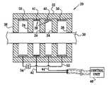
- FIG. 1is a schematic, cross-sectional illustration of an electrode assembly 20 for applying current to a nerve 30 , in accordance with an embodiment of the present invention.
- the various electrode assemblies shown in the figures and described hereingenerally contain cylindrical configurations of their elements, other geometrical configurations, such as non-rotationally symmetric configurations, are also suitable for applying the principles of the present invention.
- a housing of the electrode assemblies(and the electrodes themselves) may form a complete circle around the nerve, or it may define an arc between approximately 0 and 90 degrees, between 90 and 180 degrees, between 180 and 350 degrees, or between 350 and 359 degrees around the nerve.
- the electrode assemblies shown in the figures and described hereincomprise electrodes that form rings around the nerve, and an insulating, elastic cuff that surrounds the electrodes.
- Electrode assembly 20comprises at least one active, i.e., stimulating and/or sensing, electrode 38 , such as at least one cathode 41 and at least one anode 42 . Each of these electrodes is fixed within a housing 22 of the electrode assembly. Active electrodes 38 are coupled to an implantable or external control unit 40 by leads 42 and 44 . For some applications, active electrode configurations and/or stimulation techniques are used which are described in one or more of the patent applications incorporated by reference hereinbelow.
- Electrode assembly 20further comprises two or more passive electrodes 50 , fixed within housing 22 , and a conducting element 52 , typically a wire, which electrically couples the passive electrodes to one another.
- the electrode assemblyis configured such that the passive electrodes are electrically device-coupled, as defined hereinabove, to neither (a) any circuitry that is electrically device-coupled to the at least one cathode 41 or the at least one anode 42 , nor (b) an energy source.
- Passive electrodes 50 and conducting element 52create an electrical path for current that would otherwise leak outside electrode assembly 30 and travel around the outside of the housing through tissue of the subject.
- the active electrodesare positioned within housing 22 longitudinally between the two or more passive electrodes 50 (as shown in FIG. 1 ).
- at least one of the passive electrodesis positioned between the at least one cathode and the at least one anode (configuration not shown).
- Internal insulating elements 24which are either part of the body of the housing or affixed thereto, are typically placed so as to separate the electrodes, and to guide current from one of the electrodes towards the nerve prior to being taken up by another one of the electrodes. Typically (as shown), the insulating elements are closer to nerve 30 than are the electrodes. Alternatively (not shown), insulating elements 24 are generally flush with the faces of the electrodes.
- the electrode assemblytypically further comprises one or more end insulating elements 26 , which extend along nerve 30 in order to electrically isolate a portion of the nerve within housing 22 from a portion of the nerve outside the electrode assembly. The end insulating elements help direct any current that leaks from the active electrodes through the electrical path created by the passive electrodes and the conducting element.
- conducting element 52comprises at least one passive element 54 , such as a resistor, capacitor, and/or inductor.
- control unit 40may drive cathode 41 to apply to nerve 30 a stimulating current, which is capable of inducing action potentials in a first set and a second set of nerve fibers of the nerve, and drive anode 42 to apply to the nerve an inhibiting current, which is capable of inhibiting the induced action potentials traveling in the second set of nerve fibers, the nerve fibers in the second set having generally larger diameters than the nerve fibers in the first set.
- the electrode assemblyis configured to apply unidirectional stimulation to the nerve, such as by using techniques described in one or more of the patent applications incorporated by reference hereinbelow.
- control unit 40may drive anode 42 to apply an inhibiting current capable of inhibiting device-induced action potentials traveling in a non-therapeutic direction in nerve 30 .
- electrode assembly 20comprises primary and secondary anodes, the primary anode located between the secondary anode and the cathode.
- the secondary anodeis typically adapted to apply a current with an amplitude less than about one half an amplitude of a current applied by the primary anode.
- electrode device 20comprises one or more passive electrodes 50 which are not electrically device-coupled to one another.
- the electrode devicecomprises exactly one passive electrode 50 .
- a separate conducting elementtypically a wire, is coupled to each passive electrode at a first end of the conducting element.
- the second end of the conducting elementterminates at a relatively-remote location in the body of the subject that is at a distance of at least 1 cm, e.g., at least 2 or 3 cm, from electrode device 20 .
- the remote location in the bodythus serves as a ground for the passive electrode.
- an electrodeis coupled to the remote end of the conducting element, so as to increase electrical contact with tissue at the remote location.
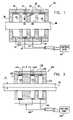
- Electrode assembly 120comprises two cathodes 141 a and 141 b and at least one anode 142 , which are fixed within a housing 122 such that no anodes are positioned between the two cathodes.
- Cathodes 141 a and 141 bare electrically coupled to one another, and are coupled to an implantable or external control unit 140 by a lead 142 .
- Anode 142is coupled to control unit 140 by a lead 144 .
- a closest distance D between the two cathodesis equal to at least a radius R of nerve 30 , e.g., at least 1.5 times the radius of the nerve.
- this electrode configurationcreates a combined cathode having an activation function a peak of which has a magnitude less than that of anode 142 , which results in a stimulation that results in unidirectional propagation of action potentials in the nerve, in the direction going from anode 142 towards the cathodes.
- this electrode configurationalso creates a virtual anode on the side of the cathodes opposite that of the anode, which results in selective fiber stimulation of fibers of the nerve having relatively small diameters.
- electrode assembly 120does not comprise any anodes on the side of the cathodes opposite anode 142 (i.e., the left side in the figures). However, for some applications, in which the virtual anode created on the side of the cathodes opposite the anode is not strong enough to create sufficient selective fiber stimulation, electrode assembly 120 comprises a second anode on the side of cathodes 141 a and 141 b opposite anode 142 . A portion of the anodal current is driven through this anode in order to strengthen the blocking of larger-diameter fibers, thereby increasing the selection of the stimulation of small-diameter fibers.
- anode 142typically, only a relatively small portion of the anodal current is driven through this second anode, in order to leave sufficient current for anode 142 to block all (or a very large portion of) action potentials generated by cathodes 141 a and 141 b (i.e., in order to preserve unidirectional stimulation).
- the electrode configuration of electrode assembly 120is combined with electrode configurations and/or stimulation techniques described in one or more of the patent applications incorporated by reference hereinbelow.
- Internal insulating elements 124which are either part of the body of the housing or affixed thereto, are typically placed so as to separate the electrodes, and to guide current from one of the electrodes towards the nerve prior to being taken up by another one of the electrodes. Typically (as shown), the insulating elements are closer to nerve 30 than are the electrodes. Alternatively (not shown), insulating elements 124 are generally flush with the faces of the electrodes.
- the electrode assemblytypically further comprises one or more end insulating elements 126 , which extend along nerve 30 in order to electrically isolate a portion of the nerve within housing 122 from a portion of the nerve outside the electrode assembly.
- Electrode assembly 220is the same as electrode assembly 120 , described hereinabove with reference to FIG. 2 , except that electrode assembly 220 further comprises, on the ends thereof, two passive electrodes 50 a and 50 b and conducting element 52 , as described hereinabove with reference to FIG. 1 .
- a closest distance between anode 142 and passive electrode 50 bis between about 0.7 mm and about 1 mm.
- Conducting element 52optionally comprises passive element 54 , as described hereinabove with reference to FIG. 1 .
- FIGS. 4 and 5are graphs modeling calculated activation functions 300 and 302 , respectively, of myelinated nerve fibers having a diameter of 1 micrometer, over a portion of the length of nerve 30 , when current is applied using an electrode assembly similar to that shown in FIG. 3 , in accordance with an embodiment of the present invention.
- activation function 302FIG. 5
- these two depolarization peakshave partially combined into a single, wide depolarization peak 308 .
- the amplitude of the hyperpolarization peakis greater than the amplitude of greatest depolarization peak, such as at least 10% or 20% greater.
- the hyperpolarization peakblocks propagation of substantially all cathode-induced action potentials traveling in the nerve from the cathode in the direction of the anode (i.e., to the right in the figures).
- This “virtual anode” effectwhich is caused by cathodes 141 a and 141 b and passive electrode 50 a , blocks propagation of almost all cathode-induced action potentials traveling in large- and medium-diameter fibers, but not those in small-diameter fibers, resulting in selective small-diameter fiber activation in the direction from cathode 141 a to passive electrode 50 a (i.e., to the left in the figures).
- This “virtual cathode” effectwhich is caused by anode 142 and passive electrode 50 b , does not generate action potentials in more than 10% of axons of nerve 30 (or does not generate action potentials in any axons of nerve 30 ) because of the virtual cathode's relatively low amplitude, and its vicinity to strong hyperpolarization peak 310 .
- cathodes 141 a and 141 bare positioned at a closest distance D less than radius R of nerve 30 ( FIG. 2 ), the cathodes begin to behave as a single cathode, generating a depolarization peak having a greater amplitude than those in activation functions 300 and 302 .
- the amplitude of hyperpolarization peak 310is no longer greater than the amplitude of the greatest depolarization peak at all nerve fiber diameters. The stimulation is thus not unidirectional at all nerve fiber diameters.
- Electrode assembly 320comprises one or more electrodes, such as at least one cathode 341 and at least one anode 342 , which are fixed within a housing 322 . Electrode assembly 320 further comprises two elongated end insulating elements 326 , which are either part of the body of the housing or affixed thereto. The end insulating elements extend along nerve 30 in order to electrically isolate a portion of the nerve within housing 322 from a portion of the nerve and other tissue outside the electrode assembly.
- Each of the end insulating elementshas a length L of at least 2 mm, such as at least 3 mm, or at least 4 mm. This elongation of the end insulating elements tends to lengthen the electrical path around the outside of the electrode assembly through tissue of the subject, thereby reducing the current that leaks from the assembly and flows through this path.
- the insulating elementshave a thickness T along at least 75% of their length of less than about 0.5 mm.
- at least one internal insulating element 324which is either part of the body of the housing or affixed thereto, is placed so as to separate the electrodes, and to guide current from one of the electrodes towards the nerve prior to being taken up by another one of the electrodes.
- FIG. 7is a schematic, cross-sectional illustration of an electrode assembly 420 for applying Electrode Array Selective Stimulation (EASS) to nerve 30 , in accordance with an embodiment of the present invention.
- EASS assembly 420comprises alternating anodes 442 and cathodes 441 .
- a control unit 440is configured to drive the electrodes of EASS assembly 420 to apply a spatially-periodic field to nerve 30 that is configured to target fibers of a selected diameter, as described in the Background of the Invention section hereinabove.
- Internal insulating elements 424which are either part of the body of the housing or affixed thereto, are typically placed so as to separate the electrodes, and to guide current from one of the electrodes towards the nerve prior to being taken up by another one of the electrodes. Typically (as shown), the insulating elements are closer to nerve 30 than are the electrodes. Alternatively (not shown), insulating elements 424 are generally flush with the faces of the electrodes.
- the electrode assemblytypically further comprises one or more end insulating elements 426 , which extend along nerve 30 in order to electrically isolate a portion of the nerve within the housing from a portion of the nerve outside the electrode assembly.
- FIG. 8is a schematic illustration of a selective stimulation EASS system 500 , in accordance with an embodiment of the present invention.
- EASS system 500comprises two EASS assemblies 420 ( FIG. 7 ), and a control unit 540 electrically coupled to both assemblies.
- the control unitconfigures one of the assemblies to function as an activating EASS assembly 510 , and the other to function as a non-stimulating EASS assembly 512 .
- one of the assembliesis permanently configured to function as activating EASS assembly 510
- the otheris permanently configured to function as non-stimulating EASS assembly 512 .
- Control unit 540drives activating EASS assembly 510 to apply a spatially-periodic stimulating field to nerve 30 , and configures the field to induce, in small fibers of the nerve, action potentials that propagate towards a target site (in the direction indicated by an arrow 546 ) and away from the target site.
- the control unitalso drives non-stimulating EASS assembly 512 to apply a spatially-periodic non-stimulating field, and to configure the field to partially depolarize the small fibers of the nerve, without initiating action potentials therein or in larger fibers of the nerve.
- the partial depolarization of the small fibersis sufficient to inhibit the action potentials generated by activating EASS assembly 510 in a direction opposite the target site from continuing to propagate beyond the inhibition site of non-stimulating EASS assembly 512 .
- unidirectional small-diameter fiber stimulationis achieved towards the target site (i.e., in the direction indicated by arrow 546 ).
- Both the stimulating and non-stimulating fieldsare typically applied using short pulses, e.g., pulses having a duration of between about 10 and about 100 microseconds.
- the amplitude of the stimulating pulsesis typically between about 0.5 and about 15 mA, depending on the number of fibers to be activated, and the amplitude of the non-stimulating pulses is typically between about 0.1 and about 5 mA, depending on the number of fibers to be blocked.
- the non-stimulating fieldis typically applied slightly before application of the stimulating field, e.g., between about 500 and about 0 microseconds earlier.
- non-stimulating EASS assembly 512causes a partial depolarization of the target axons, which causes some of the ion channels in the axons to begin their gating cycles.
- the non-stimulating fieldis configured so to minimize the likelihood of causing depolarization sufficient to trigger an action potential.
- a portion of the ion channelsenter their refractory periods. When a stimulating field is subsequently applied, these channels cannot begin the gating cycle. As a result, the number of channels available is insufficient to trigger an action potential. The fibers are therefore unable to transmit action potentials.
- the field applied by non-stimulating EASS assembly 512is configured to partially depolarize only small fibers, by using the EASS selective-fiber-diameter stimulation techniques described hereinabove.
- a pulse of a magnitude sufficient to partially depolarize small fibersmay trigger action potentials in large-diameter fibers. Therefore, without the use of the EASS partial depolarization techniques described herein, application of a conventional depolarizing pulse causes undesired complete depolarization (i.e., action potential generation) in large-diameter fibers, in addition to the desired partial depolarization of small-diameter fibers.
- applying the non-stimulating fieldcomprises applying a non-EASS non-stimulating pulse, at a strength sufficient to cause partial depolarization of target axons, but insufficient to trigger an action potential.
- EASS system 500comprises a single long EASS electrode assembly.
- the non-stimulating pulseis applied by a portion (e.g., about half) of the electrode assembly on the side thereof further from the target direction.
- the stimulating pulseis applied by the remaining portion (e.g., the other half) of the electrode assembly on the side thereof closer to the target direction.
- the stimulating pulseis applied by the entire electrode assembly, or any sufficiently long portion thereof. Use of the entire electrode device for applying the stimulating pulse generally results in a more periodic field having a lower current density.
- EASS system 500is configured to perform unidirectional stimulation of a human vagus nerve.
- the systemis configured to selectively activate only A-delta fibers, while not activating A fibers.
- the conduction velocity of A and A-delta fibersis about 20 m/sec and about 8 m/sec, respectively (see Evans M S et al., cited hereinabove). These velocities imply nodal gaps of 0.5 mm and 0.2 mm, respectively.
- the inter-electrode distance D between the respective centers of the electrodes( FIG.
- the length of a single EASS electrode with five anodes and four cathodesis typically less than about 1 cm, and two such electrodes are readily placed side-by-side on a human vagus nerve.
Landscapes
- Health & Medical Sciences (AREA)
- Life Sciences & Earth Sciences (AREA)
- General Health & Medical Sciences (AREA)
- Radiology & Medical Imaging (AREA)
- Veterinary Medicine (AREA)
- Public Health (AREA)
- Engineering & Computer Science (AREA)
- Biomedical Technology (AREA)
- Nuclear Medicine, Radiotherapy & Molecular Imaging (AREA)
- Animal Behavior & Ethology (AREA)
- Neurosurgery (AREA)
- Neurology (AREA)
- Heart & Thoracic Surgery (AREA)
- Orthopedic Medicine & Surgery (AREA)
- Cardiology (AREA)
- Biophysics (AREA)
- Electrotherapy Devices (AREA)
- Pharmaceuticals Containing Other Organic And Inorganic Compounds (AREA)
Abstract
Description
∇(σ∇U)=4πj,
- U.S. Provisional Patent Application 60/383,157 to Ayal et al., filed May 23, 2002, entitled, “Inverse recruitment for autonomic nerve systems,”
- International Patent Application PCT/IL02/00068 to Cohen et al., filed Jan. 23, 2002, entitled, “Treatment of disorders by unidirectional nerve stimulation,” and U.S. patent application Ser. No. 10/488,334, in the national stage thereof,
- U.S. patent application Ser. No. 09/944,913 to Cohen and Gross, filed Aug. 31, 2001, entitled, “Treatment of disorders by unidirectional nerve stimulation,” which issued as U.S. Pat. No. 6,684,105,
- U.S. patent application Ser. No. 09/824,682 to Cohen and Ayal, filed Apr. 4, 2001, entitled “Method and apparatus for selective control of nerve fibers,”
- U.S. patent application Ser. No. 10/205,475 to Gross et al., filed Jul. 24, 2002, entitled, “Selective nerve fiber stimulation for treating heart conditions,”
- U.S. patent application Ser. No. 10/205,474 to Gross et al., filed Jul. 24, 2002, entitled, “Electrode assembly for nerve control,” which issued as U.S. Pat. No. 6,907,295,
- International Patent Application PCT/IL03/00431 to Ayal et al., filed May 23, 2003, entitled, “Selective nerve fiber stimulation for treating heart conditions,”
- International Patent Application PCT/IL03/00430 to Ayal et al., filed May 23, 2003, entitled, “Electrode assembly for nerve control,” and U.S. patent application Ser. No. 10/529,149, in the national stage thereof,
- U.S. patent application Ser. No. 10/719,659 to Ben David et al., filed Nov. 20, 2003, entitled, “Selective nerve fiber stimulation for treating heart conditions,”
- U.S. patent application Ser. No. 11/022,011 to Cohen et al., filed Dec. 22, 2004, entitled, “Construction of electrode assembly for nerve control,” and
- U.S. patent application Ser. No. 11/234,877 to Ben-David et al., filed Sep. 22, 2005, entitled, “Selective nerve fiber stimulation.”
Claims (9)
Priority Applications (8)
| Application Number | Priority Date | Filing Date | Title |
|---|---|---|---|
| US11/280,884US7627384B2 (en) | 2004-11-15 | 2005-11-15 | Techniques for nerve stimulation |
| IL179103AIL179103A (en) | 2005-11-15 | 2006-11-07 | Apparatus for nerve stimulation |
| AT06255816TATE509660T1 (en) | 2005-11-15 | 2006-11-14 | DEVICE FOR NERVE STIMULATION |
| EP06255816AEP1785160B1 (en) | 2005-11-15 | 2006-11-14 | Apparatus for nerve stimulation |
| EP11002403AEP2340870B1 (en) | 2005-11-15 | 2006-11-14 | Apparatus for nerve stimulation |
| US12/589,132US8326438B2 (en) | 2004-11-15 | 2009-10-19 | Techniques for nerve stimulation |
| US13/661,512US8909355B2 (en) | 2004-11-15 | 2012-10-26 | Techniques for nerve stimulation |
| US14/528,665US20150057728A1 (en) | 2002-12-12 | 2014-10-30 | Efficient dynamic stimulation in an implanted device |
Applications Claiming Priority (2)
| Application Number | Priority Date | Filing Date | Title |
|---|---|---|---|
| US62839104P | 2004-11-15 | 2004-11-15 | |
| US11/280,884US7627384B2 (en) | 2004-11-15 | 2005-11-15 | Techniques for nerve stimulation |
Related Parent Applications (1)
| Application Number | Title | Priority Date | Filing Date |
|---|---|---|---|
| US13/437,114Continuation-In-PartUS8880192B2 (en) | 2002-12-12 | 2012-04-02 | Electrode cuffs |
Related Child Applications (2)
| Application Number | Title | Priority Date | Filing Date |
|---|---|---|---|
| US12/589,132DivisionUS8326438B2 (en) | 2002-12-12 | 2009-10-19 | Techniques for nerve stimulation |
| US12/589,132ContinuationUS8326438B2 (en) | 2002-12-12 | 2009-10-19 | Techniques for nerve stimulation |
Publications (2)
| Publication Number | Publication Date |
|---|---|
| US20060106441A1 US20060106441A1 (en) | 2006-05-18 |
| US7627384B2true US7627384B2 (en) | 2009-12-01 |
Family
ID=37685290
Family Applications (3)
| Application Number | Title | Priority Date | Filing Date |
|---|---|---|---|
| US11/280,884Active2028-08-09US7627384B2 (en) | 2002-12-12 | 2005-11-15 | Techniques for nerve stimulation |
| US12/589,132Expired - Fee RelatedUS8326438B2 (en) | 2002-12-12 | 2009-10-19 | Techniques for nerve stimulation |
| US13/661,512Expired - Fee RelatedUS8909355B2 (en) | 2002-12-12 | 2012-10-26 | Techniques for nerve stimulation |
Family Applications After (2)
| Application Number | Title | Priority Date | Filing Date |
|---|---|---|---|
| US12/589,132Expired - Fee RelatedUS8326438B2 (en) | 2002-12-12 | 2009-10-19 | Techniques for nerve stimulation |
| US13/661,512Expired - Fee RelatedUS8909355B2 (en) | 2002-12-12 | 2012-10-26 | Techniques for nerve stimulation |
Country Status (4)
| Country | Link |
|---|---|
| US (3) | US7627384B2 (en) |
| EP (2) | EP2340870B1 (en) |
| AT (1) | ATE509660T1 (en) |
| IL (1) | IL179103A (en) |
Cited By (45)
| Publication number | Priority date | Publication date | Assignee | Title |
|---|---|---|---|---|
| WO2012088482A1 (en) | 2010-12-23 | 2012-06-28 | Boston Scientific Neuromodulation Corporation | Neurostimulation system for estimating desired stimulation amplitude for electrode configuration |
| US8565896B2 (en) | 2010-11-22 | 2013-10-22 | Bio Control Medical (B.C.M.) Ltd. | Electrode cuff with recesses |
| US8571654B2 (en) | 2012-01-17 | 2013-10-29 | Cyberonics, Inc. | Vagus nerve neurostimulator with multiple patient-selectable modes for treating chronic cardiac dysfunction |
| US8571653B2 (en) | 2001-08-31 | 2013-10-29 | Bio Control Medical (B.C.M.) Ltd. | Nerve stimulation techniques |
| US8571651B2 (en) | 2006-09-07 | 2013-10-29 | Bio Control Medical (B.C.M.) Ltd. | Techniques for reducing pain associated with nerve stimulation |
| US8577458B1 (en) | 2011-12-07 | 2013-11-05 | Cyberonics, Inc. | Implantable device for providing electrical stimulation of cervical vagus nerves for treatment of chronic cardiac dysfunction with leadless heart rate monitoring |
| US8600505B2 (en) | 2011-12-07 | 2013-12-03 | Cyberonics, Inc. | Implantable device for facilitating control of electrical stimulation of cervical vagus nerves for treatment of chronic cardiac dysfunction |
| US8630709B2 (en) | 2011-12-07 | 2014-01-14 | Cyberonics, Inc. | Computer-implemented system and method for selecting therapy profiles of electrical stimulation of cervical vagus nerves for treatment of chronic cardiac dysfunction |
| US8688212B2 (en) | 2012-07-20 | 2014-04-01 | Cyberonics, Inc. | Implantable neurostimulator-implemented method for managing bradycardia through vagus nerve stimulation |
| US8700150B2 (en) | 2012-01-17 | 2014-04-15 | Cyberonics, Inc. | Implantable neurostimulator for providing electrical stimulation of cervical vagus nerves for treatment of chronic cardiac dysfunction with bounded titration |
| US8880192B2 (en) | 2012-04-02 | 2014-11-04 | Bio Control Medical (B.C.M.) Ltd. | Electrode cuffs |
| US8918191B2 (en) | 2011-12-07 | 2014-12-23 | Cyberonics, Inc. | Implantable device for providing electrical stimulation of cervical vagus nerves for treatment of chronic cardiac dysfunction with bounded titration |
| US8918190B2 (en) | 2011-12-07 | 2014-12-23 | Cyberonics, Inc. | Implantable device for evaluating autonomic cardiovascular drive in a patient suffering from chronic cardiac dysfunction |
| US8923964B2 (en) | 2012-11-09 | 2014-12-30 | Cyberonics, Inc. | Implantable neurostimulator-implemented method for enhancing heart failure patient awakening through vagus nerve stimulation |
| US9272143B2 (en) | 2014-05-07 | 2016-03-01 | Cyberonics, Inc. | Responsive neurostimulation for the treatment of chronic cardiac dysfunction |
| US9381359B2 (en) | 2014-02-05 | 2016-07-05 | Boston Scientific Neuromodulation Corporation | System and method for delivering modulated sub-threshold therapy to a patient |
| US9381360B2 (en) | 2014-02-05 | 2016-07-05 | Boston Scientific Neuromodulation Corporation | System and method for delivering modulated sub-threshold therapy to a patient |
| US9409024B2 (en) | 2014-03-25 | 2016-08-09 | Cyberonics, Inc. | Neurostimulation in a neural fulcrum zone for the treatment of chronic cardiac dysfunction |
| US9415224B2 (en) | 2014-04-25 | 2016-08-16 | Cyberonics, Inc. | Neurostimulation and recording of physiological response for the treatment of chronic cardiac dysfunction |
| US9452290B2 (en) | 2012-11-09 | 2016-09-27 | Cyberonics, Inc. | Implantable neurostimulator-implemented method for managing tachyarrhythmia through vagus nerve stimulation |
| US9504832B2 (en) | 2014-11-12 | 2016-11-29 | Cyberonics, Inc. | Neurostimulation titration process via adaptive parametric modification |
| US9511228B2 (en) | 2014-01-14 | 2016-12-06 | Cyberonics, Inc. | Implantable neurostimulator-implemented method for managing hypertension through renal denervation and vagus nerve stimulation |
| US9533153B2 (en) | 2014-08-12 | 2017-01-03 | Cyberonics, Inc. | Neurostimulation titration process |
| US9616230B2 (en) | 2013-12-12 | 2017-04-11 | Boston Scientific Neuromodulation Corporation | Systems and methods for programming a neuromodulation system |
| US9643008B2 (en) | 2012-11-09 | 2017-05-09 | Cyberonics, Inc. | Implantable neurostimulator-implemented method for enhancing post-exercise recovery through vagus nerve stimulation |
| US9643011B2 (en) | 2013-03-14 | 2017-05-09 | Cyberonics, Inc. | Implantable neurostimulator-implemented method for managing tachyarrhythmic risk during sleep through vagus nerve stimulation |
| US9713719B2 (en) | 2014-04-17 | 2017-07-25 | Cyberonics, Inc. | Fine resolution identification of a neural fulcrum for the treatment of chronic cardiac dysfunction |
| US9737716B2 (en) | 2014-08-12 | 2017-08-22 | Cyberonics, Inc. | Vagus nerve and carotid baroreceptor stimulation system |
| US9770599B2 (en) | 2014-08-12 | 2017-09-26 | Cyberonics, Inc. | Vagus nerve stimulation and subcutaneous defibrillation system |
| US9827422B2 (en) | 2015-05-28 | 2017-11-28 | Boston Scientific Neuromodulation Corporation | Neuromodulation using stochastically-modulated stimulation parameters |
| US9950169B2 (en) | 2014-04-25 | 2018-04-24 | Cyberonics, Inc. | Dynamic stimulation adjustment for identification of a neural fulcrum |
| US9956393B2 (en) | 2015-02-24 | 2018-05-01 | Elira, Inc. | Systems for increasing a delay in the gastric emptying time for a patient using a transcutaneous electro-dermal patch |
| US9999773B2 (en) | 2013-10-30 | 2018-06-19 | Cyberonics, Inc. | Implantable neurostimulator-implemented method utilizing multi-modal stimulation parameters |
| US10010715B2 (en) | 2013-12-04 | 2018-07-03 | Boston Scientific Neuromodulation Corporation | Systems and methods for delivering therapy to the dorsal horn of a patient |
| US10118035B2 (en) | 2015-02-24 | 2018-11-06 | Elira, Inc. | Systems and methods for enabling appetite modulation and/or improving dietary compliance using an electro-dermal patch |
| US10118040B2 (en) | 2013-03-08 | 2018-11-06 | Boston Scientific Neuromodulation Corporation | Neuromodulation using modulated pulse train |
| US10188856B1 (en) | 2011-12-07 | 2019-01-29 | Cyberonics, Inc. | Implantable device for providing electrical stimulation of cervical vagus nerves for treatment of chronic cardiac dysfunction |
| US10335302B2 (en) | 2015-02-24 | 2019-07-02 | Elira, Inc. | Systems and methods for using transcutaneous electrical stimulation to enable dietary interventions |
| US10376145B2 (en) | 2015-02-24 | 2019-08-13 | Elira, Inc. | Systems and methods for enabling a patient to achieve a weight loss objective using an electrical dermal patch |
| US10765863B2 (en) | 2015-02-24 | 2020-09-08 | Elira, Inc. | Systems and methods for using a transcutaneous electrical stimulation device to deliver titrated therapy |
| US10864367B2 (en) | 2015-02-24 | 2020-12-15 | Elira, Inc. | Methods for using an electrical dermal patch in a manner that reduces adverse patient reactions |
| US11382550B2 (en) | 2018-02-28 | 2022-07-12 | Medtronic Xomed, Inc. | Nerve monitoring and/or stimulation electrode assemblies |
| US11412986B2 (en)* | 2017-10-06 | 2022-08-16 | Medtronic Xomed, Inc. | Methods of recording responses of and stimulating bioelectric tissue |
| US11957895B2 (en) | 2015-02-24 | 2024-04-16 | Elira, Inc. | Glucose-based modulation of electrical stimulation to enable weight loss |
| US12427310B2 (en) | 2016-09-29 | 2025-09-30 | Theranica Bio-Electronics Ltd. | Application of an electrical amplitude-modulated signal to a subject |
Families Citing this family (29)
| Publication number | Priority date | Publication date | Assignee | Title |
|---|---|---|---|---|
| US6907295B2 (en) | 2001-08-31 | 2005-06-14 | Biocontrol Medical Ltd. | Electrode assembly for nerve control |
| US7778711B2 (en)* | 2001-08-31 | 2010-08-17 | Bio Control Medical (B.C.M.) Ltd. | Reduction of heart rate variability by parasympathetic stimulation |
| US20140046407A1 (en)* | 2001-08-31 | 2014-02-13 | Bio Control Medical (B.C.M.) Ltd. | Nerve stimulation techniques |
| US8615294B2 (en)* | 2008-08-13 | 2013-12-24 | Bio Control Medical (B.C.M.) Ltd. | Electrode devices for nerve stimulation and cardiac sensing |
| US7844346B2 (en) | 2002-05-23 | 2010-11-30 | Biocontrol Medical Ltd. | Electrode assembly for nerve control |
| US8204591B2 (en) | 2002-05-23 | 2012-06-19 | Bio Control Medical (B.C.M.) Ltd. | Techniques for prevention of atrial fibrillation |
| US7627384B2 (en) | 2004-11-15 | 2009-12-01 | Bio Control Medical (B.C.M.) Ltd. | Techniques for nerve stimulation |
| US8718791B2 (en) | 2003-05-23 | 2014-05-06 | Bio Control Medical (B.C.M.) Ltd. | Electrode cuffs |
| US20100010603A1 (en) | 2008-07-09 | 2010-01-14 | Tamir Ben-David | Electrode cuffs |
| US8116881B2 (en) | 2004-06-10 | 2012-02-14 | Bio Control Medical (B.C.M.) Ltd | Electrode assembly for nerve control |
| WO2007117651A2 (en)* | 2006-04-07 | 2007-10-18 | University Of South Florida | Passive electric field focus system for in vivo and in vitro applications |
| US20080086180A1 (en)* | 2006-10-05 | 2008-04-10 | Omry Ben-Ezra | Techniques for gall bladder stimulation |
| US8457757B2 (en) | 2007-11-26 | 2013-06-04 | Micro Transponder, Inc. | Implantable transponder systems and methods |
| US9089707B2 (en) | 2008-07-02 | 2015-07-28 | The Board Of Regents, The University Of Texas System | Systems, methods and devices for paired plasticity |
| US9717910B2 (en)* | 2008-09-04 | 2017-08-01 | Boston Scientific Neuromodulation Corporation | Multiple tunable central cathodes on a paddle for increased medial-lateral and rostral-caudal flexibility via current steering |
| US9504818B2 (en)* | 2008-09-04 | 2016-11-29 | Boston Scientific Neuromodulation Corporation | Multiple tunable central cathodes on a paddle for increased medial-lateral and rostral-caudal flexibility via current steering |
| US9802046B2 (en) | 2008-10-03 | 2017-10-31 | Duke University | Non-regular electrical stimulation patterns for improved efficiency in treating Parkinson's Disease |
| US8923981B2 (en) | 2008-10-03 | 2014-12-30 | Duke University | Non-regular electrical stimulation patterns designed with a cost function for treating neurological disorders |
| US11013924B2 (en) | 2008-10-03 | 2021-05-25 | Duke University | Non-regular electrical stimulation patterns for treating neurological disorders |
| CA3178974A1 (en) | 2008-10-03 | 2010-04-08 | Duke University | Non-regular electrical stimulation patterns for treating neurological disorders |
| US8798755B2 (en) | 2008-10-03 | 2014-08-05 | Duke University | Non-regular electrical stimulation patterns for treating neurological disorders |
| JP5847167B2 (en) | 2010-05-27 | 2016-01-20 | エヌディーアイ メディカル, エルエルシー | Waveform shapes for neurological disorder treatment optimized for energy efficiency |
| US9089684B2 (en) | 2012-02-13 | 2015-07-28 | Axelgaard Manufacturing Company, Ltd. | Dual-sided current controlling electrode |
| CA2916241C (en) | 2013-05-22 | 2023-07-04 | Deep Brain Innovations LLC | Deep brain stimulator and method of use |
| AU2014369910B2 (en) | 2013-12-23 | 2019-05-16 | Deep Brain Innovations LLC | Programming systems for deep brain stimulator system |
| DE102014104414A1 (en)* | 2014-03-28 | 2015-10-01 | Roland Mäusl | Nerve stimulation device |
| EP3434321A1 (en)* | 2017-07-26 | 2019-01-30 | BIOTRONIK SE & Co. KG | Neural stimulation and recording, particularly for neuromodulation closed-loop control |
| US20220257935A1 (en)* | 2021-02-18 | 2022-08-18 | Duke University | Systems and methods for nerve fiber conduction block |
| US11400299B1 (en) | 2021-09-14 | 2022-08-02 | Rainbow Medical Ltd. | Flexible antenna for stimulator |
Citations (154)
| Publication number | Priority date | Publication date | Assignee | Title |
|---|---|---|---|---|
| US3411507A (en) | 1964-04-01 | 1968-11-19 | Medtronic Inc | Method of gastrointestinal stimulation with electrical pulses |
| US4019518A (en) | 1975-08-11 | 1977-04-26 | Medtronic, Inc. | Electrical stimulation system |
| US4161952A (en) | 1977-11-01 | 1979-07-24 | Mieczyslaw Mirowski | Wound wire catheter cardioverting electrode |
| US4338945A (en) | 1978-03-03 | 1982-07-13 | Clinical Engineering Laboratory Limited | Method and randomized electrical stimulation system for pain relief |
| US4392496A (en) | 1981-03-13 | 1983-07-12 | Medtronic, Inc. | Neuromuscular stimulator |
| US4535785A (en) | 1982-09-23 | 1985-08-20 | Minnesota Mining And Manufacturing Co. | Method and apparatus for determining the viability and survival of sensori-neutral elements within the inner ear |
| US4559948A (en) | 1984-01-09 | 1985-12-24 | Pain Suppression Labs | Cerebral palsy treatment apparatus and methodology |
| US4573481A (en) | 1984-06-25 | 1986-03-04 | Huntington Institute Of Applied Research | Implantable electrode array |
| US4585005A (en) | 1984-04-06 | 1986-04-29 | Regents Of University Of California | Method and pacemaker for stimulating penile erection |
| US4602624A (en) | 1984-10-11 | 1986-07-29 | Case Western Reserve University | Implantable cuff, method of manufacture, and method of installation |
| US4608985A (en) | 1984-10-11 | 1986-09-02 | Case Western Reserve University | Antidromic pulse generating wave form for collision blocking |
| US4628942A (en) | 1984-10-11 | 1986-12-16 | Case Western Reserve University | Asymmetric shielded two electrode cuff |
| US4632116A (en) | 1984-06-29 | 1986-12-30 | Rosen Joseph M | Microelectronic axon processor |
| US4649936A (en) | 1984-10-11 | 1987-03-17 | Case Western Reserve University | Asymmetric single electrode cuff for generation of unidirectionally propagating action potentials for collision blocking |
| US4663102A (en) | 1982-12-22 | 1987-05-05 | Biosonics, Inc. | Method of making a body member for use in a genital stimulator |
| US4702254A (en) | 1983-09-14 | 1987-10-27 | Jacob Zabara | Neurocybernetic prosthesis |
| US4739764A (en) | 1984-05-18 | 1988-04-26 | The Regents Of The University Of California | Method for stimulating pelvic floor muscles for regulating pelvic viscera |
| US4867164A (en) | 1983-09-14 | 1989-09-19 | Jacob Zabara | Neurocybernetic prosthesis |
| US4926865A (en) | 1987-10-01 | 1990-05-22 | Oman Paul S | Microcomputer-based nerve and muscle stimulator |
| US4962751A (en) | 1989-05-30 | 1990-10-16 | Welch Allyn, Inc. | Hydraulic muscle pump |
| US5025807A (en) | 1983-09-14 | 1991-06-25 | Jacob Zabara | Neurocybernetic prosthesis |
| US5042497A (en) | 1990-01-30 | 1991-08-27 | Cardiac Pacemakers, Inc. | Arrhythmia prediction and prevention for implanted devices |
| US5069680A (en) | 1989-12-06 | 1991-12-03 | Medtronic, Inc. | Muscle stimulator with variable duty cycle |
| US5170802A (en) | 1991-01-07 | 1992-12-15 | Medtronic, Inc. | Implantable electrode for location within a blood vessel |
| US5178161A (en) | 1988-09-02 | 1993-01-12 | The Board Of Trustees Of The Leland Stanford Junior University | Microelectronic interface |
| US5188104A (en) | 1991-02-01 | 1993-02-23 | Cyberonics, Inc. | Treatment of eating disorders by nerve stimulation |
| US5199428A (en) | 1991-03-22 | 1993-04-06 | Medtronic, Inc. | Implantable electrical nerve stimulator/pacemaker with ischemia for decreasing cardiac workload |
| US5199430A (en) | 1991-03-11 | 1993-04-06 | Case Western Reserve University | Micturitional assist device |
| US5203326A (en) | 1991-12-18 | 1993-04-20 | Telectronics Pacing Systems, Inc. | Antiarrhythmia pacer using antiarrhythmia pacing and autonomic nerve stimulation therapy |
| US5205285A (en) | 1991-06-14 | 1993-04-27 | Cyberonics, Inc. | Voice suppression of vagal stimulation |
| US5215086A (en) | 1991-05-03 | 1993-06-01 | Cyberonics, Inc. | Therapeutic treatment of migraine symptoms by stimulation |
| US5224491A (en) | 1991-01-07 | 1993-07-06 | Medtronic, Inc. | Implantable electrode for location within a blood vessel |
| US5243980A (en) | 1992-06-30 | 1993-09-14 | Medtronic, Inc. | Method and apparatus for discrimination of ventricular and supraventricular tachycardia |
| US5263480A (en) | 1991-02-01 | 1993-11-23 | Cyberonics, Inc. | Treatment of eating disorders by nerve stimulation |
| US5282468A (en) | 1990-06-07 | 1994-02-01 | Medtronic, Inc. | Implantable neural electrode |
| US5292344A (en) | 1992-07-10 | 1994-03-08 | Douglas Donald D | Percutaneously placed electrical gastrointestinal pacemaker stimulatory system, sensing system, and pH monitoring system, with optional delivery port |
| US5299569A (en) | 1991-05-03 | 1994-04-05 | Cyberonics, Inc. | Treatment of neuropsychiatric disorders by nerve stimulation |
| US5330507A (en) | 1992-04-24 | 1994-07-19 | Medtronic, Inc. | Implantable electrical vagal stimulation for prevention or interruption of life threatening arrhythmias |
| US5334221A (en) | 1992-06-30 | 1994-08-02 | Medtronic, Inc. | Method and apparatus for treatment of angina same |
| US5335657A (en) | 1991-05-03 | 1994-08-09 | Cyberonics, Inc. | Therapeutic treatment of sleep disorder by nerve stimulation |
| US5356425A (en) | 1992-06-30 | 1994-10-18 | Medtronic, Inc. | Method and apparatus for treatment of atrial fibrillation and flutter |
| US5411531A (en) | 1993-09-23 | 1995-05-02 | Medtronic, Inc. | Method and apparatus for control of A-V interval |
| US5423872A (en) | 1992-05-29 | 1995-06-13 | Cigaina; Valerio | Process and device for treating obesity and syndromes related to motor disorders of the stomach of a patient |
| US5437285A (en) | 1991-02-20 | 1995-08-01 | Georgetown University | Method and apparatus for prediction of sudden cardiac death by simultaneous assessment of autonomic function and cardiac electrical stability |
| US5439938A (en) | 1993-04-07 | 1995-08-08 | The Johns Hopkins University | Treatments for male sexual dysfunction |
| US5454840A (en) | 1994-04-05 | 1995-10-03 | Krakovsky; Alexander A. | Potency package |
| EP0688577A1 (en) | 1994-06-24 | 1995-12-27 | Pacesetter AB | Device for treating atrial tachyarrhythmia |
| US5487756A (en)* | 1994-12-23 | 1996-01-30 | Simon Fraser University | Implantable cuff having improved closure |
| US5522854A (en) | 1994-05-19 | 1996-06-04 | Duke University | Method and apparatus for the prevention of arrhythmia by nerve stimulation |
| US5540734A (en) | 1994-09-28 | 1996-07-30 | Zabara; Jacob | Cranial nerve stimulation treatments using neurocybernetic prosthesis |
| US5540730A (en) | 1995-06-06 | 1996-07-30 | Cyberonics, Inc. | Treatment of motility disorders by nerve stimulation |
| US5562718A (en) | 1994-06-03 | 1996-10-08 | Palermo; Francis X. | Electronic neuromuscular stimulation device |
| US5571150A (en) | 1994-12-19 | 1996-11-05 | Cyberonics, Inc. | Treatment of patients in coma by nerve stimulation |
| US5578061A (en) | 1994-06-24 | 1996-11-26 | Pacesetter Ab | Method and apparatus for cardiac therapy by stimulation of a physiological representative of the parasympathetic nervous system |
| US5634462A (en) | 1993-10-15 | 1997-06-03 | Case Western Reserve University | Corrugated inter-fascicular nerve cuff method and apparatus |
| US5645570A (en) | 1992-03-26 | 1997-07-08 | Sorin Biomedica S.P.A. | Method and device for monitoring and detecting sympatho-vagal activity and for providing therapy in response thereto |
| US5658318A (en) | 1994-06-24 | 1997-08-19 | Pacesetter Ab | Method and apparatus for detecting a state of imminent cardiac arrhythmia in response to a nerve signal from the autonomic nerve system to the heart, and for administrating anti-arrhythmia therapy in response thereto |
| US5690691A (en) | 1996-05-08 | 1997-11-25 | The Center For Innovative Technology | Gastro-intestinal pacemaker having phased multi-point stimulation |
| US5690681A (en) | 1996-03-29 | 1997-11-25 | Purdue Research Foundation | Method and apparatus using vagal stimulation for control of ventricular rate during atrial fibrillation |
| US5700282A (en) | 1995-10-13 | 1997-12-23 | Zabara; Jacob | Heart rhythm stabilization using a neurocybernetic prosthesis |
| US5707400A (en) | 1995-09-19 | 1998-01-13 | Cyberonics, Inc. | Treating refractory hypertension by nerve stimulation |
| US5711316A (en) | 1996-04-30 | 1998-01-27 | Medtronic, Inc. | Method of treating movement disorders by brain infusion |
| US5716385A (en) | 1996-11-12 | 1998-02-10 | University Of Virginia | Crural diaphragm pacemaker and method for treating esophageal reflux disease |
| US5755750A (en) | 1995-11-13 | 1998-05-26 | University Of Florida | Method and apparatus for selectively inhibiting activity in nerve fibers |
| US5824027A (en) | 1997-08-14 | 1998-10-20 | Simon Fraser University | Nerve cuff having one or more isolated chambers |
| US5833709A (en) | 1996-04-25 | 1998-11-10 | Medtronic, Inc. | Method of treating movement disorders by brain stimulation |
| US5836994A (en) | 1997-04-30 | 1998-11-17 | Medtronic, Inc. | Method and apparatus for electrical stimulation of the gastrointestinal tract |
| US5938596A (en) | 1997-03-17 | 1999-08-17 | Medtronic, Inc. | Medical electrical lead |
| US5938584A (en) | 1997-11-14 | 1999-08-17 | Cybernetic Medical Systems Corporation | Cavernous nerve stimulation device |
| US6006134A (en) | 1998-04-30 | 1999-12-21 | Medtronic, Inc. | Method and device for electronically controlling the beating of a heart using venous electrical stimulation of nerve fibers |
| US6026326A (en) | 1997-01-13 | 2000-02-15 | Medtronic, Inc. | Apparatus and method for treating chronic constipation |
| US6058331A (en) | 1998-04-27 | 2000-05-02 | Medtronic, Inc. | Apparatus and method for treating peripheral vascular disease and organ ischemia by electrical stimulation with closed loop feedback control |
| US6066163A (en) | 1996-02-02 | 2000-05-23 | John; Michael Sasha | Adaptive brain stimulation method and system |
| US6073048A (en) | 1995-11-17 | 2000-06-06 | Medtronic, Inc. | Baroreflex modulation with carotid sinus nerve stimulation for the treatment of heart failure |
| US6086525A (en) | 1994-11-28 | 2000-07-11 | Neotonus, Inc. | Magnetic nerve stimulator for exciting peripheral nerves |
| US6091977A (en) | 1995-04-07 | 2000-07-18 | The University Of Miami | Sensor |
| US6091992A (en) | 1997-12-15 | 2000-07-18 | Medtronic, Inc. | Method and apparatus for electrical stimulation of the gastrointestinal tract |
| US6094598A (en) | 1996-04-25 | 2000-07-25 | Medtronics, Inc. | Method of treating movement disorders by brain stimulation and drug infusion |
| US6097984A (en) | 1998-11-25 | 2000-08-01 | Medtronic, Inc. | System and method of stimulation for treating gastro-esophageal reflux disease |
| US6104955A (en) | 1997-12-15 | 2000-08-15 | Medtronic, Inc. | Method and apparatus for electrical stimulation of the gastrointestinal tract |
| US6104960A (en) | 1998-07-13 | 2000-08-15 | Medtronic, Inc. | System and method for providing medical electrical stimulation to a portion of the nervous system |
| US6119516A (en) | 1997-05-23 | 2000-09-19 | Advantedge Systems, Inc. | Biofeedback system for monitoring the motion of body joint |
| USH1905H (en) | 1997-03-21 | 2000-10-03 | Medtronic, Inc. | Mechanism for adjusting the exposed surface area and position of an electrode along a lead body |
| US6134470A (en) | 1998-11-09 | 2000-10-17 | Medtronic, Inc. | Method and apparatus for treating a tachyarrhythmic patient |
| US6146335A (en) | 1997-07-01 | 2000-11-14 | Neurometrix, Inc. | Apparatus for methods for the assessment of neuromuscular function of the lower extremity |
| US6161029A (en) | 1999-03-08 | 2000-12-12 | Medtronic, Inc. | Apparatus and method for fixing electrodes in a blood vessel |
| US6167304A (en) | 1993-05-28 | 2000-12-26 | Loos; Hendricus G. | Pulse variability in electric field manipulation of nervous systems |
| US6169924B1 (en) | 1999-04-27 | 2001-01-02 | T. Stuart Meloy | Spinal cord stimulation |
| WO2001010432A1 (en) | 1999-08-10 | 2001-02-15 | Uab Research Foundation | Use of gaba agonists for treatment of spastic disorders, convulsions, and epilepsy |
| US6205359B1 (en) | 1998-10-26 | 2001-03-20 | Birinder Bob Boveja | Apparatus and method for adjunct (add-on) therapy of partial complex epilepsy, generalized epilepsy and involuntary movement disorders utilizing an external stimulator |
| WO2001026729A1 (en) | 1999-10-13 | 2001-04-19 | Cyberonics, Inc. | Method to enhance cardiac capillary growth in heart failure patients |
| US6230061B1 (en) | 1996-03-01 | 2001-05-08 | Biotronik Mess—und Therapiegerate GmbH & Co. Ingenieurburo Berlin | Electrode arrangement |
| US6240314B1 (en) | 1999-01-28 | 2001-05-29 | Sorin Biomedica Cardio S.P.A. | Heart stimulation device with electrotonic inhibition |
| US6272377B1 (en) | 1999-10-01 | 2001-08-07 | Cardiac Pacemakers, Inc. | Cardiac rhythm management system with arrhythmia prediction and prevention |
| WO2001010375A3 (en) | 1999-08-04 | 2001-08-16 | Impulse Dynamics Nv | Inhibition of action potentials |
| US6292695B1 (en) | 1998-06-19 | 2001-09-18 | Wilton W. Webster, Jr. | Method and apparatus for transvascular treatment of tachycardia and fibrillation |
| US6319241B1 (en) | 1998-04-30 | 2001-11-20 | Medtronic, Inc. | Techniques for positioning therapy delivery elements within a spinal cord or a brain |
| US6341236B1 (en) | 1999-04-30 | 2002-01-22 | Ivan Osorio | Vagal nerve stimulation techniques for treatment of epileptic seizures |
| US6356784B1 (en) | 1999-04-30 | 2002-03-12 | Medtronic, Inc. | Method of treating movement disorders by electrical stimulation and/or drug infusion of the pendunulopontine nucleus |
| US20020035335A1 (en) | 1999-11-30 | 2002-03-21 | Patrick Schauerte | Implantable device for diagnosing and distinguishing supraventricular and ventricular tachycardias |
| US6366813B1 (en) | 1998-08-05 | 2002-04-02 | Dilorenzo Daniel J. | Apparatus and method for closed-loop intracranical stimulation for optimal control of neurological disease |
| US6381499B1 (en) | 1996-02-20 | 2002-04-30 | Cardiothoracic Systems, Inc. | Method and apparatus for using vagus nerve stimulation in surgery |
| US6405079B1 (en) | 2000-09-22 | 2002-06-11 | Mehdi M. Ansarinia | Stimulation method for the dural venous sinuses and adjacent dura for treatment of medical conditions |
| US20020107553A1 (en) | 2000-10-26 | 2002-08-08 | Medtronic, Inc. | Method and apparatus for electrically stimulating the nervous system to improve ventricular dysfunction, heart failure, and other cardiac conditions |
| US6434424B1 (en) | 1998-12-28 | 2002-08-13 | Medtronic, Inc. | Regularization of ventricular rate during atrial tachyarrhythmia |
| US20020120304A1 (en) | 2001-02-28 | 2002-08-29 | Mest Robert A. | Method and system for treatment of tachycardia and fibrillation |
| US6449507B1 (en) | 1996-04-30 | 2002-09-10 | Medtronic, Inc. | Method and system for nerve stimulation prior to and during a medical procedure |
| US6456866B1 (en) | 1999-09-28 | 2002-09-24 | Dustin Tyler | Flat interface nerve electrode and a method for use |
| US6463328B1 (en) | 1996-02-02 | 2002-10-08 | Michael Sasha John | Adaptive brain stimulation method and system |
| WO2002085448A2 (en) | 2001-04-20 | 2002-10-31 | The Board Of Regents Of The University Of Oklahoma | Cardiac neuromodulation and methods of using same |
| US20030018367A1 (en) | 2001-07-23 | 2003-01-23 | Dilorenzo Daniel John | Method and apparatus for neuromodulation and phsyiologic modulation for the treatment of metabolic and neuropsychiatric disease |
| US6511500B1 (en) | 2000-06-06 | 2003-01-28 | Marc Mounir Rahme | Use of autonomic nervous system neurotransmitters inhibition and atrial parasympathetic fibers ablation for the treatment of atrial arrhythmias and to preserve drug effects |
| US20030040774A1 (en) | 2001-08-21 | 2003-02-27 | Terry Reese S. | Treatment of congestive heart failure and autonomic cardiovascular drive disorders |
| US20030045909A1 (en) | 2001-08-31 | 2003-03-06 | Biocontrol Medical Ltd. | Selective nerve fiber stimulation for treating heart conditions |
| US20030050677A1 (en) | 2001-08-31 | 2003-03-13 | Biocontrol Medical Ltd. | Electrode assembly for nerve control |
| US20030078623A1 (en) | 2001-10-22 | 2003-04-24 | Weinberg Lisa P. | Implantable lead and method for stimulating the vagus nerve |
| US20030097221A1 (en) | 2001-10-12 | 2003-05-22 | Daniel Chun | Detection and characterization of psychoactives using parallel multi-site assays in brain tissue |
| US6600956B2 (en) | 2001-08-21 | 2003-07-29 | Cyberonics, Inc. | Circumneural electrode assembly |
| US6610713B2 (en) | 2000-05-23 | 2003-08-26 | North Shore - Long Island Jewish Research Institute | Inhibition of inflammatory cytokine production by cholinergic agonists and vagus nerve stimulation |
| US6628987B1 (en) | 2000-09-26 | 2003-09-30 | Medtronic, Inc. | Method and system for sensing cardiac contractions during vagal stimulation-induced cardiopalegia |
| US20030216775A1 (en) | 2000-09-26 | 2003-11-20 | Hill Michael R.S. | Method and system for directing blood flow during a medical procedure |
| US20030229380A1 (en) | 2002-10-31 | 2003-12-11 | Adams John M. | Heart failure therapy device and method |
| US20030233129A1 (en) | 2002-06-11 | 2003-12-18 | Matos Jeffrey A. | System for cardiac resuscitation |
| US6668191B1 (en) | 1998-10-26 | 2003-12-23 | Birinder R. Boveja | Apparatus and method for electrical stimulation adjunct (add-on) therapy of atrial fibrillation, inappropriate sinus tachycardia, and refractory hypertension with an external stimulator |
| US20030236558A1 (en) | 2002-06-20 | 2003-12-25 | Whitehurst Todd K. | Vagus nerve stimulation via unidirectional propagation of action potentials |
| US6684105B2 (en) | 2001-08-31 | 2004-01-27 | Biocontrol Medical, Ltd. | Treatment of disorders by unidirectional nerve stimulation |
| EP0831954B1 (en) | 1995-06-09 | 2004-03-03 | Medtronic, Inc. | Apparatus for variable rate cardiac stimulation |
| US20040048795A1 (en) | 2002-02-26 | 2004-03-11 | North Shore-Long Island Jewish Research Institute | Inhibition of inflammatory cytokine production by stimulation of brain muscarinic receptors |
| US20040059392A1 (en) | 2002-06-28 | 2004-03-25 | Jordi Parramon | Microstimulator having self-contained power source |
| US20040152958A1 (en) | 2002-10-15 | 2004-08-05 | Medtronic, Inc. | Timed delay for redelivery of treatment therapy for a medical device system |
| US20040158119A1 (en) | 2002-10-15 | 2004-08-12 | Medtronic, Inc. | Screening techniques for management of a nervous system disorder |
| US20040162594A1 (en) | 2001-05-17 | 2004-08-19 | King Gary W. | Apparatus and method for blocking activation of tissue or conduction of action potentials while other tissue is being therapeutically activated |
| US20040172075A1 (en) | 1996-04-30 | 2004-09-02 | Shafer Lisa L. | Method and system for vagal nerve stimulation with multi-site cardiac pacing |
| US20040199210A1 (en) | 2002-06-12 | 2004-10-07 | Shelchuk Anne M. | Vagal stimulation for improving cardiac function in heart failure or CHF patients |
| US20040215289A1 (en) | 2002-12-04 | 2004-10-28 | Terumo Kabushiki Kaisha | Heart treatment equipment and method for preventing fatal arrhythmia |
| US20040243182A1 (en) | 2001-08-31 | 2004-12-02 | Ehud Cohen | Treatment of disorders by unidirectional nerve stimulation |
| US20040249416A1 (en) | 2003-06-09 | 2004-12-09 | Yun Anthony Joonkyoo | Treatment of conditions through electrical modulation of the autonomic nervous system |
| USRE38705E1 (en) | 1996-04-30 | 2005-02-22 | Medtronic, Inc. | Method and device for electronically controlling the beating of a heart using venous electrical stimulation of nerve fibers |
| US6865416B2 (en) | 1998-05-08 | 2005-03-08 | Genetronics, Inc. | Electrically induced vessel vasodilation |
| US6895280B2 (en) | 1999-07-27 | 2005-05-17 | Advanced Bionics Corporation | Rechargeable spinal cord stimulator system |
| US20050131467A1 (en) | 2003-11-02 | 2005-06-16 | Boveja Birinder R. | Method and apparatus for electrical stimulation therapy for at least one of atrial fibrillation, congestive heart failure, inappropriate sinus tachycardia, and refractory hypertension |
| US20050187584A1 (en) | 2001-01-16 | 2005-08-25 | Stephen Denker | Vagal nerve stimulation using vascular implanted devices for treatment of atrial fibrillation |
| US20050222644A1 (en) | 2004-03-31 | 2005-10-06 | Cochlear Limited | Pulse burst electrical stimulation of nerve or tissue fibers |
| US6985774B2 (en) | 2000-09-27 | 2006-01-10 | Cvrx, Inc. | Stimulus regimens for cardiovascular reflex control |
| US20060015153A1 (en) | 2004-07-15 | 2006-01-19 | Gliner Bradford E | Systems and methods for enhancing or affecting neural stimulation efficiency and/or efficacy |
| US20060030919A1 (en) | 2004-08-04 | 2006-02-09 | Ndi Medical, Llc | Devices, systems, and methods employing a molded nerve cuff electrode |
| US20060052831A1 (en) | 2003-03-24 | 2006-03-09 | Terumo Corporation | Heart treatment equipment and heart treatment method |
| US20060074450A1 (en) | 2003-05-11 | 2006-04-06 | Boveja Birinder R | System for providing electrical pulses to nerve and/or muscle using an implanted stimulator |
| US20060129205A1 (en) | 1998-10-26 | 2006-06-15 | Boveja Birinder R | Method and system for cortical stimulation with rectangular and/or complex electrical pulses to provide therapy for stroke and other neurological disorders |
| US20060136024A1 (en) | 2004-12-22 | 2006-06-22 | Biocontrol Medical Ltd. | Construction of electrode assembly for nerve control |
| US7076307B2 (en) | 2002-05-09 | 2006-07-11 | Boveja Birinder R | Method and system for modulating the vagus nerve (10th cranial nerve) with electrical pulses using implanted and external components, to provide therapy neurological and neuropsychiatric disorders |
| US7076299B2 (en) | 2002-03-28 | 2006-07-11 | Tran Thong | Method and apparatus for preventing heart tachyarrhythmia |
| US20060195170A1 (en) | 2002-05-23 | 2006-08-31 | Ehud Cohen | Electrode assembly for nerve control |
| US20060282145A1 (en) | 2005-06-13 | 2006-12-14 | Cardiac Pacemakers, Inc. | Vascularly stabilized peripheral nerve cuff assembly |
Family Cites Families (34)
| Publication number | Priority date | Publication date | Assignee | Title |
|---|---|---|---|---|
| US5628777A (en) | 1993-07-14 | 1997-05-13 | Pacesetter, Inc. | Implantable leads incorporating cardiac wall acceleration sensors and method of fabrication |
| DE4433111A1 (en) | 1994-09-16 | 1996-03-21 | Fraunhofer Ges Forschung | Cuff electrode |
| TW377533B (en)* | 1996-11-06 | 1999-12-21 | Koninkl Philips Electronics Nv | Radio receiver for receiving a main radio broadcast signal and a monolithic integrated circuit for use in such radio receiver |
| DE19847446B4 (en) | 1998-10-08 | 2010-04-22 | Biotronik Gmbh & Co. Kg | Nerve electrode assembly |
| AUPQ202699A0 (en) | 1999-08-04 | 1999-08-26 | University Of Melbourne, The | Prosthetic device for incontinence |
| US6885888B2 (en) | 2000-01-20 | 2005-04-26 | The Cleveland Clinic Foundation | Electrical stimulation of the sympathetic nerve chain |
| US6600954B2 (en) | 2001-01-25 | 2003-07-29 | Biocontrol Medical Bcm Ltd. | Method and apparatus for selective control of nerve fibers |
| WO2002078592A2 (en) | 2001-03-30 | 2002-10-10 | Case Western Reserve University | Systems and methods for selectively stimulating components in, on, or near the pudendal nerve or its branches to achieve selective physiologic responses |
| US6892098B2 (en) | 2001-04-26 | 2005-05-10 | Biocontrol Medical Ltd. | Nerve stimulation for treating spasticity, tremor, muscle weakness, and other motor disorders |
| US6839594B2 (en) | 2001-04-26 | 2005-01-04 | Biocontrol Medical Ltd | Actuation and control of limbs through motor nerve stimulation |
| US7885709B2 (en) | 2001-08-31 | 2011-02-08 | Bio Control Medical (B.C.M.) Ltd. | Nerve stimulation for treating disorders |
| US7778711B2 (en) | 2001-08-31 | 2010-08-17 | Bio Control Medical (B.C.M.) Ltd. | Reduction of heart rate variability by parasympathetic stimulation |
| US7974693B2 (en) | 2001-08-31 | 2011-07-05 | Bio Control Medical (B.C.M.) Ltd. | Techniques for applying, configuring, and coordinating nerve fiber stimulation |
| US7904176B2 (en) | 2006-09-07 | 2011-03-08 | Bio Control Medical (B.C.M.) Ltd. | Techniques for reducing pain associated with nerve stimulation |
| US7613516B2 (en) | 2001-11-29 | 2009-11-03 | Ams Research Corporation | Pelvic disorder treatment device |
| EP1578247B1 (en) | 2002-05-07 | 2015-10-28 | AMS Research Corporation | Low power consumption implantable pressure sensor |
| US8036745B2 (en) | 2004-06-10 | 2011-10-11 | Bio Control Medical (B.C.M.) Ltd. | Parasympathetic pacing therapy during and following a medical procedure, clinical trauma or pathology |
| US20060116739A1 (en) | 2002-05-23 | 2006-06-01 | Nir Betser | Electrode assembly for nerve control |
| US8204591B2 (en) | 2002-05-23 | 2012-06-19 | Bio Control Medical (B.C.M.) Ltd. | Techniques for prevention of atrial fibrillation |
| US7885711B2 (en) | 2003-06-13 | 2011-02-08 | Bio Control Medical (B.C.M.) Ltd. | Vagal stimulation for anti-embolic therapy |
| US7321793B2 (en) | 2003-06-13 | 2008-01-22 | Biocontrol Medical Ltd. | Vagal stimulation for atrial fibrillation therapy |
| WO2004052444A2 (en) | 2002-12-12 | 2004-06-24 | Biocontrol Medical (B.C.M.) Ltd. | Efficient dynamic stimulation in an implanted device |
| US7627384B2 (en)* | 2004-11-15 | 2009-12-01 | Bio Control Medical (B.C.M.) Ltd. | Techniques for nerve stimulation |
| US8060197B2 (en) | 2003-05-23 | 2011-11-15 | Bio Control Medical (B.C.M.) Ltd. | Parasympathetic stimulation for termination of non-sinus atrial tachycardia |
| WO2004110549A2 (en) | 2003-06-13 | 2004-12-23 | Biocontrol Medical Ltd. | Applications of vagal stimulation |
| US20050045909A1 (en) | 2003-08-29 | 2005-03-03 | Agency For Science, Technology And Research | Electrostatic discharge protection for integrated circuit devices |
| US7460906B2 (en) | 2003-12-24 | 2008-12-02 | Cardiac Pacemakers, Inc. | Baroreflex stimulation to treat acute myocardial infarction |
| US7295881B2 (en) | 2003-12-29 | 2007-11-13 | Biocontrol Medical Ltd. | Nerve-branch-specific action-potential activation, inhibition, and monitoring |
| US8609082B2 (en) | 2005-01-25 | 2013-12-17 | Bio Control Medical Ltd. | Administering bone marrow progenitor cells or myoblasts followed by application of an electrical current for cardiac repair, increasing blood supply or enhancing angiogenesis |
| US7840266B2 (en) | 2005-03-11 | 2010-11-23 | Cardiac Pacemakers, Inc. | Integrated lead for applying cardiac resynchronization therapy and neural stimulation therapy |
| WO2006126201A2 (en) | 2005-05-26 | 2006-11-30 | Biocontrol Medical, Ltd. | Suture loops for implantable device |
| EP2056927A4 (en) | 2006-08-14 | 2010-07-07 | Med El Elektro Medizinische Ge | Implantable medical cuff with electrode array |
| US20080086180A1 (en) | 2006-10-05 | 2008-04-10 | Omry Ben-Ezra | Techniques for gall bladder stimulation |
| US8406877B2 (en) | 2007-03-19 | 2013-03-26 | Cardiac Pacemakers, Inc. | Selective nerve stimulation with optionally closed-loop capabilities |
- 2005
- 2005-11-15USUS11/280,884patent/US7627384B2/enactiveActive
- 2006
- 2006-11-07ILIL179103Apatent/IL179103A/ennot_activeIP Right Cessation
- 2006-11-14EPEP11002403Apatent/EP2340870B1/ennot_activeNot-in-force
- 2006-11-14ATAT06255816Tpatent/ATE509660T1/ennot_activeIP Right Cessation
- 2006-11-14EPEP06255816Apatent/EP1785160B1/ennot_activeNot-in-force
- 2009
- 2009-10-19USUS12/589,132patent/US8326438B2/ennot_activeExpired - Fee Related
- 2012
- 2012-10-26USUS13/661,512patent/US8909355B2/ennot_activeExpired - Fee Related
Patent Citations (174)
| Publication number | Priority date | Publication date | Assignee | Title |
|---|---|---|---|---|
| US3411507A (en) | 1964-04-01 | 1968-11-19 | Medtronic Inc | Method of gastrointestinal stimulation with electrical pulses |
| US4019518A (en) | 1975-08-11 | 1977-04-26 | Medtronic, Inc. | Electrical stimulation system |
| US4161952A (en) | 1977-11-01 | 1979-07-24 | Mieczyslaw Mirowski | Wound wire catheter cardioverting electrode |
| US4338945A (en) | 1978-03-03 | 1982-07-13 | Clinical Engineering Laboratory Limited | Method and randomized electrical stimulation system for pain relief |
| US4392496A (en) | 1981-03-13 | 1983-07-12 | Medtronic, Inc. | Neuromuscular stimulator |
| US4535785A (en) | 1982-09-23 | 1985-08-20 | Minnesota Mining And Manufacturing Co. | Method and apparatus for determining the viability and survival of sensori-neutral elements within the inner ear |
| US4663102A (en) | 1982-12-22 | 1987-05-05 | Biosonics, Inc. | Method of making a body member for use in a genital stimulator |
| US4702254A (en) | 1983-09-14 | 1987-10-27 | Jacob Zabara | Neurocybernetic prosthesis |
| US5025807A (en) | 1983-09-14 | 1991-06-25 | Jacob Zabara | Neurocybernetic prosthesis |
| US4867164A (en) | 1983-09-14 | 1989-09-19 | Jacob Zabara | Neurocybernetic prosthesis |
| US4559948A (en) | 1984-01-09 | 1985-12-24 | Pain Suppression Labs | Cerebral palsy treatment apparatus and methodology |
| US4585005A (en) | 1984-04-06 | 1986-04-29 | Regents Of University Of California | Method and pacemaker for stimulating penile erection |
| US4739764A (en) | 1984-05-18 | 1988-04-26 | The Regents Of The University Of California | Method for stimulating pelvic floor muscles for regulating pelvic viscera |
| US4573481A (en) | 1984-06-25 | 1986-03-04 | Huntington Institute Of Applied Research | Implantable electrode array |
| US4632116A (en) | 1984-06-29 | 1986-12-30 | Rosen Joseph M | Microelectronic axon processor |
| US4608985A (en) | 1984-10-11 | 1986-09-02 | Case Western Reserve University | Antidromic pulse generating wave form for collision blocking |
| US4602624A (en) | 1984-10-11 | 1986-07-29 | Case Western Reserve University | Implantable cuff, method of manufacture, and method of installation |
| US4628942A (en) | 1984-10-11 | 1986-12-16 | Case Western Reserve University | Asymmetric shielded two electrode cuff |
| US4649936A (en) | 1984-10-11 | 1987-03-17 | Case Western Reserve University | Asymmetric single electrode cuff for generation of unidirectionally propagating action potentials for collision blocking |
| US4926865A (en) | 1987-10-01 | 1990-05-22 | Oman Paul S | Microcomputer-based nerve and muscle stimulator |
| US5314495A (en) | 1988-09-02 | 1994-05-24 | The Board Of Trustees Of The Leland Stanford Junior University | Microelectronic interface |
| US5178161A (en) | 1988-09-02 | 1993-01-12 | The Board Of Trustees Of The Leland Stanford Junior University | Microelectronic interface |
| US4962751A (en) | 1989-05-30 | 1990-10-16 | Welch Allyn, Inc. | Hydraulic muscle pump |
| US5069680A (en) | 1989-12-06 | 1991-12-03 | Medtronic, Inc. | Muscle stimulator with variable duty cycle |
| US5042497A (en) | 1990-01-30 | 1991-08-27 | Cardiac Pacemakers, Inc. | Arrhythmia prediction and prevention for implanted devices |
| US5282468A (en) | 1990-06-07 | 1994-02-01 | Medtronic, Inc. | Implantable neural electrode |
| US5224491A (en) | 1991-01-07 | 1993-07-06 | Medtronic, Inc. | Implantable electrode for location within a blood vessel |
| US5170802A (en) | 1991-01-07 | 1992-12-15 | Medtronic, Inc. | Implantable electrode for location within a blood vessel |
| US5188104A (en) | 1991-02-01 | 1993-02-23 | Cyberonics, Inc. | Treatment of eating disorders by nerve stimulation |
| US5263480A (en) | 1991-02-01 | 1993-11-23 | Cyberonics, Inc. | Treatment of eating disorders by nerve stimulation |
| US5437285A (en) | 1991-02-20 | 1995-08-01 | Georgetown University | Method and apparatus for prediction of sudden cardiac death by simultaneous assessment of autonomic function and cardiac electrical stability |
| US5199430A (en) | 1991-03-11 | 1993-04-06 | Case Western Reserve University | Micturitional assist device |
| US5199428A (en) | 1991-03-22 | 1993-04-06 | Medtronic, Inc. | Implantable electrical nerve stimulator/pacemaker with ischemia for decreasing cardiac workload |
| US5299569A (en) | 1991-05-03 | 1994-04-05 | Cyberonics, Inc. | Treatment of neuropsychiatric disorders by nerve stimulation |
| US5335657A (en) | 1991-05-03 | 1994-08-09 | Cyberonics, Inc. | Therapeutic treatment of sleep disorder by nerve stimulation |
| US5215086A (en) | 1991-05-03 | 1993-06-01 | Cyberonics, Inc. | Therapeutic treatment of migraine symptoms by stimulation |
| US5205285A (en) | 1991-06-14 | 1993-04-27 | Cyberonics, Inc. | Voice suppression of vagal stimulation |
| US5203326A (en) | 1991-12-18 | 1993-04-20 | Telectronics Pacing Systems, Inc. | Antiarrhythmia pacer using antiarrhythmia pacing and autonomic nerve stimulation therapy |
| US5645570A (en) | 1992-03-26 | 1997-07-08 | Sorin Biomedica S.P.A. | Method and device for monitoring and detecting sympatho-vagal activity and for providing therapy in response thereto |
| US5330507A (en) | 1992-04-24 | 1994-07-19 | Medtronic, Inc. | Implantable electrical vagal stimulation for prevention or interruption of life threatening arrhythmias |
| US5423872A (en) | 1992-05-29 | 1995-06-13 | Cigaina; Valerio | Process and device for treating obesity and syndromes related to motor disorders of the stomach of a patient |
| US5356425A (en) | 1992-06-30 | 1994-10-18 | Medtronic, Inc. | Method and apparatus for treatment of atrial fibrillation and flutter |
| US5334221A (en) | 1992-06-30 | 1994-08-02 | Medtronic, Inc. | Method and apparatus for treatment of angina same |
| US5243980A (en) | 1992-06-30 | 1993-09-14 | Medtronic, Inc. | Method and apparatus for discrimination of ventricular and supraventricular tachycardia |
| US5292344A (en) | 1992-07-10 | 1994-03-08 | Douglas Donald D | Percutaneously placed electrical gastrointestinal pacemaker stimulatory system, sensing system, and pH monitoring system, with optional delivery port |
| US5439938A (en) | 1993-04-07 | 1995-08-08 | The Johns Hopkins University | Treatments for male sexual dysfunction |
| US6167304A (en) | 1993-05-28 | 2000-12-26 | Loos; Hendricus G. | Pulse variability in electric field manipulation of nervous systems |
| US5411531A (en) | 1993-09-23 | 1995-05-02 | Medtronic, Inc. | Method and apparatus for control of A-V interval |
| US5507784A (en) | 1993-09-23 | 1996-04-16 | Medtronic, Inc. | Method and apparatus for control of A-V interval |
| US5634462A (en) | 1993-10-15 | 1997-06-03 | Case Western Reserve University | Corrugated inter-fascicular nerve cuff method and apparatus |
| US5454840A (en) | 1994-04-05 | 1995-10-03 | Krakovsky; Alexander A. | Potency package |
| US5522854A (en) | 1994-05-19 | 1996-06-04 | Duke University | Method and apparatus for the prevention of arrhythmia by nerve stimulation |
| US5562718A (en) | 1994-06-03 | 1996-10-08 | Palermo; Francis X. | Electronic neuromuscular stimulation device |
| US5658318A (en) | 1994-06-24 | 1997-08-19 | Pacesetter Ab | Method and apparatus for detecting a state of imminent cardiac arrhythmia in response to a nerve signal from the autonomic nerve system to the heart, and for administrating anti-arrhythmia therapy in response thereto |
| US5578061A (en) | 1994-06-24 | 1996-11-26 | Pacesetter Ab | Method and apparatus for cardiac therapy by stimulation of a physiological representative of the parasympathetic nervous system |
| EP0688577A1 (en) | 1994-06-24 | 1995-12-27 | Pacesetter AB | Device for treating atrial tachyarrhythmia |
| US5540734A (en) | 1994-09-28 | 1996-07-30 | Zabara; Jacob | Cranial nerve stimulation treatments using neurocybernetic prosthesis |
| US6086525A (en) | 1994-11-28 | 2000-07-11 | Neotonus, Inc. | Magnetic nerve stimulator for exciting peripheral nerves |
| US5571150A (en) | 1994-12-19 | 1996-11-05 | Cyberonics, Inc. | Treatment of patients in coma by nerve stimulation |
| US5487756A (en)* | 1994-12-23 | 1996-01-30 | Simon Fraser University | Implantable cuff having improved closure |
| US6091977A (en) | 1995-04-07 | 2000-07-18 | The University Of Miami | Sensor |
| US5540730A (en) | 1995-06-06 | 1996-07-30 | Cyberonics, Inc. | Treatment of motility disorders by nerve stimulation |
| EP0831954B1 (en) | 1995-06-09 | 2004-03-03 | Medtronic, Inc. | Apparatus for variable rate cardiac stimulation |
| US5707400A (en) | 1995-09-19 | 1998-01-13 | Cyberonics, Inc. | Treating refractory hypertension by nerve stimulation |
| US5700282A (en) | 1995-10-13 | 1997-12-23 | Zabara; Jacob | Heart rhythm stabilization using a neurocybernetic prosthesis |
| US5755750A (en) | 1995-11-13 | 1998-05-26 | University Of Florida | Method and apparatus for selectively inhibiting activity in nerve fibers |
| US6073048A (en) | 1995-11-17 | 2000-06-06 | Medtronic, Inc. | Baroreflex modulation with carotid sinus nerve stimulation for the treatment of heart failure |
| US6066163A (en) | 1996-02-02 | 2000-05-23 | John; Michael Sasha | Adaptive brain stimulation method and system |
| US6463328B1 (en) | 1996-02-02 | 2002-10-08 | Michael Sasha John | Adaptive brain stimulation method and system |
| US6381499B1 (en) | 1996-02-20 | 2002-04-30 | Cardiothoracic Systems, Inc. | Method and apparatus for using vagus nerve stimulation in surgery |
| US6230061B1 (en) | 1996-03-01 | 2001-05-08 | Biotronik Mess—und Therapiegerate GmbH & Co. Ingenieurburo Berlin | Electrode arrangement |
| US5916239A (en) | 1996-03-29 | 1999-06-29 | Purdue Research Foundation | Method and apparatus using vagal stimulation for control of ventricular rate during atrial fibrillation |
| US5690681A (en) | 1996-03-29 | 1997-11-25 | Purdue Research Foundation | Method and apparatus using vagal stimulation for control of ventricular rate during atrial fibrillation |
| US5833709A (en) | 1996-04-25 | 1998-11-10 | Medtronic, Inc. | Method of treating movement disorders by brain stimulation |
| US6094598A (en) | 1996-04-25 | 2000-07-25 | Medtronics, Inc. | Method of treating movement disorders by brain stimulation and drug infusion |
| US6542774B2 (en) | 1996-04-30 | 2003-04-01 | Medtronic, Inc. | Method and device for electronically controlling the beating of a heart |
| US20040172075A1 (en) | 1996-04-30 | 2004-09-02 | Shafer Lisa L. | Method and system for vagal nerve stimulation with multi-site cardiac pacing |
| US5832932A (en) | 1996-04-30 | 1998-11-10 | Medtronic, Inc. | Method of treating movement disorders by brain infusion |
| USRE38705E1 (en) | 1996-04-30 | 2005-02-22 | Medtronic, Inc. | Method and device for electronically controlling the beating of a heart using venous electrical stimulation of nerve fibers |
| US6449507B1 (en) | 1996-04-30 | 2002-09-10 | Medtronic, Inc. | Method and system for nerve stimulation prior to and during a medical procedure |
| US5711316A (en) | 1996-04-30 | 1998-01-27 | Medtronic, Inc. | Method of treating movement disorders by brain infusion |
| US5690691A (en) | 1996-05-08 | 1997-11-25 | The Center For Innovative Technology | Gastro-intestinal pacemaker having phased multi-point stimulation |
| US5716385A (en) | 1996-11-12 | 1998-02-10 | University Of Virginia | Crural diaphragm pacemaker and method for treating esophageal reflux disease |
| US6026326A (en) | 1997-01-13 | 2000-02-15 | Medtronic, Inc. | Apparatus and method for treating chronic constipation |
| US5938596A (en) | 1997-03-17 | 1999-08-17 | Medtronic, Inc. | Medical electrical lead |
| USH1905H (en) | 1997-03-21 | 2000-10-03 | Medtronic, Inc. | Mechanism for adjusting the exposed surface area and position of an electrode along a lead body |
| US5836994A (en) | 1997-04-30 | 1998-11-17 | Medtronic, Inc. | Method and apparatus for electrical stimulation of the gastrointestinal tract |
| US6119516A (en) | 1997-05-23 | 2000-09-19 | Advantedge Systems, Inc. | Biofeedback system for monitoring the motion of body joint |
| US6146335A (en) | 1997-07-01 | 2000-11-14 | Neurometrix, Inc. | Apparatus for methods for the assessment of neuromuscular function of the lower extremity |
| US5824027A (en) | 1997-08-14 | 1998-10-20 | Simon Fraser University | Nerve cuff having one or more isolated chambers |
| US5938584A (en) | 1997-11-14 | 1999-08-17 | Cybernetic Medical Systems Corporation | Cavernous nerve stimulation device |
| US6104955A (en) | 1997-12-15 | 2000-08-15 | Medtronic, Inc. | Method and apparatus for electrical stimulation of the gastrointestinal tract |
| US6091992A (en) | 1997-12-15 | 2000-07-18 | Medtronic, Inc. | Method and apparatus for electrical stimulation of the gastrointestinal tract |
| US6058331A (en) | 1998-04-27 | 2000-05-02 | Medtronic, Inc. | Apparatus and method for treating peripheral vascular disease and organ ischemia by electrical stimulation with closed loop feedback control |
| US6006134A (en) | 1998-04-30 | 1999-12-21 | Medtronic, Inc. | Method and device for electronically controlling the beating of a heart using venous electrical stimulation of nerve fibers |
| US6319241B1 (en) | 1998-04-30 | 2001-11-20 | Medtronic, Inc. | Techniques for positioning therapy delivery elements within a spinal cord or a brain |
| US6266564B1 (en) | 1998-04-30 | 2001-07-24 | Medtronic, Inc. | Method and device for electronically controlling the beating of a heart |
| US6865416B2 (en) | 1998-05-08 | 2005-03-08 | Genetronics, Inc. | Electrically induced vessel vasodilation |
| US6292695B1 (en) | 1998-06-19 | 2001-09-18 | Wilton W. Webster, Jr. | Method and apparatus for transvascular treatment of tachycardia and fibrillation |
| US6104960A (en) | 1998-07-13 | 2000-08-15 | Medtronic, Inc. | System and method for providing medical electrical stimulation to a portion of the nervous system |
| US6366813B1 (en) | 1998-08-05 | 2002-04-02 | Dilorenzo Daniel J. | Apparatus and method for closed-loop intracranical stimulation for optimal control of neurological disease |
| US6205359B1 (en) | 1998-10-26 | 2001-03-20 | Birinder Bob Boveja | Apparatus and method for adjunct (add-on) therapy of partial complex epilepsy, generalized epilepsy and involuntary movement disorders utilizing an external stimulator |
| US6668191B1 (en) | 1998-10-26 | 2003-12-23 | Birinder R. Boveja | Apparatus and method for electrical stimulation adjunct (add-on) therapy of atrial fibrillation, inappropriate sinus tachycardia, and refractory hypertension with an external stimulator |
| US20060129205A1 (en) | 1998-10-26 | 2006-06-15 | Boveja Birinder R | Method and system for cortical stimulation with rectangular and/or complex electrical pulses to provide therapy for stroke and other neurological disorders |
| US6134470A (en) | 1998-11-09 | 2000-10-17 | Medtronic, Inc. | Method and apparatus for treating a tachyarrhythmic patient |
| US6097984A (en) | 1998-11-25 | 2000-08-01 | Medtronic, Inc. | System and method of stimulation for treating gastro-esophageal reflux disease |
| US6434424B1 (en) | 1998-12-28 | 2002-08-13 | Medtronic, Inc. | Regularization of ventricular rate during atrial tachyarrhythmia |
| US6240314B1 (en) | 1999-01-28 | 2001-05-29 | Sorin Biomedica Cardio S.P.A. | Heart stimulation device with electrotonic inhibition |
| US6493585B2 (en) | 1999-01-28 | 2002-12-10 | Sorin Biomedica Cardio S.P.A. | Heart stimulation device with electrotonic inhibition |
| US6161029A (en) | 1999-03-08 | 2000-12-12 | Medtronic, Inc. | Apparatus and method for fixing electrodes in a blood vessel |
| US6169924B1 (en) | 1999-04-27 | 2001-01-02 | T. Stuart Meloy | Spinal cord stimulation |
| US6341236B1 (en) | 1999-04-30 | 2002-01-22 | Ivan Osorio | Vagal nerve stimulation techniques for treatment of epileptic seizures |
| US6587727B2 (en) | 1999-04-30 | 2003-07-01 | Ivan Osorio | Vagal nerve stimulation techniques for treatment of epileptic seizures |
| US6671556B2 (en) | 1999-04-30 | 2003-12-30 | Ivan Osorio | Vagal nerve stimulation techniques for treatment of epileptic seizures |
| US6356784B1 (en) | 1999-04-30 | 2002-03-12 | Medtronic, Inc. | Method of treating movement disorders by electrical stimulation and/or drug infusion of the pendunulopontine nucleus |
| US20040138721A1 (en) | 1999-04-30 | 2004-07-15 | Medtronic, Inc. | Vagal nerve stimulation techniques for treatment of epileptic seizures |
| US20030195574A1 (en) | 1999-04-30 | 2003-10-16 | Ivan Osorio | Vagal nerve stimulation techniques for treatment of epileptic seizures |
| US6895280B2 (en) | 1999-07-27 | 2005-05-17 | Advanced Bionics Corporation | Rechargeable spinal cord stimulator system |
| WO2001010375A3 (en) | 1999-08-04 | 2001-08-16 | Impulse Dynamics Nv | Inhibition of action potentials |
| WO2001010432A1 (en) | 1999-08-10 | 2001-02-15 | Uab Research Foundation | Use of gaba agonists for treatment of spastic disorders, convulsions, and epilepsy |
| US6456866B1 (en) | 1999-09-28 | 2002-09-24 | Dustin Tyler | Flat interface nerve electrode and a method for use |
| US6272377B1 (en) | 1999-10-01 | 2001-08-07 | Cardiac Pacemakers, Inc. | Cardiac rhythm management system with arrhythmia prediction and prevention |
| US7050846B2 (en) | 1999-10-01 | 2006-05-23 | Cardiac Pacemakers, Inc. | Cardiac rhythm management system with arrhythmia prediction and prevention |
| US6400982B2 (en) | 1999-10-01 | 2002-06-04 | Cardiac Pacemakers, Inc. | Cardiac rhythm management system with arrhythmia prediction and prevention |
| US6473644B1 (en) | 1999-10-13 | 2002-10-29 | Cyberonics, Inc. | Method to enhance cardiac capillary growth in heart failure patients |
| WO2001026729A1 (en) | 1999-10-13 | 2001-04-19 | Cyberonics, Inc. | Method to enhance cardiac capillary growth in heart failure patients |
| US20020035335A1 (en) | 1999-11-30 | 2002-03-21 | Patrick Schauerte | Implantable device for diagnosing and distinguishing supraventricular and ventricular tachycardias |
| US6610713B2 (en) | 2000-05-23 | 2003-08-26 | North Shore - Long Island Jewish Research Institute | Inhibition of inflammatory cytokine production by cholinergic agonists and vagus nerve stimulation |
| US6511500B1 (en) | 2000-06-06 | 2003-01-28 | Marc Mounir Rahme | Use of autonomic nervous system neurotransmitters inhibition and atrial parasympathetic fibers ablation for the treatment of atrial arrhythmias and to preserve drug effects |
| US6405079B1 (en) | 2000-09-22 | 2002-06-11 | Mehdi M. Ansarinia | Stimulation method for the dural venous sinuses and adjacent dura for treatment of medical conditions |
| US6628987B1 (en) | 2000-09-26 | 2003-09-30 | Medtronic, Inc. | Method and system for sensing cardiac contractions during vagal stimulation-induced cardiopalegia |
| US20030216775A1 (en) | 2000-09-26 | 2003-11-20 | Hill Michael R.S. | Method and system for directing blood flow during a medical procedure |
| US6985774B2 (en) | 2000-09-27 | 2006-01-10 | Cvrx, Inc. | Stimulus regimens for cardiovascular reflex control |
| US20020107553A1 (en) | 2000-10-26 | 2002-08-08 | Medtronic, Inc. | Method and apparatus for electrically stimulating the nervous system to improve ventricular dysfunction, heart failure, and other cardiac conditions |
| US20050187584A1 (en) | 2001-01-16 | 2005-08-25 | Stephen Denker | Vagal nerve stimulation using vascular implanted devices for treatment of atrial fibrillation |
| US20020120304A1 (en) | 2001-02-28 | 2002-08-29 | Mest Robert A. | Method and system for treatment of tachycardia and fibrillation |
| US6564096B2 (en) | 2001-02-28 | 2003-05-13 | Robert A. Mest | Method and system for treatment of tachycardia and fibrillation |
| US20030100924A1 (en) | 2001-04-20 | 2003-05-29 | Foreman Robert D. | Cardiac neuromodulation and methods of using same |
| WO2002085448A2 (en) | 2001-04-20 | 2002-10-31 | The Board Of Regents Of The University Of Oklahoma | Cardiac neuromodulation and methods of using same |
| US20040162594A1 (en) | 2001-05-17 | 2004-08-19 | King Gary W. | Apparatus and method for blocking activation of tissue or conduction of action potentials while other tissue is being therapeutically activated |
| US6928320B2 (en) | 2001-05-17 | 2005-08-09 | Medtronic, Inc. | Apparatus for blocking activation of tissue or conduction of action potentials while other tissue is being therapeutically activated |
| US20030018367A1 (en) | 2001-07-23 | 2003-01-23 | Dilorenzo Daniel John | Method and apparatus for neuromodulation and phsyiologic modulation for the treatment of metabolic and neuropsychiatric disease |
| US6600956B2 (en) | 2001-08-21 | 2003-07-29 | Cyberonics, Inc. | Circumneural electrode assembly |
| US20030040774A1 (en) | 2001-08-21 | 2003-02-27 | Terry Reese S. | Treatment of congestive heart failure and autonomic cardiovascular drive disorders |
| US6684105B2 (en) | 2001-08-31 | 2004-01-27 | Biocontrol Medical, Ltd. | Treatment of disorders by unidirectional nerve stimulation |
| US6907295B2 (en) | 2001-08-31 | 2005-06-14 | Biocontrol Medical Ltd. | Electrode assembly for nerve control |
| US20030050677A1 (en) | 2001-08-31 | 2003-03-13 | Biocontrol Medical Ltd. | Electrode assembly for nerve control |
| US20030045909A1 (en) | 2001-08-31 | 2003-03-06 | Biocontrol Medical Ltd. | Selective nerve fiber stimulation for treating heart conditions |
| US20050038490A1 (en) | 2001-08-31 | 2005-02-17 | Biocontrol Medical Ltd. | Electrode assembly for nerve control |
| US20040243182A1 (en) | 2001-08-31 | 2004-12-02 | Ehud Cohen | Treatment of disorders by unidirectional nerve stimulation |
| US20030097221A1 (en) | 2001-10-12 | 2003-05-22 | Daniel Chun | Detection and characterization of psychoactives using parallel multi-site assays in brain tissue |
| US20030078623A1 (en) | 2001-10-22 | 2003-04-24 | Weinberg Lisa P. | Implantable lead and method for stimulating the vagus nerve |
| US6934583B2 (en) | 2001-10-22 | 2005-08-23 | Pacesetter, Inc. | Implantable lead and method for stimulating the vagus nerve |
| US20040048795A1 (en) | 2002-02-26 | 2004-03-11 | North Shore-Long Island Jewish Research Institute | Inhibition of inflammatory cytokine production by stimulation of brain muscarinic receptors |
| US7076299B2 (en) | 2002-03-28 | 2006-07-11 | Tran Thong | Method and apparatus for preventing heart tachyarrhythmia |
| US7076307B2 (en) | 2002-05-09 | 2006-07-11 | Boveja Birinder R | Method and system for modulating the vagus nerve (10th cranial nerve) with electrical pulses using implanted and external components, to provide therapy neurological and neuropsychiatric disorders |
| US20060195170A1 (en) | 2002-05-23 | 2006-08-31 | Ehud Cohen | Electrode assembly for nerve control |
| US20030233129A1 (en) | 2002-06-11 | 2003-12-18 | Matos Jeffrey A. | System for cardiac resuscitation |
| US20040199210A1 (en) | 2002-06-12 | 2004-10-07 | Shelchuk Anne M. | Vagal stimulation for improving cardiac function in heart failure or CHF patients |
| US20030236558A1 (en) | 2002-06-20 | 2003-12-25 | Whitehurst Todd K. | Vagus nerve stimulation via unidirectional propagation of action potentials |
| US20040059392A1 (en) | 2002-06-28 | 2004-03-25 | Jordi Parramon | Microstimulator having self-contained power source |
| US20040152958A1 (en) | 2002-10-15 | 2004-08-05 | Medtronic, Inc. | Timed delay for redelivery of treatment therapy for a medical device system |
| US20040158119A1 (en) | 2002-10-15 | 2004-08-12 | Medtronic, Inc. | Screening techniques for management of a nervous system disorder |
| US20030229380A1 (en) | 2002-10-31 | 2003-12-11 | Adams John M. | Heart failure therapy device and method |
| US20040215289A1 (en) | 2002-12-04 | 2004-10-28 | Terumo Kabushiki Kaisha | Heart treatment equipment and method for preventing fatal arrhythmia |
| US20060052831A1 (en) | 2003-03-24 | 2006-03-09 | Terumo Corporation | Heart treatment equipment and heart treatment method |
| US20060074450A1 (en) | 2003-05-11 | 2006-04-06 | Boveja Birinder R | System for providing electrical pulses to nerve and/or muscle using an implanted stimulator |
| US20040249416A1 (en) | 2003-06-09 | 2004-12-09 | Yun Anthony Joonkyoo | Treatment of conditions through electrical modulation of the autonomic nervous system |
| US20050131467A1 (en) | 2003-11-02 | 2005-06-16 | Boveja Birinder R. | Method and apparatus for electrical stimulation therapy for at least one of atrial fibrillation, congestive heart failure, inappropriate sinus tachycardia, and refractory hypertension |
| US20050222644A1 (en) | 2004-03-31 | 2005-10-06 | Cochlear Limited | Pulse burst electrical stimulation of nerve or tissue fibers |
| US20060015153A1 (en) | 2004-07-15 | 2006-01-19 | Gliner Bradford E | Systems and methods for enhancing or affecting neural stimulation efficiency and/or efficacy |
| US20060030919A1 (en) | 2004-08-04 | 2006-02-09 | Ndi Medical, Llc | Devices, systems, and methods employing a molded nerve cuff electrode |
| US20060136024A1 (en) | 2004-12-22 | 2006-06-22 | Biocontrol Medical Ltd. | Construction of electrode assembly for nerve control |
| US20060282145A1 (en) | 2005-06-13 | 2006-12-14 | Cardiac Pacemakers, Inc. | Vascularly stabilized peripheral nerve cuff assembly |
Non-Patent Citations (49)
| Title |
|---|
| An Office Action dated Nov. 1, 207, which issued during the prosecution of Applicant's U.S. Appl. No. 10/205,475. |
| Baratta, R. et al., (1989) "Orderly stimulation of skeletal muscle motor units with tripolar nerve cuff electrode," IEEE Transactions on Biomedical Engineering, 36(1): 836-843. |
| Bibevski, S., et al., "Ganglionic Mechanisms Contribute to Diminished Vagal Control in Heart Failure," Circulation 99:2958-2963 (1999). |
| Bilgutay, A., et al., "Vagal tuning a new concept in the treatment of supraventricular arrhythmias, angina pectoris, and heart failure," J. Thoracic Cardiovasc. Surg. 56(1): 71- 82 (1968). |
| Bluemel, K.M., et al., "Parasympathetic postganglionic pathways to the sinoatrial node," Am. J. Physiol. 259 (Heart Circ. Physiol. 28):H1504-1510 (1990). |
| Carlson, M.D., et al., "Selective stimulation of parasympathetic nerve fibers to the human sinoatrial node," Circulation 85:1311-1317 (1992). |
| Chen, S.A. , et al., "Intracardiac Stimulation of Human Parasympathetic Nerve Fibers Induces Negative Dromotropic Effects: Implication with the Lesions of Radiofrequency Catheter Ablation," J. Cardiovasc. Electrophysiol. 9(3):245- 252 (1998). |
| Cooper, T.B., et al., "Neural effects on sinus rate and atrioventricular conduction produced by electrical stimulation from a transvenous electrode catheter in the canine right pulmonary artery," Circ. Res. 46(1):48-57 (1980). |
| Cummings, J.E. et al., "Preservation of the Anterior Fat Pad Paradoxically Decreases the Incidence of Postoperative Atrial Fibrillation in Humans," J. Am. Coll. Cardiol. 43(6):994-1000 (2004). |
| Deurloo, K.E. et al., (1998) "Transverse tripolar stimulation of peripheral nerve: a modeling study of spatial selectivity," Med. Bio. Eng. Comput., 36: 66-74. |
| European Office Action issued by the European Patent Office in connection with European Application No. 06255816.8, dated May 25, 2009 (Biocontrol Medical Ltd.). |
| Evans, M.S. et al., (2004) "Intraoperative human vagus nerve compound action potentials," Acta. Neurol. Scand., 110: 232-238. |
| Fang, Zi-Ping and Mortimer, J. Thomas, (1991) "Selective activation of small motor axons by quasitrapezoidal current pulses," IEEE Transactions on Biomedical Engineering, 38(2):168-174. |
| Fitzpatrick, D.M. et al., (1991) "A nerve cuff design for the selective activation and blocking of myelinated nerve fibers," Ann. Intl. Conf of the IEEE Eng. In Med. and Bio., 13(2): 906-907. |
| Friedrichs, G., "Experimental models of atrial fibrillation/flutter", J. Pharmacol. and Toxicol. Methods 43:117-123 (2000). |
| Friedrichs, G., "Experimental models of atrial fibrillation/flutter", J. Pharmacol. and Toxicol. Methods 43:117-123 (2000). |
| Furukawa, Y., et al., "Differential Blocking Effects of Atropine and Gallamine on Negative Chronotropic and Dromotropic Responses to Vagus Stimulation in Anesthetized Dogs," J. Pharmacol. & Exper. Therapeut. 251(3):797-802 (1989). |
| Fuster, V. and Ryden, L.E., et al., "ACC/AHA/ESC Guidelines for the Management of Patients With Atrial Fibrillation," J. Am. Coll. Cardiol. 38(4):1266i-lxx (2001). |
| Garrigue, S., et al., "Post-Ganglionic Vagal Stimulation of the Atrioventricular Node Reduces Ventricular Rate during Atrial Fibrillation," PACE 21(4) Part II: 878 (1998). |
| Goldberger, J.J., et al., "New technique for vagal nerve stimulation," J. Neurosci. Methods 91:109-114 (1999). |
| Goodall, E.V. et al., (1996) "Position-selective activation of peripheral nerve fibers with a cuff electrode," IEEE Transactions on Biomedical Engineering, 43(8): 851-856. |
| Grill, W.M. et al., (1997) "Inversion of the current-distance relationship by transient depolarization," IEEE Transactions on Biomedical Engineering, 44(1): 1-9. |
| Hjalmarson, A., "Prevention of Sudden Cardiac Death with Beta Blockers", Clin. Cardiol. 22(Supp. V): V-11-V-15 (1999). |
| Jideus, L., "Atrial Fibrillation after Coronary Artery Bypass Surgery," Acta Universitatis Upsaliensis: Comprehensive Summaries of Uppsala Dissertations from the Faculty of Medicine 1093:1-56 (2001). |
| Jones, et al., "Activity of C fibre cardiac vagal efferents in anaesthetized cats and rats", Journal of Physiology (1998), 507.3, pp. 869-880. |
| Jones, et al., "Heart rate responses to selective stimulation of cardiac vagal C fibres in anaesthetized cats, rats and rabbits", Journal of Physiology (1995) , 489.1 pp. 203-214. |
| Jones, J.F.X. et al., (1995) "Heart rate responses to selective stimulation of cardiac vagal C fibres in anaesthetized cats, rats and rabbits," J. Physiol., 489(Pt. 1): 203-211. |
| Kwan, H., et al., "Cardiovascular Adverse Drug Reactions during Initiation of Antiarrhythmic Therapy for Atrial Fibrillation," Can. J. Hosp. Pharm. 54:10-14 (2001). |
| Lertamanorat, Z. et al., (2004) "A novel electrode array for diameter-dependent control of axonal excitability: a simulation study," IEEE Trans. Bio. Eng., 51(7): 1242-1250. |
| Li, D., et al., "Promotion of Atrial Fibrillation by Heart Failure in Dogs," Circulation 100:87-95 (1999). |
| Manfredi, M., "Differential Block of Conduction of Larger Fibers in Peripheral Nerve by Direct Current," Arch. Ital. Biol. 108:52-71 (1970). |
| Mazgalev, T.N., "AV Nodal Physiology," Heart Rhythm Society (www.hrsonline.org) (no date). |
| Mushahwar, V.K. et al., (2000) "Muscle recruitment through electrical stimulation of the lumbo-sacral spinal cord," IEEE Transactions on Biomedical Engineering, 8(1): 22-29. |
| Naples, G.G. et al., (1988) "A spiral nerve cuff electrode for peripheral nerve stimulation," IEEE Transactions on Biomedical Engineering, 35(11): 905-916. |
| Office Action issued Jun. 27, 2008 during the prosecution of Applicants' U.S. Appl. No. 10/205,475. |
| Pagé, P.L., et al., "Regional distribution of atrial electrical changes induced by stimulation of extracardiac and intracardiac neural elements," J. Thorac. Cardiovasc. Surg. 109:377-88 (1995). |
| Rattay, F., (1989) "Analysis of models for extracellular fiber stimulation," IEEE Trans. Bio. Eng., 36(2): 676-682. |
| Rijkhoff, N. J. et al., (1994) "Acute animal studies on the use of anodal block to reduce urethral resistance in sacral root stimulation," IEEE Transactions on Rehabilitation Engineering, 2(2): 92-99. |
| Rijkhoff, N. J. et al., (1998) "Orderly recruitment of motoneurons in an acute rabbit model," Proc. of the Annual Conf of the IEEE Engineering in Medicine and Biology Society, 20(5): 2564-2565. |
| Rijkhoff, N.J.M and Sinkjaer, T., "Selective Stimulation of Small Diameter Nerve Fibers in a Mixed Bundle", Proceedings of the Annual Project Meeting Sensations/Neuros and Mid Term Review Meeting Neuros, Apr. 21-23, 1999:20-21 (1999). |
| Sweeney, J.D. et al., (1986) "A nerve cuff technique for selective excitation of peripheral nerve trunk regions," IEEE Transactions on Biomedical Engineering, 37(7): 706-715. |
| Sweeney, J.D. et al., (1990) "An asymmetric two electrode cuff for generation of unidirectionally propagated action potentials," IEEE Transactions on Biomedical Engineering, BME-33(6): 541-549. |
| Tarver, W.B. et al., (1992) "Clinical experience with a helical bipolar stimulating lead," Pace: vol. 15, Oct., Part II: 1545-1556. |
| Ungar, I.J. et al., (1986) "Generation of unidirectionally propagating action potentials using a monopolar electrode cuff," Annals of Biomedical Engineering, 14: 437-450. |
| Van Den Honert, C. et al., (1979) "Generation of unidirectionally propagated action potentials in a peripheral nerve by brief stimuli," Science: 206: 1311-1312. |
| Van Den Honert, C. et al., (1981) "A technique for collision block of peripheral nerve: Frequency dependence," MP-12, IEEE Transactions on Biomedical Engineering: 28: 379-382. |
| Veraart, C. et al., (1993) "Selective control of muscle activation with a multipolar nerve cuff electrode," IEEE Transactions on Biomedical Engineering, 40(7): 640-653. |
| Waninger, M.S., et al., "Electrophysiological Control of Ventricular Rate During Atrial Fibrillation," PACE 23:1239-1244 (2000). |
| Zhang, Y. et al., "Optimal ventricular rate slowing during atrial fibrillation by feedback AV nodal-selective vagal stimulation," Am. J. Physiol. Heart Circ. Physiol. 282:H1102- H1110 (2002). |
Cited By (108)
| Publication number | Priority date | Publication date | Assignee | Title |
|---|---|---|---|---|
| US8571653B2 (en) | 2001-08-31 | 2013-10-29 | Bio Control Medical (B.C.M.) Ltd. | Nerve stimulation techniques |
| US8571651B2 (en) | 2006-09-07 | 2013-10-29 | Bio Control Medical (B.C.M.) Ltd. | Techniques for reducing pain associated with nerve stimulation |
| US8565896B2 (en) | 2010-11-22 | 2013-10-22 | Bio Control Medical (B.C.M.) Ltd. | Electrode cuff with recesses |
| US8644947B2 (en) | 2010-12-23 | 2014-02-04 | Boston Scientific Neuromodulation Corporation | Neurostimulation system for estimating desired stimulation amplitude for electrode configuration |
| WO2012088482A1 (en) | 2010-12-23 | 2012-06-28 | Boston Scientific Neuromodulation Corporation | Neurostimulation system for estimating desired stimulation amplitude for electrode configuration |
| US8825169B2 (en) | 2010-12-23 | 2014-09-02 | Boston Scientific Neuromodulation Corporation | Method for estimating desired stimulation amplitude for electrode configuration |
| US8577458B1 (en) | 2011-12-07 | 2013-11-05 | Cyberonics, Inc. | Implantable device for providing electrical stimulation of cervical vagus nerves for treatment of chronic cardiac dysfunction with leadless heart rate monitoring |
| US8600505B2 (en) | 2011-12-07 | 2013-12-03 | Cyberonics, Inc. | Implantable device for facilitating control of electrical stimulation of cervical vagus nerves for treatment of chronic cardiac dysfunction |
| US8630709B2 (en) | 2011-12-07 | 2014-01-14 | Cyberonics, Inc. | Computer-implemented system and method for selecting therapy profiles of electrical stimulation of cervical vagus nerves for treatment of chronic cardiac dysfunction |
| US8923990B2 (en) | 2011-12-07 | 2014-12-30 | Cyberonics, Inc. | Implantable device for providing electrical stimulation of cervical vagus nerves for treatment of chronic cardiac dysfunction with leadless heart rate monitoring |
| US11878159B2 (en) | 2011-12-07 | 2024-01-23 | Livanova Usa, Inc. | Implantable device for providing electrical stimulation of cervical vagus nerves for treatment of chronic cardiac dysfunction |
| US11013914B2 (en) | 2011-12-07 | 2021-05-25 | Livanova Usa, Inc. | Implantable device for providing electrical stimulation of cervical vagus nerves for treatment of chronic cardiac dysfunction |
| US10188856B1 (en) | 2011-12-07 | 2019-01-29 | Cyberonics, Inc. | Implantable device for providing electrical stimulation of cervical vagus nerves for treatment of chronic cardiac dysfunction |
| US8918191B2 (en) | 2011-12-07 | 2014-12-23 | Cyberonics, Inc. | Implantable device for providing electrical stimulation of cervical vagus nerves for treatment of chronic cardiac dysfunction with bounded titration |
| US8918190B2 (en) | 2011-12-07 | 2014-12-23 | Cyberonics, Inc. | Implantable device for evaluating autonomic cardiovascular drive in a patient suffering from chronic cardiac dysfunction |
| US9114262B2 (en) | 2011-12-07 | 2015-08-25 | Cyberonics, Inc. | Implantable device for evaluating autonomic cardiovascular drive in a patient suffering from chronic cardiac dysfunction |
| US8700150B2 (en) | 2012-01-17 | 2014-04-15 | Cyberonics, Inc. | Implantable neurostimulator for providing electrical stimulation of cervical vagus nerves for treatment of chronic cardiac dysfunction with bounded titration |
| US8965522B2 (en) | 2012-01-17 | 2015-02-24 | Cyberonics, Inc. | Implantable neurostimulator for providing electrical stimulation of cervical vagus nerves for treatment of chronic cardiac dysfunction with bounded titration |
| US9526898B2 (en) | 2012-01-17 | 2016-12-27 | Cyberonics, Inc. | Implantable neurostimulator for providing electrical stimulation of cervical vagus nerves for treatment of chronic cardiac dysfunction with bounded titration |
| US8571654B2 (en) | 2012-01-17 | 2013-10-29 | Cyberonics, Inc. | Vagus nerve neurostimulator with multiple patient-selectable modes for treating chronic cardiac dysfunction |
| US8880192B2 (en) | 2012-04-02 | 2014-11-04 | Bio Control Medical (B.C.M.) Ltd. | Electrode cuffs |
| US9919157B2 (en) | 2012-07-20 | 2018-03-20 | Cyberonics, Inc. | Implantable neurostimulator-implemented method for managing bradycardia through vagus nerve stimulation |
| US8688212B2 (en) | 2012-07-20 | 2014-04-01 | Cyberonics, Inc. | Implantable neurostimulator-implemented method for managing bradycardia through vagus nerve stimulation |
| US9393419B2 (en) | 2012-11-09 | 2016-07-19 | Cyberonics, Inc. | Implantable neurostimulator-implemented method for enhancing heart failure patient awakening through vagus nerve stimulation |
| US10413732B2 (en) | 2012-11-09 | 2019-09-17 | Livanova Usa, Inc. | Implantable neurostimulator-implemented method for enhancing heart failure patient awakening through vagus nerve stimulation |
| US10004903B2 (en) | 2012-11-09 | 2018-06-26 | Cyberonics, Inc. | Implantable neurostimulator-implemented method for enhancing heart failure patient awakening through vagus nerve stimulation |
| US9452290B2 (en) | 2012-11-09 | 2016-09-27 | Cyberonics, Inc. | Implantable neurostimulator-implemented method for managing tachyarrhythmia through vagus nerve stimulation |
| US8923964B2 (en) | 2012-11-09 | 2014-12-30 | Cyberonics, Inc. | Implantable neurostimulator-implemented method for enhancing heart failure patient awakening through vagus nerve stimulation |
| US10195437B2 (en) | 2012-11-09 | 2019-02-05 | Cyberonics, Inc. | Implantable neurostimulator-implemented method for managing techyarrhythmia through vagus nerve stimulation |
| US11097106B2 (en) | 2012-11-09 | 2021-08-24 | LivaNovaUSA, Inc. | Implantable neurostimulator-implemented method for managing tachyarrhythmia through vagus nerve stimulation |
| US9764138B2 (en) | 2012-11-09 | 2017-09-19 | Cyberonics, Inc. | Implantable neurostimulator-implemented method for managing tachyarrhythmia through vagus nerve stimulation |
| US10384065B2 (en) | 2012-11-09 | 2019-08-20 | Livanova Usa, Inc. | Implantable neurostimulator—implemented method for enhancing post-exercise recovery through vagus nerve stimulation |
| US9643008B2 (en) | 2012-11-09 | 2017-05-09 | Cyberonics, Inc. | Implantable neurostimulator-implemented method for enhancing post-exercise recovery through vagus nerve stimulation |
| US11224750B2 (en) | 2013-03-08 | 2022-01-18 | Boston Scientific Neuromodulation Corporation | Neuromodulation using modulated pulse train |
| US12070606B2 (en) | 2013-03-08 | 2024-08-27 | Boston Scientific Neuromodulation Corporation | Neuromodulation using modulated pulse train |
| US10118040B2 (en) | 2013-03-08 | 2018-11-06 | Boston Scientific Neuromodulation Corporation | Neuromodulation using modulated pulse train |
| US10507328B2 (en) | 2013-03-08 | 2019-12-17 | Boston Scientific Neuromodulation Corporation | Neuromodulation using modulated pulse train |
| US9643011B2 (en) | 2013-03-14 | 2017-05-09 | Cyberonics, Inc. | Implantable neurostimulator-implemented method for managing tachyarrhythmic risk during sleep through vagus nerve stimulation |
| US10449363B2 (en) | 2013-03-14 | 2019-10-22 | LivaNova USA, Inc | Implantable neurostimulator-implemented method for managing tachyarrhythmic risk during sleep through vagus nerve stimulation |
| US9999773B2 (en) | 2013-10-30 | 2018-06-19 | Cyberonics, Inc. | Implantable neurostimulator-implemented method utilizing multi-modal stimulation parameters |
| US10974050B2 (en) | 2013-10-30 | 2021-04-13 | Livanova Usa, Inc. | Implantable neurostimulator-implemented method utilizing multi-modal stimulation parameters |
| US10420938B2 (en) | 2013-12-04 | 2019-09-24 | Boston Scientific Neuromodulation Corporation | Systems and methods for delivering therapy to the dorsal horn of a patient |
| US10010715B2 (en) | 2013-12-04 | 2018-07-03 | Boston Scientific Neuromodulation Corporation | Systems and methods for delivering therapy to the dorsal horn of a patient |
| US9616230B2 (en) | 2013-12-12 | 2017-04-11 | Boston Scientific Neuromodulation Corporation | Systems and methods for programming a neuromodulation system |
| US10300278B2 (en) | 2013-12-12 | 2019-05-28 | Boston Scientific Neuromodulation Corporation | Systems and methods for programming a neuromodulation system |
| US9937349B2 (en) | 2013-12-12 | 2018-04-10 | Boston Scientific Neuromodulation Corporation | Systems and methods for programming a neuromodulation system |
| US9511228B2 (en) | 2014-01-14 | 2016-12-06 | Cyberonics, Inc. | Implantable neurostimulator-implemented method for managing hypertension through renal denervation and vagus nerve stimulation |
| US10512778B2 (en) | 2014-02-05 | 2019-12-24 | Boston Scientific Neuromodulation Corporation | System and method for delivering modulated sub-threshold therapy to a patient |
| US9844674B2 (en) | 2014-02-05 | 2017-12-19 | Boston Scientific Neuromodulation Corporation | System and method for delivering modulated sub-threshold therapy to a patient |
| US9381360B2 (en) | 2014-02-05 | 2016-07-05 | Boston Scientific Neuromodulation Corporation | System and method for delivering modulated sub-threshold therapy to a patient |
| US9381359B2 (en) | 2014-02-05 | 2016-07-05 | Boston Scientific Neuromodulation Corporation | System and method for delivering modulated sub-threshold therapy to a patient |
| US10300284B2 (en) | 2014-03-25 | 2019-05-28 | Livanova Usa, Inc. | Neurostimulation in a neural fulcrum zone for the treatment of chronic cardiac dysfunction |
| US9409024B2 (en) | 2014-03-25 | 2016-08-09 | Cyberonics, Inc. | Neurostimulation in a neural fulcrum zone for the treatment of chronic cardiac dysfunction |
| US11077304B2 (en) | 2014-03-25 | 2021-08-03 | Livanova Usa, Inc. | Neurostimulation in a neural fulcrum zone for the treatment of chronic cardiac dysfunction |
| US9669220B2 (en) | 2014-03-25 | 2017-06-06 | Cyberonics, Inc. | Neurostimulation in a neural fulcrum zone for the treatment of chronic cardiac dysfunction |
| US11738199B2 (en) | 2014-03-25 | 2023-08-29 | Livanova Usa, Inc. | Neurostimulation in a neural fulcrum zone for the treatment of chronic cardiac dysfunction |
| US9713719B2 (en) | 2014-04-17 | 2017-07-25 | Cyberonics, Inc. | Fine resolution identification of a neural fulcrum for the treatment of chronic cardiac dysfunction |
| US10463859B2 (en) | 2014-04-17 | 2019-11-05 | Livanova Usa, Inc. | Fine resolution identification of a neural fulcrum for the treatment of chronic cardiac dysfunction |
| US10195438B2 (en) | 2014-04-25 | 2019-02-05 | Cyberonics, Inc. | Neurostimulation and recording of physiological response for the treatment of chronic cardiac dysfunction |
| US10967184B2 (en) | 2014-04-25 | 2021-04-06 | Livanova Usa, Inc. | Neurostimulation and recording of physiological response for the treatment of chronic cardiac dysfunction |
| US9789316B2 (en) | 2014-04-25 | 2017-10-17 | Cyberonics, Inc. | Neurostimulation and recording of physiological response for the treatment of chronic cardiac dysfunction |
| US9415224B2 (en) | 2014-04-25 | 2016-08-16 | Cyberonics, Inc. | Neurostimulation and recording of physiological response for the treatment of chronic cardiac dysfunction |
| US10426961B2 (en) | 2014-04-25 | 2019-10-01 | Livanova Usa, Inc. | Dynamic stimulation adjustment for identification of a neural fulcrum |
| US9950169B2 (en) | 2014-04-25 | 2018-04-24 | Cyberonics, Inc. | Dynamic stimulation adjustment for identification of a neural fulcrum |
| US9446237B2 (en) | 2014-05-07 | 2016-09-20 | Cyberonics, Inc. | Responsive neurostimulation for the treatment of chronic cardiac dysfunction |
| US11298543B2 (en) | 2014-05-07 | 2022-04-12 | Livanova Usa, Inc. | Responsive neurostimulation for the treatment of chronic cardiac dysfunction |
| US9808626B2 (en) | 2014-05-07 | 2017-11-07 | Cyberonics, Inc. | Responsive neurostimulation for the treatment of chronic cardiac dysfunction |
| US10166391B2 (en) | 2014-05-07 | 2019-01-01 | Cybertronics, Inc. | Responsive neurostimulation for the treatment of chronic cardiac dysfunction |
| US9272143B2 (en) | 2014-05-07 | 2016-03-01 | Cyberonics, Inc. | Responsive neurostimulation for the treatment of chronic cardiac dysfunction |
| US12157008B2 (en) | 2014-05-07 | 2024-12-03 | Livanova Usa, Inc. | Responsive neurostimulation for the treatment of chronic cardiac dysfunction |
| US9737716B2 (en) | 2014-08-12 | 2017-08-22 | Cyberonics, Inc. | Vagus nerve and carotid baroreceptor stimulation system |
| US10220212B2 (en) | 2014-08-12 | 2019-03-05 | Livanova Usa, Inc. | Neurostimulation titration process |
| US11185698B2 (en) | 2014-08-12 | 2021-11-30 | Livanova Usa, Inc. | Neurostimulation titration process |
| US9533153B2 (en) | 2014-08-12 | 2017-01-03 | Cyberonics, Inc. | Neurostimulation titration process |
| US10646716B2 (en) | 2014-08-12 | 2020-05-12 | Livanova Usa, Inc. | Vagus nerve and carotid baroreceptor stimulation system |
| US11918812B2 (en) | 2014-08-12 | 2024-03-05 | Livanova Usa, Inc. | Vagus nerve and carotid baroreceptor stimulation system |
| US11918813B2 (en) | 2014-08-12 | 2024-03-05 | Livanova Usa, Inc. | Neurostimulation titration process |
| US9770599B2 (en) | 2014-08-12 | 2017-09-26 | Cyberonics, Inc. | Vagus nerve stimulation and subcutaneous defibrillation system |
| US10870005B2 (en) | 2014-11-12 | 2020-12-22 | Livanova Usa, Inc. | Neurostimulation titration utilizing T-wave alternans |
| US11865344B2 (en) | 2014-11-12 | 2024-01-09 | Livanova Usa, Inc. | Neurostimulation titration process via adaptive parametric modification |
| US10500398B2 (en) | 2014-11-12 | 2019-12-10 | Livanova Usa, Inc. | Neurostimulation titration process via adaptive parametric modification |
| US12076566B2 (en) | 2014-11-12 | 2024-09-03 | Livanova Usa, Inc. | Neurostimulation titration utilizing T-wave alternans |
| US12285615B2 (en) | 2014-11-12 | 2025-04-29 | Livanova Usa, Inc. | Neurostimulation titration process via adaptive parametric modification |
| US10099055B2 (en) | 2014-11-12 | 2018-10-16 | Cyberonics, Inc. | Neurostimulation titration utilizing T-wave alternans |
| US9504832B2 (en) | 2014-11-12 | 2016-11-29 | Cyberonics, Inc. | Neurostimulation titration process via adaptive parametric modification |
| US10864367B2 (en) | 2015-02-24 | 2020-12-15 | Elira, Inc. | Methods for using an electrical dermal patch in a manner that reduces adverse patient reactions |
| US10143840B2 (en) | 2015-02-24 | 2018-12-04 | Elira, Inc. | Systems and methods for enabling appetite modulation and/or improving dietary compliance using an electro-dermal patch |
| US10118035B2 (en) | 2015-02-24 | 2018-11-06 | Elira, Inc. | Systems and methods for enabling appetite modulation and/or improving dietary compliance using an electro-dermal patch |
| US11197613B2 (en) | 2015-02-24 | 2021-12-14 | Elira, Inc. | Systems and methods for enabling a patient to achieve a weight loss objective using an electrical dermal patch |
| US11957895B2 (en) | 2015-02-24 | 2024-04-16 | Elira, Inc. | Glucose-based modulation of electrical stimulation to enable weight loss |
| US10335302B2 (en) | 2015-02-24 | 2019-07-02 | Elira, Inc. | Systems and methods for using transcutaneous electrical stimulation to enable dietary interventions |
| US10376145B2 (en) | 2015-02-24 | 2019-08-13 | Elira, Inc. | Systems and methods for enabling a patient to achieve a weight loss objective using an electrical dermal patch |
| US10765863B2 (en) | 2015-02-24 | 2020-09-08 | Elira, Inc. | Systems and methods for using a transcutaneous electrical stimulation device to deliver titrated therapy |
| US11712562B2 (en) | 2015-02-24 | 2023-08-01 | Elira, Inc. | Systems and methods for using a transcutaneous electrical stimulation device to deliver titrated therapy |
| US9956393B2 (en) | 2015-02-24 | 2018-05-01 | Elira, Inc. | Systems for increasing a delay in the gastric emptying time for a patient using a transcutaneous electro-dermal patch |
| US12186562B2 (en) | 2015-05-28 | 2025-01-07 | Boston Scientific Neuromodulation Corporation | Neuromodulation using a parameter distribution |
| US10258797B2 (en) | 2015-05-28 | 2019-04-16 | Boston Scientific Neuromodulation Corporation | Neuromodulation using stochastically-modulated stimulation parameters |
| US9827422B2 (en) | 2015-05-28 | 2017-11-28 | Boston Scientific Neuromodulation Corporation | Neuromodulation using stochastically-modulated stimulation parameters |
| US10940314B2 (en) | 2015-05-28 | 2021-03-09 | Boston Scientific Neuromodulation Corporation | Neuromodulation using stochastically-modulated stimulation parameters |
| US11684779B2 (en) | 2015-05-28 | 2023-06-27 | Boston Scientific Neuromodulation Corporation | Neuromodulation using stochastically-modulated stimulation parameters |
| US10118036B2 (en) | 2015-05-28 | 2018-11-06 | Boston Scientific Neuromodulation Corporation | Neuromodulation using stochastically-modulated stimulation parameters |
| US12427310B2 (en) | 2016-09-29 | 2025-09-30 | Theranica Bio-Electronics Ltd. | Application of an electrical amplitude-modulated signal to a subject |
| US11672487B2 (en) | 2017-10-06 | 2023-06-13 | Medtronic Xomed, Inc. | Pledget stimulation and recording electrode assemblies |
| US11412986B2 (en)* | 2017-10-06 | 2022-08-16 | Medtronic Xomed, Inc. | Methods of recording responses of and stimulating bioelectric tissue |
| US11426109B2 (en) | 2018-02-28 | 2022-08-30 | Medtronic Xomed, Inc. | Nerve monitoring and/or stimulation electrode assemblies |
| US11918363B2 (en) | 2018-02-28 | 2024-03-05 | Medtronic Xomed, Inc. | Nerve monitoring and/or stimulation electrode assemblies |
| US11382550B2 (en) | 2018-02-28 | 2022-07-12 | Medtronic Xomed, Inc. | Nerve monitoring and/or stimulation electrode assemblies |
| US12318212B2 (en) | 2018-02-28 | 2025-06-03 | Medtronic Xomed, Inc. | Nerve monitoring and/or stimulation electrode assemblies |
Also Published As
| Publication number | Publication date |
|---|---|
| IL179103A0 (en) | 2007-03-08 |
| EP1785160B1 (en) | 2011-05-18 |
| US20130053936A1 (en) | 2013-02-28 |
| IL179103A (en) | 2011-06-30 |
| EP2340870A1 (en) | 2011-07-06 |
| EP2340870B1 (en) | 2013-01-09 |
| US8909355B2 (en) | 2014-12-09 |
| US20100042194A1 (en) | 2010-02-18 |
| US20060106441A1 (en) | 2006-05-18 |
| EP1785160A2 (en) | 2007-05-16 |
| EP1785160A3 (en) | 2007-11-21 |
| US8326438B2 (en) | 2012-12-04 |
| ATE509660T1 (en) | 2011-06-15 |
Similar Documents
| Publication | Publication Date | Title |
|---|---|---|
| US7627384B2 (en) | Techniques for nerve stimulation | |
| US8494655B2 (en) | Electrode devices with resistive elements | |
| US8718791B2 (en) | Electrode cuffs | |
| EP2143465B1 (en) | Electrode cuffs | |
| Grill et al. | Inversion of the current-distance relationship by transient depolarization | |
| US7844346B2 (en) | Electrode assembly for nerve control | |
| US8116881B2 (en) | Electrode assembly for nerve control | |
| US7561922B2 (en) | Construction of electrode assembly for nerve control | |
| US20060116739A1 (en) | Electrode assembly for nerve control | |
| Grill et al. | The effect of stimulus pulse duration on selectivity of neural stimulation | |
| CA2702326C (en) | Neurostimulator and method for regulating the same | |
| US7295881B2 (en) | Nerve-branch-specific action-potential activation, inhibition, and monitoring | |
| AU2019283936A1 (en) | Method and apparatus for application of a neural stimulus | |
| WO2005105202A1 (en) | Nerve blocking method and system | |
| WO2012155186A1 (en) | Method and apparatus for controlling a neural stimulus - h | |
| Lertmanorat et al. | Electrode array for reversing the recruitment order of peripheral nerve stimulation: experimental studies | |
| US20150057728A1 (en) | Efficient dynamic stimulation in an implanted device | |
| Bronzino et al. | Electrical Stimulation of Excitable Systems | |
| Lertmanorat et al. | Reversing the recruitment order with electrode array stimulation | |
| Tai | An Implantable Neuroprosthetic Device to Normalize Bladder Function after SCI |
Legal Events
| Date | Code | Title | Description |
|---|---|---|---|
| AS | Assignment | Owner name:BIOCONTROL MEDICAL LTD., ISRAEL Free format text:ASSIGNMENT OF ASSIGNORS INTEREST;ASSIGNORS:AYAL, SHAI;COHEN, COHEN;REEL/FRAME:017460/0799 Effective date:20051205 | |
| AS | Assignment | Owner name:BIO CONTROL MEDICAL (B.C.M.) LTD., ISRAEL Free format text:ASSIGNMENT OF ASSIGNORS INTEREST;ASSIGNOR:BIOCONTROL MEDICAL, LTD.;REEL/FRAME:020783/0199 Effective date:20080114 Owner name:BIO CONTROL MEDICAL (B.C.M.) LTD.,ISRAEL Free format text:ASSIGNMENT OF ASSIGNORS INTEREST;ASSIGNOR:BIOCONTROL MEDICAL, LTD.;REEL/FRAME:020783/0199 Effective date:20080114 | |
| AS | Assignment | Owner name:BIOCONTROL MEDICAL LTD., ISRAEL Free format text:ASSIGNMENT OF ASSIGNORS INTEREST;ASSIGNORS:AYAL, SHAI;COHEN, EHUD;REEL/FRAME:023433/0269 Effective date:20051205 | |
| STCF | Information on status: patent grant | Free format text:PATENTED CASE | |
| AS | Assignment | Owner name:MEDTRONIC, INC.,MINNESOTA Free format text:SECURITY AGREEMENT;ASSIGNOR:BIO CONTROL MEDICAL (B.C.M.) LTD;REEL/FRAME:024411/0365 Effective date:20100506 Owner name:MEDTRONIC, INC., MINNESOTA Free format text:SECURITY AGREEMENT;ASSIGNOR:BIO CONTROL MEDICAL (B.C.M.) LTD;REEL/FRAME:024411/0365 Effective date:20100506 | |
| CC | Certificate of correction | ||
| FEPP | Fee payment procedure | Free format text:PAYOR NUMBER ASSIGNED (ORIGINAL EVENT CODE: ASPN); ENTITY STATUS OF PATENT OWNER: LARGE ENTITY | |
| FPAY | Fee payment | Year of fee payment:4 | |
| FPAY | Fee payment | Year of fee payment:8 | |
| AS | Assignment | Owner name:MEDTRONIC, INC., MINNESOTA Free format text:ASSIGNMENT OF ASSIGNORS INTEREST;ASSIGNOR:BIOCONTROL ,EDICAL (B.C.M.) LTD;REEL/FRAME:046574/0208 Effective date:20180628 | |
| MAFP | Maintenance fee payment | Free format text:PAYMENT OF MAINTENANCE FEE, 12TH YEAR, LARGE ENTITY (ORIGINAL EVENT CODE: M1553); ENTITY STATUS OF PATENT OWNER: LARGE ENTITY Year of fee payment:12 |