US7627246B2 - Wavelength division multiplexing passive optical networks to transport access platforms - Google Patents
Wavelength division multiplexing passive optical networks to transport access platformsDownload PDFInfo
- Publication number
- US7627246B2 US7627246B2US11/187,993US18799305AUS7627246B2US 7627246 B2US7627246 B2US 7627246B2US 18799305 AUS18799305 AUS 18799305AUS 7627246 B2US7627246 B2US 7627246B2
- Authority
- US
- United States
- Prior art keywords
- signals
- wdm
- optical
- platform
- pon
- Prior art date
- Legal status (The legal status is an assumption and is not a legal conclusion. Google has not performed a legal analysis and makes no representation as to the accuracy of the status listed.)
- Expired - Fee Related, expires
Links
Images


Classifications
- H—ELECTRICITY
- H04—ELECTRIC COMMUNICATION TECHNIQUE
- H04J—MULTIPLEX COMMUNICATION
- H04J14/00—Optical multiplex systems
- H04J14/02—Wavelength-division multiplex systems
- H04J14/0278—WDM optical network architectures
- H04J14/0282—WDM tree architectures
- H—ELECTRICITY
- H04—ELECTRIC COMMUNICATION TECHNIQUE
- H04J—MULTIPLEX COMMUNICATION
- H04J14/00—Optical multiplex systems
- H04J14/02—Wavelength-division multiplex systems
- H04J14/0226—Fixed carrier allocation, e.g. according to service
- H—ELECTRICITY
- H04—ELECTRIC COMMUNICATION TECHNIQUE
- H04J—MULTIPLEX COMMUNICATION
- H04J14/00—Optical multiplex systems
- H04J14/02—Wavelength-division multiplex systems
- H04J14/0227—Operation, administration, maintenance or provisioning [OAMP] of WDM networks, e.g. media access, routing or wavelength allocation
- H04J14/0241—Wavelength allocation for communications one-to-one, e.g. unicasting wavelengths
- H04J14/0242—Wavelength allocation for communications one-to-one, e.g. unicasting wavelengths in WDM-PON
- H04J14/0245—Wavelength allocation for communications one-to-one, e.g. unicasting wavelengths in WDM-PON for downstream transmission, e.g. optical line terminal [OLT] to ONU
- H04J14/0246—Wavelength allocation for communications one-to-one, e.g. unicasting wavelengths in WDM-PON for downstream transmission, e.g. optical line terminal [OLT] to ONU using one wavelength per ONU
- H—ELECTRICITY
- H04—ELECTRIC COMMUNICATION TECHNIQUE
- H04J—MULTIPLEX COMMUNICATION
- H04J14/00—Optical multiplex systems
- H04J14/02—Wavelength-division multiplex systems
- H04J14/0227—Operation, administration, maintenance or provisioning [OAMP] of WDM networks, e.g. media access, routing or wavelength allocation
- H04J14/0241—Wavelength allocation for communications one-to-one, e.g. unicasting wavelengths
- H04J14/0242—Wavelength allocation for communications one-to-one, e.g. unicasting wavelengths in WDM-PON
- H04J14/0245—Wavelength allocation for communications one-to-one, e.g. unicasting wavelengths in WDM-PON for downstream transmission, e.g. optical line terminal [OLT] to ONU
- H04J14/0247—Sharing one wavelength for at least a group of ONUs
- H—ELECTRICITY
- H04—ELECTRIC COMMUNICATION TECHNIQUE
- H04J—MULTIPLEX COMMUNICATION
- H04J14/00—Optical multiplex systems
- H04J14/02—Wavelength-division multiplex systems
- H04J14/0227—Operation, administration, maintenance or provisioning [OAMP] of WDM networks, e.g. media access, routing or wavelength allocation
- H04J14/0241—Wavelength allocation for communications one-to-one, e.g. unicasting wavelengths
- H04J14/0242—Wavelength allocation for communications one-to-one, e.g. unicasting wavelengths in WDM-PON
- H04J14/0249—Wavelength allocation for communications one-to-one, e.g. unicasting wavelengths in WDM-PON for upstream transmission, e.g. ONU-to-OLT or ONU-to-ONU
- H04J14/025—Wavelength allocation for communications one-to-one, e.g. unicasting wavelengths in WDM-PON for upstream transmission, e.g. ONU-to-OLT or ONU-to-ONU using one wavelength per ONU, e.g. for transmissions from-ONU-to-OLT or from-ONU-to-ONU
- H—ELECTRICITY
- H04—ELECTRIC COMMUNICATION TECHNIQUE
- H04J—MULTIPLEX COMMUNICATION
- H04J14/00—Optical multiplex systems
- H04J14/02—Wavelength-division multiplex systems
- H04J14/0227—Operation, administration, maintenance or provisioning [OAMP] of WDM networks, e.g. media access, routing or wavelength allocation
- H04J14/0241—Wavelength allocation for communications one-to-one, e.g. unicasting wavelengths
- H04J14/0242—Wavelength allocation for communications one-to-one, e.g. unicasting wavelengths in WDM-PON
- H04J14/0249—Wavelength allocation for communications one-to-one, e.g. unicasting wavelengths in WDM-PON for upstream transmission, e.g. ONU-to-OLT or ONU-to-ONU
- H04J14/0252—Sharing one wavelength for at least a group of ONUs, e.g. for transmissions from-ONU-to-OLT or from-ONU-to-ONU
- H—ELECTRICITY
- H04—ELECTRIC COMMUNICATION TECHNIQUE
- H04J—MULTIPLEX COMMUNICATION
- H04J14/00—Optical multiplex systems
- H04J14/02—Wavelength-division multiplex systems
- H04J14/0227—Operation, administration, maintenance or provisioning [OAMP] of WDM networks, e.g. media access, routing or wavelength allocation
- H04J14/0241—Wavelength allocation for communications one-to-one, e.g. unicasting wavelengths
- H04J14/0242—Wavelength allocation for communications one-to-one, e.g. unicasting wavelengths in WDM-PON
- H04J2014/0253—Allocation of downstream wavelengths for upstream transmission
Definitions
- Embodiments of the inventionrelate to Wavelength Division Multiplexing Passive Optical Networks (“WDM PON”), and more specifically, to using WDM PONs to transport various access platforms.
- WDM PONWavelength Division Multiplexing Passive Optical Networks
- PONsPassive Optical Networks
- active componentse.g., repeaters, relays, memory chips, processors
- passive optical componentsare put into the network to guide traffic based on splitting the power of optical wavelengths to endpoints along the way.
- the passive splitters or couplersare merely devices working to pass or restrict light, and as such, have no power or processing requirements thereby lowering overall maintenance costs for the service provider.
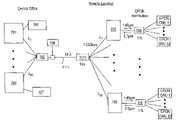
- FIG. 1shows a typical PON 100 for an optical access architecture.
- PON 100includes an optical line terminator (“OLT”) 101 located at a Central Office (“CO”) and a set of optical network units (“ONU”) 103 , or optical network terminals, located at the customer premise.
- OLToptical line terminator
- COCentral Office
- ONUoptical network units
- Each of the ONU 103is connected to the OLT 101 through feeder fiber 102 , e.g., an outside fiber plant, optical power splitter 104 , and individual distribution fibers 105 .
- Feeder fiber 102may transmit optical signals at 125 Megabits per second (“Mbps”), 155 Mbps, 622 Mbps, 1.25 Gigabits per second (“Gbps”), 2.5 Gbps, 10 Gbps, or 40 Gbps, in accordance with standards used for various access platforms.
- Various access platformsincluding various transmission formats, and communication and control protocols, e.g., Ethernet based PON (“EPON”), Broadband PON (“BPON”), Gigabit PON (“GPON”), and ATM based PON (“APON”), has been developed to deliver information, e.g., data, voice, and video, from the Central Office to each of the customer premises.
- Access platformsuse light having a wavelength of 1.49 microns (“um”) to transmit information in downstream 106 direction and light having the wavelength of 1.3 um to transmit information in upstream 107 direction between the Central Office and the customer premises.
- OLT 101contains a high power distributed feedback (“DFB”) laser to produce the light at 1.49 um in downstream 106 direction, which is shared by a plurality, e.g., 16, 32, or more of ONUs 103 .
- DFBdistributed feedback
- the bandwidth of optical signals having the wavelength of 1.49 um and data transmission rate of 1.25 Gbpsis shared between a plurality of ONU 103 using optical power splitter 104 .
- Such configuration of a PONis inefficient because the power supplied to each of the ONUs 103 is reduced at least by the factor of 1/N, wherein N is the amount of ONUs 103 coupled to the power splitter.
- ONU 103typically uses lasers to produce light at 1.3 um within a large optical bandwidth of over 100 nm in upstream 107 direction.
- the wavelength of the light produced by such lasersmay vary with the device distributing the light of the laser, time, temperature, or any other condition.
- OLT 101may service the plurality of ONU 103 through the use of optical power splitter 104 and access platform PON protocols to control the sending and transmission of signal across the shared access facility.
- Datamay be transmitted downstream 106 from OLT 101 to each of ONU 103 , and each ONU 103 processes the data destined to it by matching the address at the access protocol transmission unit header.
- Upstream 107 data from each of the ONU 103 to OLT 101is transmitted according to access control mechanisms and protocols in the OLT 101 , which include a time division multiplexing scheme, in which dedicated transmission time slots are granted to each individual ONU 103 , to avoid data collision.
- transport of information between the Central Office and customer premisesdepends on the type of the access platform used by the Central Office and customer premises.
- each OLT 101 at the Central Officerequires its own feeder fiber 102 to provide data transmission to and from the plurality of ONUs 103 .
- a timing algorithmmay be used in existing access platforms, which limits the distance between the OLT 101 and ONU 103 to 20 km.
- Sharing the same bandwidth between a plurality of ONU 103 in an existing access platformsis not only inefficient, it also can give rise to security issues, because data transmitted from OLT 101 downstream may go to every user. This can produce an additional level of complexity to the data transmission, sometimes requiring scrambling the data code, data encryption, and the like.
- Wavelength division multiplexing (“WDM”) passive optical networks (“PON”) to transport signals having various access platformsare described.
- a WDM PONperforms bi-directional communications, and includes an interface.
- the interfacetransfers one or more signals having a first platform to a WDM-PON data transmission platform at an access point of a network to propagate through a single transmission medium, to one or more remote distribution nodes in between a Central Office and an optical network unit.
- the single transmission mediumcarriers three or more optical channels traveling in both directions.
- FIG. 1shows a typical PON for an optical access architecture.
- FIG. 2shows one embodiment of a WDM PON system, which provides a transport for various platforms.
- FIG. 3shows another embodiment of a system to transport various platforms.
- FIG. 4shows an embodiment of a WDM PON fiber plant transporting an EPON platform.
- FIG. 5shows a block diagram of an embodiment of a line terminal of a WDM PON to transport access platforms.
- FIG. 6shows a block diagram of another embodiment of a WDM PON to transport access platforms.
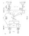
- FIG. 7shows another embodiment of a WDM PON transporting an EPON platform.
- WDM PONswavelength division multiplexing passive optical networks
- DWDMDense WDM
- the WDM PONprovides a virtual point-to-point connection between a Central Office and one or more remote optical network units.
- the WDM PON for performing bi-directional communicationincludes an interface to transfer a set of one or more signals having a first platform to a WDM PON data transmission platform at an access point of a network.
- the signals in the WDM PON transmission platformpropagate through a single transmission medium to one or more remote distribution nodes in between a Central Office and an optical network unit.
- the single transmission mediumcarries three or more optical channels traveling in both directions.
- the optical spacing between the optical channelsis less than 10 nm, in accordance with DWDM transmission scheme.
- the interfaceincludes three or more wavelength locked optical transmitters.
- the access point of a networkmay be the Central Office.
- the WDM-PONfurther includes another interface to transfer the WDM-PON data transmission platform back into the first platform of the set of one or more signals at a distribution point of the network.
- the interfacemaintains a data sequence of the set of one or more signals by examining the data in each signal of the set of one or more signals and data modulating that information onto its own wavelength optical channel transmitted in the WDM-PON.
- the WDM PONincludes a first interface to input a first set of one or more signals having a platform, e.g., an access platform, and output a second set of one or more signals through a single optical transmission medium, e.g., an optical feeder fiber.
- the second set of one or more signalsis configured to comply with a WDM transmission platform/format.
- the second set of one or more signalsmay preserve the sequence of the data of the first set of signals in the first platform.
- the transport of the second set of one or more signals through the single transmission mediumis platform independent.
- the WDM PONmay include a second interface to input the second set of one or more signals from the single optical transmission medium and to output a third set of one or more signals.
- the third set of signalsmay have the platform of the first set of signals.
- the second set of one or more signalsmay include one or more wavelength locked signals generated by one or more wavelength locked transmitters.
- the WDM PON transporting access platformsmay be future proof, because the data rate may be upgraded without changing the outside fiber plant.
- the second set of signals traveling through the single optical transmission mediummay have adjustable data rate that allows increased transmission rate for the WDM PON system that transports access platforms. For example, the data rate of the second set of signals propagating at each WDM wavelength through the single optical feeder fiber may be scaled up over time abolishing the need for adding another optical feeder fiber.
- Using WDM PON to transport various access platformsmay reduce the number of optical fibers in the optical transport layer at least by a factor of 10 resulting in substantial cost savings.
- FIG. 2illustrates an embodiment of system 200 , which provides a transport for various platforms.
- the system 200includes an interface 201 to input set of signals 202 - 206 .
- Interface 201may be an optical line terminal located at a Central Office (“CO”).
- COCentral Office
- set of signals 202 - 206has different platforms, e.g., different data, voice, and video transmission formats, protocols, and standards.
- signal 202is an EPON access platform
- signal 203is a BPON access platform
- signal 204is a GPON access platform
- signal 205supports Synchronous Optical Network or Synchronous Digital Hierarchy (“SONET/SDH”) data transmission platform
- signal 206supports Ethernet standard platform, e.g., Gigabit Ethernet (“GE”) standard to supply an Ethernet switch or a Digital Subscriber Line Access Module (“DSLAM”).
- sets of signals 202 - 206may have the same platform, e.g., EPON access platform.
- at least one of sets of signals 202 - 206may have a wireless platform, e.g. a wireless fidelity (“Wi-Fi”) platform, or Wi-Max platform.
- sets of signals 202 - 206may be multiple tone, digital electronic, analog electronic, and optical sets of signals.
- interface 201outputs one or more sets of signals 207 through an optical transmission medium 208 , e.g., a single optical fiber.
- Each of the set of signals 207has a wavelength ⁇ 1 , ⁇ 2 , ⁇ 3 , ⁇ 4 , or ⁇ 5 , wherein each of the wavelengths ⁇ 1 , ⁇ 2 , ⁇ 3 , ⁇ 4 , or ⁇ 5 is mapped to each of set of signals 202 - 206 .
- the wavelengths ⁇ 1 - ⁇ 5comply with WDM format, e.g., DWDM format, such that the set of signals 207 do not share the same optical bandwidth while propagating through the same optical transmission medium 208 .
- Each of the set of signals 207may preserve a sequence of the data, or protocol in the respective platform of each of set of signals 202 - 206 . That is, each of set of signals 202 - 206 may be transferred bit-by-bit into each of set of signals 207 having wavelengths ⁇ 1 - ⁇ 5 .
- signal 207 having wavelength ⁇ 1may preserve (“maintain”) the sequence of the data, and/or protocol, in the platform of signal 202 ; the signal of wavelength ⁇ 2 may preserve the sequence of the data, and/or protocol, in the platform of signal 203 , the signal of wavelength ⁇ 3 may preserve the sequence of the data, and/or protocol, in the platform of signal 204 , the signal of wavelength ⁇ 4 may preserve the sequence of the data, and/or protocol, in the platform of signal 205 , and the signal of wavelength ⁇ 5 may preserve the sequence of the data, and/or protocol, in the platform of signal 206 .
- Wavelengths ⁇ 1 - ⁇ 5comply with Dense WDM (“DWDM”) scheme, Coarse WDM (“CWDM”) scheme, or a combination thereof.
- DWDMDense WDM
- CWDMCoarse WDM
- the optical spacing between each wavelength channel ⁇ 1 - ⁇ 5is less than 10 nm. More specifically, the optical spacing between wavelengths ⁇ 1 - ⁇ 5 may comply with International Telecommunication Union (“ITU”) grid specification of 25 GHz-200 GHz, or, in wavelength units, from about 0.2 nm to about 1.6 nm.
- the optical spacing between wavelengths ⁇ 1 - ⁇ 5comply with Coarse WDM (“CWDM”) scheme of at least 20 nm.
- wavelengths ⁇ 1 - ⁇ 5may be in the approximate range of 1420 nm to 1650 nm, corresponding to transmission bands of the optical transmission medium 208 .
- an interface 209inputs set of signals 207 from optical transmission medium 208 and outputs set of signals 210 - 214 to deliver the information to various users.
- Interface 209may be at a remote location from the Central Office, at a distance, e.g., 0 to 100 kilometers (“km”), and more specifically, at a distance from around 1 km to around 30 km.
- interface 209may be an optical network unit at a remote location.
- the Set of signals 210 - 214has the platform of a corresponding set of signals 202 - 206 .
- the signal 210may have EPON access platform of signal 202 to deliver the information, e.g., data, voice, and video, in Fiber To The Home (“FTTH”) fiber-optic design architecture.
- the signal 211may have BPON access platform of signal 203 to deliver the information in Multi-Dwelling Units (“MDU”) design architecture.
- the signal 212may have GPON access platform of signal 204 to deliver the information to the Ethernet Switch, which further delivers the information to subscribers through unshielded twisted pair (“UTP”) cables.
- the signal 213may support Ethernet standard of signal 206 to deliver the information to the DSLAM, which further delivers the information through twisted pair cables.
- the signal 214may have a wireless access platform, e.g., a Wi-Fi platform, or Wi-Max platform, and may be sent to a wireless access point.
- Signal 214may contain information provided by signal 205 .
- set of signals 210 - 214may have the platform different from the platform of corresponding set of signals 202 - 206 .
- WDM PONmay provide bi-directional transmission of the set of signals through a single optical transmission medium 208 , as described in further details below with respect to FIGS. 4 and 5 .
- interface 201includes an electrical to optical (E/O), optical-to-electrical-to optical (O/E/O), or optical-to-optical (O/O) converter.
- interface 209includes O/E/O converter, O/O converter, or O/E/O converter, as described in further details below with respect to FIGS. 4 and 5 .
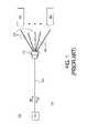
- FIG. 3shows another embodiment of the system 310 to transport various platforms.
- system 310includes Optical Line Terminal (“OLT”) 301 located at the Central Office.
- Set of signals of various communication platforms (“applications”)such as GE (Gigabit Ethernet), SONET, BPON, EPON, and GPON input into the Optical Line Terminal (“OLT”) 301 , as shown in FIG. 3 .
- set of signals at the input of OLT 301may have a Wi-Fi access platform (not shown).
- OLT 301outputs set of signals configured in accordance with WDM scheme, e.g., DWDM scheme, through the single optical fiber 302 , e.g., an outside plant feeder fiber, as described above with respect to FIG.
- WDM schemee.g., DWDM scheme
- system 310further includes an optical multiplexer/demultiplexer 303 to demultiplex WDM set of signals propagating through optical fiber 302 from the Central Office.
- the multiplexer/demultiplexer 303further distributes the respective WDM set of signals with respective preserved sequence of the data, and/or protocols, to respective Optical Network Units (“ONU”) 304 - 309 of system 310 located near the remote customers (or users), e.g., as shown in FIG. 3 .
- ONUOptical Network Units
- ONU 304 - 308 of system 310provide interfaces to Ethernet switches, DSLAM, BPON, EPON, GPON, Wi-Fi, or WiMax access platforms to deliver the information through Fiber-to-the-Curb (“FTTC”), Fiber-to-the-Building (“FTTB”), Fiber-to-the-Premise (“FTTP”), MDU, or any other access design architectures, as shown in FIG. 3 .
- FTTCFiber-to-the-Curb
- FTTBFiber-to-the-Building
- FTTPFiber-to-the-Premise
- MDUor any other access design architectures
- system 300transparently transports the applications to respective customers providing virtual point-to-point connection between a Central Office and a customer location.
- the system 300is a future proof system, because it may be upgraded without changing an outside fiber plant.
- the data transmission rate at each wavelength through the single optical fiber 302may be scaled up, or protocol may be changed in the future without a need of changing the outside fiber plant, e.g., adding another optical fiber, or a MUX/DMUX.
- the data transmission ratemay be increased from 100 Mbps/wavelength to 10 Gbps/wavelength without adding another optical fiber.
- the system 300is transparent for any access application, such that an inventory of matching access components for different applications is no longer needed.
- FIG. 4shows an embodiment of WDM PON fiber plant 401 transporting an EPON platform.
- WDM PON fiber plant 401e.g. DWDM PON fiber plant
- WDM PON fiber plant 401includes 1 to M converters 402 , wherein M is an integer number, e.g., 16.
- Each of converters 402inputs EPON set of signals from each of 1 to M EPON Optical Line Terminals (“EPON OLT”) 403 and outputs WDM set of signals, e.g., DWDM set of signals.
- EPON OLT 403are optical signals having a wavelength of 1.49 um in compliance with EPON access platform for downstream direction from a Central Office to customer premises.
- WDM PON 401further includes a multiplexer/demultiplexer (“MUX/DMUX”) 404 coupled to converters 402 to multiplex WDM set of signals for transmission through a single optical fiber 405 .
- MUX/DMUX 404includes Arrayed Waveguide Grating Multiplexers and Demultiplexers (“AWG MU/DMUX”) known to one of ordinary skill in the art of telecommunications.
- MUX/DMUX 404includes thin film dielectric filters known in the art of telecommunications.
- converter 402is an electrical to optical (E/O), optical-to-electrical-to-optical (O/E/O), or optical-to-optical (O/O) converter.
- fiber plant 401further includes a MUX/DMUX 406 , which demultiplexes WDM set of signals from optical fiber 405 , such that a WDM signal having a respective wavelength ⁇ m is sent to a respective converter 407 .
- MUX/DMUX 406may be located at a remote location from a Central Office.
- MUX/DMUX 406includes AWG MUX/DMUX, thin film dielectric filters, or a combination thereof.
- AWG MUX/DMUX and thin film dielectric filtersare known to one of ordinary skill in the art of telecommunications.
- converter 407is an O/E/O converter, or O/O converter. As shown in FIG.
- each of converters 407inputs a WDM signal at a WDM wavelength and outputs an optical EPON signal, which is sent to a 1:N power splitter 408 for access platform distribution between customer premises, e.g., between EPON ONUs 1 to N, wherein N may be any integer number, e.g., 32.
- the WDM-PON optical transportlooks transparent to EPON OLTs 403 and to EPON ONUs, as shown in FIG. 4 .
- the fiber plant 401is used for transport in opposite directions, downstream and upstream, as shown in FIG. 4 .
- the optical wavelength used in an EPON systemis 1.49 microns for downstream traffic and 1.3 microns for upstream traffic.
- EPON wavelengthsare converted to different WDM wavelengths sent over the WDM-PON fiber plant 401 since it uses a much denser wavelength spacing plan so to allow many wavelengths to be transported over a single optical feeder fiber. That is, overlaying EPON on to the WDM PON transmission platform, e.g., WDM PON provides increased data transmission bandwidth from the Central Office out to the remote sites over just a single optical fiber 405 .
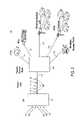
- FIG. 5shows a block diagram of an embodiment of a line terminal of a WDMPON, e.g., DWDM PON, to transport access platforms.
- line terminal 510 located at a Central Officeincludes one or more receivers 501 to receive an optical signal in downstream direction 505 from one or more access platform optical line terminals (“AP OLTs”) 502 and one or more receivers 511 to receive an optical signal in upstream direction 506 from remote nodes.
- AP OLTs 502may be an EPON, GPON, BPON, or any other access platform optical line terminals.
- AP OLTs 502may produce optical signals at a data transmission rate of 125 Mbps, 155 Mbps, 622 Mbps, 1.25 Gbps, 2.5 Gbps, 10 Gbps, or 40 Gbps, which is determined by standards, formats, and protocols of respective access platforms.
- an optical signal from AP OLT 502 in a downstream direction 505has a wavelength of 1.49 um and an optical signal in upstream direction 506 has a wavelength of 1.3 um.
- receivers 501 and 511may include a bit error correction scheme to correct for error bits of incoming set of signals. As shown in FIG.
- one or more receivers 501output electrical signals to drive one or more transmitters 503 and one or more receivers 511 output electrical signals to drive one or more transmitters 512 .
- Receivers 501examine the data in set of signals from AP OLT 501 and produce set of electrical signals that maintain a data sequence, or protocols, of each of the set of signals from AP OLT 501 .
- Transmitters 503 driven by the receivers 501generate optical signals having wavelengths in compliance with a WDM transmission scheme, as described above with respect to FIG. 2 . That is, each of the transmitters produces a modulated optical signal having a wavelength in a WDM-PON transmission platform. The wavelength of the modulated optical signal is mapped to the respective AP OLT 501 .
- Optical signals generated by transmitters 503maintain the data sequence, and/or protocol, of the set of signals from AP OLT 501 .
- Transmitters 503include at least one wavelength locked light source to produce an optical signal having a locked wavelength, such that the wavelength of the optical signal is steady and does not wander with time, temperature, or any other condition.
- a wavelength locked light sourcemay be a wavelength locked Fabry-Perot laser diode, a reflective semiconductor optical amplifier (RSOA), or other similar optical light source configured to operate below a lasing threshold when being suppressed by an injected spectral light signal.
- the wavelength locked light sourcemay also be a reflective modulator, e.g., Lithium Niobate (LiNbO3) modulator.
- transmitters 503include a wavelength specific light source, e.g., DFB laser, Distributed Bragg Reflector (“DBR”) laser, tunable laser, or similar optical transmitter configured to transmit light having a specific wavelength.
- DFB laserDistributed Bragg
- one or more light sources of transmitters 503may include directly modulated or externally modulated light sources.
- the externally modulated light sourcemay include Lithium Niobate modulator, electro-absorption modulator, or any combination thereof, to modulate the light in accordance with the data transmission rate, e.g., 125 Mbps, 155 Mbps, 622 Mbps, 1.25 Gbps, 2.5 Gbps, 10 Gbps, and 40 Gbps.
- the line terminal 510further includes one or more band splitting filters 504 to optically separate the set of signals traveling in downstream direction 505 from set of signals traveling in upstream direction 506 .
- the line terminal 510includes a MUX/DMUX 507 to multiplex optical set of signals traveling in downstream direction 505 and demultiplex the optical set of signals traveling in upstream direction 506 .
- MUX/DMUX 507may include circulators to separate optical signals traveling in downstream direction 505 and upstream direction 506 .
- the optical signals produced by transmitters 503are multiplexed by MUX/DMUX 507 to transmit through a single optical fiber 508 .
- Data transmission rate for the optical signals traveling along the single optical fiber 508may be changed without the need of changing the number of fibers for outside fiber plant.
- Another AP OLT 502may be added to transport information to other remote modes through the same single optical fiber 508 .
- MUX/DMUX 507is an AWG with a free spectral range (“FSR”) to multiplex/demultiplex light having wavelengths in the approximate range of 1420 nm to 1650 nm.
- FSRfree spectral range
- MUX/DMUX 507may have the spacing between optical channels less than 10 nm.
- MUX/DMUX 507is an arrayed waveguide MUX/DMUX having the optical spacing between adjacent optical channels in the range of 25 GHz-200 GHz.
- Transmitters 512 driven by receivers 511produce optical signals, which are delivered to respective AP OLTs 502 .
- transmitters 512produce optical signals having a wavelength of 1.3 nm in compliance with access platform standards for an upstream traffic.
- transmitters 512include low power Fabry-Perot lasers known to one of ordinary skill in the art.
- FIG. 6shows a block diagram of another embodiment of a WDM PON to transport access platforms.
- the WDM PON 600e.g., DWDM PON, may include an interface 630 located at a Central Office, a remote node 640 , and a plurality of end user locations.
- the interface 630contains one or more optical-to-electrical (O/E) converters 651 - 653 to receive and examine data of set of one or more signals having an access platform.
- the access platform of the set of one or more signalsmay be an EPON, BPON, SONET, DSL, GE, and WiMax platform.
- Converters 651 - 653may transfer bit-by-bit the received data of set of one or more signals into electrical set of signals to drive one or more transmitters 601 - 603 .
- the interface 630may contain one or more optical receivers 604 - 606 , one or more band splitting filters 607 - 609 , a 1 ⁇ N multiplexer/demultiplexer 612 , a broadband light source 614 , and an optional temperature controller 610 .
- transmitters 601 - 603may include a wavelength specific light source, e.g., a distributed feedback (“DFB”) laser. Each wavelength-specific light source may have an associated modulator and gain pump.
- DFBdistributed feedback
- a first transmitter 601may be a distributed feedback laser coupled to an associated modulator 640 and a gain pump 641 .
- the gain pump 641 and modulator 640which is driven by electrical signals from converter 651 , may each supply the electrical current to the active region of the light source.
- Each remote locationmay contain an optical network unit (ONU) 631 - 633 .
- each ONU 631 - 633includes respective optical receivers 620 - 622 , and transmitters 623 - 625 .
- Each ONU 631 - 632provides an interface between a set of signals having a WDM platform and a set of signals having an access platform, as described above with respect to FIGS. 2-5 .
- an access platformmay be may be an EPON, BPON, SONET, DSL, GE, or WiMax platform of the respective signals at the input of the interface 630 at the Central Office.
- transmitters 623 - 625include a wavelength-locked light source.
- Transmitters 623 - 645may have an associated modulator and gain pump.
- transmitter 623is coupled to modulator 143 .
- the first remote locationmay contain a first ONU 631 with a first optical receiver 620 , a first wavelength-locked light source 623 , such as a Fabry-Perot laser diode, a first band splitting filter 617 , a first modulator 643 , and a first gain pump 644 .
- the first band splitting filter 617is configured to direct wavelengths in a first wavelength band from a transmitter in the interface 630 to the optical receiver 620 .
- the first band splitting filter 617is also configured to direct wavelengths in a different wavelength band from the broadband light source 614 into the first wavelength-locked light source 623 .
- a WDM Optical Time Domain Reflectometer (“OTDR”) coupled to the optical fiber 650may be used to optically diagnose the infrastructure of WDM PON 600 .
- the Optical Time Domain Reflectometermay be used to detect faults such as breaks in the optical cables, such as the optical cables going between a remote node and the central office as well as the optical cables going between a remote node and each subscriber's location.
- transmitters 601 - 603 in interface 630may be used for downstream communications B in the WDM PON through optical fiber 650 to supply data to subscribers at a first data rate.
- the wavelength-locked light sources 623 - 625 in the remote locationsmay transmit upstream communications A in the WDM PON through optical fiber 650 to supply data signals at a second data rate back to the optical receivers 604 - 606 in the interface 630 .
- the first data ratemay be asymmetric or in other words at a different bit rate compared to the second data rate.
- the first data rate for downstream communications Bsuch as 1 gigabyte per second, may be greater than the second data rate for upstream communications, such as 100 megabytes per second.
- the pump 641supplies a bias current to the transmitter 601 .
- the bias currentcooperates with a signal provided by the data modulator 640 to generate the downstream data signal from the transmitter 601 .
- the pump 644supplies a bias current to the wavelength-locked light source 623 .
- the bias currentcooperates with a signal provided by the second data modulator 643 to generate the upstream data signal from the wavelength-locked light source 623 .
- the second 1 ⁇ N multiplexer/demultiplexer 616 at the remote node 640may be used for both routing the wavelengths between the subscribers' locations and the interface 630 at the Central Office as well as supplying a separate spectral slice from a broadband light source 614 to wavelength lock an output wavelength of each wavelength-locked light sources 623 - 625 .
- the broadband light source 614supply an optical signal containing a first band of wavelengths, such as the C-band (1530 nm ⁇ 1560 nm), to the second 1 ⁇ N multiplexer/demultiplexer 616 .
- a first band of wavelengthssuch as the C-band (1530 nm ⁇ 1560 nm)
- the second 1 ⁇ N multiplexer/demultiplexer 616 in the remote locationspectrally slices this broadband light signal from the broadband light source 614 .
- a first port of the 1 ⁇ N multiplexer/demultiplexer 616couples via an optical cable to the ONU 631 .
- the 1 ⁇ N multiplexer/demultiplexer 616wavelength locks the output wavelength of the first wavelength-locked light source 623 by injecting a spectral slice into the wavelength-locked light source 623 .
- the wavelength-locked light source 623is operated below the lasing threshold when being suppressed by the first injected spectral slice.
- the wavelength-locked light source 623locks its output wavelength to approximately the wavelength of the injected spectral slice.
- Each port of the 1 ⁇ N multiplexer/demultiplexer 616generates a spectral slice of the broadband light signal with a different wavelength within the wavelength range of the broadband light signal.
- Each converter 620 - 623 in the remote locationsis configured, via its band splitting filters 617 - 619 , to receive a wavelength signal corresponding to the associated transmitters 601 - 603 in the interface 630 at the Central Office.
- Each of optical receivers 604 - 606 in the interface 630is configured, via its band splitting filters 607 - 609 , to receive a wavelength signal corresponding to the associated wavelength-locked light source 623 - 625 in a remote location.
- the wavelength-locked light sourcemay be a Fabry-Perot laser diode, a Reflective Semiconductor Optical Amplifier (RSOA), or other similar optical transmitter configured to operate below a lasing threshold when being suppressed by an injected spectral light signal.
- the wavelength-specific light sourcemay be a Distributed FeedBack (DFB) laser, DBR laser (Distributed Bragg Reflector) laser, tunable external cavity laser or similar optical transmitter configured to transmit a repeatable specific wavelength with enough power to transmit at a high data speed.
- DFBDistributed FeedBack
- DBR laserDistributed Bragg Reflector
- a temperature controllersuch as the temperature controller 145 at the wavelength-locked light source 623 , may alter the operating temperature of the wavelength-locked light source to fine tune its resonant wavelength.
- a temperature controllersuch as the temperature controller 110 at interface 630 , may alter the operating temperature of the wavelength-specific light source to fine tune its resonant wavelength.
- the modulatormay be a direct modulator or an external modulator.
- the direct modulatormay cooperate with a gain pump to directly data modulate the wavelength-specific light source.
- the direct modulationalters a gain of its associated wavelength-specific light source or wavelength-locked light source.
- the external modulatorsuch as LiNb03 (Lithium Niobate) or EA (electro-absorption) modulators, data modulates its associated wavelength-specific light source or wavelength-locked light source.
- the external modulatormodulates by passing or blocking the light generated from the light source in a separate stage from where the lasing action occurs in the light source.
- the gain pumpmay also control the bias current supplied to its associated optical transmitter to alter the resonant wavelength of its optical transmitter.
- FTTCFiber To The Curb
- High speed wavelength-specific light sourcesmay be used to send higher speed data in one direction.
- Wavelength-locked light sourcesmay be used for data transfer in the reverse direction at a slower speed.
- the ratio between the high speed data rates, such as 10 Gbps, and the slower speed data rates, such as 155 Mbps,can be greater than fifty to one.
- the hybrid WDM-PONretains the advantage of having identically manufactured ONUs with low cost transmitters in the field (i.e. installed in subscriber'locations).
- the consumable ONUsmakes them easier for maintenance, service and repair.
- the wavelength-specific light sourcesare located in the Central Office interface where maintenance is easier and there is less chance of confusing which wavelength-specific light source is connected to each port of the first 1 ⁇ N multiplexer/demultiplexer.
- the wavelength-specific light sources at the interfacecan be directly modulated DFB lasers.
- the hybrid WDM PONcan use 16 different DFB lasers separated by 200 GHz (or 1.6 nanometers (nm) in wavelength). The total range of the down stream bandwidth is approximately 26 nm, i.e. 16 channels X 1.6 nm/channel.
- Each DFB lasercan be stabilized or locked to the appropriate channel by using a thermo-electric coder (TEC) to temperature control the DFB chip temperature. Since the wavelength/temperature sensitivity for a DFB laser may be 0.1 nm/degree Centigrade (° C.), temperature stability merely should be maintained within a few degrees since the channel spacing is 1.6 nm.
- the example DFB laserscan be directly modulated above 1.25 Gbps to transfer a high speed downstream data signal. Higher and lower data rates can also be used.
- the downstream wavelength band for the optical transmitters in the interfacemay be in a first wavelength band such as the L-band (1570 nm ⁇ 1600 nm), O-band ( ⁇ 1310 nm), S-band (1450 nm), etc.
- the upstream wavelength band for the optical transmitters in the end user's locationsmay be in a second wavelength band, such as the C-band, different than the first wavelength band.
- the broadband light sourcesuch as an Erbium Doped Fiber Amplifier source, may generate a broadband light signal encompassing the C-band.
- the second 1 ⁇ N multiplexer/demultiplexerthen spectrally slices up in the incoming C-band light signal to send each end user location its own discrete wavelength.
- another backup feeder optical fibermay be inserted between interface 630 and remote node 640 to provide a backup route for the data transmission if the feeder optical fiber 650 breaks.
- the backup feeder optical fibermay be physically routed in a separate location and in a different bundle of fibers then the feeder optical fiber 650 .
- the redundancymay be automatically switched into operation with a switch.
- Various devicesmay be used to fine tune the resonant wavelength of the optical transmitters in the interface and end user locations such as the above mentioned temperature controllers, MEMS (Micro Electro-Mechanical Structures), dielectric optical band pass filters for feedback, Fiber Bragg Gratings (FBG) using strain tuning and other techniques.
- MEMSMicro Electro-Mechanical Structures
- FBGFiber Bragg Gratings
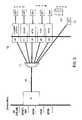
- FIG. 7shows another embodiment of WDM PON 700 , e.g., DWDM PON, transporting an EPON platform.
- WDM PON 700includes 1 to M EPON Optical Line Terminal (“EPON OLT”) cards 701 , wherein M is an integer number, e.g., 16.
- EPON OLT cards 701has a bidirectional WDM PON optical transceiver, which contains an optical receiver and at least one wavelength locked light source, as described above with respect to FIGS. 5 and 6 .
- EPON OLT cards 701are located at a Central Office and are compatible with the EPON access interface in the Central Office.
- Each of EPON OLT cards 701outputs WDM set of signals having a wavelength ⁇ m, wherein m is an integer number corresponding to each of the respective EPON OLT cards 701 .
- EPON OLT card 701while being compatible with EPON access interface in the Central Office, eliminates at least one of the interface conversions, e.g., at least one O-E-O conversion, between EPON access platform and WDM platform. As such, EPON OLT card 701 is more cost effective relative to existing EPON OLT cards.
- EPON OLT card 701may simply replace existing EPON OLT cards without affecting functions of the existing EPON OLTs, e.g., compatibility with the EPON access interface in the Central Office.
- WDM PON 700further includes a multiplexer/demultiplexer (“MUX/DMUX”) 702 coupled to EPON OLT cards 701 to multiplex WDM set of signals for transmission through an optical fiber 703 .
- MUX/DMUX 702includes Arrayed Waveguide Grating Multiplexers and Demultiplexers (“AWG MUX/DMUX”) known to one of ordinary skill in the art of telecommunications.
- MUX/DMUX 702includes thin film dielectric filters known in the art of telecommunications. As shown in FIG.
- a broadband light source 708supplies a separate spectral slice of light through the optical fiber 703 to lock an output wavelength of at least one wavelength-locked light source of WDM PON to EPON O-E-O converter 705 , as described above with respect to FIG. 6 .
- WDM PON 700further includes a MUX/DMUX 704 , which demultiplexes WDM set of signals from optical fiber 703 , such that a WDM signal having a respective wavelength ⁇ m is sent to a respective WDM PON to EPON O-E-O converter 705 .
- MUX/DMUX 704may be located at a remote location from a Central Office.
- MUX/DMUX 704includes AWG MUX/DMUX, thin film dielectric filters, or a combination thereof.
- AWG MUX/DMUX and thin film dielectric filtersare known to one of ordinary skill in the art of telecommunications. As shown in FIG.
- each of converters 705inputs a WDM signal at a WDM wavelength and outputs an optical EPON signal, which is sent to a 1:N power splitter 706 for access platform distribution between customer premises, e.g., between EPON ONUs 1 to N, wherein N may be any integer number, e.g., 32.
- the WDM PON 700is used to transport data in opposite directions, downstream and upstream, as described above with respect to FIGS. 4-6 .
- WDM PON 700includes one or more monitors 707 to provide diagnostics of the WDM PON 700 .
- a WDM Optical Time Domain Reflectometer (“OTDR”)may be used to optically diagnose the infrastructure of WDM PON 700 .
- one or monitors 707monitor the status of the one or more OEO converters associated with the EPON OLT cards 701 . Monitors are coupled to EPON OLT cards 701 , as shown in FIG. 7 , to provide a remote diagnostics of the OEO converters located at the Central Office and at a remote location.
- monitors 707may diagnose failure of one or more OEO converters and provide such information to the network management system (not shown), which controls a proper operation of the WDM PON 700 .
- Monitors 707provide remote diagnostics without disturbing the transparency of the data conversion.
- the remote diagnostics of the OEO convertersmay be realized by adding an additional modulation signal (“monitoring signal”) onto the data signal.
- the data transmission rates for remote diagnosticsare substantially smaller than the data transmission rates for the data optical signal, so the additional perturbation of the data optical signal, which may be caused by an additional modulation signal, is minimized.
- the amplitude of the monitoring set of signalsmay be substantially smaller than the amplitude of the data set of signals.
- the monitoring signal provided to monitors 707is outside the bandwidth used for the data transmission over the WDM PON 700 .
- the small monitoring signal provided to monitors 707may be a low-frequency signal, e.g., below about 10 KHz.
- the small monitoring signal provided to monitors 707may be a high-frequency signal, above the frequency bandwidth used for data transmission.
- the monitoring signal provided to monitors 707may have a wavelength, which is different from the wavelengths of the signals used to data transmission. For example, because additional wavelength bands exist in the WDM PON architecture, the remote monitoring can be performed over an additional wavelength.
Landscapes
- Engineering & Computer Science (AREA)
- Computer Networks & Wireless Communication (AREA)
- Signal Processing (AREA)
- Optical Communication System (AREA)
- Small-Scale Networks (AREA)
Abstract
Description
Claims (26)
Priority Applications (2)
| Application Number | Priority Date | Filing Date | Title |
|---|---|---|---|
| US11/187,993US7627246B2 (en) | 2005-07-22 | 2005-07-22 | Wavelength division multiplexing passive optical networks to transport access platforms |
| PCT/US2006/028434WO2007014055A1 (en) | 2005-07-22 | 2006-07-20 | Wavelength division multiplexing passive optical networks to transport different access formats |
Applications Claiming Priority (1)
| Application Number | Priority Date | Filing Date | Title |
|---|---|---|---|
| US11/187,993US7627246B2 (en) | 2005-07-22 | 2005-07-22 | Wavelength division multiplexing passive optical networks to transport access platforms |
Publications (2)
| Publication Number | Publication Date |
|---|---|
| US20070019956A1 US20070019956A1 (en) | 2007-01-25 |
| US7627246B2true US7627246B2 (en) | 2009-12-01 |
Family
ID=37199121
Family Applications (1)
| Application Number | Title | Priority Date | Filing Date |
|---|---|---|---|
| US11/187,993Expired - Fee RelatedUS7627246B2 (en) | 2005-07-22 | 2005-07-22 | Wavelength division multiplexing passive optical networks to transport access platforms |
Country Status (2)
| Country | Link |
|---|---|
| US (1) | US7627246B2 (en) |
| WO (1) | WO2007014055A1 (en) |
Cited By (16)
| Publication number | Priority date | Publication date | Assignee | Title |
|---|---|---|---|---|
| US20080019691A1 (en)* | 2004-07-01 | 2008-01-24 | Philippe Guignard | Multiservice Private Network And Interface Modules For Transporting, On Such A Network, Data In Different Formats |
| US20090154924A1 (en)* | 2007-12-14 | 2009-06-18 | Yanming Liu | Passive optical network with wavelength division multiplexing |
| US20100070823A1 (en)* | 2007-05-26 | 2010-03-18 | Dongyu Geng | Method and device for information block coding and synchronization detecting |
| US20100196010A1 (en)* | 2005-12-09 | 2010-08-05 | Furukawa Electric Co., Ltd. | Optical transmission system |
| US20110026922A1 (en)* | 2009-07-31 | 2011-02-03 | Yusuke Ota | Optical fiber network with improved fiber utilization |
| US20120033972A1 (en)* | 2010-08-06 | 2012-02-09 | Futurewei Technologies, Inc. | Hybrid Orthogonal Frequency Division Multiplexing Time Domain Multiplexing Passive Optical Network |
| US20120093509A1 (en)* | 2009-06-16 | 2012-04-19 | Hitachi, Ltd. | Optical multiplexing terminating device, wave-length multiplexing passive optical network system, and downstream wave-length transmission method |
| US8180223B2 (en)* | 2006-02-03 | 2012-05-15 | Fujitsu Limited | System and method for extending reach in a passive optical network |
| US8290370B2 (en) | 2005-09-20 | 2012-10-16 | Korea Advanced Institute Of Science And Technology | Wavelength division multiplexing passive optical network for providing both of broadcasting service and communication service and central office used thereof |
| US8326151B2 (en) | 1999-12-21 | 2012-12-04 | Korea Advanced Institute Of Science And Technology | Low-cost WDM source with an incoherent light injected Fabry-Perot laser diode |
| US20130223840A1 (en)* | 2012-02-28 | 2013-08-29 | Donald C.D. Chang | Resource Allocation in PON Networks via Wave-front Multiplexing and De-multiplexing |
| US8571410B2 (en) | 2006-10-11 | 2013-10-29 | Novera Optics, Inc. | Mutual wavelength locking in WDM-PONS |
| US8861963B2 (en) | 2003-05-30 | 2014-10-14 | Novera Optics, Inc. | Shared high-intensity broadband light source for a wavelength-division multiple access passive optical network |
| TWI472171B (en)* | 2012-09-26 | 2015-02-01 | Chunghwa Telecom Co Ltd | Detection Method and Device for Lightning Mode Modulus FP Laser Spurious Wave Multiplication Passive Optical Network Loop Break |
| US9130671B2 (en)* | 2005-09-07 | 2015-09-08 | Korea Advanced Institute Of Science And Technology | Apparatus for monitoring failure positions in wavelength division multiplexing-passive optical networks and wavelength division multiplexing-passive optical network systems having the apparatus |
| EP3285421A1 (en) | 2016-08-19 | 2018-02-21 | Swisscom AG | Access distribution point and hybrid network architecture |
Families Citing this family (51)
| Publication number | Priority date | Publication date | Assignee | Title |
|---|---|---|---|---|
| JP2007053647A (en)* | 2005-08-19 | 2007-03-01 | Hitachi Communication Technologies Ltd | Optical termination device and transmission system |
| US7831146B2 (en)* | 2005-09-15 | 2010-11-09 | Mazed Mohammad A | Time and wavelength-shifted dynamic bidirectional system |
| US7643753B2 (en)* | 2005-09-29 | 2010-01-05 | Broadlight Ltd. | Enhanced passive optical network (PON) processor |
| US9059946B2 (en)* | 2005-09-29 | 2015-06-16 | Broadcom Corporation | Passive optical network (PON) packet processor |
| US8600238B2 (en)* | 2005-11-01 | 2013-12-03 | Technology Advancement Group, Inc. | Method and system for bi-directional communication over a single optical fiber |
| US7983277B1 (en)* | 2005-11-30 | 2011-07-19 | Sprint Communications Company L.P. | System and method for creating a secure connection over an MPLS network |
| WO2007062606A1 (en)* | 2005-12-02 | 2007-06-07 | Huawei Technologies Co., Ltd. | A method and system for interconnecting the broadband wireless access network with the optical access broadband network |
| US8098990B2 (en)* | 2006-09-12 | 2012-01-17 | Nec Laboratories America, Inc. | System and method for providing wireless over a passive optical network (PON) |
| US20080144544A1 (en)* | 2006-12-19 | 2008-06-19 | Sam Shi | Method and system of combining signals in bpl communications |
| US8059962B2 (en)* | 2007-05-30 | 2011-11-15 | Futurewei Technologies, Inc. | Interleaving for 10G GPON |
| US20110055875A1 (en)* | 2007-06-22 | 2011-03-03 | Clariton Networks, Ltd. | Method and apparatus for providing wimax over catv, dbs, pon infrastructure |
| US9300425B2 (en)* | 2007-06-29 | 2016-03-29 | Alcatel Lucent | DWDM hybrid PON LT configuration |
| CN101755404A (en)* | 2007-07-18 | 2010-06-23 | 三菱电机株式会社 | Point-to-multipoint optical communication system |
| CN101114885B (en)* | 2007-09-05 | 2011-07-27 | 华中科技大学 | Wavelength-division and time division multiplex mixing passive optical network system, terminal and signal transmission method |
| WO2009105281A2 (en)* | 2008-02-22 | 2009-08-27 | Opvista Incorporated | Spectrally efficient parallel optical wdm channels for long-haul man and wan optical networks |
| EP2274595B1 (en)* | 2008-05-09 | 2017-11-15 | AFL Telecommunications LLC | Optical time-domain reflectometer |
| JP2010010986A (en)* | 2008-06-26 | 2010-01-14 | Fujikura Ltd | Optical transmission system using four-wave mixing |
| US7933285B2 (en)* | 2008-10-24 | 2011-04-26 | At&T Intellectual Property I, L.P. | Distributed digital subscriber line access multiplexers to increase bandwidth in access networks |
| SE534444C2 (en)* | 2008-10-28 | 2011-08-23 | Syntune Ab | Communication system comprising a tunable laser. |
| US8275262B2 (en) | 2008-11-10 | 2012-09-25 | At&T Intellectual Property I, L.P. | Methods and apparatus to deploy fiber optic based access networks |
| US20100129077A1 (en)* | 2008-11-24 | 2010-05-27 | Nortel Networks Limited | Techniques for implementing a dual array waveguide filter for a wavelength division multiplexed passive optical network |
| EP2452452A1 (en)* | 2009-07-06 | 2012-05-16 | Telefonaktiebolaget L M Ericsson (PUBL) | Improvements in reflective optical networks |
| US20110026930A1 (en)* | 2009-07-29 | 2011-02-03 | Zhi Cui | Methods and apparatus to upgrade communication services in subscriber distribution areas |
| JP5402556B2 (en)* | 2009-11-19 | 2014-01-29 | 富士通株式会社 | Data transmission system, terminal station apparatus, and data transmission method |
| US20110135301A1 (en) | 2009-12-08 | 2011-06-09 | Vello Systems, Inc. | Wavelocker for Improving Laser Wavelength Accuracy in WDM Networks |
| US10341038B2 (en) | 2010-12-14 | 2019-07-02 | Arris Enterprises Llc | Multiplex conversion for a passive optical network |
| US20130089338A1 (en)* | 2011-10-10 | 2013-04-11 | Rad Data Communications Ltd. | Communication network |
| US9154851B2 (en) | 2011-11-10 | 2015-10-06 | Arris Technology, Inc. | Tunable RF return path filter with automatic channel plan detection |
| US8923672B2 (en)* | 2011-11-10 | 2014-12-30 | Alcatel Lucent | Wavelength router for a passive optical network |
| US10110307B2 (en) | 2012-03-02 | 2018-10-23 | Corning Optical Communications LLC | Optical network units (ONUs) for high bandwidth connectivity, and related components and methods |
| WO2013192354A2 (en) | 2012-06-19 | 2013-12-27 | Adtran, Inc. | Optical time domain reflectometer systems and methods using wideband optical signals for suppressing beat noise |
| EP2775733A1 (en)* | 2013-03-05 | 2014-09-10 | British Telecommunications public limited company | Communications network |
| DE102013011983B4 (en) | 2013-07-18 | 2023-12-07 | Drägerwerk AG & Co. KGaA | Medical measuring device, ventilation device and method for operating a medical measuring device or for operating a ventilation device |
| WO2016030880A2 (en)* | 2014-08-25 | 2016-03-03 | Corning Optical Communications Wireless Ltd. | Supporting an add-on remote unit (ru) in an optical fiber-based distributed antenna system (das) over an existing optical fiber communications medium using radio frequency (rf) multiplexing |
| EP2999151B1 (en)* | 2014-09-19 | 2019-06-19 | ADVA Optical Networking SE | Method and communication control device for establishing a communication channel in a communication network |
| US9768585B2 (en) | 2015-03-18 | 2017-09-19 | Applied Optoelectronics, Inc. | Tunable laser including parallel lasing cavities with a common output |
| US9787400B2 (en)* | 2015-04-08 | 2017-10-10 | Corning Optical Communications LLC | Fiber-wireless system and methods for simplified and flexible FTTX deployment and installation |
| US10735838B2 (en) | 2016-11-14 | 2020-08-04 | Corning Optical Communications LLC | Transparent wireless bridges for optical fiber-wireless networks and related methods and systems |
| US10205552B2 (en)* | 2017-01-20 | 2019-02-12 | Cox Communications, Inc. | Optical communications module link, systems, and methods |
| US11502770B2 (en) | 2017-01-20 | 2022-11-15 | Cox Communications, Inc. | Optical communications module link extender, and related systems and methods |
| US10516922B2 (en)* | 2017-01-20 | 2019-12-24 | Cox Communications, Inc. | Coherent gigabit ethernet and passive optical network coexistence in optical communications module link extender related systems and methods |
| GB2578269A (en)* | 2018-03-28 | 2020-05-06 | British Telecomm | Network |
| US10993003B2 (en) | 2019-02-05 | 2021-04-27 | Cox Communications, Inc. | Forty channel optical communications module link extender related systems and methods |
| US10999658B2 (en) | 2019-09-12 | 2021-05-04 | Cox Communications, Inc. | Optical communications module link extender backhaul systems and methods |
| US11317177B2 (en) | 2020-03-10 | 2022-04-26 | Cox Communications, Inc. | Optical communications module link extender, and related systems and methods |
| US11271670B1 (en) | 2020-11-17 | 2022-03-08 | Cox Communications, Inc. | C and L band optical communications module link extender, and related systems and methods |
| US11146350B1 (en) | 2020-11-17 | 2021-10-12 | Cox Communications, Inc. | C and L band optical communications module link extender, and related systems and methods |
| US12199743B2 (en) | 2021-02-12 | 2025-01-14 | Cox Communications, Inc. | Optical communications module link extender including ethernet and PON amplification |
| US11323788B1 (en) | 2021-02-12 | 2022-05-03 | Cox Communications, Inc. | Amplification module |
| US11689287B2 (en) | 2021-02-12 | 2023-06-27 | Cox Communications, Inc. | Optical communications module link extender including ethernet and PON amplification |
| US11523193B2 (en) | 2021-02-12 | 2022-12-06 | Cox Communications, Inc. | Optical communications module link extender including ethernet and PON amplification |
Citations (11)
| Publication number | Priority date | Publication date | Assignee | Title |
|---|---|---|---|---|
| DE4226838A1 (en) | 1992-08-13 | 1994-02-17 | Sel Alcatel Ag | Optical broadband information transmission system for communications - transmits range of TV signals via multiplexing central station over optical line to subscriber units |
| US20020063924A1 (en)* | 2000-03-02 | 2002-05-30 | Kimbrough Mahlon D. | Fiber to the home (FTTH) multimedia access system with reflection PON |
| EP1388963A2 (en) | 2002-08-06 | 2004-02-11 | Choi, Jun-Kook | Wavelength division multiplexing passive optical network system |
| EP1507351A2 (en) | 2003-08-12 | 2005-02-16 | Samsung Electronics Co., Ltd. | Bi-directional wavelength division multiplexing system |
| US20050047785A1 (en)* | 2003-09-01 | 2005-03-03 | Hwang Seong-Taek | Bi-directional wavelength division multiplexing passive optical network and method for allocating wavelength band |
| US20050123300A1 (en)* | 2003-10-18 | 2005-06-09 | Kim Byoung W. | WDM-PON system based on wavelength-tunable external cavity laser light source |
| US20050129402A1 (en)* | 2003-10-21 | 2005-06-16 | Kim Byoung W. | WDM-PON system with optical wavelength alignment function |
| WO2005076942A2 (en) | 2004-02-06 | 2005-08-25 | Utstarcom, Inc. | System and apparatus for a carrier class wdm pon accommodating multiple services or protocols |
| US20060275037A1 (en)* | 2005-06-02 | 2006-12-07 | Evans Alan F | Methods and apparatus for multiple signal amplification |
| US20070165688A1 (en)* | 2003-05-29 | 2007-07-19 | Chang-Hee Lee | Light source cable of lasing that is wavelength locked by an injected light signal |
| US7440696B2 (en)* | 2002-08-21 | 2008-10-21 | Nec Corporation | Data multiplexing network, wavelength multiplexer, and data multiplexing transmission method |
- 2005
- 2005-07-22USUS11/187,993patent/US7627246B2/ennot_activeExpired - Fee Related
- 2006
- 2006-07-20WOPCT/US2006/028434patent/WO2007014055A1/enactiveApplication Filing
Patent Citations (11)
| Publication number | Priority date | Publication date | Assignee | Title |
|---|---|---|---|---|
| DE4226838A1 (en) | 1992-08-13 | 1994-02-17 | Sel Alcatel Ag | Optical broadband information transmission system for communications - transmits range of TV signals via multiplexing central station over optical line to subscriber units |
| US20020063924A1 (en)* | 2000-03-02 | 2002-05-30 | Kimbrough Mahlon D. | Fiber to the home (FTTH) multimedia access system with reflection PON |
| EP1388963A2 (en) | 2002-08-06 | 2004-02-11 | Choi, Jun-Kook | Wavelength division multiplexing passive optical network system |
| US7440696B2 (en)* | 2002-08-21 | 2008-10-21 | Nec Corporation | Data multiplexing network, wavelength multiplexer, and data multiplexing transmission method |
| US20070165688A1 (en)* | 2003-05-29 | 2007-07-19 | Chang-Hee Lee | Light source cable of lasing that is wavelength locked by an injected light signal |
| EP1507351A2 (en) | 2003-08-12 | 2005-02-16 | Samsung Electronics Co., Ltd. | Bi-directional wavelength division multiplexing system |
| US20050047785A1 (en)* | 2003-09-01 | 2005-03-03 | Hwang Seong-Taek | Bi-directional wavelength division multiplexing passive optical network and method for allocating wavelength band |
| US20050123300A1 (en)* | 2003-10-18 | 2005-06-09 | Kim Byoung W. | WDM-PON system based on wavelength-tunable external cavity laser light source |
| US20050129402A1 (en)* | 2003-10-21 | 2005-06-16 | Kim Byoung W. | WDM-PON system with optical wavelength alignment function |
| WO2005076942A2 (en) | 2004-02-06 | 2005-08-25 | Utstarcom, Inc. | System and apparatus for a carrier class wdm pon accommodating multiple services or protocols |
| US20060275037A1 (en)* | 2005-06-02 | 2006-12-07 | Evans Alan F | Methods and apparatus for multiple signal amplification |
Non-Patent Citations (4)
| Title |
|---|
| E.S. Son, et al., "Bidirectional WDM Passive Optical Network for Simultaneous Transmission of Data and Digital Broadcast Video Service," XP-002988622, Journal of Lightwave Technology, vol. 21, No. 8, pp. 1723-1727 (Aug. 2003). |
| Hyun Deok Kim, et al., "A Low-Cost WDM Source with an ASE Injected Fabry-Perot Semiconductor Laser," XP011047230, IEEE Photonics Technology Letters, vol. 12, No. 8, pp. 1067-1069 (Aug. 8, 2000). |
| PCT Notification of Transmittal of The International Search Report and the Written Opinion of the International Searching Authority or The Declaration for PCT Counterpart Application No. PCT/US2006/028434 Containing International Search Report (Nov. 23, 2006). |
| Soo-Jin Park, et al., "Fiber-to-the-Home Services Based on Wavelength-Division-Multiplexing Passive Optical Network," XP-011121526, Journal of Lightwave Technology, vol. 22, No. 11, pp. 2582-2591 (Nov. 11, 2004). |
Cited By (28)
| Publication number | Priority date | Publication date | Assignee | Title |
|---|---|---|---|---|
| US8326151B2 (en) | 1999-12-21 | 2012-12-04 | Korea Advanced Institute Of Science And Technology | Low-cost WDM source with an incoherent light injected Fabry-Perot laser diode |
| US8861963B2 (en) | 2003-05-30 | 2014-10-14 | Novera Optics, Inc. | Shared high-intensity broadband light source for a wavelength-division multiple access passive optical network |
| US8050565B2 (en)* | 2004-07-01 | 2011-11-01 | France Telecom | Multiservice private network and interface modules for transporting, on such a network, data in different formats |
| US20080019691A1 (en)* | 2004-07-01 | 2008-01-24 | Philippe Guignard | Multiservice Private Network And Interface Modules For Transporting, On Such A Network, Data In Different Formats |
| US9130671B2 (en)* | 2005-09-07 | 2015-09-08 | Korea Advanced Institute Of Science And Technology | Apparatus for monitoring failure positions in wavelength division multiplexing-passive optical networks and wavelength division multiplexing-passive optical network systems having the apparatus |
| US8290370B2 (en) | 2005-09-20 | 2012-10-16 | Korea Advanced Institute Of Science And Technology | Wavelength division multiplexing passive optical network for providing both of broadcasting service and communication service and central office used thereof |
| US8731404B2 (en) | 2005-12-09 | 2014-05-20 | Furukawa Electric Co., Ltd. | Optical transmission system |
| US20100196010A1 (en)* | 2005-12-09 | 2010-08-05 | Furukawa Electric Co., Ltd. | Optical transmission system |
| US8340521B2 (en)* | 2005-12-09 | 2012-12-25 | Furukawa Electric Co., Ltd. | Optical transmission system |
| US8180223B2 (en)* | 2006-02-03 | 2012-05-15 | Fujitsu Limited | System and method for extending reach in a passive optical network |
| US8571410B2 (en) | 2006-10-11 | 2013-10-29 | Novera Optics, Inc. | Mutual wavelength locking in WDM-PONS |
| US20100251079A1 (en)* | 2007-05-26 | 2010-09-30 | Dongyu Geng | Method and device for information block coding and synchronization detecting |
| US8281228B2 (en)* | 2007-05-26 | 2012-10-02 | Huawei Technologies Co., Ltd. | Method and device for information block coding and synchronization detecting |
| US20100070823A1 (en)* | 2007-05-26 | 2010-03-18 | Dongyu Geng | Method and device for information block coding and synchronization detecting |
| US8880975B2 (en)* | 2007-05-26 | 2014-11-04 | Huawei Technologies Co., Ltd. | Method and device for information block coding and synchronization detecting |
| US20110173516A1 (en)* | 2007-05-26 | 2011-07-14 | Dongyu Geng | Method and device for information block coding and synchronization detecting |
| US20090154924A1 (en)* | 2007-12-14 | 2009-06-18 | Yanming Liu | Passive optical network with wavelength division multiplexing |
| US8005363B2 (en)* | 2007-12-14 | 2011-08-23 | Hitachi Communication Technologies, Inc. | Passive optical network with wavelength division multiplexing |
| US20120093509A1 (en)* | 2009-06-16 | 2012-04-19 | Hitachi, Ltd. | Optical multiplexing terminating device, wave-length multiplexing passive optical network system, and downstream wave-length transmission method |
| US8811819B2 (en)* | 2009-06-16 | 2014-08-19 | Hitachi, Ltd. | Optical multiplexing terminal device, wavelength multiplexing passive optical network system and downlink wavelength transmission method |
| US8412044B2 (en)* | 2009-07-31 | 2013-04-02 | Go! Foton Holdings, Inc. | Optical fiber network with improved fiber utilization |
| US20110026922A1 (en)* | 2009-07-31 | 2011-02-03 | Yusuke Ota | Optical fiber network with improved fiber utilization |
| US8885652B2 (en)* | 2010-08-06 | 2014-11-11 | Futurewei Technologies, Inc. | Hybrid orthogonal frequency division multiplexing time domain multiplexing passive optical network |
| US20120033972A1 (en)* | 2010-08-06 | 2012-02-09 | Futurewei Technologies, Inc. | Hybrid Orthogonal Frequency Division Multiplexing Time Domain Multiplexing Passive Optical Network |
| US20130223840A1 (en)* | 2012-02-28 | 2013-08-29 | Donald C.D. Chang | Resource Allocation in PON Networks via Wave-front Multiplexing and De-multiplexing |
| US9231729B2 (en)* | 2012-02-28 | 2016-01-05 | Spatial Digital Systems, Inc. | Resource allocation in PON networks via wave-front multiplexing and de-multiplexing |
| TWI472171B (en)* | 2012-09-26 | 2015-02-01 | Chunghwa Telecom Co Ltd | Detection Method and Device for Lightning Mode Modulus FP Laser Spurious Wave Multiplication Passive Optical Network Loop Break |
| EP3285421A1 (en) | 2016-08-19 | 2018-02-21 | Swisscom AG | Access distribution point and hybrid network architecture |
Also Published As
| Publication number | Publication date |
|---|---|
| WO2007014055A1 (en) | 2007-02-01 |
| US20070019956A1 (en) | 2007-01-25 |
Similar Documents
| Publication | Publication Date | Title |
|---|---|---|
| US7627246B2 (en) | Wavelength division multiplexing passive optical networks to transport access platforms | |
| Iwatsuki et al. | Access and metro networks based on WDM technologies | |
| Kani | Enabling technologies for future scalable and flexible WDM-PON and WDM/TDM-PON systems | |
| US8369706B2 (en) | Open access service model using WDM-PON | |
| US7295778B2 (en) | Wavelength division multiplexed passive optical network system | |
| US7680416B2 (en) | WDM-PON having optical source of self-injection locked fabry-perot laser diode | |
| US8306422B2 (en) | WDM PON protection scheme using a dual port arrayed waveguide grating (AWG) | |
| US20050175344A1 (en) | System and apparatus for a carrier class WDM PON accommodating multiple services or protocols | |
| US20060239609A1 (en) | Methods and apparatuses to increase wavelength channels in a wavelength-division-multiplexing passive-optical-network | |
| US8649682B2 (en) | Passive optical network | |
| US9214790B2 (en) | Filtered laser array assembly with external optical modulation and WDM optical system including same | |
| US20060153566A1 (en) | Methods and apparatuses to provide a wavelength-division-multiplexing passive optical network with asymmetric data rates | |
| WO2007143931A1 (en) | A wavelena wavelength division multiplexing passive optical network | |
| KR101367486B1 (en) | Apparatus and method for operating a wavelength division multiplexing access network | |
| KR100605925B1 (en) | Passive optical subscriber network of wavelength division multiplex | |
| Kim et al. | WDM-PON development and deployment as a present optical access solution | |
| WO2013007277A1 (en) | Optical access network | |
| KR20070001869A (en) | Broadband communication network | |
| KR20040107534A (en) | Optical signal transmitting system | |
| Liu et al. | Architecture design and key technologies for hybrid TDM/WDM optical access networks | |
| Inohara et al. | Reconfigurable WDM/TDM-PON ring-architecture by using all-optical wavelength converter and injection-locked FP-LD | |
| Palmieri | Evolutionary passive optical ring architectures for user-empowered MANs | |
| FLA et al. | WDM PON: Emergence from TDMA to WDM for FTTx based Applications | |
| Manuel | Melim Machado de Oliveira | |
| KR20050069472A (en) | Wavelength division multiplexing - passive optical network system |
Legal Events
| Date | Code | Title | Description |
|---|---|---|---|
| AS | Assignment | Owner name:NOVERA OPTICS, INC., CALIFORNIA Free format text:ASSIGNMENT OF ASSIGNORS INTEREST;ASSIGNORS:SORIN, WAYNE V.;HESSE, BERND;REEL/FRAME:016817/0105 Effective date:20050721 | |
| AS | Assignment | Owner name:NOVERA OPTICS, INC., CALIFORNIA Free format text:CHANGE OF ADDRESS;ASSIGNOR:NOVERA OPTICS, INC.;REEL/FRAME:023387/0523 Effective date:20091016 | |
| STCF | Information on status: patent grant | Free format text:PATENTED CASE | |
| FEPP | Fee payment procedure | Free format text:PAYER NUMBER DE-ASSIGNED (ORIGINAL EVENT CODE: RMPN); ENTITY STATUS OF PATENT OWNER: LARGE ENTITY Free format text:PAYOR NUMBER ASSIGNED (ORIGINAL EVENT CODE: ASPN); ENTITY STATUS OF PATENT OWNER: LARGE ENTITY | |
| FPAY | Fee payment | Year of fee payment:4 | |
| AS | Assignment | Owner name:ERICSSON-LG CO., LTD., KOREA, REPUBLIC OF Free format text:ASSIGNMENT OF ASSIGNORS INTEREST;ASSIGNOR:NOVERA OPTICS, INC.;REEL/FRAME:038851/0220 Effective date:20160504 Owner name:NOVERA OPTICS, INC., CALIFORNIA Free format text:CHANGE OF ADDRESS;ASSIGNOR:NOVERA OPTICS, INC.;REEL/FRAME:038925/0806 Effective date:20160608 | |
| FPAY | Fee payment | Year of fee payment:8 | |
| FEPP | Fee payment procedure | Free format text:MAINTENANCE FEE REMINDER MAILED (ORIGINAL EVENT CODE: REM.); ENTITY STATUS OF PATENT OWNER: LARGE ENTITY | |
| LAPS | Lapse for failure to pay maintenance fees | Free format text:PATENT EXPIRED FOR FAILURE TO PAY MAINTENANCE FEES (ORIGINAL EVENT CODE: EXP.); ENTITY STATUS OF PATENT OWNER: LARGE ENTITY | |
| STCH | Information on status: patent discontinuation | Free format text:PATENT EXPIRED DUE TO NONPAYMENT OF MAINTENANCE FEES UNDER 37 CFR 1.362 | |
| FP | Lapsed due to failure to pay maintenance fee | Effective date:20211201 |