US7627139B2 - Computer image and audio processing of intensity and input devices for interfacing with a computer program - Google Patents
Computer image and audio processing of intensity and input devices for interfacing with a computer programDownload PDFInfo
- Publication number
- US7627139B2 US7627139B2US11/429,414US42941406AUS7627139B2US 7627139 B2US7627139 B2US 7627139B2US 42941406 AUS42941406 AUS 42941406AUS 7627139 B2US7627139 B2US 7627139B2
- Authority
- US
- United States
- Prior art keywords
- controller
- data
- computer
- image
- sound
- Prior art date
- Legal status (The legal status is an assumption and is not a legal conclusion. Google has not performed a legal analysis and makes no representation as to the accuracy of the status listed.)
- Expired - Lifetime, expires
Links
Images


Classifications
- A—HUMAN NECESSITIES
- A63—SPORTS; GAMES; AMUSEMENTS
- A63F—CARD, BOARD, OR ROULETTE GAMES; INDOOR GAMES USING SMALL MOVING PLAYING BODIES; VIDEO GAMES; GAMES NOT OTHERWISE PROVIDED FOR
- A63F13/00—Video games, i.e. games using an electronically generated display having two or more dimensions
- A63F13/40—Processing input control signals of video game devices, e.g. signals generated by the player or derived from the environment
- A63F13/42—Processing input control signals of video game devices, e.g. signals generated by the player or derived from the environment by mapping the input signals into game commands, e.g. mapping the displacement of a stylus on a touch screen to the steering angle of a virtual vehicle
- A—HUMAN NECESSITIES
- A63—SPORTS; GAMES; AMUSEMENTS
- A63F—CARD, BOARD, OR ROULETTE GAMES; INDOOR GAMES USING SMALL MOVING PLAYING BODIES; VIDEO GAMES; GAMES NOT OTHERWISE PROVIDED FOR
- A63F13/00—Video games, i.e. games using an electronically generated display having two or more dimensions
- A—HUMAN NECESSITIES
- A63—SPORTS; GAMES; AMUSEMENTS
- A63F—CARD, BOARD, OR ROULETTE GAMES; INDOOR GAMES USING SMALL MOVING PLAYING BODIES; VIDEO GAMES; GAMES NOT OTHERWISE PROVIDED FOR
- A63F13/00—Video games, i.e. games using an electronically generated display having two or more dimensions
- A63F13/20—Input arrangements for video game devices
- A63F13/21—Input arrangements for video game devices characterised by their sensors, purposes or types
- A63F13/211—Input arrangements for video game devices characterised by their sensors, purposes or types using inertial sensors, e.g. accelerometers or gyroscopes
- A—HUMAN NECESSITIES
- A63—SPORTS; GAMES; AMUSEMENTS
- A63F—CARD, BOARD, OR ROULETTE GAMES; INDOOR GAMES USING SMALL MOVING PLAYING BODIES; VIDEO GAMES; GAMES NOT OTHERWISE PROVIDED FOR
- A63F13/00—Video games, i.e. games using an electronically generated display having two or more dimensions
- A63F13/20—Input arrangements for video game devices
- A63F13/21—Input arrangements for video game devices characterised by their sensors, purposes or types
- A63F13/213—Input arrangements for video game devices characterised by their sensors, purposes or types comprising photodetecting means, e.g. cameras, photodiodes or infrared cells
- A—HUMAN NECESSITIES
- A63—SPORTS; GAMES; AMUSEMENTS
- A63F—CARD, BOARD, OR ROULETTE GAMES; INDOOR GAMES USING SMALL MOVING PLAYING BODIES; VIDEO GAMES; GAMES NOT OTHERWISE PROVIDED FOR
- A63F13/00—Video games, i.e. games using an electronically generated display having two or more dimensions
- A63F13/20—Input arrangements for video game devices
- A63F13/21—Input arrangements for video game devices characterised by their sensors, purposes or types
- A63F13/215—Input arrangements for video game devices characterised by their sensors, purposes or types comprising means for detecting acoustic signals, e.g. using a microphone
- A—HUMAN NECESSITIES
- A63—SPORTS; GAMES; AMUSEMENTS
- A63F—CARD, BOARD, OR ROULETTE GAMES; INDOOR GAMES USING SMALL MOVING PLAYING BODIES; VIDEO GAMES; GAMES NOT OTHERWISE PROVIDED FOR
- A63F13/00—Video games, i.e. games using an electronically generated display having two or more dimensions
- A63F13/20—Input arrangements for video game devices
- A63F13/21—Input arrangements for video game devices characterised by their sensors, purposes or types
- A63F13/219—Input arrangements for video game devices characterised by their sensors, purposes or types for aiming at specific areas on the display, e.g. light-guns
- A—HUMAN NECESSITIES
- A63—SPORTS; GAMES; AMUSEMENTS
- A63F—CARD, BOARD, OR ROULETTE GAMES; INDOOR GAMES USING SMALL MOVING PLAYING BODIES; VIDEO GAMES; GAMES NOT OTHERWISE PROVIDED FOR
- A63F13/00—Video games, i.e. games using an electronically generated display having two or more dimensions
- A63F13/50—Controlling the output signals based on the game progress
- A63F13/54—Controlling the output signals based on the game progress involving acoustic signals, e.g. for simulating revolutions per minute [RPM] dependent engine sounds in a driving game or reverberation against a virtual wall
- A—HUMAN NECESSITIES
- A63—SPORTS; GAMES; AMUSEMENTS
- A63F—CARD, BOARD, OR ROULETTE GAMES; INDOOR GAMES USING SMALL MOVING PLAYING BODIES; VIDEO GAMES; GAMES NOT OTHERWISE PROVIDED FOR
- A63F13/00—Video games, i.e. games using an electronically generated display having two or more dimensions
- A63F13/60—Generating or modifying game content before or while executing the game program, e.g. authoring tools specially adapted for game development or game-integrated level editor
- A63F13/65—Generating or modifying game content before or while executing the game program, e.g. authoring tools specially adapted for game development or game-integrated level editor automatically by game devices or servers from real world data, e.g. measurement in live racing competition
- A63F13/655—Generating or modifying game content before or while executing the game program, e.g. authoring tools specially adapted for game development or game-integrated level editor automatically by game devices or servers from real world data, e.g. measurement in live racing competition by importing photos, e.g. of the player
- F—MECHANICAL ENGINEERING; LIGHTING; HEATING; WEAPONS; BLASTING
- F41—WEAPONS
- F41A—FUNCTIONAL FEATURES OR DETAILS COMMON TO BOTH SMALLARMS AND ORDNANCE, e.g. CANNONS; MOUNTINGS FOR SMALLARMS OR ORDNANCE
- F41A33/00—Adaptations for training; Gun simulators
- F41A33/02—Light- or radiation-emitting guns ; Light- or radiation-sensitive guns; Cartridges carrying light emitting sources, e.g. laser
- F—MECHANICAL ENGINEERING; LIGHTING; HEATING; WEAPONS; BLASTING
- F41—WEAPONS
- F41J—TARGETS; TARGET RANGES; BULLET CATCHERS
- F41J5/00—Target indicating systems; Target-hit or score detecting systems
- F41J5/02—Photo-electric hit-detector systems
- G—PHYSICS
- G06—COMPUTING OR CALCULATING; COUNTING
- G06F—ELECTRIC DIGITAL DATA PROCESSING
- G06F3/00—Input arrangements for transferring data to be processed into a form capable of being handled by the computer; Output arrangements for transferring data from processing unit to output unit, e.g. interface arrangements
- G06F3/01—Input arrangements or combined input and output arrangements for interaction between user and computer
- G06F3/03—Arrangements for converting the position or the displacement of a member into a coded form
- G06F3/0304—Detection arrangements using opto-electronic means
- G06F3/0325—Detection arrangements using opto-electronic means using a plurality of light emitters or reflectors or a plurality of detectors forming a reference frame from which to derive the orientation of the object, e.g. by triangulation or on the basis of reference deformation in the picked up image
- A—HUMAN NECESSITIES
- A63—SPORTS; GAMES; AMUSEMENTS
- A63F—CARD, BOARD, OR ROULETTE GAMES; INDOOR GAMES USING SMALL MOVING PLAYING BODIES; VIDEO GAMES; GAMES NOT OTHERWISE PROVIDED FOR
- A63F13/00—Video games, i.e. games using an electronically generated display having two or more dimensions
- A63F13/80—Special adaptations for executing a specific game genre or game mode
- A63F13/837—Shooting of targets
- A—HUMAN NECESSITIES
- A63—SPORTS; GAMES; AMUSEMENTS
- A63F—CARD, BOARD, OR ROULETTE GAMES; INDOOR GAMES USING SMALL MOVING PLAYING BODIES; VIDEO GAMES; GAMES NOT OTHERWISE PROVIDED FOR
- A63F2300/00—Features of games using an electronically generated display having two or more dimensions, e.g. on a television screen, showing representations related to the game
- A63F2300/10—Features of games using an electronically generated display having two or more dimensions, e.g. on a television screen, showing representations related to the game characterized by input arrangements for converting player-generated signals into game device control signals
- A63F2300/105—Features of games using an electronically generated display having two or more dimensions, e.g. on a television screen, showing representations related to the game characterized by input arrangements for converting player-generated signals into game device control signals using inertial sensors, e.g. accelerometers, gyroscopes
- A—HUMAN NECESSITIES
- A63—SPORTS; GAMES; AMUSEMENTS
- A63F—CARD, BOARD, OR ROULETTE GAMES; INDOOR GAMES USING SMALL MOVING PLAYING BODIES; VIDEO GAMES; GAMES NOT OTHERWISE PROVIDED FOR
- A63F2300/00—Features of games using an electronically generated display having two or more dimensions, e.g. on a television screen, showing representations related to the game
- A63F2300/10—Features of games using an electronically generated display having two or more dimensions, e.g. on a television screen, showing representations related to the game characterized by input arrangements for converting player-generated signals into game device control signals
- A63F2300/1081—Input via voice recognition
- A—HUMAN NECESSITIES
- A63—SPORTS; GAMES; AMUSEMENTS
- A63F—CARD, BOARD, OR ROULETTE GAMES; INDOOR GAMES USING SMALL MOVING PLAYING BODIES; VIDEO GAMES; GAMES NOT OTHERWISE PROVIDED FOR
- A63F2300/00—Features of games using an electronically generated display having two or more dimensions, e.g. on a television screen, showing representations related to the game
- A63F2300/10—Features of games using an electronically generated display having two or more dimensions, e.g. on a television screen, showing representations related to the game characterized by input arrangements for converting player-generated signals into game device control signals
- A63F2300/1087—Features of games using an electronically generated display having two or more dimensions, e.g. on a television screen, showing representations related to the game characterized by input arrangements for converting player-generated signals into game device control signals comprising photodetecting means, e.g. a camera
- A—HUMAN NECESSITIES
- A63—SPORTS; GAMES; AMUSEMENTS
- A63F—CARD, BOARD, OR ROULETTE GAMES; INDOOR GAMES USING SMALL MOVING PLAYING BODIES; VIDEO GAMES; GAMES NOT OTHERWISE PROVIDED FOR
- A63F2300/00—Features of games using an electronically generated display having two or more dimensions, e.g. on a television screen, showing representations related to the game
- A63F2300/60—Methods for processing data by generating or executing the game program
- A63F2300/6045—Methods for processing data by generating or executing the game program for mapping control signals received from the input arrangement into game commands
- A—HUMAN NECESSITIES
- A63—SPORTS; GAMES; AMUSEMENTS
- A63F—CARD, BOARD, OR ROULETTE GAMES; INDOOR GAMES USING SMALL MOVING PLAYING BODIES; VIDEO GAMES; GAMES NOT OTHERWISE PROVIDED FOR
- A63F2300/00—Features of games using an electronically generated display having two or more dimensions, e.g. on a television screen, showing representations related to the game
- A63F2300/60—Methods for processing data by generating or executing the game program
- A63F2300/6063—Methods for processing data by generating or executing the game program for sound processing
- A63F2300/6081—Methods for processing data by generating or executing the game program for sound processing generating an output signal, e.g. under timing constraints, for spatialization
- A—HUMAN NECESSITIES
- A63—SPORTS; GAMES; AMUSEMENTS
- A63F—CARD, BOARD, OR ROULETTE GAMES; INDOOR GAMES USING SMALL MOVING PLAYING BODIES; VIDEO GAMES; GAMES NOT OTHERWISE PROVIDED FOR
- A63F2300/00—Features of games using an electronically generated display having two or more dimensions, e.g. on a television screen, showing representations related to the game
- A63F2300/60—Methods for processing data by generating or executing the game program
- A63F2300/69—Involving elements of the real world in the game world, e.g. measurement in live races, real video
- A63F2300/695—Imported photos, e.g. of the player
- A—HUMAN NECESSITIES
- A63—SPORTS; GAMES; AMUSEMENTS
- A63F—CARD, BOARD, OR ROULETTE GAMES; INDOOR GAMES USING SMALL MOVING PLAYING BODIES; VIDEO GAMES; GAMES NOT OTHERWISE PROVIDED FOR
- A63F2300/00—Features of games using an electronically generated display having two or more dimensions, e.g. on a television screen, showing representations related to the game
- A63F2300/80—Features of games using an electronically generated display having two or more dimensions, e.g. on a television screen, showing representations related to the game specially adapted for executing a specific type of game
- A63F2300/8076—Shooting
Definitions
- This applicationis also related to commonly-assigned, co-pending application number 11/418,988, to Xiao Dong Mao, entitled “METHODS AND APPARATUSES FOR ADJUSTING A LISTENING AREA FOR CAPTURING SOUNDS”, filed the same day as the present application, the entire disclosures of which are incorporated herein by reference.
- This applicationis also related to commonly-assigned, co-pending application number 11/419,989, to Xiao Dong Mao, entitled “METHODS AND APPARATUSES FOR CAPTURING AN AUDIO SIGNAL BASED ON VISUAL IMAGE”, filed the same day as the present application, the entire disclosures of which are incorporated herein by reference.
- This applicationis also related to commonly-assigned, co-pending application number 11/429,047, to Xiao Dong Mao, entitled “METHODS AND APPARATUSES FOR CAPTURING AN AUDIO SIGNAL BASED ON A LOCATION OF THE SIGNAL”, filed the same day as the present application, the entire disclosures of which are incorporated herein by reference.
- This applicationis also related to commonly-assigned, co-pending application Ser. No. 11/429,133, to Richard Marks et al., entitled “SELECTIVE SOUND SOURCE LISTENING IN CONJUNCTION WITH COMPUTER INTERACTIVE PROCESSING”, filed the same day as the present application, the entire disclosures of which are incorporated herein by reference.
- Example gaming platformsinclude the Sony Playstation or Sony Playstation2 (PS2), each of which is sold in the form of a game console.
- the game consoleis designed to connect to a monitor (usually a television) and enable user interaction through handheld controllers.
- the game consoleis designed with specialized processing hardware, including a CPU, a graphics synthesizer for processing intensive graphics operations, a vector unit for performing geometry transformations, and other glue hardware, firmware, and software.
- the game consoleis further designed with an optical disc tray for receiving game compact discs for local play through the game console. Online gaming is also possible, wherein a user can interactively play against or with other users over the Internet.
- the present inventionfills these needs by providing a method and video game using computer image and audio processing to determine an intensity amount when interfacing with a computer program.
- a method for determining an intensity value of an interaction with a computer programincludes capturing an image of a capture zone, identifying an input object in the image, identifying an initial value of a parameter of the input object, capturing a second image of the capture zone, and identifying a second value of the parameter of the input object.
- the parameteridentifies one or more of a shape, color, or brightness of the input object and may be affected by human manipulation of the input object.
- the extent of change in the parametermay be calculated, which is the difference between the second value and the first value.
- An activity inputmay be provided to the computer program, the activity input including an intensity value representing the extent of change of the parameter.
- a method for inputting an intensity value to a computer programincludes capturing audio generated by an input object within the capture zone, identifying a in input parameter that identifies at least one of a loudness, rapidity, or pitch of the sound generated by the input device, and providing an activity input to the computer program.
- the computer programruns on a computer in communication with the means for capturing the audio.
- the activity inputincludes an intensity value that may be representative of the input parameter.
- the computer programsimulates operation of a virtual version of the input object.
- a computer video gamein yet another embodiment, includes an input object, a monitoring device, and a computer program executing on a computer.
- the input objectmay be configured for human manipulation.
- the monitorcaptures information comprising one of images or audio from a capture zone in a vicinity of the monitoring device.
- the computer programreceives data representative of the information captured by the monitoring device and analyzes the data and calculates an intensity value representing an intensity of the human manipulation of the input object.
- FIG. 1illustrates an interactive game setup having an image capture device.
- FIG. 2illustrates a method for ascertaining a pointing direction of an object placed in front of an image capture device.
- FIG. 3is a block diagram of an exemplary user input system for interaction with an object on a graphical display.
- FIG. 4is a simplified block diagram of a computer processing system configured to implement the embodiments of the invention described herein.
- FIG. 5is a block diagram of a configuration of the components of a video game console adapted for use with a manipulated object serving as an alternative input device.
- FIG. 6is a block diagram showing the functional blocks used to track and discriminate a pixel group corresponding to the user input device as it is being manipulated by the user.
- FIG. 7is a schematic diagram of an exemplary embodiment of a deformable user input device.
- FIG. 8shows an exemplary application in which a user is manipulating deformable object.
- FIG. 9shows an exemplary deformable object 900 in the form of a basketball
- FIG. 10shows deformable object having a light emitting diode layer (LED) beneath an outer layer.
- LEDlight emitting diode
- FIG. 11shows an exemplary deformable object in the shape of a football.
- FIG. 12shows an exemplary application for deformable object in which the deformable object in the form of a basketball in use by a user.
- FIG. 13shows a toy gun having a trigger and a trigger sensor.
- FIG. 14shows a toy baseball bat.
- FIG. 15shows a monitor having an image capture unit and a sound capture unit.
- FIG. 16illustrates sound capture units when confronted with two sound sources.
- FIG. 17illustrates the processing of sound A and sound B using a triangulation algorithm so that direction selection can occur.
- FIG. 18illustrates a computing system that may be used in conjunction with an image-sound capture device.
- FIG. 19illustrates an exemplary audio monitor including at least four microphones.
- FIG. 20shows a simplified schematic diagram illustrating an array beam-forming module.
- FIG. 21shows a high level schematic diagram illustrating a blind source separation scheme for separating the noise and source signal components of an audio signal.
- FIG. 22is a schematic diagram illustrating a microphone array framework that incorporates adaptive noise cancellation.
- FIG. 23shows an exemplary toy gun having a trigger and a trigger sensor for interfacing with an audio monitor.
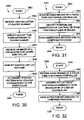
- FIGS. 24 and 25show flowcharts for interfacing with a computer program using video capture and audio monitoring, respectively.
- FIGS. 26 and 27show plan and rear elevation views, respectively, of an exemplary controller for interacting with the image capture device of FIG. 1 .
- FIGS. 28 and 29 ashow plan and rear elevation views, respectively, of a controller having a rectangular configuration of LEDs.
- FIG. 29 bshows a rear elevation view of a controller incorporates LEDs, a speaker, and a microphone.
- FIG. 29 cshows a rear elevation view of a controller having LEDs in a rectangular configuration along with centrally located speaker on a rear panel thereof.
- FIG. 29 dshows a rear elevation view of controller having five LEDs arranged in an arc formation.
- FIG. 29 eshows a rear elevation view of a controller having LEDs arranged in a wide rectangular configuration.
- FIG. 29 fshows a controller having six LEDs arranged in a cluster.
- FIG. 30shows flowchart depicting an exemplary procedure for determining what player corresponds to a particular controller when using an image capture device.
- FIG. 31shows a flowchart representing an exemplary procedure for identifying an orientation of a controller using an image capture device.
- FIG. 32shows a flowchart representing an exemplary procedure for identifying an orientation of a controller using an image capture device.
- FIG. 33shows controller having an interface containing a number of controls and a motion sensing device.
- FIG. 34shows a flowchart depicting an exemplary procedure communicating movement of controller to a computer program.
- a computer or gaming system having a video camera and/or audio sensing capabilitycan process image and audio data and identify various actions taking place in a zone of focus for the sensors. Such actions typically include manipulation of an object or creation of sounds, either by voice or by manipulating an object. Examples include pulling the trigger on a toy gun or moving or deforming an object.
- the present technologyfurther provides the additional functionality of sensing and determining an intensity amount associated with these actions. For example, how hard the trigger is pulled, to what extent is the object deformed, or how tightly is the baseball bat gripped. Using this additional parameter, video game manufacturers and others in fields relating to man-machine interactivity can greatly enhance the user experience. Specific examples of such are described below.
- game controller enhancementsto provide increased interactivity between a game controller and a game or other application.
- Such enhancementsinclude providing a plurality of LEDs on the game controller which are viewable by a video capture and processing system, allowing the video game or other application to identify the location, movement, or orientation of the game controller with respect to a video capture device.
- a game controllerhaving sound capture or sound or ultrasonic generation capability for accepting voice commands or communications with other users, and for providing communication between the controller and a base unit.
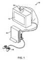
- FIG. 1illustrates an interactive game setup 100 , in accordance with one embodiment of the present invention.
- the interactive game setup 100includes a computer 102 , also referred to herein as “console,” that may be coupled to a display screen 110 .
- An image capture device 105may be placed on top of the display screen 110 and coupled to the computer 102 .
- Computer 102may be a gaming system console which allows users to play video games and interface with the video games through controllers 108 .
- the image capture device 105is shown placed on top of the display screen 110 , but it should be understood that the image capture device 105 can be placed in any other proximate location that will allow it to capture images that are located about in front of the display screen 110 .
- image capture device 105can be as simple as a standard web cam or can include more advanced technology.
- Image capture device 105may be capable of capturing images, digitizing the images, and communicating the image data back to the computer 102 .
- the image capture devicewill have logic integrated therein for performing the digitizing and another embodiment the image capture device 105 will simply transmit an analog video signal to the computer 102 for digitizing.
- the image capture device 105may be capable of capturing either color or black and white images of any object located in front of the image capture device 105 .
- FIG. 2illustrates an exemplary computer 102 for processing image data provided by the image capture device 105 to ascertain a pointing direction of an object placed in front of the image capture device 105 .
- the computer 102may be connected to the image capture device 105 .
- the image capture device 105may be designed to focus onto a capture region 105 a .
- a person 112may be intending to interact with a computer program being executed by the computer 102 .
- the computer programin this example, may be a video game which may be rendered and displayed by the display screen 110 .
- the video gameis a target shooting game in which the person 112 wishes to aim at a target and earn points commensurate with his or her performance.
- an image 112 ′ of the person 112may also be placed on the display screen 110 during game play.
- the person's image 112 ′may be omitted from the display screen, depending on the particular device under control or game being played.
- the user experiencemay be enhanced by illustrating an image 112 ′ of the person 112 during the target shooting exercise to present more reality during game play.
- a feature of the target shooting gamemay be the ability for person 112 to point or direct an object 124 at particular interactive graphics on the display screen 110 .
- the person 112will hold the object 124 with his or her hand 122 .
- the hand 122will be directionally pointed toward the display screen 110 .
- the image capture device 105will at this point, analyze the digital image capture of the person 112 to determine the location of the person's 112 head 120 , and the location of the person's 112 hand 122 .
- the person's 112 handmay be extended in front of his body and the image capture device will identify the object 124 when examining the captured digital image.
- the captured digital imagewill also be examined by code executed at the computer 102 to ascertain the location of the person's 112 head 120 .
- head trackingmay be completed with a combination of a template matching (for speed performance), coupled to a face detection code.
- the face detection codewill essentially identify the location of the user's face by locating the user's eyes and other facial features.
- the object 124will, in one embodiment, have an identifier which may be color or lights (e.g., light emitting diodes “LEDs”) coupled to the object so that the program analyzing the captured digital image will easily identify the location of the object 124 .
- an identifierwhich may be color or lights (e.g., light emitting diodes “LEDs”) coupled to the object so that the program analyzing the captured digital image will easily identify the location of the object 124 .
- the computer programwill perform computations to determine a relative angle from the image capture device position, and between the detected object 124 , and the head 120 .
- the relative position of the object 124 and the head 120will be calculated relative to the image capture device 105 .
- Thiswill produce two angle parameters (theta ⁇ and phi ⁇ ).
- the azimuth angle ⁇will define the horizontal positioning between the head 120 and the object 124 along an X axis.
- the phi angle ⁇will produce the altitude angle which is the relative angle between the height of the head 120 and the height of the hand 122 .
- an initial calibration operationmay be performed before a gaming operation begins to calibrate the object's pointing location on the display screen 110 . For instance, the user may be prompted to calibrate the pointing algorithm by having the user point the object 124 at a specific location on the display screen 110 .
- the computer 102will be able to calculate the azimuth angle and the altitude angle (theta and phi) which define the relative positions of the person's head 120 and the person's hand 122 , for each successive frame being captured by the image capture device 105 .
- the relative positioning between the head and the handmay be calculated for each captured frame or may be captured every other frame, or after a number of frames are captured, depending on the accuracy required for the pointing operation. For example, if the game is a shooting gallery game, it would be important for the relative positioning of the head 120 and the hand 122 to be computed for each frame so that the person 112 will have accurate aiming and triggering capabilities when attempting to secure a good performing score in the video game contest.
- FIG. 3is a block diagram of an exemplary user input system for interaction with an object on a graphical display that can be used to implement embodiments of the present invention.
- the user input systemmay be comprised of a video capture device 300 , an input image processor 302 , an output image processor 304 , and a video display device 306 .
- Video capture device 300may be any device capable of capturing sequences of video images, and, in one embodiment, may be a digital video camera (such as a “web-cam”), or similar image capturing device.
- the video capture device 300may be configured to provide depth image.
- depth cameraand “three-dimensional camera” refer to any camera that is capable of obtaining distance or depth information as well as two-dimensional pixel information.
- a depth cameracan utilize controlled infrared lighting to obtain distance information.
- Another exemplary depth cameracan be a stereo camera pair, which triangulates distance information using two standard cameras.
- depth sensing devicerefers to any type of device that is capable of obtaining distance information as well as two-dimensional pixel information.
- Camera 300can therefore provide the ability to capture and map the third-dimension in addition to normal two-dimensional video imagery. Similar to normal cameras, a depth camera captures two-dimensional data for a plurality of pixels that comprise the video image. These values are color values for the pixels, generally red, green, and blue (RGB) values for each pixel. In this manner, objects captured by the camera appear as two-dimension objects on a monitor. However, unlike a conventional camera, a depth camera also captures the z-components of the scene, which represent the depth values for the scene. Since the depth values are typically assigned to the z-axis, the depth values are often referred to as z-values.
- a z-valuemay be captured for each pixel of the scene.
- Each z-valuerepresents a distance from the camera to a particular object in the scene corresponding to the related pixel.
- a maximum detection rangemay be defined beyond which depth values will not be detected.
- This maximum range planecan be utilized by the embodiments of the present invention to provide user defined object tracking.
- each objectcan be tracked in three dimensions.
- a computer system of the embodiments of the present inventioncan utilize the z-values, along with the two-dimensional pixel data, to create an enhanced three-dimensional interactive environment for the user.
- U.S. patent application Ser. No. 10/448,614entitled System and Method for Providing a Real-time three dimensional interactive environment, having a filing date of May 29, 2003, which is incorporated herein by reference.
- input image processor 302translates the captured video images (which may be depth images) of the control object into signals that are delivered to an output image processor.
- input image processor 302may be programmed to isolate the control object from the background in the captured video image through the depth information and generate an output signal responsive to the position and/or movement of the control object.
- the output image processor 304may be programmed to effect translational and/or rotational movement of an object on the video display device 306 in response to signals received from the input image processor 302 .
- processorswhich execute software instructions.
- a single processorexecutes both input image processing and output image processing.
- the processing operationsare shown as being divided between an input image processor 302 and an output image processor 304 . It should be noted that the invention is in no way to be interpreted as limited to any special processor configuration, such as more than one processor.
- the multiple processing blocks shown in FIG. 3are shown only for convenience of description.
- FIG. 4is a simplified block diagram of a computer processing system configured to implement the embodiments of the invention described herein.
- the processing systemmay represent a computer-based entertainment system embodiment that includes central processing unit (“CPU”) 424 coupled to main memory 420 and graphical processing unit (“GPU”) 426 .
- CPU 424may also be coupled to Input/Output Processor (“IOP”) Bus 428 .
- GPU 426includes an internal buffer for fast processing of pixel based graphical data.
- GPU 426can include an output processing portion or functionality to convert the image data processed into standard television signals, for example NTSC or PAL, for transmission to display device 427 connected external to the entertainment system or elements thereof.
- data output signalscan be provided to a display device other than a television monitor, such as a computer monitor, LCD (Liquid Crystal Display) device, or other type of display device.
- IOP bus 428couples CPU 424 to various input/output devices and other busses or device. IOP bus 428 may be connected to input/output processor memory 430 , controller 432 , memory card 434 , Universal Serial Bus (USB) port 436 , IEEE1394 (also known as a Firewire interface) port 438 , and bus 450 .
- Bus 450couples several other system components to CPU 424 , including operating system (“OS”) ROM 440 , flash memory 442 , sound processing unit (“SPU”) 444 , optical disc controlling 4 , and hard disk drive (“HDD”) 448 .
- OSoperating system
- SPUsound processing unit
- HDDhard disk drive
- the video capture devicecan be directly connected to IOP bus 428 for transmission therethrough to CPU 424 ; where, data from the video capture device can be used to change or update the values used to generate the graphics images in GPU 426 .
- embodiments of the present inventioncan use a variety of image processing configurations and techniques, such as those described in U.S. patent application Ser. No. 10/365,120 filed Feb. 11, 2003, and entitled METHOD AND APPARATUS FOR REAL TIME MOTION CAPTURE, which may be hereby incorporated by reference in its entirety.
- the computer processing systemmay run on a CELLTM processor.
- FIG. 5is a block diagram of a configuration of the components of a video game console adapted for use with a manipulated object serving as an alternative input device in accordance with one embodiment of the invention.
- Exemplary game console 510may be equipped by a multiprocessor unit (MPU) 512 for control of overall console 510 , main memory 514 which may be used for various program operations and for storage of data, vector calculation unit 516 for performing floating point vector calculations necessary for geometry processing, image processor 520 for generating data based on controls from MPU 512 , and for outputting video signals to monitor 110 (for example a CRT), a graphics interface (GIF) 522 for carrying out mediation and the like over a transmission bus between MPU 512 or vector calculation unit 516 and image processor 520 , input/output port 524 for facilitating reception and transmission of a data to and from peripheral devices, internal OSD functional ROM (OSDROM) 526 constituted by, for example, a flash memory, for performing control of a kernel or the like, and real time clock 5
- Main memory 514 , vector calculation unit 516 , GIF 522 , OSDROM 526 , real time clock (RTC) 528 and input/output port 524are connected to MPU 512 over data bus 530 .
- image processing unit 538which is a processor for expanding compressed moving images and texture images, thereby developing the image data.
- the image processing unit 538can serve functions for decoding and development of bit streams according to the MPEG2 or MPEG4 standard formats, macroblock decoding, performing inverse discrete cosine transformations, color space conversion, vector quantization and the like.
- a sound systemmay be constituted by sound processing unit SPU 571 for generating musical or other sound effects on the basis of instructions from MPU 512 , sound buffer 573 into which waveform data may be recorded by SPU 571 , and speaker 575 for outputting the musical or other sound effects generated by SPU 571 .
- speaker 575may be incorporated as part of monitor 110 or may be provided as a separate audio line-out connection attached to external speaker 575 .
- Communications interface 540may also be provided, connected to BUS 530 , which is an interface having functions of input/output of digital data, and for input of digital contents according to the present invention.
- user input datamay be transmitted to, and status data received from, a server terminal on a network in order to accommodate on-line video gaming applications.
- Input device 532also known as a controller
- datae.g. key input data or coordinate data
- optical disk device 536for reproduction of the contents of optical disk 569 , for example a CD-ROM or the like on which various programs and data (i.e. data concerning objects, texture data and the like), are connected to input/output port 524 .
- the present inventionfurther includes digital video camera 105 which may be connected to input/output port 524 .
- Input/output port 524may be embodied by one or more input interfaces, including serial and USB interfaces, wherein digital video camera 190 may advantageously make use of the USB input or any other conventional interface appropriate for use with camera 105 .
- the above-mentioned image processor 520includes a rendering engine 570 , interface 572 , image memory 574 and a display control device 576 (e.g. a programmable CRT controller, or the like).
- the rendering engine 570executes operations for rendering of predetermined image data in the image memory, through memory interface 572 , and in correspondence with rendering commands which are supplied from MPU 512 .
- the rendering engine 570has the capability of rendering, in real time, image data of 320 ⁇ 240 pixels or 640 ⁇ 480 pixels, conforming to, for example, NTSC or PAL standards, and more specifically, at a rate greater than ten to several tens of times per interval of from 1/60 to 1/30 of a second.
- BUS 578may be connected between memory interface 572 and the rendering engine 570
- a second BUS 580may be connected between memory interface 572 and the image memory 574
- First BUS 578 and second BUS 580respectively, have a bit width of, for example 128 bits, and the rendering engine 570 may be capable of executing high speed rendering processing with respect to the image memory.
- Image memory 574employs a unified memory structure in which, for example, a texture rendering region and a display rendering region, can be set in a uniform area.
- Display controller 576may be structured so as to write the texture data which has been retrieved from optical disk 569 through optical disk device 536 , or texture data which has been created on main memory 514 , to the texture rendering region of image memory 574 , via memory interface 572 .
- Image data which has been rendered in the display rendering region of image memory 174may be read out via memory interface 572 , outputting the same to monitor 110 whereby it may be displayed on a screen thereof.
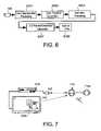
- FIG. 6is a block diagram showing the functional blocks used to track and discriminate a pixel group corresponding to the user input device as it is being manipulated by the user in accordance with one embodiment of the invention. It should be understood that the functions depicted by the blocks are implemented by software which may be executed by the MPU 512 in game console 510 of FIG. 5 . Moreover, not all of the functions indicted by the blocks in FIG. 6 are used for each embodiment.
- the pixel data input from the cameramay be supplied to game console 510 through input/output port interface 524 , enabling the following processes to be performed thereon.
- a color segmentation processing step S 201may be performed, whereby the color of each pixel is determined and the image is divided into various two-dimensional segments of different colors.
- a color transition localization step S 203may be performed, whereby regions where segments of different colors adjoin are more specifically determined, thereby defining the locations of the image in which distinct color transitions occur.
- a step for geometry processing S 205may be performed which, depending on the embodiment, comprises either an edge detection process or performing calculations for area statistics, to thereby define in algebraic or geometric terms the lines, curves and/or polygons corresponding to the edges of the object of interest.
- the three-dimensional position and orientation of the objectare calculated in step S 207 , according to algorithms which are to be described in association with the subsequent descriptions of preferred embodiments of the present invention.
- the data of three-dimensional position and orientationalso undergoes a processing step S 209 for Kalman filtering to improve performance. Such processing may be performed to estimate where the object is going to be at a point in time, and to reject spurious measurements that could not be possible, and therefore are considered to lie outside the true data set.
- Another reason for Kalman filteringis that the camera 105 produces images at 30 Hz, whereas the typical display runs at 60 Hz, so Kalman filtering fills the gaps in the data used for controlling action in the game program. Smoothing of discrete data via Kalman filtering is well known in the field of computer vision and hence will not be elaborated on further.
- FIG. 7is a schematic diagram of an exemplary embodiment of a deformable user deformable object 710 , which can exist in a relaxed state 710 A or a depressed state 710 B, according to the force applied to the deformable device by a user.
- deformable object 710may be in the form of a collapsible ball. More generally, any type of deformable object can be tracked by the visual tracking system described herein. It should be appreciated that in this embodiment, the area of deformable object 710 as seen by video digital camera 105 remains relatively constant. Thus, in addition to capturing X and Y planar movements of deformable device 310 , digital video camera 190 can also capture movement in the Z direction.
- the Z directioncan be used to pull a file, such as file 304 B forward or backwards, i.e., in a depth wise fashion as illustrated on monitor 110 .
- displayed objects that have been grabbed by deformable object 710can be made to appear smaller or larger, depending on the direction along the Z axis that deformable object 710 is moved. For example, if deformable object 710 is brought closer to camera 105 the displayed object will be made to appear larger while if deformable object 710 is moved away from camera 105 the displayed object will appear to be smaller on monitor 110 , in one embodiment.
- the displayed objectcan be made to change its size and location by a combination of movement if the X, Y and Z directions.
- an angle, theta ( ⁇ )may be used to determine the movement in three dimensional space.
- thetais an angle in the direction of the view plane of camera 190 .
- the cameracaptures the position of deformable object 710 .
- the positional informationmay be communicated to game console 510 .
- the positional informationmay be processed by game console 510 , as described above with reference to FIGS. 1-3 .
- the processingtranslates the movement to an object being displayed on monitor 110 .
- an audio signalcan be generated upon the change in aspect ratio of the deformable device in one embodiment of the invention.
- a passive button-press signalcan be included in the deformable device. Accordingly, the user would perceive a clicking experience even if the clicking noise is not sensed by the computing system.
- the x, y, z, ⁇ , and squeeze parametersare determined through the analysis of the pixels in the image.
- the pixels in the imageare part of the object, i.e., deformable device, being tracked.
- Xis proportional to the horizontal centroid of the pixels in the image.
- Yis proportional to the vertical centroid of the pixels in the image.
- Zis inversely proportional to the square root of either the area of the pixels or the principle second moment (producing different accuracy/robustness behavior).
- Theta ( ⁇ )corresponds to the rotation angle of the principle second moment.
- Squeeze parameterssuch as squeeze amount, i.e., amount of deformation or change in an aspect ratio, is proportional to the square root of the principle second moment divided by the square root of the minimal second moment.
- squeeze amounti.e., amount of deformation or change in an aspect ratio
- each of the above mentioned parameterscan be computed from a single pass through the image.
- the implementation described hereinis very fast and less sensitive to noise, i.e., visual error, than other commonly used metrics.
- FIG. 8shows an exemplary application in which a user 805 is manipulating deformable object 710 .
- Deformable object 710may be squeezed by hand 815 of user 805 .
- Camera 105 of console 510identifies that object 710 is deformed.
- a graphical representation of hand 815 ′picks up checker 817 on virtual checkerboard 820 . Thereafter movement of deformable object 710 can be translated into movement of the graphical representation of hand 815 ′.
- release checker 817user 805 relaxes hand 815 , thereby allowing deformable object 710 to return to its natural shape.
- FIG. 9shows an exemplary deformable object 900 in the form of a basketball.
- deformable object 900includes means causing it to illuminate when it is deformed.
- deformable object 900may be formed form a material that changes color when deformed. Color changing materials are known, and typically have a stress-sensitive fluorescent dye embedded in a translucent polymer matrix.
- deformable object 710may be made of a translucent foam rubber material having a shell of a color changing material.
- FIG. 10shows deformable object 900 having a light emitting diode layer (LED) 904 beneath outer layer 902 .
- Batteries 906are placed inside deformable object 900 .
- LED layer 904may comprise an LED blanket which lights up when deformed. In one embodiment, the more the object is deformed, the brighter the illumination. In another embodiment, the color of the illumination varies with the intensity of deformation. In one embodiment, the illumination only occurs in the portions of the object that are deformed. In a different embodiment, the entire object illuminates when deformed.
- the amount of deformationmay be sensed by the illuminating material itself.
- the materialmay be formed of multiple conducting layers that come into contact when the material is deformed, the contact closing a circuit. In one embodiment, only the region being deformed is illuminated. In another embodiment, the amount of deformation is sensed by a distinct strain gauge circuit, which may be disposed on layer 904 of deformable object 900 . In this case, deformation of the object causes the entire object to illuminate, with increasing brightness and/or color change in response to increasing deformation.
- FIG. 11shows an exemplary deformable object in the shape of a football 1100 .
- football 1100has a circuit disposed on layer 1108 .
- Layer 1108includes a deformation sensor 1110 and a plurality of illuminators 1106 .
- Illuminators 1106may be illuminating diodes, etc.
- football 1100has a battery compartment 1102 and a balance weight 1104 to balance football 1100 .
- battery compartment 1102may be quite small, e.g., the size for one or 2 size “AAA” batteries would be sufficient.
- the remainder of the volume within football 1100may be filled with soft foam rubber, allowing football 1100 to be readily squeezed.
- football 1100When football 1100 is squeezed, it deformation sensor 1110 detects the extent of deformation of football 1100 and generates illumination in response using illuminators 1106 .
- the brightness of the illuminationincreases with increasing deformation, or the color of the illumination changes with increasing deformation. Changes in color can be achieved by illuminating different colored LEDs. For example, at a low amount of deformation, green LEDs would illuminate. At increased amount of deformation, yellow, then red, then purple, then blue LEDs would illuminate. Thus a range of deformation amounts may be detected and then portrayed by changing the color of the illumination.
- Camera 105( FIG. 1 ) can detect the change in color of football 1100 and respond accordingly. For example, a virtual player portrayed on screen 110 can squeeze his virtual football in a manner consistent with the amount of deformation of football 1100 .
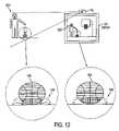
- FIG. 12shows an exemplary application for deformable object 900 in which deformable object 900 in the form of a basketball in use by user 1202 .
- User 1202is dribbling the basketball, which action may be received and interpreted by camera 105 .
- An image of a virtual ball player 1206may be presented on screen 110 .
- the action of virtual ball player 1206may be synchronized with the action of user 1202 .
- the deformed portions of the ballare illuminated as shown at 1204 , wherein the shaded areas represent increased illumination.
- Virtual player 1206bounces virtual ball 900 ′ which also “illuminates” or changes color as shown at 1208 .
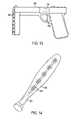
- FIG. 13shows a toy gun 1300 having a trigger 1302 and trigger sensor 1304 .
- Trigger sensor 1304can detect the intensity with which trigger 1302 is squeezed. The intensity can be measured, for example, using a strain gauge or other known means, such as potentiometer and spring. As the intensity of squeezing increases, illuminators 1306 increases in number or brightness and/or changes colors. One possible use may be to change from a single shot mode to a repeating or “machine gun” action mode when trigger 1302 is squeezed to a great amount.
- FIG. 14shows a toy baseball bat 1400 which may be made of translucent soft plastic or translucent foam rubber.
- Baseball bat 1400includes deformation sensors 1402 at the grip and a illuminators 1404 along a length of the bat. As the user increases his or her grip on bat 1400 , illuminators 1404 increase in number or brightness and/or changes colors.
- console 510may be able to sense an extent of deformation by measuring a percent change in aspect ratio of deformable object 710 .
- console 510can rely in part or in full on such changes to determine an intensity value relative to the extent of deformation.
- stress-sensitive materials or embedded circuitrythere may be no limit on the shape of the deformable object. This opens up new possibilities in man-machine interactivity. For example, the tightness with which a baseball bat is gripped can be used to as a measure of how hard the swing is in a baseball simulation.
- computersare using various techniques such as posture and facial expression to identify the mood of the user.
- the present technologyallows game developers to modify game play based on intensity values exhibited by a user. For example, an intensity value which can be indicative of such emotions as fear, anger, or excitement can be sensed by how tightly a toy gun is being gripped, which can then be used to alter computer-generated character responses.
- intensity of interactioncan be received by sound in addition to, or instead of, by imaging.
- a monitor 1506shown by way of example in FIG. 15 , which includes image capture unit 1506 b and a sound capture unit 1506 a .
- a sound sourcecan be a noise generated by an input object, device, a hand clap or a foot tap, or any other noise.
- the soundwill then be captured by the sound capture unit 1506 a , and processed by the computing system 102 ( FIG. 1 ) for interaction.
- Voice recognitionmay be used to enable the identification of voice commands.
- the usermay be in communication with remote users connected to the Internet or network, but who are also directly or partially involved in the interactivity of the game.
- the sound capture unit 1506 amay be configured to include at least two microphones which will enable the computing system 102 to select sound coming from particular directions. By enabling the computing system 102 to filter out sounds from directions which are not central to the interactivity, distracting sounds in the environment will not interfere with or confuse the execution of the interactive program determining an intensity value of the sound generated by the input object, device, or other means.
- the sound capture unitcan isolate sounds from a target focus zone to reliably identify an intensity value.
- the zone of focusmay be identified by the active image area that is the focus point of the image capture unit 1506 b . In an alternative manner, the zone of focus can be manually selected from a choice of zones presented to the user after an initialization stage.
- the image-sound capture device 1506includes an image capture unit 1506 b , and the sound capture unit 1506 a .
- the image-sound capture device 1506may be capable of digitally capturing image frames and then transferring those image frames to the computing system 102 ( FIG. 1 ) for further processing.
- An example of the image capture unit 1506 bmay be a web camera, which is commonly used when video images are desired to be captured and then transferred digitally to a computing device for subsequent storage or communication over a network, such as the Internet.
- Other types of image capture devicesare also contemplated, whether analog or digital, so long as the image data is digitally processed to enable the identification and filtering.
- the digital processing to enable the filtering.may be done in software, after the input data is received.
- the sound capture unit 1506 ais shown including a pair of microphones (MIC 1 and MIC 2 ).
- the microphonesare standard microphones, which can be integrated into the housing that makes up the image-sound capture device 1506 .
- FIG. 16illustrates sound capture units 1506 a when confronted with sound sources 1616 from sound A and sound B.
- sound Awill project its audible sound and will be detected by MIC 1 and MIC 2 along sound paths 1601 a and 1601 b .
- Sound Bwill be projected toward MIC 1 and MIC 2 over sound paths 1602 a and 1602 b .
- the sound paths for sound Awill be of different lengths, thus providing for a relative delay when compared to sound paths 1602 a and 1602 b .
- the sound coming from each of sound A and sound Bwill then be processed using a standard triangulation algorithm so that direction selection can occur in box 1716 , shown in FIG. 17 .
- the sound coming from MIC 1 and MIC 2will each be buffered in buffers 1 and 2 ( 1710 a , 1710 b ), and passed through delay lines ( 1712 a , 1712 b ).
- the buffering and delay processwill be controlled by software, although hardware can be custom designed to handle the operations as well.
- direction selection 1716will trigger identification and selection of one of the sound sources 1616 .
- the sound coming from each of MICs 1 and MICs 2will be summed in box 1714 before being output as the output of the selected source. In this manner, sound coming from directions other than the direction in the active image area will be filtered out so that such sound sources do not distract processing by the computer system 102 ( FIG. 1 ) or distract communication with other users that may be interactively playing a video game over a network, or the Internet.
- a video game or other application utilizing this technologycan reliably identify and quantify an intensity value of a sound originating from a zone of focus at a predetermined or selected direction relative the sound capture device.
- the intensity valuemay correlate to the loudness or volume of the sound, the rapidity of the sound, and/or the pitch of the sound. Rapidity is the number of repetitions of a sound in a particular segment of time. In some instances, the intensity may be greater at higher volumes, greater rapidity, or higher pitch. In other instances, the intensity may be greater at reduced volumes, less rapidity, or lower pitch, depending on the application. In any case, isolating the sound from ambient sound and other sound generated in the room enables a more reliable determination of the intensity amount.
- FIG. 18illustrates a computing system 1850 that may be used in conjunction with the image-sound capture device 1506 , in accordance with one embodiment of the present invention.
- the computing system 1850includes a processor 1852 , and memory 1856 .
- a bus 1854will interconnect the processor and the memory 1856 with the image-sound capture device 1506 .
- the memory 1856will include at least part of the interactive program 1858 , and also include selective sound source listening logic or code 1860 for processing the received sound source data. Based on where the zone of focus is identified to be by the image capture unit 1506 b , sound sources outside of the zone of focus will be selectively filtered by the selective sound source listening logic 1860 being executed (e.g., by the processor and stored at least partially in the memory 1856 ).
- the computing systemis shown in its most simplistic form, but emphasis is placed on the fact that any hardware configuration can be used, so long as the hardware can process the instructions to effect the processing of the incoming sound sources and thus enable the selective listening.
- the computing system 1850is also shown interconnected with the display 110 by way of the bus.
- the zone of focusmay be identified by the image capture unit being focused toward the sound source B. Sound coming from other sound sources, such as sound source A will be substantially filtered out by the selective sound source listening logic 1860 when the sound is captured by the sound capture unit 1506 a and transferred to the computing system 1850 .
- a playercan be participating in an Internet or networked video game competition with another user where each user's primary audible experience will be by way of speakers.
- the speakersmay be part of the computing system or may be part of the monitor 1506 .
- the local speakersare what may be generating sound source A as shown in FIG. 4 .
- the selective sound source listening logic 1860will filter out the sound of sound source A so that the competing user will not be provided with feedback of his or her own sound or voice. By supplying this filtering, it is possible to have interactive communication over a network while interfacing with a video game, while advantageously avoiding destructive feedback during the process.
- FIG. 19illustrates an exemplary monitor 1506 including at least four microphones (MIC 1 through MIC 4 ).
- the sound capture unit 1506 ais therefore capable of triangulation with better granularity to identify the location of sound sources 1616 (A and B). That is, by providing an additional microphone, it is possible to more accurately define the location of the sound sources and thus, eliminate and filter out sound sources that are not of interest or can be destructive to game play or interactivity with a computing system.
- sound source 1616 (B)may be the sound source of interest as identified by the video capture unit 1506 b .
- FIG. 19identifies how sound source B is identified to a spatial volume.
- the spatial volume at which sound source B is locatedwill define the volume of focus 1974 .
- the image-sound capture device monitor 1506will preferably include at least four microphones. At least one of the microphones will be in a different plane than three of the microphones. By maintaining one of the microphones in plane 1971 and the remainder of the four in plane 1970 of the image-sound capture device monitor 1506 , it is possible to define a spatial volume.
- noise coming from other people in the vicinity(shown as 1976 a and 1976 b ) will be filtered out as they do not lie within the spatial volume defined in the volume focus 1974 . Additionally, noise that may be created just outside of the spatial volume, as shown by speaker 1976 c , will also be filtered out as it falls outside of the spatial volume.
- the voice input systemmay be capable of isolating a target audio signal from multiple noise signals. Additionally, there are no constraints on the movement of the portable consumer device, which has the microphone array affixed thereto.
- the microphone array frameworkincludes four main modules in one embodiment of the invention.
- the first modulemay be an acoustic echo cancellation (AEC) module.
- the AEC modulemay be configured to cancel portable consumer device generated noises. For example, where the portable consumer device is a video game controller, the noises, associated with video game play, i.e., music, explosions, voices, etc., are all known.
- a filter applied to the signal from each of the microphone sensors of the microphone arraymay remove these known device generated noises.
- the AEC modulemay be optional and may not be included with the modules described below. Further details on acoustic echo cancellation may be found in “Frequency-Domain and Multirate Adaptive Filtering” by John J. Shynk, IEEE Signal Processing Magazine, pp. 14-37, January 1992. This article is incorporated by reference for all purposes.
- FIG. 20is a simplified schematic diagram illustrating an array beam-forming module configured to suppress a signal not coming from a listening direction in accordance with one embodiment of the invention.
- the beam-formingmay be based on filter-and-sum beam-forming.
- the finite impulse response (FIR) filtersalso referred to as signal passing filters, are generated through an array calibration process which may be adaptive.
- the beam-formingmay be essentially an adaptive beam-former that can track and steer the beam, i.e., listening direction, toward a source signal 2028 without physical movement of the sensor array.
- beam-formingwhich refers to methods that can have signals from a focal direction enhanced, may be thought of as a process to algorithmically (not physically) steer microphone sensors 2012 - 1 through 2012 -M towards a desired target signal.
- the direction that the sensors 112 - 1 through 112 -M look atmay be referred to as the beam-forming direction or listening direction, which may either be fixed or adaptive at run time.
- the fundamental idea behind beam-formingis that the sound signals from a desired source reaches the array of microphone sensors with different time delays.
- the geometry placement of the arraybeing pre-calibrated, thus, the path-length-difference between the sound source and sensor array is a known parameter. Therefore, a process referred to as cross-correlation may be used to time-align signals from different sensors.
- the time-align signals from various sensorsare weighted according to the beam-forming direction.
- the weighted signalsare then filtered in terms of sensor-specific noise-cancellation setup, i.e., each sensor may be associated with a filter, referred to as a matched filter F 1 F M , 2042 - 1 through 2042 -M, which are included in signal-passing-filter 2062 .
- the filtered signals from each sensorare then summed together through module 2072 to generate output Z( ⁇ , ⁇ ).
- the above-described processmay be referred to as auto-correlation.
- the signals that do not lie along the beam-forming directionremain misaligned along the time axes, these signals become attenuated by the averaging.
- the overall performance of the microphone array to capture sound from a desired spatial directionusing straight line geometry placement) or spatial volumes (using convex geometry array placement) depends on the ability to locate and track the sound source.
- an environment with complicated reverberation noisee.g., a videogame environment, it is practically infeasible to build a general sound location tracking system without integrating the environmental specific parameters.
- the adaptive beam-formingmay be alternatively explained as a two-part process.
- the broadside noiseis assumed to be in a far field. That is, the distance from source 2028 to microphone centers 2012 - 1 through 2012 -M is large enough so that it may be initially assumed that source 2028 is located on a normal to each of the microphone sensors. For example, with reference to microphone sensor 2012 - m the source would be located along normal 2036 .
- the broadside noisemay be enhanced by applying a filter referred to as F 1 herein.
- a signal passing filterthat may be calibrated periodically may be configured to determine a factor, referred to as F 2 , that allows the microphone sensor array to adapt to movement.
- the signal passing filtermay be calibrated every 100 milliseconds. Thus, every 100 milliseconds the signal passing filter may be applied to the fixed beam-forming.
- matched filters 2042 - 1 through 2042 -Msupply a steering factor, F 2 , for each microphone, thereby adjusting the listening direction as illustrated by lines 2038 - 1 through 2038 -M.
- F 2steering factor
- FIG. 21shows a high level schematic diagram illustrating a blind source separation scheme for separating the noise and source signal components of an audio signal.
- explicit knowledge of the source signal and the noise within the audio signalmay not be available.
- the characteristics of the source signal and the noiseare different.
- a first speaker's audio signalmay be distinguished from a second speaker's audio signal because their voices are different and the type of noise is different.
- data 2150 representing the incoming audio signalwhich includes noise and a source signal, may be separated into a noise component 2152 and source signal 2154 through a data mining operation. Separation filter 2160 then separates the source signal 2150 from the noise signal 2152 .
- one method for performing the data miningmay be through independent component analysis (ICA) which analyzes the data and finds independent components through second order statistics in accordance with one embodiment of the invention.
- ICAindependent component analysis
- a second order statisticmay be calculated to describe or define the characteristics of the data in order to capture a sound fingerprint which distinguishes the various sounds.
- the separation filtermay then enabled to separate the source signal from the noise signal. It should be appreciated that the computation of the sound fingerprint may be periodically performed.
- the listening directionmay be adjusted each period.
- the time arrival of delaysmay be determined for use in tracking source signal 2154 .
- the second order of statistics referred to abovemay be referred to as an auto correlation or cross correlation scheme. Further details on blind source separation using second order statistics may be found in the article entitled “System Identification Using Non-Stationary Signals” by O. Shalvi and E. Weinstein, IEEE Transactions on Signal Processing, vol-44(no. 8): 2055-2063, August, 1996. This article is hereby incorporated by reference for all purposes.
- FIG. 22is a schematic diagram illustrating a microphone array framework that incorporates adaptive noise cancellation.
- Audio signal 2266which includes noise and a source signal may be received through a microphone sensor array which may be affixed to a portable consumer device 102 , e.g., a videogame console or computing device.
- the audio signal received by portable consumer device 102may then be pre-processed through acoustic echo cancellation (AEC) module 168 .
- AECacoustic echo cancellation
- acoustic echo cancellationmay be performed as described by way of example in U.S. patent application Ser. No. 10/650,409, which is incorporated herein by reference.
- Signals Z 1 through Z Mwhich correspond to the number of microphone sensors in the microphone array, are generated and distributed over channels 2270 - 1 through 2270 -M. It should be appreciated that channel 2270 - 1 may be a reference channel. The corresponding signals are then delivered to filter-and-sum module 2062 . It should be appreciated that filter-and-sum module 2062 performs the adaptive beam-forming as described above with reference to FIG. 20 . At the same time, signals from channels 2270 - 1 through 2270 -M are delivered to blocking filter 2264 .
- Blocking filter 2264may be configured to perform reverse beam-forming where the target signal may be viewed as noise. Thus, blocking filter 2264 attenuates the source signal and enhances noise. That is, blocking filter 2264 may be configured to determine a calibration coefficient F 3 which may be considered the inverse of calibration coefficient F 2 determined by the adaptive beam-forming process.
- Filter-and-sum module 2062 and blocking filter module 2264make up separation filter 2160 . Noise enhanced signals U 2 through U M are then transmitted to corresponding adaptive filters 2275 - 2 through 2275 -M, respectively.
- Adaptive filters 2275 - 2 through 2275 -Mare included in adaptive filter module 2274 .
- adaptive filters 2275 - 2 through 2275 -Mare configured to align the corresponding signals for the summation operation in module 2276 .
- the noisemay not stationary, therefore, the signals must be aligned prior to the summation operation.
- the signal from the summation operation of module 2276may then combined with the signal output from summation operation in module 2272 in order to provide a reduced noise signal through the summation operation module 2278 . That is, the enhanced signal output for module 2272 may be combined with the enhanced noise signal from module 2276 in a manner that enhances the desired source signal.
- block 2280represents the adaptive noise cancellation operation. Additionally, the array calibration occurring in the background may take place every 100 milliseconds as long as a detected signal-to-noise-ratio may be above zero decibels in one embodiment.
- the array calibrationupdates the signal-passing-filter used in filter-and-sum beam-former 2062 and signal-blocking-filter 2264 that generates pure interferences whose signal-to-noise-ratio may be less than ⁇ 100 decibels.
- the microphone sensor array output signalmay be passed through a post-processing module to further refine the voice quality based on person-dependent voice spectrum filtering by Bayesian statistic modeling. Further information on voice spectrum filtering may be found in the article entitled “Speech Enhancement Using a Mixture-Maximum Model” by David Burshtein, IEEE Transactions on Speech and Audio Processing vol. 10, No. 6, September 2002. This article in incorporated by reference for all purposes. It should be appreciated that the signal processing algorithms mentioned herein are carried out in the frequency domain. In addition, a fast and efficient Fast Fourier transform (FFT) may be applied to reach real time signal response.
- FFTFast and efficient Fast Fourier transform
- the implemented softwarerequires 25 FFT operations with window length of 1024 for every signal input chunk (512 signal samples in a 16 kHz sampling rate).
- the total computation involvedmay be about 250 mega floating point operations (250M Flops).
- separation filter 2160may be decomposed into two orthogonal components that lie in the range and null space by QR orthogonalization procedures. That is, the signal blocking filter coefficient, F 3 , may be obtained from the null space and the signal passing filter coefficient, F 2 , may be obtained from the rank space.
- This processmay be characterized as Generalized Sidelobe Canceler (GSC) approach. Further details of the GSC approach may be found in the article entitled “Beamforming: A Versatile Approach to Spatial Filtering” which has been incorporated by reference above.
- the above described embodimentdescribes a method and a system for providing audio input in a high noise environment.
- the audio input systemincludes a microphone array that may be affixed to a video game controller, e.g., a SONY PLAYSTATION 2® video game controller or any other suitable video game controller.
- the microphone arraymay be configured so as to not place any constraints on the movement of the video game controller.
- the signals received by the microphone sensors of the microphone arrayare assumed to include a foreground speaker or audio signal and various background noises including room reverberation. Since the time-delay between background and foreground from various sensors may be different, their second-order statistics in frequency spectrum domain are independent of each other, therefore, the signals may be separated on a frequency component basis.
- the separated signal frequency componentsare recombined to reconstruct the foreground desired audio signal.
- the embodiments described hereindefine a real time voice input system for issuing commands for a video game, or communicating with other players within a noisy environment.
- FIG. 23shows an exemplary toy gun 2300 having a trigger 2301 and a trigger sensor 2304 .
- toy gun 2300contains a marble 2302 .
- marble 2302comprises a solid metal ball bearing.
- the usercan flick gun 2300 cause marble 2302 to slide forward to position 2302 ′ to make a loud “crack” sound, which can then be perceived by monitor 1506 .
- the usercan squeeze trigger 2301 , which may be sensed by trigger sensor 2304 .
- Toy gun 2300contains a circuit 2306 that generates a gun shot sound effect out of speaker 2308 .
- the harder trigger 2301may be squeezed, the more rapidly the gunshot effect, or different effects, are produced.
- Computing system 1850FIG.
- a sound generatedmay be at a higher or different pitch (frequency). The higher the pitch the increased intensity may be obtainable by monitor 1506 .
- FIG. 20While a toy gun is shown in FIG. 20 , persons skilled in the art will recognize that other input devices, such as a plush doll, ball, or other implement or toy can be imagined and used with the audio capture 1506 a .
- the exemplary embodiment described hereshows how changes in sound volume, frequency, or rapidity can be interpreted by a computer system to identify an intensity value indicating an interaction with an interface object.
- a toy dollmay respond differently to being hugged or squeezed by generating-different sounds which can be picked up by the sound capture unit.
- FIG. 24illustrates a flowchart diagram 2400 .
- the procedurebegins as indicated by start block 2402 and proceeds to operation 2404 wherein a capture region may be monitored using a capture device that has video and/or audio capture capability.
- the procedureflows to operation 2406 wherein an input device may be detected within the capture region.
- An initial shape of the input devicemay be detected.
- the input devicecan be detected by its color or shape. For example, if the input device is an orange ball, the video monitor will look for a round orange shape and determine that that is the input device.
- the procedurecontinues at operation 2408 wherein the extent of change of shape, color, or brightness of the input device may be detected.
- the input devicechanges color or becomes increasingly illuminated when deformed.
- the input devicesimply changes shape, e.g., when squeezed by a user.
- the video monitorcan detect the change in shape, color, or brightness of the device and identify an intensity value from the extent of change.
- the procedurecontinues with operation 2410 wherein an activity input is triggered by the computer program being run on a computer in communication with the capture device.
- the activity inputcan include the intensity value calculated from the extent of deformation, illumination, or color perceived by the video capture device.
- the procedurethen ends as indicated by finish block 2412 .
- FIG. 25shows a second flowchart 2500 .
- a capture regionmay be monitored using a capture device having video and audio capability as indicated in operation 2504 .
- a sound generated by an input devicemay be detected.
- the procedurethen flows to operation 2508 wherein an intensity value may be calculated based on a loudness or rapidity of sound generated by the input device.
- a frequency (pitch) of the soundcan be used to determine the intensity value.
- an activity inputmay be provided to a computer program being run on a computer that may be in communication with the capture device.
- the activity inputmay include a value representative of the intensity value determined from the sound generated by the input device.
- the procedurethen ends as indicated by finish block 2512 .
- a video game controllermay typically a hand-held device having buttons, knobs, and/or joysticks for providing input into a video game program for controlling action within the game. It would be desirable to add additional functionality to the controller by sensing movement and/or rotation of the controller in space. Thus, a user, for example, can steer a virtual racecar by tilting the whole controller device, which can then be sensed by an image capture device as described above with reference to FIGS. 1-14 .
- video game controllersprovide a stream of analog signals and/or digital data over a cable or wirelessly using one or more of available infra-red or radio frequency (RF) interfaces.
- RFradio frequency
- more than one controllermay be placed into electronic communication with the computer system (e.g., the game console).
- Each person interacting with the programmay be assigned a number, e.g., “Player 1 ,” “Player 2 ,” etc.
- game controllersWhen game controllers are connected to the system, each user can be assigned a number according to the port number to which the controller is connected. Thus, if a computer game has four ports, Player 1 is connected to port number 1 , Player 2 is connected to port number 2 , etc.
- Wireless controllersallow players to select their player number based on a wireless channel or other hand-shake protocol mechanism allowing the controller to identify itself as for Player 1 , Player 2 , and so on.
- FIGS. 26 and 27show an exemplary controller 2600 that interacts with an image capture device 105 ( FIG. 1 ).
- Controller 2600includes an interface 2602 containing a plurality of interface devices including various buttons and joysticks.
- the controllers discussed hereincan be either wired or wireless. Technologies, such as WiFi, BluetoothTM, IR, sound, and lights may work to interface with a computer, such as a game console.
- controller 2600has an LED array 2605 .
- the LED arraymay be configured in various layouts, including a 2 ⁇ 2 stack where each LEDs may be positioned at a vertex of an imaginary rectangular or square-shaped binding box.
- LED array 2605may generate infrared or visible light.
- Image capture device 105FIG. 1
- Each controllercan be designated as Player 1 through, for example, Player 4 , using switch 2610 , which allows a user selection of player number 1-4.
- Each player number selectioncorresponds to a unique pattern or modulation of LEDs being illuminated by LED array 2605 . For example, for Player 1 , 1st, 3rd, and 5th LEDs are illuminated.
- Such player informationmay be encoded and transmitted in a repeated fashion over time across multiple video frames. It may be desirable to engage in an interleave scheme so the controller or device LEDS can switch between a tracking mode and a transmission mode. In the tracking mode, all LEDs may be turned on during a first portion of a cycle. In the transmission mode, information may be modulated by the LEDs during a second portion of a cycle. Over time, the LEDS transmit tracking and communications information to a video analyzer or suitable device capable of receiving the signal. In the transmission mode, the LEDs may encode information representative of the player I.D. The period and duty cycle may be chosen to accommodate speed of tracking, lighting conditions, number of controllers, etc.
- a video capture devicemay be supplied with adequate information to compute tracking parameters for each controller and to discriminate between controllers. Such discrimination may be used in a video analyzer to isolate each physical controller when monitoring and tracking the position and orientation and other metrics of the controller movement.
- other informationincluding commands 1 or state information may be transmitted by the controller or device LEDs and according to known encoding and modulation schemes.
- a video analyzer coupled to the video capture devicemay sync with and track the state of the LEDS and decode the information and controller movements. It is known that higher bandwidth may be achieved by modulating-data across frames in the transmission mode cycle.
- User interaction with interface 2602may cause one or more of LEDs in LED array 2605 to modulate and/or change color.
- a joystick LEDsmay change brightness or transmit information.
- the changes in intensity or colorcan be monitored by the computer system and provided to a gaming program as an intensity value as described above with reference to FIGS. 1-14 .
- each buttonmay be mapped to a change in color or intensity of one or more of the LEDs in LED array 2605 .
- image capture device 105 in conjunction with computer system 102may be capable of identifying these changes and generating a two dimensional vector (for describing movement on the image plane, or a three dimensional vector for describing movement in three dimensional space.
- the vectorcan be provided as a series of coordinates describing relative movement and/or an absolute position with respect to the image capture device 105 .
- movement on a plane perpendicular to the line of sight of image capture device 105can be identified by an absolute position within the image capture zone, while movement of controller 2600 closer to image capture device 105 can be identified by LED array 2605 appearing to spread out, i.e., the distance between the first and last LED on the image plane can be measured to calculate distance from the image capture device.
- FIGS. 28 and 29 ashow a controller 2800 having a rectangular configuration of LEDs 2805 , thereby allowing movement of controller 2800 on three and rotation about each axis to be detected.
- controller 2800may be pitched forward or backward, the top and bottom LEDs will get closer to each other while the left and right LEDs remain the same distance apart.
- controller 2800yaws left or right, the left and right LEDs will appear to approach each other while the top and bottom LEDs remain the same distance apart.
- Rolling motion of controller 2800can be detected by identifying the orientation of the LEDs on the image plane.
- LED modulationcan be used to identify user interactions with interface 2802 .
- FIG. 29 bshows controller 2920 according to another embodiment, which incorporates LEDs 2922 , a speaker 2924 , and a microphone 2926 .
- LEDs 2922provide position and orientation information using an image capture device, while speaker 2924 can generate audible or ultrasonic sound, providing sound effects and/or communication using an audio monitor as described above with reference to FIGS. 15-23 .
- Microphone 2926provides sound input to the system, which can be used for issuing voice commands, or for communicating with other players in an on-line multiplayer environment.
- FIG. 29 cshows a controller 2930 having LEDs 2932 in a rectangular configuration along with centrally located speaker on a rear panel of controller 2930 .
- FIG. 29 dshows a controller 2940 having five LEDs 2942 arranged in an arc formation.
- FIG. 29 eshows a controller 2950 having LEDs arranged in a wide rectangular configuration.
- FIG. 29 fshows a controller 2960 having six LEDs 296 arranged in a cluster.
- FIG. 30shows flowchart 3000 depicting an exemplary procedure for determining what player corresponds to a particular controller when using an image capture device.
- the procedurebegins as indicated at start block 3002 and flows to operation 3004 .
- the playerselects what player number he or she wants and that selection may be received by the controller.
- the procedurethen flows to operation 3006 wherein an LED pattern may be displayed that corresponds to the player number selected by the user.
- an image of the focus zone containing the controlleris received by an image capture device which may be connected to a computer.
- the computerhaving received data representing the image, identifies in operation 3010 the LED pattern generated by the controller, and, in operation 3012 , determines from the LED pattern which player corresponds to that controller.
- the procedurethen ends as indicated by finish block 3014 .
- FIG. 31shows a flowchart 3100 representing an exemplary procedure for identifying an orientation of a controller using an image capture device.
- the procedurebegins as indicated by start block 3102 and flows to operation 3104 , wherein video images of a focus zone containing a controller are received.
- the orientation and/or position of the controllermay be identified from the absolute and relative positions of the LEDs on the controller. The orientation and position can be obtained as described above with reference to FIGS. 28 and 29 .
- the procedureflows to operation 3108 wherein data representing the orientation and/or position of the controller is passed to a computer program which requested or is otherwise receptive to the data.
- the procedurethen ends as indicated by finish block 3110 .
- FIG. 32shows a flowchart 3200 representing an exemplary procedure for identifying an orientation of a controller using an image capture device.
- the procedurebegins as indicated by start block 3202 and flows to operation 3204 , wherein video images of a focus zone containing a controller are received.
- operation 3206actuation of the interface of the controller, e.g., buttons, switches, joysticks, etc., may be identified from controller LED modulation. This operation may be carried out as described above with reference to FIGS. 26-27 .
- the actuation informationmay then passed to the computer program.
- finish block 3210the procedure ends as indicated by finish block 3210 .
- FIG. 33shows controller 3300 having an interface 3302 containing a number of controls and a motion sensing device 3305 therein.
- motion sensing device 3305may be a three axis accelerometer.
- Accelerometersare generally known in the field of electronics, and typically comprise a small solid state device having structures that respond to changes in momentum, and sensors that detect the responses.
- Miniaturized accelerometersare available for sensing translational movements as well as rotational movements. Translational movements are movements along x, y, and z axes. Rotational movements are rotations about one or more of the x, y, and z axes.
- Translation-detecting accelerometerscan detect the direction of the pull of gravity, and therefore identify the absolute orientation of a device (such as a game controller) with respect to the pull of gravity.
- Controller 3300includes a translation sensing accelerometer 3305 , which generates digital data received by a circuit (not shown) contained within controller 3300 .
- the digital datacan be converted into translational movement vectors and orientation of the device, determinable from the pull of gravity on the device.
- the circuitidentifies motion and orientation of controller 3300 and transmits this data along with other data representing user interaction with various controls of interface 3302 .
- to the game consolein a manner generally known in the art, e.g., via a cable, infra-red, or radio connection. It is also possible to encode the data into LED modulations for viewing by an image capture device.
- the motion captured by the devicecan be represented as absolute position and orientation information (taking an initial position as the origin) and/or change in position and orientation.
- FIG. 34shows a flowchart 3400 depicting an exemplary procedure communicating movement of controller 3300 to a computer program.
- the procedurebegins as indicated by start block 3402 and proceeds to operation 3404 wherein the motion of the game controller may be detected.
- motionmay be detected by detecting changes in momentum of the controller, which may be detected using an accelerometer.
- the changes in momentummay then be converted into movement vectors and/or absolute position vector from an initial origin, and a vector representing the pull of gravity, which identifies the orientation of controller 3300 .
- the movement, position, and orientation vectorscan be represented as a series of coordinates.
- the procedureflows to operation 3406 wherein data representing the detected motion may be passed to the program which requested the data or may be otherwise receptive to the data.
- the image or audio processing functions described above for determining the intensity value, controller player number, orientation and/or position of one or more input objects including controllersmay be carried out in a process executing on a computer system.
- the computing systemmay be also executing a main process, which may be a gaming application, that requests or is otherwise receptive to the data generated from the image or audio processing, such data comprising the intensity value, controller player number, orientation and/or position of one or more input objects including controllers, controller actuation, etc.
- the process performing the image and/or audio processing functionsmay be a driver for a video camera or video/audio monitoring device, the driver providing the data to the main process via any type of inter-process communication which-may be implementation specific as generally known and understood in the art.
- the process performing image or audio processingexecutes on the same processor or a different processor as the one executing the gaming or other software. It may also be possible to have a common process for both image or audio processing and game functionality in the same process, e.g., using a procedure call.
- the intensity value or other informationmay be provided “to the program” it should be recognized that the invention encompasses providing such data to one routine of a process using a procedure call or other software function such that a single process can both perform image processing functionality as well as gaming functionality, as well as separating the functions into different processes whereby one or more processes, which may execute on a common processor core or multiple processor cores, perform image and/or audio processing as described herein and a separate process performs gaming functions.
- the present inventionmay be used as presented herein or in combination with other user input mechansims and notwithstanding mechanisms that track the angular direction of the sound and/or mechansims that track the position of the object actively or passively, mechanisms using machine vision, combinations thereof and where the object tracked may include ancillary controls or buttons that manipulate feedback to the system and where such feedback may include but is not limited light emission from light sources, sound distortion means, or other suitable transmitters and modulators as well as buttons, pressure pad, etc. that may influence the transmission or modulation of the same, encode state, and/or transmit commands from or to the device being tracked.
- the inventionmay be practiced with other computer system configurations including game consoles, gaming computers or computing devices, hand-held devices, microprocessor systems, microprocessor-based or programmable consumer electronics, minicomputers, mainframe computers and the like.
- the inventionmay also be practiced in distributing computing environments where tasks are performed by remote processing devices that are linked through a network. For instance, on-line gaming systems and software may also be used.
- the inventionmay employ various computer-implemented operations involving data stored in computer systems. These operations are those requiring physical manipulation of physical quantities. Usually, though not necessarily, these quantities take the form of electrical or magnetic signals capable of being stored, transferred, combined, compared, and otherwise manipulated. Further, the manipulations performed are often referred to in terms, such as producing, identifying, determining, or comparing.
- the inventionalso relates to a device or an apparatus for performing these operations.
- the apparatusmay be specially constructed for the required purposes, such as the carrier network discussed above, or it may be a general purpose computer selectively activated or configured by a computer program stored in the computer.
- various general purpose machinesmay be used with computer programs written in accordance with the teachings herein, or it may be more convenient to construct a more specialized apparatus to perform the required operations.
- the inventioncan also be embodied as computer readable code on a computer readable medium.
- the computer readable mediummay be any data storage device that can store data, which can thereafter be read by a computer system. Examples of the computer readable medium include hard drives, network attached storage (NAS), read-only memory, random-access memory, FLASH based memory, CD-ROMs, CD-Rs, CD-RWs, DVDs, magnetic tapes, and other optical and non-optical data storage devices.
- the computer readable mediumcan also be distributed over a network coupled computer systems so that the computer readable code may be stored and executed in a distributed fashion.
Landscapes
- Engineering & Computer Science (AREA)
- Multimedia (AREA)
- Human Computer Interaction (AREA)
- General Engineering & Computer Science (AREA)
- Physics & Mathematics (AREA)
- Theoretical Computer Science (AREA)
- Optics & Photonics (AREA)
- General Physics & Mathematics (AREA)
- Acoustics & Sound (AREA)
- User Interface Of Digital Computer (AREA)
- Image Analysis (AREA)
Abstract
Description
Claims (20)
Priority Applications (58)
| Application Number | Priority Date | Filing Date | Title |
|---|---|---|---|
| US11/429,414US7627139B2 (en) | 2002-07-27 | 2006-05-04 | Computer image and audio processing of intensity and input devices for interfacing with a computer program |
| US11/382,250US7854655B2 (en) | 2002-07-27 | 2006-05-08 | Obtaining input for controlling execution of a game program |
| US11/382,258US7782297B2 (en) | 2002-07-27 | 2006-05-08 | Method and apparatus for use in determining an activity level of a user in relation to a system |
| US11/382,251US20060282873A1 (en) | 2002-07-27 | 2006-05-08 | Hand-held controller having detectable elements for tracking purposes |
| US11/382,259US20070015559A1 (en) | 2002-07-27 | 2006-05-08 | Method and apparatus for use in determining lack of user activity in relation to a system |
| EP06814475AEP1937380B1 (en) | 2005-09-15 | 2006-09-11 | Wireless video game controller and method for operating a wireless video game controller |
| JP2008531230AJP5116679B2 (en) | 2005-09-15 | 2006-09-11 | Intensive computer image and sound processing and input device for interfacing with computer programs |
| PCT/US2006/035383WO2007035314A2 (en) | 2005-09-15 | 2006-09-11 | Computer image and audio processing of intensity and input devices for interfacing with a computer program |
| AT06814475TATE546202T1 (en) | 2005-09-15 | 2006-09-11 | WIRELESS VIDEO GAME CONTROLLER AND METHOD FOR OPERATING THE WIRELESS VIDEO GAME CONTROLLER |
| EP09006378AEP2111901B1 (en) | 2005-09-15 | 2006-09-11 | Obtaining input for controlling execution of a game program |
| AT09006378TATE543545T1 (en) | 2005-09-15 | 2006-09-11 | OBTAINING INPUT TO CONTROL THE EXECUTION OF A GAME PROGRAM |
| US11/624,637US7737944B2 (en) | 2002-07-27 | 2007-01-18 | Method and system for adding a new player to a game in response to controller activity |
| PCT/US2007/067010WO2007130793A2 (en) | 2006-05-04 | 2007-04-14 | Obtaining input for controlling execution of a game program |
| KR1020087029705AKR101020509B1 (en) | 2006-05-04 | 2007-04-14 | How to Obtain Inputs to Control the Execution of a Program |
| CN200780025400.6ACN101484221B (en) | 2006-05-04 | 2007-04-14 | Obtain input for controlling the execution of the game program |
| CN201710222446.2ACN107638689A (en) | 2006-05-04 | 2007-04-14 | Obtain the input of the operation for controlling games |
| CN201210496712.8ACN102989174B (en) | 2006-05-04 | 2007-04-14 | Obtain the input being used for controlling the operation of games |
| CN201210037498.XACN102580314B (en) | 2006-05-04 | 2007-04-14 | Obtain input for controlling the execution of the game program |
| EP10183502AEP2351604A3 (en) | 2006-05-04 | 2007-04-19 | Obtaining input for controlling execution of a game program |
| EP07760946AEP2011109A4 (en) | 2006-05-04 | 2007-04-19 | Multi-input game control mixer |
| CN2010106245095ACN102058976A (en) | 2006-05-04 | 2007-04-19 | System for tracking user operation in environment |
| EP07251651AEP1852164A3 (en) | 2006-05-04 | 2007-04-19 | Obtaining input for controlling execution of a game program |
| PCT/US2007/067005WO2007130792A2 (en) | 2006-05-04 | 2007-04-19 | System, method, and apparatus for three-dimensional input control |
| JP2009509932AJP2009535173A (en) | 2006-05-04 | 2007-04-19 | Three-dimensional input control system, method, and apparatus |
| JP2009509931AJP5219997B2 (en) | 2006-05-04 | 2007-04-19 | Multi-input game control mixer |
| PCT/US2007/067004WO2007130791A2 (en) | 2006-05-04 | 2007-04-19 | Multi-input game control mixer |
| KR1020087029704AKR101020510B1 (en) | 2006-05-04 | 2007-04-19 | Multi Input Game Control Mixer |
| EP07760947AEP2013864A4 (en) | 2006-05-04 | 2007-04-19 | System, method, and apparatus for three-dimensional input control |
| PCT/US2007/067324WO2007130819A2 (en) | 2006-05-04 | 2007-04-24 | Tracking device with sound emitter for use in obtaining information for controlling game program execution |
| EP07761296.8AEP2022039B1 (en) | 2006-05-04 | 2007-04-25 | Scheme for detecting and tracking user manipulation of a game controller body and for translating movements thereof into inputs and game commands |
| EP12156402AEP2460569A3 (en) | 2006-05-04 | 2007-04-25 | Scheme for Detecting and Tracking User Manipulation of a Game Controller Body and for Translating Movements Thereof into Inputs and Game Commands |
| PCT/US2007/067437WO2007130833A2 (en) | 2006-05-04 | 2007-04-25 | Scheme for detecting and tracking user manipulation of a game controller body and for translating movements thereof into inputs and game commands |
| EP12156589.9AEP2460570B1 (en) | 2006-05-04 | 2007-04-25 | Scheme for Detecting and Tracking User Manipulation of a Game Controller Body and for Translating Movements Thereof into Inputs and Game Commands |
| EP20171774.1AEP3711828B1 (en) | 2006-05-04 | 2007-04-25 | Scheme for detecting and tracking user manipulation of a game controller body and for translating movements thereof into inputs and game commands |
| JP2009509960AJP5301429B2 (en) | 2006-05-04 | 2007-04-25 | A method for detecting and tracking user operations on the main body of the game controller and converting the movement into input and game commands |
| EP20181093.4AEP3738655A3 (en) | 2006-05-04 | 2007-04-27 | Method and apparatus for use in determining lack of user activity, determining an activity level of a user, and/or adding a new player in relation to a system |
| EP07797288.3AEP2012891B1 (en) | 2006-05-04 | 2007-04-27 | Method and apparatus for use in determining lack of user activity, determining an activity level of a user, and/or adding a new player in relation to a system |
| PCT/US2007/067697WO2007130872A2 (en) | 2006-05-04 | 2007-04-27 | Method and apparatus for use in determining lack of user activity, determining an activity level of a user, and/or adding a new player in relation to a system |
| JP2009509977AJP2009535179A (en) | 2006-05-04 | 2007-04-27 | Method and apparatus for use in determining lack of user activity, determining user activity level, and / or adding a new player to the system |
| PCT/US2007/067961WO2007130999A2 (en) | 2006-05-04 | 2007-05-01 | Detectable and trackable hand-held controller |
| JP2007121964AJP4553917B2 (en) | 2006-05-04 | 2007-05-02 | How to get input to control the execution of a game program |
| US11/768,108US9682319B2 (en) | 2002-07-31 | 2007-06-25 | Combiner method for altering game gearing |
| US12/262,044US8570378B2 (en) | 2002-07-27 | 2008-10-30 | Method and apparatus for tracking three-dimensional movements of an object using a depth sensing camera |
| US12/537,606US8930561B2 (en) | 2003-09-15 | 2009-08-07 | Addition of supplemental multimedia content and interactive capability at the client |
| JP2009185086AJP5465948B2 (en) | 2006-05-04 | 2009-08-07 | How to get input to control the execution of a game program |
| US12/581,034US8019121B2 (en) | 2002-07-27 | 2009-10-16 | Method and system for processing intensity from input devices for interfacing with a computer program |
| US12/975,126US8303405B2 (en) | 2002-07-27 | 2010-12-21 | Controller for providing inputs to control execution of a program when inputs are combined |
| US13/209,301US8295549B2 (en) | 2002-07-27 | 2011-08-12 | Peripheral device having light emitting objects for interfacing with a computer gaming system claim of priority |
| JP2012057129AJP2012135642A (en) | 2006-05-04 | 2012-03-14 | Scheme for detecting and tracking user manipulation of game controller body and for translating movement thereof into input and game command |
| JP2012057132AJP5726793B2 (en) | 2006-05-04 | 2012-03-14 | A method for detecting and tracking user operations on the main body of the game controller and converting the movement into input and game commands |
| JP2012080329AJP5145470B2 (en) | 2006-05-04 | 2012-03-30 | System and method for analyzing game control input data |
| JP2012080340AJP5668011B2 (en) | 2006-05-04 | 2012-03-30 | A system for tracking user actions in an environment |
| JP2012120096AJP5726811B2 (en) | 2006-05-04 | 2012-05-25 | Method and apparatus for use in determining lack of user activity, determining user activity level, and / or adding a new player to the system |
| US13/670,387US9174119B2 (en) | 2002-07-27 | 2012-11-06 | Controller for providing inputs to control execution of a program when inputs are combined |
| JP2012257118AJP5638592B2 (en) | 2006-05-04 | 2012-11-26 | System and method for analyzing game control input data |
| US14/059,326US10220302B2 (en) | 2002-07-27 | 2013-10-21 | Method and apparatus for tracking three-dimensional movements of an object using a depth sensing camera |
| US14/546,475US20150074243A1 (en) | 2003-09-15 | 2014-11-18 | Addition of supplemental multimedia content and interactive capability at the client |
| US15/628,601US10369466B2 (en) | 2002-07-31 | 2017-06-20 | Combiner method for altering game gearing |
Applications Claiming Priority (9)
| Application Number | Priority Date | Filing Date | Title |
|---|---|---|---|
| US10/207,677US7102615B2 (en) | 2002-07-27 | 2002-07-27 | Man-machine interface using a deformable device |
| US10/650,409US7613310B2 (en) | 2003-08-27 | 2003-08-27 | Audio input system |
| US10/663,236US7883415B2 (en) | 2003-09-15 | 2003-09-15 | Method and apparatus for adjusting a view of a scene being displayed according to tracked head motion |
| US10/759,782US7623115B2 (en) | 2002-07-27 | 2004-01-16 | Method and apparatus for light input device |
| US10/820,469US7970147B2 (en) | 2004-04-07 | 2004-04-07 | Video game controller with noise canceling logic |
| US67841305P | 2005-05-05 | 2005-05-05 | |
| US71814505P | 2005-09-15 | 2005-09-15 | |
| US11/301,673US7646372B2 (en) | 2003-09-15 | 2005-12-12 | Methods and systems for enabling direction detection when interfacing with a computer program |
| US11/429,414US7627139B2 (en) | 2002-07-27 | 2006-05-04 | Computer image and audio processing of intensity and input devices for interfacing with a computer program |
Related Parent Applications (8)
| Application Number | Title | Priority Date | Filing Date |
|---|---|---|---|
| US10/207,677Continuation-In-PartUS7102615B2 (en) | 2002-07-22 | 2002-07-27 | Man-machine interface using a deformable device |
| US10/211,075Continuation-In-PartUS7421471B2 (en) | 2002-05-17 | 2002-07-31 | Configuration switching: dynamically changing between network communication architectures |
| US11/301,673Continuation-In-PartUS7646372B2 (en) | 2002-07-22 | 2005-12-12 | Methods and systems for enabling direction detection when interfacing with a computer program |
| US11/381,729Continuation-In-PartUS7809145B2 (en) | 2002-07-22 | 2006-05-04 | Ultra small microphone array |
| US11382013Continuation-In-Part | 2006-05-06 | ||
| US11/382,033Continuation-In-PartUS8686939B2 (en) | 2002-07-27 | 2006-05-06 | System, method, and apparatus for three-dimensional input control |
| US11/382,031Continuation-In-PartUS7918733B2 (en) | 2002-07-27 | 2006-05-06 | Multi-input game control mixer |
| US13/670,387Continuation-In-PartUS9174119B2 (en) | 2002-07-27 | 2012-11-06 | Controller for providing inputs to control execution of a program when inputs are combined |
Related Child Applications (9)
| Application Number | Title | Priority Date | Filing Date |
|---|---|---|---|
| US11/429,133Continuation-In-PartUS7760248B2 (en) | 2002-07-27 | 2006-05-04 | Selective sound source listening in conjunction with computer interactive processing |
| US11/381,721Continuation-In-PartUS8947347B2 (en) | 2002-07-22 | 2006-05-04 | Controlling actions in a video game unit |
| US11/382,258Continuation-In-PartUS7782297B2 (en) | 2002-07-27 | 2006-05-08 | Method and apparatus for use in determining an activity level of a user in relation to a system |
| US29/246,768Continuation-In-PartUSD571806S1 (en) | 2002-07-27 | 2006-05-08 | Video game controller |
| US11/382,251Continuation-In-PartUS20060282873A1 (en) | 2002-07-27 | 2006-05-08 | Hand-held controller having detectable elements for tracking purposes |
| US11/382,259Continuation-In-PartUS20070015559A1 (en) | 2002-07-27 | 2006-05-08 | Method and apparatus for use in determining lack of user activity in relation to a system |
| US11/768,108Continuation-In-PartUS9682319B2 (en) | 2002-07-31 | 2007-06-25 | Combiner method for altering game gearing |
| US12/581,034DivisionUS8019121B2 (en) | 2002-07-27 | 2009-10-16 | Method and system for processing intensity from input devices for interfacing with a computer program |
| US13/670,387Continuation-In-PartUS9174119B2 (en) | 2002-07-27 | 2012-11-06 | Controller for providing inputs to control execution of a program when inputs are combined |
Publications (2)
| Publication Number | Publication Date |
|---|---|
| US20060277571A1 US20060277571A1 (en) | 2006-12-07 |
| US7627139B2true US7627139B2 (en) | 2009-12-01 |
Family
ID=37575303
Family Applications (1)
| Application Number | Title | Priority Date | Filing Date |
|---|---|---|---|
| US11/429,414Expired - LifetimeUS7627139B2 (en) | 2002-07-27 | 2006-05-04 | Computer image and audio processing of intensity and input devices for interfacing with a computer program |
Country Status (3)
| Country | Link |
|---|---|
| US (1) | US7627139B2 (en) |
| EP (1) | EP1937380B1 (en) |
| WO (1) | WO2007035314A2 (en) |
Cited By (127)
| Publication number | Priority date | Publication date | Assignee | Title |
|---|---|---|---|---|
| US20070270223A1 (en)* | 2006-05-08 | 2007-11-22 | Namco Bandai Games Inc. | Program, information storage medium, and image generation system |
| US20080019570A1 (en)* | 2006-07-19 | 2008-01-24 | The Soldier System Research Center Of The Quartermaster Research Institute | Apparatus for measurement of floating body posture of person wearing life jacket |
| US20080106517A1 (en)* | 2006-11-07 | 2008-05-08 | Apple Computer, Inc. | 3D remote control system employing absolute and relative position detection |
| US20080113812A1 (en)* | 2005-03-17 | 2008-05-15 | Nhn Corporation | Game Scrap System, Game Scrap Method, and Computer Readable Recording Medium Recording Program for Implementing the Method |
| US20080117167A1 (en)* | 2006-11-17 | 2008-05-22 | Nintendo Co., Ltd | Storage medium having stored thereon program for adjusting pointing device, and pointing device |
| US20080119272A1 (en)* | 2006-11-22 | 2008-05-22 | Sony Computer Entertainment America Inc. | System and method of rendering controller information |
| US20080118152A1 (en)* | 2006-11-20 | 2008-05-22 | Sony Ericsson Mobile Communications Ab | Using image recognition for controlling display lighting |
| US20080148165A1 (en)* | 2006-11-22 | 2008-06-19 | Sony Computer Entertainment America Inc. | System and method of providing assistance over a network |
| US20080151045A1 (en)* | 2006-12-20 | 2008-06-26 | Shingo Kida | Electronic appliance |
| US20080194333A1 (en)* | 2006-11-22 | 2008-08-14 | Gary Zalewski | System and method of providing assistance through incentives |
| US20080222318A1 (en)* | 2007-03-08 | 2008-09-11 | Nintendo Co., Ltd. | Information selecting apparatus and storage medium storing information selecting program |
| US20080284724A1 (en)* | 2007-05-14 | 2008-11-20 | Apple Inc. | Remote control systems that can distinguish stray light sources |
| US20080303643A1 (en)* | 2007-06-07 | 2008-12-11 | Aruze Corp. | Individual-identifying communication system and program executed in individual-identifying communication system |
| US20080316085A1 (en)* | 2007-06-22 | 2008-12-25 | Broadcom Corporation | Apparatus for position detection using multiple hcf transmissions |
| US20090183070A1 (en)* | 2006-05-11 | 2009-07-16 | David Robbins | Multimodal communication and command control systems and related methods |
| US20090231425A1 (en)* | 2008-03-17 | 2009-09-17 | Sony Computer Entertainment America | Controller with an integrated camera and methods for interfacing with an interactive application |
| US20090233769A1 (en)* | 2001-03-07 | 2009-09-17 | Timothy Pryor | Motivation and enhancement of physical and mental exercise, rehabilitation, health and social interaction |
| US20090280899A1 (en)* | 2008-05-09 | 2009-11-12 | International Business Machines Corporation | Game console control to initiate system directives |
| US20090280901A1 (en)* | 2008-05-09 | 2009-11-12 | Dell Products, Lp | Game controller device and methods thereof |
| US20100033427A1 (en)* | 2002-07-27 | 2010-02-11 | Sony Computer Entertainment Inc. | Computer Image and Audio Processing of Intensity and Input Devices for Interfacing with a Computer Program |
| US20100054534A1 (en)* | 2008-08-27 | 2010-03-04 | Samsung Electronics Co., Ltd. | System and method for interacting with a media device using faces and palms of video display viewers |
| US20100056277A1 (en)* | 2003-09-15 | 2010-03-04 | Sony Computer Entertainment Inc. | Methods for directing pointing detection conveyed by user when interfacing with a computer program |
| US20100094585A1 (en)* | 2006-11-07 | 2010-04-15 | Apple Inc. | Remote control systems that can distinguish stray light sources |
| US20100097476A1 (en)* | 2004-01-16 | 2010-04-22 | Sony Computer Entertainment Inc. | Method and Apparatus for Optimizing Capture Device Settings Through Depth Information |
| US20100120537A1 (en)* | 2007-03-27 | 2010-05-13 | Konami Digital Entertainment Co., Ltd. | Game Device, Game Processing Method, Information Recording Medium, and Program |
| US20100144436A1 (en)* | 2008-12-05 | 2010-06-10 | Sony Computer Entertainment Inc. | Control Device for Communicating Visual Information |
| US20100278388A1 (en)* | 2009-04-29 | 2010-11-04 | Utechzone Co., Ltd. | System and method for generating a dynamic background |
| US20100278393A1 (en)* | 2009-05-01 | 2010-11-04 | Microsoft Corporation | Isolate extraneous motions |
| US20100285879A1 (en)* | 2009-05-08 | 2010-11-11 | Sony Computer Entertainment America, Inc. | Base Station for Position Location |
| US20100285883A1 (en)* | 2009-05-08 | 2010-11-11 | Sony Computer Entertainment America Inc. | Base Station Movement Detection and Compensation |
| US20100303289A1 (en)* | 2009-05-29 | 2010-12-02 | Microsoft Corporation | Device for identifying and tracking multiple humans over time |
| US20110055846A1 (en)* | 2009-08-31 | 2011-03-03 | Microsoft Corporation | Techniques for using human gestures to control gesture unaware programs |
| US20110064402A1 (en)* | 2009-09-14 | 2011-03-17 | Microsoft Corporation | Separation of electrical and optical components |
| US20110069167A1 (en)* | 2009-09-24 | 2011-03-24 | Samsung Electronics Co., Ltd. | Three-dimensional pointing sensing apparatus and method |
| US20110085705A1 (en)* | 2009-05-01 | 2011-04-14 | Microsoft Corporation | Detection of body and props |
| US20110138072A1 (en)* | 2009-12-09 | 2011-06-09 | Sony Computer Entertainment Inc. | Server-Side Rendering |
| US20110195782A1 (en)* | 2010-02-05 | 2011-08-11 | Sony Computer Entertainment Inc. | Systems and methods for determining controller functionality based on position, orientation or motion |
| CN102163077A (en)* | 2010-02-16 | 2011-08-24 | 微软公司 | Capturing screen objects using a collision volume |
| US8009022B2 (en) | 2009-05-29 | 2011-08-30 | Microsoft Corporation | Systems and methods for immersive interaction with virtual objects |
| US20110210915A1 (en)* | 2009-05-01 | 2011-09-01 | Microsoft Corporation | Human Body Pose Estimation |
| US8035629B2 (en) | 2002-07-18 | 2011-10-11 | Sony Computer Entertainment Inc. | Hand-held computer interactive device |
| CN102222347A (en)* | 2010-06-16 | 2011-10-19 | 微软公司 | Creating range image through wave front coding |
| US8072470B2 (en) | 2003-05-29 | 2011-12-06 | Sony Computer Entertainment Inc. | System and method for providing a real-time three-dimensional interactive environment |
| US20120026292A1 (en)* | 2010-07-27 | 2012-02-02 | Hon Hai Precision Industry Co., Ltd. | Monitor computer and method for monitoring a specified scene using the same |
| US8188968B2 (en) | 2002-07-27 | 2012-05-29 | Sony Computer Entertainment Inc. | Methods for interfacing with a program using a light input device |
| US20120155703A1 (en)* | 2010-12-16 | 2012-06-21 | Sony Computer Entertainment, Inc. | Microphone array steering with image-based source location |
| US8233642B2 (en) | 2003-08-27 | 2012-07-31 | Sony Computer Entertainment Inc. | Methods and apparatuses for capturing an audio signal based on a location of the signal |
| US8265341B2 (en) | 2010-01-25 | 2012-09-11 | Microsoft Corporation | Voice-body identity correlation |
| US20120253487A1 (en)* | 2011-03-28 | 2012-10-04 | Dugan Brian M | Systems and methods for fitness and video games |
| US8296151B2 (en) | 2010-06-18 | 2012-10-23 | Microsoft Corporation | Compound gesture-speech commands |
| US20120272179A1 (en)* | 2011-04-21 | 2012-10-25 | Sony Computer Entertainment Inc. | Gaze-Assisted Computer Interface |
| US8303405B2 (en) | 2002-07-27 | 2012-11-06 | Sony Computer Entertainment America Llc | Controller for providing inputs to control execution of a program when inputs are combined |
| US8310656B2 (en) | 2006-09-28 | 2012-11-13 | Sony Computer Entertainment America Llc | Mapping movements of a hand-held controller to the two-dimensional image plane of a display screen |
| US8313380B2 (en) | 2002-07-27 | 2012-11-20 | Sony Computer Entertainment America Llc | Scheme for translating movements of a hand-held controller into inputs for a system |
| US20120293405A1 (en)* | 2009-09-15 | 2012-11-22 | Sony Corporation | Display device and controlling method |
| US20120295708A1 (en)* | 2006-03-06 | 2012-11-22 | Sony Computer Entertainment Inc. | Interface with Gaze Detection and Voice Input |
| US8323106B2 (en) | 2008-05-30 | 2012-12-04 | Sony Computer Entertainment America Llc | Determination of controller three-dimensional location using image analysis and ultrasonic communication |
| US8325136B2 (en) | 2009-12-01 | 2012-12-04 | Raytheon Company | Computer display pointer device for a display |
| US8342963B2 (en) | 2009-04-10 | 2013-01-01 | Sony Computer Entertainment America Inc. | Methods and systems for enabling control of artificial intelligence game characters |
| US8381108B2 (en) | 2010-06-21 | 2013-02-19 | Microsoft Corporation | Natural user input for driving interactive stories |
| US20130084982A1 (en)* | 2010-06-14 | 2013-04-04 | Kabushiki Kaisha Sega Doing Business As Sega Corporation | Video game apparatus, video game controlling program, and video game controlling method |
| US8527657B2 (en) | 2009-03-20 | 2013-09-03 | Sony Computer Entertainment America Llc | Methods and systems for dynamically adjusting update rates in multi-player network gaming |
| US8531050B2 (en) | 2000-02-22 | 2013-09-10 | Creative Kingdoms, Llc | Wirelessly powered gaming device |
| US8538562B2 (en) | 2000-03-07 | 2013-09-17 | Motion Games, Llc | Camera based interactive exercise |
| US8542907B2 (en) | 2007-12-17 | 2013-09-24 | Sony Computer Entertainment America Llc | Dynamic three-dimensional object mapping for user-defined control device |
| US8547401B2 (en) | 2004-08-19 | 2013-10-01 | Sony Computer Entertainment Inc. | Portable augmented reality device and method |
| US8570378B2 (en) | 2002-07-27 | 2013-10-29 | Sony Computer Entertainment Inc. | Method and apparatus for tracking three-dimensional movements of an object using a depth sensing camera |
| US20130288797A1 (en)* | 2012-04-27 | 2013-10-31 | Aruze Gaming America, Inc. | Gaming machine |
| USD693347S1 (en) | 2011-02-01 | 2013-11-12 | Activision Publishing, Inc. | Gun video game controller with scope |
| USD693811S1 (en) | 2011-02-01 | 2013-11-19 | Activision Publishing, Inc. | Gun video game controller with scope |
| US8602887B2 (en) | 2010-06-03 | 2013-12-10 | Microsoft Corporation | Synthesis of information from multiple audiovisual sources |
| US8620113B2 (en) | 2011-04-25 | 2013-12-31 | Microsoft Corporation | Laser diode modes |
| US8635637B2 (en) | 2011-12-02 | 2014-01-21 | Microsoft Corporation | User interface presenting an animated avatar performing a media reaction |
| US8654198B2 (en) | 1999-05-11 | 2014-02-18 | Timothy R. Pryor | Camera based interaction and instruction |
| US8686939B2 (en) | 2002-07-27 | 2014-04-01 | Sony Computer Entertainment Inc. | System, method, and apparatus for three-dimensional input control |
| US8702515B2 (en) | 2002-04-05 | 2014-04-22 | Mq Gaming, Llc | Multi-platform gaming system using RFID-tagged toys |
| US8708821B2 (en) | 2000-02-22 | 2014-04-29 | Creative Kingdoms, Llc | Systems and methods for providing interactive game play |
| US8711094B2 (en) | 2001-02-22 | 2014-04-29 | Creative Kingdoms, Llc | Portable gaming device and gaming system combining both physical and virtual play elements |
| US8753165B2 (en) | 2000-10-20 | 2014-06-17 | Mq Gaming, Llc | Wireless toy systems and methods for interactive entertainment |
| US8760395B2 (en) | 2011-05-31 | 2014-06-24 | Microsoft Corporation | Gesture recognition techniques |
| US8758136B2 (en) | 1999-02-26 | 2014-06-24 | Mq Gaming, Llc | Multi-platform gaming systems and methods |
| US8781151B2 (en) | 2006-09-28 | 2014-07-15 | Sony Computer Entertainment Inc. | Object detection using video input combined with tilt angle information |
| US8797260B2 (en) | 2002-07-27 | 2014-08-05 | Sony Computer Entertainment Inc. | Inertially trackable hand-held controller |
| US20140280748A1 (en)* | 2013-03-14 | 2014-09-18 | Microsoft Corporation | Cooperative federation of digital devices via proxemics and device micro-mobility |
| US8840470B2 (en) | 2008-02-27 | 2014-09-23 | Sony Computer Entertainment America Llc | Methods for capturing depth data of a scene and applying computer actions |
| US20140320390A1 (en)* | 2008-03-18 | 2014-10-30 | Elliptic Laboratories As | Object and movement detection |
| US8878656B2 (en) | 2010-06-22 | 2014-11-04 | Microsoft Corporation | Providing directional force feedback in free space |
| US8884949B1 (en) | 2011-06-06 | 2014-11-11 | Thibault Lambert | Method and system for real time rendering of objects from a low resolution depth camera |
| US8890953B1 (en)* | 2011-06-27 | 2014-11-18 | Rawles Llc | Optical-based scene detection and audio extraction |
| US8898687B2 (en) | 2012-04-04 | 2014-11-25 | Microsoft Corporation | Controlling a media program based on a media reaction |
| US8959541B2 (en) | 2012-05-04 | 2015-02-17 | Microsoft Technology Licensing, Llc | Determining a future portion of a currently presented media program |
| US20150066508A1 (en)* | 2013-08-30 | 2015-03-05 | Gangatharan Jothiswaran | Data pre-processing and processing for voice recognition |
| US8976265B2 (en) | 2002-07-27 | 2015-03-10 | Sony Computer Entertainment Inc. | Apparatus for image and sound capture in a game environment |
| US9086727B2 (en) | 2010-06-22 | 2015-07-21 | Microsoft Technology Licensing, Llc | Free space directional force feedback apparatus |
| US9094710B2 (en) | 2004-09-27 | 2015-07-28 | The Nielsen Company (Us), Llc | Methods and apparatus for using location information to manage spillover in an audience monitoring system |
| US9098731B1 (en) | 2011-03-22 | 2015-08-04 | Plickers Inc. | Optical polling platform methods, apparatuses and media |
| US9100685B2 (en) | 2011-12-09 | 2015-08-04 | Microsoft Technology Licensing, Llc | Determining audience state or interest using passive sensor data |
| US9174119B2 (en) | 2002-07-27 | 2015-11-03 | Sony Computer Entertainement America, LLC | Controller for providing inputs to control execution of a program when inputs are combined |
| US9177387B2 (en) | 2003-02-11 | 2015-11-03 | Sony Computer Entertainment Inc. | Method and apparatus for real time motion capture |
| US9197930B2 (en) | 2013-03-15 | 2015-11-24 | The Nielsen Company (Us), Llc | Methods and apparatus to detect spillover in an audience monitoring system |
| US9217789B2 (en) | 2010-03-09 | 2015-12-22 | The Nielsen Company (Us), Llc | Methods, systems, and apparatus to calculate distance from audio sources |
| US9264748B2 (en) | 2013-03-01 | 2016-02-16 | The Nielsen Company (Us), Llc | Methods and systems for reducing spillover by measuring a crest factor |
| US9272206B2 (en) | 2002-04-05 | 2016-03-01 | Mq Gaming, Llc | System and method for playing an interactive game |
| US9310883B2 (en) | 2010-03-05 | 2016-04-12 | Sony Computer Entertainment America Llc | Maintaining multiple views on a shared stable virtual space |
| US9332306B2 (en) | 2013-03-08 | 2016-05-03 | The Nielsen Company (Us), Llc | Methods and systems for reducing spillover by detecting signal distortion |
| US9367216B2 (en) | 2009-05-21 | 2016-06-14 | Sony Interactive Entertainment Inc. | Hand-held device with two-finger touch triggered selection and transformation of active elements |
| US20160189733A1 (en)* | 2011-07-18 | 2016-06-30 | At&T Intellectual Property I, Lp | System and method for enhancing speech activity detection using facial feature detection |
| US9393487B2 (en) | 2002-07-27 | 2016-07-19 | Sony Interactive Entertainment Inc. | Method for mapping movements of a hand-held controller to game commands |
| US9446319B2 (en) | 2003-03-25 | 2016-09-20 | Mq Gaming, Llc | Interactive gaming toy |
| US20160277588A1 (en)* | 2015-03-20 | 2016-09-22 | Samsung Electronics Co., Ltd. | Method of cancelling echo and electronic device thereof |
| US20160307332A1 (en)* | 2015-04-14 | 2016-10-20 | Nintendo Co., Ltd | Identifying And Tracking Objects Via Lighting Patterns |
| US9474968B2 (en) | 2002-07-27 | 2016-10-25 | Sony Interactive Entertainment America Llc | Method and system for applying gearing effects to visual tracking |
| US9573056B2 (en) | 2005-10-26 | 2017-02-21 | Sony Interactive Entertainment Inc. | Expandable control device via hardware attachment |
| US9610506B2 (en) | 2011-03-28 | 2017-04-04 | Brian M. Dugan | Systems and methods for fitness and video games |
| US20170131767A1 (en)* | 2015-11-05 | 2017-05-11 | Oculus Vr, Llc | Controllers with asymmetric tracking patterns |
| US9682319B2 (en) | 2002-07-31 | 2017-06-20 | Sony Interactive Entertainment Inc. | Combiner method for altering game gearing |
| US9762862B1 (en)* | 2012-10-01 | 2017-09-12 | Amazon Technologies, Inc. | Optical system with integrated projection and image capture |
| US9848222B2 (en) | 2015-07-15 | 2017-12-19 | The Nielsen Company (Us), Llc | Methods and apparatus to detect spillover |
| US9924224B2 (en) | 2015-04-03 | 2018-03-20 | The Nielsen Company (Us), Llc | Methods and apparatus to determine a state of a media presentation device |
| US9945939B1 (en) | 2013-05-06 | 2018-04-17 | Lokdon Llc | Method for determining a location of an emitter |
| US9977565B2 (en) | 2015-02-09 | 2018-05-22 | Leapfrog Enterprises, Inc. | Interactive educational system with light emitting controller |
| US10120438B2 (en) | 2011-05-25 | 2018-11-06 | Sony Interactive Entertainment Inc. | Eye gaze to alter device behavior |
| US10279254B2 (en) | 2005-10-26 | 2019-05-07 | Sony Interactive Entertainment Inc. | Controller having visually trackable object for interfacing with a gaming system |
| US10389949B2 (en) | 2015-06-08 | 2019-08-20 | SZ DJI Technology Co., Ltd. | Methods and apparatus for image processing |
| US10776073B2 (en) | 2018-10-08 | 2020-09-15 | Nuance Communications, Inc. | System and method for managing a mute button setting for a conference call |
| USRE48417E1 (en) | 2006-09-28 | 2021-02-02 | Sony Interactive Entertainment Inc. | Object direction using video input combined with tilt angle information |
| US11498004B2 (en)* | 2020-06-23 | 2022-11-15 | Nintendo Co., Ltd. | Computer-readable non-transitory storage medium having instructions stored therein, game apparatus, game system, and game processing method |
Families Citing this family (92)
| Publication number | Priority date | Publication date | Assignee | Title |
|---|---|---|---|---|
| US7783061B2 (en) | 2003-08-27 | 2010-08-24 | Sony Computer Entertainment Inc. | Methods and apparatus for the targeted sound detection |
| US8947347B2 (en) | 2003-08-27 | 2015-02-03 | Sony Computer Entertainment Inc. | Controlling actions in a video game unit |
| US7809145B2 (en)* | 2006-05-04 | 2010-10-05 | Sony Computer Entertainment Inc. | Ultra small microphone array |
| US8073157B2 (en)* | 2003-08-27 | 2011-12-06 | Sony Computer Entertainment Inc. | Methods and apparatus for targeted sound detection and characterization |
| US8139793B2 (en) | 2003-08-27 | 2012-03-20 | Sony Computer Entertainment Inc. | Methods and apparatus for capturing audio signals based on a visual image |
| US7918733B2 (en) | 2002-07-27 | 2011-04-05 | Sony Computer Entertainment America Inc. | Multi-input game control mixer |
| US10086282B2 (en)* | 2002-07-27 | 2018-10-02 | Sony Interactive Entertainment Inc. | Tracking device for use in obtaining information for controlling game program execution |
| US7850526B2 (en) | 2002-07-27 | 2010-12-14 | Sony Computer Entertainment America Inc. | System for tracking user manipulations within an environment |
| US8160269B2 (en)* | 2003-08-27 | 2012-04-17 | Sony Computer Entertainment Inc. | Methods and apparatuses for adjusting a listening area for capturing sounds |
| US7782297B2 (en) | 2002-07-27 | 2010-08-24 | Sony Computer Entertainment America Inc. | Method and apparatus for use in determining an activity level of a user in relation to a system |
| US7803050B2 (en) | 2002-07-27 | 2010-09-28 | Sony Computer Entertainment Inc. | Tracking device with sound emitter for use in obtaining information for controlling game program execution |
| US20070015559A1 (en)* | 2002-07-27 | 2007-01-18 | Sony Computer Entertainment America Inc. | Method and apparatus for use in determining lack of user activity in relation to a system |
| US20060256081A1 (en)* | 2002-07-27 | 2006-11-16 | Sony Computer Entertainment America Inc. | Scheme for detecting and tracking user manipulation of a game controller body |
| US20060264260A1 (en)* | 2002-07-27 | 2006-11-23 | Sony Computer Entertainment Inc. | Detectable and trackable hand-held controller |
| US7874917B2 (en) | 2003-09-15 | 2011-01-25 | Sony Computer Entertainment Inc. | Methods and systems for enabling depth and direction detection when interfacing with a computer program |
| WO2006027639A1 (en)* | 2004-09-09 | 2006-03-16 | Pirelli Tyre S.P.A. | Method for allowing a control of a vehicle provided with at least two wheels in case of puncture of a tyre |
| US7548230B2 (en)* | 2005-05-27 | 2009-06-16 | Sony Computer Entertainment Inc. | Remote input device |
| WO2007050885A2 (en)* | 2005-10-26 | 2007-05-03 | Sony Computer Entertainment America Inc. | System and method for interfacing with a computer program |
| WO2008021091A2 (en)* | 2006-08-11 | 2008-02-21 | Packetvideo Corp. | 'system and method for delivering interactive audiovisual experiences to portable devices' |
| US7835544B2 (en)* | 2006-08-31 | 2010-11-16 | Avago Technologies General Ip (Singapore) Pte. Ltd. | Method and system for far field image absolute navigation sensing |
| US8842118B1 (en)* | 2006-10-02 | 2014-09-23 | The Regents Of The University Of California | Automated image replacement using deformation and illumination estimation |
| US20080098448A1 (en)* | 2006-10-19 | 2008-04-24 | Sony Computer Entertainment America Inc. | Controller configured to track user's level of anxiety and other mental and physical attributes |
| US20080096654A1 (en)* | 2006-10-20 | 2008-04-24 | Sony Computer Entertainment America Inc. | Game control using three-dimensional motions of controller |
| US20080096657A1 (en)* | 2006-10-20 | 2008-04-24 | Sony Computer Entertainment America Inc. | Method for aiming and shooting using motion sensing controller |
| US20080120115A1 (en)* | 2006-11-16 | 2008-05-22 | Xiao Dong Mao | Methods and apparatuses for dynamically adjusting an audio signal based on a parameter |
| TWI330541B (en)* | 2007-01-31 | 2010-09-21 | Pixart Imaging Inc | Control device and method for controlling an image display |
| GB0703974D0 (en)* | 2007-03-01 | 2007-04-11 | Sony Comp Entertainment Europe | Entertainment device |
| EP2284664B1 (en)* | 2007-03-29 | 2012-10-31 | Y.T. Ventures Ltd | System and method for tracking an electronic device |
| US20080242414A1 (en)* | 2007-03-29 | 2008-10-02 | Broadcom Corporation, A California Corporation | Game devices with integrated gyrators and methods for use therewith |
| US7647071B2 (en)* | 2007-03-29 | 2010-01-12 | Broadcom Corporation | Communication devices with integrated gyrators and methods for use therewith |
| EP1991001A1 (en)* | 2007-05-11 | 2008-11-12 | Siemens Aktiengesellschaft | Input device for interaction with a terminal and/or for operating the terminal, terminal and method for providing a multi-stage interaction process for users of a communications network |
| US20090048711A1 (en)* | 2007-08-15 | 2009-02-19 | Deline Jonathan E | Fuel dispenser |
| US20090062943A1 (en)* | 2007-08-27 | 2009-03-05 | Sony Computer Entertainment Inc. | Methods and apparatus for automatically controlling the sound level based on the content |
| TR200707353A2 (en)* | 2007-10-26 | 2009-05-21 | Vestel Elektroni̇k Sanayi̇ Ve Ti̇caret A.Ş. | Identification and identification of the user of an electronic device |
| TW200923719A (en)* | 2007-11-19 | 2009-06-01 | Asustek Comp Inc | Input apparatus and optical mouse for computer and operation method thereof |
| CN202028192U (en)* | 2008-01-04 | 2011-11-09 | 美泰有限公司 | Interactive entertaining device with visual and acoustic feedback |
| US8225343B2 (en) | 2008-01-11 | 2012-07-17 | Sony Computer Entertainment America Llc | Gesture cataloging and recognition |
| GB2456773A (en)* | 2008-01-22 | 2009-07-29 | In2Games Ltd | Sensing the position of a mobile object relative to a fixed object via ultrasound and infrared |
| US20090210101A1 (en)* | 2008-02-15 | 2009-08-20 | Scott Allan Hawkins | Electronic dice |
| JP4926091B2 (en)* | 2008-02-19 | 2012-05-09 | 株式会社日立製作所 | Acoustic pointing device, sound source position pointing method, and computer system |
| US8760401B2 (en)* | 2008-04-21 | 2014-06-24 | Ron Kimmel | System and method for user object selection in geographic relation to a video display |
| US20110169730A1 (en)* | 2008-06-13 | 2011-07-14 | Pioneer Corporation | Sight line input user interface unit, user interface method, user interface program, and recording medium with user interface program recorded |
| WO2010002997A1 (en) | 2008-07-01 | 2010-01-07 | Hillcrest Laboratories, Inc. | 3d pointer mapping |
| US20100026710A1 (en)* | 2008-07-29 | 2010-02-04 | Ati Technologies Ulc | Integration of External Input Into an Application |
| GB2463312A (en)* | 2008-09-09 | 2010-03-17 | Skype Ltd | Games system with bi-directional video communication |
| US8221229B2 (en)* | 2008-10-27 | 2012-07-17 | Sony Computer Entertainment Inc. | Spherical ended controller with configurable modes |
| CN103337111B (en) | 2008-10-27 | 2016-04-27 | 索尼电脑娱乐公司 | For transmitting the opertaing device of visual information |
| US8253801B2 (en)* | 2008-12-17 | 2012-08-28 | Sony Computer Entertainment Inc. | Correcting angle error in a tracking system |
| KR20100072762A (en)* | 2008-12-22 | 2010-07-01 | 삼성전자주식회사 | Apparatus for providing information of object, apparatus for detecting object, and system for detecting object |
| US8376858B2 (en)* | 2009-02-20 | 2013-02-19 | Sony Computer Entertainment America Llc | System and method for communicating game information between a portable gaming device and a game controller |
| US9015638B2 (en)* | 2009-05-01 | 2015-04-21 | Microsoft Technology Licensing, Llc | Binding users to a gesture based system and providing feedback to the users |
| US20100303297A1 (en)* | 2009-05-30 | 2010-12-02 | Anton Mikhailov | Color calibration for object tracking |
| JP2011133176A (en)* | 2009-12-24 | 2011-07-07 | Hitachi Kokusai Electric Inc | Target device |
| CN102111697B (en)* | 2009-12-28 | 2015-03-25 | 歌尔声学股份有限公司 | Method and device for controlling noise reduction of microphone array |
| JP5379064B2 (en)* | 2010-04-16 | 2013-12-25 | 株式会社ソニー・コンピュータエンタテインメント | Information processing apparatus, information processing system, information processing method, program, and information storage medium |
| US9008355B2 (en)* | 2010-06-04 | 2015-04-14 | Microsoft Technology Licensing, Llc | Automatic depth camera aiming |
| US9628755B2 (en)* | 2010-10-14 | 2017-04-18 | Microsoft Technology Licensing, Llc | Automatically tracking user movement in a video chat application |
| JP2012150761A (en)* | 2011-01-21 | 2012-08-09 | Fujitsu Ltd | Information processing device and information processing program |
| CN102671382A (en)* | 2011-03-08 | 2012-09-19 | 德信互动科技(北京)有限公司 | Somatic game device |
| CN102244717B (en)* | 2011-04-14 | 2014-08-13 | 钰创科技股份有限公司 | Network camera capable of generating special sound effect and method for generating special sound effect |
| GB2493701B (en)* | 2011-08-11 | 2013-10-16 | Sony Comp Entertainment Europe | Input device, system and method |
| US9389681B2 (en)* | 2011-12-19 | 2016-07-12 | Microsoft Technology Licensing, Llc | Sensor fusion interface for multiple sensor input |
| CN104025188B (en)* | 2011-12-29 | 2016-09-07 | 英特尔公司 | Acoustic signal is revised |
| JP5822315B2 (en)* | 2012-02-03 | 2015-11-24 | Necソリューションイノベータ株式会社 | Work support system, work support device, work support method, and program |
| US20140179435A1 (en)* | 2012-12-20 | 2014-06-26 | Cadillac Jack | Electronic gaming system with 3d depth image sensing |
| ES2492165B1 (en)* | 2013-02-08 | 2015-04-07 | Universidad De Zaragoza | SYSTEM AND METHOD FOR THE IDENTIFICATION AND CONTROL OF OBJECTS IN A DEFINED SPACE AND USE IN THE CREATION OF HYBRID VIDEO GAMES |
| WO2014147565A1 (en)* | 2013-03-22 | 2014-09-25 | Koninklijke Philips N.V. | Control device comprising a deformable body |
| CN104376849A (en)* | 2013-08-14 | 2015-02-25 | Abb技术有限公司 | System and method for distinguishing sounds, state monitoring system and mobile telephone |
| JP6226065B2 (en)* | 2014-05-19 | 2017-11-08 | 日本電気株式会社 | SONER DEVICE, SIGNAL PROCESSING METHOD, AND PROGRAM |
| US20150364052A1 (en) | 2014-06-17 | 2015-12-17 | Stephen Brock Blankenship | Tactical injury simulating training device |
| WO2016039155A1 (en)* | 2014-09-11 | 2016-03-17 | 株式会社ソニー・コンピュータエンタテインメント | Image processing system, image processing method, program, and information storage medium |
| US9594947B1 (en)* | 2014-09-30 | 2017-03-14 | Amazon Technologies, Inc. | Aspect ratio validation |
| FR3034053B1 (en)* | 2015-03-26 | 2017-03-17 | Continental Automotive France | MOBILE OR DEFORMABLE TOUCH PALLET SYSTEM FORMING A HAND-MACHINE INTERFACE ADAPTED ON A VEHICLE WHEEL |
| WO2016167664A2 (en)* | 2015-04-17 | 2016-10-20 | Lagotronics Projects B.V. | Game controller |
| GB2543019A (en)* | 2015-07-23 | 2017-04-12 | Muzaffar Saj | Virtual reality headset user input system |
| CN111724823B (en)* | 2016-03-29 | 2021-11-16 | 联想(北京)有限公司 | Information processing method and device |
| CN107145162B (en)* | 2017-04-10 | 2020-12-18 | 北京小鸟看看科技有限公司 | Camera angle adjusting method and system and virtual reality system |
| US10503247B2 (en) | 2017-05-09 | 2019-12-10 | Microsoft Technology Licensing, Llc | Calibration of stereo cameras and handheld object |
| GB2565315B (en)* | 2017-08-09 | 2022-05-04 | Emotech Ltd | Robots, methods, computer programs, computer-readable media, arrays of microphones and controllers |
| JP6755843B2 (en) | 2017-09-14 | 2020-09-16 | 株式会社東芝 | Sound processing device, voice recognition device, sound processing method, voice recognition method, sound processing program and voice recognition program |
| WO2019064399A1 (en)* | 2017-09-27 | 2019-04-04 | 株式会社ソニー・インタラクティブエンタテインメント | Information processing system and object information acquisition method |
| TWI705355B (en)* | 2018-02-27 | 2020-09-21 | 宏達國際電子股份有限公司 | Traceable optical device |
| CN108458627A (en)* | 2018-03-22 | 2018-08-28 | 军鹏特种装备股份公司 | General multifunctional shoots display device |
| EP3791108A1 (en)* | 2018-05-09 | 2021-03-17 | Dreamscape Immersive, Inc. | User-selectable tool for an optical tracking virtual reality system |
| US11112886B2 (en)* | 2019-01-30 | 2021-09-07 | Disney Enterprises, Inc. | Model and detachable controller for augmented reality / virtual reality experience |
| KR102746524B1 (en)* | 2019-07-26 | 2024-12-23 | 엘지전자 주식회사 | Robot for moving with human head avoidance and method for controlling thereof |
| US11132058B1 (en)* | 2019-09-12 | 2021-09-28 | Facebook Technologies, Llc | Spatially offset haptic feedback |
| CN112099754A (en)* | 2020-05-13 | 2020-12-18 | 苏州触达信息技术有限公司 | Method for obtaining introduction information and intelligent equipment |
| CN112437213A (en)* | 2020-10-28 | 2021-03-02 | 青岛小鸟看看科技有限公司 | Image acquisition method, handle device, head-mounted device and head-mounted system |
| CN112451962B (en)* | 2020-11-09 | 2022-11-29 | 青岛小鸟看看科技有限公司 | Handle control tracker |
| CN112527102B (en)* | 2020-11-16 | 2022-11-08 | 青岛小鸟看看科技有限公司 | Head-mounted all-in-one machine system and 6DoF tracking method and device thereof |
| CN114332777B (en)* | 2022-03-08 | 2022-05-17 | 南京甄视智能科技有限公司 | High-altitude parabolic detection method and device |
Citations (208)
| Publication number | Priority date | Publication date | Assignee | Title |
|---|---|---|---|---|
| US3943277A (en) | 1969-02-20 | 1976-03-09 | The United States Of America As Represented By The Secretary Of The Navy | Digital memory area correlation tracker |
| US4263504A (en) | 1979-08-01 | 1981-04-21 | Ncr Corporation | High density matrix code |
| US4313227A (en) | 1979-01-29 | 1982-01-26 | Texas Instruments Incorporated | Light energy information transmission system |
| US4558864A (en) | 1984-06-13 | 1985-12-17 | Medwedeff Marion C | Handgrip exercising, computer game controller |
| US4565999A (en) | 1983-04-01 | 1986-01-21 | Prime Computer, Inc. | Light pencil |
| GB2206716A (en) | 1987-07-06 | 1989-01-11 | Gen Electric Plc | Apparatus for monitoring the presence or movement of an object |
| US4802227A (en) | 1987-04-03 | 1989-01-31 | American Telephone And Telegraph Company | Noise reduction processing arrangement for microphone arrays |
| US4823001A (en) | 1986-08-15 | 1989-04-18 | Ricoh Company, Ltd. | Method of measuring the amount of movement of an object having uniformly periodic structure |
| US4843568A (en) | 1986-04-11 | 1989-06-27 | Krueger Myron W | Real time perception of and response to the actions of an unencumbered participant/user |
| EP0353200A3 (en) | 1988-06-27 | 1990-07-04 | FIAT AUTO S.p.A. | Method and device for instrument-assisted vision in poor visibility, particularly for driving in fog |
| US5034986A (en) | 1989-03-01 | 1991-07-23 | Siemens Aktiengesellschaft | Method for detecting and tracking moving objects in a digital image sequence having a stationary background |
| US5055840A (en) | 1990-01-16 | 1991-10-08 | Carroll Touch Incorporated | Infrared touch input device and light emitted activation circuit |
| US5111401A (en) | 1990-05-19 | 1992-05-05 | The United States Of America As Represented By The Secretary Of The Navy | Navigational control system for an autonomous vehicle |
| US5144594A (en) | 1991-05-29 | 1992-09-01 | Cyber Scientific | Acoustic mouse system |
| US5227985A (en) | 1991-08-19 | 1993-07-13 | University Of Maryland | Computer vision system for position monitoring in three dimensions using non-coplanar light sources attached to a monitored object |
| US5260556A (en) | 1988-12-20 | 1993-11-09 | Australian Meat & Live-Stock Research & Development Corp. | Optically readable coded target |
| US5297061A (en) | 1993-05-19 | 1994-03-22 | University Of Maryland | Three dimensional pointing device monitored by computer vision |
| US5335011A (en) | 1993-01-12 | 1994-08-02 | Bell Communications Research, Inc. | Sound localization system for teleconferencing using self-steering microphone arrays |
| US5426450A (en) | 1990-05-01 | 1995-06-20 | Wang Laboratories, Inc. | Hands-free hardware keyboard |
| US5455685A (en) | 1991-09-04 | 1995-10-03 | Fuji Photo Film Co., Ltd. | Video camera exposure control apparatus for controlling iris diaphragm and automatic gain control operating speed |
| US5517333A (en) | 1993-02-24 | 1996-05-14 | Matsushita Electric Industrial Co., Ltd. | Gradation correction device and image sensing device therewith for supplying images with good gradation for both front-lit and back-lit objects |
| US5534917A (en) | 1991-05-09 | 1996-07-09 | Very Vivid, Inc. | Video image based control system |
| US5543818A (en) | 1994-05-13 | 1996-08-06 | Sony Corporation | Method and apparatus for entering text using an input device having a small number of keys |
| US5557684A (en) | 1993-03-15 | 1996-09-17 | Massachusetts Institute Of Technology | System for encoding image data into multiple layers representing regions of coherent motion and associated motion parameters |
| US5563988A (en) | 1994-08-01 | 1996-10-08 | Massachusetts Institute Of Technology | Method and system for facilitating wireless, full-body, real-time user interaction with a digitally represented visual environment |
| US5568928A (en) | 1995-02-01 | 1996-10-29 | Exertron, Inc. | Video game controller for use with an exercise apparatus |
| US5581276A (en) | 1992-09-08 | 1996-12-03 | Kabushiki Kaisha Toshiba | 3D human interface apparatus using motion recognition based on dynamic image processing |
| US5583478A (en) | 1995-03-01 | 1996-12-10 | Renzi; Ronald | Virtual environment tactile system |
| US5586231A (en) | 1993-12-29 | 1996-12-17 | U.S. Philips Corporation | Method and device for processing an image in order to construct from a source image a target image with charge of perspective |
| US5611000A (en) | 1994-02-22 | 1997-03-11 | Digital Equipment Corporation | Spline-based image registration |
| US5616078A (en) | 1993-12-28 | 1997-04-01 | Konami Co., Ltd. | Motion-controlled video entertainment system |
| US5638228A (en) | 1995-02-14 | 1997-06-10 | Iomega Corporation | Retroreflective marker for data storage cartridge |
| US5649021A (en) | 1995-06-07 | 1997-07-15 | David Sarnoff Research Center, Inc. | Method and system for object detection for instrument control |
| US5677710A (en) | 1993-05-10 | 1997-10-14 | Apple Computer, Inc. | Recognition keypad |
| US5706364A (en) | 1995-04-28 | 1998-01-06 | Xerox Corporation | Method of producing character templates using unsegmented samples |
| EP0750202B1 (en) | 1996-03-01 | 1998-05-13 | Yalestown Corporation N.V. | Method of observing objects under low levels of illumination and a device for carrying out the said method |
| US5768415A (en) | 1995-09-08 | 1998-06-16 | Lucent Technologies Inc. | Apparatus and methods for performing electronic scene analysis and enhancement |
| US5796354A (en) | 1997-02-07 | 1998-08-18 | Reality Quest Corp. | Hand-attachable controller with direction sensing |
| US5818424A (en) | 1995-10-19 | 1998-10-06 | International Business Machines Corporation | Rod shaped device and data acquisition apparatus for determining the position and orientation of an object in space |
| US5850473A (en) | 1997-01-07 | 1998-12-15 | Lucent Technologies Inc. | Method and apparatus for compensating for color variation in a video system |
| US5850222A (en) | 1995-09-13 | 1998-12-15 | Pixel Dust, Inc. | Method and system for displaying a graphic image of a person modeling a garment |
| US5870100A (en) | 1995-11-22 | 1999-02-09 | Compaq Computer Corporation | Filling of graphical regions |
| US5883616A (en) | 1996-03-04 | 1999-03-16 | Alps Electric Co., Ltd. | Input apparatus |
| US5889672A (en) | 1991-10-24 | 1999-03-30 | Immersion Corporation | Tactiley responsive user interface device and method therefor |
| US5900863A (en) | 1995-03-16 | 1999-05-04 | Kabushiki Kaisha Toshiba | Method and apparatus for controlling computer without touching input device |
| WO1999026198A2 (en) | 1997-11-14 | 1999-05-27 | National University Of Singapore | System and method for merging objects into an image sequence without prior knowledge of the scene in the image sequence |
| US5913727A (en) | 1995-06-02 | 1999-06-22 | Ahdoot; Ned | Interactive movement and contact simulation game |
| US5914723A (en) | 1996-12-30 | 1999-06-22 | Sun Microsystems, Inc. | Method and system for converting images in computer systems |
| US5917936A (en) | 1996-02-14 | 1999-06-29 | Nec Corporation | Object detecting system based on multiple-eye images |
| US5917493A (en) | 1996-04-17 | 1999-06-29 | Hewlett-Packard Company | Method and apparatus for randomly generating information for subsequent correlating |
| US5923318A (en) | 1996-04-12 | 1999-07-13 | Zhai; Shumin | Finger manipulatable 6 degree-of-freedom input device |
| US5929444A (en) | 1995-01-31 | 1999-07-27 | Hewlett-Packard Company | Aiming device using radiated energy |
| US5930383A (en) | 1996-09-24 | 1999-07-27 | Netzer; Yishay | Depth sensing camera systems and methods |
| US5963250A (en) | 1995-10-20 | 1999-10-05 | Parkervision, Inc. | System and method for controlling the field of view of a camera |
| US5993314A (en) | 1997-02-10 | 1999-11-30 | Stadium Games, Ltd. | Method and apparatus for interactive audience participation by audio command |
| US6009210A (en) | 1997-03-05 | 1999-12-28 | Digital Equipment Corporation | Hands-free interface to a virtual reality environment using head tracking |
| US6014167A (en) | 1996-01-26 | 2000-01-11 | Sony Corporation | Tracking apparatus and tracking method |
| WO2000001456A1 (en) | 1998-07-06 | 2000-01-13 | Comsense Technologies, Ltd. | The control of toys and devices by sounds |
| US6021219A (en) | 1997-01-07 | 2000-02-01 | Lucent Technologies Inc. | Methods and apparatus for distinguishing among several visual patterns |
| US6031934A (en) | 1997-10-15 | 2000-02-29 | Electric Planet, Inc. | Computer vision system for subject characterization |
| US6037942A (en) | 1998-03-10 | 2000-03-14 | Magellan Dis, Inc. | Navigation system character input device |
| US6044181A (en) | 1997-08-01 | 2000-03-28 | Microsoft Corporation | Focal length estimation method and apparatus for construction of panoramic mosaic images |
| US6049619A (en) | 1996-02-12 | 2000-04-11 | Sarnoff Corporation | Method and apparatus for detecting moving objects in two- and three-dimensional scenes |
| US6057909A (en) | 1995-06-22 | 2000-05-02 | 3Dv Systems Ltd. | Optical ranging camera |
| US6056640A (en) | 1996-11-11 | 2000-05-02 | Schaaij; Johan Michiel | Computerized gaming apparatus |
| US6061055A (en) | 1997-03-21 | 2000-05-09 | Autodesk, Inc. | Method of tracking objects with an imaging device |
| US6072494A (en) | 1997-10-15 | 2000-06-06 | Electric Planet, Inc. | Method and apparatus for real-time gesture recognition |
| US6075895A (en) | 1997-06-20 | 2000-06-13 | Holoplex | Methods and apparatus for gesture recognition based on templates |
| JP2000172431A (en) | 1998-12-09 | 2000-06-23 | Sony Corp | Information input device and game device |
| US6097369A (en) | 1991-12-16 | 2000-08-01 | Wambach; Mark L. | Computer mouse glove |
| US6101289A (en) | 1997-10-15 | 2000-08-08 | Electric Planet, Inc. | Method and apparatus for unencumbered capture of an object |
| US6100517A (en) | 1995-06-22 | 2000-08-08 | 3Dv Systems Ltd. | Three dimensional camera |
| US6115052A (en) | 1998-02-12 | 2000-09-05 | Mitsubishi Electric Information Technology Center America, Inc. (Ita) | System for reconstructing the 3-dimensional motions of a human figure from a monocularly-viewed image sequence |
| US6134346A (en) | 1998-01-16 | 2000-10-17 | Ultimatte Corp | Method for removing from an image the background surrounding a selected object |
| US6151009A (en) | 1996-08-21 | 2000-11-21 | Carnegie Mellon University | Method and apparatus for merging real and synthetic images |
| US6160540A (en) | 1998-01-12 | 2000-12-12 | Xerox Company | Zoomorphic computer user interface |
| US6173059B1 (en) | 1998-04-24 | 2001-01-09 | Gentner Communications Corporation | Teleconferencing system with visual feedback |
| US6184863B1 (en) | 1998-10-13 | 2001-02-06 | The George Washington University | Direct pointing apparatus and method therefor |
| EP1074934A2 (en) | 1999-08-02 | 2001-02-07 | Lucent Technologies Inc. | Computer input device having six degrees of freedom for controlling movement of a three-dimensional object |
| US6191773B1 (en) | 1995-04-28 | 2001-02-20 | Matsushita Electric Industrial Co., Ltd. | Interface apparatus |
| US6195104B1 (en) | 1997-12-23 | 2001-02-27 | Philips Electronics North America Corp. | System and method for permitting three-dimensional navigation through a virtual reality environment using camera-based gesture inputs |
| US6215898B1 (en) | 1997-04-15 | 2001-04-10 | Interval Research Corporation | Data processing system and method |
| US6243074B1 (en) | 1997-08-29 | 2001-06-05 | Xerox Corporation | Handedness detection for a physical manipulatory grammar |
| US6243491B1 (en) | 1996-12-31 | 2001-06-05 | Lucent Technologies Inc. | Methods and apparatus for controlling a video system with visually recognized props |
| JP2001166676A (en) | 1999-12-09 | 2001-06-22 | Sony Corp | Tactile sense presenting mechanism and inner force sense presenting device using the same |
| US6275213B1 (en) | 1995-11-30 | 2001-08-14 | Virtual Technologies, Inc. | Tactile feedback man-machine interface device |
| US6281930B1 (en) | 1995-10-20 | 2001-08-28 | Parkervision, Inc. | System and method for controlling the field of view of a camera |
| US6297838B1 (en) | 1997-08-29 | 2001-10-02 | Xerox Corporation | Spinning as a morpheme for a physical manipulatory grammar |
| US6307549B1 (en) | 1995-07-26 | 2001-10-23 | Tegic Communications, Inc. | Reduced keyboard disambiguating system |
| US6307568B1 (en) | 1998-10-28 | 2001-10-23 | Imaginarix Ltd. | Virtual dressing over the internet |
| US6323839B1 (en) | 1994-12-22 | 2001-11-27 | Canon Kabushiki Kaisha | Pointed-position detecting apparatus and method |
| US6323942B1 (en) | 1999-04-30 | 2001-11-27 | Canesta, Inc. | CMOS-compatible three-dimensional image sensor IC |
| US6327073B1 (en) | 1997-03-07 | 2001-12-04 | 3Dv Systems, Ltd. | Opto-electronic shutter |
| US6326901B1 (en) | 1995-10-25 | 2001-12-04 | Gilbert Rene Gonzales | Tactile communication device and method |
| US6331911B1 (en) | 1998-02-08 | 2001-12-18 | 3Dv Systems Ltd. | Large aperture optical image shutter |
| US20010056477A1 (en) | 2000-02-15 | 2001-12-27 | Mcternan Brennan J. | Method and system for distributing captured motion data over a network |
| US6346929B1 (en) | 1994-04-22 | 2002-02-12 | Canon Kabushiki Kaisha | Display apparatus which detects an observer body part motion in correspondence to a displayed element used to input operation instructions to start a process |
| US6351661B1 (en)* | 1991-01-28 | 2002-02-26 | Sherwood Services Ag | Optically coupled frameless stereotactic space probe |
| WO2002027456A1 (en) | 2000-09-29 | 2002-04-04 | Senseboard Technologies Ab | Wearable data input interface |
| FR2814965A1 (en) | 2000-10-11 | 2002-04-12 | Janick Simeray | Remote communicating game personal computer having game transducers sound/ultrasonic signals transmitting and computer with microphone processing detections/identifying signals/computer programme interacting. |
| US6371849B1 (en) | 1997-05-02 | 2002-04-16 | Konami Co., Ltd. | Volleyball video game system |
| US6392644B1 (en) | 1998-05-25 | 2002-05-21 | Fujitsu Limited | Three-dimensional graphics display system |
| US6393142B1 (en) | 1998-04-22 | 2002-05-21 | At&T Corp. | Method and apparatus for adaptive stripe based patch matching for depth estimation |
| US6400374B2 (en) | 1996-09-18 | 2002-06-04 | Eyematic Interfaces, Inc. | Video superposition system and method |
| US6411744B1 (en) | 1997-10-15 | 2002-06-25 | Electric Planet, Inc. | Method and apparatus for performing a clean background subtraction |
| US6411392B1 (en) | 1998-04-15 | 2002-06-25 | Massachusetts Institute Of Technology | Method and apparatus for data hiding in printed images |
| US20020085097A1 (en)* | 2000-12-22 | 2002-07-04 | Colmenarez Antonio J. | Computer vision-based wireless pointing system |
| EP0652686B1 (en) | 1993-11-05 | 2002-08-14 | AT&T Corp. | Adaptive microphone array |
| US6441825B1 (en) | 1999-10-04 | 2002-08-27 | Intel Corporation | Video token tracking system for animation |
| US20020134151A1 (en) | 2001-02-05 | 2002-09-26 | Matsushita Electric Industrial Co., Ltd. | Apparatus and method for measuring distances |
| US6473516B1 (en) | 1998-05-22 | 2002-10-29 | Asa Systems, Inc. | Large capacity steganography |
| US20020158873A1 (en) | 2001-01-26 | 2002-10-31 | Todd Williamson | Real-time virtual viewpoint in simulated reality environment |
| GB2376397A (en) | 2001-06-04 | 2002-12-11 | Hewlett Packard Co | Virtual or augmented reality |
| US6513160B2 (en) | 1998-06-17 | 2003-01-28 | Opentv, Inc. | System and method for promoting viewer interaction in a television system |
| US6542927B2 (en) | 1995-07-27 | 2003-04-01 | Digimarc Corporation | Linking of computers based on steganographically embedded digital data |
| US20030063065A1 (en) | 2001-09-11 | 2003-04-03 | Samsung Electronics Co., Ltd. | Pointer control method, pointing apparatus, and host apparatus therefor |
| US6545706B1 (en) | 1999-07-30 | 2003-04-08 | Electric Planet, Inc. | System, method and article of manufacture for tracking a head of a camera-generated image of a person |
| US6556704B1 (en) | 1999-08-25 | 2003-04-29 | Eastman Kodak Company | Method for forming a depth image from digital image data |
| US20030093591A1 (en) | 2001-11-09 | 2003-05-15 | David Hohl | System and method for fast data transfer to display driver |
| US20030100363A1 (en) | 2001-11-28 | 2003-05-29 | Ali Guiseppe C. | Method and apparatus for inputting appearance of computer operator into a computer program |
| US6577748B2 (en) | 1998-08-22 | 2003-06-10 | Kenneth H. P. Chang | Encoding and recording a message within an image |
| US6580415B1 (en) | 1999-08-19 | 2003-06-17 | Alps Electric Co., Ltd. | Input device of detecting acceleration |
| US6580414B1 (en) | 1998-10-19 | 2003-06-17 | Gerhard Wergen | Method for transferring characters especially to a computer and an input device which functions according to this method |
| US6587573B1 (en) | 2000-03-20 | 2003-07-01 | Gentex Corporation | System for controlling exterior vehicle lights |
| US6593956B1 (en) | 1998-05-15 | 2003-07-15 | Polycom, Inc. | Locating an audio source |
| US6595642B2 (en) | 2001-08-31 | 2003-07-22 | Adaptive Optics Associates, Inc. | Ophthalmic instrument having Hartmann wavefront sensor with extended source |
| US20030160862A1 (en) | 2002-02-27 | 2003-08-28 | Charlier Michael L. | Apparatus having cooperating wide-angle digital camera system and microphone array |
| US6621938B1 (en) | 1998-09-18 | 2003-09-16 | Fuji Photo Film Co., Ltd. | Image capture apparatus and method |
| WO2003079179A1 (en) | 2002-03-18 | 2003-09-25 | Softronics Co., Ltd. | Motion mouse system |
| US6628265B2 (en) | 2000-01-24 | 2003-09-30 | Bestsoft Co., Ltd. | Program drive device for computers |
| GB2388418A (en) | 2002-03-28 | 2003-11-12 | Marcus James Eales | Input or pointing device with a camera |
| US6661914B2 (en) | 1997-07-29 | 2003-12-09 | Koninklijke Philips Electronics N.V. | Method of reconstruction of tridimensional scenes and corresponding reconstruction device and decoding system |
| US20040001082A1 (en) | 2002-06-26 | 2004-01-01 | Amir Said | System and method of interaction with a computer controlled image display system using a projected light source |
| US6674415B2 (en) | 2000-03-16 | 2004-01-06 | Olympus Optical Co., Ltd. | Image display device |
| US6677987B1 (en) | 1997-12-03 | 2004-01-13 | 8×8, Inc. | Wireless user-interface arrangement and method |
| US6677967B2 (en) | 1997-11-20 | 2004-01-13 | Nintendo Co., Ltd. | Video game system for capturing images and applying the captured images to animated game play characters |
| US20040017473A1 (en) | 2002-07-27 | 2004-01-29 | Sony Computer Entertainment Inc. | Man-machine interface using a deformable device |
| US20040017355A1 (en) | 2002-07-24 | 2004-01-29 | Youngtack Shim | Cursor control systems and methods |
| US20040063480A1 (en) | 2002-09-30 | 2004-04-01 | Xiaoling Wang | Apparatus and a method for more realistic interactive video games on computers or similar devices |
| US6720949B1 (en) | 1997-08-22 | 2004-04-13 | Timothy R. Pryor | Man machine interfaces and applications |
| US20040070565A1 (en) | 2001-12-05 | 2004-04-15 | Nayar Shree K | Method and apparatus for displaying images |
| US20040087366A1 (en) | 2002-10-30 | 2004-05-06 | Nike, Inc. | Interactive gaming apparel for interactive gaming |
| JP2004145448A (en) | 2002-10-22 | 2004-05-20 | Toshiba Corp | Terminal device, server device, and image processing method |
| US20040095327A1 (en) | 2002-11-14 | 2004-05-20 | Lo Fook Loong | Alphanumeric data input system and method |
| US6751338B1 (en) | 2000-12-15 | 2004-06-15 | Cognex Corporation | System and method of using range image data with machine vision tools |
| US6753849B1 (en) | 1999-10-27 | 2004-06-22 | Ken Curran & Associates | Universal remote TV mouse |
| EP1435258A2 (en) | 2002-12-20 | 2004-07-07 | Xiaoling Wang | An apparatus and a method for more realistic shooting video games on computers or similar devices using visible or invisible light |
| US20040140955A1 (en) | 2003-01-21 | 2004-07-22 | Metz Kristofer Erik | Input device for a computer and method of operation |
| US6769769B2 (en) | 2002-06-28 | 2004-08-03 | Oti Ophthalmic Technologies Inc. | Optical mapping apparatus with adjustable depth resolution and multiple functionality |
| US6772057B2 (en) | 1995-06-07 | 2004-08-03 | Automotive Technologies International, Inc. | Vehicular monitoring systems using image processing |
| US6774939B1 (en) | 1999-03-05 | 2004-08-10 | Hewlett-Packard Development Company, L.P. | Audio-attached image recording and playback device |
| US6785329B1 (en) | 1999-12-21 | 2004-08-31 | Microsoft Corporation | Automatic video object extraction |
| US6789967B1 (en) | 2001-02-02 | 2004-09-14 | George Forester | Distal chording keyboard |
| US20040180720A1 (en) | 2003-06-06 | 2004-09-16 | Herschel Nashi | Video game contoller with integrated microphone and speaker |
| US6795068B1 (en) | 2000-07-21 | 2004-09-21 | Sony Computer Entertainment Inc. | Prop input device and method for mapping an object from a two-dimensional camera image to a three-dimensional space for controlling action in a game program |
| US6809776B1 (en) | 1997-04-23 | 2004-10-26 | Thomson Licensing S.A. | Control of video level by region and content of information displayed |
| US20040213419A1 (en) | 2003-04-25 | 2004-10-28 | Microsoft Corporation | Noise reduction systems and methods for voice applications |
| US6819318B1 (en) | 1999-07-23 | 2004-11-16 | Z. Jason Geng | Method and apparatus for modeling via a three-dimensional image mosaic system |
| US20040254017A1 (en) | 2003-06-11 | 2004-12-16 | Vision Electronics Co., Ltd. | [sound device of video game system] |
| US6847311B2 (en) | 2002-03-28 | 2005-01-25 | Motorola Inc. | Method and apparatus for character entry in a wireless communication device |
| US20050037844A1 (en) | 2002-10-30 | 2005-02-17 | Nike, Inc. | Sigils for use with apparel |
| US20050047611A1 (en) | 2003-08-27 | 2005-03-03 | Xiadong Mao | Audio input system |
| US20050088369A1 (en) | 2001-10-04 | 2005-04-28 | Toshihiro Yoshioka | Plasma display panel and its driving method |
| US20050105777A1 (en) | 2003-11-18 | 2005-05-19 | Kozlowski William J.Jr. | Personalized multimedia summary |
| US20050117045A1 (en) | 1999-09-17 | 2005-06-02 | Abdellatif Mohamed A. | Image pickup system, image processor, and camera |
| US6917688B2 (en) | 2002-09-11 | 2005-07-12 | Nanyang Technological University | Adaptive noise cancelling microphone system |
| US6919824B2 (en) | 2001-12-12 | 2005-07-19 | Electronics And Telecommunications Research Institute | Keypad assembly with supplementary buttons and method for operating the same |
| US6924787B2 (en) | 2000-04-17 | 2005-08-02 | Immersion Corporation | Interface for controlling a graphical image |
| WO2005073838A2 (en) | 2004-01-16 | 2005-08-11 | Sony Computer Entertainment Inc. | Method and apparatus for light input device |
| US6931125B2 (en) | 2001-07-10 | 2005-08-16 | Gregory N. Smallwood | Telephone equipment compatible, twelve button alphanumeric keypad |
| US6943776B2 (en) | 2000-07-24 | 2005-09-13 | Herman Ehrenburg | Computer-compatible, visualizably presented, intuitive and self-explanatory manual input system |
| US6951515B2 (en) | 1999-06-11 | 2005-10-04 | Canon Kabushiki Kaisha | Game apparatus for mixed reality space, image processing method thereof, and program storage medium |
| US6952198B2 (en) | 1999-07-06 | 2005-10-04 | Hansen Karl C | System and method for communication with enhanced optical pointer |
| US6970183B1 (en) | 2000-06-14 | 2005-11-29 | E-Watch, Inc. | Multimedia surveillance and monitoring system including network configuration |
| US20060035710A1 (en) | 2003-02-21 | 2006-02-16 | Festejo Ronald J | Control of data processing |
| US20060033713A1 (en) | 1997-08-22 | 2006-02-16 | Pryor Timothy R | Interactive video based games using objects sensed by TV cameras |
| US7016411B2 (en) | 2001-07-04 | 2006-03-21 | Matsushita Electric Industrial Co. Ltd. | Image signal coding method, image signal coding apparatus and storage medium |
| US7039253B2 (en) | 2001-07-24 | 2006-05-02 | Casio Computer Co., Ltd. | Image display device, image display method, program, and projection system |
| US7039199B2 (en) | 2002-08-26 | 2006-05-02 | Microsoft Corporation | System and process for locating a speaker using 360 degree sound source localization |
| US7054452B2 (en) | 2000-08-24 | 2006-05-30 | Sony Corporation | Signal processing apparatus and signal processing method |
| US7061507B1 (en) | 2000-11-12 | 2006-06-13 | Bitboys, Inc. | Antialiasing method and apparatus for video applications |
| US7059962B2 (en) | 2001-08-10 | 2006-06-13 | Konami Corporation | Gun shooting game device, method of controlling computer and program |
| US7098891B1 (en) | 1992-09-18 | 2006-08-29 | Pryor Timothy R | Method for providing human input to a computer |
| US7106366B2 (en) | 2001-12-19 | 2006-09-12 | Eastman Kodak Company | Image capture system incorporating metadata to facilitate transcoding |
| US7116330B2 (en) | 2001-02-28 | 2006-10-03 | Intel Corporation | Approximating motion using a three-dimensional model |
| US7139767B1 (en) | 1999-03-05 | 2006-11-21 | Canon Kabushiki Kaisha | Image processing apparatus and database |
| US7148922B2 (en) | 2001-08-02 | 2006-12-12 | Olympus Optical Co., Ltd. | Electronic camera which detects flash influence on an image and controls white balance in accordance with the flash influence |
| US7161634B2 (en) | 2003-03-06 | 2007-01-09 | Huaya Microelectronics, Ltd. | Encoding system for error diffusion dithering |
| US7164413B2 (en) | 1999-05-19 | 2007-01-16 | Digimarc Corporation | Enhanced input peripheral |
| US20070066394A1 (en) | 2005-09-15 | 2007-03-22 | Nintendo Co., Ltd. | Video game system with wireless modular handheld controller |
| US7212308B2 (en) | 2002-12-18 | 2007-05-01 | Morgan Carol L | Interactive photo kiosk |
| US7224384B1 (en) | 1999-09-08 | 2007-05-29 | 3Dv Systems Ltd. | 3D imaging system |
| US20070120834A1 (en) | 2005-11-29 | 2007-05-31 | Navisense, Llc | Method and system for object control |
| US20070120996A1 (en) | 2005-11-28 | 2007-05-31 | Navisense, Llc | Method and device for touchless control of a camera |
| US7227526B2 (en) | 2000-07-24 | 2007-06-05 | Gesturetek, Inc. | Video-based image control system |
| US7227976B1 (en) | 2002-07-08 | 2007-06-05 | Videomining Corporation | Method and system for real-time facial image enhancement |
| US7245273B2 (en) | 2001-01-30 | 2007-07-17 | David Parker Dickerson | Interactive data view and command system |
| US7259375B2 (en) | 2001-11-27 | 2007-08-21 | Thomson Licensing | Special effects video camera |
| US7274305B1 (en) | 2002-10-16 | 2007-09-25 | Carina Technology, Inc. | Electrical utility communications and control system |
| US7283679B2 (en) | 2002-06-12 | 2007-10-16 | Kabushiki Kaisha Toshiba | Image processor and method thereof |
| US7305114B2 (en) | 2001-12-26 | 2007-12-04 | Cognex Technology And Investment Corporation | Human/machine interface for a machine vision sensor and method for installing and operating the same |
| US20080056561A1 (en) | 2006-08-30 | 2008-03-06 | Fujifilm Corporation | Image processing device |
| US7346387B1 (en) | 1996-10-30 | 2008-03-18 | Provectus Devicetech, Inc. | Methods for improved selectivity in photo-activation and detection of molecular diagnostic agents |
| US20080070684A1 (en) | 2006-09-14 | 2008-03-20 | Mark Haigh-Hutchinson | Method and apparatus for using a common pointing input to control 3D viewpoint and object targeting |
| US7364297B2 (en) | 2003-10-28 | 2008-04-29 | Welch Allyn, Inc. | Digital documenting ophthalmoscope |
| US7379559B2 (en) | 2003-05-28 | 2008-05-27 | Trw Automotive U.S. Llc | Method and apparatus for determining an occupant's head location in an actuatable occupant restraining system |
| US7446650B2 (en) | 1998-01-07 | 2008-11-04 | Donnelly Corporation | Accessory system suitable for use in a vehicle |
| US20090010494A1 (en) | 1997-04-02 | 2009-01-08 | Gentex Corporation | System for controlling vehicle equipment |
Family Cites Families (1)
| Publication number | Priority date | Publication date | Assignee | Title |
|---|---|---|---|---|
| JP3841132B2 (en)* | 1998-06-01 | 2006-11-01 | 株式会社ソニー・コンピュータエンタテインメント | Input position detection device and entertainment system |
- 2006
- 2006-05-04USUS11/429,414patent/US7627139B2/ennot_activeExpired - Lifetime
- 2006-09-11EPEP06814475Apatent/EP1937380B1/enactiveActive
- 2006-09-11WOPCT/US2006/035383patent/WO2007035314A2/enactiveApplication Filing
Patent Citations (219)
| Publication number | Priority date | Publication date | Assignee | Title |
|---|---|---|---|---|
| US3943277A (en) | 1969-02-20 | 1976-03-09 | The United States Of America As Represented By The Secretary Of The Navy | Digital memory area correlation tracker |
| US4313227A (en) | 1979-01-29 | 1982-01-26 | Texas Instruments Incorporated | Light energy information transmission system |
| US4263504A (en) | 1979-08-01 | 1981-04-21 | Ncr Corporation | High density matrix code |
| US4565999A (en) | 1983-04-01 | 1986-01-21 | Prime Computer, Inc. | Light pencil |
| US4558864A (en) | 1984-06-13 | 1985-12-17 | Medwedeff Marion C | Handgrip exercising, computer game controller |
| US4843568A (en) | 1986-04-11 | 1989-06-27 | Krueger Myron W | Real time perception of and response to the actions of an unencumbered participant/user |
| US4823001A (en) | 1986-08-15 | 1989-04-18 | Ricoh Company, Ltd. | Method of measuring the amount of movement of an object having uniformly periodic structure |
| US4802227A (en) | 1987-04-03 | 1989-01-31 | American Telephone And Telegraph Company | Noise reduction processing arrangement for microphone arrays |
| GB2206716A (en) | 1987-07-06 | 1989-01-11 | Gen Electric Plc | Apparatus for monitoring the presence or movement of an object |
| EP0353200A3 (en) | 1988-06-27 | 1990-07-04 | FIAT AUTO S.p.A. | Method and device for instrument-assisted vision in poor visibility, particularly for driving in fog |
| US5260556A (en) | 1988-12-20 | 1993-11-09 | Australian Meat & Live-Stock Research & Development Corp. | Optically readable coded target |
| US5034986A (en) | 1989-03-01 | 1991-07-23 | Siemens Aktiengesellschaft | Method for detecting and tracking moving objects in a digital image sequence having a stationary background |
| US5055840A (en) | 1990-01-16 | 1991-10-08 | Carroll Touch Incorporated | Infrared touch input device and light emitted activation circuit |
| US5426450A (en) | 1990-05-01 | 1995-06-20 | Wang Laboratories, Inc. | Hands-free hardware keyboard |
| US5111401A (en) | 1990-05-19 | 1992-05-05 | The United States Of America As Represented By The Secretary Of The Navy | Navigational control system for an autonomous vehicle |
| US6351661B1 (en)* | 1991-01-28 | 2002-02-26 | Sherwood Services Ag | Optically coupled frameless stereotactic space probe |
| US5534917A (en) | 1991-05-09 | 1996-07-09 | Very Vivid, Inc. | Video image based control system |
| US5144594A (en) | 1991-05-29 | 1992-09-01 | Cyber Scientific | Acoustic mouse system |
| US5227985A (en) | 1991-08-19 | 1993-07-13 | University Of Maryland | Computer vision system for position monitoring in three dimensions using non-coplanar light sources attached to a monitored object |
| US5455685A (en) | 1991-09-04 | 1995-10-03 | Fuji Photo Film Co., Ltd. | Video camera exposure control apparatus for controlling iris diaphragm and automatic gain control operating speed |
| US5889672A (en) | 1991-10-24 | 1999-03-30 | Immersion Corporation | Tactiley responsive user interface device and method therefor |
| US6097369A (en) | 1991-12-16 | 2000-08-01 | Wambach; Mark L. | Computer mouse glove |
| US5581276A (en) | 1992-09-08 | 1996-12-03 | Kabushiki Kaisha Toshiba | 3D human interface apparatus using motion recognition based on dynamic image processing |
| US7098891B1 (en) | 1992-09-18 | 2006-08-29 | Pryor Timothy R | Method for providing human input to a computer |
| US5335011A (en) | 1993-01-12 | 1994-08-02 | Bell Communications Research, Inc. | Sound localization system for teleconferencing using self-steering microphone arrays |
| US5517333A (en) | 1993-02-24 | 1996-05-14 | Matsushita Electric Industrial Co., Ltd. | Gradation correction device and image sensing device therewith for supplying images with good gradation for both front-lit and back-lit objects |
| US5557684A (en) | 1993-03-15 | 1996-09-17 | Massachusetts Institute Of Technology | System for encoding image data into multiple layers representing regions of coherent motion and associated motion parameters |
| US5677710A (en) | 1993-05-10 | 1997-10-14 | Apple Computer, Inc. | Recognition keypad |
| US5297061A (en) | 1993-05-19 | 1994-03-22 | University Of Maryland | Three dimensional pointing device monitored by computer vision |
| EP0652686B1 (en) | 1993-11-05 | 2002-08-14 | AT&T Corp. | Adaptive microphone array |
| US5616078A (en) | 1993-12-28 | 1997-04-01 | Konami Co., Ltd. | Motion-controlled video entertainment system |
| US5586231A (en) | 1993-12-29 | 1996-12-17 | U.S. Philips Corporation | Method and device for processing an image in order to construct from a source image a target image with charge of perspective |
| US5611000A (en) | 1994-02-22 | 1997-03-11 | Digital Equipment Corporation | Spline-based image registration |
| US6346929B1 (en) | 1994-04-22 | 2002-02-12 | Canon Kabushiki Kaisha | Display apparatus which detects an observer body part motion in correspondence to a displayed element used to input operation instructions to start a process |
| US5543818A (en) | 1994-05-13 | 1996-08-06 | Sony Corporation | Method and apparatus for entering text using an input device having a small number of keys |
| US5563988A (en) | 1994-08-01 | 1996-10-08 | Massachusetts Institute Of Technology | Method and system for facilitating wireless, full-body, real-time user interaction with a digitally represented visual environment |
| US6323839B1 (en) | 1994-12-22 | 2001-11-27 | Canon Kabushiki Kaisha | Pointed-position detecting apparatus and method |
| US5929444A (en) | 1995-01-31 | 1999-07-27 | Hewlett-Packard Company | Aiming device using radiated energy |
| US5568928A (en) | 1995-02-01 | 1996-10-29 | Exertron, Inc. | Video game controller for use with an exercise apparatus |
| US5638228A (en) | 1995-02-14 | 1997-06-10 | Iomega Corporation | Retroreflective marker for data storage cartridge |
| US5583478A (en) | 1995-03-01 | 1996-12-10 | Renzi; Ronald | Virtual environment tactile system |
| US5900863A (en) | 1995-03-16 | 1999-05-04 | Kabushiki Kaisha Toshiba | Method and apparatus for controlling computer without touching input device |
| US5706364A (en) | 1995-04-28 | 1998-01-06 | Xerox Corporation | Method of producing character templates using unsegmented samples |
| US6191773B1 (en) | 1995-04-28 | 2001-02-20 | Matsushita Electric Industrial Co., Ltd. | Interface apparatus |
| US5913727A (en) | 1995-06-02 | 1999-06-22 | Ahdoot; Ned | Interactive movement and contact simulation game |
| US5649021A (en) | 1995-06-07 | 1997-07-15 | David Sarnoff Research Center, Inc. | Method and system for object detection for instrument control |
| US6772057B2 (en) | 1995-06-07 | 2004-08-03 | Automotive Technologies International, Inc. | Vehicular monitoring systems using image processing |
| US6100517A (en) | 1995-06-22 | 2000-08-08 | 3Dv Systems Ltd. | Three dimensional camera |
| US6091905A (en) | 1995-06-22 | 2000-07-18 | 3Dv Systems, Ltd | Telecentric 3D camera and method |
| US6057909A (en) | 1995-06-22 | 2000-05-02 | 3Dv Systems Ltd. | Optical ranging camera |
| US6307549B1 (en) | 1995-07-26 | 2001-10-23 | Tegic Communications, Inc. | Reduced keyboard disambiguating system |
| US6542927B2 (en) | 1995-07-27 | 2003-04-01 | Digimarc Corporation | Linking of computers based on steganographically embedded digital data |
| US5768415A (en) | 1995-09-08 | 1998-06-16 | Lucent Technologies Inc. | Apparatus and methods for performing electronic scene analysis and enhancement |
| US5850222A (en) | 1995-09-13 | 1998-12-15 | Pixel Dust, Inc. | Method and system for displaying a graphic image of a person modeling a garment |
| US5818424A (en) | 1995-10-19 | 1998-10-06 | International Business Machines Corporation | Rod shaped device and data acquisition apparatus for determining the position and orientation of an object in space |
| US5963250A (en) | 1995-10-20 | 1999-10-05 | Parkervision, Inc. | System and method for controlling the field of view of a camera |
| US6281930B1 (en) | 1995-10-20 | 2001-08-28 | Parkervision, Inc. | System and method for controlling the field of view of a camera |
| US6326901B1 (en) | 1995-10-25 | 2001-12-04 | Gilbert Rene Gonzales | Tactile communication device and method |
| US5870100A (en) | 1995-11-22 | 1999-02-09 | Compaq Computer Corporation | Filling of graphical regions |
| US6275213B1 (en) | 1995-11-30 | 2001-08-14 | Virtual Technologies, Inc. | Tactile feedback man-machine interface device |
| US6014167A (en) | 1996-01-26 | 2000-01-11 | Sony Corporation | Tracking apparatus and tracking method |
| US6049619A (en) | 1996-02-12 | 2000-04-11 | Sarnoff Corporation | Method and apparatus for detecting moving objects in two- and three-dimensional scenes |
| US5917936A (en) | 1996-02-14 | 1999-06-29 | Nec Corporation | Object detecting system based on multiple-eye images |
| EP0750202B1 (en) | 1996-03-01 | 1998-05-13 | Yalestown Corporation N.V. | Method of observing objects under low levels of illumination and a device for carrying out the said method |
| US5883616A (en) | 1996-03-04 | 1999-03-16 | Alps Electric Co., Ltd. | Input apparatus |
| US5923318A (en) | 1996-04-12 | 1999-07-13 | Zhai; Shumin | Finger manipulatable 6 degree-of-freedom input device |
| US5917493A (en) | 1996-04-17 | 1999-06-29 | Hewlett-Packard Company | Method and apparatus for randomly generating information for subsequent correlating |
| US6151009A (en) | 1996-08-21 | 2000-11-21 | Carnegie Mellon University | Method and apparatus for merging real and synthetic images |
| US6400374B2 (en) | 1996-09-18 | 2002-06-04 | Eyematic Interfaces, Inc. | Video superposition system and method |
| US5930383A (en) | 1996-09-24 | 1999-07-27 | Netzer; Yishay | Depth sensing camera systems and methods |
| US7346387B1 (en) | 1996-10-30 | 2008-03-18 | Provectus Devicetech, Inc. | Methods for improved selectivity in photo-activation and detection of molecular diagnostic agents |
| US6056640A (en) | 1996-11-11 | 2000-05-02 | Schaaij; Johan Michiel | Computerized gaming apparatus |
| US5914723A (en) | 1996-12-30 | 1999-06-22 | Sun Microsystems, Inc. | Method and system for converting images in computer systems |
| US6243491B1 (en) | 1996-12-31 | 2001-06-05 | Lucent Technologies Inc. | Methods and apparatus for controlling a video system with visually recognized props |
| US6021219A (en) | 1997-01-07 | 2000-02-01 | Lucent Technologies Inc. | Methods and apparatus for distinguishing among several visual patterns |
| US5850473A (en) | 1997-01-07 | 1998-12-15 | Lucent Technologies Inc. | Method and apparatus for compensating for color variation in a video system |
| US5796354A (en) | 1997-02-07 | 1998-08-18 | Reality Quest Corp. | Hand-attachable controller with direction sensing |
| US5993314A (en) | 1997-02-10 | 1999-11-30 | Stadium Games, Ltd. | Method and apparatus for interactive audience participation by audio command |
| US6009210A (en) | 1997-03-05 | 1999-12-28 | Digital Equipment Corporation | Hands-free interface to a virtual reality environment using head tracking |
| US6327073B1 (en) | 1997-03-07 | 2001-12-04 | 3Dv Systems, Ltd. | Opto-electronic shutter |
| US6061055A (en) | 1997-03-21 | 2000-05-09 | Autodesk, Inc. | Method of tracking objects with an imaging device |
| US20090010494A1 (en) | 1997-04-02 | 2009-01-08 | Gentex Corporation | System for controlling vehicle equipment |
| US6215898B1 (en) | 1997-04-15 | 2001-04-10 | Interval Research Corporation | Data processing system and method |
| US6809776B1 (en) | 1997-04-23 | 2004-10-26 | Thomson Licensing S.A. | Control of video level by region and content of information displayed |
| US6371849B1 (en) | 1997-05-02 | 2002-04-16 | Konami Co., Ltd. | Volleyball video game system |
| US6394897B1 (en) | 1997-05-02 | 2002-05-28 | Konami Co., Ltd. | Volleyball video game system |
| US6075895A (en) | 1997-06-20 | 2000-06-13 | Holoplex | Methods and apparatus for gesture recognition based on templates |
| US6661914B2 (en) | 1997-07-29 | 2003-12-09 | Koninklijke Philips Electronics N.V. | Method of reconstruction of tridimensional scenes and corresponding reconstruction device and decoding system |
| US6044181A (en) | 1997-08-01 | 2000-03-28 | Microsoft Corporation | Focal length estimation method and apparatus for construction of panoramic mosaic images |
| US20060033713A1 (en) | 1997-08-22 | 2006-02-16 | Pryor Timothy R | Interactive video based games using objects sensed by TV cameras |
| US7042440B2 (en) | 1997-08-22 | 2006-05-09 | Pryor Timothy R | Man machine interfaces and applications |
| US6720949B1 (en) | 1997-08-22 | 2004-04-13 | Timothy R. Pryor | Man machine interfaces and applications |
| US6297838B1 (en) | 1997-08-29 | 2001-10-02 | Xerox Corporation | Spinning as a morpheme for a physical manipulatory grammar |
| US6243074B1 (en) | 1997-08-29 | 2001-06-05 | Xerox Corporation | Handedness detection for a physical manipulatory grammar |
| US6411744B1 (en) | 1997-10-15 | 2002-06-25 | Electric Planet, Inc. | Method and apparatus for performing a clean background subtraction |
| US6101289A (en) | 1997-10-15 | 2000-08-08 | Electric Planet, Inc. | Method and apparatus for unencumbered capture of an object |
| US6072494A (en) | 1997-10-15 | 2000-06-06 | Electric Planet, Inc. | Method and apparatus for real-time gesture recognition |
| US6031934A (en) | 1997-10-15 | 2000-02-29 | Electric Planet, Inc. | Computer vision system for subject characterization |
| WO1999026198A2 (en) | 1997-11-14 | 1999-05-27 | National University Of Singapore | System and method for merging objects into an image sequence without prior knowledge of the scene in the image sequence |
| US6677967B2 (en) | 1997-11-20 | 2004-01-13 | Nintendo Co., Ltd. | Video game system for capturing images and applying the captured images to animated game play characters |
| US6677987B1 (en) | 1997-12-03 | 2004-01-13 | 8×8, Inc. | Wireless user-interface arrangement and method |
| US6195104B1 (en) | 1997-12-23 | 2001-02-27 | Philips Electronics North America Corp. | System and method for permitting three-dimensional navigation through a virtual reality environment using camera-based gesture inputs |
| US7446650B2 (en) | 1998-01-07 | 2008-11-04 | Donnelly Corporation | Accessory system suitable for use in a vehicle |
| US6160540A (en) | 1998-01-12 | 2000-12-12 | Xerox Company | Zoomorphic computer user interface |
| US6134346A (en) | 1998-01-16 | 2000-10-17 | Ultimatte Corp | Method for removing from an image the background surrounding a selected object |
| US6331911B1 (en) | 1998-02-08 | 2001-12-18 | 3Dv Systems Ltd. | Large aperture optical image shutter |
| US6115052A (en) | 1998-02-12 | 2000-09-05 | Mitsubishi Electric Information Technology Center America, Inc. (Ita) | System for reconstructing the 3-dimensional motions of a human figure from a monocularly-viewed image sequence |
| US6037942A (en) | 1998-03-10 | 2000-03-14 | Magellan Dis, Inc. | Navigation system character input device |
| US6411392B1 (en) | 1998-04-15 | 2002-06-25 | Massachusetts Institute Of Technology | Method and apparatus for data hiding in printed images |
| US6393142B1 (en) | 1998-04-22 | 2002-05-21 | At&T Corp. | Method and apparatus for adaptive stripe based patch matching for depth estimation |
| US6173059B1 (en) | 1998-04-24 | 2001-01-09 | Gentner Communications Corporation | Teleconferencing system with visual feedback |
| US6593956B1 (en) | 1998-05-15 | 2003-07-15 | Polycom, Inc. | Locating an audio source |
| US6473516B1 (en) | 1998-05-22 | 2002-10-29 | Asa Systems, Inc. | Large capacity steganography |
| US6392644B1 (en) | 1998-05-25 | 2002-05-21 | Fujitsu Limited | Three-dimensional graphics display system |
| US6513160B2 (en) | 1998-06-17 | 2003-01-28 | Opentv, Inc. | System and method for promoting viewer interaction in a television system |
| WO2000001456A1 (en) | 1998-07-06 | 2000-01-13 | Comsense Technologies, Ltd. | The control of toys and devices by sounds |
| US6577748B2 (en) | 1998-08-22 | 2003-06-10 | Kenneth H. P. Chang | Encoding and recording a message within an image |
| US6621938B1 (en) | 1998-09-18 | 2003-09-16 | Fuji Photo Film Co., Ltd. | Image capture apparatus and method |
| US6184863B1 (en) | 1998-10-13 | 2001-02-06 | The George Washington University | Direct pointing apparatus and method therefor |
| US6580414B1 (en) | 1998-10-19 | 2003-06-17 | Gerhard Wergen | Method for transferring characters especially to a computer and an input device which functions according to this method |
| US6307568B1 (en) | 1998-10-28 | 2001-10-23 | Imaginarix Ltd. | Virtual dressing over the internet |
| JP2000172431A (en) | 1998-12-09 | 2000-06-23 | Sony Corp | Information input device and game device |
| US7139767B1 (en) | 1999-03-05 | 2006-11-21 | Canon Kabushiki Kaisha | Image processing apparatus and database |
| US6774939B1 (en) | 1999-03-05 | 2004-08-10 | Hewlett-Packard Development Company, L.P. | Audio-attached image recording and playback device |
| US6323942B1 (en) | 1999-04-30 | 2001-11-27 | Canesta, Inc. | CMOS-compatible three-dimensional image sensor IC |
| US7164413B2 (en) | 1999-05-19 | 2007-01-16 | Digimarc Corporation | Enhanced input peripheral |
| US6951515B2 (en) | 1999-06-11 | 2005-10-04 | Canon Kabushiki Kaisha | Game apparatus for mixed reality space, image processing method thereof, and program storage medium |
| US6952198B2 (en) | 1999-07-06 | 2005-10-04 | Hansen Karl C | System and method for communication with enhanced optical pointer |
| US6819318B1 (en) | 1999-07-23 | 2004-11-16 | Z. Jason Geng | Method and apparatus for modeling via a three-dimensional image mosaic system |
| US6545706B1 (en) | 1999-07-30 | 2003-04-08 | Electric Planet, Inc. | System, method and article of manufacture for tracking a head of a camera-generated image of a person |
| US6417836B1 (en) | 1999-08-02 | 2002-07-09 | Lucent Technologies Inc. | Computer input device having six degrees of freedom for controlling movement of a three-dimensional object |
| EP1074934A2 (en) | 1999-08-02 | 2001-02-07 | Lucent Technologies Inc. | Computer input device having six degrees of freedom for controlling movement of a three-dimensional object |
| US6580415B1 (en) | 1999-08-19 | 2003-06-17 | Alps Electric Co., Ltd. | Input device of detecting acceleration |
| US6556704B1 (en) | 1999-08-25 | 2003-04-29 | Eastman Kodak Company | Method for forming a depth image from digital image data |
| US7224384B1 (en) | 1999-09-08 | 2007-05-29 | 3Dv Systems Ltd. | 3D imaging system |
| US20050117045A1 (en) | 1999-09-17 | 2005-06-02 | Abdellatif Mohamed A. | Image pickup system, image processor, and camera |
| US6441825B1 (en) | 1999-10-04 | 2002-08-27 | Intel Corporation | Video token tracking system for animation |
| US6753849B1 (en) | 1999-10-27 | 2004-06-22 | Ken Curran & Associates | Universal remote TV mouse |
| JP2001166676A (en) | 1999-12-09 | 2001-06-22 | Sony Corp | Tactile sense presenting mechanism and inner force sense presenting device using the same |
| US6785329B1 (en) | 1999-12-21 | 2004-08-31 | Microsoft Corporation | Automatic video object extraction |
| US6628265B2 (en) | 2000-01-24 | 2003-09-30 | Bestsoft Co., Ltd. | Program drive device for computers |
| US20010056477A1 (en) | 2000-02-15 | 2001-12-27 | Mcternan Brennan J. | Method and system for distributing captured motion data over a network |
| US6674415B2 (en) | 2000-03-16 | 2004-01-06 | Olympus Optical Co., Ltd. | Image display device |
| US20030123705A1 (en) | 2000-03-20 | 2003-07-03 | Stam Joseph S. | System for controlling exterior vehicle lights |
| US6587573B1 (en) | 2000-03-20 | 2003-07-01 | Gentex Corporation | System for controlling exterior vehicle lights |
| US6947576B2 (en) | 2000-03-20 | 2005-09-20 | Gentex Corporation | System for controlling exterior vehicle lights |
| US6924787B2 (en) | 2000-04-17 | 2005-08-02 | Immersion Corporation | Interface for controlling a graphical image |
| US6970183B1 (en) | 2000-06-14 | 2005-11-29 | E-Watch, Inc. | Multimedia surveillance and monitoring system including network configuration |
| US6795068B1 (en) | 2000-07-21 | 2004-09-21 | Sony Computer Entertainment Inc. | Prop input device and method for mapping an object from a two-dimensional camera image to a three-dimensional space for controlling action in a game program |
| US6943776B2 (en) | 2000-07-24 | 2005-09-13 | Herman Ehrenburg | Computer-compatible, visualizably presented, intuitive and self-explanatory manual input system |
| US7227526B2 (en) | 2000-07-24 | 2007-06-05 | Gesturetek, Inc. | Video-based image control system |
| US7054452B2 (en) | 2000-08-24 | 2006-05-30 | Sony Corporation | Signal processing apparatus and signal processing method |
| WO2002027456A1 (en) | 2000-09-29 | 2002-04-04 | Senseboard Technologies Ab | Wearable data input interface |
| FR2814965A1 (en) | 2000-10-11 | 2002-04-12 | Janick Simeray | Remote communicating game personal computer having game transducers sound/ultrasonic signals transmitting and computer with microphone processing detections/identifying signals/computer programme interacting. |
| US7061507B1 (en) | 2000-11-12 | 2006-06-13 | Bitboys, Inc. | Antialiasing method and apparatus for video applications |
| US6751338B1 (en) | 2000-12-15 | 2004-06-15 | Cognex Corporation | System and method of using range image data with machine vision tools |
| US20020085097A1 (en)* | 2000-12-22 | 2002-07-04 | Colmenarez Antonio J. | Computer vision-based wireless pointing system |
| WO2002052496A2 (en) | 2000-12-22 | 2002-07-04 | Koninklijke Philips Electronics N.V. | Computer vision-based wireless pointing system |
| US20020158873A1 (en) | 2001-01-26 | 2002-10-31 | Todd Williamson | Real-time virtual viewpoint in simulated reality environment |
| US7245273B2 (en) | 2001-01-30 | 2007-07-17 | David Parker Dickerson | Interactive data view and command system |
| US6789967B1 (en) | 2001-02-02 | 2004-09-14 | George Forester | Distal chording keyboard |
| US20020134151A1 (en) | 2001-02-05 | 2002-09-26 | Matsushita Electric Industrial Co., Ltd. | Apparatus and method for measuring distances |
| US7116330B2 (en) | 2001-02-28 | 2006-10-03 | Intel Corporation | Approximating motion using a three-dimensional model |
| GB2376397A (en) | 2001-06-04 | 2002-12-11 | Hewlett Packard Co | Virtual or augmented reality |
| US7016411B2 (en) | 2001-07-04 | 2006-03-21 | Matsushita Electric Industrial Co. Ltd. | Image signal coding method, image signal coding apparatus and storage medium |
| US6931125B2 (en) | 2001-07-10 | 2005-08-16 | Gregory N. Smallwood | Telephone equipment compatible, twelve button alphanumeric keypad |
| US7039253B2 (en) | 2001-07-24 | 2006-05-02 | Casio Computer Co., Ltd. | Image display device, image display method, program, and projection system |
| US7148922B2 (en) | 2001-08-02 | 2006-12-12 | Olympus Optical Co., Ltd. | Electronic camera which detects flash influence on an image and controls white balance in accordance with the flash influence |
| US7059962B2 (en) | 2001-08-10 | 2006-06-13 | Konami Corporation | Gun shooting game device, method of controlling computer and program |
| US6709108B2 (en) | 2001-08-31 | 2004-03-23 | Adaptive Optics Associates, Inc. | Ophthalmic instrument with adaptive optic subsystem that measures aberrations (including higher order aberrations) of a human eye and that provides a view of compensation of such aberrations to the human eye |
| US6595642B2 (en) | 2001-08-31 | 2003-07-22 | Adaptive Optics Associates, Inc. | Ophthalmic instrument having Hartmann wavefront sensor with extended source |
| US20030063065A1 (en) | 2001-09-11 | 2003-04-03 | Samsung Electronics Co., Ltd. | Pointer control method, pointing apparatus, and host apparatus therefor |
| US20050088369A1 (en) | 2001-10-04 | 2005-04-28 | Toshihiro Yoshioka | Plasma display panel and its driving method |
| US20030093591A1 (en) | 2001-11-09 | 2003-05-15 | David Hohl | System and method for fast data transfer to display driver |
| US7259375B2 (en) | 2001-11-27 | 2007-08-21 | Thomson Licensing | Special effects video camera |
| US20030100363A1 (en) | 2001-11-28 | 2003-05-29 | Ali Guiseppe C. | Method and apparatus for inputting appearance of computer operator into a computer program |
| US20040070565A1 (en) | 2001-12-05 | 2004-04-15 | Nayar Shree K | Method and apparatus for displaying images |
| US6919824B2 (en) | 2001-12-12 | 2005-07-19 | Electronics And Telecommunications Research Institute | Keypad assembly with supplementary buttons and method for operating the same |
| US7106366B2 (en) | 2001-12-19 | 2006-09-12 | Eastman Kodak Company | Image capture system incorporating metadata to facilitate transcoding |
| US7305114B2 (en) | 2001-12-26 | 2007-12-04 | Cognex Technology And Investment Corporation | Human/machine interface for a machine vision sensor and method for installing and operating the same |
| US20030160862A1 (en) | 2002-02-27 | 2003-08-28 | Charlier Michael L. | Apparatus having cooperating wide-angle digital camera system and microphone array |
| WO2003079179A1 (en) | 2002-03-18 | 2003-09-25 | Softronics Co., Ltd. | Motion mouse system |
| US6847311B2 (en) | 2002-03-28 | 2005-01-25 | Motorola Inc. | Method and apparatus for character entry in a wireless communication device |
| GB2388418A (en) | 2002-03-28 | 2003-11-12 | Marcus James Eales | Input or pointing device with a camera |
| US7283679B2 (en) | 2002-06-12 | 2007-10-16 | Kabushiki Kaisha Toshiba | Image processor and method thereof |
| US20040001082A1 (en) | 2002-06-26 | 2004-01-01 | Amir Said | System and method of interaction with a computer controlled image display system using a projected light source |
| US6769769B2 (en) | 2002-06-28 | 2004-08-03 | Oti Ophthalmic Technologies Inc. | Optical mapping apparatus with adjustable depth resolution and multiple functionality |
| US7227976B1 (en) | 2002-07-08 | 2007-06-05 | Videomining Corporation | Method and system for real-time facial image enhancement |
| US20040017355A1 (en) | 2002-07-24 | 2004-01-29 | Youngtack Shim | Cursor control systems and methods |
| US7102615B2 (en) | 2002-07-27 | 2006-09-05 | Sony Computer Entertainment Inc. | Man-machine interface using a deformable device |
| US20040017473A1 (en) | 2002-07-27 | 2004-01-29 | Sony Computer Entertainment Inc. | Man-machine interface using a deformable device |
| US7039199B2 (en) | 2002-08-26 | 2006-05-02 | Microsoft Corporation | System and process for locating a speaker using 360 degree sound source localization |
| US6917688B2 (en) | 2002-09-11 | 2005-07-12 | Nanyang Technological University | Adaptive noise cancelling microphone system |
| US20040063480A1 (en) | 2002-09-30 | 2004-04-01 | Xiaoling Wang | Apparatus and a method for more realistic interactive video games on computers or similar devices |
| US20040063481A1 (en) | 2002-09-30 | 2004-04-01 | Xiaoling Wang | Apparatus and a method for more realistic interactive video games on computers or similar devices using visible or invisible light and an input computing device |
| US7274305B1 (en) | 2002-10-16 | 2007-09-25 | Carina Technology, Inc. | Electrical utility communications and control system |
| JP2004145448A (en) | 2002-10-22 | 2004-05-20 | Toshiba Corp | Terminal device, server device, and image processing method |
| US20050037844A1 (en) | 2002-10-30 | 2005-02-17 | Nike, Inc. | Sigils for use with apparel |
| US20040087366A1 (en) | 2002-10-30 | 2004-05-06 | Nike, Inc. | Interactive gaming apparel for interactive gaming |
| US20040095327A1 (en) | 2002-11-14 | 2004-05-20 | Lo Fook Loong | Alphanumeric data input system and method |
| US7212308B2 (en) | 2002-12-18 | 2007-05-01 | Morgan Carol L | Interactive photo kiosk |
| EP1435258A2 (en) | 2002-12-20 | 2004-07-07 | Xiaoling Wang | An apparatus and a method for more realistic shooting video games on computers or similar devices using visible or invisible light |
| US20040140955A1 (en) | 2003-01-21 | 2004-07-22 | Metz Kristofer Erik | Input device for a computer and method of operation |
| US20060035710A1 (en) | 2003-02-21 | 2006-02-16 | Festejo Ronald J | Control of data processing |
| US7161634B2 (en) | 2003-03-06 | 2007-01-09 | Huaya Microelectronics, Ltd. | Encoding system for error diffusion dithering |
| US20040213419A1 (en) | 2003-04-25 | 2004-10-28 | Microsoft Corporation | Noise reduction systems and methods for voice applications |
| US7379559B2 (en) | 2003-05-28 | 2008-05-27 | Trw Automotive U.S. Llc | Method and apparatus for determining an occupant's head location in an actuatable occupant restraining system |
| US20040180720A1 (en) | 2003-06-06 | 2004-09-16 | Herschel Nashi | Video game contoller with integrated microphone and speaker |
| US20040254017A1 (en) | 2003-06-11 | 2004-12-16 | Vision Electronics Co., Ltd. | [sound device of video game system] |
| US20050047611A1 (en) | 2003-08-27 | 2005-03-03 | Xiadong Mao | Audio input system |
| US7364297B2 (en) | 2003-10-28 | 2008-04-29 | Welch Allyn, Inc. | Digital documenting ophthalmoscope |
| US20050105777A1 (en) | 2003-11-18 | 2005-05-19 | Kozlowski William J.Jr. | Personalized multimedia summary |
| WO2005073838A3 (en) | 2004-01-16 | 2007-06-07 | Sony Computer Entertainment Inc | Method and apparatus for light input device |
| WO2005073838A2 (en) | 2004-01-16 | 2005-08-11 | Sony Computer Entertainment Inc. | Method and apparatus for light input device |
| US20070066394A1 (en) | 2005-09-15 | 2007-03-22 | Nintendo Co., Ltd. | Video game system with wireless modular handheld controller |
| US20070120996A1 (en) | 2005-11-28 | 2007-05-31 | Navisense, Llc | Method and device for touchless control of a camera |
| US20070120834A1 (en) | 2005-11-29 | 2007-05-31 | Navisense, Llc | Method and system for object control |
| US20080056561A1 (en) | 2006-08-30 | 2008-03-06 | Fujifilm Corporation | Image processing device |
| US20080070684A1 (en) | 2006-09-14 | 2008-03-20 | Mark Haigh-Hutchinson | Method and apparatus for using a common pointing input to control 3D viewpoint and object targeting |
Non-Patent Citations (14)
| Title |
|---|
| "The Tracking Cube: A Three-Dimentional Input Device", IBM Technical Disclosure Bulletin, Aug. 1, 1989, pp. 91-95, No. 3B, IBM Corp.New York, U.S. |
| Fiala, et al., "A Panoramic Video and Acoustic Beamforming Sensor for Videoconferencing", 2004 IEEE, Computational Video Group, National Research Council, Ottawa, Canada KlA 0R6. |
| Gvili, et al., "Depth Keying", SPIE vol. 5006 (2003), 2003 SPIE-IS&T, pp. 564-574 (031). |
| Hemmi, et al., "3-D Natural Interactive Interface-Using Marker Tracking from a Single View",Sep. 9, 1991, Systems and Computers in Japan. |
| Iddan, et al., "3D Imaging in the Studio (and Elsewhere . . . )", Proceedings of the SPIE, SPIE, Bellingham, VA, US, Vol. 4298, Jan. 24, 2001, pp. 48-55, XP008005351. |
| Jojic, et al., "Tracking Self-Occluding Articulated Objects in Dense Disparity Maps", Computer Vision, 1999, The Proceedings fo the Seventh IEEE International Conference on Kerkyra, Greece Sep. 20-27, 1999, Los Alamitos, CA, US, IEEE Computer Society, US, Sep. 20, 1999, pp. 123-130. |
| K. B. Shimoga, et al., "Touch and Force Reflection for Telepresence Surgery", Engineering in Medicine and Biology Opportunities of the IEEEE, Baltimore, MD, USA, Nov. 3, 1994, New York, New York, USA, pp. 1049-1050. |
| Kanade, et al., "A Stereo Machine for Video-rate Dense Depth Mapping and Its New Application" 1996, CVPR 96, IEEE Computer Society Conference, pp. 196-202 (022). |
| Klinker, et al., "Distributed User Tracking Concepts for Augmented Reality Applications", pp. 37-44, Augmented Reality, 2000, IEEE and ACM Int'l Symposium, Oct. 2000, XP010520308, ISBN: 0/7695-0846-4, Germany. |
| Mihara, et al., "A Realtime Vision-Based Interface Using Motion Processor and Applications to Robotics", vol. J84-D-11, No. 9, pp. 2070-2078, Sep. 2001, Japan. |
| Nakagawa, et al., "A Collision Detection and Motion Image Synthesis Between a Background Image and a Foreground 3-Dimensional Object", TVRSJ Bol. 4, No. 2, pp. 425-430, 1999, Japan. |
| Nakamura, et al., "A Consideration on Reconstructing 3-D Model Using Object Views", 2004-01601-003, pp. 17-21, Kokkaido University, Japan, nakamura@media.eng.hokudai.ac.jp. |
| Nishida, et al., "A Method of Estimating Human Shapes by Fitting the Standard Human Model to Partial Measured Data", D-II vol. J84-D-II, No. 7, pp. 1310-1318, Jul. 2001. |
| Wilson & Darrell, "Audio-Video Array Source Localization for Intelligent Environments", 2002 IEEE Dept. Of Electrical Eng and Computer Science, MIT, Cambridge, MA 02139. |
Cited By (286)
| Publication number | Priority date | Publication date | Assignee | Title |
|---|---|---|---|---|
| US9861887B1 (en) | 1999-02-26 | 2018-01-09 | Mq Gaming, Llc | Multi-platform gaming systems and methods |
| US9468854B2 (en) | 1999-02-26 | 2016-10-18 | Mq Gaming, Llc | Multi-platform gaming systems and methods |
| US10300374B2 (en) | 1999-02-26 | 2019-05-28 | Mq Gaming, Llc | Multi-platform gaming systems and methods |
| US8758136B2 (en) | 1999-02-26 | 2014-06-24 | Mq Gaming, Llc | Multi-platform gaming systems and methods |
| US9731194B2 (en) | 1999-02-26 | 2017-08-15 | Mq Gaming, Llc | Multi-platform gaming systems and methods |
| US9186585B2 (en) | 1999-02-26 | 2015-11-17 | Mq Gaming, Llc | Multi-platform gaming systems and methods |
| US8888576B2 (en) | 1999-02-26 | 2014-11-18 | Mq Gaming, Llc | Multi-media interactive play system |
| US8654198B2 (en) | 1999-05-11 | 2014-02-18 | Timothy R. Pryor | Camera based interaction and instruction |
| US9579568B2 (en) | 2000-02-22 | 2017-02-28 | Mq Gaming, Llc | Dual-range wireless interactive entertainment device |
| US8790180B2 (en) | 2000-02-22 | 2014-07-29 | Creative Kingdoms, Llc | Interactive game and associated wireless toy |
| US10307671B2 (en) | 2000-02-22 | 2019-06-04 | Mq Gaming, Llc | Interactive entertainment system |
| US9814973B2 (en) | 2000-02-22 | 2017-11-14 | Mq Gaming, Llc | Interactive entertainment system |
| US8686579B2 (en) | 2000-02-22 | 2014-04-01 | Creative Kingdoms, Llc | Dual-range wireless controller |
| US8814688B2 (en) | 2000-02-22 | 2014-08-26 | Creative Kingdoms, Llc | Customizable toy for playing a wireless interactive game having both physical and virtual elements |
| US9713766B2 (en) | 2000-02-22 | 2017-07-25 | Mq Gaming, Llc | Dual-range wireless interactive entertainment device |
| US10188953B2 (en) | 2000-02-22 | 2019-01-29 | Mq Gaming, Llc | Dual-range wireless interactive entertainment device |
| US8915785B2 (en) | 2000-02-22 | 2014-12-23 | Creative Kingdoms, Llc | Interactive entertainment system |
| US8531050B2 (en) | 2000-02-22 | 2013-09-10 | Creative Kingdoms, Llc | Wirelessly powered gaming device |
| US9149717B2 (en) | 2000-02-22 | 2015-10-06 | Mq Gaming, Llc | Dual-range wireless interactive entertainment device |
| US8708821B2 (en) | 2000-02-22 | 2014-04-29 | Creative Kingdoms, Llc | Systems and methods for providing interactive game play |
| US9474962B2 (en) | 2000-02-22 | 2016-10-25 | Mq Gaming, Llc | Interactive entertainment system |
| US8538562B2 (en) | 2000-03-07 | 2013-09-17 | Motion Games, Llc | Camera based interactive exercise |
| US9320976B2 (en) | 2000-10-20 | 2016-04-26 | Mq Gaming, Llc | Wireless toy systems and methods for interactive entertainment |
| US8753165B2 (en) | 2000-10-20 | 2014-06-17 | Mq Gaming, Llc | Wireless toy systems and methods for interactive entertainment |
| US9931578B2 (en) | 2000-10-20 | 2018-04-03 | Mq Gaming, Llc | Toy incorporating RFID tag |
| US9480929B2 (en) | 2000-10-20 | 2016-11-01 | Mq Gaming, Llc | Toy incorporating RFID tag |
| US8961260B2 (en) | 2000-10-20 | 2015-02-24 | Mq Gaming, Llc | Toy incorporating RFID tracking device |
| US10307683B2 (en) | 2000-10-20 | 2019-06-04 | Mq Gaming, Llc | Toy incorporating RFID tag |
| US9393491B2 (en) | 2001-02-22 | 2016-07-19 | Mq Gaming, Llc | Wireless entertainment device, system, and method |
| US8711094B2 (en) | 2001-02-22 | 2014-04-29 | Creative Kingdoms, Llc | Portable gaming device and gaming system combining both physical and virtual play elements |
| US10179283B2 (en) | 2001-02-22 | 2019-01-15 | Mq Gaming, Llc | Wireless entertainment device, system, and method |
| US10758818B2 (en) | 2001-02-22 | 2020-09-01 | Mq Gaming, Llc | Wireless entertainment device, system, and method |
| US8913011B2 (en) | 2001-02-22 | 2014-12-16 | Creative Kingdoms, Llc | Wireless entertainment device, system, and method |
| US9162148B2 (en) | 2001-02-22 | 2015-10-20 | Mq Gaming, Llc | Wireless entertainment device, system, and method |
| US9737797B2 (en) | 2001-02-22 | 2017-08-22 | Mq Gaming, Llc | Wireless entertainment device, system, and method |
| US20090233769A1 (en)* | 2001-03-07 | 2009-09-17 | Timothy Pryor | Motivation and enhancement of physical and mental exercise, rehabilitation, health and social interaction |
| US8892219B2 (en) | 2001-03-07 | 2014-11-18 | Motion Games, Llc | Motivation and enhancement of physical and mental exercise, rehabilitation, health and social interaction |
| US8306635B2 (en)* | 2001-03-07 | 2012-11-06 | Motion Games, Llc | Motivation and enhancement of physical and mental exercise, rehabilitation, health and social interaction |
| US10010790B2 (en) | 2002-04-05 | 2018-07-03 | Mq Gaming, Llc | System and method for playing an interactive game |
| US8827810B2 (en) | 2002-04-05 | 2014-09-09 | Mq Gaming, Llc | Methods for providing interactive entertainment |
| US10507387B2 (en) | 2002-04-05 | 2019-12-17 | Mq Gaming, Llc | System and method for playing an interactive game |
| US10478719B2 (en) | 2002-04-05 | 2019-11-19 | Mq Gaming, Llc | Methods and systems for providing personalized interactive entertainment |
| US9616334B2 (en) | 2002-04-05 | 2017-04-11 | Mq Gaming, Llc | Multi-platform gaming system using RFID-tagged toys |
| US8702515B2 (en) | 2002-04-05 | 2014-04-22 | Mq Gaming, Llc | Multi-platform gaming system using RFID-tagged toys |
| US9463380B2 (en) | 2002-04-05 | 2016-10-11 | Mq Gaming, Llc | System and method for playing an interactive game |
| US9272206B2 (en) | 2002-04-05 | 2016-03-01 | Mq Gaming, Llc | System and method for playing an interactive game |
| US11278796B2 (en) | 2002-04-05 | 2022-03-22 | Mq Gaming, Llc | Methods and systems for providing personalized interactive entertainment |
| US8035629B2 (en) | 2002-07-18 | 2011-10-11 | Sony Computer Entertainment Inc. | Hand-held computer interactive device |
| US9682320B2 (en) | 2002-07-22 | 2017-06-20 | Sony Interactive Entertainment Inc. | Inertially trackable hand-held controller |
| US10099130B2 (en) | 2002-07-27 | 2018-10-16 | Sony Interactive Entertainment America Llc | Method and system for applying gearing effects to visual tracking |
| US9174119B2 (en) | 2002-07-27 | 2015-11-03 | Sony Computer Entertainement America, LLC | Controller for providing inputs to control execution of a program when inputs are combined |
| US8019121B2 (en) | 2002-07-27 | 2011-09-13 | Sony Computer Entertainment Inc. | Method and system for processing intensity from input devices for interfacing with a computer program |
| US9474968B2 (en) | 2002-07-27 | 2016-10-25 | Sony Interactive Entertainment America Llc | Method and system for applying gearing effects to visual tracking |
| US10220302B2 (en) | 2002-07-27 | 2019-03-05 | Sony Interactive Entertainment Inc. | Method and apparatus for tracking three-dimensional movements of an object using a depth sensing camera |
| US8313380B2 (en) | 2002-07-27 | 2012-11-20 | Sony Computer Entertainment America Llc | Scheme for translating movements of a hand-held controller into inputs for a system |
| US8188968B2 (en) | 2002-07-27 | 2012-05-29 | Sony Computer Entertainment Inc. | Methods for interfacing with a program using a light input device |
| US9381424B2 (en) | 2002-07-27 | 2016-07-05 | Sony Interactive Entertainment America Llc | Scheme for translating movements of a hand-held controller into inputs for a system |
| US8570378B2 (en) | 2002-07-27 | 2013-10-29 | Sony Computer Entertainment Inc. | Method and apparatus for tracking three-dimensional movements of an object using a depth sensing camera |
| US10406433B2 (en) | 2002-07-27 | 2019-09-10 | Sony Interactive Entertainment America Llc | Method and system for applying gearing effects to visual tracking |
| US8797260B2 (en) | 2002-07-27 | 2014-08-05 | Sony Computer Entertainment Inc. | Inertially trackable hand-held controller |
| US8686939B2 (en) | 2002-07-27 | 2014-04-01 | Sony Computer Entertainment Inc. | System, method, and apparatus for three-dimensional input control |
| US8303405B2 (en) | 2002-07-27 | 2012-11-06 | Sony Computer Entertainment America Llc | Controller for providing inputs to control execution of a program when inputs are combined |
| US20100033427A1 (en)* | 2002-07-27 | 2010-02-11 | Sony Computer Entertainment Inc. | Computer Image and Audio Processing of Intensity and Input Devices for Interfacing with a Computer Program |
| US9393487B2 (en) | 2002-07-27 | 2016-07-19 | Sony Interactive Entertainment Inc. | Method for mapping movements of a hand-held controller to game commands |
| US8976265B2 (en) | 2002-07-27 | 2015-03-10 | Sony Computer Entertainment Inc. | Apparatus for image and sound capture in a game environment |
| US9682319B2 (en) | 2002-07-31 | 2017-06-20 | Sony Interactive Entertainment Inc. | Combiner method for altering game gearing |
| US9177387B2 (en) | 2003-02-11 | 2015-11-03 | Sony Computer Entertainment Inc. | Method and apparatus for real time motion capture |
| US10369463B2 (en) | 2003-03-25 | 2019-08-06 | Mq Gaming, Llc | Wireless interactive game having both physical and virtual elements |
| US10022624B2 (en) | 2003-03-25 | 2018-07-17 | Mq Gaming, Llc | Wireless interactive game having both physical and virtual elements |
| US8961312B2 (en) | 2003-03-25 | 2015-02-24 | Creative Kingdoms, Llc | Motion-sensitive controller and associated gaming applications |
| US9039533B2 (en) | 2003-03-25 | 2015-05-26 | Creative Kingdoms, Llc | Wireless interactive game having both physical and virtual elements |
| US9446319B2 (en) | 2003-03-25 | 2016-09-20 | Mq Gaming, Llc | Interactive gaming toy |
| US9770652B2 (en) | 2003-03-25 | 2017-09-26 | Mq Gaming, Llc | Wireless interactive game having both physical and virtual elements |
| US9707478B2 (en) | 2003-03-25 | 2017-07-18 | Mq Gaming, Llc | Motion-sensitive controller and associated gaming applications |
| US11052309B2 (en) | 2003-03-25 | 2021-07-06 | Mq Gaming, Llc | Wireless interactive game having both physical and virtual elements |
| US9993724B2 (en) | 2003-03-25 | 2018-06-12 | Mq Gaming, Llc | Interactive gaming toy |
| US10583357B2 (en) | 2003-03-25 | 2020-03-10 | Mq Gaming, Llc | Interactive gaming toy |
| US9393500B2 (en) | 2003-03-25 | 2016-07-19 | Mq Gaming, Llc | Wireless interactive game having both physical and virtual elements |
| US11010971B2 (en) | 2003-05-29 | 2021-05-18 | Sony Interactive Entertainment Inc. | User-driven three-dimensional interactive gaming environment |
| US8072470B2 (en) | 2003-05-29 | 2011-12-06 | Sony Computer Entertainment Inc. | System and method for providing a real-time three-dimensional interactive environment |
| US8233642B2 (en) | 2003-08-27 | 2012-07-31 | Sony Computer Entertainment Inc. | Methods and apparatuses for capturing an audio signal based on a location of the signal |
| US20100056277A1 (en)* | 2003-09-15 | 2010-03-04 | Sony Computer Entertainment Inc. | Methods for directing pointing detection conveyed by user when interfacing with a computer program |
| US8568230B2 (en) | 2003-09-15 | 2013-10-29 | Sony Entertainment Computer Inc. | Methods for directing pointing detection conveyed by user when interfacing with a computer program |
| US20100097476A1 (en)* | 2004-01-16 | 2010-04-22 | Sony Computer Entertainment Inc. | Method and Apparatus for Optimizing Capture Device Settings Through Depth Information |
| US8085339B2 (en) | 2004-01-16 | 2011-12-27 | Sony Computer Entertainment Inc. | Method and apparatus for optimizing capture device settings through depth information |
| US10099147B2 (en) | 2004-08-19 | 2018-10-16 | Sony Interactive Entertainment Inc. | Using a portable device to interface with a video game rendered on a main display |
| US8547401B2 (en) | 2004-08-19 | 2013-10-01 | Sony Computer Entertainment Inc. | Portable augmented reality device and method |
| US9094710B2 (en) | 2004-09-27 | 2015-07-28 | The Nielsen Company (Us), Llc | Methods and apparatus for using location information to manage spillover in an audience monitoring system |
| US9794619B2 (en) | 2004-09-27 | 2017-10-17 | The Nielsen Company (Us), Llc | Methods and apparatus for using location information to manage spillover in an audience monitoring system |
| US9675878B2 (en) | 2004-09-29 | 2017-06-13 | Mq Gaming, Llc | System and method for playing a virtual game by sensing physical movements |
| US10773166B2 (en) | 2005-03-17 | 2020-09-15 | Nhn Entertainment Corporation | Game scrapbook system, game scrapbook method, and computer readable recording medium recording program for implementing the method |
| US9242173B2 (en)* | 2005-03-17 | 2016-01-26 | Nhn Entertainment Corporation | Game scrapbook system, game scrapbook method, and computer readable recording medium recording program for implementing the method |
| US20080113812A1 (en)* | 2005-03-17 | 2008-05-15 | Nhn Corporation | Game Scrap System, Game Scrap Method, and Computer Readable Recording Medium Recording Program for Implementing the Method |
| US10279254B2 (en) | 2005-10-26 | 2019-05-07 | Sony Interactive Entertainment Inc. | Controller having visually trackable object for interfacing with a gaming system |
| US9573056B2 (en) | 2005-10-26 | 2017-02-21 | Sony Interactive Entertainment Inc. | Expandable control device via hardware attachment |
| US9250703B2 (en)* | 2006-03-06 | 2016-02-02 | Sony Computer Entertainment Inc. | Interface with gaze detection and voice input |
| US20120295708A1 (en)* | 2006-03-06 | 2012-11-22 | Sony Computer Entertainment Inc. | Interface with Gaze Detection and Voice Input |
| US20070270223A1 (en)* | 2006-05-08 | 2007-11-22 | Namco Bandai Games Inc. | Program, information storage medium, and image generation system |
| US9044669B2 (en)* | 2006-05-08 | 2015-06-02 | Nintendo Co., Ltd. | Program, information storage medium, and image generation system |
| US20090183070A1 (en)* | 2006-05-11 | 2009-07-16 | David Robbins | Multimodal communication and command control systems and related methods |
| US7916891B2 (en)* | 2006-07-19 | 2011-03-29 | The Soldier System Research Center Of The Quartermaster Research Institute Of The General Logistics Department Of The Cpla | Apparatus for measurement of floating body posture of person wearing life jacket |
| US20080019570A1 (en)* | 2006-07-19 | 2008-01-24 | The Soldier System Research Center Of The Quartermaster Research Institute | Apparatus for measurement of floating body posture of person wearing life jacket |
| US8310656B2 (en) | 2006-09-28 | 2012-11-13 | Sony Computer Entertainment America Llc | Mapping movements of a hand-held controller to the two-dimensional image plane of a display screen |
| USRE48417E1 (en) | 2006-09-28 | 2021-02-02 | Sony Interactive Entertainment Inc. | Object direction using video input combined with tilt angle information |
| US8781151B2 (en) | 2006-09-28 | 2014-07-15 | Sony Computer Entertainment Inc. | Object detection using video input combined with tilt angle information |
| US9316535B2 (en) | 2006-11-07 | 2016-04-19 | Apple Inc. | Remote control systems that can distinguish stray light sources |
| US9970812B2 (en) | 2006-11-07 | 2018-05-15 | Apple Inc. | Remote control systems that can distinguish stray light sources |
| US8658995B2 (en) | 2006-11-07 | 2014-02-25 | Apple Inc. | Remote control systems that can distinguish stray light sources |
| US8689145B2 (en) | 2006-11-07 | 2014-04-01 | Apple Inc. | 3D remote control system employing absolute and relative position detection |
| US8291346B2 (en)* | 2006-11-07 | 2012-10-16 | Apple Inc. | 3D remote control system employing absolute and relative position detection |
| US20080106517A1 (en)* | 2006-11-07 | 2008-05-08 | Apple Computer, Inc. | 3D remote control system employing absolute and relative position detection |
| US20100094585A1 (en)* | 2006-11-07 | 2010-04-15 | Apple Inc. | Remote control systems that can distinguish stray light sources |
| US20080117167A1 (en)* | 2006-11-17 | 2008-05-22 | Nintendo Co., Ltd | Storage medium having stored thereon program for adjusting pointing device, and pointing device |
| US8674937B2 (en)* | 2006-11-17 | 2014-03-18 | Nintendo Co., Ltd. | Storage medium having stored thereon program for adjusting pointing device, and pointing device |
| US7969413B2 (en)* | 2006-11-17 | 2011-06-28 | Nintendo Co., Ltd. | Storage medium having stored thereon program for adjusting pointing device, and pointing device |
| US20110210916A1 (en)* | 2006-11-17 | 2011-09-01 | Nintendo Co., Ltd. | Storage medium having stored thereon program for adjusting pointing device, and pointing device |
| US8340365B2 (en)* | 2006-11-20 | 2012-12-25 | Sony Mobile Communications Ab | Using image recognition for controlling display lighting |
| US20080118152A1 (en)* | 2006-11-20 | 2008-05-22 | Sony Ericsson Mobile Communications Ab | Using image recognition for controlling display lighting |
| US20080119272A1 (en)* | 2006-11-22 | 2008-05-22 | Sony Computer Entertainment America Inc. | System and method of rendering controller information |
| US8771071B2 (en) | 2006-11-22 | 2014-07-08 | Sony Computer Entertainment America Llc | System and method of rendering controller information |
| US20080148165A1 (en)* | 2006-11-22 | 2008-06-19 | Sony Computer Entertainment America Inc. | System and method of providing assistance over a network |
| US20080194333A1 (en)* | 2006-11-22 | 2008-08-14 | Gary Zalewski | System and method of providing assistance through incentives |
| US8203601B2 (en)* | 2006-12-20 | 2012-06-19 | JVC Kenwood Corporation | Electronic appliance |
| US20080151045A1 (en)* | 2006-12-20 | 2008-06-26 | Shingo Kida | Electronic appliance |
| US7884802B2 (en)* | 2007-03-08 | 2011-02-08 | Nintendo Co., Ltd. | Information selecting apparatus and storage medium storing information selecting program |
| US20080222318A1 (en)* | 2007-03-08 | 2008-09-11 | Nintendo Co., Ltd. | Information selecting apparatus and storage medium storing information selecting program |
| US20100120537A1 (en)* | 2007-03-27 | 2010-05-13 | Konami Digital Entertainment Co., Ltd. | Game Device, Game Processing Method, Information Recording Medium, and Program |
| US8102365B2 (en) | 2007-05-14 | 2012-01-24 | Apple Inc. | Remote control systems that can distinguish stray light sources |
| US20080284724A1 (en)* | 2007-05-14 | 2008-11-20 | Apple Inc. | Remote control systems that can distinguish stray light sources |
| US20080303643A1 (en)* | 2007-06-07 | 2008-12-11 | Aruze Corp. | Individual-identifying communication system and program executed in individual-identifying communication system |
| US7973702B2 (en)* | 2007-06-22 | 2011-07-05 | Broadcom Corporation | Apparatus for position detection using multiple HCF transmissions |
| US20080316085A1 (en)* | 2007-06-22 | 2008-12-25 | Broadcom Corporation | Apparatus for position detection using multiple hcf transmissions |
| US8542907B2 (en) | 2007-12-17 | 2013-09-24 | Sony Computer Entertainment America Llc | Dynamic three-dimensional object mapping for user-defined control device |
| US8840470B2 (en) | 2008-02-27 | 2014-09-23 | Sony Computer Entertainment America Llc | Methods for capturing depth data of a scene and applying computer actions |
| US20090231425A1 (en)* | 2008-03-17 | 2009-09-17 | Sony Computer Entertainment America | Controller with an integrated camera and methods for interfacing with an interactive application |
| US8368753B2 (en) | 2008-03-17 | 2013-02-05 | Sony Computer Entertainment America Llc | Controller with an integrated depth camera |
| US9098116B2 (en)* | 2008-03-18 | 2015-08-04 | Elliptic Laboratories As | Object and movement detection |
| US20140320390A1 (en)* | 2008-03-18 | 2014-10-30 | Elliptic Laboratories As | Object and movement detection |
| US20150301611A1 (en)* | 2008-03-18 | 2015-10-22 | Elliptic Laboratories As | Object and movement detection |
| US20090280899A1 (en)* | 2008-05-09 | 2009-11-12 | International Business Machines Corporation | Game console control to initiate system directives |
| US20090280901A1 (en)* | 2008-05-09 | 2009-11-12 | Dell Products, Lp | Game controller device and methods thereof |
| US8339366B2 (en)* | 2008-05-09 | 2012-12-25 | International Business Machines Corporation | Game console control to initiate system directives |
| US8323106B2 (en) | 2008-05-30 | 2012-12-04 | Sony Computer Entertainment America Llc | Determination of controller three-dimensional location using image analysis and ultrasonic communication |
| US8150102B2 (en)* | 2008-08-27 | 2012-04-03 | Samsung Electronics Co., Ltd. | System and method for interacting with a media device using faces and palms of video display viewers |
| US20100054534A1 (en)* | 2008-08-27 | 2010-03-04 | Samsung Electronics Co., Ltd. | System and method for interacting with a media device using faces and palms of video display viewers |
| US20100144436A1 (en)* | 2008-12-05 | 2010-06-10 | Sony Computer Entertainment Inc. | Control Device for Communicating Visual Information |
| US8287373B2 (en) | 2008-12-05 | 2012-10-16 | Sony Computer Entertainment Inc. | Control device for communicating visual information |
| US8527657B2 (en) | 2009-03-20 | 2013-09-03 | Sony Computer Entertainment America Llc | Methods and systems for dynamically adjusting update rates in multi-player network gaming |
| US8342963B2 (en) | 2009-04-10 | 2013-01-01 | Sony Computer Entertainment America Inc. | Methods and systems for enabling control of artificial intelligence game characters |
| US20100278388A1 (en)* | 2009-04-29 | 2010-11-04 | Utechzone Co., Ltd. | System and method for generating a dynamic background |
| US8942428B2 (en)* | 2009-05-01 | 2015-01-27 | Microsoft Corporation | Isolate extraneous motions |
| US20110210915A1 (en)* | 2009-05-01 | 2011-09-01 | Microsoft Corporation | Human Body Pose Estimation |
| US8660303B2 (en)* | 2009-05-01 | 2014-02-25 | Microsoft Corporation | Detection of body and props |
| US8638985B2 (en) | 2009-05-01 | 2014-01-28 | Microsoft Corporation | Human body pose estimation |
| US20100278393A1 (en)* | 2009-05-01 | 2010-11-04 | Microsoft Corporation | Isolate extraneous motions |
| US9519828B2 (en) | 2009-05-01 | 2016-12-13 | Microsoft Technology Licensing, Llc | Isolate extraneous motions |
| US20110085705A1 (en)* | 2009-05-01 | 2011-04-14 | Microsoft Corporation | Detection of body and props |
| US20100285883A1 (en)* | 2009-05-08 | 2010-11-11 | Sony Computer Entertainment America Inc. | Base Station Movement Detection and Compensation |
| US8393964B2 (en) | 2009-05-08 | 2013-03-12 | Sony Computer Entertainment America Llc | Base station for position location |
| US8142288B2 (en) | 2009-05-08 | 2012-03-27 | Sony Computer Entertainment America Llc | Base station movement detection and compensation |
| US20100285879A1 (en)* | 2009-05-08 | 2010-11-11 | Sony Computer Entertainment America, Inc. | Base Station for Position Location |
| US9524085B2 (en) | 2009-05-21 | 2016-12-20 | Sony Interactive Entertainment Inc. | Hand-held device with ancillary touch activated transformation of active element |
| US9927964B2 (en) | 2009-05-21 | 2018-03-27 | Sony Computer Entertainment Inc. | Customization of GUI layout based on history of use |
| US9448701B2 (en) | 2009-05-21 | 2016-09-20 | Sony Interactive Entertainment Inc. | Customization of GUI layout based on history of use |
| US9367216B2 (en) | 2009-05-21 | 2016-06-14 | Sony Interactive Entertainment Inc. | Hand-held device with two-finger touch triggered selection and transformation of active elements |
| US8744121B2 (en)* | 2009-05-29 | 2014-06-03 | Microsoft Corporation | Device for identifying and tracking multiple humans over time |
| US9943755B2 (en) | 2009-05-29 | 2018-04-17 | Microsoft Technology Licensing, Llc | Device for identifying and tracking multiple humans over time |
| US20100303289A1 (en)* | 2009-05-29 | 2010-12-02 | Microsoft Corporation | Device for identifying and tracking multiple humans over time |
| US9656162B2 (en) | 2009-05-29 | 2017-05-23 | Microsoft Technology Licensing, Llc | Device for identifying and tracking multiple humans over time |
| US8009022B2 (en) | 2009-05-29 | 2011-08-30 | Microsoft Corporation | Systems and methods for immersive interaction with virtual objects |
| US10486065B2 (en) | 2009-05-29 | 2019-11-26 | Microsoft Technology Licensing, Llc | Systems and methods for immersive interaction with virtual objects |
| US20110055846A1 (en)* | 2009-08-31 | 2011-03-03 | Microsoft Corporation | Techniques for using human gestures to control gesture unaware programs |
| US9141193B2 (en) | 2009-08-31 | 2015-09-22 | Microsoft Technology Licensing, Llc | Techniques for using human gestures to control gesture unaware programs |
| US20110064402A1 (en)* | 2009-09-14 | 2011-03-17 | Microsoft Corporation | Separation of electrical and optical components |
| US8508919B2 (en)* | 2009-09-14 | 2013-08-13 | Microsoft Corporation | Separation of electrical and optical components |
| US8952890B2 (en)* | 2009-09-15 | 2015-02-10 | Sony Corporation | Display device and controlling method |
| US20120293405A1 (en)* | 2009-09-15 | 2012-11-22 | Sony Corporation | Display device and controlling method |
| US9489043B2 (en) | 2009-09-15 | 2016-11-08 | Sony Corporation | Display device and controlling method |
| US8773531B2 (en)* | 2009-09-24 | 2014-07-08 | Samsung Electronics Co., Ltd. | Three-dimensional pointing sensing apparatus and method |
| US20110069167A1 (en)* | 2009-09-24 | 2011-03-24 | Samsung Electronics Co., Ltd. | Three-dimensional pointing sensing apparatus and method |
| US8325136B2 (en) | 2009-12-01 | 2012-12-04 | Raytheon Company | Computer display pointer device for a display |
| US8429269B2 (en) | 2009-12-09 | 2013-04-23 | Sony Computer Entertainment Inc. | Server-side rendering |
| US20110138072A1 (en)* | 2009-12-09 | 2011-06-09 | Sony Computer Entertainment Inc. | Server-Side Rendering |
| US9513700B2 (en) | 2009-12-24 | 2016-12-06 | Sony Interactive Entertainment America Llc | Calibration of portable devices in a shared virtual space |
| US8781156B2 (en) | 2010-01-25 | 2014-07-15 | Microsoft Corporation | Voice-body identity correlation |
| US8265341B2 (en) | 2010-01-25 | 2012-09-11 | Microsoft Corporation | Voice-body identity correlation |
| US20130090166A1 (en)* | 2010-02-05 | 2013-04-11 | Xiaodong Mao | Systems and methods for determining controller functionality based on position, orientation or motion |
| US8348760B2 (en)* | 2010-02-05 | 2013-01-08 | Sony Computer Entertainment Inc. | Systems and methods for determining controller functionality based on position, orientation or motion |
| US20110195782A1 (en)* | 2010-02-05 | 2011-08-11 | Sony Computer Entertainment Inc. | Systems and methods for determining controller functionality based on position, orientation or motion |
| US9108105B2 (en)* | 2010-02-05 | 2015-08-18 | Sony Computer Entertainment Inc. | Systems and methods for determining controller functionality based on position, orientation or motion |
| US10076703B2 (en) | 2010-02-05 | 2018-09-18 | Sony Interactive Entertainment Inc. | Systems and methods for determining functionality of a display device based on position, orientation or motion |
| CN102163077A (en)* | 2010-02-16 | 2011-08-24 | 微软公司 | Capturing screen objects using a collision volume |
| US9310883B2 (en) | 2010-03-05 | 2016-04-12 | Sony Computer Entertainment America Llc | Maintaining multiple views on a shared stable virtual space |
| US9217789B2 (en) | 2010-03-09 | 2015-12-22 | The Nielsen Company (Us), Llc | Methods, systems, and apparatus to calculate distance from audio sources |
| US9250316B2 (en) | 2010-03-09 | 2016-02-02 | The Nielsen Company (Us), Llc | Methods, systems, and apparatus to synchronize actions of audio source monitors |
| US8602887B2 (en) | 2010-06-03 | 2013-12-10 | Microsoft Corporation | Synthesis of information from multiple audiovisual sources |
| US20130084982A1 (en)* | 2010-06-14 | 2013-04-04 | Kabushiki Kaisha Sega Doing Business As Sega Corporation | Video game apparatus, video game controlling program, and video game controlling method |
| US9492748B2 (en)* | 2010-06-14 | 2016-11-15 | Kabushiki Kaisha Sega | Video game apparatus, video game controlling program, and video game controlling method |
| US8558873B2 (en)* | 2010-06-16 | 2013-10-15 | Microsoft Corporation | Use of wavefront coding to create a depth image |
| CN102222347B (en)* | 2010-06-16 | 2014-07-09 | 微软公司 | Creating range image through wave front coding |
| CN102222347A (en)* | 2010-06-16 | 2011-10-19 | 微软公司 | Creating range image through wave front coding |
| US20110310226A1 (en)* | 2010-06-16 | 2011-12-22 | Microsoft Corporation | Use of wavefront coding to create a depth image |
| US8296151B2 (en) | 2010-06-18 | 2012-10-23 | Microsoft Corporation | Compound gesture-speech commands |
| US10534438B2 (en) | 2010-06-18 | 2020-01-14 | Microsoft Technology Licensing, Llc | Compound gesture-speech commands |
| US9274747B2 (en) | 2010-06-21 | 2016-03-01 | Microsoft Technology Licensing, Llc | Natural user input for driving interactive stories |
| US8381108B2 (en) | 2010-06-21 | 2013-02-19 | Microsoft Corporation | Natural user input for driving interactive stories |
| US9086727B2 (en) | 2010-06-22 | 2015-07-21 | Microsoft Technology Licensing, Llc | Free space directional force feedback apparatus |
| US8878656B2 (en) | 2010-06-22 | 2014-11-04 | Microsoft Corporation | Providing directional force feedback in free space |
| US20120026292A1 (en)* | 2010-07-27 | 2012-02-02 | Hon Hai Precision Industry Co., Ltd. | Monitor computer and method for monitoring a specified scene using the same |
| US20120155703A1 (en)* | 2010-12-16 | 2012-06-21 | Sony Computer Entertainment, Inc. | Microphone array steering with image-based source location |
| US8761412B2 (en)* | 2010-12-16 | 2014-06-24 | Sony Computer Entertainment Inc. | Microphone array steering with image-based source location |
| USD693347S1 (en) | 2011-02-01 | 2013-11-12 | Activision Publishing, Inc. | Gun video game controller with scope |
| USD693811S1 (en) | 2011-02-01 | 2013-11-19 | Activision Publishing, Inc. | Gun video game controller with scope |
| US9542610B1 (en) | 2011-03-22 | 2017-01-10 | Plickers Inc. | Optical polling platform methods, apparatuses and media |
| US9098731B1 (en) | 2011-03-22 | 2015-08-04 | Plickers Inc. | Optical polling platform methods, apparatuses and media |
| US9773138B1 (en) | 2011-03-22 | 2017-09-26 | Plickers Inc. | Optical polling platform methods, apparatuses and media |
| US11308293B1 (en) | 2011-03-22 | 2022-04-19 | Plickers Inc. | Optical polling platform methods, apparatuses and media |
| US10445542B1 (en) | 2011-03-22 | 2019-10-15 | Plickers Inc. | Optical polling platform methods, apparatuses and media |
| US9996719B1 (en) | 2011-03-22 | 2018-06-12 | Plickers Inc. | Optical polling platform methods, apparatuses and media |
| US11376510B2 (en) | 2011-03-28 | 2022-07-05 | Dugan Health, Llc | Systems and methods for fitness and video games |
| US10486067B2 (en) | 2011-03-28 | 2019-11-26 | Brian M. Dugan | Systems and methods for fitness and video games |
| US9873054B2 (en) | 2011-03-28 | 2018-01-23 | Brian M. Dugan | Systems and methods for fitness and video games |
| US10434422B2 (en) | 2011-03-28 | 2019-10-08 | Brian M. Dugan | Systems and methods for fitness and video games |
| US9914053B2 (en) | 2011-03-28 | 2018-03-13 | Brian M. Dugan | Systems and methods for fitness and video games |
| US20120253487A1 (en)* | 2011-03-28 | 2012-10-04 | Dugan Brian M | Systems and methods for fitness and video games |
| US9533228B2 (en)* | 2011-03-28 | 2017-01-03 | Brian M. Dugan | Systems and methods for fitness and video games |
| US9610506B2 (en) | 2011-03-28 | 2017-04-04 | Brian M. Dugan | Systems and methods for fitness and video games |
| US20120272179A1 (en)* | 2011-04-21 | 2012-10-25 | Sony Computer Entertainment Inc. | Gaze-Assisted Computer Interface |
| US8793620B2 (en)* | 2011-04-21 | 2014-07-29 | Sony Computer Entertainment Inc. | Gaze-assisted computer interface |
| US8620113B2 (en) | 2011-04-25 | 2013-12-31 | Microsoft Corporation | Laser diode modes |
| US10120438B2 (en) | 2011-05-25 | 2018-11-06 | Sony Interactive Entertainment Inc. | Eye gaze to alter device behavior |
| US10331222B2 (en) | 2011-05-31 | 2019-06-25 | Microsoft Technology Licensing, Llc | Gesture recognition techniques |
| US8760395B2 (en) | 2011-05-31 | 2014-06-24 | Microsoft Corporation | Gesture recognition techniques |
| US9372544B2 (en) | 2011-05-31 | 2016-06-21 | Microsoft Technology Licensing, Llc | Gesture recognition techniques |
| US8884949B1 (en) | 2011-06-06 | 2014-11-11 | Thibault Lambert | Method and system for real time rendering of objects from a low resolution depth camera |
| US8890953B1 (en)* | 2011-06-27 | 2014-11-18 | Rawles Llc | Optical-based scene detection and audio extraction |
| US10930303B2 (en)* | 2011-07-18 | 2021-02-23 | Nuance Communications, Inc. | System and method for enhancing speech activity detection using facial feature detection |
| US20160189733A1 (en)* | 2011-07-18 | 2016-06-30 | At&T Intellectual Property I, Lp | System and method for enhancing speech activity detection using facial feature detection |
| US10109300B2 (en)* | 2011-07-18 | 2018-10-23 | Nuance Communications, Inc. | System and method for enhancing speech activity detection using facial feature detection |
| US9154837B2 (en) | 2011-12-02 | 2015-10-06 | Microsoft Technology Licensing, Llc | User interface presenting an animated avatar performing a media reaction |
| US8635637B2 (en) | 2011-12-02 | 2014-01-21 | Microsoft Corporation | User interface presenting an animated avatar performing a media reaction |
| US9100685B2 (en) | 2011-12-09 | 2015-08-04 | Microsoft Technology Licensing, Llc | Determining audience state or interest using passive sensor data |
| US10798438B2 (en) | 2011-12-09 | 2020-10-06 | Microsoft Technology Licensing, Llc | Determining audience state or interest using passive sensor data |
| US9628844B2 (en) | 2011-12-09 | 2017-04-18 | Microsoft Technology Licensing, Llc | Determining audience state or interest using passive sensor data |
| US8898687B2 (en) | 2012-04-04 | 2014-11-25 | Microsoft Corporation | Controlling a media program based on a media reaction |
| US9424709B2 (en)* | 2012-04-27 | 2016-08-23 | Universal Entertainment Corporation | Gaming machine |
| US20130288797A1 (en)* | 2012-04-27 | 2013-10-31 | Aruze Gaming America, Inc. | Gaming machine |
| US9788032B2 (en) | 2012-05-04 | 2017-10-10 | Microsoft Technology Licensing, Llc | Determining a future portion of a currently presented media program |
| US8959541B2 (en) | 2012-05-04 | 2015-02-17 | Microsoft Technology Licensing, Llc | Determining a future portion of a currently presented media program |
| US9762862B1 (en)* | 2012-10-01 | 2017-09-12 | Amazon Technologies, Inc. | Optical system with integrated projection and image capture |
| US9264748B2 (en) | 2013-03-01 | 2016-02-16 | The Nielsen Company (Us), Llc | Methods and systems for reducing spillover by measuring a crest factor |
| US9332306B2 (en) | 2013-03-08 | 2016-05-03 | The Nielsen Company (Us), Llc | Methods and systems for reducing spillover by detecting signal distortion |
| US20140280748A1 (en)* | 2013-03-14 | 2014-09-18 | Microsoft Corporation | Cooperative federation of digital devices via proxemics and device micro-mobility |
| US9774653B2 (en)* | 2013-03-14 | 2017-09-26 | Microsoft Technology Licensing, Llc | Cooperative federation of digital devices via proxemics and device micro-mobility |
| US9294539B2 (en)* | 2013-03-14 | 2016-03-22 | Microsoft Technology Licensing, Llc | Cooperative federation of digital devices via proxemics and device micro-mobility |
| US20160261666A1 (en)* | 2013-03-14 | 2016-09-08 | Microsoft Technology Licensing, Llc | Cooperative federation of digital devices via proxemics and device micro-mobility |
| US20170041667A1 (en)* | 2013-03-15 | 2017-02-09 | The Nielsen Company (Us), Llc | Methods and apparatus to detect spillover in an audience monitoring system |
| US10219034B2 (en)* | 2013-03-15 | 2019-02-26 | The Nielsen Company (Us), Llc | Methods and apparatus to detect spillover in an audience monitoring system |
| US9912990B2 (en)* | 2013-03-15 | 2018-03-06 | The Nielsen Company (Us), Llc | Methods and apparatus to detect spillover in an audience monitoring system |
| US9503783B2 (en) | 2013-03-15 | 2016-11-22 | The Nielsen Company (Us), Llc | Methods and apparatus to detect spillover in an audience monitoring system |
| US10057639B2 (en) | 2013-03-15 | 2018-08-21 | The Nielsen Company (Us), Llc | Methods and apparatus to detect spillover in an audience monitoring system |
| US9197930B2 (en) | 2013-03-15 | 2015-11-24 | The Nielsen Company (Us), Llc | Methods and apparatus to detect spillover in an audience monitoring system |
| US9945939B1 (en) | 2013-05-06 | 2018-04-17 | Lokdon Llc | Method for determining a location of an emitter |
| US9646630B2 (en)* | 2013-08-30 | 2017-05-09 | Intel Corporation | Voice recognition via wide range adaptive beam forming and multi-channel audio data |
| US20150066508A1 (en)* | 2013-08-30 | 2015-03-05 | Gangatharan Jothiswaran | Data pre-processing and processing for voice recognition |
| US9977565B2 (en) | 2015-02-09 | 2018-05-22 | Leapfrog Enterprises, Inc. | Interactive educational system with light emitting controller |
| US20160277588A1 (en)* | 2015-03-20 | 2016-09-22 | Samsung Electronics Co., Ltd. | Method of cancelling echo and electronic device thereof |
| US10148823B2 (en)* | 2015-03-20 | 2018-12-04 | Samsung Electronics Co., Ltd. | Method of cancelling echo and electronic device thereof |
| US11363335B2 (en) | 2015-04-03 | 2022-06-14 | The Nielsen Company (Us), Llc | Methods and apparatus to determine a state of a media presentation device |
| US10735809B2 (en) | 2015-04-03 | 2020-08-04 | The Nielsen Company (Us), Llc | Methods and apparatus to determine a state of a media presentation device |
| US11678013B2 (en) | 2015-04-03 | 2023-06-13 | The Nielsen Company (Us), Llc | Methods and apparatus to determine a state of a media presentation device |
| US9924224B2 (en) | 2015-04-03 | 2018-03-20 | The Nielsen Company (Us), Llc | Methods and apparatus to determine a state of a media presentation device |
| US20160307332A1 (en)* | 2015-04-14 | 2016-10-20 | Nintendo Co., Ltd | Identifying And Tracking Objects Via Lighting Patterns |
| US10456685B2 (en)* | 2015-04-14 | 2019-10-29 | Nintendo Co., Ltd. | Identifying and tracking objects via lighting patterns |
| US10389949B2 (en) | 2015-06-08 | 2019-08-20 | SZ DJI Technology Co., Ltd. | Methods and apparatus for image processing |
| US10645300B2 (en) | 2015-06-08 | 2020-05-05 | SZ DJI Technology Co., Ltd. | Methods and apparatus for image processing |
| US9848222B2 (en) | 2015-07-15 | 2017-12-19 | The Nielsen Company (Us), Llc | Methods and apparatus to detect spillover |
| US11184656B2 (en) | 2015-07-15 | 2021-11-23 | The Nielsen Company (Us), Llc | Methods and apparatus to detect spillover |
| US10694234B2 (en) | 2015-07-15 | 2020-06-23 | The Nielsen Company (Us), Llc | Methods and apparatus to detect spillover |
| US10264301B2 (en) | 2015-07-15 | 2019-04-16 | The Nielsen Company (Us), Llc | Methods and apparatus to detect spillover |
| US11716495B2 (en) | 2015-07-15 | 2023-08-01 | The Nielsen Company (Us), Llc | Methods and apparatus to detect spillover |
| US11016566B1 (en)* | 2015-11-05 | 2021-05-25 | Facebook Technologies, Llc | Controllers with asymmetric tracking patterns |
| US20170131767A1 (en)* | 2015-11-05 | 2017-05-11 | Oculus Vr, Llc | Controllers with asymmetric tracking patterns |
| US10007339B2 (en)* | 2015-11-05 | 2018-06-26 | Oculus Vr, Llc | Controllers with asymmetric tracking patterns |
| US10776073B2 (en) | 2018-10-08 | 2020-09-15 | Nuance Communications, Inc. | System and method for managing a mute button setting for a conference call |
| US11498004B2 (en)* | 2020-06-23 | 2022-11-15 | Nintendo Co., Ltd. | Computer-readable non-transitory storage medium having instructions stored therein, game apparatus, game system, and game processing method |
Also Published As
| Publication number | Publication date |
|---|---|
| WO2007035314A3 (en) | 2007-06-21 |
| EP1937380A2 (en) | 2008-07-02 |
| WO2007035314A2 (en) | 2007-03-29 |
| EP1937380B1 (en) | 2012-02-22 |
| US20060277571A1 (en) | 2006-12-07 |
Similar Documents
| Publication | Publication Date | Title |
|---|---|---|
| US7627139B2 (en) | Computer image and audio processing of intensity and input devices for interfacing with a computer program | |
| US8019121B2 (en) | Method and system for processing intensity from input devices for interfacing with a computer program | |
| EP2111901B1 (en) | Obtaining input for controlling execution of a game program | |
| US10369466B2 (en) | Combiner method for altering game gearing | |
| US10406433B2 (en) | Method and system for applying gearing effects to visual tracking | |
| US20080001951A1 (en) | System and method for providing affective characteristics to computer generated avatar during gameplay | |
| US9682320B2 (en) | Inertially trackable hand-held controller | |
| US7352359B2 (en) | Method and system for applying gearing effects to inertial tracking | |
| US7391409B2 (en) | Method and system for applying gearing effects to multi-channel mixed input | |
| US8686939B2 (en) | System, method, and apparatus for three-dimensional input control | |
| US7352358B2 (en) | Method and system for applying gearing effects to acoustical tracking | |
| US10220302B2 (en) | Method and apparatus for tracking three-dimensional movements of an object using a depth sensing camera | |
| JP4567805B2 (en) | Method and apparatus for providing a gearing effect to an input based on one or more visual, acoustic, inertial and mixed data |
Legal Events
| Date | Code | Title | Description |
|---|---|---|---|
| AS | Assignment | Owner name:SONY COMPUTER ENTERTAINMENT INC., JAPAN Free format text:ASSIGNMENT OF ASSIGNORS INTEREST;ASSIGNORS:ZALEWSKI, GARY M.;MARKS, RICHARD L.;MAO, XIADONG;REEL/FRAME:018170/0368 Effective date:20060614 | |
| AS | Assignment | Owner name:SONY COMPUTER ENTERTAINMENT INC., JAPAN Free format text:ASSIGNMENT OF ASSIGNORS INTEREST;ASSIGNORS:ZALEWSKI, GARY M.;MARKS, RICHARD L.;MAO, XIADONG;REEL/FRAME:018175/0705 Effective date:20060614 | |
| STCF | Information on status: patent grant | Free format text:PATENTED CASE | |
| FEPP | Fee payment procedure | Free format text:PAYOR NUMBER ASSIGNED (ORIGINAL EVENT CODE: ASPN); ENTITY STATUS OF PATENT OWNER: LARGE ENTITY | |
| AS | Assignment | Owner name:SONY NETWORK ENTERTAINMENT PLATFORM INC., JAPAN Free format text:CHANGE OF NAME;ASSIGNOR:SONY COMPUTER ENTERTAINMENT INC.;REEL/FRAME:027445/0657 Effective date:20100401 | |
| AS | Assignment | Owner name:SONY COMPUTER ENTERTAINMENT INC., JAPAN Free format text:ASSIGNMENT OF ASSIGNORS INTEREST;ASSIGNOR:SONY NETWORK ENTERTAINMENT PLATFORM INC.;REEL/FRAME:027481/0351 Effective date:20100401 | |
| FPAY | Fee payment | Year of fee payment:4 | |
| AS | Assignment | Owner name:SONY INTERACTIVE ENTERTAINMENT INC., JAPAN Free format text:CHANGE OF NAME;ASSIGNOR:SONY COMPUTER ENTERTAINMENT INC.;REEL/FRAME:039239/0356 Effective date:20160401 | |
| FPAY | Fee payment | Year of fee payment:8 | |
| MAFP | Maintenance fee payment | Free format text:PAYMENT OF MAINTENANCE FEE, 12TH YEAR, LARGE ENTITY (ORIGINAL EVENT CODE: M1553); ENTITY STATUS OF PATENT OWNER: LARGE ENTITY Year of fee payment:12 |