US7626634B2 - Camera stand with camera charging mechanism - Google Patents
Camera stand with camera charging mechanismDownload PDFInfo
- Publication number
- US7626634B2 US7626634B2US10/922,277US92227704AUS7626634B2US 7626634 B2US7626634 B2US 7626634B2US 92227704 AUS92227704 AUS 92227704AUS 7626634 B2US7626634 B2US 7626634B2
- Authority
- US
- United States
- Prior art keywords
- camera
- support
- foot
- arm
- stand
- Prior art date
- Legal status (The legal status is an assumption and is not a legal conclusion. Google has not performed a legal analysis and makes no representation as to the accuracy of the status listed.)
- Expired - Fee Related, expires
Links
- 238000005286illuminationMethods0.000claimsdescription19
- 230000013011matingEffects0.000claims2
- 238000012986modificationMethods0.000description3
- 230000004048modificationEffects0.000description3
- 238000000034methodMethods0.000description2
- 101100008050Caenorhabditis elegans cut-6 geneProteins0.000description1
- 208000004067FlatfootDiseases0.000description1
- 230000003287optical effectEffects0.000description1
- 239000007787solidSubstances0.000description1
Images


Classifications
- H—ELECTRICITY
- H04—ELECTRIC COMMUNICATION TECHNIQUE
- H04N—PICTORIAL COMMUNICATION, e.g. TELEVISION
- H04N1/00—Scanning, transmission or reproduction of documents or the like, e.g. facsimile transmission; Details thereof
- H04N1/04—Scanning arrangements, i.e. arrangements for the displacement of active reading or reproducing elements relative to the original or reproducing medium, or vice versa
- H04N1/19—Scanning arrangements, i.e. arrangements for the displacement of active reading or reproducing elements relative to the original or reproducing medium, or vice versa using multi-element arrays
- H04N1/195—Scanning arrangements, i.e. arrangements for the displacement of active reading or reproducing elements relative to the original or reproducing medium, or vice versa using multi-element arrays the array comprising a two-dimensional array or a combination of two-dimensional arrays
- F—MECHANICAL ENGINEERING; LIGHTING; HEATING; WEAPONS; BLASTING
- F16—ENGINEERING ELEMENTS AND UNITS; GENERAL MEASURES FOR PRODUCING AND MAINTAINING EFFECTIVE FUNCTIONING OF MACHINES OR INSTALLATIONS; THERMAL INSULATION IN GENERAL
- F16M—FRAMES, CASINGS OR BEDS OF ENGINES, MACHINES OR APPARATUS, NOT SPECIFIC TO ENGINES, MACHINES OR APPARATUS PROVIDED FOR ELSEWHERE; STANDS; SUPPORTS
- F16M11/00—Stands or trestles as supports for apparatus or articles placed thereon ; Stands for scientific apparatus such as gravitational force meters
- F16M11/02—Heads
- F16M11/04—Means for attachment of apparatus; Means allowing adjustment of the apparatus relatively to the stand
- F16M11/06—Means for attachment of apparatus; Means allowing adjustment of the apparatus relatively to the stand allowing pivoting
- F16M11/10—Means for attachment of apparatus; Means allowing adjustment of the apparatus relatively to the stand allowing pivoting around a horizontal axis
- F—MECHANICAL ENGINEERING; LIGHTING; HEATING; WEAPONS; BLASTING
- F16—ENGINEERING ELEMENTS AND UNITS; GENERAL MEASURES FOR PRODUCING AND MAINTAINING EFFECTIVE FUNCTIONING OF MACHINES OR INSTALLATIONS; THERMAL INSULATION IN GENERAL
- F16M—FRAMES, CASINGS OR BEDS OF ENGINES, MACHINES OR APPARATUS, NOT SPECIFIC TO ENGINES, MACHINES OR APPARATUS PROVIDED FOR ELSEWHERE; STANDS; SUPPORTS
- F16M11/00—Stands or trestles as supports for apparatus or articles placed thereon ; Stands for scientific apparatus such as gravitational force meters
- F16M11/20—Undercarriages with or without wheels
- F16M11/2007—Undercarriages with or without wheels comprising means allowing pivoting adjustment
- F16M11/2021—Undercarriages with or without wheels comprising means allowing pivoting adjustment around a horizontal axis
- F—MECHANICAL ENGINEERING; LIGHTING; HEATING; WEAPONS; BLASTING
- F16—ENGINEERING ELEMENTS AND UNITS; GENERAL MEASURES FOR PRODUCING AND MAINTAINING EFFECTIVE FUNCTIONING OF MACHINES OR INSTALLATIONS; THERMAL INSULATION IN GENERAL
- F16M—FRAMES, CASINGS OR BEDS OF ENGINES, MACHINES OR APPARATUS, NOT SPECIFIC TO ENGINES, MACHINES OR APPARATUS PROVIDED FOR ELSEWHERE; STANDS; SUPPORTS
- F16M11/00—Stands or trestles as supports for apparatus or articles placed thereon ; Stands for scientific apparatus such as gravitational force meters
- F16M11/20—Undercarriages with or without wheels
- F16M11/24—Undercarriages with or without wheels changeable in height or length of legs, also for transport only, e.g. by means of tubes screwed into each other
- F16M11/38—Undercarriages with or without wheels changeable in height or length of legs, also for transport only, e.g. by means of tubes screwed into each other by folding, e.g. pivoting or scissors tong mechanisms
- H—ELECTRICITY
- H04—ELECTRIC COMMUNICATION TECHNIQUE
- H04N—PICTORIAL COMMUNICATION, e.g. TELEVISION
- H04N2101/00—Still video cameras
Definitions
- the present inventionrelates to camera stands on each of which a digital camera is set for picking up an image of a picture/document.
- the above picture image pickup apparatuscomprises the dedicated electronic camera, it is very expensive and inconvenient to carry because the support arm protrudes long upwards from the document stand.
- a camera standcomprising:
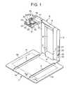
- FIG. 1is a perspective view of a camera stand of a first embodiment according to the present invention when it is in use;
- FIG. 2is a perspective view of first embodiment in a folding state
- FIG. 3is a perspective view of the first embodiment in a folded state
- FIG. 4is an enlarged cross-sectional view taken along a line IV-IV of FIG. 1 ;
- FIG. 5is an enlarged cross-sectional view taken along a line V-V of FIG. 2 ;
- FIG. 6is a perspective view of a turning member and a fixing member of a camera holder of the first embodiment and a digital camera put in a decomposed state;
- FIG. 7is a perspective view of the turning member of the first embodiment as viewed from its bottom side;
- FIG. 8illustrates connection of an electric circuit of the first embodiment to an external device
- FIG. 9is a perspective view of a second embodiment of the camera stand in use.
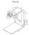
- FIG. 10is a perspective view of the second embodiment in a folding state
- FIG. 11is a perspective view of the second embodiment in a folded state
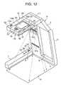
- FIG. 12is a perspective view of a third embodiment of the camera stand in use.
- FIG. 13is a perspective view of the third embodiment in a folding state
- FIG. 14is a perspective view of the third embodiment in a folded state
- FIG. 15is a perspective view of a fourth embodiment of the camera stand in use.
- FIG. 16is a perspective view of the fourth embodiment in a folding state
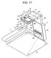
- FIG. 17is a perspective view of a fifth embodiment of the camera stand in use.
- FIG. 18is a perspective view of the fifth embodiment in a folding state
- FIG. 19is a perspective view of the fifth embodiment in a folded state
- FIG. 20is a perspective view of a sixth embodiment of the camera stand in use.
- FIG. 21is a perspective view of a seventh embodiment of the camera stand in use.
- FIGS. 1-8illustrate a first embodiment of a camera stand according to the present invention.
- FIG. 1is a perspective view of the first embodiment in use.
- FIG. 2is a perspective view of the first embodiment in a folding state.
- FIG. 3is a perspective view of the first embodiment in a folded state.
- FIG. 4is an enlarged cross-sectional view taken along a line IV-IV of FIG. 1 .
- FIG. 5is an enlarged cross-sectional view taken along a line V-V of FIG. 2 .
- the camera standcomprises a foot 1 that will be placed, for example on a table as, a rectangular plate-like support 5 that is connected rotatably at a lower semicircular end by a pivot unit 4 to a rear end of the foot 1 and that has a central longitudinal rectangular recess 6 on its front (as viewed in FIG. 1 ), and an arm mechanism 8 .
- the arm mechanismcomprises a hollow rectangular camera holder 10 fixing a commercially available digital camera 30 removably to a forward end thereof and having a width somewhat greater than the camera, and an arm 9 that is connected rotatably at one end to the rear end of the camera holder 10 and supported rotatably at the other end by the other end of the support 5 .
- the arm 5also has a hollow body with a width equal to that of the camera holder 10 .
- the support 5When the camera stand is used, the support 5 is locked in an upstanding state or at a desired forwardly inclined angle to the plate-like foot 1 , the arm 9 is set at an appropriate angle to the support 5 , and the camera holder 10 is likewise set at an appropriate angle to the arm 9 such that the camera 30 can pick up a best image of a picture or document A placed on the foot 1 below the camera.
- the camera 30 , holder 10 and arm 9can be snugly received and arranged longitudinally within the recess 6 in the support 5 , and the support 5 that has received the camera 30 , holder 10 and arm 9 within the recess 6 can then be laid on the foot 1 ( FIGS. 2 and 3 ) to thereby provide a compact block convenient for transportation.
- the foot 1comprises a central rectangular plate 1 a and a pair of side plates 1 b each of which is connected turnably to a respective one of both the sides of the central plate 1 a by a rod-like hinge 2 housed in a cut formed between the central plate 1 a and that side plate in such a manner that two pivots 3 extending outwards axially from each end of the hinge 2 are received in the central plate 1 a and that side plate 1 b through the corresponding cut ends, as shown in FIGS. 4 and 5 .
- Each side plate 1 bhas a width equal to a half of that of the central plate 1 a and a length somewhat shorter than the central plate 1 a .
- Each side plate 1 bcan be extended so as to share the same plane as the central plate 1 a and folded on the central plate.
- the central and side plates 1 a and 1 b of the foot or picture/document rest 1are made of hard plastic and have a thickness of approximately 1-2 mm.
- the hinge 2that has the same thickness as the plates 1 a and 1 b and a width equal to twice that of the thickness of the plates 1 a and 1 b.
- the central plate 1 ahas substantially the same configuration as the support 5 .
- the central plate 1 a and the pair of side plates 1 bhave aligned forward edges.
- the whole document rest 1has a size larger somewhat than an A4-size (210 ⁇ 297 mm) picture/document placed thereon such that the shorter sides of the A4 size are parallel to the rod-like hinges 2 .
- the pivot unit 4 of the support 5is at such a height that the support 5 is folded and laid horizontally just on the pair of side plates 1 b , which have been folded on the central plate 1 a , as shown in FIG. 3 which illustrates the camera stand in non-use or transportation.
- a latch mechanism(not shown) is provided at the end of the arm 9 near the support 5 such that the arm 9 can be locked at a selected one of a plurality of different angles to the support 5 in front of the support 5 or in a state in which the support 5 that completely receives the arm 9 within the recess 6 in the support 5 is laid horizontally on the document rest 1 .
- a second latch(not shown) is provided at the end of the turning member 11 near the arm 9 such that the turning member 11 can be locked at a selected one of a plurality of different angles to the arm 9 or in a state in which the turning member 11 extends in the same direction as the arm 9 .
- FIG. 6is a perspective decomposed view of the turning member 11 and an I-like camera fixing member 12 of the camera holder 10 and the digital camera 30 attachable to the camera holder 10 .
- FIG. 7is a perspective view of the turning member 11 and the arm 9 as viewed from its bottom side.
- the turning member 11 of the camera holder 10comprises a rectangular block having substantially the same width and thickness as the arm 9 and having a central rear protrusion received within a cut formed on a forward end of the arm 9 so as to be rotatable around a pivot (not shown) extending widthwise through the rear protrusion of the turning member 11 and the cut in the forward end of the arm 9 .
- the camera fixing member 12 of the camera holder 10is in the form of an I that has substantially the same width and thickness as the turning member 11 .
- a front end 12 a of the camera fixing member 12is adapted to be fixed to the bottom of the camera 30 by screwing a screw 13 (whose head is shown by 13 a ) through a thinned end part of the fixing member 12 into a tripod attaching screwed hole (not shown) in the bottom of the camera 30 .
- the fixing member 12is also fixed removably by a grooved pin 14 extending from the rear end of the fixing member 12 backward into a hole 15 formed on the front end of the turning member 11 with the aid of a lock mechanism (not shown) that locks the camera fixing member 12 to the front end of turning member 11 .
- An unlock button 16which is pressed to release this locked state is provided on top of the turning member 11 to be.
- the digital camera 30is a commercially available rectangular one that has a body, for example, 87 mm wide, 54 mm high, 22.9 mm thick and that has a zooming image pickup lens 31 adapted to be retracted into the camera body when the power supply is off and extruded from its front when the power supply is on, thereby picking up an image of a picture/document A placed on the foot 1 .
- the camera 30has on its front a strobe light and an auxiliary illumination light (none of them is shown) and on its rear end a monitor display 32 , an optical finder 33 , a mode selector 34 , and a zooming button 35 .
- the camera 30also has on its top a power supply switch 36 , a shutter button 37 and a connector 38 ( FIG. 8 ) through which the camera is connected to an external device such as a (personal) computer.
- a document illumination light 17which comprises an LED (light emitting diode) that illuminates a document A placed on the document rest 1 and a diffuser plate for the light emitted by the LED is provided on a lower surface of the turning member 11 of the camera holder 10 .
- Two finger holes 7are provided on opposite inner sides of the recess 6 in the support 5 at positions near the pivot unit 4 such that the support arm 8 can be raised easily when the camera stand is used, by inserting a user's fingers into the recesses 7 , holding the camera 30 a with the fingers, and then pulling out the camera 30 forward from the holes 6 in the support 5 .
- the support 5has on one side an outside connector 18 that is used to connect the digital camera 30 attached to the camera holder 10 to an external device such as personal computer (not shown), an adapter jack 19 into which an AC adapter 27 ( FIG. 8 ) that converts AC power to DC power is inserted to provide the camera 30 with the DC power, a power key 20 that turns on/off a power supply of the camera 30 , a light key 21 that lights up the picture/document illumination light 17 provided on the lower surface of the turning member 11 of the camera holder 10 .
- the camera fixing member 12 of the camera holder 10has on its front 12 a a male (or female) connector 22 that is fitted into a female (male) connector 38 provided on the bottom of the camera 30 ( FIG. 8 ) for connection to the outside connector 18 .
- the connector 18 provided on the support 5 and the male connector 22 of the camera fixing member 12are connected electrically by a USB (Universal Serial Bus) cable 23 that extends through the support 5 , the arm 9 , the turning member 11 and the fixing member 12 via a separable relay connector 24 provided between the turning member 11 and the fixing member 12 of the camera holder 10 ( FIG. 8 ).
- USBUniversal Serial Bus
- the support 5contains a charging circuit 25 that charges a battery (not shown) of the camera 30 attached to the camera holder 10 , and a light driver 26 for the document illumination light 17 provided on the turning member 11 of the camera holder 10 .
- the charging circuit 25 and the light driver 26are connected to the AC jack 19 .
- the charging circuit 25is connected to the camera connector 22 provided on the camera fixing member 12 over the USB cable 23 and charging leads and terminals (not shown) provided in the relay connector 24 .
- the illumination light driver 26is connected to the document illumination light 17 by leads extending through the support 5 , the arm 9 and the turning member 11 of the camera holder 10 .
- the light driver 26 and the illumination light 17may be connected by the USB cable 23 in place of the connecting leads.
- the power key 20 provided on the support 5is connected to the camera connector 22 through the USB cable 23 , and the camera power supply leads and terminals provided in the relay connector 24 .
- the light key 21is connected to the illumination light driver 26 over leads extending through the support 5 .
- the outside connector 18 provided on the support 5is connected by an external-device connection USB cable 41 to an external device 40 that controls the digital camera 30 and that processes picked-up image data from the digital camera 30 .
- An image based on an image signal sent from the camera 30is displayed on an image display (for example, LCD panel) (not shown) of the external device 40 .
- a projector 42 that enlarges the displayed picture and projects it onto a large screen (not shown)is connected by a control signal cable 43 and an image signal cable 44 to the external device 40 .
- the external device 40comprises, for example, a programmed personal computer that controls the digital camera 30 in accordance with command signals from the projector 42 by operating a control unit (not shown) of the projector 42 or its remote controller 42 a , processes picked-up image data from the digital camera 30 and delivers a resulting image signal to the projector 42 .
- the camera stand of this embodimentexcluding that of the camera 30 is inexpensive due to its simple structure. The user can separate the camera from the stand and use it by itself as the need arises.
- the camera holder 10comprises the turning member 11 provided rotatably at the upper end of the arm 9 , the camera fixing member 12 supporting the camera 30 removably, engaging means (the grooved pin 14 , the pin receiving hole 15 , and the locking mechanism for locking the pin 14 in the hole 15 , and the unlock button 16 ) that fixes the camera fixing member 12 removably to the turning member 11 .
- engaging meansthe grooved pin 14 , the pin receiving hole 15 , and the locking mechanism for locking the pin 14 in the hole 15 , and the unlock button 16
- the use of the fixing member 12 and the screw 13 that is screwed through the fixing member 12 into the tripod screwed hole in the bottom of the camera 30facilitates attachment/removal of the camera 30 to/from the camera fixing member 12 .
- the camera 30can be electrically connected to the external device 40 through the camera stand, and charged using the electric circuit of FIG. 8 .
- the driver 26 for the document illumination light 17 that illuminates the document A placed on the document support 1is provided, the document A, whose image is to be picked up, placed on the picture/document rest 1 can be illumined without consuming the power of the built-in power supply of the camera 30 .
- the document illumination light 17is provided on the turning member 11 of the camera holder 10
- the light 17may be provided on the camera fixing member 12 .
- the light 17 and its driver 26may be connected by the USB cable 23 and the relay connector 24 that connect the outside connector 18 provided on the support 5 and the connector 22 provided on the camera fixing member 12 .
- the document illumination light 17may be provided on the arm 9 of the arm mechanism 8 or the front of the support 5 and not limited to provision on the turning member 11 or the camera fixing member 12 .
- such a light 17may be provided on each of the support 5 and the arm 9 .
- a camera that will be used for such purposemay have such connector on its front, rear or side.
- the USB cable 23is required to be pulled out from the upper end of the support 5 or an appropriate point on the arm 9 or the camera holder 10 and connected at its free end to the camera connector 22 .
- a digital camera other than that adapted for the design of the camera standmay be attached to the camera holder 10 , thereby allowing the camera to pick up an image of the document A.
- the digital cameracan not be received snugly within the recess 6 in the support 5 , the camera is required to be removed from the holder 10 , and then the support arm 9 folded into the recess 6 in the support 5 .
- the pair of side plates 1 b of the document rest 1are illustrated as having the half width of the central plate 1 a , they may have different widths as long as their overall width is equal to, or smaller than, the width of the central plate 1 a for folding purposes.
- the support 5is illustrated as having substantially the same width and length as the central plate 1 a of the document rest 1 , the support 5 may have a different length from the central plate 1 a . In that case, the support 5 can be folded on the central plate 1 a to bring about a compact folded state if the support 5 has substantially the same width as the central plate 1 a.
- FIGS. 9-11illustrate a second embodiment of the camera stand according to the present invention.
- FIG. 9is a perspective view of the camera stand in use.
- FIG. 10is a perspective view of the second embodiment in a folding state.
- FIG. 11is a perspective view of the second embodiment in a folded state.
- the second embodimentis substantially the same in structure, operation and advantage as the first embodiment excluding several points which will be mainly described next and further description of like structural, operational and advantageous points thereof will be omitted.
- the foot or picture/document rest 1 of the camera standwhich will be placed, for example on a table, is in the form of a single rectangular plate somewhat larger than an A4 size and whose rear shorter side is connected rotatably to the lower end of the support 5 in a prior art manner.
- the support 5has a rectangular configuration substantially equal to that of the foot plate 1 .
- a fixing member 52 of the camera holder 10 that receives the camera 30 removably thereincomprises a U-like one that is rotatably supported at its bottom center by a pin 53 extending forwards from the turning member 11 .
- the camera 30can be set at a desired angle to the turning member 11 , for example as shown by a solid or phantom line, such that an image of an object placed under or laterally from the camera can be picked up.
- a document illumination light(not shown) is provided either on a lower surface of the turning member 11 or fixing member 52 .
- itmay be provided on the arm 9 of the arm mechanism 8 , the front of the support 5 or each of the support 5 and the arm 9 .
- the fixing member 52has electric connectors such as shown by 22 and 24 of FIG. 1 for connection to the USB cable 23 and leads to establish an electric circuit such as shown in FIG. 8 in the camera stand of FIG. 9 .
- the support 5is illustrated as having substantially the same size as the picture/document rest 1 , the support 5 may be different in length from the rest 1 . In this case, if the support 5 has substantially the same width as the document rest 1 , the camera stand can be folded into a compact block, as shown in FIG. 11 .
- FIG. 12is a perspective view of a third embodiment of the camera stand in use.
- FIG. 13is a perspective view of the third embodiment in a folding state.
- FIG. 14is a perspective view of the third embodiment in a folded state.
- the third embodimentis substantially the same in structure, operation and advantage as the second embodiment excluding several points, which will be mainly, described next and further description of like structural, operational and advantageous points thereof will be omitted.
- the camera stand of this embodimentcomprises a single hollow square-cross-sectional rod-like foot 1 that will be placed, for example on a table, and that is connected at its rear end portion through a pivot (not shown) extending perpendicular to the foot 1 to a lower side end of the support 5 such that the foot 1 cooperates with the support 5 to support the support 5 rotatably at a desired angle to the horizon.
- the foot 1comprises a hollow substantially the same length as the support 5 .
- the support 5comprises a rectangular plate with a size somewhat lager than an A4 size and a thickness of approximately 35-40 mm that is thicker than the digital camera 30 .
- the support 5has on its front a rectangular recess 6 in a right half thereof that is adapted to receive the arm 9 , the camera holder 10 and the camera 30 a arranged in the same plane.
- the camera standis set such that the camera 30 can pick up a best image of a picture/document A placed downwards by setting the respective optimal angles of the arm 9 , first and second turning members 11 and 65 to the support 5 , the arm 9 , and the first turning member 11 , respectively.
- the camera 30 , the camera holder 10 and the arm 9are arranged in the recess 6 in the support 5 by turning them appropriately and then the support that has received them therein is folded so as to share the same plane with the rod-like foot 1 .
- the camera fixing member 52 of the camera holder 10is in the form of an L of sides 52 a and 52 b that supports the camera 30 on its L-like inner edge.
- the side 67 b of the Lis fixed removably by fixing means such as shown by 14 and 15 in FIG. 6 to the second turning member 65 , which is then supported on the pivot 53 extending forwards from the first turning member 11 .
- Reference numeral 68denotes an unlock button 68 provided on a side of the second turning member 65 for releasing the fixing state of the fixing means.
- a screw whose head 13 a appears partlyis used to fix the side 67 a of the U and the camera as in FIG. 6 .
- two upper and lower document illumination lights 17 a and 17 bare provided sinkably on the front of a left half of the support 5 .
- the connector 18 , AC jack 19 , power key 56 , and light key 57 similar in function to those in the first embodiment ( FIG. 1 )are provided on top of the rod-like foot 1 and not on the support 5 .
- a cable and leads concernedare provided extending through the foot 1 into the body of the camera stand of this embodiment to establish an electric circuit such as shown in FIG. 8 .
- the power key 57is used to turn on/off the document illumination lights 17 a and 17 b.
- the document illumination lightmay be provided on the arm 9 or the camera holder 10 (the first or second turning member 11 or 65 or fixing member 52 ) or each of the support 5 and the arm mechanism 8 .
- a charging circuit and a driversuch as shown by 25 and 26 , respectively, in FIG. 8 are provided in any one of the foot 1 and the support 5 .
- the camera standcan be folded in non-use such that the foot 1 and the support 5 are placed in a stepless flat state, as shown in FIG. 14 .
- the single rod-like foot 1is disposed on one side of the support 5 the foot 1 can cooperate with the support 5 to support the support 5 to a desired angle, for example, to a table in a stabilized manner in use.
- FIGS. 15 and 16illustrate a fourth embodiment of the camera stand of the present invention.
- FIG. 15is a perspective view of the fourth embodiment in use.
- FIG. 16is a perspective view of the fourth embodiment in a folded state.
- the fourth embodimentis substantially the same in structure, operation and advantage as the third embodiment excluding several points that will be mainly described next and further description of like structural, operational and advantageous points thereof will be omitted.
- the digital camera 30is attached rotatably to the camera holder 10 such that the fixing member 52 aligns with the turning member 11 on this side.
- the fixing member 52is in the form an L fixed removably by the screw whose head is shown by 13 a to the camera 30 as in the third embodiment and supported rotatably by the pivot 53 extending forwards from the turning member 11 .
- the support 5is cut on this side thereof such that in non-use the support 5 can receive the arm 9 , the turning member 11 , the fixing member 52 and the camera 30 within the cut 6 in a state in which they are arranged so as to extend in the same direction as the support 5 .
- the whole form of the stand 5 , arm 9 , the fixing member 52 , the turning member 11 and camera 30 arranged sois designed so as to be a rectangle somewhat larger than the A4 size.
- the whole rectanglecan be then folded so as to have the same plane as the rod-like foot 1 , thereby providing a compact block, as shown in FIG. 16 .
- the arm mechanism 8is supported rotatably at its lower end on one side of the upper end of the support 5 in FIG. 15 .
- the document illumination light 17 provided sinkably on the front of the support 5 at an upper positionmay be provided on the arm 9 or camera holder 10 (any one of the turning member 11 and the fixing member 52 ) or each of the support 5 and the arm mechanism 8 .
- the support 5is illustrated as cut on this side thereof, as shown by 6 , so as to receive the arm 9 , the turning member 11 , the fixing member 52 and the camera 30 therein, the support 5 may take the form of a rectangle with an opening for receiving these elements therein.
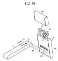
- FIGS. 17-19illustrate a fifth embodiment of the camera stand.
- FIG. 17is a perspective view of the camera stand in use.
- FIG. 18is a perspective view of the camera stand in a folding state.
- FIG. 19is perspective view of the camera stand in a folded state.
- the fifth embodimentis substantially the same in structure, operation and advantage as the third embodiment excluding several points that will be mainly described next and further description of like structural, operational and advantageous points thereof will be omitted.
- the support 5is supported at a lower end rotatably around a pivot 83 extending perpendicular to the rod-like foot 1 from a rear end of the rod-like foot 1 so as to slide along the pivot 83 .
- the support 5comprises a plate-like first support part 5 a with a hollow rectangular cross section, and a second plate-like support part 5 b nestable within the hollow of the first support part 5 a such that the second support part 5 b can be drawn out from the first support part 5 a and locked in use and retracted along with the arm mechanism 8 (including the turning member 11 and the camera holder 10 ) into the first support part 5 a with the camera 30 left outside in non-use.
- the first support part 5 ais approximately 35-40 mm greater than the commercially available camera 30 .
- the camera 30can be covered with a removable cap 95 for protecting purposes, for example in non-use.
- the cap 95has substantially the same thickness as the support 5 .
- the total length of the first support part 5 a and the cap 95 that covers the camera 30 when the second support part 5 b , the arm 11 and the camera holder 10 (including the turning member 65 and the fixing member 52 ) are received within the first support part 5 a with the capped camera left outsideis designed so as to be substantially equal to the length of the rod-like foot 1 .
- a compact block of the camera standis obtained as shown in FIG. 19 .
- the fixing member 52is in the form of an I.
- the unlock button 68 that releases a locked state between the fixing member 52 and the turning member 65 of the camera holder 10is provided on the fixing member 52 .
- the document illumination light 69is provided sinkably on a lower front of the first support part 5 a such that it can emit light obliquely downward onto a picture or document A placed before the light 69 .
- the light 69can be sunk into the front of the first support part 5 a .
- the light 69may be provided on the front of the second support part 5 b , the arm 11 or the camera holder 10 (any one of the turning member 65 and the fixing member 52 ) or each of the second support part 5 b and the arm 11 .
- the camera holder 10 with the camera, the arm 11 and the second support part 5 bare drawn out from the first support part 5 a , and the angles of the camera holder 10 and the arm 11 to the arm 11 and the second support part 5 b , respectively, are then adjusted to support the digital camera 30 at a position distant appropriately upwards from the picture/document so as to read its best image.
- the camera holder 10the arm 11 and the second support part 5 b are received within the first support part 5 a with the camera 30 with the cap left thereon.
- the whole support 5is then drawn laterally to the foot 1 and folded so as to share the same plane as the foot 1 .
- the first support 5 ais supported at its lower end by the pivot 83 of the foot 1 so as to be rotatable around the pivot and slidable along the pivot.
- the whole width of each of the support 5 , the arm 11 and the camera holder 10is reduced compared to the first-fourth embodiments.
- the appearance of the support 5is simplified, thereby providing improved designability since the first support part 5 a receives the second support part 5 b , the arm 9 and the camera holder 10 in the inner space thereof.
- the second support part 5 b , the arm 9 and the camera holder 10are adapted to be received within the first support part 5 a with the capped camera 30 left outside.
- the configuration of the space within the first support part 5 a that receives the second support part 5 b , the arm 9 and the camera holder 10is simplified since a somewhat complicated outer shape of the digital camera 30 need not be taken account of.
- FIG. 20is a perspective view of a sixth embodiment of the camera stand according to the present invention.
- FIG. 21is a perspective view of a seventh embodiment of the camera stand.
- the camera stand of the sixth embodimentcomprises a combination of the fifth embodiment of FIGS. 17-19 and an additional rod-like foot 1 A disposed so as to be symmetrical with the foot 1 with reference to the first support, thereby causing the two rod-like feet 1 and 1 Aa to cooperate to rotatably support the support 8 and hence to increase its stability.
- the pivot 83 acan extend so as to receive an A4 size picture or document between the two feet 1 and 1 A and also retract so as to have a length substantially equal to the width of the support 5 or the arm mechanism 8 .
- FIG. 21is equal in structure to a combination of the third embodiment of FIGS. 12-14 and an additional foot 1 A similar to the corresponding one of FIG. 20 except that the camera fixing member 52 is of an I-like one and that no turning member such as shown by 65 in FIGS. 12-14 is used.
- the digital camera 30is illustrated as attached to the L-like fixing member 52 in the third embodiment of FIGS. 12-14 mentioned above such that the shutter button 37 appears on this side of the camera 30 while the camera 30 is attached to the I-like fixing member 52 in the camera stand of the seventh embodiment such that the shutter button 37 appears on the front end of the camera.
- the camera standmay have an additional foot such as shown by 1 A in FIG. 21 such that both the feet 1 and 1 A cooperate to support the support 5 rotatably at its lower end for improving stability of the camera stand.
- the folding or single flat foot plate 1may be replaced with one or two rod-like feet shown by 1 or 1 A.
- the rod-like feet 1 and 1 Amay be replaced with a picture/document rest such as shown in FIG. 1 .
Landscapes
- Engineering & Computer Science (AREA)
- General Engineering & Computer Science (AREA)
- Mechanical Engineering (AREA)
- Multimedia (AREA)
- Signal Processing (AREA)
- Accessories Of Cameras (AREA)
- Studio Devices (AREA)
- Blocking Light For Cameras (AREA)
Abstract
Description
- a foot that will be placed a surface;
- a support with opposite ends at one of which the support is supported rotatably on the foot and turnable between a lying position and an upstanding position;
- an arm mechanism with opposite ends at one of which the arm mechanism is capable of attaching a digital camera removably thereto and supported rotatably at the other end to the other end of the support such that in use the arm mechanism is adjusted in angle to the support so as to allow the camera to pick up an image of a picture/document placed under the camera while in non-use the arm mechanism is received within the confine of the support, which is then folded on the foot.
Claims (19)
Applications Claiming Priority (4)
| Application Number | Priority Date | Filing Date | Title |
|---|---|---|---|
| JP2003-298844 | 2003-08-22 | ||
| JP2003298844 | 2003-08-22 | ||
| JP2004175716AJP3941799B2 (en) | 2003-08-22 | 2004-06-14 | Camera stand |
| JP2004-175716 | 2004-06-14 |
Publications (2)
| Publication Number | Publication Date |
|---|---|
| US20050040298A1 US20050040298A1 (en) | 2005-02-24 |
| US7626634B2true US7626634B2 (en) | 2009-12-01 |
Family
ID=34197184
Family Applications (1)
| Application Number | Title | Priority Date | Filing Date |
|---|---|---|---|
| US10/922,277Expired - Fee RelatedUS7626634B2 (en) | 2003-08-22 | 2004-08-19 | Camera stand with camera charging mechanism |
Country Status (3)
| Country | Link |
|---|---|
| US (1) | US7626634B2 (en) |
| JP (1) | JP3941799B2 (en) |
| CN (1) | CN100504571C (en) |
Cited By (33)
| Publication number | Priority date | Publication date | Assignee | Title |
|---|---|---|---|---|
| US20070082326A1 (en)* | 2005-10-07 | 2007-04-12 | Matthew Nuffort | Imaging mechanism for wireless handheld devices, portable digital assistants, and other handheld computing devices |
| US20100054721A1 (en)* | 2008-09-04 | 2010-03-04 | Quanta Computer Inc. | Document snapshot device |
| US20100134635A1 (en)* | 2008-12-01 | 2010-06-03 | Tandberg Telecom As | Portable video conference camera |
| US20100237222A1 (en)* | 2009-03-21 | 2010-09-23 | Chi Mei Communication Systems, Inc. | Accessory structure for portable electronic devices |
| US20100289903A1 (en)* | 2009-05-12 | 2010-11-18 | Fitzroy Farquharson | Portable presentation computer station |
| US20120050543A1 (en)* | 2010-08-30 | 2012-03-01 | Gianluca Colla | Method and apparatus for measuring the focus performance of a camera and lens combination |
| US20120120463A1 (en)* | 2010-06-11 | 2012-05-17 | Hu Yulun | Scanner |
| US20120293692A1 (en)* | 2011-05-20 | 2012-11-22 | Kenji Namie | Apparatus, method, and system of image processing, and recording medium storing image processing control program |
| US20130021523A1 (en)* | 2011-07-18 | 2013-01-24 | Hon Hai Precision Industry Co., Ltd. | Electronic apparatus with stand mechanism for magnification function |
| US20130215282A1 (en)* | 2012-02-21 | 2013-08-22 | M-Vision Co., Ltd. | Examining apparatus and method for machine vision system |
| USD699242S1 (en)* | 2012-01-26 | 2014-02-11 | Yulun HU | Scanner |
| US8681268B2 (en)* | 2012-05-24 | 2014-03-25 | Abisee, Inc. | Vision assistive devices and user interfaces |
| US20140160345A1 (en)* | 2012-12-07 | 2014-06-12 | Pfu Limited | Lighting device and image capturing system |
| USD714775S1 (en)* | 2013-10-24 | 2014-10-07 | Samsung Electronics Co., Ltd. | Supporter for portable terminal |
| USD716787S1 (en)* | 2013-10-31 | 2014-11-04 | Pfu Limited | Smart phone stand with communication and lamp function |
| USD717289S1 (en)* | 2013-10-31 | 2014-11-11 | Pfu Limited | Smart phone stand with communication and lamp function |
| USD717308S1 (en)* | 2012-11-01 | 2014-11-11 | Target Brands, Inc. | Stand |
| USD723024S1 (en)* | 2013-10-24 | 2015-02-24 | Samsung Electronics Co., Ltd. | Supporter for portable terminal |
| US20150117849A1 (en)* | 2013-10-31 | 2015-04-30 | Pfu Limited | Lighting device, image capturing system, and lighting control method |
| USD753643S1 (en)* | 2014-05-09 | 2016-04-12 | Samsung Electronics Co., Ltd. | Electronic device holder |
| USD753642S1 (en)* | 2014-03-07 | 2016-04-12 | Pfu Limited | Smart phone stand with communication and lamp function |
| US9325909B2 (en) | 2012-12-17 | 2016-04-26 | Pfu Limited | Image capturing system having a virtual switch on a surface of a base of a mounting stand |
| USD756346S1 (en)* | 2014-12-24 | 2016-05-17 | Spigen Korea Co., Ltd. | Smartphone mount for vehicles |
| US20170090272A1 (en)* | 2015-05-12 | 2017-03-30 | Muneer Ayaad | Foldable camera and projector with code activated controls |
| US9829183B2 (en) | 2014-10-28 | 2017-11-28 | Franklin And Marshall College | Portable copystand for enhancing ink/parchment contrast |
| USD822581S1 (en) | 2017-05-16 | 2018-07-10 | Spigen Korea Co., Ltd. | Electronic device mount for vehicles |
| US10298851B2 (en)* | 2016-10-26 | 2019-05-21 | C & P Co., Ltd. | Portable device for magnifying electronic image |
| US20190178438A1 (en)* | 2017-12-07 | 2019-06-13 | Nite Ize, Inc. | Systems and methods for a flipout phone holder and stand |
| US10728406B1 (en)* | 2019-03-08 | 2020-07-28 | Foxlink Image Technology Co., Ltd. | Holding device for mobile device |
| US10971033B2 (en) | 2019-02-07 | 2021-04-06 | Freedom Scientific, Inc. | Vision assistive device with extended depth of field |
| US11320723B2 (en)* | 2017-09-11 | 2022-05-03 | Hewlett-Packard Development Company, L.P. | Scanning of objects |
| US11532216B2 (en) | 2018-09-07 | 2022-12-20 | Signalisation D'urgence Rh Inc. | Collapsible warning device and method for emitting a light signal |
| US11533405B1 (en)* | 2021-08-23 | 2022-12-20 | Fujifilm Business Innovation Corp. | Reading device and image forming apparatus |
Families Citing this family (49)
| Publication number | Priority date | Publication date | Assignee | Title |
|---|---|---|---|---|
| TWI225979B (en)* | 2003-09-25 | 2005-01-01 | Aopen Inc | Computer with multiple operation modes |
| EP1745454A1 (en)* | 2004-04-13 | 2007-01-24 | Pulse Data International Limited | Image magnifier for the visually impaired |
| JP4708095B2 (en)* | 2005-06-08 | 2011-06-22 | 富士フイルム株式会社 | Document presentation device |
| US7980708B2 (en) | 2005-06-08 | 2011-07-19 | Fujinon Corporation | Document presentation device including a movable part |
| JP4718997B2 (en)* | 2005-12-27 | 2011-07-06 | 株式会社エルモ社 | Document presentation device |
| TWM330797U (en) | 2007-08-30 | 2008-04-21 | Aiptek Int Inc | Digital photo frame having photographing function |
| US8035737B2 (en)* | 2008-11-26 | 2011-10-11 | Crs Electronic Co., Ltd. | Foldable picture-taking device with scanning function |
| CN101854449A (en)* | 2009-04-01 | 2010-10-06 | 鸿富锦精密工业(深圳)有限公司 | Digital Photo Frames |
| CN101854450A (en)* | 2009-04-03 | 2010-10-06 | 鸿富锦精密工业(深圳)有限公司 | Image acquisition device |
| CN101929838B (en)* | 2009-06-26 | 2012-09-19 | 鸿富锦精密工业(深圳)有限公司 | Bracket and image measuring device using the same |
| JP2011119954A (en)* | 2009-12-03 | 2011-06-16 | Elmo Co Ltd | Document presenter |
| CN102156377A (en)* | 2010-05-18 | 2011-08-17 | 兰州理工大学 | Camera support using digital camera as scanner |
| CN102253575B (en)* | 2010-05-19 | 2014-12-10 | 万里科技股份有限公司 | camera arm |
| KR101148105B1 (en)* | 2010-09-15 | 2012-05-23 | 주식회사 제이투와이코리아 | Portable Device for Transmitting Images |
| CN102131022B (en)* | 2011-01-05 | 2014-09-24 | 王彤 | Double-lens file shooting instrument |
| JP2012195877A (en)* | 2011-03-17 | 2012-10-11 | Seiko Epson Corp | Image output device |
| JP4991017B1 (en)* | 2011-09-15 | 2012-08-01 | パナソニック株式会社 | Image reading device |
| JP2013121051A (en)* | 2011-12-07 | 2013-06-17 | Elmo Co Ltd | Material presentation device |
| TW201351016A (en)* | 2012-06-08 | 2013-12-16 | Hon Hai Prec Ind Co Ltd | Projection device |
| WO2014003767A1 (en)* | 2012-06-28 | 2014-01-03 | Landa Pedro | An image capture device foldable stand |
| US9794520B2 (en) | 2012-09-05 | 2017-10-17 | Pioneer Corporation | Image capture device and method for recognizing irradiated position mark on object |
| US20150252936A1 (en)* | 2012-09-07 | 2015-09-10 | Christian Krantz | Device for holding a sheet of paper, a holder for a mobile device and software program for use with such holder |
| JP6007091B2 (en)* | 2012-12-07 | 2016-10-12 | 株式会社Pfu | Imaging platform and imaging system |
| US8781311B1 (en)* | 2013-02-02 | 2014-07-15 | Cssn Inc. | Document holder for a portable imaging apparatus |
| CN103070663B (en)* | 2013-02-21 | 2015-03-25 | 谢晓秋 | Auxiliary intraoral photographing bracket for oral major |
| CN105282370A (en)* | 2013-04-25 | 2016-01-27 | 胡妍 | Miniature scanner with illuminating lamp |
| US9195265B1 (en)* | 2013-05-24 | 2015-11-24 | Tyrone D. Jackson | Multi-function attachment for a mobile computer |
| WO2015039297A1 (en)* | 2013-09-18 | 2015-03-26 | 庄新宏 | Book copying device |
| CN103873732A (en)* | 2014-03-28 | 2014-06-18 | 深圳市神州海纳科技有限公司 | Handheld type certificate image collecting device |
| WO2016205140A1 (en)* | 2015-06-13 | 2016-12-22 | Google Inc. | Camera stand having multiple degrees of freedom of motion |
| CN104915043A (en)* | 2015-07-08 | 2015-09-16 | 刘贝 | Mouse pad with functions of high-speed photographing instrument |
| US9362969B1 (en)* | 2015-10-23 | 2016-06-07 | C1 Bank | Electronic device stand for image acquisition and analysis |
| JP6664277B2 (en)* | 2016-05-25 | 2020-03-13 | 株式会社エルモ社 | Document camera |
| JP6590685B2 (en)* | 2015-12-22 | 2019-10-16 | 株式会社エルモ社 | Document camera |
| US9880450B2 (en)* | 2015-12-22 | 2018-01-30 | Elmo Co., Ltd. | Document camera |
| JP6570180B2 (en)* | 2015-12-22 | 2019-09-04 | 株式会社エルモ社 | Document camera |
| JP6148746B1 (en)* | 2016-02-12 | 2017-06-14 | 株式会社Pfu | Image reading device and image reading auxiliary device |
| CN107344459A (en)* | 2016-05-06 | 2017-11-14 | 力山工业股份有限公司 | Multifunctional carrying platform |
| US20190092078A1 (en)* | 2017-09-26 | 2019-03-28 | Casio Computer Co., Ltd. | Apparatus for turning pages of a book and accommodation method for same |
| JP2019061055A (en)* | 2017-09-26 | 2019-04-18 | キヤノン株式会社 | Imaging device |
| EP3496072B1 (en)* | 2017-12-08 | 2024-12-04 | Optelec Holding B.V. | Viewing device for sight-impaired users |
| US20200012314A1 (en)* | 2018-01-25 | 2020-01-09 | Shun Chang | Portable stand for electronic device |
| JP7029672B2 (en)* | 2018-05-08 | 2022-03-04 | 中国電力株式会社 | Portable shooting device |
| US10653032B2 (en)* | 2018-05-21 | 2020-05-12 | James Huffaker | Tablet computer positioning assembly |
| CN111386420B (en)* | 2019-04-26 | 2022-02-15 | 深圳市大疆创新科技有限公司 | Remote controller support and remote controller |
| US11106117B2 (en)* | 2019-10-04 | 2021-08-31 | Ipevo, Inc. | Foldable camera stand |
| CN111928069A (en)* | 2020-07-24 | 2020-11-13 | 四川科华天府科技有限公司 | Multi-angle real object exhibition stand |
| CN112303413B (en)* | 2020-11-02 | 2022-04-12 | 山东女子学院 | Digital media movie & TV equipment |
| JP2023143212A (en)* | 2022-03-25 | 2023-10-06 | 富士フイルムビジネスイノベーション株式会社 | Image reading device, and image forming apparatus |
Citations (14)
| Publication number | Priority date | Publication date | Assignee | Title |
|---|---|---|---|---|
| JPS63254868A (en) | 1987-04-13 | 1988-10-21 | Canon Inc | image input device |
| US5374971A (en)* | 1993-03-12 | 1994-12-20 | Picturetel Corporation | Two-view video camera stand and support method |
| US5444486A (en)* | 1992-03-30 | 1995-08-22 | Elmo Co., Ltd. | Portable image input equipment |
| JPH0884276A (en) | 1994-09-12 | 1996-03-26 | Canon Inc | Image input device |
| JPH08111803A (en) | 1994-10-07 | 1996-04-30 | Canon Inc | Image input device |
| US5767905A (en)* | 1996-04-05 | 1998-06-16 | Archambo; Michael | Video camera periscope and monitor surveying devices for the handicapped |
| US6008846A (en)* | 1994-10-07 | 1999-12-28 | Canon Kabushiki Kaisha | Document sensing apparatus |
| JP2000032315A (en) | 1998-07-09 | 2000-01-28 | Canon Inc | Image input / output device |
| JP2001069381A (en) | 1999-08-25 | 2001-03-16 | Fujitsu General Ltd | Surveillance camera lens cover |
| JP2001144997A (en) | 1999-11-16 | 2001-05-25 | Minolta Co Ltd | Camera connector and image pickup system |
| JP2002281349A (en) | 2001-03-14 | 2002-09-27 | Canon Inc | Document camera |
| JP2003179782A (en) | 2001-12-12 | 2003-06-27 | Canon Inc | Document camera |
| US20030133013A1 (en)* | 2002-01-15 | 2003-07-17 | Elmo Company, Limited | Imaging apparatus |
| US7050106B2 (en)* | 2001-11-21 | 2006-05-23 | Canon Kabushiki Kaisha | Image input device with rotatable image pickup unit |
- 2004
- 2004-06-14JPJP2004175716Apatent/JP3941799B2/ennot_activeExpired - Lifetime
- 2004-08-19USUS10/922,277patent/US7626634B2/ennot_activeExpired - Fee Related
- 2004-08-23CNCNB2004100572350Apatent/CN100504571C/ennot_activeExpired - Fee Related
Patent Citations (16)
| Publication number | Priority date | Publication date | Assignee | Title |
|---|---|---|---|---|
| JPS63254868A (en) | 1987-04-13 | 1988-10-21 | Canon Inc | image input device |
| US5444486A (en)* | 1992-03-30 | 1995-08-22 | Elmo Co., Ltd. | Portable image input equipment |
| US5374971A (en)* | 1993-03-12 | 1994-12-20 | Picturetel Corporation | Two-view video camera stand and support method |
| JPH0884276A (en) | 1994-09-12 | 1996-03-26 | Canon Inc | Image input device |
| JPH08111803A (en) | 1994-10-07 | 1996-04-30 | Canon Inc | Image input device |
| US6008846A (en)* | 1994-10-07 | 1999-12-28 | Canon Kabushiki Kaisha | Document sensing apparatus |
| US5767905A (en)* | 1996-04-05 | 1998-06-16 | Archambo; Michael | Video camera periscope and monitor surveying devices for the handicapped |
| JP2000032315A (en) | 1998-07-09 | 2000-01-28 | Canon Inc | Image input / output device |
| JP2001069381A (en) | 1999-08-25 | 2001-03-16 | Fujitsu General Ltd | Surveillance camera lens cover |
| JP2001144997A (en) | 1999-11-16 | 2001-05-25 | Minolta Co Ltd | Camera connector and image pickup system |
| JP2002281349A (en) | 2001-03-14 | 2002-09-27 | Canon Inc | Document camera |
| US7050106B2 (en)* | 2001-11-21 | 2006-05-23 | Canon Kabushiki Kaisha | Image input device with rotatable image pickup unit |
| JP2003179782A (en) | 2001-12-12 | 2003-06-27 | Canon Inc | Document camera |
| US20030133013A1 (en)* | 2002-01-15 | 2003-07-17 | Elmo Company, Limited | Imaging apparatus |
| JP2003209717A (en) | 2002-01-15 | 2003-07-25 | Elmo Co Ltd | Imaging device |
| CN1432861A (en) | 2002-01-15 | 2003-07-30 | 爱而慕株式会社 | Video camera |
Cited By (44)
| Publication number | Priority date | Publication date | Assignee | Title |
|---|---|---|---|---|
| US20070082326A1 (en)* | 2005-10-07 | 2007-04-12 | Matthew Nuffort | Imaging mechanism for wireless handheld devices, portable digital assistants, and other handheld computing devices |
| US20100054721A1 (en)* | 2008-09-04 | 2010-03-04 | Quanta Computer Inc. | Document snapshot device |
| US7899310B2 (en)* | 2008-09-04 | 2011-03-01 | Quanta Computer Inc. | Document snapshot device |
| US20100134635A1 (en)* | 2008-12-01 | 2010-06-03 | Tandberg Telecom As | Portable video conference camera |
| US8233081B2 (en)* | 2008-12-01 | 2012-07-31 | Cisco Technology, Inc. | Portable video conference camera |
| US20100237222A1 (en)* | 2009-03-21 | 2010-09-23 | Chi Mei Communication Systems, Inc. | Accessory structure for portable electronic devices |
| US8077860B2 (en)* | 2009-03-21 | 2011-12-13 | Chi Mei Communication Systems, Inc. | Accessory structure for portable electronic devices |
| US20100289903A1 (en)* | 2009-05-12 | 2010-11-18 | Fitzroy Farquharson | Portable presentation computer station |
| US20120120463A1 (en)* | 2010-06-11 | 2012-05-17 | Hu Yulun | Scanner |
| US20120050543A1 (en)* | 2010-08-30 | 2012-03-01 | Gianluca Colla | Method and apparatus for measuring the focus performance of a camera and lens combination |
| US8581986B2 (en)* | 2010-08-30 | 2013-11-12 | Datacolor Holding Ag | Method and apparatus for measuring the focus performance of a camera and lens combination |
| US20120293692A1 (en)* | 2011-05-20 | 2012-11-22 | Kenji Namie | Apparatus, method, and system of image processing, and recording medium storing image processing control program |
| US8605174B2 (en)* | 2011-05-20 | 2013-12-10 | Ricoh Company, Ltd. | Apparatus, method, and system of image processing, and recording medium storing image processing control program |
| US20130021523A1 (en)* | 2011-07-18 | 2013-01-24 | Hon Hai Precision Industry Co., Ltd. | Electronic apparatus with stand mechanism for magnification function |
| US8605214B2 (en)* | 2011-07-18 | 2013-12-10 | Hon Hai Precision Industry Co., Ltd. | Electronic apparatus with stand mechanism for magnification function |
| USD699242S1 (en)* | 2012-01-26 | 2014-02-11 | Yulun HU | Scanner |
| US20130215282A1 (en)* | 2012-02-21 | 2013-08-22 | M-Vision Co., Ltd. | Examining apparatus and method for machine vision system |
| US8681268B2 (en)* | 2012-05-24 | 2014-03-25 | Abisee, Inc. | Vision assistive devices and user interfaces |
| US9449531B2 (en) | 2012-05-24 | 2016-09-20 | Freedom Scientific, Inc. | Vision assistive devices and user interfaces |
| USD717308S1 (en)* | 2012-11-01 | 2014-11-11 | Target Brands, Inc. | Stand |
| US20140160345A1 (en)* | 2012-12-07 | 2014-06-12 | Pfu Limited | Lighting device and image capturing system |
| US9491344B2 (en)* | 2012-12-07 | 2016-11-08 | Pfu Limited | Lighting device and image capturing system |
| US9325909B2 (en) | 2012-12-17 | 2016-04-26 | Pfu Limited | Image capturing system having a virtual switch on a surface of a base of a mounting stand |
| USD714775S1 (en)* | 2013-10-24 | 2014-10-07 | Samsung Electronics Co., Ltd. | Supporter for portable terminal |
| USD723024S1 (en)* | 2013-10-24 | 2015-02-24 | Samsung Electronics Co., Ltd. | Supporter for portable terminal |
| USD717289S1 (en)* | 2013-10-31 | 2014-11-11 | Pfu Limited | Smart phone stand with communication and lamp function |
| US20150117849A1 (en)* | 2013-10-31 | 2015-04-30 | Pfu Limited | Lighting device, image capturing system, and lighting control method |
| US9280036B2 (en)* | 2013-10-31 | 2016-03-08 | Pfu Limited | Lighting device, image capturing system, and lighting control method |
| USD716787S1 (en)* | 2013-10-31 | 2014-11-04 | Pfu Limited | Smart phone stand with communication and lamp function |
| USD753642S1 (en)* | 2014-03-07 | 2016-04-12 | Pfu Limited | Smart phone stand with communication and lamp function |
| USD753643S1 (en)* | 2014-05-09 | 2016-04-12 | Samsung Electronics Co., Ltd. | Electronic device holder |
| US9829183B2 (en) | 2014-10-28 | 2017-11-28 | Franklin And Marshall College | Portable copystand for enhancing ink/parchment contrast |
| USD756346S1 (en)* | 2014-12-24 | 2016-05-17 | Spigen Korea Co., Ltd. | Smartphone mount for vehicles |
| US20170090272A1 (en)* | 2015-05-12 | 2017-03-30 | Muneer Ayaad | Foldable camera and projector with code activated controls |
| US10298851B2 (en)* | 2016-10-26 | 2019-05-21 | C & P Co., Ltd. | Portable device for magnifying electronic image |
| USD822581S1 (en) | 2017-05-16 | 2018-07-10 | Spigen Korea Co., Ltd. | Electronic device mount for vehicles |
| US11320723B2 (en)* | 2017-09-11 | 2022-05-03 | Hewlett-Packard Development Company, L.P. | Scanning of objects |
| US20190178438A1 (en)* | 2017-12-07 | 2019-06-13 | Nite Ize, Inc. | Systems and methods for a flipout phone holder and stand |
| US10837595B2 (en)* | 2017-12-07 | 2020-11-17 | Nite Ize, Inc. | Systems and methods for a flipout phone holder and stand |
| US11532216B2 (en) | 2018-09-07 | 2022-12-20 | Signalisation D'urgence Rh Inc. | Collapsible warning device and method for emitting a light signal |
| US10971033B2 (en) | 2019-02-07 | 2021-04-06 | Freedom Scientific, Inc. | Vision assistive device with extended depth of field |
| US12159548B2 (en) | 2019-02-07 | 2024-12-03 | Freedom Scientific, Inc. | Vision assistive device with extended depth of field |
| US10728406B1 (en)* | 2019-03-08 | 2020-07-28 | Foxlink Image Technology Co., Ltd. | Holding device for mobile device |
| US11533405B1 (en)* | 2021-08-23 | 2022-12-20 | Fujifilm Business Innovation Corp. | Reading device and image forming apparatus |
Also Published As
| Publication number | Publication date |
|---|---|
| CN100504571C (en) | 2009-06-24 |
| JP2005099708A (en) | 2005-04-14 |
| JP3941799B2 (en) | 2007-07-04 |
| US20050040298A1 (en) | 2005-02-24 |
| CN1584728A (en) | 2005-02-23 |
Similar Documents
| Publication | Publication Date | Title |
|---|---|---|
| US7626634B2 (en) | Camera stand with camera charging mechanism | |
| US7551225B2 (en) | Positioning accessory for camera-equipped wireless terminals | |
| US8284543B2 (en) | Structure of keyboard combinable with electronic device | |
| US7929050B2 (en) | Document camera | |
| US7706673B1 (en) | Portable remote camera control device | |
| US5444486A (en) | Portable image input equipment | |
| CN207198533U (en) | Connection component and self-shooting bar, filming apparatus for fixed camera | |
| EP0449657A1 (en) | Video camera | |
| EP0530079A2 (en) | Device for charging camera batteries and for connecting a video camera with other electric devices | |
| KR20050036745A (en) | Document camera and document camera system | |
| CN204554316U (en) | Band flash of light multifunctional foldable self-shooting bar | |
| WO2019052009A1 (en) | Selfie stick, pan-tilt camera, and photography device | |
| JP2006058663A (en) | Camera stand | |
| CN108495015B (en) | Shooting device and electronic equipment | |
| JP2003298249A (en) | Electronic device table | |
| CN212060835U (en) | Light filling lamp with wireless charging function | |
| JP5187302B2 (en) | Camera stand | |
| US5226708A (en) | Lighting device for use with video camera | |
| JPH0630311A (en) | Fold type image pickup device | |
| JPH0751814Y2 (en) | Handle mounting structure | |
| US20060217163A1 (en) | Cradle for portable device | |
| US20040081422A1 (en) | Display-provided portable electronic device | |
| JP2005318023A (en) | Electronic camera device, imaging method and program | |
| JPH0535655Y2 (en) | ||
| JP2003241851A (en) | Connecting base for small information equipment |
Legal Events
| Date | Code | Title | Description |
|---|---|---|---|
| AS | Assignment | Owner name:CASIO COMPUTER CO., LTD., JAPAN Free format text:ASSIGNMENT OF ASSIGNORS INTEREST;ASSIGNORS:OHKI, YUJI;SHIGEMURA, ATSUSHI;IWAMOTO, MASAKAZU;AND OTHERS;REEL/FRAME:015714/0216 Effective date:20040816 | |
| FEPP | Fee payment procedure | Free format text:PAYOR NUMBER ASSIGNED (ORIGINAL EVENT CODE: ASPN); ENTITY STATUS OF PATENT OWNER: LARGE ENTITY | |
| STCF | Information on status: patent grant | Free format text:PATENTED CASE | |
| CC | Certificate of correction | ||
| FPAY | Fee payment | Year of fee payment:4 | |
| FEPP | Fee payment procedure | Free format text:PAYOR NUMBER ASSIGNED (ORIGINAL EVENT CODE: ASPN); ENTITY STATUS OF PATENT OWNER: LARGE ENTITY Free format text:PAYER NUMBER DE-ASSIGNED (ORIGINAL EVENT CODE: RMPN); ENTITY STATUS OF PATENT OWNER: LARGE ENTITY | |
| FPAY | Fee payment | Year of fee payment:8 | |
| FEPP | Fee payment procedure | Free format text:MAINTENANCE FEE REMINDER MAILED (ORIGINAL EVENT CODE: REM.); ENTITY STATUS OF PATENT OWNER: LARGE ENTITY | |
| LAPS | Lapse for failure to pay maintenance fees | Free format text:PATENT EXPIRED FOR FAILURE TO PAY MAINTENANCE FEES (ORIGINAL EVENT CODE: EXP.); ENTITY STATUS OF PATENT OWNER: LARGE ENTITY | |
| STCH | Information on status: patent discontinuation | Free format text:PATENT EXPIRED DUE TO NONPAYMENT OF MAINTENANCE FEES UNDER 37 CFR 1.362 | |
| FP | Lapsed due to failure to pay maintenance fee | Effective date:20211201 |