US7625378B2 - Devices and methods for securing a bone plate to a bony segment - Google Patents
Devices and methods for securing a bone plate to a bony segmentDownload PDFInfo
- Publication number
- US7625378B2 US7625378B2US10/261,120US26112002AUS7625378B2US 7625378 B2US7625378 B2US 7625378B2US 26112002 AUS26112002 AUS 26112002AUS 7625378 B2US7625378 B2US 7625378B2
- Authority
- US
- United States
- Prior art keywords
- extension
- guide tube
- plate
- passage
- guide
- Prior art date
- Legal status (The legal status is an assumption and is not a legal conclusion. Google has not performed a legal analysis and makes no representation as to the accuracy of the status listed.)
- Expired - Fee Related, expires
Links
- 210000000988bone and boneAnatomy0.000titleclaimsabstractdescription72
- 238000000034methodMethods0.000titledescription8
- 239000007943implantSubstances0.000claimsdescription9
- 239000000463materialSubstances0.000claimsdescription8
- 230000008468bone growthEffects0.000claimsdescription3
- 238000004891communicationMethods0.000claimsdescription3
- 230000000149penetrating effectEffects0.000claims2
- 238000005553drillingMethods0.000description6
- 238000010079rubber tappingMethods0.000description6
- 230000000712assemblyEffects0.000description4
- 238000000429assemblyMethods0.000description4
- 230000004927fusionEffects0.000description4
- 239000000203mixtureSubstances0.000description3
- 238000007747platingMethods0.000description3
- 102100033337PDZ and LIM domain protein 7Human genes0.000description2
- 101710121660PDZ and LIM domain protein 7Proteins0.000description2
- 239000003462bioceramicSubstances0.000description2
- 239000000969carrierSubstances0.000description2
- 239000012876carrier materialSubstances0.000description2
- 208000014674injuryDiseases0.000description2
- 238000003780insertionMethods0.000description2
- 230000037431insertionEffects0.000description2
- 238000012986modificationMethods0.000description2
- 230000004048modificationEffects0.000description2
- 230000002642osteogeneic effectEffects0.000description2
- 230000007170pathologyEffects0.000description2
- 230000035515penetrationEffects0.000description2
- 210000000115thoracic cavityAnatomy0.000description2
- 230000008733traumaEffects0.000description2
- 102000007350Bone Morphogenetic ProteinsHuman genes0.000description1
- 108010007726Bone Morphogenetic ProteinsProteins0.000description1
- 102000008186CollagenHuman genes0.000description1
- 108010035532CollagenProteins0.000description1
- 102000018233Fibroblast Growth FactorHuman genes0.000description1
- 108050007372Fibroblast Growth FactorProteins0.000description1
- 206010027677Fractures and dislocationsDiseases0.000description1
- 101000599951Homo sapiens Insulin-like growth factor IProteins0.000description1
- 102100037852Insulin-like growth factor IHuman genes0.000description1
- 206010028980NeoplasmDiseases0.000description1
- 102000010780Platelet-Derived Growth FactorHuman genes0.000description1
- 108010038512Platelet-Derived Growth FactorProteins0.000description1
- 102000046299Transforming Growth Factor beta1Human genes0.000description1
- 101800002279Transforming growth factor beta-1Proteins0.000description1
- 230000004075alterationEffects0.000description1
- 239000005312bioglassSubstances0.000description1
- 229940112869bone morphogenetic proteinDrugs0.000description1
- 229910000389calcium phosphateInorganic materials0.000description1
- 239000001506calcium phosphateSubstances0.000description1
- 235000011010calcium phosphatesNutrition0.000description1
- 239000003795chemical substances by applicationSubstances0.000description1
- 229920001436collagenPolymers0.000description1
- 230000006835compressionEffects0.000description1
- 238000007906compressionMethods0.000description1
- 230000007547defectEffects0.000description1
- 230000000694effectsEffects0.000description1
- 229940126864fibroblast growth factorDrugs0.000description1
- 229910052588hydroxylapatiteInorganic materials0.000description1
- 208000015181infectious diseaseDiseases0.000description1
- 238000012423maintenanceMethods0.000description1
- 208000015122neurodegenerative diseaseDiseases0.000description1
- 230000002188osteogenic effectEffects0.000description1
- 230000002138osteoinductive effectEffects0.000description1
- XYJRXVWERLGGKC-UHFFFAOYSA-Dpentacalcium;hydroxide;triphosphateChemical compound[OH-].[Ca+2].[Ca+2].[Ca+2].[Ca+2].[Ca+2].[O-]P([O-])([O-])=O.[O-]P([O-])([O-])=O.[O-]P([O-])([O-])=OXYJRXVWERLGGKC-UHFFFAOYSA-D0.000description1
- 229920000642polymerPolymers0.000description1
- 238000002360preparation methodMethods0.000description1
- 230000001737promoting effectEffects0.000description1
- 230000006641stabilisationEffects0.000description1
- 238000011105stabilizationMethods0.000description1
- 238000001356surgical procedureMethods0.000description1
- 230000001225therapeutic effectEffects0.000description1
- 229940099456transforming growth factor beta 1Drugs0.000description1
- QORWJWZARLRLPR-UHFFFAOYSA-Htricalcium bis(phosphate)Chemical compound[Ca+2].[Ca+2].[Ca+2].[O-]P([O-])([O-])=O.[O-]P([O-])([O-])=OQORWJWZARLRLPR-UHFFFAOYSA-H0.000description1
Images


Classifications
- A—HUMAN NECESSITIES
- A61—MEDICAL OR VETERINARY SCIENCE; HYGIENE
- A61B—DIAGNOSIS; SURGERY; IDENTIFICATION
- A61B17/00—Surgical instruments, devices or methods
- A61B17/16—Instruments for performing osteoclasis; Drills or chisels for bones; Trepans
- A61B17/17—Guides or aligning means for drills, mills, pins or wires
- A61B17/1728—Guides or aligning means for drills, mills, pins or wires for holes for bone plates or plate screws
- A—HUMAN NECESSITIES
- A61—MEDICAL OR VETERINARY SCIENCE; HYGIENE
- A61B—DIAGNOSIS; SURGERY; IDENTIFICATION
- A61B17/00—Surgical instruments, devices or methods
- A61B17/16—Instruments for performing osteoclasis; Drills or chisels for bones; Trepans
- A61B17/17—Guides or aligning means for drills, mills, pins or wires
- A61B17/1739—Guides or aligning means for drills, mills, pins or wires specially adapted for particular parts of the body
- A61B17/1757—Guides or aligning means for drills, mills, pins or wires specially adapted for particular parts of the body for the spine
Definitions
- Bony structuresare subject to defects and trauma which require a bone plate to be secured thereto in order to stabilize the bony segment as it heals, fuses or is restored.
- the spineis subject to various pathologies that compromise its load bearing and support capabilities.
- pathologies of the spineinclude, for example, degenerative diseases, the effects of tumors and fractures and dislocations attributable to physical trauma.
- the use of bone plateshas been helpful in the stabilization and fixation of the spine, including the sacral, lumbar, thoracic, and cervical regions of the spine, as well as other bony segments in the body.
- the present inventionprovides a guide assembly for positioning bone engaging fasteners at a desired position and/or orientation for securement to a bone plate.
- the guide assemblycan include a guide member having an extension that readily interfaces with a plate or bony structure below a plate to facilitate preparation of the bony segment to receive a bone engaging fastener and/or to facilitate in the engagement of the bone engaging fastener to the bony segment.
- a systemincludes a plate positionable adjacent a bony segment and a guide assembly.
- the guide assemblyincludes at least one guide member including a guide tube having a passage therethrough extending between a distal end and a proximal end of the guide tube.
- the guide memberfurther includes an extension extending distally from the guide tube. The extension is contactable with at least one of the plate and the bony segment proximate a fastener hole of the plate such that the passage is aligned with the fastener hole and the distal end of the guide tube is spaced from a proximal surface of the plate.
- a systemincludes a plate positionable adjacent a bony segment and a guide assembly.
- the guide assemblyincludes a first and second guide tubes, each having a passage therethrough extending between a distal end and a proximal end thereof.
- Each of the first and second guide tubesincludes an extension extending distally therefrom.
- Each of the extensionsis contactable with at least one of the plate and the bony segment proximate respective first and second fastener holes of the plate with the passages of the first and second guide tubes aligned with the respective first and second fastener holes and the distal ends of the first and second guide tubes spaced from a proximal surface of the plate.
- a guide assemblyfor securing one or more bone engaging fasteners to a bony segment relative to a plate.
- the guide assemblyincludes at least one guide tube having a passage therethrough extending between and opening at a distal end and a proximal end of the guide tube.
- a handle assemblyextends proximally from the at least one guide tube, and an extension extends distally from the distal end of the at least one guide tube. The extension is contactable with at least one of the plate and the bony segment proximate a fastener hole through the plate with the passage aligned with the fastener hole and the distal end of the guide tube spaced from the plate.
- a method for securing a bone plate to a vertebra of the spinal columnincludes placing the bone plate on the vertebra with at least one hole of the bone plate aligned with the vertebra; providing a guide assembly including a guide tube with a passage opening at a distal end thereof and an extension extending distally from the guide tube; contacting at least one of the bone plate and the vertebra with the extension proximate the at least one hole and the distal end of the guide tube spaced from the bone plate; positioning a bone engaging fastener through the passage of the guide tube; and engaging the bone engaging fastener in the at least one hole of the bone plate with the vertebra.
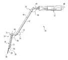
- FIG. 1is a side elevational view of a guide assembly for guiding bone engaging fasteners into a bony segment.
- FIG. 2is a top plan view of the guide assembly of FIG. 1 .
- FIG. 3is a front elevational view of the guide assembly of FIG. 1 .
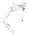
- FIG. 4is a perspective view of the guide assembly of FIG. I and a plate positioned along a spinal column segment.
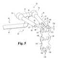
- FIG. 5is a perspective view of the guide assembly and plate of FIG. 4 looking toward the bottom of the plate.
- FIG. 6is a perspective view of another embodiment guide assembly and a plate positioned along a spinal column segment.
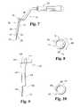
- FIG. 7is an elevational view of a distal portion of another embodiment guide assembly.
- FIG. 8is a distal end view of the distal portion of FIG. 7 .
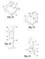
- FIG. 9is an elevational view of a distal portion of another embodiment guide assembly.
- FIG. 10is a distal end view of the distal portion of FIG. 9 .
- FIG. 11is a perspective view of a portion of a bone plate having various receptacle configurations.
- FIG. 12is a perspective view of a portion of a bone plate having various receptacle configurations.
- FIG. 13is an elevation view of another embodiment guide tube comprising a portion of a guide assembly.
- FIG. 14is an elevation view of another embodiment guide tube comprising a portion of a guide assembly.
- Guide assembly 20having application in surgical techniques for securing a bone plate to a bony segment.
- Guide assembly 20can be used in any one or combination of drilling one or more holes in the bony segment through a plate, such as a bone plate or a template, tapping one or more holes in the bony segment through the bone plate or template, and engaging bone engaging fasteners to the bony segment to secure the bone plate thereto.
- Guide assembly 20can have application in spinal plating systems, including anterior cervical plates, thoracic plates, lumbar plates and sacral plates.
- Guide assembly 20can have application with plates secured to the anterior, lateral, posterior, postero-lateral and antero-lateral aspects of the vertebrae.
- Guide assembly 20can also have application in plating systems other than spinal plating systems.
- Guide assembly 20includes a proximal handle assembly 24 and a distal guide portion 25 .
- Handle assembly 24includes a handle 22 coupled to a shaft 42 .
- Guide assembly 20includes a distal guide portion 25 extending distally from handle assembly 24 .
- Guide portion 25includes a first guide member 26 and a second guide member 66 .
- First guide member 26includes a first guide tube 27 and a first extension 28 extending distally from a distal end 36 of first guide tube 27 .
- Second guide member 66includes a second guide tube 67 and a second extension 68 extending distally from a distal end 76 of second guide tube 67 .
- First guide member 26 and second guide member 66can be connected to one another by a connecting member 41 adjacent proximal ends 34 , 74 of guide members 26 , 66 .
- First guide member 26includes a passage 30 extending through guide tube 27 and opening at proximal end 34 and distal end 36 thereof.
- Second guide member 66includes a passage 70 extending through guide tube 67 and opening at proximal end 74 and distal end 76 thereof.
- Guide tube 27can be centered about longitudinal axis 32
- guide tube 67can be centered about longitudinal axis 72 . It is further contemplated that first extension 28 extends along and is offset to one side of longitudinal axis 32 , and second extension 68 extends along and is offset to one side of longitudinal axis 72 .
- extensions 28 , 68are offset opposite handle assembly 24 relative to guide tubes 27 , 67 .
- extensions 28 , 68could be offset relative to guide tubes 27 , 67 on the same side as handle assembly 24 , or offset laterally relative to guide tubes 27 , 67 , or offset medially relative to guide tubes 27 , 67 .
- Extensions 28 , 68are contactable with the plate and/or the bony structure beneath the plate proximate the fastener hole locations in the plate to orient and align passages 30 , 70 of guide tubes 27 , 67 relative to the fastener holes while guide assembly 20 is in use.
- Passages 30 , 70can be sized to receive at least a distal portion of a drill therethrough and guide the drill bit to its proper position and orientation through a fastener hole in a plate or a plate template.
- Passages 30 , 70can also receive at least a distal portion of a tap therethrough and guide the tap to its proper position and orientation through a hole formed in the bony structure with a drill bit.
- extensions 28 , 68are positioned proximate respective fastener holes of the plate such that fastener holes remain substantially unobstructed by the respective extensions 28 , 68 . This allows bone engaging fasteners to be guided by guide tubes 27 , 67 into the plate holes while extensions 28 , 68 maintain contact with the plate.
- Longitudinal axes 32 , 72can be oriented such that the bone engaging fasteners positioned with guide tubes 27 , 67 converge distally of guide tubes 27 , 67 in the bony segment at an angle 58 .
- angle 58can be about 12 degrees; however, other convergence angles 58 ranging from about 1 degree up to 180 degrees are also contemplated.
- guide members 26 , 66can be configured so that longitudinal axes 32 , 72 diverge away from one another in the bony segment, or that longitudinal axes 32 , 72 extend parallel to one another in the bony segment.
- Handle assembly 24includes a distal offset member 40 extending between connecting member 41 and shaft 42 .
- Shaft 42can extend proximally from offset member 40 such that its central axis 44 is centered between guide members 26 , 66 .
- Offset member 40includes a central axis 54 that can form an angle 52 with central axis 44 of shaft 42 .
- Handle assembly 24further includes a proximal portion 46 extending from shaft 42 that has a central axis 48 forming angle 50 with central axis 44 of shaft 42 .
- Handle assembly 24can further include a handle 22 coupled to or formed with proximal portion 46 .
- Angles 50 and 52can be selected to provide the surgeon clear access to insert tools, fasteners and the like through the proximal end openings of passages 30 , 70 of guide tubes 27 , 67 , respectively.
- angle 52can be about 58 degrees and angle E 4 can be about 122 degrees.
- Other embodimentscontemplate other values for angle 52 ranging from 90 degrees or more to about 10 degrees, and values for angle 50 ranging from about 90 degrees or less to about 170 degrees.
- shaft 42need not be centered between guide members 26 , 66 , and also could extend laterally from one of the guide members 26 , 66 .
- shaft 42could extend substantially parallel to guide members 26 , 66 , or could extend along or in the direction of the plate positioned adjacent to the bony segment.
- handle 22could be provided along shaft 42 .
- shaft 42could extend from connecting portion 41 .
- Other variations in handle assembly 24are contemplated that are suitable for positioning guide members 26 , 46 adjacent a bone plate or template in the patient's body.
- Longitudinal axes 32 , 72 of guide members 26 , 46can be oriented relative to central axis 54 of offset portion 40 by an angle 56 .
- Angle 56can range from 10 degrees to about 90 degrees depending on the desired orientation of guide portion 25 relative to the handle assembly 24 .
- angle 56can be about 102 degrees to facilitate placement of the bone engaging fasteners at a 12 degree cephalad or caudal orientation relative to the plate.
- Other configurationsare also contemplated, including configurations where guide portion 25 is connected with shaft 42 , and orientations in which axes 32 , 72 extend perpendicular to or at an angle relative to axis 48 of handle 22 .
- FIGS. 4 and 5one specific application of guide assembly 20 with a plate along a spinal column segment will be discussed.
- a spinal column segment 100having a first vertebra 102 , a second vertebra 104 , and a third vertebra 106 .
- a first disc space 108is located between first and second vertebrae 102 and 104
- a second disc space 110is located between second and third vertebrae 104 and 106 .
- an implantsuch as implant 112
- a plate 130can be positioned along any one or all of the vertebrae 102 , 104 , 106 .
- Plate 130includes a first pair of holes 132 , 134 aligned with first vertebra 102 , a second pair of holes 136 , 138 aligned with second vertebra 104 , and a third pair of holes 146 , 148 ( FIG. 5 ) aligned with third vertebra 106 .
- Bone engaging fastenerssuch as fasteners 142 , 144 , can be positioned through any one or combination of the holes with guide assembly 20 to secure plate 130 to spinal column segment 100 or to properly position the bone engaging fasteners relative to plate 130 for engagement with a bone plate.
- plate 130could be a bone plate, as shown, or a template. Plate 130 could be configured to span one, two, or three or more vertebrae. It is also contemplated that only a single hole in the plate can be provided at any one or all of the vertebrae, or that three or more holes can be provided at any one or all of the vertebrae.
- a retaining assembly 144can be provided with plate 130 in the form of a bone plate to prevent fastener back-out from the holes. Retaining assembly 144 can be associated with each of the plate holes, or associated with any subset of the plate holes. Multiple retaining assemblies could be provided so that all or less than all of the plate holes have a retaining assembly associated therewith.
- implant 112could be a bone graft, interbody fusion device, artificial disc device, or other interbody implant.
- implantscan be made from bone material, man-made material, or combinations thereof.
- bone growth material and bone growth facilitatorscould be provided to facilitate such fusion.
- Any suitable osteogenetic material or compositionis contemplated for placement within or around implant 112 .
- Such osteogenic materialincludes, for example, autograft, allograft, xenograft, demineralized bone, synthetic and natural bone graft substitutes, such as bioceramics and polymers, and osteoinductive factors.
- a separate carrier to hold the materials in the disc space or in the implantcan also be used.
- These carrierscan include collagen-based carriers, bioceramic materials, such as BIOGLASS®, hydroxyapatite and calcium phosphate compositions.
- the carrier materialcan be provided in the form of a sponge, a block, folded sheet, putty, paste, graft material or other suitable form.
- the osteogenetic compositionscan comprise an effective amount of a bone morphogenetic protein, transforming growth factor ⁇ 1, insulin-like growth factor 1, platelet-derived growth factor, fibroblast growth factor, LIM mineralization protein (LMP), and combinations thereof or other therapeutic or infection resistant agent, held within a suitable carrier material.
- guide assembly 20can be positioned relative to plate 130 so that distal ends 38 , 78 of extensions 28 , 68 are received in receptacles in the plate.
- receptaclescould be provided by holes 132 , 134 , provided adjacent to holes 132 , 134 , and/or provided in communication with holes 132 , 134 .
- Extensions 28 , 68can contact the portion of the plate surrounding or proximate to plate holes 132 , 134 to locate guide assembly 20 relative to the plate, and to facilitate maintenance of the positioning of guide assembly 20 relative to plate 130 .
- Extensions 28 , 68can alternatively or additionally contact the bony structure underlying plate 130 proximate holes 132 , 134 to locate guide assembly 20 relative to plate 130 , and to maintain the positioning of guide assembly 20 relative to plate 130 .
- the orientation of longitudinal axes 32 , 72 of guide tubes 27 , 67 relative to plate 130can be adjusted by manipulating handle assembly 24 as indicated by arrow 160 .
- holes 132 , 134can be elongated along the longitudinal axis of plate 130 to provide a slotted arrangement. With extensions 28 , 68 in contact with the ends of holes 132 , 134 , the edge of the fasteners inserted through guide tubes 27 , 67 can be offset from the edge of the holes by distance 150 as shown in FIG. 5 . If so offset, the inserted fasteners can move in either direction in holes 132 , 134 in response to movement of the spinal column segment in compression or tension.
- Other embodimentscontemplate other shapes for holes 132 , 134 , including slotted and non-slotted holes that are circular, oval, oblong, square, rectangular or other shape suitable for receiving a bone engaging fastener.
- Guide assembly 20is shown positioned at the ends of holes 132 , 134 adjacent the end 149 of plate 130 .
- Guide assembly 20could be positioned to locate extensions 28 , 38 adjacent the opposite ends of holes 132 , 134 .
- Guide assembly 20could be used to drill holes through holes 132 , 134 into vertebra 102 , and also to tap the drilled holes. Once the holes are drilled and, if desired, tapped into vertebra 102 , bone engaging fasteners can be guided through guide tubes 27 , 67 and into the drilled and tapped holes.
- guide tubes 27 , 67could be used to guide self-tapping bone screws or fasteners into vertebra 102 , or to guide self-drilling bone screws or fasteners into vertebra 102 , without drilling and/or tapping the bony structure. The procedure can then be repeated at each vertebra 104 , 106 to secure bone engaging fasteners thereto.
- Guide members 26 , 66can have a length or other configuration selected to interact with the drilling, tapping, and/or fastener driver instrument to limit the depth of penetration into the vertebral body. For example, the instruments can contact the proximal ends of guide members 26 , 66 , or contact an internal stop surface provided in passages 30 , 70 to limit the penetration depth.
- Guide assembly 200includes a proximal handle assembly 224 and a distal guide portion 225 .
- Handle assembly 224includes a shaft 242 having a proximal portion 246 extending therefrom.
- a handle 222is coupled to or formed with proximal portion 246 .
- a distal extension 240extends from a distal end of shaft 242 and is coupled or formed with guide portion 225 .
- Guide portion 225includes a guide member 226 .
- Guide member 226includes a guide tube 227 and an extension 228 extending distally from a distal end 236 of guide tube 227 .
- Guide tube 227includes a passage 230 opening at a proximal end 234 of guide tube 227 and also opening at distal end 236 of guide tube 227 .
- Guide assembly 200includes a single guide member 226 configured to receive and guide instruments for the drilling of and, if desired, tapping of holes in respective ones of the vertebrae 102 , 104 , 106 of spinal column segment 100 through holes in plate 130 .
- Distal end 236 of guide member 227is spaced from plate 130 , and passage 230 can be sized to allow passage of a bone screw or other bone engaging fastener therethrough for guided placement and engagement of the bone engaging fastener to the respective vertebra.
- Guide assembly 200can be repositioned proximate each of or selected ones of the receptacles provided by the holes or adjacent to the holes through plate 130 to prepare each vertebra to receive and to secure a bone engaging fastener thereto.
- a distal end 238 of extension 228can contact the plate in a receptacle provided by or adjacent to a plate hole and/or contact the bony structure underlying plate 130 to position and maintain the position of guide assembly 200 proximate the plate hole during drilling, tapping, and/or fastener insertion.
- FIG. 7there is shown another embodiment guide assembly 320 having a proximal handle assembly 324 with a handle 322 and a shaft 340 .
- a guide member 326extends distally from shaft 340 .
- Guide member 326includes at least one guide tube 327 and an extension 328 extending distally from guide tube 327 .
- a passage 330extends through and opens at a proximal end 334 and a distal end 336 of guide tube 327 .
- extension 328extends from guide tube 327 along the same side of guide tube 327 from which handle assembly 324 extends.
- the extensionsare shown extending from the side of the guide tube opposite the side from which handle assembly extends. It is also contemplated that the extension could extend from a side of the guide tube laterally oriented with respect to the guide tube.
- Extension 328can be provided with a width 350 along the perimeter of guide tube 327 that is less than the perimeter of guide tube 327 . It is contemplated in one embodiment that width 350 can range from about 1 percent to about 95 percent of the perimeter of guide tube 327 . In a further embodiment, width 350 can range from about 5 percent to about 50 percent of the perimeter of guide tube 327 . In another embodiment, width 350 can range from about 5 percent to about 35 percent of the perimeter of guide tube 327 . In a further embodiment, width 350 can range from about 5 percent to about 25 percent of the perimeter of guide tube 327 .
- the other embodiment guide assemblies discussed hereincan be similarly provided with an extension having a length that occupies similar portions of the perimeter of the guide tube from which it extends.
- Extension 328can be provided with an inner surface 329 that forms an extension of a portion of the inner surface defining passage 330 .
- inner surface 329is a concave surface and opposite outer surface 331 is a convex surface extending to a distal end 338 .
- Inner surface 329can guide bone engaging fasteners, drills, taps and the like positioned through passage 330 .
- Outer surface 331can nest against a correspondingly shaped surface of the receptacle in which it is placed.
- the extensions of the other guide assembly embodiments discussed hereincan also be similarly configured to guide the placement of bone engaging fasteners, drills, taps and the like positioned through the passage of the guide tube from which the extensions extend.
- guide assembly 420having a proximal handle assembly with shaft 440 and a handle (not shown.)
- a guide member 426extends distally from shaft 440 .
- Guide member 426includes at least one guide tube 427 and an extension 428 extending distally from guide tube 427 .
- a passage 430extends through and opens at a proximal end 434 and a distal end 436 of guide tube 427 .
- extension 428is in the form of a pin that extends distally from guide tube 427 .
- extension 428can have a circular cross-section and a pointed distal end 429 for embedding in or engaging the bony structure against which it is positioned. Accordingly, the positioning of guide assembly 420 can be maintained by contact with the bony structure in addition to or in lieu of contact with the plate by extension 428 .
- extension 428 and/or the extensions of the guide assemblies discussed abovecould be integral with the guide tube from which the extension extends. It is also contemplated that the extensions could be attached to the guide tubes by any one or combination of a threaded connection, bolted connection, riveted connection, welded connection, bayonet lock, clamp, or other suitable attachment arrangement. It is contemplated that each guide tube could be provided with multiple extensions extending distally therefrom.
- plate 500includes a hole 502 extending between and opening at a proximal surface 514 and a distal surface 512 of plate 500 .
- a receptacle 504is formed in proximal surface 514 proximate hole 502 .
- Receptacle 504can extend partially into or completely through plate 500 .
- Receptacle 504is spaced from hole 502 by a plate segment 506 .
- the guide assembly extensionis positionable in receptacle 504 to orient the passage of the guide tube from which the extension extends in alignment with hole 502 .
- Plate 500includes a receptacle 510 in communication with hole 508 .
- Receptacle 510can open at proximal surface 514 and can extend partially or completely through plate 500 .
- An extension of the guide assemblyis positionable in receptacle 510 in contact with plate 500 to orient the passage of the guide tube from which the extension extends in alignment with hole 508 .
- FIG. 12shows plate 520 in which holes 522 , 524 are provided with receptacles 526 , 528 , respectively, proximate thereto.
- Receptacle 526is oriented laterally in the plate with respect to hole 522 toward the outer edge of the plate 520 .
- receptacle 528is oriented away from the end 530 of plate 520 .
- Other orientations of the receptacles relative to the plate holesare also contemplated.
- FIG. 13there is a guide member 550 for a guide assembly.
- Guide member 550includes a guide tube 552 having a passage 554 extending therethrough and opening at a distal end 556 of guide tube 552 .
- Extension 558extends distally from distal end 556 .
- the walls of guide tube 552have a first thickness 560
- extension 558has a second thickness 562 .
- second thickness 562can be less than thickness 560 .
- the reduced thickness of extension 558facilitates its positioning in, for example, receptacle 504 of plate 500 while passage 554 is aligned with hole 502 .
- Extension 558could also be positioned in, for example, receptacle 510 of plate 500 while passage 554 is aligned with hole 508 of plate 500 . Extension 558 could also be positioned in receptacles provided by the holes of the plate, such as shown with plate 130 .
- Extension 558is offset from a projection of passage 554 of guide tube 552 along extension 558 .
- the offsetcan minimize interference of the extension with the bone engaging fastener as the bone engaging fastener positioned in the plate hole.
- Other embodimentscontemplate extensions having a thickness that is the same or about the same as thickness of the wall of the guide tube.
- guide member 570for a guide assembly.
- Guide member 570includes a guide tube 572 having a passage 574 extending therethrough and opening at a distal end 576 of guide tube 572 .
- Extension 578extends distally from distal end 576 .
- Extension 578can be provided with an offset portion 580 at any location therealong such that distal end 582 is positioned away from passage 574 by distance 584 .
- Extension 578is thus offset from a projection of the passage of the guide tube along the extension.
- Extension 578could be positioned in, for example, receptacle 504 of plate 500 while passage 574 is aligned with hole 502 of plate 500 .
- Extension 578could also be positioned in, for example, receptacle 510 of plate 500 with passage 574 aligned with hole 508 of plate 500 . Extension 578 could also be positioned in receptacles provided by the holes of the plate, such as shown with plate 130 .
Landscapes
- Health & Medical Sciences (AREA)
- Surgery (AREA)
- Orthopedic Medicine & Surgery (AREA)
- Life Sciences & Earth Sciences (AREA)
- Biomedical Technology (AREA)
- Molecular Biology (AREA)
- Oral & Maxillofacial Surgery (AREA)
- Engineering & Computer Science (AREA)
- Dentistry (AREA)
- Heart & Thoracic Surgery (AREA)
- Medical Informatics (AREA)
- Nuclear Medicine, Radiotherapy & Molecular Imaging (AREA)
- Animal Behavior & Ethology (AREA)
- General Health & Medical Sciences (AREA)
- Public Health (AREA)
- Veterinary Medicine (AREA)
- Surgical Instruments (AREA)
- Prostheses (AREA)
Abstract
Description
Claims (45)
Priority Applications (1)
| Application Number | Priority Date | Filing Date | Title |
|---|---|---|---|
| US10/261,120US7625378B2 (en) | 2002-09-30 | 2002-09-30 | Devices and methods for securing a bone plate to a bony segment |
Applications Claiming Priority (1)
| Application Number | Priority Date | Filing Date | Title |
|---|---|---|---|
| US10/261,120US7625378B2 (en) | 2002-09-30 | 2002-09-30 | Devices and methods for securing a bone plate to a bony segment |
Publications (2)
| Publication Number | Publication Date |
|---|---|
| US20040092947A1 US20040092947A1 (en) | 2004-05-13 |
| US7625378B2true US7625378B2 (en) | 2009-12-01 |
Family
ID=32228720
Family Applications (1)
| Application Number | Title | Priority Date | Filing Date |
|---|---|---|---|
| US10/261,120Expired - Fee RelatedUS7625378B2 (en) | 2002-09-30 | 2002-09-30 | Devices and methods for securing a bone plate to a bony segment |
Country Status (1)
| Country | Link |
|---|---|
| US (1) | US7625378B2 (en) |
Cited By (57)
| Publication number | Priority date | Publication date | Assignee | Title |
|---|---|---|---|---|
| US20080097436A1 (en)* | 2006-04-21 | 2008-04-24 | Culbert Brad S | Method and apparatus for spinal fixation |
| US20090118768A1 (en)* | 2007-11-02 | 2009-05-07 | Sixto Jr Robert | Elbow Fracture Fixation System |
| US20090177208A1 (en)* | 2007-07-11 | 2009-07-09 | Strnad Lee A | Surgical drill guide having keyway for axial alignment of a fastener for use for an orthopedic plate |
| US20100241174A1 (en)* | 2007-10-16 | 2010-09-23 | Robinson James C | Bone screw retaining and removal system |
| US8109977B2 (en) | 2002-07-19 | 2012-02-07 | Interventional Spine, Inc. | Method and apparatus for spinal fixation |
| US8202304B2 (en) | 2002-08-21 | 2012-06-19 | Theken Spine, Llc | Methods and systems for performing spinal surgery |
| US20130017568A1 (en)* | 2011-07-13 | 2013-01-17 | Teena Enriquez | Inoculation Loop Devices Having an Angled End and Methods of Making and Using the Same |
| US8574270B2 (en) | 2009-03-13 | 2013-11-05 | Spinal Simplicity Llc | Bone plate assembly with bone screw retention features |
| US8652180B2 (en) | 2010-09-27 | 2014-02-18 | Acumed Llc | Handle assembly having a radiopaque region to facilitate positioning a bone plate on bone |
| US8814915B2 (en) | 2009-03-13 | 2014-08-26 | Spinal Simplicity Llc | Dynamic vertebral column plate system |
| US20140276881A1 (en)* | 2013-03-12 | 2014-09-18 | Charles Taylor | Surgical Staple Guide and Delivery Device |
| US20140303635A1 (en)* | 2011-10-03 | 2014-10-09 | Smith & Nephew, Inc. | Ovoid tunnel guide and method of acl reconstruction |
| US8974504B2 (en) | 2012-05-10 | 2015-03-10 | Spinal Simplicity Llc | Dynamic bone fracture plates |
| US8986354B2 (en) | 2012-02-14 | 2015-03-24 | Zavation Llc | Surgical kit for spinal surgery |
| US9050151B2 (en) | 2012-03-06 | 2015-06-09 | Stryker Trauma Sa | Bone plate and aiming block |
| USD747479S1 (en)* | 2014-08-05 | 2016-01-12 | Biomedical Enterprises, Inc. | Orthopedic drill guide |
| USD747803S1 (en)* | 2014-07-23 | 2016-01-19 | Biomedical Enterprises, Inc. | Orthopedic drill guide |
| USD768853S1 (en)* | 2013-10-23 | 2016-10-11 | Eca Medical Instruments | Medical instrument with waffle handle with bent shaft |
| US9522028B2 (en) | 2013-07-03 | 2016-12-20 | Interventional Spine, Inc. | Method and apparatus for sacroiliac joint fixation |
| US9522070B2 (en) | 2013-03-07 | 2016-12-20 | Interventional Spine, Inc. | Intervertebral implant |
| US9821378B2 (en) | 2015-08-11 | 2017-11-21 | Biomedical Enterprises, Inc. | Drill guide and method of manufacture thereof |
| US9826992B2 (en) | 2007-12-21 | 2017-11-28 | Smith & Nephew, Inc. | Multiple portal guide |
| US9839530B2 (en) | 2007-06-26 | 2017-12-12 | DePuy Synthes Products, Inc. | Highly lordosed fusion cage |
| US9883951B2 (en) | 2012-08-30 | 2018-02-06 | Interventional Spine, Inc. | Artificial disc |
| US9888936B2 (en) | 2010-09-27 | 2018-02-13 | Smith & Nephew, Inc. | Device and methods for use during arthroscopic surgery |
| US9895236B2 (en) | 2010-06-24 | 2018-02-20 | DePuy Synthes Products, Inc. | Enhanced cage insertion assembly |
| US9913727B2 (en) | 2015-07-02 | 2018-03-13 | Medos International Sarl | Expandable implant |
| US9913636B2 (en) | 2007-12-21 | 2018-03-13 | Smith & Nephew, Inc. | Multiple portal guide |
| US9931223B2 (en) | 2008-04-05 | 2018-04-03 | DePuy Synthes Products, Inc. | Expandable intervertebral implant |
| US9993349B2 (en) | 2002-06-27 | 2018-06-12 | DePuy Synthes Products, Inc. | Intervertebral disc |
| US10058433B2 (en) | 2012-07-26 | 2018-08-28 | DePuy Synthes Products, Inc. | Expandable implant |
| US10219812B2 (en) | 2010-11-03 | 2019-03-05 | Smith & Nephew, Inc. | Drill guide |
| US10390963B2 (en) | 2006-12-07 | 2019-08-27 | DePuy Synthes Products, Inc. | Intervertebral implant |
| US10398563B2 (en) | 2017-05-08 | 2019-09-03 | Medos International Sarl | Expandable cage |
| US10433977B2 (en) | 2008-01-17 | 2019-10-08 | DePuy Synthes Products, Inc. | Expandable intervertebral implant and associated method of manufacturing the same |
| US10500062B2 (en) | 2009-12-10 | 2019-12-10 | DePuy Synthes Products, Inc. | Bellows-like expandable interbody fusion cage |
| US10537436B2 (en) | 2016-11-01 | 2020-01-21 | DePuy Synthes Products, Inc. | Curved expandable cage |
| US10548741B2 (en) | 2010-06-29 | 2020-02-04 | DePuy Synthes Products, Inc. | Distractible intervertebral implant |
| US10631884B2 (en) | 2017-06-05 | 2020-04-28 | Conmed Corporation | Multi-barrel drill guide |
| US10888433B2 (en) | 2016-12-14 | 2021-01-12 | DePuy Synthes Products, Inc. | Intervertebral implant inserter and related methods |
| US10940016B2 (en) | 2017-07-05 | 2021-03-09 | Medos International Sarl | Expandable intervertebral fusion cage |
| US11123117B1 (en) | 2011-11-01 | 2021-09-21 | Nuvasive, Inc. | Surgical fixation system and related methods |
| US11344424B2 (en) | 2017-06-14 | 2022-05-31 | Medos International Sarl | Expandable intervertebral implant and related methods |
| US11426290B2 (en) | 2015-03-06 | 2022-08-30 | DePuy Synthes Products, Inc. | Expandable intervertebral implant, system, kit and method |
| US11426286B2 (en) | 2020-03-06 | 2022-08-30 | Eit Emerging Implant Technologies Gmbh | Expandable intervertebral implant |
| US11446156B2 (en) | 2018-10-25 | 2022-09-20 | Medos International Sarl | Expandable intervertebral implant, inserter instrument, and related methods |
| US11452607B2 (en) | 2010-10-11 | 2022-09-27 | DePuy Synthes Products, Inc. | Expandable interspinous process spacer implant |
| US11471173B2 (en) | 2017-06-05 | 2022-10-18 | Conmed Corporation | Multi-barrel drill guide and anchor deployment assembly |
| US11510788B2 (en) | 2016-06-28 | 2022-11-29 | Eit Emerging Implant Technologies Gmbh | Expandable, angularly adjustable intervertebral cages |
| US11596522B2 (en) | 2016-06-28 | 2023-03-07 | Eit Emerging Implant Technologies Gmbh | Expandable and angularly adjustable intervertebral cages with articulating joint |
| US11612491B2 (en) | 2009-03-30 | 2023-03-28 | DePuy Synthes Products, Inc. | Zero profile spinal fusion cage |
| US11752009B2 (en) | 2021-04-06 | 2023-09-12 | Medos International Sarl | Expandable intervertebral fusion cage |
| US11850160B2 (en) | 2021-03-26 | 2023-12-26 | Medos International Sarl | Expandable lordotic intervertebral fusion cage |
| US11911287B2 (en) | 2010-06-24 | 2024-02-27 | DePuy Synthes Products, Inc. | Lateral spondylolisthesis reduction cage |
| USRE49973E1 (en) | 2013-02-28 | 2024-05-21 | DePuy Synthes Products, Inc. | Expandable intervertebral implant, system, kit and method |
| US12090064B2 (en) | 2022-03-01 | 2024-09-17 | Medos International Sarl | Stabilization members for expandable intervertebral implants, and related systems and methods |
| US12440346B2 (en) | 2023-03-31 | 2025-10-14 | DePuy Synthes Products, Inc. | Expandable intervertebral implant |
Families Citing this family (42)
| Publication number | Priority date | Publication date | Assignee | Title |
|---|---|---|---|---|
| US20030187443A1 (en)* | 2002-03-27 | 2003-10-02 | Carl Lauryssen | Anterior bone plate system and method of use |
| US7175624B2 (en)* | 2002-12-31 | 2007-02-13 | Depuy Spine, Inc. | Bone plate and screw system allowing bi-directional assembly |
| US7914561B2 (en) | 2002-12-31 | 2011-03-29 | Depuy Spine, Inc. | Resilient bone plate and screw system allowing bi-directional assembly |
| US7048739B2 (en)* | 2002-12-31 | 2006-05-23 | Depuy Spine, Inc. | Bone plate and resilient screw system allowing bi-directional assembly |
| US7341591B2 (en)* | 2003-01-30 | 2008-03-11 | Depuy Spine, Inc. | Anterior buttress staple |
| US6960216B2 (en)* | 2003-03-21 | 2005-11-01 | Depuy Acromed, Inc. | Modular drill guide |
| US7909829B2 (en)* | 2003-06-27 | 2011-03-22 | Depuy Spine, Inc. | Tissue retractor and drill guide |
| US7776047B2 (en)* | 2003-04-09 | 2010-08-17 | Depuy Spine, Inc. | Guide for spinal tools, implants, and devices |
| US20040210232A1 (en)* | 2003-04-09 | 2004-10-21 | Tushar Patel | Guide device and plate inserter |
| US7416553B2 (en)* | 2003-04-09 | 2008-08-26 | Depuy Acromed, Inc. | Drill guide and plate inserter |
| US7935123B2 (en)* | 2003-04-09 | 2011-05-03 | Depuy Acromed, Inc. | Drill guide with alignment feature |
| US7909848B2 (en)* | 2003-06-27 | 2011-03-22 | Depuy Spine, Inc. | Tissue retractor and guide device |
| US7488327B2 (en)* | 2004-04-12 | 2009-02-10 | Synthes (U.S.A.) | Free hand drill guide |
| US7572282B2 (en)* | 2004-04-23 | 2009-08-11 | Depuy Spine Sarl | Spinal fixation plates and plate extensions |
| US20050240181A1 (en)* | 2004-04-23 | 2005-10-27 | Boomer Mark C | Spinal implant connectors |
| US20060106387A1 (en)* | 2004-11-16 | 2006-05-18 | Depuy Spine, Inc. | Spinal plate system and method of use |
| US7621916B2 (en)* | 2004-11-18 | 2009-11-24 | Depuy Spine, Inc. | Cervical bone preparation tool and implant guide systems |
| US7166111B2 (en)* | 2004-12-08 | 2007-01-23 | Depuy Spine, Inc. | Spinal plate and drill guide |
| US20060155284A1 (en)* | 2005-01-07 | 2006-07-13 | Depuy Spine Sarl | Occipital plate and guide systems |
| US8177823B2 (en) | 2005-06-30 | 2012-05-15 | Depuy Spine Sarl | Orthopedic clamping hook assembly |
| US9119677B2 (en) | 2005-12-09 | 2015-09-01 | DePuy Synthes Products, Inc. | Spinal plate and drill guide |
| US7473255B2 (en)* | 2006-02-08 | 2009-01-06 | Synthes (U.S.A.) | Transbuccal plate holding cannula |
| US20080300605A1 (en)* | 2007-06-01 | 2008-12-04 | Rinner James A | Pedicle protractor tool |
| US9283010B2 (en)* | 2008-05-05 | 2016-03-15 | Trimed, Incorporated | Contoured bone plate for fracture fixation having hook members and holder/impactor for same |
| US8177822B2 (en)* | 2008-05-05 | 2012-05-15 | Lars G. Tellman | Contoured bone plate for fracture fixation having hook members and drill guide for same |
| US20090312782A1 (en)* | 2008-06-13 | 2009-12-17 | Maxwell Choongwon Park | Method and apparatus for repairing tendons |
| US8425573B2 (en)* | 2008-10-24 | 2013-04-23 | The Cleveland Clinic Foundation | Method and system for attaching a plate to a bone |
| US9138246B2 (en)* | 2010-02-19 | 2015-09-22 | Arthrex, Inc. | Elbow reconstruction instruments and techniques |
| US8668723B2 (en) | 2011-07-19 | 2014-03-11 | Neurostructures, Inc. | Anterior cervical plate |
| US20150079146A1 (en)* | 2012-04-12 | 2015-03-19 | Novabone Products, Llc. | Bioactive glass fiber mesh for repair of hard tissues |
| EP3158952B1 (en)* | 2012-09-14 | 2019-10-23 | Synthes GmbH | Multihole drill sleeve with protection sleeve |
| US9750512B2 (en) | 2013-10-21 | 2017-09-05 | Zimmer Spine, Inc. | Drill guide for installing a bone plate |
| ES2620441T3 (en) | 2013-11-08 | 2017-06-28 | Robert J. Medoff | DRILLING GUIDES AND INSERTERS FOR BONE PLATES THAT HAVE HOOK ELEMENTS |
| US9629664B2 (en) | 2014-01-20 | 2017-04-25 | Neurostructures, Inc. | Anterior cervical plate |
| US9486250B2 (en) | 2014-02-20 | 2016-11-08 | Mastros Innovations, LLC. | Lateral plate |
| US10512547B2 (en) | 2017-05-04 | 2019-12-24 | Neurostructures, Inc. | Interbody spacer |
| US10980641B2 (en) | 2017-05-04 | 2021-04-20 | Neurostructures, Inc. | Interbody spacer |
| US11076892B2 (en) | 2018-08-03 | 2021-08-03 | Neurostructures, Inc. | Anterior cervical plate |
| US11071629B2 (en) | 2018-10-13 | 2021-07-27 | Neurostructures Inc. | Interbody spacer |
| US11382761B2 (en) | 2020-04-11 | 2022-07-12 | Neurostructures, Inc. | Expandable interbody spacer |
| US11304817B2 (en) | 2020-06-05 | 2022-04-19 | Neurostructures, Inc. | Expandable interbody spacer |
| US11717419B2 (en) | 2020-12-10 | 2023-08-08 | Neurostructures, Inc. | Expandable interbody spacer |
Citations (36)
| Publication number | Priority date | Publication date | Assignee | Title |
|---|---|---|---|---|
| US3439671A (en)* | 1965-04-01 | 1969-04-22 | Orthopedic Equipment Co | Instrument for spiking fractured bones |
| US3867932A (en)* | 1974-01-18 | 1975-02-25 | Donald R Huene | Assembly for inserting rigid shafts into fractured bones |
| US4232660A (en)* | 1979-03-26 | 1980-11-11 | Coles Robert L | Winged irrigating surgical retractor |
| US4461305A (en)* | 1981-09-04 | 1984-07-24 | Cibley Leonard J | Automated biopsy device |
| US4945904A (en)* | 1989-10-25 | 1990-08-07 | W. L. Gore & Associates, Inc. | Orthopedic drill guide device |
| US5084049A (en)* | 1989-02-08 | 1992-01-28 | Acromed Corporation | Transverse connector for spinal column corrective devices |
| US5147367A (en)* | 1991-02-22 | 1992-09-15 | Ellis Alfred B | Drill pin guide and method for orthopedic surgery |
| US5298254A (en)* | 1989-09-21 | 1994-03-29 | Osteotech, Inc. | Shaped, swollen demineralized bone and its use in bone repair |
| US5423826A (en)* | 1993-02-05 | 1995-06-13 | Danek Medical, Inc. | Anterior cervical plate holder/drill guide and method of use |
| US5669915A (en)* | 1995-03-22 | 1997-09-23 | Aesculap Ag | Drilling jig for surgical drilling tools |
| US5676666A (en)* | 1994-08-23 | 1997-10-14 | Spinetech, Inc. | Cervical spine stabilization system |
| US5755721A (en) | 1996-03-13 | 1998-05-26 | Synthes | Plate holding drill guide and trocar and method of holding a plate |
| USD401335S (en)* | 1997-07-28 | 1998-11-17 | Tibor Koros | Combined cervical and lumbar extractor and injector surgical instrument |
| US5851207A (en) | 1997-07-01 | 1998-12-22 | Synthes (U.S.A.) | Freely separable surgical drill guide and plate |
| US5885300A (en)* | 1996-04-01 | 1999-03-23 | Asahi Kogaku Kogyo Kabushiki Kaisha | Guide apparatus of intervertebral implant |
| US6066142A (en) | 1998-10-22 | 2000-05-23 | Depuy Orthopaedics, Inc. | Variable position bone drilling alignment guide |
| US6193721B1 (en) | 1997-02-11 | 2001-02-27 | Gary K. Michelson | Multi-lock anterior cervical plating system |
| US6193723B1 (en)* | 1994-12-16 | 2001-02-27 | Exactech, Inc. | Intramedullary alignment guide tool |
| US6235034B1 (en) | 1997-10-24 | 2001-05-22 | Robert S. Bray | Bone plate and bone screw guide mechanism |
| US6258089B1 (en)* | 1998-05-19 | 2001-07-10 | Alphatec Manufacturing, Inc. | Anterior cervical plate and fixation system |
| US20010047172A1 (en) | 1999-10-13 | 2001-11-29 | Foley Kevin T. | System and method for securing a plate to the spinal column |
| US6332887B1 (en) | 1999-04-06 | 2001-12-25 | Benjamin D. Knox | Spinal fusion instrumentation system |
| US6342056B1 (en) | 2000-02-04 | 2002-01-29 | Jean-Marc Mac-Thiong | Surgical drill guide and method for using the same |
| US6342057B1 (en) | 2000-04-28 | 2002-01-29 | Synthes (Usa) | Remotely aligned surgical drill guide |
| US6379364B1 (en) | 2000-04-28 | 2002-04-30 | Synthes (Usa) | Dual drill guide for a locking bone plate |
| US6436103B1 (en) | 2000-12-21 | 2002-08-20 | Loubert Suddaby | Drill guide and plate attachment mechanism for orthopedic plating |
| WO2002080791A1 (en) | 2001-04-06 | 2002-10-17 | Sdgi Holdings, Inc | Anterior plating system and method |
| US6506151B2 (en)* | 1998-04-09 | 2003-01-14 | Sdgi Holdings, Inc. | Method and instrumentation for posterior interbody fusion |
| US20030233098A1 (en)* | 2002-06-18 | 2003-12-18 | Stryker Spine | Variable depth drill guide |
| US20040015174A1 (en)* | 2002-07-22 | 2004-01-22 | Null William B. | Guide assembly for engaging a bone plate to a bony segment |
| US6682535B2 (en)* | 1999-06-16 | 2004-01-27 | Thomas Hoogland | Apparatus for decompressing herniated intervertebral discs |
| US6793658B2 (en)* | 2001-04-06 | 2004-09-21 | Society De Fabrication De Material Orthopedique, S.A. | Anterior plating system and method |
| US20050143741A1 (en)* | 2001-09-26 | 2005-06-30 | Andre Timmermans | Device for introducing a suture thread anchor into a bone |
| US6916323B2 (en)* | 2001-08-21 | 2005-07-12 | Depuy Products, Inc. | Method and apparatus for percutaneously securing a bone screw and a bone plate to a bone of a patient |
| US6929606B2 (en)* | 2001-01-29 | 2005-08-16 | Depuy Spine, Inc. | Retractor and method for spinal pedicle screw placement |
| US20060142762A1 (en)* | 1993-06-10 | 2006-06-29 | Michelson Gary K | Apparatus and method for sequential distraction |
- 2002
- 2002-09-30USUS10/261,120patent/US7625378B2/ennot_activeExpired - Fee Related
Patent Citations (37)
| Publication number | Priority date | Publication date | Assignee | Title |
|---|---|---|---|---|
| US3439671A (en)* | 1965-04-01 | 1969-04-22 | Orthopedic Equipment Co | Instrument for spiking fractured bones |
| US3867932A (en)* | 1974-01-18 | 1975-02-25 | Donald R Huene | Assembly for inserting rigid shafts into fractured bones |
| US4232660A (en)* | 1979-03-26 | 1980-11-11 | Coles Robert L | Winged irrigating surgical retractor |
| US4461305A (en)* | 1981-09-04 | 1984-07-24 | Cibley Leonard J | Automated biopsy device |
| US5084049A (en)* | 1989-02-08 | 1992-01-28 | Acromed Corporation | Transverse connector for spinal column corrective devices |
| US5298254A (en)* | 1989-09-21 | 1994-03-29 | Osteotech, Inc. | Shaped, swollen demineralized bone and its use in bone repair |
| US4945904A (en)* | 1989-10-25 | 1990-08-07 | W. L. Gore & Associates, Inc. | Orthopedic drill guide device |
| US5147367A (en)* | 1991-02-22 | 1992-09-15 | Ellis Alfred B | Drill pin guide and method for orthopedic surgery |
| US5423826A (en)* | 1993-02-05 | 1995-06-13 | Danek Medical, Inc. | Anterior cervical plate holder/drill guide and method of use |
| US20060142762A1 (en)* | 1993-06-10 | 2006-06-29 | Michelson Gary K | Apparatus and method for sequential distraction |
| US5676666A (en)* | 1994-08-23 | 1997-10-14 | Spinetech, Inc. | Cervical spine stabilization system |
| US6193723B1 (en)* | 1994-12-16 | 2001-02-27 | Exactech, Inc. | Intramedullary alignment guide tool |
| US5669915A (en)* | 1995-03-22 | 1997-09-23 | Aesculap Ag | Drilling jig for surgical drilling tools |
| US5755721A (en) | 1996-03-13 | 1998-05-26 | Synthes | Plate holding drill guide and trocar and method of holding a plate |
| US5885300A (en)* | 1996-04-01 | 1999-03-23 | Asahi Kogaku Kogyo Kabushiki Kaisha | Guide apparatus of intervertebral implant |
| US6193721B1 (en) | 1997-02-11 | 2001-02-27 | Gary K. Michelson | Multi-lock anterior cervical plating system |
| US5851207A (en) | 1997-07-01 | 1998-12-22 | Synthes (U.S.A.) | Freely separable surgical drill guide and plate |
| USD401335S (en)* | 1997-07-28 | 1998-11-17 | Tibor Koros | Combined cervical and lumbar extractor and injector surgical instrument |
| US6235034B1 (en) | 1997-10-24 | 2001-05-22 | Robert S. Bray | Bone plate and bone screw guide mechanism |
| US6506151B2 (en)* | 1998-04-09 | 2003-01-14 | Sdgi Holdings, Inc. | Method and instrumentation for posterior interbody fusion |
| US6258089B1 (en)* | 1998-05-19 | 2001-07-10 | Alphatec Manufacturing, Inc. | Anterior cervical plate and fixation system |
| US6066142A (en) | 1998-10-22 | 2000-05-23 | Depuy Orthopaedics, Inc. | Variable position bone drilling alignment guide |
| US6332887B1 (en) | 1999-04-06 | 2001-12-25 | Benjamin D. Knox | Spinal fusion instrumentation system |
| US6682535B2 (en)* | 1999-06-16 | 2004-01-27 | Thomas Hoogland | Apparatus for decompressing herniated intervertebral discs |
| US6692503B2 (en)* | 1999-10-13 | 2004-02-17 | Sdgi Holdings, Inc | System and method for securing a plate to the spinal column |
| US20010047172A1 (en) | 1999-10-13 | 2001-11-29 | Foley Kevin T. | System and method for securing a plate to the spinal column |
| US6342056B1 (en) | 2000-02-04 | 2002-01-29 | Jean-Marc Mac-Thiong | Surgical drill guide and method for using the same |
| US6379364B1 (en) | 2000-04-28 | 2002-04-30 | Synthes (Usa) | Dual drill guide for a locking bone plate |
| US6342057B1 (en) | 2000-04-28 | 2002-01-29 | Synthes (Usa) | Remotely aligned surgical drill guide |
| US6436103B1 (en) | 2000-12-21 | 2002-08-20 | Loubert Suddaby | Drill guide and plate attachment mechanism for orthopedic plating |
| US6929606B2 (en)* | 2001-01-29 | 2005-08-16 | Depuy Spine, Inc. | Retractor and method for spinal pedicle screw placement |
| WO2002080791A1 (en) | 2001-04-06 | 2002-10-17 | Sdgi Holdings, Inc | Anterior plating system and method |
| US6793658B2 (en)* | 2001-04-06 | 2004-09-21 | Society De Fabrication De Material Orthopedique, S.A. | Anterior plating system and method |
| US6916323B2 (en)* | 2001-08-21 | 2005-07-12 | Depuy Products, Inc. | Method and apparatus for percutaneously securing a bone screw and a bone plate to a bone of a patient |
| US20050143741A1 (en)* | 2001-09-26 | 2005-06-30 | Andre Timmermans | Device for introducing a suture thread anchor into a bone |
| US20030233098A1 (en)* | 2002-06-18 | 2003-12-18 | Stryker Spine | Variable depth drill guide |
| US20040015174A1 (en)* | 2002-07-22 | 2004-01-22 | Null William B. | Guide assembly for engaging a bone plate to a bony segment |
Non-Patent Citations (3)
| Title |
|---|
| Gary L. Lowery, MD, PhD; Sugical Technique; Orion Anterior Cervical Plate System; Sofamor Danek The Spine Specialist; pp. 1-24. |
| Thomas A. Zdeblick, M.D. and Harry N. Herkowitz, M.D.; Premier Anterior Cervical Plate System, Surgical Technique; Premier Anterior Cervical Plate System; 2000 Medtronic Sofamor Danek. |
| Zephir Anterior Cervical Plate System, Surgical Technique; 2000 Medtronic Sofamor Danek; pp. 1-8. |
Cited By (110)
| Publication number | Priority date | Publication date | Assignee | Title |
|---|---|---|---|---|
| US9993349B2 (en) | 2002-06-27 | 2018-06-12 | DePuy Synthes Products, Inc. | Intervertebral disc |
| US8945190B2 (en) | 2002-07-19 | 2015-02-03 | Interventional Spine, Inc. | Method and apparatus for spinal fixation |
| US9713486B2 (en) | 2002-07-19 | 2017-07-25 | DePuy Synthes Products, Inc. | Method and apparatus for spinal fixation |
| US8109977B2 (en) | 2002-07-19 | 2012-02-07 | Interventional Spine, Inc. | Method and apparatus for spinal fixation |
| US8579942B2 (en) | 2002-08-21 | 2013-11-12 | Theken Spine, Llc | Systems, methods and tools for spinal surgery |
| US8202304B2 (en) | 2002-08-21 | 2012-06-19 | Theken Spine, Llc | Methods and systems for performing spinal surgery |
| US8382802B2 (en) | 2002-08-21 | 2013-02-26 | Theken Spine, Llc | Systems, methods and devices for placement of bone anchors and connectors |
| US7938832B2 (en)* | 2006-04-21 | 2011-05-10 | Interventional Spine, Inc. | Method and apparatus for spinal fixation |
| US20110218575A1 (en)* | 2006-04-21 | 2011-09-08 | Interventional Spine, Inc. | Method and apparatus for spinal fixation |
| US9101411B2 (en) | 2006-04-21 | 2015-08-11 | Interventional Spine, Inc. | Method and apparatus for spinal fixation |
| US20080097436A1 (en)* | 2006-04-21 | 2008-04-24 | Culbert Brad S | Method and apparatus for spinal fixation |
| US10390963B2 (en) | 2006-12-07 | 2019-08-27 | DePuy Synthes Products, Inc. | Intervertebral implant |
| US10583015B2 (en) | 2006-12-07 | 2020-03-10 | DePuy Synthes Products, Inc. | Intervertebral implant |
| US11712345B2 (en) | 2006-12-07 | 2023-08-01 | DePuy Synthes Products, Inc. | Intervertebral implant |
| US11497618B2 (en) | 2006-12-07 | 2022-11-15 | DePuy Synthes Products, Inc. | Intervertebral implant |
| US11273050B2 (en) | 2006-12-07 | 2022-03-15 | DePuy Synthes Products, Inc. | Intervertebral implant |
| US11642229B2 (en) | 2006-12-07 | 2023-05-09 | DePuy Synthes Products, Inc. | Intervertebral implant |
| US10398566B2 (en) | 2006-12-07 | 2019-09-03 | DePuy Synthes Products, Inc. | Intervertebral implant |
| US11432942B2 (en) | 2006-12-07 | 2022-09-06 | DePuy Synthes Products, Inc. | Intervertebral implant |
| US11660206B2 (en) | 2006-12-07 | 2023-05-30 | DePuy Synthes Products, Inc. | Intervertebral implant |
| US10973652B2 (en) | 2007-06-26 | 2021-04-13 | DePuy Synthes Products, Inc. | Highly lordosed fusion cage |
| US11622868B2 (en) | 2007-06-26 | 2023-04-11 | DePuy Synthes Products, Inc. | Highly lordosed fusion cage |
| US9839530B2 (en) | 2007-06-26 | 2017-12-12 | DePuy Synthes Products, Inc. | Highly lordosed fusion cage |
| US20090177208A1 (en)* | 2007-07-11 | 2009-07-09 | Strnad Lee A | Surgical drill guide having keyway for axial alignment of a fastener for use for an orthopedic plate |
| US9668759B2 (en) | 2007-07-11 | 2017-06-06 | Orthohelix Surgical Designs, Inc. | Surgical drill guide having keyway for axial alignment of a fastener for use for an orthopedic plate |
| US8496693B2 (en) | 2007-10-16 | 2013-07-30 | Amendia Inc. | Bone screw retaining and removal system |
| US20100241174A1 (en)* | 2007-10-16 | 2010-09-23 | Robinson James C | Bone screw retaining and removal system |
| US8568462B2 (en)* | 2007-11-02 | 2013-10-29 | Biomet C.V. | Bone plate system with two different types of drill guides |
| US9750549B2 (en) | 2007-11-02 | 2017-09-05 | Biomet C.V. | Plate benders for bone plates |
| US20090118768A1 (en)* | 2007-11-02 | 2009-05-07 | Sixto Jr Robert | Elbow Fracture Fixation System |
| US9913636B2 (en) | 2007-12-21 | 2018-03-13 | Smith & Nephew, Inc. | Multiple portal guide |
| US9826992B2 (en) | 2007-12-21 | 2017-11-28 | Smith & Nephew, Inc. | Multiple portal guide |
| US10433977B2 (en) | 2008-01-17 | 2019-10-08 | DePuy Synthes Products, Inc. | Expandable intervertebral implant and associated method of manufacturing the same |
| US10449058B2 (en) | 2008-01-17 | 2019-10-22 | DePuy Synthes Products, Inc. | Expandable intervertebral implant and associated method of manufacturing the same |
| US11737881B2 (en) | 2008-01-17 | 2023-08-29 | DePuy Synthes Products, Inc. | Expandable intervertebral implant and associated method of manufacturing the same |
| US9993350B2 (en) | 2008-04-05 | 2018-06-12 | DePuy Synthes Products, Inc. | Expandable intervertebral implant |
| US11712342B2 (en) | 2008-04-05 | 2023-08-01 | DePuy Synthes Products, Inc. | Expandable intervertebral implant |
| US12023255B2 (en) | 2008-04-05 | 2024-07-02 | DePuy Synthes Products, Inc. | Expandable inter vertebral implant |
| US11617655B2 (en) | 2008-04-05 | 2023-04-04 | DePuy Synthes Products, Inc. | Expandable intervertebral implant |
| US11707359B2 (en) | 2008-04-05 | 2023-07-25 | DePuy Synthes Products, Inc. | Expandable intervertebral implant |
| US9931223B2 (en) | 2008-04-05 | 2018-04-03 | DePuy Synthes Products, Inc. | Expandable intervertebral implant |
| US11712341B2 (en) | 2008-04-05 | 2023-08-01 | DePuy Synthes Products, Inc. | Expandable intervertebral implant |
| US10449056B2 (en) | 2008-04-05 | 2019-10-22 | DePuy Synthes Products, Inc. | Expandable intervertebral implant |
| US12011361B2 (en) | 2008-04-05 | 2024-06-18 | DePuy Synthes Products, Inc. | Expandable intervertebral implant |
| US11701234B2 (en) | 2008-04-05 | 2023-07-18 | DePuy Synthes Products, Inc. | Expandable intervertebral implant |
| US11602438B2 (en) | 2008-04-05 | 2023-03-14 | DePuy Synthes Products, Inc. | Expandable intervertebral implant |
| US8882812B2 (en) | 2009-03-13 | 2014-11-11 | Spinal Simplicity Llc | Bone plate assembly with plates that ratchet together |
| US8814915B2 (en) | 2009-03-13 | 2014-08-26 | Spinal Simplicity Llc | Dynamic vertebral column plate system |
| US8574270B2 (en) | 2009-03-13 | 2013-11-05 | Spinal Simplicity Llc | Bone plate assembly with bone screw retention features |
| US11612491B2 (en) | 2009-03-30 | 2023-03-28 | DePuy Synthes Products, Inc. | Zero profile spinal fusion cage |
| US12097124B2 (en) | 2009-03-30 | 2024-09-24 | DePuy Synthes Products, Inc. | Zero profile spinal fusion cage |
| US11607321B2 (en) | 2009-12-10 | 2023-03-21 | DePuy Synthes Products, Inc. | Bellows-like expandable interbody fusion cage |
| US10500062B2 (en) | 2009-12-10 | 2019-12-10 | DePuy Synthes Products, Inc. | Bellows-like expandable interbody fusion cage |
| US11872139B2 (en) | 2010-06-24 | 2024-01-16 | DePuy Synthes Products, Inc. | Enhanced cage insertion assembly |
| US11911287B2 (en) | 2010-06-24 | 2024-02-27 | DePuy Synthes Products, Inc. | Lateral spondylolisthesis reduction cage |
| US10966840B2 (en) | 2010-06-24 | 2021-04-06 | DePuy Synthes Products, Inc. | Enhanced cage insertion assembly |
| US9895236B2 (en) | 2010-06-24 | 2018-02-20 | DePuy Synthes Products, Inc. | Enhanced cage insertion assembly |
| US12318304B2 (en) | 2010-06-24 | 2025-06-03 | DePuy Synthes Products, Inc. | Lateral spondylolisthesis reduction cage |
| US10548741B2 (en) | 2010-06-29 | 2020-02-04 | DePuy Synthes Products, Inc. | Distractible intervertebral implant |
| US11654033B2 (en) | 2010-06-29 | 2023-05-23 | DePuy Synthes Products, Inc. | Distractible intervertebral implant |
| US9888936B2 (en) | 2010-09-27 | 2018-02-13 | Smith & Nephew, Inc. | Device and methods for use during arthroscopic surgery |
| US8652180B2 (en) | 2010-09-27 | 2014-02-18 | Acumed Llc | Handle assembly having a radiopaque region to facilitate positioning a bone plate on bone |
| US11452607B2 (en) | 2010-10-11 | 2022-09-27 | DePuy Synthes Products, Inc. | Expandable interspinous process spacer implant |
| US10219812B2 (en) | 2010-11-03 | 2019-03-05 | Smith & Nephew, Inc. | Drill guide |
| US20130017568A1 (en)* | 2011-07-13 | 2013-01-17 | Teena Enriquez | Inoculation Loop Devices Having an Angled End and Methods of Making and Using the Same |
| US20140303635A1 (en)* | 2011-10-03 | 2014-10-09 | Smith & Nephew, Inc. | Ovoid tunnel guide and method of acl reconstruction |
| US11123117B1 (en) | 2011-11-01 | 2021-09-21 | Nuvasive, Inc. | Surgical fixation system and related methods |
| US8986354B2 (en) | 2012-02-14 | 2015-03-24 | Zavation Llc | Surgical kit for spinal surgery |
| US9050151B2 (en) | 2012-03-06 | 2015-06-09 | Stryker Trauma Sa | Bone plate and aiming block |
| US8974504B2 (en) | 2012-05-10 | 2015-03-10 | Spinal Simplicity Llc | Dynamic bone fracture plates |
| US10058433B2 (en) | 2012-07-26 | 2018-08-28 | DePuy Synthes Products, Inc. | Expandable implant |
| US9883951B2 (en) | 2012-08-30 | 2018-02-06 | Interventional Spine, Inc. | Artificial disc |
| USRE49973E1 (en) | 2013-02-28 | 2024-05-21 | DePuy Synthes Products, Inc. | Expandable intervertebral implant, system, kit and method |
| US11497619B2 (en) | 2013-03-07 | 2022-11-15 | DePuy Synthes Products, Inc. | Intervertebral implant |
| US11850164B2 (en) | 2013-03-07 | 2023-12-26 | DePuy Synthes Products, Inc. | Intervertebral implant |
| US9522070B2 (en) | 2013-03-07 | 2016-12-20 | Interventional Spine, Inc. | Intervertebral implant |
| US10413422B2 (en) | 2013-03-07 | 2019-09-17 | DePuy Synthes Products, Inc. | Intervertebral implant |
| US20140276881A1 (en)* | 2013-03-12 | 2014-09-18 | Charles Taylor | Surgical Staple Guide and Delivery Device |
| US11006991B2 (en) | 2013-07-03 | 2021-05-18 | DePuy Synthes Products, Inc. | Method and apparatus for sacroiliac joint fixation |
| US9522028B2 (en) | 2013-07-03 | 2016-12-20 | Interventional Spine, Inc. | Method and apparatus for sacroiliac joint fixation |
| US10166056B2 (en) | 2013-07-03 | 2019-01-01 | DePuy Synthes Products, Inc. | Method and apparatus for sacroiliac joint fixation |
| USD768853S1 (en)* | 2013-10-23 | 2016-10-11 | Eca Medical Instruments | Medical instrument with waffle handle with bent shaft |
| USD747803S1 (en)* | 2014-07-23 | 2016-01-19 | Biomedical Enterprises, Inc. | Orthopedic drill guide |
| USD747479S1 (en)* | 2014-08-05 | 2016-01-12 | Biomedical Enterprises, Inc. | Orthopedic drill guide |
| US11426290B2 (en) | 2015-03-06 | 2022-08-30 | DePuy Synthes Products, Inc. | Expandable intervertebral implant, system, kit and method |
| US9913727B2 (en) | 2015-07-02 | 2018-03-13 | Medos International Sarl | Expandable implant |
| US9821378B2 (en) | 2015-08-11 | 2017-11-21 | Biomedical Enterprises, Inc. | Drill guide and method of manufacture thereof |
| US12390343B2 (en) | 2016-06-28 | 2025-08-19 | Eit Emerging Implant Technologies Gmbh | Expandable, angularly adjustable intervertebral cages |
| US11596523B2 (en) | 2016-06-28 | 2023-03-07 | Eit Emerging Implant Technologies Gmbh | Expandable and angularly adjustable articulating intervertebral cages |
| US11596522B2 (en) | 2016-06-28 | 2023-03-07 | Eit Emerging Implant Technologies Gmbh | Expandable and angularly adjustable intervertebral cages with articulating joint |
| US11510788B2 (en) | 2016-06-28 | 2022-11-29 | Eit Emerging Implant Technologies Gmbh | Expandable, angularly adjustable intervertebral cages |
| US12433757B2 (en) | 2016-06-28 | 2025-10-07 | Eit Emerging Implant Technologies Gmbh | Expandable, angularly adjustable and articulating intervertebral cages |
| US10537436B2 (en) | 2016-11-01 | 2020-01-21 | DePuy Synthes Products, Inc. | Curved expandable cage |
| US10888433B2 (en) | 2016-12-14 | 2021-01-12 | DePuy Synthes Products, Inc. | Intervertebral implant inserter and related methods |
| US11446155B2 (en) | 2017-05-08 | 2022-09-20 | Medos International Sarl | Expandable cage |
| US12427031B2 (en) | 2017-05-08 | 2025-09-30 | Medos International Sarl | Expandable cage |
| US10398563B2 (en) | 2017-05-08 | 2019-09-03 | Medos International Sarl | Expandable cage |
| US10631884B2 (en) | 2017-06-05 | 2020-04-28 | Conmed Corporation | Multi-barrel drill guide |
| US11471173B2 (en) | 2017-06-05 | 2022-10-18 | Conmed Corporation | Multi-barrel drill guide and anchor deployment assembly |
| US11344321B2 (en) | 2017-06-05 | 2022-05-31 | Conmed Corporation | Multi-barrel drill guide |
| US11344424B2 (en) | 2017-06-14 | 2022-05-31 | Medos International Sarl | Expandable intervertebral implant and related methods |
| US10940016B2 (en) | 2017-07-05 | 2021-03-09 | Medos International Sarl | Expandable intervertebral fusion cage |
| US11446156B2 (en) | 2018-10-25 | 2022-09-20 | Medos International Sarl | Expandable intervertebral implant, inserter instrument, and related methods |
| US11426286B2 (en) | 2020-03-06 | 2022-08-30 | Eit Emerging Implant Technologies Gmbh | Expandable intervertebral implant |
| US11806245B2 (en) | 2020-03-06 | 2023-11-07 | Eit Emerging Implant Technologies Gmbh | Expandable intervertebral implant |
| US11850160B2 (en) | 2021-03-26 | 2023-12-26 | Medos International Sarl | Expandable lordotic intervertebral fusion cage |
| US12023258B2 (en) | 2021-04-06 | 2024-07-02 | Medos International Sarl | Expandable intervertebral fusion cage |
| US11752009B2 (en) | 2021-04-06 | 2023-09-12 | Medos International Sarl | Expandable intervertebral fusion cage |
| US12090064B2 (en) | 2022-03-01 | 2024-09-17 | Medos International Sarl | Stabilization members for expandable intervertebral implants, and related systems and methods |
| US12440346B2 (en) | 2023-03-31 | 2025-10-14 | DePuy Synthes Products, Inc. | Expandable intervertebral implant |
Also Published As
| Publication number | Publication date |
|---|---|
| US20040092947A1 (en) | 2004-05-13 |
Similar Documents
| Publication | Publication Date | Title |
|---|---|---|
| US7625378B2 (en) | Devices and methods for securing a bone plate to a bony segment | |
| US6730127B2 (en) | Flanged interbody spinal fusion implants | |
| US7862597B2 (en) | System for stabilizing a portion of the spine | |
| US8167919B2 (en) | System and method for securing a plate to the spinal column | |
| US6989012B2 (en) | Plating system for stabilizing a bony segment | |
| EP0611116B1 (en) | Spinal column retaining apparatus | |
| US7588589B2 (en) | Posterior spinal reconstruction system | |
| US20130345813A1 (en) | Dual Anchor Lateral Vertebral Body Fixation Plates | |
| US20060195089A1 (en) | Spinal plating and intervertebral support systems and methods | |
| US20050033294A1 (en) | Systems and techniques for stabilizing the spine and placing stabilization systems | |
| AU2016246067A1 (en) | Spinal implants configured for tissue sparing angle of insertion and related methods | |
| US20130238028A1 (en) | Implantable vertebral frame systems and related methods for spinal repair | |
| CA2577016A1 (en) | Antero- lateral plating systems for spinal stabilization | |
| US20080086135A1 (en) | Anterior Spinal Plate |
Legal Events
| Date | Code | Title | Description |
|---|---|---|---|
| AS | Assignment | Owner name:SDGI HOLDINGS, INC., DELAWARE Free format text:ASSIGNMENT OF ASSIGNORS INTEREST;ASSIGNOR:FOLEY, KEVIN;REEL/FRAME:013350/0973 Effective date:20020924 | |
| AS | Assignment | Owner name:WARSAW ORTHOPEDIC, INC.,INDIANA Free format text:MERGER;ASSIGNOR:SDGI HOLDINGS, INC.;REEL/FRAME:018573/0086 Effective date:20061201 Owner name:WARSAW ORTHOPEDIC, INC., INDIANA Free format text:MERGER;ASSIGNOR:SDGI HOLDINGS, INC.;REEL/FRAME:018573/0086 Effective date:20061201 | |
| STCF | Information on status: patent grant | Free format text:PATENTED CASE | |
| CC | Certificate of correction | ||
| FPAY | Fee payment | Year of fee payment:4 | |
| AS | Assignment | Owner name:WARSAW ORTHOPEDIC, INC, INDIANA Free format text:CORRECTIVE ASSIGNMENT TO CORRECT T0 REMOVE APPLICATION NUMBER PREVIOUSLY RECORDED AT REEL: 018573 FRAME: 0086. ASSIGNOR(S) HEREBY CONFIRMS THE MERGER;ASSIGNOR:SDGI HOLDINGS, INC.;REEL/FRAME:033904/0891 Effective date:20061201 | |
| FPAY | Fee payment | Year of fee payment:8 | |
| FEPP | Fee payment procedure | Free format text:MAINTENANCE FEE REMINDER MAILED (ORIGINAL EVENT CODE: REM.); ENTITY STATUS OF PATENT OWNER: LARGE ENTITY | |
| LAPS | Lapse for failure to pay maintenance fees | Free format text:PATENT EXPIRED FOR FAILURE TO PAY MAINTENANCE FEES (ORIGINAL EVENT CODE: EXP.); ENTITY STATUS OF PATENT OWNER: LARGE ENTITY | |
| STCH | Information on status: patent discontinuation | Free format text:PATENT EXPIRED DUE TO NONPAYMENT OF MAINTENANCE FEES UNDER 37 CFR 1.362 | |
| FP | Lapsed due to failure to pay maintenance fee | Effective date:20211201 |