US7625372B2 - Methods and apparatus for coagulating and/or constricting hollow anatomical structures - Google Patents
Methods and apparatus for coagulating and/or constricting hollow anatomical structuresDownload PDFInfo
- Publication number
- US7625372B2 US7625372B2US11/197,849US19784905AUS7625372B2US 7625372 B2US7625372 B2US 7625372B2US 19784905 AUS19784905 AUS 19784905AUS 7625372 B2US7625372 B2US 7625372B2
- Authority
- US
- United States
- Prior art keywords
- electrode
- distal
- proximal
- probe
- shaft
- Prior art date
- Legal status (The legal status is an assumption and is not a legal conclusion. Google has not performed a legal analysis and makes no representation as to the accuracy of the status listed.)
- Active, expires
Links
Images


Classifications
- A—HUMAN NECESSITIES
- A61—MEDICAL OR VETERINARY SCIENCE; HYGIENE
- A61B—DIAGNOSIS; SURGERY; IDENTIFICATION
- A61B18/00—Surgical instruments, devices or methods for transferring non-mechanical forms of energy to or from the body
- A61B18/04—Surgical instruments, devices or methods for transferring non-mechanical forms of energy to or from the body by heating
- A61B18/08—Surgical instruments, devices or methods for transferring non-mechanical forms of energy to or from the body by heating by means of electrically-heated probes
- A—HUMAN NECESSITIES
- A61—MEDICAL OR VETERINARY SCIENCE; HYGIENE
- A61B—DIAGNOSIS; SURGERY; IDENTIFICATION
- A61B18/00—Surgical instruments, devices or methods for transferring non-mechanical forms of energy to or from the body
- A61B18/04—Surgical instruments, devices or methods for transferring non-mechanical forms of energy to or from the body by heating
- A61B18/12—Surgical instruments, devices or methods for transferring non-mechanical forms of energy to or from the body by heating by passing a current through the tissue to be heated, e.g. high-frequency current
- A61B18/14—Probes or electrodes therefor
- A61B18/1477—Needle-like probes
- A—HUMAN NECESSITIES
- A61—MEDICAL OR VETERINARY SCIENCE; HYGIENE
- A61B—DIAGNOSIS; SURGERY; IDENTIFICATION
- A61B18/00—Surgical instruments, devices or methods for transferring non-mechanical forms of energy to or from the body
- A61B18/04—Surgical instruments, devices or methods for transferring non-mechanical forms of energy to or from the body by heating
- A61B18/12—Surgical instruments, devices or methods for transferring non-mechanical forms of energy to or from the body by heating by passing a current through the tissue to be heated, e.g. high-frequency current
- A61B18/14—Probes or electrodes therefor
- A61B18/1492—Probes or electrodes therefor having a flexible, catheter-like structure, e.g. for heart ablation
- A—HUMAN NECESSITIES
- A61—MEDICAL OR VETERINARY SCIENCE; HYGIENE
- A61B—DIAGNOSIS; SURGERY; IDENTIFICATION
- A61B18/00—Surgical instruments, devices or methods for transferring non-mechanical forms of energy to or from the body
- A61B18/04—Surgical instruments, devices or methods for transferring non-mechanical forms of energy to or from the body by heating
- A61B18/08—Surgical instruments, devices or methods for transferring non-mechanical forms of energy to or from the body by heating by means of electrically-heated probes
- A61B18/082—Probes or electrodes therefor
- A—HUMAN NECESSITIES
- A61—MEDICAL OR VETERINARY SCIENCE; HYGIENE
- A61B—DIAGNOSIS; SURGERY; IDENTIFICATION
- A61B18/00—Surgical instruments, devices or methods for transferring non-mechanical forms of energy to or from the body
- A61B2018/00315—Surgical instruments, devices or methods for transferring non-mechanical forms of energy to or from the body for treatment of particular body parts
- A61B2018/00345—Vascular system
- A61B2018/00404—Blood vessels other than those in or around the heart
- A—HUMAN NECESSITIES
- A61—MEDICAL OR VETERINARY SCIENCE; HYGIENE
- A61B—DIAGNOSIS; SURGERY; IDENTIFICATION
- A61B18/00—Surgical instruments, devices or methods for transferring non-mechanical forms of energy to or from the body
- A61B2018/00636—Sensing and controlling the application of energy
- A61B2018/00773—Sensed parameters
- A61B2018/00791—Temperature
- A—HUMAN NECESSITIES
- A61—MEDICAL OR VETERINARY SCIENCE; HYGIENE
- A61B—DIAGNOSIS; SURGERY; IDENTIFICATION
- A61B18/00—Surgical instruments, devices or methods for transferring non-mechanical forms of energy to or from the body
- A61B18/04—Surgical instruments, devices or methods for transferring non-mechanical forms of energy to or from the body by heating
- A61B18/12—Surgical instruments, devices or methods for transferring non-mechanical forms of energy to or from the body by heating by passing a current through the tissue to be heated, e.g. high-frequency current
- A61B18/14—Probes or electrodes therefor
- A61B2018/1405—Electrodes having a specific shape
- A61B2018/1425—Needle
Definitions
- the present inventionrelates generally to medical methods and apparatus. More particularly, the present invention relates to the design and use of energy delivering probes for thermally coagulating and/or constricting hollow anatomical structures (HAS) including blood vessels such as the perforator veins which connect the superficial veins to the deep veins in the leg, truncal superficial veins of the leg (e.g., great saphenous vein, short saphenous vein, and the like), superficial tributary veins of the leg, internal spermatic veins (varicoceles), ovarian veins, gonadal veins, hemorrhoidal vessels, fallopian tubes, a-v malformations, a-v fistula side branches, esophageal varices, and the like.
- the probesmay be used for thermally coagulating tissue, such as cancerous breast or liver tissue.
- apparatus and methods of the present invention for use in treating perforator veinswill typically be described.
- Perforator veinsconnect the deep venous system of a leg to the surface veins which lie closer to the skin.
- Normal or healthy perforator veinspass blood from the surface veins to the deep veins as part of the normal blood circulation.
- Incompetent perforator veinsallow blood flow from the deep venous system to the surface veins, causing or contributing to problems, such as varicose veins, edema, skin and soft tissue changes, lipodermatosclerosis, chronic cellulites, venous ulcers, and the like.
- each of the above-described proceduresrequires surgical incisions followed by ligation and cutting of the veins.
- the proceduresare traumatic to the patient and require significant surgical time.
- the proceduresare complex and often require a second surgeon to assist in the procedure.
- the present inventionprovides both apparatus and methods for coagulating and/or constricting a hollow anatomical structure (HAS) in order to inhibit or stop fluid flow therethrough.
- HAShollow anatomical structure
- constrictingit is meant that a portion of the lumen of the treated HAS is reduced in size so that fluid flow therethrough is either reduced or stopped entirely.
- constrictionwill result from endothelial denudation, a combination of edema and swelling associated with cellular thermal injury, and denaturation and contraction of the collagenous tissues, leading to a fibrotic occlusion of the HAS so that fluid flow is reduced or stopped entirely.
- constrictioncould result from direct fusion or welding of the walls together, typically when pressure and/or energy are applied externally to the HAS.
- some portions of the lumenmay remain open allowing fluid flow at a greatly reduced rate.
- the constrictionmay thus occur as a result of contraction of the collagenous tissue in the HAS, or may alternately occur as a result of direct fusion or welding of the walls together induced by heating of that tissue and/or surrounding tissue. Such heating may occur as a result of the application of energy directly to the walls of the HAS and/or to the tissue surrounding the HAS.
- the inventionwill describe delivering RF energy from the electrode(s) it is understood that other forms of energy such as microwave, ultrasound, lower frequency electrical energy, direct current, circulating heated fluid, fiber optics with radiant light, and lasers, as well as thermal energy generated from a resistive coil or curie point element may be used as well.
- the energywill typically be applied at a power level in the range from 0.1 W to 300 W, typically at a frequency in the range from 100 KHz to 1 MHz and for a time in the range from 1 second to 5 minutes, although for longer regions, the treatment time could be 10 minutes or longer.
- apparatus and methods of the present inventionwill be particularly suitable for constricting incompetent perforator veins for the treatment of varicose veins, venous ulcers, or the like, they will also be suitable for treating other venous structures, such as the saphenous veins for the treatment of venous reflux, and other conditions.
- the apparatus and methodsmay be suitable for treatment of arterial and other hollow anatomical structures as well.
- the apparatus and methodsmay be suitable for treatment of tissues such as cancerous breast or liver tissue.
- the methods of the present inventionmay be performed with a wide variety of apparatus which are adapted to position electrode structures adjacent to or within the HAS to be constricted, typically a perforator vein at a location beneath the fascial layer.
- the apparatuswill generally include a shaft having the electrode structure at or near its distal end.
- the electrode structuremay comprise one or more electrode(s) energized at a common polarity for use in “monopolar” protocols.
- the electrode structuremay comprise at least two electrically isolated electrodes for performing bipolar protocols.
- the electrode shaftmay be rigid, flexible, or have regions of varying rigidity and/or flexibility.
- the apparatus shaftwill be used in combination with an introducer sheath, cannula, or catheter where the shaft will be introduced through a lumen thereof.
- the apparatusmay be introduced through the working channel of an endoscope which acts as a delivery sheath or cannula.
- the shaftitself may comprise one or more lumens, and such lumen(s) may be adapted to receive a needle or trocar to facilitate direct or “self-penetrating” introduction of the shaft or to advance the shaft over a guidewire through tissue to the target treatment site.
- the shaftmay have an integral or fixed sharpened distal tip in order to allow direct or “self-penetrating” introduction of the shaft through tissue to the target treatment site.
- the apparatus of the present inventionmay be introduced to the target treatment site in a variety of ways, including direct or “self-penetrating” introduction where the shaft has a sharpened distal tip, either permanently affixed or removably placed in a lumen of the shaft, e.g. using a needle or trocar.
- the shaft carrying the electrodesmay be introduced through the lumen of a separate introducer sheath, cannula, or catheter which has been previously introduced using conventional techniques.
- the shaftcan be introduced over a guidewire which has been previously introduced, typically using a needle for conventional guidewire placement.
- Other introduction protocolsincluding combinations of the three just described, may also be used.
- endoscopic introduction as well as endoscopically guided introduction of the apparatusmay also be used.
- the treatment protocols of the present inventionmay rely on endovascular treatment, extravascular treatment, or combinations thereof.
- endovascularit is meant that one or more of the treatment electrodes will be introduced into the lumen of the HAS being constricted.
- the electrodesmay be introduced and left at a treatment location immediately adjacent to the entry penetration through the HAS wall.
- the electrodesmay be advanced intraluminally to a treatment location spaced some distance from the entry penetration through the HAS wall.
- extravascularit is meant that the treatment electrodes are placed adjacent or near to the outside wall of the HAS being treated. More simply, the electrode structure may be introduced to such a location outside of the HAS wall, and the treatment initiated by delivering the treatment energy.
- the electrodesmay be pinned on the side of the HAS wall using a sharpened tip or trocar associated with the apparatus shaft.
- the combinations of these approachesmay also be used, for example where a first electrode is passed to a posterior side of the HAS while a second electrode remains on the anterior side.
- a bipolar electrode probecomprises a shaft having a proximal end and a distal end, a generally spherical or toroidal first electrode disposed near the distal end of the shaft, a second electrode spaced axially from the first electrode, and an electrical connector near the proximal end of the shaft for connecting the first and second electrodes to opposite poles of an electrosurgical power supply.
- spherical or toroidalit is meant that the electrode will have an outer, exposed surface which protrudes radially from a cylindrical wall or section of the shaft.
- the outer surfacewill usually be axially symmetrical and will be curved in a plane passing axially through the shaft.
- the curvewill preferably be smooth, but will not necessarily have a constant radius.
- the radiuswill usually vary with a range from 0.5 to 10 times the shaft diameter.
- the bipolar electrode probeswill include only first and second electrodes. There will be no additional electrodes spaced axially from the first and second electrodes. In some cases, however, it may be desirable to form either the first or second electrodes in multiple segments arranged either axially or circumferentially, but such segments will always be commonly connected to a pole of the power supply and will be intended to act together as a single electrode surface.
- the second electrode structurewill also be a generally spherical or toroidal electrode.
- the more proximal of the two electrodesmay have a less curved surface than the more distal of the electrodes.
- the more proximal electrodemay have a generally tapered, curved surface which becomes smaller in the distal direction.
- the more distal electrodemay have a taper in the distal direction providing an entry angle and transition to the electrode to ease advancing of the probe through tissue and/or through the wall of a hollow anatomical structure.
- the spherical or toroidal electrodeswill have a diameter in a range from 1 mm to 5 mm, preferably from 1 mm to 3 mm, typically being about 2 mm.
- the particular diameter chosenwill depend on the selected method of access, where smaller diameter electrodes will require smaller access holes or incisions.
- the electrodeswill be spaced-apart axially by a distance in the range from about 1 mm to 5 mm, preferably by about 1.5 mm (measured axially from inner edge to inner edge).
- the shaftmay be flexible or rigid and will preferably have at least a single central lumen extending from the proximal end to the distal end.
- the bipolar electrode structuremay further comprise a trocar having a sharpened distal end disposed in one of the central or other lumens of the shaft so that the sharpened end extends distally beyond the shaft, typically by distance in the range from 1 mm to 10 mm.
- the trocarwill preferably be removable, although in other embodiments described below, a trocar may be fixed to the shaft and define a distal-most electrode surface. In all cases, the trocar can be solid or flexible, but will preferably have an axial lumen to optionally permit introduction over a guidewire or delivery of fluid to the treatment site.
- the trocar lumencan also provide for blood “flashback” indicating when the trocar has entered the HAS being treated.
- the shaft and/or the trocarwill preferably be rigid to facilitate advancement.
- the shaftwill usually be flexible.
- a sliding external sheath or cannulamay be provided over the exterior in order to enhance stiffness to assist in insertion.
- an internal stiffening membermay be provided.
- Said stiffening membermay be comprised of polymeric materials including PEEK, metals including stainless steel, composite structures including braided polyimide, and the like.
- the bipolar probehas a sharpened distal end that extends distally from the first electrode.
- the sharpened distal endmay be formed as a trocar received within a central lumen of the shaft, usually being fixed in the shaft but optionally being removable and replaceable.
- the sharpened distal tipmay be formed as a separate component and attached at the distal end of the shaft.
- the sharpened distal endis preferably electrically active and defines at least a portion of the electrode, preferably being formed as a cylindrical tube having a diameter in the range from about 0.5 mm to about 1 mm, and a length in the range from about 1.5 mm to 5 mm.
- the proximal end of the sharpened distal electrode and the distal end of the first electrodewill preferably be spaced-apart by a distance in the range from 1 mm to 5 mm, preferably by about 1.5 mm.
- the space between the electrodemay be tapered in the distal direction providing an entry angle and transition to the electrode to ease advancing of the probe through tissue and/or through the wall of a hallow anatomical structure.
- the shaftwill preferably have a lumen therethrough, including through the sharpened distal end, in order to permit the detection of flashback upon HAS entry, optional introduction over a guidewire and/or the delivery of saline or other fluids during a procedure.
- At least one temperature sensormay be disposed on the probe, typically being on or near one or more of the electrodes.
- at least one temperature sensormay be placed on a spherical or toroidal electrode.
- the temperature sensorswill be suitable for connection to the external power supply to allow for monitoring and optional control of the temperature during the treatment.
- a method for constricting a target HAScomprises percutaneously introducing a distal end of a probe to a location near the HAS and delivering energy into the target HAS to constrict the target region of the HAS.
- the probemay be introduced by advancing a sharpened distal end thereof through tissue directly to the target region, by positioning a sheath through tissue to the target region and advancing the probe through the sheath, or by positioning a guidewire through a needle, removing the needle, and advancing the probe over the guidewire to the location near the target HAS.
- Other combinations of these approachesmay also be possible.
- the target locationsuch as the HAS and surrounding tissue
- image the target locationsuch as the HAS and surrounding tissue
- imagingusually, color duplex or other ultrasonic imaging will be sufficient, although other imaging, such as fluoroscopic, would be possible.
- the target locationmay be endoscopically viewed while the probe is being introduced, e.g., through a working channel of an endoscope.
- the electrodesmay be positioned in a variety of relationships to the HAS being treated.
- the electrodesmay be positioned extravascularly, typically on one side of the HAS, usually within 4 mm and preferably directly adjacent to the exterior of the HAS wall, while energy is being delivered.
- one or both electrodesmay be positioned endovascularly where the electrode(s) are located within a lumen of the HAS when energy is delivered.
- an electrode having a sharpened endis penetrated through the HAS while an exterior surface of the HAS is engaged by a spherical or toroidal electrode on the probe.
- the HASmay be collapsed by pressure from the spherical or toroidal electrode so that the simultaneous application of pressure and heat will cause constriction of the HAS.
- either or both of the electrodesmay be passed entirely through the target HAS and thereafter drawn backwardly against the HAS wall and optionally through the HAS wall while applying energy.
- the temperaturewill be monitored near at least one of the electrodes, allowing monitoring and/or control of the HAS constriction.
- the radiofrequency energymay be delivered at from 0.1 W to 300 W to obtain a monitored temperature in the range from 70° C. to 100° C. for a time sufficient to achieve HAS constriction.
- saline or other physiologically acceptable fluidwill be delivered to the region being treated while the radiofrequency energy is being delivered.
- the fluidwill be delivered through a lumen in the probe itself.
- a method for constricting a perforator veincomprises introducing at least one electrode to a location adjacent to or within the perforator vein and delivering energy through the electrode to constrict the lumen of the perforator vein.
- an electrode probecomprises a shaft having a proximal end and a distal end, a generally spherical or toroidal first electrode disposed near the distal end of the shaft, and a second electrode spaced axially from the first electrode.
- the probehas a proximal end and distal end for use in treating a hollow anatomical structure.
- the probehas at least one energy emitting element located near its distal end, and the perimeter of this element increases as the element extends proximally.
- the probemay also have a sharp tip at its distal end that is configured to puncture body tissue as it is urged against the tissue.
- an energy-emitting probefor use in treating a hollow anatomical structure comprising a shaft having a proximal end and distal end.
- a shafthaving a proximal end and distal end.
- the elementmay have an outer surface tapering outward as the element extends proximally, or a portion of the element may be cylindrical.
- the probealso comprises a sharp tip at its distal end that is configured to puncture body tissue as it is urged against the tissue.
- a method for treating body tissue with an energy-emitting probecomprises puncturing the body tissue with a sharp distal end of the probe and advancing the shaft of the probe distally into the tissue.
- the methodfurther comprises inserting an energy emitting element having tapered edges into the body tissue, the tapered edges easing insertion of the element into the tissue.
- FIG. 1illustrates a system constructed in accordance with the principles of the present invention including a probe and a radiofrequency electrosurgical power supply.
- FIG. 2illustrates a first exemplary distal tip of a probe constructed in accordance with the principles of the present invention.
- FIG. 3illustrates the probe tip of FIG. 2 , shown with an introducer trocar removed.
- FIG. 4illustrates a second exemplary probe constructed in accordance with the principles of the present invention, comprising a flexible shaft.
- FIGS. 5 and 5Aare schematic illustrations illustrating the dimensions of a first probe-tip construction according to the principles of the present invention.
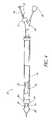
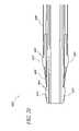
- FIG. 6illustrates a third exemplary probe constructed in accordance with the principles of the present invention.
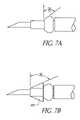
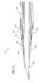
- FIGS. 7 , 7 A, and 7 Bare schematic illustrations of alternate embodiments of the tip of the probe of FIG. 6 marked to show dimensions.
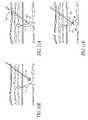
- FIGS. 8A-8Dillustrate use of the probe illustrated in FIG. 1 in performing a procedure according to the method of the present invention.
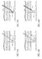
- FIGS. 9A-9Cillustrate the probe of FIG. 1 in performing a second exemplary procedure in accordance with the principles of the present invention.
- FIGS. 10A-10Eillustrate the use of the probe of FIG. 1 for performing a third exemplary procedure according to the principles of the present invention.
- FIGS. 11A-11Billustrate the use of the probe of FIG. 6 for performing a fourth exemplary procedure according to the present invention.
- FIGS. 12A-12Dillustrate the use of a trocar with a rigid probe having a pair of spaced-apart electrodes for endovascular treatment of a HAS in order to constrict the HAS in accordance with the principles of the present invention.
- FIGS. 13A-13Cillustrate the use of a rigid probe having a single electrode for penetrating and pinning a HAS in order to constrict the HAS in accordance with the principles of the present invention.
- FIGS. 14A-14Dillustrate the use of a flexible probe introduced through a percutaneous sheath performing an endovascular treatment of a HAS in order to constrict the HAS in accordance with the principles of the present invention.
- FIGS. 15A-15Fillustrate the use of a small gage needle for placement of a guidewire and introduction of a two electrode probe with sliding external sheath over the guidewire in order to constrict the HAS in accordance with the principles of the present invention.
- FIGS. 16A and 16Billustrate a particular method for introducing a two electrode probe to the fascial layer and moving the probe until the defect in the fascial layer is detected and the probe is introduced through the defect to a location adjacent to a HAS in order to constrict the HAS in accordance with the principles of the present invention.
- FIGS. 17 and 18illustrate an electrode configuration suitable for use with various embodiments of the electrode probe disclosed herein.
- FIGS. 19 and 20illustrate another electrode configuration suitable for use with various embodiments of the electrode probe disclosed herein.
- FIGS. 21 and 22illustrate another electrode configuration suitable for use with various embodiments of the electrode probe disclosed herein.
- FIG. 23illustrates another electrode configuration suitable for use with various embodiments of the electrode probe disclosed herein.
- FIG. 24illustrates a resistive-heater tip usable in place of, or in addition to, the electrode(s) of any of the various probes disclosed herein.
- FIGS. 17 through 23are drawn to scale.
- a first exemplary system 10 constructed in accordance with the principles of the present inventioncomprises a bipolar electrode probe 12 and a radiofrequency (RF) electrosurgical power supply 14 .
- a bipolar electrode probe 12comprises a flexible shaft 16 having a distal end 18 and a proximal end 20 having a Y-shaped connector hub 22 attached thereto.
- a first electrode 24 and second electrode 26are mounted on the shaft 16 near the distal end 18 .
- the shaft 16has a central lumen which extends over its entire length (from the proximal end to the distal tip), and the lumen may be connected, typically via a luer connector (now shown) through a flexible line 30 having a luer or other connector hub 32 at its other end which can be connected to a source of infusion fluid, typically saline.
- the electrodes 24 and 26may be connected to the radiofrequency electrosurgical power supply 14 through a cable 34 and connector 36 .
- the connections to the electrodes 24 and 26are isolated so that the two electrodes may be connected to opposite poles of the power supply 14 , in the case of a bipolar configuration.
- an external sheath 38is slidably received over the exterior of the flexible shaft 16 .
- the sheathprovides external stiffening of the flexible shaft 16 when desired.
- the sheathmay include a handle or grip 40 near a proximal end thereof to facilitate its manipulation. Additionally, the sheath 38 may be sharpened at its distal end to allow for improved tissue penetration.
- the external sheath 38may allow selective stiffening of an otherwise flexible shaft 16 .
- the sheath 38will be placed in a forwardly advanced position to provide a rigid structure which is more controllable during subcutaneous manipulation and advancement over a guidewire or through a cannula where flexibility is not required and can even be a disadvantage.
- the external sheath 38can be partially or fully withdrawn to expose a distal length of the flexible shaft 16 to allow further advancement into the HAS or to simply remove the rigid structure during treatment or while external compression is used to manipulate the device tip into contact with the HAS wall.
- the first and second electrodes 24 and 26are illustrated as generally spherical or toroidal electrodes, as defined above.
- the flexible body 16which is typically formed from a polymer or other electrically insulating material, acts to isolate the electrodes and provide the desired axial spacing, also as discussed above. While the electrodes are illustrated as spherical or toroidal, a variety of other specific designs may used under different circumstances, as will be discussed below.
- a first specific electrode designcomprising a first electrode 44 in the form of a ring which is typically toroidal with a very flat surface and a second electrode 46 which is generally spherical or toroidal, as defined above.
- the first and second electrodesare disposed at the distal end of a polymeric shaft or body 48 , in a variety of ways.
- a polymeric shaft or body 48can be attached through the center lumen of the shaft.
- the opening formed in the center of the elementsis approximately centered on the longitudinal axis of the shaft. Other embodiments are described below.
- a trocar or needle 50is received in the central lumen of the body 48 .
- the trocar 50has a sharpened distal end or tip 52 so that it may be introduced directly into solid tissue, for example for accessing a HAS in the procedures described below.
- Electrodes 44 and 46are spaced-apart by a spacer 54 located therebetween and isolated by a polymeric tube (not shown) insulating the entire length under the proximal electrode 44 .
- the trocaris preferably removable, leaving the structure illustrated in FIG. 3 .
- At least one temperature sensor, typically a thermocouple or a thermistor 56will be provided on or near either of the electrodes. As illustrated, it is at the proximal end of the first electrode 44 .
- the temperature sensoris connected to the power supply through wires 58 .
- the first and second electrodesare connected to a power supply through isolated wires 60 and 62 .
- the electrode(s)may run the entire length of the device, thus eliminating the need for separate connecting wires.
- the probe body or shaft 48 and the trocar 50will be rigid to facilitate advancement of the sharpened tip of trocar 50 through tissue.
- at least the trocarwill be rigid since it will most often be composed of stainless steel or another metal.
- the probe body 48will also be rigid or stiffened by reinforcing elements.
- the trocar 50may have an internal lumen and a port or opening 64 at its distal end, typically to permit the detection of flashback upon HAS entry, optional introduction over a guidewire and/or the delivery of saline or other physiologically acceptable fluid to the treatment region during a procedure.
- the flexible body or shaft 16has lumen 70 shown in a broken-away portion thereof.
- the lumen 70carries a tube 72 which is connected to the second electrode 26 .
- An insulating region 74is provided between the second electrode 26 and the first electrode 24 , and a wire 78 is connected to the second electrode and runs proximally through the probe and to the electrical connector 36 .
- a second wire(not shown) is connected to the first electrode 24 and also runs proximally to the connector 36 .
- temperature sensor wiresare connected to the thermocouple, thermistor, or other thermosensor 80 and run through the flexible body 16 to the connector 36 .
- the inner shaft 72is preferably formed from a structurally reinforced material such as braided polyimide, while the outer shaft may be formed from a polymeric extrusion such as thermoplastic polyester elastomers, polyimide, nylons, PEEK, polyether-block co-polyamide polymers, and the like.
- the connecting tube 30may be formed from polyvinylchloride (PVC) or other suitable polymer and have a luer fitting 32 at both free ends. Tube 30 may be connected to the hub 22 by a luer 31 .
- spherical or toroidal electrodeswill typically have a diameter D in a plane which is transversed to the axis of the catheter body in the range from 1 mm to 3 mm.
- the flexible probe bodywill have a diameter d which is smaller than that of the electrodes, typically being in the range from 0.5 mm to 2.5 mm.
- the distance t between the inner edges of the spherical electrodeswill be in the range from 1 mm to 5 mm. As shown in FIG.
- the distal electrodemay have a taper in the distal direction providing an entry angle ⁇ to the electrode improving the ability to advance the probe through tissue and/or through the wall of an HAS.
- the entry angle ⁇ of the spherical or toroidal electrodewill be in the range from 0° to 90°, typically being in the range from 0° to 60°.
- probe body 92may be rigid or flexible and will, as with prior embodiments, have a lumen therethrough. Within the lumen, a trocar 94 having a sharpened tip 96 will be removably received within the lumen. A first spherical or toroidal electrode 98 is integral or attached to the distal end of the probe body 92 . The trocar 94 acts as the second electrode, and is insulated from the remaining components by a sleeve 100 .
- the sleeve 100may run the entire length of the device to provide insulation.
- the first electrode 98may also run the entire length over the sleeve 100 and within the probe body 92 to provide for electrical connection back to a proximal hub (not shown).
- a thermocouple 104 or other temperature sensormay be connected through wires (not shown) which run the length of the probe.
- the apparatus of FIG. 6can provide for the introduction of saline or other physiologically acceptable fluid through a multi-arm hub (not shown).
- the fluidcan be delivered through the lumen running through the trocar 94 and/or through an annular space between the outer surface of sleeve 100 and the inner surface of the electrode 98 .
- the exposed portion of trocar 94has a length l 1 in the range from 1 mm to 10 mm, and a diameter d in the range from 0.5 mm to 1 mm.
- the proximal most end of the exposed trocar 94is spaced apart from a spherical or toroidal electrode 108 by a distance l 2 in the range from 1 mm to 5 mm.
- the diameter D of the spherical or toroidal electrodeis generally the same as described above, typically being in the range from 1 mm to 3 mm. As shown in FIG.
- the generally spherical or toroidal electrodemay have a taper in the distal direction providing an entry angle ⁇ to the electrode improving the ability to advance the probe through tissue and/or through the wall of an HAS.
- the entry angle ⁇is generally the same as described above being in the range from 0° to 90°, typically being in the range from 0° to 60°.
- the space between the electrodesmay be tapered in the distal direction providing an entry angle ⁇ and transition element 95 improving the ability to advance the probe through tissue and/or through the wall of an HAS.
- the entry angle ⁇is generally the same as described above being in the range from 0° to 90°, typically being in the range from 0° to 60°.
- FIGS. 8A-8Duse of the probe of the present invention for performing constriction of a perforator vein P or other HAS is illustrated. While the use is described in connection with the rigid bipolar electrode probe 12 , the method will generally apply to the other embodiments described herein.
- the perforator veinconnects the deep venous system DV to the superficial venous system SV, as generally shown in each of the figures.
- Access to the perforator vein P or other HASmay be achieved with a conventional needle and cannula assembly 110 , as illustrated. Alternatively, direct access may be achieved relying on the exposed trocar tip 52 or 96 ( FIGS. 2 or 6 ). As illustrated in FIGS.
- cannula 110is introduced through the skin to the target site, and a needle removed from the cannula, as shown in FIG. 8B .
- the probe 12may be introduced through the cannula to a site within the perforator vein P or other HAS, as shown in FIG. 8C .
- Energymay then be applied through the electrodes 24 and 26 until a desired degree of constriction has been achieved.
- bipolar RF energywill heat the tissue and/or HAS, temperature will monitored with a thermocouple on the probe, and the radiofrequency generator will modulate power to maintain the desired temperature.
- the treatmentcan be terminated and the probe and cannula removed, leaving a constricted region CON in the perforator vein PV as shown in FIG. 8D .
- the treatment protocol illustrated in FIGS. 8A-8Dis generally referred to herein as endovascular, i.e., within the HAS. While the use is described in connection with the rigid bipolar electrode probe 12 , the method will generally apply to the other embodiments described herein. Radiofrequency probe 12 may also be used to perform extravascular treatment, as illustrated in FIGS. 9A-9C . Access with the assembly 110 may be achieved as generally described before, except that the perforator vein P or other HAS is not necessarily penetrated. Alternatively, direct access may be achieved relying on the exposed trocar tip 52 or 96 ( FIGS. 2 or 6 ).
- the bipolar electrode probe 12is introduced through the cannula 110 and the electrodes 24 and 26 are positioned adjacent the exterior of the vein or other HAS.
- the electrodesare energized and the tissue heated sufficiently to constrict the walls of the vein or other HAS, without any penetration, with the resulting constriction shown in FIG. 9C .
- FIGS. 10A-10Ea third protocol using the bipolar electrode probe 12 for constricting the perforator vein P or other HAS is illustrated.
- the needle and cannula 110is introduced to fully penetrate the perforator vein P or other HAS so that the tip passes through the far side.
- the needleis removed and bipolar electric probe 12 introduced through a cannula, as shown generally in FIG. 10B .
- the probe 12is rigid but it could also have a flexible shaft. While the use is described in connection with passing the probe through a cannula, this method could alternatively be performed by “directly” penetrating the vein with a probe having a needle or trocar in a central lumen thereof as in FIG.
- FIG. 10CThe electrodes on the probe 12 are then energized as the probe is drawn back to contact the far side of the vein or other HAS, as shown in FIG. 10C .
- the vein or other HASis heated and collapsed as the probe 12 is continued to be drawn back through the HAS, as shown in FIG. 10D .
- the cannulais completely removed by this point.
- the perforator vein P or other HASis constricted, as shown in FIG. 10E .
- FIGS. 11A and 11Ba fourth protocol of the bipolar electrode probe 90 of FIG. 6 for treating a perforator vein P or other HAS will be described.
- the probe 90is introduced directly through tissue under ultrasonic guidance until the sharpened tip 96 contacts the exterior of the vein or other HAS.
- the surgeonadvances the sharpened tip 96 through the vein or other HAS so that the spherical or toroidal electrode 98 engages and collapses the vein or other HAS, as shown in FIG. 11B .
- the electrodes 94 and 98are then energized to heat and constrict the walls of the vein or other HAS.
- the areamay optionally be infused with saline or other physiologically acceptable fluid in order to enhance current flow, tissue heating, and HAS constriction. Hollow anatomical structure access may be confirmed by observation of flashback through a lumen of the system.
- FIGS. 12A-12Dit is also possible to introduce electrode structures on the exterior of a rigid or non-rigid probe “directly”. Direct access is achieved using probe 120 having a needle or trocar 122 in a central lumen thereof or having a sharpened distal electrode being rigidly fixed to the probe as in FIG. 6 .
- the needle or trocar 122has a sharpened distal tip 124 which allows direct penetration through the tissue until the sharpened tip 124 reaches the perforator vein P or other HAS. The sharpened tip 124 is then used to penetrate the HAS, as shown in FIG.
- the needle or trocar 122may then be retracted to within the probe 120 , and radiofrequency energy delivered through the electrodes 126 , as shown in FIG. 12C .
- the energycauses constriction CON of the perforator vein P or other HAS as shown in FIG. 12D .
- the probe 120may be withdrawn.
- the protocol illustrated in FIGS. 12A-12Dcould also be performed using a single polarity and/or electrode device. Additionally, the protocol illustrated could also be used in performing an extravascular procedure.
- a rigid probe 140 having a sharpened distal tip 142 and a single electrode 144may be introduced to directly access the perforator vein P or other HAS, as shown in FIG. 13A , and to penetrate and pin the vein, as shown in FIG. 13B .
- Sufficient manual forceis maintained on the probe 140 to collapse the perforator vein P or other HAS while energy is being delivered, as shown in FIG. 13B .
- the resultis a constriction CON in perforator vein P or other HAS when the procedure is terminated, as shown in FIG. 13C . While the use is described in connection with the rigid single polarity and/or electrode probe 140 , the method will generally apply to the other embodiments described herein.
- a conventional needle and cannula assembly 160 having a removable needle 162may be introduced to a perforator vein P or other HAS under ultrasound guidance.
- the cannula 160may be introduced into the perforator vein P or other HAS using the needle 162 , and the needle withdrawn, as shown in FIG. 14B .
- the needlemay be hollow in some embodiments.
- a flexible probe 170 having a pair of electrodes 172 at its distal endmay then be introduced through the cannula 160 .
- the probe 170with flexible and atraumatic tip, will align itself with the interior of the perforator vein P or other HAS lumen, as shown in FIG. 14C .
- the length of the flexible probeallows for distal advancement into the lumen after insertion.
- Energyis then delivered through the electrodes 172 to constrict CON the vein or other HAS as shown in FIG. 14D .
- the probe 170is then withdrawn into the cannula 160 , and the assembly withdrawn.
- Endovascular proceduresmay also be performed over a guidewire GW introduced through an introducer sheath, cannula, or catheter 180 which may be introduced over a needle (not shown) in a conventional manner.
- the guidewire GWmay be introduced directly through the needle. While the use is described in connection with a bipolar electrode probe, the method will generally apply to the other embodiments described herein.
- the needle 180is introduced so that its distal end 182 enters the lumen of the perforator vein P or other HAS, as shown in FIG. 15B .
- the guidewire GWis then introduced through the needle 180 , and the needle withdrawn, as shown in FIG.
- FIG. 15Cleaving the guidewire GW in place through the tissue, as shown in FIG. 15D .
- a combination flexible probe with rigid sliding external sheath 186is then introduced over the guidewire GW, as shown in FIG. 15E .
- the sliding external sheathmay be partially or fully retracted to expose a distal length of the flexible probe to allow for further advancement into the HAS or to simply remove the rigid structure during treatment (not shown).
- Radiofrequency energyis delivered through the electrodes 188 to constrict the perforator vein P or other HAS, as shown in FIG. 15F .
- the sheath and probe 186may then be withdrawn.
- the probe 186has a flexible shaft, but it could also be rigid.
- a probe 200may be introduced through overlying tissue until its distal tip 202 encounters the fascial layer F, as shown in FIG. 16A . Initially, as shown in broken line, the probe 200 will almost certainly encounter a region of the fascia remote from the defect D through which the perforator vein P or other HAS passes. By properly moving or “dottering” the tip 202 of the probe over the fascial layer, as shown in FIG.
- the probe 200will encounter the defect and pass therethrough. Once the distal end of the probe has passed through the defect, the electrodes 204 will be properly positioned adjacent the extravascular wall of the perforator vein P or other HAS, as shown in FIG. 16B . Additional manipulation, such as conical rotation of the probe 200 , may allow the perforator vein P or other HAS to become wrapped around the electrode portion of the probe 200 . Another form of manipulation may include using the probe 200 as a lever to press the perforator vein P or other HAS against the fascial layer from below. Radiofrequency energy can then be delivered to constrict the HAS. As with all previous protocols, the probe 200 may then be withdrawn after the treatment is complete. As illustrated, the probe 200 has a rigid shaft, but it could also be a flexible or combination flexible probe with sliding external rigid sheath. Additionally, while the use is described in connection with a bipolar electrode probe, the method will generally apply to the other embodiments described herein.
- FIGS. 17-18depict another electrode configuration 300 which can be used in any of the embodiments of the electrode probes 12 , 120 , 140 , etc. disclosed herein, or in any suitable electrode probe, or in any of the embodiments of the system 10 disclosed herein.
- An electrode probe employing the electrode configuration 300can be used in practicing any of the embodiments of the protocols disclosed herein, e.g., in practicing any of the treatment methods disclosed herein, and/or any one or more of the protocols depicted in FIGS. 8A-8D ; 9 A- 9 C; 10 A- 10 E; 11 A- 11 B; 12 A- 12 D; 13 A- 13 C; and/or 14 A- 14 D.
- the electrode configuration 300 of FIGS. 17-18can be generally similar to any of the electrode designs or configurations disclosed herein.
- the electrode configuration 300comprises a proximal electrode 302 and a distal electrode 304 which are separated by an electrically insulative spacer 306 .
- An electrically insulative layer 308extends proximally from the proximal electrode 302 .
- a trocar or needle 350is removably received within a lumen of the probe on which the electrodes 302 , 304 are mounted.
- the distal electrode 304has a distal taper 320 to ease insertion of the electrode 304 and probe through the patient's tissues.
- the taper 320comprises a truncated cone with a taper angle of 70 degrees referenced from a plane located distal of the electrodes and normal to the electrodes' center axis; however, in other embodiments the taper angle may be between 45 and 85 degrees.
- Proximal of the taper 320is a curved electrode surface 322 of the distal electrode 304 .
- the radius of the curved electrode surface 322is about 0.063 inches (in the sectional plane depicted in FIGS. 17-18 ); however, in other embodiments this radius may be between 0.040 and 0.080 inches.
- the proximal electrode 302also forms a curved electrode surface 330 .
- the radius of this curved electrode surface 330can be, in various embodiments, about 0.063 inches (in the sectional plane depicted in FIGS. 17-18 ), or between 0.040 and 0.080 inches.
- FIGS. 19-20depict another electrode configuration 400 which can be used in any of the embodiments of the electrode probes 12 , 120 , 140 , etc. disclosed herein, or in any suitable electrode probe, or in any of the embodiments of the system 10 disclosed herein.
- An electrode probe employing the electrode configuration 400can be used in practicing any of the embodiments of the protocols disclosed herein, e.g., in practicing any one or more of the protocols depicted in FIGS. 8A-8D ; 9 A- 9 C; 10 A- 10 E; 11 A- 11 B; 12 A- 12 D; 13 A- 13 C; and/or 14 A- 14 D.
- the electrode configuration 400 of FIGS. 19-20can be generally similar to any of the electrode designs or configurations disclosed herein.
- the electrode configuration 400comprises a proximal electrode 402 and a distal electrode 404 which are separated by an electrically insulative spacer 406 .
- An electrically insulative layer 408extends proximally from the proximal electrode 402 .
- a trocar or needle 450is removably received within a lumen of the probe on which the electrodes 402 , 404 are mounted.
- Each of the electrodes 402 , 404has a corresponding curved, tapered outer surface 422 , 424 to ease insertion of the electrodes 402 , 404 and probe through the patient's tissues.
- Each of the outer surfaces of the electrodes 402 , 404is tapered in that the diameter of each outer surface 422 , 424 is greater at the proximal end than at the distal end thereof.
- the outer surface 422 of the proximal electrode 402tapers from a diameter of 0.075 inches at its proximal end to a diameter of 0.068 inches at its distal end, over an exposed axial length of 0.035 inches, while the outer surface 422 has a maximum diameter of 0.077 inches between the distal and proximal ends. These dimensions may vary as needed in other embodiments.
- the outer surface 424 of the distal electrode 404tapers from a diameter of 0.0552 inches at its proximal end to a diameter of 0.045 inches at its distal end, over an exposed axial length of 0.047 inches, while the outer surface 424 has a maximum diameter of 0.0565 inches between the distal and proximal ends. These dimensions may vary as needed in other embodiments.
- the radius of the outer surface 422 of the proximal electrode 402is 0.063 inches in the sectional plane depicted in FIGS. 19-20
- the radius of the outer surface 424 of the distal electrode 404is 0.113 inches in the sectional plane depicted in FIGS. 19-20 .
- the electrically insulative spacer 406is tapered to provide a smooth graduation between the proximal electrode 402 and the distal electrode 404 .
- the inner lumen diameter of the distal electrode 404is 0.0370 inches.
- the exposed surface area of the outer surface 422 of the proximal electrode 402is approximately equal to the exposed surface area of the outer surface 424 of the distal electrode 404 .
- FIGS. 21-22depict another electrode configuration 500 which can be used in any of the embodiments of the electrode probes 12 , 120 , 140 , etc. disclosed herein, or in any suitable electrode probe, or in any of the embodiments of the system 10 disclosed herein.
- An electrode probe employing the electrode configuration 500can be used in practicing any of the embodiments of the protocols disclosed herein, e.g., in practicing any one or more of the protocols depicted in FIGS. 8A-8D ; 9 A- 9 C; 10 A- 10 E; 11 A- 11 B; 12 A- 12 D; 13 A- 13 C; and/or 14 A- 14 D.
- the electrode configuration 500 of FIGS. 21-22can be generally similar to any of the electrode designs or configurations disclosed herein.
- the electrode configuration 500comprises a proximal electrode 502 and a distal electrode 504 which are separated by an electrically insulative spacer 506 .
- An electrically insulative layer 508extends proximally from the proximal electrode 502 .
- a trocar or needle 550is removably received within a lumen of the probe on which the electrodes 502 , 504 are mounted.
- Each of the electrodes 502 , 504has a corresponding tapered outer surface 522 , 524 to ease insertion of the electrodes 502 , 504 and probe through the patient's tissues.
- Each of the outer surfaces of electrodes 502 , 504is tapered in that the diameter of each outer surface 522 , 524 is greater at the proximal end than at the distal end thereof.
- the outer surfaces 522 , 524are “flat tapered” in that each defines a truncated cone or frustum with a taper angle of 84 degrees referenced from a plane located distal of the electrodes and normal to the electrodes' center axis. In other embodiments, this taper angle can vary between 70 and 88 degrees.
- the outer surface 522 of the proximal electrode 502tapers from a diameter of 0.075 inches at its proximal end to a diameter of 0.068 inches at its distal end, over an exposed axial length of 0.035 inches. These dimensions may vary as needed in other embodiments.
- the outer surface 524 of the distal electrode 504tapers from a diameter of 0.0552 inches at its proximal end to a diameter of 0.045 inches at its distal end, over an exposed axial length of 0.047 inches. These dimensions may vary as needed in other embodiments.
- the electrically insulative spacer 506is tapered to provide a smooth graduation between the proximal electrode 502 and the distal electrode 504 .
- the inner lumen diameter of the distal electrode 504is 0.0370 inches.
- the exposed surface area of the outer surface 522 of the proximal electrode 502is approximately equal to the exposed surface area of the outer surface 524 of the distal electrode 504 .
- FIG. 23depicts another electrode configuration 600 which can be used in any of the embodiments of the electrode probes 12 , 120 , 140 , etc. disclosed herein, or in any suitable electrode probe, or in any of the embodiments of the system 10 disclosed herein.
- An electrode probe employing the electrode configuration 600can be used in practicing any of the embodiments of the protocols disclosed herein, e.g., in practicing any one or more of the protocols depicted in FIGS. 8A-8D ; 9 A- 9 C; 10 A- 10 E; 11 A- 11 B; 12 A- 12 D; 13 A- 13 C; and/or 14 A- 14 D.
- the electrode configuration 600 of FIG. 23can be generally similar to any of the electrode designs or configurations disclosed herein.
- the electrode configuration 600comprises a proximal electrode 602 and a distal electrode 604 which are separated by an electrically insulative spacer 606 .
- An electrically insulative layer 608extends proximally from the proximal electrode 602 .
- the distal electrode 604is integrally formed with a sharp entry tip 660 which extends distally from the distal end of the distal electrode 604 .
- the entry tip 660is appropriately tapered and sharpened to facilitate passage of the electrodes 602 , 604 and probe through the tissues of the patient.
- the outer surface 662 of the entry tipmay be electrically insulated to isolate the function of the distal electrode 604 to the desired region.
- Each of the electrodes 602 , 604preferably has a corresponding exposed, curved, tapered outer surface 622 , 624 to further ease insertion of the electrodes 602 , 604 and probe through the patient's tissues.
- Each of the outer surfaces of electrodes 602 , 604is tapered in that the diameter of each outer surface 622 , 624 is greater at the proximal end than at the distal end thereof.
- the electrodes 602 , 604 and outer surfaces 622 , 624 thereofhave shapes and dimensions which are similar to those of the electrodes 402 , 404 (and the outer surfaces 422 , 424 thereof) of the configuration 400 shown in FIGS. 19-20 .
- the electrodes 602 , 604 and outer surfaces 622 , 624 thereofcan take on other suitable shapes and dimensions.
- the shapes and dimensions of the electrodes 502 , 504 (and the outer surfaces 522 , 524 thereof) of the configuration 500 shown in FIGS. 21-22may be employed as an alternative.
- the electrically insulative spacer 606is tapered to provide a smooth graduation between the proximal electrode 602 and the distal electrode 604 .
- the inner lumen diameter of the distal electrode 604is 0.0370 inches.
- the exposed surface area of the outer surface 622 of the proximal electrode 602is approximately equal to the exposed surface area of the outer surface 624 of the distal electrode 604 .
- FIG. 24depicts a resistive-element tip 700 which can be used in any of the embodiments of the electrode probes 12 , 120 , 140 , etc. disclosed herein, in place of (or in addition to) the electrodes.
- the tip 700comprises a resistive-element heater 702 mounted on a distal section 704 of the probe.
- the distal section 704 with heating element 702may be tapered or cylindrical or tapered distally and cylindrical proximally.
- the heater 702is heated by passing electrical current therethrough and the hot heater 702 can be used to heat the inner lumen of a vein to close the vein.
- a probe employing the resistive-element tip 700can be used in practicing any of the embodiments of the protocols disclosed herein, e.g., in practicing any one or more of the protocols depicted in FIGS. 8A-8D ; 9 A- 9 C; 10 A- 10 E; 11 A- 11 B; 12 A- 12 D; 13 A- 13 C; and/or 14 A- 14 D, with the exception that thermal energy is applied via the resistive-element tip 700 instead of RF power applied via electrodes.
- the resistive-element heater 702can comprise a simple coil of resistive-heating material or wire, or a series of axially adjacent, separately operable coils. Such separate coils can be operated sequentially or in overlapping sequential groups, or in a fixed subset to vary the treatment length and/or minimize the power requirements of the heater. Each coil can have a separate temperature sensor to facilitate such separate operation and control.
- the structure and/or operation of the heater 702can be similar to any of the various embodiments of resistive elements or heaters, and/or modes of operation thereof, disclosed in U.S. Provisional Application No. 60/613,415, filed Sep. 27, 2004, titled RESISTIVE ELEMENT SYSTEM. The entire disclosure of the above-mentioned provisional application is hereby incorporated by reference herein and made a part of this specification.
- a trocar or needle 750is removably received (or, alternatively, fixedly received) within a lumen of the probe on which the heater 702 is mounted.
Landscapes
- Health & Medical Sciences (AREA)
- Surgery (AREA)
- Engineering & Computer Science (AREA)
- Life Sciences & Earth Sciences (AREA)
- Biomedical Technology (AREA)
- Molecular Biology (AREA)
- Nuclear Medicine, Radiotherapy & Molecular Imaging (AREA)
- Plasma & Fusion (AREA)
- Physics & Mathematics (AREA)
- Heart & Thoracic Surgery (AREA)
- Medical Informatics (AREA)
- Otolaryngology (AREA)
- Animal Behavior & Ethology (AREA)
- General Health & Medical Sciences (AREA)
- Public Health (AREA)
- Veterinary Medicine (AREA)
- Cardiology (AREA)
- Surgical Instruments (AREA)
Abstract
Description
Claims (22)
Priority Applications (3)
| Application Number | Priority Date | Filing Date | Title |
|---|---|---|---|
| US11/197,849US7625372B2 (en) | 2005-02-23 | 2005-08-05 | Methods and apparatus for coagulating and/or constricting hollow anatomical structures |
| US12/626,569US8361061B2 (en) | 2005-02-23 | 2009-11-25 | Methods and apparatus for coagulating and/or constricting hollow anatomical structures |
| US13/723,464US8795266B2 (en) | 2005-02-23 | 2012-12-21 | Methods and apparatus for coagulating and/or constricting hollow anatomical structures |
Applications Claiming Priority (2)
| Application Number | Priority Date | Filing Date | Title |
|---|---|---|---|
| US65603605P | 2005-02-23 | 2005-02-23 | |
| US11/197,849US7625372B2 (en) | 2005-02-23 | 2005-08-05 | Methods and apparatus for coagulating and/or constricting hollow anatomical structures |
Related Child Applications (1)
| Application Number | Title | Priority Date | Filing Date |
|---|---|---|---|
| US12/626,569ContinuationUS8361061B2 (en) | 2005-02-23 | 2009-11-25 | Methods and apparatus for coagulating and/or constricting hollow anatomical structures |
Publications (2)
| Publication Number | Publication Date |
|---|---|
| US20060189979A1 US20060189979A1 (en) | 2006-08-24 |
| US7625372B2true US7625372B2 (en) | 2009-12-01 |
Family
ID=35395689
Family Applications (3)
| Application Number | Title | Priority Date | Filing Date |
|---|---|---|---|
| US11/197,849Active2027-06-03US7625372B2 (en) | 2005-02-23 | 2005-08-05 | Methods and apparatus for coagulating and/or constricting hollow anatomical structures |
| US12/626,569Expired - LifetimeUS8361061B2 (en) | 2005-02-23 | 2009-11-25 | Methods and apparatus for coagulating and/or constricting hollow anatomical structures |
| US13/723,464Expired - LifetimeUS8795266B2 (en) | 2005-02-23 | 2012-12-21 | Methods and apparatus for coagulating and/or constricting hollow anatomical structures |
Family Applications After (2)
| Application Number | Title | Priority Date | Filing Date |
|---|---|---|---|
| US12/626,569Expired - LifetimeUS8361061B2 (en) | 2005-02-23 | 2009-11-25 | Methods and apparatus for coagulating and/or constricting hollow anatomical structures |
| US13/723,464Expired - LifetimeUS8795266B2 (en) | 2005-02-23 | 2012-12-21 | Methods and apparatus for coagulating and/or constricting hollow anatomical structures |
Country Status (1)
| Country | Link |
|---|---|
| US (3) | US7625372B2 (en) |
Cited By (7)
| Publication number | Priority date | Publication date | Assignee | Title |
|---|---|---|---|---|
| US7824408B2 (en) | 2004-08-05 | 2010-11-02 | Tyco Healthcare Group, Lp | Methods and apparatus for coagulating and/or constricting hollow anatomical structures |
| US7828793B2 (en) | 2005-07-21 | 2010-11-09 | Tyco Healthcare Group, Lp | Methods for treating a hollow anatomical structure |
| US20110282342A1 (en)* | 2010-05-10 | 2011-11-17 | Giovanni Leo | Irrigated finned ablation head |
| US8361061B2 (en) | 2005-02-23 | 2013-01-29 | Covidien Lp | Methods and apparatus for coagulating and/or constricting hollow anatomical structures |
| US8936631B2 (en) | 2010-01-04 | 2015-01-20 | Covidien Lp | Apparatus and methods for treating hollow anatomical structures |
| US9839378B2 (en) | 2007-02-06 | 2017-12-12 | Medtronic Minimed, Inc. | Optical systems and methods for ratiometric measurement of blood glucose concentration |
| US10357305B2 (en) | 2014-03-26 | 2019-07-23 | Venclose, Inc. | Venous disease treatment |
Families Citing this family (43)
| Publication number | Priority date | Publication date | Assignee | Title |
|---|---|---|---|---|
| US6689131B2 (en) | 2001-03-08 | 2004-02-10 | Tissuelink Medical, Inc. | Electrosurgical device having a tissue reduction sensor |
| ES2306706T3 (en) | 2000-03-06 | 2008-11-16 | Salient Surgical Technologies, Inc. | FLUID SUPPLY SYSTEM AND CONTROLLER FOR ELECTROCHURGICAL DEVICES. |
| US6953461B2 (en) | 2002-05-16 | 2005-10-11 | Tissuelink Medical, Inc. | Fluid-assisted medical devices, systems and methods |
| US8048070B2 (en) | 2000-03-06 | 2011-11-01 | Salient Surgical Technologies, Inc. | Fluid-assisted medical devices, systems and methods |
| US7811282B2 (en) | 2000-03-06 | 2010-10-12 | Salient Surgical Technologies, Inc. | Fluid-assisted electrosurgical devices, electrosurgical unit with pump and methods of use thereof |
| US6558385B1 (en) | 2000-09-22 | 2003-05-06 | Tissuelink Medical, Inc. | Fluid-assisted medical device |
| AU2002357166A1 (en) | 2001-12-12 | 2003-06-23 | Tissuelink Medical, Inc. | Fluid-assisted medical devices, systems and methods |
| WO2004039416A2 (en) | 2002-10-29 | 2004-05-13 | Tissuelink Medical, Inc. | Fluid-assisted electrosurgical scissors and methods |
| US8257411B2 (en)* | 2003-09-30 | 2012-09-04 | Biolitec Pharma Marketing Ltd | Method for treatment of varices |
| US7727232B1 (en) | 2004-02-04 | 2010-06-01 | Salient Surgical Technologies, Inc. | Fluid-assisted medical devices and methods |
| CA2577986A1 (en)* | 2004-09-01 | 2006-03-09 | Jms Co., Ltd. | Varix treatment system |
| WO2008141241A1 (en) | 2007-05-10 | 2008-11-20 | Glumetrics, Inc. | Equilibrium non-consuming fluorescence sensor for real time intravascular glucose measurement |
| JP5631215B2 (en) | 2007-11-21 | 2014-11-26 | メドトロニック ミニメド インコーポレイテッド | Blood sugar management maintenance system |
| WO2009129186A2 (en)* | 2008-04-17 | 2009-10-22 | Glumetrics, Inc. | Sensor for percutaneous intravascular deployment without an indwelling cannula |
| US20100047210A1 (en)* | 2008-08-25 | 2010-02-25 | Medtronic Vascular, Inc. | Systems and Methods for Positioning of Needles and Other Devices Within Body Tissue |
| WO2011041546A1 (en) | 2009-09-30 | 2011-04-07 | Glumetrics, Inc. | Sensors with thromboresistant coating |
| US8467843B2 (en) | 2009-11-04 | 2013-06-18 | Glumetrics, Inc. | Optical sensor configuration for ratiometric correction of blood glucose measurement |
| EP2582306B1 (en) | 2010-06-15 | 2023-03-29 | Avenu Medical, Inc. | Systems and methods for creating arteriovenous (av) fistulas |
| WO2011159825A1 (en) | 2010-06-15 | 2011-12-22 | Caymus Medical, Inc. | Intravascular arterial to venous anastomosis and tissue welding catheter |
| EP4032486A1 (en) | 2010-11-16 | 2022-07-27 | TVA Medical, Inc. | Devices for forming a fistula |
| US20130184551A1 (en)* | 2012-01-13 | 2013-07-18 | Jude V. Paganelli | Neuromonitoring dilator |
| JP6182545B2 (en)* | 2012-02-08 | 2017-08-16 | アベヌ メディカル インコーポレイテッドAvenu Medical,Inc. | Intravascular arteriovenous anastomosis and tissue junction catheter |
| US9486276B2 (en) | 2012-10-11 | 2016-11-08 | Tva Medical, Inc. | Devices and methods for fistula formation |
| US9439710B2 (en) | 2012-11-14 | 2016-09-13 | Avenu Medical, Inc. | Intravascular arterial to venous anastomosis and tissue welding catheter |
| US9839478B2 (en)* | 2012-12-22 | 2017-12-12 | Kai Meng | Method for treating lower extremity varicose vein combined ultrasonic wave and microwave |
| US9717551B2 (en)* | 2013-02-21 | 2017-08-01 | Carefusion 2200, Inc. | Intravertebral tissue ablation device and method |
| CN105228683B (en) | 2013-03-14 | 2022-06-10 | Tva医疗公司 | Fistula-forming device and method for forming fistula |
| EP2967746B1 (en)* | 2013-03-15 | 2019-05-08 | Baylis Medical Company Inc. | Electrosurgical device having a distal aperture |
| CA3220441A1 (en) | 2013-03-15 | 2015-09-17 | Boston Scientific Medical Device Limited | Electrosurgical device having a distal aperture |
| US10070866B1 (en) | 2013-08-01 | 2018-09-11 | Avenu Medical, Inc. | Percutaneous arterial to venous anastomosis clip application catheter system and methods |
| US10772672B2 (en) | 2014-03-06 | 2020-09-15 | Avenu Medical, Inc. | Systems and methods for percutaneous access and formation of arteriovenous fistulas |
| US10695534B2 (en) | 2014-03-14 | 2020-06-30 | Tva Medical, Inc. | Fistula formation devices and methods therefor |
| WO2016033374A1 (en) | 2014-08-27 | 2016-03-03 | Tva Medical, Inc. | Cryolipopysis devices and methods therefor |
| US10603040B1 (en) | 2015-02-09 | 2020-03-31 | Tva Medical, Inc. | Methods for treating hypertension and reducing blood pressure with formation of fistula |
| CN108366822B (en) | 2015-08-21 | 2021-02-19 | 艾凡诺医疗公司 | System and method for percutaneous arteriovenous fistula |
| CN114042224B (en) | 2016-01-15 | 2024-09-17 | Tva医疗公司 | Device and method for advancing a wire |
| US10874422B2 (en) | 2016-01-15 | 2020-12-29 | Tva Medical, Inc. | Systems and methods for increasing blood flow |
| WO2017124062A1 (en) | 2016-01-15 | 2017-07-20 | Tva Medical, Inc. | Devices and methods for forming a fistula |
| JP7219090B2 (en) | 2016-01-15 | 2023-02-07 | ティーブイエー メディカル, インコーポレイテッド | Systems and methods for gluing vessels |
| CN109715097A (en) | 2016-07-29 | 2019-05-03 | 库克医学技术有限责任公司 | Electrosurgery unit with the single conductive tubular element for entering anatomical structure |
| CN109982652B (en) | 2016-09-25 | 2022-08-05 | Tva医疗公司 | Vascular stent device and method |
| CA3041114A1 (en)* | 2016-11-28 | 2018-05-31 | Dfine, Inc. | Tumor ablation devices and related methods |
| US11497507B2 (en) | 2017-02-19 | 2022-11-15 | Orpheus Ventures, Llc | Systems and methods for closing portions of body tissue |
Citations (83)
| Publication number | Priority date | Publication date | Assignee | Title |
|---|---|---|---|---|
| US373399A (en) | 1887-11-15 | hamilton | ||
| US452220A (en) | 1891-05-12 | gunning | ||
| US833759A (en) | 1905-07-27 | 1906-10-23 | John D Sourwine | Surgical instrument. |
| US1943543A (en) | 1932-06-21 | 1934-01-16 | William J Mcfadden | Surgical instrument |
| US2022065A (en) | 1932-07-07 | 1935-11-26 | Frederick C Wappler | Therapeutic applicator device |
| US3100489A (en) | 1957-09-30 | 1963-08-13 | Medtronic Inc | Cautery device |
| US3230957A (en) | 1960-03-23 | 1966-01-25 | Philips Corp | High frequency therapeutic apparatus |
| US3301258A (en) | 1963-10-03 | 1967-01-31 | Medtronic Inc | Method and apparatus for treating varicose veins |
| US3313293A (en)* | 1964-01-13 | 1967-04-11 | Hewlett Packard Co | Multi-electrode needle |
| US3920021A (en) | 1973-05-16 | 1975-11-18 | Siegfried Hiltebrandt | Coagulating devices |
| US4481953A (en) | 1981-11-12 | 1984-11-13 | Cordis Corporation | Endocardial lead having helically wound ribbon electrode |
| US4532924A (en) | 1980-05-13 | 1985-08-06 | American Hospital Supply Corporation | Multipolar electrosurgical device and method |
| US4548207A (en) | 1982-11-17 | 1985-10-22 | Mentor O & O, Inc. | Disposable coagulator |
| US4561445A (en)* | 1983-05-25 | 1985-12-31 | Joseph J. Berke | Elongated needle electrode and method of making same |
| US4643186A (en) | 1985-10-30 | 1987-02-17 | Rca Corporation | Percutaneous transluminal microwave catheter angioplasty |
| US4674499A (en) | 1980-12-08 | 1987-06-23 | Pao David S C | Coaxial bipolar probe |
| US4682596A (en) | 1984-05-22 | 1987-07-28 | Cordis Corporation | Electrosurgical catheter and method for vascular applications |
| US4765331A (en) | 1987-02-10 | 1988-08-23 | Circon Corporation | Electrosurgical device with treatment arc of less than 360 degrees |
| US4832051A (en) | 1985-04-29 | 1989-05-23 | Symbion, Inc. | Multiple-electrode intracochlear device |
| US4966597A (en) | 1988-11-04 | 1990-10-30 | Cosman Eric R | Thermometric cardiac tissue ablation electrode with ultra-sensitive temperature detection |
| US4998933A (en) | 1988-06-10 | 1991-03-12 | Advanced Angioplasty Products, Inc. | Thermal angioplasty catheter and method |
| US5122137A (en) | 1990-04-27 | 1992-06-16 | Boston Scientific Corporation | Temperature controlled rf coagulation |
| US5281216A (en) | 1992-03-31 | 1994-01-25 | Valleylab, Inc. | Electrosurgical bipolar treating apparatus |
| US5281218A (en) | 1992-06-05 | 1994-01-25 | Cardiac Pathways Corporation | Catheter having needle electrode for radiofrequency ablation |
| US5334193A (en) | 1992-11-13 | 1994-08-02 | American Cardiac Ablation Co., Inc. | Fluid cooled ablation catheter |
| US5403311A (en)* | 1993-03-29 | 1995-04-04 | Boston Scientific Corporation | Electro-coagulation and ablation and other electrotherapeutic treatments of body tissue |
| US5437664A (en) | 1994-01-18 | 1995-08-01 | Endovascular, Inc. | Apparatus and method for venous ligation |
| US5556396A (en) | 1994-01-18 | 1996-09-17 | Endovascular, Inc. | Method for tubal electroligation |
| US5562703A (en) | 1994-06-14 | 1996-10-08 | Desai; Ashvin H. | Endoscopic surgical instrument |
| US5658282A (en) | 1994-01-18 | 1997-08-19 | Endovascular, Inc. | Apparatus for in situ saphenous vein bypass and less-invasive varicose vein treatment |
| US5695495A (en) | 1995-11-20 | 1997-12-09 | Ellman; Alan G. | Electrosurgical electrode for sclerotherapy |
| US5700262A (en) | 1995-10-16 | 1997-12-23 | Neuro Navigational, L.L.C. | Bipolar electrode with fluid channels for less invasive neurosurgery |
| US5709224A (en) | 1995-06-07 | 1998-01-20 | Radiotherapeutics Corporation | Method and device for permanent vessel occlusion |
| WO1998009575A1 (en) | 1996-09-06 | 1998-03-12 | Mentor Ophthalmics, Inc. | Bipolar electrosurgical device |
| US5734903A (en) | 1994-05-13 | 1998-03-31 | Apple Computer, Inc. | System and method for object oriented message filtering |
| US5752951A (en) | 1996-07-02 | 1998-05-19 | Yanik; Gary W. | Shielded monopolar electrosurgical apparatus |
| US5766167A (en) | 1993-12-17 | 1998-06-16 | United States Surgical Corporation | Monopolar electrosurgical Instruments |
| US5810802A (en) | 1994-08-08 | 1998-09-22 | E.P. Technologies, Inc. | Systems and methods for controlling tissue ablation using multiple temperature sensing elements |
| US5893849A (en) | 1992-12-17 | 1999-04-13 | Megadyne Medical Products, Inc. | Cautery medical instrument |
| US5897553A (en) | 1995-11-02 | 1999-04-27 | Medtronic, Inc. | Ball point fluid-assisted electrocautery device |
| US5925045A (en) | 1993-11-10 | 1999-07-20 | Mentor Corporation | Bipolar electrosurgical instrument |
| US5954715A (en) | 1997-06-05 | 1999-09-21 | Adiana, Inc. | Method and apparatus for tubal occlusion |
| US5964754A (en) | 1996-05-24 | 1999-10-12 | Sulzer Osypka Gmbh | Device for perforating the heart wall |
| US5976131A (en) | 1990-03-13 | 1999-11-02 | The Regents Of The University At California | Detachable endovascular occlusion device activated by alternating electric current |
| US6003397A (en) | 1995-10-09 | 1999-12-21 | Asmo Co., Ltd. | Rotary output transmitting structure with a slidable washer |
| US6004319A (en) | 1995-06-23 | 1999-12-21 | Gyrus Medical Limited | Electrosurgical instrument |
| US6014589A (en) | 1997-11-12 | 2000-01-11 | Vnus Medical Technologies, Inc. | Catheter having expandable electrodes and adjustable stent |
| US6030382A (en) | 1994-08-08 | 2000-02-29 | Ep Technologies, Inc. | Flexible tissue ablatin elements for making long lesions |
| US6033398A (en) | 1996-03-05 | 2000-03-07 | Vnus Medical Technologies, Inc. | Method and apparatus for treating venous insufficiency using directionally applied energy |
| US6036689A (en) | 1998-09-24 | 2000-03-14 | Tu; Lily Chen | Ablation device for treating atherosclerotic tissues |
| US6036687A (en) | 1996-03-05 | 2000-03-14 | Vnus Medical Technologies, Inc. | Method and apparatus for treating venous insufficiency |
| US6041679A (en) | 1991-04-04 | 2000-03-28 | Symbiosis Corporation | Endoscopic end effectors constructed from a combination of conductive and non-conductive materials and useful for selective endoscopic cautery |
| US6042590A (en) | 1997-06-16 | 2000-03-28 | Novomedics, Llc | Apparatus and methods for fallopian tube occlusion |
| US6090104A (en) | 1995-06-07 | 2000-07-18 | Cordis Webster, Inc. | Catheter with a spirally wound flat ribbon electrode |
| US6106524A (en)* | 1995-03-03 | 2000-08-22 | Neothermia Corporation | Methods and apparatus for therapeutic cauterization of predetermined volumes of biological tissue |
| US6135997A (en) | 1996-03-05 | 2000-10-24 | Vnus Medical Technologies, Inc. | Method for treating hemorrhoids |
| US6152899A (en) | 1996-03-05 | 2000-11-28 | Vnus Medical Technologies, Inc. | Expandable catheter having improved electrode design, and method for applying energy |
| US6165172A (en) | 1997-09-11 | 2000-12-26 | Vnus Medical Technologies, Inc. | Expandable vein ligator catheter and method of use |
| US6179832B1 (en) | 1997-09-11 | 2001-01-30 | Vnus Medical Technologies, Inc. | Expandable catheter having two sets of electrodes |
| US6238393B1 (en) | 1998-07-07 | 2001-05-29 | Medtronic, Inc. | Method and apparatus for creating a bi-polar virtual electrode used for the ablation of tissue |
| US6258084B1 (en) | 1997-09-11 | 2001-07-10 | Vnus Medical Technologies, Inc. | Method for applying energy to biological tissue including the use of tumescent tissue compression |
| US6283961B1 (en) | 1996-07-16 | 2001-09-04 | Arthrocare Corporation | Apparatus for electrosurgical spine surgery |
| US20010023365A1 (en)* | 1998-05-07 | 2001-09-20 | Medhkour Adel M. | Apparatus for RF intraluminal reduction and occlusion |
| US6312428B1 (en) | 1995-03-03 | 2001-11-06 | Neothermia Corporation | Methods and apparatus for therapeutic cauterization of predetermined volumes of biological tissue |
| US6322559B1 (en) | 1998-07-06 | 2001-11-27 | Vnus Medical Technologies, Inc. | Electrode catheter having coil structure |
| US6332880B1 (en) | 1996-12-19 | 2001-12-25 | Ep Technologies, Inc. | Loop structures for supporting multiple electrode elements |
| US6379349B1 (en) | 1995-11-08 | 2002-04-30 | Celon Ag Medical Instruments | Arrangement for electrothermal treatment of the human or animal body |
| US6391026B1 (en) | 1998-09-18 | 2002-05-21 | Pro Duct Health, Inc. | Methods and systems for treating breast tissue |
| US6398780B1 (en) | 1997-09-11 | 2002-06-04 | Vnus Medical Technologies, Inc. | Expandable vein ligator catheter and method of use |
| US20020143325A1 (en) | 2001-01-16 | 2002-10-03 | Sampson Russell M. | Apparatus and method for treating venous reflux |
| US6480746B1 (en) | 1997-08-13 | 2002-11-12 | Surx, Inc. | Noninvasive devices, methods, and systems for shrinking of tissues |
| US6587731B1 (en) | 1996-11-08 | 2003-07-01 | Surx, Inc. | Devices, methods, and systems for shrinking tissues |
| US6669672B2 (en) | 2001-06-04 | 2003-12-30 | Wen Ying Wu | One-handed hypodermic syringe |
| US6712840B2 (en) | 1999-04-23 | 2004-03-30 | Caijin Sun | Tumor electrochemical-therapeutic device using electrothermal needles |
| US6723094B1 (en) | 1998-12-18 | 2004-04-20 | Kai Desinger | Electrode assembly for a surgical instrument provided for carrying out an electrothermal coagulation of tissue |
| US6733499B2 (en) | 2002-02-28 | 2004-05-11 | Biosense Webster, Inc. | Catheter having circular ablation assembly |
| US6761718B2 (en) | 2001-09-06 | 2004-07-13 | Children's Medical Center Corp. | Direction-oriented and spatially controlled bipolar coagulator for in-situ cauterization of adherent cranial tissue occluding a ventricular catheter previously implanted in-vivo |
| US6770070B1 (en)* | 2000-03-17 | 2004-08-03 | Rita Medical Systems, Inc. | Lung treatment apparatus and method |
| US20040153053A1 (en)* | 2002-12-16 | 2004-08-05 | Olympus Corporation | Trocar system |
| US20050070894A1 (en)* | 2001-12-12 | 2005-03-31 | Tissuelink Medical, Inc | Fluid-assisted medical devices, systems and methods |
| US20050234443A1 (en)* | 2004-04-20 | 2005-10-20 | Scimed Life Systems, Inc. | Co-access bipolar ablation probe |
| US20060030849A1 (en) | 2004-08-05 | 2006-02-09 | Vnus Medical Technologies, Inc. | Methods and apparatus for coagulating and/or constricting hollow anatomical structures |
| US7195630B2 (en)* | 2003-08-21 | 2007-03-27 | Ethicon, Inc. | Converting cutting and coagulating electrosurgical device and method |
Family Cites Families (26)
| Publication number | Priority date | Publication date | Assignee | Title |
|---|---|---|---|---|
| WO1994010922A1 (en) | 1992-11-13 | 1994-05-26 | Ep Technologies, Inc. | Cardial ablation systems using temperature monitoring |
| DE4414807C2 (en)* | 1994-04-28 | 1996-10-02 | Willmen Hans Rainer | Electrosurgical instrument for the therapy of varices |
| US5630426A (en) | 1995-03-03 | 1997-05-20 | Neovision Corporation | Apparatus and method for characterization and treatment of tumors |
| US6228082B1 (en)* | 1995-11-22 | 2001-05-08 | Arthrocare Corporation | Systems and methods for electrosurgical treatment of vascular disorders |
| US6033397A (en) | 1996-03-05 | 2000-03-07 | Vnus Medical Technologies, Inc. | Method and apparatus for treating esophageal varices |
| US6113596A (en) | 1996-12-30 | 2000-09-05 | Enable Medical Corporation | Combination monopolar-bipolar electrosurgical instrument system, instrument and cable |
| WO1998043547A2 (en) | 1997-04-01 | 1998-10-08 | Axel Muntermann | Method and device for detecting catheter-tissue contact and interaction with tissue during catheter ablation |
| EP0884024B1 (en) | 1997-06-13 | 2003-08-13 | Sulzer Osypka GmbH | Multipolar ablation catheter |
| CA2317410A1 (en) | 1998-01-14 | 1999-07-22 | Surx, Inc. | Ribbed electrodes and methods for their use |
| EP0988091B1 (en) | 1998-01-15 | 2009-10-21 | Regenesis Biomedical, Inc. | Improved pulsed electromagnetic energy treatment apparatus |
| US6123702A (en) | 1998-09-10 | 2000-09-26 | Scimed Life Systems, Inc. | Systems and methods for controlling power in an electrosurgical probe |
| US6156032A (en) | 1998-09-30 | 2000-12-05 | Scimed Life Systems, Inc. | Method for causing a stricture of a body passageway |
| US6451011B2 (en) | 1999-01-19 | 2002-09-17 | Hosheng Tu | Medical device having temperature sensing and ablation capabilities |
| US6398777B1 (en)* | 1999-02-01 | 2002-06-04 | Luis Navarro | Endovascular laser device and treatment of varicose veins |
| US20020087155A1 (en) | 1999-08-30 | 2002-07-04 | Underwood Ronald A. | Systems and methods for intradermal collagen stimulation |
| US6293944B1 (en)* | 1999-09-10 | 2001-09-25 | Alan G. Ellman | Combined syringe and electrosurgical electrode for sclerotherapy |
| US8527046B2 (en) | 2000-04-20 | 2013-09-03 | Medtronic, Inc. | MRI-compatible implantable device |
| US6669692B1 (en) | 2000-08-21 | 2003-12-30 | Biosense Webster, Inc. | Ablation catheter with cooled linear electrode |
| US7517349B2 (en) | 2001-10-22 | 2009-04-14 | Vnus Medical Technologies, Inc. | Electrosurgical instrument and method |
| US6752767B2 (en) | 2002-04-16 | 2004-06-22 | Vivant Medical, Inc. | Localization element with energized tip |
| US7153298B1 (en) | 2003-03-28 | 2006-12-26 | Vandolay, Inc. | Vascular occlusion systems and methods |
| US20040199151A1 (en) | 2003-04-03 | 2004-10-07 | Ceramoptec Industries, Inc. | Power regulated medical underskin irradiation treament system |
| US7625372B2 (en) | 2005-02-23 | 2009-12-01 | Vnus Medical Technologies, Inc. | Methods and apparatus for coagulating and/or constricting hollow anatomical structures |
| WO2007006134A1 (en) | 2005-07-11 | 2007-01-18 | Simon Fraser University | Method and apparatus for venipuncture site location |
| US8086321B2 (en) | 2007-12-06 | 2011-12-27 | Cardiac Pacemakers, Inc. | Selectively connecting the tip electrode during therapy for MRI shielding |
| AU2009257370B2 (en) | 2008-06-14 | 2015-01-22 | Auris Health, Inc. | System and method for delivering energy to tissue |
- 2005
- 2005-08-05USUS11/197,849patent/US7625372B2/enactiveActive
- 2009
- 2009-11-25USUS12/626,569patent/US8361061B2/ennot_activeExpired - Lifetime
- 2012
- 2012-12-21USUS13/723,464patent/US8795266B2/ennot_activeExpired - Lifetime
Patent Citations (103)
| Publication number | Priority date | Publication date | Assignee | Title |
|---|---|---|---|---|
| US373399A (en) | 1887-11-15 | hamilton | ||
| US452220A (en) | 1891-05-12 | gunning | ||
| US833759A (en) | 1905-07-27 | 1906-10-23 | John D Sourwine | Surgical instrument. |
| US1943543A (en) | 1932-06-21 | 1934-01-16 | William J Mcfadden | Surgical instrument |
| US2022065A (en) | 1932-07-07 | 1935-11-26 | Frederick C Wappler | Therapeutic applicator device |
| US3100489A (en) | 1957-09-30 | 1963-08-13 | Medtronic Inc | Cautery device |
| US3230957A (en) | 1960-03-23 | 1966-01-25 | Philips Corp | High frequency therapeutic apparatus |
| US3301258A (en) | 1963-10-03 | 1967-01-31 | Medtronic Inc | Method and apparatus for treating varicose veins |
| US3313293A (en)* | 1964-01-13 | 1967-04-11 | Hewlett Packard Co | Multi-electrode needle |
| US3920021A (en) | 1973-05-16 | 1975-11-18 | Siegfried Hiltebrandt | Coagulating devices |
| US4532924A (en) | 1980-05-13 | 1985-08-06 | American Hospital Supply Corporation | Multipolar electrosurgical device and method |
| US4674499A (en) | 1980-12-08 | 1987-06-23 | Pao David S C | Coaxial bipolar probe |
| US4481953A (en) | 1981-11-12 | 1984-11-13 | Cordis Corporation | Endocardial lead having helically wound ribbon electrode |
| US4548207A (en) | 1982-11-17 | 1985-10-22 | Mentor O & O, Inc. | Disposable coagulator |
| US4561445A (en)* | 1983-05-25 | 1985-12-31 | Joseph J. Berke | Elongated needle electrode and method of making same |
| US4682596A (en) | 1984-05-22 | 1987-07-28 | Cordis Corporation | Electrosurgical catheter and method for vascular applications |
| US4832051A (en) | 1985-04-29 | 1989-05-23 | Symbion, Inc. | Multiple-electrode intracochlear device |
| US4643186A (en) | 1985-10-30 | 1987-02-17 | Rca Corporation | Percutaneous transluminal microwave catheter angioplasty |
| US4765331A (en) | 1987-02-10 | 1988-08-23 | Circon Corporation | Electrosurgical device with treatment arc of less than 360 degrees |
| US4998933A (en) | 1988-06-10 | 1991-03-12 | Advanced Angioplasty Products, Inc. | Thermal angioplasty catheter and method |
| US4966597A (en) | 1988-11-04 | 1990-10-30 | Cosman Eric R | Thermometric cardiac tissue ablation electrode with ultra-sensitive temperature detection |
| US5976131A (en) | 1990-03-13 | 1999-11-02 | The Regents Of The University At California | Detachable endovascular occlusion device activated by alternating electric current |
| US5122137A (en) | 1990-04-27 | 1992-06-16 | Boston Scientific Corporation | Temperature controlled rf coagulation |
| US6041679A (en) | 1991-04-04 | 2000-03-28 | Symbiosis Corporation | Endoscopic end effectors constructed from a combination of conductive and non-conductive materials and useful for selective endoscopic cautery |
| US5281216A (en) | 1992-03-31 | 1994-01-25 | Valleylab, Inc. | Electrosurgical bipolar treating apparatus |
| US5281218A (en) | 1992-06-05 | 1994-01-25 | Cardiac Pathways Corporation | Catheter having needle electrode for radiofrequency ablation |
| US5334193A (en) | 1992-11-13 | 1994-08-02 | American Cardiac Ablation Co., Inc. | Fluid cooled ablation catheter |
| US5893849A (en) | 1992-12-17 | 1999-04-13 | Megadyne Medical Products, Inc. | Cautery medical instrument |
| US5403311A (en)* | 1993-03-29 | 1995-04-04 | Boston Scientific Corporation | Electro-coagulation and ablation and other electrotherapeutic treatments of body tissue |
| US5925045A (en) | 1993-11-10 | 1999-07-20 | Mentor Corporation | Bipolar electrosurgical instrument |
| US5766167A (en) | 1993-12-17 | 1998-06-16 | United States Surgical Corporation | Monopolar electrosurgical Instruments |
| US5556396A (en) | 1994-01-18 | 1996-09-17 | Endovascular, Inc. | Method for tubal electroligation |
| US6267758B1 (en) | 1994-01-18 | 2001-07-31 | Esc Medical Systems Ltd. | Apparatus for in situ saphenous vein bypass and less-invasive varicose vein treatment |
| US5437664A (en) | 1994-01-18 | 1995-08-01 | Endovascular, Inc. | Apparatus and method for venous ligation |
| US5658282A (en) | 1994-01-18 | 1997-08-19 | Endovascular, Inc. | Apparatus for in situ saphenous vein bypass and less-invasive varicose vein treatment |
| US5643257A (en) | 1994-01-18 | 1997-07-01 | Endovascular, Inc. | Apparatus and method for venous ligation |
| US5734903A (en) | 1994-05-13 | 1998-03-31 | Apple Computer, Inc. | System and method for object oriented message filtering |
| US5562703A (en) | 1994-06-14 | 1996-10-08 | Desai; Ashvin H. | Endoscopic surgical instrument |
| US6030382A (en) | 1994-08-08 | 2000-02-29 | Ep Technologies, Inc. | Flexible tissue ablatin elements for making long lesions |
| US5810802A (en) | 1994-08-08 | 1998-09-22 | E.P. Technologies, Inc. | Systems and methods for controlling tissue ablation using multiple temperature sensing elements |
| US6312428B1 (en) | 1995-03-03 | 2001-11-06 | Neothermia Corporation | Methods and apparatus for therapeutic cauterization of predetermined volumes of biological tissue |
| US6106524A (en)* | 1995-03-03 | 2000-08-22 | Neothermia Corporation | Methods and apparatus for therapeutic cauterization of predetermined volumes of biological tissue |
| US5709224A (en) | 1995-06-07 | 1998-01-20 | Radiotherapeutics Corporation | Method and device for permanent vessel occlusion |
| US6090104A (en) | 1995-06-07 | 2000-07-18 | Cordis Webster, Inc. | Catheter with a spirally wound flat ribbon electrode |
| US6077261A (en) | 1995-06-07 | 2000-06-20 | Radiotherapeutics Corporation | Device for permanent vessel occlusion |
| US6004319A (en) | 1995-06-23 | 1999-12-21 | Gyrus Medical Limited | Electrosurgical instrument |
| US6003397A (en) | 1995-10-09 | 1999-12-21 | Asmo Co., Ltd. | Rotary output transmitting structure with a slidable washer |
| US5700262A (en) | 1995-10-16 | 1997-12-23 | Neuro Navigational, L.L.C. | Bipolar electrode with fluid channels for less invasive neurosurgery |
| US5897553A (en) | 1995-11-02 | 1999-04-27 | Medtronic, Inc. | Ball point fluid-assisted electrocautery device |
| US6379349B1 (en) | 1995-11-08 | 2002-04-30 | Celon Ag Medical Instruments | Arrangement for electrothermal treatment of the human or animal body |
| US5695495A (en) | 1995-11-20 | 1997-12-09 | Ellman; Alan G. | Electrosurgical electrode for sclerotherapy |
| US6036687A (en) | 1996-03-05 | 2000-03-14 | Vnus Medical Technologies, Inc. | Method and apparatus for treating venous insufficiency |
| US6152899A (en) | 1996-03-05 | 2000-11-28 | Vnus Medical Technologies, Inc. | Expandable catheter having improved electrode design, and method for applying energy |
| US6613045B1 (en) | 1996-03-05 | 2003-09-02 | Vnus Medical Technologies, Inc. | Method and apparatus for treating venous insufficiency |
| US6071277A (en) | 1996-03-05 | 2000-06-06 | Vnus Medical Technologies, Inc. | Method and apparatus for reducing the size of a hollow anatomical structure |
| US6033398A (en) | 1996-03-05 | 2000-03-07 | Vnus Medical Technologies, Inc. | Method and apparatus for treating venous insufficiency using directionally applied energy |
| US6638273B1 (en) | 1996-03-05 | 2003-10-28 | Vnus Medical Technologies, Inc. | Expandable catheter having improved electrode design, and method for applying energy |
| US6139527A (en) | 1996-03-05 | 2000-10-31 | Vnus Medical Technologies, Inc. | Method and apparatus for treating hemorrhoids |
| US6135997A (en) | 1996-03-05 | 2000-10-24 | Vnus Medical Technologies, Inc. | Method for treating hemorrhoids |
| US5964754A (en) | 1996-05-24 | 1999-10-12 | Sulzer Osypka Gmbh | Device for perforating the heart wall |
| US5752951A (en) | 1996-07-02 | 1998-05-19 | Yanik; Gary W. | Shielded monopolar electrosurgical apparatus |
| US6283961B1 (en) | 1996-07-16 | 2001-09-04 | Arthrocare Corporation | Apparatus for electrosurgical spine surgery |
| WO1998009575A1 (en) | 1996-09-06 | 1998-03-12 | Mentor Ophthalmics, Inc. | Bipolar electrosurgical device |
| US6587731B1 (en) | 1996-11-08 | 2003-07-01 | Surx, Inc. | Devices, methods, and systems for shrinking tissues |
| US6332880B1 (en) | 1996-12-19 | 2001-12-25 | Ep Technologies, Inc. | Loop structures for supporting multiple electrode elements |
| US20020072744A1 (en)* | 1997-06-05 | 2002-06-13 | Harrington Douglas C. | Method and apparatus for tubal occlusion |
| US6346102B1 (en) | 1997-06-05 | 2002-02-12 | Adiana, Inc. | Method and apparatus for tubal occlusion |
| US5954715A (en) | 1997-06-05 | 1999-09-21 | Adiana, Inc. | Method and apparatus for tubal occlusion |
| US6042590A (en) | 1997-06-16 | 2000-03-28 | Novomedics, Llc | Apparatus and methods for fallopian tube occlusion |
| US6480746B1 (en) | 1997-08-13 | 2002-11-12 | Surx, Inc. | Noninvasive devices, methods, and systems for shrinking of tissues |
| US6237606B1 (en) | 1997-09-11 | 2001-05-29 | Vnus Medical Technologies, Inc. | Method of applying energy to tissue with expandable ligator catheter having multiple electrode leads |
| US20020148476A1 (en) | 1997-09-11 | 2002-10-17 | Farley Brian E.. | Method of ligating hollow anatomical structures |
| US20010041888A1 (en) | 1997-09-11 | 2001-11-15 | Goldman Mitchel P. | Method and apparatus for applying energy to biological tissue including the use of tumescent tissue compression |
| US6752803B2 (en) | 1997-09-11 | 2004-06-22 | Vnus Medical Technologies, Inc. | Method and apparatus for applying energy to biological tissue including the use of tumescent tissue compression |
| US6689126B1 (en) | 1997-09-11 | 2004-02-10 | Vnus Medical Technologies, Inc. | Expandable vein ligator catheter and method of use |
| US6258084B1 (en) | 1997-09-11 | 2001-07-10 | Vnus Medical Technologies, Inc. | Method for applying energy to biological tissue including the use of tumescent tissue compression |
| US6682526B1 (en) | 1997-09-11 | 2004-01-27 | Vnus Medical Technologies, Inc. | Expandable catheter having two sets of electrodes, and method of use |
| US6165172A (en) | 1997-09-11 | 2000-12-26 | Vnus Medical Technologies, Inc. | Expandable vein ligator catheter and method of use |
| US6398780B1 (en) | 1997-09-11 | 2002-06-04 | Vnus Medical Technologies, Inc. | Expandable vein ligator catheter and method of use |
| US6401719B1 (en) | 1997-09-11 | 2002-06-11 | Vnus Medical Technologies, Inc. | Method of ligating hollow anatomical structures |
| US6179832B1 (en) | 1997-09-11 | 2001-01-30 | Vnus Medical Technologies, Inc. | Expandable catheter having two sets of electrodes |
| US6200312B1 (en) | 1997-09-11 | 2001-03-13 | Vnus Medical Technologies, Inc. | Expandable vein ligator catheter having multiple electrode leads |
| US6014589A (en) | 1997-11-12 | 2000-01-11 | Vnus Medical Technologies, Inc. | Catheter having expandable electrodes and adjustable stent |
| US6263248B1 (en) | 1997-11-12 | 2001-07-17 | Vnus Medical Technologies, Inc. | Catheter having expandable electrodes and adjustable stent |
| US6539265B2 (en) | 1998-05-07 | 2003-03-25 | Medtronic, Inc. | Apparatus for rf intraluminal reduction and occlusion |
| US20010023365A1 (en)* | 1998-05-07 | 2001-09-20 | Medhkour Adel M. | Apparatus for RF intraluminal reduction and occlusion |
| US6322559B1 (en) | 1998-07-06 | 2001-11-27 | Vnus Medical Technologies, Inc. | Electrode catheter having coil structure |
| US6238393B1 (en) | 1998-07-07 | 2001-05-29 | Medtronic, Inc. | Method and apparatus for creating a bi-polar virtual electrode used for the ablation of tissue |
| US6391026B1 (en) | 1998-09-18 | 2002-05-21 | Pro Duct Health, Inc. | Methods and systems for treating breast tissue |
| US6036689A (en) | 1998-09-24 | 2000-03-14 | Tu; Lily Chen | Ablation device for treating atherosclerotic tissues |
| US6723094B1 (en) | 1998-12-18 | 2004-04-20 | Kai Desinger | Electrode assembly for a surgical instrument provided for carrying out an electrothermal coagulation of tissue |
| US20040176761A1 (en)* | 1998-12-18 | 2004-09-09 | Kai Desinger | Electrode arrangement for a surgical instrument for electrothermal coagulation in tissue |
| US6712840B2 (en) | 1999-04-23 | 2004-03-30 | Caijin Sun | Tumor electrochemical-therapeutic device using electrothermal needles |
| US6770070B1 (en)* | 2000-03-17 | 2004-08-03 | Rita Medical Systems, Inc. | Lung treatment apparatus and method |
| US20020143325A1 (en) | 2001-01-16 | 2002-10-03 | Sampson Russell M. | Apparatus and method for treating venous reflux |
| US6669672B2 (en) | 2001-06-04 | 2003-12-30 | Wen Ying Wu | One-handed hypodermic syringe |
| US6761718B2 (en) | 2001-09-06 | 2004-07-13 | Children's Medical Center Corp. | Direction-oriented and spatially controlled bipolar coagulator for in-situ cauterization of adherent cranial tissue occluding a ventricular catheter previously implanted in-vivo |
| US20050070894A1 (en)* | 2001-12-12 | 2005-03-31 | Tissuelink Medical, Inc | Fluid-assisted medical devices, systems and methods |
| US6733499B2 (en) | 2002-02-28 | 2004-05-11 | Biosense Webster, Inc. | Catheter having circular ablation assembly |
| US20040153053A1 (en)* | 2002-12-16 | 2004-08-05 | Olympus Corporation | Trocar system |
| US7195630B2 (en)* | 2003-08-21 | 2007-03-27 | Ethicon, Inc. | Converting cutting and coagulating electrosurgical device and method |
| US20050234443A1 (en)* | 2004-04-20 | 2005-10-20 | Scimed Life Systems, Inc. | Co-access bipolar ablation probe |
| US20060030849A1 (en) | 2004-08-05 | 2006-02-09 | Vnus Medical Technologies, Inc. | Methods and apparatus for coagulating and/or constricting hollow anatomical structures |
Non-Patent Citations (15)
| Title |
|---|
| Aaron, Electrofulguration for Varicose Veins, The Medical Letter on Drugs and Therapeutics, Jul. 12, 1968, vol. 10, No. 14, Issue 248, p. 54. |
| Brunelle et al., A Bipolar Electrode for Vascular Electrocoagulation with Alternating Current, Radiology, Oct. 1980, vol. 137, pp. 239-240. |
| Cameron-Miller, An Exceptionally Successful Way to Treat Varicosities, published by Cameron-Miller, Inc., Chicago, Illinois (undated, but available prior to the invention herein). |
| Chinese Office Action from corresponding Chinese Application No. 200580030082.3, issued Oct. 10, 2008. |
| Corbett, Phlebology 17:36-40 (2002). |
| Cragg et al., Endovascular Diathermic Vessel Occlusion, Diagnostic Radiology, 144:303-308, Jul. 1982. |
| Hejhal L., Firt P., Livora D.; Endovaskularni Elektrokoagulace Povrchnich Zilnich Mestku Dolnich Koncetin (Endovascular Electrocoagulation of Superficial Varices of the Lower Limbs); Rozhledy v chirurgli (Surgical Outlooks) 1959, vol. XXXVIII-6 (Translation Provided). |
| International Search Report for Application No. PCT-US2005-027924 (the PCT counterpart of the parent application) mailed Dec. 19, 2005. |
| Office Action Dated Jul. 17, 2009 in corresponding Chinese Patent Application No. 2005800300823. Applicant VNUS Medical Technologies. |
| Ogawa et al., Electrothrombosis as a Treatment of Cirsoid Angioma in the Face and Scalp and Varicosis of the Leg, Plastic and Reconstructive Surgery, vol. 3, Sep. 1982, pp. 310-311. |
| O'Reilly, A Technique of Diathermy Sclerosis of Varicose Veins, The Australian, New Zealand Journal of Surgery, vol. 51, No. 4, Aug. 1981, pp. 379-382. |
| O'Reilly, Endovenous Diathermy Sclerosis as a Unit of The Armamentarium for the Attack on Varicose Veins; The Medical Journal of Australia, Jun. 1, 1974, p. 900. |
| O'Reilly, Endovenous Diathermy Sclerosis of Varicose Veins, The Australian, New Zealand Journal of Surgery, vol. 47, No. 3, Jun. 1977, pp. 339-395. |
| Watts, Endovenous Diathermy Destruction of Internal Saphenous, British Medical Journal, Oct. 7, 1972, p. 53. |
| Whiteley et al. (2003) Venous Forum Abstracts, Phlebology 18:1, p. 52. |
Cited By (27)
| Publication number | Priority date | Publication date | Assignee | Title |
|---|---|---|---|---|
| US8083738B2 (en) | 2004-08-05 | 2011-12-27 | Tyco Healthcare Group Lp | Method and apparatus for coagulating and/or constricting hollow anatomical structures |
| US8721639B2 (en) | 2004-08-05 | 2014-05-13 | Covidien Lp | Methods and apparatus for coagulating and/or constricting hollow anatomical structures |
| US7824408B2 (en) | 2004-08-05 | 2010-11-02 | Tyco Healthcare Group, Lp | Methods and apparatus for coagulating and/or constricting hollow anatomical structures |
| US8357157B2 (en) | 2004-08-05 | 2013-01-22 | Covidien Lp | Methods and apparatus for coagulating and/or constricting hollow anatomical structures |
| US8795266B2 (en) | 2005-02-23 | 2014-08-05 | Covidien Lp | Methods and apparatus for coagulating and/or constricting hollow anatomical structures |
| US8361061B2 (en) | 2005-02-23 | 2013-01-29 | Covidien Lp | Methods and apparatus for coagulating and/or constricting hollow anatomical structures |
| US8636729B2 (en) | 2005-07-21 | 2014-01-28 | Covidien Lp | Therapeutic system with energy application device and programmed power delivery |
| US8043285B2 (en) | 2005-07-21 | 2011-10-25 | Tyco Healthcare Group Lp | Systems for treating a hollow anatomical structure |
| US8321019B2 (en) | 2005-07-21 | 2012-11-27 | Covidien Lp | Apparatus and method for ensuring safe operation of a thermal treatment catheter |
| US7963961B2 (en) | 2005-07-21 | 2011-06-21 | Tyco Healthcare Group Lp | Systems for treating a hollow anatomical structure |
| US7963962B2 (en) | 2005-07-21 | 2011-06-21 | Tyco Healthcare Group Lp | Methods for treating a hollow anatomical structure |
| US7837678B2 (en) | 2005-07-21 | 2010-11-23 | Tyco Healthcare Group, Lp | Systems for treating a hollow anatomical structure |
| US8721634B2 (en) | 2005-07-21 | 2014-05-13 | Covidien Lp | Apparatus and method for ensuring thermal treatment of a hollow anatomical structure |
| US7837677B2 (en) | 2005-07-21 | 2010-11-23 | Tyco Healthcare Group, Lp | Systems for treating a hollow anatomical structure |
| US7828793B2 (en) | 2005-07-21 | 2010-11-09 | Tyco Healthcare Group, Lp | Methods for treating a hollow anatomical structure |
| US8852178B2 (en) | 2005-07-21 | 2014-10-07 | Covidien Lp | Systems for treating a hollow anatomical structure |
| US11672587B2 (en) | 2005-07-21 | 2023-06-13 | Covidien Lp | Systems for treating a hollow anatomical structure |
| US10722284B2 (en) | 2005-07-21 | 2020-07-28 | Covidien Lp | Systems for treating a hollow anatomical structure |
| US9839378B2 (en) | 2007-02-06 | 2017-12-12 | Medtronic Minimed, Inc. | Optical systems and methods for ratiometric measurement of blood glucose concentration |
| US8936631B2 (en) | 2010-01-04 | 2015-01-20 | Covidien Lp | Apparatus and methods for treating hollow anatomical structures |
| US9616246B2 (en) | 2010-01-04 | 2017-04-11 | Covidien Lp | Apparatus and methods for treating hollow anatomical structures |
| US10631926B2 (en) | 2010-05-10 | 2020-04-28 | St. Jude Medical International Holding S.À R.L. | Irrigated finned ablation head |
| US9179968B2 (en)* | 2010-05-10 | 2015-11-10 | St. Jude Medical Luxembourg Holding S.À.R.L. | Irrigated finned ablation head |
| US20110282342A1 (en)* | 2010-05-10 | 2011-11-17 | Giovanni Leo | Irrigated finned ablation head |
| US10357305B2 (en) | 2014-03-26 | 2019-07-23 | Venclose, Inc. | Venous disease treatment |
| US11877784B2 (en) | 2014-03-26 | 2024-01-23 | Venclose, Inc. | Venous disease treatment |
| US12396778B2 (en) | 2014-03-26 | 2025-08-26 | Venclose, Inc. | Venous disease treatment |
Also Published As
| Publication number | Publication date |
|---|---|
| US20140012245A1 (en) | 2014-01-09 |
| US8795266B2 (en) | 2014-08-05 |
| US20100152723A1 (en) | 2010-06-17 |
| US8361061B2 (en) | 2013-01-29 |
| US20060189979A1 (en) | 2006-08-24 |
Similar Documents
| Publication | Publication Date | Title |
|---|---|---|
| US7625372B2 (en) | Methods and apparatus for coagulating and/or constricting hollow anatomical structures | |
| US8083738B2 (en) | Method and apparatus for coagulating and/or constricting hollow anatomical structures | |
| JP5350519B2 (en) | Method and apparatus for coagulating and / or constricting hollow anatomical structures | |
| US9055956B2 (en) | Methods and apparatus for introducing tumescent fluid to body tissue | |
| CN109464186B (en) | Device and method for treating lung tumors | |
| US7048733B2 (en) | Surgical perforation device with curve | |
| US8808287B2 (en) | Suction coagulator | |
| US6254598B1 (en) | Sphincter treatment apparatus | |
| US20130012940A1 (en) | Flexible application device for the high-frequency treatment of biological tissue | |
| US9649157B1 (en) | Systems and methods for creating arteriovenous (AV) fistulas | |
| US20070287994A1 (en) | Endoscopically Introducible Expandable Bipolar Probe | |
| US20090118726A1 (en) | Systems and Methods for Transeptal Cardiac Procedures, Including Tissue Sealing Members Associated Methods | |
| US20220296294A1 (en) | Heated Vapor Ablation Systems and Methods for Treating Cardiac Conditions | |
| CN110678132A (en) | Ultrasonic endoscope guided access device | |
| KR101000320B1 (en) | Bipolar electrode guide wire and catheter system using same | |
| CN116744872A (en) | System, device and method for treating lung tumors with robotically delivered catheters | |
| US20170202602A1 (en) | Medical device | |
| KR100973307B1 (en) | Bipolar electrode guide wire and catheter system using same | |
| US20200129229A1 (en) | Venous ablation catheter and method | |
| JPH08509147A (en) | Device and method for sealing a vascular puncture |
Legal Events
| Date | Code | Title | Description |
|---|---|---|---|
| AS | Assignment | Owner name:VNUS MEDICAL TECHNOLOGIES, INC., CALIFORNIA Free format text:ASSIGNMENT OF ASSIGNORS INTEREST;ASSIGNORS:ESCH, BRADY;MCRAE, BOB;ZIKORUS, ARTHUR W.;AND OTHERS;REEL/FRAME:017631/0458 Effective date:20060223 | |
| AS | Assignment | Owner name:VNUS MEDICAL TECHNOLOGIES, LLC, MASSACHUSETTS Free format text:CHANGE OF NAME;ASSIGNOR:VNUS MEDICAL TECHNOLOGIES, INC.;REEL/FRAME:023379/0892 Effective date:20090626 Owner name:TYCO HEALTHCARE GROUP, LP, MASSACHUSETTS Free format text:ASSIGNMENT OF ASSIGNORS INTEREST;ASSIGNOR:VNUS MEDICAL TECHNOLOGIES, LLC;REEL/FRAME:023379/0901 Effective date:20090626 Owner name:VNUS MEDICAL TECHNOLOGIES, LLC,MASSACHUSETTS Free format text:CHANGE OF NAME;ASSIGNOR:VNUS MEDICAL TECHNOLOGIES, INC.;REEL/FRAME:023379/0892 Effective date:20090626 Owner name:TYCO HEALTHCARE GROUP, LP,MASSACHUSETTS Free format text:ASSIGNMENT OF ASSIGNORS INTEREST;ASSIGNOR:VNUS MEDICAL TECHNOLOGIES, LLC;REEL/FRAME:023379/0901 Effective date:20090626 | |
| FEPP | Fee payment procedure | Free format text:PAYOR NUMBER ASSIGNED (ORIGINAL EVENT CODE: ASPN); ENTITY STATUS OF PATENT OWNER: LARGE ENTITY Free format text:PAYER NUMBER DE-ASSIGNED (ORIGINAL EVENT CODE: RMPN); ENTITY STATUS OF PATENT OWNER: LARGE ENTITY | |
| STCF | Information on status: patent grant | Free format text:PATENTED CASE | |
| AS | Assignment | Owner name:VNUS MEDICAL TECHNOLOGIES, LLC,MASSACHUSETTS Free format text:CHANGE OF NAME;ASSIGNOR:VNUS MEDICAL TECHNOLOGIES, INC.;REEL/FRAME:023928/0932 Effective date:20090626 Owner name:TYCO HEALTHCARE GROUP, LP,MASSACHUSETTS Free format text:ASSIGNMENT OF ASSIGNORS INTEREST;ASSIGNOR:VNUS MEDICAL TECHNOLOGIES, LLC;REEL/FRAME:023928/0943 Effective date:20090626 Owner name:VNUS MEDICAL TECHNOLOGIES, LLC, MASSACHUSETTS Free format text:CHANGE OF NAME;ASSIGNOR:VNUS MEDICAL TECHNOLOGIES, INC.;REEL/FRAME:023928/0932 Effective date:20090626 Owner name:TYCO HEALTHCARE GROUP, LP, MASSACHUSETTS Free format text:ASSIGNMENT OF ASSIGNORS INTEREST;ASSIGNOR:VNUS MEDICAL TECHNOLOGIES, LLC;REEL/FRAME:023928/0943 Effective date:20090626 | |
| CC | Certificate of correction | ||
| AS | Assignment | Owner name:COVIDIEN LP, MASSACHUSETTS Free format text:CHANGE OF NAME;ASSIGNOR:TYCO HEALTHCARE GROUP LP;REEL/FRAME:029595/0101 Effective date:20120928 | |
| FPAY | Fee payment | Year of fee payment:4 | |
| FPAY | Fee payment | Year of fee payment:8 | |
| MAFP | Maintenance fee payment | Free format text:PAYMENT OF MAINTENANCE FEE, 12TH YEAR, LARGE ENTITY (ORIGINAL EVENT CODE: M1553); ENTITY STATUS OF PATENT OWNER: LARGE ENTITY Year of fee payment:12 |