US7625104B2 - Light emitting diode for mounting to a heat sink - Google Patents
Light emitting diode for mounting to a heat sinkDownload PDFInfo
- Publication number
- US7625104B2 US7625104B2US11/956,270US95627007AUS7625104B2US 7625104 B2US7625104 B2US 7625104B2US 95627007 AUS95627007 AUS 95627007AUS 7625104 B2US7625104 B2US 7625104B2
- Authority
- US
- United States
- Prior art keywords
- heat sink
- led
- slug
- area
- mount
- Prior art date
- Legal status (The legal status is an assumption and is not a legal conclusion. Google has not performed a legal analysis and makes no representation as to the accuracy of the status listed.)
- Active, expires
Links
Images


Classifications
- F—MECHANICAL ENGINEERING; LIGHTING; HEATING; WEAPONS; BLASTING
- F21—LIGHTING
- F21V—FUNCTIONAL FEATURES OR DETAILS OF LIGHTING DEVICES OR SYSTEMS THEREOF; STRUCTURAL COMBINATIONS OF LIGHTING DEVICES WITH OTHER ARTICLES, NOT OTHERWISE PROVIDED FOR
- F21V29/00—Protecting lighting devices from thermal damage; Cooling or heating arrangements specially adapted for lighting devices or systems
- F21V29/50—Cooling arrangements
- F21V29/70—Cooling arrangements characterised by passive heat-dissipating elements, e.g. heat-sinks
- F21V29/74—Cooling arrangements characterised by passive heat-dissipating elements, e.g. heat-sinks with fins or blades
- F—MECHANICAL ENGINEERING; LIGHTING; HEATING; WEAPONS; BLASTING
- F21—LIGHTING
- F21K—NON-ELECTRIC LIGHT SOURCES USING LUMINESCENCE; LIGHT SOURCES USING ELECTROCHEMILUMINESCENCE; LIGHT SOURCES USING CHARGES OF COMBUSTIBLE MATERIAL; LIGHT SOURCES USING SEMICONDUCTOR DEVICES AS LIGHT-GENERATING ELEMENTS; LIGHT SOURCES NOT OTHERWISE PROVIDED FOR
- F21K9/00—Light sources using semiconductor devices as light-generating elements, e.g. using light-emitting diodes [LED] or lasers
- F21K9/20—Light sources comprising attachment means
- F—MECHANICAL ENGINEERING; LIGHTING; HEATING; WEAPONS; BLASTING
- F21—LIGHTING
- F21K—NON-ELECTRIC LIGHT SOURCES USING LUMINESCENCE; LIGHT SOURCES USING ELECTROCHEMILUMINESCENCE; LIGHT SOURCES USING CHARGES OF COMBUSTIBLE MATERIAL; LIGHT SOURCES USING SEMICONDUCTOR DEVICES AS LIGHT-GENERATING ELEMENTS; LIGHT SOURCES NOT OTHERWISE PROVIDED FOR
- F21K9/00—Light sources using semiconductor devices as light-generating elements, e.g. using light-emitting diodes [LED] or lasers
- F21K9/60—Optical arrangements integrated in the light source, e.g. for improving the colour rendering index or the light extraction
- F21K9/69—Details of refractors forming part of the light source
- F—MECHANICAL ENGINEERING; LIGHTING; HEATING; WEAPONS; BLASTING
- F21—LIGHTING
- F21S—NON-PORTABLE LIGHTING DEVICES; SYSTEMS THEREOF; VEHICLE LIGHTING DEVICES SPECIALLY ADAPTED FOR VEHICLE EXTERIORS
- F21S2/00—Systems of lighting devices, not provided for in main groups F21S4/00 - F21S10/00 or F21S19/00, e.g. of modular construction
- F21S2/005—Systems of lighting devices, not provided for in main groups F21S4/00 - F21S10/00 or F21S19/00, e.g. of modular construction of modular construction
- F—MECHANICAL ENGINEERING; LIGHTING; HEATING; WEAPONS; BLASTING
- F21—LIGHTING
- F21V—FUNCTIONAL FEATURES OR DETAILS OF LIGHTING DEVICES OR SYSTEMS THEREOF; STRUCTURAL COMBINATIONS OF LIGHTING DEVICES WITH OTHER ARTICLES, NOT OTHERWISE PROVIDED FOR
- F21V17/00—Fastening of component parts of lighting devices, e.g. shades, globes, refractors, reflectors, filters, screens, grids or protective cages
- F21V17/10—Fastening of component parts of lighting devices, e.g. shades, globes, refractors, reflectors, filters, screens, grids or protective cages characterised by specific fastening means or way of fastening
- F21V17/101—Fastening of component parts of lighting devices, e.g. shades, globes, refractors, reflectors, filters, screens, grids or protective cages characterised by specific fastening means or way of fastening permanently, e.g. welding, gluing or riveting
- F—MECHANICAL ENGINEERING; LIGHTING; HEATING; WEAPONS; BLASTING
- F21—LIGHTING
- F21V—FUNCTIONAL FEATURES OR DETAILS OF LIGHTING DEVICES OR SYSTEMS THEREOF; STRUCTURAL COMBINATIONS OF LIGHTING DEVICES WITH OTHER ARTICLES, NOT OTHERWISE PROVIDED FOR
- F21V17/00—Fastening of component parts of lighting devices, e.g. shades, globes, refractors, reflectors, filters, screens, grids or protective cages
- F21V17/10—Fastening of component parts of lighting devices, e.g. shades, globes, refractors, reflectors, filters, screens, grids or protective cages characterised by specific fastening means or way of fastening
- F21V17/16—Fastening of component parts of lighting devices, e.g. shades, globes, refractors, reflectors, filters, screens, grids or protective cages characterised by specific fastening means or way of fastening by deformation of parts; Snap action mounting
- F21V17/164—Fastening of component parts of lighting devices, e.g. shades, globes, refractors, reflectors, filters, screens, grids or protective cages characterised by specific fastening means or way of fastening by deformation of parts; Snap action mounting the parts being subjected to bending, e.g. snap joints
- F—MECHANICAL ENGINEERING; LIGHTING; HEATING; WEAPONS; BLASTING
- F21—LIGHTING
- F21V—FUNCTIONAL FEATURES OR DETAILS OF LIGHTING DEVICES OR SYSTEMS THEREOF; STRUCTURAL COMBINATIONS OF LIGHTING DEVICES WITH OTHER ARTICLES, NOT OTHERWISE PROVIDED FOR
- F21V23/00—Arrangement of electric circuit elements in or on lighting devices
- F21V23/02—Arrangement of electric circuit elements in or on lighting devices the elements being transformers, impedances or power supply units, e.g. a transformer with a rectifier
- F—MECHANICAL ENGINEERING; LIGHTING; HEATING; WEAPONS; BLASTING
- F21—LIGHTING
- F21V—FUNCTIONAL FEATURES OR DETAILS OF LIGHTING DEVICES OR SYSTEMS THEREOF; STRUCTURAL COMBINATIONS OF LIGHTING DEVICES WITH OTHER ARTICLES, NOT OTHERWISE PROVIDED FOR
- F21V3/00—Globes; Bowls; Cover glasses
- F21V3/02—Globes; Bowls; Cover glasses characterised by the shape
- F—MECHANICAL ENGINEERING; LIGHTING; HEATING; WEAPONS; BLASTING
- F21—LIGHTING
- F21V—FUNCTIONAL FEATURES OR DETAILS OF LIGHTING DEVICES OR SYSTEMS THEREOF; STRUCTURAL COMBINATIONS OF LIGHTING DEVICES WITH OTHER ARTICLES, NOT OTHERWISE PROVIDED FOR
- F21V19/00—Fastening of light sources or lamp holders
- F21V19/001—Fastening of light sources or lamp holders the light sources being semiconductors devices, e.g. LEDs
- F—MECHANICAL ENGINEERING; LIGHTING; HEATING; WEAPONS; BLASTING
- F21—LIGHTING
- F21V—FUNCTIONAL FEATURES OR DETAILS OF LIGHTING DEVICES OR SYSTEMS THEREOF; STRUCTURAL COMBINATIONS OF LIGHTING DEVICES WITH OTHER ARTICLES, NOT OTHERWISE PROVIDED FOR
- F21V29/00—Protecting lighting devices from thermal damage; Cooling or heating arrangements specially adapted for lighting devices or systems
- F21V29/50—Cooling arrangements
- F21V29/70—Cooling arrangements characterised by passive heat-dissipating elements, e.g. heat-sinks
- F—MECHANICAL ENGINEERING; LIGHTING; HEATING; WEAPONS; BLASTING
- F21—LIGHTING
- F21Y—INDEXING SCHEME ASSOCIATED WITH SUBCLASSES F21K, F21L, F21S and F21V, RELATING TO THE FORM OR THE KIND OF THE LIGHT SOURCES OR OF THE COLOUR OF THE LIGHT EMITTED
- F21Y2115/00—Light-generating elements of semiconductor light sources
- F21Y2115/10—Light-emitting diodes [LED]
- Y—GENERAL TAGGING OF NEW TECHNOLOGICAL DEVELOPMENTS; GENERAL TAGGING OF CROSS-SECTIONAL TECHNOLOGIES SPANNING OVER SEVERAL SECTIONS OF THE IPC; TECHNICAL SUBJECTS COVERED BY FORMER USPC CROSS-REFERENCE ART COLLECTIONS [XRACs] AND DIGESTS
- Y10—TECHNICAL SUBJECTS COVERED BY FORMER USPC
- Y10T—TECHNICAL SUBJECTS COVERED BY FORMER US CLASSIFICATION
- Y10T29/00—Metal working
- Y10T29/49—Method of mechanical manufacture
- Y10T29/49826—Assembling or joining
Definitions
- This inventionrelates generally to light emitting diodes (LEDs) and more particularly to mounting LEDs to a heat sink.
- LEDslight emitting diodes
- LEDLight Emitting Diodes
- PCBprinted circuit boards
- LED technologyhas lead to improved optical efficiency at lower manufacturing cost, and higher power LEDs are now available for use in general illumination applications, such as household and commercial lighting.
- Such applicationshave established a need for simple, low-cost mounting solutions for LEDs.
- Solderingmay not be a suitable mounting and/or connection solution for lighting industries, which have traditionally relied on relatively low-tech connection and mounting technologies. Introducing solder technologies into such industries may represent a barrier to wider adoption of LED lighting components.
- LEDsare also substantially more compact than traditional lighting devices such as incandescent and florescent bulbs, which presents a problem for heat removal, in that an LED has less surface area available for convective heat transfer to the surrounding air than traditional light bulbs.
- LEDWhen mounting an LED, there is a need to transfer heat generated by the LED to a body which is able to dissipate the heat to a surrounding ambient environment, thus maintaining the LED at a safe operating temperature.
- Mounting techniques used for conventional light sourcesare generally not appropriate for use with LED devices, as conventional light sources generally do not have the same thermal transfer requirements as an LED.
- the majority of mounting techniques for conventional light sourcesare not useful for mounting compact LED sources (for example a powerful LED may be 1 mm ⁇ 1 mm or smaller).
- a light emitting diode (LED) apparatusfor mounting to a heat sink, the heat sink having a front surface with an opening therein.
- the apparatusincludes a sub-mount, at least one LED die mounted on the sub-mount, and a thermally conductive slug having first and second areas.
- the first areais thermally coupled to the sub-mount and the second area has a post protruding outwardly therefrom.
- the postis operably configured to be received in the opening in the heat sink and to secure the LED apparatus to the heat sink such that the second area is thermally coupled to the front surface of the heat sink.
- the postmay include a threaded portion operable to engage a threaded portion of the opening in the heat sink for securing the LED apparatus to the heat sink.
- the thermally conductive slugmay be operably configured to receive a wrench for applying a torque to secure the LED apparatus to the heat sink.
- the heat sinkmay include a base having the opening therein, and may further include a cylindrical wall extending from the base and having an open end distal to the base, the cylindrical wall at least partially enclosing the LED apparatus and being operable to direct light generated by the LED die through the open end.
- the postmay include a threaded portion, which when received in the opening in the heat sink protrudes from a back surface thereof and is operably configured to receive a threaded nut for securing the LED apparatus to the heat sink.
- the postmay include a distal portion that protrudes from a back surface of the heat sink when received in the opening, the distal portion being operably configured to receive a spring clip for engaging the back surface of the heat sink to urge the second area into thermal coupling with the front surface of the heat sink.
- the apparatusmay include a thermally conductive material disposed on the second area, the thermally conductive material being operable to form an interface between the second area and the front surface of the heat sink when the LED apparatus is mounted on the heat sink thereby lowering a thermal resistance therebetween.
- the apparatusalso may include a spring clip disposed on a distal portion of the post, the spring clip having at least one portion operably configured to be compressed flush against the post while being received in the opening in the heat sink, the thermally conductive material being sufficiently compliant to permit the LED apparatus to be depressed against the front surface of the heat sink to a sufficient extent to permit the at least one portion of the spring clip to engage the back surface of the heat sink to urge the second area into thermal coupling with the front surface.
- the slugmay include at least one channel for receiving at least one conductor for supplying current to the at least one LED die.
- the at least one channelmay extend through the post to facilitate routing the at least one conductor to the back surface of the heat sink.
- the apparatusmay include a thermally conductive material disposed on the second area, the thermally conductive material being operable to form an interface between the second area and the heat sink when the LED apparatus may be mounted on the heat sink thereby lowering a thermal resistance therebetween.
- the apparatusmay include at least one terminal in electrical connection with the at least one LED die, the terminal being operable to receive and secure an electrical conductor for supplying operating current to the at least one LED die.
- a light emitting diode (LED) apparatusfor mounting to a heat sink.
- the apparatusincludes a sub-mount, at least one LED die mounted on the sub-mount, and a thermally conductive slug having first and second areas. The first area is thermally coupled to the sub-mount.
- the apparatusalso includes a thermally conductive material disposed on the second area of the slug, the thermally conductive material having an outer surface having adhesive properties for securing the LED apparatus to the heat sink such that the second area is thermally coupled to the front surface of the heat sink.
- the thermally conductive materialmay include a thermally conductive material layer having an inner surface and an outer surface, a first adhesive layer disposed on the inner surface, the first adhesive layer being operable to bond the thermally conductive material layer to the second area, and a second adhesive layer on the outer surface.
- the slugmay be operably configured to be received in a corresponding recess in the heat sink, the recess being operable to facilitate alignment of the LED apparatus to the heat sink.
- the apparatusmay include a removable protective film disposed on the outer surface, the protective film being operably configured to be removed prior to securing the LED apparatus to the heat sink.
- the apparatusmay include at least one terminal in electrical connection with the at least one LED die, the terminal being operable to receive and secure an electrical conductor for supplying operating current to the at least one LED die.
- a light emitting diode (LED) apparatusfor mounting to a heat sink having a pair of spring clips attached to a front surface of the heat sink, each spring clip having a free end.
- the apparatusincludes a sub-mount, at least one LED die mounted on the sub-mount, and a thermally conductive slug having first and second areas. The first area is thermally coupled to the sub-mount.
- the apparatusalso includes first and second slots located on opposite sides of an upper surface of the LED apparatus, the first and second slots being operable to receive respective free ends of the spring clips such that the second area of the slug is urged into thermal coupling with the heat sink when the LED apparatus is mounted on the heat sink.
- the apparatusmay include an electrically insulating body formed around at least a portion of the slug and the first and second slots may be formed in the electrically insulating body.
- the apparatusmay include an upwardly inclined ramp portion leading to each of the first and second slots, the ramp portion being oriented to receive respective free ends of the spring clips and being operable to guide the free ends into engagement with the respective first and second slots.
- the second area of the slugmay be operably configured to be received in a recess formed in the front surface of the heat sink, the recess being operable to locate the LED apparatus on the heat sink.
- the apparatusmay include a thermally conductive material disposed on the second area, the thermally conductive material being operable to form an interface between the second area and the heat sink when the LED apparatus may be mounted on the heat sink thereby lowering a thermal resistance therebetween.
- the apparatusmay include at least one terminal in electrical connection with the at least one LED die, the terminal being operable to receive and secure an electrical conductor for supplying operating current to the at least one LED die.
- a light emitting diode (LED) apparatusfor mounting to a front surface of a heat sink, the heat sink having at least one opening formed therethrough.
- the apparatusincludes a sub-mount having an upper surface and a lower surface, at least one LED die mounted on the upper surface of the sub-mount, and a conductor strip bonded to the upper surface of the sub-mount adjacent the LED die and in electrical connection with the LED for supplying operating current thereto.
- the conductor striphas at least one connector portion that depends downwardly from the upper surface of the sub-mount.
- the apparatusincludes an electrically insulating body molded around at least a portion of the connector portion and having an insertion snap proximate the connector portion, the insertion snap being operably configured to be received in the opening and to engage a back surface of the heat sink to secure the LED apparatus to the heat sink such that the lower surface of the sub-mount is thermally coupled to the front surface of the heat sink.
- the connector portionmay include a v-shaped cutout at a distal end thereof, the v-shaped cutout being operable to receive a current supply conductor and to displace an insulation layer on the current supply conductor to establish electrical contact with the connector for supplying current to the LED die.
- the apparatusmay include a thermally conductive material disposed on the lower surface of the sub-mount, the thermally conductive material being operable to form an interface between the lower surface and the heat sink when the LED apparatus may be mounted on the heat sink thereby lowering a thermal resistance therebetween.
- a light emitting diode (LED) apparatusfor mounting to a heat sink, the LED apparatus.
- the apparatusincludes a sub-mount, at least one LED die mounted on the sub-mount, and a metallic slug having first and second areas, the first area being thermally coupled to the sub-mount and the second area having a metallic stud protruding outwardly therefrom, the stud being operably configured to conduct a welding current from the slug to the heat sink to cause the LED apparatus to be welded to the heat sink such that the second area is thermally coupled to the heat sink.
- the apparatusmay include at least one terminal in electrical connection with the at least one LED die, the terminal being operable to receive and secure an electrical conductor for supplying operating current to the at least one LED die.
- a process for mounting a light emitting diode (LED) apparatus to a metallic heat sinkthe LED apparatus including a sub-mount, at least one LED die mounted on the sub-mount, and a metallic slug having first and second areas, the first area being thermally coupled to the sub-mount, the method.
- the processinvolves causing the second area of the slug to be positioned proximate the heat sink, and coupling a charged capacitor to the slug to establish a welding current between the second area of the slug and the heat sink for welding the slug to the heat sink.
- Causing the second area of the slug to be positioned proximate the heat sinkmay involve receiving the LED apparatus in a chuck, the chuck being operably configured to engage a surface of the heat sink such that the second area of the slug may be positioned in spaced apart relation to the heat sink.
- Causing the second area of the slug to be positioned proximate the heat sinkmay involve receiving the LED apparatus in a chuck, the chuck being operably configured to engage a surface of the heat sink such that the second area of the slug engages the heat sink.
- Causing the second area of the slug to be positioned proximate the heat sinkmay involve causing a stud protruding outwardly from the second area of the slug to engage the heat sink, the stud being operable to conduct the welding current from the slug to the heat sink thereby melting the stud and at least a portion of the second area of the slug to cause the slug to be welded to the heat sink.
- Causing the second area of the slug to be positioned proximate the heat sinkmay involve causing a stud protruding outwardly from the second area of the slug to be spaced apart from the heat sink, the stud being operable to conduct the welding current from the slug to the heat sink thereby melting the stud and at least a portion of the second area of the slug to cause the slug to be welded to the heat sink.
- Coupling the charged capacitor to the slugmay involve receiving the LED apparatus in a chuck, the chuck having a conductive portion for electrically contacting the slug, and coupling the charged capacitor to the conductive portion of the chuck.
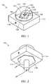
- FIG. 1is a perspective view of an LED apparatus in accordance with a first embodiment of the invention
- FIG. 2is another perspective view of the LED apparatus shown in FIG. 1 ;
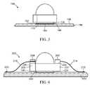
- FIG. 3is a cross sectional view of the LED apparatus of FIG. 1 mounted on a heat sink taken along line 3 - 3 ;
- FIG. 4is a cross sectional view of an LED apparatus in accordance with a second embodiment of the invention.
- FIG. 5is a cross sectional view of an LED apparatus in accordance with a third embodiment of the invention.
- FIG. 6is a cross sectional view of an LED apparatus in accordance with a fourth embodiment of the invention.
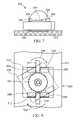
- FIG. 7is another cross sectional view of the LED apparatus shown in FIG. 6 taken in a direction orthogonal to the cross sectional view of FIG. 6 ;
- FIG. 8is a plan view of the LED apparatus shown in FIG. 6 and FIG. 7 ;
- FIG. 9is a perspective view of an LED apparatus in accordance with a fifth embodiment of the invention.
- FIG. 10is a cross sectional view of the LED apparatus shown in FIG. 9 ;
- FIG. 11is a cross sectional view of an LED apparatus in accordance with a sixth embodiment of the invention.
- FIG. 12is a cross sectional view of an LED apparatus in accordance with a seventh embodiment of the invention.
- FIG. 13is a perspective view of an LED apparatus in accordance with a eighth embodiment of the invention.
- FIG. 14is a cross sectional view of the LED apparatus shown in FIG. 13 mounted on a heat sink;
- FIG. 15is a perspective view of an LED apparatus in accordance with a ninth embodiment of the invention.
- FIG. 16is a perspective view of a second area of the LED apparatus shown in FIG. 15 ;
- FIGS. 17-19are a series of cross sectional views illustrating a process for welding the LED shown in FIG. 15 and FIG. 16 to a heat sink.
- the LED 100includes a sub-mount 102 and at least one LED die 104 mounted on the sub-mount.
- the sub-mount 102may comprise ceramic or silicon material, for example.
- the LED 100also includes a thermally conductive slug 106 having first and second areas 108 and 110 .
- the first area 108is thermally coupled to the sub-mount 102 .
- the slug 106also includes a post 112 protruding outwardly from the second area 110 .
- the post 112is operably configured to be received in an opening in a heat sink (not shown in FIG.
- the heat sinkmay be a metal or alloy plate or fixture to which the LED 100 is to be mounted, for example.
- the post 112 and slug 106may be formed together as a unitary body of thermally conductive material, such as aluminum or copper, for example.
- the LED 100also includes a molded body 114 and a lens 116 for coupling and/or directing light generated by the LED die 102 .
- the molded body 114surrounds the slug 106 and provides mounting features for the lens 116 .
- the sub-mount 102also includes one or more sub-mount electrodes (not shown) which are electrically coupled to the LED die 104 .
- the LED 100also includes a first terminal 118 for receiving a current supply conductor.
- the first terminal 118may be a press-fit terminal that receives and secures a conductor wire, for example.
- the first terminal 118is electrically coupled to a first pad 120 and the LED 100 further includes first connector 121 for connecting the between the first pad 120 and the sub-mount 102 to supply operating current to a first electrode on the sub-mount.
- the LED 100also includes a second pad 122 , a second wire bond connector 124 , and a second terminal (shown at 154 in FIG. 3 ) for supplying operating current to a second electrode on the sub-mount.
- the LED die 104may be coupled to the slug 106 and the slug may act as the second current supply terminal for the LED 100 .
- LEDsrequire electrical current to operate, which is generally supplied through conductors connected to positive and negative terminals of the LED or the LED package.
- some LED'smay be electrically configured such that either terminal can interchangeably function as positive or negative terminals, as is typical for conventional alternating current lighting components.
- the lens 116comprises an optically transparent material such as silicone gel having an outer surface 117 and extending between the sub-mount 102 and an outer surface 117 of the lens.
- the lens 116may comprise a rigid lens material that encloses the sub-mount 102 , with an optional filler material occupying a void between the outer surface 117 of the lens 116 and the sub-mount 102 .
- the LED 100is mounted on a metal heat sink 140 having a front surface 144 with a cylindrical opening 142 therein.
- the opening 142extends between a front surface 144 and a back surface 145 of the plate, and is dimensioned to receive the post 112 .
- the post 112includes a distal portion 148 that protrudes through the opening 142 when the LED 100 is mounted on the plate.
- a spring clip 150is placed on the distal portion 148 of the post 112 .
- the spring clip 150has at least one portion 152 (two portions 152 are shown in FIG. 3 ) that is operable to engage the back surface 145 of the heat sink to urge the second area 110 into thermal coupling with the front surface 144 of the heat sink 140 .
- the mounted LED 100also has a thermally conductive material 146 disposed between the front surface 144 of the heat sink 140 and the second area 110 of the slug 106 .
- Suitable thermally conductive materialsinclude thermally conductive adhesive tape, phase change materials, thermally conductive elastomer pads, and graphite plate, for example.
- the thermally conductive materialfills micro-voids and/or gaps between the front surface 144 and the second area 110 of the slug 106 that occur due to non-ideal surface finish and result in increased thermal resistance between the slug 106 and the heat sink 140 .
- the spring clip 150may be integrally attached to the distal portion 148 of the post 112 , and the portions 152 may be fabricated from sufficiently thin material (for example beryllium copper strips) to permit the spring clip portions to be compressed flush against the post 112 , while the post is being inserted through the opening 142 in the heat sink 140 .
- the thermally conductive material 146should be sufficiently compliant to permit the spring clip portions 152 to clear the opening 142 and to spring outwardly to the position as shown while the LED 100 is being depressed against the front surface 144 of the heat sink.
- An example of a suitably compressible thermally conductive materialis the Hyper Soft Thermally Conductive interface pad 5502 S available from Sumiitomo 3M Limited Tape and Adhesive Division of Tokoyo, Japan.
- electrical connectionsmay be easily made to the LED 100 by inserting a first current supply conductor 158 into the first terminal 118 , and a second current supply conductor 156 into the second terminal 154 .
- the first and second terminals 118 and 154are connected to the sub-mount 102 for supplying operating current to the LED die 104 .
- the post 112 and corresponding opening 142facilitate tool-free mounting of the LED 100 to the heat sink 140 in mechanical alignment with the heat sink.
- the size of the spring clip 150 and postshould be minimized so as to increase the thermal transfer area between the slug 106 and the heat sink 140 .
- a recess(not shown) having a shape generally corresponding to the slug 106 may be formed in the heat sink 140 to facilitate alignment between the heat sink and the LED 100 .
- the LED 100is operable to couple light into an optical distribution systems (not shown) having lenses, reflectors, and/or scattering surfaces, it may be desirable to precisely align the LED with respect to the optical distribution system. Such alignment may be facilitated by providing a recess for receiving and locating the slug 106 of the LED 100 .
- an LED 160includes a post 162 having a threaded portion 164 .
- the LED 160is generally similar to the LED 100 shown in FIGS. 1 and 2 and includes the slug 106 , first area 108 and the second area 110 .
- the LED 160is mounted on a metal heat sink 166 having a corresponding threaded opening 168 .
- the threaded opening 168may extend through the heat sink 166 from a front surface 170 to a back surface 172 of the heat sink 166 .
- the threaded opening 168may be a blind opening in the heat sink 166 .
- the mounted LED 160also has a thermally conductive material 174 disposed between the front surface 170 of the heat sink 166 and the second area 110 of the slug 106 .
- the LED 160is screwed into the threaded opening 168 and tightened to cause the thermally conductive material to generally conform to the front surface 170 and the second area 110 of the slug, thus providing a good thermal coupling therebetween.
- Improved thermal couplingmay be achieved by selecting a minimum diameter for the post 162 , which is still operable to provide sufficient securing force thus maximizing the size of the second area in thermal coupling with the heat sink 166 .
- the thickness of the heat sink 166may be selected to allow engagement of a sufficient length of the threaded portion 164 of the post 162 in the threaded opening 168 for reliably securing the LED 160 to the heat sink (for example, twice the diameter of the post). In general, when the LED 160 is secured to the heat sink 166 with a torque sufficient to cause an optimal compression of the thermally conductive material, a thermal resistance between the first area 110 and the heat sink 166 is also minimized.
- the molded body 114may be shaped for engagement by a tool, such as a wrench to facilitate tightening the LED 160 to a desired torque for optimal thermal transfer.
- an LED 190in another embodiment includes a thermally conductive material 192 bonded to the second area 110 of the slug 106 .
- the LED 190is generally similar to the LED 100 shown in FIGS. 1 and 2 except that in this embodiment there is no protruding post on the second area 110 .
- the thermally conductive material 192includes an outer surface 194 having adhesive properties.
- the LED 190may be supplied with thermally conductive material already bonded to the second area 110 of the slug 106 with the outer surface 194 being protected by the removable protective film.
- the protective filmis removed and the LED 190 is aligned to a heat sink 196 and pressured into contact with a first surface 198 of the heat sink.
- the heat sink 198includes a recess 199 having a shape that corresponds to the second area 110 of the LED 190 .
- the recess 199receives the second area 110 having the thermally conductive material 192 thereon, and facilitates alignment of the LED to the heat sink 196 .
- the thermally conductive materialincludes a thermally conductive material layer (not shown), with first and second adhesive layers on the inner and outer surfaces of the thermally conductive material layer.
- Suitable thermally conductive adhesive tapesare available from 3M Electronic Adhesives and Specialties Department of St. Paul, Minn.
- the 3M thermally conductive adhesive tapeshave ceramic fillers and pressure sensitive adhesive surfaces having a removable protective film of silicone treated polyester disposed on the adhesive surfaces.
- good adhesionmay be achieved by maintaining a pressure of about 5-50 psi for about 2-5 seconds.
- the LED 190 shown in FIG. 5facilitates quick retrofit of many existing LED products, with the only specific requirement for the heat sink 196 being provision of a reasonably clean flat surface for bonding.
- the LED 190may be securely bonded to the heat sink 196 without the need to allow for cure time, such as would be the case when using thermal conductive epoxies, for example.
- the bondmay be permanent or semi-permanent, depending on the adhesive used to bond the thermally conductive material 192 to the second area 110 and the heat sink 196 .
- removal of the LED 190may be aided by applying heat to de-laminate the tape, which must be replaced, should it be desired to reattach the LED to the heat sink 196 .
- an LED 200in another embodiment includes a molded body 206 having a first lug 202 and a second lug 204 located on opposite sides of an upper surface 208 of the body.
- the first and second lugs 202 and 204may be molded as part of the body 206 .
- the lugsmay be formed as part of the slug 106 .
- the LED 200also includes terminals 207 and 209 for receiving a current supply conductor.
- the terminals 207 and 209may be a press-fit terminal that receives and secures a conductor wire, as described above in connection with FIG. 1 .
- the LED 200is mounted on a heat sink 212 , which has a first spring clip 214 and a second spring clip 216 attached to the heat sink.
- the spring clips 214 and 216may be welded to the heat sink 212 at attachment points 218 and 220 respectively.
- the spring clips 214 and 216are leaf springs, and may be fabricated from beryllium copper or stainless steel, for example. In other embodiments the springs 214 and 216 may be formed as part of the heat sink 212 .
- each lug 202 and 204includes a slot 210 for receiving a free end of the respective spring clips 214 and 216 to cause the LED 200 to be pressured into contact with the heat sink 212 .
- the heat sink 212includes a recessed area 222 , for receiving the LED 200 .
- the recessed area 222has a shape and size corresponding to the slug 106 and provides an alignment guide for locating the LED 200 on the heat sink 212 .
- the recessed areaalso accommodates a thermally conductive material 224 .
- the lugs 202 and 204each include respective upwardly inclined ramp portions 226 and 228 .
- the ramp portions 226 and 228are oriented to receive respective free ends of the spring clips 214 and 216 in the position 230 shown in broken outline.
- the LED 200is then twisted in the direction of the arrows 234 and 236 to guide the free ends along the respective ramp portions 226 and 228 such that respective free ends of the spring clips 214 and 216 snap into engagement with the respective slots 210 in a position 232 .
- the free ends of the spring clips 214 and 216apply a downward pressure and also prevent the LED 200 from rotating further, thus securing the LED to the heat sink 212 .
- the lugs 202 and 204 and the ramps 226 and 228may be omitted, and the slots 210 may be formed directly in an upper surface of the body 206 or the slug 106 .
- the LED 200thus securely mounts the LED on the heat sink 212 , while facilitating easy removal and replacement, should it be necessary to replace the LED.
- the LED 200may be replaced by relatively unskilled and untrained personnel in the field, thus avoiding replacement of an entire fixture that carries the LED.
- an LED 240includes a thermally conductive slug 242 for mounting a one or more LED die 244 .
- four LED die 244are shown mounted on a thermally conductive sub-mount 246 , which is bonded to the slug 242 .
- the sub-mount 246may comprise silicon or a ceramic material, for example.
- the sub-mount 246further includes pads (not shown) for connecting a current supply conductor to the LED die 244 .
- the slug 242includes a mounting portion 248 for mounting the sub-mount 246 , and a post 250 .
- the post 250includes a threaded portion 252 at a distal end of the post.
- the LED 240includes a threaded nut 254 received on the threaded portion 252 of the post 250 .
- the slug 242is formed from a thermally conductive material such as aluminum, steel, or copper, for example.
- the slug 242comprises steel bolt having a surface coating of copper.
- the steel boltis stronger than a copper or aluminum slug and generally has a lower cost.
- Steelalso has a lower coefficient of thermal expansion (about 11 parts per million/° C.) than copper or aluminum (17 and 23 parts per million/° C. respectively).
- Materials used for mounting the LED die 244generally have a low thermal coefficient of expansion (Silicon has a thermal expansion coefficient of about 3.2 ppm/° C.). Steel thus provides a lower expansion coefficient mismatch between the slug 242 and the die 244 , thus reducing stress on the LED 240 due to temperature changes.
- the LED 240also includes first and second channels 256 and 258 which extend through the mounting portion 248 and the post of the slug 242 .
- the channels 256 and 258are operable to receive respective conductors 260 and 262 for supplying current to the LED die 244 .
- the conductors 260 and 262include respective bent over end portions 264 and 266 , which are soldered or ultrasonically bonded to the pads on the LED die 244 for providing electrical connection to the die through the sub-mount 246 .
- the conductors 260 and 262should be electrically isolated from the first and second channels 256 and 258 .
- the LED 240is shown mounted to a heat sink 270 .
- the heat sink 270includes an opening 272 for receiving the post 250 .
- a thermally conductive material 249is disposed between a front surface 274 of the heat sink 270 and the mounting portion 248 of the slug 242 .
- the LED 240is secured to the heat sink 270 by engaging and tightening the threaded nut 254 , thus causing the mounting portion 248 of the slug 242 to be urged into thermal coupling with the front surface 274 of the heat sink 270 .
- the conductors 260 and 262extend past the end of the threaded portion 252 of the post 250 , and facilitate connection to a current supply for supplying operating current to the LED 240 .
- the heat sink 270has a cylindrical can-shaped body, which further acts as a light reflector and/or light guide for collecting and directing the light generated by the LED die 244 .
- the conductors 260 and 262may be connected to a lighting fixture (not shown) on the ceiling of a room for suspending the LED apparatus.
- the heat sink 270may be a plate, or a heat sink having cooling fins, for example.
- a LED 300is shown mounted to an alternative heat sink 302 .
- the LED 300is generally similar to the LED 240 shown in FIG. 9 , having a post 304 with a threaded portion 306 , but having a cylindrical body 308 .
- the heat sink 302includes a cylindrical recess 312 and a threaded opening 314 for receiving the threaded portion 306 of the post 304 for securing the LED 300 .
- a thermally conductive material 318is disposed between the body 308 and a surface 320 of the recess 312 .
- the LED 300may be screwed into the threaded opening 314 and tightened to cause the thermally conductive material 318 to be compressed to provide thermal coupling between the body 308 and the heat sink 302 .
- an LED 340in another embodiment includes a cylindrical body 342 for mounting one or more LED die 344 .
- the LED 340includes conductors 346 and 348 which are connected to the LED die 344 as described above in connection with FIG. 9 .
- the LED 340is mounted on a heat sink 350 having a feed-through opening 354 for the conductors 346 and 348 .
- the heat sink 350also includes a connector block 356 , which is secured to the heat sink and includes connection sockets 358 and 360 for receiving the respective conductors 346 and 348 .
- the sockets 358 and 360are respectively connected to current supply conductors 362 and 364 for supplying current to the LED 340 .
- the sockets 358 and 360are generally similar to sockets used on printed circuit board assemblies for removably connecting electronic components to the board, and function to provide connection to the conductors 346 and 348 while simultaneously securing the LED 340 to the heat sink.
- the sockets 358 and 360are configured to provide sufficient force to at least partially compress a thermally conductive material 366 between the body 342 and a front surface 352 of the heat sink 350 , thus ensuring good thermal contact between the LED 340 and the heat sink.
- an LED 380includes a LED die 382 , mounted on a first surface 385 of a sub-mount 384 .
- the LED 380also includes first and second elongate conductor strips 386 and 388 bonded to the first surface 385 .
- the sub-mount 384comprises a metalized ceramic having connection pads (not shown) for soldering the conductor strips 386 and 388 in place. The connection pads may further be in electrical connection with the LED die 382 for supplying operating current thereto.
- the conductor stripseach have downwardly depending connector portions 390 and 392 respectively.
- the connector portions 390 and 392are folded over to extend downwardly from the first surface 385 of the sub-mount 384 .
- the LED 380is encapsulated in a plastic body 396 , which surrounds the sub-mount 384 (except for the LED die 382 and a back surface 398 of the sub-mount).
- the body 396also includes insertion snaps 402 molded into the body.
- the LED 380is mounted on a heat sink 404 having openings corresponding to the downwardly depending connector portions 390 and 392 , of which openings 410 and 412 are shown.
- the insertion snaps 402are received in the openings 410 and 412 , and the body 396 is pressed downwardly until the insertion snaps 402 engage a back surface 408 of the heat sink 404 .
- a thermally conductive material 414is disposed between the back surface 398 of the sub-mount 384 and a front surface 406 of the heat sink 404 , and under these conditions the back surface of the sub-mount is thermally coupled to the heat sink and secured in place.
- the thermally conductive material 414may be a compliant material, such as the 3M hypersoft thermal pads, described above in connection with FIG. 5 .
- the downwardly depending connector portions 390 and 392each have a “V” shaped cutout 416 and 418 for receiving insulated conductors 420 and 422 respectively.
- the cutouts 416 and 418also have circular portions 417 and 419 removed to permit ends of the connector portions to flex in the plane of the conductor portions.
- the insulated conductorseach include a conductive core 424 and an insulation layer 426 , and when the insulated conductors 420 and 422 are forced into the “V” shaped cutouts 416 and 418 , the respective cutouts flex to engage the conductor by displacing the insulation to electrically contact the conductive core.
- the plastic body 396prevents electrical shorting of the supplied current by insulating the leads from the heat sink 404 .
- an optical elementmay be provided in any of the alternative embodiments described above.
- the optical elementmay comprise a lens (not shown), which is pre-molded onto the sub-mount prior to attaching the conductive strips 386 and 388 .
- an LED 450in another embodiment includes a sub-mount 452 and at least one or more LED die 454 on the sub-mount.
- the LED 450also includes a metallic slug 456 having first and second areas 458 and 460 .
- the first area 458is thermally coupled to the sub-mount 452 .
- the slug 456also includes a metallic stud 462 protruding from the second area 460 .
- the LED 450includes a lens 464 for coupling and/or directing light generated by the LED die 454 .
- the lens 464is mounted in a molded body 468 , which together with the lens surrounds and protects the LED die 454 .
- the LED 450also includes terminals 470 and 472 and respective connectors 474 and 476 for supplying operating current to the LED die 454 .
- the connectors 474 and 476are insulation displacement type connectors, such as described above in connection with FIG. 13 and FIG. 14 .
- press fit terminalssuch as the terminal 118 in FIG. 1 may be provided.
- a process for mounting of the LED 450is described with reference to FIG. 17-FIG . 19 .
- the LED 450is received in a chuck 490 of a weld tool (not shown).
- the weld toolmay be part of a capacitive discharge stud welding system such as the Nelson® CD Lite I system, available from Nelson Stud Welding of Elyria, Ohio.
- the Nelson systemincludes a power supply unit for charging a 66,000 ⁇ F capacitor to a voltage in the range of 50V-220V.
- the weld toolis configured to receive various chuck attachments for receiving a work-piece to be welded.
- the weld toolincludes a cable for coupling to the capacitor, and further includes a switch for activating discharge of the capacitor through the chuck to the work-piece.
- the chuck 490includes an outer sleeve 492 having insulated portions 494 for engaging a heat sink 496 .
- the chuck 490further includes a holder 498 for holding the LED 450 and for conducting the weld current from the charged capacitor to the metallic slug 456 .
- the holder 498is received in the sleeve 492 and is moveable in a direction indicated by the arrow 500 with respect top the sleeve.
- the chuck 490also includes a spring 502 for urging the LED 450 toward the heat sink 496 .
- capacitive discharge stud welding systemsfacilitate adjustment of the urging force provided by the spring 502 to achieve a desired weld characteristic.
- the LED 450Prior to welding, the LED 450 is positioned such that the connectors 474 and 476 engage respective conductors 504 and 506 .
- the chuck 490is then placed over the LED 450 and the LED is initially positioned by the chuck 490 such that the stud 462 is proximate, but not in electrical contact with the heat sink 496 .
- the LED 450may be loaded into the chuck 490 and then positioned with respect to the heat sink while being held in the chuck.
- the power supplyis also activated to charge the capacitor to a desired voltage.
- the weld tool switchis activated by the user, which causes the capacitor to discharge through the holder 498 .
- An initial current flowis concentrated through the stud 462 and establishes an arc between the stud and the heat sink 496 (which is usually held at a ground potential).
- the concentrated current flowresults in a high current density through the stud 362 causing rapid heating of the stud, to an extent where the stud at least partially melts and/or vaporizes, thus permitting the second area 460 to move closer to the heat sink 496 .
- a plurality of arcs 510are established between the second area and the heat sink.
- the arcs 510cause local melting of the slug 456 in the second area 460 , and of the heat sink 496 , which securely welds the LED 450 to the heat sink when the second area is subsequently brought into contact with the heat sink.
- the resulting weld between the slug 456 of the LED 450 and the heat sink 496ensures a good thermal contact when the melted metal subsequently cools and solidifies.
- the capacitive discharge stud welding systemcouples a large current through the stud 362 in a very short timeframe (for example, 9000 A over 4 miliseconds).
- the resulting heating of the stud 462 and the surrounding second area 460is very rapid and heat dissipation is therefore minimized, thus localizing any damage or discoloration to the slug 456 and/or the heat sink 496 .
- the stud 462may be positioned in electrical contact with the heat sink 496 . Subsequently, when the switch is activated the welding current is coupled directly through the stud 462 to the heat sink 496 .
- Contact capacitive discharge stud weldingresults in slightly longer weld times than embodiments in which the discharge is initiated when there is a gap between the stud 462 and the heat sink 496 .
- the stud 462initializes the weld current in a desired location (i.e. at the center of the second area 460 ).
- the stud 462may be omitted.
- the initial weld currentestablishes an arc between the second area 460 and the heat sink 496 and may require more careful alignment of the LED 450 with respect to the heat sink to ensure that the resulting weld is sufficiently uniform.
- the LED's of the embodiments described hereinprovide for attachment to a heat sink without the use of solder, while providing good thermal coupling between the LED and the heat sink such that heat can be effectively transferred to the heat sink.
- Several of the embodiments described hereinfacilitate tool-free attachment to the heat sink, while other embodiments may be mounted using common hand tools or other convenient tools.
Landscapes
- Engineering & Computer Science (AREA)
- General Engineering & Computer Science (AREA)
- Physics & Mathematics (AREA)
- Microelectronics & Electronic Packaging (AREA)
- Optics & Photonics (AREA)
- Power Engineering (AREA)
- Arrangement Of Elements, Cooling, Sealing, Or The Like Of Lighting Devices (AREA)
- Led Device Packages (AREA)
- Fastening Of Light Sources Or Lamp Holders (AREA)
- Non-Portable Lighting Devices Or Systems Thereof (AREA)
- Cooling Or The Like Of Semiconductors Or Solid State Devices (AREA)
Abstract
Description
Claims (33)
Priority Applications (10)
| Application Number | Priority Date | Filing Date | Title |
|---|---|---|---|
| US11/956,270US7625104B2 (en) | 2007-12-13 | 2007-12-13 | Light emitting diode for mounting to a heat sink |
| TW097148331ATWI482927B (en) | 2007-12-13 | 2008-12-11 | Light emitting diode for mounting to a heat sink |
| CN201210439858.9ACN102943966B (en) | 2007-12-13 | 2008-12-11 | Light emitting diode disposed on heat dissipating device |
| PCT/IB2008/055230WO2009074964A2 (en) | 2007-12-13 | 2008-12-11 | Light emitting diode for mounting to a heat sink |
| KR1020167011509AKR101795526B1 (en) | 2007-12-13 | 2008-12-11 | Light emitting diode for mounting to a heat sink |
| JP2010537584AJP2011519148A (en) | 2007-12-13 | 2008-12-11 | Light emitting diode attached to heat sink |
| RU2010128901/07ARU2484363C2 (en) | 2007-12-13 | 2008-12-11 | Light emitting diode for installation on heat sink |
| CN2008801209197ACN101896760B (en) | 2007-12-13 | 2008-12-11 | Light emitting diode for mounting to a heat sink |
| KR1020107015404AKR101692336B1 (en) | 2007-12-13 | 2008-12-11 | Light emitting diode for mounting to a heat sink |
| EP08860796.5AEP2229553B1 (en) | 2007-12-13 | 2008-12-11 | Light emitting diode apparatus with a heat sink |
Applications Claiming Priority (1)
| Application Number | Priority Date | Filing Date | Title |
|---|---|---|---|
| US11/956,270US7625104B2 (en) | 2007-12-13 | 2007-12-13 | Light emitting diode for mounting to a heat sink |
Publications (2)
| Publication Number | Publication Date |
|---|---|
| US20090154166A1 US20090154166A1 (en) | 2009-06-18 |
| US7625104B2true US7625104B2 (en) | 2009-12-01 |
Family
ID=40752977
Family Applications (1)
| Application Number | Title | Priority Date | Filing Date |
|---|---|---|---|
| US11/956,270Active2028-08-07US7625104B2 (en) | 2007-12-13 | 2007-12-13 | Light emitting diode for mounting to a heat sink |
Country Status (7)
| Country | Link |
|---|---|
| US (1) | US7625104B2 (en) |
| EP (1) | EP2229553B1 (en) |
| KR (2) | KR101795526B1 (en) |
| CN (1) | CN101896760B (en) |
| RU (1) | RU2484363C2 (en) |
| TW (1) | TWI482927B (en) |
| WO (1) | WO2009074964A2 (en) |
Cited By (38)
| Publication number | Priority date | Publication date | Assignee | Title |
|---|---|---|---|---|
| US20080170400A1 (en)* | 2007-01-11 | 2008-07-17 | Sony Corporation | Backlight unit and display device |
| US20090129076A1 (en)* | 2007-11-19 | 2009-05-21 | Osram Gesellschaft Mit Beschrankter Haftung | Illumination device comprising a heat sink |
| US20090154180A1 (en)* | 2007-12-18 | 2009-06-18 | Sl Seobong | Heat-dissipating apparatus |
| US20090267086A1 (en)* | 2008-04-29 | 2009-10-29 | Wei Shi | Thermal Management For LED |
| US20100025718A1 (en)* | 2008-07-31 | 2010-02-04 | Wei Shi | Top contact LED thermal management |
| US20100060157A1 (en)* | 2008-09-10 | 2010-03-11 | Wei Shi | Phosphor layer arrangement for use with light emitting diodes |
| US20100110671A1 (en)* | 2008-05-16 | 2010-05-06 | Musco Corporation | Method, system, and apparatus for highly controlled light distribution from light fixture using multiple light sources (leds) |
| US20100172124A1 (en)* | 2009-01-07 | 2010-07-08 | Cho Joo-Woan | Light source, light-emitting module having the same and backlight unit having the same |
| US20100219735A1 (en)* | 2009-02-27 | 2010-09-02 | Toshiba Lighting & Technology Corporation | Lighting device and lighting fixture |
| US20100225216A1 (en)* | 2009-03-09 | 2010-09-09 | Han-Ming Lee | Switch complementary equal brightness LED lamp |
| US20100237363A1 (en)* | 2009-03-19 | 2010-09-23 | Christy Alexander C | Apparatus for Dissipating Thermal Energy Generated by Current Flow in Semiconductor Circuits |
| US20100243230A1 (en)* | 2009-03-25 | 2010-09-30 | Wah Hong Industrial Corp. | Heat-dissipating device including a plating metal layer |
| US20100315813A1 (en)* | 2007-07-12 | 2010-12-16 | Sunovia Energy Technologies, Inc. | Solid state light unit and heat sink, and method for thermal management of a solid state light unit |
| US20100314655A1 (en)* | 2009-03-02 | 2010-12-16 | Thompson Joseph B | Light Emitting Assemblies and Portions Thereof |
| US20110063842A1 (en)* | 2009-09-14 | 2011-03-17 | Toshiba Lighting & Technology Corporation | Light-emitting device and illumination device |
| US20110214851A1 (en)* | 2009-08-14 | 2011-09-08 | Wah Hong Industrial Corp. | Use of a graphite heat-dissipation device including a plating metal layer |
| WO2011137355A1 (en)* | 2010-04-30 | 2011-11-03 | Uniflux Led, Inc. | A cooling structure for led lamps |
| US20120075871A1 (en)* | 2010-09-27 | 2012-03-29 | Au Optronics Corporation | Assemblage structure for OLED lighting modules |
| WO2012064901A1 (en)* | 2010-11-11 | 2012-05-18 | Bridgelux, Inc. | Driver-free light-emiting device |
| US8272763B1 (en) | 2009-10-02 | 2012-09-25 | Genesis LED Solutions | LED luminaire |
| US8308320B2 (en) | 2009-11-12 | 2012-11-13 | Cooper Technologies Company | Light emitting diode modules with male/female features for end-to-end coupling |
| US20120306343A1 (en)* | 2010-02-08 | 2012-12-06 | Cheng-Kuang Wu | Light device |
| US8354783B2 (en) | 2009-09-24 | 2013-01-15 | Toshiba Lighting & Technology Corporation | Light-emitting device.having a frame member surrounding light-emitting elements and illumination device utilizing light-emitting device |
| US8382325B2 (en) | 2009-06-30 | 2013-02-26 | Toshiba Lighting & Technology Corporation | Lamp and lighting equipment using the same |
| US8391009B2 (en) | 2010-06-18 | 2013-03-05 | Sunonwealth Electric Machine Industry Co., Ltd. | Heat dissipating assembly |
| US8415889B2 (en) | 2009-07-29 | 2013-04-09 | Toshiba Lighting & Technology Corporation | LED lighting equipment |
| US8500316B2 (en) | 2010-02-26 | 2013-08-06 | Toshiba Lighting & Technology Corporation | Self-ballasted lamp and lighting equipment |
| US8506126B2 (en) | 2010-05-12 | 2013-08-13 | Sq Technologies Inc. | Retrofit LED lamp assembly for sealed optical lamps |
| US8616720B2 (en) | 2010-04-27 | 2013-12-31 | Cooper Technologies Company | Linkable linear light emitting diode system |
| US8622569B1 (en) | 2009-07-17 | 2014-01-07 | Musco Corporation | Method, system and apparatus for controlling light distribution using swivel-mount led light sources |
| DE102012211143A1 (en)* | 2012-06-28 | 2014-01-23 | Osram Gmbh | Carrier e.g. circuit board, for e.g. organic LED of headlight for automobile, has guidance bodies linked with components at front side and exposed with respect to carrier at rear side, where bodies are projected over carrier at rear side |
| US8678618B2 (en) | 2009-09-25 | 2014-03-25 | Toshiba Lighting & Technology Corporation | Self-ballasted lamp having a light-transmissive member in contact with light emitting elements and lighting equipment incorporating the same |
| US8764220B2 (en) | 2010-04-28 | 2014-07-01 | Cooper Technologies Company | Linear LED light module |
| US8992047B2 (en) | 2008-05-16 | 2015-03-31 | Musco Corporation | Apparatus, method, and system for highly controlled light distribution using multiple light sources |
| WO2015155647A1 (en) | 2014-04-07 | 2015-10-15 | Koninklijke Philips N.V. | Lighting device including a thermally conductive body and a semiconductor light emitting device |
| US9543475B2 (en)* | 2014-11-14 | 2017-01-10 | Samsung Electronics Co., Ltd | Light emitting device and method of manufacturing the same |
| US20170261195A1 (en)* | 2016-03-10 | 2017-09-14 | H4X E.U. | Lamp |
| US10403792B2 (en)* | 2016-03-07 | 2019-09-03 | Rayvio Corporation | Package for ultraviolet emitting devices |
Families Citing this family (57)
| Publication number | Priority date | Publication date | Assignee | Title |
|---|---|---|---|---|
| CN101836042B (en)* | 2007-09-21 | 2014-11-05 | 库帕技术公司 | Light emitting diode recessed light fixture |
| US7866850B2 (en)* | 2008-02-26 | 2011-01-11 | Journée Lighting, Inc. | Light fixture assembly and LED assembly |
| USD633649S1 (en) | 2008-03-31 | 2011-03-01 | Cooper Technologies Company | LED light fixture |
| US8492179B2 (en)* | 2008-07-11 | 2013-07-23 | Koninklijke Philips N.V. | Method of mounting a LED module to a heat sink |
| CN102187149B (en)* | 2008-10-14 | 2014-11-05 | 皇家飞利浦电子股份有限公司 | A system for heat conduction between two connectable members |
| CN101740678A (en)* | 2008-11-10 | 2010-06-16 | 富士迈半导体精密工业(上海)有限公司 | Solid state light-emitting element and light source module |
| US8152336B2 (en) | 2008-11-21 | 2012-04-10 | Journée Lighting, Inc. | Removable LED light module for use in a light fixture assembly |
| US8791499B1 (en) | 2009-05-27 | 2014-07-29 | Soraa, Inc. | GaN containing optical devices and method with ESD stability |
| US8596837B1 (en) | 2009-07-21 | 2013-12-03 | Cooper Technologies Company | Systems, methods, and devices providing a quick-release mechanism for a modular LED light engine |
| CA2768777C (en) | 2009-07-21 | 2017-11-28 | Cooper Technologies Company | Interfacing a light emitting diode (led) module to a heat sink assembly, a light reflector and electrical circuits |
| WO2011019945A1 (en)* | 2009-08-12 | 2011-02-17 | Journee Lighting, Inc. | Led light module for use in a lighting assembly |
| EP2327929A1 (en)* | 2009-11-25 | 2011-06-01 | Hella KGaA Hueck & Co. | Light unit for vehicles and mounting method |
| US9583690B2 (en)* | 2010-04-07 | 2017-02-28 | Shenzhen Qin Bo Core Technology Development Co., Ltd. | LED lampwick, LED chip, and method for manufacturing LED chip |
| US8803452B2 (en)* | 2010-10-08 | 2014-08-12 | Soraa, Inc. | High intensity light source |
| US9351348B2 (en) | 2010-10-27 | 2016-05-24 | Koninklijke Philips N.V. | Laminate support film for fabrication of light emitting devices and method of fabrication |
| CN102109116B (en)* | 2010-12-27 | 2016-06-22 | 秦彪 | Led light module and led chip |
| WO2012097721A1 (en)* | 2011-01-21 | 2012-07-26 | 贵州光浦森光电有限公司 | Method and device for constructing high-power led lighting fixture |
| US8829774B1 (en) | 2011-02-11 | 2014-09-09 | Soraa, Inc. | Illumination source with direct die placement |
| US8618742B2 (en)* | 2011-02-11 | 2013-12-31 | Soraa, Inc. | Illumination source and manufacturing methods |
| US10036544B1 (en) | 2011-02-11 | 2018-07-31 | Soraa, Inc. | Illumination source with reduced weight |
| US8643257B2 (en)* | 2011-02-11 | 2014-02-04 | Soraa, Inc. | Illumination source with reduced inner core size |
| WO2012131519A1 (en)* | 2011-03-25 | 2012-10-04 | Koninklijke Philips Electronics N.V. | Thermal interface pad material with perforated liner |
| USD694722S1 (en) | 2011-08-15 | 2013-12-03 | Soraa, Inc. | Heatsink |
| US9488324B2 (en) | 2011-09-02 | 2016-11-08 | Soraa, Inc. | Accessories for LED lamp systems |
| US9109760B2 (en) | 2011-09-02 | 2015-08-18 | Soraa, Inc. | Accessories for LED lamps |
| US8884517B1 (en) | 2011-10-17 | 2014-11-11 | Soraa, Inc. | Illumination sources with thermally-isolated electronics |
| ITBO20110630A1 (en)* | 2011-11-07 | 2013-05-08 | Schneider Electric Ind Italia S P A | SUPPORTING ELEMENT OPTIMIZED FOR POWER LED |
| US8985794B1 (en) | 2012-04-17 | 2015-03-24 | Soraa, Inc. | Providing remote blue phosphors in an LED lamp |
| US9360190B1 (en) | 2012-05-14 | 2016-06-07 | Soraa, Inc. | Compact lens for high intensity light source |
| US10436422B1 (en) | 2012-05-14 | 2019-10-08 | Soraa, Inc. | Multi-function active accessories for LED lamps |
| US9310052B1 (en) | 2012-09-28 | 2016-04-12 | Soraa, Inc. | Compact lens for high intensity light source |
| US9995439B1 (en) | 2012-05-14 | 2018-06-12 | Soraa, Inc. | Glare reduced compact lens for high intensity light source |
| US9215764B1 (en) | 2012-11-09 | 2015-12-15 | Soraa, Inc. | High-temperature ultra-low ripple multi-stage LED driver and LED control circuits |
| DE102012024459A1 (en) | 2012-12-14 | 2014-06-18 | Diehl Aerospace Gmbh | Arrangement of a heat sink and recorded thereon, heat generating electronic components |
| US9565782B2 (en) | 2013-02-15 | 2017-02-07 | Ecosense Lighting Inc. | Field replaceable power supply cartridge |
| US9267661B1 (en) | 2013-03-01 | 2016-02-23 | Soraa, Inc. | Apportioning optical projection paths in an LED lamp |
| US9435525B1 (en) | 2013-03-08 | 2016-09-06 | Soraa, Inc. | Multi-part heat exchanger for LED lamps |
| US9468365B2 (en)* | 2013-03-15 | 2016-10-18 | Sanovas, Inc. | Compact light source |
| US9737195B2 (en) | 2013-03-15 | 2017-08-22 | Sanovas, Inc. | Handheld resector balloon system |
| US10349977B2 (en) | 2013-03-15 | 2019-07-16 | Sanovas Intellectual Property, Llc | Resector balloon catheter with multi-port hub |
| CN103363357B (en)* | 2013-07-17 | 2015-12-09 | 晶科电子(广州)有限公司 | A kind of LED light source with great heat radiation effect |
| US10477636B1 (en) | 2014-10-28 | 2019-11-12 | Ecosense Lighting Inc. | Lighting systems having multiple light sources |
| US11306897B2 (en) | 2015-02-09 | 2022-04-19 | Ecosense Lighting Inc. | Lighting systems generating partially-collimated light emissions |
| US9869450B2 (en) | 2015-02-09 | 2018-01-16 | Ecosense Lighting Inc. | Lighting systems having a truncated parabolic- or hyperbolic-conical light reflector, or a total internal reflection lens; and having another light reflector |
| US9746159B1 (en) | 2015-03-03 | 2017-08-29 | Ecosense Lighting Inc. | Lighting system having a sealing system |
| US9568665B2 (en) | 2015-03-03 | 2017-02-14 | Ecosense Lighting Inc. | Lighting systems including lens modules for selectable light distribution |
| US9651216B2 (en) | 2015-03-03 | 2017-05-16 | Ecosense Lighting Inc. | Lighting systems including asymmetric lens modules for selectable light distribution |
| US9651227B2 (en) | 2015-03-03 | 2017-05-16 | Ecosense Lighting Inc. | Low-profile lighting system having pivotable lighting enclosure |
| US9857554B2 (en)* | 2015-03-18 | 2018-01-02 | Smart Vision Lights | Spring clips for mounting optics structures on an associated circuit board, and assemblies including the spring clips |
| USD785218S1 (en) | 2015-07-06 | 2017-04-25 | Ecosense Lighting Inc. | LED luminaire having a mounting system |
| USD782094S1 (en) | 2015-07-20 | 2017-03-21 | Ecosense Lighting Inc. | LED luminaire having a mounting system |
| USD782093S1 (en) | 2015-07-20 | 2017-03-21 | Ecosense Lighting Inc. | LED luminaire having a mounting system |
| US9651232B1 (en) | 2015-08-03 | 2017-05-16 | Ecosense Lighting Inc. | Lighting system having a mounting device |
| US10077896B2 (en) | 2015-09-14 | 2018-09-18 | Trent Neil Butcher | Lighting devices including at least one light-emitting device and systems including at least one lighting device |
| US9927113B2 (en) | 2016-05-26 | 2018-03-27 | Karl Storz Imaging, Inc. | Heat sink structure and LED heat sink assemblies |
| CN108540086A (en)* | 2018-01-18 | 2018-09-14 | 浙江人和光伏科技有限公司 | A kind of conductive module of solar battery connecting box |
| USD1035972S1 (en)* | 2023-10-12 | 2024-07-16 | Nanning Weiliqi E-commerce Co., Ltd. | Lamp |
Citations (6)
| Publication number | Priority date | Publication date | Assignee | Title |
|---|---|---|---|---|
| US6517218B2 (en) | 2000-03-31 | 2003-02-11 | Relume Corporation | LED integrated heat sink |
| US6582100B1 (en) | 2000-08-09 | 2003-06-24 | Relume Corporation | LED mounting system |
| US6911731B2 (en) | 2003-05-14 | 2005-06-28 | Jiahn-Chang Wu | Solderless connection in LED module |
| US20060138443A1 (en)* | 2004-12-23 | 2006-06-29 | Iii-N Technology, Inc. | Encapsulation and packaging of ultraviolet and deep-ultraviolet light emitting diodes |
| US20070120138A1 (en)* | 2005-11-28 | 2007-05-31 | Visteon Global Technologies, Inc. | Multi-layer light emitting device with integrated thermoelectric chip |
| US20070170448A1 (en)* | 2006-01-24 | 2007-07-26 | Sony Corporation | Semiconductor light emitting device and semiconductor light emitting device assembly |
Family Cites Families (16)
| Publication number | Priority date | Publication date | Assignee | Title |
|---|---|---|---|---|
| ATE47624T1 (en)* | 1984-11-15 | 1989-11-15 | Japan Traffic Manage Tech Ass | SIGNAL LIGHT UNIT WITH HEAT DISSIPATION. |
| US5890794A (en)* | 1996-04-03 | 1999-04-06 | Abtahi; Homayoon | Lighting units |
| JP2002223007A (en)* | 2000-11-22 | 2002-08-09 | Matsushita Electric Ind Co Ltd | Light source unit and semiconductor light emitting lighting device using the same |
| JP3965929B2 (en)* | 2001-04-02 | 2007-08-29 | 日亜化学工業株式会社 | LED lighting device |
| EP1467414A4 (en)* | 2001-12-29 | 2007-07-11 | Hangzhou Fuyang Xinying Dianzi | A led and led lamp |
| US7093958B2 (en)* | 2002-04-09 | 2006-08-22 | Osram Sylvania Inc. | LED light source assembly |
| US6715900B2 (en)* | 2002-05-17 | 2004-04-06 | A L Lightech, Inc. | Light source arrangement |
| US7170151B2 (en)* | 2003-01-16 | 2007-01-30 | Philips Lumileds Lighting Company, Llc | Accurate alignment of an LED assembly |
| TWI246370B (en)* | 2004-01-29 | 2005-12-21 | Radiant Opto Electronics Corp | Light-emitting diode module substrate having heat conduction effect |
| GB2413840B (en)* | 2004-05-07 | 2006-06-14 | Savage Marine Ltd | Underwater lighting |
| DE202004013773U1 (en)* | 2004-09-04 | 2004-11-11 | Zweibrüder Optoelectronics GmbH | lamp |
| EP1825524A4 (en)* | 2004-12-16 | 2010-06-16 | Seoul Semiconductor Co Ltd | CONNECTION GRID COMPRISING A THERMAL DISSIPATOR SUPPORT RING, METHOD FOR MANUFACTURING LIGHT-EMITTING DIODE HOUSING USING THE SAME, AND LIGHT-EMITTING DIODE HOUSING MADE THEREBY |
| KR101115800B1 (en)* | 2004-12-27 | 2012-03-08 | 엘지디스플레이 주식회사 | Light-emitting device package, method for fabricating the same and backlight unit |
| KR100665005B1 (en)* | 2004-12-30 | 2007-01-09 | 삼성전기주식회사 | Backlight device using light emitting diode |
| EP2023414A4 (en)* | 2006-05-31 | 2010-02-17 | Denki Kagaku Kogyo Kk | LED LIGHT SOURCE MODULE |
| RU64321U1 (en)* | 2007-02-14 | 2007-06-27 | Владимир Александрович Круглов | LIGHTING DEVICE |
- 2007
- 2007-12-13USUS11/956,270patent/US7625104B2/enactiveActive
- 2008
- 2008-12-11WOPCT/IB2008/055230patent/WO2009074964A2/enactiveApplication Filing
- 2008-12-11EPEP08860796.5Apatent/EP2229553B1/enactiveActive
- 2008-12-11KRKR1020167011509Apatent/KR101795526B1/enactiveActive
- 2008-12-11KRKR1020107015404Apatent/KR101692336B1/enactiveActive
- 2008-12-11RURU2010128901/07Apatent/RU2484363C2/enactive
- 2008-12-11CNCN2008801209197Apatent/CN101896760B/enactiveActive
- 2008-12-11TWTW097148331Apatent/TWI482927B/enactive
Patent Citations (6)
| Publication number | Priority date | Publication date | Assignee | Title |
|---|---|---|---|---|
| US6517218B2 (en) | 2000-03-31 | 2003-02-11 | Relume Corporation | LED integrated heat sink |
| US6582100B1 (en) | 2000-08-09 | 2003-06-24 | Relume Corporation | LED mounting system |
| US6911731B2 (en) | 2003-05-14 | 2005-06-28 | Jiahn-Chang Wu | Solderless connection in LED module |
| US20060138443A1 (en)* | 2004-12-23 | 2006-06-29 | Iii-N Technology, Inc. | Encapsulation and packaging of ultraviolet and deep-ultraviolet light emitting diodes |
| US20070120138A1 (en)* | 2005-11-28 | 2007-05-31 | Visteon Global Technologies, Inc. | Multi-layer light emitting device with integrated thermoelectric chip |
| US20070170448A1 (en)* | 2006-01-24 | 2007-07-26 | Sony Corporation | Semiconductor light emitting device and semiconductor light emitting device assembly |
Cited By (68)
| Publication number | Priority date | Publication date | Assignee | Title |
|---|---|---|---|---|
| US20080170400A1 (en)* | 2007-01-11 | 2008-07-17 | Sony Corporation | Backlight unit and display device |
| US8075150B2 (en)* | 2007-01-11 | 2011-12-13 | Sony Corporation | Backlight unit and display device |
| US8220977B2 (en)* | 2007-07-12 | 2012-07-17 | Sunovia Energy Technologies, Inc. | Solid state light unit and heat sink, and method for thermal management of a solid state light unit |
| US20100315813A1 (en)* | 2007-07-12 | 2010-12-16 | Sunovia Energy Technologies, Inc. | Solid state light unit and heat sink, and method for thermal management of a solid state light unit |
| US20090129076A1 (en)* | 2007-11-19 | 2009-05-21 | Osram Gesellschaft Mit Beschrankter Haftung | Illumination device comprising a heat sink |
| US8157418B2 (en)* | 2007-11-19 | 2012-04-17 | Osram Ag | Illumination device comprising a heat sink |
| US20090154180A1 (en)* | 2007-12-18 | 2009-06-18 | Sl Seobong | Heat-dissipating apparatus |
| US8201976B2 (en)* | 2007-12-18 | 2012-06-19 | Sl Seobong | Heat-dissipating apparatus |
| US20090267086A1 (en)* | 2008-04-29 | 2009-10-29 | Wei Shi | Thermal Management For LED |
| US20100136725A1 (en)* | 2008-04-29 | 2010-06-03 | Bridgelux, Inc. | Thermal management for led |
| US7888688B2 (en)* | 2008-04-29 | 2011-02-15 | Bridgelux, Inc. | Thermal management for LED |
| US7892870B2 (en)* | 2008-04-29 | 2011-02-22 | Bridgelux, Inc. | Thermal management for LED |
| US8602588B2 (en) | 2008-05-16 | 2013-12-10 | Musco Corporation | Method, system, and apparatus for highly controlled light distribution from light fixture using multiple light sources (LEDs) |
| US20100110671A1 (en)* | 2008-05-16 | 2010-05-06 | Musco Corporation | Method, system, and apparatus for highly controlled light distribution from light fixture using multiple light sources (leds) |
| US8992047B2 (en) | 2008-05-16 | 2015-03-31 | Musco Corporation | Apparatus, method, and system for highly controlled light distribution using multiple light sources |
| US20100025718A1 (en)* | 2008-07-31 | 2010-02-04 | Wei Shi | Top contact LED thermal management |
| US8080827B2 (en) | 2008-07-31 | 2011-12-20 | Bridgelux, Inc. | Top contact LED thermal management |
| US7859190B2 (en) | 2008-09-10 | 2010-12-28 | Bridgelux, Inc. | Phosphor layer arrangement for use with light emitting diodes |
| US20100060157A1 (en)* | 2008-09-10 | 2010-03-11 | Wei Shi | Phosphor layer arrangement for use with light emitting diodes |
| US20100172124A1 (en)* | 2009-01-07 | 2010-07-08 | Cho Joo-Woan | Light source, light-emitting module having the same and backlight unit having the same |
| US8684550B2 (en)* | 2009-01-07 | 2014-04-01 | Samsung Display Co., Ltd. | Light source, light-emitting module having the same and backlight unit have the same |
| US20100219735A1 (en)* | 2009-02-27 | 2010-09-02 | Toshiba Lighting & Technology Corporation | Lighting device and lighting fixture |
| US8760042B2 (en) | 2009-02-27 | 2014-06-24 | Toshiba Lighting & Technology Corporation | Lighting device having a through-hole and a groove portion formed in the thermally conductive main body |
| US20100314655A1 (en)* | 2009-03-02 | 2010-12-16 | Thompson Joseph B | Light Emitting Assemblies and Portions Thereof |
| US8269248B2 (en)* | 2009-03-02 | 2012-09-18 | Thompson Joseph B | Light emitting assemblies and portions thereof |
| US20100225216A1 (en)* | 2009-03-09 | 2010-09-09 | Han-Ming Lee | Switch complementary equal brightness LED lamp |
| US20100237363A1 (en)* | 2009-03-19 | 2010-09-23 | Christy Alexander C | Apparatus for Dissipating Thermal Energy Generated by Current Flow in Semiconductor Circuits |
| US8168990B2 (en)* | 2009-03-19 | 2012-05-01 | Cid Technologies Llc | Apparatus for dissipating thermal energy generated by current flow in semiconductor circuits |
| US20100237364A1 (en)* | 2009-03-19 | 2010-09-23 | Christy Alexander C | Thermal Energy Dissipating and Light Emitting Diode Mounting Arrangement |
| US20100252853A1 (en)* | 2009-03-19 | 2010-10-07 | Christy Alexander C | Thermal Energy Dissipating Arrangement for a Light Emitting Diode |
| US9097468B2 (en) | 2009-03-25 | 2015-08-04 | Wah Hong Industrial Corp. | Use of a graphite heat-dissipation device including a plating metal layer |
| US20100243230A1 (en)* | 2009-03-25 | 2010-09-30 | Wah Hong Industrial Corp. | Heat-dissipating device including a plating metal layer |
| US8382325B2 (en) | 2009-06-30 | 2013-02-26 | Toshiba Lighting & Technology Corporation | Lamp and lighting equipment using the same |
| US8622569B1 (en) | 2009-07-17 | 2014-01-07 | Musco Corporation | Method, system and apparatus for controlling light distribution using swivel-mount led light sources |
| US8415889B2 (en) | 2009-07-29 | 2013-04-09 | Toshiba Lighting & Technology Corporation | LED lighting equipment |
| US8955580B2 (en)* | 2009-08-14 | 2015-02-17 | Wah Hong Industrial Corp. | Use of a graphite heat-dissipation device including a plating metal layer |
| US20110214851A1 (en)* | 2009-08-14 | 2011-09-08 | Wah Hong Industrial Corp. | Use of a graphite heat-dissipation device including a plating metal layer |
| US8360606B2 (en)* | 2009-09-14 | 2013-01-29 | Toshiba Lighting & Technology Corporation | Light-emitting device and illumination device |
| US20110063842A1 (en)* | 2009-09-14 | 2011-03-17 | Toshiba Lighting & Technology Corporation | Light-emitting device and illumination device |
| US8354783B2 (en) | 2009-09-24 | 2013-01-15 | Toshiba Lighting & Technology Corporation | Light-emitting device.having a frame member surrounding light-emitting elements and illumination device utilizing light-emitting device |
| US8998457B2 (en) | 2009-09-25 | 2015-04-07 | Toshiba Lighting & Technology Corporation | Self-ballasted lamp and lighting equipment having a support portion in contact with an inner circumference of a base body |
| US8678618B2 (en) | 2009-09-25 | 2014-03-25 | Toshiba Lighting & Technology Corporation | Self-ballasted lamp having a light-transmissive member in contact with light emitting elements and lighting equipment incorporating the same |
| US8272763B1 (en) | 2009-10-02 | 2012-09-25 | Genesis LED Solutions | LED luminaire |
| US8308320B2 (en) | 2009-11-12 | 2012-11-13 | Cooper Technologies Company | Light emitting diode modules with male/female features for end-to-end coupling |
| US8632214B1 (en) | 2009-11-12 | 2014-01-21 | Cooper Technologies Company | Light modules with uninterrupted arrays of LEDs |
| US9518706B2 (en) | 2009-11-12 | 2016-12-13 | Cooper Technologies Company | Linear LED light module |
| US20120306343A1 (en)* | 2010-02-08 | 2012-12-06 | Cheng-Kuang Wu | Light device |
| US8500316B2 (en) | 2010-02-26 | 2013-08-06 | Toshiba Lighting & Technology Corporation | Self-ballasted lamp and lighting equipment |
| US10648652B2 (en) | 2010-04-27 | 2020-05-12 | Eaton Intelligent Power Limited | LED lighting system with distributive powering scheme |
| US10006592B2 (en) | 2010-04-27 | 2018-06-26 | Cooper Technologies Company | LED lighting system with distributive powering scheme |
| US8616720B2 (en) | 2010-04-27 | 2013-12-31 | Cooper Technologies Company | Linkable linear light emitting diode system |
| US9285085B2 (en) | 2010-04-27 | 2016-03-15 | Cooper Technologies Company | LED lighting system with distributive powering scheme |
| US8764220B2 (en) | 2010-04-28 | 2014-07-01 | Cooper Technologies Company | Linear LED light module |
| WO2011137355A1 (en)* | 2010-04-30 | 2011-11-03 | Uniflux Led, Inc. | A cooling structure for led lamps |
| US8506126B2 (en) | 2010-05-12 | 2013-08-13 | Sq Technologies Inc. | Retrofit LED lamp assembly for sealed optical lamps |
| US8391009B2 (en) | 2010-06-18 | 2013-03-05 | Sunonwealth Electric Machine Industry Co., Ltd. | Heat dissipating assembly |
| US20120075871A1 (en)* | 2010-09-27 | 2012-03-29 | Au Optronics Corporation | Assemblage structure for OLED lighting modules |
| US9046233B2 (en)* | 2010-09-27 | 2015-06-02 | Au Optronics Corporation | Assemblage structure for OLED lighting modules |
| US9091399B2 (en) | 2010-11-11 | 2015-07-28 | Bridgelux, Inc. | Driver-free light-emitting device |
| WO2012064901A1 (en)* | 2010-11-11 | 2012-05-18 | Bridgelux, Inc. | Driver-free light-emiting device |
| US10047914B2 (en) | 2010-11-11 | 2018-08-14 | Xenio Systems, Inc. | Driver-free light-emitting device |
| DE102012211143A1 (en)* | 2012-06-28 | 2014-01-23 | Osram Gmbh | Carrier e.g. circuit board, for e.g. organic LED of headlight for automobile, has guidance bodies linked with components at front side and exposed with respect to carrier at rear side, where bodies are projected over carrier at rear side |
| WO2015155647A1 (en) | 2014-04-07 | 2015-10-15 | Koninklijke Philips N.V. | Lighting device including a thermally conductive body and a semiconductor light emitting device |
| US10056361B2 (en) | 2014-04-07 | 2018-08-21 | Lumileds Llc | Lighting device including a thermally conductive body and a semiconductor light emitting device |
| US9543475B2 (en)* | 2014-11-14 | 2017-01-10 | Samsung Electronics Co., Ltd | Light emitting device and method of manufacturing the same |
| US10403792B2 (en)* | 2016-03-07 | 2019-09-03 | Rayvio Corporation | Package for ultraviolet emitting devices |
| US20170261195A1 (en)* | 2016-03-10 | 2017-09-14 | H4X E.U. | Lamp |
| US10480770B2 (en)* | 2016-03-10 | 2019-11-19 | H4X E.U. | Lamp |
Also Published As
| Publication number | Publication date |
|---|---|
| WO2009074964A3 (en) | 2009-09-03 |
| RU2484363C2 (en) | 2013-06-10 |
| CN101896760A (en) | 2010-11-24 |
| RU2010128901A (en) | 2012-01-20 |
| EP2229553B1 (en) | 2019-02-27 |
| KR101795526B1 (en) | 2017-11-10 |
| TWI482927B (en) | 2015-05-01 |
| CN101896760B (en) | 2012-12-26 |
| US20090154166A1 (en) | 2009-06-18 |
| TW200933080A (en) | 2009-08-01 |
| KR20160055957A (en) | 2016-05-18 |
| KR20100097733A (en) | 2010-09-03 |
| WO2009074964A2 (en) | 2009-06-18 |
| EP2229553A2 (en) | 2010-09-22 |
| KR101692336B1 (en) | 2017-01-04 |
Similar Documents
| Publication | Publication Date | Title |
|---|---|---|
| US7625104B2 (en) | Light emitting diode for mounting to a heat sink | |
| RU2464671C2 (en) | Solderless inbuilt connector of light diode assembly and heat sink for light diode | |
| CN102007830B (en) | Thermally conductive assembly elements for attaching printed circuit boards to heat sinks | |
| KR101398701B1 (en) | Led device, manufacturing method thereof, and light-emitting device | |
| US8079731B2 (en) | Lighting apparatus | |
| EP2527729B1 (en) | Illumination apparatus | |
| US8410512B2 (en) | Solid state light emitting apparatus with thermal management structures and methods of manufacturing | |
| CN105830544B (en) | LED substrate with electrical connections through bridges | |
| US20130265782A1 (en) | Heat-sink/connector system for light emitting diode | |
| JP4920824B2 (en) | Photoelectric element | |
| US20110069502A1 (en) | Mounting Fixture for LED Lighting Modules | |
| JPH0447962Y2 (en) | ||
| CN112874430B (en) | Device for connecting a light source to a power supply unit | |
| JP2011519148A (en) | Light emitting diode attached to heat sink | |
| TW201218561A (en) | Connector and illuminating apparatus | |
| JP2009200102A (en) | Light-emitting device and fixing device for semiconductor light-emitting device | |
| JP2011258313A (en) | Wire connection apparatus and lighting device | |
| TW201243225A (en) | Light-emitting device with spring-loaded LED-holder | |
| CN120062600A (en) | Rail bulb | |
| TW201011409A (en) | Lamp-connecting component and backlight including the same | |
| CN102235603A (en) | LED lighting system |
Legal Events
| Date | Code | Title | Description |
|---|---|---|---|
| AS | Assignment | Owner name:PHILIPS LUMILEDS LIGHTING COMPANY, LLC, CALIFORNIA Free format text:ASSIGNMENT OF ASSIGNORS INTEREST;ASSIGNORS:ZHANG, LI;STERANKA, FRANK M.;WALL, FRANK J., JR.;AND OTHERS;REEL/FRAME:020457/0197;SIGNING DATES FROM 20080108 TO 20080114 | |
| STCF | Information on status: patent grant | Free format text:PATENTED CASE | |
| FPAY | Fee payment | Year of fee payment:4 | |
| FPAY | Fee payment | Year of fee payment:8 | |
| AS | Assignment | Owner name:DEUTSCHE BANK AG NEW YORK BRANCH, AS COLLATERAL AGENT, NEW YORK Free format text:SECURITY INTEREST;ASSIGNOR:LUMILEDS LLC;REEL/FRAME:043108/0001 Effective date:20170630 Owner name:DEUTSCHE BANK AG NEW YORK BRANCH, AS COLLATERAL AG Free format text:SECURITY INTEREST;ASSIGNOR:LUMILEDS LLC;REEL/FRAME:043108/0001 Effective date:20170630 | |
| AS | Assignment | Owner name:LUMILEDS LLC, CALIFORNIA Free format text:CHANGE OF NAME;ASSIGNOR:PHILIPS LUMILEDS LIGHTING COMPANY, LLC;REEL/FRAME:044723/0034 Effective date:20150326 | |
| MAFP | Maintenance fee payment | Free format text:PAYMENT OF MAINTENANCE FEE, 12TH YEAR, LARGE ENTITY (ORIGINAL EVENT CODE: M1553); ENTITY STATUS OF PATENT OWNER: LARGE ENTITY Year of fee payment:12 | |
| AS | Assignment | Owner name:SOUND POINT AGENCY LLC, NEW YORK Free format text:SECURITY INTEREST;ASSIGNORS:LUMILEDS LLC;LUMILEDS HOLDING B.V.;REEL/FRAME:062299/0338 Effective date:20221230 | |
| AS | Assignment | Owner name:LUMILEDS HOLDING B.V., NETHERLANDS Free format text:RELEASE BY SECURED PARTY;ASSIGNOR:SOUND POINT AGENCY LLC;REEL/FRAME:070046/0001 Effective date:20240731 Owner name:LUMILEDS LLC, CALIFORNIA Free format text:RELEASE BY SECURED PARTY;ASSIGNOR:SOUND POINT AGENCY LLC;REEL/FRAME:070046/0001 Effective date:20240731 | |
| AS | Assignment | Owner name:LUMILEDS SINGAPORE PTE. LTD., SINGAPORE Free format text:ASSIGNMENT OF ASSIGNORS INTEREST;ASSIGNOR:LUMILEDS LLC;REEL/FRAME:071888/0086 Effective date:20250708 |