US7625098B2 - Optical integrating chamber lighting using multiple color sources to adjust white light - Google Patents
Optical integrating chamber lighting using multiple color sources to adjust white lightDownload PDFInfo
- Publication number
- US7625098B2 US7625098B2US10/558,481US55848105AUS7625098B2US 7625098 B2US7625098 B2US 7625098B2US 55848105 AUS55848105 AUS 55848105AUS 7625098 B2US7625098 B2US 7625098B2
- Authority
- US
- United States
- Prior art keywords
- light
- color
- source
- aperture
- cavity
- Prior art date
- Legal status (The legal status is an assumption and is not a legal conclusion. Google has not performed a legal analysis and makes no representation as to the accuracy of the status listed.)
- Expired - Fee Related, expires
Links
Images


Classifications
- F—MECHANICAL ENGINEERING; LIGHTING; HEATING; WEAPONS; BLASTING
- F21—LIGHTING
- F21S—NON-PORTABLE LIGHTING DEVICES; SYSTEMS THEREOF; VEHICLE LIGHTING DEVICES SPECIALLY ADAPTED FOR VEHICLE EXTERIORS
- F21S10/00—Lighting devices or systems producing a varying lighting effect
- F21S10/02—Lighting devices or systems producing a varying lighting effect changing colors
- F—MECHANICAL ENGINEERING; LIGHTING; HEATING; WEAPONS; BLASTING
- F21—LIGHTING
- F21S—NON-PORTABLE LIGHTING DEVICES; SYSTEMS THEREOF; VEHICLE LIGHTING DEVICES SPECIALLY ADAPTED FOR VEHICLE EXTERIORS
- F21S2/00—Systems of lighting devices, not provided for in main groups F21S4/00 - F21S10/00 or F21S19/00, e.g. of modular construction
- F—MECHANICAL ENGINEERING; LIGHTING; HEATING; WEAPONS; BLASTING
- F21—LIGHTING
- F21S—NON-PORTABLE LIGHTING DEVICES; SYSTEMS THEREOF; VEHICLE LIGHTING DEVICES SPECIALLY ADAPTED FOR VEHICLE EXTERIORS
- F21S8/00—Lighting devices intended for fixed installation
- F—MECHANICAL ENGINEERING; LIGHTING; HEATING; WEAPONS; BLASTING
- F21—LIGHTING
- F21V—FUNCTIONAL FEATURES OR DETAILS OF LIGHTING DEVICES OR SYSTEMS THEREOF; STRUCTURAL COMBINATIONS OF LIGHTING DEVICES WITH OTHER ARTICLES, NOT OTHERWISE PROVIDED FOR
- F21V5/00—Refractors for light sources
- F21V5/008—Combination of two or more successive refractors along an optical axis
- F—MECHANICAL ENGINEERING; LIGHTING; HEATING; WEAPONS; BLASTING
- F21—LIGHTING
- F21V—FUNCTIONAL FEATURES OR DETAILS OF LIGHTING DEVICES OR SYSTEMS THEREOF; STRUCTURAL COMBINATIONS OF LIGHTING DEVICES WITH OTHER ARTICLES, NOT OTHERWISE PROVIDED FOR
- F21V7/00—Reflectors for light sources
- F21V7/22—Reflectors for light sources characterised by materials, surface treatments or coatings, e.g. dichroic reflectors
- F21V7/24—Reflectors for light sources characterised by materials, surface treatments or coatings, e.g. dichroic reflectors characterised by the material
- F—MECHANICAL ENGINEERING; LIGHTING; HEATING; WEAPONS; BLASTING
- F21—LIGHTING
- F21V—FUNCTIONAL FEATURES OR DETAILS OF LIGHTING DEVICES OR SYSTEMS THEREOF; STRUCTURAL COMBINATIONS OF LIGHTING DEVICES WITH OTHER ARTICLES, NOT OTHERWISE PROVIDED FOR
- F21V7/00—Reflectors for light sources
- F21V7/22—Reflectors for light sources characterised by materials, surface treatments or coatings, e.g. dichroic reflectors
- F21V7/28—Reflectors for light sources characterised by materials, surface treatments or coatings, e.g. dichroic reflectors characterised by coatings
- G—PHYSICS
- G01—MEASURING; TESTING
- G01J—MEASUREMENT OF INTENSITY, VELOCITY, SPECTRAL CONTENT, POLARISATION, PHASE OR PULSE CHARACTERISTICS OF INFRARED, VISIBLE OR ULTRAVIOLET LIGHT; COLORIMETRY; RADIATION PYROMETRY
- G01J3/00—Spectrometry; Spectrophotometry; Monochromators; Measuring colours
- G01J3/02—Details
- G01J3/0205—Optical elements not provided otherwise, e.g. optical manifolds, diffusers, windows
- G01J3/0254—Spectrometers, other than colorimeters, making use of an integrating sphere
- G—PHYSICS
- G01—MEASURING; TESTING
- G01J—MEASUREMENT OF INTENSITY, VELOCITY, SPECTRAL CONTENT, POLARISATION, PHASE OR PULSE CHARACTERISTICS OF INFRARED, VISIBLE OR ULTRAVIOLET LIGHT; COLORIMETRY; RADIATION PYROMETRY
- G01J3/00—Spectrometry; Spectrophotometry; Monochromators; Measuring colours
- G01J3/02—Details
- G01J3/10—Arrangements of light sources specially adapted for spectrometry or colorimetry
- G—PHYSICS
- G02—OPTICS
- G02B—OPTICAL ELEMENTS, SYSTEMS OR APPARATUS
- G02B5/00—Optical elements other than lenses
- G02B5/02—Diffusing elements; Afocal elements
- G02B5/0205—Diffusing elements; Afocal elements characterised by the diffusing properties
- G02B5/0252—Diffusing elements; Afocal elements characterised by the diffusing properties using holographic or diffractive means
- G—PHYSICS
- G02—OPTICS
- G02B—OPTICAL ELEMENTS, SYSTEMS OR APPARATUS
- G02B5/00—Optical elements other than lenses
- G02B5/02—Diffusing elements; Afocal elements
- G02B5/0273—Diffusing elements; Afocal elements characterized by the use
- G02B5/0278—Diffusing elements; Afocal elements characterized by the use used in transmission
- G—PHYSICS
- G02—OPTICS
- G02B—OPTICAL ELEMENTS, SYSTEMS OR APPARATUS
- G02B5/00—Optical elements other than lenses
- G02B5/02—Diffusing elements; Afocal elements
- G02B5/0273—Diffusing elements; Afocal elements characterized by the use
- G02B5/0284—Diffusing elements; Afocal elements characterized by the use used in reflection
- G—PHYSICS
- G02—OPTICS
- G02B—OPTICAL ELEMENTS, SYSTEMS OR APPARATUS
- G02B6/00—Light guides; Structural details of arrangements comprising light guides and other optical elements, e.g. couplings
- G02B6/0001—Light guides; Structural details of arrangements comprising light guides and other optical elements, e.g. couplings specially adapted for lighting devices or systems
- G02B6/0005—Light guides; Structural details of arrangements comprising light guides and other optical elements, e.g. couplings specially adapted for lighting devices or systems the light guides being of the fibre type
- G02B6/0008—Light guides; Structural details of arrangements comprising light guides and other optical elements, e.g. couplings specially adapted for lighting devices or systems the light guides being of the fibre type the light being emitted at the end of the fibre
- G—PHYSICS
- G03—PHOTOGRAPHY; CINEMATOGRAPHY; ANALOGOUS TECHNIQUES USING WAVES OTHER THAN OPTICAL WAVES; ELECTROGRAPHY; HOLOGRAPHY
- G03B—APPARATUS OR ARRANGEMENTS FOR TAKING PHOTOGRAPHS OR FOR PROJECTING OR VIEWING THEM; APPARATUS OR ARRANGEMENTS EMPLOYING ANALOGOUS TECHNIQUES USING WAVES OTHER THAN OPTICAL WAVES; ACCESSORIES THEREFOR
- G03B15/00—Special procedures for taking photographs; Apparatus therefor
- G03B15/02—Illuminating scene
- G03B15/06—Special arrangements of screening, diffusing, or reflecting devices, e.g. in studio
- G—PHYSICS
- G09—EDUCATION; CRYPTOGRAPHY; DISPLAY; ADVERTISING; SEALS
- G09F—DISPLAYING; ADVERTISING; SIGNS; LABELS OR NAME-PLATES; SEALS
- G09F13/00—Illuminated signs; Luminous advertising
- G09F13/04—Signs, boards or panels, illuminated from behind the insignia
- G09F13/0404—Signs, boards or panels, illuminated from behind the insignia the light source being enclosed in a box forming the character of the sign
- G—PHYSICS
- G09—EDUCATION; CRYPTOGRAPHY; DISPLAY; ADVERTISING; SEALS
- G09F—DISPLAYING; ADVERTISING; SIGNS; LABELS OR NAME-PLATES; SEALS
- G09F13/00—Illuminated signs; Luminous advertising
- G09F13/04—Signs, boards or panels, illuminated from behind the insignia
- G09F13/06—Signs, boards or panels, illuminated from behind the insignia using individual cut-out symbols or cut-out silhouettes, e.g. perforated signs
- G—PHYSICS
- G09—EDUCATION; CRYPTOGRAPHY; DISPLAY; ADVERTISING; SEALS
- G09F—DISPLAYING; ADVERTISING; SIGNS; LABELS OR NAME-PLATES; SEALS
- G09F13/00—Illuminated signs; Luminous advertising
- G09F13/04—Signs, boards or panels, illuminated from behind the insignia
- G09F13/14—Arrangements of reflectors therein
- G—PHYSICS
- G09—EDUCATION; CRYPTOGRAPHY; DISPLAY; ADVERTISING; SEALS
- G09F—DISPLAYING; ADVERTISING; SIGNS; LABELS OR NAME-PLATES; SEALS
- G09F13/00—Illuminated signs; Luminous advertising
- G09F13/20—Illuminated signs; Luminous advertising with luminescent surfaces or parts
- G09F13/22—Illuminated signs; Luminous advertising with luminescent surfaces or parts electroluminescent
- H—ELECTRICITY
- H05—ELECTRIC TECHNIQUES NOT OTHERWISE PROVIDED FOR
- H05B—ELECTRIC HEATING; ELECTRIC LIGHT SOURCES NOT OTHERWISE PROVIDED FOR; CIRCUIT ARRANGEMENTS FOR ELECTRIC LIGHT SOURCES, IN GENERAL
- H05B35/00—Electric light sources using a combination of different types of light generation
- H—ELECTRICITY
- H05—ELECTRIC TECHNIQUES NOT OTHERWISE PROVIDED FOR
- H05B—ELECTRIC HEATING; ELECTRIC LIGHT SOURCES NOT OTHERWISE PROVIDED FOR; CIRCUIT ARRANGEMENTS FOR ELECTRIC LIGHT SOURCES, IN GENERAL
- H05B45/00—Circuit arrangements for operating light-emitting diodes [LED]
- H—ELECTRICITY
- H05—ELECTRIC TECHNIQUES NOT OTHERWISE PROVIDED FOR
- H05B—ELECTRIC HEATING; ELECTRIC LIGHT SOURCES NOT OTHERWISE PROVIDED FOR; CIRCUIT ARRANGEMENTS FOR ELECTRIC LIGHT SOURCES, IN GENERAL
- H05B45/00—Circuit arrangements for operating light-emitting diodes [LED]
- H05B45/20—Controlling the colour of the light
- H05B45/22—Controlling the colour of the light using optical feedback
- H—ELECTRICITY
- H05—ELECTRIC TECHNIQUES NOT OTHERWISE PROVIDED FOR
- H05B—ELECTRIC HEATING; ELECTRIC LIGHT SOURCES NOT OTHERWISE PROVIDED FOR; CIRCUIT ARRANGEMENTS FOR ELECTRIC LIGHT SOURCES, IN GENERAL
- H05B45/00—Circuit arrangements for operating light-emitting diodes [LED]
- H05B45/30—Driver circuits
- H05B45/395—Linear regulators
- F—MECHANICAL ENGINEERING; LIGHTING; HEATING; WEAPONS; BLASTING
- F21—LIGHTING
- F21V—FUNCTIONAL FEATURES OR DETAILS OF LIGHTING DEVICES OR SYSTEMS THEREOF; STRUCTURAL COMBINATIONS OF LIGHTING DEVICES WITH OTHER ARTICLES, NOT OTHERWISE PROVIDED FOR
- F21V11/00—Screens not covered by groups F21V1/00, F21V3/00, F21V7/00 or F21V9/00
- F21V11/08—Screens not covered by groups F21V1/00, F21V3/00, F21V7/00 or F21V9/00 using diaphragms containing one or more apertures
- F21V11/10—Screens not covered by groups F21V1/00, F21V3/00, F21V7/00 or F21V9/00 using diaphragms containing one or more apertures of iris type
- F—MECHANICAL ENGINEERING; LIGHTING; HEATING; WEAPONS; BLASTING
- F21—LIGHTING
- F21V—FUNCTIONAL FEATURES OR DETAILS OF LIGHTING DEVICES OR SYSTEMS THEREOF; STRUCTURAL COMBINATIONS OF LIGHTING DEVICES WITH OTHER ARTICLES, NOT OTHERWISE PROVIDED FOR
- F21V14/00—Controlling the distribution of the light emitted by adjustment of elements
- F21V14/06—Controlling the distribution of the light emitted by adjustment of elements by movement of refractors
- F—MECHANICAL ENGINEERING; LIGHTING; HEATING; WEAPONS; BLASTING
- F21—LIGHTING
- F21V—FUNCTIONAL FEATURES OR DETAILS OF LIGHTING DEVICES OR SYSTEMS THEREOF; STRUCTURAL COMBINATIONS OF LIGHTING DEVICES WITH OTHER ARTICLES, NOT OTHERWISE PROVIDED FOR
- F21V2200/00—Use of light guides, e.g. fibre optic devices, in lighting devices or systems
- F21V2200/10—Use of light guides, e.g. fibre optic devices, in lighting devices or systems of light guides of the optical fibres type
- F21V2200/13—Use of light guides, e.g. fibre optic devices, in lighting devices or systems of light guides of the optical fibres type the light being emitted at the end of the guide
- F—MECHANICAL ENGINEERING; LIGHTING; HEATING; WEAPONS; BLASTING
- F21—LIGHTING
- F21V—FUNCTIONAL FEATURES OR DETAILS OF LIGHTING DEVICES OR SYSTEMS THEREOF; STRUCTURAL COMBINATIONS OF LIGHTING DEVICES WITH OTHER ARTICLES, NOT OTHERWISE PROVIDED FOR
- F21V5/00—Refractors for light sources
- F21V5/002—Refractors for light sources using microoptical elements for redirecting or diffusing light
- F—MECHANICAL ENGINEERING; LIGHTING; HEATING; WEAPONS; BLASTING
- F21—LIGHTING
- F21W—INDEXING SCHEME ASSOCIATED WITH SUBCLASSES F21K, F21L, F21S and F21V, RELATING TO USES OR APPLICATIONS OF LIGHTING DEVICES OR SYSTEMS
- F21W2131/00—Use or application of lighting devices or systems not provided for in codes F21W2102/00-F21W2121/00
- F21W2131/40—Lighting for industrial, commercial, recreational or military use
- F21W2131/406—Lighting for industrial, commercial, recreational or military use for theatres, stages or film studios
- F—MECHANICAL ENGINEERING; LIGHTING; HEATING; WEAPONS; BLASTING
- F21—LIGHTING
- F21Y—INDEXING SCHEME ASSOCIATED WITH SUBCLASSES F21K, F21L, F21S and F21V, RELATING TO THE FORM OR THE KIND OF THE LIGHT SOURCES OR OF THE COLOUR OF THE LIGHT EMITTED
- F21Y2113/00—Combination of light sources
- F21Y2113/10—Combination of light sources of different colours
- F21Y2113/13—Combination of light sources of different colours comprising an assembly of point-like light sources
- F—MECHANICAL ENGINEERING; LIGHTING; HEATING; WEAPONS; BLASTING
- F21—LIGHTING
- F21Y—INDEXING SCHEME ASSOCIATED WITH SUBCLASSES F21K, F21L, F21S and F21V, RELATING TO THE FORM OR THE KIND OF THE LIGHT SOURCES OR OF THE COLOUR OF THE LIGHT EMITTED
- F21Y2113/00—Combination of light sources
- F21Y2113/20—Combination of light sources of different form
- F—MECHANICAL ENGINEERING; LIGHTING; HEATING; WEAPONS; BLASTING
- F21—LIGHTING
- F21Y—INDEXING SCHEME ASSOCIATED WITH SUBCLASSES F21K, F21L, F21S and F21V, RELATING TO THE FORM OR THE KIND OF THE LIGHT SOURCES OR OF THE COLOUR OF THE LIGHT EMITTED
- F21Y2115/00—Light-generating elements of semiconductor light sources
- F21Y2115/10—Light-emitting diodes [LED]
- G—PHYSICS
- G01—MEASURING; TESTING
- G01J—MEASUREMENT OF INTENSITY, VELOCITY, SPECTRAL CONTENT, POLARISATION, PHASE OR PULSE CHARACTERISTICS OF INFRARED, VISIBLE OR ULTRAVIOLET LIGHT; COLORIMETRY; RADIATION PYROMETRY
- G01J1/00—Photometry, e.g. photographic exposure meter
- G01J1/02—Details
- G01J1/08—Arrangements of light sources specially adapted for photometry standard sources, also using luminescent or radioactive material
- G—PHYSICS
- G01—MEASURING; TESTING
- G01J—MEASUREMENT OF INTENSITY, VELOCITY, SPECTRAL CONTENT, POLARISATION, PHASE OR PULSE CHARACTERISTICS OF INFRARED, VISIBLE OR ULTRAVIOLET LIGHT; COLORIMETRY; RADIATION PYROMETRY
- G01J3/00—Spectrometry; Spectrophotometry; Monochromators; Measuring colours
- G01J3/02—Details
- G01J3/0264—Electrical interface; User interface
- G—PHYSICS
- G01—MEASURING; TESTING
- G01J—MEASUREMENT OF INTENSITY, VELOCITY, SPECTRAL CONTENT, POLARISATION, PHASE OR PULSE CHARACTERISTICS OF INFRARED, VISIBLE OR ULTRAVIOLET LIGHT; COLORIMETRY; RADIATION PYROMETRY
- G01J3/00—Spectrometry; Spectrophotometry; Monochromators; Measuring colours
- G01J3/46—Measurement of colour; Colour measuring devices, e.g. colorimeters
- G01J3/50—Measurement of colour; Colour measuring devices, e.g. colorimeters using electric radiation detectors
- G01J3/501—Colorimeters using spectrally-selective light sources, e.g. LEDs
- H—ELECTRICITY
- H05—ELECTRIC TECHNIQUES NOT OTHERWISE PROVIDED FOR
- H05B—ELECTRIC HEATING; ELECTRIC LIGHT SOURCES NOT OTHERWISE PROVIDED FOR; CIRCUIT ARRANGEMENTS FOR ELECTRIC LIGHT SOURCES, IN GENERAL
- H05B45/00—Circuit arrangements for operating light-emitting diodes [LED]
- H05B45/20—Controlling the colour of the light
- H05B45/28—Controlling the colour of the light using temperature feedback
- Y—GENERAL TAGGING OF NEW TECHNOLOGICAL DEVELOPMENTS; GENERAL TAGGING OF CROSS-SECTIONAL TECHNOLOGIES SPANNING OVER SEVERAL SECTIONS OF THE IPC; TECHNICAL SUBJECTS COVERED BY FORMER USPC CROSS-REFERENCE ART COLLECTIONS [XRACs] AND DIGESTS
- Y02—TECHNOLOGIES OR APPLICATIONS FOR MITIGATION OR ADAPTATION AGAINST CLIMATE CHANGE
- Y02B—CLIMATE CHANGE MITIGATION TECHNOLOGIES RELATED TO BUILDINGS, e.g. HOUSING, HOUSE APPLIANCES OR RELATED END-USER APPLICATIONS
- Y02B20/00—Energy efficient lighting technologies, e.g. halogen lamps or gas discharge lamps
- Y02B20/30—Semiconductor lamps, e.g. solid state lamps [SSL] light emitting diodes [LED] or organic LED [OLED]
- Y—GENERAL TAGGING OF NEW TECHNOLOGICAL DEVELOPMENTS; GENERAL TAGGING OF CROSS-SECTIONAL TECHNOLOGIES SPANNING OVER SEVERAL SECTIONS OF THE IPC; TECHNICAL SUBJECTS COVERED BY FORMER USPC CROSS-REFERENCE ART COLLECTIONS [XRACs] AND DIGESTS
- Y10—TECHNICAL SUBJECTS COVERED BY FORMER USPC
- Y10S—TECHNICAL SUBJECTS COVERED BY FORMER USPC CROSS-REFERENCE ART COLLECTIONS [XRACs] AND DIGESTS
- Y10S362/00—Illumination
- Y10S362/80—Light emitting diode
- Y—GENERAL TAGGING OF NEW TECHNOLOGICAL DEVELOPMENTS; GENERAL TAGGING OF CROSS-SECTIONAL TECHNOLOGIES SPANNING OVER SEVERAL SECTIONS OF THE IPC; TECHNICAL SUBJECTS COVERED BY FORMER USPC CROSS-REFERENCE ART COLLECTIONS [XRACs] AND DIGESTS
- Y10—TECHNICAL SUBJECTS COVERED BY FORMER USPC
- Y10S—TECHNICAL SUBJECTS COVERED BY FORMER USPC CROSS-REFERENCE ART COLLECTIONS [XRACs] AND DIGESTS
- Y10S362/00—Illumination
- Y10S362/812—Signs
Definitions
- LEDsLight emitting diodes
- LED type light sourcesAnother problem arises from long-term use of LED type light sources. As the LEDs age, the output intensity for a given input level of the LED drive current decreases. As a result, it may be necessary to increase power to an LED to maintain a desired output level. This increases power consumption. In some cases, the circuitry may not be able to provide enough light to maintain the desired light output level. As performance of the LEDs of different colors declines differently with age (e.g. due to differences in usage), it may be difficult to maintain desired relative output levels and therefore difficult to maintain the desired spectral characteristics of the combined output. The output levels of LEDs also vary with actual temperature (thermal) that may be caused by difference in ambient conditions or different operational heating and/or cooling of different LEDs. Temperature induced changes in performance cause changes in the spectrum of light output.
- thermalactual temperature
- Another problem with existing multi-color LED systemsarises from control of the overall system output intensity.
- the userto adjust the combined output intensity, e.g. to reduce or increase overall brightness, the user must adjust the LED power levels.
- LED spectral characteristicschange with changes in power level. If the light colors produced by the LEDs change, due to a power level adjustment, it becomes necessary to adjust the modulations to compensate in order to achieve the same spectral characteristic.
- U.S. Pat. No. 6,007,225 to Ramer et al.(Assigned to Advanced Optical Technologies, L.L.C.) discloses a directed lighting system utilizing a conical light deflector. At least a portion of the interior surface of the conical deflector has a specular reflectivity.
- the sourceis coupled to an optical integrating cavity; and an outlet aperture is coupled to the narrow end of the conical light deflector.
- This patented lighting systemprovides relatively uniform light intensity and efficient distribution of light over a field of illumination defined by the angle and distal edge of the deflector. However, this patent does not discuss particular color combinations or effects.
- an apparatus for emitting lightincludes an optical cavity, having a diffusely reflective interior surface and an aperture for allowing emission of combined light.
- Sourcessupply light into the interior of the cavity.
- One of the sourcesprovides substantially white light, and at least two other sources emit radiant energy of different wavelengths.
- the cavityeffectively combines the substantially white light with the light of the different wavelengths, to provide adjusted white light of a desired spectral characteristic, e.g. color temperature, for emission from an aperture of the cavity.
- the apparatusmay include an optical processing element coupled to the aperture of the optical cavity.
- optical processing elementsA variety of different optical processing elements are disclosed. Individual examples may be selected or two or more such elements may be used in combination, to facilitate use of the apparatus for a particular application.
- Disclosed examples of the optical processing elementinclude deflectors of various shapes and reflective characteristics, collimators, various lenses, focusing systems, irises, diffusers, holographic diffusers and the like.
- a system using an apparatus as disclosed hereintypically will include a control circuit, coupled to at least the sources of the light of the two specified wavelengths for establishing output intensity of light energy of each of those sources. Control of the intensity of emission of these sources sets a spectral characteristic of the combined white light emitted through the aperture. If the fixture includes a variable iris, the output intensity may be adjusted by adjustment of the iris opening without the need to change the power levels of the sources, and thus without impact on the spectral characteristic of the output.
- each source of a specified light wavelengthtypically comprises one or more light emitting diodes (LEDs). It is possible to install any desirable number of LEDs.
- the sourcesmay comprise one or more LEDs for emitting light of a first color, and one or more LEDs for emitting light of a second color, wherein the second color is different from the first color.
- the apparatusmay include additional LED sources of a third color, a fourth color, etc.
- the LED arraymay include LEDs of colors that effectively cover the entire visible spectrum.
- the LED sourcescan include any color or wavelength, but typically include red, green, and blue.
- the white light sourcemay be one or more white LEDs.
- such fixturesmay utilize other light sources or lamps, such as incandescent or fluorescent light bulbs.
- the white light from the sourceis substantially white, in that a human would likely perceive it as white, although it is not necessarily true white in the spectral sense.
- the spectral characteristic of the input white lightis relatively fixed, particularly when the source operates at a given power level.
- the white light from the sourcewill not by itself always provide the desired spectral characteristic.
- the light from the colored LEDsprovides a selectable adjustment or correction to the white light output of the apparatus.
- the integrating or mixing capability of the optical cavityserves to project white light of any adjusted color characteristic, by adjusting the intensity of the various color light sources coupled to the cavity. Hence, it is possible to control color rendering index, as well as color temperature or balance.
- the systemworks with the totality of light output from a white light source and a family of LEDs. However, to provide color adjustment or variability, it is not necessary to control the output of individual LEDs, except as the intensity of each contributes to the totality. For example, it is not necessary to modulate the LED outputs. Also, the distribution pattern of the LEDs is not significant.
- the LEDscan be arranged in any manner to supply radiant energy within the optical cavity, although typically direct view from outside the fixture is avoided.
- An exemplary systemincludes a number of “sleeper” LEDs that would be activated only when needed, for example, to maintain the light output, color, color temperature or thermal temperature.
- the first color LEDscomprise one or more initially active LEDs for emitting light of the first color and one or more initially inactive LEDs for emitting light of the first color on an as needed basis.
- the second color LEDsinclude one or more initially active LEDs for emitting light of the second color and one or more initially inactive LEDs for emitting light of the second color on an as needed basis.
- the apparatusmay include additional active and inactive LED sources of a third color, fourth color, etc. or active and inactive LED sources of white light.
- the use of the sleeper LEDsgreatly extends the lifecycle of the fixtures. Activating a sleeper (previously inactive) LED, for example, provides compensation for the decrease in output of the originally active LED. There is also more flexibility in the range of intensities that the fixtures may provide.
- control circuitrycomprises a color sensor coupled to detect color distribution in the combined radiant energy.
- Associated logic circuitryresponsive to the detected color distribution, controls the output intensity of the various LEDs, so as to provide a desired color distribution in the integrated radiant energy.
- the logic circuitryis responsive to the detected color distribution to selectively activate the inactive light emitting diodes as needed, to maintain the desired color distribution in the combined radiant energy.
- control circuitrymay also include a temperature sensor.
- logic circuitryis also responsive to the sensed temperature, e.g. to reduce intensity of the source outputs to compensate for temperature increases.
- the control circuitrymay include an appropriate device for manually setting the desired spectral characteristic, for example, one or more variable resistors or one or more dip switches, to allow a user to define or select the desired color distribution.
- control circuitrymay include a data interface coupled to the logic circuitry, for receiving data defining the desired color distribution.
- a data interfacecoupled to the logic circuitry, for receiving data defining the desired color distribution.
- Such an interfacewould allow input of control data from a separate or even remote device, such as a personal computer, personal digital assistant or the like.
- a number of the devices, with such data interfaces,may be controlled from a common central location or device.
- the controlmay be somewhat static, e.g. set the desired color reference index or ‘desired’ color temperature and the overall intensity and leave the device set-up in that manner for an indefinite period.
- the apparatusalso may be controlled dynamically, for example, to vary the color of the white light output and thereby provide special effects lighting. Also, such light settings are easily recorded and reused at a later time or even at a different location using a different system.
- the disclosed apparatusmay use a variety of different structures or arrangements for the optical integrating cavity. It is desirable that the interior cavity surface have a highly efficient diffusely reflective characteristic, e.g. a reflectivity of over 90%, with respect to the relevant wavelengths.
- the cavityis formed of a diffusely reflective plastic material, such as a polypropylene having a 98% reflectivity and a diffuse reflective characteristic. Another example of a material with a suitable reflectivity is SPECTRALON.
- the optical integrating cavitymay comprise a rigid substrate having an interior surface, and a diffusely reflective coating layer formed on the interior surface of the substrate so as to provide the diffusely reflective interior surface of the optical integrating cavity.
- the interior reflective surface of the cavitymay be triangular or in the shape of a pyramid
- the diffusely reflective interior surface of the optical integrating cavityhas a shape corresponding to a substantial portion of a sphere (e.g. hemispherical) or a substantial portion of a cylinder (e.g. approximating a half-cylinder).
- Other examplesutilize an extended volume having a rectangular cross-section.
- Constructive Occlusion type transducer systemsutilize an electrical/optical transducer optically coupled to an active area of the system, typically the aperture of a cavity or an effective aperture formed by a reflection of the cavity.
- the systemsutilize diffusely reflective surfaces, such that the active area exhibits a substantially Lambertian characteristic.
- a maskoccludes a portion of the active area of the system, in the examples, the aperture of the cavity or the effective aperture formed by the cavity reflection, in such a manner as to achieve a desired response or output characteristic for the system.
- the optical integrating cavitywould include a base, a mask and a cavity formed in the base or the mask.
- the maskwould have a diffusely reflective surface.
- the maskis sized and positioned relative to the active area of the system so as to constructively occlude the active area.
- the devicewould further include a mask outside the optical integrating cavity formed in the base.
- the maskwould have a diffusely reflective surface facing toward the aperture of the cavity.
- the maskis sized and positioned relative to the aperture so as to constructively occlude the aperture.
- the aperture that serves as the active areais actually a reflection of the interior surface of a dome that forms the curved interior of the cavity. The reflection is formed on a base surface opposite the cavity of the dome.
- the interior of the cavityis diffusely reflective.
- the domealso serves as the constructive occlusion mask.
- the inventive deviceshave numerous applications, and the output intensity and spectral characteristic may be tailored and/or adjusted to suit the particular application.
- the intensity of the integrated light emitted through the aperturemay be at a level for use in a rumination application or at a level sufficient for a task lighting application.
- Theater or studio lighting and product display lighting examplesare also disclosed.
- a lighting systemfor providing variable or selectable white lighting for studio or theater applications, includes first and second sources of light of first and second wavelengths.
- a third sourcesupplies substantially white light.
- An optical cavity with a diffusely reflective interior surfacereceives and combines light of the two wavelengths from with the substantially white light, to produce white light of a selected spectral characteristic.
- the cavityalso has an aperture, for allowing emission of resulting white light.
- the lighting systemalso includes a variable opening iris optically coupled to the aperture of the optical cavity, for controlling an amount of the light emitted from the aperture directed toward a subject to be illuminated.
- Control circuitrycoupled to at least the first and second sources, establishes intensity of light from the sources, so as to set a spectral characteristic of the combined white light directed toward the subject to be illuminated in the studio or theater.
- the control of the sourcescontrols the spectral characteristic of the emitted white light.
- adjustment of the size of the opening through the irisin turn controls the intensity of the overall white light output of the system.
- additional optical processing elementssuch as a variable focusing lens system to control the size of the spot illuminated onto the subject.
- FIG. 1illustrates an example of a radiant energy emitting system, with certain elements thereof shown in cross-section.
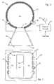
- FIG. 2illustrates another example of a radiant energy emitting system, with certain elements thereof shown in cross-section.
- FIG. 3is a bottom view of the fixture in the system of FIG. 2 .
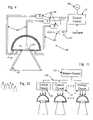
- FIG. 4illustrates another example of a radiant energy emitting system, using fiber optic links from the LEDs to the optical integrating cavity.
- FIG. 5illustrates another example of a radiant energy emitting system, utilizing principles of constructive occlusion.
- FIG. 6is a bottom view of the fixture in the system of FIG. 5 .
- FIG. 7illustrates an alternate example of a radiant energy emitting system, utilizing principles of constructive occlusion.
- FIG. 8is a top plan view of the fixture in the system of FIG. 7 .
- FIG. 9is a functional block diagram of the electrical components, of one of the radiant energy emitting systems, using programmable digital control logic.
- FIG. 10is a circuit diagram showing the electrical components, of one of the radiant energy emitting systems, using analog control circuitry to control the LED sources for adjustment of the spectral characteristic of the combined white light output.
- FIG. 11is a diagram, illustrating a number of radiant energy emitting systems with common control from a master control unit.
- FIG. 12is a layout diagram, useful in explaining an arrangement of a number of the fixtures of the system of FIG. 11 .
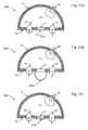
- FIGS. 13A to 13Care cross-sectional views of additional examples, of optical cavity LED light fixtures, with several alternative elements for processing of the combined light emerging from the cavity.
- FIG. 14is a cross-sectional view of another example of an optical cavity LED light fixture, using a collimator, iris and adjustable focusing system to process the combined light output.
- FIG. 15is a cross-sectional view of another example of an optical cavity LED light fixture, as might be used for a “wall-washer” application, using a combination of a white light source and a plurality of primary color light sources.
- FIG. 16is a cross-sectional view of another example of an optical cavity LED light fixture, in this case using a deflector and a combination of a white light source and a plurality of primary color light sources.
- FIG. 1is a cross-sectional illustration of a radiant energy distribution apparatus or system 10 .
- the apparatusemits light in the visible spectrum, although the system 10 may be used for rumination applications and/or with emissions in or extending into the infrared and/or ultraviolet portions of the radiant energy spectrum.
- the illustrated system 10includes an optical cavity 11 having a diffusely reflective interior surface, to receive and combine radiant energy of different colors/wavelengths.
- the cavity 11may have various shapes.
- the illustrated cross-sectionwould be substantially the same if the cavity is hemispherical or if the cavity is semi-cylindrical with the cross-section taken perpendicular to the longitudinal axis.
- the optical cavity in the examples discussed belowis typically an optical integrating cavity.
- the disclosed apparatusmay use a variety of different structures or arrangements for the optical integrating cavity, examples of which are discussed below. At least a substantial portion of the interior surface(s) of the cavity exhibit(s) diffuse reflectivity. It is desirable that the cavity surface have a highly efficient reflective characteristic, e.g. a reflectivity equal to or greater than 90%, with respect to the relevant wavelengths. In the example of FIG. 1 , the surface is highly diffusely reflective to energy in the visible, near-infrared, and ultraviolet wavelengths.
- the cavity 11may be formed of a diffusely reflective plastic material, such as a polypropylene having a 97% reflectivity and a diffuse reflective characteristic.
- a diffusely reflective plastic materialsuch as a polypropylene having a 97% reflectivity and a diffuse reflective characteristic.
- a highly reflective polypropyleneis available from Ferro Corporation—Specialty Plastics Group, Filled and Reinforced Plastics Division, in Evansville, Ind.
- Another example of a material with a suitable reflectivityis SPECTRALON.
- the optical integrating cavitymay comprise a rigid substrate having an interior surface, and a diffusely reflective coating layer formed on the interior surface of the substrate so as to provide the diffusely reflective interior surface of the optical integrating cavity.
- the coating layerfor example, might take the form of a flat-white paint or white powder coat.
- a suitable paintmight include a zinc-oxide based pigment, consisting essentially of an uncalcined zinc oxide and preferably containing a small amount of a dispersing agent.
- the pigmentis mixed with an alkali metal silicate vehicle-binder, which preferably is a potassium silicate, to form the coating material.
- an alkali metal silicate vehicle-binderwhich preferably is a potassium silicate
- the cavity 11 in the apparatus 10is assumed to be hemispherical.
- a hemispherical dome 13 and a substantially flat cover plate 15form the optical cavity 11 .
- At least the interior facing surfaces of the dome 13 and the cover plate 15are highly diffusely reflective, so that the resulting cavity 11 is highly diffusely reflective with respect to the radiant energy spectrum produced by the device 10 .
- the cavity 11is an integrating type optical cavity.
- the dome and platemay be formed as an integral unit.
- the optical integrating cavity 11has an aperture 17 for allowing emission of combined light energy.
- the aperture 17is a passage through the approximate center of the cover plate 15 , although the aperture may be at any other convenient location on the plate 15 or the dome 13 . Because of the diffuse reflectivity within the cavity 11 , light within the cavity is integrated before passage out of the aperture 17 .
- the apparatus 10is shown emitting the combined light downward through the aperture 17 , for convenience.
- the apparatus 10may be oriented in any desired direction to perform a desired application function, for example to provide visible luminance to persons in a particular direction or location with respect to the fixture or to illuminate a different surface such as a wall, floor or table top.
- the optical integrating cavity 11may have more than one aperture 17 , for example, oriented to allow emission of integrated light in two or more different directions or regions.
- the apparatus 10also includes sources of light.
- the apparatusincludes two or more sources 19 of light of different wavelengths.
- the sourcesare LEDs 19 , two of which are visible in the illustrated cross-section.
- the LEDs 19supply light into the interior of the optical integrating cavity 11 .
- the points of emission from the LEDs 19 into the interior of the optical integrating cavity 11are not directly visible through the aperture 17 .
- At least the two illustrated LEDsemit radiant energy of different wavelengths, e.g. Red (R) and Green (G). Additional LEDs of the same or different colors may be provided.
- the cavity 11effectively integrates the energy of different light wavelengths with the substantially white light from source 20 , so that the integrated or combined light energy emitted through the aperture 17 includes the radiant energy of all the various wavelengths in relative amounts substantially corresponding to the relative intensities of input into the cavity 11 .
- the source LEDs 19can include LEDs of any color or wavelength. Typically, an array of LEDs for a visible light application includes at least red, green, and blue LEDs.
- the integrating or mixing capability of the cavity 11serves to project light of any color, including white light, by adjusting the intensity of the various sources coupled to the cavity. Hence, it is possible to control color rendering index (CRI), as well as color temperature.
- CRIcolor rendering index
- the system 10works with the totality of light output from a family of. LEDs 19 to adjust the spectral characteristic of the white light output. However, to provide color adjustment or variability for the white light output, it is not necessary to control the output of individual LEDs 19 or source 20 , except as they contribute to the totality. For example, it is not necessary to modulate the source outputs. Also, the distribution pattern of the individual LEDs and their emission points into the cavity are not significant.
- the LEDs 19can be arranged in any manner to supply radiant energy within the cavity, although it is preferred that direct view of the LEDs from outside the
- light outputs of the LED sources 19are coupled directly to openings at points on the interior of the cavity 11 , to emit radiant energy directly into the interior of the optical integrating cavity.
- the LEDsmay be located to emit light at points on the interior wall of the element 13 , although preferably such points would still be in regions out of the direct line of sight through the aperture 17 .
- the openings for the LEDs 19are formed through the cover, plate 15 . On the plate 15 , the openings/LEDs may be at any convenient locations.
- the source 20 of substantially white input lightmay be one of the LEDs mounted on the cover plate 15 or at any point on the dome 13 .
- the white light sourcemay be any other type of device that produces substantially white light for adjustment or correction by the primary colors from the LEDs 19 .
- suitable white light sources 20include incandescent bulbs, fluorescent bulbs, as well as halide and halogen lamps.
- the apparatusmay include a number of white light sources 20 of the same or different types, coupled to supply light to the integrating cavity 11 .
- the intensity of energy from the white light source 20may be fixed, e.g. by connection to a fixed power supply.
- the power to the white light source 20may be controlled by a variable control, similar to or the same as that provided to one or more of the LEDs 19 by the source 23 and the control circuit 21 .
- the apparatus 10also includes a control circuit 21 coupled to the LEDs 19 for establishing output intensity of radiant energy of each of the LED sources.
- the control circuit 21typically includes a power supply circuit coupled to a source, shown as an AC power source 23 .
- the control circuit 21also includes an appropriate number of LED driver circuits for controlling the power applied to each of the individual LEDs 19 and thus the intensity of radiant energy supplied to the cavity 11 for each different wavelength. Control of the intensity of emission of the sources sets a spectral characteristic of the combined white light emitted through the aperture 17 of the optical integrating cavity.
- the control circuit 21may be responsive to a number of different control input signals, for example, to one or more user inputs as shown by the arrow in FIG. 1 . Although not shown in this simple example, feedback may also be provided. Specific examples of the control circuitry are discussed in more detail later.
- the aperture 17may serve as the system output, directing integrated color light to a desired area or region to be illuminated.
- the aperture 17may have a grate, lens or diffuser (e.g. a holographic element) to help distribute the output light and/or to close the aperture against entry of moisture of debris.
- the system 10includes an additional deflector to distribute and/or limit the light output to a desired field of illumination.
- a later embodiment, for example,uses a colliminator.
- the color integrating energy distribution apparatusmay also utilize one or more conical deflectors having a reflective inner surface, to efficiently direct most of the light emerging from a light source into a relatively narrow field of view.
- the exemplary apparatus shown in FIG. 1also comprises a conical deflector 25 .
- a small opening at a proximal end of the deflectoris coupled to the aperture 17 of the optical integrating cavity 11 .
- the deflector 25has a larger opening 27 at a distal end thereof.
- the angle and distal opening of the conical deflector 25define an angular field of light emission from the apparatus 10 .
- the large opening of the deflectormay be covered with a transparent plate or lens, or covered with a grating, to prevent entry of dirt or debris through the cone into the system and/or to further process the output radiant energy.
- the conical deflector 25may have a variety of different shapes, depending on the particular lighting application.
- the cross-section of the conical deflectoris typically circular.
- the deflectormay be somewhat oval in shape.
- the deflectormay be elongated or even rectangular in cross-section.
- the shape of the aperture 17also may vary, but will typically match the shape of the small end opening of the deflector 25 . Hence, in the example, the aperture 17 would be circular.
- the aperturemay be rectangular.
- the deflector 25comprises a reflective interior surface 29 between the distal end and the proximal end. In some examples, at least a substantial portion of the reflective interior surface 29 of the conical deflector exhibits specular reflectivity with respect to the integrated radiant energy. As discussed in U.S. Pat. No. 6,007,225, for some applications, it may be desirable to construct the deflector 25 so that at least some portion(s) of the inner surface 29 exhibit diffuse reflectivity or exhibit a different degree of specular reflectivity (e.g., quasi-secular), so as to tailor the performance of the deflector 25 to the particular application. For other applications, it may also be desirable for the entire interior surface 29 of the deflector 25 to have a diffuse reflective characteristic. In such cases, the deflector 25 may be constructed using materials similar to those taught above for construction of the optical integrating cavity 11 .
- the large distal opening 27 of the deflector 25is roughly the same size as the cavity 11 . In some applications, this size relationship may be convenient for construction purposes. However, a direct relationship in size of the distal end of the deflector and the cavity is not required. The large end of the deflector may be larger or smaller than the cavity structure. As a practical matter, the size of the cavity is optimized to provide the integration or combination of light colors from the desired number of LED sources 19 and the white light source 20 . The size, angle and shape of the deflector determine the area that will be illuminated by the combined or integrated light emitted from the cavity 11 via the aperture 17 .
- each source of radiant energy of a particular wavelengthcomprises one or more light emitting diodes (LEDs).
- LEDslight emitting diodes
- these sourcesmay comprise one or more LEDs for emitting light of a first color, and one or more LEDs for emitting light of a second color, wherein the second color is different from the first color.
- the apparatusmay include additional sources comprising one or more LEDs of a third color, a fourth color, etc.
- the LED arraymay include LEDs of various wavelengths that cover virtually the entire visible spectrum.
- FIGS. 2 and 3illustrate another example of a radiant energy distribution apparatus or system.
- FIG. 2shows the overall system 30 , including the fixture and the control circuitry. The fixture is shown in cross-section.
- FIG. 4is a bottom view of the fixture.
- the system 30is generally similar the system 10 .
- the system 30may utilize essentially the same type of control circuit 21 and power source 23 , as in the earlier example.
- the shape of the optical integrating cavity and the deflectorare somewhat different.
- the optical integrating cavity 31has a diffusely reflective interior surface.
- the cavity 31has a shape corresponding to a substantial portion of a cylinder.
- the cavity 31appears to have an almost circular shape.
- the cavity 31is formed by a cylindrical element 33 .
- At least the interior surface of the element 33is highly diffusely, reflective, so that the resulting optical cavity 31 is highly diffusely reflective and functions as an integrating cavity, with respect to the radiant energy spectrum produced by the system 30 .
- the optical integrating cavity 31has an aperture 35 for allowing emission of combined radiant energy.
- the aperture 35is a rectangular passage through the wall of the cylindrical element 33 . Because of the diffuse reflectivity within the cavity 31 , light within the cavity is integrated before passage out of the aperture 35 .
- the apparatus 30also includes sources of light energy of different wavelengths and of a substantially white light.
- the sourcescomprise LEDs 37 , 39 .
- the LEDsare mounted in openings through the wall of the cylindrical element 33 , to essentially form two rows of LEDs on opposite sides of the aperture 35 .
- the positions of these openings, and thus the positions of the LEDs 37 and 39typically are such that the LED outputs are not directly visible through the aperture 35 , otherwise the locations are a matter of arbitrary choice.
- the LEDs 37 and 39supply radiant energy into the interior of the optical integrating cavity 31 , through openings at points on the interior surface of the optical integrating cavity not directly visible through the aperture 35 .
- a number of the LEDsemit radiant energy of different wavelengths, and at least one of the LEDs,emits substantially white light.
- arbitrary pairs of the LEDs 37 , 39might emit three different colors of light, e.g. Red, Green and Blue as primary colors.
- the LEDsmay be initially active LEDs, whereas others are initially inactive sleeper LEDs.
- the initially active LEDsmight include two white LEDs, a Red LED, a Green LED and a Blue LED; and the sleeper LEDs might include one Red LED, one Green LED and one Blue LED.
- an additional white LEDalso could be provided, as a sleeper.
- the control circuit 21controls the power provided to each of the LEDs 37 and 39 .
- the cavity 31effectively integrates the energy of the substantially white input light and energy of the different light wavelengths, from the various LEDs 37 and 39 , so that the integrated light energy emitted through the aperture 35 includes the radiant energy of all the various wavelengths.
- Control of the intensity of emission of the sources, by the control circuit 21sets a spectral characteristic of the combined light energy emitted through the aperture 35 . If sleeper LEDs are provided, the control also activates one or more dormant LEDs, on an “as-needed” basis, when extra white output or extra output of a particular wavelength or color is required.
- the color integrating energy distribution apparatus 30may also include a deflector 41 having a specular reflective inner surface 43 , to efficiently direct most of the light emerging from the aperture into a relatively narrow field of view.
- the deflector 41expands outward from a small end thereof coupled to the aperture 35 .
- the deflector 41has a larger opening 45 at a distal end thereof.
- the angle of the side walls of the deflector and the shape of the distal opening 45 of the deflector 41define an angular field of radiant energy emission from the apparatus 30 .
- the deflectormay have a variety of different shapes, depending on the particular lighting application.
- the cross-section of the deflector 41typically appears conical, since the deflector expands outward as it extends away from the aperture 35 .
- the openingsare substantially rectangular, although they may have somewhat rounded corners.
- the deflector 41may be somewhat oval in shape.
- the shapes of the cavity and the aperturemay vary, for example, to have rounded ends, and the deflector may be contoured to match the aperture.
- the deflector 41comprises a reflective interior surface 43 between the distal end and the proximal end.
- the reflective interior surface 43 of the conical deflectorexhibits specular reflectivity with respect to the combined radiant energy, although different reflectivity may be provided, as noted in the discussion of FIG. 1 .
- “sleeper” LEDswould be activated only when needed to maintain the light output, color, color temperature, and/or thermal temperature.
- the system 30could have a color sensor coupled to provide feedback to the control circuit 21 .
- the sensorcould be within the cavity or the deflector or at an outside point illuminated by the integrated light from the fixture.
- the use of the sleeper LEDsgreatly extends the lifecycle of the fixtures. Activating a sleeper (previously inactive) LED, for example, provides compensation for the decrease in output of the originally active LED. There is also more flexibility in the range of intensities that the fixtures may provide.
- the LED sourceswere coupled directly to openings at the points on the interior of the cavity, to emit radiant energy directly into the interior of the optical integrating cavity. It is also envisioned that the sources may be somewhat separated from the cavity, in which case, the device might include optical fibers or other forms of light guides coupled between the sources and the optical integrating cavity, to supply radiant energy from the sources to the emission points into the interior of the cavity.
- FIG. 4depicts such a system 50 , which uses optical fibers.
- the system 50includes an optical integrating cavity 51 , an aperture 53 and a deflector with a reflective interior surface 55 , similar to those in the earlier embodiments.
- the interior surface of the optical integrating cavity 51is highly diffusely reflective, whereas the deflector surface 55 exhibits a specular reflectivity.
- the system 50includes a control circuit 21 and power source 23 , as in the earlier embodiments.
- the radiant energy sourcescomprise LEDs 59 of three different wavelengths, e.g. to provide Red, Green and Blue light respectively.
- the sourcesalso include one or more additional LEDs 61 , including a white LED and possibly including LEDs of a different additional color or for use as ‘sleepers,’ similar to the example of FIGS. 2 and 3 .
- the cover plate 63 of the cavity 51has openings into which are fitted the light emitting distal ends of optical fibers 65 .
- the proximal light receiving ends of the fibers 65are coupled to receive light emitted by the LEDs 59 (and 61 if provided).
- the LED sources 59 , 61may be separate from the chamber 51 , for example, to allow easier and more effective dissipation of heat from the LEDs.
- the fibers 65transport the light from the LED sources 59 , 61 to the cavity 51 .
- the cavity 51integrates the different colors of light from the LEDs as in the earlier examples and supplies combined light, that is to say white light of the selected spectral characteristic, out through the aperture 53 .
- the deflectordirects the combined light to a desired field.
- the intensity control by the circuit 21adjusts the amount or intensity of the light of each type provided by the LED sources and thus controls the spectral characteristic of the combined white light output.
- control circuitrycomprises a color sensor coupled to detect color distribution in the integrated radiant energy.
- Associated logic circuitryresponsive to the detected color distribution, controls the output intensity of the various LEDs, so as to provide a desired color distribution in the integrated radiant energy.
- the logic circuitryis responsive to the detected color distribution to selectively activate the inactive light emitting diodes as needed, to maintain the desired color distribution in the integrated white light energy.
- Constructive Occlusion type transducer systemsutilize an electrical/optical transducer optically coupled to an active area of the system, typically the aperture of a cavity or an effective aperture formed by a reflection of the cavity.
- the systemsutilize diffusely reflective surfaces, such that the active area exhibits a substantially Lambertian characteristic.
- a maskoccludes a portion of the active area of the system, in the examples, the aperture of the cavity or the effective aperture formed by the cavity reflection, in such a manner as to achieve a desired response or output performance characteristic for the system.
- the optical integrating cavitycomprises a base, a mask and a cavity in either the base or the mask.
- the maskwould have a diffusely reflective surface facing toward the aperture.
- the maskis sized and positioned relative to the active area so as to constructively occlude the active area. It may be helpful to consider two examples using constructive occlusion.
- FIGS. 5 and 6depict a first, simple embodiment of a light distributor apparatus or system 70 , for projecting integrated multi-wavelength light with a tailored intensity distribution, using the principles of constructive occlusion.
- the system 70is oriented to provide downward illumination.
- Such a systemmight be mounted in or suspended from a ceiling or canopy or the like.
- the designermay choose to orient the system 70 in different directions, to adapt the system to other lighting applications.
- the lighting system 70includes a base 73 , having or forming a cavity 75 , and adjacent shoulders 77 and 79 , constructed in a manner similar to the elements forming integrating cavities in the earlier examples.
- the interior of the cavity 75is diffusely reflective, and the down-facing surfaces of shoulders 77 and 79 may be reflective. If the shoulder surfaces are reflective, they may be specular or diffusely reflective.
- a mask 81is disposed between the cavity aperture 85 and the field to be illuminated.
- the interior wall of a half-cylindrical base 73forms the cavity; therefore the aperture 85 is rectangular.
- the shoulders 77 formed along the sides of the aperture 85are rectangular. If the base were circular, with a hemispherical cavity, the shoulders typically would form a ring that may partially or completely surround the aperture.
- the cavity 75comprises a substantial segment of a sphere.
- the cavitymay be substantially hemispherical, as in earlier examples.
- the cavity's shapeis not of critical importance. A variety of other shapes may be used.
- the half-cylindrical cavity 75has a rectangular aperture, and if extended longitudinally, the rectangular aperture may approach a nearly linear aperture (slit). Practically any cavity shape is effective, so long as it has a diffuse reflective inner surface.
- a hemisphere or the illustrated half-cylinder shapeare preferred for the ease in modeling for the light output toward the field of intended illumination and the attendant ease of manufacture. Also, sharp corners tend to trap some reflected energy and reduce output efficiency.
- the base 73may be considered to have an active optical area, preferably exhibiting a substantially Lambertian energy distribution.
- the planar aperture 85 formed by the rim or perimeter of the cavity 75forms the active surface with substantially Lambertian distribution of energy emerging through the aperture.
- the cavitymay be formed in the facing surface of the mask.
- the surface of the basemay be a diffusely reflective surface, therefore the active area on the base would essentially be the mirror image of the cavity aperture on the base surface, that is to say the area reflecting energy emerging from the physical aperture of the cavity in the mask.
- the mask 81constructively occludes a portion of the optically active area of the base with respect to the field of intended illumination.
- the optically active areais the aperture 85 of the cavity 75 ; therefore the mask 81 occludes a substantial portion of the aperture 85 , including the portion of the aperture on and about the axis of the mask and cavity system.
- the surface of the mask 81 facing towards the aperture 85is reflective. Although it may be specular, typically this surface is diffusely reflective.
- the relative dimensions of the mask 81 and aperture 85control the constructive occlusion performance characteristics of the lighting system 70 .
- Certain combinations of these parametersproduce a relatively uniform emission intensity with respect to angles of emission, over a wide portion of the field of view about the system axis (vertically downward in FIG. 5 ), covered principally by the constructive occlusion.
- Other combinations of size and heightresult in a system performance that is uniform with respect to a wide planar surface perpendicular to the system axis at a fixed distance from the active area.
- the shoulders 77 , 79also are reflective and therefore deflect at least some light downward.
- the shoulders (and side surfaces of the mask)provide additional optical processing of combined light from the cavity.
- the angles of the shoulders and the reflectivity of the surfaces thereof facing toward the region to be illuminated by constructive occlusionalso contribute to the intensity distribution over that region.
- the reflective shouldersare horizontal, although they may be angled somewhat downward from the plane of the aperture.
- the interior space formed between the cavity 75 and the facing surface of the mask 81operates as an optical integrating cavity, in essentially the same manner, as the integrating cavities in the previous embodiments.
- the LEDs 87provide light of a number of different colors, and thus of different wavelengths. At least one of the LEDs also provides substantially white light:
- the optical cavitycombines the light of multiple colors supplied from the LEDs 87 .
- the control circuit 21controls the amount of each color of light supplied to the chamber and thus the proportion thereof included in the combined output light.
- the constructive occlusionserves to distribute that light in a desired manner over a field or area that the system 70 is intended to illuminate, with a tailored intensity distribution.
- the LEDs 87could be located at (or coupled by optical fiber to emit light) from any location or part of the surface of the cavity 75 .
- the LED outputsare not directly visible through the un-occluded portions of the aperture 85 (between the mask and the edge of the cavity).
- the easiest way to so position the LED outputsis to mount the LEDs 87 (or provide fibers or the like) so as to supply light to the chamber through openings through the mask 81 .
- FIG. 6also provides an example of an arrangement of the LEDs in which there are both active and inactive (sleeper) LEDs of the various colors.
- the active part of the array of LEDs 87includes two Red LEDs (R), one Green LED (G) and one Blue LED (B).
- the initially inactive part of the array of LEDs 87includes two Red sleeper LEDs (RS), one Green sleeper LED (GS) and one Blue sleeper LED (BS).
- the systemincludes an active white LED (W) and a sleeper LED (WS) for providing the substantially white input light on an as-needed basis. If other wavelengths or white light sources are desired, the apparatus may include an active LED of the other color as well as a sleeper LED of the other color.
- the precise number, type, arrangement and mounting technique of the LEDs and the associated ports through the mask 81are not critical. The number of LEDs, for example, is chosen to provide a desired level of output energy (intensity), for a given application.
- the system 70includes a control circuit 21 and power source 23 . These elements control the operation and output intensity of each LED 87 . The individual intensities determine the amount of each color light included in the integrated and distributed output.
- the control circuit 21functions in essentially the same manner as in the other examples.
- FIGS. 7 and 8illustrate a second constructive occlusion example.
- the physical cavityis actually formed in the mask, and the active area of the base is a flat reflective panel of the base.
- the illustrated system 90comprises a flat base panel 91 , a mask 93 , LED light sources 95 , and a conical deflector 97 .
- the system 90is circularly symmetrical about a vertical axis, although it could be rectangular or have other shapes.
- the base 91includes a flat central region 99 between the walls of the deflector 97 .
- the region 99is reflective and forms or contains the active optical area on the base facing toward the region or area to be illuminated by the system 90 .
- the mask 93is positioned between the base 91 and the region to be illuminated by constructive occlusion.
- the mask 93is above the active optical area 99 of the base 91 , for example to direct light toward a ceiling for indirect illumination.
- the mask and cavity systemcould be inverted to serve as a downlight for task lighting applications, or the mask and cavity system could be oriented to emit light in directions appropriate for other applications.
- the mask 93contains the diffusely reflective cavity 101 , constructed in a manner similar to the integrating cavities in the earlier examples.
- the physical aperture 103 of the cavity 101 and of any diffusely reflective surface(s) of the mask 93 that may surround that apertureform an active optical area on the mask 93 .
- Such an active area on the maskfaces away from the region to be illuminated and toward the active surface 99 on the base 91 .
- the surface 99is reflective, preferably with a diffuse characteristic.
- the surface 99 of the base 91essentially acts to produce a diffused mirror image of the mask 93 with its cavity 101 as projected onto the base area 99 .
- the reflection formed by the active area of the basebecomes the effective aperture of the optical integrating cavity (between the mask and base) when the fixture is considered from the perspective of the area of intended illumination.
- the surface area 99reflects energy emerging from the aperture 103 of the cavity 101 in the mask 93 .
- the mask 93in turn constructively occludes light diffused from the active base surface 99 with respect to the region illuminated by the system 90 .
- the dimensions and relative positions of the mask and active region on the basecontrol the performance of the system, in essentially the same manner as in the mask and cavity system of FIGS. 6 and 7 .
- the system 90includes a control circuit 21 and associated power source. 23 , for supplying controlled electrical power to the LED sources 95 .
- the LEDsemit light through openings through the base 91 , preferably at points not directly visible from outside the system.
- the LEDs 95supply substantially white light as well as various wavelengths of primary color light, and the circuit 21 controls the power of each LED, to control the amount of each color of light in the combined output, as discussed above relative to the other examples.
- the base 91could have a flat ring-shaped shoulder with a reflective surface. In this example, however, the shoulder is angled toward the desired field of illumination to form a conical deflector 97 .
- the inner surface of the deflector 97is reflective, as in the earlier examples.
- the deflector 97has the shape of a truncated cone, in this example, with a circular lateral cross section.
- the conehas two circular openings.
- the conetapers from the large end opening to the narrow end opening, which is coupled to the active area 99 of the base 91 .
- the narrow end of the deflector conereceives light from the surface 99 and thus from diffuse reflections between the base and the mask.
- the entire area of the inner surface of the cone 97is reflective. At least a portion of the reflective surface is specular, as in the deflectors of the earlier examples.
- the angle of the wall(s) of the conical deflector 97substantially corresponds to the angle of the desired field of view of the illumination intended for the system 90 . Because of the reflectivity of the wall of the cone 97 , most if not all of the light reflected by the inner surface thereof would at least achieve an angle that keeps the light within the field of view.
- the LED light sources 95emit multiple wavelengths of light into the mask cavity 101 , and at least one LED emits substantially white light.
- the light sources 95may direct some light toward the inner surface of the deflector 97 .
- Light rays impacting on the diffusely reflective surfaces, particularly those on the inner surface of the cavity 101 and the facing surface 99 of the base 91reflect and diffuse one or more times within the confines of the system and emerge through the gap between the perimeter of the active area 99 of the base and the outer edge of the mask 93 .
- the mask cavity 101 and the base surface 99function as an optical integrating cavity with respect to the light of various wavelengths and the substantially white light, and the gap becomes the actual integrating cavity aperture from which adjusted white light of the selected spectral characteristic emerges.
- the white light emitted through the gap and/or reflected from the surface of the inner surface of the deflector 97irradiates a region (upward in the illustrated orientation) with a desired intensity distribution and with a desired spectral characteristic, essentially as in the earlier examples.
- the inventive deviceshave numerous applications, and the output intensity and spectral characteristic may be tailored and/or adjusted to suit the particular application.
- the intensity of the integrated white light emitted through the aperturemay be at a level for use in a rumination application or at a level sufficient for a task lighting application.
- the controlmay maintain a set color characteristic in response to feedback from a color sensor.
- the control circuitrymay also include a temperature sensor.
- the logic circuitryis also responsive to the sensed temperature, e.g. to reduce intensity of the source outputs to compensate for temperature increases.
- the control circuitrymay include an appropriate device for manually setting the desired spectral characteristic, for example, one or more variable resistors or one or more dip switches, to allow a user to define or select the desired color distribution.
- control circuitrymay include a data interface coupled to the logic circuitry, for receiving data defining the desired color distribution.
- a data interfacecoupled to the logic circuitry, for receiving data defining the desired color distribution.
- Such an interfacewould allow input of control data from a separate or even remote device, such as a personal computer, personal digital assistant or the like.
- a number of the devices, with such data interfaces,may be controlled from a common central location or device.
- the controlmay be somewhat static, e.g. set the desired color reference index or desired color temperature and the overall intensity, and leave the device set-up in that manner for an indefinite period.
- the apparatusalso may be controlled dynamically, for example, to provide special effects lighting. Also, such light settings are easily recorded and reused at a later time or even at a different location using a different system.
- FIG. 9is a block diagram of exemplary circuitry for the sources and associated control circuit, providing digital programmable control, which may be utilized with a light integrating fixture of the type described above.
- the sources of radiant energy of the various typestakes the form of an LED array 111 .
- the array 111comprises two or more LEDs of each of the three primary colors, red green and blue, represented by LED blocks 113 , 115 and 117 .
- the arraymay comprise six red LEDs 113 , three green LEDs 115 and three blue LEDs 117 .
- the LED array in this examplealso includes a number of additional or “other” LEDs 119 .
- the additional LEDsinclude one or more ‘white’ LEDs, as the source of substantially white input light.
- the primary colors LEDsprovide light for selectable color adjustment and/or correction.
- additional LEDsthere are several other types of additional LEDs that may be of interest in the present discussion.
- One type of additional LEDprovides one or more additional wavelengths of radiant energy for integration within the chamber.
- the additional wavelengthsmay be in the visible portion of the light spectrum, to allow a greater degree of color adjustment.
- the additional wavelength LEDsmay provide energy in one or more wavelengths outside the visible spectrum, for example, in the infrared range or the ultraviolet range.
- the second type of additional LED that may be included in the systemis a sleeper LED. As discussed above, some LEDs would be active, whereas the sleepers would be inactive, at least during initial operation. Using the circuitry of FIG. 10 as an example, the Red LEDs 113 , Green LEDs 115 and Blue LEDs 117 might normally be active. One or more of the LEDs 119 would be sleeper LEDs, typically including one or more LEDs of each color used in the particular system and possibly one or more white LEDs.
- the electrical components shown in FIG. 10also include an LED control system 120 .
- the system 120includes driver circuits for the various LEDs and a microcontroller.
- the driver circuitssupply electrical current to the respective LEDs 113 to 119 to cause the LEDs to emit light.
- the driver circuit 121drives the Red LEDs 113
- the driver circuit 123drives the green LEDs 115
- the driver circuit 125drives the Blue LEDs 117 .
- the driver circuit 1 . 27provides electrical current to the other LEDs 119 . If the other LEDs provide another color of light, and are connected in series, there may be a single driver circuit 127 . If the LEDs are sleepers, it may be desirable to provide a separate driver circuit 127 for each of the LEDs 119 .
- the intensity of the emitted light of a given LEDis proportional to the level of current 'supplied by the respective driver circuit.
- each driver circuitis controlled by the higher level logic of the system.
- that logicis implemented by a programmable microcontroller 129 , although those skilled in the art will recognize that the logic could take other forms, such as discrete logic components, an application specific integrated circuit (ASIC), etc.
- the LED driver circuits and the microcontroller 129receive power from a power supply 131 , which is connected to an appropriate power source (not separately shown).
- the power sourcewill be an AC line current source, however, some applications may utilize DC power from a battery or the like.
- the power supply 129converts the voltage and current from the source to the levels needed by the driver circuits 121 - 127 and the microcontroller 129 .
- a programmable microcontrollertypically includes or has coupled thereto random-access memory (RAM) for storing data and read-only memory (ROM) and/or electrically erasable read only memory (EEROM) for storing control programming and any pre-defined operational parameters, such as pre-established light ‘recipes.’
- RAMrandom-access memory
- ROMread-only memory
- EEROMelectrically erasable read only memory
- the microcontroller 129itself comprises registers and other components for implementing a central processing unit (CPU) and possibly an associated arithmetic logic unit.
- the CPUimplements the program to process data in the desired manner and thereby generate desired control outputs.
- the microcontroller 129is programmed to control the LED driver circuits 121 - 127 to set the individual output intensities of the LEDs to desired levels, so that the combined white light emitted from the aperture of the cavity has a desired spectral characteristic and a desired overall intensity.
- the microcontroller 129may be programmed to essentially establish and maintain or preset a desired ‘recipe’ or mixture of the available wavelengths provided by the LEDs used in the particular system.
- the microcontroller 129receives control inputs specifying the particular ‘recipe’ or mixture, as will be discussed below. To insure that the desired mixture is maintained, the microcontroller receives a color feedback signal from an appropriate color sensor.
- the microcontrollermay also be responsive to a feedback signal from a temperature sensor, for example, in or near the optical integrating cavity.
- the electrical systemwill also include one or more control inputs 133 for inputting information instructing the microcontroller 129 as to the desired operational settings.
- control inputs 133for inputting information instructing the microcontroller 129 as to the desired operational settings.
- a number of different types of inputsmay be used and several alternatives are illustrated for convenience.
- a given installationmay include a selected one or more of the illustrated control input mechanisms.
- user inputsmay take the form of a number of potentiometers 135 .
- the numberwould typically correspond to the number of different light wavelengths provided by the particular LED array 111 .
- the potentiometers 135typically connect through one or more analog to digital conversion interfaces provided by the microcontroller 129 (or in associated circuitry). To set the parameters for the integrated light output, the user adjusts the potentiometers 135 to set the intensity for each color.
- the microcontroller 129senses the input settings and controls the LED driver circuits accordingly, to set corresponding intensity levels for the LEDs providing the light of the various wavelengths.
- Another user input implementationmight utilize one or more dip switches 137 .
- the memory used by the microcontroller 129would store the necessary intensity levels for the different color LEDs in the array 111 for each recipe. Based on the input code, the microcontroller 129 retrieves the appropriate recipe from memory. Then, the microcontroller 129 controls the LED driver circuits 121 - 127 accordingly, to set corresponding intensity levels for the LEDs 113 - 119 providing the light of the various wavelengths.
- the microcontroller 129may be responsive to control data supplied from a separate source or a remote source.
- some versions of the systemwill include one or more communication interfaces.
- a wired interface 139One example of a general class of such interfaces is a wired interface 139 .
- wired interfacetypically enables communications to and/or from a personal computer or the like, typically within the premises in which the fixture operates. Examples of such local wired interfaces include USB, RS-232, and wire-type local area network (LAN) interfaces.
- LANlocal area network
- Wireless interfacesfor example, use radio frequency (RF) or infrared (IR) links.
- the wireless communicationsmay be local on-premises communications, analogous to a wireless local area network (WLAN).
- the wireless communicationsmay enable communication with a remote device outside the premises, using wireless links to a wide area network.
- the electrical componentsmay also include one or more feedback sensors 143 , to provide system performance measurements as feedback signals to the control logic, implemented in this example by the microcontroller 129 .
- the set 143 of feedback sensorsincludes a color sensor 145 and a temperature sensor 147 .
- other sensorssuch as an overall intensity sensor may be used.
- the sensorsare positioned in or around the system to measure the appropriate physical condition, e.g. temperature, color, intensity, etc.
- the color sensor 145is coupled to detect color distribution in the integrated radiant energy.
- the color sensormay be coupled to sense energy within the optical integrating cavity, within the deflector (if provided) or at a point in the field illuminated by the particular system.
- Various examples of appropriate color sensorsare known.
- the color sensormay be a digital compatible sensor, of the type sold by TAOS, Inc;
- Another suitable sensormight use the quadrant light detector disclosed in U.S. Pat. No. 5,877,490, with appropriate color separation on the various light detector elements (see U.S. Pat. No. 5,914,487 for discussion of the color analysis).
- the associated logic circuitryresponsive to the detected color distribution, controls the output intensity of the various LEDs, so as to provide a desired color distribution in the integrated white light energy, in accord with appropriate settings.
- the logic circuitryis responsive to the detected color distribution to selectively activate the inactive light emitting diodes as needed, to maintain the desired color distribution in the integrated light energy.
- the color sensormeasures the color of the integrated white light energy produced by the system and provides a color measurement signal to the microcontroller 129 . If using the TAOS, Inc. color sensor, for example, the signal is a digital signal derived from a color to frequency conversion.
- the temperature sensor 147may be a simple thermoelectric transducer with an associated analog to digital converter, or a variety of other temperature detectors may be used.
- the temperature sensoris positioned on or inside of the fixture, typically at a point that is near the LEDs or other sources that produce most of the system heat.
- the temperature sensor 147provides a signal representing the measured temperature to the microcontroller 129 .
- the system logichere implemented by the microcontroller 129 , can adjust intensity of one or more of the LEDs in response to the sensed temperature, e.g. to reduce intensity of the source outputs to compensate for temperature increases.
- the program of the microcontroller 129would typically manipulate the intensities of the various LEDs so as to maintain the desired color balance between the various wavelengths of light used in the system, even though it may vary the overall intensity with temperature. For example, if temperature is increasing due to increased drive current to the active LEDs (with increased age or heat), the controller may deactivate one or more of those LEDs and activate a corresponding number of the sleepers, since the newly activated sleeper(s) will provide similar output in response to lower current and thus produce less heat.
- FIG. 10is a circuit diagram of a simple analog control for a lighting apparatus (e.g. of the type shown at 19 in FIG. 1 ) using Red, Green and Blue LEDs. Assume for this discussion that a separate fixed or variable source (not shown) supplies power to a light bulb serving as the white light source. The user establishes the levels of intensity for each type of LED light emission (Red, Green or Blue) by operating a corresponding one of the potentiometers.
- a lighting apparatuse.g. of the type shown at 19 in FIG. 1
- Red, Green and Blue LEDsAssume for this discussion that a separate fixed or variable source (not shown) supplies power to a light bulb serving as the white light source. The user establishes the levels of intensity for each type of LED light emission (Red, Green or Blue) by operating a corresponding one of the potentiometers.
- the circuitryessentially comprises driver circuits for supplying adjustable power to two or three sets of LEDs (Red, Green and Blue) and analog logic circuitry for adjusting the output of each driver circuit in accord with the setting of a corresponding potentiometer. Additional potentiometers and associated circuits would be provided for additional colors of LEDs. Those skilled in the art should be able to implement the illustrated analog driver and control logic of FIG. 10 without further discussion.
- control circuitrymay include a communication interface 139 or 141 allowing the microcontroller 129 to communicate with another processing system.
- FIG. 11illustrates an example in which control circuits 21 of a number of the radiant energy generation systems with the light integrating and distribution type fixture communicate with a master control unit 151 via a communication network 153 .
- the master control unit 151typically is a programmable computer with an appropriate user interface, such as a personal computer or the like.
- the communication network 153may be a LAN or a wide area network, of any desired type. The communications allow an operator to control the color and output intensity of all of the linked systems, for example to provide combined lighting effects.
- the commonly controlled lighting systemsmay be arranged in a variety of different ways, depending on the intended use of the systems.
- FIG. 13shows a somewhat random arrangement of lighting systems.
- the circlesrepresent the output openings of those systems, such as the large opening of the system deflectors.
- the dotted linesrepresent the fields of the emitted radiant energy.
- Such an arrangement of lighting systemsmight be used to throw desired lighting on a wall or other object and may allow the user to produce special lighting effects at different times.
- Another applicationmight involve providing different color lighting for different speakers during a television program, for example, on a news program, panel discussion or talk show.
- a deflector, mask or shoulderwas used to provide further optical processing of the integrated white light emerging from the aperture of the fixture.
- a variety of other optical processing devicesmay be used in place of or in combination with any of those optical processing elements. Examples include various types of diffusers, collimators, variable focus mechanisms, and iris or aperture size control mechanisms. Several of these examples are shown in FIGS. 15-16 .
- FIGS. 13A to 13Care cross-sectional views of several examples of optical cavity LED fixtures using various forms of secondary optical processing elements to process the integrated energy emitted through the aperture. Although similar fixtures may process and emit other radiant energy spectra, for discussion here we will assume these “lighting” fixtures process and emit white light in the visible part of the spectrum. These first three examples are similar to each other, and the common aspects are described first.
- Each fixture 250( 250 a to 250 c in FIGS. 13A to 13C , respectively) includes an optical integrating cavity 11 , at least one source 20 of white light and LEDs 19 , similar to those in the example of FIG. 1 .
- a power source and control circuit similar to those used in the earlier examplesprovide the drive currents for the LEDs, and in view of the similarity, the power source and control circuit are omitted from these figures, to simplify the illustrations.
- each light fixture 250 a to 250 cincludes an optical integrating cavity 11 , formed by a dome 11 and a cover plate 15 .
- the surfaces of the dome 13 and cover 15 forming the interior surface(s) of the cavity 11are diffusely reflective.
- One or more apertures 17in these examples formed through the plate 15 , provide a light passage for transmission of reflected and integrated white light outward from the cavity 11 . Materials, positions, orientations and possible shapes for the elements 11 to 17 have been discussed above.
- each fixture 250 a to 250 cincludes a number of LEDs 19 emitting light of different wavelengths into the cavity 11 , as in the example of FIG. 1 .
- a number of the LEDswill be active, from initial start-up, whereas others may initially be inactive ‘sleepers,’ as also discussed above.
- the possible combinations and positions of the LEDs 19have been discussed in detail above, in relation to the earlier examples.
- the LEDs 19emit light of multiple colors into the interior of the optical integrating cavity. Control of the amplitudes of the drive currents applied to the LEDs 19 controls the amount of each light color supplied into the cavity 11 .
- a source 20such as another LED or an appropriate lamp or bulb, supplies substantially white light into the cavity 11 .
- the cavity 11integrates the various amounts of light from the different sources into a combined white light of the selected spectral characteristic for emission through the aperture 17 .
- the fixture 250 aincludes a lens 251 a in or covering the aperture 17 .
- the lensmay take any convenient form, for focusing or diffusing the emitted combined light, as desired for a particular application of the fixture 250 a .
- the lens 251 amay be clear or translucent.
- the fixture 250 bincludes a curved transmissive diffuser 251 a covering the aperture 17 .
- the diffusermay take any convenient form, for example, a white or clear dome of plastic or glass. Alternatively, the dome may be formed of a prismatic material.
- the element 251 bdiffuses the emitted white light, as desired for a particular application of the fixture 250 b .
- the dome shaped diffusermay cover just the aperture, as shown at 251 b , or it may cover the backs of the LEDs 19 as well.
- a holographic diffraction plate or grading 251 cserves as the optical output processing element in the fixture 250 c .
- the holographic gratingis another form of diffuser.
- the holographic diffuser 251 cis located in the aperture 17 or attached to the plate 15 to cover the aperture 17 .
- a holographic diffuserprovides more precise control over the diffuse area of illumination and increases transmission efficiency.
- Holographic diffusers and/or holographic filmsare available from a number of manufacturers, including Edmund Industrial Optics of Barrington, N.J.
- a fiber optic bundlemay be used to channel the light to a desired point and/or in a desired direction.
- the exemplary systems discussed hereinmay have any size desirable for any particular application.
- a systemmay be relatively large, for lighting a room or providing spot or flood lighting.
- the systemalso may be relatively small, for example, to provide a small pinpoint of light, for an indicator or the like.
- the system 250 a with or even without the lens,is particularly amenable to miniaturization.
- the LEDsinstead of a plate to support the LEDs, the LEDs could be manufactured on a single chip. If it was not convenient to provide the aperture through the chip, the aperture could be formed through the reflective dome.
- FIG. 14illustrates another example of a “lighting” system 260 with an optical integrating cavity LED light fixture, having yet other elements to optically process the combined color light output.
- the system 260includes an optical integrating cavity and LEDs similar to those in the examples of FIG. 1 and FIGS. 13A to 13C , and like reference numerals are used to identify the corresponding components.
- the light fixtureincludes an optical integrating cavity 11 , formed by a dome 11 and a cover plate 15 .
- the surfaces of the dome 13 and cover 15 forming the interior surface(s) of the cavity 11are diffusely reflective.
- One or more apertures 17in this example formed through the plate 15 , provide a light passage for transmission of reflected and integrated white light outward from the cavity 11 .
- Materials, possible shapes, positions and orientations for the elements 11 to 17have been discussed above.
- the system 260includes a number of LEDs 19 emitting light of different wavelengths into the cavity 11 . The possible combinations and positions of the LEDs 19 have been discussed in detail above, in relation to the earlier examples.
- the LEDs 19emit light of multiple colors into the interior of the optical integrating cavity 11 .
- the light colorsare in the visible portion of the radiant energy spectrum.
- Control of the amplitudes of the drive currents applied to the LEDs 19controls the amount of each light color supplied into the cavity 11 .
- a source 20such as another LED or an appropriate lamp or bulb, supplies substantially white light into the cavity 11 .
- a number of the LEDswill be active, from initial start-up, whereas others may initially be inactive ‘sleepers,’ as discussed above.
- the cavity 11integrates the various amounts of light of the different colors with the substantially white input light, to form a combined white light of a selected color balance or temperature, for emission through the aperture 17 .
- the system 260also includes a control circuit 262 coupled to the LEDs 19 for establishing output intensity of radiant energy of each of the LED sources.
- the control circuit 262typically includes a power supply circuit coupled to a source, shown as an AC power source 264 , although the power source 264 may be a DC power source. In either case, the circuit 262 may be adapted to process the voltage from the available source to produce the drive currents necessary for the LEDs 19 (and possibly to the source 20 ).
- the control circuit 262includes an appropriate number of LED driver circuits, as discussed above relative to FIGS. 9 and 10 , for controlling the power applied to each of the individual LEDs 19 and thus the intensity of radiant energy supplied to the cavity 11 for each different type/color of light. Control of the intensity of emission of each of the LED sources sets a spectral characteristic of the combined white light energy emitted through the aperture 17 of the optical integrating cavity 11 , in this case, the color characteristic(s) of the visible white light output.
- the control circuit 262may respond to a number of different control input signals, for example, to one or more user inputs as shown by the arrow in FIG. 14 .
- Feedbackmay also be provided by a temperature sensor (not shown in this example) or one or more color sensors 266 .
- the color sensor(s) 266may be located in the cavity or in the element or elements for processing light emitted through the aperture 17 .
- the plate 15 and/or dome 13may pass some of the integrated light from the cavity, in which case, it is actually sufficient to place the color light sensor(s) 266 adjacent any such transmissive point on the outer wall that forms the cavity.
- the sensor 266is shown attached to the plate 15 . Details of the control feedback have been discussed earlier, with regard to the circuitry in FIG. 9 .
- FIG. 14utilizes a different arrangement for directing and processing the white light after emission from the cavity 11 through the aperture 17 .
- This system 260utilizes a collimator 253 , an adjustable iris 255 and an adjustable focus lens system 259 .
- the collimator 253may have a variety of different shapes, depending on the desired application and the attendant shape of the aperture 17 . For ease of discussion here, it is assumed that the elements shown are circular, including the aperture 17 . Hence, in the example, the collimator 253 comprises a substantially cylindrical tube, having a circular opening at a proximal end coupled to the aperture 17 of the optical integrating cavity 11 .
- the system 260emits white light of a selected desired spectral character, toward a desired field of illumination, via the circular opening at the distal end of the collimator 253 .
- the interior surface of the collimator 253is reflective.
- the reflective inner surfacemay be diffusely reflective or quasi-specular.
- the interior surface of the deflector/collimator element 253is specular.
- the tube forming the collimator 253also supports a series of elements for optically processing the collimated and integrated light. Those skilled in the art will be familiar with the types of processing elements that may be used, but for purposes of understanding, it may be helpful to consider two specific types of such elements.
- the tube forming the collimator 253supports a variable iris.
- the iris 257represents a secondary aperture, which effectively limits the output opening and thus the intensity of white light that may be output by the system 260 .
- the irismay be mounted in or serve as the aperture 17 .
- a circuit 257controls the size or adjustment of the opening of the iris 255 .
- the useractivates the LED control circuit (see e.g. 21 in FIG. 1 ) to set the color balance or temperature of the output light, that is to say, so that the system 260 outputs white light of a desired color variation.
- the overall intensity of the output lightis then controlled through the circuit 257 and the iris 255 . Opening the iris 255 wider provides higher output intensity, whereas reducing the iris opening size decreases intensity of the light output.
- the tube forming the collimator 253also supports one or more lens elements of the adjustable focusing system 259 , shown by way of example as two lenses 261 and 263 . Spacing between the lenses and/or other parameters of the lens system 259 are adjusted by a mechanism 265 , in response to a signal from a focus control circuit 267 .
- the elements 261 to 267 of the system 259are shown here by way of example, to represent a broad class of elements that may be used to variably focus the emitted light in response to a control signal or digital control information or the like. If the system 260 serves as a spot light, adjustment of the lens system 259 effectively controls the size of the spot on the target object or subject that the system illuminates.
- other optical processing elementsmay be provided, such as a mask to control the shape of the illumination spot or various shutter arrangements for beam shaping.
- control circuits 257 and 267the functions of these circuits may be integrated together with each other or integrated into the circuit 262 that controls the operation of the LEDs 19 .
- the systemmight use a single microprocessor or similar programmable microcontroller, which would run control programs for the LED drive currents, the iris control and the focus control.
- the optical integrating cavity 11 and the LEDs 19produce white light of a precisely controlled composite color balance or temperature.
- control of the LED currentscontrols the amount of each color of light integrated into the white output.
- Control of the opening provided by the iris 255then controls the intensity of the integrated light output of the system 260 .
- Control of the focusing by the system 259enables control of the breadth of the light emissions and thus the spread of the area or region to be illuminated by the system 260 .
- Other elementsmay be provided to control beam shape.
- Professional production lighting applications for such a systeminclude theater or studio lighting, for example, where it is desirable to control the color (temperature or balance), intensity and the size of a spotlight beam.
- the LED control circuit 257By connecting the LED control circuit 257 , the iris control circuit 257 and the focus control circuit 267 to a network similar to that in FIG. 11 , it becomes possible to control color characteristics of the white light, intensity and the spot size of many lights from a remote network terminal, for example, at an engineer's station in the studio or theater.
- FIG. 15is a cross sectional view of an example of a wall washer type fixture 350 .
- the fixture 350includes an optical integrating cavity 351 having a diffusely reflective inner surface, as in the earlier examples.
- the cavity 351has a substantially rectangular cross-section.
- the fixture 350includes at least one white light source, represented by the white LED 355 .
- the fixturealso includes several LEDs 359 of the various primary colors, typically red (R), green (G) and blue (B, not visible in this cross-sectional view).
- the LEDs 359include both initially-active LEDs and sleeper LEDs, and the LEDs 359 are similar to those in the earlier examples.
- the LEDsemit controlled amounts of multiple colors of light into the optical integrating cavity 351 formed by the inner surfaces of a rectangular member 353 .
- a power source and control circuit similar to those used in the earlier examplesprovide the drive currents-for the LEDs 359 , and in this example, that same circuit controls the drive current applied to the white LED 355 . In view of the similarity, the power source and control circuit are omitted from FIG. 15 , to simplify the illustration.
- One or more apertures 357provide light passage for transmission of reflected and integrated white light outward from the cavity 351 .
- the aperturemay be laterally centered, as in the earlier examples; however, in this example, the aperture is off-center to facilitate a light-through to the left (in the illustrated orientation).
- Materials for construction of the cavity and the types of LEDs that may be usedare similar to those discussed relative to the earlier examples.
- the fixture 350is intended to principally provide white light, for example, to illuminate a wall or product to the left and somewhat above the fixture.
- the presence of the white light source 355increases the intensity of white light that the fixture produces.
- the control of the outputs of the primary color LEDs 359allows the operator to correct for any variations of the white light from the source 355 from normal white light and/or to adjust the color balance/temperature of the light output.
- the white light source 355is an LED as shown, the white light it provides tends to be rather blue.
- the intensities of light output from the LEDs 359can be adjusted to compensate for this blueness, for example, to provide a light output approximating sunlight or light from a common incandescent source, as or when desired.
- the fixture 350may be used to illuminate products, e.g. as displayed in a store or the like, although it may be rotated or inverted for such a use.
- productse.g. as displayed in a store or the like, although it may be rotated or inverted for such a use.
- Different productsmay present a better impression if illuminated by white light having a different balance. For example, fresh bananas may be more attractive to a potential customer when illuminated by light having more yellow tones. Soda sold in red cans, however, may be more attractive to a potential customer when illuminated by light having more red tones.
- the usercan adjust the intensities of the light outputs from the LEDs 359 and/or 355 to produce light that appears substantially white if observed directly by a human/customer but provides the desired highlighting tones and thereby optimizes lighting of the particular product that is on display.
- the fixture 350may have any desired output processing element(s), as discussed above with regard to various earlier examples.
- the fixture 350includes a deflector to further process and direct the light emitted from the aperture 357 of the optical integrating cavity 351 , in this case toward a wall or product somewhat to the left of and above the fixture 350 .
- the deflectoris formed by two opposing panels 365 a and 365 b having reflective inner surfaces 365 a and 365 b .
- the illustrationshows the panel 365 a , 365 b as relatively flat panels set at somewhat different angle extending to the left, in the illustrated orientation.
- the fixturemay be turned at any desired angle or orientation to direct the light to a particular region or object to be illuminated by the fixture, in a given application.
- each panel 365 a , 365 bhas a reflective interior surface 369 a , 369 b .
- all or portions of the deflector surfacesmay be diffusely reflective, quasi-specular or specular.
- the deflector panel surface 369 bis diffusely reflective, and the deflector panel surface 369 a has a specular reflectivity, to optimize distribution of emitted light over the desired area of the wall illuminated by the fixture 350 .
- the output opening of the deflector 365may be covered with a grating, a plate or lens, although in the illustrated wall washer example, such an element is omitted.
- FIG. 16is a cross-sectional view of another example of an optical integrating cavity type light fixture 370 .
- This exampleuses a deflector and lens to optically process the light output, and like the example of FIG. 23 the fixture 370 includes LEDs to produce various colors of light in combination with a white light source.
- the fixture 370includes an optical integrating cavity 371 , formed by a dome and a cover plate, although other structures may be used to form the cavity.
- the surfaces of the dome and cover forming the interior surface(s) of the cavity 371are diffusely reflective.
- One or more apertures 377in this example formed through the cover plate, provide a light passage for transmission of reflected and integrated light outward from the cavity 371 . Materials, sizes, orientation,.positions and possible shapes for the elements forming the cavity and the types/numbers of LEDs have been discussed above.
- the fixture 370includes at least one white light source.
- the white light sourcecould comprise one or more LEDs, as in several of the previous examples, in this embodiment, the white light source comprises a lamp 375 .
- the lampmay be any convenient form of light bulb, such as an incandescent or fluorescent light bulb; and there may be one, two or more bulbs to produce a desired amount of white light.
- a preferred example of the lamp 375is a quartz halogen light bulb.
- the fixturealso includes several LEDs 379 of the various primary colors, typically red (R), green (G) and blue (B, not visible in this cross-sectional view), although additional colors may be provided or other color LEDs may be substituted for the RGB LEDs. Some LEDs will be active from initial operation. Other LEDs may be held in reserve as sleepers.
- the LEDs 379are similar to those in the earlier examples, for emitting controlled amounts of multiple colors of light into the optical integrating cavity 371 .
- a power source and control circuit similar to those used in the earlier examplesprovide the drive currents for the LEDs 359 .
- the power source and control circuit for the LEDsare omitted from FIG. 16 , to simplify the illustration.
- the lamp 375may be controlled by the same or similar circuitry, or the lamp may have a fixed power source.
- the white light source 375may be positioned at a point that is not directly visible through the aperture 377 similar to the positions of the LEDs 379 . However, for some applications requiring relatively high white light output intensity, it may be preferable to position the white light source 375 to emit a substantial portion of its light output directly through the aperture 377 as in this particular example.
- the fixture 370may incorporate any of the further optical processing elements discussed above.
- the fixturemay include a variable iris and variable focus system, as in the embodiment of FIG. 14 .
- the fixture 370includes a deflector 385 to further process and direct the light emitted from the aperture 377 of the optical integrating cavity 371 .
- the deflector 385has a reflective interior surface 389 and expands outward laterally from the aperture, as it extends away from the cavity toward the region to be illuminated.
- the deflector 385would be conical.
- the deflectormay be formed by two or more panels of desired sizes and shapes.
- the interior surface 389 of the deflector 385is reflective. As in the earlier examples, all or portions of the reflective deflector surface(s) may be diffusely reflective, quasi-specular, specular or combinations thereof.
- a small opening at a proximal end of the deflector 385is coupled to the aperture 377 of the optical integrating cavity 311 .
- the deflector 385has a larger opening at a distal end thereof.
- the angle of the interior surface 389 and size of the distal opening of the deflector 385define an angular field of radiant energy emission from the apparatus 370 .
- the large opening of the deflector 385is covered with a grating, a plate or the exemplary lens 387 .
- the lens 387may be clear or translucent to provide a diffuse transmissive processing of the light passing out of the large opening.
- Prismatic materialssuch as a sheet of microprism plastic or glass also may be used.
- a translucent material for the lens 387it is preferable to use a translucent material for the lens 387 , to shield the observer from directly viewing the lamp 375 .
- the fixture 370thus includes a deflector 385 and lens 387 , for optical processing of the integrated light emerging from the cavity 371 via the aperture 377 .
- a deflector 385 and lens 387for optical processing of the integrated light emerging from the cavity 371 via the aperture 377 .
- other optical processing elementsmay be used in place of or in combination with the deflector 385 and/or the lens 387 , such as those discussed above relative to FIGS. 15A to 15C and 16 .
- the lamp 375provides substantially white light of relatively high intensity.
- the integration of the light from the LEDs 379 in the cavity 375supplements the light from the lamp 375 with additional colors, and the amounts of the different colors of light from the LEDs can be precisely controlled. Control of the light added from the LEDs 379 can provide color correction and/or adjustment, as discussed above.
- each of the various lighting systems with multiple color sources and an optical cavity to combine the energy from the sourcesprovides a highly effective means to control a spectral characteristic of white light produced by one or more fixtures.
- the output spectral characteristicis controlled simply by controlling the intensity of each of the color sources supplying radiant energy to the chamber.
- Settings for a desirable colorare easily reused or transferred from one system/fixture to another. If color/temperature/balance offered by particular settings are found desirable, e.g. to light a particular product on display or to illuminate a particular person in a studio or theater, it is a simple matter to record those settings and apply them at a later time. Similarly, such settings may be readily applied to another system or fixture, e.g. if the product is displayed at another location or if the person is appearing in a different studio or theater. It may be helpful to consider the product and person lighting examples in somewhat more detail.
- a companywill offer a new soft drink in a can having a substantial amount of red product markings.
- the companycan test the product under lighting using one or more fixtures as described herein, to determine the optimum color to achieve a desired brilliant display.
- the lightwill generally be white to the observer.
- the white lightwill have a relatively high level of red, to make the red markings seem to glow when the product is viewed by the casual observer/customer.
- the companydetermines the appropriate settings for the new product, it can distribute those settings to the stores that will display and sell the product.
- the storeswill use other fixtures of any type disclosed herein.
- the fixtures in the storesneed not be of the exact same type that the company used during product testing.
- Each storeuses the settings received from the company to establish the spectral characteristic(s) of the lighting applied to the product by the store's fixture(s), in our example, so that each product display provides the desired brilliant red illumination of the company's new soft drink product.
- the methods for defining and transferring set conditionscan utilize manual recordings of settings and input of the settings to the different lighting systems.
- digital controlin systems such as described above relative to FIGS. 10 and 12 .
Landscapes
- Physics & Mathematics (AREA)
- General Physics & Mathematics (AREA)
- Engineering & Computer Science (AREA)
- General Engineering & Computer Science (AREA)
- Spectroscopy & Molecular Physics (AREA)
- Theoretical Computer Science (AREA)
- Optics & Photonics (AREA)
- Circuit Arrangement For Electric Light Sources In General (AREA)
- Non-Portable Lighting Devices Or Systems Thereof (AREA)
- Illuminated Signs And Luminous Advertising (AREA)
Abstract
Description
Claims (21)
Priority Applications (3)
| Application Number | Priority Date | Filing Date | Title |
|---|---|---|---|
| US10/558,481US7625098B2 (en) | 2004-04-27 | 2005-04-25 | Optical integrating chamber lighting using multiple color sources to adjust white light |
| US12/149,315US7604375B2 (en) | 2004-04-27 | 2008-04-30 | Optical integrating chamber lighting using one or more additional color sources to adjust white light |
| US12/563,632US20100008087A1 (en) | 2004-04-27 | 2009-09-21 | Optical integrating chamber lighting using one or more additional color sources to adjust white light |
Applications Claiming Priority (4)
| Application Number | Priority Date | Filing Date | Title |
|---|---|---|---|
| US10/832,464US6995355B2 (en) | 2003-06-23 | 2004-04-27 | Optical integrating chamber lighting using multiple color sources |
| US10832464 | 2004-04-27 | ||
| US10/558,481US7625098B2 (en) | 2004-04-27 | 2005-04-25 | Optical integrating chamber lighting using multiple color sources to adjust white light |
| PCT/US2005/013779WO2005106408A2 (en) | 2004-04-27 | 2005-04-25 | Optical integrating chamber lighting using multiple color sources to adjust white light |
Related Parent Applications (2)
| Application Number | Title | Priority Date | Filing Date |
|---|---|---|---|
| US10/832,464Continuation-In-PartUS6995355B2 (en) | 2003-06-23 | 2004-04-27 | Optical integrating chamber lighting using multiple color sources |
| PCT/US2005/013779A-371-Of-InternationalWO2005106408A2 (en) | 2004-04-27 | 2005-04-25 | Optical integrating chamber lighting using multiple color sources to adjust white light |
Related Child Applications (1)
| Application Number | Title | Priority Date | Filing Date |
|---|---|---|---|
| US12/149,315ContinuationUS7604375B2 (en) | 2004-04-27 | 2008-04-30 | Optical integrating chamber lighting using one or more additional color sources to adjust white light |
Publications (2)
| Publication Number | Publication Date |
|---|---|
| US20060268544A1 US20060268544A1 (en) | 2006-11-30 |
| US7625098B2true US7625098B2 (en) | 2009-12-01 |
Family
ID=35242245
Family Applications (8)
| Application Number | Title | Priority Date | Filing Date |
|---|---|---|---|
| US10/832,464Expired - LifetimeUS6995355B2 (en) | 2003-06-23 | 2004-04-27 | Optical integrating chamber lighting using multiple color sources |
| US10/558,481Expired - Fee RelatedUS7625098B2 (en) | 2004-04-27 | 2005-04-25 | Optical integrating chamber lighting using multiple color sources to adjust white light |
| US10/558,480Expired - LifetimeUS7374311B2 (en) | 2003-06-23 | 2005-04-25 | Optical integrating chamber lighting using multiple color sources for luminous applications |
| US10/555,094Expired - LifetimeUS7497590B2 (en) | 2003-06-23 | 2005-04-26 | Precise repeatable setting of color characteristics for lighting applications |
| US11/294,564Expired - LifetimeUS7148470B2 (en) | 2003-06-23 | 2005-12-06 | Optical integrating chamber lighting using multiple color sources |
| US12/149,315Expired - Fee RelatedUS7604375B2 (en) | 2004-04-27 | 2008-04-30 | Optical integrating chamber lighting using one or more additional color sources to adjust white light |
| US12/342,359Expired - Fee RelatedUS7883239B2 (en) | 2003-06-23 | 2008-12-23 | Precise repeatable setting of color characteristics for lighting applications |
| US12/563,632AbandonedUS20100008087A1 (en) | 2004-04-27 | 2009-09-21 | Optical integrating chamber lighting using one or more additional color sources to adjust white light |
Family Applications Before (1)
| Application Number | Title | Priority Date | Filing Date |
|---|---|---|---|
| US10/832,464Expired - LifetimeUS6995355B2 (en) | 2003-06-23 | 2004-04-27 | Optical integrating chamber lighting using multiple color sources |
Family Applications After (6)
| Application Number | Title | Priority Date | Filing Date |
|---|---|---|---|
| US10/558,480Expired - LifetimeUS7374311B2 (en) | 2003-06-23 | 2005-04-25 | Optical integrating chamber lighting using multiple color sources for luminous applications |
| US10/555,094Expired - LifetimeUS7497590B2 (en) | 2003-06-23 | 2005-04-26 | Precise repeatable setting of color characteristics for lighting applications |
| US11/294,564Expired - LifetimeUS7148470B2 (en) | 2003-06-23 | 2005-12-06 | Optical integrating chamber lighting using multiple color sources |
| US12/149,315Expired - Fee RelatedUS7604375B2 (en) | 2004-04-27 | 2008-04-30 | Optical integrating chamber lighting using one or more additional color sources to adjust white light |
| US12/342,359Expired - Fee RelatedUS7883239B2 (en) | 2003-06-23 | 2008-12-23 | Precise repeatable setting of color characteristics for lighting applications |
| US12/563,632AbandonedUS20100008087A1 (en) | 2004-04-27 | 2009-09-21 | Optical integrating chamber lighting using one or more additional color sources to adjust white light |
Country Status (5)
| Country | Link |
|---|---|
| US (8) | US6995355B2 (en) |
| EP (3) | EP1740883A4 (en) |
| JP (3) | JP2007535115A (en) |
| CA (4) | CA2558958C (en) |
| WO (3) | WO2005106408A2 (en) |
Cited By (15)
| Publication number | Priority date | Publication date | Assignee | Title |
|---|---|---|---|---|
| US20080094835A1 (en)* | 2004-08-06 | 2008-04-24 | Koninklijke Philips Electronics, N.V. | Light Engine |
| US20080130265A1 (en)* | 2006-11-30 | 2008-06-05 | Led Lighting Fixtures, Inc. | Lighting device and lighting method |
| US20090168122A1 (en)* | 2007-12-26 | 2009-07-02 | Chengwu Cui | Scanner and System Employing Composite Illumination |
| US20090194670A1 (en)* | 2003-06-23 | 2009-08-06 | Advanced Optical Technologies, Llc | Intelligent solid state lighting |
| US20090295266A1 (en)* | 2008-05-27 | 2009-12-03 | Ramer David P | Solid state lighting using light transmissive solid in or forming optical integrating volume |
| US20100008087A1 (en)* | 2004-04-27 | 2010-01-14 | Advanced Optical Technologies, Llc | Optical integrating chamber lighting using one or more additional color sources to adjust white light |
| US7767948B2 (en) | 2003-06-23 | 2010-08-03 | Advanced Optical Technologies, Llc. | Optical integrating cavity lighting system using multiple LED light sources with a control circuit |
| US7828459B2 (en) | 2004-09-29 | 2010-11-09 | Abl Ip Holding Llc | Lighting system using semiconductor coupled with a reflector have a reflective surface with a phosphor material |
| US20110248645A1 (en)* | 2010-04-09 | 2011-10-13 | Young Lighting Technology Corporation | Light source of led and method for producing light source with varying color while dimming |
| US8172834B2 (en) | 2007-02-28 | 2012-05-08 | Doheny Eye Institute | Portable handheld illumination system |
| US20120118281A1 (en)* | 2009-07-24 | 2012-05-17 | Panasonic Corporation | Heating cooker |
| US8928240B2 (en) | 2011-08-16 | 2015-01-06 | Abl Ip Holding Llc | Method and system for driving organic LED's |
| US9089364B2 (en) | 2010-05-13 | 2015-07-28 | Doheny Eye Institute | Self contained illuminated infusion cannula systems and methods and devices |
| US10219695B2 (en) | 2006-11-10 | 2019-03-05 | Doheny Eye Institute | Enhanced visualization illumination system |
| CN110231748A (en)* | 2019-06-13 | 2019-09-13 | 江苏理工学院 | Lighting device for machine vision |
Families Citing this family (266)
| Publication number | Priority date | Publication date | Assignee | Title |
|---|---|---|---|---|
| US20040052076A1 (en)* | 1997-08-26 | 2004-03-18 | Mueller George G. | Controlled lighting methods and apparatus |
| US20070171649A1 (en)* | 2003-06-23 | 2007-07-26 | Advanced Optical Technologies, Llc | Signage using a diffusion chamber |
| US20070235639A1 (en)* | 2003-06-23 | 2007-10-11 | Advanced Optical Technologies, Llc | Integrating chamber LED lighting with modulation to set color and/or intensity of output |
| US20080005944A1 (en)* | 2003-06-23 | 2008-01-10 | Advanced Optical Technologies, Llc | Signage using a diffusion chamber |
| US20070051883A1 (en)* | 2003-06-23 | 2007-03-08 | Advanced Optical Technologies, Llc | Lighting using solid state light sources |
| US20070138978A1 (en)* | 2003-06-23 | 2007-06-21 | Advanced Optical Technologies, Llc | Conversion of solid state source output to virtual source |
| US7307704B2 (en)* | 2004-04-19 | 2007-12-11 | Carrier Corporation | Light delivery control system and method |
| US7598859B2 (en)* | 2004-08-13 | 2009-10-06 | Osram Sylvania Inc. | Method and system for controlling lighting |
| JP2008510282A (en)* | 2004-08-17 | 2008-04-03 | ジャンズ ピーティーワイ エルティーディー | Lighting control system with real-time exchange |
| DE102004060890A1 (en) | 2004-12-17 | 2006-06-29 | Patent-Treuhand-Gesellschaft für elektrische Glühlampen mbH | Motor vehicle headlight element |
| US20060131505A1 (en)* | 2004-12-17 | 2006-06-22 | Eastman Kodak Company | Imaging element |
| US7316497B2 (en)* | 2005-03-29 | 2008-01-08 | 3M Innovative Properties Company | Fluorescent volume light source |
| US8388523B2 (en) | 2005-04-01 | 2013-03-05 | Welch Allyn, Inc. | Medical diagnostic instrument having portable illuminator |
| DE102005035007B4 (en)* | 2005-07-22 | 2008-03-20 | Erco Leuchten Gmbh | lamp |
| US7777955B2 (en)* | 2005-07-29 | 2010-08-17 | Optical Research Associates | Rippled mixers for uniformity and color mixing |
| KR20070016541A (en)* | 2005-08-04 | 2007-02-08 | 삼성전자주식회사 | Light generating unit and display device having same |
| US20070097358A1 (en)* | 2005-11-01 | 2007-05-03 | Oon Chin H | System and method for obtaining multi-color optical intensity feedback |
| ES2718085T3 (en)* | 2005-11-17 | 2019-06-27 | Signify Holding Bv | Lamp set |
| TWI384182B (en)* | 2005-12-12 | 2013-02-01 | Koninkl Philips Electronics Nv | Lamp assembly |
| WO2007075742A2 (en) | 2005-12-21 | 2007-07-05 | Cree Led Lighting Solutions, Inc. | Lighting device |
| US20110042554A1 (en)* | 2006-01-09 | 2011-02-24 | Koninklijke Philips Electonics N.V. | Light Sensor with Integrated Temperature Sensor Functionality |
| CA2636786C (en)* | 2006-01-17 | 2010-12-21 | Mitsubishi Heavy Industries, Ltd. | Light-source lamp and projector |
| US20070200730A1 (en)* | 2006-02-27 | 2007-08-30 | Woo Jeon Green Co., Ltd. | Integrated traffic signal, sign and information display device |
| EP1991045A4 (en)* | 2006-03-06 | 2009-06-17 | Ind Harnois Inc | Hybrid greenhouse |
| AU2007227342A1 (en)* | 2006-03-22 | 2007-09-27 | The Curators Of The University Of Missouri | Apparatus and method for assessing visual suppression |
| US7365991B2 (en)* | 2006-04-14 | 2008-04-29 | Renaissance Lighting | Dual LED board layout for lighting systems |
| US7625103B2 (en)* | 2006-04-21 | 2009-12-01 | Cree, Inc. | Multiple thermal path packaging for solid state light emitting apparatus and associated assembling methods |
| US7777166B2 (en)* | 2006-04-21 | 2010-08-17 | Cree, Inc. | Solid state luminaires for general illumination including closed loop feedback control |
| CN101438339B (en)* | 2006-05-04 | 2012-12-05 | 皇家飞利浦电子股份有限公司 | Lighting device with an array of controlled emitters with shared control and feedback |
| EP2021688B1 (en)* | 2006-05-05 | 2016-04-27 | Cree, Inc. | Lighting device |
| US7846391B2 (en) | 2006-05-22 | 2010-12-07 | Lumencor, Inc. | Bioanalytical instrumentation using a light source subsystem |
| US7530710B2 (en)* | 2006-05-24 | 2009-05-12 | Patent-Treuhand-Gesellschaft für elektrische Glühlampen mbH | Color-tunable illumination system for imaging illumination |
| US7695164B2 (en)* | 2006-05-24 | 2010-04-13 | Osram Gesellschaft Mit Beschraenkter Haftung | Illumination system for imaging illumination with a high level of homogeneity |
| JP4805026B2 (en)* | 2006-05-29 | 2011-11-02 | シャープ株式会社 | LIGHT EMITTING DEVICE, DISPLAY DEVICE, AND LIGHT EMITTING DEVICE CONTROL METHOD |
| US20070280622A1 (en)* | 2006-06-02 | 2007-12-06 | 3M Innovative Properties Company | Fluorescent light source having light recycling means |
| US20070279914A1 (en)* | 2006-06-02 | 2007-12-06 | 3M Innovative Properties Company | Fluorescent volume light source with reflector |
| USD558914S1 (en) | 2006-06-06 | 2008-01-01 | S.C. Johnson & Son, Inc. | Light object |
| US7458698B2 (en) | 2006-06-15 | 2008-12-02 | S.C. Johnson & Son, Inc. | Decorative light system |
| BRPI0714428A2 (en)* | 2006-07-13 | 2013-03-12 | Tir Technology Lp | SOURCE OF LIGHT, METHOD FOR DRIVING THE SAME, COMPUTER PROGRAM PRODUCT, AND COMPUTER-READY STORAGE MEDIA |
| US7759882B2 (en)* | 2006-07-31 | 2010-07-20 | Microsemi Corp.—Analog Mixed Signal Group Ltd. | Color control for scanning backlight |
| JP2008042329A (en)* | 2006-08-02 | 2008-02-21 | Canon Inc | Image reading apparatus and control method thereof |
| US20100001653A1 (en)* | 2006-08-25 | 2010-01-07 | Koninklijke Philips Electronics N.V. | Optical lighting device |
| JP2008059887A (en)* | 2006-08-31 | 2008-03-13 | Sony Corp | Planar light source device and liquid crystal display device assembly |
| WO2008026508A1 (en)* | 2006-08-31 | 2008-03-06 | Kyocera Corporation | Light source driving circuit, light source component provided with the light source driving circuit, and display apparatus |
| US8207686B2 (en)* | 2006-09-05 | 2012-06-26 | The Sloan Company, Inc. | LED controller and method using variable drive currents |
| ES2529431T3 (en)* | 2006-09-06 | 2015-02-20 | Koninklijke Philips N.V. | Lighting control |
| US7607798B2 (en)* | 2006-09-25 | 2009-10-27 | Avago Technologies General Ip (Singapore) Pte. Ltd. | LED lighting unit |
| WO2008042703A1 (en)* | 2006-09-29 | 2008-04-10 | 3M Innovative Properties Company | Fluorescent volume light source having multiple fluorescent species |
| US7794114B2 (en)* | 2006-10-11 | 2010-09-14 | Cree, Inc. | Methods and apparatus for improved heat spreading in solid state lighting systems |
| US8363069B2 (en) | 2006-10-25 | 2013-01-29 | Abl Ip Holding Llc | Calibration method and apparatus for lighting fixtures using multiple spectrum light sources and light mixing |
| KR101284041B1 (en)* | 2006-11-03 | 2013-07-09 | 삼성디스플레이 주식회사 | Light emitting module |
| JP2008140704A (en)* | 2006-12-04 | 2008-06-19 | Stanley Electric Co Ltd | LED backlight |
| US20080136770A1 (en)* | 2006-12-07 | 2008-06-12 | Microsemi Corp. - Analog Mixed Signal Group Ltd. | Thermal Control for LED Backlight |
| US20100060195A1 (en)* | 2006-12-08 | 2010-03-11 | Masanori Tsuboi | Light source and light irradiating device |
| CN101578477A (en)* | 2006-12-20 | 2009-11-11 | 皇家飞利浦电子股份有限公司 | Illuminating device |
| JP4948546B2 (en)* | 2006-12-21 | 2012-06-06 | パイオニア株式会社 | Organic EL light emitting device |
| US7845822B2 (en)* | 2006-12-29 | 2010-12-07 | Koninklijke Philips Electronics N.V. | Illumination device including a color selecting panel for recycling unwanted light |
| US7498753B2 (en)* | 2006-12-30 | 2009-03-03 | The Boeing Company | Color-compensating Fluorescent-LED hybrid lighting |
| CN101222797B (en)* | 2007-01-08 | 2011-06-01 | 香港应用科技研究院有限公司 | Color gamut adjustable LED backlight system and method |
| EP2111137A4 (en)* | 2007-02-12 | 2013-03-06 | Ge Lighting Solutions Llc | Led lighting systems for product display cases |
| US8258682B2 (en)* | 2007-02-12 | 2012-09-04 | Cree, Inc. | High thermal conductivity packaging for solid state light emitting apparatus and associated assembling methods |
| WO2008098360A1 (en)* | 2007-02-16 | 2008-08-21 | Koninklijke Philips Electronics N.V. | Optical system for luminaire |
| US20080219017A1 (en)* | 2007-03-06 | 2008-09-11 | Lear Corporation | Multi-Color to White Light-Emitting Diode for Map Pocket Light |
| CN201007456Y (en)* | 2007-03-06 | 2008-01-16 | 欧阳杰 | Lighting device with LED as light source |
| US7560677B2 (en)* | 2007-03-13 | 2009-07-14 | Renaissance Lighting, Inc. | Step-wise intensity control of a solid state lighting system |
| US20080228508A1 (en)* | 2007-03-13 | 2008-09-18 | Renaissance Lighting, Inc. | Monitoring connect time and time of operation of a solid state lighting device |
| US7478922B2 (en)* | 2007-03-14 | 2009-01-20 | Renaissance Lighting, Inc. | Set-point validation for color/intensity settings of light fixtures |
| US20080238338A1 (en)* | 2007-03-30 | 2008-10-02 | Stephen Andrew Latham | Method and system for providing scalable and configurable illumination |
| US20080266846A1 (en)* | 2007-04-24 | 2008-10-30 | Computime, Ltd. | Solar Lamp with a Variable Display |
| ES2659746T3 (en) | 2007-05-24 | 2018-03-19 | Philips Lighting Holding B.V. | System and method to automatically create a given atmosphere by controlling the contributions of perceptible sensory stimulus media |
| EP2153114B1 (en)* | 2007-05-24 | 2014-06-25 | Koninklijke Philips N.V. | Color-tunable illumination system |
| CN101681059B (en)* | 2007-05-29 | 2014-03-05 | 皇家飞利浦电子股份有限公司 | Lighting systems, illuminators and backlight units |
| ATE538400T1 (en)* | 2007-06-04 | 2012-01-15 | Koninkl Philips Electronics Nv | LIGHTING SYSTEM, LAMP AND CHANDELIER WITH COLOR ADJUSTMENT |
| US8107169B2 (en)* | 2007-06-05 | 2012-01-31 | Udayan Kanade | Programmable light source |
| WO2009012287A1 (en) | 2007-07-17 | 2009-01-22 | Cree Led Lighting Solutions, Inc. | Optical elements with internal optical features and methods of fabricating same |
| US8197079B2 (en)* | 2007-07-18 | 2012-06-12 | Ruud Lighting, Inc. | Flexible LED lighting systems, fixtures and method of installation |
| US8098375B2 (en) | 2007-08-06 | 2012-01-17 | Lumencor, Inc. | Light emitting diode illumination system |
| DE202007011973U1 (en)* | 2007-08-27 | 2009-01-02 | Ruppel, Stefan | LED cluster arrangement with constant current switch |
| TW200910287A (en)* | 2007-08-31 | 2009-03-01 | Ledtech Electronics Corp | Array type light-emitting device with high color rendering index |
| TWI331397B (en)* | 2007-09-03 | 2010-10-01 | Ledtech Electronics Corp | Array type light-emitting device with high color rendering index |
| JP4390854B2 (en)* | 2007-09-14 | 2009-12-24 | 株式会社浅葱クリエイト | Lighting device |
| US7806569B2 (en)* | 2007-09-28 | 2010-10-05 | Osram Sylvania Inc. | Lighting system with removable light modules |
| US9086213B2 (en)* | 2007-10-17 | 2015-07-21 | Xicato, Inc. | Illumination device with light emitting diodes |
| US7984999B2 (en) | 2007-10-17 | 2011-07-26 | Xicato, Inc. | Illumination device with light emitting diodes and moveable light adjustment member |
| JP4452737B2 (en)* | 2007-10-25 | 2010-04-21 | 大塚電子株式会社 | Luminometer and measuring method |
| US20090122566A1 (en)* | 2007-11-13 | 2009-05-14 | Glen Cunningham | Vehicle tail light assembly and method of use |
| DE102007059133B4 (en) | 2007-12-07 | 2023-04-06 | OSRAM Opto Semiconductors Gesellschaft mit beschränkter Haftung | Substrate for an LED submount, LED submount and LED light source |
| JP2011509005A (en)* | 2007-12-19 | 2011-03-17 | コーニンクレッカ フィリップス エレクトロニクス エヌ ヴィ | Loudspeaker cover |
| EP2076096A1 (en)* | 2007-12-24 | 2009-07-01 | Tecnolux Italia S.A.S. di Benito Tacconi e C. | Illumination device and process for adjusting the brightness of the light emitted by said illumination device |
| WO2009082737A1 (en) | 2007-12-24 | 2009-07-02 | Columbia Insurance Company | System for representing colors including an integrating light capsule |
| TW200933075A (en)* | 2008-01-21 | 2009-08-01 | Jiahn-Chang Wu | Reflection type lamp |
| US9151884B2 (en)* | 2008-02-01 | 2015-10-06 | 3M Innovative Properties Company | Fluorescent volume light source with active chromphore |
| DE102008015039A1 (en)* | 2008-03-14 | 2009-09-24 | OBE OHNMACHT & BAUMGäRTNER GMBH & CO. KG | Device and method for the diffuse illumination of a linear area |
| EP2269269B1 (en)* | 2008-03-20 | 2018-12-05 | Cooper Technologies Company | A conductive magnetic coupling system |
| JP2009229757A (en)* | 2008-03-21 | 2009-10-08 | Leds Craft Co Ltd | Open type led channel character |
| JP5113573B2 (en)* | 2008-03-24 | 2013-01-09 | パナソニック株式会社 | LED lighting device |
| US20090290343A1 (en)* | 2008-05-23 | 2009-11-26 | Abl Ip Holding Inc. | Lighting fixture |
| US7845825B2 (en)* | 2009-12-02 | 2010-12-07 | Abl Ip Holding Llc | Light fixture using near UV solid state device and remote semiconductor nanophosphors to produce white light |
| US8021008B2 (en)* | 2008-05-27 | 2011-09-20 | Abl Ip Holding Llc | Solid state lighting using quantum dots in a liquid |
| US8028537B2 (en)* | 2009-05-01 | 2011-10-04 | Abl Ip Holding Llc | Heat sinking and flexible circuit board, for solid state light fixture utilizing an optical cavity |
| US8212469B2 (en) | 2010-02-01 | 2012-07-03 | Abl Ip Holding Llc | Lamp using solid state source and doped semiconductor nanophosphor |
| US8172424B2 (en)* | 2009-05-01 | 2012-05-08 | Abl Ip Holding Llc | Heat sinking and flexible circuit board, for solid state light fixture utilizing an optical cavity |
| US8459830B2 (en)* | 2008-06-10 | 2013-06-11 | Koninklijke Philips Electronics N.V. | Light output device with partly transparent mirror |
| US20090315478A1 (en)* | 2008-06-19 | 2009-12-24 | Mccolgin Jerry L | Lighting system having master and slave lighting fixtures |
| US8240875B2 (en) | 2008-06-25 | 2012-08-14 | Cree, Inc. | Solid state linear array modules for general illumination |
| DE102008031987A1 (en)* | 2008-07-07 | 2010-04-15 | Osram Gesellschaft mit beschränkter Haftung | lighting device |
| KR101004532B1 (en)* | 2008-07-18 | 2010-12-31 | 재단법인 한국조명연구원 | Lighting device using LED lamp |
| WO2010022102A2 (en)* | 2008-08-19 | 2010-02-25 | Plextronics, Inc. | User configurable mosaic light emitting apparatus |
| WO2010022101A2 (en)* | 2008-08-19 | 2010-02-25 | Plextronics, Inc. | Organic light emitting diode lighting devices |
| WO2010022104A2 (en)* | 2008-08-19 | 2010-02-25 | Plextronics, Inc. | Organic light emitting diode lighting systems |
| WO2010022105A2 (en)* | 2008-08-19 | 2010-02-25 | Plextronics, Inc. | Organic light emitting diode products |
| US8664858B2 (en)* | 2008-09-05 | 2014-03-04 | Martin Professional A/S | Light fixture with an electrodeless plasma source |
| WO2010030173A1 (en)* | 2008-09-10 | 2010-03-18 | Eldolab Holding B.V. | Lighting assembly for an image capturing system comprising led elements |
| WO2010041183A2 (en)* | 2008-10-10 | 2010-04-15 | Koninklijke Philips Electronics, N.V. | Methods and apparatus for controlling multiple light sources via a single regulator circuit to provide variable color and/or color temperature light |
| US20100098399A1 (en)* | 2008-10-17 | 2010-04-22 | Kurt Breish | High intensity, strobed led micro-strip for microfilm imaging system and methods |
| EP2374330A2 (en)* | 2008-12-05 | 2011-10-12 | Koninklijke Philips Electronics N.V. | Method and system of controlling illumination characteristics of a plurality of lighting segments |
| CN101761796B (en)* | 2008-12-24 | 2012-07-18 | 富准精密工业(深圳)有限公司 | Light emitting diode lamp |
| WO2010084566A1 (en)* | 2009-01-20 | 2010-07-29 | 大塚電子株式会社 | Quantum efficiency measuring device and quantum efficiency measuring method |
| US7600882B1 (en)* | 2009-01-20 | 2009-10-13 | Lednovation, Inc. | High efficiency incandescent bulb replacement lamp |
| US8242462B2 (en) | 2009-01-23 | 2012-08-14 | Lumencor, Inc. | Lighting design of high quality biomedical devices |
| US8653737B2 (en)* | 2009-04-14 | 2014-02-18 | Phoseon Technology, Inc. | Controller for semiconductor lighting device |
| DE102009018428A1 (en)* | 2009-04-22 | 2010-10-28 | Vishay Electronic Gmbh | Circuit for a light-emitting diode arrangement and light-emitting diode module |
| TWI402571B (en)* | 2009-04-22 | 2013-07-21 | Advanced Optoelectronic Tech | Backlight module with complementary color zone |
| JP5286571B2 (en)* | 2009-05-22 | 2013-09-11 | 大塚電子株式会社 | Total luminous flux measuring apparatus and total luminous flux measuring method |
| KR100934202B1 (en)* | 2009-05-26 | 2009-12-29 | 김동영 | LED level meter by self-power generation and its measuring method |
| US8836532B2 (en)* | 2009-07-16 | 2014-09-16 | Gentex Corporation | Notification appliance and method thereof |
| US8568011B2 (en) | 2009-08-20 | 2013-10-29 | Solatube International, Inc. | Daylighting devices with auxiliary lighting system and light turning features |
| US8098433B2 (en)* | 2009-12-11 | 2012-01-17 | Solatube International, Inc. | Direct and indirect light diffusing devices and methods |
| US9713211B2 (en) | 2009-09-24 | 2017-07-18 | Cree, Inc. | Solid state lighting apparatus with controllable bypass circuits and methods of operation thereof |
| US8777449B2 (en)* | 2009-09-25 | 2014-07-15 | Cree, Inc. | Lighting devices comprising solid state light emitters |
| US9285103B2 (en) | 2009-09-25 | 2016-03-15 | Cree, Inc. | Light engines for lighting devices |
| DE102009047788A1 (en)* | 2009-09-30 | 2011-03-31 | Osram Opto Semiconductors Gmbh | Lighting device for a camera and method for operating the same |
| WO2011058098A1 (en) | 2009-11-11 | 2011-05-19 | Danmarks Tekniske Universitet | Diffusely radiating led light system |
| US20110115407A1 (en)* | 2009-11-13 | 2011-05-19 | Polar Semiconductor, Inc. | Simplified control of color temperature for general purpose lighting |
| US9163802B2 (en)* | 2009-12-02 | 2015-10-20 | Abl Ip Holding Llc | Lighting fixtures using solid state device and remote phosphors to produce white light |
| US8118454B2 (en) | 2009-12-02 | 2012-02-21 | Abl Ip Holding Llc | Solid state lighting system with optic providing occluded remote phosphor |
| US20110127555A1 (en)* | 2009-12-02 | 2011-06-02 | Renaissance Lighting, Inc. | Solid state light emitter with phosphors dispersed in a liquid or gas for producing high cri white light |
| US8217406B2 (en)* | 2009-12-02 | 2012-07-10 | Abl Ip Holding Llc | Solid state light emitter with pumped nanophosphors for producing high CRI white light |
| US20110154700A1 (en)* | 2009-12-29 | 2011-06-30 | Chris Ioakimidis | Illuminated sign for electronic devices |
| CA2729481A1 (en)* | 2010-01-30 | 2011-07-30 | Koninklijke Philips Electronics N.V. | Lighting control system for a plurality of luminaires |
| US9719012B2 (en) | 2010-02-01 | 2017-08-01 | Abl Ip Holding Llc | Tubular lighting products using solid state source and semiconductor nanophosphor, E.G. for florescent tube replacement |
| US20110199765A1 (en)* | 2010-02-12 | 2011-08-18 | Abl Ip Holding Llc | Linear LED Lamp |
| US8992043B2 (en) | 2010-02-15 | 2015-03-31 | Abl Ip Holding Llc | Constructive occlusion lighting system and applications thereof |
| US8205998B2 (en)* | 2010-02-15 | 2012-06-26 | Abl Ip Holding Llc | Phosphor-centric control of solid state lighting |
| US8517550B2 (en)* | 2010-02-15 | 2013-08-27 | Abl Ip Holding Llc | Phosphor-centric control of color of light |
| US8128262B2 (en) | 2010-03-30 | 2012-03-06 | Abl Ip Holdings Llc | Lighting applications with light transmissive optic contoured to produce tailored light output distribution |
| US8322884B2 (en) | 2010-03-31 | 2012-12-04 | Abl Ip Holding Llc | Solid state lighting with selective matching of index of refraction |
| WO2011123622A1 (en)* | 2010-04-01 | 2011-10-06 | Wavien, Inc. | Led illumination system with recycled light |
| USD641918S1 (en) | 2010-04-16 | 2011-07-19 | Cooper Technologies Company | Lighting fixture |
| US8297798B1 (en) | 2010-04-16 | 2012-10-30 | Cooper Technologies Company | LED lighting fixture |
| US8089207B2 (en)* | 2010-05-10 | 2012-01-03 | Abl Ip Holding Llc | Lighting using solid state device and phosphors to produce light approximating a black body radiation spectrum |
| US8601757B2 (en) | 2010-05-27 | 2013-12-10 | Solatube International, Inc. | Thermally insulating fenestration devices and methods |
| US20110299854A1 (en)* | 2010-06-07 | 2011-12-08 | Greenwave Reality, Inc. | Light Bulb with IR Transmitter |
| US11274808B2 (en) | 2010-06-17 | 2022-03-15 | Rtc Industries, Inc. | LED lighting assembly and method of lighting for a merchandise display |
| EP2583269A4 (en)* | 2010-06-17 | 2014-12-31 | Light Bohrd Llc | Systems and methods for luminescent display |
| US9222645B2 (en) | 2010-11-29 | 2015-12-29 | RTC Industries, Incorporated | LED lighting assembly and method of lighting for a merchandise display |
| JP2013535076A (en)* | 2010-06-18 | 2013-09-09 | ビーイー・エアロスペース・インコーポレーテッド | Modular light emitting diode system for vehicle lighting |
| US9041316B2 (en) | 2010-06-25 | 2015-05-26 | Axlen, Inc. | Adjustable solid state illumination module having array of light pixels |
| US9562671B2 (en) | 2010-08-20 | 2017-02-07 | Research Triangle Institute | Color-tunable lighting devices and methods of use |
| US9101036B2 (en) | 2010-08-20 | 2015-08-04 | Research Triangle Institute | Photoluminescent nanofiber composites, methods for fabrication, and related lighting devices |
| WO2012024607A2 (en)* | 2010-08-20 | 2012-02-23 | Research Triangle Institute, International | Lighting devices utilizing optical waveguides and remote light converters, and related methods |
| US10883702B2 (en)* | 2010-08-31 | 2021-01-05 | Ideal Industries Lighting Llc | Troffer-style fixture |
| KR101762320B1 (en)* | 2010-09-07 | 2017-07-27 | 엘지이노텍 주식회사 | Illumination device |
| US20120140463A1 (en)* | 2010-12-07 | 2012-06-07 | Kinzer David J | Led profile luminaire |
| DE102011050873A1 (en) | 2010-12-08 | 2012-06-14 | Schott Ag | Display device e.g. 7-segment display, for use in cooking surface of modern glass ceramic cooking appliance, has optical compensation filter arranged between glass ceramic front side and light that is arranged in rear side region |
| KR101499369B1 (en) | 2010-12-08 | 2015-03-05 | 쇼오트 아게 | Display |
| DE202010013087U1 (en)* | 2010-12-08 | 2011-02-24 | Schott Ag | display |
| US8820959B2 (en)* | 2011-01-03 | 2014-09-02 | Michael O. Nevins | Hybrid source lighting system |
| US8466436B2 (en) | 2011-01-14 | 2013-06-18 | Lumencor, Inc. | System and method for metered dosage illumination in a bioanalysis or other system |
| US8389957B2 (en) | 2011-01-14 | 2013-03-05 | Lumencor, Inc. | System and method for metered dosage illumination in a bioanalysis or other system |
| DE102011002960B3 (en)* | 2011-01-21 | 2012-04-26 | Osram Ag | Solar simulator and method for operating a solar simulator |
| US10178723B2 (en)* | 2011-06-03 | 2019-01-08 | Cree, Inc. | Systems and methods for controlling solid state lighting devices and lighting apparatus incorporating such systems and/or methods |
| AT511114B1 (en)* | 2011-02-25 | 2015-11-15 | Hierzer Andreas | LIGHT RAIL SYSTEM |
| CN102651933A (en)* | 2011-02-28 | 2012-08-29 | 欧司朗股份有限公司 | Lighting device and method for automatically controlling color temperature of lights emitted by same |
| WO2012148651A2 (en) | 2011-04-08 | 2012-11-01 | Brite Shot, Inc. | Led array lighting assembly |
| DE102011102567B4 (en)* | 2011-05-26 | 2023-05-25 | OSRAM Opto Semiconductors Gesellschaft mit beschränkter Haftung | lighting device |
| US9839083B2 (en) | 2011-06-03 | 2017-12-05 | Cree, Inc. | Solid state lighting apparatus and circuits including LED segments configured for targeted spectral power distribution and methods of operating the same |
| DE202011110029U1 (en) | 2011-06-06 | 2012-10-08 | Schott Ag | display device |
| CN103703868B (en)* | 2011-07-15 | 2017-02-08 | 皇家飞利浦有限公司 | Controller for light emitting device |
| WO2013010579A1 (en)* | 2011-07-18 | 2013-01-24 | Osram Ag | Lamp element and lamp arrangement |
| US8928249B2 (en) | 2011-08-25 | 2015-01-06 | Abl Ip Holding Llc | Reducing lumen variability over a range of color temperatures of an output of tunable-white LED lighting devices |
| US8760074B2 (en) | 2011-08-25 | 2014-06-24 | Abl Ip Holding Llc | Tunable white luminaire |
| US8736186B2 (en) | 2011-11-14 | 2014-05-27 | Cree, Inc. | Solid state lighting switches and fixtures providing selectively linked dimming and color control and methods of operating |
| JP6588701B2 (en) | 2011-11-17 | 2019-10-09 | シグニファイ ホールディング ビー ヴィ | LED direct-view illuminator that uniformly mixes light output |
| CN104081115B (en) | 2011-11-30 | 2016-11-09 | 索乐图国际公司 | Daylight collection system and method |
| PL2798265T3 (en)* | 2011-12-27 | 2018-03-30 | Philips Lighting Holding B.V. | Reflector device and lighting device comprising such a reflector device |
| US20140355243A1 (en)* | 2011-12-27 | 2014-12-04 | Koninklijke Philips N.V. | Lighting device comprising a reflector device |
| US10663652B2 (en) | 2011-12-30 | 2020-05-26 | Fraen Corporation | Light mixing systems with a glass light pipe |
| US9995872B2 (en) | 2011-12-30 | 2018-06-12 | Fraen Corporation | Light mixing systems with a glass light pipe |
| US8967811B2 (en) | 2012-01-20 | 2015-03-03 | Lumencor, Inc. | Solid state continuous white light source |
| US9167656B2 (en) | 2012-05-04 | 2015-10-20 | Abl Ip Holding Llc | Lifetime correction for aging of LEDs in tunable-white LED lighting devices |
| US10251233B2 (en) | 2012-05-07 | 2019-04-02 | Micron Technology, Inc. | Solid state lighting systems and associated methods of operation and manufacture |
| DE102012209131A1 (en)* | 2012-05-31 | 2013-12-05 | Osram Gmbh | LIGHTING DEVICE WITH SEMICONDUCTOR LIGHT SOURCES AND COMMON DIFFUSER |
| JP6004767B2 (en)* | 2012-06-14 | 2016-10-12 | 三菱電機株式会社 | Light source device |
| US9217561B2 (en) | 2012-06-15 | 2015-12-22 | Lumencor, Inc. | Solid state light source for photocuring |
| JP5479543B2 (en) | 2012-07-19 | 2014-04-23 | 大塚電子株式会社 | Optical property measuring device |
| US9980343B1 (en)* | 2012-08-20 | 2018-05-22 | Peter Sussman | Tunable white light box |
| US8982467B2 (en) | 2012-12-11 | 2015-03-17 | Solatube International, Inc. | High aspect ratio daylight collectors |
| US9921397B2 (en) | 2012-12-11 | 2018-03-20 | Solatube International, Inc. | Daylight collectors with thermal control |
| TW201424649A (en)* | 2012-12-19 | 2014-07-01 | Hon Hai Prec Ind Co Ltd | Electrical censer |
| US10231300B2 (en) | 2013-01-15 | 2019-03-12 | Cree, Inc. | Systems and methods for controlling solid state lighting during dimming and lighting apparatus incorporating such systems and/or methods |
| US9402292B1 (en)* | 2013-07-10 | 2016-07-26 | Musco Corporation | Providing, measuring and demonstrating highly effective uplighting |
| CN103383102A (en)* | 2013-08-07 | 2013-11-06 | 安徽三安光电有限公司 | Light-emitting device and control method thereof |
| JP2016540256A (en)* | 2013-09-11 | 2016-12-22 | ヘレウス ノーブルライト アメリカ エルエルシー | Large area high uniformity UV source with many small emitters |
| US9976725B2 (en)* | 2013-09-20 | 2018-05-22 | Osram Sylvania Inc. | Solid-state luminaire with pixelated control of light beam distribution |
| EP2851610B1 (en)* | 2013-09-20 | 2017-04-26 | Osram Sylvania Inc. | Solid-state luminaire with electronically adjustable light beam distribution |
| JP6045725B2 (en)* | 2014-01-02 | 2016-12-14 | フィリップス ライティング ホールディング ビー ヴィ | Light emitting module |
| US9662409B2 (en) | 2014-05-23 | 2017-05-30 | Abl Ip Holding Llc | Combinatorial light device for general lighting and lighting with beneficial wavelengths |
| US9696200B2 (en) | 2014-05-23 | 2017-07-04 | Abl Ip Holding Llc | Combinatorial light device for general lighting and lighting for machine vision |
| JP2014150293A (en)* | 2014-05-30 | 2014-08-21 | Mitsubishi Electric Corp | Light-emitting device |
| DE102014018940A1 (en)* | 2014-12-22 | 2016-06-23 | Sata Gmbh & Co. Kg | Apparatus and method for assessing surfaces, in particular of paint or lacquer surfaces |
| US9816675B2 (en) | 2015-03-18 | 2017-11-14 | Solatube International, Inc. | Daylight collectors with diffuse and direct light collection |
| US9816676B2 (en) | 2015-03-18 | 2017-11-14 | Solatube International, Inc. | Daylight collectors with diffuse and direct light collection |
| US9719852B2 (en)* | 2015-05-13 | 2017-08-01 | Datacolor Holding Ag | System and method for compensating light source drift at different wavelengths with a single reference channel in a light measuring device |
| EP3325400A1 (en) | 2015-07-17 | 2018-05-30 | ABL IP Holding LLC | Software configurable lighting device |
| US10497337B2 (en) | 2015-07-17 | 2019-12-03 | Abl Ip Holding Llc | Systems and methods to provide configuration data to a software configurable lighting device |
| DE102015114955A1 (en)* | 2015-09-07 | 2017-03-09 | Cruse Spezialmaschinen GmbH | Lighting system and imaging device |
| JP6611036B2 (en)* | 2015-09-10 | 2019-11-27 | パナソニックIpマネジメント株式会社 | Light emitting device and light source for illumination |
| US10100984B2 (en)* | 2015-10-15 | 2018-10-16 | GE Lighting Solutions, LLC | Indirect light mixing LED module for point-source applications |
| WO2017131706A1 (en) | 2016-01-28 | 2017-08-03 | Ecosense Lighting Inc | Methods for generating tunable white light with high color rendering |
| US10492264B2 (en) | 2016-01-28 | 2019-11-26 | EcoSense Lighting, Inc. | Lighting systems for providing tunable white light with functional diode emissions |
| EP3214763B1 (en)* | 2016-03-01 | 2023-09-06 | Aptiv Technologies Limited | Actuation plate with icon illumination for a sensor switch button |
| KR101793384B1 (en)* | 2016-07-22 | 2017-11-03 | 주식회사 루멘스 | Lighting apparatus |
| US10893587B2 (en) | 2016-09-23 | 2021-01-12 | Feit Electric Company, Inc. | Light emitting diode (LED) lighting device or lamp with configurable light qualities |
| US9801250B1 (en) | 2016-09-23 | 2017-10-24 | Feit Electric Company, Inc. | Light emitting diode (LED) lighting device or lamp with configurable light qualities |
| US10141533B2 (en) | 2016-10-31 | 2018-11-27 | B/E Aerospace, Inc. | Quantum dot-based lighting system for an aircraft |
| US9868390B1 (en)* | 2016-10-31 | 2018-01-16 | B/E Aerospace, Inc. | LED lighting assembly using a dynamic color mixing scheme |
| US10364944B2 (en)* | 2016-12-15 | 2019-07-30 | Signify Holding B.V. | Visible and UV lighting system |
| CN206432177U (en)* | 2016-12-23 | 2017-08-22 | 台湾太豪企业股份有限公司 | Translucent two-color keycaps |
| US10091855B2 (en) | 2017-01-13 | 2018-10-02 | ETi Solid State Lighting Inc. | Manually controllable LED correlated color temperature light fixture |
| US20180231211A1 (en)* | 2017-01-17 | 2018-08-16 | Nulite Lighting | Novel Reflector Lighting Fixtures |
| US10620447B2 (en)* | 2017-01-19 | 2020-04-14 | Cognex Corporation | System and method for reduced-speckle laser line generation |
| US10393355B2 (en) | 2017-03-02 | 2019-08-27 | International Business Machines Corporation | Lighting pattern optimization for a task performed in a vicinity |
| CN110741735B (en)* | 2017-06-13 | 2021-10-29 | 昕诺飞控股有限公司 | LED module for signaling |
| DE102017006756B4 (en) | 2017-07-17 | 2019-11-07 | Emz-Hanauer Gmbh & Co. Kgaa | Color temperature variable lighting device and household electrical appliance with such a lighting device |
| EP3655696B1 (en) | 2017-07-21 | 2020-12-23 | Signify Holding B.V. | Light emitting module |
| JP6723964B2 (en)* | 2017-09-25 | 2020-07-15 | Eizo株式会社 | Atmosphere temperature estimation device, atmosphere temperature estimation method, program and system |
| WO2019139636A1 (en)* | 2018-01-11 | 2019-07-18 | Ecosense Lighting Inc | Multi-channel systems for providing tunable light with high color rendering and biological effects |
| US10674579B2 (en) | 2018-01-26 | 2020-06-02 | Abl Ip Holding Llc | Lighting fixture with selectable color temperature |
| JP2019186087A (en)* | 2018-04-12 | 2019-10-24 | シャープ株式会社 | Light source device, illumination equipment and projector equipment |
| US10856384B2 (en) | 2018-05-29 | 2020-12-01 | Abl Ip Holding Llc | Lighting system with configurable color temperatures |
| US12169285B2 (en) | 2018-06-28 | 2024-12-17 | Fraen Corporation | Low-profile color-mixing lightpipe |
| US10585292B2 (en) | 2018-06-28 | 2020-03-10 | Fraen Corporation | Low-profile color-mixing lightpipe |
| US10448471B1 (en) | 2018-06-29 | 2019-10-15 | Abl Ip Holding Llc | Lighting system with configurable dimming |
| US10952292B2 (en) | 2018-08-09 | 2021-03-16 | Abl Ip Holding Llc | Programmable driver for variable light intensity |
| US11102858B2 (en)* | 2018-10-30 | 2021-08-24 | Rockwell Collins, Inc. | Controllable micro light emitting diode system and method |
| US20220001200A1 (en) | 2018-11-08 | 2022-01-06 | Ecosense Lighting Inc. | Switchable bioactive lighting |
| US11282276B2 (en) | 2018-11-16 | 2022-03-22 | Contraventum, Llc | Collaborative light show authoring for tessellated geometries |
| US10874006B1 (en) | 2019-03-08 | 2020-12-22 | Abl Ip Holding Llc | Lighting fixture controller for controlling color temperature and intensity |
| CN113545758A (en)* | 2019-04-24 | 2021-10-26 | 中国计量大学上虞高等研究院有限公司 | System for detecting and judging sleep in luminous environment |
| CN113598722A (en)* | 2019-04-24 | 2021-11-05 | 中国计量大学上虞高等研究院有限公司 | Sleep environment illumination condition identification method |
| US11259377B2 (en) | 2019-05-17 | 2022-02-22 | Abl Ip Holding Llc | Color temperature and intensity configurable lighting fixture using de-saturated color LEDs |
| MX2020010945A (en) | 2019-10-17 | 2021-04-19 | Abl Ip Holding Llc | Selectable lighting intensity and color temperature using luminaire lens. |
| US12082317B2 (en) | 2019-10-30 | 2024-09-03 | Abl Ip Holding Llc | Light fixture controller having selectable light intensity and color temperature |
| CA3098292C (en) | 2019-11-08 | 2023-03-28 | Abl Ip Holding Llc | Light fixture with externally selectable intensity or color temperature |
| WO2021111103A1 (en)* | 2019-12-06 | 2021-06-10 | Bae Systems Plc | Light source |
| JP7082149B2 (en) | 2020-02-25 | 2022-06-07 | 矢崎総業株式会社 | Lighting equipment |
| US11641708B2 (en) | 2020-08-28 | 2023-05-02 | Abl Ip Holding Llc | Light fixture controllable via dual networks |
| US11083061B1 (en) | 2020-10-16 | 2021-08-03 | Abl Ip Holding Llc | Systems to control light output characteristics of a lighting device |
| US11564302B2 (en) | 2020-11-20 | 2023-01-24 | Feit Electric Company, Inc. | Controllable multiple lighting element fixture |
| US11147136B1 (en) | 2020-12-09 | 2021-10-12 | Feit Electric Company, Inc. | Systems and apparatuses for configurable and controllable under cabinet lighting fixtures |
| ES2984028T3 (en)* | 2020-12-23 | 2024-10-28 | Ott Hydromet B V | Pyranometer and method for detecting dirt in a dome in a pyranometer |
| KR102566752B1 (en)* | 2021-08-13 | 2023-08-17 | 주식회사 신코 | Microplate fluorescence measurement device with improved light source |
| US12302471B2 (en) | 2022-08-15 | 2025-05-13 | Alliance Sports Group, L.P. | Lighting device producing at least two modes having different spectral properties |
| US11796140B1 (en)* | 2022-08-15 | 2023-10-24 | Alliance Sports Group, L.P. | Lighting device having a vivid and dulling light source with controlled duty cycling thereof |
| US12164133B2 (en) | 2023-01-24 | 2024-12-10 | Fraen Corporation | Low-profile color-mixing lightpipe |
Citations (139)
| Publication number | Priority date | Publication date | Assignee | Title |
|---|---|---|---|---|
| US4677533A (en) | 1984-09-05 | 1987-06-30 | Mcdermott Julian A | Lighting fixture |
| US4962687A (en) | 1988-09-06 | 1990-10-16 | Belliveau Richard S | Variable color lighting system |
| US4992704A (en) | 1989-04-17 | 1991-02-12 | Basic Electronics, Inc. | Variable color light emitting diode |
| US5241459A (en) | 1992-06-01 | 1993-08-31 | Eastman Kodak Company | Integrating cylinder with end input illumination for use as an illuminator in a film scanner |
| US5365084A (en) | 1991-02-20 | 1994-11-15 | Pressco Technology, Inc. | Video inspection system employing multiple spectrum LED illumination |
| US5400228A (en) | 1994-07-12 | 1995-03-21 | Kao; Pin-Chi | Full color illuminating unit |
| US5420482A (en) | 1993-02-11 | 1995-05-30 | Phares; Louis A. | Controlled lighting system |
| US5453849A (en) | 1994-02-07 | 1995-09-26 | Unisys Corporation | Integrating cylinder for object illumination |
| US5471052A (en) | 1993-10-25 | 1995-11-28 | Eaton Corporation | Color sensor system using a secondary light receiver |
| JPH08180978A (en) | 1994-12-22 | 1996-07-12 | Matsushita Electric Works Ltd | Variable color lighting system |
| US5548493A (en) | 1993-02-18 | 1996-08-20 | Young; Anthony R. | Phosphorescent light collars |
| US5608213A (en) | 1995-11-03 | 1997-03-04 | The United States Of America As Represented By The Secretary Of The Air Force | Spectral distribution emulation |
| US5650843A (en) | 1995-10-19 | 1997-07-22 | Eastman Kodak Company | Feedback control apparatus for a light integrating cavity |
| US5752766A (en) | 1997-03-11 | 1998-05-19 | Bailey; James Tam | Multi-color focusable LED stage light |
| US5757111A (en) | 1995-04-03 | 1998-05-26 | Sato; Giichiro | Night light with phosphorescent element |
| US5803592A (en) | 1996-11-22 | 1998-09-08 | Austin Air Systems Limited | Light source |
| US5838247A (en) | 1997-04-01 | 1998-11-17 | Bladowski; Witold S. | Solid state light system |
| US5877490A (en) | 1996-01-23 | 1999-03-02 | Advanced Optical Technologies, Llc | Quadrant light detector |
| US5899557A (en) | 1994-08-11 | 1999-05-04 | Mcdermott; Kevin | Multi-source lighting device |
| US5914487A (en) | 1997-01-22 | 1999-06-22 | Advanced Optical Technologies, Llc | Radiant energy transducing apparatus with constructive occlusion |
| US6007209A (en) | 1997-03-19 | 1999-12-28 | Teledyne Industries, Inc. | Light source for backlighting |
| US6007225A (en) | 1997-10-16 | 1999-12-28 | Advanced Optical Technologies, L.L.C. | Directed lighting system utilizing a conical light deflector |
| US6016038A (en) | 1997-08-26 | 2000-01-18 | Color Kinetics, Inc. | Multicolored LED lighting method and apparatus |
| WO2000019141A1 (en) | 1998-09-28 | 2000-04-06 | Koninklijke Philips Electronics N.V. | Lighting system |
| US6084250A (en) | 1997-03-03 | 2000-07-04 | U.S. Philips Corporation | White light emitting diode |
| DE20007134U1 (en)* | 2000-04-18 | 2000-08-17 | OSRAM Opto Semiconductors GmbH & Co. oHG, 93049 Regensburg | Luminaire with adjustable color location |
| US6127783A (en) | 1998-12-18 | 2000-10-03 | Philips Electronics North America Corp. | LED luminaire with electronically adjusted color balance |
| US6139166A (en) | 1999-06-24 | 2000-10-31 | Lumileds Lighting B.V. | Luminaire having beam splitters for mixing light from different color ' LEDs |
| US6149283A (en) | 1998-12-09 | 2000-11-21 | Rensselaer Polytechnic Institute (Rpi) | LED lamp with reflector and multicolor adjuster |
| US6184628B1 (en) | 1999-11-30 | 2001-02-06 | Douglas Ruthenberg | Multicolor led lamp bulb for underwater pool lights |
| US6183086B1 (en) | 1999-03-12 | 2001-02-06 | Bausch & Lomb Surgical, Inc. | Variable multiple color LED illumination system |
| US6200002B1 (en) | 1999-03-26 | 2001-03-13 | Philips Electronics North America Corp. | Luminaire having a reflector for mixing light from a multi-color array of leds |
| US6211626B1 (en) | 1997-08-26 | 2001-04-03 | Color Kinetics, Incorporated | Illumination components |
| US6219140B1 (en) | 1998-12-16 | 2001-04-17 | Eastman Kodak Company | Apparatus for compensation for spectral fluctuation of a light source and a scanner incorporating said apparatus |
| US6222172B1 (en) | 1998-02-04 | 2001-04-24 | Photobit Corporation | Pulse-controlled light emitting diode source |
| US6222623B1 (en) | 1999-09-03 | 2001-04-24 | Mars Incorporated | Integrating light mixer |
| US6234648B1 (en) | 1998-09-28 | 2001-05-22 | U.S. Philips Corporation | Lighting system |
| US6238077B1 (en) | 1996-01-23 | 2001-05-29 | Advanced Optical Technologies, L.L.C. | Apparatus for projecting electromagnetic radiation with a tailored intensity distribution |
| US6257737B1 (en) | 1999-05-20 | 2001-07-10 | Philips Electronics Na | Low-profile luminaire having a reflector for mixing light from a multi-color linear array of LEDs |
| US6266136B1 (en) | 1997-01-10 | 2001-07-24 | Advanced Optical Technologies, Llc | Position tracking system |
| US6273589B1 (en) | 1999-01-29 | 2001-08-14 | Agilent Technologies, Inc. | Solid state illumination source utilizing dichroic reflectors |
| US6280054B1 (en) | 1999-07-02 | 2001-08-28 | Zight Corporation | Image generator having an improved illumination system |
| US6286979B1 (en) | 2000-02-24 | 2001-09-11 | David P. Ramer | Constructive occlusion lighting system with ported cavity and fan structure |
| US6292901B1 (en) | 1997-08-26 | 2001-09-18 | Color Kinetics Incorporated | Power/data protocol |
| US6299328B1 (en) | 1998-04-16 | 2001-10-09 | Honeywell International Inc. | Structure for achieving a linear light source geometry |
| US6299329B1 (en) | 1999-02-23 | 2001-10-09 | Hewlett-Packard Company | Illumination source for a scanner having a plurality of solid state lamps and a related method |
| US6334700B2 (en) | 1996-01-23 | 2002-01-01 | Advanced Optical Technologies, L.L.C. | Direct view lighting system with constructive occlusion |
| US6342695B1 (en) | 1998-03-31 | 2002-01-29 | Advanced Optical Technologies, Llc | Enhancements in radiant energy transducer systems |
| EP1176849A2 (en) | 2000-07-25 | 2002-01-30 | Fuji Photo Film Co., Ltd. | Electronic flash, electronic camera and light emitting head |
| US6357893B1 (en) | 2000-03-15 | 2002-03-19 | Richard S. Belliveau | Lighting devices using a plurality of light sources |
| US6357889B1 (en) | 1999-12-01 | 2002-03-19 | General Electric Company | Color tunable light source |
| US6361192B1 (en) | 1999-10-25 | 2002-03-26 | Global Research & Development Corp | Lens system for enhancing LED light output |
| US20020064043A1 (en) | 2000-11-29 | 2002-05-30 | Tb Optical Co., Ltd. | Light source of illumination for light guide |
| US6422718B1 (en) | 1999-11-18 | 2002-07-23 | Integrated Systems Technologies Limited | Non-imaging light source for uniform illumination applications |
| US6441558B1 (en) | 2000-12-07 | 2002-08-27 | Koninklijke Philips Electronics N.V. | White LED luminary light control system |
| US6442718B1 (en) | 1999-08-23 | 2002-08-27 | Sun Microsystems, Inc. | Memory module test system with reduced driver output impedance |
| WO2002076150A1 (en) | 2001-03-16 | 2002-09-26 | Koninklijke Philips Electronics N.V. | Apparatus for controlling a light source |
| US6459919B1 (en) | 1997-08-26 | 2002-10-01 | Color Kinetics, Incorporated | Precision illumination methods and systems |
| US20020145708A1 (en) | 2000-06-05 | 2002-10-10 | Childers Winthrop D. | Projector with narrow-spectrum light source to complement broad-spectrum light source |
| US20020191416A1 (en) | 1999-05-24 | 2002-12-19 | Bruce Wesson | LED light module for vehicles |
| US20030034985A1 (en) | 2001-08-14 | 2003-02-20 | Needham Riddle George Herbert | Color display device |
| US6523977B2 (en) | 2001-02-20 | 2003-02-25 | Prokia Technology Co., Ltd. | Illuminating apparatus including a plurality of light sources that generate primary color light components |
| US6525668B1 (en) | 2001-10-10 | 2003-02-25 | Twr Lighting, Inc. | LED array warning light system |
| US6527411B1 (en) | 2000-08-01 | 2003-03-04 | Visteon Corporation | Collimating lamp |
| US6528954B1 (en) | 1997-08-26 | 2003-03-04 | Color Kinetics Incorporated | Smart light bulb |
| US6533429B2 (en) | 2001-01-12 | 2003-03-18 | Ccs Inc. | Inspection illuminator |
| US6536914B2 (en)* | 2000-05-04 | 2003-03-25 | Koninklijke Philips Electronics N.V. | Illumination system, light mixing chamber and display device |
| US6548967B1 (en) | 1997-08-26 | 2003-04-15 | Color Kinetics, Inc. | Universal lighting network methods and systems |
| US6547416B2 (en) | 2000-12-21 | 2003-04-15 | Koninklijke Philips Electronics N.V. | Faceted multi-chip package to provide a beam of uniform white light from multiple monochrome LEDs |
| US20030076056A1 (en) | 2001-10-22 | 2003-04-24 | Lumileds Usa | Method and apparatus for sensing the color point of an RGB LED white luminary using photodiodes |
| US6577080B2 (en) | 1997-08-26 | 2003-06-10 | Color Kinetics Incorporated | Lighting entertainment system |
| US20030117796A1 (en) | 2001-12-20 | 2003-06-26 | Christian Voser | Currency acceptor, and light source for use therein |
| US6601974B1 (en) | 1998-07-01 | 2003-08-05 | Light And Sound Design Ltd. | Illumination obscurement device |
| US6608453B2 (en) | 1997-08-26 | 2003-08-19 | Color Kinetics Incorporated | Methods and apparatus for controlling devices in a networked lighting system |
| US6607794B1 (en) | 1998-04-16 | 2003-08-19 | Alliedsignal Inc. | Light-reflecting molded articles and methods of making the same |
| WO2003069219A1 (en) | 2002-02-12 | 2003-08-21 | Daisho Denki Inc. | Lighting fixture |
| US6624597B2 (en) | 1997-08-26 | 2003-09-23 | Color Kinetics, Inc. | Systems and methods for providing illumination in machine vision systems |
| US6626558B2 (en) | 1997-02-28 | 2003-09-30 | Electro Optical Sciences Inc. | Apparatus for uniform illumination of an object |
| US20030193816A1 (en) | 2002-04-11 | 2003-10-16 | Erhard Rahn | Allochromatic light emitter |
| US6636003B2 (en) | 2000-09-06 | 2003-10-21 | Spectrum Kinetics | Apparatus and method for adjusting the color temperature of white semiconduct or light emitters |
| US20030197113A1 (en) | 2001-05-30 | 2003-10-23 | Watt Stopper, Inc. | Illumination management system |
| US6659622B2 (en) | 2000-11-24 | 2003-12-09 | Moriyama Sangyo Kabushiki Kaisha | Illumination system and illumination unit |
| US6676282B2 (en)* | 1999-06-25 | 2004-01-13 | Koninklijke Philips Electronics N.V. | Vehicle headlamp and a vehicle |
| WO2004011846A1 (en)* | 2002-07-25 | 2004-02-05 | Philips Intellectual Property & Standards Gmbh | Lamp system with green-blue gas-discharge lamp and yellow-red led |
| US6692136B2 (en) | 1999-12-02 | 2004-02-17 | Koninklijke Philips Electronics N.V. | LED/phosphor-LED hybrid lighting systems |
| US6700112B2 (en) | 2001-05-29 | 2004-03-02 | Advanced Optical Technologies, Llc | High-reflectance paint for high-intensity optical applications |
| US6717376B2 (en) | 1997-08-26 | 2004-04-06 | Color Kinetics, Incorporated | Automotive information systems |
| US6720745B2 (en) | 1997-08-26 | 2004-04-13 | Color Kinetics, Incorporated | Data delivery track |
| US6744223B2 (en) | 2002-10-30 | 2004-06-01 | Quebec, Inc. | Multicolor lamp system |
| US6744693B2 (en)* | 2000-05-03 | 2004-06-01 | N.V. Adb Ttv Technologies Sa | Lighting fixture |
| US20040105264A1 (en) | 2002-07-12 | 2004-06-03 | Yechezkal Spero | Multiple Light-Source Illuminating System |
| US6759814B2 (en) | 2002-03-28 | 2004-07-06 | Eastman Kodak Company | Illuminator and method of making same |
| US20040151008A1 (en) | 2003-02-03 | 2004-08-05 | Artsyukhovich Alexander N. | Variable spot size illuminators with enhanced homogeneity and parfocality |
| US6774584B2 (en) | 1997-08-26 | 2004-08-10 | Color Kinetics, Incorporated | Methods and apparatus for sensor responsive illumination of liquids |
| US20040156199A1 (en) | 2002-09-23 | 2004-08-12 | Nelson Rivas | LED lighting apparatus |
| US6777891B2 (en) | 1997-08-26 | 2004-08-17 | Color Kinetics, Incorporated | Methods and apparatus for controlling devices in a networked lighting system |
| US20040160199A1 (en) | 2001-05-30 | 2004-08-19 | Color Kinetics, Inc. | Controlled lighting methods and apparatus |
| US6781329B2 (en) | 1997-08-26 | 2004-08-24 | Color Kinetics Incorporated | Methods and apparatus for illumination of liquids |
| US6788011B2 (en) | 1997-08-26 | 2004-09-07 | Color Kinetics, Incorporated | Multicolored LED lighting method and apparatus |
| US6793374B2 (en) | 1998-09-17 | 2004-09-21 | Simon H. A. Begemann | LED lamp |
| US20040188594A1 (en) | 2003-05-01 | 2004-09-30 | Brown Steven W. | Spectrally tunable solid-state light source |
| US6801003B2 (en) | 2001-03-13 | 2004-10-05 | Color Kinetics, Incorporated | Systems and methods for synchronizing lighting effects |
| US6808859B1 (en) | 1996-12-31 | 2004-10-26 | Hyundai Electronics Industries Co., Ltd. | ArF photoresist copolymers |
| US20040232812A1 (en) | 2003-05-23 | 2004-11-25 | Beeson Karl W. | Illumination systems utilizing light emitting diodes and light recycling to enhance output radiance |
| US20040233655A1 (en) | 2003-05-23 | 2004-11-25 | Scott Moore Zimmerman | Illumination systems utilizing highly reflective light emitting diodes and light recycling to enhance brightness |
| US20040233664A1 (en) | 2003-05-23 | 2004-11-25 | Beeson Karl W. | Illumination systems utilizing multiple wavelength light recycling |
| US6836083B2 (en) | 2001-03-23 | 2004-12-28 | Matsushita Electric Industrial Co., Ltd. | Illumination light supply system |
| US6840652B1 (en) | 2001-07-31 | 2005-01-11 | Hi-Lite Safety Systems, L.C. | Lighting enhanced by magnified reflective surfaces |
| US6854857B2 (en)* | 2002-06-11 | 2005-02-15 | Fujitsu Limited | Electronic apparatus, liquid crystal display device and light guide plate |
| US20050040774A1 (en) | 1999-11-18 | 2005-02-24 | Color Kinetics, Inc. | Methods and apparatus for generating and modulating white light illumination conditions |
| US6869204B2 (en) | 1997-08-26 | 2005-03-22 | Color Kinetics Incorporated | Light fixtures for illumination of liquids |
| US20050063083A1 (en) | 2003-08-21 | 2005-03-24 | Dart Scott E. | Systems and methods for the implementation of a digital images schema for organizing units of information manageable by a hardware/software interface system |
| US20050062446A1 (en) | 2003-07-23 | 2005-03-24 | Tir Systems Ltd. | Control system for an illumination device incorporating discrete light sources |
| US6883929B2 (en) | 2001-04-04 | 2005-04-26 | Color Kinetics, Inc. | Indication systems and methods |
| US6888322B2 (en) | 1997-08-26 | 2005-05-03 | Color Kinetics Incorporated | Systems and methods for color changing device and enclosure |
| US6897624B2 (en) | 1997-08-26 | 2005-05-24 | Color Kinetics, Incorporated | Packaged information systems |
| US20050156103A1 (en) | 2003-06-23 | 2005-07-21 | Advanced Optical Technologies, Llc | Integrating chamber cone light using LED sources |
| US20050161586A1 (en) | 2003-06-23 | 2005-07-28 | Rains Jack C.Jr. | Optical integrating chamber lighting using multiple color sources |
| US6936978B2 (en) | 1997-08-26 | 2005-08-30 | Color Kinetics Incorporated | Methods and apparatus for remotely controlled illumination of liquids |
| US6965205B2 (en) | 1997-08-26 | 2005-11-15 | Color Kinetics Incorporated | Light emitting diode based products |
| US6967448B2 (en) | 1997-08-26 | 2005-11-22 | Color Kinetics, Incorporated | Methods and apparatus for controlling illumination |
| US6969954B2 (en) | 2000-08-07 | 2005-11-29 | Color Kinetics, Inc. | Automatic configuration systems and methods for lighting and other applications |
| US6975079B2 (en) | 1997-08-26 | 2005-12-13 | Color Kinetics Incorporated | Systems and methods for controlling illumination sources |
| US20060001381A1 (en) | 2004-06-30 | 2006-01-05 | Robinson Shane P | Switched constant current driving and control circuit |
| US20060028156A1 (en) | 2004-08-06 | 2006-02-09 | Paul Jungwirth | Lighting system including photonic emission and detection using light-emitting elements |
| US7012382B2 (en) | 2004-04-30 | 2006-03-14 | Tak Meng Cheang | Light emitting diode based light system with a redundant light source |
| US7014336B1 (en) | 1999-11-18 | 2006-03-21 | Color Kinetics Incorporated | Systems and methods for generating and modulating illumination conditions |
| US7025464B2 (en) | 2004-03-30 | 2006-04-11 | Goldeneye, Inc. | Projection display systems utilizing light emitting diodes and light recycling |
| US7031920B2 (en) | 2000-07-27 | 2006-04-18 | Color Kinetics Incorporated | Lighting control using speech recognition |
| US7038398B1 (en) | 1997-08-26 | 2006-05-02 | Color Kinetics, Incorporated | Kinetic illumination system and methods |
| US7038399B2 (en) | 2001-03-13 | 2006-05-02 | Color Kinetics Incorporated | Methods and apparatus for providing power to lighting devices |
| US7042172B2 (en) | 2000-09-01 | 2006-05-09 | Color Kinetics Incorporated | Systems and methods for providing illumination in machine vision systems |
| US7048385B2 (en) | 2004-06-16 | 2006-05-23 | Goldeneye, Inc. | Projection display systems utilizing color scrolling and light emitting diodes |
| US7064498B2 (en) | 1997-08-26 | 2006-06-20 | Color Kinetics Incorporated | Light-emitting diode based products |
| US7108413B2 (en) | 2004-03-11 | 2006-09-19 | Avago Technologies Ecbu Ip (Singapore) Pte. Ltd. | Sampling for color control feedback using an optical cable |
| US7144131B2 (en) | 2004-09-29 | 2006-12-05 | Advanced Optical Technologies, Llc | Optical system using LED coupled with phosphor-doped reflective materials |
| US7159986B2 (en) | 2002-05-20 | 2007-01-09 | Swales & Associates, Inc. | Wide field collimator |
| US7220039B2 (en)* | 2002-09-26 | 2007-05-22 | Lg.Philips Lcd Co., Ltd. | Backlight device of liquid crystal display device and method fabricating the same |
| US7293908B2 (en) | 2005-10-18 | 2007-11-13 | Goldeneye, Inc. | Side emitting illumination systems incorporating light emitting diodes |
Family Cites Families (35)
| Publication number | Priority date | Publication date | Assignee | Title |
|---|---|---|---|---|
| US1911576A (en)* | 1933-05-30 | Traffic signal | ||
| US737411A (en)* | 1903-05-11 | 1903-08-25 | William F Coakley | Box-fastener. |
| US3385434A (en)* | 1965-09-21 | 1968-05-28 | Mandrel Industries | Apparatus for classifying objects according to their internal structure |
| US3780357A (en)* | 1973-02-16 | 1973-12-18 | Hewlett Packard Co | Electroluminescent semiconductor display apparatus and method of fabricating the same |
| JPH0352782U (en)* | 1989-09-29 | 1991-05-22 | ||
| JP3229472B2 (en)* | 1993-12-22 | 2001-11-19 | キヤノン株式会社 | Ink jet recording head and ink jet recording apparatus |
| JP3677814B2 (en)* | 1995-05-26 | 2005-08-03 | 松下電工株式会社 | Lighting control device |
| US5733028A (en) | 1996-01-23 | 1998-03-31 | Advanced Optical Technologies, Llc. | Apparatus for projecting electromagnetic radiation with a tailored intensity distribution |
| US5773819A (en) | 1996-01-23 | 1998-06-30 | Advanced Optical Technologies, Llc. | Single element light detector |
| US5966393A (en) | 1996-12-13 | 1999-10-12 | The Regents Of The University Of California | Hybrid light-emitting sources for efficient and cost effective white lighting and for full-color applications |
| US5877849A (en) | 1997-05-12 | 1999-03-02 | Advanced Optical Technologies, Llc | Object detection system |
| JPH11297480A (en)* | 1998-04-14 | 1999-10-29 | Moriyama Sangyo Kk | Color lighting system and color lighting system |
| JP2000321126A (en) | 1999-05-14 | 2000-11-24 | Canon Inc | Integrating sphere and spectrometer using the same |
| JP3427017B2 (en)* | 1999-09-17 | 2003-07-14 | シルバーメイキング株式会社 | Sign letters or graphics with internal lighting |
| US6686691B1 (en) | 1999-09-27 | 2004-02-03 | Lumileds Lighting, U.S., Llc | Tri-color, white light LED lamps |
| JP2001249207A (en)* | 2000-03-06 | 2001-09-14 | Minolta Co Ltd | Light mixing device, illumination device and device for measuring reflection characteristic |
| US6621239B1 (en)* | 2000-03-14 | 2003-09-16 | Richard S. Belliveau | Method and apparatus for controlling the temperature of a multi-parameter light |
| JP2001307502A (en)* | 2000-04-25 | 2001-11-02 | R D S Kk | Spotlight and light source unit |
| JP2002008405A (en)* | 2000-06-21 | 2002-01-11 | Moritex Corp | Lighting device and lighting optical system |
| JP5030345B2 (en) | 2000-09-29 | 2012-09-19 | 三洋電機株式会社 | Semiconductor device |
| JP3940596B2 (en) | 2001-05-24 | 2007-07-04 | 松下電器産業株式会社 | Illumination light source |
| GB2369730B (en) | 2001-08-30 | 2002-11-13 | Integrated Syst Tech Ltd | Illumination control system |
| US6851834B2 (en) | 2001-12-21 | 2005-02-08 | Joseph A. Leysath | Light emitting diode lamp having parabolic reflector and diffuser |
| JP3760865B2 (en)* | 2002-01-08 | 2006-03-29 | 日産自動車株式会社 | Vehicle headlamp |
| US7168833B2 (en) | 2002-04-05 | 2007-01-30 | General Electric Company | Automotive headlamps with improved beam chromaticity |
| AU2003237827A1 (en)* | 2002-05-09 | 2003-11-11 | Color Kinetics Incorporated | Led diming controller |
| CA2489237A1 (en) | 2002-06-13 | 2003-12-24 | Cree, Inc. | Semiconductor emitter comprising a saturated phosphor |
| JP4083516B2 (en)* | 2002-09-03 | 2008-04-30 | 株式会社小糸製作所 | Vehicle headlamp |
| US6966206B2 (en)* | 2002-10-10 | 2005-11-22 | John D. Brush & Co., Inc. | Snap-in lock retention system for a safe |
| JP4438457B2 (en)* | 2003-05-28 | 2010-03-24 | 株式会社日立製作所 | Storage area allocation method, system, and virtualization apparatus |
| US20070235639A1 (en)* | 2003-06-23 | 2007-10-11 | Advanced Optical Technologies, Llc | Integrating chamber LED lighting with modulation to set color and/or intensity of output |
| US7521667B2 (en) | 2003-06-23 | 2009-04-21 | Advanced Optical Technologies, Llc | Intelligent solid state lighting |
| WO2005008127A1 (en) | 2003-07-22 | 2005-01-27 | Tir Systems Ltd. | System and method for the diffusion of illumination produced by discrete light sources |
| US7157111B2 (en)* | 2003-09-30 | 2007-01-02 | Sharp Laboratories Of America, Inc. | MOCVD selective deposition of C-axis oriented PB5GE3O11 thin films on In2O3 oxides |
| US7121690B1 (en) | 2004-02-26 | 2006-10-17 | Advanced Optical Technologies, Llc | Constructive occlusion with a transmissive component |
- 2004
- 2004-04-27USUS10/832,464patent/US6995355B2/ennot_activeExpired - Lifetime
- 2005
- 2005-04-25USUS10/558,481patent/US7625098B2/ennot_activeExpired - Fee Related
- 2005-04-25WOPCT/US2005/013779patent/WO2005106408A2/ennot_activeApplication Discontinuation
- 2005-04-25USUS10/558,480patent/US7374311B2/ennot_activeExpired - Lifetime
- 2005-04-25CACA2558958Apatent/CA2558958C/ennot_activeExpired - Fee Related
- 2005-04-25WOPCT/US2005/014092patent/WO2005106963A2/ennot_activeApplication Discontinuation
- 2005-04-25JPJP2007510856Apatent/JP2007535115A/enactivePending
- 2005-04-25EPEP05758377Apatent/EP1740883A4/ennot_activeWithdrawn
- 2005-04-25CACA002558961Apatent/CA2558961C/ennot_activeExpired - Fee Related
- 2005-04-25EPEP05740253Apatent/EP1740882A4/ennot_activeWithdrawn
- 2005-04-25JPJP2007510823Apatent/JP2007535114A/enactivePending
- 2005-04-25CACA002680501Apatent/CA2680501A1/ennot_activeAbandoned
- 2005-04-26JPJP2007510858Apatent/JP2007535116A/enactivePending
- 2005-04-26CACA002558957Apatent/CA2558957C/ennot_activeExpired - Fee Related
- 2005-04-26WOPCT/US2005/014107patent/WO2005105381A2/ennot_activeApplication Discontinuation
- 2005-04-26EPEP05756155Apatent/EP1740350A4/ennot_activeWithdrawn
- 2005-04-26USUS10/555,094patent/US7497590B2/ennot_activeExpired - Lifetime
- 2005-12-06USUS11/294,564patent/US7148470B2/ennot_activeExpired - Lifetime
- 2008
- 2008-04-30USUS12/149,315patent/US7604375B2/ennot_activeExpired - Fee Related
- 2008-12-23USUS12/342,359patent/US7883239B2/ennot_activeExpired - Fee Related
- 2009
- 2009-09-21USUS12/563,632patent/US20100008087A1/ennot_activeAbandoned
Patent Citations (151)
| Publication number | Priority date | Publication date | Assignee | Title |
|---|---|---|---|---|
| US4677533A (en) | 1984-09-05 | 1987-06-30 | Mcdermott Julian A | Lighting fixture |
| US4962687A (en) | 1988-09-06 | 1990-10-16 | Belliveau Richard S | Variable color lighting system |
| US4992704A (en) | 1989-04-17 | 1991-02-12 | Basic Electronics, Inc. | Variable color light emitting diode |
| US5365084A (en) | 1991-02-20 | 1994-11-15 | Pressco Technology, Inc. | Video inspection system employing multiple spectrum LED illumination |
| US5241459A (en) | 1992-06-01 | 1993-08-31 | Eastman Kodak Company | Integrating cylinder with end input illumination for use as an illuminator in a film scanner |
| US5420482A (en) | 1993-02-11 | 1995-05-30 | Phares; Louis A. | Controlled lighting system |
| US5548493A (en) | 1993-02-18 | 1996-08-20 | Young; Anthony R. | Phosphorescent light collars |
| US5471052A (en) | 1993-10-25 | 1995-11-28 | Eaton Corporation | Color sensor system using a secondary light receiver |
| US5453849A (en) | 1994-02-07 | 1995-09-26 | Unisys Corporation | Integrating cylinder for object illumination |
| US5400228A (en) | 1994-07-12 | 1995-03-21 | Kao; Pin-Chi | Full color illuminating unit |
| US5899557A (en) | 1994-08-11 | 1999-05-04 | Mcdermott; Kevin | Multi-source lighting device |
| JPH08180978A (en) | 1994-12-22 | 1996-07-12 | Matsushita Electric Works Ltd | Variable color lighting system |
| US5757111A (en) | 1995-04-03 | 1998-05-26 | Sato; Giichiro | Night light with phosphorescent element |
| US5650843A (en) | 1995-10-19 | 1997-07-22 | Eastman Kodak Company | Feedback control apparatus for a light integrating cavity |
| US5608213A (en) | 1995-11-03 | 1997-03-04 | The United States Of America As Represented By The Secretary Of The Air Force | Spectral distribution emulation |
| US6334700B2 (en) | 1996-01-23 | 2002-01-01 | Advanced Optical Technologies, L.L.C. | Direct view lighting system with constructive occlusion |
| US6238077B1 (en) | 1996-01-23 | 2001-05-29 | Advanced Optical Technologies, L.L.C. | Apparatus for projecting electromagnetic radiation with a tailored intensity distribution |
| US5877490A (en) | 1996-01-23 | 1999-03-02 | Advanced Optical Technologies, Llc | Quadrant light detector |
| US5803592A (en) | 1996-11-22 | 1998-09-08 | Austin Air Systems Limited | Light source |
| US6808859B1 (en) | 1996-12-31 | 2004-10-26 | Hyundai Electronics Industries Co., Ltd. | ArF photoresist copolymers |
| US6266136B1 (en) | 1997-01-10 | 2001-07-24 | Advanced Optical Technologies, Llc | Position tracking system |
| US5914487A (en) | 1997-01-22 | 1999-06-22 | Advanced Optical Technologies, Llc | Radiant energy transducing apparatus with constructive occlusion |
| US6626558B2 (en) | 1997-02-28 | 2003-09-30 | Electro Optical Sciences Inc. | Apparatus for uniform illumination of an object |
| US6084250A (en) | 1997-03-03 | 2000-07-04 | U.S. Philips Corporation | White light emitting diode |
| US5752766A (en) | 1997-03-11 | 1998-05-19 | Bailey; James Tam | Multi-color focusable LED stage light |
| US6007209A (en) | 1997-03-19 | 1999-12-28 | Teledyne Industries, Inc. | Light source for backlighting |
| US5838247A (en) | 1997-04-01 | 1998-11-17 | Bladowski; Witold S. | Solid state light system |
| US6788011B2 (en) | 1997-08-26 | 2004-09-07 | Color Kinetics, Incorporated | Multicolored LED lighting method and apparatus |
| US6777891B2 (en) | 1997-08-26 | 2004-08-17 | Color Kinetics, Incorporated | Methods and apparatus for controlling devices in a networked lighting system |
| US7064498B2 (en) | 1997-08-26 | 2006-06-20 | Color Kinetics Incorporated | Light-emitting diode based products |
| US6166496A (en) | 1997-08-26 | 2000-12-26 | Color Kinetics Incorporated | Lighting entertainment system |
| US6888322B2 (en) | 1997-08-26 | 2005-05-03 | Color Kinetics Incorporated | Systems and methods for color changing device and enclosure |
| US6548967B1 (en) | 1997-08-26 | 2003-04-15 | Color Kinetics, Inc. | Universal lighting network methods and systems |
| US6528954B1 (en) | 1997-08-26 | 2003-03-04 | Color Kinetics Incorporated | Smart light bulb |
| US6211626B1 (en) | 1997-08-26 | 2001-04-03 | Color Kinetics, Incorporated | Illumination components |
| US6577080B2 (en) | 1997-08-26 | 2003-06-10 | Color Kinetics Incorporated | Lighting entertainment system |
| US7038398B1 (en) | 1997-08-26 | 2006-05-02 | Color Kinetics, Incorporated | Kinetic illumination system and methods |
| US6781329B2 (en) | 1997-08-26 | 2004-08-24 | Color Kinetics Incorporated | Methods and apparatus for illumination of liquids |
| US6459919B1 (en) | 1997-08-26 | 2002-10-01 | Color Kinetics, Incorporated | Precision illumination methods and systems |
| US6869204B2 (en) | 1997-08-26 | 2005-03-22 | Color Kinetics Incorporated | Light fixtures for illumination of liquids |
| US6975079B2 (en) | 1997-08-26 | 2005-12-13 | Color Kinetics Incorporated | Systems and methods for controlling illumination sources |
| US6608453B2 (en) | 1997-08-26 | 2003-08-19 | Color Kinetics Incorporated | Methods and apparatus for controlling devices in a networked lighting system |
| US6897624B2 (en) | 1997-08-26 | 2005-05-24 | Color Kinetics, Incorporated | Packaged information systems |
| US6774584B2 (en) | 1997-08-26 | 2004-08-10 | Color Kinetics, Incorporated | Methods and apparatus for sensor responsive illumination of liquids |
| US6936978B2 (en) | 1997-08-26 | 2005-08-30 | Color Kinetics Incorporated | Methods and apparatus for remotely controlled illumination of liquids |
| US6292901B1 (en) | 1997-08-26 | 2001-09-18 | Color Kinetics Incorporated | Power/data protocol |
| US6624597B2 (en) | 1997-08-26 | 2003-09-23 | Color Kinetics, Inc. | Systems and methods for providing illumination in machine vision systems |
| US6965205B2 (en) | 1997-08-26 | 2005-11-15 | Color Kinetics Incorporated | Light emitting diode based products |
| US6016038A (en) | 1997-08-26 | 2000-01-18 | Color Kinetics, Inc. | Multicolored LED lighting method and apparatus |
| US6340868B1 (en) | 1997-08-26 | 2002-01-22 | Color Kinetics Incorporated | Illumination components |
| US6150774A (en) | 1997-08-26 | 2000-11-21 | Color Kinetics, Incorporated | Multicolored LED lighting method and apparatus |
| US6967448B2 (en) | 1997-08-26 | 2005-11-22 | Color Kinetics, Incorporated | Methods and apparatus for controlling illumination |
| US6720745B2 (en) | 1997-08-26 | 2004-04-13 | Color Kinetics, Incorporated | Data delivery track |
| US6717376B2 (en) | 1997-08-26 | 2004-04-06 | Color Kinetics, Incorporated | Automotive information systems |
| US6007225A (en) | 1997-10-16 | 1999-12-28 | Advanced Optical Technologies, L.L.C. | Directed lighting system utilizing a conical light deflector |
| US6222172B1 (en) | 1998-02-04 | 2001-04-24 | Photobit Corporation | Pulse-controlled light emitting diode source |
| US6342695B1 (en) | 1998-03-31 | 2002-01-29 | Advanced Optical Technologies, Llc | Enhancements in radiant energy transducer systems |
| US6299328B1 (en) | 1998-04-16 | 2001-10-09 | Honeywell International Inc. | Structure for achieving a linear light source geometry |
| US6607794B1 (en) | 1998-04-16 | 2003-08-19 | Alliedsignal Inc. | Light-reflecting molded articles and methods of making the same |
| US6601974B1 (en) | 1998-07-01 | 2003-08-05 | Light And Sound Design Ltd. | Illumination obscurement device |
| US6793374B2 (en) | 1998-09-17 | 2004-09-21 | Simon H. A. Begemann | LED lamp |
| WO2000019141A1 (en) | 1998-09-28 | 2000-04-06 | Koninklijke Philips Electronics N.V. | Lighting system |
| US6234648B1 (en) | 1998-09-28 | 2001-05-22 | U.S. Philips Corporation | Lighting system |
| US6149283A (en) | 1998-12-09 | 2000-11-21 | Rensselaer Polytechnic Institute (Rpi) | LED lamp with reflector and multicolor adjuster |
| US6219140B1 (en) | 1998-12-16 | 2001-04-17 | Eastman Kodak Company | Apparatus for compensation for spectral fluctuation of a light source and a scanner incorporating said apparatus |
| US6127783A (en) | 1998-12-18 | 2000-10-03 | Philips Electronics North America Corp. | LED luminaire with electronically adjusted color balance |
| US6273589B1 (en) | 1999-01-29 | 2001-08-14 | Agilent Technologies, Inc. | Solid state illumination source utilizing dichroic reflectors |
| US6299329B1 (en) | 1999-02-23 | 2001-10-09 | Hewlett-Packard Company | Illumination source for a scanner having a plurality of solid state lamps and a related method |
| US6183086B1 (en) | 1999-03-12 | 2001-02-06 | Bausch & Lomb Surgical, Inc. | Variable multiple color LED illumination system |
| US6200002B1 (en) | 1999-03-26 | 2001-03-13 | Philips Electronics North America Corp. | Luminaire having a reflector for mixing light from a multi-color array of leds |
| US6257737B1 (en) | 1999-05-20 | 2001-07-10 | Philips Electronics Na | Low-profile luminaire having a reflector for mixing light from a multi-color linear array of LEDs |
| US20020191416A1 (en) | 1999-05-24 | 2002-12-19 | Bruce Wesson | LED light module for vehicles |
| US6139166A (en) | 1999-06-24 | 2000-10-31 | Lumileds Lighting B.V. | Luminaire having beam splitters for mixing light from different color ' LEDs |
| US6676282B2 (en)* | 1999-06-25 | 2004-01-13 | Koninklijke Philips Electronics N.V. | Vehicle headlamp and a vehicle |
| US6280054B1 (en) | 1999-07-02 | 2001-08-28 | Zight Corporation | Image generator having an improved illumination system |
| US6488389B2 (en) | 1999-07-02 | 2002-12-03 | Three-Five Systems, Inc. | Image generator having an improved illumination system |
| US6442718B1 (en) | 1999-08-23 | 2002-08-27 | Sun Microsystems, Inc. | Memory module test system with reduced driver output impedance |
| US6222623B1 (en) | 1999-09-03 | 2001-04-24 | Mars Incorporated | Integrating light mixer |
| US6361192B1 (en) | 1999-10-25 | 2002-03-26 | Global Research & Development Corp | Lens system for enhancing LED light output |
| US20050040774A1 (en) | 1999-11-18 | 2005-02-24 | Color Kinetics, Inc. | Methods and apparatus for generating and modulating white light illumination conditions |
| US6422718B1 (en) | 1999-11-18 | 2002-07-23 | Integrated Systems Technologies Limited | Non-imaging light source for uniform illumination applications |
| US7014336B1 (en) | 1999-11-18 | 2006-03-21 | Color Kinetics Incorporated | Systems and methods for generating and modulating illumination conditions |
| US6184628B1 (en) | 1999-11-30 | 2001-02-06 | Douglas Ruthenberg | Multicolor led lamp bulb for underwater pool lights |
| US6357889B1 (en) | 1999-12-01 | 2002-03-19 | General Electric Company | Color tunable light source |
| US6692136B2 (en) | 1999-12-02 | 2004-02-17 | Koninklijke Philips Electronics N.V. | LED/phosphor-LED hybrid lighting systems |
| US6286979B1 (en) | 2000-02-24 | 2001-09-11 | David P. Ramer | Constructive occlusion lighting system with ported cavity and fan structure |
| US6357893B1 (en) | 2000-03-15 | 2002-03-19 | Richard S. Belliveau | Lighting devices using a plurality of light sources |
| DE20007134U1 (en)* | 2000-04-18 | 2000-08-17 | OSRAM Opto Semiconductors GmbH & Co. oHG, 93049 Regensburg | Luminaire with adjustable color location |
| US6744693B2 (en)* | 2000-05-03 | 2004-06-01 | N.V. Adb Ttv Technologies Sa | Lighting fixture |
| US6536914B2 (en)* | 2000-05-04 | 2003-03-25 | Koninklijke Philips Electronics N.V. | Illumination system, light mixing chamber and display device |
| US20020145708A1 (en) | 2000-06-05 | 2002-10-10 | Childers Winthrop D. | Projector with narrow-spectrum light source to complement broad-spectrum light source |
| EP1176849A2 (en) | 2000-07-25 | 2002-01-30 | Fuji Photo Film Co., Ltd. | Electronic flash, electronic camera and light emitting head |
| US7031920B2 (en) | 2000-07-27 | 2006-04-18 | Color Kinetics Incorporated | Lighting control using speech recognition |
| US6527411B1 (en) | 2000-08-01 | 2003-03-04 | Visteon Corporation | Collimating lamp |
| US6969954B2 (en) | 2000-08-07 | 2005-11-29 | Color Kinetics, Inc. | Automatic configuration systems and methods for lighting and other applications |
| US7042172B2 (en) | 2000-09-01 | 2006-05-09 | Color Kinetics Incorporated | Systems and methods for providing illumination in machine vision systems |
| US6636003B2 (en) | 2000-09-06 | 2003-10-21 | Spectrum Kinetics | Apparatus and method for adjusting the color temperature of white semiconduct or light emitters |
| US6659622B2 (en) | 2000-11-24 | 2003-12-09 | Moriyama Sangyo Kabushiki Kaisha | Illumination system and illumination unit |
| US20020064043A1 (en) | 2000-11-29 | 2002-05-30 | Tb Optical Co., Ltd. | Light source of illumination for light guide |
| US6441558B1 (en) | 2000-12-07 | 2002-08-27 | Koninklijke Philips Electronics N.V. | White LED luminary light control system |
| US6547416B2 (en) | 2000-12-21 | 2003-04-15 | Koninklijke Philips Electronics N.V. | Faceted multi-chip package to provide a beam of uniform white light from multiple monochrome LEDs |
| US6533429B2 (en) | 2001-01-12 | 2003-03-18 | Ccs Inc. | Inspection illuminator |
| US6523977B2 (en) | 2001-02-20 | 2003-02-25 | Prokia Technology Co., Ltd. | Illuminating apparatus including a plurality of light sources that generate primary color light components |
| US6801003B2 (en) | 2001-03-13 | 2004-10-05 | Color Kinetics, Incorporated | Systems and methods for synchronizing lighting effects |
| US7038399B2 (en) | 2001-03-13 | 2006-05-02 | Color Kinetics Incorporated | Methods and apparatus for providing power to lighting devices |
| WO2002076150A1 (en) | 2001-03-16 | 2002-09-26 | Koninklijke Philips Electronics N.V. | Apparatus for controlling a light source |
| US6836083B2 (en) | 2001-03-23 | 2004-12-28 | Matsushita Electric Industrial Co., Ltd. | Illumination light supply system |
| US6883929B2 (en) | 2001-04-04 | 2005-04-26 | Color Kinetics, Inc. | Indication systems and methods |
| US6700112B2 (en) | 2001-05-29 | 2004-03-02 | Advanced Optical Technologies, Llc | High-reflectance paint for high-intensity optical applications |
| US20030197113A1 (en) | 2001-05-30 | 2003-10-23 | Watt Stopper, Inc. | Illumination management system |
| US20040160199A1 (en) | 2001-05-30 | 2004-08-19 | Color Kinetics, Inc. | Controlled lighting methods and apparatus |
| US6840652B1 (en) | 2001-07-31 | 2005-01-11 | Hi-Lite Safety Systems, L.C. | Lighting enhanced by magnified reflective surfaces |
| US20030034985A1 (en) | 2001-08-14 | 2003-02-20 | Needham Riddle George Herbert | Color display device |
| US6525668B1 (en) | 2001-10-10 | 2003-02-25 | Twr Lighting, Inc. | LED array warning light system |
| US20030076056A1 (en) | 2001-10-22 | 2003-04-24 | Lumileds Usa | Method and apparatus for sensing the color point of an RGB LED white luminary using photodiodes |
| US20030117796A1 (en) | 2001-12-20 | 2003-06-26 | Christian Voser | Currency acceptor, and light source for use therein |
| WO2003069219A1 (en) | 2002-02-12 | 2003-08-21 | Daisho Denki Inc. | Lighting fixture |
| US6759814B2 (en) | 2002-03-28 | 2004-07-06 | Eastman Kodak Company | Illuminator and method of making same |
| US20030193816A1 (en) | 2002-04-11 | 2003-10-16 | Erhard Rahn | Allochromatic light emitter |
| US7159986B2 (en) | 2002-05-20 | 2007-01-09 | Swales & Associates, Inc. | Wide field collimator |
| US6854857B2 (en)* | 2002-06-11 | 2005-02-15 | Fujitsu Limited | Electronic apparatus, liquid crystal display device and light guide plate |
| US20040105264A1 (en) | 2002-07-12 | 2004-06-03 | Yechezkal Spero | Multiple Light-Source Illuminating System |
| WO2004011846A1 (en)* | 2002-07-25 | 2004-02-05 | Philips Intellectual Property & Standards Gmbh | Lamp system with green-blue gas-discharge lamp and yellow-red led |
| US20040156199A1 (en) | 2002-09-23 | 2004-08-12 | Nelson Rivas | LED lighting apparatus |
| US7220039B2 (en)* | 2002-09-26 | 2007-05-22 | Lg.Philips Lcd Co., Ltd. | Backlight device of liquid crystal display device and method fabricating the same |
| US6744223B2 (en) | 2002-10-30 | 2004-06-01 | Quebec, Inc. | Multicolor lamp system |
| US20040151008A1 (en) | 2003-02-03 | 2004-08-05 | Artsyukhovich Alexander N. | Variable spot size illuminators with enhanced homogeneity and parfocality |
| US20040188594A1 (en) | 2003-05-01 | 2004-09-30 | Brown Steven W. | Spectrally tunable solid-state light source |
| US20040232812A1 (en) | 2003-05-23 | 2004-11-25 | Beeson Karl W. | Illumination systems utilizing light emitting diodes and light recycling to enhance output radiance |
| US6960872B2 (en) | 2003-05-23 | 2005-11-01 | Goldeneye, Inc. | Illumination systems utilizing light emitting diodes and light recycling to enhance output radiance |
| US7040774B2 (en) | 2003-05-23 | 2006-05-09 | Goldeneye, Inc. | Illumination systems utilizing multiple wavelength light recycling |
| US20040233655A1 (en) | 2003-05-23 | 2004-11-25 | Scott Moore Zimmerman | Illumination systems utilizing highly reflective light emitting diodes and light recycling to enhance brightness |
| US6869206B2 (en) | 2003-05-23 | 2005-03-22 | Scott Moore Zimmerman | Illumination systems utilizing highly reflective light emitting diodes and light recycling to enhance brightness |
| US20040233664A1 (en) | 2003-05-23 | 2004-11-25 | Beeson Karl W. | Illumination systems utilizing multiple wavelength light recycling |
| US20050156103A1 (en) | 2003-06-23 | 2005-07-21 | Advanced Optical Technologies, Llc | Integrating chamber cone light using LED sources |
| US6995355B2 (en) | 2003-06-23 | 2006-02-07 | Advanced Optical Technologies, Llc | Optical integrating chamber lighting using multiple color sources |
| US20050161586A1 (en) | 2003-06-23 | 2005-07-28 | Rains Jack C.Jr. | Optical integrating chamber lighting using multiple color sources |
| US7145125B2 (en)* | 2003-06-23 | 2006-12-05 | Advanced Optical Technologies, Llc | Integrating chamber cone light using LED sources |
| US7148470B2 (en) | 2003-06-23 | 2006-12-12 | Advanced Optical Technologies, Llc | Optical integrating chamber lighting using multiple color sources |
| US7157694B2 (en) | 2003-06-23 | 2007-01-02 | Advanced Optical Technologies, Llc | Integrating chamber cone light using LED sources |
| US20050062446A1 (en) | 2003-07-23 | 2005-03-24 | Tir Systems Ltd. | Control system for an illumination device incorporating discrete light sources |
| US20050063083A1 (en) | 2003-08-21 | 2005-03-24 | Dart Scott E. | Systems and methods for the implementation of a digital images schema for organizing units of information manageable by a hardware/software interface system |
| US7108413B2 (en) | 2004-03-11 | 2006-09-19 | Avago Technologies Ecbu Ip (Singapore) Pte. Ltd. | Sampling for color control feedback using an optical cable |
| US7025464B2 (en) | 2004-03-30 | 2006-04-11 | Goldeneye, Inc. | Projection display systems utilizing light emitting diodes and light recycling |
| US7374311B2 (en) | 2004-04-27 | 2008-05-20 | Advanced Optical Technologies, Llc | Optical integrating chamber lighting using multiple color sources for luminous applications |
| US7012382B2 (en) | 2004-04-30 | 2006-03-14 | Tak Meng Cheang | Light emitting diode based light system with a redundant light source |
| US7048385B2 (en) | 2004-06-16 | 2006-05-23 | Goldeneye, Inc. | Projection display systems utilizing color scrolling and light emitting diodes |
| US20060001381A1 (en) | 2004-06-30 | 2006-01-05 | Robinson Shane P | Switched constant current driving and control circuit |
| US20060028156A1 (en) | 2004-08-06 | 2006-02-09 | Paul Jungwirth | Lighting system including photonic emission and detection using light-emitting elements |
| US7144131B2 (en) | 2004-09-29 | 2006-12-05 | Advanced Optical Technologies, Llc | Optical system using LED coupled with phosphor-doped reflective materials |
| US7293908B2 (en) | 2005-10-18 | 2007-11-13 | Goldeneye, Inc. | Side emitting illumination systems incorporating light emitting diodes |
Non-Patent Citations (22)
| Title |
|---|
| "Bridging the Gap for LEDs in the Architectural and Lighting Markets", Brent York, TIR Systems Ltd., Blue 2005, May 16-19. |
| "Commercializing Innovative SSL Technology: From the Laboratory to Lighting", Leonard Hordyk, TIR Systems Limited, Strategies in Light, Feb. 16, 2006. |
| "Developmental Product Technical Data Bulletin" Ferro Corporation-Specialty Plastics Group, Fitted and Reinforced Plastics Division, Evansville, IN, Jan. 2002. |
| "Holographic Diffusers", EO Edmund Industrial Optics, available at http://www.edmundoptics.com/onlinecatalog/DisplayProduct.cfm?productid-1363, Apr. 2004. |
| "Industrial Equipment News . . . The Leading Publisher of New Products Worldwide" IEN, Apr. 2003, www.inquiryexpress.com. |
| "LSI Unveils the LumeLEX(TM) at ARC06", Product News, Lighting Services Inc., URL: http//www.lightingservicesinc.com/press-article.asp?pressID=103, printed Feb. 16, 2006. |
| "Source Four Revolution", 2003. |
| "TIR Systems' Partner Lighting Services Inc. Unveils First Product Based on Lexel(TM) Technology at ARC06 in London", Press Release, Feb. 13, 2006. |
| "LSI Unveils the LumeLEX™ at ARC06", Product News, Lighting Services Inc., URL: http//www.lightingservicesinc.com/press—article.asp?pressID=103, printed Feb. 16, 2006. |
| "TIR Systems' Partner Lighting Services Inc. Unveils First Product Based on Lexel™ Technology at ARC06 in London", Press Release, Feb. 13, 2006. |
| Canadian Office Action issued in Canadian Patent Application No. 2,558,958, mailed Jun. 17, 2009. |
| European Examination Report issued in European Patent Application No. 05 758 377.5 dated May 13, 2009. |
| European Search Report issued in European Patent Application No. 05756155.7-1268/1740350 dated on Jul. 2, 2008. |
| International Preliminary Report on Patentability, issued Nov. 1, 2006, concerning International Application No. PCT/US2005/013779, filed on Apr. 25, 2005, along with the Written Opinion of the International Searching Authority. |
| Inventor's Aug. 23, 2007 Declaration for Compliance with Duty of Disclosure under 37 CFR §§1.56 with exhibits. |
| LightFair International 2005, "Workshop 4: LED Technology-Bridging the Gap: From LEDs to Lighting", Grant Harlow, TIR Systems Ltd., Apr. 11, 2005. |
| May 30, 2007 Official Action for U.S. Appl. No. 11/233,036. |
| Steigerwald, Daniel A., et al. "Illumination with Solid State Lighting Technology," IEEE Journal on Selected Topics in Quantum Electronics, vol. 8, No. 2, Mar./Apr. 2002, pp. 310-320. |
| Supplementary European Search Report issued in European Patent Application No. 05740253.9-1268/1740882 dated on Jul. 4, 2008. |
| Supplementary European Search Report issued in European Patent Application No. 05758377.5-1268/1740883 dated on Jul. 2, 2008. |
| Tawil, Joe, et al. "Colorimetry." URL: http://www.cameraguild.com/technology/colorimetry.htm, pp. 1-13, Apr. 2005. |
| Xiang, Hector. "efg's Chromaticity Diagrams Lab Report." URL: http//www.efg2.com/Lab/Graphics/Colors/Chromaticity.htm pp. 1-15, Apr. 2005. |
Cited By (30)
| Publication number | Priority date | Publication date | Assignee | Title |
|---|---|---|---|---|
| US7939794B2 (en) | 2003-06-23 | 2011-05-10 | Abl Ip Holding Llc | Intelligent solid state lighting |
| US8772691B2 (en) | 2003-06-23 | 2014-07-08 | Abl Ip Holding Llc | Optical integrating cavity lighting system using multiple LED light sources |
| US8759733B2 (en) | 2003-06-23 | 2014-06-24 | Abl Ip Holding Llc | Optical integrating cavity lighting system using multiple LED light sources with a control circuit |
| US20090194670A1 (en)* | 2003-06-23 | 2009-08-06 | Advanced Optical Technologies, Llc | Intelligent solid state lighting |
| US7767948B2 (en) | 2003-06-23 | 2010-08-03 | Advanced Optical Technologies, Llc. | Optical integrating cavity lighting system using multiple LED light sources with a control circuit |
| US8222584B2 (en) | 2003-06-23 | 2012-07-17 | Abl Ip Holding Llc | Intelligent solid state lighting |
| US7883239B2 (en) | 2003-06-23 | 2011-02-08 | Abl Ip Holding Llc | Precise repeatable setting of color characteristics for lighting applications |
| US7939793B2 (en) | 2003-06-23 | 2011-05-10 | Abl Ip Holding Llc | Intelligent solid state lighting |
| US20100008087A1 (en)* | 2004-04-27 | 2010-01-14 | Advanced Optical Technologies, Llc | Optical integrating chamber lighting using one or more additional color sources to adjust white light |
| US20080094835A1 (en)* | 2004-08-06 | 2008-04-24 | Koninklijke Philips Electronics, N.V. | Light Engine |
| US7722211B2 (en)* | 2004-08-06 | 2010-05-25 | Koninklijke Philips Electronics N.V. | Light engine |
| US8360603B2 (en) | 2004-09-29 | 2013-01-29 | Abl Ip Holding Llc | Lighting fixture using semiconductor coupled with a reflector having a reflective surface with a phosphor material |
| US7828459B2 (en) | 2004-09-29 | 2010-11-09 | Abl Ip Holding Llc | Lighting system using semiconductor coupled with a reflector have a reflective surface with a phosphor material |
| US8356912B2 (en) | 2004-09-29 | 2013-01-22 | Abl Ip Holding Llc | Lighting fixture using semiconductor coupled with a reflector having reflective surface with a phosphor material |
| US10219695B2 (en) | 2006-11-10 | 2019-03-05 | Doheny Eye Institute | Enhanced visualization illumination system |
| US20080130265A1 (en)* | 2006-11-30 | 2008-06-05 | Led Lighting Fixtures, Inc. | Lighting device and lighting method |
| US7901111B2 (en)* | 2006-11-30 | 2011-03-08 | Cree, Inc. | Lighting device and lighting method |
| US8172834B2 (en) | 2007-02-28 | 2012-05-08 | Doheny Eye Institute | Portable handheld illumination system |
| US20090168122A1 (en)* | 2007-12-26 | 2009-07-02 | Chengwu Cui | Scanner and System Employing Composite Illumination |
| US8432584B2 (en)* | 2007-12-26 | 2013-04-30 | Lexmark International, Inc. | Scanner and system employing composite illumination |
| US8282241B2 (en) | 2008-05-27 | 2012-10-09 | Abl Ip Holding Llc | Solid state lighting using light transmissive solid in or forming optical integrating volume |
| US7980728B2 (en)* | 2008-05-27 | 2011-07-19 | Abl Ip Holding Llc | Solid state lighting using light transmissive solid in or forming optical integrating volume |
| US20090295266A1 (en)* | 2008-05-27 | 2009-12-03 | Ramer David P | Solid state lighting using light transmissive solid in or forming optical integrating volume |
| US8912471B2 (en)* | 2009-07-24 | 2014-12-16 | Panasonic Corporation | Heating cooker |
| US20120118281A1 (en)* | 2009-07-24 | 2012-05-17 | Panasonic Corporation | Heating cooker |
| US20110248645A1 (en)* | 2010-04-09 | 2011-10-13 | Young Lighting Technology Corporation | Light source of led and method for producing light source with varying color while dimming |
| US8330394B2 (en)* | 2010-04-09 | 2012-12-11 | Young Lighting Technology Inc. | Light source of LED and method for producing light source with varying color while dimming |
| US9089364B2 (en) | 2010-05-13 | 2015-07-28 | Doheny Eye Institute | Self contained illuminated infusion cannula systems and methods and devices |
| US8928240B2 (en) | 2011-08-16 | 2015-01-06 | Abl Ip Holding Llc | Method and system for driving organic LED's |
| CN110231748A (en)* | 2019-06-13 | 2019-09-13 | 江苏理工学院 | Lighting device for machine vision |
Also Published As
Similar Documents
| Publication | Publication Date | Title |
|---|---|---|
| US7625098B2 (en) | Optical integrating chamber lighting using multiple color sources to adjust white light | |
| US20070051883A1 (en) | Lighting using solid state light sources | |
| US8222584B2 (en) | Intelligent solid state lighting | |
| US20070138978A1 (en) | Conversion of solid state source output to virtual source | |
| US7157694B2 (en) | Integrating chamber cone light using LED sources | |
| US20070235639A1 (en) | Integrating chamber LED lighting with modulation to set color and/or intensity of output |
Legal Events
| Date | Code | Title | Description |
|---|---|---|---|
| AS | Assignment | Owner name:ADVANCED OPTICAL TECHNOLOGIES, LLC, VIRGINIA Free format text:ASSIGNMENT OF ASSIGNORS INTEREST;ASSIGNORS:RAINS, JACK C., JR.;BROWN, MATTHEW;REEL/FRAME:017954/0443;SIGNING DATES FROM 20051111 TO 20051118 | |
| AS | Assignment | Owner name:NGEN II, LP, CALIFORNIA Free format text:SECURITY INTEREST;ASSIGNOR:RENAISSANCE LIGHTING, INC.;REEL/FRAME:021018/0012 Effective date:20080516 | |
| AS | Assignment | Owner name:RENAISSANCE LIGHTING, INC., VIRGINIA Free format text:RELEASE OF SECURITY INTEREST;ASSIGNOR:NGEN II, LP;REEL/FRAME:021703/0289 Effective date:20081006 | |
| STCF | Information on status: patent grant | Free format text:PATENTED CASE | |
| AS | Assignment | Owner name:ABL IP HOLDING LLC, GEORGIA Free format text:ASSIGNMENT OF ASSIGNORS INTEREST;ASSIGNOR:ADVANCED OPTICAL TECHNOLOGIES, L.L.C.;REEL/FRAME:024823/0971 Effective date:20100723 | |
| FEPP | Fee payment procedure | Free format text:PAYOR NUMBER ASSIGNED (ORIGINAL EVENT CODE: ASPN); ENTITY STATUS OF PATENT OWNER: LARGE ENTITY | |
| FPAY | Fee payment | Year of fee payment:4 | |
| FPAY | Fee payment | Year of fee payment:8 | |
| FEPP | Fee payment procedure | Free format text:MAINTENANCE FEE REMINDER MAILED (ORIGINAL EVENT CODE: REM.); ENTITY STATUS OF PATENT OWNER: LARGE ENTITY | |
| LAPS | Lapse for failure to pay maintenance fees | Free format text:PATENT EXPIRED FOR FAILURE TO PAY MAINTENANCE FEES (ORIGINAL EVENT CODE: EXP.); ENTITY STATUS OF PATENT OWNER: LARGE ENTITY | |
| STCH | Information on status: patent discontinuation | Free format text:PATENT EXPIRED DUE TO NONPAYMENT OF MAINTENANCE FEES UNDER 37 CFR 1.362 | |
| FP | Lapsed due to failure to pay maintenance fee | Effective date:20211201 |