US7625014B2 - Dual fluid connector - Google Patents
Dual fluid connectorDownload PDFInfo
- Publication number
- US7625014B2 US7625014B2US11/829,228US82922807AUS7625014B2US 7625014 B2US7625014 B2US 7625014B2US 82922807 AUS82922807 AUS 82922807AUS 7625014 B2US7625014 B2US 7625014B2
- Authority
- US
- United States
- Prior art keywords
- ring
- center
- body portion
- fluid connector
- rear body
- Prior art date
- Legal status (The legal status is an assumption and is not a legal conclusion. Google has not performed a legal analysis and makes no representation as to the accuracy of the status listed.)
- Active, expires
Links
- 239000012530fluidSubstances0.000titleclaimsabstractdescription35
- 230000009977dual effectEffects0.000titledescription5
- 230000008878couplingEffects0.000claimsabstractdescription7
- 238000010168coupling processMethods0.000claimsabstractdescription7
- 238000005859coupling reactionMethods0.000claimsabstractdescription7
- 238000007789sealingMethods0.000claimsdescription4
- 239000000853adhesiveSubstances0.000claimsdescription3
- 230000001070adhesive effectEffects0.000claimsdescription3
- 230000002207retinal effectEffects0.000claimsdescription3
- 239000007789gasSubstances0.000description14
- 238000000034methodMethods0.000description3
- 238000001356surgical procedureMethods0.000description2
- 238000003466weldingMethods0.000description2
- 229920000122acrylonitrile butadiene styrenePolymers0.000description1
- 230000013011matingEffects0.000description1
- 229920003023plasticPolymers0.000description1
Images


Classifications
- F—MECHANICAL ENGINEERING; LIGHTING; HEATING; WEAPONS; BLASTING
- F16—ENGINEERING ELEMENTS AND UNITS; GENERAL MEASURES FOR PRODUCING AND MAINTAINING EFFECTIVE FUNCTIONING OF MACHINES OR INSTALLATIONS; THERMAL INSULATION IN GENERAL
- F16L—PIPES; JOINTS OR FITTINGS FOR PIPES; SUPPORTS FOR PIPES, CABLES OR PROTECTIVE TUBING; MEANS FOR THERMAL INSULATION IN GENERAL
- F16L39/00—Joints or fittings for double-walled or multi-channel pipes or pipe assemblies
- F16L39/02—Joints or fittings for double-walled or multi-channel pipes or pipe assemblies for hoses
- A—HUMAN NECESSITIES
- A61—MEDICAL OR VETERINARY SCIENCE; HYGIENE
- A61M—DEVICES FOR INTRODUCING MEDIA INTO, OR ONTO, THE BODY; DEVICES FOR TRANSDUCING BODY MEDIA OR FOR TAKING MEDIA FROM THE BODY; DEVICES FOR PRODUCING OR ENDING SLEEP OR STUPOR
- A61M39/00—Tubes, tube connectors, tube couplings, valves, access sites or the like, specially adapted for medical use
- A61M39/10—Tube connectors; Tube couplings
- A61M39/105—Multi-channel connectors or couplings, e.g. for connecting multi-lumen tubes
- F—MECHANICAL ENGINEERING; LIGHTING; HEATING; WEAPONS; BLASTING
- F16—ENGINEERING ELEMENTS AND UNITS; GENERAL MEASURES FOR PRODUCING AND MAINTAINING EFFECTIVE FUNCTIONING OF MACHINES OR INSTALLATIONS; THERMAL INSULATION IN GENERAL
- F16L—PIPES; JOINTS OR FITTINGS FOR PIPES; SUPPORTS FOR PIPES, CABLES OR PROTECTIVE TUBING; MEANS FOR THERMAL INSULATION IN GENERAL
- F16L21/00—Joints with sleeve or socket
- F16L21/02—Joints with sleeve or socket with elastic sealing rings between pipe and sleeve or between pipe and socket, e.g. with rolling or other prefabricated profiled rings
- F16L21/03—Joints with sleeve or socket with elastic sealing rings between pipe and sleeve or between pipe and socket, e.g. with rolling or other prefabricated profiled rings placed in the socket before connection
- F—MECHANICAL ENGINEERING; LIGHTING; HEATING; WEAPONS; BLASTING
- F16—ENGINEERING ELEMENTS AND UNITS; GENERAL MEASURES FOR PRODUCING AND MAINTAINING EFFECTIVE FUNCTIONING OF MACHINES OR INSTALLATIONS; THERMAL INSULATION IN GENERAL
- F16L—PIPES; JOINTS OR FITTINGS FOR PIPES; SUPPORTS FOR PIPES, CABLES OR PROTECTIVE TUBING; MEANS FOR THERMAL INSULATION IN GENERAL
- F16L33/00—Arrangements for connecting hoses to rigid members; Rigid hose-connectors, i.e. single members engaging both hoses
- F16L33/22—Arrangements for connecting hoses to rigid members; Rigid hose-connectors, i.e. single members engaging both hoses with means not mentioned in the preceding groups for gripping the hose between inner and outer parts
- F16L33/225—Arrangements for connecting hoses to rigid members; Rigid hose-connectors, i.e. single members engaging both hoses with means not mentioned in the preceding groups for gripping the hose between inner and outer parts a sleeve being movable axially
- A—HUMAN NECESSITIES
- A61—MEDICAL OR VETERINARY SCIENCE; HYGIENE
- A61M—DEVICES FOR INTRODUCING MEDIA INTO, OR ONTO, THE BODY; DEVICES FOR TRANSDUCING BODY MEDIA OR FOR TAKING MEDIA FROM THE BODY; DEVICES FOR PRODUCING OR ENDING SLEEP OR STUPOR
- A61M39/00—Tubes, tube connectors, tube couplings, valves, access sites or the like, specially adapted for medical use
- A61M39/10—Tube connectors; Tube couplings
- A61M2039/1027—Quick-acting type connectors
Definitions
- the present inventionpertains to connectors used in lines for conducting fluid; more particularly the present invention pertains to a dual fluid connector.
- a vitrectomy systemused for operations on the eye or eyes of a patient.
- a source of pressurized retinal tamponading gasesi.e. C 3 F 8 and SF 6
- a source of pressurized airi.e. pressurized air
- the present inventionis a fluid connector that enables better management and connection of tubing used for medical or surgical fluids.
- the fluid connectorhas a rear body portion and a front body portion.
- the rear body portionhas a rear side and a front side.
- the rear sidehas a center port and an off-center port
- the front sidehas a center projection with a center opening, a ring-shaped flange disposed around the center projection, and a ring-shaped channel defined by the center projection and the ring-shaped flange.
- the rear body portionalso has a central passage extending through the rear body portion.
- the central passageoriginates at the center port and terminates at the center opening.
- the rear body portionalso has an off-center passage extending through the rear body portion.
- the off-center passageoriginates at the off-center port and terminates at the ring-shaped channel.
- the front body portionis constructed and arranged for interfitment over the ring-shaped flange of the rear body portion and is for coupling with a manifold of a surgical console.
- the front body portionshrouds the center projection and further defines the ring-shaped channel.
- FIG. 1is a side elevational view of the dual fluid connector of the present invention
- FIG. 2is an exploded elevational view of the connector shown in FIG. 1 ;
- FIG. 3Ais a perspective view from the rear of the connector shown in FIG. 1 showing the adjacent portals;
- FIG. 3Bis a perspective view from the front of the connector shown in FIG. 1 showing the concentric portals;
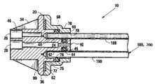
- FIG. 4is an elevational cross-sectional view of the connector shown in FIG. 1 .
- the disclosed connector 10is described herein according to its use with a vitrectomy console. However, those of ordinary skill in the art will understand its applicability to other ophthalmic surgical consoles as well as a variety of different types of other medical equipment, such as equipment used by dentists or veterinarians, or still other equipment requiring the use of multiple fluids in a procedure enabled by the medical equipment.
- the preferred embodiment of the connector 10 described hereinis used in connection with a system for performing a fluid/gas exchange during vitrectomy surgery.
- a preferred systemis described in more detail in U.S. application Ser. No. 11/855,198, filed Sep. 14, 2007, and entitled “Surgical Console”, which is commonly owned with the present invention and incorporated herein by reference.
- the disclosed connector 10is fabricated from ABS plastic, and further includes two O-rings 44 , 50 and an RFID tag 99 .
- the RFID tag 99is captured inside of a sonic welded two part assembly.
- the design of the disclosed connector 10delivers pressurized gas, either C 3 F 8 or SF 6 , through one internal passage and pressurized air through another internal passage.
- connector 10has a rear body portion 20 with a rear side 22 and a front side 24 .
- the rear side 22 of the rear body portion 20has an opening or port 26 for fluidly coupling with tubing for delivering pressurized air to one end of a consumable (i.e. syringe) used in a fluid/gas exchange, and an opening or port 28 for fluidly coupling with tubing for delivering pressurized gas (i.e. C 3 F 8 or SF 6 ) to an opposite end of such a consumable.
- a consumablei.e. syringe
- pressurized gasi.e. C 3 F 8 or SF 6
- opening 28 for the gas tubeis located substantially on the center line of the rear body portion 20
- opening 26 for the air tubeis formed substantially adjacent to the opening 28 .
- gussets 30extend inwardly from the shroud 32 and support the opening 28 for the gas tube.
- the opening 26 for the air tubeis formed as part of the shroud 32 .
- the shroud 32itself is supported by two gussets 34 extending from the flange portion 36 of the rear body portion 20 .
- an opening or port 40 for the pressurized gason the front side 24 of the rear body portion 20 is an opening or port 40 for the pressurized gas.
- This opening 40is located in a projection 42 extending from the front side 24 of the rear body portion 20 .
- an o-ring 44for fluidly sealing with a portion 188 of a manifold 189 of a vitrectomy console 200 .
- Portion 188is for delivering pressurized gas (i.e. C 3 F 8 or SF 6 ).
- a ring-shaped flange 25also extends from front side 24 of rear body portion 20 .
- a passage 46 for the pressurized airends in a substantially ring-shaped channel 48 defined by projection 42 and ring-shaped flange 25 .
- An o-ring 50is for fluidly sealing with a portion 190 of manifold 189 .
- Portion 190is for delivering pressurized air.
- a front body portion 60mating to the rear body portion 20 is a front body portion 60 .
- the front body portion 60includes a flange 62 which surrounds flange 25 of the rear body portion 20 . Captured between the front body portion 20 and the rear body portion 60 is a substantially ring-shaped RFID (radio frequency identification) tag 99 .
- a track engagement portion 66 and a slot 68are formed as part of the front body portion 60 to facilitate connection to portion 190 of manifold 189 .
- a shroud portion 70protects the projection 42 and o-ring seals 45 and 50 .
- the RFID tag 99fits within a recess 72 formed in the flange portion 62 of the front body portion 60 .
- the recess 72may also be formed in the flange portion 36 of the rear body portion 20 .
- front body portion 60 of connector 10is fluidly coupled to manifold 189 of vitrectomy console 200
- rear body portionis fluidly coupled to a consumable (i.e. syringe) for use in a fluid/gas exchange.
- pressurized gasi.e. C 3 F 8 or SF 6
- pressurized airfrom portion 188 of manifold 189 is delivered to opening 40 .
- Pressurized airfrom portion 190 of manifold 189 is delivered to ring-shaped channel 48 and passageway 46 .
- Pressurized gasis delivered to tubing 172 via opening 28 .
- tubing 172is fluidly sealed within opening 28 , and the other end of tubing 172 is fluidly coupled to a first end of a syringe used for performing the fluid/gas exchange. Pressurized air is delivered to tubing 182 via opening 26 .
- One end of tubing 182is fluidly sealed within opening 28 , and the other end of tubing 182 is fluidly coupled to the second end of the syringe.
- Tubing 172 and 182are preferably socket bonded within openings 28 and 26 , respectively, using an adhesive.
- Both the rear body portion 20 and the front body portion 60 of the disclosed connector 10are made of a moldable plastic suitable for use with medical equipment. Once molded, a first smaller o-ring 44 is mounted within a recess 45 formed in projection 42 . A second, larger o-ring 50 is inserted into a recess 76 formed by flange 25 and front body portion 60 . The RDIF tag 99 is then inserted into the recess 76 when front body portion 60 and the rear body portion 20 are pushed together in an interfitting relationship.
- the action of pushing the front body portion 20 and rear body portion 60 togetherdoes several things.
- contact of the RFID tag 99 with the flange 36 on the rear body portion 20holds the RFID tag 99 in place.
Landscapes
- Engineering & Computer Science (AREA)
- General Engineering & Computer Science (AREA)
- Mechanical Engineering (AREA)
- Health & Medical Sciences (AREA)
- Heart & Thoracic Surgery (AREA)
- Pulmonology (AREA)
- Anesthesiology (AREA)
- Biomedical Technology (AREA)
- Hematology (AREA)
- Life Sciences & Earth Sciences (AREA)
- Animal Behavior & Ethology (AREA)
- General Health & Medical Sciences (AREA)
- Public Health (AREA)
- Veterinary Medicine (AREA)
- Infusion, Injection, And Reservoir Apparatuses (AREA)
- External Artificial Organs (AREA)
Abstract
Description
This application claims the priority of U.S. Provisional Application Ser. No. 60/847,180 filed Sep. 26, 2006.
The present invention pertains to connectors used in lines for conducting fluid; more particularly the present invention pertains to a dual fluid connector.
In many different types of equipment, particularly medical equipment, multiple fluids are often used during medical procedures to treat patients. One example of such medical equipment is a vitrectomy system used for operations on the eye or eyes of a patient. In a fluid/gas exchange performed during a vitrectomy surgery, there is often a need for a source of pressurized retinal tamponading gases (i.e. C3F8and SF6) as well as a need for a source of pressurized air.
Prior art connectors used to handle multiple fluids have presented several problems. Such problems include difficulty coupling the large number of tubes that conduct the pressurized fluids between their respective sources and destinations. This large number of tubes also necessitates a connector having a relatively large size. Accordingly, a need remains in the art for a small, simple connector that enables better management and connection of tubing used for such fluids.
The present invention is a fluid connector that enables better management and connection of tubing used for medical or surgical fluids. The fluid connector has a rear body portion and a front body portion. The rear body portion has a rear side and a front side. The rear side has a center port and an off-center port, and the front side has a center projection with a center opening, a ring-shaped flange disposed around the center projection, and a ring-shaped channel defined by the center projection and the ring-shaped flange. The rear body portion also has a central passage extending through the rear body portion. The central passage originates at the center port and terminates at the center opening. The rear body portion also has an off-center passage extending through the rear body portion. The off-center passage originates at the off-center port and terminates at the ring-shaped channel. The front body portion is constructed and arranged for interfitment over the ring-shaped flange of the rear body portion and is for coupling with a manifold of a surgical console. The front body portion shrouds the center projection and further defines the ring-shaped channel.
A better understanding of the dual fluid connector of the present invention may be had by reference to the following drawing figures when read in conjunction with the following Description of the Embodiments.
The disclosedconnector 10 is described herein according to its use with a vitrectomy console. However, those of ordinary skill in the art will understand its applicability to other ophthalmic surgical consoles as well as a variety of different types of other medical equipment, such as equipment used by dentists or veterinarians, or still other equipment requiring the use of multiple fluids in a procedure enabled by the medical equipment.
The preferred embodiment of theconnector 10 described herein is used in connection with a system for performing a fluid/gas exchange during vitrectomy surgery. A preferred system is described in more detail in U.S. application Ser. No. 11/855,198, filed Sep. 14, 2007, and entitled “Surgical Console”, which is commonly owned with the present invention and incorporated herein by reference. The disclosedconnector 10 is fabricated from ABS plastic, and further includes two O-rings RFID tag 99. TheRFID tag 99 is captured inside of a sonic welded two part assembly. In use, the design of the disclosedconnector 10 delivers pressurized gas, either C3F8or SF6, through one internal passage and pressurized air through another internal passage.
As may be seen inFIG. 2 andFIG. 3A ,connector 10 has arear body portion 20 with arear side 22 and afront side 24. Therear side 22 of therear body portion 20 has an opening orport 26 for fluidly coupling with tubing for delivering pressurized air to one end of a consumable (i.e. syringe) used in a fluid/gas exchange, and an opening orport 28 for fluidly coupling with tubing for delivering pressurized gas (i.e. C3F8or SF6) to an opposite end of such a consumable. Bothopenings shroud 32. In the preferred embodiment, opening28 for the gas tube is located substantially on the center line of therear body portion 20, and opening26 for the air tube is formed substantially adjacent to the opening28. In the preferred embodiment,gussets 30 extend inwardly from theshroud 32 and support the opening28 for the gas tube. The opening26 for the air tube is formed as part of theshroud 32. Theshroud 32 itself is supported by twogussets 34 extending from theflange portion 36 of therear body portion 20.
As may be seen in the sectional view ofFIG. 4 , on thefront side 24 of therear body portion 20 is an opening orport 40 for the pressurized gas. This opening40 is located in aprojection 42 extending from thefront side 24 of therear body portion 20. Surrounding the opening40 is an o-ring 44 for fluidly sealing with aportion 188 of a manifold189 of a vitrectomy console200.Portion 188 is for delivering pressurized gas (i.e. C3F8or SF6). A ring-shaped flange 25 also extends fromfront side 24 ofrear body portion 20. Apassage 46 for the pressurized air ends in a substantially ring-shaped channel 48 defined byprojection 42 and ring-shaped flange 25. An o-ring 50 is for fluidly sealing with aportion 190 of manifold189.Portion 190 is for delivering pressurized air.
As shown inFIGS. 2 ,3B, and4, mating to therear body portion 20 is afront body portion 60. Thefront body portion 60 includes aflange 62 which surroundsflange 25 of therear body portion 20. Captured between thefront body portion 20 and therear body portion 60 is a substantially ring-shaped RFID (radio frequency identification)tag 99. Atrack engagement portion 66 and aslot 68 are formed as part of thefront body portion 60 to facilitate connection toportion 190 of manifold189. Ashroud portion 70 protects theprojection 42 and o-ring seals
Referring back toFIG. 4 , it may be seen that theRFID tag 99 fits within arecess 72 formed in theflange portion 62 of thefront body portion 60. Those of ordinary skill in the art will understand that therecess 72 may also be formed in theflange portion 36 of therear body portion 20.
In operation,front body portion 60 ofconnector 10 is fluidly coupled to manifold189 of vitrectomy console200, and rear body portion is fluidly coupled to a consumable (i.e. syringe) for use in a fluid/gas exchange. More specifically, pressurized gas (i.e. C3F8or SF6) fromportion 188 of manifold189 is delivered toopening 40. Pressurized air fromportion 190 of manifold189 is delivered to ring-shapedchannel 48 andpassageway 46. Pressurized gas is delivered totubing 172 viaopening 28. One end oftubing 172 is fluidly sealed withinopening 28, and the other end oftubing 172 is fluidly coupled to a first end of a syringe used for performing the fluid/gas exchange. Pressurized air is delivered totubing 182 viaopening 26. One end oftubing 182 is fluidly sealed withinopening 28, and the other end oftubing 182 is fluidly coupled to the second end of the syringe.Tubing openings
Both therear body portion 20 and thefront body portion 60 of the disclosedconnector 10 are made of a moldable plastic suitable for use with medical equipment. Once molded, a first smaller o-ring 44 is mounted within arecess 45 formed inprojection 42. A second, larger o-ring 50 is inserted into arecess 76 formed byflange 25 andfront body portion 60. TheRDIF tag 99 is then inserted into therecess 76 whenfront body portion 60 and therear body portion 20 are pushed together in an interfitting relationship.
The action of pushing thefront body portion 20 andrear body portion 60 together does several things. First, contact of theRFID tag 99 with theflange 36 on therear body portion 20 holds theRFID tag 99 in place. Second, when the outer surface of theprojection 42 on therear body portion 20 is slid into thelarger opening 78 in thefront body portion 60, aspace 76 is formed which captures and positions the second or larger o-ring 50. Third, theflange 36 on therear body portion 20 contacts theflange 62 on thefront body portion 60. This contact allows for sonic welding of theflange 36 to theflange 62. While sonic welding of therear body portion 20 to thefront body portion 60 is used in the preferred embodiment, those of ordinary skill in the art will understand that other attachment methods may be used such as adhesive, spin-bonding or heat without departing from the scope of the disclosed invention.
While the dual fluid connector of the present invention has been disclosed according to its preferred and alternate embodiments, those of ordinary skill in the art will understand that yet other embodiments have been enabled by the foregoing disclosure. Such other embodiments shall be included within the scope and meaning of the appended claims.
Claims (12)
1. A fluid connector, comprising:
a rear body portion having:
a rear side and a front side, the rear side having a center port and an off-center port, the front side having a center projection with a center opening and an annular groove for receiving an o-ring, a ring-shaped flange disposed around the center projection, and a ring-shaped channel defined by the center projection and the ring-shaped flange;
a central passage extending through the rear body portion, the central passage originating at the center port and terminating at the center opening;
an off-center passage extending through the rear body portion, the off-center passage originating at the off-center port and terminating at the ring-shaped channel;
a front body portion constructed and arranged for interfitment over the ring-shaped flange of the rear body portion and for coupling with a manifold of a surgical console, whereby the front body portion shrouds the center projection and further defines the ring-shaped channel;
the o-ring fluidly sealing with an interior surface of the manifold;
the ring-shaped flange and the front body portion defining a second annular groove for receiving a second o-ring; and
the second o-ring fluidly sealing with an exterior surface of the manifold.
2. The fluid connector ofclaim 1 wherein the manifold is for providing pressurized gas to the center opening and pressurized air to the ring-shaped channel.
3. The fluid connector ofclaim 2 wherein the pressurized gas is a retinal tamponading gas.
4. The fluid connector ofclaim 1 further comprising a radio frequency identification tag disposed within the connector.
5. The fluid connector ofclaim 1 further comprising:
a first tubing having a first end fluidly sealed within the center port; and
a second tubing having a first end fluidly sealed within the off-center port.
6. The fluid connector ofclaim 5 wherein:
the first end of the first tubing is socket bonded within the center port; and
the first end of the second tubing is socket bonded within the off-center port.
7. The fluid connector ofclaim 6 wherein the socket bonding is accomplished via an adhesive.
8. A fluid connector system, comprising:
a fluid connector having:
a rear body portion having:
a rear side and a front side, the rear side having a center port and an off-center port, the front side having a center projection with a center opening, a ring-shaped flange disposed around the center projection, and a ring-shaped channel defined by the center projection and the ring-shaped flange;
a central passage extending through the rear body portion, the central passage originating at the center port and terminating at the center opening;
an off-center passage extending through the rear body portion, the off-center passage originating at the off-center port and terminating at the ring-shaped channel; and
a front body portion constructed and arranged for interfitment over the ring-shaped flange of the rear body portion, whereby the front body portion shrouds the center projection and further defines the ring-shaped channel; and
a manifold disposed within a surgical console having:
a first portion fluidly sealed to the center projection for providing pressurized gas to the fluid connector; and
a second portion fluidly sealed to the rear body portion and the front body portion for providing pressurized air to the ring-shaped channel.
9. The fluid connector system ofclaim 8 wherein:
the center projection has an annular groove for receiving an o-ring, and
the o-ring fluidly seals with an interior surface of the first portion of the manifold.
10. The fluid connector system ofclaim 9 wherein:
the ring-shaped flange and the front body portion define a second annular groove for receiving a second o-ring, and
the second o-ring fluidly seals with an exterior surface of the second portion of the manifold.
11. The fluid connector system ofclaim 8 wherein the pressurized gas is a retinal tamponading gas.
12. The fluid connector system ofclaim 8 further comprising a radio frequency identification tag disposed within the connector.
Priority Applications (1)
| Application Number | Priority Date | Filing Date | Title |
|---|---|---|---|
| US11/829,228US7625014B2 (en) | 2006-09-26 | 2007-07-27 | Dual fluid connector |
Applications Claiming Priority (2)
| Application Number | Priority Date | Filing Date | Title |
|---|---|---|---|
| US84718006P | 2006-09-26 | 2006-09-26 | |
| US11/829,228US7625014B2 (en) | 2006-09-26 | 2007-07-27 | Dual fluid connector |
Publications (2)
| Publication Number | Publication Date |
|---|---|
| US20080073906A1 US20080073906A1 (en) | 2008-03-27 |
| US7625014B2true US7625014B2 (en) | 2009-12-01 |
Family
ID=39224136
Family Applications (1)
| Application Number | Title | Priority Date | Filing Date |
|---|---|---|---|
| US11/829,228Active2027-10-07US7625014B2 (en) | 2006-09-26 | 2007-07-27 | Dual fluid connector |
Country Status (1)
| Country | Link |
|---|---|
| US (1) | US7625014B2 (en) |
Cited By (3)
| Publication number | Priority date | Publication date | Assignee | Title |
|---|---|---|---|---|
| US20130015654A1 (en)* | 2011-07-11 | 2013-01-17 | Jeffrey Jay Gilham | Air-Tight Push-In and Pull-Out Connector System with Positive Latching |
| US9713503B2 (en) | 2013-12-04 | 2017-07-25 | Novartis Ag | Surgical utility connector |
| US10088083B2 (en) | 2014-08-14 | 2018-10-02 | Novartis Ag | Multi lumen co-radial pneumatic connector |
Families Citing this family (12)
| Publication number | Priority date | Publication date | Assignee | Title |
|---|---|---|---|---|
| US20060212037A1 (en)* | 2005-03-16 | 2006-09-21 | Alcon, Inc. | Pumping chamber for a liquefaction handpiece |
| US7758585B2 (en)* | 2005-03-16 | 2010-07-20 | Alcon, Inc. | Pumping chamber for a liquefaction handpiece |
| US20090032121A1 (en)* | 2007-07-31 | 2009-02-05 | Chon James Y | Check Valve |
| US7849875B2 (en)* | 2007-07-31 | 2010-12-14 | Alcon, Inc. | Check valve |
| US8291933B2 (en) | 2008-09-25 | 2012-10-23 | Novartis Ag | Spring-less check valve for a handpiece |
| MY177292A (en)* | 2012-03-07 | 2020-09-10 | Deka Products Lp | Infusion pump assembly |
| MX376285B (en)* | 2013-07-03 | 2025-03-07 | Deka Products Lp | FLUID CONNECTOR ASSEMBLY. |
| CN104089130A (en)* | 2014-07-04 | 2014-10-08 | 江苏文凤化纤集团有限公司 | Flange special for nylon spinning machine |
| US10690277B2 (en)* | 2017-03-16 | 2020-06-23 | Oetiker Ny, Inc. | Radio frequency identification smart inspection assurance cap |
| US11048994B2 (en)* | 2017-08-11 | 2021-06-29 | Norma U.S. Holding Llc | Fluid line connector and assembly with securement detection |
| US11306857B2 (en)* | 2017-08-11 | 2022-04-19 | Norma U.S. Holding Llc | Fluid line connector and assembly with securement detection |
| CA3151262A1 (en)* | 2019-10-30 | 2021-05-06 | Daryl ANACLETO | Dual port pneumatic connector |
Citations (23)
| Publication number | Priority date | Publication date | Assignee | Title |
|---|---|---|---|---|
| US515119A (en)* | 1894-02-20 | Vltrifled-fire-clay-sewer-pipe joint | ||
| US1389768A (en)* | 1919-05-09 | 1921-09-06 | Guyton And Cumfer Mfg Company | Flanged coupling for double-pipe conduits |
| US1481255A (en)* | 1920-07-15 | 1924-01-22 | Harry A Cumfer | Transporting conduit for viscous substances and process of making the same |
| US2860311A (en)* | 1956-04-16 | 1958-11-11 | Gen Electric | Wave guides |
| US3109671A (en)* | 1960-02-12 | 1963-11-05 | Standard Oil Co | Tube coupling for heat exchanger and the like |
| US3317221A (en)* | 1963-08-29 | 1967-05-02 | Birwelco Ltd | Pipe joints |
| US3469863A (en)* | 1967-04-05 | 1969-09-30 | Trico Products Corp | Fluid coupling assembly |
| US3948315A (en)* | 1974-08-13 | 1976-04-06 | Brown Fintube Company | Closure for heat exchanger |
| US4108476A (en)* | 1977-04-11 | 1978-08-22 | Krupp Walter H | Precompressed piping system for handling cryogenic fluid |
| US4328862A (en)* | 1978-02-13 | 1982-05-11 | Swisscal Holding S.A. | Tube bundle heat exchanger |
| US4732414A (en)* | 1986-11-18 | 1988-03-22 | Junio Inaba | Joint for coaxial pipe |
| JPH02150593A (en)* | 1988-11-30 | 1990-06-08 | Mitsubishi Plastics Ind Ltd | Intermediate drain joint for double layer pipe |
| US5088774A (en)* | 1990-05-07 | 1992-02-18 | Tylan General, Inc. | Coupling for interconnection of coaxial tubing |
| US5184850A (en)* | 1989-07-07 | 1993-02-09 | Georg Fischer Ag | Method of connecting pipes of plastics material of a double pipe system and a pipe connection made by the method |
| US5431641A (en)* | 1993-06-02 | 1995-07-11 | Dornier Medizintechnik Gmbh | Plug arrangement for connecting sterile and non-sterile apparatus |
| US5628532A (en)* | 1995-04-27 | 1997-05-13 | Handy & Harman Automotive Group, Inc. | Laminated fuel line and connector |
| US5655794A (en)* | 1995-11-02 | 1997-08-12 | Ingersoll-Rand Company | Pneumatic connector |
| US6533328B2 (en)* | 2000-02-24 | 2003-03-18 | Calsonic Kansei Corporation | Joint for duplex pipes |
| US6649829B2 (en) | 2001-05-21 | 2003-11-18 | Colder Products Company | Connector apparatus and method for connecting the same for controlling fluid dispensing |
| US20040051308A1 (en)* | 2002-08-20 | 2004-03-18 | Coates Gordon R. | Slurpie hose connection |
| US7052047B1 (en)* | 2002-03-21 | 2006-05-30 | Lockheed Martin Corporation | Detachable high-pressure flow path coupler |
| US20070241560A1 (en)* | 2006-04-18 | 2007-10-18 | Malone David S | Coaxial quick connector |
| US20080294144A1 (en)* | 2007-05-24 | 2008-11-27 | Giovanni Leo | Touch Sensing Catheter |
- 2007
- 2007-07-27USUS11/829,228patent/US7625014B2/enactiveActive
Patent Citations (25)
| Publication number | Priority date | Publication date | Assignee | Title |
|---|---|---|---|---|
| US515119A (en)* | 1894-02-20 | Vltrifled-fire-clay-sewer-pipe joint | ||
| US1389768A (en)* | 1919-05-09 | 1921-09-06 | Guyton And Cumfer Mfg Company | Flanged coupling for double-pipe conduits |
| US1481255A (en)* | 1920-07-15 | 1924-01-22 | Harry A Cumfer | Transporting conduit for viscous substances and process of making the same |
| US2860311A (en)* | 1956-04-16 | 1958-11-11 | Gen Electric | Wave guides |
| US3109671A (en)* | 1960-02-12 | 1963-11-05 | Standard Oil Co | Tube coupling for heat exchanger and the like |
| US3317221A (en)* | 1963-08-29 | 1967-05-02 | Birwelco Ltd | Pipe joints |
| US3469863A (en)* | 1967-04-05 | 1969-09-30 | Trico Products Corp | Fluid coupling assembly |
| US3948315A (en)* | 1974-08-13 | 1976-04-06 | Brown Fintube Company | Closure for heat exchanger |
| US4108476A (en)* | 1977-04-11 | 1978-08-22 | Krupp Walter H | Precompressed piping system for handling cryogenic fluid |
| US4328862A (en)* | 1978-02-13 | 1982-05-11 | Swisscal Holding S.A. | Tube bundle heat exchanger |
| US4732414A (en)* | 1986-11-18 | 1988-03-22 | Junio Inaba | Joint for coaxial pipe |
| JPH02150593A (en)* | 1988-11-30 | 1990-06-08 | Mitsubishi Plastics Ind Ltd | Intermediate drain joint for double layer pipe |
| US5184850A (en)* | 1989-07-07 | 1993-02-09 | Georg Fischer Ag | Method of connecting pipes of plastics material of a double pipe system and a pipe connection made by the method |
| US5088774A (en)* | 1990-05-07 | 1992-02-18 | Tylan General, Inc. | Coupling for interconnection of coaxial tubing |
| US5431641A (en)* | 1993-06-02 | 1995-07-11 | Dornier Medizintechnik Gmbh | Plug arrangement for connecting sterile and non-sterile apparatus |
| US5628532A (en)* | 1995-04-27 | 1997-05-13 | Handy & Harman Automotive Group, Inc. | Laminated fuel line and connector |
| US5655794A (en)* | 1995-11-02 | 1997-08-12 | Ingersoll-Rand Company | Pneumatic connector |
| US6533328B2 (en)* | 2000-02-24 | 2003-03-18 | Calsonic Kansei Corporation | Joint for duplex pipes |
| US6649829B2 (en) | 2001-05-21 | 2003-11-18 | Colder Products Company | Connector apparatus and method for connecting the same for controlling fluid dispensing |
| US6897374B2 (en) | 2001-05-21 | 2005-05-24 | Colder Products Company | Connector apparatus and method for connecting the same |
| US7052047B1 (en)* | 2002-03-21 | 2006-05-30 | Lockheed Martin Corporation | Detachable high-pressure flow path coupler |
| US20040051308A1 (en)* | 2002-08-20 | 2004-03-18 | Coates Gordon R. | Slurpie hose connection |
| US6866299B2 (en)* | 2002-08-20 | 2005-03-15 | Husky Corporation, A Missouri Corporation | Slurpie hose connection |
| US20070241560A1 (en)* | 2006-04-18 | 2007-10-18 | Malone David S | Coaxial quick connector |
| US20080294144A1 (en)* | 2007-05-24 | 2008-11-27 | Giovanni Leo | Touch Sensing Catheter |
Cited By (3)
| Publication number | Priority date | Publication date | Assignee | Title |
|---|---|---|---|---|
| US20130015654A1 (en)* | 2011-07-11 | 2013-01-17 | Jeffrey Jay Gilham | Air-Tight Push-In and Pull-Out Connector System with Positive Latching |
| US9713503B2 (en) | 2013-12-04 | 2017-07-25 | Novartis Ag | Surgical utility connector |
| US10088083B2 (en) | 2014-08-14 | 2018-10-02 | Novartis Ag | Multi lumen co-radial pneumatic connector |
Also Published As
| Publication number | Publication date |
|---|---|
| US20080073906A1 (en) | 2008-03-27 |
Similar Documents
| Publication | Publication Date | Title |
|---|---|---|
| US7625014B2 (en) | Dual fluid connector | |
| US10603449B2 (en) | High-flow luer lock connector for a luer lock connection | |
| CN101396255B (en) | Seal assembly for surgical access device | |
| JP6483619B2 (en) | Combiner for connecting a tube set to a trocar | |
| KR102710651B1 (en) | Multi-modal five lumen gas circulation system for use in endoscopic surgical procedures | |
| KR20190117813A (en) | Multi-lumen tube set for gas circulation system with single lumen gas sealed access port and single lumen valve sealed access port | |
| CN113017786B (en) | Conveying sheath pipe and conveying system | |
| US20100152685A1 (en) | Dual aspiration line fluidic cassette | |
| JP2015524297A5 (en) | ||
| CN103027654A (en) | Closure device for end opening | |
| US20050245898A1 (en) | Surgical handpiece with quick-connection for irrigation and aspiration tubes | |
| US9801532B2 (en) | Medical instrument | |
| WO2007015831A1 (en) | Extended locking luer connector | |
| KR20190082114A (en) | Sterilization tray | |
| US20160287770A1 (en) | Implantable connector assembly and method of communicating an element to an implantable device | |
| JP4528051B2 (en) | Endoscope | |
| US20220151468A1 (en) | Distal end cover for endoscope and endoscope apparatus | |
| CN107614053B (en) | Connector for hemostasis | |
| CN220914645U (en) | Connecting the system | |
| CN213077055U (en) | face mask combined oropharyngeal airway | |
| CN210170025U (en) | Laparoscope | |
| WO2024118944A1 (en) | Air/water connector to prevent water leaking |
Legal Events
| Date | Code | Title | Description |
|---|---|---|---|
| AS | Assignment | Owner name:ALCON, INC., SWITZERLAND Free format text:ASSIGNMENT OF ASSIGNORS INTEREST;ASSIGNOR:TURNER, DENIS P.;REEL/FRAME:019713/0135 Effective date:20070816 | |
| STCF | Information on status: patent grant | Free format text:PATENTED CASE | |
| AS | Assignment | Owner name:NOVARTIS AG, SWITZERLAND Free format text:MERGER;ASSIGNOR:ALCON, INC.;REEL/FRAME:026376/0076 Effective date:20110408 | |
| FPAY | Fee payment | Year of fee payment:4 | |
| FPAY | Fee payment | Year of fee payment:8 | |
| AS | Assignment | Owner name:ALCON INC., SWITZERLAND Free format text:CONFIRMATORY DEED OF ASSIGNMENT EFFECTIVE APRIL 8, 2019;ASSIGNOR:NOVARTIS AG;REEL/FRAME:051454/0788 Effective date:20191111 | |
| MAFP | Maintenance fee payment | Free format text:PAYMENT OF MAINTENANCE FEE, 12TH YEAR, LARGE ENTITY (ORIGINAL EVENT CODE: M1553); ENTITY STATUS OF PATENT OWNER: LARGE ENTITY Year of fee payment:12 |