US7623928B2 - Controlling a subject's susceptibility to a seizure - Google Patents
Controlling a subject's susceptibility to a seizureDownload PDFInfo
- Publication number
- US7623928B2 US7623928B2US11/743,607US74360707AUS7623928B2US 7623928 B2US7623928 B2US 7623928B2US 74360707 AUS74360707 AUS 74360707AUS 7623928 B2US7623928 B2US 7623928B2
- Authority
- US
- United States
- Prior art keywords
- control
- subject
- neural
- intracranial
- state
- Prior art date
- Legal status (The legal status is an assumption and is not a legal conclusion. Google has not performed a legal analysis and makes no representation as to the accuracy of the status listed.)
- Expired - Fee Related, expires
Links
- 230000001537neural effectEffects0.000claimsabstractdescription228
- 230000000926neurological effectEffects0.000claimsabstractdescription120
- 238000011282treatmentMethods0.000claimsabstractdescription48
- 230000004936stimulating effectEffects0.000claimsdescription184
- 230000000638stimulationEffects0.000claimsdescription105
- 238000000034methodMethods0.000claimsdescription88
- 206010010904ConvulsionDiseases0.000claimsdescription81
- 238000002560therapeutic procedureMethods0.000claimsdescription54
- 210000000578peripheral nerveAnatomy0.000claimsdescription49
- 230000002109interictal effectEffects0.000claimsdescription24
- 210000004556brainAnatomy0.000claimsdescription22
- 239000002243precursorSubstances0.000claimsdescription21
- 238000012545processingMethods0.000claimsdescription19
- 206010015037epilepsyDiseases0.000claimsdescription14
- 239000003814drugSubstances0.000claimsdescription13
- 229940079593drugDrugs0.000claimsdescription13
- 230000000977initiatory effectEffects0.000claimsdescription5
- 239000013043chemical agentSubstances0.000claimsdescription4
- 238000001816coolingMethods0.000claims2
- 206010073854Preictal stateDiseases0.000claims1
- 230000000694effectsEffects0.000abstractdescription69
- 239000002858neurotransmitter agentSubstances0.000abstractdescription65
- 210000000653nervous systemAnatomy0.000abstractdescription29
- 230000008904neural responseEffects0.000abstractdescription6
- 206010029306Neurological signs and symptomsDiseases0.000abstractdescription2
- 201000010099diseaseDiseases0.000description233
- 208000037265diseases, disorders, signs and symptomsDiseases0.000description233
- 238000007917intracranial administrationMethods0.000description212
- 238000000537electroencephalographyMethods0.000description132
- 238000010586diagramMethods0.000description131
- 238000002567electromyographyMethods0.000description118
- 210000003625skullAnatomy0.000description83
- 206010044565TremorDiseases0.000description80
- 230000006870functionEffects0.000description80
- 208000024891symptomDiseases0.000description65
- 238000012544monitoring processMethods0.000description62
- 230000004044responseEffects0.000description51
- 239000008186active pharmaceutical agentSubstances0.000description48
- 230000004007neuromodulationEffects0.000description44
- 230000005856abnormalityEffects0.000description42
- 238000013461designMethods0.000description40
- 210000001519tissueAnatomy0.000description40
- 230000001143conditioned effectEffects0.000description35
- 230000001953sensory effectEffects0.000description34
- 230000033001locomotionEffects0.000description31
- 208000012661DyskinesiaDiseases0.000description29
- 230000003595spectral effectEffects0.000description29
- 210000002569neuronAnatomy0.000description26
- 239000013598vectorSubstances0.000description26
- 230000006854communicationEffects0.000description25
- 238000004891communicationMethods0.000description25
- 230000001054cortical effectEffects0.000description23
- 238000006243chemical reactionMethods0.000description22
- 210000001905globus pallidusAnatomy0.000description22
- 238000003491arrayMethods0.000description21
- 230000008859changeEffects0.000description21
- 230000001133accelerationEffects0.000description20
- 230000008901benefitEffects0.000description18
- 238000012512characterization methodMethods0.000description18
- 210000003128headAnatomy0.000description18
- 238000002513implantationMethods0.000description18
- 230000033228biological regulationEffects0.000description17
- 230000003750conditioning effectEffects0.000description17
- 230000001105regulatory effectEffects0.000description17
- 230000036982action potentialEffects0.000description16
- 206010006100BradykinesiaDiseases0.000description14
- 208000006083HypokinesiaDiseases0.000description14
- 208000012902Nervous system diseaseDiseases0.000description14
- 210000004027cellAnatomy0.000description14
- 230000000971hippocampal effectEffects0.000description14
- 210000003205muscleAnatomy0.000description14
- 230000008569processEffects0.000description14
- 210000004761scalpAnatomy0.000description14
- 208000025966Neurological diseaseDiseases0.000description13
- 230000006399behaviorEffects0.000description13
- 230000008878couplingEffects0.000description13
- 238000010168coupling processMethods0.000description13
- 238000005859coupling reactionMethods0.000description13
- 208000018737Parkinson diseaseDiseases0.000description12
- 238000004364calculation methodMethods0.000description12
- 230000004907fluxEffects0.000description12
- 230000036541healthEffects0.000description12
- 230000003044adaptive effectEffects0.000description11
- 210000003710cerebral cortexAnatomy0.000description10
- 230000007423decreaseEffects0.000description10
- 238000001514detection methodMethods0.000description10
- 238000001914filtrationMethods0.000description10
- 230000002123temporal effectEffects0.000description10
- 210000001103thalamusAnatomy0.000description10
- 206010022520Intention tremorDiseases0.000description9
- 210000001320hippocampusAnatomy0.000description9
- 230000001965increasing effectEffects0.000description9
- 210000000278spinal cordAnatomy0.000description9
- 210000004281subthalamic nucleusAnatomy0.000description9
- 210000004885white matterAnatomy0.000description9
- 238000004146energy storageMethods0.000description8
- 230000003227neuromodulating effectEffects0.000description8
- 238000011002quantificationMethods0.000description8
- 230000000087stabilizing effectEffects0.000description8
- 230000002739subcortical effectEffects0.000description8
- 238000007920subcutaneous administrationMethods0.000description8
- 208000016285Movement diseaseDiseases0.000description7
- 206010071390Resting tremorDiseases0.000description7
- 238000005516engineering processMethods0.000description7
- 210000003414extremityAnatomy0.000description7
- 238000010304firingMethods0.000description7
- 238000005259measurementMethods0.000description7
- 230000004048modificationEffects0.000description7
- 238000012986modificationMethods0.000description7
- 210000005036nerveAnatomy0.000description7
- 230000003287optical effectEffects0.000description7
- 238000011277treatment modalityMethods0.000description7
- 230000009471actionEffects0.000description6
- 238000007792additionMethods0.000description6
- 238000013459approachMethods0.000description6
- 230000002146bilateral effectEffects0.000description6
- 230000002060circadianEffects0.000description6
- 230000001276controlling effectEffects0.000description6
- 238000012423maintenanceMethods0.000description6
- 238000007726management methodMethods0.000description6
- 239000000203mixtureSubstances0.000description6
- 230000008062neuronal firingEffects0.000description6
- 230000001314paroxysmal effectEffects0.000description6
- 239000002831pharmacologic agentSubstances0.000description6
- 230000029058respiratory gaseous exchangeEffects0.000description6
- 230000002459sustained effectEffects0.000description6
- 210000003478temporal lobeAnatomy0.000description6
- 210000005010torsoAnatomy0.000description6
- 230000001755vocal effectEffects0.000description6
- 230000021542voluntary musculoskeletal movementEffects0.000description6
- 238000002679ablationMethods0.000description5
- 230000002051biphasic effectEffects0.000description5
- 210000000988bone and boneAnatomy0.000description5
- 230000003247decreasing effectEffects0.000description5
- 210000000744eyelidAnatomy0.000description5
- 230000003447ipsilateral effectEffects0.000description5
- 210000000337motor cortexAnatomy0.000description5
- 230000036403neuro physiologyEffects0.000description5
- 238000005457optimizationMethods0.000description5
- 230000000144pharmacologic effectEffects0.000description5
- 230000002829reductive effectEffects0.000description5
- 238000005070samplingMethods0.000description5
- 210000003901trigeminal nerveAnatomy0.000description5
- 210000001186vagus nerveAnatomy0.000description5
- 208000020925Bipolar diseaseDiseases0.000description4
- 206010026749ManiaDiseases0.000description4
- 208000028017Psychotic diseaseDiseases0.000description4
- 230000003466anti-cipated effectEffects0.000description4
- 230000002490cerebral effectEffects0.000description4
- 238000009826distributionMethods0.000description4
- 239000000284extractSubstances0.000description4
- 230000003176fibrotic effectEffects0.000description4
- 230000006872improvementEffects0.000description4
- 210000000627locus coeruleusAnatomy0.000description4
- 239000000463materialSubstances0.000description4
- 239000011159matrix materialSubstances0.000description4
- 210000000196olfactory nerveAnatomy0.000description4
- 238000000059patterningMethods0.000description4
- 230000002688persistenceEffects0.000description4
- 230000000291postprandial effectEffects0.000description4
- 210000003523substantia nigraAnatomy0.000description4
- 208000019901Anxiety diseaseDiseases0.000description3
- 206010052804Drug toleranceDiseases0.000description3
- 210000001015abdomenAnatomy0.000description3
- 230000003321amplificationEffects0.000description3
- 230000036506anxietyEffects0.000description3
- 210000004227basal gangliaAnatomy0.000description3
- 230000004397blinkingEffects0.000description3
- 239000003990capacitorSubstances0.000description3
- 239000003795chemical substances by applicationSubstances0.000description3
- 230000001684chronic effectEffects0.000description3
- 210000003792cranial nerveAnatomy0.000description3
- 230000006378damageEffects0.000description3
- 238000011161developmentMethods0.000description3
- 230000018109developmental processEffects0.000description3
- 238000012377drug deliveryMethods0.000description3
- 230000009977dual effectEffects0.000description3
- 238000002695general anesthesiaMethods0.000description3
- 230000026781habituationEffects0.000description3
- 239000007943implantSubstances0.000description3
- 230000002427irreversible effectEffects0.000description3
- 210000003140lateral ventricleAnatomy0.000description3
- 210000004373mandibleAnatomy0.000description3
- 238000004519manufacturing processMethods0.000description3
- 230000001095motoneuron effectEffects0.000description3
- 238000003199nucleic acid amplification methodMethods0.000description3
- 210000005112optic tractAnatomy0.000description3
- 230000004421optic tractsEffects0.000description3
- 230000002265preventionEffects0.000description3
- 210000002637putamenAnatomy0.000description3
- 230000009467reductionEffects0.000description3
- 230000000241respiratory effectEffects0.000description3
- 230000004043responsivenessEffects0.000description3
- 230000001020rhythmical effectEffects0.000description3
- 210000004092somatosensory cortexAnatomy0.000description3
- 238000001356surgical procedureMethods0.000description3
- 238000012546transferMethods0.000description3
- 238000002054transplantationMethods0.000description3
- 208000020401Depressive diseaseDiseases0.000description2
- 239000004593EpoxySubstances0.000description2
- 206010016654FibrosisDiseases0.000description2
- 206010019233HeadachesDiseases0.000description2
- 206010033664Panic attackDiseases0.000description2
- RTAQQCXQSZGOHL-UHFFFAOYSA-NTitaniumChemical compound[Ti]RTAQQCXQSZGOHL-UHFFFAOYSA-N0.000description2
- 230000003190augmentative effectEffects0.000description2
- 108091008698baroreceptorsProteins0.000description2
- 230000009286beneficial effectEffects0.000description2
- 230000007175bidirectional communicationEffects0.000description2
- 230000005540biological transmissionEffects0.000description2
- 230000000903blocking effectEffects0.000description2
- 210000000133brain stemAnatomy0.000description2
- 210000005013brain tissueAnatomy0.000description2
- 230000009172burstingEffects0.000description2
- 239000002775capsuleSubstances0.000description2
- 210000003198cerebellar cortexAnatomy0.000description2
- 210000004720cerebrumAnatomy0.000description2
- ZPUCINDJVBIVPJ-LJISPDSOSA-NcocaineChemical compoundO([C@H]1C[C@@H]2CC[C@@H](N2C)[C@H]1C(=O)OC)C(=O)C1=CC=CC=C1ZPUCINDJVBIVPJ-LJISPDSOSA-N0.000description2
- 239000002537cosmeticSubstances0.000description2
- 238000012217deletionMethods0.000description2
- 230000037430deletionEffects0.000description2
- 238000005553drillingMethods0.000description2
- 238000002651drug therapyMethods0.000description2
- 239000007772electrode materialSubstances0.000description2
- 238000004070electrodepositionMethods0.000description2
- 230000005672electromagnetic fieldEffects0.000description2
- 230000001667episodic effectEffects0.000description2
- 230000004399eye closureEffects0.000description2
- 230000004761fibrosisEffects0.000description2
- 239000012530fluidSubstances0.000description2
- 230000005484gravityEffects0.000description2
- 230000004886head movementEffects0.000description2
- 231100000869headacheToxicity0.000description2
- 230000002401inhibitory effectEffects0.000description2
- 230000030214innervationEffects0.000description2
- 230000001788irregularEffects0.000description2
- 210000003141lower extremityAnatomy0.000description2
- 235000012054mealsNutrition0.000description2
- 230000007246mechanismEffects0.000description2
- 210000003739neckAnatomy0.000description2
- 238000010606normalizationMethods0.000description2
- 208000019906panic diseaseDiseases0.000description2
- 230000001936parietal effectEffects0.000description2
- 230000036470plasma concentrationEffects0.000description2
- BASFCYQUMIYNBI-UHFFFAOYSA-NplatinumChemical compound[Pt]BASFCYQUMIYNBI-UHFFFAOYSA-N0.000description2
- 230000002360prefrontal effectEffects0.000description2
- 210000001774pressoreceptorAnatomy0.000description2
- 239000000047productSubstances0.000description2
- 208000020016psychiatric diseaseDiseases0.000description2
- 210000002804pyramidal tractAnatomy0.000description2
- 230000011514reflexEffects0.000description2
- 230000035945sensitivityEffects0.000description2
- 238000001228spectrumMethods0.000description2
- 210000001032spinal nerveAnatomy0.000description2
- 239000010935stainless steelSubstances0.000description2
- 229910001220stainless steelInorganic materials0.000description2
- 208000005809status epilepticusDiseases0.000description2
- 239000000126substanceSubstances0.000description2
- 238000006467substitution reactionMethods0.000description2
- 230000001629suppressionEffects0.000description2
- 230000002889sympathetic effectEffects0.000description2
- 230000000542thalamic effectEffects0.000description2
- 230000001225therapeutic effectEffects0.000description2
- 239000010936titaniumSubstances0.000description2
- 230000001256tonic effectEffects0.000description2
- 230000007704transitionEffects0.000description2
- 238000002604ultrasonographyMethods0.000description2
- 210000001364upper extremityAnatomy0.000description2
- 230000002861ventricularEffects0.000description2
- 230000000007visual effectEffects0.000description2
- SNICXCGAKADSCV-JTQLQIEISA-N(-)-NicotineChemical compoundCN1CCC[C@H]1C1=CC=CN=C1SNICXCGAKADSCV-JTQLQIEISA-N0.000description1
- KRQUFUKTQHISJB-YYADALCUSA-N2-[(E)-N-[2-(4-chlorophenoxy)propoxy]-C-propylcarbonimidoyl]-3-hydroxy-5-(thian-3-yl)cyclohex-2-en-1-oneChemical compoundCCC\C(=N/OCC(C)OC1=CC=C(Cl)C=C1)C1=C(O)CC(CC1=O)C1CCCSC1KRQUFUKTQHISJB-YYADALCUSA-N0.000description1
- 206010003791AuraDiseases0.000description1
- LSHUIGIYBNJHEQ-UHFFFAOYSA-NC(CC1CCCC1)C1CCC1Chemical compoundC(CC1CCCC1)C1CCC1LSHUIGIYBNJHEQ-UHFFFAOYSA-N0.000description1
- OKTJSMMVPCPJKN-UHFFFAOYSA-NCarbonChemical compound[C]OKTJSMMVPCPJKN-UHFFFAOYSA-N0.000description1
- 206010061818Disease progressionDiseases0.000description1
- LFQSCWFLJHTTHZ-UHFFFAOYSA-NEthanolChemical compoundCCOLFQSCWFLJHTTHZ-UHFFFAOYSA-N0.000description1
- 229910001200FerrotitaniumInorganic materials0.000description1
- 241000282412HomoSpecies0.000description1
- 208000023105Huntington diseaseDiseases0.000description1
- 206010020772HypertensionDiseases0.000description1
- 206010020852HypertoniaDiseases0.000description1
- 208000001953HypotensionDiseases0.000description1
- 206010021639IncontinenceDiseases0.000description1
- 241001465754MetazoaSpecies0.000description1
- VVQNEPGJFQJSBK-UHFFFAOYSA-NMethyl methacrylateChemical compoundCOC(=O)C(C)=CVVQNEPGJFQJSBK-UHFFFAOYSA-N0.000description1
- 229940121948Muscarinic receptor antagonistDrugs0.000description1
- 208000002740Muscle RigidityDiseases0.000description1
- 206010033892ParaplegiaDiseases0.000description1
- 208000037656Respiratory SoundsDiseases0.000description1
- 208000005793Restless legs syndromeDiseases0.000description1
- 208000025865UlcerDiseases0.000description1
- 230000001594aberrant effectEffects0.000description1
- 230000002159abnormal effectEffects0.000description1
- 210000002187accessory nerveAnatomy0.000description1
- 230000003213activating effectEffects0.000description1
- 230000001154acute effectEffects0.000description1
- 230000002411adverseEffects0.000description1
- 239000000956alloySubstances0.000description1
- 229910045601alloyInorganic materials0.000description1
- 210000004727amygdalaAnatomy0.000description1
- 201000007201aphasiaDiseases0.000description1
- 230000003416augmentationEffects0.000description1
- 230000003376axonal effectEffects0.000description1
- 239000000560biocompatible materialSubstances0.000description1
- 230000015572biosynthetic processEffects0.000description1
- 208000030963borderline personality diseaseDiseases0.000description1
- 210000003461brachial plexusAnatomy0.000description1
- 244000309466calfSpecies0.000description1
- 229910052799carbonInorganic materials0.000description1
- 230000030833cell deathEffects0.000description1
- 230000001413cellular effectEffects0.000description1
- 210000003169central nervous systemAnatomy0.000description1
- 210000003591cerebellar nucleiAnatomy0.000description1
- 210000001638cerebellumAnatomy0.000description1
- 210000003037cerebral aqueductAnatomy0.000description1
- 210000004889cervical nerveAnatomy0.000description1
- 239000000812cholinergic antagonistSubstances0.000description1
- 210000003109clavicleAnatomy0.000description1
- 238000004140cleaningMethods0.000description1
- 229960003920cocaineDrugs0.000description1
- 230000001149cognitive effectEffects0.000description1
- 150000001875compoundsChemical class0.000description1
- 239000004020conductorSubstances0.000description1
- 238000007796conventional methodMethods0.000description1
- 210000000877corpus callosumAnatomy0.000description1
- 238000007428craniotomyMethods0.000description1
- 230000009849deactivationEffects0.000description1
- 230000003111delayed effectEffects0.000description1
- 230000001419dependent effectEffects0.000description1
- 230000005750disease progressionEffects0.000description1
- 238000006073displacement reactionMethods0.000description1
- 229940052760dopamine agonistsDrugs0.000description1
- 239000003136dopamine receptor stimulating agentSubstances0.000description1
- 230000005684electric fieldEffects0.000description1
- 238000005538encapsulationMethods0.000description1
- 230000007613environmental effectEffects0.000description1
- 210000002409epiglottisAnatomy0.000description1
- 238000011156evaluationMethods0.000description1
- 230000002964excitative effectEffects0.000description1
- 230000000193eyeblinkEffects0.000description1
- 230000004438eyesightEffects0.000description1
- 239000004744fabricSubstances0.000description1
- 238000005562fadingMethods0.000description1
- 210000000245forearmAnatomy0.000description1
- 210000004055fourth ventricleAnatomy0.000description1
- 210000005153frontal cortexAnatomy0.000description1
- 210000001652frontal lobeAnatomy0.000description1
- 230000005021gaitEffects0.000description1
- 238000002682general surgeryMethods0.000description1
- PCHJSUWPFVWCPO-UHFFFAOYSA-NgoldChemical compound[Au]PCHJSUWPFVWCPO-UHFFFAOYSA-N0.000description1
- 229910052737goldInorganic materials0.000description1
- 239000010931goldSubstances0.000description1
- 210000004326gyrus cinguliAnatomy0.000description1
- 238000010438heat treatmentMethods0.000description1
- 230000036543hypotensionEffects0.000description1
- 230000001771impaired effectEffects0.000description1
- 238000002847impedance measurementMethods0.000description1
- 230000001976improved effectEffects0.000description1
- 230000006698inductionEffects0.000description1
- 230000001939inductive effectEffects0.000description1
- 238000002347injectionMethods0.000description1
- 239000007924injectionSubstances0.000description1
- 238000003780insertionMethods0.000description1
- 230000037431insertionEffects0.000description1
- 230000010354integrationEffects0.000description1
- 210000002425internal capsuleAnatomy0.000description1
- 210000002946intralaminar thalamic nucleiAnatomy0.000description1
- 238000007918intramuscular administrationMethods0.000description1
- 210000001503jointAnatomy0.000description1
- 210000000867larynxAnatomy0.000description1
- 230000002045lasting effectEffects0.000description1
- 238000004900launderingMethods0.000description1
- 210000002414legAnatomy0.000description1
- 230000003902lesionEffects0.000description1
- 230000000670limiting effectEffects0.000description1
- 210000000088lipAnatomy0.000description1
- 238000002690local anesthesiaMethods0.000description1
- 230000004807localizationEffects0.000description1
- 230000007774longtermEffects0.000description1
- 238000002483medicationMethods0.000description1
- 230000002503metabolic effectEffects0.000description1
- 238000001690micro-dialysisMethods0.000description1
- 230000007659motor functionEffects0.000description1
- 201000003631narcolepsyDiseases0.000description1
- 210000001640nerve endingAnatomy0.000description1
- 230000004770neurodegenerationEffects0.000description1
- 208000015122neurodegenerative diseaseDiseases0.000description1
- 230000004751neurological system processEffects0.000description1
- 229960002715nicotineDrugs0.000description1
- SNICXCGAKADSCV-UHFFFAOYSA-NnicotineNatural productsCN1CCCC1C1=CC=CN=C1SNICXCGAKADSCV-UHFFFAOYSA-N0.000description1
- 210000000826nictitating membraneAnatomy0.000description1
- 230000035764nutritionEffects0.000description1
- 235000016709nutritionNutrition0.000description1
- 229940127240opiateDrugs0.000description1
- 238000011369optimal treatmentMethods0.000description1
- 230000002450orbitofrontal effectEffects0.000description1
- 210000000056organAnatomy0.000description1
- 230000036961partial effectEffects0.000description1
- 230000001575pathological effectEffects0.000description1
- 230000000149penetrating effectEffects0.000description1
- 230000035515penetrationEffects0.000description1
- 230000008447perceptionEffects0.000description1
- 230000000737periodic effectEffects0.000description1
- 230000002093peripheral effectEffects0.000description1
- 210000001428peripheral nervous systemAnatomy0.000description1
- 210000004345peroneal nerveAnatomy0.000description1
- 238000011458pharmacological treatmentMethods0.000description1
- 230000010363phase shiftEffects0.000description1
- 229920003023plasticPolymers0.000description1
- 229910052697platinumInorganic materials0.000description1
- HWLDNSXPUQTBOD-UHFFFAOYSA-Nplatinum-iridium alloyChemical group[Ir].[Pt]HWLDNSXPUQTBOD-UHFFFAOYSA-N0.000description1
- 229920000642polymerPolymers0.000description1
- 229920001296polysiloxanePolymers0.000description1
- 210000000976primary motor cortexAnatomy0.000description1
- 238000012913prioritisationMethods0.000description1
- 230000002250progressing effectEffects0.000description1
- 230000007115recruitmentEffects0.000description1
- 210000000463red nucleusAnatomy0.000description1
- 230000008439repair processEffects0.000description1
- 238000011160researchMethods0.000description1
- 230000000284resting effectEffects0.000description1
- 210000004189reticular formationAnatomy0.000description1
- 210000001525retinaAnatomy0.000description1
- 230000002441reversible effectEffects0.000description1
- 201000000980schizophreniaDiseases0.000description1
- 230000037152sensory functionEffects0.000description1
- 210000000697sensory organAnatomy0.000description1
- 238000007493shaping processMethods0.000description1
- 210000001154skull baseAnatomy0.000description1
- 210000004872soft tissueAnatomy0.000description1
- 210000001679solitary nucleusAnatomy0.000description1
- 210000000273spinal nerve rootAnatomy0.000description1
- 230000006641stabilisationEffects0.000description1
- 238000011105stabilizationMethods0.000description1
- 210000000701subdural spaceAnatomy0.000description1
- 239000013589supplementSubstances0.000description1
- 238000004381surface treatmentMethods0.000description1
- 230000004083survival effectEffects0.000description1
- 210000000331sympathetic gangliaAnatomy0.000description1
- 210000000211third ventricleAnatomy0.000description1
- 210000002972tibial nerveAnatomy0.000description1
- 230000000451tissue damageEffects0.000description1
- 231100000827tissue damageToxicity0.000description1
- 229910052719titaniumInorganic materials0.000description1
- 210000002105tongueAnatomy0.000description1
- 238000011491transcranial magnetic stimulationMethods0.000description1
- 230000036269ulcerationEffects0.000description1
- 210000001260vocal cordAnatomy0.000description1
- 230000002747voluntary effectEffects0.000description1
Images


Classifications
- A—HUMAN NECESSITIES
- A61—MEDICAL OR VETERINARY SCIENCE; HYGIENE
- A61B—DIAGNOSIS; SURGERY; IDENTIFICATION
- A61B5/00—Measuring for diagnostic purposes; Identification of persons
- A61B5/40—Detecting, measuring or recording for evaluating the nervous system
- A61B5/4076—Diagnosing or monitoring particular conditions of the nervous system
- A61B5/4094—Diagnosing or monitoring seizure diseases, e.g. epilepsy
- A—HUMAN NECESSITIES
- A61—MEDICAL OR VETERINARY SCIENCE; HYGIENE
- A61B—DIAGNOSIS; SURGERY; IDENTIFICATION
- A61B5/00—Measuring for diagnostic purposes; Identification of persons
- A61B5/08—Measuring devices for evaluating the respiratory organs
- A61B5/0816—Measuring devices for examining respiratory frequency
- A—HUMAN NECESSITIES
- A61—MEDICAL OR VETERINARY SCIENCE; HYGIENE
- A61B—DIAGNOSIS; SURGERY; IDENTIFICATION
- A61B5/00—Measuring for diagnostic purposes; Identification of persons
- A61B5/103—Measuring devices for testing the shape, pattern, colour, size or movement of the body or parts thereof, for diagnostic purposes
- A61B5/11—Measuring movement of the entire body or parts thereof, e.g. head or hand tremor or mobility of a limb
- A61B5/1101—Detecting tremor
- A—HUMAN NECESSITIES
- A61—MEDICAL OR VETERINARY SCIENCE; HYGIENE
- A61B—DIAGNOSIS; SURGERY; IDENTIFICATION
- A61B5/00—Measuring for diagnostic purposes; Identification of persons
- A61B5/24—Detecting, measuring or recording bioelectric or biomagnetic signals of the body or parts thereof
- A—HUMAN NECESSITIES
- A61—MEDICAL OR VETERINARY SCIENCE; HYGIENE
- A61B—DIAGNOSIS; SURGERY; IDENTIFICATION
- A61B5/00—Measuring for diagnostic purposes; Identification of persons
- A61B5/24—Detecting, measuring or recording bioelectric or biomagnetic signals of the body or parts thereof
- A61B5/316—Modalities, i.e. specific diagnostic methods
- A61B5/369—Electroencephalography [EEG]
- A—HUMAN NECESSITIES
- A61—MEDICAL OR VETERINARY SCIENCE; HYGIENE
- A61B—DIAGNOSIS; SURGERY; IDENTIFICATION
- A61B5/00—Measuring for diagnostic purposes; Identification of persons
- A61B5/24—Detecting, measuring or recording bioelectric or biomagnetic signals of the body or parts thereof
- A61B5/316—Modalities, i.e. specific diagnostic methods
- A61B5/389—Electromyography [EMG]
- A—HUMAN NECESSITIES
- A61—MEDICAL OR VETERINARY SCIENCE; HYGIENE
- A61B—DIAGNOSIS; SURGERY; IDENTIFICATION
- A61B5/00—Measuring for diagnostic purposes; Identification of persons
- A61B5/40—Detecting, measuring or recording for evaluating the nervous system
- A61B5/4076—Diagnosing or monitoring particular conditions of the nervous system
- A61B5/4082—Diagnosing or monitoring movement diseases, e.g. Parkinson, Huntington or Tourette
- A—HUMAN NECESSITIES
- A61—MEDICAL OR VETERINARY SCIENCE; HYGIENE
- A61B—DIAGNOSIS; SURGERY; IDENTIFICATION
- A61B5/00—Measuring for diagnostic purposes; Identification of persons
- A61B5/48—Other medical applications
- A61B5/4836—Diagnosis combined with treatment in closed-loop systems or methods
- A61B5/4839—Diagnosis combined with treatment in closed-loop systems or methods combined with drug delivery
- A—HUMAN NECESSITIES
- A61—MEDICAL OR VETERINARY SCIENCE; HYGIENE
- A61N—ELECTROTHERAPY; MAGNETOTHERAPY; RADIATION THERAPY; ULTRASOUND THERAPY
- A61N1/00—Electrotherapy; Circuits therefor
- A61N1/02—Details
- A61N1/04—Electrodes
- A61N1/05—Electrodes for implantation or insertion into the body, e.g. heart electrode
- A61N1/0526—Head electrodes
- A61N1/0529—Electrodes for brain stimulation
- A—HUMAN NECESSITIES
- A61—MEDICAL OR VETERINARY SCIENCE; HYGIENE
- A61N—ELECTROTHERAPY; MAGNETOTHERAPY; RADIATION THERAPY; ULTRASOUND THERAPY
- A61N1/00—Electrotherapy; Circuits therefor
- A61N1/18—Applying electric currents by contact electrodes
- A61N1/32—Applying electric currents by contact electrodes alternating or intermittent currents
- A61N1/36—Applying electric currents by contact electrodes alternating or intermittent currents for stimulation
- A61N1/3605—Implantable neurostimulators for stimulating central or peripheral nerve system
- A61N1/3606—Implantable neurostimulators for stimulating central or peripheral nerve system adapted for a particular treatment
- A61N1/36064—Epilepsy
- A—HUMAN NECESSITIES
- A61—MEDICAL OR VETERINARY SCIENCE; HYGIENE
- A61N—ELECTROTHERAPY; MAGNETOTHERAPY; RADIATION THERAPY; ULTRASOUND THERAPY
- A61N1/00—Electrotherapy; Circuits therefor
- A61N1/18—Applying electric currents by contact electrodes
- A61N1/32—Applying electric currents by contact electrodes alternating or intermittent currents
- A61N1/36—Applying electric currents by contact electrodes alternating or intermittent currents for stimulation
- A61N1/3605—Implantable neurostimulators for stimulating central or peripheral nerve system
- A61N1/3606—Implantable neurostimulators for stimulating central or peripheral nerve system adapted for a particular treatment
- A61N1/36067—Movement disorders, e.g. tremor or Parkinson disease
- A—HUMAN NECESSITIES
- A61—MEDICAL OR VETERINARY SCIENCE; HYGIENE
- A61N—ELECTROTHERAPY; MAGNETOTHERAPY; RADIATION THERAPY; ULTRASOUND THERAPY
- A61N1/00—Electrotherapy; Circuits therefor
- A61N1/18—Applying electric currents by contact electrodes
- A61N1/32—Applying electric currents by contact electrodes alternating or intermittent currents
- A61N1/36—Applying electric currents by contact electrodes alternating or intermittent currents for stimulation
- A61N1/3605—Implantable neurostimulators for stimulating central or peripheral nerve system
- A61N1/3606—Implantable neurostimulators for stimulating central or peripheral nerve system adapted for a particular treatment
- A61N1/36082—Cognitive or psychiatric applications, e.g. dementia or Alzheimer's disease
- A—HUMAN NECESSITIES
- A61—MEDICAL OR VETERINARY SCIENCE; HYGIENE
- A61N—ELECTROTHERAPY; MAGNETOTHERAPY; RADIATION THERAPY; ULTRASOUND THERAPY
- A61N1/00—Electrotherapy; Circuits therefor
- A61N1/18—Applying electric currents by contact electrodes
- A61N1/32—Applying electric currents by contact electrodes alternating or intermittent currents
- A61N1/36—Applying electric currents by contact electrodes alternating or intermittent currents for stimulation
- A61N1/3605—Implantable neurostimulators for stimulating central or peripheral nerve system
- A61N1/36128—Control systems
- A61N1/36135—Control systems using physiological parameters
- A61N1/36139—Control systems using physiological parameters with automatic adjustment
- A—HUMAN NECESSITIES
- A61—MEDICAL OR VETERINARY SCIENCE; HYGIENE
- A61N—ELECTROTHERAPY; MAGNETOTHERAPY; RADIATION THERAPY; ULTRASOUND THERAPY
- A61N1/00—Electrotherapy; Circuits therefor
- A61N1/18—Applying electric currents by contact electrodes
- A61N1/32—Applying electric currents by contact electrodes alternating or intermittent currents
- A61N1/36—Applying electric currents by contact electrodes alternating or intermittent currents for stimulation
- A61N1/372—Arrangements in connection with the implantation of stimulators
- A—HUMAN NECESSITIES
- A61—MEDICAL OR VETERINARY SCIENCE; HYGIENE
- A61B—DIAGNOSIS; SURGERY; IDENTIFICATION
- A61B5/00—Measuring for diagnostic purposes; Identification of persons
- A61B5/68—Arrangements of detecting, measuring or recording means, e.g. sensors, in relation to patient
- A61B5/6846—Arrangements of detecting, measuring or recording means, e.g. sensors, in relation to patient specially adapted to be brought in contact with an internal body part, i.e. invasive
- A61B5/6847—Arrangements of detecting, measuring or recording means, e.g. sensors, in relation to patient specially adapted to be brought in contact with an internal body part, i.e. invasive mounted on an invasive device
- A61B5/6852—Catheters
- A—HUMAN NECESSITIES
- A61—MEDICAL OR VETERINARY SCIENCE; HYGIENE
- A61B—DIAGNOSIS; SURGERY; IDENTIFICATION
- A61B5/00—Measuring for diagnostic purposes; Identification of persons
- A61B5/68—Arrangements of detecting, measuring or recording means, e.g. sensors, in relation to patient
- A61B5/6846—Arrangements of detecting, measuring or recording means, e.g. sensors, in relation to patient specially adapted to be brought in contact with an internal body part, i.e. invasive
- A61B5/6847—Arrangements of detecting, measuring or recording means, e.g. sensors, in relation to patient specially adapted to be brought in contact with an internal body part, i.e. invasive mounted on an invasive device
- A61B5/6864—Burr holes
- A—HUMAN NECESSITIES
- A61—MEDICAL OR VETERINARY SCIENCE; HYGIENE
- A61B—DIAGNOSIS; SURGERY; IDENTIFICATION
- A61B5/00—Measuring for diagnostic purposes; Identification of persons
- A61B5/68—Arrangements of detecting, measuring or recording means, e.g. sensors, in relation to patient
- A61B5/6846—Arrangements of detecting, measuring or recording means, e.g. sensors, in relation to patient specially adapted to be brought in contact with an internal body part, i.e. invasive
- A61B5/6867—Arrangements of detecting, measuring or recording means, e.g. sensors, in relation to patient specially adapted to be brought in contact with an internal body part, i.e. invasive specially adapted to be attached or implanted in a specific body part
- A61B5/6868—Brain
- A—HUMAN NECESSITIES
- A61—MEDICAL OR VETERINARY SCIENCE; HYGIENE
- A61B—DIAGNOSIS; SURGERY; IDENTIFICATION
- A61B5/00—Measuring for diagnostic purposes; Identification of persons
- A61B5/68—Arrangements of detecting, measuring or recording means, e.g. sensors, in relation to patient
- A61B5/6846—Arrangements of detecting, measuring or recording means, e.g. sensors, in relation to patient specially adapted to be brought in contact with an internal body part, i.e. invasive
- A61B5/6879—Means for maintaining contact with the body
- A61B5/6882—Anchoring means
- A—HUMAN NECESSITIES
- A61—MEDICAL OR VETERINARY SCIENCE; HYGIENE
- A61B—DIAGNOSIS; SURGERY; IDENTIFICATION
- A61B5/00—Measuring for diagnostic purposes; Identification of persons
- A61B5/72—Signal processing specially adapted for physiological signals or for diagnostic purposes
- A61B5/7203—Signal processing specially adapted for physiological signals or for diagnostic purposes for noise prevention, reduction or removal
- A—HUMAN NECESSITIES
- A61—MEDICAL OR VETERINARY SCIENCE; HYGIENE
- A61N—ELECTROTHERAPY; MAGNETOTHERAPY; RADIATION THERAPY; ULTRASOUND THERAPY
- A61N1/00—Electrotherapy; Circuits therefor
- A61N1/02—Details
- A61N1/04—Electrodes
- A61N1/05—Electrodes for implantation or insertion into the body, e.g. heart electrode
- A61N1/0526—Head electrodes
- A61N1/0529—Electrodes for brain stimulation
- A61N1/0531—Brain cortex electrodes
- A—HUMAN NECESSITIES
- A61—MEDICAL OR VETERINARY SCIENCE; HYGIENE
- A61N—ELECTROTHERAPY; MAGNETOTHERAPY; RADIATION THERAPY; ULTRASOUND THERAPY
- A61N1/00—Electrotherapy; Circuits therefor
- A61N1/02—Details
- A61N1/04—Electrodes
- A61N1/05—Electrodes for implantation or insertion into the body, e.g. heart electrode
- A61N1/0526—Head electrodes
- A61N1/0529—Electrodes for brain stimulation
- A61N1/0539—Anchoring of brain electrode systems, e.g. within burr hole
- A—HUMAN NECESSITIES
- A61—MEDICAL OR VETERINARY SCIENCE; HYGIENE
- A61N—ELECTROTHERAPY; MAGNETOTHERAPY; RADIATION THERAPY; ULTRASOUND THERAPY
- A61N1/00—Electrotherapy; Circuits therefor
- A61N1/18—Applying electric currents by contact electrodes
- A61N1/32—Applying electric currents by contact electrodes alternating or intermittent currents
- A61N1/36—Applying electric currents by contact electrodes alternating or intermittent currents for stimulation
- A61N1/3605—Implantable neurostimulators for stimulating central or peripheral nerve system
- A61N1/3606—Implantable neurostimulators for stimulating central or peripheral nerve system adapted for a particular treatment
- A61N1/36114—Cardiac control, e.g. by vagal stimulation
- A—HUMAN NECESSITIES
- A61—MEDICAL OR VETERINARY SCIENCE; HYGIENE
- A61N—ELECTROTHERAPY; MAGNETOTHERAPY; RADIATION THERAPY; ULTRASOUND THERAPY
- A61N1/00—Electrotherapy; Circuits therefor
- A61N1/18—Applying electric currents by contact electrodes
- A61N1/32—Applying electric currents by contact electrodes alternating or intermittent currents
- A61N1/36—Applying electric currents by contact electrodes alternating or intermittent currents for stimulation
- A61N1/372—Arrangements in connection with the implantation of stimulators
- A61N1/378—Electrical supply
- A61N1/3787—Electrical supply from an external energy source
Definitions
- the present inventionrelates generally to neurological disease and, more particularly, to intracranial stimulation for optimal control of movement disorders and other neurological disease.
- Treatment modalities for neurological diseaseincluding movement disorders such as Parkinson's disease, Huntington's disease, and Restless Leg Syndrome, as well as psychiatric disease including depression, bipolar disorder and borderline personality disorders.
- movement disorderssuch as Parkinson's disease, Huntington's disease, and Restless Leg Syndrome
- psychiatric diseaseincluding depression, bipolar disorder and borderline personality disorders.
- These treatment modalitiesare moderately efficacious; however, they suffer from several severe drawbacks.
- Each of these traditional treatment modalities and their associated limitationsare described below.
- One common conventional technique for controlling neurological diseaseincludes the use of dopaminergic agonists or anticholinergic agents. Medical management using these techniques requires considerable iteration in dosing adjustments before an “optimal” balance between efficacy and side effect minimization is achieved. Variation, including both circadian and postprandial variations, causes wide fluctuation in symptomatology. This commonly results in alternation between “on” and “off” periods during which the patient possesses and loses motor functionality, respectively.
- Tissue ablationis most commonly accomplished through stereotactic neurosurgical procedures, including pallidotomy, thalamotomy, subthalamotomy, and other lesioning procedures. These procedures have been found to be moderately efficacious. However, in addition to posing risks that are inherent to neurosurgical operations, these procedures suffer from a number of fundamental limitations. One such limitation is that tissue removal or destruction is irreversible. As a result, excessive or inadvertent removal of tissue cannot be remedied.
- tissue transplantationtypically from animal or human mesencephalic cells.
- tissue transplantation in humanshas been performed for many years, it remains experimental and is limited by ethical concerns when performed using a human source.
- graft survival, as well as subsequent functional connection with intracranial nucleiare problematic.
- the yield, or percentage of surviving cellsis relatively small and is not always predictable, posing difficulties with respect to the control of treatment “magnitude.”
- Another traditional approach for controlling neurological diseaseis the continuous electrical stimulation of a predetermined neurological region.
- Chronic high frequency intracranial electrical stimulationis typically used to inhibit cellular activity in an attempt to functionally replicate the effect of tissue ablation, such as pallidotomy and thalamotomy.
- Acute electrical stimulation and electrical recording and impedance measuring of neural tissuehave been used for several decades in the identification of brain structures for both research purposes as well as for target localization during neurosurgical operations for a variety of neurological diseases.
- reduction in tremorhas been achieved using frequencies typically on the order of 75 to 330 Hz.
- chronically implanted constant-amplitude electrical stimulatorshave been implanted in such sites as the thalamus, subthalamic nucleus and globus pallidus.
- Chronic constant-amplitude stimulationhas been shown to be moderately efficacious. However, it has also been found to be limited by the lack of responsiveness to change in patient system symptomatology and neuromotor function. Following implantation, a protracted phase of parameter adjustment, typically lasting several weeks to months, is endured by the patient while stimulation parameters are interactively adjusted during a series of patient appointments. Once determined, an “acceptable” treatment magnitude is maintained as a constant stimulation level.
- Stimulationis typically augmented with pharmacological treatment to accommodate such changes, causing fluctuation of the net magnitude of treatment with the plasma levels of the pharmacologic agent.
- a particularly significant drawback to the above and other traditional treatment modalitiesis that they suffer from inconsistencies in treatment magnitude.
- a decrease in responsiveness to pharmacologic agentseventually progresses to eventually preclude effective pharmacologic treatment.
- progression of diseaseoften necessitates reoperation to extend pallidotomy and thalamotomy lesion dimensions.
- tissue transplantationimbalances between cell transplant formation rates and cell death rates cause unanticipated fluctuations in treatment magnitude.
- changes in electrode position, electrode impedance, as well as patient responsiveness to stimulation and augmentative pharmacologic agentscause a change in response to a constant magnitude of therapy.
- magnetscommonly serve as input devices used by patients with implantable stimulators, including deep brain stimulators, pacemakers, and spinal cord stimulators.
- Current systemsrequire the patient to manually turn the system off at night time to conserve battery power and use such magnets to maintain system power. This presents considerable difficulty to many patients whose tremor significantly impairs arm function, as they are unable to hold a magnet in a stable manner over the implanted electronics module. Consequently, many patients are unable to turn their stimulators on in the morning without assistance.
- the apparatus and methodshould be responsive to unpredictable changes in symptomatology and minimize alternations between states of overtreatment and undertreatment.
- the systemshould also be capable of anticipating future changes in symptomatology and neuromotor functionality, and being responsive to such changes when they occur.
- One aspect of the inventionis a method of monitoring and storing EEG signals from a patient.
- the methodincludes monitoring EEG signals from a patient with an implanted unit, wirelessly transmitting a substantially real-time monitored EEG signal from the implanted unit to a communication module that is external to the patient's body, and storing the substantially-real time EEG signal in a memory that is external to the patient's body.
- the communication moduleis a portable patient interface module, and the memory is within the portable patient interface module.
- the communication modulemay also be a supervisory module that is used by a healthcare provider wherein the memory is within the supervisory module.
- the methodmay further comprise establishing a wireless communication link between the implanted unit and the communication module, where the monitoring and transmitting the EEG signal is performed substantially continuously while the wireless communication link is established between the implanted unit and the communication module. Storing the transmitted EEG signal may create a time history record of the EEG signal for a time period when the wireless communication link is established between the implanted unit and the communication module.
- the methodcan further comprise wirelessly transmitting a stored time history of the EEG signals that was previously stored in a memory of the implanted unit.
- wirelessly transmitting the monitored EEG signalfacilitates a real-time monitoring of the EEG signal with the communication module.
- the methodfurther comprises analyzing the EEG signal to estimate the patient's condition. Analyzing the EEG signal from the patient to estimate the patient's condition may include predicting future symptomatology of the patient's condition.
- the conditionmay comprise epilepsy and the future symptomatology may comprise a seizure.
- the embodimentmay further comprise initiating delivery of a therapy to the patient when the future symptomatology is predicted.
- the methodfurther comprises using the communication module to provide an output to the patient that is indicative of the patient's estimated condition.
- the conditioncan also comprise Parkinson's disease and the future symptomatology can comprise a tremor.
- the conditioncan also comprise depression or bipolar disorder.
- Another aspect of the inventionis a method of monitoring a patient's neurological or psychiatric condition.
- the methodincludes transmitting substantially real-time EEG signals that are sampled with an implanted device to an external device, and analyzing the substantially real-time EEG signals to estimate the patient's condition and/or predict future symptomatology of the patient's condition.
- the methodincludes facilitating delivery of a therapy to manage the patient's condition and/or predicted future symptomatology.
- the therapycan comprise at least one of electrical stimulation of a peripheral nerve, electrical stimulation of brain tissue, and drug delivery.
- the methodalso includes using the external device to provide an output to the patient that is indicative of the patient's estimated condition.
- transmittingis performed continuously during a time period in which there is a wireless communication link established between the implanted device and the external device.
- the patient's conditionis epilepsy and the future symptomatology comprises a seizure.
- the patient's conditioncan comprise Parkinson's disease and the future symptomatology can comprise a tremor.
- the patient's conditioncan also comprise depression or can comprise bipolar disorder.
- Another aspect of the inventionis a method of monitoring a patient's epilepsy condition.
- the methodincludes establishing a wireless communication link between an implanted device and a external device, sampling an EEG signal from a patient with the implanted device, continuously transmitting a substantially real-time EEG signal to the external device while the communication link is established, extracting parameters from the EEG signal to estimate the patient's epilepsy condition, wherein the parameters are indicative or predictive of a seizure, and providing a substantially real-time output to the patient with the external device that is indicative of the patient's epilepsy condition.
- the methodincludes initiating delivery of a therapy to manage the patient's epilepsy condition.
- the therapycomprises at least one of electrical stimulation of a peripheral nerve, electrical stimulation of brain tissue, and drug delivery.
- continuously transmittingis carried out using a wireless radiofrequency communication link.
- the methodalso includes storing the sampled EEG signal in a memory of the external device.
- FIG. 1is a schematic diagram of one embodiment of the present invention implanted bilaterally in a human patient.
- FIG. 2is an architectural block diagram of one embodiment of the neurological control system of the present invention.
- FIG. 3is a block diagram of one embodiment of an intracranial recording electrode (ICRE) signal processor and an intracranial stimulating electrode (ICSE) signal processor each of which are included within the signal processor illustrated in FIG. 2 .
- ICREintracranial recording electrode
- ICSEintracranial stimulating electrode
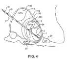
- FIG. 4is a schematic diagram of a globus pallidus implanted with stimulating and recording electrodes in accordance with one embodiment of the present invention.
- FIG. 5is a block diagram of one embodiment of an EMG signal processor that is included in one embodiment of the signal processor illustrated in FIG. 2 .
- FIG. 6is a block diagram of one embodiment of an EEG signal processor module that is included in one embodiment of the signal processor illustrated in FIG. 2 .
- FIG. 7is a block diagram of one embodiment of an accelerometer signal processor that is incorporated into certain embodiments of the signal processor illustrated in FIG. 2 .
- FIG. 8is a block diagram of one embodiment of an acoustic signal processor that is included in certain embodiments of the signal processor illustrated in FIG. 2 .
- FIG. 9is block diagram of one embodiment of a peripheral nerve electrode (PNE) signal processor 237 that is implemented in certain embodiments of signal processor 71 .
- PNE signalPNE signal
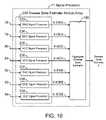
- FIG. 10is a schematic diagram of one embodiment of the signal processor illustrated in FIG. 2 .
- FIG. 11is a schematic diagram of the patient-neural modulator system illustrated in FIG. 2 illustrated to show its controller and observer components.
- FIG. 12is a schematic diagram of one embodiment of the control circuit illustrated in FIG. 2 .
- FIG. 13is a schematic diagram of electrical stimulation waveforms for neural modulation.
- FIG. 14is a schematic diagram of one example of the recorded waveforms.
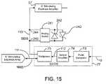
- FIG. 15is a schematic block diagram of an analog switch used to connect one or an opposing polarity pair of Zener diodes across the noninverting and inverting inputs of an intracranial recording electrode amplifier.
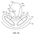
- FIG. 16is a diagram of a two coil embodiment of the power delivery unit.
- FIG. 17is a magnification of the configurations of FIGS. 16 and 18 showing the magnetic flux penetrating the skin.
- FIG. 18is a diagram of a three coil embodiment of the power delivery unit.
- FIG. 19is a diagram of the power delivery unit with coil holder.
- FIG. 20is a diagram of the coil holder.
- FIG. 21is a diagram of the electromagnetic copies in proximity to the head of a patient.
- FIG. 22is a diagram of multiple coil embodiments.
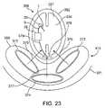
- FIG. 23is a diagram of the paracranial design, with implanted components in close proximity to the patient's head.
- FIG. 24is a diagram of the power conversion unit that includes the electromagnetic coupling element.
- FIG. 25is a diagram of the power conversion circuit.
- FIG. 26is a diagram of the overall system.
- FIG. 27is a diagram of the stimulating and recording unit.
- FIG. 28is a diagram of the system enclosure secured to the calvarium.
- FIG. 29is a diagram of a lower profile design.
- FIG. 30is a diagram of a lower profile design with the system enclosure partially recessed into the calvarium.
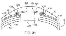
- FIG. 31is a diagram of a lower profile design with the system enclosure fully recessed into the calvarium.
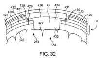
- FIG. 32is a diagram of a second lower profile design with the system enclosure fully recessed into the calvaium.
- FIG. 33is a diagram of a neurological control system.
- FIG. 34is a diagram of a second neurological control system.
- FIG. 35is a schematic diagram of one embodiment of the present invention implanted unilaterally in a human patient, with the system enclosure recessed in the calvarium, shown as a lateral view.
- FIG. 36is a schematic diagram of one embodiment of the present invention implanted unilaterally in a human patient, with the system enclosure recessed in the calvarium, shown as a anteroposterior view.
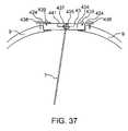
- FIG. 37is a schematic diagram of a cross section of calvarium with system enclosure shown implanted recessed within the calvarium.
- FIG. 38is a schematic diagram of a cross section of calvarium with drill bit shown in place after completion of process of drilling hole in calvarium.
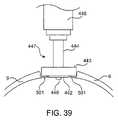
- FIG. 39is a schematic diagram of a cross section of calvarium with drill bit, with a penetration detection release mechanism, shown in place after completion of process of drilling hole in calvarium.
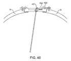
- FIG. 40is a diagram depicting the path of the intracranial catheter and its connection to the electrical elements.
- FIG. 41depicts one design for the system enclosure for implantation in the calvarium.
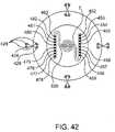
- FIGS. 42 and 43depict a dual intracranial catheter design.
- FIG. 44is a schematic diagram of one embodiment of the present invention implanted bilaterally in a human patient.
- FIG. 45is a schematic diagram, lateral view, of one embodiment of the present invention implanted unilaterally in a human patient.
- FIG. 46is a schematic diagram, anteroposterior view, of one embodiment of the present invention implanted unilaterally in a human patient, with multiple catheters and neuromodulators.
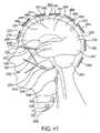
- FIG. 47is a schematic diagram of one embodiment of the present invention, depicting a set of noninvasive and implanted sensors and neuromodulators in a human patient.
- FIG. 48is a schematic diagram of the dermatomal distributions recruited by neuromodulators.
- FIG. 49is a schematic diagram of a noninvasive version of neurological control system, with sensors and neuromodulators overlying dermatomal distributions recruited by neuromodulators.
- FIG. 50is a functional block diagram of neurological control system, with sensors and neuromodulators implanted in the temporal lobe.
- FIG. 51is a functional block diagram of neurological control system, with sensors and neuromodulators implanted a multiplicity of locations, including the temporal lobe and deep brain regions.
- FIG. 52is a functional block diagram of neurological control system, with sensors and neuromodulators implanted a multiplicity of locations, including the temporal lobe and deep brain regions, showing control input and control output waveforms versus time.
- FIG. 53is a functional block diagram of neurological control system, with sensors and neuromodulators implanted a multiplicity of locations, including the temporal lobe and deep brain regions, showing control input and control output waveforms versus time.
- FIG. 54is a timing diagram showing control input and control output waveforms versus time along with five representative elements of neural state vector X over time, during which time control input deviates outside target range.
- FIG. 55is a timing diagram showing control input and control output waveforms versus time along with five representative elements of neural state vector X over time, during which time control input remains within target range.
- FIG. 56is a timing diagram showing control input and control output waveforms versus time along with five representative elements of neural state vector X over time, during which time control input remains within target range, under conditions with and without the application of a perturbation.
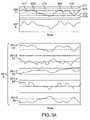
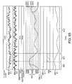
- FIG. 57is a timing diagram showing EEG waveforms, control input and control output waveforms versus time along with five representative elements of neural state vector X over time, during which time control input remains within target range, under conditions with and without the application of a perturbation.
- FIG. 58is a timing diagram showing EEG waveforms, control input and control output waveforms versus time along with one representative element of neural state vector X over time, during which time control input remains within normal range, under conditions without the application of a perturbation. Closed-loop neuromodulation control is turned on for a duration during which time control input is more tightly maintained in control range, a subset of normal range.
- FIG. 59is a timing diagram showing EEG waveforms, control input and control output waveforms versus time along with one representative element of neural state vector X over time, during which time control input deviates outside normal range into borderline range and into critical range, under conditions without the application of a perturbation. Closed-loop neuromodulation control remains off, and there are no EEG abnormalities nor neurological sings or symptoms.
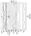
- FIG. 60is a timing diagram showing EEG waveforms, control input and control output waveforms versus time along with one representative element of neural state vector X over time, during which time control input deviates outside normal range into borderline range and into critical range, under conditions without the application of a perturbation. Closed-loop neuromodulation control remains off, and EEG abnormalities develop and are followed by neurological sings or symptoms.
- FIG. 61is a timing diagram showing EEG waveforms, control input and control output waveforms versus time along with one representative element of neural state vector X over time, during which time control input remains within normal range, under conditions without the application of a perturbation. Closed-loop neuromodulation control remains on, and there are no EEG abnormalities nor neurological sings or symptoms.
- FIG. 62is a timing diagram showing EEG waveforms, control input and control output waveforms versus time along with one representative element of neural state vector X over time, during which time control input deviates outside normal range and closed-loop neuromodulation control is turned on, bringing control input back into control range, which is a subset of normal range. There are no EEG abnormalities nor neurological sings or symptoms during this time.
- FIG. 63is a timing diagram showing EEG waveforms, control input and control output waveforms versus time along with one representative element of neural state vector X over time, during which time control input deviates outside normal range and closed-loop neuromodulation control is turned on, bringing control input back into control range, which is a subset of normal range, following which time closed-loop neuromodulation control is turned back off. There are no EEG abnormalities nor neurological sings or symptoms during this time.
- FIG. 64is a timing diagram showing EEG waveforms, control input and control output waveforms versus time along with one representative element of neural state vector X over time, during which time a perturbation is applied and control input decreases but remains inside normal range. Closed-loop neuromodulation control remains off, and there are no EEG abnormalities nor neurological sings or symptoms during this time.
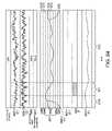
- FIG. 65is a timing diagram showing EEG waveforms, control input and control output waveforms versus time along with one representative element of neural state vector X over time, during which time a perturbation is applied and control input deviates outside normal range into borderline range and critical range and then returns spontaneously to normal range. Closed-loop neuromodulation control remains off, and there are no EEG abnormalities nor neurological sings or symptoms during this time.
- FIG. 66is a timing diagram showing EEG waveforms, control input and control output waveforms versus time along with one representative element of neural state vector X over time, during which time a perturbation is applied and control input deviates outside normal range into borderline range and critical range, then back into borderline range and normal range and again into borderline range and critical range, following which EEG abnormalities develop and which are followed by neurological sings or symptoms. Closed-loop neuromodulation control remains off during this time.
- FIG. 67is a timing diagram showing EEG waveforms, control input and control output waveforms versus time along with one representative element of neural state vector X over time, during which time a perturbation is applied and control input decreases but remains inside control range, which is a subset of normal range. Closed-loop neuromodulation control remains on, and there are no EEG abnormalities nor neurological sings or symptoms during this time.
- FIG. 68is a timing diagram showing EEG waveforms, control input and control output waveforms versus time along with one representative element of neural state vector X over time, during which time a perturbation is applied and control input deviates outside control range yet remains within normal range. Closed-loop neuromodulation control is turned on, and control input is brought back within control range. Control input remains within normal range and there are no EEG abnormalities nor neurological signs or symptoms during this time.
- FIG. 1is a schematic diagram of one embodiment of the intracranial stimulator of the present invention implanted bilaterally in a human patient.
- two neurological control systems 999are shown implanted bilaterally.
- Each system 999includes a stimulating and recording unit 26 and one or more intracranial components described below.
- the intracranial componentspreferably include a stimulating electrode array 37 .
- the stimulating electrodesmay also be extracranial; that is, attached to a peripheral nerve in addition to or in place of being located within the cranium.
- stimulating and recording unit 26 of each neurological control system 999is preferably implanted contralateral to the intracranial components of the device.
- the configuration illustrated in FIG. 1is just one example of the present invention. Many other configurations are contemplated.
- the stimulating and recording unit 26is implanted ipsilateral or bilateral to the intracranial components. It should also be understood that the stimulating and recording unit 26 can receive ipsilateral, contralateral or bilateral inputs from sensors and deliver ipsilateral, contralateral, or bilateral outputs to a single or a plurality of intracranial stimulating electrode arrays 37 .
- these inputsare direct or preamplified signals from at least one of EMG electrode array 50 , EEG electrode array 51 , Accelerometer Array 52 , Acoustic Transducer Array 53 , Peripheral Nerve Electrode Array 54 , and Intracranial Recording Electrode Array 38 .
- the signals input from these sensorswill be referred to herein as “sensory input modalities” 247 .
- the outputsinclude but are not limited to one or more stimulating current signals or stimulating voltage signals to Intracranial Stimulating Electrode Array 37 .
- the two unilateral systems 26are shown to receive sensory inputs from the side contralateral as well as the intracranial stimulating electrode arrays 37 .
- systems 26also receive sensory inputs from intracranial recording electrode arrays 38 .
- intracranial recording electrode arrays 38may provide valuable feedback information.
- stimulating and recording units 26may be a single device, two communicating devices, or two independent devices. Accordingly, these and other configurations are considered to be within the scope of the present invention. It is anticipated that stimulating and recording units 26 , if implemented as distinct units, would likely be implanted in separate procedures (soon after clinical introduction) to minimize the likelihood of drastic neurological complications.
- the intracranial stimulating electrode array 37includes a plurality of intracranial stimulating electrodes 1 , 2 , 3 and 4 .
- Array 37may, of course, have more or fewer electrodes than that depicted in FIG. 1 .
- These intracranial stimulating electrodes 1 - 4may be used to provide stimulation to a predetermined nervous system component.
- the electrical stimulation provided by the intracranial stimulating electrodes 1 - 4may be excitatory or inhibitory, and this may vary in a manner which is preprogrammed, varied in real-time, computed in advance using a predictive algorithm, or determined using another technique now or latter developed.
- the intracranial recording electrode arrays 38includes intracranial recording electrodes 5 and 6 .
- the intracranial recording electrodes 5 , 6are used to record cortical activity as a measure of response to treatment and as a predictor of impeding treatment magnitude requirements.
- intracranial recording electrodes 5 and 6are depicted in a location superficial to the intracranial stimulating electrodes 1 - 4 . However, this positioning may be reversed or the intracranial stimulating electrodes 1 - 4 and intracranial recording electrodes 5 and 6 may be interspersed in alternative embodiments.
- these electrodesmay be placed in at least one of motor cortex, premotor cortex, supplementary motor cortex, other motor cortical areas, somatosensory cortex, other sensory cortical areas, Wemicke's area, Broca's area, other cortical region, other intracranial region, and other extracranial region.
- an intracranial catheter 7is provided to mechanically support and facilitate electrical connection between intracranial and extracranial structures.
- intracranial catheter 7contains one or more wires connecting extracranial stimulating and recording circuit 26 to the intracranial electrodes, including but not limited to, intracranial stimulating electrodes 1 - 4 and intracranial recording electrodes 5 , 6 .
- the wires contained within intracranial catheter 7transmit stimulating electrode output signal (SEOS) to intracranial stimulating electrode array 37 .
- Such wiresadditionally transmit stimulating electrode input signal (SEIS) and recording electrode input signal (REIS), from intracranial stimulating electrode array 37 and intracranial recording electrode array 38 respectively, to stimulating and recording circuit 26 .
- SEOSstimulating electrode output signal
- SEISstimulating electrode input signal
- REISrecording electrode input signal
- Stimulating and recording circuit 26is protected within a circuit enclosure 44 .
- Circuit enclosure 44 and contained components, including stimulating and recording circuit 26comprise stimulating and recording unit 43 .
- stimulating and recording circuit 26can be placed extra cranially in a subclavian pocket as shown in FIG. 1 , or it may be placed in other extracranial or intracranial locations.
- Connecting cable 8generally provides electrical connection between intracranial or intracranial locations.
- a set of electrical wiresprovides the means for communication between the intracranial and extracranial components; however, it should be understood that alternate systems and techniques such as radiofrequency links, optical (including infrared) links with transcranial optical windows, magnetic links, and electrical links using the body components as conductors, may be used without departing from the present invention.
- connecting cable 8provides electrical connection between intracranial components 246 and stimulating and recording circuit 26 . In embodiments wherein stimulating and recording circuit 26 has an intracranial location, connecting cable 8 would likely be entirely intracranial.
- connecting cable 8may be confined entirely to subcutaneous region under the scalp 10 .
- a catheter anchor 29provides mechanical connection between intracranial catheter 7 and caldarium 9 .
- Catheter anchor 29is preferably deep to the overlying scalp 10 .
- Such a subcutaneous connecting cable 8provides electrical connection between intracranial electrodes 246 and stimulating and recording circuit 26 . Cable 8 may also connect any other sensors, including but not limited to any of sensory input modalities 247 , or other stimulating electrodes, medication dispensers, or actuators with stimulating and recording circuit 26 .
- Sensory feedbackis provided to recording and stimulating unit 26 from a multiplicity of sensors, collectively referred to as sensory input modalities 247 .
- Intracranial recording electrode array 38previously described, is intracranial in location. Additional sensors, most of which are located extracranially in the preferred embodiment, comprise the remainder of sensory input modalities 247 .
- Sensory input modalities 247provide information to stimulating and recording unit 26 . As will be described in greater detail below, such information is processed by stimulating and recording unit 26 to deduce the disease state and progression and its response to therapy.
- a head-mounted acoustic sensor 11is used to monitor any number of vibratory characteristics such as high frequency head vibration, muscle vibration, and/or speech production.
- Head-mounted acoustic sensor 11is connected to stimulating and recording circuit 26 with an acoustic sensor connecting cable 30 .
- a head-mounted accelerometer 12is implemented in certain embodiments of the present invention to monitor head movement and position with respect to gravity.
- Head-mounted accelerometer 12may be mounted to any structure or structures that enables it to accurately sense a desired movement. Such structures include, for example, the skull base, caldarium, clavicle, mandible, extraocular structures, soft tissues and vertebrae.
- Head-mounted accelerometer 12is connected to stimulating and recording circuit 26 with an accelerometer connecting cable 31 .
- a proximal electromyography (EMG) electrode array 45is also included in certain preferred embodiments of the invention.
- Proximal EMG electrode array 45includes a positive proximal EMG electrode 13 , a reference proximal EMG electrode 14 , and a negative proximal EMG electrode 15 .
- proximal EMG electrode array 45may include any number of type of electrodes.
- Proximal EMG electrode array 45is implanted in or adjacent to muscle tissue. In the embodiment illustrated in FIG. 1 , proximal EMG electrode array 45 is shown implanted within the neck of the human patient. However, it should be understood that this location is illustrative only and that proximal EMG electrode array 45 may be implanted in or adjacent to any muscle without departing from the spirit of the present invention.
- a proximal acoustic sensor 27may also be implemented in the present invention.
- Proximal acoustic sensor 27senses muscle vibration and may be used to augment, supplement or replace EMG recording.
- a proximal accelerometer 28may be used to sense movement, including tremor and voluntary activity, and orientation with respect to gravity.
- Proximal connecting cable 16provides electrical connection from the proximal EMG electrodes 14 and 15 , proximal acoustic sensor 27 , and proximal accelerometer 28 to stimulating and recording circuit 26 . In the illustrative embodiment, these sensors are shown connected to a common proximal connecting cable 16 .
- this configurationmay include the use of multiple connecting cables or implement other types of communication media without departing from the present invention. It should also be understood from the preceding description that the number of each type of sensor may also be increased or decreased, some sensor types may be eliminated, and other sensor types may be included without departing from the spirit of the present invention.
- a distal EMG electrode array 47may also be included in certain embodiments of the present invention.
- distal EMG electrode array 47typically includes a positive distal EMG electrode 17 , a reference distal EMG electrode 42 , and a negative distal EMG electrode 18 .
- Positive distal EMG electrode 17is connected to stimulating and recording circuit 26 by positive distal EMG connecting cable 20 .
- Negative distal EMG electrode 18is connected to stimulating and recording circuit 26 by negative distal EMG connecting cable 21 .
- Reference distal EMG electrode 42is connected to stimulating and recording circuit 26 by reference distal EMG connecting cable 48 .
- a distal acoustic sensor 19is connected to stimulating and recording circuit 26 by distal acoustic connecting cable 22 .
- Distal accelerometer 33is connected to stimulating and recording circuit 26 by distal accelerometer connecting cable 34 .
- Distal accelerometer 33is connected to stimulating and recording circuit 26 by distal accelerometer connecting cable 34 .
- distal EMG electrode array 47In the embodiment illustrated in FIG. 1 , distal EMG electrode array 47 , distal acoustic sensor 19 , and distal accelerometer 33 are shown located in the shoulder region. However, the distal EMG electrode array 47 may be located in other locations, including, for example, the masseter, temporalis, sternocleidomastoid, other portion of the head and neck, pectoralis, torso, abdomen, upper extremities, lower extremities, and other locations. The number of each type of sensor may be increased or decreased, some sensor types may be eliminated, and other sensor types may be included without departing from the spirit of the present invention.
- Enclosure-mounted EMG electrode array 46includes enclosure-mounted positive EMG electrode 23 , enclosure-mounted negative EMG electrode 24 and enclosure-mounted reference EMG electrode 25 , all of which are attached to the circuit enclosure 44 that encloses stimulating and recording unit 26 .
- the circuit enclosure 44is preferably included to provide robustness against potential lead entanglement and fracture.
- circuit enclosure 44is constructed of titanium and epoxy, or other single or combination of bio-compatible materials.
- Enclosure-mounted acoustic sensor 35 and enclosure-mounted accelerometer 36are mounted to stimulating and recording unit 43 . The number of each type of sensor may be increased or decreased, their locations changed, some sensor types eliminated, and other sensor types included without departing from the spirit of the present invention.
- EEG electrodes 39 , 40 , 41are provided.
- the EEG electrodesmay be mounted directly to connecting cable 8 or may be connected via intermediate cables. Any one of the numerous standard and new electrode configurations, or montages, may be employed in EEG electrodes 39 - 41 without departing from the present invention.
- a proximal peripheral nerve electrode array 98is connected to stimulating and recording circuit 26 by proximal peripheral nerve electrode array connecting cable 100 .
- Proximal peripheral nerve electrode array 98is shown located in the neck region. In this location proximal peripheral nerve electrode array 98 can interface with the vagus nerve, spinal accessory nerve, or nerve arising from cervical roots.
- a distal peripheral nerve electrode array 99is connected to stimulating and recording circuit 26 by distal peripheral nerve electrode array connecting cable 32 .
- Distal peripheral nerve electrode array 99is shown located by the proximal arm, in position to interface with the brachial plexus or proximal arm nerve.
- One or more of these peripheral nerve electrode arraysmay be implanted in these or other locations, including but not limited to the head, cranial nerves, neck, torso, abdomen, upper extremities, and lower extremities, without departing from the present invention.
- the peripheral nerve electrode arraysare each comprised of three epineural platinum-iridium ring electrodes, each in with an internal diameter approximately 30% larger than that of the epineurium, longitudinally spaced along the nerve. Electrodes of differing dimensions and geometries and constructed from different materials may alternatively be used without departing from the present invention.
- Alternative electrode configurationsinclude but are not limited to epineural, intrafascicular, or other intraneural electrodes; and materials include but are not limited to platinum, gold, stainless steel, carbon, and other element or alloy.
- FIG. 2is an architectural block diagram of one embodiment of the neurological control system 999 of the present invention for modulating the activity of at least one nervous system component in a patient.
- a nervous system componentincludes any component or structure comprising an entirety or portion of the nervous system, or any structure interfaced thereto.
- the nervous system component that is controlled by the present inventionincludes the globus pallidus internus.
- the controlled nervous system componentis the subthalamic nucleus.
- the neurological control system 999includes one or more implantable components 249 including a plurality of sensors each configured to sense a particular characteristic indicative of a neurological or psychiatric condition.
- One or more intracranial (IC) stimulating electrodes in an IC stimulating electrode array 37delivers a neural modulation signal to the same or other nervous system component as that being monitored by the system 26 .
- One or more sensors 38 , 51 , 52 , 53 , and 54sense the occurrence of neural responses to the neural modulation signals.
- Stimulating and recording unit 26generates the neural modulation signal based on the neural response sensed by the sensors.
- the neurological control system 999preferably also includes a patient interface module 55 and a supervisory module 56 .
- a control circuit 72(described below) is communicably coupled to the patient interface module 55 and receives signal inputs from and provides signal outputs to patient interface module 55 and supervisory module 56 .
- patient interface module 55 and supervisory module 56remain external to the body of the patient. However either of these devices may be connected via percutaneous leads or be partially or totally implanted without departing from the present invention.
- Patient interface module 55 and supervisory module 56facilitate adjustment of control parameters, monitoring of disease state, monitoring of response to therapy, monitoring of stimulating and recording circuit 26 , monitoring of impedance and other characteristics of intracranial stimulating electrode array 37 , monitoring of physiologic parameters, monitoring of vital signs, monitoring of any other characteristic or function of components of the present invention, including but not limited to the stimulating and recording circuit 26 , stimulating and recording unit 43 , circuit enclosure 44 , EMG electrode array 50 , EEG electrode array 51 , accelerometer array 52 , acoustic transducer array 53 , peripheral nerve electrode array 54 , and intracranial recording electrode array 38 .
- Such monitoring and adjustmentis accomplished through the use of any well known bi-directional communication between control circuit 72 and supervisory module 56 .
- a radio frequency linkis employed.
- other communication technologiesincluding but not limited to optical, percutaneous, or electromagnetic, may be used.
- patient interface module 55 and supervisory module 56are placed adjacent to the patients garments overlying the implanted stimulating and recording unit 43 .
- a communications handshaking protocolis executed.
- Communication handshaking routinesare known to those or ordinary skill in the art, and they enable establishment of a communication rate and protocol and facilitate mutual identification of devices.
- Patient interface module 55automatically downloads parameters from stimulating and recording circuit 26 and stores values of such parameters in a memory. When the transfer of these parameter values is complete, patient interface module 55 emits a audible signal such as a series of beeps, and the patient turns off patient interface module 55 and removes it from its position overlying the implanted stimulating and recording unit 43 .
- Parameter valuesmay then be retrieved by the patient by a routine including but not limited to a menu driven interface, and the values may be transmitted via telephone conversation or other communication method to a health care professional.
- Supervisory module 56operates in the same manner with one addition; a step is provided during which the health care professional may upload parameters to stimulating and recording circuit 26 to alter its function including by means of changing parameters including but not limited to control laws gains and thresholds, filter parameters, signal processing parameters, stimulation waveform modes (including at least one of current regulated, voltage regulated, frequency regulated, or pulse width regulated), and stimulation waveform parameters.
- Control lawsare defined by a set of parameters specific to the particular control law. Common parameters include preset gains, threshold levels, saturation amplitudes, sampling rates, and others. Adaptive controllers change in response to the behavior of the system being controlled; as such, in addition to preset parameters, adaptive controllers possess a set of varying parameters. These varying parameters contain information indicative of the behavior of the system being controlled; downloading of these parameters provides one set of measures of the disease state and its response to therapy.
- Such monitoringincludes observation of time history of disease state, stimulation parameters, response to therapy, and control law parameters, including time-varying adaptive controller parameters.
- Such adjustmentsincludes modification of actual stimulation parameters and allowable ranges thereof, including but not limited to pulse width, pulse amplitude, interpulse interval, pulse frequency, number of pulses per burst frequency. Adjustments can further include modification of actual control law parameters and allowable ranges thereof, including but not limited to gains, thresholds and sampling rates of said stimulation waveforms.
- Signal processor 71contains signal processor modules for each of the sensory input modalities 247 . Signal processing algorithms for each of the said sensory input modalities 247 may be independent.
- the said sensory input modalities 247may be coupled, such that the processing of one of the sensory input modalities 247 is dependent on another of the sensory input modalities 247 . Adjustments may additionally include modification of actual signal processor parameters and allowable ranges thereof, including but not limited to gains, filter cutoff frequencies, filter time constants, thresholds, and sampling rates.
- the stimulation and control law parametersare stored in at least one of random access memory and central processing unit registers (not shown).
- patient interface module 55is to be used by the patient, a family member or associate, or home health care personnel to monitor the functions and performance of neurological control system 999 .
- the use of the patient interface module 55is restricted to monitoring operations; adjustment of stimulation and control parameters is not enabled.
- adjustment of all or a subset of stimulation and control parametersmay be facilitated by patient interface module 55 without departing from the present invention.
- Supervisory module 56is used by a physician or other health care personnel to monitor function and performance of neurological control system 999 and to adjust stimulation and control parameters.
- Control parameters controlled by patient interface module 55 and supervisory module 56include allowable stimulation magnitude range, such as maximum combination of stimulation voltage, current, pulse width, pulse frequency, train frequency, pulse train count, pulse train duration.
- Control parametersmay also include variables and constants used to define control laws implemented in control circuit 72 .
- Such control parametersinclude, but are not limited to, control law gains 197 - 203 , and other parameters for control laws, including but not limited to proportional controller 230 , differential controller 204 , integral controller 205 , nonlinear controller 206 , adaptive controller 207 , sliding controller 208 , model reference controller 209 , and other controllers.
- amplitudes for other controller parametersincluding but not limited to amplitudes for controller weights 210 - 216 may be set by supervisory module 56 . Additionally, the parameters specifying the maximum amplitudes, or saturation values, may be set by supervisory module 56 . Control circuit 72 ( FIG. 12 ) will be described in detail below.
- control parametersfurther includes signal conditioning parameters.
- Signal conditioning parametersmay include, for example, amplifier gains, filter gains and bandwidths, threshold values, and other parameters.
- control parametersadditionally include signal processing parameters, including envelope determinator gains and time constants, filter passbands, filter gains, threshold values, integrator gains, analyzer parameters, disease state estimator parameters, artifact rejecter thresholds, envelope determinator time constants, rectifier parameters, spectral analyzer parameters and timer parameters.
- signal processing parametersincluding envelope determinator gains and time constants, filter passbands, filter gains, threshold values, integrator gains, analyzer parameters, disease state estimator parameters, artifact rejecter thresholds, envelope determinator time constants, rectifier parameters, spectral analyzer parameters and timer parameters.
- control parametersfurther include spike detector 188 ( FIG. 9 ) parameters, spike characterizer 189 ( FIG. 9 ) parameters, spike analyzer 190 ( FIG. 9 ) parameters, spectral energy characterizer 192 ( FIG. 9 ) parameters, spectral energy analyzer 193 ( FIG. 9 ) parameters, aggregate disease state estimator 195 ( FIG. 10 ) parameters.
- tremorare quantified and monitored by any sensors over time as indicators of disease state.
- sensorsinclude but are not limited to EMG electrode array 50 , EEG electrode array 51 , accelerometer array 52 , acoustic transducer array 53 , peripheral nerve electrode array 54 , intracranial recording electrode array 38 , and intracranial stimulating electrode array 37 .
- the sensed tremor characteristicsinclude, but are not limited to, magnitude, frequency, duration and frequency of occurrence of tremors. Changes in these and other parameters are compared to current levels of, and changes in, treatment parameters. These changes are then used by aggregate disease state estimator 195 to estimate the response to therapy as functions of various electrical stimulation treatment parameters. Electrical stimulation treatment parameters are adjusted by control circuit 72 in real-time to provide optimal control of disease state.
- Modulation parametersare optimized to achieve at least one of minimization of disease state, minimization of symptoms of disease, minimization of stimulation magnitude, minimization of side effects, and any constant or time-varying weighted combination of these.
- Patient interface module 55 and supervisory module 56also preferably monitor the function and operation of other components of neurological control system 999 , including stimulating and recording unit 26 and implanted components 249 .
- Stimulating and recording unit 26receives and processes signals generated by implanted components 249 to provide conditioned signals 78 - 84 to a signal processor 71 .
- signal conditioning circuit 76preferably includes an associated amplifier and filter. Each amplifier and associated filter is configured to receive and process the signal generated by the associated one of the set of sensors 38 , 51 , 52 , 53 , and 54 .
- implanted components 249include an electromyography (EMG) electrode array 50 which generate EMG signals.
- EMG electrode array 50comprises of all EMG electrodes implemented in the particular embodiment of the present invention. These include, in the exemplary embodiment illustrated in FIG. 1 , proximal EMG electrode array 45 , enclosure-mounted EMG electrode array 46 and distal EMG electrode array 47 .
- Array 50may also include, for example, EMG electrodes implanted in the head or other location, and surface EMG electrodes.
- Implanted components 249also include an electroencephalography (EEG) electrode array 51 which generate EEG signals and accelerometer array 52 which generates acceleration signals.
- EEG electrodes 39 , 40 , 41 illustrated in FIG. 1are representative of EEG electrode array 51 .
- EEG electrodes 39 - 41may be mounted directly to connecting cable 8 or connected via intermediate cables.
- EEG electrode array 51may include more or fewer elements than EEG electrodes 39 - 41 depicted; and any of numerous standard and new electrode configurations, or montages, may be employed without departing from the present invention.
- Accelerometer array 52which produces well-known acceleration signals, preferably includes all accelerometers implemented in the patient associated with the present invention.
- accelerometer array 52includes head-mounted accelerometer 12 , proximal accelerometer 28 , enclosure-mounted accelerometer 36 and distal accelerometer 33 .
- Accelerometer array 52may include more or fewer accelerometers than these accelerometers, and accelerometers of any types and locations may be employed without departing from the present invention.
- Acoustic transducer array 53includes all acoustic sensors utilized by the present invention.
- acoustic transducer array 53includes head-mounted acoustic sensor 11 , proximal acoustic sensor 27 , enclosure-mounted acoustic sensor 35 and distal acoustic sensor 19 . It should be understood that acoustic transducer array 53 may include more or fewer elements than said acoustic sensors listed above; and any of numerous acoustic sensor types and locations may be employed without departing from the present invention.
- Peripheral nerve electrode array 54generates peripheral neural signals, including but not limited to efferent and afferent axonal signals.
- peripheral nerve electrode array 54includes all peripheral nerve electrodes implemented in present invention.
- peripheral nerve electrode array 54includes proximal peripheral nerve electrode array 98 and distal peripheral nerve electrode array 99 .
- the single or plurality of individual peripheral nerve electrode arrays which comprise peripheral nerve electrode array 54may be implanted in the illustrated or other locations, as noted above.
- Intracranial (IC) recording electrode array 38generates central neural signals, including but not limited to cortical, white matter, and deep brain nuclear signals. Neural activity to be sensed includes but is not limited to that found in the primary motor cortex, premotor cortex, supplementary motor cortex, somatosensory cortex, white matter tracts associated with these cortical areas, the globus pallidus internal segment, the globus pallidus external segment, the caudate, the putamen, and other cortical and subcortical areas. As one of ordinary skill in the relevant art will find apparent, the present invention may include additional or different types of sensors that sense neural responses for the type and particular patient. Such sensors generate sensed signals that may be conditioned to generate conditioned signals, as described below. One example of the placement of these electrodes is described above with reference to the embodiment illustrated in FIG. 1 . Many others are contemplated by the present invention.
- signal conditioning circuit 76includes an associated amplifier and filter in the illustrative embodiment. Accordingly, signal conditioning circuit 76 includes an EMG amplifier 59 and filter 66 , each constructed and arranged to amplify and filter, respectively, the EMG signals received from EMG electrode array 50 . Similarly, signal conditioning circuit 76 also includes an EEG amplifier 60 and filter 67 , accelerometer (ACC) amplifier 61 and filter 68 , acoustic (ACO) amplifier 62 and filter 69 , peripheral nerve electrode (PNE) amplifier 63 and filter 70 and intracranial (IC) recording electrode (ICRE) amplifier 58 and filter 65 .
- EEG amplifier 60 and filter 67the EEG signals received from EMG electrode array 50 .
- signal conditioning circuit 76also includes an EEG amplifier 60 and filter 67 , accelerometer (ACC) amplifier 61 and filter 68 , acoustic (ACO) amplifier 62 and filter 69 , peripheral nerve electrode (PNE) amplifier 63 and filter 70 and intracranial (IC) recording electrode (
- Simplifiers 57 - 63may be single or multi-channel amplifiers depending upon the number of electrodes with which it interfaces.
- amplifiers 57 - 63are physically located in the same enclosure as filters 64 - 70 ; that is, in a single signal conditioning circuit 76 .
- signal conditioning circuit 76is physically contained within stimulating and recording unit 102 .
- amplifiers 57 - 63may be located separately from stimulating recording unit 102 .
- amplifiers 57 - 63may be affixed to or situated proximate to their associated electrode arrays 38 , 50 - 54 .
- Amplifiers 57 - 63may be any known voltage amplifier now or later developed suitable for amplifying the particular signals generated by their associated electrodes.
- filters 64 - 70may be physically separate from or incorporated into signal conditioning circuit 76 and stimulating and recording unit 26 .
- filters 64 - 70are low pass filters having a cut-off frequency of, for example, 3,000 Hz.
- filters 64 - 70may include a notch filter to remove, for example, 60 Hz noise, or other types of filters appropriate for the type of signals generated by the associated sensors 38 , 51 , 52 , 53 , and 54 . Selection of the appropriate frequencies for the cut-off and notch filter frequencies is considered to be well known in the relevant art and within the scope of the present invention.
- Filters 66 - 70 , 65 and 64generate conditioned sensed signals 84 , 83 and 78 - 82 , respectively.
- Signal processor 71processes the conditioned sensed neural response signals 78 - 84 generated by signal conditioning circuit 76 in accordance with the present invention to determine neural system states.
- Signal processor 71generally performs well known filtering operations in the time and frequency domains.
- the neural system statesinclude one or more physiologic or disease states.
- Signal processor 71which can be implemented in a fast microprocessor, a DSP (digital signal processor) chip, or as analog circuitry, for example, is described in detail below.
- Control circuit 72responsive to the signal processor 71 , patient interface module 55 and supervisory module 56 , adjusts the magnitude of a neural modulation signal in response to the sensed neural response.
- Signal processor 71extracts relevant information from the sensed condition signals, and control circuit 72 uses this extracted information in the calculation of an output neuromodulation signal (NMS) 998 .
- Neuromodulation signal 998subsequently travels along stimulator output path 111 to IC stimulating electrode array 37 .
- control circuit 72is a state machine, utilizing current and past system behavior in the calculation of a control signal.
- control circuit 72includes an embedded microprocessor to process nonlinear control laws. Alternative embodiments of the control circuit 72 appropriate for the particular application may be also be used.
- Control circuit 72receives control law selection information, control law parameter information, stimulation waveform parameter range information, stimulation modulation mode, output stage regulation mode, and medication dose and timing information from patient interface module 55 and supervisory module 56 .
- the waveform parameter or parameters which are modulated by control law output signal U 997are determined by the stimulation modulation mode; these parameters include but are not limited to pulse amplitude, pulse width, pulse frequency, pulses per burst, and burst frequency. Selection between regulation of pulse voltage or pulse current as the regulated pulse amplitude is determined by the output stage regulation mode.
- Control circuit 72provides stimulation waveform parameter history information, disease state history information, control law state variable history information, control law error history information, control law input variable history information, control law output variable history information, stimulating electrode impedance history information, sensory input history information, battery voltage history information, and power consumption history information to patient interface module 55 and supervisory module 56 .
- Provision of stimulating electrode impedance history informationallows monitoring of stimulating electrode performance and functionality. If an electrode is determined to be fractured, shorted, or encapsulated by fibrotic tissue, any of various control law parameters, output stage parameters, and waveform range parameters may be adjusted to allow compensation for these changes. Additionally, the Neuromodulation Signal (NMS) 998 may be delivered to different sets of electrodes to insure that it reaches neural tissue 250 . Sensory input history information allows evaluation of validity of any given sensory input. This is useful in determining the functionality of a given sensor and serves as an indicator for sensor replacement or adjustment of the signal processing parameters or algorithm or the control law parameters or algorithm to continue to generate reliable disease state estimate signals X and control law outputs U despite the loss of any particular individual or set of sensory signals.
- NMSNeuromodulation Signal
- Signal processor 71receives amplifier gain setting information, filter parameter information, weighting information, and disease state estimator parameter and algorithm information from patient interface module 55 and supervisory module 56 .
- patient interface module 55may be used by the patient or home health care personnel to monitor disease state, stimulation parameters, and response to therapy. Limited adjustment of stimulation parameters and ranges is facilitated.
- Patient interface module 55may be used by the patient or home health care personnel to provide information to the physician, avoiding the need for an office visit for the obtainment of said information.
- Patient information module 55queries signal processor 71 for present and time histories of monitored values. Time histories of selected variables in signal processor 71 and control circuit 72 are stored in memory module 240 for subsequent retrieval by patient interface module 55 and supervisory module 56 .
- Selected variablesinclude but are not limited to disease state, tremor frequency, tremor magnitude, EMG magnitude, EMG frequency spectra (EMG magnitude within frequency ranges), and acceleration of limb, head, mandible, or torso. Selected variables may also include disease state, frequency spectra of limb, torso, and head movements, as determined by EMG and accelerometer signals.
- Stimulating and recording unit 26also includes an output stage circuit 77 .
- Output stage circuit 77takes for an input the control law output signal U, which may be comprised of a single or multiplicity of channels or signals, from control circuit 72 .
- This control law output signal U 997modulates the magnitude of the sequence of waveforms comprising the desired output neuromodulation signal (NMS.sub.D) which is produced by output stage circuit 77 and delivered via intracranial stimulating electrode array 37 to neural tissue 250 .
- NMS.sub.Ddesired output neuromodulation signal
- Output stage circuit 77generates a neuromodulation signal (NMS.sub.D) 998 with a magnitude specified by control law output signal U 997 received from control circuit 72 .
- the waveform parameter of the desired output neuromodulation signal (NMS.sub.D) which is modulated by control law output signal Uis the stimulation current magnitude.
- the capability to specifically modulate the stimulation currentconfers efficacy resistance to perturbations or changes in electrode impedance.
- Presently implanted systemssuffer from a decline in efficacy which results from an increase in electrode impedance which accompanies the normal tissue response to a foreign body, that is fibrotic encapsulation of the electrode.
- a the magnitude of the current delivered to the neural tissue 250will not vary as the electrode becomes encapsulated with fibrotic tissue or its impedance otherwise changes over time.
- a further advantage conferred by current modulationis the ability to monitor electrode impedance. If a current-modulated waveform, preferably a sinusoid, is delivered to the electrodes, and the resultant voltage potential waveform is concurrently monitored, the relative magnitudes and phase shifts of these waveforms may be computed. From these magnitudes and phases, the complex impedance and hence the resistive and capacitive components of the electrode impedance may be calculated.
- the waveform parameter of the desired output neuromodulation signal (NMS.sub.D) which is modulated by control law output signal U 997is the stimulation voltage magnitude.
- regulation of stimulus pulse widthmay be desired.
- the available resolution or bits for specifying the magnitude of pulse widthmay be greater than that for specifying the pulse voltage or current.
- the spatial neuron recruitment characteristics of a pulse width modulated neuromodulation signal (NMS) 998may provide a more linear, predictable, or controllable response than that obtained with current or voltage modulation.
- Selection between regulation of pulse voltage, pulse current, or pulse width as the regulated pulse amplitude parameteris determined by the output stage regulation mode, which may be set using supervisory module 56 .
- the modulation of pulse frequency and the modulation of the number of pulses per burstare regulated. As one of ordinary skill in the relevant art would find apparent. Other such characteristics may be regulated in addition to or instead of the ones noted above.
- Output stage circuit 77includes a pulse generator 73 , an output amplifier 74 and a multiplexor 75 .
- Pulse generator 73generates one or more stimulus waveforms, each of which is characterized by several parameters, including but not limited to pulse amplitude, pulse width, pulse frequency, number of pulses per burst, and burst frequency. As noted above, pulse amplitude may comprise pulse voltage or pulse current. Preferably, each of these parameters may be independently varied, as specified by control law output signal U 997 generated by control circuit 72 .
- the stimulus waveforms comprising the neuromodulation signal (NMS) generated by output stage circuit 77are applied to patient through intracranial (IC) stimulating electrode array 37 .
- Pulse generator 73generates a single waveform when single channel stimulation is to be used, and a plurality of waveforms when multiple channel stimulation is to be used. It may generate monophasic or biphasic waveforms.
- charge balanced biphasic waveformsare produced.
- the net charge contained in a given pulseis given by the time integral of the stimulus current over the duration of the pulse.
- a pair of pulses of opposite polarityis generated, and the pulse current amplitude and pulse width are chosen such that the charge amplitude is equal in magnitude and opposite in polarity.
- the pulses comprising the biphasic pulse pairit is desirable for the pulses comprising the biphasic pulse pair to have different amplitudes; in this case, the pulse widths are chosen to insure equal and opposite charges so the pulse par introduces zero net charge to the neural tissue 250 .
- the capability to deliver pulse pairs with balanced chargesis yet a further advantage conferred by the current regulation mode described above.
- a direct current (DC) blocking capacitoris employed. This is a technique that is well known to those or ordinary skill in the art.
- a DC blocking capacitoris included within multiplexor 75 in series with stimulator output path 111 .
- multi-channel stimulationis used in the case of bilateral stimulation. Since the disease progression is typically asymmetrical, and the normal motor control systems governing movement on the left and right side of the body are also highly independent of each other, the delivery of treatment to the left and right sides of the body should be controlled separately. This represents one need for a multiple channel neuromodulation signal (NMS) 998 . Multichannel stimulation is also expected to be beneficial in treating patients with variable involvement of different limbs. For example, the magnitude neuromodulation of a portion of the globus pallidus required to achieve optimal controls of arm tremor may be different from the optimal level of neuromodulation of separate portion of the globus pallidus to achieve optimal control of leg tremor.
- NMSneuromodulation signal
- a further need for multichannel neuromodulation signalis the control of multiple symptoms of the movement disorder and the side effects arising from pharmacologic treatment.
- Optimal control of tremor, dyskinesias, and rigidityare not achieved by modulation of the same site at the same intensity.
- multiple and separately controlled channels of neuromodulationare required to simultaneously achieve optimal control of these multiple symptoms and side effects.
- Each of these symptoms and side effectsmay be considered to comprise one or more element in a multivariable disease state.
- a multivariable control systemwill be required to optimally drive each of these disease state elements to its desired value, ideally toward a target minimum level and thus achieve optimal control of this multiplicity of disease states.
- This multivariable control systemmay be implemented as multiple independent control laws each with separate though potentially overlapping sensory inputs or as a multivariable control law matrix.
- Stimulation via each of the multiple channels comprising the neuromodulation signal (NMS) 998is characterized by separate though possibly overlapping sets of one or more of the following parameters: stimulation voltage, stimulation current stimulation frequency of pulses within the same burst, frequency of bursts, pulse width, pulses per burst, duration of burst, and interpulse interval.
- the stimulus waveformsare amplified by output amplifier 74 to generate an amplified stimulus waveform.
- pulse generator 73transfers information to output amplifier 74 which includes information that uniquely specifies the desired stimulation waveform.
- the informationis in the form of an analog signal which represents a scaled version of the voltage or current waveform to be delivered to the tissue.
- Output amplifier 74performs amplification and regulation of the received stimulus waveform generated by the pulse generator 73 . This may be regulation of electrical current to achieve desired voltage or regulation of electrical voltage to achieve desired current, depending on whether a voltage or current waveform is to be delivered to the nervous system component.
- voltage regulationis simpler to implement, and is a technique which is commonly used by many conventional stimulators.
- Current regulationis more complex but allows for more precise control of the applied stimulation.
- Current regulationinsures that a specified amount of current is delivered, regardless of the impedance of the electrode.
- Current regulationis advantageous in that it allows for precise control of stimulation level despite changes in electrode impedance which invariably occur over time. Since electrode impedances often change, typically increasing as they become encapsulated by fibrosis, current regulation is preferred to avoid the decrease in current which would occur if voltage regulation were to be used in such circumstances.
- the amplified stimulus waveform generated by output amplifier 74is conducted along stimulator amplifier output path 112 to multiplexor 75 .
- Multiplexor 75allows for delivery of a stimulating electrode output signal (SEOS) to the intracranial stimulating electrode array 37 , multiplexed with sensing of a stimulating electrode input signal (SEIS).
- SEOSstimulating electrode output signal
- multiplexor 75serves to alternately connect intracranial stimulating electrode (ICSE) array 37 to output amplifier 74 and intracranial stimulating electrode amplifier 57 .
- Connection of intracranial stimulating electrode (ICSE) array 37 to output amplifier 74facilitates delivery of neural modulation signal to neural tissue, while connection of intracranial stimulating electrode (ICSE) array 37 to intracranial stimulating electrode amplifier 57 facilitates monitoring of neural activity in the region being stimulated.
- Multiplexor 75allows delivery of neural modulation signals to neural tissue concurrent with monitoring of activity of same neural tissue; this facilitates real-time monitoring of disease state and response to treatment.
- Stimulating electrode output signal (SEOS) from output amplifier 74is conducted along stimulator amplifier output path 112 to multiplexor 75 .
- Multiplexor 75conducts output from output amplifier 74 to stimulator output path 111 which conducts the stimulating electrode output signal to intracranial stimulating electrode array 37 .
- multiplexor 75alternatively conducts signal arising from stimulated tissue via intracranial stimulating electrode array (ICSE) 37 and stimulator output path 111 to multiplexed stimulator recording input path 113 and intracranial stimulating electrode amplifier 57 .
- ISCintracranial stimulating electrode array
- Multiplexor 75selectively conducts the signal on multiplexed stimulator recording input path 113 to amplifier 57 .
- Multiplexor 75may alternate conduction between path 111 and path 112 or path 113 using temporal multiplexing, frequency multiplexing or other techniques to allow concurrent access to the intracranial stimulating electrode (ICSE) array 37 for modulation of tissue activity and monitoring of tissue activity.
- Temporal multiplexingis a well known technique and frequency multiplexing of stimulation and recording signals in known to those skilled in the art. In this embodiment, temporal multiplexing is accomplished by alternately connecting stimulator output path 111 to stimulator amplifier output path 112 and multiplexed stimulator recording input path 113 .
- frequency multiplexingis accomplished by passing a band-limited portion of stimulating electrode output signal SEOS via the stimulator output path 111 to intracranial stimulating electrode array 37 while simultaneously monitoring activity on intracranial stimulating electrode array 37 within a separate frequency band, thereby generating a stimulating electrode input signal SEIS.
- stimulating electrode input signal SEISis conducted from the intracranial stimulating electrode array 37 to stimulator output path 111 to multiplexor 75 and via multiplexed stimulator recording input path 113 to intracranial stimulating electrode array amplifier 57 .
- Multiplexor 75facilitates conduction between stimulator amplifier output path 112 and multiplexed stimulator recording input path 113 to allow automated calibration.
- a calibration signal of known amplitudeis generated by pulse generator 73 and amplified by output amplifier 74 which, for calibration purposes, delivers a voltage regulated signal via stimulator amplifier output path 112 to multiplexor 75 .
- Multiplexor 75conducts amplified calibration signal to multiplexed stimulator recording input path 113 which conducts signal to intracranial stimulating electrode amplifier 57 .
- multiplexed or intermittent connection of stimulator amplifier output path 112 to the inputs of at least on of the other amplifiersmay be implemented without departing from the present invention.
- the same multiplexed connectionsmay be used to calibrate the pulse generator 73 and output amplifier 74 .
- an analog switchmay be used to connect one or an opposing polarity pair of Zener diodes across the noninverting and inverting inputs of intracranial recording electrode amplifier 58 .
- the Zener diodeswould limit the maximal amplitude of the calibration signal in one or both polarities to known values, allowing for accurate calibration of intracranial recording electrode amplifier 58 .
- the analog switchmay then be deactivated, removing the cathode of the single or pair of Zener diodes from the input of intracranial recording electrode amplifier 58 to allow measurement of stimulating electrode output signal (SEOS) for calibration of pulse generator 73 and output amplifier 74 . This is described in greater detail below.
- SEOSstimulating electrode output signal
- Multiplexor 75also facilitates conduction between stimulator amplifier output path 112 , multiplexed stimulator recording input path 113 , and stimulator output path 111 to allow measurement of impedances of components of intracranial stimulating electrode array 37 .
- this electrode impedance measurement modea three way connection between stimulator amplifier output path 112 , multiplexed stimulator recording input path 113 , and stimulator output path 111 is created.
- output amplifier 74When output amplifier 74 is operated in current regulated mode, it delivers an SEOS of known current via stimulator output path 111 to intracranial stimulating electrode array 37 .
- the voltages generated across the elements of intracranial stimulating electrode array 37generally are the products of the electrode impedances and the known stimulating currents. These voltages are sensed as the stimulating electrode input signal SEIS by the intracranial stimulating electrical amplifier 57 .
- Reference module 1116contains memory registers in which control law reference values are stored. Such reference values include but are not limited to target disease state levels, target symptom levels, including target tremor level, and threshold levels. Threshold levels include but are not limited to disease and symptom levels, including tremor threshold levels. Neural modulation amplitude may be increased when at least one of disease state and symptom level exceed the corresponding threshold. Similarly neural modulation amplitude may be decreased or reduced to zero when either the disease state or symptom level falls below the corresponding threshold.
- Reference module 116is connected to patient interface module 55 , facilitating both monitoring and adjustment of reference values by patient.
- Reference module 116is also connected to supervisory module 56 , facilitating both monitoring and adjustment of reference values by physician or other health care provider.
- Supervisory module 56may be used by the neurologist, neurosurgeon, or other health care professional, to adjust disease state reference R values for the one or more control laws implemented in control circuit 72 .
- the disease state reference R valuesspecify the target level at which the corresponding disease states are to be maintained, as quantified by the disease state estimate X values, providing reference values for control laws implemented in control law circuit block 231 ( FIG. 11 ; discussed below) and contained within control circuit 72 .
- Reference module 116may also receive input from control circuit 72 , facilitating the dynamic adjustment of reference disease state “r” (discussed below). Reference module 116 may additionally receive input from disease state estimator module array (DSEMA) 229 ( FIG. 11 ; discussed below) and aggregate disease state estimator 195 ( FIG. 11 discussed below) and components of signal processor 71 , for use in dynamically determining reference disease state “r”.
- DSEMAdisease state estimator module array
- FIG. 10is a schematic diagram of signal processor 71 .
- signal processor 71includes a disease state estimator module array 229 that includes one or more signal processor modules that generate a quantitative estimate of at least one disease state or parameter thereof based upon its respective input.
- a disease state estimator module array 229that includes one or more signal processor modules that generate a quantitative estimate of at least one disease state or parameter thereof based upon its respective input.
- magnitude of tremor in the 3 to 5 Hz rangerepresents one possible representation of a disease state. This could be an absolute or normalized quantification of limb acceleration in meters per second squared. This component of the disease state would be calculated almost exclusively from sensory feedback from accelerometer array 52 .
- Another possible disease stateis the frequency of occurrence of episodes of tremor activity per hour. This element of the disease state may be estimated from any of several of the sensory feedback signals.
- the most accurate representation of this disease state elementis obtained by applying a filter such as a Kalman filter to calculate this parameter based upon a weighted combination of the sensory feedback signals.
- a filtersuch as a Kalman filter
- weighting coefficientsare calculated from quantified measures of the accuracy of and noise present upon each sensory feedback channel.
- disease state estimator module array 229includes an EMG signal processor 233 , EEG signal processor 234 , accelerometer signal processor 235 , acoustic signal processor 236 , peripheral nerve electrode (PNE) signal processor 237 , intracranial recording electrode (ICRE) signal processor 238 , and intracranial stimulating electrode (ICSE) signal processor 239 . It should be understood that other signal processors may also be included in the array 229 .
- Inputs to these modulesinclude conditioned EMG signal path 78 , conditioned EEG signal path 79 , conditioned accelerometer signal path 80 , conditioned acoustic signal path 81 , conditioned peripheral nerve electrode (PNE) signal path 82 , conditioned intracranial recording electrode (ICRE) signal path 83 , and conditioned intracranial stimulating electrode (ICSE) signal path 84 , respectively. Communication between these modules is facilitated.
- the output(s) of each of the modulesis connected to an aggregate disease state estimator 195 .
- Aggregate disease state estimator 195generates a single or plurality of disease state estimates “X” indicative of state of disease and response to treatment.
- the acceleration of at least one of the affected limb and the headserves as respective elements in the disease state estimate X.
- These elements of disease state estimate Xare inputs to respective control laws implemented in control circuit 72 . of input to the control law.
- the stimulation siteis the ventroposterolateral pallidum
- the output stage modeis voltage regulated
- the waveformis a continuous train of square waves
- the amplitude u 1is given in volts (typically approximately 1 volt)
- the remaining stimulation parametersinclude a pulse width of 210 microseconds, and a stimulation frequency of 130 Hz.
- the stimulation siteis the ventral intermediate thalamic nucleus (Vim)
- the output stage modeis voltage regulated
- the waveformis an intermittent train of square waves with an on time of 5 minutes and an off time of 45 seconds
- the amplitude u 2is given in volts (typically approximately 3 volts)
- the remaining stimulation parametersinclude a pulse width of 60 microseconds, and a stimulation frequency of 130 Hz.
- the ACC signalrepresents the average acceleration over a finite time window, typically 15 to 60 seconds.
- This effective lowpass filteringprovides a stable sensory feedback signal for which a proportional control law is appropriate. If stability and performance requirements dictate, as is familiar to those practiced in the art of feedback control, other components, including an integrator and a differentiator may be added to the control law to produce a proportional-integral-differential (PID) controller, as needed.
- PIDproportional-integral-differential
- One preferred embodimentalso includes electromyographic (EMG) signals as sensory feedback in the calculation of at least one element of the disease state estimate X which is an input to the control law.
- EMGelectromyographic
- the EMG signalsare rectified by full wave rectifier 123 , passed through envelope determiner 124 , passed through several bandpass filters 125 , 127 , 129 , 131 , 133 and associated threshold discriminators 126 , 128 , 130 , 132 , 134 and then passed in parallel to each of integrator 135 and counter 136 .
- Integrator 135generates an output which is a weighted function of it inputs and represents the average magnitude of tremor activity over a given time window ⁇ w/2 to +w/2. A simplified representation of this is given by equation (3):
- signal amplitudesare on the order of 100 microvolts.
- NMSneuromodulation signal
- the appropriate overall gain G′ V/EMGis 20,000 volts NMS /volts EMG . Since the preamplifier stage performs amplification, 1000, in the preferred embodiment, the actual value for G V /EMG as implemented in the control law is 20 volts NMS /volts PREAMPL EMG .
- Disease state estimator 195determines estimates of disease state including but not limited to long-term, or baseline, components, circadian components, postprandial components, medication induced alleviation of components, medication induced components, and future predicted behavior of said components.
- Output of disease state estimator 195includes output of observer 228 , depicted in FIG. 11 , which makes use of an adaptive model of disease behavior to estimate disease states which are not directly detectable from sensors. Such sensors provide input to the adaptive model to correct state estimates and model parameters.
- Each of the signal processor modules in disease state estimator module array 229are described below.
- FIG. 3is a block diagram of intracranial recording electrode (ICRE) signal processor 238 and intracranial stimulating electrode (ICSE) signal processor 239 , each of which are included within signal processor 71 in the illustrative embodiment illustrated in FIGS. 2 and 10 .
- ICRE signal processor module 238 and ICSE signal processor module 239process signals from one or more intracranial electrodes, including but not limited to those comprising intracranial recording electrode array 38 and intracranial stimulating electrode array 37 .
- intracranial stimulating electrode array 37is comprised of one or more intracranial stimulating electrodes while intracranial recording electrode array 38 is comprised of one or more intracranial recording electrodes.
- ICRE signal processor 238Input to ICRE signal processor 238 is conditioned intracranial recording electrode (ICRE) signal path 83 noted above. This input is connected to a spike detector 85 which identifies action potentials. Spike detection techniques are well known to those skilled in the art and generally employ low and high amplitude thresholds. Waveforms having amplitudes greater than the low threshold and lower than the high threshold are determined to be action potentials. These thresholds may be predetermined or adjusted manually using supervisory module 56 or may be adapted in real-time by an algorithm which sweeps the threshold through a range of values to search for values at which action potential spikes are consistently recorded.
- the low amplitude thresholdis set above the amplitude of background noise and that of nearby cells not of interest, and the high amplitude threshold is set above the amplitude of the desired action potentials to allow their passage while eliminating higher amplitude noise spikes, such as artifacts arising from electrical stimulation currents.
- Bandpass, notch, and other filtering techniquesmay also be used to improve signal to noise ratio and the sensitivity and specificity of spike detectors.
- Individual neuron action potentialsare usually recorded using fine point high-impedance electrodes, with impedances typically ranging from 1 to 5 megohms. Alternatively, larger lower-impedance electrodes may be used for recording, in which case the signals obtained typically represent aggregate activity of populations of neurons rather than action potentials from individual neurons.
- Spike detector 85passes the waveform(s) to a spike characterizer 86 .
- Spike characterizer 86determines firing patterns of individual neurons. The patterns include, for example, tonic activity, episodic activity, and burst firing.
- Spike characterizer 86calculates parameters that characterize the behavior of the individual and groups of neurons, the activity of which is sensed by intracranial recording electrode array 38 .
- the characterizationincludes parameterization of recorded action potentials, also referred to as spikes, bursts of spikes, and overall neural activity patterns.
- This parameterizationincludes, but is not limited to, calculation of frequencies of spikes, frequencies of bursts of spikes, inter-spike intervals, spike amplitudes, peak-to-valley times, valley-to-peak times, spectral composition, positive phase amplitudes, negative phase amplitudes, and positive-negative phase differential amplitudes. These parameters are depicted in FIG. 14 and are discussed below.
- spike characterizer 86discriminates individual spikes and bursts originating from different neurons. This discrimination facilitates serial monitoring of activity of individual and groups of neurons and the assessment and quantification of activity change, reflective of change in disease state and of response to therapy.
- a spike analyzer 87receives as input the parameters from spike characterizer 86 .
- Spike analyzer 87extracts higher level information, including but not limited to average spike frequencies, average interspike intervals, average amplitudes, standard deviations thereof, trends, and temporal patterning. By comparing current spike frequency rates to historical spike frequency data, spike analyzer 87 additionally calculates the rates of change of spike parameters. Prior trends and current rates of change may then be used to predict future behaviors. Rates of change of the parameters include but are not limited to autocorrelation and digital filtering.
- Spike analyzer 87may receive additional input from accelerometers, including but not limited to at least one of head mounted accelerometer 12 , proximal accelerometer 28 , enclosure mounted accelerometer- 36 , and distal accelerometer 33 .
- Spike analyzer 87may receive indirect input from accelerometers, such as from conditioned or processed signals arising therefrom. This may include, for example, the signal transmitted by conditioned accelerometer signal path 80 .
- Spike analyzer 87may also receive additional input from EMG arrays 50 , such as a proximal EMG electrode array 45 , enclosure-mounted EMG electrode array 46 , or distal EMG electrode array 47 .
- Spike analyzer 87may receive indirect input from such EMG electrode arrays 50 , such as from conditioned or processed signals arising therefrom, including but not limited to the signal transmitted by conditioned EMG signal path 78 .
- accelerometers and EMG arraysfacilitates the characterization of neuronal firing patterns relative to activity of muscle groups and movement of joints, including but not limited to characterization of neuronal spike amplitudes and tuning of firing to movement, including but not limited to movement velocity and direction.
- the characterizationmay be used to assess functioning of the sensorimotor system, including but not limited to motor response time, and to measure the disease state and response to therapy.
- Intracranial recording electrode (ICRE) single unit-based (SU) disease state estimator 88receives input from spike characterizer 86 and/or spike analyzer 87 .
- Spike analyzer 87provides higher level information, including but not limited to average spike frequencies, average interspike intervals, average amplitudes, standard deviations thereof, trends, and temporal patterning to disease state estimator 88 .
- These inputsare representative of the current neuronal activity in the tissue from which the intracranial recording electrodes (ICRE) are recording.
- ICRE SU disease state estimator 88may also receive input representative of one or more signals, including desired neuronal activity, from control circuit 72 .
- the ICRE SU disease state estimate X ICRE — su calculated by ICRE SU disease state estimator 88may be comprised of a single or a plurality of signals, consistent with a representation of the disease state by a single or a multitude of state variables, respectively.
- the ICRE MU disease state estimate X ICRE — MU calculated by ICRE MU disease state estimator 88may be comprised of a single or a plurality of signals, each representative of multiunit neurophysiological signals, i.e. reflective of concurrent activity of numerous neurons.
- Both ICRE SU disease state estimate X ICRE — SU and ICRE MU disease state estimate X ICRE — MUare output to aggregate disease state estimator 195 .
- conditioned intracranial recording electrode (ICRE) signal path 83additionally connects to filter 101 .
- Filter 101is preferably of the bandpass type filter.
- the bandpass filter 101has a passband of 0.1 to 100 Hz, although other ranges may be used.
- Output of filter 101connects to spectral energy characterizer 102 , which may be implemented in any of several hardware or software forms.
- the spectral energy characterizer 102is implemented using real-time fast Fourier transform (FFT) techniques. Alternatively, other digital or analog techniques may also be used.
- FFTreal-time fast Fourier transform
- spike detector 85spike characterizer 86 , spike analyzer 87 , disease state estimator 88 , filter 101 , spectral energy characterizer 102 , spectral energy analyzer 103 , and disease state estimator 104 may be comprised of individual signals or a plurality of signals. Further, spike detector 85 , spike characterizer 86 , spike analyzer 87 , disease state estimator 88 , filter 101 , spectral energy characterizer 102 , spectral energy analyzer 103 , and disease state estimator 104 may each have different parameters and signal processing characteristics for each of the multiple signals processed.
- baseline neuronal firing ratesdiffer among various anatomical and functional regions of the brain, and their involvement in disease states and susceptibility to change in firing patterns varies, the respective signal processing circuitry and logic will vary correspondingly. For example, baseline firing rates among neurons in the globus pallidus externus are approximately 43 Hz and those in the globus pallidus internus are 59 Hz.
- the input to intracranial stimulating electrode ICSE signal processor 239connects to spike detector 89 .
- Spike detector 89identifies action potentials in a manner similar to that described above with reference to spike detector 85 .
- Intracranial stimulating electrode ICSE signal processor 239performs a similar set of functions as intracranial recording electrode ICRE signal processor 238 on a different set of sensory feedback signals.
- spike detection techniquesare well known to those skilled in the art.
- Spike detector 89passes waveforms to spike characterizer 90 , which uses well known techniques to calculate parameters than characterize the behavior of the individual and groups of neurons, the activity of which is sensed by intracranial stimulating electrode array 37 .
- this characterizationmay include parameterization of spikes, bursts of spikes, and overall neural activity patterns.
- the parameterizationmay include calculation of spike frequencies, burst frequencies, inter-spike intervals, amplitudes, peak-to-valley times, valley-to-peak times, spectral composition, positive phase amplitudes, negative phase amplitudes, and positive-negative phase differential amplitudes.
- Such characterization of neural spikesis known to those skilled in the art of neurophysiology.
- spike characterizer 90discriminates individual spikes and bursts originating from different neurons. As noted, such discrimination facilitates serial monitoring of activity of individual and groups of neurons and the assessment and quantification of activity change, reflective of change in disease state and of response to therapy.
- Spike analyzer 91receives the parameters from spike characterizer 90 , and extracts higher level information, including average spike frequencies, average interspike intervals, average amplitudes, standard deviations thereof, trends, and temporal patterning.
- the function and operation of spike analyzer 91is similar to that described herein with reference to spike analyzer 87 .
- spike analyzer 91may receive additional input directly or indirectly from accelerometers and/or EMG arrays to facilitate the characterization of neuronal firing patterns relative to activity of muscle groups and movement of joints. This may include, for example, characterization of neuronal spike amplitudes and tuning of firing to movement, including but not limited to movement velocity and direction. Such characterization may be used to asses functioning of the sensorimotor system, including but not limited to motor response time, and to measure the disease state and response to therapy.
- Intracranial stimulating electrode (ICSE) single unit-based (SU) disease state estimator 92receives input from either or both spike characterizer 90 and spike analyzer 91 .
- ICSE SU disease state estimator 92receives input representative of the current neuronal activity from spike characterizer 90 .
- ICSE SU disease state estimator 92may receive input representative of at least one of several signals, including desired neuronal activity, actual neuronal activity, and the difference between these quantities.
- the ICSE SU disease state estimate, calculated by ICSE SU disease state estimator 92may be comprised of a single or a plurality of signals, consistent with a representation of the disease state by a single or a multitude of state variables, respectively.
- inputs and outputs from spike detector 89 , spike characterizer 90 , spike analyzer 91 , disease state estimator 92 , filter 106 , spectral energy characterizer 107 , spectral energy analyzer 108 , and disease state estimator 109may include individual or a plurality of signals, and each may have different parameters and signal processing characteristics for each of the multiple signals processed. Because baseline neuronal firing rates differ among various anatomical and functional regions of the brain, and their involvement in disease states and susceptibility to change in firing patters varies, the respective signal processing circuitry and logic varies correspondingly.
- FIG. 4is a schematic diagram of a globus pallidus 119 implanted with stimulating and recording electrodes. Intracranial catheter 7 is shown in place with electrode of the intracranial stimulating electrode array 37 located within the globus pallidus internus (Gpi) 120 , including globus pallidus internus internal segment (GPi,i) 94 and globus pallidus intermus external segment (GPi,e) 95 , and globus pallidus externus (GPe) 96 .
- Gpiglobus pallidus internus
- GPi,iglobus internus internal segment
- GPi,eglobus pallidus intermus external segment
- GPeglobus pallidus externus
- Intracranial stimulating electrodes 1 and 2are shown implanted in the globus pallidus internus internal segment (GPi,i) 94 ; and intracranial stimulating electrodes 3 and 4 are shown implanted in the globus pallidus intermus external segment (GPi,e) 95 and globus pallidus externus (GPe) 96 , respectively. It should be understood that this arrangement is illustrative of one preferred embodiment, and other stimulating and recording electrode configurations may be employed without departing from the present invention.
- the optic tract 97is shown in its close anatomical relationship to the globus pallidus internus (Gpi) 120 .
- the risk inherent in treatment modalities involving irreversible tissue ablationshould be apparent; stereotactic errors of only one to several millimeters during lesioning of the globus pallidus internus (Gpi) 120 may result in irreversible damage or complete destruction of the optic tract 97 .
- the advantage of a system which dynamically adjusts the amplitude of inhibitory electrical stimulus to the globus pallidus 119 to minimize said amplitudeoffers the potential advantage of minimization of side effects including interference with visual signals of the optic tract 97 and prevention of overtreatment.
- Intracranial stimulating electrodes 1 , 2 , 3 , 4are shown implanted in the GPi,i 94 , GPi,e 95 , GPe 96 , respectively. This is one preferred embodiment. Numerous permutations of electrode stimulation site configuration may be employed, including more or fewer electrodes in each of these said regions, without departing from the present invention.
- Electrodesmay be implanted within or adjacent to other regions in addition to or instead of those listed above without departing from the present invention, said other reasons including but not limited to the ventral medial Vim thalamic nucleus, other portion of the thalamus, subthalamic nucleus (STN), caudate, putamen, other basal ganglia components, cingulate gyrus, other subcortical nuclei, nucleus locus ceruleus, pedunculopontine nuclei of the reticular formation, red nucleus, substantia nigra, other brainstem structure, cerebellum, internal capsule, external capsule, corticospinal tract, pyramidal tract, ansa lenticularis, white matter tracts, motor cortex, premotor cortex, supplementary motor cortex, other motor cortical regions, somatosensory cortex, other sensory cortical regions, Broca's area, Wernickie's area, other cortical regions, other central nervous system structure, other peripheral nervous system
- a small percentage of cells in the globus pallidus internus internal segment 94 and globus pallidus internus external segment 95exhibit tremor-synchronous discharges.
- signal processor 71At least one of single unit recordings from individual cells and multiple unit recordings from a plurality of cells are processed by signal processor 71 .
- the single and multiple unit recordingsmay be derived from signals arising from intracranial stimulating electrode array 37 , intracranial recording electrode array 38 , or other sources.
- the output from signal processor 71is connected to control circuit 72 and the output may represent at least one of disease state, magnitude of symptomatology, response to therapy, other parameter, and combination thereof.
- intracranial stimulating electrode array 37 and intracranial recording electrode array 38may each be of the microelectrode type for single unit recordings, macroelectrode type for multiple unit recordings, other electrode type, or a combination thereof, without departing from the spirit of the present invention.
- intracranial stimulating electrode array 37consists of macroelectrodes.
- the macroelectrodesfacilitate delivery of stimulation current at a lower charge density (coulombs per unit of electrode surface area) than microelectrodes of the same chemistry and surface treatment.
- the dimensions of intracranial stimulating electrodes 1 - 4are selected such that the current density, or electrical current divided by electrode surface area, is below the threshold of reversible charge injection for the given electrode material.
- Standard single cell recording techniqueusing an electrode with an impedance of typically 1-2 Megohms, involves bandpass filtering with ⁇ 6 decibel (dB) points at 300 and 10,000 Hertz.
- This filtering, or a modification thereof,may be accomplished by ICRE filter 65 and ICSE filter 64 ; alternatively, it may be performed in spike detector 85 and spike detector 89 , respectively, or other portion of stimulating and recording circuit 26 .
- FIG. 5is a block diagram of one embodiment of an EMG signal processor 233 which is included in a preferred embodiment of signal processor 71 .
- EMG signal processor 233processes signals from EMG electrode array 50 , performing functions including but not limited to full wave rectification, envelope determination, bandpass filtering, threshold discrimination, and others described in more detail below, to produce signals indicative of the overall magnitude of tremor as well as the frequency at which tremor episodes occur.
- EMG electrode array 50includes, but is not limited to, proximal EMG electrode array 45 , enclosure-mounted EMG electrode array 46 , and distal EMG electrode array 47 .
- EMG electrodesmay be located in any implanted or external location without departing from the present invention. For example, electrodes may be located within or in proximity to the hand, forearm, arm foot, calf, leg, abdomen, torso, neck, head, haw, lip, eyelid, larynx, vocal cords, and tongue.
- Conditioned EMG signal path 78is also connected to a well-known full wave rectifier 123 now or later developed. Output from the full wave rectifier 123 is coupled to an input of an envelope determiner 124 . Determination of the envelope of a modulated signal is well known to those skilled in the art of electronics; this may be readily implemented in analog or digital hardware or in software. Output of envelope determiner 124 is connected to inputs of filters 125 , 127 , 129 , 131 and 133 . In one embodiment, filters 125 , 127 , 129 , 131 , 133 implement passbands of approximately 0.1-2 Hz, 2-3 Hz, 3-5 Hz, 7-8 Hz, and 8-13 Hz, respectively. Outputs of filters 125 , 127 , 129 , 131 and 133 are connected to threshold discriminators 126 , 128 , 130 , 132 , 134 , respectively.
- Threshold discriminators 126 , 128 , 130 , 132 , and 134generate outputs representing episodes of normal voluntary movement (Mv), low frequency intention tremor (Til) resting tremor (Tr), high frequency intention tremor (Tih), and physiologic tremor (Tp), respectively. These outputs are each connected to both of integrator 135 and counter 136 . Integrator 135 generates outputs representative of the total activity of each of the above types of movement over at least one period of time.
- One such time periodmay be, for example, time since implantation, time since last visit to physician or health care provider, month internal, week interval, day interval, interval since last medication dose, interval since last change in stimulation parameters, weighted average of multiple time windows, and convolution of said activity with arbitrary time window function.
- Counter 136generates outputs representative of the number of episodes of each of the above types of movement over at least one period of time. Such period of time may be, for example, time since implantation, time since last visit to physician or health care provider, month interval, week internal, day interval, interval since last medication dose, interval since last change in stimulation parameters, and weighted average of said number of episodes over multiple time windows.
- Outputs from integrator 135 and counter 136are connect to EMG analyzer 137 .
- EMG analyzer 137performs a number of functions including, for example, calculation of proportions of tremor activity which are of the rest and the intention type, ratios of different types of tremor activity, the level of suppression of resting tremor activity with voluntary movement, assessment of temporal patterns of EMG activity.
- EMG disease state estimator 138receives inputs from EMG analyzer 137 and generates output representative of disease state based upon said input.
- two disease statesare calculated, including a signal representative of the overall magnitude of tremor activity and a signal representative of the frequency of occurrence of tremor events. It should be understood that all signals paths may transmit one or more signals without departing from the present invention.
- EMG signalsmay be sensed from any individual or group of muscles and processed in a manner including but not limited to the determination of severity and frequency of occurrence of various tremor types.
- Normal or physiologic tremorincludes movement in the 8-13 Hz range and may be used as a normalization for the other types of sensed tremor.
- the predominant pathological form of tremor exhibited in Parkinson's disease patientsis the classical “resting” tremor which includes movements in the 3-5 Hz range which are present at rest and suppressed in the presence of voluntary movement.
- quantification of this tremor typeserves as a heavily weighted sensory input in the assessment of disease state and response to therapy. Parkinson's disease patients may also exhibit intention tremor, of which there are two types.
- the first type of intention tremoris referred to as “low frequency intention tremor” (Til in the present invention) and consists of movements in the 2-3 Hz range.
- a second type of intention tremoris referred to as “high frequency intention tremor” Tih in the present invention and consists of irregular movements in the 7-8 Hz range which persist throughout voluntary movement.
- Other types of tremor having associated movement in other rangesmay be sensed and represented by the EMG signals.
- EMG signals from at least one of orbicularis oculi (effecting eye closure), levator palpebrae (effecting eye opening), and other muscles contributing to eyelid movementmay be sensed and processed to determine frequency of eye blinking.
- Patients with Parkinson's diseaseexhibit a reduction in eyeblinking frequency from the normal of 20 per minute to 5 to 10 per minute, and this parameter is sensed as a measure of disease severity and response to treatment.
- said EMG signalsmay be sensed and processed for detection and quantification of blepharoclonus, or rhythmic fluttering of the eyelids, and used as a measure of disease state and response to therapy.
- EMG signals, including baseline levels thereofmay be used to quantify rigidity and hypertonus as measures of disease state and response to therapy.
- Discharge patterns of individual motor unitsincluding but not limited to synchronization of multiple units and distribution of intervals preceding and following discharge, may be used as measures of disease state and response to therapy.
- FIG. 6is a block diagram of one embodiment of an EEG signal processor module 234 which is included in embodiments of signal processor 71 .
- the EEG signal processor module 234processes signals from EEG electrode array 51 .
- Conditioned EEG signal path 79connects to an input of artifact rejecter 139 which rejects signals with amplitudes above a threshold. In one embodiment, this threshold is 0.1 mV.
- An output from artifact rejecter 139connects to an input of each of supplementary motor area signal extractor 140 and filters 143 , 146 , 149 , 152 , 219 .
- Filters 143 , 146 , 149 , 152 , and 219are preferably of the bandpass type with passbands of 13-30 Hz, 8-13 Hz, 4-7 Hz, 0.1-4 Hz, and 0.1-0.3 Hz, respectively.
- Each filter outputis connected to an input of an associated full wave rectifier 141 , 144 , 147 , 150 , 153 , 220 .
- Each full wave rectifier 141 , 144 , 147 , 150 , 153 , 220is connected to an input of an associated envelope determiner 142 , 145 , 148 , 151 , 154 , and 221 , respectively.
- the envelope determinersgenerate a signal representative of the envelope of the input signal, typically performed by lowpass filtering with a time constant of 5 seconds. Finally, outputs of envelope determiners 142 , 145 , 148 , 151 , 154 , and 221 are connected to EEG disease state estimator 155 .
- Signal SMA generated by supplementary motor area signal extractor 140represents activity in the supplementary motor area ipsilateral to the intracranial stimulating electrode array (ISEA) 37 .
- Supplementary motor area signal extractor 140amplifies signals which are unique to elements of the EEG electrode array 51 which overlie the supplementary motor area.
- the supplementary motor areareceives neural signals via neural projections from the basal ganglia and exhibits decreased activity in patients with Parkinson disease.
- the SMAis essential for sequential movements, which are often impaired in Parkinson's disease patients.
- the SMA signalprovides a quantitative measure of disease state and response to therapy.
- the SMA signalis extracted from the anterior EEC leads, predominantly from those in the vicinity of the frontal cortex, and provides a quantitative measure of disease state and response to therapy.
- Signals beta, alpha, theta, and deltaconsist of 13-30 Hz, 8-13 Hz, 4-7 Hz, and 0.1-4 Hz activity, respectively.
- Signal “resp”consists of 0.1-0.3 Hz activity and reflects respiration. Parkinson's disease patients exhibit irregular respiratory patterns characterized by pauses and by abnormally deep breathing while at rest and preceding speech. Assessment of respiratory irregularity as well as other parameters derived from such resp signal serve as quantitative measures of disease state and response to therapy.
- Anterior EEG electrodesare also used to sense EMG signals, and the EMG signals are processed to determine activity of muscles including but not limited to those related to eye blinking activity. Processing of the EMG signals is included in the FIG. 6 circuit block diagram which contains the EEC signal processing component of signal processor 71 . However, the processing could be incorporated into EMG signal processing component of signal processor 71 without departing from scope of the present invention.
- Conditioned EEG signal path 79is additionally connected to input of full wave rectifier 222 , the output of which is connected to the input of an envelope determiner 223 .
- Envelope determiner 223includes an output connected to input of filter 224 .
- Filter 224is preferably of the bandpass type with a passband range of 0.1 to 20 Hz. Filter 224 has an output connected to input of threshold discriminator 225 , the output of which is connected to EEG disease state estimator 155 .
- EMG signalsarising from activity of at least one of orbicularis oculi (effecting eye closure), levator palpebrae (effecting eye opening), and other muscles the activity of which is associated with eyelid movement are sensed by anterior EEG electrodes. These EMG signals are processed to determine eye blink events, and the rates and regularity of eye blinking activity are calculated. Frequency and irregularity of eyeblinking as well as blepharoclonus, or rhythmic fluttering of the eyelids, are quantified as measures of disease state and response to therapy.
- FIG. 7is a block diagram of one embodiment of an accelerometer signal processor 235 which is incorporated into certain embodiments of signal processor 71 .
- the accelerometer signal processor 235processes signals from accelerometer array 52 .
- Conditioned accelerometer signal path 80is connected to an input of each of a plurality of filters 156 , 160 , 164 , 168 , 172 .
- the filtersare preferably of the bandpass type with passbands of 0.1-2 Hz, 2-3 Hz, 3-5 Hz, 7-8 Hz, and 8-13 Hz, respectively. Other passband frequency ranges may also be used.
- each filter 156 , 160 , 164 , 168 , 172is connected to an associated full wave rectifiers 157 , 161 , 165 , 169 , and 173 , respectively.
- the output of each rectifier 157 , 161 , 165 , 169 , and 173is connected to an associated envelope determiners 158 , 162 , 166 , 170 , and 174 , respectively.
- Outputs of envelope determiners 158 , 162 , 166 , 170 , and 174are connected to inputs of an associated threshold discriminators 159 , 163 , 167 , 171 , and 175 , respectively.
- Outputs of threshold discriminators 159 , 163 , 167 , 171 , 175represent episodes of normal voluntary movement (Mv), low frequency intention tremor (Til), resting tremor (Tr), high frequency intention tremor (Tih), and physiologic tremor (Tp), respectively. These outputs are each connected to an integrator 176 and a counter 177 . Integrator 176 generates outputs representative of the total activity of each of the above types of movement over at least one period of time. As noted, such a time period may be, for example, time since implementation, time since last visit to physician or health care provider, or some other time interval, weighted average of multiple time windows, or convolution of selected activities with an arbitrary time window function.
- Counter 177generates outputs representative of the number of episodes of each of the above types of movements over at least one such period of time.
- Outputs from integrator 176 and counter 177are connect to an acceleration analyzer 178 .
- Acceleration analyzer 178calculates proportions of tremor types, such as the rest and intention types, ratios of different types of tremor activity, the level of suppression of resting tremor activity with voluntary movement, and assessment of temporal patterns of movement and acceleration. Acceleration analyzer 178 may perform some or all of these calculations, as well as other calculations, on alternative embodiments of the present invention.
- Acceleration-based disease state estimator 179receives input from acceleration analyzer 178 and generates output representative of disease state based upon such input.
- accelerometer signalsmay be sensed from any individual or group of body components.
- signalsmay be sensed from joints, bones, and muscles.
- signalsmay be processed in any well known manner, including the determination of severity and frequency of occurrence of various tremor types. The types of tremor have been described above with respect to FIG. 5 .
- FIG. 8is a block diagram of one embodiment of an acoustic signal processor 236 which is included in certain embodiments of signal processor 71 .
- Acoustic signal processor 236processes signals from acoustic transducer array 53 .
- Conditioned acoustic signal path 81is connected to a full wave rectifier 180 and a spectral analyzer 185 .
- the output of full wave rectifier 180is connected to an input of an envelope determiner 181 , an output of which is connected to an input of a low threshold discriminator 182 and a high threshold discriminator 183 .
- Low threshold discriminator 182 and high threshold discriminator 183each have an output connected to an input of timer 184 .
- Timer 184generates an output signal representing latency (Lat) and is connected to acoustic analyzer 186 .
- An output of acoustic analyzer 186is connected to an input of acoustic-based disease state estimator 187 .
- Latency (Lat)represents the latency between initiation of vocal utterance and the subsequent achievement of a threshold level of vocal amplitude. Such a vocal amplitude level is set by high threshold discriminator 183 and may represent steady state vocal amplitude or a preset or dynamically varying threshold. Latency from voice onset to achievement of steady state volume may be delayed in patients with Parkinson's disease and is calculated as a measure of disease state and response to therapy.
- Acoustic analyzer 186receives input from spectral analyzer 185 .
- the respiratory patternis determined from rhythmic modulation of voice and breathing sounds, sensed by elements of the acoustic transducer array 53 . Irregularity and pauses in respiration as well as abnormally deep breathing patterns at rest and preceding speech are exhibited in Parkinson's disease patients. Such parameters are quantified and used as estimates of disease state and response to therapy. Respiration durations are quantified; abnormally deep respiration both during rest and preceding speech are identified and used as indicators of disease state and response to therapy. Pauses in speech and decline in speech amplitude, or fading, are additionally monitored as indicators of disease state and response to therapy.
- Spectral composition of speechis monitored and the change in spectral composition, reflective of changes of pharyngeal and laryngeal geometry, are quantified. Additionally, the fundamental vocal frequency; that is, the frequency at which the epiglottis vibrates, is extracted an that standard deviation of the fundamental vocal frequency is calculated over various time intervals as a quantified measure of the monotonic quality of speech characteristic of Parkinson's disease. This serves as yet another indicator of disease state and response to therapy.
- FIG. 9is block diagram of one embodiment of a peripheral nerve electrode (PNE) signal processor 237 which is implemented in certain embodiments of signal processor 71 .
- PNE signal processor 237processes signals from peripheral nerve electrode array 54 . These signals provided by peripheral nerve electrode array 54 are provided to PNE signal processor 237 via conditioned PNE signal path 82 .
- Conditioned PNE signal path 82is connected to an input of a spike detector 188 and a filter 191 .
- Spike detector 188identifies action potentials.
- spike detection techniquesare well known to those skilled in the art, and generally employ low and high amplitude thresholds. Waveforms with amplitudes greater than the low threshold and lower than the high threshold are determined to be action potentials. These thresholds may be adjusted in real-time, and the low amplitude threshold is set above the amplitude of background noise and that of nearby cells not of interest, and the high amplitude threshold is set above the amplitude of the desired action potentials to allow their passage while eliminating higher amplitude noise spikes, such as artifacts arising from electrical stimulation currents. It should be understood that bandpass, notch, and other filtering techniques may also used to improve signal to noise ratio and the sensitivity and specific of spike detectors.
- peripheral nerve electrode array 54may include such electrodes as single unit recording microelectrodes, multiple unit recording microelectrodes, intrafascicular electrodes, other intraneural electrodes, epineural electrodes, and any combination thereof.
- a spike characterizer 189determines firing patterns of individual neurons, including, for example, tonic activity, episodic activity and burst firing.
- Spike characterizer 189receives the signals passed by spike detector 188 and calculates parameters that characterize the behavior of the individual and groups of neurons, the activity of which is sensed by peripheral nerve electrode array 54 .
- Such characterizationincludes but is not limited to parameterization of spikes, bursts of spikes, and overall neural activity patterns.
- Parameterizationincludes but is not limited to calculation of frequencies of spikes, frequencies of bursts of spikes, inter-spike intervals, spike amplitudes, peak-to-valley times, valley-to-peak times, spectral composition, positive phase amplitudes, negative phase amplitudes, and positive-negative phase differential amplitudes. These parameters are described in further detail below with reference to FIG. 14 .
- spike characterizer 189discriminates individual spikes and bursts originating from different neurons. The discrimination facilitates aerial monitoring of activity of individual and groups of neurons and the assessment and quantification of activity change, reflective of change in disease state and of response to therapy.
- a spike analyzer 190receives as input the parameters from spike characterizer 189 , and extracts higher level information, including but not limited to average spike frequencies, average frequencies o bursts of spikes, average interspike intervals, average spike amplitudes, standard deviations thereof, trends, and temporal patterning.
- spike analyzer 190additionally calculates the rates of change of spike parameters. From prior and current rates of change, future behaviors may be predicted. Rates of change of the parameters include but are not limited to first, second, and third time derivatives. In alternative embodiments, spike analyzer 190 additionally calculates weighted combinations of spike characteristics and performs convolutions of spike waveforms with other spike waveforms, and other preset and varying waveforms. Such operations may be performed, for example, for purposes including but not limited to autocorrelation and digital filtering.
- Spike analyzer 190may receive additional input from accelerometers, such as those described above, including head mounted accelerometer 12 , proximal accelerometer 28 , enclosure mounted accelerometer 36 , and distal accelerometer 33 .
- Spike analyzer 190may receive indirect input from these or other accelerometers, as well as from conditioned or processed signals arising therefrom.
- Such conditioned or processed signalsinclude, for example, the signal transmitted by conditioned accelerometer signal path 80 ( FIG. 7 ).
- Spike analyzer 190may receive additional input from EMG arrays.
- EMG arraysmay include, for example, proximal EMG electrode array 4 S, enclosure-mounted EMG electrode array 46 , and distal EMG electrode array 47 .
- Spike analyzer 190may also receive indirect input from these or other EMG electrode arrays, as well as from conditioned or processed signals arising therefrom.
- conditioned or processed signalsinclude but are not limited to the signal transmitted by conditioned EMG signal path 78 ( FIG. 5 ).
- These additional inputs from accelerometers and EMG arraysfacilitates the characterization of neuronal firing patterns relative to activity of muscle groups and movement of joints.
- Such characterizationmay include, for example, characterization of neuronal spike amplitudes and tuning of neuronal spike frequencies to movement, including but not limited to the signal transmitted by conditioned EMG signal path 78 .
- the additional input from accelerometers and EMG arraysalso facilitates the characterization of neuronal firing patterns relative to activity of muscle groups and movement of joints, including but not limited to characterization of neuronal spike amplitudes and tuning of neuronal spike frequencies to movement, including but not limited to movement velocity and direction. These characterizations may be used to assess functioning of the sensorimotor system, including but not limited to motor response time, and to measure the disease state and response to therapy.
- Peripheral nerve electrode (PNE)-based single unit (SU) disease state estimator 194receives an input representative of the current neuronal activity from spike characterizer 189 .
- PNE-based single unit disease state estimator 194may receive input representative of at least one of several signals, including desired neuronal activity, actual neuronal activity, and the difference between these quantities.
- the output from estimator 194may carry a single or a plurality of signals, consistent with a representation of the disease state by a single or a multitude of state variables, respectively.
- Filter 191has an output connected to an input of spectral energy characterizer 192 .
- Spectral energy characterizer 192calculates the spectral composition of the signals sensed by the peripheral nerve electrode array 54 .
- Spectral energy characterizer 192provides outputs to each of spectral energy analyzer 193 and peripheral nerve electrode (PNE)-based multiple unit disease state estimator 232 .
- Output of spectral energy analyzer 193is connected to an input of PNE-based multiple unit (MU) disease state estimator 232 .
- PNE SU disease state estimator 194both receives input from and provides output to PNE MU disease state estimator 232 .
- PNE MU disease state estimator 232receives as an input signals representative of the current neuronal activity from spectral energy characterizer 192 .
- PNE MU disease state estimator 232may receive input representative of at least one of several signals, including desired neuronal activity, actual neuronal activity, and the difference between these quantities.
- the output from PNE MU disease state estimator 232may carry a single or a plurality of signals, consistent with a representation of the disease state by a single or a multitude of state variables, respectively.
- inputs and outputs from each spike detector 188 , spike characterizer 189 , spike analyzer 190 , filter 191 , spectral energy characterizer 192 , spectral energy analyzer 193 , and PNE-based single unit disease state estimator 194 , and PNE-based multiple unit disease state estimator 232may each be comprised of individual signals or a plurality of signals.
- each of these the units, spike detector 188 , spike characterizer 189 , spike analyzer 190 , filter 191 , spectral energy characterizer 192 , spectral energy analyzer 193 , and PNE-based single unit disease state estimator 194 , and PNE MU disease state estimator 232may each have different parameters and signal processing characteristics for each of the multiple signals processed. Modifications of this processing circuitry may be made to accommodate various combinations of intraneural electrodes, used for single and multiple unit recordings, and epineural electrodes, used for compound action potential recordings, without departing from the present invention.
- FIG. 11is a schematic diagram of one embodiment of a patient-neural modulator system 999 illustrated in FIG. 2 with feedback control.
- Patient-neural modulator system 999primarily includes an observer 228 and a controller 229 .
- An observeris a component of a control system that is known to those or ordinary skill in the art of control systems.
- An observeris a functional block in which variables, typically represented in software as parameter values or in hardware as electrical signal amplitudes, represent states of the controlled system. Such a component is used in controlling systems in which one or more of the state variables are not directly observable from the sensed signals.
- An observeressentially includes a simulated version of the controlled system.
- Its inputare the same control law output signals delivered to the controlled system, and its outputs are desired to match those sensed outputs of the controlled system.
- the difference between the outputs of the observer and the measured outputs of the controlled systemthat is, the outputs of a motor control portion of the patient's nervous system in this case, are used to calculate an observer error signal which may then be used to correct the observer error. Since the observer is implemented in software or hardware, all of its signals, including all state variables, are accessible. In a system such as the complex neural circuitry of the patient, one or more of the state variables may not be “observable”, that is directly measurable or calculatable based on measured values.
- the state variables present in the observermay be used as “estimates” of the actual state variables and included in the control law.
- the general use of “observers” for estimation of “unobservable” state variablesis known to those skilled in the art of control theory.
- the use of observers for the estimation of neural state variables, disease states, and responses to therapyis one of the teachings of the present invention.
- Observer 228includes signal conditioning circuit 76 ( FIG. 2 ) and signal processor 71 ( FIGS. 2 , 10 ).
- Signal processor 71includes disease state estimator module array (DSEMA) 229 and aggregate disease state estimator 195 .
- Observer 228receives patient output “y” from patient 227 .
- Patient output “y”is comprised of one or more signals arising from patient 227 .
- patient output “y”includes one or more signals from EMG electrode array 50 , EEG electrode array 51 , accelerometer array 52 , acoustic transducer array 53 , peripheral nerve electrode array 54 , intracranial recording electrode array 38 , and intracranial stimulating electrode array 37 . It should be understood that additional signals f the same or different type may also be included.
- Control circuit 72( FIG. 2 ) includes summator 226 which receives an input from reference module 116 , and a control law circuit block 231 .
- Controller 229includes the control law circuit lock 231 and output stage circuit 77 .
- Controller 229generates a neural modulation waveforms “u”, described in detail below with reference to FIG. 13 . The function and operation of each of these modules is described in detail below.
- Reference disease state “r”, generated by reference module 116 ,is a non-inverting input to summator 226 , providing disease state and target reference values for the single or plurality of control laws implemented in control law circuit block 231 introduced above with reference to FIG. 2 .
- Reference module 116may also receive input from control circuit 72 , facilitating the dynamic adjustment of reference values.
- Reference disease state “r”may comprise a single or plurality of signals, each of which may be zero, constant, or time-varying independent of the other.
- Disease state error “e”is output from summator 226 and input to controller 229 .
- Controller 229is comprised of control law circuit block 231 and output stage circuit 77 .
- Control law circuit block 231which generates a control circuit output “uc.”
- Control law circuit block 231is connected to an input of output stage circuit 77 .
- the output of the controller 229which is generated by the output stage circuit 77 , “u”, is delivered to patient 227 in the form of neural modulation waveforms, described in detail below with reference to FIG. 13 .
- Patient output “y”is input to signal conditioning circuit 76 , the output of which is connected to the input of DSEMA 229 .
- the output of DSEMA 229is provided to an aggregate disease state estimator 195 , the output of which is the disease state estimate x.
- Disease state estimate xwhich may be comprised of a single or plurality of signals, is an inverting input to summator 226 .
- Control law circuit block 231receives disease state estimate x as an additional input, for use in nonlinear, adaptive and other control laws.
- Reference module 116receives input from DSEMA 229 and aggregate disease state estimator 195 for use in dynamically determining reference disease state r.
- Other modifications, including substitutions, additions, and deletions,may be made to the control loop without departing from the present invention.
- Control law circuit block 231has an autocalibration mode in which multivariable sweeps through stimulation parameters and stimulating electrode configurations are performed to automate and expedite parameter and configuration optimization.
- This autocalibration featureenables rapid optimization of treatment, eliminating months of iterations of trial and error in optimizing stimulation parameters and electrode configuration necessitated by the prior technique of constant parameter stimulation. Additionally, this autocalibration feature permits real-time adjustment and optimization of stimulation parameters and electrode configuration. This is particularly useful to overcome increases in electrode impedance which result from the body's normal response to implanted foreign bodies in which a fibrotic capsule is commonly formed around the electrodes. Effects of shifts in electrode position relative to a target structures may be minimized by said autocalibration feature.
- the autocalibration featurefacilitates detection of changes in electrode impedance and position. Notification of patient and health care provider allows proactive action, including automated or manual adjustment of treatment parameters and advance knowledge of impending electrode replacement needs.
- FIG. 12is a schematic diagram of control circuit 72 .
- control circuit 72comprises control laws circuit block 231 and summator 226 .
- Disease state error “e”is input to gain stages of control laws, including but not limited to at least one of proportional gain 197 , differential gain 198 , integral gain 199 , nonlinear gain 200 , adaptive gain 201 , sliding gain 202 , and model reference gain 203 .
- control law stagesincludes proportional controller 230 , differential controller 204 , integral controller 205 , nonlinear controller 206 , adaptive controller 207 , sliding controller 208 , and model reference controller 209 , respectively.
- Outputs of these control law stagesare connected to weight stages, including proportional controller weight 210 , differential controller weight 211 , integral controller weight 212 , nonlinear controller weight 213 , adaptive controller weight 214 , sliding controller weight 215 , and model reference controller weight 216 .
- Outputs of the weight stagesare noninverting inputs to summator 217 , the output of which is control circuit output “uc”.
- the weight stagesmay be any combination of at least one of constant, time varying, and nonlinear without departing from the present invention.
- Disease state estimate xis input to nonlinear controller 206 , adaptive controller 207 , sliding controller 208 , and model reference controller 209 .
- the control laws depictedare representative of one possible implementation; numerous variations, including substitutions, additions, and deletions, may be made without departing from the present invention.
- the present inventionoptimizes the efficiency of energy used in the treatment given to the patient by minimizing to a satisfactory level the stimulation intensity to provide the level of treatment magnitude necessary to control disease symptoms without extending additional energy delivering unnecessary overtreatment.
- a command input or reference input(denoted as r in FIGS. 11 and 12 ) specifies the target disease state.
- rspecifies the target amplitude of tremor.
- the control lawgenerates an electrical stimulation magnitude just sufficient to reduce the patient's tremor to the target value. With this apparatus and method, the precise amount of electrical energy required is delivered, and overstimulation is avoided.
- a constant level of stimulationis delivered, resulting in either of two undesirable scenarios when disease state and symptoms fluctuate: (1) undertreatment, i.e. tremor amplitude exceeds desirable level or (2) overtreatment or excess stimulation, in which more electrical energy is delivered than is actually needed.
- undertreatmenti.e. tremor amplitude exceeds desirable level
- overtreatment or excess stimulationin which more electrical energy is delivered than is actually needed.
- battery lifeis unnecessarily reduced.
- the energy delivered to the tissue in the form of a stimulation signalrepresents a substantial portion of the energy consumed by the implanted device; minimization of this energy substantially extends battery life, with a consequent extension of time in between reoperations to replace expended batteries.
- FIG. 13is a schematic diagram of electrical stimulation waveforms for neural modulation.
- the illustrated ideal stimulus waveformis a charge balanced biphasic current controlled electrical pulse train. Two cycles of this waveform are depicted, each of which is made of a smaller cathodic phase followed, after a short delay, by a larger anodic phase.
- a current controlled stimulusis delivered; and the “Stimulus Amplitude” represents stimulation current.
- a voltage controlled or other stimulusmay be used without departing from the present invention.
- other waveformsincluding an anodic phase preceding a cathodic phase, a monophasic pulse, a triphasic pulse, or the waveform may be used without departing from the present invention.
- the amplitude of the first phaseis given by pulse amplitude 1 PA 1 ; the amplitude of the second phase, depicted here as anodic, is given by pulse amplitude 2 PA 2 .
- the durations of the first and second phasesare pulse width 1 PW 1 and pulse width 1 PW 2 , respectively.
- Q 1PA 1 *PW 1
- Q 2PA 2 *PW 2
- the stimulus amplitudes PA 1 and PA 2 , durations PW 1 and PW 2 , frequency f, or a combination thereofmay be varied to modulate the intensity of the said stimulus.
- a series of stimulus waveformsmay be delivered as a burst, in which case the number of stimuli per burst, the frequency of waveforms within the said burst, the frequency at which the bursts are repeated, or a combination thereof may additionally be varied to modulate the stimulus intensity.
- FIG. 14is a schematic diagram of one example of the recorded waveforms.
- Thisrepresents an individual action potential from a single cell recording, typically recorded from intracranial microelectrodes. Aggregates of multiple such waveforms are recorded from larger intracranial electrodes.
- the action potentialsmay be characterized according t a set of parameters including but not limited to time to valley 1 TV 1 , time to peak 1 TP 1 , time to valley 2 TV 2 , amplitude of valley 1 AV 1 , amplitude of peak 1 API, amplitude of valley 2 AV 2 , and algebraic combinations and polarity reversals thereof.
- said characterizationWhen recording activity from more than one cell, said characterization facilitates discrimination of waveforms by individual recorded cell.
- the discriminationallows activity of a plurality of cells to be individually followed over time.
- the parameterizationmay be performed separately on signals recorded from different electrodes. Alternatively, said parameterization may be performed on signals pooled from multiple electrodes.
- Intrinsic Disease Statesinclude those disease states which characterize the state of disease at a given point in time. Extrinsic Disease States include variations of intrinsic disease states, including but not limited to cyclical variations in Intrinsic Disease States, variations in Intrinsic Disease States which occur in response to external events, and variations in Intrinsic Disease States which occur in response to levels of and changes in levels of electrical stimulation. Said external events include but are not limited to pharmacologic dosing, consumption of meals, awakening, falling asleep, transitioning from Parkinsonian “on” state to Parkinsonian “off” state, transitioning from Parkinsonian “off” state to Parkinsonian “on” state.
- Intrinsic Disease States and Extrinsic Disease Statesinclude but are not limited to those defined herein; additional disease states and definitions thereof may be added without departing from the present invention.
- RT.sub.NT A,3-5 *W TA,3-5 +T E,3-5 *W TE,3-5 +T P,3-5 *W PE,3-5 +T C,3-5 +W TC,3-5 +T N,3-5 *W TN,3-5 +T S,3-5 *W TS,3-5 +T E,3-5 * W TE,3-5
- Weighting factorsare adjusted after implantation to achieve normalization of RT N and to allow for selective weighting of tremor levels as determined from signals arising from various sensors, including but not limited to those listed.
- valuesare implemented in analog hardware, digital hardware, software, or other form.
- valuesare implemented as 16-bit variables; ranges for said weighting factors and tremor levels are 0 to 65535. These ranges may be changed or implemented in analog form without departing from the present invention.
- D ND A *W DA +T E *W TE +T P *W PE +T C +W TC +T N *W TN +T S *W TS +T E *W TE
- the third intrinsic disease state DS I3represents the level of rigidity.
- DS I3R N
- R NR A *W RA +R E *W RE +R P *W RE +R C +W RC +R N *W RN +R S *W RS +R E *W RE
- valuesare implemented in analog hardware, digital hardware, software, or other form.
- valuesare implemented as 16-bit variables; ranges for said weighting factors and tremor levels are 0 to 65535. These ranges may be changed or implemented in analog form without departing from the present invention.
- the third intrinsic disease state DS I3represents the level of rigidity.
- DS I3R N
- R NR A *W RA +R E *W RE +R P *W RE +R C +W RC +R N *W RN +R S *W RS +R E *W RE
- the control lawdrives these disease states toward their reference values, nominally 0, according to a vector of weights, establishing a prioritization.
- One advantage of the present inventionis that it provides prediction of future symptomatology, cognitive and neuromotor functionality, and treatment magnitude requirements. Such predictions may be based on preset, learned and real-time sensed parameters as well as input from the patient, physician or other person or system.
- the prediction of future symptomatologyis based upon any of several weighted combination of parameters. Based upon prior characterization of the circadian fluctuation in symptomatology (that is, tremor magnitude for deep brain stimulation or level of depression for stimulation of other sites including locus ceruleus), future fluctuations may be predicted.
- An estimate, or model, of fluctuationmay be based upon a combination of preset, learned, and real-time sensed parameters.
- Preset parametersare derived from clinical studies designed specifically for the purpose of gathering such data, or from estimates extracted from data gleaned from published literature.
- Real-time sensed parametersare derived from the current states (and changes, i.e. derivatives and other processed signals, thereof) of sensed and processed signals.
- Learned parametersare based upon the time histories of previously sensed signals. For example, the circadian fluctuation in tremor amplitude may be sensed; a weighted average of this data collected over numerous prior days provides as estimate of the expected tremor amplitude as well as a standard deviation and other statistical parameters to characterize the anticipated tremor amplitude.
- the level of stimulation required to reduce or eliminate tremormay be used as an estimate of the “amplitude” or state of the underlying disease.
- Another advantage of the present inventionis that it performs automated determination of the optimum magnitude of treatment—by sensing and quantifying the magnitude and frequency of tremor activity in the patient, a quantitative representation of the level or “state” of the disease is determined.
- the disease stateis monitored as treatment parameters are automatically varied, and the local or absolute minimum in disease state is achieved as the optimal set of stimulation parameters is converged upon.
- the disease statemay be represented as a single value or a vector or matrix of values; in the latter two cases, a multivariable optimization algorithm is employed with appropriate weighting factors.
- the original filing of this inventionteaches a closed-loop technique which allows lower average power delivery, providing extended batter life.
- a further improvementis taught in the present invention.
- the present inventionteaches a novel form of power delivery, in which electromagnetic power is provided externally and radiated transcutaneously through the skin 382 to the implanted circuit.
- a multiplicity of electromagnetic coilsis used, to provide electromagnetic fields of multiple non-collinear orientations.
- the purpose of this designis to overcome fluctuations and interruptions in power that otherwise occur when the implanted circuit moves along with the body parts relative to electromagnetic coils.
- An additional improvementis taught in the application of time multiplexing of signals delivered by said multiplicity of electromagnetic coils. Multiplexing signals in time from a multiplicity of coils allows electromagnetic energy to be delivered at a multiplicity of spatial orientations without mutual interference between fields. In one embodiment, three coils are positioned such that they are mutually orthogonal. Regardless of the orientation of the implanted circuit, mutual coupling between the implanted circuit and at least one element of the coil array will facilitate power transmission.
- the present inventionfurther includes an embodiment in which the coils are embedded in a flexible cloth assembly, including but not limited to a pillow, bandana, hat, or other accessory or piece of apparel.
- low profile mounting of the neurological control system 999is taught, including a design in which the device is implanted entirely adjacent to the head, avoiding the subcutaneous cables plaguing current designs with high failure and fracture rates. Additionally, a low-profile design is taught in which the neurological control system is implanted beneath the skin and recessed in the caldarium.
- FIG. 16 and FIG. 18show two coil and three coil embodiments, respectively, of power delivery unit 413 . Different numbers of coils may be used without departing from the present invention.
- Each of electromagnetic coil 372 , 373 , 374radiates electromagnetic power, represented by magnetic flux 375 , 376 , 377 , which radiates through the skin 382 and is then converted to electrical energy by power conversion unit 378 . Power is then transmitted from power conversion unit 378 via power cable 379 to stimulating and recording circuit 26 , a component of the neurological control system 999 .
- a single or multiplicity of coil holder 380holds electromagnetic coil 372 , 373 , 374 in place.
- Coil holder 380may be placed atop bedding 381 , which may include a pillow, blanket, or mattress. Alternatively, coil holder 380 may be placed below bedding 381 , which may include a pillow, blanket, mattress, or other element.
- FIG. 17shows this configuration at greater magnification, in which magnetic flux 375 is seen to penetrate skin 382 .
- FIG. 19depicts power delivery unit 413 with coil holder 380 shown holding electromagnetic coil 372 , 373 , 374 in place, as seen from above.
- coil holder 380is shown in this embodiment as a convex shape. Other shapes may be used without departing from the present invention.
- FIG. 20shows coil holder 380 with electromagnetic coil 372 , 373 , 374 in place, as seen from above.
- all electromagnetic coils 372 , 373 , 374are contained within coil holder 380 .
- coil holder 380is shown in this embodiment as a multi-lobed shape, with electromagnetic coil 372 , 373 , 374 contained within coil pockets 383 , 384 , 385 , respectively.
- Other shapesmay be used without departing from the present invention.
- Electromagnetic coils 372 , 373 , 374may be permanently affixed within coil holder 380 .
- electromagnetic coils 372 , 373 , 374may be removable form coil holder 380 to facilitate cleaning or laundering of coil holder 380 .
- electromagnetic coils 372 , 373 , 374may be positioned by coil holder 380 to lie in close proximity to the head 398 of a patient.
- Magnetic flux 375 , 376 , 377which radiate through the skin 382 penetrate into underlying brain 251 , or other neural tissue 354 , and generate electrical currents. Said electrical currents serve to stimulate or inhibit neural activity.
- Other neural tissueincludes but is not limited to brain 251 , brainstem, spinal cord, peripheral nerves, cranial nerves, neurosensory organs, and other structures.
- FIG. 22shows multiple coil embodiments. Different numbers of coils may be used without departing from the present invention.
- FIG. 22shows a distributed arrangement of coils, to facilitate strong signal coupling with a minimum of tissue heating or sensory stimulation.
- Brain 251is shown underlying skin 382 in head 398 .
- Temporal cortex 255 and thalamus 270are shown.
- Headband coil holder 386is in mechanical connection with each of electromagnetic coils 387 , 388 , 389 , 390 , 391 , 392 , 393 , which radiate electromagnetic power through the skin 382 .
- Thisis then converted to electrical energy by power conversion unit 378 , which is implanted in any of several locations, shown in FIG. 17 and FIG. 18 , omitted here for diagram clarity.
- poweris then transmitted from power conversion unit 378 via power cable 379 to stimulating and recording circuit 26 , a component of the neurological control system 999 .
- Power source 397provides power to power modulator 396 , which modulates power on a carrier frequency and is electrically connected via electromagnetic coil cable 394 to electromagnetic coils 387 , 388 , 389 , 390 which radiate power through skin 382 .
- Power modulator 396is also electrically connected via electromagnetic coil cable 395 to electromagnetic coils 391 , 392 , 393 which radiate power through skin 382 .
- Electromagnetic coils 387 , 388 , 389 , 390 , 391 , 392 , 393can be arranged in a different geometrical or anatomical configuration, with the same, a higher or a lower number of electromagnetic coils, without departing from the present invention.
- Electromagnetic coils 387 , 388 , 389 , 390 , 391 , 392 , 393may alternatively be affixed to a different form of apparel, clothing, or fixture without departing from the present invention.
- Such embodimentsinclude a hat, cap, bandana, or other device.
- FIG. 23shows the paracranial design, with implanted components in close proximity to the head 398 .
- This designeliminates the pervasive problem of moving parts, inherent in all current technology devices. All cabling is in close approximation to the caldarium, a rigid structure; therefore all implanted parts remain stationary. Since no implanted parts are subjected to movement, they are at greatly reduced risk for mechanical fatigue, the single highest failure mode for current implanted neuromodulators.
- This innovationdramatically reduces the frequency and likelihood for re-operation to repair broken implanted components, a major concern in all patients and particularly the elderly, who are often poor operative candidates, and who are at highest risk for many of the neurological and neurodegenerative diseases amenable to treatment by neuromodulation.
- FIG. 23depicts an embodiment in which the head 398 of the patient lies atop coil holder 380 , placing the power conversion unit 378 within at least one of magnetic flux 375 , 376 , 377 .
- Power conversion unit 378converts power transmitted as magnetic flux 375 , 376 , 377 into electrical energy, which is transmitted by power cable 379 to stimulating and recording circuit 26 , a component of the neurological control system 999 .
- Stimulating and recording circuit 26generates neuromodulation signal that is transmitted via connecting cable 8 to intracranial stimulating electrode array 37 , depicted in more detail in FIG. 1 , which deliver neuromodulation signal to brain 251 . or other neural tissue 354 .
- Connecting cable 8furthermore provides bi-directional electrical connection between intracranial electrodes 246 and stimulating and recording circuit 26 , a component of neurological control system 999 .
- Catheter anchor 29is in mechanical communication with intracranial catheter 7 . and secures it to caldarium 9 .
- Intracranial electrodes 246are mounted on or incorporated into intracranial catheter 7 .
- FIG. 24shows power conversion unit 378 includes electromagnetic coupling element 399 , such as a wire coil, circuit board tracing coil, or equivalent implementation.
- power conversion unit 378also includes power conversion circuit 400 , which converts electrical signal induced by any of magnetic flux 375 , 376 , 377 , on electromagnetic coupling element 399 , into at least one of electrical power and electrical signal, which are transmitted via power cable 379 to stimulating and recording circuit 26 , which generates neuromodulation signal 412 , which is transmitted on connecting cable 8 to intracranial catheter 7 .
- Power conversion circuit 400includes rectifier 401 , energy storage element 402 , regulator 403 , filter 404 , demodulator 405 , and amplifier 406 .
- Electromagnetic coupling element 399is electrically connected via electromagnetic coupling element cable 407 to power conversion circuit 400 .
- Either of magnetic flux 375 , 376 , 377 passing through electromagnetic coupling element 399induces induced current 408 , which is transmitted via electromagnetic coupling element cable 407 to power conversion circuit 400 .
- Induced current 408is rectified by rectifier 401 to a direct current form and is stored or lowpass filtered by energy storage element 402 and regulated by regulator 403 and then transmitted as regulated power 409 by power cable 379 to stimulating and recording circuit 26 , a component of neurological control system 999 .
- FIG. 25shows the communication circuit. This circuit also provides bi-directional communication with external devices, including power delivery unit 413 as well as with patient interface module 55 and supervisory module 56 , shown in FIG. 1 .
- Either of magnetic flux 375 , 376 , 377 passing through electromagnetic coupling element 399induces induced current 408 , which is transmitted via electromagnetic coupling element cable 407 to power conversion circuit 400 .
- Induced current 408is filtered by filter 404 , then demodulated by 405 , then amplified by amplifier 406 , then transmitted as incoming data stream 410 via power cable 379 to stimulating and recording circuit 26 .
- At least one of digital to analog or analog to digital conversionmay also be performed without departing from the present invention.
- Outgoing data stream 411is transmitted from stimulating and recording circuit 26 via power cable 379 to power conversion circuit 400 where it is modulated by modulator 414 and then amplified by amplifier 415 and transmitted as inducing current 416 along electromagnetic coupling element cable 407 to electromagnetic coupling element 399 where it generated magnetic flux that is detected and decoded by external devices, including power delivery unit 413 as well as with patient interface module 55 and supervisory module 56 , shown in FIG. 1 .
- At least one of digital to analog or analog to digital conversionmay also be performed without departing from the present invention.
- FIG. 26depicts the overall system, with power conversion unit 378 connected via power cable 379 to power management unit 417 , a component of stimulating recording and power circuit 419 .
- Power management unit 417is in electrical connection with energy storage unit 418 and in electrical connection with stimulating and recording circuit 26 .
- energy storage unit 418is implemented as a capacitor.
- Power management unit 417converts regulated power 409 into charge, which is stored in energy storage unit 418 .
- energy storage unit 418is implemented as a rechargeable battery.
- Power management unit 417converts regulated power 409 into current, which recharges energy storage unit 418 .
- power management unit 417withdrawals energy from energy storage unit 418 and delivers energy to stimulating and recording circuit 26 .
- An embodiment of this inventionfurther includes novel geometrical features to enhance form and function of this neuromodulation system as well as any neural stimulation system.
- One invention taughtis the refinement of the implanted case such that one side is concave.
- An additional invention taughtis the refinement of the implanted case such that one side is convex.
- a further extension of this inventionincludes the use of at least one concave side and at least one convex side. Advantages of this design include the close positioning of the casing against the intact outer table of the skull of the patient.
- FIG. 27shows stimulating and recording unit 43 enclosed within system enclosure 434 , implanted beneath the scalp 10 , overlying the caldarium 9 .
- System enclosure 434is designed with an enclosure inner surface 427 and enclosure outer surface 426 .
- enclosure inner surface 427 and enclosure outer surface 426are concave and convex, respectively.
- enclosure inner surface 427By designing enclosure inner surface 427 to be concave, system enclosure 434 may be placed tightly and securely against caldarium 9 . This represents a substantial innovation over flat machined enclosures, the designs currently implanted elsewhere and that are based upon established pacemaker technology. This innovation reduces or eliminates movement of the implant that would otherwise occur with existing devices.
- enclosure outer surface 426By designing enclosure outer surface 426 to be convex, system enclosure 434 may be placed against calvarium 9 with a substantially improved cosmetic result and less displacement of scalp 10 or other skin 382 .
- each of enclosure inner surface 427 and enclosure outer surface 426serve to reduce the profile of system enclosure 434 and to improve the cosmetic appearance of the overlying skin 382 or scalp 10 .
- system enclosure 434overlies the intact pericranium 420 .
- Mechanical attachment 424may be implemented as sutures, wires, clips, or other attachment means.
- the caldarium outer table 421 , caldarium marrow layer 422 , and caldarium inner table 423remain intact.
- System enclosure 434is implanted beneath the scalp 10 and beneath the pericranium 420 , directly overlying the caldarium 9 .
- the pericranium 420serves to secure System enclosure 434 in place against the caldarium 9 .
- FIG. 28depicts system enclosure 434 secured to the calvarium 9 using screws 429 , 431 which are shown inserted through screw mounts 428 , 430 , respectively, into calvarium 9 . Additional or fewer screws and screw mounts may be used without departing form the present invention. Screws 429 , 431 may penetrate in depth to the level of the calvarium outer table 421 , calvarium marrow layer 422 , or calvarium inner table 423 .
- FIG. 29depicts a lower profile design in which the system enclosure 434 is partially recessed into the calvarium 9 .
- Protruding component 432lies above the outer surface of calvarium 9
- recessed component 433lies below the outer surface of calvarium 9 .
- Recessed component 433is shown occupying volume previously occupied by calvarium outer table 421 .
- Recessed component 433may also occupying volume previously occupied by calvarium marrow layer without departing from the present invention.
- FIG. 30depicts a lower profile design in which the system enclosure 434 is partially recessed into the calvarium 9 .
- Protruding component 432lies above the outer surface of calvarium 9
- recessed component 433lies below the outer surface of calvarium 9 .
- Recessed component 433is shown occupying volume previously occupied by calvarium outer table 421 , calvarium marrow 422 , and calvarium inner table 423 .
- System enclosure 434is shown secured to the calvarium outer table 421 portion of calvarium 9 using screws 429 , 431 which are shown inserted through screw mounts 428 , 430 , respectively. Additional or fewer screws and screw mounts may be used without departing form the present invention. Screws 429 , 431 may penetrate in depth to the level of the calvarium outer table 421 , calvarium marrow layer 422 , or calvarium inner table 423 .
- FIG. 31depicts a lower profile design in which the system enclosure 434 is fully recessed into the calvarium 9 .
- Recessed component 433lies below the outer surface of calvarium 9 .
- Recessed component 433is shown occupying volume previously occupied by calvarium outer table 421 , calvarium marrow 422 , and calvarium inner table 423 .
- System enclosure 434is shown secured to the calvarium outer table 421 portion of calvarium 9 using screws 429 , 431 which are shown inserted through screw mounts 428 , 430 , respectively. Additional or fewer screws and screw mounts may be used without departing form the present invention. Screws 429 , 431 may penetrate in depth to the level of the calvarium outer table 421 , calvarium marrow layer 422 , or calvarium inner table 423 .
- FIG. 32depicts a lower profile design in which the system enclosure 434 is fully recessed into the calvarium 9 .
- Recessed component 433lies below the outer surface of calvarium 9 .
- Recessed component 433is shown occupying volume previously occupied by calvarium outer table 421 , calvarium marrow 422 , and calvarium inner table 423 .
- enclosure inner surface 427is shown extending below the level of calvarium inner table 423 .
- This designfacilitates close proximity of stimulating and recording unit 43 to underlying neural tissue 354 and brain 251 , valuable in sensing neural activity and in delivering an output neuromodulation signal (NMS) 998 via intracranial stimulating electrode array 37 , shown in FIG. 1 and FIG. 2 .
- NMSoutput neuromodulation signal
- System enclosure 434is shown secured to the calvarium inner table 423 portion of calvarium 9 using screws 429 , 431 which are shown inserted through screw mounts 428 , 430 , respectively. Additional or fewer screws and screw mounts may be used without departing form the present invention. Alternate means of mechanically attaching system enclosure 434 to calvarium 9 may be employed without departing from the present invention.
- FIG. 33depicts the neurological control system 999 employing a lower profile design in which the system enclosure 434 is recessed into the calvarium 9 .
- Power delivery unit 413via generated magnetic flux, transmits power to power conversion unit 378 , which transmits power via power cable 379 to stimulating and recording circuit 26 , part of stimulating and recording unit 43 , contained within system enclosure 434 .
- Stimulating and recording circuit 26is electrically connected via connecting cable 8 to intracranial catheter 7 which provides electrical connection to intracranial stimulating electrode array 37 and intracranial recording electrode array 38 .
- Intracranial catheteris mechanically secured via catheter anchor 29 to calvarium 9 .
- FIG. 34depicts the neurological control system 999 employing a lower profile and more compact design in which the system enclosure 434 is recessed into the calvarium 9 .
- Power delivery unit 413via generated magnetic flux, transmits power to power conversion unit 378 , which transmits power via power cable 379 to stimulating and recording circuit 26 , part of stimulating and recording unit 43 , contained within system enclosure 434 .
- Stimulating and recording circuit 26is in close proximity to intracranial catheter 7 , this includes but is not limited to a preferred embodiment in which stimulating and recording circuit 26 is recessed into calvarium at the site surrounding the entry point at which intracranial catheter 7 passes from outside the calvarium to inside the calvarium. Stimulating and recording circuit 26 is electrically connected directly or via connecting cable 8 to intracranial catheter 7 which provides electrical connection to intracranial stimulating electrode array 37 and intracranial recording electrode array 38 . Intracranial catheter is mechanically secured via catheter anchor 29 to calvarium 9 .
- An advantage of the closed-loop systemincludes the natural variability of the output signal.
- the nervous systemexhibits a natural tendency to attenuate responses to continuous stimuli, such as continuous background noises.
- a natural exampleincludes imperceptibility of stationary visual images on frog retina.
- a related exampleis electrical stimulation of peripheral nerves, such as stimulation of the tibial or peroneal nerves for use in eliciting the flexion withdrawal reflex to facilitate gait restoration in paraplegics. With time, these reflexes attenuate or habituate, reducing their effectiveness.
- ventricular electrode catheter 1is shown positioned within the lateral ventricle 2 , with ventricular electrode 17 in contact with the CSF fluid 18 in lateral ventricle 2 .
- Cortical electrode 3is in contact with the CSF fluid overlying the cerebral cortex 19 .
- Cortical electrode 3may be placed over any portion of the cerebral or cerebellar cortex without departing from the present invention.
- Hippocampal electrode 4is shown underlying the hippocampal regions of the cerebrum.
- the parenchyma of the nervous systemis used as a dielectric to establish a voltage potential gradient between any of the CSF reservoirs, including the lateral ventricles, third ventricle, cerebral aqueduct, fourth ventricle, foramen of lushke, foramen of magende, basal cisterns, CSF overlying the cerebellar hemispheres, CSF overlying the cerebral hemispheres, central spinal canal, CSF overlying the spinal cord, and CSF overlying the spinal nerves and roots.
- the present embodiment of the inventionincludes an external coil use of Limited energy density because technology is limited.
- the present embodiment of this inventionteaches a device, method of implantation, and surgical tools for the rapid implantation of a neuromodulation system.
- Current devicessuffer form the need to implant a pulse generator in the subclavicular pocket or other site remote form the site of electrode implantation. Because of this, subcutaneous cables must be implanted to connect the implanted circuit to the implanted stimulating electrode.
- the present inventionteaches a device and method for implanting the circuit in close proximity to the site of stimulation. The design taught herein obviates the need for any subcutaneous cables. Additionally, it teaches a compact design that allows placement of the implanted circuit and the implantation of the intracranial electrode catheter through a single hole.
- FIGS. 35 and 36depict the neurological control system 999 employing a lower profile and more compact design in which the system enclosure 434 is recessed into the calvarium 9 , shown in the anteroposterior and lateral projections, respectively.
- Power delivery unit 413is included within system enclosure 434 ; however, power delivery unit 413 may also be external to system enclosure 434 without departing from the present invention.
- Stimulating and recording circuit 26is in close proximity to intracranial catheter 7 , this includes but is not limited to a preferred embodiment in which stimulating and recording circuit 26 is recessed into calvarium at the site surrounding the entry point at which intracranial catheter 7 passes from outside the calvarium to inside the calvarium. Stimulating and recording circuit 26 is electrically connected to intracranial catheter 7 which provides electrical connection to intracranial stimulating electrode array 37 and intracranial recording electrode array 38 . Intracranial catheter is mechanically secured to system enclosure 434 . System enclosure 434 is secured to calvarium 9 via mechanical attachment 424 , which is attached to system enclosure 434 via machine screw 439 or equivalent means and to calvarium 9 via bone screw 438 or equivalent means. Catheter recess 441 provides space for establishment of electrical and mechanical connection of stimulating and recording circuit 26 to intracranial catheter 7 . Catheter mount socket 437 and catheter mount ball 436 .
- FIG. 37shows an expanded view of the neurological control system 999 also shown in FIGS. 35 and 36 .
- FIGS. 38 and 39depict a Caldarium drill bit is used to create a circular hole in the calvarium.
- the present inventionteaches a major advance in the expeditiousness of the implantation procedure for creating a craniotomy, with particular relevance to the implantation of a neuromodulation device recessed in the calvarium.
- a drill bitcreates a hole of a diameter similar to that of the implanted device.
- the outer diameter portionis created by calvarium bit outer diameter segment 443 .
- Attached to and deep to calvarium bit outer diameter segment 443is the calvarium bit inner diameter segment 442 , which creates a hole in the calvarium of a smaller diameter.
- the resulting geometryas seen in FIG. 38 and FIG. 39 , produces bone ledge 447 .
- Bone ledge 447serves to provide mechanical support to system enclosure 434 , preventing system enclosure 434 from becoming displaced and impinging upon brain 251 .
- Intracranial catheter 7is secured to system enclosure 434 by means of catheter mount ball 436 .
- a compressible materialis either adjacent to or comprises catheter mount ball 436 .
- FIG. 40depicts the path of the intracranial catheter 7 and its connection to the electrical elements of stimulating and recording circuit 26 , which is contained within system enclosure 434 and in close proximity to intracranial catheter 7 .
- Intracranial Catheter Proximal End 451is largely contained within or at least has a component that occupies a portion of the catheter recess 441 .
- Intracranial Catheter Proximal Electrode 452 and Intracranial Catheter Proximal Electrode 453are shown. Additional electrodes or alternate connection means may be employed without departing from the present invention.
- set screwsare used to electrically connect electrodes on intracranial catheter 7 to contacts mounted on system enclosure 434 . Electrode contacts and set screw are recessed in catheter recess 441 in system enclosure 434 .
- System enclosureis constructed from a castable material, such as potted epoxy, methylmethacrylate, or other plastic, silicone, or polymer.
- RF electrodesare included within the system enclosure.
- a titanium or stainless steel shieldmay be included into eh center of the system enclosure 434 .
- the outer surface of system enclosure 434may have a convex shape, to better approximate the shape of the calvarium removed and replaced by system enclosure 434 , and the convex shape of outer surface of system enclosure 434 minimized stress concentrations on the overlying scalp 10 .
- Disease stateis estimated using a measure or estimate of chaos of neural activity.
- measuresinclude Lyupanov functions and other measures of chaos or system synchronicity or correlation.
- Bottom surface of system enclosure 434may include electrodes used for at least one of recording, stimulation, ground, or reference electrode functions.
- An array of at least one EEG electrodeis used for recording electroencephalographic signals.
- Said EEG electrodemay be placed in at least one of a subgaleal location, subcutaneous location, epidural location, subdural location, intracerebral location, or other location enabling EEG electrode to sense neural activity.
- Intracranial catheter 7includes a microelectrode channel 448 .
- Microelectrode 449is inserted through microelectrode channel 448 , with microelectrode tip 450 protruding beyond tip of intracranial catheter 7 .
- Microelectrode tip 450is used to record single cell activity to identify neural structures during advancement of intracranial catheter 7 through brain 251 .
- microelectrode 449may be removed from intracranial catheter 7 .
- control circuit 72During and Following implantation, closed-loop optimization of electrical field shaping is performed by control circuit 72 .
- Disease stateis characterized by a measure of correlation between neural signals measured from neural tissue.
- Intrinsic Disease Statesinclude those disease states which characterize the state of disease at a given point in time. Extrinsic Disease States include variations of intrinsic disease states, including but not limited to cyclical variations in Intrinsic Disease States, variations in Intrinsic
- C N[ C 1 , 1 C 1 , 2 C 1 , 3 ... C 1 , M ; C 2 , 1 C 2 , 2 C 2 , 3 ... C 2 , M ; C 3 , 1 C 3 , 2 C 3 , 3 ... C 3 , M ; ... ... ... ... ; C M , 1 C M , 2 C M , 3 ... C M , M ] Which becomes:
- C N[ 1 C 1 , 2 C 1 , 3 ... C 1 , M ; C 2 , 1 1 C 2 , 3 ... C 2 , M ; C 3 , 1 C 3 , 2 1 ... C 3 , M ; ... ... ... ... ; C M , 1 C M , 2 C M , 3 ... 1 ]
- This matrix or a weighted sum of its componentsrepresents an additional measure of disease state. This has broad applications in neurological disease quantification and also has particular relevance to measurement of tremor and assessment of seizure activity as well as prediction of likelihood and onset of seizure activity.
- C NC 1 , 2 * W 1 , 2 + C 1 , 3 * W 1 , 3 + ... + C 1 , M * W 1 , M + C 2 , 1 * W 2 , 1 + C 2 , 3 * W 2 , 3 + ... + C 2 , M * W 2 , M + C 3 , 1 * W 3 , 1 + C 3 , 2 * W 3 , 2 + ... + C 3 , M * W 3 , M + ... C M , 1 * W M , 1 + C M , 2 * W M , 2 + C M , 3 * W M , 3 + ...
- the sixth intrinsic disease state DS I6represents the level of chaos in neural activity in a single or multiplicity of areas of the nervous system. This may be implemented as any measure of entropy or chaos, including variance, standard deviation, Lyupanov exponent values, maximum Lyupanov exponent value, or other measure of entropy or chaos without departing from the present invention.
- DS I6S N
- DS I6S 1 *W S1 +S 2 *W S2 +S 3 *W S3 + . . . +S N *W SN
- FIGS. 37 and 40show system enclosure in cross section, in which intracranial catheter 7 traverses catheter mount ball 436 , which rotates within catheter mount socket 437 , providing a swivel mechanism to facilitate the selection of a continuum of potential intracranial target sites for intracranial electrode array and intracranial catheter using a single mounted position for system enclosure 434 on caldarium 9 .
- FIG. 41depicts one design for the system enclosure for implantation in the calvarium.
- Mechanical attachment 424is shown in plurality, facilitating mechanical attachment of system enclosure 434 to calvarium 9 , including calvarium outer table 421 or calvarium inner table 423 , calvarium stabilization lip 501 , or other portion of calvarium without departing from the present invention.
- other attachment meansmay be fashioned to perform the equivalent function of attaching system enclosure 434 to calvarium 9 without departing from the present invention.
- a single or plurality of screw 429is used to perform the attachment of mechanical attachment 424 to calvarium 9 and to system enclosure 434 .
- Mechanical attachmentmay be implemented as a cranial plate, craniofacial plate, or other form well known to neurosurgeons, or it may be implemented in another equivalent fashion without departing form the present invention.
- Electrode 452 , 453 , 454 , 455 , 456 , 457 , 458 , 459are shown on the end of intracranial catheter 7 , said electrode facilitate contact between intracranial electrodes 246 , and circuitry enclosed within system enclosure 434 , including but not limited to output stage, signal conditioning circuit, signal processing circuit, control circuit, and other circuit components.
- FIGS. 42 and 43depict a dual intracranial catheter design, shown from above and shown in cross section profile implanted in a patient, respectively.
- Mechanical attachment 424are as described in FIG. 41 .
- Intracranial catheter 7 and Electrode 452 , 453 , 454 , 455 , 456 , 457 , 458 , 459are as described in FIG. 41 .
- Electrode 476 , 477 , 478 , 479 , 480 , 481 , 482 , 483are shown on the end of intracranial catheter 500 .
- a multiplicity of intracranial catheter y or intracranial catheter 500may be employed without departing from the spirit of the present invention.
- FIG. 41A multiplicity of intracranial catheter y or intracranial catheter 500 may be employed without departing from the spirit of the present invention.
- a plurality of bone screw 438is shown facilitating mechanical attachment of mechanical attachment 424 to caldarium 9 .
- a plurality of machine screw 439is shown facilitating mechanical attachment of mechanical attachment 424 to system enclosure 434 .
- catheter recess 441is seen in cross section, providing space for intracranial catheter 7 and intracranial catheter 500 to minimize the profile or height of system enclosure and avoid surface protuberances that could cause ulceration of overlying portions of scalp 10 .
- FIG. 44is a schematic diagram of one embodiment of the intracranial stimulator of the present invention implanted bilaterally in a human patient.
- two neurological control systems 999are shown implanted bilaterally.
- Each system 999includes a stimulating and recording unit 26 and one or more intracranial components described below.
- the intracranial componentspreferably include a stimulating electrode array 37 .
- the stimulating electrodesmay also be extracranial; that is, attached to a peripheral nerve in addition to or in place of being located within the cranium.
- FIG. 45is a schematic diagram of one embodiment of the neurological control system 999 implanted unilaterally in a human patient.
- a multiplicity of components or multiplicity of entire systemsmay be implanted unilaterally or bilaterally without departing from the present invention.
- one neurological control systems 999is shown implanted unilaterally in the temporal lobe, shown in an orientation intersecting the hippocampus 277 .
- Each system 999includes a stimulating and recording unit 26 and one or more intracranial components described in detail above in parent cases.
- the intracranial componentspreferably include an intracranial catheter 7 with at least one of a sensor array 560 or neuromodulator array 561 .
- Sensor array 560may be implemented as a intracranial recording electrode array 38 , EEG electrode array 51 , or other form of sensory input including sensory input modalities 247 shown in FIG. 1 or other form, including optical, metabolic, chemical, or other sensor, without departing form the present invention.
- Neuromodulator array 561shown on intracranial catheter 7 , serve to stimulate, inhibit, or both, neural activity.
- Neuromodulator array 561may be on the same intracranial catheter 7 as sensor array 560 or on a second intracranial catheter 500 , as shown in FIG. 46 , on a multiplicity of intracranial catheter 7 , or on other structure, without departing from the present invention. There may be partial or complete overlap in elements that comprise neuromodulator array 561 and sensor array 560 .
- neural interface array 562may be implemented as electrode array 563 , some or all of elements of intracranial recording electrode array 38 and elements of intracranial stimulating electrode array 37 may be shared.
- Various forms of multiplexing, in various dimensions, including time, space, frequency, phase, or other dimension,may be employed to facilitate dual or multiple function of elements of sensor array 560 and neuromodulator array 561 , to one skilled in the art, without departing form the present invention.
- the stimulating electrodesmay also be extracranial; that is, attached to a peripheral nerve or other location such as on the surface of the skin in addition to or in place of being located within the cranium.
- FIG. 46is a schematic diagram of one embodiment of the neurological control system 999 implanted unilaterally in a human patient.
- a multiplicity of components or multiplicity of entire systemsmay be implanted unilaterally or bilaterally without departing from the present invention.
- one neurological control systems 999is shown implanted unilaterally, with two intracranial catheters, intracranial catheter 7 and intracranial catheter 500 , in the right thalamus 335 and the right hippocampus 564 , respectively.
- the same or a multiplicity of neurological control systems 999may be placed in contralateral structures, including left thalamus 336 and left hippocampus 565 , and other structures including the right anterior nucleus of the thalamus, left anterior nucleus of the thalamus, right subthalamic nucleus, left subthalamic nucleus, right substantia nigra, left substantia nigra, other single structures, or other multiplicity of structures.
- Modulation of right hippocampus 564is also accomplished via hippocampal modulator 534 and hippocampal modulator 535 .
- Modulation of left hippocampus 565is also accomplished via hippocampal modulator 536 and hippocampal modulator 357 .
- Cortex 252is modulated via cortical modulator 530 , cortical modulator 531 , cortical modulator 532 , and cortical modulator 533 .
- FIG. 46also shows cortical modulator 530 , cortical modulator 531 , cortical modulator 532 , cortical modulator 533 , hippocampal modulator 534 , hippocampal modulator 535 , hippocampal modulator 536 , and hippocampal modulator 537 , which facilitate modulation of multiple regions of cortex 252 , right hippocampus 564 , and left hippocampus 565 .
- FIG. 46 and FIG. 47are sagittal and lateral view diagrams, respectively, depicting a multiplicity of neural interfacing nodes. Neural interfacing is accomplished with olfactory nerve 525 via at least one of olfactory nerve modulator 527 and with trigeminal nerve 368 via at least one of trigeminal nerve modulator 528 .
- FIG. 47depicts neural interfacing with vagus nerve 369 via at least one of vagus nerve modulator 529 , with baroreceptor 370 via baroreceptor modulator 566 , with sympathetic ganglion 371 via sympathetic modulator 567 . Modulation of these structures is used for control of neurological state in the treatment of neurological disease as well as hypertension and hypotension.
- FIG. 47also depicts several noninvasive techniques for the treatment of neurological disease.
- Orbitofrontal modulator 279 , prefrontal modulator 280 , precentral modulator 281 , postcentral modulator 282 , parietal modulator 283 , parietooccipital modulator 284 , occipital modulator 285 , cerebellar modulator 286are shown overlying the scalp 10 .
- Thesemay be implemented as electromagnetic coils or as electrodes, to produce electromagnetic waves for the induction of current or to directly produce currents, respectively.
- Neuromodulatorsmay be located at any anatomical depth, including superficial to the scalp, implanted at any level including but not limited to within the scalp, under the scalp, recessed in the caldarium, deep to the caldarium, in the epidural space, in the subdural space, overlying the cortex, within the cortex, or deep to the cortex, without departing from the present invention.
- Neuromodulatorsmay take the form of macroelectrodes, macroelectrode arrays, microelectrodes, microelectrode arrays, nerve cuffs, other designs described in the present invention, other electrode designs known in the art, and other neural interfaces to be developed, without departing form the present invention.
- Neural chaosis modulated by the controlled introduction of energy into a single or multiplicity of neural structures including but not limited to olfactory nerve 525 , trigeminal nerve 368 , vagus nerve 369 , cutaneous nerves, other cranial nerves, subcutaneous nerve endings, cortex 252 , cerebral cortex, cerebellar cortex 257 , deep brain structures 349 , thalamus 121 , subthalamic nucleus 122 , basal ganglia, locus ceruleus, any portion or portions of Papez' circuit, hippocampus, amygdala, fomix, subthalamic nucleus, anterior nucleus of the thalamus, prepyriform cortex, solitary nucleus, dorsal column nucleus, cerebellar nuclei, caudate, putamen, corpus callosum, other nuclei, other tracts, other nerves, other nuclei, other neural structures, and other non-neural structures.
- FIG. 48shows dermatomal zones, revealing specific areas of innervation of skin 382 by underlying nerves.
- Dermatomal zone 538 , dermatomal zone 539 , and dermatomal zone 540are innervated by trigeminal nerve branches 1 , 2 , and 3 , respectively.
- Dermatomal zone 541 , dermatomal zone 542 , and dermatomal zone 543are innervated by cervical nerve roots C 2 , C 2 , and C 3 , respectively.
- FIG. 49depicts two implementations of noninvasive versions of neurological control system 999 ; these are shown as neurological control system 994 which is preferably mounted on the had and neurological control system 995 which is preferably mounted on the neck.
- Neurological control system 994comprises head band 568 , recording and stimulating unit 555 , connecting cable 556 , connecting cable 557 , and neuromodulator 545 , neuromodulator 546 , neuromodulator 547 , neuromodulator 548 , neuromodulator 549 , neuromodulator 550 , neuromodulator 551 , neuromodulator 552 , and an additional set, which may be symmetrical or asymmetrical, on the contralateral side.
- Neurological control system 995comprises head band 569 , recording and stimulating unit 570 , connecting cable 558 , connecting cable 559 , and neuromodulator 553 , neuromodulator 554 , and an additional set, which may be symmetrical or asymmetrical, on the contralateral side.
- any single or plurality of said dermatomal zone 538 , 539 , 540 , 541 , 542 , 543may be modulated using implanted nerve cuff electrode disclosed in pending patent application Ser. No. 10/198,871 (GISTIM) and the cited provisional Appln. No. 60/307,124.
- Other techniques for modulating innervation to these regionsmay be employed without departing from the present invention. These include surface electrical stimulation, magnetic stimulation, transcranial magnetic stimulation, vibrotactile stimulation, thermal stimulation, pressure stimulation, optical stimulation, or other stimulation modality.
- FIG. 50depicts a functional block diagram of the neurological control system 999 , connected to intracranial catheter 7 , shown implanted in the temporal lobe 571 , intersecting the hippocampus 277 .
- signal from sensor array 560is conditioned, conducted along intracranial recording electrode (ICRE) signal path 83 to signal processor 71 , which generates control input (Y) 996 , which is conducted to control circuit 72 , which generates control output (U) 997 , which is conducted to Output stage circuit 77 , which generates neuromodulating signal (NMS) 998 , which is conducted along stimulator output path 111 to neuromodulator array 561 .
- ICREintracranial recording electrode
- Neuromodulator array 561 and sensor array 560are implemented as intracranial recording electrode array (ICREA) 38 and intracranial stimulating electrode array (ICSEA) 37 , in one preferred embodiment.
- control input (Y) 996is a function of at least one of neural chaos, T-index, neural signal correlation, neural signal cross-correlation, and neural synchronization.
- Control output (U) 997 and neuromodulatory signal (NMS) 998are selected to modulate at least one of neural chaos, neural signal correlation, neural signal cross-correlation, and neural synchronization.
- FIG. 51depicts the same functional block diagram as in FIG. 50 with the addition of a second intracranial catheter 500 positioned to intersect at least one of the thalamus 121 , subthalamic nucleus 122 , or other anatomical target, including at least one of the centromedian nucleus, substantia nigra, locus ceruleus, reticular activating center, nucleus solitarus, or other neural structure or non-neural structure.
- a second intracranial catheter 500positioned to intersect at least one of the thalamus 121 , subthalamic nucleus 122 , or other anatomical target, including at least one of the centromedian nucleus, substantia nigra, locus ceruleus, reticular activating center, nucleus solitarus, or other neural structure or non-neural structure.
- FIG. 52depicts the same functional block diagram as in FIG. 51 with the addition of a time diagram of the control input (Y) 996 and control output (U) 997 shown versus time.
- the control input (Y) 996is shown to vary with time and to remain within the bounds delimited by threshold 572 and threshold 575 .
- Control output (U) 997is shown to vary with time in a manner designed to maintain control input (Y) 996 within the range specified, below threshold 572 and above threshold 575 . Any of the control laws specified in this patent as well as any others may be used without departing form the present invention.
- FIG. 52depicts the same functional block diagram as in FIG. 51 with the addition of a time diagram of the control input (Y) 996 and control output (U) 997 shown versus time.
- the control input (Y) 996is shown to vary with time and to remain within the bounds delimited by threshold 572 and threshold 575 .
- Control output (U) 997is shown to vary with time in a manner designed to maintain
- FIG. 53depicts the same functional block diagram and time diagram as in FIG. 52 with the addition of a threshold 573 , threshold 574 , and target value 576 .
- control output (U) 997is shown to vary in accordance with a more complex nonlinear control law.
- the variationis representative of a piecewise linear control law, which response differently when the control input (Y) is in different regions as defined by threshold 572 , threshold 573 , threshold 574 , threshold 575 , and target value 576 .
- the absolute value of the magnitude of control output (U) 997becomes larger.
- the vertical center of the time diagram for control output (U)may be interpreted as being zero, though other offsets and baseline values may be used without departing form the present invention.
- the gain of control lawis seen to increase, as reflected by the incremental increase in magnitude of control output (U) 997 .
- the gain of control lawis seen to increase, as reflected by the incremental increase, in the opposite polarity, in magnitude of control output (U) 997 .
- state (X) 991is a scalar or vector of value representative of neurological state and disease state. Components of state (X) 991 may be identical to or functions of control input (Y). Furthermore, the same, similar, or different control laws and systems may be employed to control the behavior of state (X) 991 .
- f control input (Y) 996diverges outside this range and into critical range 579 or critical range 580 , a different control scheme is used. This may be implemented as the same control law with different gains or as a different control law.
- Neural recording signal (NRS) 993is sensed by sensor array 560 , and is transmitted to signal conditioning circuit 76 .
- Feedback signal (F) 992is generated by signal conditioning circuit 76 from neural recording signal (NRS) 993 and transmitted to signal processor 71 .
- Feedback signal (F)is shown transmitted on Conditioned Intracranial recording electrode (ICRE) signal path 83 , though for a non-implanted neurological control system 999 , a different transmission means would be used, without departing form the present invention.
- Signal conditioning circuit 76may have a unity gain, and equivalently be omitted from neurological control system 999 , without departing from the present or parent case invention.
- FIG. 54a time diagram of the control input (Y) 996 and control output (U) 997 shown versus time.
- a time diagram of state vector (X) 991with components state 1 (X 1 ) 991 - 1 , state 2 (X 2 ) 991 - 2 , state 3 (X 3 ) 991 - 3 , state 4 (X 4 ) 991 - 4 , and state 5 (X 5 ) 991 - 5 , are shown.
- More or fewer states, comprising the range of state 1 (X 1 ) 991 - 1 to state N (XN) 991 -N, as shown in FIG. 56may be defined without departing from the present invention.
- state 1 (X 1 ) 991 - 1is identical to control input (Y) 996 .
- one embodiment for such a state as represented by state 1 (X 1 ) 991 - 1is a function of neural chaos. This may be used to facilitate a proportional control law component in the control of neural chaos.
- the function of neural chaosincludes the disentrainment of neural chaos, inversely related to the synchronization of neural chaos among at least 1 recording electrode or other neural signal transducer.
- one statemay be allocated to represent the measure of neural chaos for each element of neural recording signal (NRS) 993 , as recorded from each recording electrode or signal transducer, including at least one of intracranial recording electrode 5 , intracranial recording electrode 6 , elements of intracranial recording electrode array 38 , elements of neural interface array 562 (shown in FIG. 45 ), or other neural signal transducer.
- At least one additional stateis defined as a function of these states, specifically the disentrainment of neural chaos, inversely related to the correlation or synchronization of neural chaos, which is a measure of the correlation between these measures of neural chaos derived from elements of neural recording signal (NRS) 993 .
- These measures of neural chaos and the correlation between neural chaos measurementsmay be alternatively calculated within signal processor 71 as a neural state or disease state estimate, without departing from the present invention.
- state 2 (X 2 ) 991 - 2is a time derivative of control input (Y) 996 .
- one embodiment for such a state as represented by state 2 (X 2 ) 991 - 2is a measure of the first derivative with respect to time of neural chaos or function thereof, which is used to facilitate a differential control law component in the control of said function of neural chaos.
- state 3 (X 3 ) 991 - 3is a time integral of control Input (Y) 996 .
- Ycontrol Input
- one embodiment for such a state as represented by state 3 (X 3 ) 991 - 3is a measure of the first integral with respect to time of neural chaos or function thereof, which is used to facilitate an integral control law component in the control of said function of neural chaos.
- state 4 (X 4 ) 991 - 4is a nonlinear function of control input (Y) 996 .
- state 4 (X 4 ) 991 - 3is a measure of a nonlinear function of neural chaos, which is used to facilitate a nonlinear control law component in the control of neural chaos or function thereof, including disentrainment of neural chaos or of synchronization of neural chaos.
- state 4 (X 4 ) 991 - 4depicts a nonlinear function which is approximately zero during the condition in which control input (Y) 996 is within target range 577 and target range 578 and increases in magnitude as control input (Y) deviates from the region defined by the union of target range 577 and target range 578 and migrates into at least one of critical range 579 and critical range 580 .
- State 4 (X 4 ) 991 - 4is shown to represent “target range deviation”, a continuous function which is shown as the amount by which state 1 (X 1 ) deviates outside the limits defined by the union of target range 577 and target range 578 .
- state 5 (X 5 ) 991 - 5is an error signal representing the difference between a constant or time varying reference value and control input (Y) 996 . As such it represents an error signal. It may also be processed to generate additional states, such as a combination of first, second, and higher order derivatives and integrals with respect to time, to produce control laws of arbitrary complexity to facilitate tracking of any or all components of state (X) 991 to a desired reference signal.
- additional statessuch as a combination of first, second, and higher order derivatives and integrals with respect to time, to produce control laws of arbitrary complexity to facilitate tracking of any or all components of state (X) 991 to a desired reference signal.
- one embodiment for such a state as represented by state 5 (X 5 ) 991 - 5is a measure of the difference between the actual level of neural chaos and the desired level of neural chaos, such as target value 576 or other signal.
- state (X) 991and other signals and functions thereof, are used to drive the neural chaos to a desired level, such as within the normal level seen during inter-ictal periods, and to prevent the neural chaos form entering critical range 579 or critical range 580 .
- a desired levelsuch as within the normal level seen during inter-ictal periods
- neural chaosdecreases to a value within critical range 580
- the probability of a seizureis increased.
- Generation of neuromodulatory signal (NMS) 998is performed to drive neural chaos out of this region into either of target range 577 or target range 578 , to reduce the probability of a seizure and thereby prevent the occurrence of a seizure.
- This control systemis also used to prevent occurrence of other neurological events, including mania, depression, psychosis, rage, narcolepsy, desire for addicting agents (i.e. opiates, cocaine, nicotine, alcohol, or other drug), or other undesirable neurological state, condition, perception, or symptom.
- addictive agentsi.e. opiates, cocaine, nicotine, alcohol, or other drug
- Neuromodulatory signal (NMS) 998is transmitted to neuromodulator array 561 .
- Neuromodulator array 561encompasses any single or plurality of neuromodulator elements, including neuromodulator 545 , neuromodulator 546 , neuromodulator 547 , neuromodulator 548 , neuromodulator 549 , neuromodulator 550 , neuromodulator 551 , neuromodulator 552 , neuromodulator 553 , neuromodulator 554 , intracranial stimulating electrode 1 , intracranial stimulating electrode 2 , intracranial stimulating electrode 3 , and intracranial stimulating electrode 4 .
- neuromodulator elementsmay be implemented as a singularity or combination of an electrode for the delivery of electrical energy, a drug delivery catheter for the delivery of drug or chemical agent, a microcatheter for the intraparenchymal delivery of drug or agent, an optical element for the delivery of optical energy, a coil or other transceiver for the delivery of electromagnetic energy, ultrasonic transducer for the delivery of ultrasound energy, thermal source for the introduction of thermal energy, thermal sink for the removal of thermal energy, microdialysis device for the introduction or control of chemical concentrations, or other device for the modulation of neural activity.
- Neuromodulatory signal (NMS) 998is transmitted to neuromodulator array 561 , according to closed-loop control laws described above, to control state (X) 991 in any of several manners or combinations thereof, including control laws to: (1) maintain state (X) 991 at or near a target value (scalar or vector), (2) maintain state (X) 991 within a single or plurality of target ranges, including but not limited to target range 577 and target range 578 , (3) prevent state (X) 991 from entering any critical range, including but not limited to critical range 579 and critical range 580 , (4) to maintain state (X) 991 at or near any constant or time-varying reference value, (scalar or vector), (5) maintain state (X) 991 within a single or plurality of constant or time-varying target ranges, (6) prevent state (X) 991 from entering any constant or time-varying critical range, and (7) other form of closed-loop control.
- control lawsto: (1) maintain state (X) 991 at or near a target value (scal
- any single or plurality of component of state (X) 991is from a critical range, such as critical range 579 and critical range 580 , the lower the probability of entering said critical range by said single or plurality of component of state (X) 991 .
- the probability of said neurological condition occurringcan be minimized if said single or plurality of component of state (X) 991 is kept outside or as far in value as possible from of said critical range.
- At least one componenti.e. state 1 (X 1 ) 991 - 1 , of state (X) 991 , is decreases as the probability of a seizure occurring increases.
- state 1 (X 1 ) 991 - 1of state (X) 991 .
- the neural chaosis increased, thereby reducing the probability of a seizure occurring.
- the probability of a seizure occurringcan be driven to small values approaching zero; resulting in the prevention of a seizure.
- State (X) 991comprises disease state estimate as shown in FIG. 12 .
- a control error (e)is calculated as the difference between the disease reference state (r) and the disease state estimate (X).
- Control circuit 72operates to drive this control error (e) toward zero, such that the disease state estimate (X) follows the disease state reference (r).
- This same invention, taught in the parent caseis used to control state (X) as also shown in FIG. 52 , to follow a desired disease reference state.
- This same invention, taught in the parent caseis also used to control state (X) as also shown in FIG. 52 , to remain within a desired target range.
- This same invention, taught in the parent caseis also used to control state (X) as also shown in FIG. 52 , to remain outside of a critical range.
- Control law circuit block 231teaches a configuration for accomplishing each of these control schemes.
- control circuit 72 shown in the parent inventionmay be employed to perform at least one of (1) maintenance of neurological chaos or function thereof at a reference value, typically defined within the normal inter-ictal range; (2) maintenance of neurological chaos or function thereof within a target range, typically representative of normal inter-ictal chaos range; (3) maintenance of neurological chaos or function thereof outside of a critical range, typically outside of the normal inter-ictal chaos range, (4) maintenance of neurological chaos or function thereof as far as possible from a critical range which is associated with an increased probability of seizure; (5) maintenance of neurological chaos or function thereof at a constant value, (6), maintenance of neurological chaos at a time varying value.
- Functions of neurological chaos included in the present inventioncomprise disentrainment of neural chaos, entrainment of neural chaos, synchronization of neural chaos, correlation of neural chaos, differences between actual and reference values of neural chaos, and functions thereof.
- FIG. 55a time diagram of the control input (Y) 996 and control output (U) 997 shown versus time.
- a time diagram of state vector (X) 991with components state 1 (X 1 ) 991 - 1 , state 2 (X 2 ) 991 - 2 , state 3 (X 3 ) 991 - 3 , state 4 (X 4 ) 991 - 4 , and state N (XN) 991 -N, are shown. More or fewer states may be defined without departing from the present invention.
- state 1 (X 1 ) 991 - 1is shown to be the same as control input 1 (Y- 1 ) 996 - 1 , which represents disentrainment of neural chaos among elements of neural recording signal (NRS) 993 , calculated in this preferred embodiment as a disease state estimate by signal processor 71 and transmitted to control circuit 72 .
- the calculationsmay be allocated differently among signal processor 71 and control circuit 72 without departing form the present invention.
- State 2 (X 2 ) 991 - 2is shown as the first derivative with respect to time of state 1 (X 1 ) 991 - 1 .
- State 3 (X 3 ) 991 - 3is shown as the first integral with respect to time of state 1 (X 1 ) 991 - 1
- control input 1 (Y 1 ) 996 - 1remains within target range 577 and target range 578 .
- State 4 (X 4 ) 991 - 4represents a function of the amount by which state 1 (X 1 ) deviates outside the limits defined by the union of target range 577 and target range 578 .
- state 4 (X 4 ) 991 - 4is a nonlinear function of control input (Y) 996 .
- one embodiment for such a state as represented by state 4 (X 4 ) 991 - 3is a measure of a nonlinear function of the disentrainment of neural chaos. As seen in related FIG.
- state 4 (X 4 ) 991 - 3depicts a nonlinear function which is approximately zero during the condition in which control input (Y) 996 is within target range 577 and target range 578 and increases in magnitude as control input (Y) deviates from the region defined by the union of target range 577 and target range 578 and migrates into at least one of critical range 579 and critical range 580 .
- State 4 (X 4 ) 991 - 4is shown to represent “target range deviation”, a continuous function which is shown as the amount by which state 1 (X 1 ) deviates outside the limits defined by the union of target range 577 and target range 578 .
- target range deviationa continuous function which is shown as the amount by which state 1 (X 1 ) deviates outside the limits defined by the union of target range 577 and target range 578 .
- state 4 (X 4 ) 991 - 4remains approximately zero during the time span shown, since control input 1 (Y 1 ) 996 - 1 remains within the union of union of target range 577 and target range 578 , suggesting satisfactory closed-loop control performance, specifically in the regulation of the disentrainment of neural chaos.
- FIG. 56a time diagram of the unperturbed control input (Y′) 988 and perturbed control input (Y′′) 989 , unperturbed control output (U′) 983 and perturbed control output (U′′) 984 , unperturbed state (X′) 986 , and perturbed state (X′′) 987 in response to perturbation (P) 990 .
- This figureshows the effect of perturbation (P) 990 on the neurophysiology of patient 227 and signals processed by neurological control system 999 .
- Unperturbed control input 1 (Y- 1 ′) 988 , unperturbed control output 1 (U- 1 ′) 983 , and unperturbed state 1 (X- 1 ′) 986represent the neurophysiology of patient 227 and signals processed by neurological control system 999 in the absence of perturbation (P) 990 . Additional elements of any values, including but not limited to unperturbed control input (Y′) 988 , unperturbed control output (U′) 983 , and unperturbed state (X′) 986 are included in the present invention, in a multivariable implementation of a preferred embodiment of the present invention.
- Perturbed control input 1 (Y- 1 ′′) 989 - 1 , perturbed control output 1 (U- 1 ′′) 984 - 1 , and perturbed state 1 (X- 1 ′′) 987 - 1represent the neurophysiology of patient 227 and signals processed by neurological control system 999 in the presence of perturbation (P) 990 , such as the application of flashing lights. Additional elements of any values, including but not limited to perturbed control input (Y′′) 989 , perturbed control output (U′′) 984 , and perturbed state (X′′) 987 are included in the present invention, in a multivariable implementation of a preferred embodiment of the present invention.
- Perturbed control output 1 (U- 1 ′′) 984 - 1is seen to increase relative to unperturbed control output 1 (U- 1 ′) 983 - 1 , as determined by control law implemented in control circuit 72 , in response to the increase in perturbed state 1 (X 1 ′′) 987 - 1 .
- This incremental increase in perturbed control output 1 (U- 1 ′′) 984 - 1causes a corresponding incremental increase in neuromodulating signal (NMS) 998 , which causes an incremental increase in the level of neural disentrainment to compensate for the effects of perturbation (P) 990 , driving the level of disentrainment of neural chaos back into the desired range, comprising the region defined by the union of target range 577 and target range 578 .
- NMSneuromodulating signal
- FIG. 57a time diagram of the EEG signal (E) 985 , unperturbed control input (Y′) 988 and perturbed control input (Y′′) 989 , unperturbed control output (U′) 983 and perturbed control output (U′′) 984 , unperturbed state (X′) 986 and perturbed state (X′′) 987 in response to perturbation (P) 990 .
- This figureshows the effect of perturbation (P) 990 on the neurophysiology of patient 227 and signals processed by neurological control system 999 .
- FIG. 57further shows EEG signal 985 , including EEG signal 1 (E 1 ) 985 - 1 and EEG signal 2 (E 2 ) 985 - 2 , during which time span there are no EEG abnormalities 599 .
- Neurological control system 999maintains perturbed control input 1 (Y 1 ) 989 - 1 within the desired range, comprising the region defined by the union of target range 577 and target range 578 , preventing any neurological signs or symptoms and preventing any EEG abnormalities which may precede or be concurrent with such neurological signs or symptoms.
- FIG. 58a time diagram of the EEG tracings, (E 1 ) 985 - 1 and (E 2 ) 985 - 2 , control input 1 (Y) 996 - 1 , state 1 (X 1 ) 991 - 1 , and control output 1 (U 1 ) 997 - 1 are shown versus time in the normal unperturbed state.
- This diagramshows normal EEG signals, (E 1 ) 985 - 1 and (E 2 ) 985 - 2 , with no EEG abnormalities 599 nor neurological signs or symptoms 600 during this time span
- control input 1 (Y 1 ) 996 - 1 calculated by signal processor 71is representative of disease state, which is implemented as state 1 (X 1 ) 991 - 1 in control circuit 72 . Additional states (X) 991 may be defined or used without departing from the present invention. In one embodiment, for the treatment of seizures, state 1 (X 1 ) 991 - 1 represent the level of correlation of neural chaos between EEG signals (E 1 to E-N) 985 - 1 to 985 -N.
- Control input 1 (Y 1 ) 996 - 1may occupy a range of values that are subdivided into specific ranges shown in FIG. 58 .
- control input 1 (Y 1 ) 996 - 1is shown to vary within normal range 587 .
- This demonstrated variation of control input 1 (Y 1 ) 996 - 1occurs throughout the day under normal conditions and in the absence of any signs or symptoms of disease.
- Thisrepresents a normal range of disease state.
- thisrepresents the normal range of a metric of disentrainment of neural chaos and during which there are no signs and no symptoms of seizure.
- control input 1 (Y 1 ) 996 - 1is shown to vary within control range 586 .
- Control range 586is a subset of normal range 587 .
- Thisdemonstrates variation of control input 1 (Y 1 ) 996 - 1 that occurs throughout the day under conditions in which the present invention is active (“Closed-Loop Neuromodulator Control ON”) and in the absence of any signs or symptoms of disease.
- Thisrepresents a normal range of disease state. In one preferred embodiment for the treatment of epilepsy, this represents the normal range of a metric of neural chaos during which there are no signs and no symptoms of seizure.
- control output (U 1 ) 997 - 1is ON and control output (U 1 ) 997 - 1 is active. Due to the action of control output (U 1 ) 997 - 1 , implemented as electrical current or voltage pulses, flow of pharmacological or chemical agent, emission of light, delivery of vibratory or ultrasound energy, production of electromagnetic energy, application of pressure or other neuromodulating energy form, control input 1 (Y 1 ) 996 - 1 is maintained within control range 586 .
- control input 1 (Y 1 ) 996 - 1is shown to vary within normal range 587 .
- This demonstrated variation of control input 1 (Y 1 ) 996 - 1occurs throughout the day under normal conditions and in the absence of any signs or symptoms of disease. This represents a normal range of disease state. In one preferred embodiment for the treatment of epilepsy, this represents the normal range of a metric of neural chaos during which there are no signs and no symptoms of seizure.
- There may be some aftereffects that persist following the deactivation of the present inventionClosed-Loop Neuromodulator Control OFF); these are anticipated in the present invention.
- the persistence of beneficial effects for some period following the use of the present inventionallows the duty cycle of operation to be reduced, thereby minimizing tissue stimulation, drug or other agent delivery.
- control input 1 (Y 1 ) 996 - 1provides a continuous stabilizing influence on control input 1 (Y 1 ) 996 - 1 , preventing it from deviating outside of control range 586 .
- control input 1 (Y 1 ) 996 - 1indicate any adverse neurological conditions that would be reflective of a seizure, and aura, or associated event.
- Control input 1 (Y 1 ) 996 - 1does not enter borderline range 588 , borderline range 589 , critical range 590 , or critical range 591 .
- FIG. 59a time diagram of the EEG tracings, (E 1 ) 985 - 1 and (E 2 ) 985 - 2 , control input 1 (Y 1 ) 996 - 1 , state 1 (X 1 ) 991 - 1 , and control output 1 (U 1 ) 997 - 1 are shown versus time in the normal unperturbed state.
- This diagramshows normal EEG signals, (E 1 ) 985 - 1 and (E 2 ) 985 - 2 , during this time span, occupying interictal period 603 .
- This figuredemonstrates fluctuation of control input 1 (Y 1 ) 996 - 1 , and correspondingly of state 1 (X 1 ) 991 - 1 , outside of normal range 587 and into borderline range 589 and critical range 591 without the occurrence of any EEG abnormalities 599 or signs or symptoms of neurological disease 600 .
- control input 1 (Y 1 ) 996 - 1 calculated by signal processor 71is representative of disease state, which is implemented as state 1 (X 1 ) 991 - 1 in control circuit 72 .
- Additional states (X) 991including but not limited to the time derivative of state 1 (X 1 ) 991 - 1 , the integral with respect to time of state 1 (X 1 ) 991 - 1 , and other functions of state 1 (X 1 ) 991 - 1 , other elements of state (X) 991 and functions thereof, other elements of control input (Y) 996 and functions thereof, and other values without departing from the present invention.
- Control input 1 (Y 1 ) 996 - 1is shown to vary first within the normal range 587 and to have multiple excursions into borderline range 589 and critical range 591 . During this time, there are no episodes of abnormal EEG nor episodes of neurological signs or symptoms. Control input 1 (Y 1 ) 996 - 1 , as well as corresponding elements of state (X) 991 , exhibit excursions outside of normal range 587 , and corresponding ranges likewise for elements of state (X) 991 , and return to normal range 587 without event.
- FIG. 60a time diagram of the EEG tracings, (E 1 ) 985 - 1 and (E 2 ) 985 - 2 , control input 1 (Y 1 ) 996 - 1 , state 1 (X 1 ) 991 - 1 , and control output 1 (U 1 ) 997 - 1 are shown versus time in the unperturbed state in which the present invention is not activated and a seizure spontaneously develops.
- This diagramshows the development of EEG abnormalities 599 , shown in (E 1 ) 985 - 1 and (E 2 ) 985 - 2 , during this time span, followed by the progression of the seizure to be manifest by neurological signs or symptoms 600 .
- This figuredemonstrates fluctuation of control input 1 (Y 1 ) 996 - 1 , and correspondingly of state 1 (X 1 ) 991 - 1 , outside of normal range 587 and into borderline range 589 and critical range 591 , during which time EEG abnormalities 599 subsequently develop, followed by neurological signs or symptoms 600 .
- control input 1 (Y 1 ) 996 - 1 calculated by signal processor 71is representative of disease state, which is implemented as state 1 (X 1 ) 991 - 1 in control circuit 72 .
- Additional states (X) 991including but not limited to the time derivative of state 1 (X 1 ) 991 - 1 , the integral with respect to time of state 1 (X 1 ) 991 - 1 , and other functions of state 1 (X 1 ) 991 - 1 , other elements of state (X) 991 and functions thereof, other elements of control input (Y) 996 and functions thereof, and other values without departing from the present invention.
- Control input 1 (Y 1 ) 996 - 1is shown to vary first within the normal range 587 and to have multiple excursions into borderline range 589 and critical range 591 .
- the first such excursionwhich occurs in interictal period 595 , there are no episodes of EEG abnormalities 599 nor episodes of neurological signs or symptoms 600 .
- EEG abnormalities 599develop, as seen during sustained organized paroxysmal discharge period 596 .
- the EEG abnormalities 599 that appears during sustained organized paroxysmal discharge period 596then progresses to involve a larger portion of the brain and is manifest as neurological signs or symptoms 600 which define the clinical seizure 597 .
- neurological signs or symptoms 600cease and EEG abnormalities 599 cease.
- Control input 1 (Y 1 ) 996 - 1progressively moves back to normal range 587 .
- FIG. 61a time diagram of the EEG tracings, (E 1 ) 985 - 1 and (E 2 ) 985 - 2 , control input 1 (Y 1 ) 996 - 1 , state 1 (X 1 ) 991 - 1 , and control output 1 (U 1 ) 997 - 1 are shown versus time in the unperturbed state in which the present invention is activated and providing a continuous stabilizing influence on the nervous system, during controlled interictal period 604 .
- This diagramshows the persistence of normal EEG signals, shown in (E 1 ) 985 - 1 and (E 2 ) 985 - 2 , during this time span, occupying controlled interictal period 604 , accompanied by no neurological signs or symptoms 600 .
- This figuredemonstrates fluctuation of control input 1 (Y 1 ) 996 - 1 , and correspondingly of state 1 (X 1 ) 991 - 1 , within the control range 586 .
- a single or multiplicity of additional statesmay be used without departing from the present invention.
- control input 1 (Y 1 ) 996 - 1 calculated by signal processor 71is representative of disease state, which is implemented as state 1 (X 1 ) 991 - 1 in control circuit 72 .
- Additional states (X) 991including but not limited to the time derivative of state 1 (X 1 ) 991 - 1 , the integral with respect to time of state 1 (X 1 ) 991 - 1 , and other functions of state 1 (X 1 ) 991 - 1 , other elements of state (X) 991 and functions thereof, other elements of control input (Y) 996 and functions thereof, and other values without departing from the present invention.
- control input 1 (Y 1 ) 996 - 1is calculated as a measure of the disentrainment of neural chaos.
- Other measures of neural chaos, functions of neural chaos, or other function of at least one of neural chaos or neural entropymay be used without departing from the present invention.
- Neural chaosmay be measured using a Lyapunov exponent, Kolmogorov entropy, or other measure of chaos.
- These measures of neural chaos, disentrainment of neural chaos, entrainment of neural chaos, synchronization of neural chaos, and other functions of neural chaosmay be calculated using any of the methods taught in the present invention or using other measures, including those in which information rate, neural signal correlations or cross-correlations, or other measure of entropy, chaos, or equivalent measure, or other function of neural or physiological signals are employed.
- Other functionsinclude metrics of neural signal overall energy levels, energy levels within a single or multiplicity frequency bands or ratios thereof, changes in spike and wave frequencies, or other parameters.
- Control output 1 (U 1 ) 997 - 1is used to generate Neuromodulatory signal (NMS) 998 , which is transmitted to at least one of the implementations neural modulator described herein or to other neuromodulator; these include but are not limited to neuromodulator array 561 , hippocampal modulator 534 and hippocampal modulator 535 , hippocampal modulator 536 and hippocampal modulator 357 , cortical modulator 530 , cortical modulator 531 , cortical modulator 532 , and cortical modulator 533 , olfactory nerve modulator 527 , trigeminal nerve modulator 528 , vagus nerve modulator 529 , sympathetic modulator 567 , crbitofrontal modulator 279 , prefrontal modulator 280 , precentral modulator 281 , postcentral modulator 282 , parietal modulator 283 , parietooccipital modulator 284 , occipital modulator 285 ,
- Control input 1 (Y 1 ) 996 - 1is shown to remain within control range 586 , while responding to the continuous stabilizing influence provided by control output 1 (U 1 ) 997 - 1 .
- control output 1 (U 1 ) 997 - 1There are no EEG abnormalities 599 and no neurological signs or symptoms 600 during the action provided by the feedback driven controller embodied in the present invention.
- the present inventionencompasses the use of any single or multiplicity of elements of control input Y 996 , representing any single or multiplicity of disease state.
- One preferred state used in the treatment of epilepsyis the use of at least one measure of disentrainment of neural chaos.
- FIG. 62a time diagram of the EEG tracings, (E 1 ) 985 - 1 and (E 2 ) 985 - 2 , control input 1 (Y 1 ) 996 - 1 , state 1 (X 1 ) 991 - 1 , and control output 1 (U 1 ) 997 - 1 are shown versus time in the unperturbed state in which the control output 1 (U 1 ) is initially OFF during uncontrolled interictal period 605 and is subsequently activated and begins providing a continuous stabilizing influence on the nervous system, during controlled interictal period 606 .
- control input 1 (Y 1 ) 996 - 1has deviated from arbitrarily defined control range 586 and is still within normal range 587 . As has been shown in FIG. 59 , this does not represent a precursor to a seizure, and even if control input 1 (Y 1 ) 996 - 1 were to enter borderline range 588 , borderline range 589 , critical range 590 , or critical range 591 , this condition would not represent a precursor to a seizure.
- control input 1 (Y 1 ) 996 - 1has deviated by an arbitrary amount from target value 576 , at which point control output 1 (U 1 ) 997 - 1 is activated to apply closed-loop feedback control to stabilize control input 1 (Y 1 ) 996 - 1 and bring control input 1 (Y 1 ) 996 - 1 into control range 586 .
- This diagramshows the persistence of normal EEG signals, shown in (E 1 ) 985 - 1 and (E 2 ) 985 - 2 , during this time span, occupying controlled interictal period 604 , accompanied by no neurological signs or symptoms 600 .
- This figuredemonstrates fluctuation of control input 1 (Y 1 ) 996 - 1 , and correspondingly of state 1 (X 1 ) 991 - 1 , within the control range 586 .
- a single or multiplicity of additional statesmay be used without departing from the present invention.
- FIG. 63a time diagram of the EEG tracings, (E 1 ) 985 - 1 and (E 2 ) 985 - 2 , control input 1 (Y 1 ) 996 - 1 , state 1 (X 1 ) 991 - 1 , and control output 1 (U 1 ) 997 - 1 are shown versus time in the unperturbed state in which the control output 1 (U 1 ) is initially OFF during uncontrolled interictal period 607 , is subsequently activated and begins providing a continuous stabilizing influence on the nervous system during controlled interictal period 608 , and control output 1 (U 1 ) is subsequently OFF in uncontrolled interictal period 609 .
- control input 1 (Y 1 ) 996 - 1has deviated from arbitrarily defined control range 586 and is still within normal range 587 . As has been shown in FIG. 59 , this does not represent a precursor to a seizure, and even if control input 1 (Y 1 ) 996 - 1 were to enter borderline range 588 , borderline range 589 , critical range 590 , or critical range 591 , this condition would not represent a precursor to a seizure.
- control input 1 (Y 1 ) 996 - 1has deviated by an arbitrary amount from target value 576 , at which point control output 1 (U 1 ) 997 - 1 is activated to apply closed-loop feedback control to stabilize control input 1 (Y 1 ) 996 - 1 and bring control input 1 (Y 1 ) 996 - 1 into control range 586 .
- control output 1 (U 1 )is turned OFF, as shown in uncontrolled interictal period 609 .
- control output 1 (U 1 ) OFFis performed to conserve battery power, minimize electrical current induced tissue damage, minimize pH changes at the tissue-electrode interface, to further minimize neural habituation, which is itself a benefit of closed-loop feedback driven neuromodulation, and other benefits.
- This diagramshows the persistence of normal EEG signals, shown in (E 1 ) 985 - 1 and (E 2 ) 985 - 2 , during this time span, occupying controlled interictal period 604 , accompanied by no neurological signs or symptoms 600 .
- This figuredemonstrates fluctuation of control input 1 (Y 1 ) 996 - 1 , and correspondingly of state 1 (X 1 ) 991 - 1 , within the control range 586 .
- a single or multiplicity of additional statesmay be used without departing from the present invention.
- FIG. 64a time diagram of the EEG tracings, (E 1 ) 985 - 1 and (E 2 ) 985 - 2 , control input 1 (Y 1 ) 996 - 1 , state 1 (X 1 ) 991 - 1 , and control output 1 (U 1 ) 997 - 1 are shown versus time before, during, and after the application of a perturbation (P) 990 , such as flashing lights.
- Pperturbation
- This diagramshows normal EEG signals, (E 1 ) 985 - 1 and (E 2 ) 985 - 2 , during this time span, occupying uncontrolled baseline period 610 preceding the application of perturbation (P) 990 , uncontrolled perturbation period 611 during the application of perturbation (P) 990 , and uncontrolled post-perturbation period 612 following the application of perturbation (P) 990 .
- This figuredemonstrates fluctuation of control input 1 (Y 1 ) 996 - 1 , and correspondingly of state 1 (X 1 ) 991 - 1 , within normal range 587 , and without the occurrence of any EEG abnormalities 599 or neurological signs or symptoms 600 .
- control input 1 (Y 1 ) 996 - 1a measure of disease state, remains in normal range 587 ; and corresponding elements of state (X) 991 remain in their corresponding normal ranges.
- control input 1 (Y 1 ) 996 - 1 calculated by signal processor 71is representative of disease state, which is implemented as state 1 (X 1 ) 991 - 1 in control circuit 72 .
- control input 1 (Y 1 ) 996 - 1is a function of disentrainment of neural chaos, for which neural chaos is calculated using Lyapunov exponents, Kolmogorov entropy or other measure of chaos.
- Additional elements of state (X) 991including but not limited to the time derivative of state 1 (X 1 ) 991 - 1 , the integral with respect to time of state 1 (X 1 ) 991 - 1 , and other functions of state 1 (X 1 ) 991 - 1 , other elements of state (X) 991 and functions thereof, other elements of control input (Y) 996 and functions thereof, and other values without departing from the present invention.
- FIG. 65a time diagram of the EEG tracings, (E 1 ) 985 - 1 and (E 2 ) 985 - 2 , control input 1 (Y 1 ) 996 - 1 , state 1 (X 1 ) 991 - 1 , and control output 1 (U 1 ) 997 - 1 are shown versus time before, during, and after the application of a perturbation (P) 990 , such as flashing lights.
- Pperturbation
- This diagramshows normal EEG signals, (E 1 ) 985 - 1 and (E 2 ) 985 - 2 , during this time span, occupying uncontrolled baseline period 610 preceding the application of perturbation (P) 990 , uncontrolled perturbation period 611 during the application of perturbation (P) 990 , and uncontrolled post-perturbation period 612 following the application of perturbation (P) 990 .
- This figuredemonstrates fluctuation of control input 1 (Y 1 ) 996 - 1 , and correspondingly of state 1 (X 1 ) 991 - 1 , outside of normal range 587 and into borderline range 589 and critical range 591 without the occurrence of any EEG abnormalities 599 or neurological signs or symptoms 600 .
- control input 1 (Y 1 ) 996 - 1 calculated by signal processor 71is representative of disease state, which is implemented as state 1 (X 1 ) 991 - 1 in control circuit 72 .
- control input 1 (Y 1 ) 996 - 1is a function of disentrainment of neural chaos, for which neural chaos is calculated using Lyapunov exponents, Kolmogorov entropy or other measure of chaos.
- Additional elements of state (X) 991may be used, including but not limited to the time derivative of state 1 (X 1 ) 991 - 1 , the integral with respect to time of state 1 (X 1 ) 991 - 1 , and other functions of state 1 (X 1 ) 991 - 1 , other variables or constants and functions thereof, other elements of control input (Y) 996 and functions thereof, and other values without departing from the present invention.
- Control input 1 (Y 1 ) 996 - 1is shown to vary first within the normal range 587 and to have multiple excursions into borderline range 589 and critical range 591 . During this time, there are no episodes of EEG abnormalities 599 nor episodes of neurological signs or symptoms 600 . Control input 1 (Y 1 ) 996 - 1 , as well as corresponding elements of state (X) 991 , exhibit excursions outside of normal range 587 , and corresponding ranges likewise for elements of state (X) 991 , and return to normal range 587 without event.
- FIG. 66a time diagram of the EEG tracings, (E 1 ) 985 - 1 and (E 2 ) 985 - 2 , control input 1 (Y) 996 - 1 , state 1 (X 1 ) 991 - 1 , and control output 1 (U 1 ) 997 - 1 are shown versus time before, during, and after the application of a perturbation (P) 990 , such as flashing lights, during which time the present invention is not activated and a seizure subsequently develops.
- Pperturbation
- This diagramshows EEG signals, (E 1 ) 985 - 1 and (E 2 ) 985 - 2 , which are initially normal during uncontrolled baseline period 613 , preceding the application of perturbation (P) 990 , and which remain normal during uncontrolled perturbation period 614 during the application of perturbation (P) 990 , and remain normal for some time thereafter during uncontrolled post-perturbation period 615 following the application of perturbation (P) 990 .
- This figuredemonstrates fluctuation of control input 1 (Y 1 ) 996 - 1 , and correspondingly of state 1 (X 1 ) 991 - 1 , outside of normal range 587 and into borderline range 589 and critical range 591 without the occurrence of any EEG abnormalities 599 or neurological signs or symptoms 600 during uncontrolled baseline period 613 , uncontrolled perturbation period 614 , and uncontrolled post-perturbation period 615 .
- EEG abnormalities 599develop, shown in (E 1 ) 985 - 1 and (E 2 ) 985 - 2 , defining the beginning of sustained organized paroxysmal discharge period 616 , which is followed by the progression of EEG abnormalities 599 into clinical seizure 617 , which is manifest by neurological signs or symptoms 600 .
- control input 1 (Y 1 ) 996 - 1 calculated by signal processor 71is representative of disease state, which is implemented as state 1 (X 1 ) 991 - 1 in control circuit 72 .
- control input 1 (Y 1 ) 996 - 1is a function of disentrainment of neural chaos, for which neural chaos is calculated using Lyapunov exponents, Kolmogorov entropy or other measure of chaos.
- Additional elements of state (X) 991may be used, including but not limited to the time derivative of state 1 (X 1 ) 991 - 1 , the integral with respect to time of state 1 (X 1 ) 991 - 1 , and other functions of state 1 (X 1 ) 991 - 1 , other variables or constants and functions thereof, other elements of control input (Y) 996 and functions thereof, and other values without departing from the present invention.
- Control input 1 (Y 1 ) 996 - 1is shown to vary first within the normal range 587 and to have multiple excursions into borderline range 589 and critical range 591 .
- first such excursionwhich occurs in uncontrolled post-perturbation period 615 .
- EEG abnormalities 599develop, as seen during sustained organized paroxysmal discharge period 596 .
- the EEG abnormalities 599 that appears during sustained organized paroxysmal discharge period 596then progresses to involve a larger portion of the brain and is manifest as neurological signs or symptoms 600 which define the clinical seizure 597 .
- Control input 1 (Y 1 ) 996 - 1reflective of disease state, progressively moves back to normal range 587 .
- FIG. 67a time diagram of the EEG tracings, (E 1 ) 985 - 1 and (E 2 ) 985 - 2 , control input 1 (Y 1 ) 996 - 1 , state 1 (X 1 ) 991 - 1 , and control output 1 (U 1 ) 997 - 1 are shown versus time before, during, and after the application of a perturbation (P) 990 , such as flashing lights.
- Pperturbation
- the present inventionis shown continuously activated, producing control output 1 (U 1 ) 997 - 1 to provide a continuous stabilizing influence, and the potential for a neurological signs or symptoms 600 is prevented. Furthermore, the very potential for even a precursor, i.e.
- EEG abnormalities 599is prevented, because the nervous system is prevented from entering a state in which such neurological signs or symptoms 600 or their precursors may develop and progress.
- Said neurological signs or symptoms 600include but are not limited to a seizure, status epilepticus, headache, manic episode, depressive episode, anxiety episode, panic attack, rage episode, psychotic episode.
- FIG. 68a time diagram of the EEG tracings, (E 1 ) 985 - 1 and (E 2 ) 985 - 2 , control input 1 (Y 1 ) 996 - 1 , state 1 (X 1 ) 991 - 1 , and control output 1 (U 1 ) 997 - 1 are shown versus time before, during, and after the application of a perturbation (P) 990 , such as flashing lights.
- the present inventionis shown conditionally activated, when control input 1 (Y 1 ) 996 - 1 moves outside of control range, to resume the production of control output 1 (U 1 ) 997 - 1 to provide a continuous stabilizing influence and prevent the potential for a neurological signs or symptoms 600 or their precursors.
- This diagramshows EEG signals, (E 1 ) 985 - 1 and (E 2 ) 985 - 2 , which remain normal during uncontrolled baseline period 622 , preceding the application of perturbation (P) 990 , and which remain normal during uncontrolled perturbation period 623 during which time perturbation (P) 990 is applied, and remain normal thereafter during uncontrolled post-perturbation period 624 and controlled post-perturbation period 625 .
- This figuredemonstrates fluctuation of control input 1 (Y 1 ) 996 - 1 , and correspondingly of state 1 (X 1 ) 991 - 1 , outside of control range 586 without the occurrence of any EEG abnormalities 599 or neurological signs or symptoms 600 .
- control output 1 (U 1 ) 997 - 1is delivered to maintain the nervous system in a stable state and thereby prevent even the possibility of undesirable neurological signs or symptoms 600 or their precursors, i.e. EEG abnormalities 599 , from developing.
- control output 1 (U 1 ) 997 - 1The precise time of initiation of delivery of control output 1 (U 1 ) 997 - 1 is somewhat arbitrary, as the action is taken no t in response to any event but as a measure to prevent a neural state, as quantified by control input 1 (Y 1 ) 996 - 1 and correspondingly of state 1 (X 1 ) 991 - 1 , from exiting normal range 587 and progressing into a critical range 591 in which neurological signs or symptoms 600 may subsequently develop.
- control output 1 (U 1 ) 997 - 1By this action of control output 1 (U 1 ) 997 - 1 , the very potential for even a precursor, i.e. EEG abnormalities 599 , is prevented, because the nervous system is prevented from entering a state in which such neurological signs or symptoms 600 or their precursors may develop and progress.
- Said neurological signs or symptoms 600include but are not limited to a seizure, status epilepticus, headache, manic episode, depressive episode, anxiety episode, panic attack, rage episode, psychotic episode.
- control input 1 (Y 1 ) 996 - 1is calculated as a measure of disentrainment of neural chaos among regions of the nervous system.
- This representation of control input 1 (Y 1 ) 996 - 1then reflects degree of neural entrainment, which is inversely related to entrainment of neural chaos and synchronization of neural chaos.
- the nervous systempossesses a normal degree of neural entrainment, that is, the various neural regions exhibit some correlation in their level of chaos.
- a seizureoccurs as a significant portion of neural tissue exhibits synchronization of activity.
- Fischelldescribes a system that detects and terminates a seizure.
- the patentthen claims but does not enable a system to detect and terminate a precursor to a seizure, by detecting EEG thresholds. Precursors are not defined and their detection no described nor enabled.
- the aberrant neural conditionhas already occurred and its progression t seizure is imminent and inevitable without intervention.
- terminating the process, which has already begunis difficult and may not be possible.
- an event detection signalis generated upon detection of a seizure or its precursor, in either case of which, progression to clinical seizure has begun or is imminent, as manifest by EEG abnormalities 599 .
- the neurological control system 999 taught in the present inventioncontrols fundamental neural states, thereby preventing the development of neural states in which a seizure is even possible. By maintaining neural disentrainment within the normal range, seizures do not occur or are extremely unlikely. Certain pharmacological agents may have this effect as well, by preventing the nervous system from being able to initiate the process that culminates in a seizure.
- the present inventioncan continuously monitor and maintain a desired level of therapy, controlling desired neural states to remain within stable regions and out of regions in which neurological signs and symptoms may develop.
- the present inventioninsures that the appropriate neural states, including but not limited to the level of disentrainment of neural chaos, which is inversely related to synchronization of neural chaos and entrainment of neural chaos, remains within the normal range, preventing the nervous system from entering a state, which itself is free of any abnormalities or signs or symptoms, in which it is even possible to develop a seizure or other neurological signs or symptoms 600 .
- control input 1 (Y 1 ) 996 - 1normally varies throughout the day. Certain external inputs, such as perturbations as well as medications, can alter this degree of disentrainment. If control input 1 (Y 1 ) 996 - 1 is maintained in normal range 587 , the development of a precursors to a seizure, specifically EEG abnormalities 599 as manifest during sustained organized paroxysmal discharge period 596 , are prevented.
- Neural stateas quantified in control input 1 (Y 1 ) 996 - 1 , varies overtime. Under certain conditions, i.e. when control input 1 (Y 1 ) 996 - 1 is in critical range 591 , a seizure may possibly occur, but it is not predetermined to occur under this condition. Maintaining control input 1 (Y 1 ) 996 - 1 outside of critical range 591 and preferably in normal range 587 and more preferably in a subset of normal range 587 labeled control range 586 prevents even the precursor, i.e. EEG abnormalities 599 , of a neurological signs or symptoms 600 from developing. The present invention prevents the nervous system from entering a state in which it is possible to have a seizure.
- the present inventionmonitors the degree of response to therapy and modulates therapy to maintain effect within the desired therapeutic range, i.e. control input 1 (Y 1 ) 996 - 1 within control range 586 . Under such conditions, no neurological signs or symptoms 600 occur. No precursors, i.e. EEG abnormalities 599 , occur, since the present invention applies a continuous stabilizing influence to modulate the nervous system and thereby maintain it in a stable state.
Landscapes
- Health & Medical Sciences (AREA)
- Life Sciences & Earth Sciences (AREA)
- Engineering & Computer Science (AREA)
- General Health & Medical Sciences (AREA)
- Biomedical Technology (AREA)
- Veterinary Medicine (AREA)
- Public Health (AREA)
- Animal Behavior & Ethology (AREA)
- Neurology (AREA)
- Biophysics (AREA)
- Heart & Thoracic Surgery (AREA)
- Neurosurgery (AREA)
- Surgery (AREA)
- Molecular Biology (AREA)
- Physics & Mathematics (AREA)
- Medical Informatics (AREA)
- Pathology (AREA)
- Nuclear Medicine, Radiotherapy & Molecular Imaging (AREA)
- Radiology & Medical Imaging (AREA)
- Physiology (AREA)
- Psychology (AREA)
- Psychiatry (AREA)
- Hospice & Palliative Care (AREA)
- Developmental Disabilities (AREA)
- Pulmonology (AREA)
- Dentistry (AREA)
- Child & Adolescent Psychology (AREA)
- Oral & Maxillofacial Surgery (AREA)
- Chemical & Material Sciences (AREA)
- Bioinformatics & Cheminformatics (AREA)
- Medicinal Chemistry (AREA)
- Pharmacology & Pharmacy (AREA)
- Cardiology (AREA)
- Electrotherapy Devices (AREA)
Abstract
Description
u1=0.3166(V*S2/m)*ACC (1)
and if
u2=0.6333(V*S2/m)*ACC (2)
where u1and u1are the stimulation voltage given in volts; and ACC is the limb, mandible, or head acceleration given in meters per second squared (m/s2).
over a given time window −w/2 to +w/2. A simplified representation of this is given by the equation:
−C1∂u4/dt+C2·u4=B1·∂XEMG/dt+B2·XEMG (4)
u(s)(C1·s+C2)=XEMG(s)(B1·s+B2) (5)
u(s)/XEMG(s)=(B1·s+B2)/(C1·s+C2) (6)
H(s)=u(s)/XEMG(s)=(B1·s+B2)/(C1·s+C2) (7)
One such control law with an appropriate time response is given by:
H(s)=u(s)/XEMG(s)=GVIEMG(0.1·s+1)/(2·s+1) (8)
where GV/EMGis the gain in neuromodulation signal (NMS) (volts per volt of EMG signal).
DS=[DSIDSE]
DSI=[DSI1DSI2DSI3. . . DSIN]
DSE=[DSE1DSE2DSE3. . . DSEM]
DSI1=RTN
RTN=TA,3-5*WTA,3-5+TE,3-5*WTE,3-5+TP,3-5*WPE,3-5+TC,3-5+WTC,3-5+TN,3-5*WTN,3-5+TS,3-5*WTS,3-5+TE,3-5* WTE,3-5
- TA,3-5=Tremor level determined by acceleration monitoring
- WTA,3-5=Weighting factor for tremor TA,3-5
- TE,3-5=Tremor level determined by electromyographic (EMG) monitoring
- WTE,3-5=Weighting factor for tremor TE,3-5
- TP,3-5=Tremor level determined by peripheral nerve electrode monitoring
- WTP,3-5=Weighting factor for tremor TP,3-5
- TC,3-5=Tremor level determined by cortical electrode monitoring
- WTC,3-5=Weighting factor for tremor TC,3-5
- TN,3-5=Tremor level determined by neural monitoring, including subcortical nuclei, white matter tracts, and spinal cord neurons
- WTN,3-5=Weighting factor for tremor TN,3-5
- TS,3-5=Tremor level determined by acoustic sensor monitoring
- WTS,3-5=Weighting factor for tremor TS,3-5
DSI2=DN
DN=DA*WDA+TE*WTE+TP*WPE+TC+WTC+TN*WTN+TS*WTS+TE*WTE
- DA,3-5=Dyskinesia level determined by acceleration monitoring
- WDA,3-5=Weighting factor for Dyskinesia DA,3-5
- DE,3-5=Dyskinesia level determined by electromyographic (EMG) monitoring
- WDE,3-5=Weighting factor for Dyskinesia DE,3-5
- DP,3-5=Dyskinesia level determined by peripheral nerve electrode monitoring
- WDP,3-5=Weighting factor for Dyskinesia DP,3-5
- DC,3-5=Dyskinesia level determined by cortical electrode monitoring
- WDC,3-5=Weighting factor for Dyskinesia DC,3-5
- DN,3-5=Dyskinesia level determined by neural monitoring, including subcortical nuclei, white matter tracts, and spinal cord neurons
- WDN,3-5=Weighting factor for Dyskinesia DN,3-5
- DS,3-5=Dyskinesia level determined by acoustic sensor monitoring
- WDS,3-5=Weighting factor for Dyskinesia DS,3-5
DSI3=RN
RN=RA*WRA+RE*WRE+RP*WRE+RC+WRC+RN*WRN+RS*WRS+RE*WRE
- RA,3-5=Rigidity level determined by acceleration monitoring
- WRA,3-5=Weighting factor for Rigidity RA,3-5
- RE,3-5=Rigidity level determined by electromyographic (EMG) monitoring
- WRE,3-5=Weighting factor for Rigidity RF,3-5
- RP,3-5=Rigidity level determined by peripheral nerve electrode monitoring
- WRP,3-5=Weighting factor for Rigidity RP,3-5
- RC,3-5=Rigidity level determined by cortical electrode monitoring
- WRC,3-5=Weighting factor for Rigidity RC,3-5
- RN,3-5=Rigidity level determined by neural monitoring, including subcortical nuclei, white matter tracts, and spinal cord neurons
- WRN,3-5=Weighting factor for Rigidity RN,3-5
- RS,3-5=Rigidity level determined by acoustic sensor monitoring
- WRS,3-5=Weighting factor for Rigidity RS,3-5
DSI4=BN
BN=BA*WBA+BE*WBE+BP*WPE+BC+WBC+BN*WBN+BS*WBS+BE*WBE
- RA=Bradykinesia level determined by acceleration monitoring
- WRA=Weighting factor for Bradykinesia RA
- RE=Bradykinesia level determined by electromyographic (EMG) monitoring
- WRE=Weighting factor for Bradykinesia RE
- RP=Bradykinesia level determined by peripheral nerve electrode monitoring
- WRP=Weighting factor for Bradykinesia RP
- RC=Bradykinesia level determined by cortical electrode monitoring
- WRC=Weighting factor for Bradykinesia RC
- RN=Bradykinesia level determined by neural monitoring, including subcortical nuclei, white matter tracts, and spinal cord neurons
- WRN=Weighting factor for Bradykinesia RN
- RS=Bradykinesia level determined by acoustic sensor monitoring
- WRS=Weighting factor for Bradykinesia RS
DS=[DSIDSE]
DSI=[DSI1DSI2DSI3. . . DSIN]
DSE=[DSE1DSE2DSE3. . . . DSEM]
DSI5=CN
Which becomes:
Where
- CI,J=Correlation between signal I and signal J
- WI,J=Weighting factor for Correlation between signal I and signal J
DSI6=SN
DSI6=S1*WS1+S2*WS2+S3*WS3+ . . . +SN*WSN
Where
- S1=Entropy measure for signal I, which may be implemented in any of several ways outlined above, some of which are detailed below.
- WSI=Weighting factor for Entropy measure for signal
Chaos measurement implemented and quantified as Entropy:
- Where
- k=a constant, i.e. Boltzmann's constant as in thermodynamics, or by convention a dimensionless constant in information theory;
- X1=Signal I, such as EEG voltage signal I or implanted electrode signal I or microelectrode voltage signal I
- P[X1]=Probability distribution of Signal I
- dX=integration variable
SI=−Σpilog2pibits
Where
- SI=Entropy measure for signal I
- pi=probability of outcome i, for example of sensed voltage being within a particular discretization bin window or value range.
- log2pi=
Log base 2 of pi, alternative bases could be used, but 2 is typically chosen to be consistent with digital hardware, which is implemented using the binary (base2) system.
Where
- L=Lyupanov Exponent
- LkSatisfies the condition: L(tk)=L(tk-1)*2Lk*Dtk
- Dtk=tk−tk-1is the evolution time of L(tk)
- L(tk) is the distance between two close points in phase space at time tk
- SI=Entropy measure for signal I, calculated with Lypoanov Exponent
Claims (23)
Priority Applications (3)
| Application Number | Priority Date | Filing Date | Title |
|---|---|---|---|
| US11/743,607US7623928B2 (en) | 1998-08-05 | 2007-05-02 | Controlling a subject's susceptibility to a seizure |
| US12/571,068US20100023089A1 (en) | 1998-08-05 | 2009-09-30 | Controlling a Subject's Susceptibility to a Seizure |
| US13/439,531US8396557B2 (en) | 1998-08-05 | 2012-04-04 | Extracranial monitoring of brain activity |
Applications Claiming Priority (13)
| Application Number | Priority Date | Filing Date | Title |
|---|---|---|---|
| US9541398P | 1998-08-05 | 1998-08-05 | |
| US09/340,326US6366813B1 (en) | 1998-08-05 | 1999-06-25 | Apparatus and method for closed-loop intracranical stimulation for optimal control of neurological disease |
| US10/008,576US6819956B2 (en) | 1998-08-05 | 2001-11-11 | Optimal method and apparatus for neural modulation for the treatment of neurological disease, particularly movement disorders |
| US42769902P | 2002-11-20 | 2002-11-20 | |
| US43679202P | 2002-12-27 | 2002-12-27 | |
| US43828603P | 2003-01-06 | 2003-01-06 | |
| US46014003P | 2003-04-03 | 2003-04-03 | |
| US10/718,248US7209787B2 (en) | 1998-08-05 | 2003-11-20 | Apparatus and method for closed-loop intracranial stimulation for optimal control of neurological disease |
| US10/753,205US7242984B2 (en) | 1998-08-05 | 2004-01-06 | Apparatus and method for closed-loop intracranial stimulation for optimal control of neurological disease |
| US10/818,333US7277758B2 (en) | 1998-08-05 | 2004-04-05 | Methods and systems for predicting future symptomatology in a patient suffering from a neurological or psychiatric disorder |
| US56248704P | 2004-04-14 | 2004-04-14 | |
| US10/889,844US7231254B2 (en) | 1998-08-05 | 2004-07-12 | Closed-loop feedback-driven neuromodulation |
| US11/743,607US7623928B2 (en) | 1998-08-05 | 2007-05-02 | Controlling a subject's susceptibility to a seizure |
Related Parent Applications (4)
| Application Number | Title | Priority Date | Filing Date |
|---|---|---|---|
| US10/718,248Continuation-In-PartUS7209787B2 (en) | 1998-08-05 | 2003-11-20 | Apparatus and method for closed-loop intracranial stimulation for optimal control of neurological disease |
| US10/753,205Continuation-In-PartUS7242984B2 (en) | 1998-08-05 | 2004-01-06 | Apparatus and method for closed-loop intracranial stimulation for optimal control of neurological disease |
| US10/818,333Continuation-In-PartUS7277758B2 (en) | 1998-08-05 | 2004-04-05 | Methods and systems for predicting future symptomatology in a patient suffering from a neurological or psychiatric disorder |
| US10/889,844ContinuationUS7231254B2 (en) | 1998-08-05 | 2004-07-12 | Closed-loop feedback-driven neuromodulation |
Related Child Applications (1)
| Application Number | Title | Priority Date | Filing Date |
|---|---|---|---|
| US12/571,068ContinuationUS20100023089A1 (en) | 1998-08-05 | 2009-09-30 | Controlling a Subject's Susceptibility to a Seizure |
Publications (2)
| Publication Number | Publication Date |
|---|---|
| US20070208212A1 US20070208212A1 (en) | 2007-09-06 |
| US7623928B2true US7623928B2 (en) | 2009-11-24 |
Family
ID=46326945
Family Applications (8)
| Application Number | Title | Priority Date | Filing Date |
|---|---|---|---|
| US11/647,700Expired - Fee RelatedUS9320900B2 (en) | 1998-08-05 | 2006-12-29 | Methods and systems for determining subject-specific parameters for a neuromodulation therapy |
| US11/647,785Expired - LifetimeUS9113801B2 (en) | 1998-08-05 | 2006-12-29 | Methods and systems for continuous EEG monitoring |
| US11/647,900Expired - LifetimeUS7853329B2 (en) | 1998-08-05 | 2006-12-29 | Monitoring efficacy of neural modulation therapy |
| US11/743,607Expired - Fee RelatedUS7623928B2 (en) | 1998-08-05 | 2007-05-02 | Controlling a subject's susceptibility to a seizure |
| US11/743,611Expired - LifetimeUS7930035B2 (en) | 1998-08-05 | 2007-05-02 | Providing output indicative of subject's disease state |
| US12/571,068AbandonedUS20100023089A1 (en) | 1998-08-05 | 2009-09-30 | Controlling a Subject's Susceptibility to a Seizure |
| US13/439,531Expired - Fee RelatedUS8396557B2 (en) | 1998-08-05 | 2012-04-04 | Extracranial monitoring of brain activity |
| US15/136,651AbandonedUS20160235352A1 (en) | 1998-08-05 | 2016-04-22 | Methods and systems for determining subject-specific parameters for a neuromodulation therapy |
Family Applications Before (3)
| Application Number | Title | Priority Date | Filing Date |
|---|---|---|---|
| US11/647,700Expired - Fee RelatedUS9320900B2 (en) | 1998-08-05 | 2006-12-29 | Methods and systems for determining subject-specific parameters for a neuromodulation therapy |
| US11/647,785Expired - LifetimeUS9113801B2 (en) | 1998-08-05 | 2006-12-29 | Methods and systems for continuous EEG monitoring |
| US11/647,900Expired - LifetimeUS7853329B2 (en) | 1998-08-05 | 2006-12-29 | Monitoring efficacy of neural modulation therapy |
Family Applications After (4)
| Application Number | Title | Priority Date | Filing Date |
|---|---|---|---|
| US11/743,611Expired - LifetimeUS7930035B2 (en) | 1998-08-05 | 2007-05-02 | Providing output indicative of subject's disease state |
| US12/571,068AbandonedUS20100023089A1 (en) | 1998-08-05 | 2009-09-30 | Controlling a Subject's Susceptibility to a Seizure |
| US13/439,531Expired - Fee RelatedUS8396557B2 (en) | 1998-08-05 | 2012-04-04 | Extracranial monitoring of brain activity |
| US15/136,651AbandonedUS20160235352A1 (en) | 1998-08-05 | 2016-04-22 | Methods and systems for determining subject-specific parameters for a neuromodulation therapy |
Country Status (1)
| Country | Link |
|---|---|
| US (8) | US9320900B2 (en) |
Cited By (44)
| Publication number | Priority date | Publication date | Assignee | Title |
|---|---|---|---|---|
| US20110246144A1 (en)* | 2010-04-02 | 2011-10-06 | Yugen Kaisha Suwa Torasuto | Time Series Data Analyzer, And A Computer-Readable Recording Medium Recording A Time Series Data Analysis Program |
| US8543199B2 (en) | 2007-03-21 | 2013-09-24 | Cyberonics, Inc. | Implantable systems and methods for identifying a contra-ictal condition in a subject |
| US8588933B2 (en) | 2009-01-09 | 2013-11-19 | Cyberonics, Inc. | Medical lead termination sleeve for implantable medical devices |
| US8738139B2 (en) | 2007-08-01 | 2014-05-27 | Bruce Lanning | Wireless system for epilepsy monitoring and measurement |
| US8738126B2 (en) | 2006-03-29 | 2014-05-27 | Catholic Healthcare West | Synchronization of vagus nerve stimulation with the cardiac cycle of a patient |
| US8781597B2 (en) | 1998-08-05 | 2014-07-15 | Cyberonics, Inc. | Systems for monitoring a patient's neurological disease state |
| US8786624B2 (en) | 2009-06-02 | 2014-07-22 | Cyberonics, Inc. | Processing for multi-channel signals |
| US8849390B2 (en) | 2008-12-29 | 2014-09-30 | Cyberonics, Inc. | Processing for multi-channel signals |
| US8977588B1 (en)* | 2011-03-31 | 2015-03-10 | Rockwell Collins, Inc. | Detection of physiological changes |
| US9044188B2 (en) | 2005-12-28 | 2015-06-02 | Cyberonics, Inc. | Methods and systems for managing epilepsy and other neurological disorders |
| US9622675B2 (en) | 2007-01-25 | 2017-04-18 | Cyberonics, Inc. | Communication error alerting in an epilepsy monitoring system |
| US9643019B2 (en) | 2010-02-12 | 2017-05-09 | Cyberonics, Inc. | Neurological monitoring and alerts |
| US9849025B2 (en) | 2012-09-07 | 2017-12-26 | Yale University | Brain cooling system |
| US9956393B2 (en) | 2015-02-24 | 2018-05-01 | Elira, Inc. | Systems for increasing a delay in the gastric emptying time for a patient using a transcutaneous electro-dermal patch |
| US20180280700A1 (en)* | 2017-03-28 | 2018-10-04 | Ecole Polytechnique Federale De Lausanne (Epfl) | Neurostimulation system for central nervous stimulation (cns) and peripheral nervous stimulation (pns) |
| US10118035B2 (en) | 2015-02-24 | 2018-11-06 | Elira, Inc. | Systems and methods for enabling appetite modulation and/or improving dietary compliance using an electro-dermal patch |
| US10130813B2 (en) | 2015-02-10 | 2018-11-20 | Neuropace, Inc. | Seizure onset classification and stimulation parameter selection |
| US10154922B1 (en) | 2015-02-24 | 2018-12-18 | Elira, Inc. | Systems and methods for enabling appetite modulation and/or improving dietary compliance using percutaneous electrical neurostimulation |
| US10265517B2 (en) | 2017-06-30 | 2019-04-23 | Hi Llc | Reconfigurable biosignal processing architecture |
| US10335302B2 (en) | 2015-02-24 | 2019-07-02 | Elira, Inc. | Systems and methods for using transcutaneous electrical stimulation to enable dietary interventions |
| US10376145B2 (en) | 2015-02-24 | 2019-08-13 | Elira, Inc. | Systems and methods for enabling a patient to achieve a weight loss objective using an electrical dermal patch |
| US10729907B2 (en) | 2017-10-20 | 2020-08-04 | Neuropace, Inc. | Systems and methods for clinical decision making for a patient receiving a neuromodulation therapy based on deep learning |
| US10765863B2 (en) | 2015-02-24 | 2020-09-08 | Elira, Inc. | Systems and methods for using a transcutaneous electrical stimulation device to deliver titrated therapy |
| US10864367B2 (en) | 2015-02-24 | 2020-12-15 | Elira, Inc. | Methods for using an electrical dermal patch in a manner that reduces adverse patient reactions |
| US11031312B2 (en) | 2017-07-17 | 2021-06-08 | Fractal Heatsink Technologies, LLC | Multi-fractal heatsink system and method |
| US11064926B2 (en) | 2011-07-01 | 2021-07-20 | Neuropace, Inc. | Systems and methods for assessing the effectiveness of a therapy including a drug regimen using an implantable medical device |
| US11253701B2 (en)* | 2010-01-06 | 2022-02-22 | Evoke Neuroscience, Inc. | Transcranial stimulation device and method based on electrophysiological testing |
| US11273283B2 (en) | 2017-12-31 | 2022-03-15 | Neuroenhancement Lab, LLC | Method and apparatus for neuroenhancement to enhance emotional response |
| US20220183612A1 (en)* | 2019-03-12 | 2022-06-16 | Oxford University Innovation Limited | Apparatus and method for phase tracking an oscillatory signal |
| US11364361B2 (en) | 2018-04-20 | 2022-06-21 | Neuroenhancement Lab, LLC | System and method for inducing sleep by transplanting mental states |
| US11452839B2 (en) | 2018-09-14 | 2022-09-27 | Neuroenhancement Lab, LLC | System and method of improving sleep |
| US11481578B2 (en) | 2019-02-22 | 2022-10-25 | Neuropace, Inc. | Systems and methods for labeling large datasets of physiological records based on unsupervised machine learning |
| US11596346B2 (en) | 2016-08-01 | 2023-03-07 | University Of Utah Research Foundation | Signal processing for decoding intended movements from electromyographic signals |
| US11612750B2 (en) | 2019-03-19 | 2023-03-28 | Neuropace, Inc. | Methods and systems for optimizing therapy using stimulation mimicking natural seizures |
| US11717686B2 (en) | 2017-12-04 | 2023-08-08 | Neuroenhancement Lab, LLC | Method and apparatus for neuroenhancement to facilitate learning and performance |
| US11723579B2 (en) | 2017-09-19 | 2023-08-15 | Neuroenhancement Lab, LLC | Method and apparatus for neuroenhancement |
| US11786694B2 (en) | 2019-05-24 | 2023-10-17 | NeuroLight, Inc. | Device, method, and app for facilitating sleep |
| US11957895B2 (en) | 2015-02-24 | 2024-04-16 | Elira, Inc. | Glucose-based modulation of electrical stimulation to enable weight loss |
| US12123654B2 (en) | 2010-05-04 | 2024-10-22 | Fractal Heatsink Technologies LLC | System and method for maintaining efficiency of a fractal heat sink |
| US12251201B2 (en) | 2019-08-16 | 2025-03-18 | Poltorak Technologies Llc | Device and method for medical diagnostics |
| US12280219B2 (en) | 2017-12-31 | 2025-04-22 | NeuroLight, Inc. | Method and apparatus for neuroenhancement to enhance emotional response |
| US12303693B2 (en) | 2021-04-02 | 2025-05-20 | Neuropace, Inc. | Systems and methods for controlling operation of an implanted neurostimulation system based on a mapping of episode durations and seizure probability biomarkers |
| US12333443B2 (en) | 2020-06-24 | 2025-06-17 | Neuropace, Inc | Systems and methods for using federated learning for training centralized seizure detection and prediction models on decentralized datasets |
| US12343069B2 (en) | 2017-02-01 | 2025-07-01 | Avent, Inc. | EMG guidance for probe placement, nearby tissue preservation, and lesion confirmation |
Families Citing this family (345)
| Publication number | Priority date | Publication date | Assignee | Title |
|---|---|---|---|---|
| US20020169485A1 (en)* | 1995-10-16 | 2002-11-14 | Neuropace, Inc. | Differential neurostimulation therapy driven by physiological context |
| US6944501B1 (en) | 2000-04-05 | 2005-09-13 | Neurospace, Inc. | Neurostimulator involving stimulation strategies and process for using it |
| US7209787B2 (en) | 1998-08-05 | 2007-04-24 | Bioneuronics Corporation | Apparatus and method for closed-loop intracranial stimulation for optimal control of neurological disease |
| US9320900B2 (en) | 1998-08-05 | 2016-04-26 | Cyberonics, Inc. | Methods and systems for determining subject-specific parameters for a neuromodulation therapy |
| US9042988B2 (en) | 1998-08-05 | 2015-05-26 | Cyberonics, Inc. | Closed-loop vagus nerve stimulation |
| US9415222B2 (en) | 1998-08-05 | 2016-08-16 | Cyberonics, Inc. | Monitoring an epilepsy disease state with a supervisory module |
| US8762065B2 (en) | 1998-08-05 | 2014-06-24 | Cyberonics, Inc. | Closed-loop feedback-driven neuromodulation |
| US7403820B2 (en) | 1998-08-05 | 2008-07-22 | Neurovista Corporation | Closed-loop feedback-driven neuromodulation |
| US9375573B2 (en)* | 1998-08-05 | 2016-06-28 | Cyberonics, Inc. | Systems and methods for monitoring a patient's neurological disease state |
| US9050469B1 (en) | 2003-11-26 | 2015-06-09 | Flint Hills Scientific, Llc | Method and system for logging quantitative seizure information and assessing efficacy of therapy using cardiac signals |
| US7346382B2 (en) | 2004-07-07 | 2008-03-18 | The Cleveland Clinic Foundation | Brain stimulation models, systems, devices, and methods |
| US8209027B2 (en) | 2004-07-07 | 2012-06-26 | The Cleveland Clinic Foundation | System and method to design structure for delivering electrical energy to tissue |
| US8180601B2 (en)* | 2006-03-09 | 2012-05-15 | The Cleveland Clinic Foundation | Systems and methods for determining volume of activation for deep brain stimulation |
| WO2006066280A1 (en)* | 2004-12-17 | 2006-06-22 | Medtronic, Inc. | System and method for monitoring or treating nervous system disorders |
| US8209009B2 (en)* | 2004-12-17 | 2012-06-26 | Medtronic, Inc. | System and method for segmenting a cardiac signal based on brain stimulation |
| US8108046B2 (en) | 2004-12-17 | 2012-01-31 | Medtronic, Inc. | System and method for using cardiac events to trigger therapy for treating nervous system disorders |
| US8108038B2 (en) | 2004-12-17 | 2012-01-31 | Medtronic, Inc. | System and method for segmenting a cardiac signal based on brain activity |
| US8112153B2 (en)* | 2004-12-17 | 2012-02-07 | Medtronic, Inc. | System and method for monitoring or treating nervous system disorders |
| US8214035B2 (en) | 2004-12-17 | 2012-07-03 | Medtronic, Inc. | System and method for utilizing brain state information to modulate cardiac therapy |
| US20070239060A1 (en)* | 2004-12-17 | 2007-10-11 | Medtronic, Inc. | System and method for regulating cardiac triggered therapy to the brain |
| US8485979B2 (en) | 2004-12-17 | 2013-07-16 | Medtronic, Inc. | System and method for monitoring or treating nervous system disorders |
| US8209019B2 (en) | 2004-12-17 | 2012-06-26 | Medtronic, Inc. | System and method for utilizing brain state information to modulate cardiac therapy |
| US8112148B2 (en) | 2004-12-17 | 2012-02-07 | Medtronic, Inc. | System and method for monitoring cardiac signal activity in patients with nervous system disorders |
| US9352145B2 (en)* | 2004-12-22 | 2016-05-31 | Boston Scientific Neuromodulation Corporation | Methods and systems for treating a psychotic disorder |
| US9314633B2 (en) | 2008-01-25 | 2016-04-19 | Cyberonics, Inc. | Contingent cardio-protection for epilepsy patients |
| US8565867B2 (en) | 2005-01-28 | 2013-10-22 | Cyberonics, Inc. | Changeable electrode polarity stimulation by an implantable medical device |
| US8260426B2 (en) | 2008-01-25 | 2012-09-04 | Cyberonics, Inc. | Method, apparatus and system for bipolar charge utilization during stimulation by an implantable medical device |
| US7396326B2 (en)* | 2005-05-17 | 2008-07-08 | Neuronetics, Inc. | Ferrofluidic cooling and acoustical noise reduction in magnetic stimulators |
| US20070149952A1 (en)* | 2005-12-28 | 2007-06-28 | Mike Bland | Systems and methods for characterizing a patient's propensity for a neurological event and for communicating with a pharmacological agent dispenser |
| US8868172B2 (en) | 2005-12-28 | 2014-10-21 | Cyberonics, Inc. | Methods and systems for recommending an appropriate action to a patient for managing epilepsy and other neurological disorders |
| US20070173712A1 (en)* | 2005-12-30 | 2007-07-26 | Medtronic Minimed, Inc. | Method of and system for stabilization of sensors |
| US20070169533A1 (en) | 2005-12-30 | 2007-07-26 | Medtronic Minimed, Inc. | Methods and systems for detecting the hydration of sensors |
| US9339641B2 (en) | 2006-01-17 | 2016-05-17 | Emkinetics, Inc. | Method and apparatus for transdermal stimulation over the palmar and plantar surfaces |
| US9610459B2 (en) | 2009-07-24 | 2017-04-04 | Emkinetics, Inc. | Cooling systems and methods for conductive coils |
| US7996079B2 (en) | 2006-01-24 | 2011-08-09 | Cyberonics, Inc. | Input response override for an implantable medical device |
| US7801601B2 (en) | 2006-01-27 | 2010-09-21 | Cyberonics, Inc. | Controlling neuromodulation using stimulus modalities |
| US20070287931A1 (en)* | 2006-02-14 | 2007-12-13 | Dilorenzo Daniel J | Methods and systems for administering an appropriate pharmacological treatment to a patient for managing epilepsy and other neurological disorders |
| US8606360B2 (en)* | 2006-03-09 | 2013-12-10 | The Cleveland Clinic Foundation | Systems and methods for determining volume of activation for spinal cord and peripheral nerve stimulation |
| US7962220B2 (en) | 2006-04-28 | 2011-06-14 | Cyberonics, Inc. | Compensation reduction in tissue stimulation therapy |
| US7869885B2 (en) | 2006-04-28 | 2011-01-11 | Cyberonics, Inc | Threshold optimization for tissue stimulation therapy |
| CA2653513C (en) | 2006-05-25 | 2015-03-31 | Elminda Ltd. | Neuropsychological spatiotemporal pattern recognition |
| US20080021341A1 (en)* | 2006-06-23 | 2008-01-24 | Neurovista Corporation A Delware Corporation | Methods and Systems for Facilitating Clinical Trials |
| US8321025B2 (en) | 2006-07-31 | 2012-11-27 | Cranial Medical Systems, Inc. | Lead and methods for brain monitoring and modulation |
| US7848797B2 (en)* | 2006-08-17 | 2010-12-07 | Neurometrix, Inc. | Motor unit number estimation (MUNE) for the assessment of neuromuscular function |
| US9005102B2 (en) | 2006-10-02 | 2015-04-14 | Emkinetics, Inc. | Method and apparatus for electrical stimulation therapy |
| JP2010505471A (en) | 2006-10-02 | 2010-02-25 | エムキネティクス, インコーポレイテッド | Method and apparatus for magnetic induction therapy |
| US10786669B2 (en) | 2006-10-02 | 2020-09-29 | Emkinetics, Inc. | Method and apparatus for transdermal stimulation over the palmar and plantar surfaces |
| US11224742B2 (en) | 2006-10-02 | 2022-01-18 | Emkinetics, Inc. | Methods and devices for performing electrical stimulation to treat various conditions |
| US7869867B2 (en) | 2006-10-27 | 2011-01-11 | Cyberonics, Inc. | Implantable neurostimulator with refractory stimulation |
| US8295934B2 (en) | 2006-11-14 | 2012-10-23 | Neurovista Corporation | Systems and methods of reducing artifact in neurological stimulation systems |
| EP2126785A2 (en) | 2007-01-25 | 2009-12-02 | NeuroVista Corporation | Systems and methods for identifying a contra-ictal condition in a subject |
| WO2009069135A2 (en)* | 2007-11-29 | 2009-06-04 | Elminda Ltd. | System and method for neural modeling of neurophysiological data |
| EP2126791A2 (en)* | 2007-02-21 | 2009-12-02 | NeuroVista Corporation | Methods and systems for characterizing and generating a patient-specific seizure advisory system |
| US20080255582A1 (en)* | 2007-04-11 | 2008-10-16 | Harris John F | Methods and Template Assembly for Implanting an Electrode Array in a Patient |
| US7974701B2 (en) | 2007-04-27 | 2011-07-05 | Cyberonics, Inc. | Dosing limitation for an implantable medical device |
| US8000788B2 (en) | 2007-04-27 | 2011-08-16 | Medtronic, Inc. | Implantable medical device for treating neurological conditions including ECG sensing |
| US8131377B2 (en)* | 2007-07-11 | 2012-03-06 | Boston Scientific Neuromodulation Corporation | Telemetry listening window management for an implantable medical device |
| US9788744B2 (en) | 2007-07-27 | 2017-10-17 | Cyberonics, Inc. | Systems for monitoring brain activity and patient advisory device |
| US8027737B2 (en) | 2007-08-01 | 2011-09-27 | Intelect Medical, Inc. | Lead extension with input capabilities |
| WO2009035515A1 (en) | 2007-09-13 | 2009-03-19 | Cardiac Pacemakers, Inc. | Systems for avoiding neural stimulation habituation |
| AU2011250791B2 (en)* | 2007-09-13 | 2012-06-28 | Cardiac Pacemakers, Inc. | Systems for avoiding neural stimulation habituation |
| WO2009042721A1 (en)* | 2007-09-25 | 2009-04-02 | Neosync, Inc. | Systems and methods for neuro-eeg synchronization therapy |
| US20090118597A1 (en)* | 2007-11-05 | 2009-05-07 | Mills Perry A | Neural Signal Processing |
| CA2706643A1 (en)* | 2007-11-29 | 2009-06-04 | Elminda Ltd. | Clinical applications of neuropsychological pattern analysis and modeling |
| US20090171168A1 (en) | 2007-12-28 | 2009-07-02 | Leyde Kent W | Systems and Method for Recording Clinical Manifestations of a Seizure |
| US9259591B2 (en) | 2007-12-28 | 2016-02-16 | Cyberonics, Inc. | Housing for an implantable medical device |
| US8571643B2 (en) | 2010-09-16 | 2013-10-29 | Flint Hills Scientific, Llc | Detecting or validating a detection of a state change from a template of heart rate derivative shape or heart beat wave complex |
| US8382667B2 (en) | 2010-10-01 | 2013-02-26 | Flint Hills Scientific, Llc | Detecting, quantifying, and/or classifying seizures using multimodal data |
| US8337404B2 (en) | 2010-10-01 | 2012-12-25 | Flint Hills Scientific, Llc | Detecting, quantifying, and/or classifying seizures using multimodal data |
| US9220889B2 (en) | 2008-02-11 | 2015-12-29 | Intelect Medical, Inc. | Directional electrode devices with locating features |
| US8019440B2 (en) | 2008-02-12 | 2011-09-13 | Intelect Medical, Inc. | Directional lead assembly |
| DE102008011601A1 (en)* | 2008-02-28 | 2009-09-03 | Raumedic Ag | Patient data sensor device |
| US8204603B2 (en) | 2008-04-25 | 2012-06-19 | Cyberonics, Inc. | Blocking exogenous action potentials by an implantable medical device |
| JP5596670B2 (en)* | 2008-05-09 | 2014-09-24 | コーニンクレッカ フィリップス エヌ ヴェ | Non-contact respiratory monitoring of patients |
| US8391986B2 (en)* | 2008-05-13 | 2013-03-05 | The Board Of Trustees Of The University Of Illinois | Apparatus for managing a neurological disorder |
| ES2461353T3 (en) | 2008-05-15 | 2014-05-19 | Intelect Medical Inc. | Clinical programmer system and method to calculate activation volumes |
| US9272153B2 (en) | 2008-05-15 | 2016-03-01 | Boston Scientific Neuromodulation Corporation | VOA generation system and method using a fiber specific analysis |
| WO2010011969A1 (en) | 2008-07-24 | 2010-01-28 | Boston Scientific Neuromodulation Corporation | System and method for avoiding, reversing, and managing neurological accomodation to electrical stimulation |
| CA2732309C (en) | 2008-07-30 | 2018-04-10 | Ecole Polytechnique Federale De Lausanne (Epfl) | Apparatus and method for optimized stimulation of a neurological target |
| ES2334316B1 (en)* | 2008-08-13 | 2011-06-13 | Starlab Barcelona, S.L. | METHOD AND SYSTEM OF MULTISITIAN CRANIAL STIMULATION. |
| US8280516B2 (en)* | 2008-10-09 | 2012-10-02 | Daniel Graupe | Method and apparatus for closed-loop deep brain stimulation in treating neurological diseases |
| US9662502B2 (en) | 2008-10-14 | 2017-05-30 | Great Lakes Neurotechnologies Inc. | Method and system for tuning of movement disorder therapy devices |
| US9393418B2 (en) | 2011-06-03 | 2016-07-19 | Great Lakes Neuro Technologies Inc. | Movement disorder therapy system, devices and methods of tuning |
| US8457747B2 (en) | 2008-10-20 | 2013-06-04 | Cyberonics, Inc. | Neurostimulation with signal duration determined by a cardiac cycle |
| US8521294B2 (en)* | 2008-10-24 | 2013-08-27 | The General Hospital Corporation | System and method for dynamically configurable deep brain stimulation |
| US8417344B2 (en) | 2008-10-24 | 2013-04-09 | Cyberonics, Inc. | Dynamic cranial nerve stimulation based on brain state determination from cardiac data |
| US20100114237A1 (en)* | 2008-10-31 | 2010-05-06 | Medtronic, Inc. | Mood circuit monitoring to control therapy delivery |
| JP5667987B2 (en) | 2008-11-12 | 2015-02-12 | エコーレ ポリテクニーク フェデラーレ デ ローザンヌ (イーピーエフエル) | Micromachined nerve stimulation device |
| WO2010056438A2 (en) | 2008-11-13 | 2010-05-20 | Proteus Biomedical, Inc. | Shielded stimulation and sensing system and method |
| WO2010056632A1 (en)* | 2008-11-13 | 2010-05-20 | The Rockefeller University | Neuromodulation having non-linear dynamics |
| US7974705B2 (en) | 2008-11-13 | 2011-07-05 | Proteus Biomedical, Inc. | Multiplexed multi-electrode neurostimulation devices |
| ES2741828T3 (en) | 2008-12-04 | 2020-02-12 | Cleveland Clinic Found | System and procedure to define the target volume for stimulation in the brain |
| EP2369986A4 (en)* | 2008-12-23 | 2013-08-28 | Neurovista Corp | Brain state analysis based on select seizure onset characteristics and clinical manifestations |
| US20100191304A1 (en) | 2009-01-23 | 2010-07-29 | Scott Timothy L | Implantable Medical Device for Providing Chronic Condition Therapy and Acute Condition Therapy Using Vagus Nerve Stimulation |
| US8764672B2 (en)* | 2009-02-17 | 2014-07-01 | Preston K. Manwaring | System, method and device for monitoring the condition of an internal organ |
| US8560073B2 (en)* | 2009-03-23 | 2013-10-15 | Flint Hills Scientific, Llc | System and apparatus for automated quantitative assessment, optimization and logging of the effects of a therapy |
| US8239028B2 (en) | 2009-04-24 | 2012-08-07 | Cyberonics, Inc. | Use of cardiac parameters in methods and systems for treating a chronic medical condition |
| US8827912B2 (en) | 2009-04-24 | 2014-09-09 | Cyberonics, Inc. | Methods and systems for detecting epileptic events using NNXX, optionally with nonlinear analysis parameters |
| WO2011025865A1 (en) | 2009-08-27 | 2011-03-03 | The Cleveland Clinic Foundation | System and method to estimate region of tissue activation |
| US20110144573A1 (en)* | 2009-09-30 | 2011-06-16 | Broadcom Corporation | Bio-medical unit system for medication control |
| EP2493551A4 (en) | 2009-10-26 | 2013-04-17 | Emkinetics Inc | Method and apparatus for electromagnetic stimulation of nerve, muscle, and body tissues |
| MY166001A (en)* | 2009-10-27 | 2018-05-21 | Neurovigil Inc | Head harness & wireless eeg monitoring system |
| CA2782710C (en) | 2009-12-01 | 2019-01-22 | Ecole Polytechnique Federale De Lausanne | Microfabricated neurostimulation device and methods of making and using the same |
| US8055722B2 (en)* | 2009-12-02 | 2011-11-08 | International Business Machines Corporation | Notification control through brain monitoring of end user concentration |
| US8914115B2 (en)* | 2009-12-03 | 2014-12-16 | Medtronic, Inc. | Selecting therapy cycle parameters based on monitored brain signal |
| US8886323B2 (en)* | 2010-02-05 | 2014-11-11 | Medtronic, Inc. | Electrical brain stimulation in gamma band |
| US9002472B2 (en)* | 2010-02-26 | 2015-04-07 | Intelect Medical, Inc. | Neuromodulation having non-linear dynamics |
| US20110218820A1 (en)* | 2010-03-02 | 2011-09-08 | Himes David M | Displaying and Manipulating Brain Function Data Including Filtering of Annotations |
| US20110219325A1 (en)* | 2010-03-02 | 2011-09-08 | Himes David M | Displaying and Manipulating Brain Function Data Including Enhanced Data Scrolling Functionality |
| CA2795159C (en) | 2010-04-01 | 2020-11-03 | Ecole Polytechnique Federale De Lausanne | Device for interacting with neurological tissue and methods of making and using the same |
| US8831732B2 (en) | 2010-04-29 | 2014-09-09 | Cyberonics, Inc. | Method, apparatus and system for validating and quantifying cardiac beat data quality |
| US8562536B2 (en) | 2010-04-29 | 2013-10-22 | Flint Hills Scientific, Llc | Algorithm for detecting a seizure from cardiac data |
| US8649871B2 (en) | 2010-04-29 | 2014-02-11 | Cyberonics, Inc. | Validity test adaptive constraint modification for cardiac data used for detection of state changes |
| US8588884B2 (en) | 2010-05-28 | 2013-11-19 | Emkinetics, Inc. | Microneedle electrode |
| US8913804B2 (en)* | 2010-06-14 | 2014-12-16 | Boston Scientific Neuromodulation Corporation | Programming interface for spinal cord neuromodulation |
| US8951192B2 (en)* | 2010-06-15 | 2015-02-10 | Flint Hills Scientific, Llc | Systems approach to disease state and health assessment |
| US8679009B2 (en) | 2010-06-15 | 2014-03-25 | Flint Hills Scientific, Llc | Systems approach to comorbidity assessment |
| US10085689B1 (en) | 2010-06-18 | 2018-10-02 | Great Lakes NeuroTechnolgies Inc. | Device and method for monitoring and assessment of movement disorder symptoms |
| US8641646B2 (en) | 2010-07-30 | 2014-02-04 | Cyberonics, Inc. | Seizure detection using coordinate data |
| US9095266B1 (en) | 2010-08-02 | 2015-08-04 | Chi Yung Fu | Method for treating a patient |
| US9037224B1 (en)* | 2010-08-02 | 2015-05-19 | Chi Yung Fu | Apparatus for treating a patient |
| WO2012031125A2 (en) | 2010-09-01 | 2012-03-08 | The General Hospital Corporation | Reversal of general anesthesia by administration of methylphenidate, amphetamine, modafinil, amantadine, and/or caffeine |
| US8583237B2 (en) | 2010-09-13 | 2013-11-12 | Cranial Medical Systems, Inc. | Devices and methods for tissue modulation and monitoring |
| CA2714857A1 (en)* | 2010-09-15 | 2012-03-15 | Evan B. Friedman | Electromyographic (emg) device for the diagnosis and treatment of muscle injuries |
| US8473063B2 (en) | 2010-09-22 | 2013-06-25 | Medtronic, Inc. | Method and apparatus for event-triggered reinforcement of a favorable brain state |
| US8562524B2 (en) | 2011-03-04 | 2013-10-22 | Flint Hills Scientific, Llc | Detecting, assessing and managing a risk of death in epilepsy |
| US12383190B2 (en) | 2011-03-04 | 2025-08-12 | Flint Hills Scientific, Llc | Detecting, assessing and managing extreme seizure events |
| US8684921B2 (en) | 2010-10-01 | 2014-04-01 | Flint Hills Scientific Llc | Detecting, assessing and managing epilepsy using a multi-variate, metric-based classification analysis |
| US8562523B2 (en) | 2011-03-04 | 2013-10-22 | Flint Hills Scientific, Llc | Detecting, assessing and managing extreme epileptic events |
| US8983591B2 (en) | 2010-10-15 | 2015-03-17 | Brain Sentinel, Inc. | Method and apparatus for detecting seizures |
| US10226209B2 (en) | 2010-10-15 | 2019-03-12 | Brain Sentinel, Inc. | Method and apparatus for classification of seizure type and severity using electromyography |
| US10617361B2 (en)* | 2010-11-09 | 2020-04-14 | Osaka University | Casing of implantable device and implantable device, method for manufacturing casing of implantable device, and method for supporting treatment using implantable device |
| US8565886B2 (en) | 2010-11-10 | 2013-10-22 | Medtronic, Inc. | Arousal state modulation with electrical stimulation |
| CA2859648C (en) | 2010-12-17 | 2018-05-29 | The Regents Of The University Of California | Site specific deep brain stimulation for enhancement of memory |
| US20120157817A1 (en)* | 2010-12-21 | 2012-06-21 | Tucker Don M | Methods for using electrical impedance tomography |
| US8706181B2 (en) | 2011-01-25 | 2014-04-22 | Medtronic, Inc. | Target therapy delivery site selection |
| US9326720B2 (en) | 2011-02-09 | 2016-05-03 | The Charles Stark Draper Laboratory, Inc. | Wireless, implantable electro-encephalography system |
| EP2498196A2 (en)* | 2011-02-17 | 2012-09-12 | Broadcom Corporation | Bio-medical unit system for medication control |
| US9504390B2 (en) | 2011-03-04 | 2016-11-29 | Globalfoundries Inc. | Detecting, assessing and managing a risk of death in epilepsy |
| JP2014518516A (en) | 2011-03-29 | 2014-07-31 | ボストン サイエンティフィック ニューロモデュレイション コーポレイション | System and method for atlas alignment |
| EP2699309B1 (en)* | 2011-04-20 | 2017-08-09 | Medtronic, Inc. | Electrical therapy parameter determination based on a bioelectrical resonance response |
| US8725239B2 (en) | 2011-04-25 | 2014-05-13 | Cyberonics, Inc. | Identifying seizures using heart rate decrease |
| US8885464B2 (en) | 2011-04-28 | 2014-11-11 | Bio-Signal Group Corp. | Wireless EEG data recovery |
| US9402550B2 (en) | 2011-04-29 | 2016-08-02 | Cybertronics, Inc. | Dynamic heart rate threshold for neurological event detection |
| WO2012149519A1 (en)* | 2011-04-29 | 2012-11-01 | Board Of Regents The University Of Texas System | Methods and apparatus for optoacoustic guidance and confirmation of placement of indwelling medical apparatus |
| US9227074B2 (en) | 2012-08-28 | 2016-01-05 | Boston Scientific Neuromodulation Corporation | Parameter visualization, selection, and annotation interface |
| US9592389B2 (en) | 2011-05-27 | 2017-03-14 | Boston Scientific Neuromodulation Corporation | Visualization of relevant stimulation leadwire electrodes relative to selected stimulation information |
| US9126043B2 (en)* | 2011-05-31 | 2015-09-08 | Greatbatch Ltd. | Patient handheld device for use with a spinal cord stimulation system |
| US9072903B2 (en) | 2011-05-31 | 2015-07-07 | Greatbatch Ltd. | System and method of establishing a protocol for providing electrical stimulation with a stimulation system to treat a patient |
| US9375574B2 (en) | 2011-05-31 | 2016-06-28 | Nuvectra Corporation | System and method of providing computer assisted stimulation programming (CASP) |
| US9144680B2 (en) | 2011-05-31 | 2015-09-29 | Greatbatch Ltd. | System and method of establishing a protocol for providing electrical stimulation with a stimulation system to treat a patient |
| US9980645B1 (en)* | 2011-06-21 | 2018-05-29 | Case Western Reserve University | High-contact density electrode and fabrication technique for an implantable cuff design |
| BR112014000106A8 (en) | 2011-07-05 | 2018-02-06 | Brain Sentinel Inc | METHOD AND DEVICE FOR DETECTING SEIZURES |
| DK177536B1 (en) | 2011-07-19 | 2013-09-16 | Ictalcare As | Method for detecting seizures |
| US9873000B2 (en) | 2011-08-05 | 2018-01-23 | University Of Rochester | Low intensity magnetic field devices for treatment of cardiac and neurological disorders |
| CA2844079A1 (en) | 2011-08-09 | 2013-02-14 | Boston Scientific Neuromodulation Corporation | Voa generation system and method using a fiber specific analysis |
| CA2844072A1 (en) | 2011-08-09 | 2013-02-14 | Boston Scientific Neuromodulation Corporation | System and method for weighted atlas generation |
| US9364665B2 (en) | 2011-08-09 | 2016-06-14 | Boston Scientific Neuromodulation Corporation | Control and/or quantification of target stimulation volume overlap and interface therefor |
| EP2742450A2 (en) | 2011-08-09 | 2014-06-18 | Boston Scientific Neuromodulation Corporation | Systems and methods for stimulation-related volume analysis, creation, and sharing |
| US9888861B2 (en)* | 2011-08-25 | 2018-02-13 | Medtronic, Inc. | Method and apparatus for detecting a biomarker in the presence of electrical stimulation |
| EP2750758B1 (en) | 2011-09-01 | 2020-06-17 | Boston Scientific Neuromodulation Corporation | System for targeted brain stimulation using electrical parameter maps |
| US9358390B2 (en) | 2011-09-07 | 2016-06-07 | Nuvectra Corporation | Configuring electrical stimulation to treat a patient |
| US8781592B2 (en) | 2011-09-07 | 2014-07-15 | Greatbatch Ltd. | Identifying an area for electrical stimulation to treat a patient |
| US9174048B2 (en) | 2011-09-07 | 2015-11-03 | Greatbatch Ltd. | Positioning leads on patient model using a graphical user interface |
| US8483836B2 (en) | 2011-09-07 | 2013-07-09 | Greatbatch Ltd. | Automated search to identify a location for electrical stimulation to treat a patient |
| US20130072809A1 (en)* | 2011-09-19 | 2013-03-21 | Persyst Development Corporation | Method And System For Analyzing An EEG Recording |
| US9549677B2 (en) | 2011-10-14 | 2017-01-24 | Flint Hills Scientific, L.L.C. | Seizure detection methods, apparatus, and systems using a wavelet transform maximum modulus algorithm |
| US9081488B2 (en) | 2011-10-19 | 2015-07-14 | Boston Scientific Neuromodulation Corporation | Stimulation leadwire and volume of activation control and display interface |
| US10123717B2 (en)* | 2011-11-10 | 2018-11-13 | Neuropace, Inc. | Multimodal brain sensing lead |
| US9055927B2 (en)* | 2011-11-25 | 2015-06-16 | Persyst Development Corporation | User interface for artifact removal in an EEG |
| AU2013211937B2 (en) | 2012-01-25 | 2016-07-28 | Nevro Corporation | Lead anchors and associated systems and methods |
| US10492702B2 (en)* | 2012-01-31 | 2019-12-03 | The Regents Of The University Of California | Real-time cortical mapping |
| FR2986413B1 (en) | 2012-02-02 | 2015-04-10 | Commissariat Energie Atomique | IMPLANTABLE DEVICE OF THE NEURONAL INTERFACE TYPE AND ASSOCIATED METHOD |
| US8706237B2 (en) | 2012-02-19 | 2014-04-22 | Medtronic, Inc. | Brain stimulation response profiling |
| US10448839B2 (en) | 2012-04-23 | 2019-10-22 | Livanova Usa, Inc. | Methods, systems and apparatuses for detecting increased risk of sudden death |
| US20130317573A1 (en)* | 2012-05-25 | 2013-11-28 | Boston Scientific Neuromodulation Corporation | Combination electrical stimulation and low-level laser therapy |
| GB201209975D0 (en)* | 2012-06-06 | 2012-07-18 | Univ Exeter | Assessing susceptibility to epilepsy and epileptic seizures |
| US9636027B2 (en)* | 2012-06-15 | 2017-05-02 | Jinga-Hi, Inc. | Ultrasensitive and compact device for noninvasive acquisition of low strength bio signals and method of using same |
| AU2013284334A1 (en)* | 2012-06-25 | 2015-02-12 | National Ict Australia Limited | A stimulus generator, a neuroprosthetic apparatus and a stimulation method |
| EP2879757B1 (en) | 2012-08-04 | 2019-06-26 | Boston Scientific Neuromodulation Corporation | Systems and methods for storing and transferring registration, atlas, and lead information between medical devices |
| US11167154B2 (en)* | 2012-08-22 | 2021-11-09 | Medtronic, Inc. | Ultrasound diagnostic and therapy management system and associated method |
| US11465013B2 (en) | 2012-08-31 | 2022-10-11 | Blue Goji Llc | System and method for targeted neurological therapy using brainwave entrainment |
| WO2014040023A1 (en)* | 2012-09-10 | 2014-03-13 | Great Lakes Neurotechnologies Inc. | Movement disorder therapy system and methods of tuning remotely, intelligently and/or automatically |
| US9211417B2 (en)* | 2012-09-10 | 2015-12-15 | Great Lakes Neurotechnologies Inc | Movement disorder therapy system, devices and methods, and intelligent methods of tuning |
| US11975195B1 (en)* | 2012-09-10 | 2024-05-07 | Great Lakes Neurotechnologies Inc. | Artificial intelligence systems for quantifying movement disorder symptoms and adjusting treatment based on symptom quantification |
| US9238142B2 (en)* | 2012-09-10 | 2016-01-19 | Great Lakes Neurotechnologies Inc. | Movement disorder therapy system and methods of tuning remotely, intelligently and/or automatically |
| US10758732B1 (en)* | 2012-09-10 | 2020-09-01 | Great Lakes Neurotechnologies Inc. | Movement disorder therapy and brain mapping system and methods of tuning remotely, intelligently and/or automatically |
| US11786735B1 (en)* | 2012-09-10 | 2023-10-17 | Great Lakes Neurotechnologies Inc. | Movement disorder therapy system, devices and methods of remotely tuning |
| DE102012218057A1 (en)* | 2012-10-02 | 2014-04-03 | Forschungszentrum Jülich GmbH | DEVICE AND METHOD FOR INVESTIGATING A NARROW INTERACTION BETWEEN DIFFERENT BRAIN SIZES |
| RU2506970C1 (en)* | 2012-10-08 | 2014-02-20 | Федеральное государственное бюджетное учреждение "Российский научный центр "Восстановительная травматология и ортопедия" имени академика Г.А. Илизарова" Министерства здравоохранения и социального развития Российской Федерации | Method for rehabilitation treatment of patients with lower mono- and paraparesis with involved peripheral nerve |
| US9792412B2 (en) | 2012-11-01 | 2017-10-17 | Boston Scientific Neuromodulation Corporation | Systems and methods for VOA model generation and use |
| US9072864B2 (en) | 2012-11-28 | 2015-07-07 | Ad-Tech Medical Instrument Corporation | Catheter with depth electrode for dual-purpose use |
| US10220211B2 (en) | 2013-01-22 | 2019-03-05 | Livanova Usa, Inc. | Methods and systems to diagnose depression |
| US9174053B2 (en) | 2013-03-08 | 2015-11-03 | Boston Scientific Neuromodulation Corporation | Neuromodulation using modulated pulse train |
| US9636070B2 (en)* | 2013-03-14 | 2017-05-02 | DePuy Synthes Products, Inc. | Methods, systems, and devices for monitoring and displaying medical parameters for a patient |
| US9056195B2 (en) | 2013-03-15 | 2015-06-16 | Cyberonics, Inc. | Optimization of cranial nerve stimulation to treat seizure disorderse during sleep |
| AU2014227964B2 (en) | 2013-03-15 | 2016-12-15 | Boston Scientific Neuromodulation Corporation | Clinical response data mapping |
| WO2014144785A1 (en) | 2013-03-15 | 2014-09-18 | The Regents Of The University Of California | Multi-site transcutaneous electrical stimulation of the spinal cord for facilitation of locomotion |
| US9731122B2 (en) | 2013-04-29 | 2017-08-15 | Rainbow Medical Ltd. | Electroosmotic tissue treatment |
| CA2913074C (en) | 2013-05-30 | 2023-09-12 | Graham H. Creasey | Topical neurological stimulation |
| US11229789B2 (en) | 2013-05-30 | 2022-01-25 | Neurostim Oab, Inc. | Neuro activator with controller |
| WO2014210549A1 (en) | 2013-06-27 | 2014-12-31 | The General Hospital Corporation | Systems and methods for tracking non-stationary spectral structure and dynamics in physiological data |
| US10383574B2 (en) | 2013-06-28 | 2019-08-20 | The General Hospital Corporation | Systems and methods to infer brain state during burst suppression |
| US9265935B2 (en) | 2013-06-28 | 2016-02-23 | Nevro Corporation | Neurological stimulation lead anchors and associated systems and methods |
| US10602978B2 (en) | 2013-09-13 | 2020-03-31 | The General Hospital Corporation | Systems and methods for improved brain monitoring during general anesthesia and sedation |
| US10137299B2 (en) | 2013-09-27 | 2018-11-27 | The Regents Of The University Of California | Engaging the cervical spinal cord circuitry to re-enable volitional control of hand function in tetraplegic subjects |
| EP3068483A1 (en) | 2013-11-14 | 2016-09-21 | Boston Scientific Neuromodulation Corporation | Systems, methods, and visualization tools for stimulation and sensing of neural systems with system-level interaction models |
| WO2015076444A1 (en)* | 2013-11-25 | 2015-05-28 | (주)와이브레인 | Brain wave measurement and brain stimulation system |
| US20160331561A1 (en)* | 2013-12-23 | 2016-11-17 | Ecole Polytechnique Federale De Lausanne (Epfl) | Bidirectional Limb Neuro-Prosthesis |
| WO2015106286A1 (en)* | 2014-01-13 | 2015-07-16 | California Institute Of Technology | Neuromodulation systems and methods of using same |
| US10369329B2 (en)* | 2014-01-30 | 2019-08-06 | Renishaw Plc | Neurosurgical apparatus and method |
| US9381360B2 (en)* | 2014-02-05 | 2016-07-05 | Boston Scientific Neuromodulation Corporation | System and method for delivering modulated sub-threshold therapy to a patient |
| US11191471B2 (en) | 2014-02-27 | 2021-12-07 | New York University | Minimally invasive subgaleal extra-cranial electroencephalography (EEG) monitoring device |
| US9652711B2 (en) | 2014-03-12 | 2017-05-16 | Qualcomm Incorporated | Analog signal reconstruction and recognition via sub-threshold modulation |
| US9302109B2 (en) | 2014-04-25 | 2016-04-05 | Cyberonics, Inc. | Cranial nerve stimulation to treat depression during sleep |
| US9585611B2 (en) | 2014-04-25 | 2017-03-07 | Cyberonics, Inc. | Detecting seizures based on heartbeat data |
| US11311718B2 (en) | 2014-05-16 | 2022-04-26 | Aleva Neurotherapeutics Sa | Device for interacting with neurological tissue and methods of making and using the same |
| WO2015173787A1 (en) | 2014-05-16 | 2015-11-19 | Aleva Neurotherapeutics Sa | Device for interacting with neurological tissue and methods of making and using the same |
| KR102366783B1 (en)* | 2014-07-07 | 2022-02-24 | 광주과학기술원 | Neuromorphic system operating method therefor |
| CN104138258A (en)* | 2014-07-18 | 2014-11-12 | 燕山大学 | Portable electroencephalographic and electromyographic signal synchronous acquisition device |
| US9959388B2 (en) | 2014-07-24 | 2018-05-01 | Boston Scientific Neuromodulation Corporation | Systems, devices, and methods for providing electrical stimulation therapy feedback |
| US10272247B2 (en) | 2014-07-30 | 2019-04-30 | Boston Scientific Neuromodulation Corporation | Systems and methods for stimulation-related volume analysis, creation, and sharing with integrated surgical planning and stimulation programming |
| US10265528B2 (en) | 2014-07-30 | 2019-04-23 | Boston Scientific Neuromodulation Corporation | Systems and methods for electrical stimulation-related patient population volume analysis and use |
| JP2016036540A (en)* | 2014-08-07 | 2016-03-22 | 富士通株式会社 | Awakening degree determination program and awakening degree determination device |
| ES2564999B1 (en)* | 2014-08-25 | 2017-03-24 | Consejo Superior De Investigaciones Científicas (Csic) | NEURONAL SENSING CHANNEL AND NEURONAL SENSING PROCEDURE |
| US9474894B2 (en) | 2014-08-27 | 2016-10-25 | Aleva Neurotherapeutics | Deep brain stimulation lead |
| US9925376B2 (en) | 2014-08-27 | 2018-03-27 | Aleva Neurotherapeutics | Treatment of autoimmune diseases with deep brain stimulation |
| US9403011B2 (en) | 2014-08-27 | 2016-08-02 | Aleva Neurotherapeutics | Leadless neurostimulator |
| US20160082263A1 (en)* | 2014-09-18 | 2016-03-24 | Harinder Jaseja | System and method for determining optimal deep brain stimulation parameters for treating intractable epilepsy |
| EP3197542A1 (en)* | 2014-09-23 | 2017-08-02 | Boston Scientific Neuromodulation Corporation | Neuromodulation specific to objective function of modulation field for targeted tissue |
| US9974959B2 (en) | 2014-10-07 | 2018-05-22 | Boston Scientific Neuromodulation Corporation | Systems, devices, and methods for electrical stimulation using feedback to adjust stimulation parameters |
| WO2016115392A1 (en) | 2015-01-14 | 2016-07-21 | Neurotrix Llc | Systems and methods for determining neurovascular reactivity to brain stimulation |
| EP3259020B1 (en)* | 2015-02-16 | 2020-11-11 | Newronika S.p.A. | Apparatus for treating neurological disorders |
| US11077301B2 (en) | 2015-02-21 | 2021-08-03 | NeurostimOAB, Inc. | Topical nerve stimulator and sensor for bladder control |
| GB201506052D0 (en) | 2015-04-09 | 2015-05-27 | Renishaw Plc | Movement disorder |
| CN107530542B (en) | 2015-05-26 | 2020-10-13 | 波士顿科学神经调制公司 | System for analyzing electrical stimulation and selecting or manipulating activation volume |
| US10780283B2 (en) | 2015-05-26 | 2020-09-22 | Boston Scientific Neuromodulation Corporation | Systems and methods for analyzing electrical stimulation and selecting or manipulating volumes of activation |
| US9827422B2 (en) | 2015-05-28 | 2017-11-28 | Boston Scientific Neuromodulation Corporation | Neuromodulation using stochastically-modulated stimulation parameters |
| WO2016196790A1 (en)* | 2015-06-02 | 2016-12-08 | Battelle Memorial Institute | Closed loop deep brain stimulation systems and methods |
| EP3280490B1 (en) | 2015-06-29 | 2021-09-01 | Boston Scientific Neuromodulation Corporation | Systems for selecting stimulation parameters based on stimulation target region, effects, or side effects |
| ES2940303T3 (en) | 2015-06-29 | 2023-05-05 | Boston Scient Neuromodulation Corp | Stimulation parameter selection systems by use of targets and direction |
| US9616221B2 (en) | 2015-07-08 | 2017-04-11 | Rainbow Medical Ltd. | Electrical treatment of Alzheimer's disease |
| WO2017027703A1 (en)* | 2015-08-11 | 2017-02-16 | Rhode Island Hospital | Methods for detecting neuronal oscillation in the spinal cord associated with pain and diseases or disorders of the nervous system |
| US10127929B2 (en)* | 2015-08-19 | 2018-11-13 | Massachusetts Institute Of Technology | Assessing disorders through speech and a computational model |
| MX2018004355A (en) | 2015-10-08 | 2018-05-22 | Brain Sentinel Inc | Method and apparatus for detecting and classifying seizure activity. |
| WO2017062378A1 (en) | 2015-10-09 | 2017-04-13 | Boston Scientific Neuromodulation Corporation | System and methods for clinical effects mapping for directional stimulations leads |
| US9813078B2 (en) | 2015-10-23 | 2017-11-07 | The Cleveland Clinic Foundation | Systems and methods for automated electrical element addressing |
| US10898716B2 (en) | 2015-10-29 | 2021-01-26 | Rainbow Medical Ltd. | Electrical substance clearance from the brain |
| US9770591B2 (en) | 2015-12-29 | 2017-09-26 | Rainbow Medical Ltd. | Disc therapy |
| US11484706B2 (en) | 2015-12-29 | 2022-11-01 | Discure Technologies Ltd | Disc therapy |
| DE102016201596A1 (en)* | 2016-02-03 | 2017-08-03 | Robert Bosch Gmbh | Aging detector for an electrical circuit component, method for monitoring aging of a circuit component, component and control device |
| US10335607B2 (en) | 2016-02-05 | 2019-07-02 | Boston Scientific Neuromodulation Corporation | Implantable optical stimulation lead and methods of making and using |
| MX2018012853A (en) | 2016-04-19 | 2019-03-28 | Brain Sentinel Inc | Systems and methods for characterization of seizures. |
| US10716942B2 (en) | 2016-04-25 | 2020-07-21 | Boston Scientific Neuromodulation Corporation | System and methods for directional steering of electrical stimulation |
| JP7208012B2 (en) | 2016-04-29 | 2023-01-18 | フリーア、ロジック、インコーポレイテッド | Devices and methods for monitoring electrical activity produced by the brain and methods for monitoring physiological conditions in humans |
| US10688274B1 (en)* | 2016-05-26 | 2020-06-23 | Board Of Trustees Of The University Of Alabama, For And On Behalf Of The University Of Alabama In Huntsville | Systems and methods for multi-modal and non-invasive stimulation of the nervous system |
| EP3458152B1 (en) | 2016-06-24 | 2021-04-21 | Boston Scientific Neuromodulation Corporation | Systems and methods for visual analytics of clinical effects |
| EP3474747A4 (en)* | 2016-06-24 | 2020-01-22 | Saluda Medical Pty Ltd | NERVOUS STIMULATION FOR REDUCED ARTIFACT |
| CN106264520A (en)* | 2016-07-27 | 2017-01-04 | 深圳先进技术研究院 | A kind of neural feedback athletic training system and method |
| WO2018020334A1 (en)* | 2016-07-28 | 2018-02-01 | Tata Consultancy Services Limited | System and method for aiding communication |
| WO2018026346A1 (en)* | 2016-08-01 | 2018-02-08 | Med-El Elektromedizinische Geraete Gmbh | Respiratory triggered parasternal electromyographic recording in neurostimulators |
| WO2018044881A1 (en) | 2016-09-02 | 2018-03-08 | Boston Scientific Neuromodulation Corporation | Systems and methods for visualizing and directing stimulation of neural elements |
| US10780282B2 (en) | 2016-09-20 | 2020-09-22 | Boston Scientific Neuromodulation Corporation | Systems and methods for steering electrical stimulation of patient tissue and determining stimulation parameters |
| ES2869184T3 (en) | 2016-10-14 | 2021-10-25 | Boston Scient Neuromodulation Corp | Systems to determine in closed loop the configuration of the stimulation parameters of an electrical stimulation system |
| US10625072B2 (en) | 2016-10-21 | 2020-04-21 | Boston Scientific Neuromodulation Corporation | Electrical stimulation methods with optical observation and devices therefor |
| WO2018080653A1 (en)* | 2016-10-28 | 2018-05-03 | Medtronic, Inc. | Autotitration of therapy using detected electrical activity |
| US10786168B2 (en) | 2016-11-29 | 2020-09-29 | The General Hospital Corporation | Systems and methods for analyzing electrophysiological data from patients undergoing medical treatments |
| JP6834005B2 (en) | 2017-01-03 | 2021-02-24 | ボストン サイエンティフィック ニューロモデュレイション コーポレイション | Systems and methods for selecting MRI-matched stimulus parameters |
| EP3519043B1 (en) | 2017-01-10 | 2020-08-12 | Boston Scientific Neuromodulation Corporation | Systems and methods for creating stimulation programs based on user-defined areas or volumes |
| US10569086B2 (en) | 2017-01-11 | 2020-02-25 | Rainbow Medical Ltd. | Electrical microglial cell activation |
| WO2018144521A1 (en)* | 2017-02-01 | 2018-08-09 | Boston Scientific Neuromodulation Corporation | Stimulation field templates to be applied across patient populations |
| US11235154B2 (en) | 2017-02-17 | 2022-02-01 | The University Of British Columbia | Apparatus and methods for maintaining physiological functions |
| US10625082B2 (en) | 2017-03-15 | 2020-04-21 | Boston Scientific Neuromodulation Corporation | Visualization of deep brain stimulation efficacy |
| US11357986B2 (en) | 2017-04-03 | 2022-06-14 | Boston Scientific Neuromodulation Corporation | Systems and methods for estimating a volume of activation using a compressed database of threshold values |
| US11420071B2 (en) | 2017-04-11 | 2022-08-23 | Peaklogic, Inc. | Minimum neuronal activation threshold transcranial magnetic stimulation at personalized resonant frequency |
| US10758722B2 (en) | 2017-05-03 | 2020-09-01 | Rainbow Medical Ltd. | Electrical treatment of Parkinson's disease |
| WO2018217791A1 (en) | 2017-05-23 | 2018-11-29 | The Regents Of The University Of California | Accessing spinal networks to address sexual dysfunction |
| WO2019005689A1 (en) | 2017-06-26 | 2019-01-03 | Boston Scientific Neuromodulation Corporation | SYSTEMS AND METHODS FOR VISUALIZING AND CONTROLLING OPTOGENETIC STIMULATION USING OPTICAL STIMULATION SYSTEMS |
| EP3974021B1 (en) | 2017-06-30 | 2023-06-14 | ONWARD Medical N.V. | A system for neuromodulation |
| JP6932835B2 (en) | 2017-07-14 | 2021-09-08 | ボストン サイエンティフィック ニューロモデュレイション コーポレイション | Systems and methods for estimating the clinical effects of electrical stimulation |
| KR20200054937A (en)* | 2017-07-17 | 2020-05-20 | 아이스 뉴로시스템즈 아이엔씨 | Systems and methods for placing intracranial devices using brain activity |
| US20190053725A1 (en)* | 2017-08-15 | 2019-02-21 | Qualcomm Incorporated | Neural signal data capture |
| EP3634569A1 (en) | 2017-08-15 | 2020-04-15 | Boston Scientific Neuromodulation Corporation | Systems and methods for controlling electrical stimulation using multiple stimulation fields |
| CN111601636A (en) | 2017-11-07 | 2020-08-28 | Oab神经电疗科技公司 | Non-invasive neural activator with adaptive circuit |
| US10596377B2 (en) | 2017-11-30 | 2020-03-24 | International Business Machines Corporation | Seizure detection, prediction and prevention using neurostimulation technology and deep neural network |
| WO2019110400A1 (en) | 2017-12-05 | 2019-06-13 | Ecole Polytechnique Federale De Lausanne (Epfl) | A system for planning and/or providing neuromodulation |
| US12357828B2 (en) | 2017-12-05 | 2025-07-15 | Ecole Polytechnique Federale De Lausanne (Epfl) | System for planning and/or providing neuromodulation |
| US20190167982A1 (en)* | 2017-12-06 | 2019-06-06 | Y-Brain Inc. | Stimulation health care module |
| EP3737464A1 (en) | 2018-01-11 | 2020-11-18 | Boston Scientific Neuromodulation Corporation | Methods and systems for stimulation for glial modulation |
| IT201800002962A1 (en) | 2018-02-22 | 2019-08-22 | Newronika Srl | APPARATUS FOR THE TREATMENT OF NEUROLOGICAL DISORDERS USING ELECTROSTIMULATION AND METHOD OF PROCESSING THE NEUROLOGICAL SIGNAL COLLECTED BY THIS APP |
| US10702692B2 (en) | 2018-03-02 | 2020-07-07 | Aleva Neurotherapeutics | Neurostimulation device |
| EP3765141A1 (en) | 2018-03-14 | 2021-01-20 | Rainbow Medical Ltd. | Electrical substance clearance from the brain |
| EP3768372A1 (en) | 2018-03-23 | 2021-01-27 | Boston Scientific Neuromodulation Corporation | An optical stimulation system with on-demand monitoring and methods of making and using |
| WO2019183054A1 (en) | 2018-03-23 | 2019-09-26 | Boston Scientific Neuromodulation Corporation | Optical stimulation systems with calibration and methods of making and using |
| US11298553B2 (en) | 2018-04-27 | 2022-04-12 | Boston Scientific Neuromodulation Corporation | Multi-mode electrical stimulation systems and methods of making and using |
| WO2019210117A1 (en)* | 2018-04-27 | 2019-10-31 | Boston Scientific Neuromodulation Corporation | Multiple mode neuromodulation responsive to patient information |
| EP3784332B1 (en) | 2018-04-27 | 2023-04-26 | Boston Scientific Neuromodulation Corporation | Systems for visualizing and programming electrical stimulation |
| WO2019239367A1 (en) | 2018-06-14 | 2019-12-19 | Inner Cosmos Llc | Virtual user interface system and methods for use thereof |
| US11224743B2 (en) | 2018-09-21 | 2022-01-18 | Boston Scientific Neuromodulation Corporation | Systems and methods for making and using modular leads for electrical stimulation systems |
| CN113271856A (en) | 2018-10-22 | 2021-08-17 | 爱思神经系统公司 | System and method for optimizing bedside insertion and recording functions of a subcalotte electrode array for short-term hemispheric brain monitoring |
| US20210387004A1 (en)* | 2018-10-23 | 2021-12-16 | Saluda Medical Pty Limited | Charge monitor |
| DE18205821T1 (en) | 2018-11-13 | 2020-12-24 | Gtx Medical B.V. | CONTROL SYSTEM FOR MOTION RECONSTRUCTION AND / OR RECOVERY FOR A PATIENT |
| WO2020102039A1 (en) | 2018-11-16 | 2020-05-22 | Boston Scientific Neuromodulation Corporation | An optical stimulation system with on-demand monitoring and methods of making |
| US11318309B2 (en) | 2018-12-13 | 2022-05-03 | Newronika S.P.A. | Method and apparatus for treating Tourette Syndrome by brain stimulation |
| WO2020161555A1 (en) | 2019-02-07 | 2020-08-13 | Inner Cosmos Llc | Intracalvarial bci systems and methods for their making, implantation and use |
| EP3695878B1 (en) | 2019-02-12 | 2023-04-19 | ONWARD Medical N.V. | A system for neuromodulation |
| CA3133786A1 (en)* | 2019-03-30 | 2020-10-08 | Allen Waziri | Systems and methods for unitized devices placed at the bedside for temporary recording of intracranial eeg |
| CN110262336B (en)* | 2019-06-18 | 2021-02-02 | 中国科学院自动化研究所 | Current output circuit and transcranial electrical stimulation device including the same |
| WO2020257705A1 (en) | 2019-06-20 | 2020-12-24 | Boston Scientific Neuromodulation Corporation | Methods and systems for interleaving waveforms for electrical stimulation and measurement |
| WO2020264214A1 (en) | 2019-06-26 | 2020-12-30 | Neurostim Technologies Llc | Non-invasive nerve activator with adaptive circuit |
| US11383081B2 (en)* | 2019-06-27 | 2022-07-12 | City University Of Hong Kong | Neurostimulation system and method for modulating abnormal motor movement |
| AU2020323899B2 (en) | 2019-07-26 | 2023-06-01 | Boston Scientific Neuromodulation Corporation | Methods and systems for making electrical stimulation adjustments based on patient-specific factors |
| AU2020323478B2 (en) | 2019-07-26 | 2023-09-28 | Boston Scientific Neuromodulation Corporation | Methods and systems for storage, retrieval, and visualization of signals and signal features |
| US11779764B2 (en) | 2019-08-20 | 2023-10-10 | Rune Labs, Inc. | Neuromodulation therapy monitoring and continuous therapy reprogramming |
| US12048846B2 (en)* | 2019-08-20 | 2024-07-30 | Rune Labs, Inc. | Neuromodulation therapy simulator |
| US11817209B2 (en) | 2019-08-20 | 2023-11-14 | Rune Labs, Inc. | Neuromodulation therapy development environment |
| US10881858B1 (en) | 2019-09-18 | 2021-01-05 | Rainbow Medical Ltd. | Electrical substance clearance from the brain |
| NL1043406B1 (en)* | 2019-10-07 | 2021-06-01 | Pharmahope Holding Bv | Invasive neurodegenerative filtering system to filter and block unwanted signals sent to and from the brain, nerves and muscles. |
| EP4048146A4 (en)* | 2019-10-23 | 2023-10-11 | Trustees of Dartmouth College | SYSTEM AND METHOD FOR IMPEDANCE-BASED NON-INVASIVE INTRACRANIAL MONITORING |
| US11147978B2 (en) | 2019-10-30 | 2021-10-19 | Wyss Center For Bio And Neuro Engineering | Feedthrough protective cover |
| DE19211698T1 (en) | 2019-11-27 | 2021-09-02 | Onward Medical B.V. | Neuromodulation system |
| EP3827875B1 (en) | 2019-11-27 | 2023-07-05 | ONWARD Medical N.V. | Neuromodulation system |
| CN114728161A (en) | 2019-12-16 | 2022-07-08 | 神经科学技术有限责任公司 | Non-invasive neural activator with boosted charge delivery |
| CA3164584A1 (en) | 2020-01-23 | 2021-07-29 | Tiago Bertolote | Implantable medical devices with insertably removable elements |
| JP7719511B2 (en) | 2020-03-27 | 2025-08-06 | ウニヴェルズィテート ベルン | Magnetic field exposure system and its use |
| US12076564B2 (en) | 2020-04-14 | 2024-09-03 | Medtronic, Inc. | Patient specific optimization algorithm |
| US12343157B2 (en) | 2020-04-14 | 2025-07-01 | Neurotype Inc. | Assessing motivated attention with cue reactivity |
| AU2021310547A1 (en) | 2020-07-17 | 2023-02-09 | Newronika S.P.A. | Systems and methods for adaptive deep brain stimulation |
| US11806547B2 (en) | 2020-09-04 | 2023-11-07 | Boston Scientific Neuromodulation Corporation | Stimulation systems with a lens arrangement for light coupling and methods of making and using |
| US12274878B2 (en) | 2020-11-06 | 2025-04-15 | Medtronic, Inc. | Low healthcare provider interaction and outcome based programming |
| WO2022216844A1 (en) | 2021-04-08 | 2022-10-13 | Boston Scientific Neuromodulation Corporation | Photobiomodulation system and delivery device |
| US12403315B2 (en) | 2021-04-27 | 2025-09-02 | Boston Scientific Neuromodulation Corporation | Systems and methods for automated programming of electrical stimulation |
| US11298530B1 (en) | 2021-05-03 | 2022-04-12 | Discure Technologies Ltd. | Synergistic therapies for intervertebral disc degeneration |
| WO2022250707A1 (en)* | 2021-05-28 | 2022-12-01 | Arcascope Inc. | Method to minimize the cost of entraining a target limit cycle |
| EP4351701A1 (en)* | 2021-06-11 | 2024-04-17 | INBRAIN Neuroelectronics SL | Neural interface with edge protected porous material |
| US12403313B2 (en) | 2021-06-15 | 2025-09-02 | Boston Scientific Neuromodulation Corporation | Methods and systems for estimating neural activation by stimulation using a stimulation system |
| US11344721B1 (en) | 2021-08-16 | 2022-05-31 | Rainbow Medical Ltd. | Cartilage treatment |
| US20230055962A1 (en)* | 2021-08-19 | 2023-02-23 | Wave Neuroscience, Inc. | Methods and systems for providing rhythmic sensory stimulus for administration with external neuromodulation |
| US11413455B1 (en) | 2022-02-08 | 2022-08-16 | Rainbow Medical Ltd. | Electrical treatment of Alzheimer's disease |
| US20250256096A1 (en)* | 2022-04-13 | 2025-08-14 | Tranquillum Medical, Llc | Systems, devices, and methods for delivering therapeutic agents for nerve stimulation |
| KR102794573B1 (en)* | 2022-08-12 | 2025-04-15 | 성균관대학교산학협력단 | Device, method and computer program for detecting real time brain response based on cross-correlation coefficient flatness for high resolution neuromodulation |
| EP4398258A3 (en) | 2023-01-04 | 2024-08-28 | Boston Scientific Neuromodulation Corporation | Systems and methods incorporating a light therapy user interface for optical modulation |
| WO2024251702A1 (en)* | 2023-06-07 | 2024-12-12 | Biotronik Se & Co. Kg | Therapy for the treatment of disorders in the nervous system using biomarkers |
| US12208267B1 (en) | 2024-04-19 | 2025-01-28 | Yossi Gross | Blood flow enhancement therapy system |
| CN118454106B (en)* | 2024-05-16 | 2025-10-03 | 苏州市立医院 | Processing method and system for intelligent wearable device to reduce upper limb tremor |
Citations (369)
| Publication number | Priority date | Publication date | Assignee | Title |
|---|---|---|---|---|
| US3218638A (en) | 1962-05-29 | 1965-11-16 | William M Honig | Wireless passive biological telemetry system |
| US3498287A (en) | 1966-04-28 | 1970-03-03 | Neural Models Ltd | Intelligence testing and signal analyzing means and method employing zero crossing detection |
| US3522811A (en) | 1969-02-13 | 1970-08-04 | Medtronic Inc | Implantable nerve stimulator and method of use |
| US3575162A (en) | 1968-12-23 | 1971-04-20 | Kenneth R Gaarder | Physiological monitors and method of using the same in treatment of disease |
| US3837331A (en) | 1972-10-24 | 1974-09-24 | S Ross | System and method for controlling the nervous system of a living organism |
| US3850161A (en) | 1973-04-09 | 1974-11-26 | S Liss | Method and apparatus for monitoring and counteracting excess brain electrical energy to prevent epileptic seizures and the like |
| US3863625A (en) | 1973-11-02 | 1975-02-04 | Us Health | Epileptic seizure warning system |
| US3882850A (en) | 1973-05-09 | 1975-05-13 | Howard Bailin | Brain wave feedback instrument |
| US3918461A (en) | 1974-01-31 | 1975-11-11 | Irving S Cooper | Method for electrically stimulating the human brain |
| US3967616A (en) | 1972-10-24 | 1976-07-06 | Ross Sidney A | Multichannel system for and a multifactorial method of controlling the nervous system of a living organism |
| US3993046A (en) | 1974-11-06 | 1976-11-23 | Heriberto Fernandez | Seizure suppression device |
| US4201224A (en) | 1978-12-29 | 1980-05-06 | Roy John E | Electroencephalographic method and system for the quantitative description of patient brain states |
| US4214591A (en) | 1977-10-08 | 1980-07-29 | Foundation for the Medical Research on the Traffic Accident and Disaster | Brain wave analyzing system and method |
| US4279258A (en) | 1980-03-26 | 1981-07-21 | Roy John E | Rapid automatic electroencephalographic evaluation |
| US4305402A (en) | 1979-06-29 | 1981-12-15 | Katims Jefferson J | Method for transcutaneous electrical stimulation |
| US4334545A (en) | 1978-11-28 | 1982-06-15 | Matsushita Electric Industrial Company, Limited | Biofeedback system |
| US4407299A (en) | 1981-05-15 | 1983-10-04 | The Children's Medical Center Corporation | Brain electrical activity mapping |
| US4408616A (en) | 1981-05-15 | 1983-10-11 | The Children's Medical Center Corporation | Brain electricaL activity mapping |
| US4421122A (en) | 1981-05-15 | 1983-12-20 | The Children's Medical Center Corporation | Brain electrical activity mapping |
| SU1074484A1 (en) | 1981-08-19 | 1984-02-23 | Ленинградский Нейрохирургический Институт Им.Проф.А.Л.Поленова | Method of diagnosis of epilepsia |
| US4471786A (en) | 1981-04-27 | 1984-09-18 | Kabushiki Kaisha Toyota Chuo Kenkyusho | Telemetering intracranial pressure transducer |
| EP0124663A1 (en) | 1983-05-04 | 1984-11-14 | General Foods Corporation | Compressed tablets |
| US4494950A (en) | 1982-01-19 | 1985-01-22 | The Johns Hopkins University | Plural module medication delivery system |
| US4505275A (en) | 1977-09-15 | 1985-03-19 | Wu Chen | Treatment method and instrumentation system |
| WO1985001213A1 (en) | 1983-09-14 | 1985-03-28 | Jacob Zabara | Neurocybernetic prosthesis |
| US4545388A (en) | 1983-06-09 | 1985-10-08 | Roy John E | Self-normed brain state monitoring |
| US4566464A (en) | 1981-07-27 | 1986-01-28 | Piccone Vincent A | Implantable epilepsy monitor apparatus |
| US4573481A (en) | 1984-06-25 | 1986-03-04 | Huntington Institute Of Applied Research | Implantable electrode array |
| US4579125A (en) | 1984-01-23 | 1986-04-01 | Cns, Inc. | Real-time EEG spectral analyzer |
| US4590946A (en) | 1984-06-14 | 1986-05-27 | Biomed Concepts, Inc. | Surgically implantable electrode for nerve bundles |
| US4612934A (en) | 1981-06-30 | 1986-09-23 | Borkan William N | Non-invasive multiprogrammable tissue stimulator |
| US4679144A (en) | 1984-08-21 | 1987-07-07 | Q-Med, Inc. | Cardiac signal real time monitor and method of analysis |
| US4702254A (en) | 1983-09-14 | 1987-10-27 | Jacob Zabara | Neurocybernetic prosthesis |
| US4768176A (en) | 1984-07-06 | 1988-08-30 | Kehr Bruce A | Apparatus for alerting a patient to take medication |
| US4768177A (en) | 1984-07-06 | 1988-08-30 | Kehr Bruce A | Method of and apparatus for alerting a patient to take medication |
| US4785827A (en) | 1987-01-28 | 1988-11-22 | Minnesota Mining And Manufacturing Company | Subcutaneous housing assembly |
| US4793353A (en) | 1981-06-30 | 1988-12-27 | Borkan William N | Non-invasive multiprogrammable tissue stimulator and method |
| US4817628A (en) | 1985-10-18 | 1989-04-04 | David L. Zealear | System and method for evaluating neurological function controlling muscular movements |
| US4838272A (en) | 1987-08-19 | 1989-06-13 | The Regents Of The University Of California | Method and apparatus for adaptive closed loop electrical stimulation of muscles |
| US4844075A (en) | 1984-01-09 | 1989-07-04 | Pain Suppression Labs, Inc. | Transcranial stimulation for the treatment of cerebral palsy |
| US4852573A (en) | 1987-12-04 | 1989-08-01 | Kennedy Philip R | Implantable neural electrode |
| US4867164A (en) | 1983-09-14 | 1989-09-19 | Jacob Zabara | Neurocybernetic prosthesis |
| US4873981A (en) | 1988-10-14 | 1989-10-17 | Somatics, Inc. | Electroconvulsive therapy apparatus and method for automatic monitoring of patient seizures |
| US4878498A (en) | 1988-10-14 | 1989-11-07 | Somatics, Inc. | Electroconvulsive therapy apparatus and method for automatic monitoring of patient seizures |
| US4920979A (en) | 1988-10-12 | 1990-05-01 | Huntington Medical Research Institute | Bidirectional helical electrode for nerve stimulation |
| US4926865A (en) | 1987-10-01 | 1990-05-22 | Oman Paul S | Microcomputer-based nerve and muscle stimulator |
| US4955380A (en) | 1988-12-15 | 1990-09-11 | Massachusetts Institute Of Technology | Flexible measurement probes |
| US4978680A (en) | 1989-09-26 | 1990-12-18 | Carter-Wallace, Inc. | Method for the prevention and control of epileptic seizure |
| US4979511A (en) | 1989-11-03 | 1990-12-25 | Cyberonics, Inc. | Strain relief tether for implantable electrode |
| US4991582A (en) | 1989-09-22 | 1991-02-12 | Alfred E. Mann Foundation For Scientific Research | Hermetically sealed ceramic and metal package for electronic devices implantable in living bodies |
| US5010891A (en) | 1987-10-09 | 1991-04-30 | Biometrak Corporation | Cerebral biopotential analysis system and method |
| US5016635A (en) | 1988-11-29 | 1991-05-21 | Sigmedics, Inc. Of Delaware | Control of FNS via pattern variations of response EMG |
| US5025807A (en) | 1983-09-14 | 1991-06-25 | Jacob Zabara | Neurocybernetic prosthesis |
| US5031618A (en) | 1990-03-07 | 1991-07-16 | Medtronic, Inc. | Position-responsive neuro stimulator |
| US5070873A (en) | 1987-02-13 | 1991-12-10 | Sigmedics, Inc. | Method of and apparatus for electrically stimulating quadriceps muscles of an upper motor unit paraplegic |
| WO1992000119A1 (en) | 1990-06-28 | 1992-01-09 | Verhoeven Jean Marie | Method and device for treating epilepsy |
| US5082861A (en) | 1989-09-26 | 1992-01-21 | Carter-Wallace, Inc. | Method for the prevention and control of epileptic seizure associated with complex partial seizures |
| US5097835A (en) | 1990-04-09 | 1992-03-24 | Ad-Tech Medical Instrument Corporation | Subdural electrode with improved lead connection |
| USRE34015E (en) | 1981-05-15 | 1992-08-04 | The Children's Medical Center Corporation | Brain electrical activity mapping |
| US5154172A (en) | 1989-11-13 | 1992-10-13 | Cyberonics, Inc. | Constant current sources with programmable voltage source |
| US5167229A (en) | 1986-03-24 | 1992-12-01 | Case Western Reserve University | Functional neuromuscular stimulation system |
| US5179950A (en) | 1989-11-13 | 1993-01-19 | Cyberonics, Inc. | Implanted apparatus having micro processor controlled current and voltage sources with reduced voltage levels when not providing stimulation |
| US5181520A (en) | 1987-12-22 | 1993-01-26 | Royal Postgraduate Medical School | Method and apparatus for analyzing an electro-encephalogram |
| US5186170A (en) | 1989-11-13 | 1993-02-16 | Cyberonics, Inc. | Simultaneous radio frequency and magnetic field microprocessor reset circuit |
| US5188104A (en) | 1991-02-01 | 1993-02-23 | Cyberonics, Inc. | Treatment of eating disorders by nerve stimulation |
| US5190029A (en) | 1991-02-14 | 1993-03-02 | Virginia Commonwealth University | Formulation for delivery of drugs by metered dose inhalers with reduced or no chlorofluorocarbon content |
| US5193539A (en) | 1991-12-18 | 1993-03-16 | Alfred E. Mann Foundation For Scientific Research | Implantable microstimulator |
| US5193540A (en) | 1991-12-18 | 1993-03-16 | Alfred E. Mann Foundation For Scientific Research | Structure and method of manufacture of an implantable microstimulator |
| US5205285A (en) | 1991-06-14 | 1993-04-27 | Cyberonics, Inc. | Voice suppression of vagal stimulation |
| US5215088A (en) | 1989-11-07 | 1993-06-01 | The University Of Utah | Three-dimensional electrode device |
| US5215089A (en) | 1991-10-21 | 1993-06-01 | Cyberonics, Inc. | Electrode assembly for nerve stimulation |
| US5215086A (en) | 1991-05-03 | 1993-06-01 | Cyberonics, Inc. | Therapeutic treatment of migraine symptoms by stimulation |
| US5222503A (en) | 1991-04-24 | 1993-06-29 | Beth Israel Hospital Association | Ambulatory electroencephalography system |
| US5222494A (en) | 1991-07-31 | 1993-06-29 | Cyberonics, Inc. | Implantable tissue stimulator output stabilization system |
| US5231988A (en) | 1991-08-09 | 1993-08-03 | Cyberonics, Inc. | Treatment of endocrine disorders by nerve stimulation |
| US5235980A (en) | 1989-11-13 | 1993-08-17 | Cyberonics, Inc. | Implanted apparatus disabling switching regulator operation to allow radio frequency signal reception |
| US5237991A (en) | 1991-11-19 | 1993-08-24 | Cyberonics, Inc. | Implantable medical device with dummy load for pre-implant testing in sterile package and facilitating electrical lead connection |
| US5251634A (en) | 1991-05-03 | 1993-10-12 | Cyberonics, Inc. | Helical nerve electrode |
| US5263480A (en) | 1991-02-01 | 1993-11-23 | Cyberonics, Inc. | Treatment of eating disorders by nerve stimulation |
| US5265619A (en) | 1989-04-10 | 1993-11-30 | Bruno Comby | Process and device for measuring vibrations, in particular nervous trembling in living organisms |
| US5269302A (en) | 1991-05-10 | 1993-12-14 | Somatics, Inc. | Electroconvulsive therapy apparatus and method for monitoring patient seizures |
| US5269315A (en) | 1991-08-16 | 1993-12-14 | The Regents Of The University Of California | Determining the nature of brain lesions by electroencephalography |
| US5269303A (en) | 1991-02-22 | 1993-12-14 | Cyberonics, Inc. | Treatment of dementia by nerve stimulation |
| US5292772A (en) | 1989-09-26 | 1994-03-08 | Carter-Wallace, Inc. | Method for the prevention and control of epileptic seizure associated with Lennox-Gastaut syndrome |
| US5293879A (en) | 1991-09-23 | 1994-03-15 | Vitatron Medical, B.V. | System an method for detecting tremors such as those which result from parkinson's disease |
| US5300094A (en) | 1991-01-09 | 1994-04-05 | Medtronic, Inc. | Servo muscle control |
| US5299569A (en) | 1991-05-03 | 1994-04-05 | Cyberonics, Inc. | Treatment of neuropsychiatric disorders by nerve stimulation |
| US5304206A (en) | 1991-11-18 | 1994-04-19 | Cyberonics, Inc. | Activation techniques for implantable medical device |
| US5312439A (en) | 1991-12-12 | 1994-05-17 | Loeb Gerald E | Implantable device having an electrolytic storage electrode |
| US5311876A (en) | 1992-11-18 | 1994-05-17 | The Johns Hopkins University | Automatic detection of seizures using electroencephalographic signals |
| US5314458A (en) | 1990-06-01 | 1994-05-24 | University Of Michigan | Single channel microstimulator |
| US5330515A (en) | 1992-06-17 | 1994-07-19 | Cyberonics, Inc. | Treatment of pain by vagal afferent stimulation |
| US5335657A (en) | 1991-05-03 | 1994-08-09 | Cyberonics, Inc. | Therapeutic treatment of sleep disorder by nerve stimulation |
| US5343064A (en) | 1988-03-18 | 1994-08-30 | Spangler Leland J | Fully integrated single-crystal silicon-on-insulator process, sensors and circuits |
| US5342408A (en) | 1993-01-07 | 1994-08-30 | Incontrol, Inc. | Telemetry system for an implantable cardiac device |
| US5349962A (en) | 1993-11-30 | 1994-09-27 | University Of Washington | Method and apparatus for detecting epileptic seizures |
| US5361760A (en) | 1989-11-07 | 1994-11-08 | University Of Utah Research Foundation | Impact inserter mechanism for implantation of a biomedical device |
| US5365939A (en) | 1993-10-15 | 1994-11-22 | Neurotrain, L.C. | Method for evaluating and treating an individual with electroencephalographic disentrainment feedback |
| US5376359A (en) | 1992-07-07 | 1994-12-27 | Glaxo, Inc. | Method of stabilizing aerosol formulations |
| US5392788A (en) | 1993-02-03 | 1995-02-28 | Hudspeth; William J. | Method and device for interpreting concepts and conceptual thought from brainwave data and for assisting for diagnosis of brainwave disfunction |
| US5405365A (en) | 1989-05-22 | 1995-04-11 | Siemens Aktiengesellschaft | Implantable medical device having means for stimulating tissue contractions with adjustable stimulation intensity and a method for the operation of such a device |
| US5411540A (en) | 1993-06-03 | 1995-05-02 | Massachusetts Institute Of Technology | Method and apparatus for preferential neuron stimulation |
| US5458117A (en) | 1991-10-25 | 1995-10-17 | Aspect Medical Systems, Inc. | Cerebral biopotential analysis system and method |
| US5474547A (en) | 1989-06-21 | 1995-12-12 | Brown University Research Foundation | Implanting devices for the focal release of neuroinhibitory compounds |
| US5476494A (en) | 1992-09-11 | 1995-12-19 | Massachusetts Institute Of Technology | Low pressure neural contact structure |
| US5486999A (en) | 1994-04-20 | 1996-01-23 | Mebane; Andrew H. | Apparatus and method for categorizing health care utilization |
| US5513649A (en) | 1994-03-22 | 1996-05-07 | Sam Technology, Inc. | Adaptive interference canceler for EEG movement and eye artifacts |
| US5531778A (en) | 1994-09-20 | 1996-07-02 | Cyberonics, Inc. | Circumneural electrode assembly |
| US5540734A (en) | 1994-09-28 | 1996-07-30 | Zabara; Jacob | Cranial nerve stimulation treatments using neurocybernetic prosthesis |
| US5540730A (en) | 1995-06-06 | 1996-07-30 | Cyberonics, Inc. | Treatment of motility disorders by nerve stimulation |
| US5549656A (en) | 1993-08-16 | 1996-08-27 | Med Serve Group, Inc. | Combination neuromuscular stimulator and electromyograph system |
| US5555191A (en) | 1994-10-12 | 1996-09-10 | Trustees Of Columbia University In The City Of New York | Automated statistical tracker |
| US5571148A (en) | 1994-08-10 | 1996-11-05 | Loeb; Gerald E. | Implantable multichannel stimulator |
| US5571150A (en) | 1994-12-19 | 1996-11-05 | Cyberonics, Inc. | Treatment of patients in coma by nerve stimulation |
| US5611350A (en) | 1996-02-08 | 1997-03-18 | John; Michael S. | Method and apparatus for facilitating recovery of patients in deep coma |
| US5626145A (en) | 1996-03-20 | 1997-05-06 | Lockheed Martin Energy Systems, Inc. | Method and apparatus for extraction of low-frequency artifacts from brain waves for alertness detection |
| US5626627A (en) | 1995-07-27 | 1997-05-06 | Duke University | Electroconvulsive therapy method using ICTAL EEG data as an indicator of ECT seizure adequacy |
| US5638826A (en) | 1995-06-01 | 1997-06-17 | Health Research, Inc. | Communication method and system using brain waves for multidimensional control |
| US5649068A (en) | 1993-07-27 | 1997-07-15 | Lucent Technologies Inc. | Pattern recognition system using support vectors |
| WO1997026823A1 (en) | 1996-01-23 | 1997-07-31 | University Of Kansas | Systems for prediction, rapid detection, warning, prevention or control of changes in activity states in the brain |
| WO1997034525A1 (en) | 1996-03-20 | 1997-09-25 | Lockheed Martin Energy Systems, Inc. | Epileptic seizure prediction by nonlinear methods |
| WO1997034524A1 (en) | 1996-03-20 | 1997-09-25 | Lockheed Martin Energy Systems, Inc. | Epileptic seizure detection by nonlinear methods |
| WO1997039797A1 (en) | 1996-04-25 | 1997-10-30 | Medtronic, Inc. | Method of treating movement disorders by brain stimulation and drug infusion |
| US5683422A (en) | 1996-04-25 | 1997-11-04 | Medtronic, Inc. | Method and apparatus for treating neurodegenerative disorders by electrical brain stimulation |
| WO1997042990A1 (en) | 1996-05-13 | 1997-11-20 | Medtronic, Inc. | Techniques for treating epilepsy by brain stimulation and drug infusion |
| US5690681A (en) | 1996-03-29 | 1997-11-25 | Purdue Research Foundation | Method and apparatus using vagal stimulation for control of ventricular rate during atrial fibrillation |
| WO1997045160A1 (en) | 1996-05-31 | 1997-12-04 | Southern Illinois University | Methods of modulating aspects of brain neural plasticity by vagus nerve stimulation |
| US5697369A (en) | 1988-12-22 | 1997-12-16 | Biofield Corp. | Method and apparatus for disease, injury and bodily condition screening or sensing |
| US5700282A (en) | 1995-10-13 | 1997-12-23 | Zabara; Jacob | Heart rhythm stabilization using a neurocybernetic prosthesis |
| US5707400A (en) | 1995-09-19 | 1998-01-13 | Cyberonics, Inc. | Treating refractory hypertension by nerve stimulation |
| US5711316A (en) | 1996-04-30 | 1998-01-27 | Medtronic, Inc. | Method of treating movement disorders by brain infusion |
| US5716377A (en) | 1996-04-25 | 1998-02-10 | Medtronic, Inc. | Method of treating movement disorders by brain stimulation |
| US5720294A (en) | 1996-05-02 | 1998-02-24 | Enhanced Cardiology, Inc. | PD2I electrophysiological analyzer |
| US5735814A (en) | 1996-04-30 | 1998-04-07 | Medtronic, Inc. | Techniques of treating neurodegenerative disorders by brain infusion |
| US5752979A (en) | 1996-11-01 | 1998-05-19 | Medtronic, Inc. | Method of controlling epilepsy by brain stimulation |
| US5769778A (en) | 1994-04-22 | 1998-06-23 | Somatics, Inc. | Medical magnetic non-convulsive stimulation therapy |
| US5776434A (en) | 1988-12-06 | 1998-07-07 | Riker Laboratories, Inc. | Medicinal aerosol formulations |
| US5782798A (en) | 1996-06-26 | 1998-07-21 | Medtronic, Inc. | Techniques for treating eating disorders by brain stimulation and drug infusion |
| US5782874A (en) | 1993-05-28 | 1998-07-21 | Loos; Hendricus G. | Method and apparatus for manipulating nervous systems |
| US5800474A (en) | 1996-11-01 | 1998-09-01 | Medtronic, Inc. | Method of controlling epilepsy by brain stimulation |
| US5813993A (en) | 1996-04-05 | 1998-09-29 | Consolidated Research Of Richmond, Inc. | Alertness and drowsiness detection and tracking system |
| US5815413A (en) | 1997-05-08 | 1998-09-29 | Lockheed Martin Energy Research Corporation | Integrated method for chaotic time series analysis |
| US5816247A (en) | 1995-06-13 | 1998-10-06 | Rdm Consultants Ltd. | Monitoring an EEG |
| US5824021A (en) | 1996-04-25 | 1998-10-20 | Medtronic Inc. | Method and apparatus for providing feedback to spinal cord stimulation for angina |
| US5876424A (en) | 1997-01-23 | 1999-03-02 | Cardiac Pacemakers, Inc. | Ultra-thin hermetic enclosure for implantable medical devices |
| CA2251852A1 (en) | 1997-10-27 | 1999-04-27 | Neuropace, Inc. | Means and methods for the treatment of neurological disorders |
| WO1999020342A1 (en) | 1997-10-22 | 1999-04-29 | Cornell Research Foundation, Inc. | Deep brain stimulation method |
| US5913881A (en) | 1996-10-23 | 1999-06-22 | Biotronik Mess-Und Therapiegeraete Gmbh & Co. | Metallic housing for implant with recesses for eddy current reduction |
| US5917429A (en) | 1992-09-14 | 1999-06-29 | Aprex Corporation | Contactless communication system |
| US5928272A (en) | 1998-05-02 | 1999-07-27 | Cyberonics, Inc. | Automatic activation of a neurostimulator device using a detection algorithm based on cardiac activity |
| US5931791A (en) | 1997-11-05 | 1999-08-03 | Instromedix, Inc. | Medical patient vital signs-monitoring apparatus |
| US5938689A (en) | 1998-05-01 | 1999-08-17 | Neuropace, Inc. | Electrode configuration for a brain neuropacemaker |
| US5941106A (en) | 1994-08-26 | 1999-08-24 | Northwind Industries, Inc. | Electronic remote controlled lock |
| US5950632A (en) | 1997-03-03 | 1999-09-14 | Motorola, Inc. | Medical communication apparatus, system, and method |
| US5957861A (en) | 1997-01-31 | 1999-09-28 | Medtronic, Inc. | Impedance monitor for discerning edema through evaluation of respiratory rate |
| US5971594A (en) | 1998-03-24 | 1999-10-26 | Innovative Medical Devices, Inc. | Medication dispensing system |
| US5975085A (en) | 1997-05-01 | 1999-11-02 | Medtronic, Inc. | Method of treating schizophrenia by brain stimulation and drug infusion |
| US5978710A (en) | 1998-01-23 | 1999-11-02 | Sulzer Intermedics Inc. | Implantable cardiac stimulator with safe noise mode |
| WO1999056821A1 (en) | 1998-04-30 | 1999-11-11 | Medtronic, Inc. | Implantable seizure warning system |
| US6006124A (en) | 1998-05-01 | 1999-12-21 | Neuropace, Inc. | Means and method for the placement of brain electrodes |
| WO2000007494A2 (en) | 1998-08-05 | 2000-02-17 | Dilorenzo Daniel J | Apparatus and method for closed-loop intracranial stimulation for optimal control of neurological disease |
| US6042579A (en) | 1997-04-30 | 2000-03-28 | Medtronic, Inc. | Techniques for treating neurodegenerative disorders by infusion of nerve growth factors into the brain |
| US6042548A (en) | 1997-11-14 | 2000-03-28 | Hypervigilant Technologies | Virtual neurological monitor and method |
| US6052619A (en) | 1997-08-07 | 2000-04-18 | New York University | Brain function scan system |
| US6051017A (en) | 1996-02-20 | 2000-04-18 | Advanced Bionics Corporation | Implantable microstimulator and systems employing the same |
| US6066163A (en) | 1996-02-02 | 2000-05-23 | John; Michael Sasha | Adaptive brain stimulation method and system |
| US6081744A (en) | 1993-05-28 | 2000-06-27 | Loos; Hendricus G. | Electric fringe field generator for manipulating nervous systems |
| US6109269A (en) | 1999-04-30 | 2000-08-29 | Medtronic, Inc. | Method of treating addiction by brain infusion |
| US6117066A (en) | 1992-12-04 | 2000-09-12 | Somatics, Inc. | Prevention of seizure arising from medical magnetoictal non-convulsive stimulation therapy |
| US6128537A (en) | 1997-05-01 | 2000-10-03 | Medtronic, Inc | Techniques for treating anxiety by brain stimulation and drug infusion |
| US6161045A (en) | 1999-06-01 | 2000-12-12 | Neuropace, Inc. | Method for determining stimulation parameters for the treatment of epileptic seizures |
| US6167304A (en) | 1993-05-28 | 2000-12-26 | Loos; Hendricus G. | Pulse variability in electric field manipulation of nervous systems |
| US6171239B1 (en) | 1998-08-17 | 2001-01-09 | Emory University | Systems, methods, and devices for controlling external devices by signals derived directly from the nervous system |
| US6176242B1 (en) | 1999-04-30 | 2001-01-23 | Medtronic Inc | Method of treating manic depression by brain infusion |
| US6205359B1 (en) | 1998-10-26 | 2001-03-20 | Birinder Bob Boveja | Apparatus and method for adjunct (add-on) therapy of partial complex epilepsy, generalized epilepsy and involuntary movement disorders utilizing an external stimulator |
| US6221011B1 (en) | 1999-07-26 | 2001-04-24 | Cardiac Intelligence Corporation | System and method for determining a reference baseline of individual patient status for use in an automated collection and analysis patient care system |
| US6230049B1 (en) | 1999-08-13 | 2001-05-08 | Neuro Pace, Inc. | Integrated system for EEG monitoring and electrical stimulation with a multiplicity of electrodes |
| US6227203B1 (en) | 1998-02-12 | 2001-05-08 | Medtronic, Inc. | Techniques for controlling abnormal involuntary movements by brain stimulation and drug infusion |
| WO2001041867A1 (en) | 1999-12-07 | 2001-06-14 | Krasnow Institute | Adaptive electric field modulation of neural systems |
| US6248126B1 (en) | 1998-01-12 | 2001-06-19 | The Johns Hopkins University | Technique for using heat flow management to treat brain disorders |
| US6249703B1 (en) | 1994-07-08 | 2001-06-19 | Medtronic, Inc. | Handheld patient programmer for implantable human tissue stimulator |
| WO2001048676A1 (en) | 1999-12-24 | 2001-07-05 | Medtronic, Inc. | Central network to facilitate remote collaboration with medical instruments |
| WO2001049364A2 (en) | 1999-12-30 | 2001-07-12 | Medtronic, Inc. | A communications system for an implantable device and a drug dispenser |
| US6280198B1 (en) | 1999-01-29 | 2001-08-28 | Scientific Learning Corporation | Remote computer implemented methods for cognitive testing |
| WO2001067288A2 (en) | 2000-03-07 | 2001-09-13 | Ut-Battelle, Llc | Condition assessment of nonlinear processes |
| WO2001075660A1 (en) | 2000-04-03 | 2001-10-11 | Flint Hills Scientific, L.L.C. | Method, computer program, and system for automated real-time signal analysis for detection, quantification, and prediction of signal changes |
| US6304775B1 (en) | 1999-09-22 | 2001-10-16 | Leonidas D. Iasemidis | Seizure warning and prediction |
| EP1145736A2 (en) | 2000-04-05 | 2001-10-17 | Neuropace, Inc. | Multimodal neurostimulator |
| EP1145735A2 (en) | 2000-04-05 | 2001-10-17 | Neuropace, Inc. | Neurostimulator involving stimulation strategies |
| US6309406B1 (en) | 1999-11-24 | 2001-10-30 | Hamit-Darwin-Fresh, Inc. | Apparatus and method for inducing epileptic seizures in test animals for anticonvulsant drug screening |
| US6328699B1 (en) | 2000-01-11 | 2001-12-11 | Cedars-Sinai Medical Center | Permanently implantable system and method for detecting, diagnosing and treating congestive heart failure |
| US20010051819A1 (en) | 1997-10-27 | 2001-12-13 | Fischell Robert E. | Implantable apparatus for treating neurological disorders |
| US20010056290A1 (en) | 1997-10-27 | 2001-12-27 | Fischell Robert E. | Methods for responsively treating neurological disorders |
| US6341236B1 (en) | 1999-04-30 | 2002-01-22 | Ivan Osorio | Vagal nerve stimulation techniques for treatment of epileptic seizures |
| US6343226B1 (en) | 1999-06-25 | 2002-01-29 | Neurokinetic Aps | Multifunction electrode for neural tissue stimulation |
| WO2002009610A1 (en) | 2000-07-31 | 2002-02-07 | Epicor, Inc. | Procedures for photodynamic cardiac ablation therapy and devices for those procedures |
| WO2002009811A1 (en) | 2000-07-31 | 2002-02-07 | Neuropace, Inc. | Migraine headache treatment apparatus |
| US6353754B1 (en) | 2000-04-24 | 2002-03-05 | Neuropace, Inc. | System for the creation of patient specific templates for epileptiform activity detection |
| US6356788B2 (en) | 1998-10-26 | 2002-03-12 | Birinder Bob Boveja | Apparatus and method for adjunct (add-on) therapy for depression, migraine, neuropsychiatric disorders, partial complex epilepsy, generalized epilepsy and involuntary movement disorders utilizing an external stimulator |
| US6354299B1 (en) | 1997-10-27 | 2002-03-12 | Neuropace, Inc. | Implantable device for patient communication |
| US6356784B1 (en) | 1999-04-30 | 2002-03-12 | Medtronic, Inc. | Method of treating movement disorders by electrical stimulation and/or drug infusion of the pendunulopontine nucleus |
| US6358203B2 (en) | 1999-06-03 | 2002-03-19 | Cardiac Intelligence Corp. | System and method for automated collection and analysis of patient information retrieved from an implantable medical device for remote patient care |
| US6358281B1 (en) | 1999-11-29 | 2002-03-19 | Epic Biosonics Inc. | Totally implantable cochlear prosthesis |
| US20020035338A1 (en) | 1999-12-01 | 2002-03-21 | Dear Stephen P. | Epileptic seizure detection and prediction by self-similar methods |
| US6366814B1 (en) | 1998-10-26 | 2002-04-02 | Birinder R. Boveja | External stimulator for adjunct (add-on) treatment for neurological, neuropsychiatric, and urological disorders |
| WO2000010455A9 (en) | 1998-08-24 | 2002-04-11 | Univ Emory | Method and apparatus for predicting the onset of seizures based on features derived from signals indicative of brain activity |
| US6374140B1 (en) | 1998-04-30 | 2002-04-16 | Medtronic, Inc. | Method and apparatus for treating seizure disorders by stimulating the olfactory senses |
| US20020054694A1 (en) | 1999-03-26 | 2002-05-09 | George J. Vachtsevanos | Method and apparatus for analyzing an image to direct and identify patterns |
| CA2428116A1 (en) | 2000-11-03 | 2002-05-10 | Neuropace, Inc. | Detecting neurological dysfunction |
| US6386882B1 (en) | 1999-11-10 | 2002-05-14 | Medtronic, Inc. | Remote delivery of software-based training for implantable medical device systems |
| WO2002038217A2 (en) | 2000-11-09 | 2002-05-16 | Neuropace, Inc. | Implantable neuromuscular stimulator for the treatment of gastrointestinal disorders |
| WO2002038031A2 (en) | 2000-10-30 | 2002-05-16 | Neuropace, Inc. | System and method for determining stimulation parameters for the treatment of epileptic seizures |
| US6411584B2 (en) | 1994-08-25 | 2002-06-25 | Discovision Associates | Cartridge loading apparatus and methods of manufacturing and operating same |
| CA2425122A1 (en) | 2000-12-12 | 2002-06-27 | The Trustees Of The University Of Pennsylvania | Forecasting and controlling neurological disturbances |
| US20020095099A1 (en) | 2000-04-27 | 2002-07-18 | Centre National De La Recherche Scientificque | Method and device for the medical monitoring in real time of a patient from the analysis of electro-encephalograms, application of this method to characterize and to differentiate between physiological or pathologial conditions, and a method for anticipating epileptic seizures in real time |
| US6427086B1 (en) | 1997-10-27 | 2002-07-30 | Neuropace, Inc. | Means and method for the intracranial placement of a neurostimulator |
| WO2002058536A2 (en) | 2000-10-20 | 2002-08-01 | The Trustees Of The University Of Pennsylvania | Predicting and detecting seizure onsets |
| US6434419B1 (en) | 2000-06-26 | 2002-08-13 | Sam Technology, Inc. | Neurocognitive ability EEG measurement method and system |
| US20020116042A1 (en) | 2001-02-20 | 2002-08-22 | Boling C. Lance | Furcated sensing and stimulation lead |
| WO2002067122A1 (en) | 2001-02-15 | 2002-08-29 | I-Medik, Inc. | Wireless internet bio-telemetry monitoring system and interface |
| US6443891B1 (en) | 2000-09-20 | 2002-09-03 | Medtronic, Inc. | Telemetry modulation protocol system for medical devices |
| US20020126036A1 (en) | 2000-12-21 | 2002-09-12 | Flaherty J. Christopher | Medical apparatus remote control and method |
| US6453198B1 (en) | 2000-04-28 | 2002-09-17 | Medtronic, Inc. | Power management for an implantable medical device |
| US6463328B1 (en) | 1996-02-02 | 2002-10-08 | Michael Sasha John | Adaptive brain stimulation method and system |
| US6473639B1 (en) | 2000-03-02 | 2002-10-29 | Neuropace, Inc. | Neurological event detection procedure using processed display channel based algorithms and devices incorporating these procedures |
| US6473644B1 (en) | 1999-10-13 | 2002-10-29 | Cyberonics, Inc. | Method to enhance cardiac capillary growth in heart failure patients |
| US6480743B1 (en) | 2000-04-05 | 2002-11-12 | Neuropace, Inc. | System and method for adaptive brain stimulation |
| US20020169485A1 (en) | 1995-10-16 | 2002-11-14 | Neuropace, Inc. | Differential neurostimulation therapy driven by physiological context |
| US6488617B1 (en) | 2000-10-13 | 2002-12-03 | Universal Hedonics | Method and device for producing a desired brain state |
| US20020188330A1 (en) | 2001-04-27 | 2002-12-12 | Gielen Frans L. H. | Closed loop neuromodulation for suppression of epileptic activity |
| US6496724B1 (en) | 1998-12-31 | 2002-12-17 | Advanced Brain Monitoring, Inc. | Method for the quantification of human alertness |
| US20030004428A1 (en) | 2001-06-28 | 2003-01-02 | Pless Benjamin D. | Seizure sensing and detection using an implantable device |
| US20030009207A1 (en) | 2001-07-09 | 2003-01-09 | Paspa Paul M. | Implantable medical lead |
| US6510340B1 (en) | 2000-01-10 | 2003-01-21 | Jordan Neuroscience, Inc. | Method and apparatus for electroencephalography |
| US20030018367A1 (en) | 2001-07-23 | 2003-01-23 | Dilorenzo Daniel John | Method and apparatus for neuromodulation and phsyiologic modulation for the treatment of metabolic and neuropsychiatric disease |
| US6511424B1 (en) | 1997-01-11 | 2003-01-28 | Circadian Technologies, Inc. | Method of and apparatus for evaluation and mitigation of microsleep events |
| WO2003009207A1 (en) | 2001-07-20 | 2003-01-30 | Medical Research Group | Ambulatory medical apparatus and method using a robust communication protocol |
| US20030028072A1 (en) | 2000-08-31 | 2003-02-06 | Neuropace, Inc. | Low frequency magnetic neurostimulator for the treatment of neurological disorders |
| US6529774B1 (en) | 2000-11-09 | 2003-03-04 | Neuropace, Inc. | Extradural leads, neurostimulator assemblies, and processes of using them for somatosensory and brain stimulation |
| US20030050549A1 (en) | 2001-09-13 | 2003-03-13 | Jerzy Sochor | Implantable lead connector assembly for implantable devices and methods of using it |
| US6534693B2 (en) | 2000-11-06 | 2003-03-18 | Afmedica, Inc. | Surgically implanted devices having reduced scar tissue formation |
| US6547746B1 (en) | 2001-08-27 | 2003-04-15 | Andrew A. Marino | Method and apparatus for determining response thresholds |
| US20030074033A1 (en) | 2001-10-12 | 2003-04-17 | Neuropace, Inc. | Patient-specific template development for neurological event detection |
| US6553262B1 (en) | 1998-09-18 | 2003-04-22 | Biotronik Mess-Und Therapiegerate Gmbh & Co. Ingenieurburo Berlin | Arrangement for patient monitoring |
| WO2003035165A1 (en) | 2001-10-23 | 2003-05-01 | Duke University | Intelligent brain pacemaker for real-time monitoring and controlling of epilectic seizures |
| US6560486B1 (en) | 1999-10-12 | 2003-05-06 | Ivan Osorio | Bi-directional cerebral interface system |
| US6571125B2 (en) | 2001-02-12 | 2003-05-27 | Medtronic, Inc. | Drug delivery device |
| US6571123B2 (en) | 1998-04-27 | 2003-05-27 | Beth Israel Deaconess Medical Center, Inc. | Method and apparatus for recording an electroencephalogram during transcranial magnetic stimulation |
| US6572528B2 (en) | 2001-04-20 | 2003-06-03 | Mclean Hospital Corporation | Magnetic field stimulation techniques |
| US20030114886A1 (en) | 1999-12-07 | 2003-06-19 | Gluckman Bruce J. | Adaptive electric field modulation of neural systems |
| US6587719B1 (en) | 1999-07-01 | 2003-07-01 | Cyberonics, Inc. | Treatment of obesity by bilateral vagus nerve stimulation |
| US6591132B2 (en) | 2001-11-30 | 2003-07-08 | Stellate Systems Inc. | Artifact detection in encephalogram data using an event model |
| US6597954B1 (en) | 1997-10-27 | 2003-07-22 | Neuropace, Inc. | System and method for controlling epileptic seizures with spatially separated detection and stimulation electrodes |
| US6600956B2 (en) | 2001-08-21 | 2003-07-29 | Cyberonics, Inc. | Circumneural electrode assembly |
| US20030144709A1 (en) | 2002-01-25 | 2003-07-31 | Cyberonics, Inc. | Nerve stimulation as a treatment for pain |
| US20030144829A1 (en) | 2002-01-25 | 2003-07-31 | Geatz Michael W. | System and method for sensing and evaluating physiological parameters and modeling an adaptable predictive analysis for symptoms management |
| US20030144711A1 (en) | 2002-01-29 | 2003-07-31 | Neuropace, Inc. | Systems and methods for interacting with an implantable medical device |
| US20030149457A1 (en) | 2002-02-05 | 2003-08-07 | Neuropace, Inc. | Responsive electrical stimulation for movement disorders |
| US6609025B2 (en) | 2001-01-02 | 2003-08-19 | Cyberonics, Inc. | Treatment of obesity by bilateral sub-diaphragmatic nerve stimulation |
| US20030167078A1 (en) | 2002-02-21 | 2003-09-04 | Weisner Ralph M. | Pulsed magnetic control system for interlocking functions of battery powered living tissue stimulators |
| US6618623B1 (en) | 2000-11-28 | 2003-09-09 | Neuropace, Inc. | Ferrule for cranial implant |
| US6620415B2 (en) | 2000-06-14 | 2003-09-16 | Allergan, Inc. | Parkinson's disease treatment |
| US6622047B2 (en) | 2001-07-28 | 2003-09-16 | Cyberonics, Inc. | Treatment of neuropsychiatric disorders by near-diaphragmatic nerve stimulation |
| US6622038B2 (en) | 2001-07-28 | 2003-09-16 | Cyberonics, Inc. | Treatment of movement disorders by near-diaphragmatic nerve stimulation |
| US6622036B1 (en) | 2000-02-09 | 2003-09-16 | Cns Response | Method for classifying and treating physiologic brain imbalances using quantitative EEG |
| US6622041B2 (en) | 2001-08-21 | 2003-09-16 | Cyberonics, Inc. | Treatment of congestive heart failure and autonomic cardiovascular drive disorders |
| US20030176806A1 (en) | 2002-02-26 | 2003-09-18 | Pineda Jaime A. | Method and system for an intelligent supervisory control system |
| US20030187621A1 (en) | 2000-04-03 | 2003-10-02 | Nikitin Alexei V. | Method, computer program, and system for automated real-time signal analysis for detection, quantification, and prediction of signal changes |
| WO2003084605A1 (en) | 2002-04-05 | 2003-10-16 | Oliver Holzner | Method and device for the prevention of epileptic attacks |
| US20030195588A1 (en) | 2002-04-16 | 2003-10-16 | Neuropace, Inc. | External ear canal interface for the treatment of neurological disorders |
| US20030195602A1 (en) | 2002-04-15 | 2003-10-16 | Neuropace, Inc. | Reinforced sensing and stimulation leads and use in detection systems |
| US6668191B1 (en) | 1998-10-26 | 2003-12-23 | Birinder R. Boveja | Apparatus and method for electrical stimulation adjunct (add-on) therapy of atrial fibrillation, inappropriate sinus tachycardia, and refractory hypertension with an external stimulator |
| CA2491987A1 (en) | 2002-07-12 | 2004-01-22 | Ut-Battelle, Llc | Methods for consistent forewarning of critical events across multiple data channels |
| US6684105B2 (en) | 2001-08-31 | 2004-01-27 | Biocontrol Medical, Ltd. | Treatment of disorders by unidirectional nerve stimulation |
| US6687538B1 (en) | 2000-06-19 | 2004-02-03 | Medtronic, Inc. | Trial neuro stimulator with lead diagnostics |
| US20040034368A1 (en) | 2000-11-28 | 2004-02-19 | Pless Benjamin D. | Ferrule for cranial implant |
| US20040054297A1 (en) | 2002-09-13 | 2004-03-18 | Neuropace, Inc. | Spatiotemporal pattern recognition for neurological event detection and prediction in an implantable device |
| US20040059761A1 (en) | 2002-07-12 | 2004-03-25 | Hively Lee M. | Methods for improved forewarning of critical events across multiple data channels |
| US20040077995A1 (en) | 1999-12-30 | 2004-04-22 | Bozidar Ferek-Petric | Communications system for an implantable medical device and a delivery device |
| US20040078160A1 (en) | 2002-10-11 | 2004-04-22 | Frei Mark G. | Method, computer program, and system for intrinsic timescale decomposition, filtering, and automated analysis of signals of arbitrary origin or timescale |
| WO2004032720A2 (en) | 2002-10-11 | 2004-04-22 | Flint Hills Scientific, L.L.C. | Multi-modal system for detection and control of changes in brain state |
| WO2004036370A2 (en) | 2002-10-15 | 2004-04-29 | Medtronic Inc. | Channel-selective blanking for a medical device system |
| WO2004035130A2 (en) | 2002-10-18 | 2004-04-29 | Centre National De La Recherche Scientifique | Analysis method and real time medical or cognitive monitoring device based on the analysis of a subject's cerebral electromagnetic activity, use of said method for characterizing and differentiating physiological or pathological states |
| WO2004036376A2 (en) | 2002-10-15 | 2004-04-29 | Medtronic Inc. | Multi-modal operation of a medical device system |
| WO2004034882A2 (en) | 2002-10-15 | 2004-04-29 | Medtronic Inc. | Measuring a neurological event using clustering |
| WO2004034883A2 (en) | 2002-10-15 | 2004-04-29 | Medtronic Inc. | Synchronization and calibration of clocks for a medical device and calibrated clock |
| WO2004034982A2 (en) | 2002-10-15 | 2004-04-29 | Medtronic Inc. | Treatment termination in a medical device |
| WO2004036377A2 (en) | 2002-10-15 | 2004-04-29 | Medtronic Inc. | Configuring and testing treatment therapy parameters for a medical device system |
| WO2004034881A2 (en) | 2002-10-15 | 2004-04-29 | Medtronic Inc. | Signal quality monitoring and control for a medical device system |
| WO2004034879A2 (en) | 2002-10-15 | 2004-04-29 | Medtronic Inc. | Screening techniques for management of a nervous system disorder |
| WO2004036372A2 (en) | 2002-10-15 | 2004-04-29 | Medtronic Inc. | Scoring of sensed neurological signals for use with a medical device system |
| WO2004034998A2 (en) | 2002-10-15 | 2004-04-29 | Medtronic Inc. | Control of treatment therapy during start-up and during operation of a medical device system |
| WO2004034997A2 (en) | 2002-10-15 | 2004-04-29 | Medtronic Inc. | Medical device system with relaying module for treatment of nervous system disorders |
| WO2004034885A2 (en) | 2002-10-15 | 2004-04-29 | Medtronic Inc. | Signal quality monitoring and control for a medical device system |
| WO2004037342A2 (en) | 2002-10-21 | 2004-05-06 | The Cleveland Clinic Foundation | Electrical stimulation of the brain |
| US6735467B2 (en) | 2002-04-15 | 2004-05-11 | Persyst Development Corporation | Method and system for detecting seizures using electroencephalograms |
| US20040097802A1 (en) | 2000-08-15 | 2004-05-20 | Cohen Mark S | Method and apparatus for reducing contamination of an electrical signal |
| WO2004043536A1 (en) | 2002-11-12 | 2004-05-27 | Neuropace, Inc. | System for adaptive brain stimulation |
| US20040122281A1 (en) | 2002-12-21 | 2004-06-24 | Neuralieve, Inc. | Means and methods for treating headaches |
| US20040122335A1 (en) | 2002-08-27 | 2004-06-24 | Sackellares James Chris | Optimization of multi-dimensional time series processing for seizure warning and prediction |
| US20040127810A1 (en) | 2002-09-30 | 2004-07-01 | Sackellares James Chris | Multi-dimensional multi-parameter time series processing for seizure warning and prediction |
| US6760626B1 (en) | 2001-08-29 | 2004-07-06 | Birinder R. Boveja | Apparatus and method for treatment of neurological and neuropsychiatric disorders using programmerless implantable pulse generator system |
| US20040138578A1 (en) | 2002-07-25 | 2004-07-15 | Pineda Jaime A. | Method and system for a real time adaptive system for effecting changes in cognitive-emotive profiles |
| US20040138579A1 (en) | 2002-10-09 | 2004-07-15 | Deadwyler Sam A. | Wireless systems and methods for the detection of neural events using onboard processing |
| US20040147969A1 (en) | 2000-01-11 | 2004-07-29 | Brian Mann | System for detecting, diagnosing, and treating cardiovascular disease |
| US6778854B2 (en) | 1997-08-26 | 2004-08-17 | John D. Puskas | Methods of indirectly stimulating the vagus nerve with an electrical field |
| US6782292B2 (en) | 2000-06-20 | 2004-08-24 | Advanced Bionics Corporation | System and method for treatment of mood and/or anxiety disorders by electrical brain stimulation and/or drug infusion |
| US20040172089A1 (en) | 2001-01-30 | 2004-09-02 | Whitehurst Todd K. | Fully implantable miniature neurostimulator for stimulation as a therapy for epilepsy |
| US20040176359A1 (en) | 2001-02-20 | 2004-09-09 | University Of Kentucky Research Foundation | Intranasal Benzodiazepine compositions |
| US20040199212A1 (en) | 2003-04-01 | 2004-10-07 | Fischell David R. | External patient alerting system for implantable devices |
| US20040210269A1 (en) | 2000-05-08 | 2004-10-21 | Brainsgate Ltd. | Method and apparatus for stimulating the sphenopalatine ganglion to modify properties of the BBB and cerbral blood flow |
| WO2004091718A1 (en) | 2003-04-07 | 2004-10-28 | The Cleveland Clinic Foundation | Application of stimulus to white matter to induce a desired physiological response |
| US20040267152A1 (en) | 2003-02-26 | 2004-12-30 | Pineda Jaime A. | Method and system for predicting and preventing seizures |
| US20050004621A1 (en) | 2002-05-09 | 2005-01-06 | Boveja Birinder R. | Method and system for modulating the vagus nerve (10th cranial nerve) with electrical pulses using implanted and external componants, to provide therapy for neurological and neuropsychiatric disorders |
| US20050010261A1 (en) | 2002-10-21 | 2005-01-13 | The Cleveland Clinic Foundation | Application of stimulus to white matter to induce a desired physiological response |
| US20050015129A1 (en) | 1999-12-09 | 2005-01-20 | Mische Hans A. | Methods and devices for the treatment of neurological and physiological disorders |
| US20050021104A1 (en) | 1998-08-05 | 2005-01-27 | Dilorenzo Daniel John | Apparatus and method for closed-loop intracranial stimulation for optimal control of neurological disease |
| US20050021105A1 (en) | 2000-07-13 | 2005-01-27 | Firlik Andrew D. | Methods and apparatus for effectuating a change in a neural-function of a patient |
| US20050021103A1 (en) | 1998-08-05 | 2005-01-27 | Dilorenzo Daniel John | Apparatus and method for closed-loop intracranial stimulation for optimal control of neurological disease |
| WO2005007236A2 (en) | 2003-07-03 | 2005-01-27 | Advanced Neuromodulation Systems, Inc. | System and method for implantable pulse generator with multiple treatment protocols |
| US20050027328A1 (en) | 2000-09-26 | 2005-02-03 | Transneuronix, Inc. | Minimally invasive surgery placement of stimulation leads in mediastinal structures |
| US20050033369A1 (en) | 2003-08-08 | 2005-02-10 | Badelt Steven W. | Data Feedback loop for medical therapy adjustment |
| US20050043774A1 (en) | 2003-05-06 | 2005-02-24 | Aspect Medical Systems, Inc | System and method of assessment of the efficacy of treatment of neurological disorders using the electroencephalogram |
| US20050043772A1 (en) | 2003-08-18 | 2005-02-24 | Stahmann Jeffrey E. | Therapy triggered by prediction of disordered breathing |
| US20050059867A1 (en) | 2003-09-13 | 2005-03-17 | Cheng Chung Yuan | Method for monitoring temperature of patient |
| WO2005028028A1 (en) | 2003-09-15 | 2005-03-31 | Medtronic, Inc. | Selection of neurostimulator parameter configurations using decision trees |
| US20050070970A1 (en) | 2003-09-29 | 2005-03-31 | Knudson Mark B. | Movement disorder stimulation with neural block |
| WO2005028026A1 (en) | 2003-09-15 | 2005-03-31 | Medtronic, Inc. | Selection of neurostimulator parameter configurations using neural networks |
| US20050075067A1 (en) | 2003-09-23 | 2005-04-07 | Ge Medical Systems Information Technologies, Inc. | Wireless subject monitoring system |
| US20050096710A1 (en) | 2003-09-22 | 2005-05-05 | Cvrx, Inc. | Baroreceptor activation for epilepsy control |
| US6893395B1 (en) | 1999-06-25 | 2005-05-17 | Biotronik Mess- Und Therapiegeraete Gmbh & Co. Ingenieurbuero Berlin | Method and apparatus for data transmission between an electromedical implant and an external apparatus |
| US20050113885A1 (en) | 2003-11-26 | 2005-05-26 | Haubrich Gregory J. | Patient notification of medical device telemetry session |
| US6901292B2 (en) | 2001-03-19 | 2005-05-31 | Medtronic, Inc. | Control of externally induced current in an implantable pulse generator |
| US20050119703A1 (en) | 1998-08-05 | 2005-06-02 | Dilorenzo Daniel J. | Apparatus and method for closed-loop intracranial stimulation for optimal control of neurological disease |
| WO2005051167A1 (en) | 2003-11-21 | 2005-06-09 | Cyberkinetics, Inc. | Agent delivery systems under control of biological electrical signals |
| US20050124863A1 (en) | 2001-06-28 | 2005-06-09 | Cook Daniel R. | Drug profiling apparatus and method |
| US20050131493A1 (en) | 2001-04-19 | 2005-06-16 | Boveja Birinder R. | Method and system of remotely controlling electrical pulses provided to nerve tissue(s) by an implanted stimulator system for neuromodulation therapies |
| US20050137640A1 (en) | 2003-12-08 | 2005-06-23 | Freeberg Scott M. | Adaptive safety pacing |
| US6912419B2 (en) | 1996-04-30 | 2005-06-28 | Medtronic, Inc. | Method and device for electronically controlling the beating of a heart |
| US20050143786A1 (en) | 2003-05-11 | 2005-06-30 | Boveja Birinder R. | Method and system for providing pulsed electrical stimulation to a craniel nerve of a patient to provide therapy for neurological and neuropsychiatric disorders |
| US20050149123A1 (en) | 1999-10-19 | 2005-07-07 | The Johns Hopkins University | Techniques using heat flow management, stimulation, and signal analysis to treat medical disorders |
| US6921538B2 (en) | 2002-05-10 | 2005-07-26 | Allergan, Inc. | Therapeutic treatments for neuropsychiatric disorders |
| US6921541B2 (en) | 1995-06-09 | 2005-07-26 | Euro-Celtique S.A. | Formulations and methods for providing prolonged local anesthesia |
| US6923784B2 (en) | 1999-04-30 | 2005-08-02 | Medtronic, Inc. | Therapeutic treatment of disorders based on timing information |
| US6931274B2 (en) | 1997-09-23 | 2005-08-16 | Tru-Test Corporation Limited | Processing EEG signals to predict brain damage |
| US20050182308A1 (en) | 1999-07-26 | 2005-08-18 | Bardy Gust H. | System and method for determining a reference baseline record |
| US6934580B1 (en) | 2002-07-20 | 2005-08-23 | Flint Hills Scientific, L.L.C. | Stimulation methodologies and apparatus for control of brain states |
| US20050187789A1 (en) | 2004-02-25 | 2005-08-25 | Cardiac Pacemakers, Inc. | Advanced patient and medication therapy management system and method |
| US6937891B2 (en) | 2002-04-26 | 2005-08-30 | Medtronic, Inc. | Independent therapy programs in an implantable medical device |
| US20050197590A1 (en) | 1997-01-06 | 2005-09-08 | Ivan Osorio | System for the prediction, rapid detection, warning, prevention, or control of changes in activity states in the brain of a subject |
| US20050209218A1 (en) | 2004-02-13 | 2005-09-22 | Meyerson Laurence R | Methods and compositions for the treatment of psychiatric conditions |
| US6950706B2 (en) | 2002-04-26 | 2005-09-27 | Medtronic, Inc. | Wave shaping for an implantable medical device |
| US20050222626A1 (en) | 1998-08-05 | 2005-10-06 | Dilorenzo Daniel J | Cloosed-loop feedback-driven neuromodulation |
| US6973342B1 (en) | 2000-03-02 | 2005-12-06 | Advanced Neuromodulation Systems, Inc. | Flexible bio-probe assembly |
| US6990372B2 (en) | 2002-04-11 | 2006-01-24 | Alfred E. Mann Foundation For Scientific Research | Programmable signal analysis device for detecting neurological signals in an implantable device |
| US7010351B2 (en) | 2000-07-13 | 2006-03-07 | Northstar Neuroscience, Inc. | Methods and apparatus for effectuating a lasting change in a neural-function of a patient |
| US20060142822A1 (en) | 2002-12-12 | 2006-06-29 | Metin Tulgar | Externally activated neuro-implant which directly transmits therapeutic signals |
| US20060173510A1 (en) | 2003-10-16 | 2006-08-03 | Besio Walter G | Medical devices for the detection, prevention and/or treatment of neurological disorders, and methods related thereto |
| US20060200038A1 (en) | 2002-09-13 | 2006-09-07 | Robert Savit | Noninvasive nonlinear systems and methods for predicting seizure |
| US20060224191A1 (en) | 1998-08-05 | 2006-10-05 | Dilorenzo Daniel J | Systems and methods for monitoring a patient's neurological disease state |
| US20060293720A1 (en) | 1998-08-05 | 2006-12-28 | Dilorenzo Daniel J | Closed-loop feedback-driven neuromodulation |
| US7174212B1 (en) | 2003-12-10 | 2007-02-06 | Pacesetter, Inc. | Implantable medical device having a casing providing high-speed telemetry |
| US7231254B2 (en) | 1998-08-05 | 2007-06-12 | Bioneuronics Corporation | Closed-loop feedback-driven neuromodulation |
| US20070142862A1 (en) | 1998-08-05 | 2007-06-21 | Dilorenzo Daniel J | Systems and methods for monitoring a patient's neurological disease state |
| US20070149952A1 (en) | 2005-12-28 | 2007-06-28 | Mike Bland | Systems and methods for characterizing a patient's propensity for a neurological event and for communicating with a pharmacological agent dispenser |
| US20070150025A1 (en) | 2005-12-28 | 2007-06-28 | Dilorenzo Daniel J | Methods and systems for recommending an appropriate pharmacological treatment to a patient for managing epilepsy and other neurological disorders |
| US20070150024A1 (en) | 2005-12-28 | 2007-06-28 | Leyde Kent W | Methods and systems for recommending an appropriate action to a patient for managing epilepsy and other neurological disorders |
| US20070161919A1 (en) | 1998-08-05 | 2007-07-12 | Bioneuronics Corporation | Methods and systems for continuous EEG monitoring |
| US20080114417A1 (en) | 2006-11-14 | 2008-05-15 | Leyde Kent W | Systems and methods of reducing artifact in neurological stimulation systems |
Family Cites Families (82)
| Publication number | Priority date | Publication date | Assignee | Title |
|---|---|---|---|---|
| US3575331A (en)* | 1969-11-10 | 1971-04-20 | Kopper Co Inc | Web-guiding apparatus |
| US4417592A (en) | 1981-05-11 | 1983-11-29 | Roy John E | Digital electroencephalographic instrument and method |
| US4556061A (en) | 1982-08-18 | 1985-12-03 | Cordis Corporation | Cardiac pacer with battery consumption monitor circuit |
| US4686999A (en) | 1985-04-10 | 1987-08-18 | Tri Fund Research Corporation | Multi-channel ventilation monitor and method |
| US5029590A (en) | 1985-08-09 | 1991-07-09 | Allain Joseph L | Portable, life detection monitor system |
| US4735208B1 (en) | 1987-01-09 | 1995-07-04 | Ad Tech Medical Instr Corp | Subdural strip electrode for determining epileptogenic foci |
| US5047930A (en)* | 1987-06-26 | 1991-09-10 | Nicolet Instrument Corporation | Method and system for analysis of long term physiological polygraphic recordings |
| US4903702A (en) | 1988-10-17 | 1990-02-27 | Ad-Tech Medical Instrument Corporation | Brain-contact for sensing epileptogenic foci with improved accuracy |
| US5730146A (en)* | 1991-08-01 | 1998-03-24 | Itil; Turan M. | Transmitting, analyzing and reporting EEG data |
| SE500122C2 (en) | 1992-08-27 | 1994-04-18 | Rudolf Valentin Sillen | Method and apparatus for individually controlled, adaptive medication |
| IT1261836B (en)* | 1993-07-22 | 1996-06-03 | CONTAINER DISPENSER OF VISCOUS FLUID PRODUCT WITH MANUAL PUSH FROM LOW, PARTICULARLY FOR COSMETIC, PHARMACEUTICAL USE. | |
| DE4329898A1 (en)* | 1993-09-04 | 1995-04-06 | Marcus Dr Besson | Wireless medical diagnostic and monitoring device |
| US5578036A (en) | 1993-12-06 | 1996-11-26 | Stone; Kevin T. | Method and apparatus for fixation of bone during surgical procedures |
| US5776424A (en)* | 1994-04-29 | 1998-07-07 | Aluminum Company Of America | Two powder synthesis of hydrotalcite and hydrotalcite-like compounds with monovalen inorganic anions |
| US5782891A (en) | 1994-06-16 | 1998-07-21 | Medtronic, Inc. | Implantable ceramic enclosure for pacing, neurological, and other medical applications in the human body |
| US5759199A (en) | 1995-08-02 | 1998-06-02 | Pacesetter, Inc. | System and method for ambulatory monitoring and programming of an implantable medical device |
| US5704352A (en) | 1995-11-22 | 1998-01-06 | Tremblay; Gerald F. | Implantable passive bio-sensor |
| US5683432A (en) | 1996-01-11 | 1997-11-04 | Medtronic, Inc. | Adaptive, performance-optimizing communication system for communicating with an implanted medical device |
| US5690691A (en) | 1996-05-08 | 1997-11-25 | The Center For Innovative Technology | Gastro-intestinal pacemaker having phased multi-point stimulation |
| JPH1079981A (en)* | 1996-09-04 | 1998-03-24 | Fujitsu Ltd | Voice recording method in mobile communication device and mobile communication device |
| US5749908A (en) | 1996-12-18 | 1998-05-12 | Pacesetter, Inc. | Methods and apparatus for annotating data in an implantable device programmer using digitally recorded sound |
| US5885231A (en)* | 1997-01-07 | 1999-03-23 | The General Hospital Corporation | Digital motor event recording system |
| US7111009B1 (en) | 1997-03-14 | 2006-09-19 | Microsoft Corporation | Interactive playlist generation using annotations |
| US5975710A (en)* | 1997-06-06 | 1999-11-02 | Luster; Spencer D. | Optical image field splitting system |
| US6033073A (en)* | 1997-08-15 | 2000-03-07 | Potapova; Olga | Visual training system and apparatus for vision correction, especially for various forms of strabismus ("crossed" eyes) |
| US5941906A (en) | 1997-10-15 | 1999-08-24 | Medtronic, Inc. | Implantable, modular tissue stimulator |
| US6208893B1 (en) | 1998-01-27 | 2001-03-27 | Genetronics, Inc. | Electroporation apparatus with connective electrode template |
| US6097927A (en) | 1998-01-27 | 2000-08-01 | Symbix, Incorporated | Active symbolic self design method and apparatus |
| US6411854B1 (en) | 1998-04-30 | 2002-06-25 | Advanced Bionics Corporation | Implanted ceramic case with enhanced ceramic case strength |
| US9415222B2 (en)* | 1998-08-05 | 2016-08-16 | Cyberonics, Inc. | Monitoring an epilepsy disease state with a supervisory module |
| US7324851B1 (en)* | 1998-08-05 | 2008-01-29 | Neurovista Corporation | Closed-loop feedback-driven neuromodulation |
| US6513046B1 (en) | 1999-12-15 | 2003-01-28 | Tangis Corporation | Storing and recalling information to augment human memories |
| US7660621B2 (en) | 2000-04-07 | 2010-02-09 | Medtronic, Inc. | Medical device introducer |
| US6441747B1 (en)* | 2000-04-18 | 2002-08-27 | Motorola, Inc. | Wireless system protocol for telemetry monitoring |
| US6505077B1 (en)* | 2000-06-19 | 2003-01-07 | Medtronic, Inc. | Implantable medical device with external recharging coil electrical connection |
| US20030174554A1 (en) | 2000-08-17 | 2003-09-18 | Dunstone Edward Simone | Security container for medicines and system for filing prescriptions |
| US7177701B1 (en)* | 2000-12-29 | 2007-02-13 | Advanced Bionics Corporation | System for permanent electrode placement utilizing microelectrode recording methods |
| US7299096B2 (en) | 2001-03-08 | 2007-11-20 | Northstar Neuroscience, Inc. | System and method for treating Parkinson's Disease and other movement disorders |
| EP1366663A4 (en)* | 2001-03-09 | 2004-07-28 | Kao Corp | Method of improving crop |
| US6889086B2 (en) | 2001-04-06 | 2005-05-03 | Cardiac Pacemakers, Inc. | Passive telemetry system for implantable medical device |
| US6901294B1 (en) | 2001-05-25 | 2005-05-31 | Advanced Bionics Corporation | Methods and systems for direct electrical current stimulation as a therapy for prostatic hypertrophy |
| US6901296B1 (en)* | 2001-05-25 | 2005-05-31 | Advanced Bionics Corporation | Methods and systems for direct electrical current stimulation as a therapy for cancer and other neoplastic diseases |
| ES2426255T3 (en)* | 2002-06-28 | 2013-10-22 | Boston Scientific Neuromodulation Corporation | Microstimulator that has a built-in power source and a two-way telemetry system |
| US7373198B2 (en) | 2002-07-12 | 2008-05-13 | Bionova Technologies Inc. | Method and apparatus for the estimation of anesthetic depth using wavelet analysis of the electroencephalogram |
| US7007191B2 (en)* | 2002-08-23 | 2006-02-28 | Lsi Logic Corporation | Method and apparatus for identifying one or more devices having faults in a communication loop |
| ATE449561T1 (en) | 2002-10-15 | 2009-12-15 | Medtronic Inc | PHASE SHIFT OF NEUROLOGICAL SIGNALS IN A MEDICAL DEVICE SYSTEM |
| US7212851B2 (en)* | 2002-10-24 | 2007-05-01 | Brown University Research Foundation | Microstructured arrays for cortex interaction and related methods of manufacture and use |
| US20040243146A1 (en) | 2002-11-18 | 2004-12-02 | Chesbrough Richard M | Method and apparatus for supporting a medical device |
| US7117108B2 (en) | 2003-05-28 | 2006-10-03 | Paul Ernest Rapp | System and method for categorical analysis of time dependent dynamic processes |
| US7454251B2 (en) | 2003-05-29 | 2008-11-18 | The Cleveland Clinic Foundation | Excess lead retaining and management devices and methods of using same |
| US20050182420A1 (en)* | 2004-02-13 | 2005-08-18 | Schulte Gregory T. | Low profile apparatus for securing a therapy delivery device within a burr hole |
| US20050203584A1 (en) | 2004-03-10 | 2005-09-15 | Medtronic, Inc. | Telemetry antenna for an implantable medical device |
| US20050203366A1 (en) | 2004-03-12 | 2005-09-15 | Donoghue John P. | Neurological event monitoring and therapy systems and related methods |
| US7805196B2 (en) | 2004-03-16 | 2010-09-28 | Medtronic, Inc. | Collecting activity information to evaluate therapy |
| US8055348B2 (en) | 2004-03-16 | 2011-11-08 | Medtronic, Inc. | Detecting sleep to evaluate therapy |
| US7881798B2 (en)* | 2004-03-16 | 2011-02-01 | Medtronic Inc. | Controlling therapy based on sleep quality |
| US7387608B2 (en) | 2004-04-06 | 2008-06-17 | David A Dunlop | Apparatus and method for the treatment of sleep related disorders |
| EP1732643B1 (en) | 2004-04-07 | 2013-02-27 | Cardiac Pacemakers, Inc. | System and method for rf transceiver duty cycling in an implantable medical device |
| US7283856B2 (en) | 2004-04-09 | 2007-10-16 | Neuro Pace, Inc. | Implantable lead system with seed electrodes |
| US20050231374A1 (en) | 2004-04-15 | 2005-10-20 | Diem Bjorn H | Data management system |
| US7272435B2 (en) | 2004-04-15 | 2007-09-18 | Ge Medical Information Technologies, Inc. | System and method for sudden cardiac death prediction |
| US7532936B2 (en) | 2004-04-20 | 2009-05-12 | Advanced Neuromodulation Systems, Inc. | Programmable switching device for implantable device |
| US7463917B2 (en) | 2004-04-28 | 2008-12-09 | Medtronic, Inc. | Electrodes for sustained delivery of energy |
| CA2564122A1 (en) | 2004-04-28 | 2005-11-10 | Transoma Medical, Inc. | Implantable medical devices and related methods |
| US20050245984A1 (en) | 2004-04-30 | 2005-11-03 | Medtronic, Inc. | Implantable medical device with lubricious material |
| US20060111644A1 (en)* | 2004-05-27 | 2006-05-25 | Children's Medical Center Corporation | Patient-specific seizure onset detection system |
| US7450991B2 (en) | 2004-05-28 | 2008-11-11 | Advanced Neuromodulation Systems, Inc. | Systems and methods used to reserve a constant battery capacity |
| US7239918B2 (en) | 2004-06-10 | 2007-07-03 | Ndi Medical Inc. | Implantable pulse generator for providing functional and/or therapeutic stimulation of muscles and/or nerves and/or central nervous system tissue |
| WO2006041738A2 (en)* | 2004-10-04 | 2006-04-20 | Cyberkinetics Neurotechnology Systems, Inc. | Biological interface system |
| US20060253096A1 (en)* | 2005-04-15 | 2006-11-09 | Blakley Daniel R | Intelligent medical cabinet |
| US20080021341A1 (en)* | 2006-06-23 | 2008-01-24 | Neurovista Corporation A Delware Corporation | Methods and Systems for Facilitating Clinical Trials |
| US9913593B2 (en) | 2006-12-27 | 2018-03-13 | Cyberonics, Inc. | Low power device with variable scheduling |
| US20080161712A1 (en) | 2006-12-27 | 2008-07-03 | Kent Leyde | Low Power Device With Contingent Scheduling |
| WO2008092133A2 (en) | 2007-01-25 | 2008-07-31 | Neurovista Corporation | Methods and systems for measuring a subject's susceptibility to a seizure |
| US8036736B2 (en) | 2007-03-21 | 2011-10-11 | Neuro Vista Corporation | Implantable systems and methods for identifying a contra-ictal condition in a subject |
| US9788744B2 (en)* | 2007-07-27 | 2017-10-17 | Cyberonics, Inc. | Systems for monitoring brain activity and patient advisory device |
| WO2010065741A1 (en) | 2008-12-04 | 2010-06-10 | Neurovista Corporation | Universal electrode array for monitoring brain activity |
| EP2369986A4 (en) | 2008-12-23 | 2013-08-28 | Neurovista Corp | Brain state analysis based on select seizure onset characteristics and clinical manifestations |
| US8849390B2 (en) | 2008-12-29 | 2014-09-30 | Cyberonics, Inc. | Processing for multi-channel signals |
| US8588933B2 (en) | 2009-01-09 | 2013-11-19 | Cyberonics, Inc. | Medical lead termination sleeve for implantable medical devices |
| US9643019B2 (en) | 2010-02-12 | 2017-05-09 | Cyberonics, Inc. | Neurological monitoring and alerts |
| US9056195B2 (en) | 2013-03-15 | 2015-06-16 | Cyberonics, Inc. | Optimization of cranial nerve stimulation to treat seizure disorderse during sleep |
- 2006
- 2006-12-29USUS11/647,700patent/US9320900B2/ennot_activeExpired - Fee Related
- 2006-12-29USUS11/647,785patent/US9113801B2/ennot_activeExpired - Lifetime
- 2006-12-29USUS11/647,900patent/US7853329B2/ennot_activeExpired - Lifetime
- 2007
- 2007-05-02USUS11/743,607patent/US7623928B2/ennot_activeExpired - Fee Related
- 2007-05-02USUS11/743,611patent/US7930035B2/ennot_activeExpired - Lifetime
- 2009
- 2009-09-30USUS12/571,068patent/US20100023089A1/ennot_activeAbandoned
- 2012
- 2012-04-04USUS13/439,531patent/US8396557B2/ennot_activeExpired - Fee Related
- 2016
- 2016-04-22USUS15/136,651patent/US20160235352A1/ennot_activeAbandoned
Patent Citations (494)
| Publication number | Priority date | Publication date | Assignee | Title |
|---|---|---|---|---|
| US3218638A (en) | 1962-05-29 | 1965-11-16 | William M Honig | Wireless passive biological telemetry system |
| US3498287A (en) | 1966-04-28 | 1970-03-03 | Neural Models Ltd | Intelligence testing and signal analyzing means and method employing zero crossing detection |
| US3575162A (en) | 1968-12-23 | 1971-04-20 | Kenneth R Gaarder | Physiological monitors and method of using the same in treatment of disease |
| US3522811A (en) | 1969-02-13 | 1970-08-04 | Medtronic Inc | Implantable nerve stimulator and method of use |
| US3967616A (en) | 1972-10-24 | 1976-07-06 | Ross Sidney A | Multichannel system for and a multifactorial method of controlling the nervous system of a living organism |
| US3837331A (en) | 1972-10-24 | 1974-09-24 | S Ross | System and method for controlling the nervous system of a living organism |
| US3850161A (en) | 1973-04-09 | 1974-11-26 | S Liss | Method and apparatus for monitoring and counteracting excess brain electrical energy to prevent epileptic seizures and the like |
| US3882850A (en) | 1973-05-09 | 1975-05-13 | Howard Bailin | Brain wave feedback instrument |
| US3863625A (en) | 1973-11-02 | 1975-02-04 | Us Health | Epileptic seizure warning system |
| US3918461A (en) | 1974-01-31 | 1975-11-11 | Irving S Cooper | Method for electrically stimulating the human brain |
| US3993046A (en) | 1974-11-06 | 1976-11-23 | Heriberto Fernandez | Seizure suppression device |
| US4505275A (en) | 1977-09-15 | 1985-03-19 | Wu Chen | Treatment method and instrumentation system |
| US4214591A (en) | 1977-10-08 | 1980-07-29 | Foundation for the Medical Research on the Traffic Accident and Disaster | Brain wave analyzing system and method |
| US4334545A (en) | 1978-11-28 | 1982-06-15 | Matsushita Electric Industrial Company, Limited | Biofeedback system |
| US4201224A (en) | 1978-12-29 | 1980-05-06 | Roy John E | Electroencephalographic method and system for the quantitative description of patient brain states |
| US4305402A (en) | 1979-06-29 | 1981-12-15 | Katims Jefferson J | Method for transcutaneous electrical stimulation |
| US4279258A (en) | 1980-03-26 | 1981-07-21 | Roy John E | Rapid automatic electroencephalographic evaluation |
| US4471786A (en) | 1981-04-27 | 1984-09-18 | Kabushiki Kaisha Toyota Chuo Kenkyusho | Telemetering intracranial pressure transducer |
| US4407299A (en) | 1981-05-15 | 1983-10-04 | The Children's Medical Center Corporation | Brain electrical activity mapping |
| US4408616A (en) | 1981-05-15 | 1983-10-11 | The Children's Medical Center Corporation | Brain electricaL activity mapping |
| US4421122A (en) | 1981-05-15 | 1983-12-20 | The Children's Medical Center Corporation | Brain electrical activity mapping |
| USRE34015E (en) | 1981-05-15 | 1992-08-04 | The Children's Medical Center Corporation | Brain electrical activity mapping |
| US4793353A (en) | 1981-06-30 | 1988-12-27 | Borkan William N | Non-invasive multiprogrammable tissue stimulator and method |
| US4612934A (en) | 1981-06-30 | 1986-09-23 | Borkan William N | Non-invasive multiprogrammable tissue stimulator |
| US4566464A (en) | 1981-07-27 | 1986-01-28 | Piccone Vincent A | Implantable epilepsy monitor apparatus |
| SU1074484A1 (en) | 1981-08-19 | 1984-02-23 | Ленинградский Нейрохирургический Институт Им.Проф.А.Л.Поленова | Method of diagnosis of epilepsia |
| US4494950A (en) | 1982-01-19 | 1985-01-22 | The Johns Hopkins University | Plural module medication delivery system |
| EP0124663A1 (en) | 1983-05-04 | 1984-11-14 | General Foods Corporation | Compressed tablets |
| US4545388A (en) | 1983-06-09 | 1985-10-08 | Roy John E | Self-normed brain state monitoring |
| WO1985001213A1 (en) | 1983-09-14 | 1985-03-28 | Jacob Zabara | Neurocybernetic prosthesis |
| US5025807A (en) | 1983-09-14 | 1991-06-25 | Jacob Zabara | Neurocybernetic prosthesis |
| US4702254A (en) | 1983-09-14 | 1987-10-27 | Jacob Zabara | Neurocybernetic prosthesis |
| US4867164A (en) | 1983-09-14 | 1989-09-19 | Jacob Zabara | Neurocybernetic prosthesis |
| US4844075A (en) | 1984-01-09 | 1989-07-04 | Pain Suppression Labs, Inc. | Transcranial stimulation for the treatment of cerebral palsy |
| US4579125A (en) | 1984-01-23 | 1986-04-01 | Cns, Inc. | Real-time EEG spectral analyzer |
| US4590946A (en) | 1984-06-14 | 1986-05-27 | Biomed Concepts, Inc. | Surgically implantable electrode for nerve bundles |
| US4573481A (en) | 1984-06-25 | 1986-03-04 | Huntington Institute Of Applied Research | Implantable electrode array |
| US4768176A (en) | 1984-07-06 | 1988-08-30 | Kehr Bruce A | Apparatus for alerting a patient to take medication |
| US4768177A (en) | 1984-07-06 | 1988-08-30 | Kehr Bruce A | Method of and apparatus for alerting a patient to take medication |
| US4679144A (en) | 1984-08-21 | 1987-07-07 | Q-Med, Inc. | Cardiac signal real time monitor and method of analysis |
| US4817628A (en) | 1985-10-18 | 1989-04-04 | David L. Zealear | System and method for evaluating neurological function controlling muscular movements |
| US5167229A (en) | 1986-03-24 | 1992-12-01 | Case Western Reserve University | Functional neuromuscular stimulation system |
| US4785827A (en) | 1987-01-28 | 1988-11-22 | Minnesota Mining And Manufacturing Company | Subcutaneous housing assembly |
| US5070873A (en) | 1987-02-13 | 1991-12-10 | Sigmedics, Inc. | Method of and apparatus for electrically stimulating quadriceps muscles of an upper motor unit paraplegic |
| US4838272A (en) | 1987-08-19 | 1989-06-13 | The Regents Of The University Of California | Method and apparatus for adaptive closed loop electrical stimulation of muscles |
| US4926865A (en) | 1987-10-01 | 1990-05-22 | Oman Paul S | Microcomputer-based nerve and muscle stimulator |
| US5010891A (en) | 1987-10-09 | 1991-04-30 | Biometrak Corporation | Cerebral biopotential analysis system and method |
| US4852573A (en) | 1987-12-04 | 1989-08-01 | Kennedy Philip R | Implantable neural electrode |
| US5181520A (en) | 1987-12-22 | 1993-01-26 | Royal Postgraduate Medical School | Method and apparatus for analyzing an electro-encephalogram |
| US5343064A (en) | 1988-03-18 | 1994-08-30 | Spangler Leland J | Fully integrated single-crystal silicon-on-insulator process, sensors and circuits |
| US4920979A (en) | 1988-10-12 | 1990-05-01 | Huntington Medical Research Institute | Bidirectional helical electrode for nerve stimulation |
| US4878498A (en) | 1988-10-14 | 1989-11-07 | Somatics, Inc. | Electroconvulsive therapy apparatus and method for automatic monitoring of patient seizures |
| US4873981A (en) | 1988-10-14 | 1989-10-17 | Somatics, Inc. | Electroconvulsive therapy apparatus and method for automatic monitoring of patient seizures |
| US5016635A (en) | 1988-11-29 | 1991-05-21 | Sigmedics, Inc. Of Delaware | Control of FNS via pattern variations of response EMG |
| US5776434A (en) | 1988-12-06 | 1998-07-07 | Riker Laboratories, Inc. | Medicinal aerosol formulations |
| US4955380A (en) | 1988-12-15 | 1990-09-11 | Massachusetts Institute Of Technology | Flexible measurement probes |
| US5697369A (en) | 1988-12-22 | 1997-12-16 | Biofield Corp. | Method and apparatus for disease, injury and bodily condition screening or sensing |
| US5265619A (en) | 1989-04-10 | 1993-11-30 | Bruno Comby | Process and device for measuring vibrations, in particular nervous trembling in living organisms |
| US5405365A (en) | 1989-05-22 | 1995-04-11 | Siemens Aktiengesellschaft | Implantable medical device having means for stimulating tissue contractions with adjustable stimulation intensity and a method for the operation of such a device |
| US5474547A (en) | 1989-06-21 | 1995-12-12 | Brown University Research Foundation | Implanting devices for the focal release of neuroinhibitory compounds |
| US4991582A (en) | 1989-09-22 | 1991-02-12 | Alfred E. Mann Foundation For Scientific Research | Hermetically sealed ceramic and metal package for electronic devices implantable in living bodies |
| US4978680A (en) | 1989-09-26 | 1990-12-18 | Carter-Wallace, Inc. | Method for the prevention and control of epileptic seizure |
| US5082861A (en) | 1989-09-26 | 1992-01-21 | Carter-Wallace, Inc. | Method for the prevention and control of epileptic seizure associated with complex partial seizures |
| US5292772A (en) | 1989-09-26 | 1994-03-08 | Carter-Wallace, Inc. | Method for the prevention and control of epileptic seizure associated with Lennox-Gastaut syndrome |
| US4979511A (en) | 1989-11-03 | 1990-12-25 | Cyberonics, Inc. | Strain relief tether for implantable electrode |
| US5361760A (en) | 1989-11-07 | 1994-11-08 | University Of Utah Research Foundation | Impact inserter mechanism for implantation of a biomedical device |
| US5215088A (en) | 1989-11-07 | 1993-06-01 | The University Of Utah | Three-dimensional electrode device |
| US5154172A (en) | 1989-11-13 | 1992-10-13 | Cyberonics, Inc. | Constant current sources with programmable voltage source |
| US5235980A (en) | 1989-11-13 | 1993-08-17 | Cyberonics, Inc. | Implanted apparatus disabling switching regulator operation to allow radio frequency signal reception |
| US5179950A (en) | 1989-11-13 | 1993-01-19 | Cyberonics, Inc. | Implanted apparatus having micro processor controlled current and voltage sources with reduced voltage levels when not providing stimulation |
| US5186170A (en) | 1989-11-13 | 1993-02-16 | Cyberonics, Inc. | Simultaneous radio frequency and magnetic field microprocessor reset circuit |
| US5342409A (en) | 1990-03-07 | 1994-08-30 | Medtronic, Inc. | Position-responsive neuro stimulator |
| US5031618A (en) | 1990-03-07 | 1991-07-16 | Medtronic, Inc. | Position-responsive neuro stimulator |
| US5097835A (en) | 1990-04-09 | 1992-03-24 | Ad-Tech Medical Instrument Corporation | Subdural electrode with improved lead connection |
| US5314458A (en) | 1990-06-01 | 1994-05-24 | University Of Michigan | Single channel microstimulator |
| WO1992000119A1 (en) | 1990-06-28 | 1992-01-09 | Verhoeven Jean Marie | Method and device for treating epilepsy |
| US5300094A (en) | 1991-01-09 | 1994-04-05 | Medtronic, Inc. | Servo muscle control |
| US5263480A (en) | 1991-02-01 | 1993-11-23 | Cyberonics, Inc. | Treatment of eating disorders by nerve stimulation |
| US5188104A (en) | 1991-02-01 | 1993-02-23 | Cyberonics, Inc. | Treatment of eating disorders by nerve stimulation |
| US5190029A (en) | 1991-02-14 | 1993-03-02 | Virginia Commonwealth University | Formulation for delivery of drugs by metered dose inhalers with reduced or no chlorofluorocarbon content |
| US5269303A (en) | 1991-02-22 | 1993-12-14 | Cyberonics, Inc. | Treatment of dementia by nerve stimulation |
| US5222503A (en) | 1991-04-24 | 1993-06-29 | Beth Israel Hospital Association | Ambulatory electroencephalography system |
| US5215086A (en) | 1991-05-03 | 1993-06-01 | Cyberonics, Inc. | Therapeutic treatment of migraine symptoms by stimulation |
| US5251634A (en) | 1991-05-03 | 1993-10-12 | Cyberonics, Inc. | Helical nerve electrode |
| US5351394A (en) | 1991-05-03 | 1994-10-04 | Cyberonics, Inc. | Method of making a nerve electrode array |
| US5335657A (en) | 1991-05-03 | 1994-08-09 | Cyberonics, Inc. | Therapeutic treatment of sleep disorder by nerve stimulation |
| US5299569A (en) | 1991-05-03 | 1994-04-05 | Cyberonics, Inc. | Treatment of neuropsychiatric disorders by nerve stimulation |
| US5269302A (en) | 1991-05-10 | 1993-12-14 | Somatics, Inc. | Electroconvulsive therapy apparatus and method for monitoring patient seizures |
| US5205285A (en) | 1991-06-14 | 1993-04-27 | Cyberonics, Inc. | Voice suppression of vagal stimulation |
| US5222494A (en) | 1991-07-31 | 1993-06-29 | Cyberonics, Inc. | Implantable tissue stimulator output stabilization system |
| US5231988A (en) | 1991-08-09 | 1993-08-03 | Cyberonics, Inc. | Treatment of endocrine disorders by nerve stimulation |
| US5269315A (en) | 1991-08-16 | 1993-12-14 | The Regents Of The University Of California | Determining the nature of brain lesions by electroencephalography |
| US5293879A (en) | 1991-09-23 | 1994-03-15 | Vitatron Medical, B.V. | System an method for detecting tremors such as those which result from parkinson's disease |
| US5215089A (en) | 1991-10-21 | 1993-06-01 | Cyberonics, Inc. | Electrode assembly for nerve stimulation |
| US5458117A (en) | 1991-10-25 | 1995-10-17 | Aspect Medical Systems, Inc. | Cerebral biopotential analysis system and method |
| US5304206A (en) | 1991-11-18 | 1994-04-19 | Cyberonics, Inc. | Activation techniques for implantable medical device |
| US5237991A (en) | 1991-11-19 | 1993-08-24 | Cyberonics, Inc. | Implantable medical device with dummy load for pre-implant testing in sterile package and facilitating electrical lead connection |
| US5312439A (en) | 1991-12-12 | 1994-05-17 | Loeb Gerald E | Implantable device having an electrolytic storage electrode |
| US5324316A (en) | 1991-12-18 | 1994-06-28 | Alfred E. Mann Foundation For Scientific Research | Implantable microstimulator |
| US5405367A (en) | 1991-12-18 | 1995-04-11 | Alfred E. Mann Foundation For Scientific Research | Structure and method of manufacture of an implantable microstimulator |
| US5193539A (en) | 1991-12-18 | 1993-03-16 | Alfred E. Mann Foundation For Scientific Research | Implantable microstimulator |
| US5193540A (en) | 1991-12-18 | 1993-03-16 | Alfred E. Mann Foundation For Scientific Research | Structure and method of manufacture of an implantable microstimulator |
| US5330515A (en) | 1992-06-17 | 1994-07-19 | Cyberonics, Inc. | Treatment of pain by vagal afferent stimulation |
| US5376359A (en) | 1992-07-07 | 1994-12-27 | Glaxo, Inc. | Method of stabilizing aerosol formulations |
| US5575813A (en) | 1992-09-11 | 1996-11-19 | Massachusetts Institute Of Technology | Low-pressure neural contact structure |
| US5476494A (en) | 1992-09-11 | 1995-12-19 | Massachusetts Institute Of Technology | Low pressure neural contact structure |
| US5917429A (en) | 1992-09-14 | 1999-06-29 | Aprex Corporation | Contactless communication system |
| US5311876A (en) | 1992-11-18 | 1994-05-17 | The Johns Hopkins University | Automatic detection of seizures using electroencephalographic signals |
| US6117066A (en) | 1992-12-04 | 2000-09-12 | Somatics, Inc. | Prevention of seizure arising from medical magnetoictal non-convulsive stimulation therapy |
| US5342408A (en) | 1993-01-07 | 1994-08-30 | Incontrol, Inc. | Telemetry system for an implantable cardiac device |
| US5392788A (en) | 1993-02-03 | 1995-02-28 | Hudspeth; William J. | Method and device for interpreting concepts and conceptual thought from brainwave data and for assisting for diagnosis of brainwave disfunction |
| US6167304A (en) | 1993-05-28 | 2000-12-26 | Loos; Hendricus G. | Pulse variability in electric field manipulation of nervous systems |
| US6081744A (en) | 1993-05-28 | 2000-06-27 | Loos; Hendricus G. | Electric fringe field generator for manipulating nervous systems |
| US5899922A (en) | 1993-05-28 | 1999-05-04 | Loos; Hendricus G. | Manipulation of nervous systems by electric fields |
| US5782874A (en) | 1993-05-28 | 1998-07-21 | Loos; Hendricus G. | Method and apparatus for manipulating nervous systems |
| US5411540A (en) | 1993-06-03 | 1995-05-02 | Massachusetts Institute Of Technology | Method and apparatus for preferential neuron stimulation |
| US5649068A (en) | 1993-07-27 | 1997-07-15 | Lucent Technologies Inc. | Pattern recognition system using support vectors |
| US5549656A (en) | 1993-08-16 | 1996-08-27 | Med Serve Group, Inc. | Combination neuromuscular stimulator and electromyograph system |
| US5365939A (en) | 1993-10-15 | 1994-11-22 | Neurotrain, L.C. | Method for evaluating and treating an individual with electroencephalographic disentrainment feedback |
| US5349962A (en) | 1993-11-30 | 1994-09-27 | University Of Washington | Method and apparatus for detecting epileptic seizures |
| US5513649A (en) | 1994-03-22 | 1996-05-07 | Sam Technology, Inc. | Adaptive interference canceler for EEG movement and eye artifacts |
| US5486999A (en) | 1994-04-20 | 1996-01-23 | Mebane; Andrew H. | Apparatus and method for categorizing health care utilization |
| US5769778A (en) | 1994-04-22 | 1998-06-23 | Somatics, Inc. | Medical magnetic non-convulsive stimulation therapy |
| US6249703B1 (en) | 1994-07-08 | 2001-06-19 | Medtronic, Inc. | Handheld patient programmer for implantable human tissue stimulator |
| US5571148A (en) | 1994-08-10 | 1996-11-05 | Loeb; Gerald E. | Implantable multichannel stimulator |
| US6411584B2 (en) | 1994-08-25 | 2002-06-25 | Discovision Associates | Cartridge loading apparatus and methods of manufacturing and operating same |
| US5941106A (en) | 1994-08-26 | 1999-08-24 | Northwind Industries, Inc. | Electronic remote controlled lock |
| US5531778A (en) | 1994-09-20 | 1996-07-02 | Cyberonics, Inc. | Circumneural electrode assembly |
| US5540734A (en) | 1994-09-28 | 1996-07-30 | Zabara; Jacob | Cranial nerve stimulation treatments using neurocybernetic prosthesis |
| US5555191A (en) | 1994-10-12 | 1996-09-10 | Trustees Of Columbia University In The City Of New York | Automated statistical tracker |
| US5715821A (en) | 1994-12-09 | 1998-02-10 | Biofield Corp. | Neural network method and apparatus for disease, injury and bodily condition screening or sensing |
| US5571150A (en) | 1994-12-19 | 1996-11-05 | Cyberonics, Inc. | Treatment of patients in coma by nerve stimulation |
| US5638826A (en) | 1995-06-01 | 1997-06-17 | Health Research, Inc. | Communication method and system using brain waves for multidimensional control |
| US5540730A (en) | 1995-06-06 | 1996-07-30 | Cyberonics, Inc. | Treatment of motility disorders by nerve stimulation |
| US6921541B2 (en) | 1995-06-09 | 2005-07-26 | Euro-Celtique S.A. | Formulations and methods for providing prolonged local anesthesia |
| US5816247A (en) | 1995-06-13 | 1998-10-06 | Rdm Consultants Ltd. | Monitoring an EEG |
| US5626627A (en) | 1995-07-27 | 1997-05-06 | Duke University | Electroconvulsive therapy method using ICTAL EEG data as an indicator of ECT seizure adequacy |
| US5707400A (en) | 1995-09-19 | 1998-01-13 | Cyberonics, Inc. | Treating refractory hypertension by nerve stimulation |
| US5700282A (en) | 1995-10-13 | 1997-12-23 | Zabara; Jacob | Heart rhythm stabilization using a neurocybernetic prosthesis |
| US20020169485A1 (en) | 1995-10-16 | 2002-11-14 | Neuropace, Inc. | Differential neurostimulation therapy driven by physiological context |
| EP0898460B1 (en) | 1996-01-23 | 2006-08-30 | University Of Kansas | Systems for prediction, rapid detection, warning, prevention or control of changes in activity states in the brain |
| US5995868A (en) | 1996-01-23 | 1999-11-30 | University Of Kansas | System for the prediction, rapid detection, warning, prevention, or control of changes in activity states in the brain of a subject |
| US6549804B1 (en) | 1996-01-23 | 2003-04-15 | University Of Kansas | System for the prediction, rapid detection, warning, prevention or control of changes in activity states in the brain of a subject |
| WO1997026823A1 (en) | 1996-01-23 | 1997-07-31 | University Of Kansas | Systems for prediction, rapid detection, warning, prevention or control of changes in activity states in the brain |
| US6463328B1 (en) | 1996-02-02 | 2002-10-08 | Michael Sasha John | Adaptive brain stimulation method and system |
| US6066163A (en) | 1996-02-02 | 2000-05-23 | John; Michael Sasha | Adaptive brain stimulation method and system |
| US5611350A (en) | 1996-02-08 | 1997-03-18 | John; Michael S. | Method and apparatus for facilitating recovery of patients in deep coma |
| US6051017A (en) | 1996-02-20 | 2000-04-18 | Advanced Bionics Corporation | Implantable microstimulator and systems employing the same |
| WO1997034522A1 (en) | 1996-03-20 | 1997-09-25 | Lockheed Martin Energy Systems, Inc. | Method and apparatus for extraction of low-frequency artifacts from brain waves for alertness detection |
| US5857978A (en) | 1996-03-20 | 1999-01-12 | Lockheed Martin Energy Systems, Inc. | Epileptic seizure prediction by non-linear methods |
| WO1997034524A1 (en) | 1996-03-20 | 1997-09-25 | Lockheed Martin Energy Systems, Inc. | Epileptic seizure detection by nonlinear methods |
| US5626145A (en) | 1996-03-20 | 1997-05-06 | Lockheed Martin Energy Systems, Inc. | Method and apparatus for extraction of low-frequency artifacts from brain waves for alertness detection |
| US5743860A (en) | 1996-03-20 | 1998-04-28 | Lockheed Martin Energy Systems, Inc. | Apparatus and method for epileptic seizure detection using non-linear techniques |
| WO1997034525A1 (en) | 1996-03-20 | 1997-09-25 | Lockheed Martin Energy Systems, Inc. | Epileptic seizure prediction by nonlinear methods |
| US5690681A (en) | 1996-03-29 | 1997-11-25 | Purdue Research Foundation | Method and apparatus using vagal stimulation for control of ventricular rate during atrial fibrillation |
| US5916239A (en) | 1996-03-29 | 1999-06-29 | Purdue Research Foundation | Method and apparatus using vagal stimulation for control of ventricular rate during atrial fibrillation |
| US5813993A (en) | 1996-04-05 | 1998-09-29 | Consolidated Research Of Richmond, Inc. | Alertness and drowsiness detection and tracking system |
| US5792186A (en) | 1996-04-25 | 1998-08-11 | Medtronic, Inc. | Method and apparatus for treating neurodegenerative disorders by electrical brain stimulation |
| US6094598A (en) | 1996-04-25 | 2000-07-25 | Medtronics, Inc. | Method of treating movement disorders by brain stimulation and drug infusion |
| US5833709A (en) | 1996-04-25 | 1998-11-10 | Medtronic, Inc. | Method of treating movement disorders by brain stimulation |
| US5824021A (en) | 1996-04-25 | 1998-10-20 | Medtronic Inc. | Method and apparatus for providing feedback to spinal cord stimulation for angina |
| US5716377A (en) | 1996-04-25 | 1998-02-10 | Medtronic, Inc. | Method of treating movement disorders by brain stimulation |
| WO1997039797A1 (en) | 1996-04-25 | 1997-10-30 | Medtronic, Inc. | Method of treating movement disorders by brain stimulation and drug infusion |
| US5683422A (en) | 1996-04-25 | 1997-11-04 | Medtronic, Inc. | Method and apparatus for treating neurodegenerative disorders by electrical brain stimulation |
| US5832932A (en) | 1996-04-30 | 1998-11-10 | Medtronic, Inc. | Method of treating movement disorders by brain infusion |
| US5814014A (en) | 1996-04-30 | 1998-09-29 | Medtronic Incorporated | Techniques of treating neurodegenerative disorders by brain infusion |
| US5711316A (en) | 1996-04-30 | 1998-01-27 | Medtronic, Inc. | Method of treating movement disorders by brain infusion |
| US6912419B2 (en) | 1996-04-30 | 2005-06-28 | Medtronic, Inc. | Method and device for electronically controlling the beating of a heart |
| US5735814A (en) | 1996-04-30 | 1998-04-07 | Medtronic, Inc. | Techniques of treating neurodegenerative disorders by brain infusion |
| US5720294A (en) | 1996-05-02 | 1998-02-24 | Enhanced Cardiology, Inc. | PD2I electrophysiological analyzer |
| US5713923A (en) | 1996-05-13 | 1998-02-03 | Medtronic, Inc. | Techniques for treating epilepsy by brain stimulation and drug infusion |
| WO1997042990A1 (en) | 1996-05-13 | 1997-11-20 | Medtronic, Inc. | Techniques for treating epilepsy by brain stimulation and drug infusion |
| US5978702A (en) | 1996-05-13 | 1999-11-02 | Medtronic, Inc. | Techniques of treating epilepsy by brain stimulation and drug infusion |
| WO1997045160A1 (en) | 1996-05-31 | 1997-12-04 | Southern Illinois University | Methods of modulating aspects of brain neural plasticity by vagus nerve stimulation |
| US6339725B1 (en) | 1996-05-31 | 2002-01-15 | The Board Of Trustees Of Southern Illinois University | Methods of modulating aspects of brain neural plasticity by vagus nerve stimulation |
| US5782798A (en) | 1996-06-26 | 1998-07-21 | Medtronic, Inc. | Techniques for treating eating disorders by brain stimulation and drug infusion |
| US5913881A (en) | 1996-10-23 | 1999-06-22 | Biotronik Mess-Und Therapiegeraete Gmbh & Co. | Metallic housing for implant with recesses for eddy current reduction |
| US5752979A (en) | 1996-11-01 | 1998-05-19 | Medtronic, Inc. | Method of controlling epilepsy by brain stimulation |
| US5800474A (en) | 1996-11-01 | 1998-09-01 | Medtronic, Inc. | Method of controlling epilepsy by brain stimulation |
| US20050197590A1 (en) | 1997-01-06 | 2005-09-08 | Ivan Osorio | System for the prediction, rapid detection, warning, prevention, or control of changes in activity states in the brain of a subject |
| US6511424B1 (en) | 1997-01-11 | 2003-01-28 | Circadian Technologies, Inc. | Method of and apparatus for evaluation and mitigation of microsleep events |
| US5876424A (en) | 1997-01-23 | 1999-03-02 | Cardiac Pacemakers, Inc. | Ultra-thin hermetic enclosure for implantable medical devices |
| US5957861A (en) | 1997-01-31 | 1999-09-28 | Medtronic, Inc. | Impedance monitor for discerning edema through evaluation of respiratory rate |
| US5950632A (en) | 1997-03-03 | 1999-09-14 | Motorola, Inc. | Medical communication apparatus, system, and method |
| US6042579A (en) | 1997-04-30 | 2000-03-28 | Medtronic, Inc. | Techniques for treating neurodegenerative disorders by infusion of nerve growth factors into the brain |
| US5975085A (en) | 1997-05-01 | 1999-11-02 | Medtronic, Inc. | Method of treating schizophrenia by brain stimulation and drug infusion |
| US6263237B1 (en) | 1997-05-01 | 2001-07-17 | Medtronic, Inc. | Techniques for treating anxiety disorders by brain stimulation and drug infusion |
| US6128537A (en) | 1997-05-01 | 2000-10-03 | Medtronic, Inc | Techniques for treating anxiety by brain stimulation and drug infusion |
| EP1017313A4 (en) | 1997-05-08 | 2000-11-08 | Lockheed Martin Energy Res Cor | Integrated method for chaotic time series analysis |
| US5815413A (en) | 1997-05-08 | 1998-09-29 | Lockheed Martin Energy Research Corporation | Integrated method for chaotic time series analysis |
| WO1998049935A1 (en) | 1997-05-08 | 1998-11-12 | Lockheed Martin Energy Research Corporation | Integrated method for chaotic time series analysis |
| US6052619A (en) | 1997-08-07 | 2000-04-18 | New York University | Brain function scan system |
| US6778854B2 (en) | 1997-08-26 | 2004-08-17 | John D. Puskas | Methods of indirectly stimulating the vagus nerve with an electrical field |
| US6931274B2 (en) | 1997-09-23 | 2005-08-16 | Tru-Test Corporation Limited | Processing EEG signals to predict brain damage |
| WO1999020342A1 (en) | 1997-10-22 | 1999-04-29 | Cornell Research Foundation, Inc. | Deep brain stimulation method |
| US6128538A (en) | 1997-10-27 | 2000-10-03 | Neuropace, Inc. | Means and method for the treatment of neurological disorders |
| US20020002390A1 (en) | 1997-10-27 | 2002-01-03 | Fischell Robert E. | Implantable neurostimulator having a data communication link |
| EP0911061B1 (en) | 1997-10-27 | 2005-10-26 | Neuropace, Inc. | System for the treatment of neurological disorders |
| US20010051819A1 (en) | 1997-10-27 | 2001-12-13 | Fischell Robert E. | Implantable apparatus for treating neurological disorders |
| US6597954B1 (en) | 1997-10-27 | 2003-07-22 | Neuropace, Inc. | System and method for controlling epileptic seizures with spatially separated detection and stimulation electrodes |
| CA2251852A1 (en) | 1997-10-27 | 1999-04-27 | Neuropace, Inc. | Means and methods for the treatment of neurological disorders |
| US6016449A (en) | 1997-10-27 | 2000-01-18 | Neuropace, Inc. | System for treatment of neurological disorders |
| US6360122B1 (en) | 1997-10-27 | 2002-03-19 | Neuropace, Inc. | Data recording methods for an implantable device |
| US6354299B1 (en) | 1997-10-27 | 2002-03-12 | Neuropace, Inc. | Implantable device for patient communication |
| US6061593A (en) | 1997-10-27 | 2000-05-09 | Neuropace, Inc. | EEG d-c voltage shift as a means for detecting the onset of a neurological event |
| US20020099412A1 (en) | 1997-10-27 | 2002-07-25 | Neuropace, Inc. | Methods for using an implantable device for patient communication |
| US20010056290A1 (en) | 1997-10-27 | 2001-12-27 | Fischell Robert E. | Methods for responsively treating neurological disorders |
| US6427086B1 (en) | 1997-10-27 | 2002-07-30 | Neuropace, Inc. | Means and method for the intracranial placement of a neurostimulator |
| US6134474A (en) | 1997-10-27 | 2000-10-17 | Neuropace, Inc. | Responsive implantable system for the treatment of neurological disorders |
| US20040153129A1 (en) | 1997-10-27 | 2004-08-05 | Neuropace, Inc. | System and method for controlling neurological disorders with spatially separated detection and therapy locations |
| US5931791A (en) | 1997-11-05 | 1999-08-03 | Instromedix, Inc. | Medical patient vital signs-monitoring apparatus |
| US6042548A (en) | 1997-11-14 | 2000-03-28 | Hypervigilant Technologies | Virtual neurological monitor and method |
| US6248126B1 (en) | 1998-01-12 | 2001-06-19 | The Johns Hopkins University | Technique for using heat flow management to treat brain disorders |
| US5978710A (en) | 1998-01-23 | 1999-11-02 | Sulzer Intermedics Inc. | Implantable cardiac stimulator with safe noise mode |
| US6227203B1 (en) | 1998-02-12 | 2001-05-08 | Medtronic, Inc. | Techniques for controlling abnormal involuntary movements by brain stimulation and drug infusion |
| US5971594A (en) | 1998-03-24 | 1999-10-26 | Innovative Medical Devices, Inc. | Medication dispensing system |
| US6571123B2 (en) | 1998-04-27 | 2003-05-27 | Beth Israel Deaconess Medical Center, Inc. | Method and apparatus for recording an electroencephalogram during transcranial magnetic stimulation |
| US6018682A (en) | 1998-04-30 | 2000-01-25 | Medtronic, Inc. | Implantable seizure warning system |
| US6374140B1 (en) | 1998-04-30 | 2002-04-16 | Medtronic, Inc. | Method and apparatus for treating seizure disorders by stimulating the olfactory senses |
| US6337997B1 (en) | 1998-04-30 | 2002-01-08 | Medtronic, Inc. | Implantable seizure warning system |
| WO1999056821A1 (en) | 1998-04-30 | 1999-11-11 | Medtronic, Inc. | Implantable seizure warning system |
| US5938689A (en) | 1998-05-01 | 1999-08-17 | Neuropace, Inc. | Electrode configuration for a brain neuropacemaker |
| US6006124A (en) | 1998-05-01 | 1999-12-21 | Neuropace, Inc. | Means and method for the placement of brain electrodes |
| WO1999056822A1 (en) | 1998-05-02 | 1999-11-11 | Cyberonics, Inc. | Cardiac activity algorithm activation of a neurostimulator |
| US5928272A (en) | 1998-05-02 | 1999-07-27 | Cyberonics, Inc. | Automatic activation of a neurostimulator device using a detection algorithm based on cardiac activity |
| US6366813B1 (en) | 1998-08-05 | 2002-04-02 | Dilorenzo Daniel J. | Apparatus and method for closed-loop intracranical stimulation for optimal control of neurological disease |
| US20050222626A1 (en) | 1998-08-05 | 2005-10-06 | Dilorenzo Daniel J | Cloosed-loop feedback-driven neuromodulation |
| US20070073355A1 (en) | 1998-08-05 | 2007-03-29 | Bioneuronics Corporation | Apparatus and method for closed-loop intracranial stimulation for optimal control of neurological disease |
| US7231254B2 (en) | 1998-08-05 | 2007-06-12 | Bioneuronics Corporation | Closed-loop feedback-driven neuromodulation |
| US20060293720A1 (en) | 1998-08-05 | 2006-12-28 | Dilorenzo Daniel J | Closed-loop feedback-driven neuromodulation |
| US20050119703A1 (en) | 1998-08-05 | 2005-06-02 | Dilorenzo Daniel J. | Apparatus and method for closed-loop intracranial stimulation for optimal control of neurological disease |
| WO2005051306A2 (en) | 1998-08-05 | 2005-06-09 | Bioneuronics Corporation | Apparatus and method for closed-loop intracranial stimulation for optimal control of neurological disease |
| US20020177882A1 (en) | 1998-08-05 | 2002-11-28 | Dilorenzo Daniel J. | Optimal method and apparatus for neural modulation for the treatment of neurological disease, particularly movement disorders |
| US20070142862A1 (en) | 1998-08-05 | 2007-06-21 | Dilorenzo Daniel J | Systems and methods for monitoring a patient's neurological disease state |
| WO2000007494A2 (en) | 1998-08-05 | 2000-02-17 | Dilorenzo Daniel J | Apparatus and method for closed-loop intracranial stimulation for optimal control of neurological disease |
| US20050021103A1 (en) | 1998-08-05 | 2005-01-27 | Dilorenzo Daniel John | Apparatus and method for closed-loop intracranial stimulation for optimal control of neurological disease |
| US20070161919A1 (en) | 1998-08-05 | 2007-07-12 | Bioneuronics Corporation | Methods and systems for continuous EEG monitoring |
| US20070162086A1 (en) | 1998-08-05 | 2007-07-12 | Bioneuronics Corporation | Monitoring efficacy of neural modulation therapy |
| US20060224191A1 (en) | 1998-08-05 | 2006-10-05 | Dilorenzo Daniel J | Systems and methods for monitoring a patient's neurological disease state |
| US20050021104A1 (en) | 1998-08-05 | 2005-01-27 | Dilorenzo Daniel John | Apparatus and method for closed-loop intracranial stimulation for optimal control of neurological disease |
| US20070167991A1 (en) | 1998-08-05 | 2007-07-19 | Bioneuronics Corporation | Methods and systems for determining subject-specific parameters for a neuromodulation therapy |
| US6171239B1 (en) | 1998-08-17 | 2001-01-09 | Emory University | Systems, methods, and devices for controlling external devices by signals derived directly from the nervous system |
| EP1107693A4 (en) | 1998-08-24 | 2003-03-19 | Univ Emory | METHOD AND APPARATUS FOR PREDICTING THE APPEARANCE OF CRISES BASED ON CHARACTERISTICS DERIVED FROM SIGNALS INDICATING BRAIN ACTIVITY |
| US6658287B1 (en) | 1998-08-24 | 2003-12-02 | Georgia Tech Research Corporation | Method and apparatus for predicting the onset of seizures based on features derived from signals indicative of brain activity |
| WO2000010455A9 (en) | 1998-08-24 | 2002-04-11 | Univ Emory | Method and apparatus for predicting the onset of seizures based on features derived from signals indicative of brain activity |
| US6553262B1 (en) | 1998-09-18 | 2003-04-22 | Biotronik Mess-Und Therapiegerate Gmbh & Co. Ingenieurburo Berlin | Arrangement for patient monitoring |
| US6205359B1 (en) | 1998-10-26 | 2001-03-20 | Birinder Bob Boveja | Apparatus and method for adjunct (add-on) therapy of partial complex epilepsy, generalized epilepsy and involuntary movement disorders utilizing an external stimulator |
| US6366814B1 (en) | 1998-10-26 | 2002-04-02 | Birinder R. Boveja | External stimulator for adjunct (add-on) treatment for neurological, neuropsychiatric, and urological disorders |
| US6356788B2 (en) | 1998-10-26 | 2002-03-12 | Birinder Bob Boveja | Apparatus and method for adjunct (add-on) therapy for depression, migraine, neuropsychiatric disorders, partial complex epilepsy, generalized epilepsy and involuntary movement disorders utilizing an external stimulator |
| US6668191B1 (en) | 1998-10-26 | 2003-12-23 | Birinder R. Boveja | Apparatus and method for electrical stimulation adjunct (add-on) therapy of atrial fibrillation, inappropriate sinus tachycardia, and refractory hypertension with an external stimulator |
| US6879859B1 (en) | 1998-10-26 | 2005-04-12 | Birinder R. Boveja | External pulse generator for adjunct (add-on) treatment of obesity, eating disorders, neurological, neuropsychiatric, and urological disorders |
| US6496724B1 (en) | 1998-12-31 | 2002-12-17 | Advanced Brain Monitoring, Inc. | Method for the quantification of human alertness |
| US6280198B1 (en) | 1999-01-29 | 2001-08-28 | Scientific Learning Corporation | Remote computer implemented methods for cognitive testing |
| US20020054694A1 (en) | 1999-03-26 | 2002-05-09 | George J. Vachtsevanos | Method and apparatus for analyzing an image to direct and identify patterns |
| US20040138721A1 (en) | 1999-04-30 | 2004-07-15 | Medtronic, Inc. | Vagal nerve stimulation techniques for treatment of epileptic seizures |
| US20030195574A1 (en) | 1999-04-30 | 2003-10-16 | Ivan Osorio | Vagal nerve stimulation techniques for treatment of epileptic seizures |
| US6109269A (en) | 1999-04-30 | 2000-08-29 | Medtronic, Inc. | Method of treating addiction by brain infusion |
| US6176242B1 (en) | 1999-04-30 | 2001-01-23 | Medtronic Inc | Method of treating manic depression by brain infusion |
| US20020072782A1 (en) | 1999-04-30 | 2002-06-13 | Medtronic, Inc. | Vagal nerve stimulation techniques for treatment of epileptic seizures |
| US6356784B1 (en) | 1999-04-30 | 2002-03-12 | Medtronic, Inc. | Method of treating movement disorders by electrical stimulation and/or drug infusion of the pendunulopontine nucleus |
| US20020072776A1 (en) | 1999-04-30 | 2002-06-13 | Medtronic, Inc. | Vagal nerve stimulation techniques for treatment of epileptic seizures |
| US6923784B2 (en) | 1999-04-30 | 2005-08-02 | Medtronic, Inc. | Therapeutic treatment of disorders based on timing information |
| US6341236B1 (en) | 1999-04-30 | 2002-01-22 | Ivan Osorio | Vagal nerve stimulation techniques for treatment of epileptic seizures |
| US6161045A (en) | 1999-06-01 | 2000-12-12 | Neuropace, Inc. | Method for determining stimulation parameters for the treatment of epileptic seizures |
| US6358203B2 (en) | 1999-06-03 | 2002-03-19 | Cardiac Intelligence Corp. | System and method for automated collection and analysis of patient information retrieved from an implantable medical device for remote patient care |
| US6343226B1 (en) | 1999-06-25 | 2002-01-29 | Neurokinetic Aps | Multifunction electrode for neural tissue stimulation |
| US6893395B1 (en) | 1999-06-25 | 2005-05-17 | Biotronik Mess- Und Therapiegeraete Gmbh & Co. Ingenieurbuero Berlin | Method and apparatus for data transmission between an electromedical implant and an external apparatus |
| US6587719B1 (en) | 1999-07-01 | 2003-07-01 | Cyberonics, Inc. | Treatment of obesity by bilateral vagus nerve stimulation |
| US6221011B1 (en) | 1999-07-26 | 2001-04-24 | Cardiac Intelligence Corporation | System and method for determining a reference baseline of individual patient status for use in an automated collection and analysis patient care system |
| US20050182308A1 (en) | 1999-07-26 | 2005-08-18 | Bardy Gust H. | System and method for determining a reference baseline record |
| US6230049B1 (en) | 1999-08-13 | 2001-05-08 | Neuro Pace, Inc. | Integrated system for EEG monitoring and electrical stimulation with a multiplicity of electrodes |
| US6304775B1 (en) | 1999-09-22 | 2001-10-16 | Leonidas D. Iasemidis | Seizure warning and prediction |
| US6560486B1 (en) | 1999-10-12 | 2003-05-06 | Ivan Osorio | Bi-directional cerebral interface system |
| US6473644B1 (en) | 1999-10-13 | 2002-10-29 | Cyberonics, Inc. | Method to enhance cardiac capillary growth in heart failure patients |
| US20050149123A1 (en) | 1999-10-19 | 2005-07-07 | The Johns Hopkins University | Techniques using heat flow management, stimulation, and signal analysis to treat medical disorders |
| US6386882B1 (en) | 1999-11-10 | 2002-05-14 | Medtronic, Inc. | Remote delivery of software-based training for implantable medical device systems |
| US6309406B1 (en) | 1999-11-24 | 2001-10-30 | Hamit-Darwin-Fresh, Inc. | Apparatus and method for inducing epileptic seizures in test animals for anticonvulsant drug screening |
| US6358281B1 (en) | 1999-11-29 | 2002-03-19 | Epic Biosonics Inc. | Totally implantable cochlear prosthesis |
| US20020035338A1 (en) | 1999-12-01 | 2002-03-21 | Dear Stephen P. | Epileptic seizure detection and prediction by self-similar methods |
| WO2001041867A1 (en) | 1999-12-07 | 2001-06-14 | Krasnow Institute | Adaptive electric field modulation of neural systems |
| US20030114886A1 (en) | 1999-12-07 | 2003-06-19 | Gluckman Bruce J. | Adaptive electric field modulation of neural systems |
| US20040073273A1 (en) | 1999-12-07 | 2004-04-15 | Gluckman Bruce J. | Adaptive electric field modulation of neural systems |
| US6665562B2 (en) | 1999-12-07 | 2003-12-16 | George Mason University | Adaptive electric field modulation of neural systems |
| US20050015129A1 (en) | 1999-12-09 | 2005-01-20 | Mische Hans A. | Methods and devices for the treatment of neurological and physiological disorders |
| WO2001048676A1 (en) | 1999-12-24 | 2001-07-05 | Medtronic, Inc. | Central network to facilitate remote collaboration with medical instruments |
| WO2001049364A2 (en) | 1999-12-30 | 2001-07-12 | Medtronic, Inc. | A communications system for an implantable device and a drug dispenser |
| US6471645B1 (en) | 1999-12-30 | 2002-10-29 | Medtronic, Inc. | Communications system for an implantable device and a drug dispenser |
| US20040077995A1 (en) | 1999-12-30 | 2004-04-22 | Bozidar Ferek-Petric | Communications system for an implantable medical device and a delivery device |
| US20020111542A1 (en) | 1999-12-30 | 2002-08-15 | Medtronic, Inc. | Communications system for an implantable device and a drug dispenser |
| US6510340B1 (en) | 2000-01-10 | 2003-01-21 | Jordan Neuroscience, Inc. | Method and apparatus for electroencephalography |
| US6328699B1 (en) | 2000-01-11 | 2001-12-11 | Cedars-Sinai Medical Center | Permanently implantable system and method for detecting, diagnosing and treating congestive heart failure |
| US20040147969A1 (en) | 2000-01-11 | 2004-07-29 | Brian Mann | System for detecting, diagnosing, and treating cardiovascular disease |
| US6622036B1 (en) | 2000-02-09 | 2003-09-16 | Cns Response | Method for classifying and treating physiologic brain imbalances using quantitative EEG |
| US6973342B1 (en) | 2000-03-02 | 2005-12-06 | Advanced Neuromodulation Systems, Inc. | Flexible bio-probe assembly |
| US6473639B1 (en) | 2000-03-02 | 2002-10-29 | Neuropace, Inc. | Neurological event detection procedure using processed display channel based algorithms and devices incorporating these procedures |
| WO2001067288A2 (en) | 2000-03-07 | 2001-09-13 | Ut-Battelle, Llc | Condition assessment of nonlinear processes |
| US6484132B1 (en) | 2000-03-07 | 2002-11-19 | Lockheed Martin Energy Research Corporation | Condition assessment of nonlinear processes |
| WO2001075660A1 (en) | 2000-04-03 | 2001-10-11 | Flint Hills Scientific, L.L.C. | Method, computer program, and system for automated real-time signal analysis for detection, quantification, and prediction of signal changes |
| EP1292900A1 (en) | 2000-04-03 | 2003-03-19 | Flint Hills Scientific, L.L.C. | Method, computer program, and system for automated real-time signal analysis for detection, quantification, and prediction of signal changes |
| US20050021313A1 (en) | 2000-04-03 | 2005-01-27 | Nikitin Alexei V. | Method, computer program, and system for automated real-time signal analysis for detection, quantification, and prediction of signal changes |
| US20030187621A1 (en) | 2000-04-03 | 2003-10-02 | Nikitin Alexei V. | Method, computer program, and system for automated real-time signal analysis for detection, quantification, and prediction of signal changes |
| US6768969B1 (en) | 2000-04-03 | 2004-07-27 | Flint Hills Scientific, L.L.C. | Method, computer program, and system for automated real-time signal analysis for detection, quantification, and prediction of signal changes |
| EP1145735A2 (en) | 2000-04-05 | 2001-10-17 | Neuropace, Inc. | Neurostimulator involving stimulation strategies |
| US6466822B1 (en) | 2000-04-05 | 2002-10-15 | Neuropace, Inc. | Multimodal neurostimulator and process of using it |
| US6480743B1 (en) | 2000-04-05 | 2002-11-12 | Neuropace, Inc. | System and method for adaptive brain stimulation |
| EP1145736A2 (en) | 2000-04-05 | 2001-10-17 | Neuropace, Inc. | Multimodal neurostimulator |
| US20020077670A1 (en) | 2000-04-05 | 2002-06-20 | Archer Stephen T. | Stimulation signal generator for an implantable device |
| US6944501B1 (en) | 2000-04-05 | 2005-09-13 | Neurospace, Inc. | Neurostimulator involving stimulation strategies and process for using it |
| US20050222641A1 (en) | 2000-04-05 | 2005-10-06 | Pless Benjamin D | Neurostimulator involving stimulation strategies and process for using it |
| US20020072770A1 (en) | 2000-04-05 | 2002-06-13 | Pless Benjamin D. | Electrical stimulation strategies to reduce the incidence of seizures |
| US6353754B1 (en) | 2000-04-24 | 2002-03-05 | Neuropace, Inc. | System for the creation of patient specific templates for epileptiform activity detection |
| US20020095099A1 (en) | 2000-04-27 | 2002-07-18 | Centre National De La Recherche Scientificque | Method and device for the medical monitoring in real time of a patient from the analysis of electro-encephalograms, application of this method to characterize and to differentiate between physiological or pathologial conditions, and a method for anticipating epileptic seizures in real time |
| US6442421B1 (en) | 2000-04-27 | 2002-08-27 | Centre National De La Recherche Scientifique | Method for the medical monitoring in real time of a patient from the analysis of electroencephalograms to characterize and differentiate between physiological or pathological conditions, and a method for anticipating epileptic seizures |
| US6453198B1 (en) | 2000-04-28 | 2002-09-17 | Medtronic, Inc. | Power management for an implantable medical device |
| US20040210269A1 (en) | 2000-05-08 | 2004-10-21 | Brainsgate Ltd. | Method and apparatus for stimulating the sphenopalatine ganglion to modify properties of the BBB and cerbral blood flow |
| US6620415B2 (en) | 2000-06-14 | 2003-09-16 | Allergan, Inc. | Parkinson's disease treatment |
| US6687538B1 (en) | 2000-06-19 | 2004-02-03 | Medtronic, Inc. | Trial neuro stimulator with lead diagnostics |
| US6782292B2 (en) | 2000-06-20 | 2004-08-24 | Advanced Bionics Corporation | System and method for treatment of mood and/or anxiety disorders by electrical brain stimulation and/or drug infusion |
| US20030013981A1 (en) | 2000-06-26 | 2003-01-16 | Alan Gevins | Neurocognitive function EEG measurement method and system |
| US6434419B1 (en) | 2000-06-26 | 2002-08-13 | Sam Technology, Inc. | Neurocognitive ability EEG measurement method and system |
| US20050021105A1 (en) | 2000-07-13 | 2005-01-27 | Firlik Andrew D. | Methods and apparatus for effectuating a change in a neural-function of a patient |
| US7010351B2 (en) | 2000-07-13 | 2006-03-07 | Northstar Neuroscience, Inc. | Methods and apparatus for effectuating a lasting change in a neural-function of a patient |
| EP1307260B1 (en) | 2000-07-31 | 2006-11-02 | NeuroPace, Inc. | Migraine headache treatment apparatus |
| CA2423840A1 (en) | 2000-07-31 | 2002-02-07 | Neuropace, Inc. | Migraine headache treatment apparatus |
| WO2002009610A1 (en) | 2000-07-31 | 2002-02-07 | Epicor, Inc. | Procedures for photodynamic cardiac ablation therapy and devices for those procedures |
| US6402678B1 (en) | 2000-07-31 | 2002-06-11 | Neuralieve, Inc. | Means and method for the treatment of migraine headaches |
| WO2002009811A1 (en) | 2000-07-31 | 2002-02-07 | Neuropace, Inc. | Migraine headache treatment apparatus |
| US20040097802A1 (en) | 2000-08-15 | 2004-05-20 | Cohen Mark S | Method and apparatus for reducing contamination of an electrical signal |
| US6591138B1 (en) | 2000-08-31 | 2003-07-08 | Neuropace, Inc. | Low frequency neurostimulator for the treatment of neurological disorders |
| US20030028072A1 (en) | 2000-08-31 | 2003-02-06 | Neuropace, Inc. | Low frequency magnetic neurostimulator for the treatment of neurological disorders |
| US6443891B1 (en) | 2000-09-20 | 2002-09-03 | Medtronic, Inc. | Telemetry modulation protocol system for medical devices |
| US20050027328A1 (en) | 2000-09-26 | 2005-02-03 | Transneuronix, Inc. | Minimally invasive surgery placement of stimulation leads in mediastinal structures |
| US6488617B1 (en) | 2000-10-13 | 2002-12-03 | Universal Hedonics | Method and device for producing a desired brain state |
| WO2002058536A2 (en) | 2000-10-20 | 2002-08-01 | The Trustees Of The University Of Pennsylvania | Predicting and detecting seizure onsets |
| EP1609414A2 (en) | 2000-10-20 | 2005-12-28 | The Trustees Of The University Of Pennsylvania | Unified probabilistic framework for predicting and detecting seizure onsets in the brain and multitherapeutic device |
| CA2425004A1 (en) | 2000-10-20 | 2002-08-01 | The Trustees Of The University Of Pennsylvania | Predicting and detecting seizure onsets |
| EP1333753A4 (en) | 2000-10-20 | 2004-09-01 | Univ Pennsylvania | UNIFIED PROBABILISTIC FRAMEWORK FOR PREDICTION AND DETECTION OF CRISIS IN THE BRAIN AND MULTIPLE THERAPY DEVICE |
| US6678548B1 (en) | 2000-10-20 | 2004-01-13 | The Trustees Of The University Of Pennsylvania | Unified probabilistic framework for predicting and detecting seizure onsets in the brain and multitherapeutic device |
| US20040068199A1 (en) | 2000-10-20 | 2004-04-08 | The Trustees Of The University Of Pennsylvania | Unified probabilistic framework for predicting and detecting seizure onsets in the brain and multitherapeutic device |
| WO2002038031A2 (en) | 2000-10-30 | 2002-05-16 | Neuropace, Inc. | System and method for determining stimulation parameters for the treatment of epileptic seizures |
| US7089059B1 (en) | 2000-11-03 | 2006-08-08 | Pless Benjamin D | Predicting susceptibility to neurological dysfunction based on measured neural electrophysiology |
| CA2428116A1 (en) | 2000-11-03 | 2002-05-10 | Neuropace, Inc. | Detecting neurological dysfunction |
| WO2002036003A1 (en) | 2000-11-03 | 2002-05-10 | Neuropace, Inc. | Detecting neurological dysfunction |
| EP1335668B1 (en) | 2000-11-03 | 2006-07-19 | NeuroPace, Inc. | Detecting neurological dysfunction |
| US6534693B2 (en) | 2000-11-06 | 2003-03-18 | Afmedica, Inc. | Surgically implanted devices having reduced scar tissue formation |
| WO2002038217A2 (en) | 2000-11-09 | 2002-05-16 | Neuropace, Inc. | Implantable neuromuscular stimulator for the treatment of gastrointestinal disorders |
| US6591137B1 (en) | 2000-11-09 | 2003-07-08 | Neuropace, Inc. | Implantable neuromuscular stimulator for the treatment of gastrointestinal disorders |
| CA2428383A1 (en) | 2000-11-09 | 2002-05-16 | David R. Fischell | Implantable neuromuscular stimulator for the treatment of gastrointestinal disorders |
| EP1331967A2 (en) | 2000-11-09 | 2003-08-06 | Neuropace, Inc. | Implantable neuromuscular stimulator for the treatment of gastrointestinal disorders |
| US6529774B1 (en) | 2000-11-09 | 2003-03-04 | Neuropace, Inc. | Extradural leads, neurostimulator assemblies, and processes of using them for somatosensory and brain stimulation |
| US20040034368A1 (en) | 2000-11-28 | 2004-02-19 | Pless Benjamin D. | Ferrule for cranial implant |
| US6618623B1 (en) | 2000-11-28 | 2003-09-09 | Neuropace, Inc. | Ferrule for cranial implant |
| EP1341580A4 (en) | 2000-12-12 | 2005-04-13 | Univ Pennsylvania | ADAPTIVE PROCESS AND DEVICE FOR PREDICTING AND CONTROLLING NEUROLOGICAL INTERFERENCE UNDER MULTILEVEL CONTROL |
| US20030158587A1 (en) | 2000-12-12 | 2003-08-21 | The Trustees Of The University Of Pennsylvania | Adaptive method and apparatus for forecasting and controlling neurological disturbances under a multi-level control |
| CA2425122A1 (en) | 2000-12-12 | 2002-06-27 | The Trustees Of The University Of Pennsylvania | Forecasting and controlling neurological disturbances |
| WO2002049500A2 (en) | 2000-12-12 | 2002-06-27 | The Trustees Of The University Of Pennsylvania | Forecasting and controlling neurological disturbances |
| US20020103512A1 (en) | 2000-12-12 | 2002-08-01 | Echauz Javier Ramon | Adaptive method and apparatus for forecasting and controlling neurological disturbances under a multi-level control |
| US20020126036A1 (en) | 2000-12-21 | 2002-09-12 | Flaherty J. Christopher | Medical apparatus remote control and method |
| US6609025B2 (en) | 2001-01-02 | 2003-08-19 | Cyberonics, Inc. | Treatment of obesity by bilateral sub-diaphragmatic nerve stimulation |
| US20040039427A1 (en) | 2001-01-02 | 2004-02-26 | Cyberonics, Inc. | Treatment of obesity by sub-diaphragmatic nerve stimulation |
| US20040172089A1 (en) | 2001-01-30 | 2004-09-02 | Whitehurst Todd K. | Fully implantable miniature neurostimulator for stimulation as a therapy for epilepsy |
| US6571125B2 (en) | 2001-02-12 | 2003-05-27 | Medtronic, Inc. | Drug delivery device |
| WO2002067122A1 (en) | 2001-02-15 | 2002-08-29 | I-Medik, Inc. | Wireless internet bio-telemetry monitoring system and interface |
| US20020116042A1 (en) | 2001-02-20 | 2002-08-22 | Boling C. Lance | Furcated sensing and stimulation lead |
| US20040176359A1 (en) | 2001-02-20 | 2004-09-09 | University Of Kentucky Research Foundation | Intranasal Benzodiazepine compositions |
| US6901292B2 (en) | 2001-03-19 | 2005-05-31 | Medtronic, Inc. | Control of externally induced current in an implantable pulse generator |
| US20050131493A1 (en) | 2001-04-19 | 2005-06-16 | Boveja Birinder R. | Method and system of remotely controlling electrical pulses provided to nerve tissue(s) by an implanted stimulator system for neuromodulation therapies |
| US6572528B2 (en) | 2001-04-20 | 2003-06-03 | Mclean Hospital Corporation | Magnetic field stimulation techniques |
| US6671555B2 (en) | 2001-04-27 | 2003-12-30 | Medtronic, Inc. | Closed loop neuromodulation for suppression of epileptic activity |
| US20030181955A1 (en) | 2001-04-27 | 2003-09-25 | Medtronic, Inc. | Closed loop neuromodulation for suppression of epileptic activity |
| US20020188330A1 (en) | 2001-04-27 | 2002-12-12 | Gielen Frans L. H. | Closed loop neuromodulation for suppression of epileptic activity |
| US20030004428A1 (en) | 2001-06-28 | 2003-01-02 | Pless Benjamin D. | Seizure sensing and detection using an implantable device |
| WO2003001996A2 (en) | 2001-06-28 | 2003-01-09 | Neuropace, Inc. | Seizure sensing and detection using an implantable device |
| CA2456443A1 (en) | 2001-06-28 | 2003-01-09 | Neuropace, Inc. | Seizure sensing and detection using an implantable device |
| US20050124863A1 (en) | 2001-06-28 | 2005-06-09 | Cook Daniel R. | Drug profiling apparatus and method |
| EP1404216A2 (en) | 2001-06-28 | 2004-04-07 | Neuropace, Inc. | Seizure sensing and detection using an implantable device |
| US20030009207A1 (en) | 2001-07-09 | 2003-01-09 | Paspa Paul M. | Implantable medical lead |
| WO2003009207A1 (en) | 2001-07-20 | 2003-01-30 | Medical Research Group | Ambulatory medical apparatus and method using a robust communication protocol |
| US20030018367A1 (en) | 2001-07-23 | 2003-01-23 | Dilorenzo Daniel John | Method and apparatus for neuromodulation and phsyiologic modulation for the treatment of metabolic and neuropsychiatric disease |
| US6622047B2 (en) | 2001-07-28 | 2003-09-16 | Cyberonics, Inc. | Treatment of neuropsychiatric disorders by near-diaphragmatic nerve stimulation |
| US6622038B2 (en) | 2001-07-28 | 2003-09-16 | Cyberonics, Inc. | Treatment of movement disorders by near-diaphragmatic nerve stimulation |
| US6622041B2 (en) | 2001-08-21 | 2003-09-16 | Cyberonics, Inc. | Treatment of congestive heart failure and autonomic cardiovascular drive disorders |
| US6600956B2 (en) | 2001-08-21 | 2003-07-29 | Cyberonics, Inc. | Circumneural electrode assembly |
| US6547746B1 (en) | 2001-08-27 | 2003-04-15 | Andrew A. Marino | Method and apparatus for determining response thresholds |
| US6760626B1 (en) | 2001-08-29 | 2004-07-06 | Birinder R. Boveja | Apparatus and method for treatment of neurological and neuropsychiatric disorders using programmerless implantable pulse generator system |
| US6684105B2 (en) | 2001-08-31 | 2004-01-27 | Biocontrol Medical, Ltd. | Treatment of disorders by unidirectional nerve stimulation |
| US20030050549A1 (en) | 2001-09-13 | 2003-03-13 | Jerzy Sochor | Implantable lead connector assembly for implantable devices and methods of using it |
| US20030073917A1 (en) | 2001-10-12 | 2003-04-17 | Neuropace, Inc. | Patient-specific parameter selection for neurological event detection |
| US20030074033A1 (en) | 2001-10-12 | 2003-04-17 | Neuropace, Inc. | Patient-specific template development for neurological event detection |
| WO2003030734A2 (en) | 2001-10-12 | 2003-04-17 | Neuropace, Inc. | Patient-specific parameter selection for neurological event detection |
| WO2003035165A1 (en) | 2001-10-23 | 2003-05-01 | Duke University | Intelligent brain pacemaker for real-time monitoring and controlling of epilectic seizures |
| US20030083716A1 (en) | 2001-10-23 | 2003-05-01 | Nicolelis Miguel A.L. | Intelligent brain pacemaker for real-time monitoring and controlling of epileptic seizures |
| US6591132B2 (en) | 2001-11-30 | 2003-07-08 | Stellate Systems Inc. | Artifact detection in encephalogram data using an event model |
| US20030144709A1 (en) | 2002-01-25 | 2003-07-31 | Cyberonics, Inc. | Nerve stimulation as a treatment for pain |
| US20030144829A1 (en) | 2002-01-25 | 2003-07-31 | Geatz Michael W. | System and method for sensing and evaluating physiological parameters and modeling an adaptable predictive analysis for symptoms management |
| US20030144711A1 (en) | 2002-01-29 | 2003-07-31 | Neuropace, Inc. | Systems and methods for interacting with an implantable medical device |
| US20060212092A1 (en) | 2002-01-29 | 2006-09-21 | Pless Benjamin D | Systems and methods for interacting with an implantable medical device |
| US20030149457A1 (en) | 2002-02-05 | 2003-08-07 | Neuropace, Inc. | Responsive electrical stimulation for movement disorders |
| US20030167078A1 (en) | 2002-02-21 | 2003-09-04 | Weisner Ralph M. | Pulsed magnetic control system for interlocking functions of battery powered living tissue stimulators |
| US20030176806A1 (en) | 2002-02-26 | 2003-09-18 | Pineda Jaime A. | Method and system for an intelligent supervisory control system |
| WO2003084605A1 (en) | 2002-04-05 | 2003-10-16 | Oliver Holzner | Method and device for the prevention of epileptic attacks |
| US6990372B2 (en) | 2002-04-11 | 2006-01-24 | Alfred E. Mann Foundation For Scientific Research | Programmable signal analysis device for detecting neurological signals in an implantable device |
| US20030195602A1 (en) | 2002-04-15 | 2003-10-16 | Neuropace, Inc. | Reinforced sensing and stimulation leads and use in detection systems |
| US6735467B2 (en) | 2002-04-15 | 2004-05-11 | Persyst Development Corporation | Method and system for detecting seizures using electroencephalograms |
| US20030195588A1 (en) | 2002-04-16 | 2003-10-16 | Neuropace, Inc. | External ear canal interface for the treatment of neurological disorders |
| US6937891B2 (en) | 2002-04-26 | 2005-08-30 | Medtronic, Inc. | Independent therapy programs in an implantable medical device |
| US6950706B2 (en) | 2002-04-26 | 2005-09-27 | Medtronic, Inc. | Wave shaping for an implantable medical device |
| US20050004621A1 (en) | 2002-05-09 | 2005-01-06 | Boveja Birinder R. | Method and system for modulating the vagus nerve (10th cranial nerve) with electrical pulses using implanted and external componants, to provide therapy for neurological and neuropsychiatric disorders |
| US20050143787A1 (en) | 2002-05-09 | 2005-06-30 | Boveja Birinder R. | Method and system for providing electrical pulses for neuromodulation of vagus nerve(s), using rechargeable implanted pulse generator |
| US6921538B2 (en) | 2002-05-10 | 2005-07-26 | Allergan, Inc. | Therapeutic treatments for neuropsychiatric disorders |
| EP1525551B1 (en) | 2002-07-12 | 2007-01-24 | UT-Battelle, LLC | Methods for consistent forewarning of critical events across multiple data channels |
| US20040059761A1 (en) | 2002-07-12 | 2004-03-25 | Hively Lee M. | Methods for improved forewarning of critical events across multiple data channels |
| US20040087835A1 (en) | 2002-07-12 | 2004-05-06 | Hively Lee M. | Methods for consistent forewarning of critical events across multiple data channels |
| CA2491987A1 (en) | 2002-07-12 | 2004-01-22 | Ut-Battelle, Llc | Methods for consistent forewarning of critical events across multiple data channels |
| WO2004008373A2 (en) | 2002-07-12 | 2004-01-22 | Ut-Battelle, Llc | Methods for consistent forewarning of critical events across multiple data channels |
| US6934580B1 (en) | 2002-07-20 | 2005-08-23 | Flint Hills Scientific, L.L.C. | Stimulation methodologies and apparatus for control of brain states |
| US20050228461A1 (en) | 2002-07-20 | 2005-10-13 | Ivan Osorio | Stimulation methodologies and apparatus for control of brain states |
| US20040138578A1 (en) | 2002-07-25 | 2004-07-15 | Pineda Jaime A. | Method and system for a real time adaptive system for effecting changes in cognitive-emotive profiles |
| US20040122335A1 (en) | 2002-08-27 | 2004-06-24 | Sackellares James Chris | Optimization of multi-dimensional time series processing for seizure warning and prediction |
| US20040054297A1 (en) | 2002-09-13 | 2004-03-18 | Neuropace, Inc. | Spatiotemporal pattern recognition for neurological event detection and prediction in an implantable device |
| US20060200038A1 (en) | 2002-09-13 | 2006-09-07 | Robert Savit | Noninvasive nonlinear systems and methods for predicting seizure |
| US20040127810A1 (en) | 2002-09-30 | 2004-07-01 | Sackellares James Chris | Multi-dimensional multi-parameter time series processing for seizure warning and prediction |
| US20040138579A1 (en) | 2002-10-09 | 2004-07-15 | Deadwyler Sam A. | Wireless systems and methods for the detection of neural events using onboard processing |
| US20040078160A1 (en) | 2002-10-11 | 2004-04-22 | Frei Mark G. | Method, computer program, and system for intrinsic timescale decomposition, filtering, and automated analysis of signals of arbitrary origin or timescale |
| WO2004032720A2 (en) | 2002-10-11 | 2004-04-22 | Flint Hills Scientific, L.L.C. | Multi-modal system for detection and control of changes in brain state |
| WO2004034231A2 (en) | 2002-10-11 | 2004-04-22 | Flint Hills Scientific, L.L.C. | Intrinsic timescale decomposition, filtering, and automated analysis of signals of arbitrary origin or timescale |
| US20040082984A1 (en) | 2002-10-11 | 2004-04-29 | Ivan Osorio | Multi-modal system for detection and control of changes in brain state |
| US20040133390A1 (en) | 2002-10-15 | 2004-07-08 | Medtronic, Inc. | Synchronization and calibration of clocks for a medical device and calibrated clock |
| WO2004034879A2 (en) | 2002-10-15 | 2004-04-29 | Medtronic Inc. | Screening techniques for management of a nervous system disorder |
| EP1558334A4 (en) | 2002-10-15 | 2008-11-12 | Medtronic Inc | Configuring and testing treatment therapy parameters for a medical device system |
| EP1558128A4 (en) | 2002-10-15 | 2008-10-22 | Medtronic Inc | Signal quality monitoring and control for a medical device system |
| EP1558131A4 (en) | 2002-10-15 | 2008-05-28 | Medtronic Inc | Timed delay for redelivery of treatment therapy for a medical device system |
| WO2004036370A2 (en) | 2002-10-15 | 2004-04-29 | Medtronic Inc. | Channel-selective blanking for a medical device system |
| WO2004036376A2 (en) | 2002-10-15 | 2004-04-29 | Medtronic Inc. | Multi-modal operation of a medical device system |
| WO2004034882A2 (en) | 2002-10-15 | 2004-04-29 | Medtronic Inc. | Measuring a neurological event using clustering |
| WO2004034883A2 (en) | 2002-10-15 | 2004-04-29 | Medtronic Inc. | Synchronization and calibration of clocks for a medical device and calibrated clock |
| WO2004034982A2 (en) | 2002-10-15 | 2004-04-29 | Medtronic Inc. | Treatment termination in a medical device |
| EP1558132A4 (en) | 2002-10-15 | 2007-02-14 | Medtronic Inc | Scoring of sensed neurological signals for use with a medical device system |
| WO2004036377A2 (en) | 2002-10-15 | 2004-04-29 | Medtronic Inc. | Configuring and testing treatment therapy parameters for a medical device system |
| WO2004034881A2 (en) | 2002-10-15 | 2004-04-29 | Medtronic Inc. | Signal quality monitoring and control for a medical device system |
| WO2004036372A2 (en) | 2002-10-15 | 2004-04-29 | Medtronic Inc. | Scoring of sensed neurological signals for use with a medical device system |
| WO2004034998A2 (en) | 2002-10-15 | 2004-04-29 | Medtronic Inc. | Control of treatment therapy during start-up and during operation of a medical device system |
| WO2004034997A2 (en) | 2002-10-15 | 2004-04-29 | Medtronic Inc. | Medical device system with relaying module for treatment of nervous system disorders |
| WO2004034885A2 (en) | 2002-10-15 | 2004-04-29 | Medtronic Inc. | Signal quality monitoring and control for a medical device system |
| WO2004034880A2 (en) | 2002-10-15 | 2004-04-29 | Medtronic Inc. | Timed delay for redelivery of treatment therapy for a medical device system |
| US20040133248A1 (en) | 2002-10-15 | 2004-07-08 | Medtronic, Inc. | Channel-selective blanking for a medical device system |
| EP1558330A2 (en) | 2002-10-15 | 2005-08-03 | Medtronic Inc. | Cycle mode providing redundant back-up to ensure termination of treatment therapy in a medical device system |
| EP1558130A2 (en) | 2002-10-15 | 2005-08-03 | Medtronic Inc. | Screening techniques for management of a nervous system disorder |
| EP1558121A2 (en) | 2002-10-15 | 2005-08-03 | Medtronic Inc. | Signal quality monitoring and control for a medical device system |
| US20040133119A1 (en) | 2002-10-15 | 2004-07-08 | Medtronic, Inc. | Scoring of sensed neurological signals for use with a medical device system |
| EP1562674A2 (en) | 2002-10-15 | 2005-08-17 | Medtronic Inc. | Control of treatment therapy during start-up and during operation of a medical device system |
| US20040138581A1 (en) | 2002-10-15 | 2004-07-15 | Medtronic, Inc. | Signal quality monitoring and control for a medical device system |
| US20040158119A1 (en) | 2002-10-15 | 2004-08-12 | Medtronic, Inc. | Screening techniques for management of a nervous system disorder |
| US20040138580A1 (en) | 2002-10-15 | 2004-07-15 | Medtronic, Inc. | Signal quality monitoring and control for a medical device system |
| US20040152958A1 (en) | 2002-10-15 | 2004-08-05 | Medtronic, Inc. | Timed delay for redelivery of treatment therapy for a medical device system |
| US20040138517A1 (en) | 2002-10-15 | 2004-07-15 | Medtronic, Inc. | Multi-modal operation of a medical device system |
| US20040138647A1 (en) | 2002-10-15 | 2004-07-15 | Medtronic, Inc. | Cycle mode providing redundant back-up to ensure termination of treatment therapy in a medical device system |
| US20040138516A1 (en) | 2002-10-15 | 2004-07-15 | Medtronic, Inc. | Configuring and testing treatment therapy parameters for a medical device system |
| US20040138711A1 (en) | 2002-10-15 | 2004-07-15 | Medtronic, Inc. | Control of treatment therapy during start-up and during operation of a medical device system |
| US20040138536A1 (en) | 2002-10-15 | 2004-07-15 | Medtronic, Inc. | Clustering of recorded patient neurological activity to determine length of a neurological event |
| US20060015034A1 (en) | 2002-10-18 | 2006-01-19 | Jacques Martinerie | Analysis method and real time medical or cognitive monitoring device based on the analysis of a subject's cerebral electromagnetic use of said method for characterizing and differenting physiological and pathological states |
| WO2004035130A2 (en) | 2002-10-18 | 2004-04-29 | Centre National De La Recherche Scientifique | Analysis method and real time medical or cognitive monitoring device based on the analysis of a subject's cerebral electromagnetic activity, use of said method for characterizing and differentiating physiological or pathological states |
| US20050049649A1 (en) | 2002-10-21 | 2005-03-03 | The Cleveland Clinic Foundation | Electrical stimulation of the brain |
| WO2004037342A2 (en) | 2002-10-21 | 2004-05-06 | The Cleveland Clinic Foundation | Electrical stimulation of the brain |
| US20050010261A1 (en) | 2002-10-21 | 2005-01-13 | The Cleveland Clinic Foundation | Application of stimulus to white matter to induce a desired physiological response |
| WO2004043536A1 (en) | 2002-11-12 | 2004-05-27 | Neuropace, Inc. | System for adaptive brain stimulation |
| US20060142822A1 (en) | 2002-12-12 | 2006-06-29 | Metin Tulgar | Externally activated neuro-implant which directly transmits therapeutic signals |
| US20040122281A1 (en) | 2002-12-21 | 2004-06-24 | Neuralieve, Inc. | Means and methods for treating headaches |
| US20040267152A1 (en) | 2003-02-26 | 2004-12-30 | Pineda Jaime A. | Method and system for predicting and preventing seizures |
| US20040199212A1 (en) | 2003-04-01 | 2004-10-07 | Fischell David R. | External patient alerting system for implantable devices |
| WO2004091718A1 (en) | 2003-04-07 | 2004-10-28 | The Cleveland Clinic Foundation | Application of stimulus to white matter to induce a desired physiological response |
| US20050043774A1 (en) | 2003-05-06 | 2005-02-24 | Aspect Medical Systems, Inc | System and method of assessment of the efficacy of treatment of neurological disorders using the electroencephalogram |
| US20050143786A1 (en) | 2003-05-11 | 2005-06-30 | Boveja Birinder R. | Method and system for providing pulsed electrical stimulation to a craniel nerve of a patient to provide therapy for neurological and neuropsychiatric disorders |
| WO2005007236A2 (en) | 2003-07-03 | 2005-01-27 | Advanced Neuromodulation Systems, Inc. | System and method for implantable pulse generator with multiple treatment protocols |
| US20050033369A1 (en) | 2003-08-08 | 2005-02-10 | Badelt Steven W. | Data Feedback loop for medical therapy adjustment |
| US20050043772A1 (en) | 2003-08-18 | 2005-02-24 | Stahmann Jeffrey E. | Therapy triggered by prediction of disordered breathing |
| US20050059867A1 (en) | 2003-09-13 | 2005-03-17 | Cheng Chung Yuan | Method for monitoring temperature of patient |
| WO2005028026A1 (en) | 2003-09-15 | 2005-03-31 | Medtronic, Inc. | Selection of neurostimulator parameter configurations using neural networks |
| WO2005028028A1 (en) | 2003-09-15 | 2005-03-31 | Medtronic, Inc. | Selection of neurostimulator parameter configurations using decision trees |
| WO2005031630A2 (en) | 2003-09-22 | 2005-04-07 | Ut-Battelle Llc | Methods for improved forewarning of critical events across multiple data channels |
| US20050096710A1 (en) | 2003-09-22 | 2005-05-05 | Cvrx, Inc. | Baroreceptor activation for epilepsy control |
| US20050075067A1 (en) | 2003-09-23 | 2005-04-07 | Ge Medical Systems Information Technologies, Inc. | Wireless subject monitoring system |
| US20050070970A1 (en) | 2003-09-29 | 2005-03-31 | Knudson Mark B. | Movement disorder stimulation with neural block |
| US20060173510A1 (en) | 2003-10-16 | 2006-08-03 | Besio Walter G | Medical devices for the detection, prevention and/or treatment of neurological disorders, and methods related thereto |
| WO2005051167A1 (en) | 2003-11-21 | 2005-06-09 | Cyberkinetics, Inc. | Agent delivery systems under control of biological electrical signals |
| US20050113885A1 (en) | 2003-11-26 | 2005-05-26 | Haubrich Gregory J. | Patient notification of medical device telemetry session |
| US20050137640A1 (en) | 2003-12-08 | 2005-06-23 | Freeberg Scott M. | Adaptive safety pacing |
| US7174212B1 (en) | 2003-12-10 | 2007-02-06 | Pacesetter, Inc. | Implantable medical device having a casing providing high-speed telemetry |
| US20050209218A1 (en) | 2004-02-13 | 2005-09-22 | Meyerson Laurence R | Methods and compositions for the treatment of psychiatric conditions |
| US20050187789A1 (en) | 2004-02-25 | 2005-08-25 | Cardiac Pacemakers, Inc. | Advanced patient and medication therapy management system and method |
| US20070149952A1 (en) | 2005-12-28 | 2007-06-28 | Mike Bland | Systems and methods for characterizing a patient's propensity for a neurological event and for communicating with a pharmacological agent dispenser |
| US20070150025A1 (en) | 2005-12-28 | 2007-06-28 | Dilorenzo Daniel J | Methods and systems for recommending an appropriate pharmacological treatment to a patient for managing epilepsy and other neurological disorders |
| US20070150024A1 (en) | 2005-12-28 | 2007-06-28 | Leyde Kent W | Methods and systems for recommending an appropriate action to a patient for managing epilepsy and other neurological disorders |
| US20080114417A1 (en) | 2006-11-14 | 2008-05-15 | Leyde Kent W | Systems and methods of reducing artifact in neurological stimulation systems |
Non-Patent Citations (168)
| Title |
|---|
| Adjouadi, et al. A new mathematical approach based on orthogonal operators for the detection of interictal spikes in epileptogenic data. Biomed. Sci. Instrum. 2004; 40: 175-80. |
| Adjouadi, et al. Interictal spike detection using the Walsh transform. IEEE Trans. Biomed. Eng. 2004; 51(5): 868-72. |
| Aksenova, et al. Nonparametric on-line detection of changes in signal spectral characteristics for early prediction of epilepsy seizure onset. J. Automation and Information Sciences. 2004; 36(8): 35-45. |
| Aksenova, et al. On-line disharmony detection for early prediction of epilepsy seizure onset. 5TH International Workshop Neural Coding 2003. Aulla (Italy) Sep. 20-25, 2003. (Abstract). |
| Andrzejak, et al. Bivariate surrogate techniques: necessity, strengths, and caveats. Physical Review E. 2003; 68: 066202-1-066202-15. |
| Andrzejak, et al. Testing the null hypothesis of the nonexistence of a preseizure state. Physical Review E. 2003; 67: 010901-1-010901-4. |
| Aschenbrenner-Scheibe, et al. How well can epileptic seizures be predicted? An evaluation of a nonlinear method. Brain. 2003; 126: 2616-26. |
| Bangham et al. Diffusion of univalent ions across the lamellae of swollen phospholipids. 1965. J Mol. Biol. 13: 238-252. |
| Baruchi, et al. Functional holography of recorded neuronal networks activity. Neuroinformatics. 2004; 2(3): 333-51. |
| Ben-Hur, et al. Detecting stable clusters using principal component analysis. Methods Mol. Biol. 2003; 224: 159-82. |
| Bergey, et al. Epileptic seizures are characterized by changing signal complexity. Clin. Neurophysiol. 2001; 112(2): 241-9. |
| Betterton, et al. Determining State of Consciousness from the Intracranial Electroencephalogram (IEEG) for Seizure Prediction. From Proceeding (377) Modeling, Identification, and Control. 2003; 377-201: 313-317. |
| Bhattacharya, et al. Enhanced phase synchrony in the electroencephalograph gamma band for musicians while listening to music. Phys. Rev. E. 2001; 64:012902-1-4. |
| Bland et al.; U.S. Appl. No. 12/180,996 entitled "Patient advisory device," filed Jul. 28, 2008. |
| Boley, et al. Training Support Vector Machine using Adaptive Clustering. 2004 SIAM International Conference on Data Mining, Apr. 22-24, 2004. Lake Buena Vista, FL, USA. 12 pages. |
| Brown et al.; U.S. Pat. App. No. 12/343,386 entitled "Housing for an implantable medical device," filed Dec. 23, 2008. |
| Burges, C. A Tutorial on Support Vector Machines for Pattern Recognition. Data Mining and Knowledge Discovery. 1998; 2:121-167. |
| Cao, et al. Detecting dynamical changes in time series using the permutation entropy. Physical Review E. 2004; 70:046217-1-046217-7. |
| Carretero-Gonzalez, et al. Scaling and interleaving of subsystem Lyapunov exponents for spatio-temporal systems. Chaos. 1999; 9(2): 466-482. |
| Casdagli, et al. Characterizing nonlinearity in invasive EEG recordings from temporal lobe epilepsy. PHYSICA D. 1996; 99 (2/3): 381-399. |
| Casdagli, et al. Nonlinear Analysis of Mesial Temporal Lobe Seizures Using a Surrogate Data Technique. Epilepsia. 1995; 36, suppl. 4, pp. 142. |
| Casdagli, et al. Non-linearity in invasive EEG recordings from patients with temporal lobe epilepsy. Electroencephalogr. Clin. Neurophysiol. 1997; 102(2): 98-105. |
| Cerf, et al. Criticality and synchrony of fluctuations in rhythmical brain activity: pretransitional effects in epileptic patients. Biol. Cybern. 2004; 90(4): 239-55. |
| Chaovalitwongse, et al. EEG Classification in Epilepsy. Annals. 2004; 2 (37): 1-31. |
| Chavez, et al. Spatio-temporal dynamics prior to neocortical seizures: amplitude versphase couplings. IEEE Trans. Biomed. Eng. 2003; 50(5):571-83. |
| Crichton, Michael, "Terminal Man", 1972, Ballantine Books, NY, NY, pp. 21-24, 32-33, 70-71, and 74-81. |
| D'Alessandro, et al. Epileptic seizure prediction using hybrid feature selection over multiple intracranial EEG electrode contacts: a report of four patients. IEEE Trans. Biomed. Eng. 2003; 50(5): 603-15. |
| DiLorenzo, Daniel, U.S. Appl. No. 10/858,899, entitled "Closed-loop feedback-driven neuromodulation," filed Jun. 1, 2004. |
| DiLorenzo, Daniel, U.S. Appl. No. 11/282,317 entitled "Closed-loop vagus nerve stimulation," filed Nov. 17, 2005. |
| DiLorenzo, Daniel, U.S. Appl. No. 11/706,630, entitled "Methods and systems for administering an appropriate pharmacological treatment to a patient for managing epilepsy and other neurological disorders," filed Feb. 14, 2007. |
| DiLorenzo, Daniel, U.S. Appl. No. 11/743,611, entitled "Providing Output Indicative of Subject's Disease State," filed May 2, 2007. |
| DiLorenzo, Daniel; U.S. Appl. No. 12/177,060 entitled "Closed-loop feedback-driven neuromodulation," filed Jul. 21, 2008. |
| Drury, et al. Seizure prediction using scalp electroencephalogram. Exp. Neurol. 2003; 184 Suppl 1: S9-18. |
| Ebersole, J. S. Functional neuroimaging with EEG source models to localize epileptogenic foci noninvasively. Neurology. Available at http://www.uchospitals.edu/pdf/uch-001471.pdf. Accessed Feb. 28, 2006. |
| Elbert et al. Chaos and Physiology: Deterministic Chaos in Excitable Cell Assemblies. Physiological Reviews. 1994; 74(1):1-47. |
| Elger, et al. Nonlinear EEG analysis and its potential role in epileptology. Epilepsia. 2000; 41 Suppl 3: S34-8. |
| Elger, et al. Seizure prediction by non-linear time series analysis of brain electrical activity. Eur. J. Neurosci. 1998; 10(2): 786-789. |
| Esteller, et al. A Comparison of Waveform Fractal Dimension Algorithms. IEEE Transactions on Circuits and Systems. 2001; vol. 48(2): 177-183. |
| Esteller, et al. Feature Parameter Optimization for Seizure Detection/prediction. Proceedings of the 23rd Annual International Conference of the IEEE Engineering in Medicine and Biology Society, Istanbul, Turkey. Oct. 2001. |
| Fein, et al. Common reference coherence data are confounded by power and phase effects. Electroencephalogr. Clin. Neurophysiol. 1988; 69:581-584. |
| Fell, et al. Linear inverse filtering improves spatial separation of nonlinear brain dynamics: a simulation study. J. Neurosci. Methods. 2000; 98(1): 49-56. |
| Fisher et al. 1999. Reassessment: Vagnerve stimulation for epilepsy, A report of the therapeutics and technology assessment subcommittee of the American Academy of Neurology. Neurology.53: 666-669. |
| Franaszczuk et al.; An autoregressive method for the measurement of synchronization of interictal and ictal EEG signals; Biological Cybernetics, vol. 81; No. 1; pp. 3-9; 1999. |
| Gardner, A. B. A Novelty Detection Approach to Seizure Analysis from Intracranial EEG. Georgia Institute of Technology. Apr. 2004. A dissertation available at http://etd.gatech.edu/theses / available/etd-04122004-132404/unrestricted/gardner—andrew—b—200405—phd.pdf. Accessed Feb. 28, 2006. |
| Geva, et al. Forecasting generalized epileptic seizures from the EEG signal by wavelet analysis and dynamic unsupervised fuzzy clustering. IEEE Trans. Biomed. Eng. 1998; 45(10): 1205-16. |
| Gigola, et al. Prediction of epileptic seizures using accumulated energy in a multiresolution framework. J. Neurosci. Methods. 2004; 138(1-2): 107-111. |
| Guyon, I. An introduction to variable and feature selection. Journal of Machine Learning Research. 2003; 3:1157-1182. |
| Guyon, I. Multivariate Non-Linear Feature Selection with Kernel Multiplicative Updates and Gram-Schmidt Relief. BISC FLINT-CIBI 2003 Workshop. Berkeley. 2003; p. 1-11. |
| Harris et al; U.S. Appl. No. 11/766,742, entitled "Minimally Invasive Monitoring Systems," filed Jun. 21, 2007. |
| Harris et al; U.S. Appl. No. 11/766,751, entitled "Minimally Invasive Monitoring Methods," filed Jun. 21, 2007. |
| Harris et al; U.S. Appl. No. 11/766,756, entitled "Methods and Systems for Facilitating Clinical Trials," filed Jun. 21, 2007. |
| Harris et al; U.S. Appl. No. 11/766,760, entitled "Minimally Invasive System for Selecting Patient-Specific Therapy Parameters," filed Jun. 21, 2007. |
| Harris et al; U.S. Appl. No. 11/766,761, entitled "Minimally Invasive Monitoring Systems for Monitoring a Patient's Propensity for a Neurological Event," filed Jun. 21, 2007. |
| Harris, John, U.S. Appl. No. 11/734,190, entitled "Methods and Template Assembly for Implanting an Electrode Array in a Patient," filed Apr. 11, 2007. |
| Hearst M. Trends & Controversies: Support Vector Machines. IEEE Intelligent Systems. 1998; 13: 18-28. |
| Hively, et al. Channel-consistent forewarning of epileptic events from scalp EEG. IEEE Trans. Biomed. Eng. 2003; 50(5): 584-93. |
| Hively, et al. Detecting dynamical changes in nonlinear time series. Physics Letters A. 1999; 258: 103-114. |
| Hively, et al. Epileptic Seizure Forewarning by Nonlinear Techniques. ORNL/TM-2000/333 Oak Ridge National Laboratory. Nov. 2000. Available at http://computing.ornl.gov/cse—home/staff/hively/NBICradaAnnualRpt FY00.pdf. Accessed Feb. 28, 2006. |
| Hjorth, B. Source derivation simplifies topographical EEG interpretation. Am. J. EEG Technol. 1980; 20: 121-132. |
| Hsu, et al. A practical guide to support vector classification. Technical report, Department of Computer Science and Information Technology, National Taiwan University, 2003. Available at http://www.csie.ntu.edu.tw/˜cjlin/papers/guide/guide.pdf. Accessed Feb. 28, 2006. |
| Iasemidis, et al. Adaptive epileptic seizure prediction system. IEEE Trans. Biomed. Eng. 2003; 50(5):616-27. |
| Iasemidis, et al. Automated Seizure Prediction Paradigm. Epilepsia. 1998; vol. 39, pp. 56. |
| Iasemidis, et al. Chaos Theory and Epilepsy. The Neuroscientist. 1996; 2:118-126. |
| Iasemidis, et al. Detection of the Preictal Transition State in Scalp-Sphenoidal EEG Recordings. American Clinical Neurophysiology Society Annual Meeting, Sep. 1996. pp. C206. |
| Iasemidis, et al. Dynamical Interaction of the Epileptogenic Focwith Extrafocal Sites in Temporal Lobe Epilepsy (TLE). Ann. Neurol.1997; 42, pp. 429. pp. M146. |
| Iasemidis, et al. Epileptogenic FocLocalization by Dynamical Analysis of Interictal Periods of EEG in Patients with Temporal Lobe Epilepsy. Epilepsia. 1997; 38, suppl. 8, pp. 213. |
| Iasemidis, et al. Localizing Preictal Temporal Lobe Spike Foci Using Phase Space Analysis. Electroencephalography and Clinical Neurophysiology. 1990; 75, pp. S63-64. |
| Iasemidis, et al. Long-Time-Scale Temporo-spatial Patterns of Entrainment of Preictal Electrocorticographic Data in Human Temporal Lobe Epilepsy. Epilepsia. 1990; 31(5):621. |
| Iasemidis, et al. Measurement and Quantification of Spatio-Temporal Dynamics of Human Epileptic Seizures. In: Nonlinear Signal Processing in Medicine, Ed. M. Akay, IEEE Press. 1999; pp. 1-27. |
| Iasemidis, et al. Modelling of ECoG in temporal lobe epilepsy. Biomed. Sci. Instrum. 1988; 24: 187-93. |
| Iasemidis, et al. Nonlinear Dynamics of EcoG Data in Temporal Lobe Epilepsy. Electroencephalography and Clinical Neurophysiology. 1998; 5, pp. 339. |
| Iasemidis, et al. Phase space topography and the Lyapunov exponent of electrocorticograms in partial seizures. Brain Topogr. 1990; 2(3): 187-201. |
| Iasemidis, et al. Preictal Entrainment of a Critical Cortical Mass is a Necessary Condition for Seizure Occurrence. Epilepsia. 1996; 37, suppl. 5. pp. 90. |
| Iasemidis, et al. Preictal-Postictal Versus Postictal Analysis for Epileptogenic Focus Localization. J. Clin. Neurophysiol. 1997; 14, pp. 144. |
| Iasemidis, et al. Quadratic binary programming and dynamic system approach to determine the predictability of epileptic seizures. Journal of Combinatorial Optimization. 2001; 5: 9-26. |
| Iasemidis, et al. Quantification of Hidden Time Dependencies in the EEG within the Framework of Non-Linear Dynamics. World Scientific. 1993; pp. 30-47. |
| Iasemidis, et al. Spatiotemporal dynamics of human epileptic seizures. World Scientific. 1996; pp. 26-30. |
| Iasemidis, et al. Spatiotemporal Evolution of Dynamical Measures Precedes Onset of Mesial Temporal Lobe Seizures. Epilepsia. 1994; 358, pp. 133. |
| Iasemidis, et al. Spatiotemporal Transition to Epileptic Seizures: A Nonlinear Dynamical Analysis of Scalp and Intracranial EEG Recordings. (In SILVA, F.L. Spatiotemporal Models in Biological and Artificial Systems. Ohmsha IOS Press. 1997; 37, pp. 81-88.). |
| Iasemidis, et al. The evolution with time of the spatial distribution of the largest Lyapunov exponent on the human epileptic cortex. World Scientific. 1991; pp. 49-82. |
| Iasemidis, et al. The Use of Dynamical Analysis of EEG Frequency Content in Seizure Prediction. American Electroencephalographic Society Annual Meeting, Oct. 1993. |
| Iasemidis, et al. Time Dependencies in Partial Epilepsy. 1993; 34, pp. 130-131. |
| Iasemidis, et al. Time dependencies in the occurrences of epileptic seizures. Epilepsy Res. 1994; 17(1): 81-94. |
| Iasemidis, L. D. Epileptic seizure prediction and control. IEEE Trans. Biomed. Eng. 2003; 50(5):549-58. |
| Jerger, et al. Early seizure detection. Journal of Clin. Neurophysiol. 2001; 18(3):259-68. |
| Jouny, et al. Characterization of epileptic seizure dynamics using Gabor atom density. Clin. Neurophysiol. 2003; 114(3):426-37. |
| Katz, et al. Does interictal spiking change prior to seizures? Electroencephalogr. Clin. Neurophysiol. 1991; 79 (2):153-6. |
| Korn, et al. Is there chaos in the brain? II. Experimental evidence and related models. C. R. Biol. 2003; 326(9):787-840. |
| Kraskov, A. Synchronization and Interdependence Measures and Their Application to the Electroencephalogram of Epilepsy Patients and Clustering of Data. Available at http://www.kfa-juelich.de/nic-series/volume24/nic-series-band24.pdf. Accessed Apr. 17, 2006 (106 pp). |
| Kreuz, et al. Measure profile surrogates: a method to validate the performance of epileptic seizure prediction algorithms. Phys. Rev. E. 2004; 69(6 Pt 1):061915-1-9. |
| Lachaux, et al. Measuring phase synchrony in brain signals. Hum. Brain Mapp. 1999; 8(4):194-208. |
| Lai, et al. Controlled test for predictive power of Lyapunov exponents: their inability to predict epileptic seizures. Chaos. 2004; 14(3):630-42. |
| Lai, et al. Inability of Lyapunov exponents to predict epileptic seizures. Phys. Rev. Lett. 2003; 91(6):068102-1-4. |
| Latka, et al. Wavelet analysis of epileptic spikes. Phys. Rev. E. 2003; 67 (5 Pt 1):052902 (6 pages). |
| Le Van Quyen, et al. Anticipating epileptic seizures in real time by a non-linear analysis of similarity between EEG recordings. Neuroreport. 1999; 10(10):2149-55. |
| Le Van Quyen, et al. Author's second reply. The Lancet. 2003; 361:971. |
| Le Van Quyen, et al. Comparison of Hilbert transform and wavelet methods for the analysis of neuronal synchrony. J. Neurosci. Methods. 2001; 111(2):83-98. |
| Le Van Quyen, et al. Nonlinear analyses of interictal EEG map the brain interdependences in human focal epilepsy. Physica D. 1999; 127:250-266. |
| Lehnertz, et al. Nonlinear EEG analysis in epilepsy: its possible use for interictal focus localization, seizure anticipation, and prevention. J. Clin. Neurophysiol. 2001; 18(3):209-22. |
| Lehnertz, et al. Seizure prediction by nonlinear EEG analysis. IEEE Eng. Med. Biol. Mag. 2003; 22(1):57-63. |
| Lehnertz, K. Non-linear time series analysis of intracranial EEG recordings in patients with epilepsy—an overview. Int. J. Psychophysiol. 1999; 34(1):45-52. |
| Lemos, et al. The weighted average reference montage. Electroencephalogr. Clin. Neurophysiol. 1991; 79 (5):361-70. |
| Leyde et al.; U.S. Appl. No. 12/020,507 entitled "Methods and systems for measuring a subject's susceptibility to a seizure," filed Jan. 25, 2008. |
| Leyde et al.; U.S. Appl. No. 12/343,376 entitled "Systems and method for recording clinical manifestations of a seizure," filed Dec. 23, 2008. |
| Li, et al. Linear and nonlinear measures and seizure anticipation in temporal lobe epilepsy. J. Comput. Neurosci. 2003; 15(3):335-45. |
| Li, et al. Non-linear, non-invasive method for seizure anticipation in focal epilepsy. Math. Biosci. 2003; 186(1):63-77. |
| Litt, et al. Prediction of epileptic seizures. Lancet Neurol. 2002; 1 (1):22-30. |
| Litt, et al. Seizure prediction and the preseizure period. Curr. Opin. Neurol. 2002; 15(2):173-7. |
| Maiwald, et al. Comparison of three nonlinear seizure prediction methods by means of the seizure prediction characteristic. Physica D. 2004; 194:357-368. |
| Mangasarian, et al. Lagrangian Support Vector Machines. Journal of Machine Learning Research. 2001; 1:161-177. |
| Martinerie, et al. Epileptic seizures can be anticipated by non-linear analysis. Nat. Med. 1998; 4(10):1173-6. |
| McSharry, et al. Comparison of predictability of epileptic seizures by a linear and a nonlinear method. IEEE Trans. Biomed. Eng. 2003; 50(5):628-33. |
| McSharry, et al. Linear and non-linear methods for automatic seizure detection in scalp electro-encephalogram recordings. Med. Biol. Eng. Comput. 2002; 40(4):447-61. |
| McSharry, P. E. Detection of dynamical transitions in biomedical signals using nonlinear methods. Lecture Notes in Computer Science 2004; 3215:483-490. |
| Meng, et al. Gaussian mixture models of ECoG signal features for improved detection of epileptic seizures. Med. Eng. Phys. 2004; 26(5):379-93. |
| Mizuno-Matsumoto, et al. Wavelet-crosscorrelation analysis can help predict whether bursts of pulse stimulation will terminate after discharges. Clin. Neurophysiol. 2002; 113(1):33-42. |
| Mormann, et al. Automated detection of a preseizure state based on a decrease in synchronization in intracranial electroencephalogram recordings from epilepsy patients. Phys. Rev. E. 2003; 67(2 Pt 1):021912-1-10. |
| Mormann, et al. Epileptic seizures are preceded by a decrease in synchronization. Epilepsy Res. 2003; 53(3):173-85. |
| Mormann, et al. Mean phase coherence as a measure for phase synchronization and its application to the EEG of epilepsy patients. Physica D. 2000; 144:358-369. |
| Navarro, et al. Seizure anticipation in human neocortical partial epilepsy. Brain. 2002; 125:640-55. |
| Niederhauser, et al. Detection of seizure precursors from depth-EEG using a sign periodogram transform. IEEE Trans. Biomed. Eng. 2003; 50(4):449-58. |
| Nigam, et al. A neural-network-based detection of epilepsy. Neurological Research. 2004; 26(1):55-60. |
| Osorio, et al. Performance reassessment of a real-time seizure-detection algorithm on long ECoG series. Epilepsia. 2002; 43(12):1522-35. |
| Osorio, et al. Real-time automated detection and quantitative analysis of seizures and short-term prediction of clinical onset. Epilepsia. 1998; 39(6):615-27. |
| Pflieger, et al. A noninvasive method for analysis of epileptogenic brain connectivity. Presented at the American Epilepsy Society 2004 Annual Meeting, New Orleans. Dec. 6, 2004. Epilepsia. 2004; 45(Suppl. 7):70-71. |
| Platt, et al. Large Margin DAGs for Multiclass Classification. S.A. Solla. T.K. Leen adn K. R. Muller (eds.). 2000; pp. 547-553. |
| Platt, J. C. Using Analytic QP and Sparseness to Speed Training of Support Vector Machines. Advances in Neural Information Processing Systems. 1999; 11:557-563. |
| Protopopescu, et al. Epileptic event forewarning from scalp EEG. J. Clin. Neurophysiol. 2001; 18(3):223-45. |
| Rahimi, et al. On the Effectiveness of Aluminum Foil Helmets: An Empirical Study. Available at http://people.csail.mit.edu/rahimi/helmet/. Accessed Mar. 2, 2006. |
| Remington's Pharmaceutical Sciences, latest edition, Mack Publishing Co., Easton P. |
| Robinson, et al. Steady States and Global Dynamics of Electrical Activity in the Cerebral Cortex. Phys. Rev. E. 1998; (58):3557-3571. |
| Sackellares et al. Computer-Assisted Seizure Detection Based on Quantitative Dynamical Measures. American Electroencephalographic Society Annual Meeting, Sep. 1994. |
| Sackellares et al. Dynamical Studies of Human Hippocampin Limbic Epilepsy. Neurology. 1995; 45, Suppl. 4, pp. A 404. |
| Sackellares et al. Epileptic Seizures as Neural Resetting Mechanisms. Epilepsia. 1997; vol. 38, Sup. 3. |
| Sackellares et al. Measurement of Chaos to Localize Seizure Onset. Epilepsia. 1989; 30 (5):663. |
| Sackellares et al. Relationship Between Hippocampal Atrophy and Dynamical Measures of EEG in Depth Electrode Recordings. American Electroencephalographic Society Annual Meeting, Sep. 1995. pp. A105. |
| Sackellares, J. C. Epilepsy—when chaos fails. In: chaos in the brain? Eds. K. Lehnertz & C.E. Elger. World Scientific. 2000 (22 pages). |
| Salant, et al. Prediction of epileptic seizures from two-channel EEG. Med. Biol. Eng. Comput. 1998; 36(5):549-56. |
| Schindler, et al. EEG analysis with simulated neuronal cell models helps to detect pre-seizure changes. Clin. Neurophysiol. 2002; 113(4):604-14. |
| Schwartzkroin, P. Origins of the Epileptic State. Epilepsia. 1997; 38, supply. 8, pp. 853-858. |
| Sheridan, T. Humans and Automation. NY: John Wiley. 2002. |
| Shoeb et al. Patient-specific seizure detection. MIT Computer Science and Artificial Intelligence Laboratory. 2004; pp. 193-194. |
| Snyder et al.; U.S. Appl. No. 12/020,450 entitled "Systems and methods for identifying a contra-ictal condition in a subject," filed Jan. 25, 2008. |
| Snyder et al.; U.S. Appl. No. 12/035,335 entitled "Methods and systems for characterizing and generating a patient-specific seizure prediction system," filed Feb. 21, 2008. |
| Snyder et al.; U.S. Appl. No. 12/053,312 entitled "Implantable systems and methods for identifying a contra-ictal condition in a subject," filed Mar. 21, 2008. |
| Staba, et al. Quantitative analysis of high-frequency oscillations (80-500 Hz) recorded in human epileptic hippocampand entorhinal cortex. J. Neurophysiol. 2002; 88(4):1743-52. |
| Stefanski, et al. Using chaos synchronization to estimate the largest Lyapunov exponent of nonsmooth systems. Discrete Dynamics in Nature and Society. 2000; 4:207-215. |
| Szoka et al. Procedure for preparation of liposomes with large internal aqueospace and high capture volume by reverse phase evaporation. 1978. Proc. Natl Acad. Sci. USA. 75: 4194-4198. |
| Tass, et al. Detection of n: m Phase Locking from Noisy Data: Application to Magnetoencephalography. Physical Review Letters. 1998; 81(15):3291-3294. |
| Terry, et al. An improved algorithm for the detection of dynamical interdependence in bivariate time-series. Biol. Cybern. 2003; 88(2):129-36. |
| Tetzlaff, et al. Cellular neural networks (CNN) with linear weight functions for a prediction of epileptic seizures. Int''l. J. of Neural Systems. 2003; 13(6):489-498. |
| Theiler, et al. Testing for non-linearity in time series: the method of surrogate data. Physica D. 1992; 58:77-94. |
| Tsakalis, K. S. Prediction and control of epileptic seizures: Coupled oscillator models. Arizona State University. (Slide: 53 pages) (No date). |
| Van Drongelen, et al. Seizure anticipation in pediatric epilepsy: use of Kolmogorov entropy. Pediatr. Neurol. 2003; 29(3): 207-13. |
| Van Putten, M. Nearest neighbor phase synchronization as a measure to detect seizure activity from scalp EEG recordings. J. Clin. Neurophysiol. 2003; 20(5):320-5. |
| Venugopal, et al. A new approach towards predictability of epileptic seizures: KLT dimension. Biomed Sci. Instrum. 2003; 39:123-8. |
| Vonck, et al. Long-term amygdalohippocampal stimulation for refractory temporal lobe epilepsy. Ann. Neurol. 2002; 52(5):556-65. |
| Vonck, et al. Neurostimulation for refractory epilepsy. Acta. Neurol. Belg. 2003; 103(4):213-7. |
| Weiss, P. Seizure prelude found by chaos calculation. Science News. 1998; 153(20):326. |
| Widman, et al. Reduced signal complexity of intracellular recordings: a precursor for epileptiform activity? Brain Res. 1999; 836(1-2):156-63. |
| Winterhalder, et al. The seizure prediction characteristic: a general framework to assess and compare seizure prediction methods. Epilepsy Behav. 2003; 4(3):318-25. |
| Yang et al.; Testing whether a prediction scheme is better than guess; Ch. 14 in Quantitative Neuroscience: Models, Algorithms, Diagnostics, and Therapeutic Applications; pp. 252-262; 2004. |
| Yang, et al. A supervised feature subset selection technique for multivariate time series. Available at http://infolab.usc.edu/DocsDemos/fsdm05.pdf. Accessed Mar. 2, 2006. |
| Yang, et al. CLe Ver: A feature subset selection technique for multivariate time series. T. B. Ho, D. Cheung, and H. Liu (Eds.): PAKDD. 2005; LNAI 3518: 516-522. |
| Yang, et al. Relation between Responsiveness to Neurotransmitters and Complexity of Epileptiform Activity in Rat Hippocampal CA1 Neurons. Epilepsia. 2002; 43(11):1330-1336. |
| Yatsenko, et al. Geometric Models, Fiber Bundles, and Biomedical Applications. Proceedings of Institute of Mathematics of NAS of Ukraine. 2004; 50 (Part 3):1518R1525. |
| Zaveri et al. Time-Frequency Analyses of Nonstationary Brain Signals. Electroencephalography and Clinical Neurophysiology. 1991; 79, pp. 28P-29P. |
| Zhang, et al. High-resolution EEG: cortical potential imaging of interictal spikes. Clin. Neurophysiol. 2003; 114(10):1963-73. |
Cited By (72)
| Publication number | Priority date | Publication date | Assignee | Title |
|---|---|---|---|---|
| US8781597B2 (en) | 1998-08-05 | 2014-07-15 | Cyberonics, Inc. | Systems for monitoring a patient's neurological disease state |
| US9044188B2 (en) | 2005-12-28 | 2015-06-02 | Cyberonics, Inc. | Methods and systems for managing epilepsy and other neurological disorders |
| US9592004B2 (en) | 2005-12-28 | 2017-03-14 | Cyberonics, Inc. | Methods and systems for managing epilepsy and other neurological disorders |
| US9533151B2 (en) | 2006-03-29 | 2017-01-03 | Dignity Health | Microburst electrical stimulation of cranial nerves for the treatment of medical conditions |
| US8738126B2 (en) | 2006-03-29 | 2014-05-27 | Catholic Healthcare West | Synchronization of vagus nerve stimulation with the cardiac cycle of a patient |
| US9108041B2 (en) | 2006-03-29 | 2015-08-18 | Dignity Health | Microburst electrical stimulation of cranial nerves for the treatment of medical conditions |
| US9289599B2 (en) | 2006-03-29 | 2016-03-22 | Dignity Health | Vagus nerve stimulation method |
| US9622675B2 (en) | 2007-01-25 | 2017-04-18 | Cyberonics, Inc. | Communication error alerting in an epilepsy monitoring system |
| US8543199B2 (en) | 2007-03-21 | 2013-09-24 | Cyberonics, Inc. | Implantable systems and methods for identifying a contra-ictal condition in a subject |
| US9445730B2 (en) | 2007-03-21 | 2016-09-20 | Cyberonics, Inc. | Implantable systems and methods for identifying a contra-ictal condition in a subject |
| US8738139B2 (en) | 2007-08-01 | 2014-05-27 | Bruce Lanning | Wireless system for epilepsy monitoring and measurement |
| US9326726B2 (en) | 2007-08-01 | 2016-05-03 | Yale University | Wireless system for epilepsy monitoring and measurement |
| US8849390B2 (en) | 2008-12-29 | 2014-09-30 | Cyberonics, Inc. | Processing for multi-channel signals |
| US8588933B2 (en) | 2009-01-09 | 2013-11-19 | Cyberonics, Inc. | Medical lead termination sleeve for implantable medical devices |
| US9289595B2 (en) | 2009-01-09 | 2016-03-22 | Cyberonics, Inc. | Medical lead termination sleeve for implantable medical devices |
| US8786624B2 (en) | 2009-06-02 | 2014-07-22 | Cyberonics, Inc. | Processing for multi-channel signals |
| US11253701B2 (en)* | 2010-01-06 | 2022-02-22 | Evoke Neuroscience, Inc. | Transcranial stimulation device and method based on electrophysiological testing |
| US9643019B2 (en) | 2010-02-12 | 2017-05-09 | Cyberonics, Inc. | Neurological monitoring and alerts |
| US20110246144A1 (en)* | 2010-04-02 | 2011-10-06 | Yugen Kaisha Suwa Torasuto | Time Series Data Analyzer, And A Computer-Readable Recording Medium Recording A Time Series Data Analysis Program |
| US8296108B2 (en)* | 2010-04-02 | 2012-10-23 | Yugen Kaisha Suwa Torasuto | Time series data analyzer, and a computer-readable recording medium recording a time series data analysis program |
| US12123654B2 (en) | 2010-05-04 | 2024-10-22 | Fractal Heatsink Technologies LLC | System and method for maintaining efficiency of a fractal heat sink |
| US8977588B1 (en)* | 2011-03-31 | 2015-03-10 | Rockwell Collins, Inc. | Detection of physiological changes |
| US12029581B2 (en) | 2011-07-01 | 2024-07-09 | Neuropace, Inc. | Systems and methods for assessing the effectiveness of a therapy including a drug regimen using an implantable medical device |
| US11064926B2 (en) | 2011-07-01 | 2021-07-20 | Neuropace, Inc. | Systems and methods for assessing the effectiveness of a therapy including a drug regimen using an implantable medical device |
| US9849025B2 (en) | 2012-09-07 | 2017-12-26 | Yale University | Brain cooling system |
| US11771898B2 (en) | 2015-02-10 | 2023-10-03 | Neuropace, Inc. | Seizure onset classification and stimulation parameter selection |
| US10130813B2 (en) | 2015-02-10 | 2018-11-20 | Neuropace, Inc. | Seizure onset classification and stimulation parameter selection |
| US11478642B2 (en) | 2015-02-10 | 2022-10-25 | Neuropace, Inc. | Seizure onset classification and stimulation parameter selection |
| US10543368B2 (en) | 2015-02-10 | 2020-01-28 | Neuropace, Inc. | Seizure onset classification and stimulation parameter selection |
| US11197613B2 (en) | 2015-02-24 | 2021-12-14 | Elira, Inc. | Systems and methods for enabling a patient to achieve a weight loss objective using an electrical dermal patch |
| US10118035B2 (en) | 2015-02-24 | 2018-11-06 | Elira, Inc. | Systems and methods for enabling appetite modulation and/or improving dietary compliance using an electro-dermal patch |
| US10765863B2 (en) | 2015-02-24 | 2020-09-08 | Elira, Inc. | Systems and methods for using a transcutaneous electrical stimulation device to deliver titrated therapy |
| US10864367B2 (en) | 2015-02-24 | 2020-12-15 | Elira, Inc. | Methods for using an electrical dermal patch in a manner that reduces adverse patient reactions |
| US10376145B2 (en) | 2015-02-24 | 2019-08-13 | Elira, Inc. | Systems and methods for enabling a patient to achieve a weight loss objective using an electrical dermal patch |
| US10335302B2 (en) | 2015-02-24 | 2019-07-02 | Elira, Inc. | Systems and methods for using transcutaneous electrical stimulation to enable dietary interventions |
| US9956393B2 (en) | 2015-02-24 | 2018-05-01 | Elira, Inc. | Systems for increasing a delay in the gastric emptying time for a patient using a transcutaneous electro-dermal patch |
| US10154922B1 (en) | 2015-02-24 | 2018-12-18 | Elira, Inc. | Systems and methods for enabling appetite modulation and/or improving dietary compliance using percutaneous electrical neurostimulation |
| US11957895B2 (en) | 2015-02-24 | 2024-04-16 | Elira, Inc. | Glucose-based modulation of electrical stimulation to enable weight loss |
| US11712562B2 (en) | 2015-02-24 | 2023-08-01 | Elira, Inc. | Systems and methods for using a transcutaneous electrical stimulation device to deliver titrated therapy |
| US11369501B2 (en) | 2015-02-24 | 2022-06-28 | Elira, Inc. | Percutaneous electrical dermal patch for enabling appetite modulation and/or improving dietary compliance |
| US11596346B2 (en) | 2016-08-01 | 2023-03-07 | University Of Utah Research Foundation | Signal processing for decoding intended movements from electromyographic signals |
| US12343069B2 (en) | 2017-02-01 | 2025-07-01 | Avent, Inc. | EMG guidance for probe placement, nearby tissue preservation, and lesion confirmation |
| US20180280700A1 (en)* | 2017-03-28 | 2018-10-04 | Ecole Polytechnique Federale De Lausanne (Epfl) | Neurostimulation system for central nervous stimulation (cns) and peripheral nervous stimulation (pns) |
| US11420062B2 (en)* | 2017-03-28 | 2022-08-23 | Ecole Polytechnique Federale De Lausanne (Epfl) | Neurostimulation system for central nervous stimulation (CNS) and peripheral nervous stimulation (PNS) |
| EP4252653A3 (en)* | 2017-03-28 | 2023-12-06 | Ecole Polytechnique Fédérale de Lausanne (EPFL) EPFL-TTO | A neurostimulation system for central nervous stimulation (cns) and peripheral nervous stimulation (pns) |
| EP3381506B1 (en)* | 2017-03-28 | 2023-06-28 | Ecole Polytechnique Federale De Lausanne (Epfl) | A neurostimulation system for central nervous stimulation (cns) and peripheral nervous stimulation (pns) |
| US10265517B2 (en) | 2017-06-30 | 2019-04-23 | Hi Llc | Reconfigurable biosignal processing architecture |
| US11670564B2 (en) | 2017-07-17 | 2023-06-06 | Fractal Heatsink Technologies LLC | Multi-fractal heatsink system and method |
| US11031312B2 (en) | 2017-07-17 | 2021-06-08 | Fractal Heatsink Technologies, LLC | Multi-fractal heatsink system and method |
| US12288731B2 (en) | 2017-07-17 | 2025-04-29 | Fractal Heatsink Technologies LLC | Multi-fractal heatsink system and method |
| US11723579B2 (en) | 2017-09-19 | 2023-08-15 | Neuroenhancement Lab, LLC | Method and apparatus for neuroenhancement |
| US10729907B2 (en) | 2017-10-20 | 2020-08-04 | Neuropace, Inc. | Systems and methods for clinical decision making for a patient receiving a neuromodulation therapy based on deep learning |
| US11439826B2 (en) | 2017-10-20 | 2022-09-13 | Neuropace, Inc. | Systems and methods for clinical decision making for a patient receiving a neuromodulation therapy based on deep learning |
| US11717686B2 (en) | 2017-12-04 | 2023-08-08 | Neuroenhancement Lab, LLC | Method and apparatus for neuroenhancement to facilitate learning and performance |
| US11318277B2 (en) | 2017-12-31 | 2022-05-03 | Neuroenhancement Lab, LLC | Method and apparatus for neuroenhancement to enhance emotional response |
| US12397128B2 (en) | 2017-12-31 | 2025-08-26 | NeuroLight, Inc. | Method and apparatus for neuroenhancement to enhance emotional response |
| US11478603B2 (en) | 2017-12-31 | 2022-10-25 | Neuroenhancement Lab, LLC | Method and apparatus for neuroenhancement to enhance emotional response |
| US11273283B2 (en) | 2017-12-31 | 2022-03-15 | Neuroenhancement Lab, LLC | Method and apparatus for neuroenhancement to enhance emotional response |
| US12383696B2 (en) | 2017-12-31 | 2025-08-12 | NeuroLight, Inc. | Method and apparatus for neuroenhancement to enhance emotional response |
| US12280219B2 (en) | 2017-12-31 | 2025-04-22 | NeuroLight, Inc. | Method and apparatus for neuroenhancement to enhance emotional response |
| US11364361B2 (en) | 2018-04-20 | 2022-06-21 | Neuroenhancement Lab, LLC | System and method for inducing sleep by transplanting mental states |
| US11452839B2 (en) | 2018-09-14 | 2022-09-27 | Neuroenhancement Lab, LLC | System and method of improving sleep |
| US11481578B2 (en) | 2019-02-22 | 2022-10-25 | Neuropace, Inc. | Systems and methods for labeling large datasets of physiological records based on unsupervised machine learning |
| US11842255B2 (en) | 2019-02-22 | 2023-12-12 | Neuropace, Inc. | Systems and methods for labeling large datasets of physiological records based on unsupervised machine learning |
| US20220183612A1 (en)* | 2019-03-12 | 2022-06-16 | Oxford University Innovation Limited | Apparatus and method for phase tracking an oscillatory signal |
| US12329532B2 (en)* | 2019-03-12 | 2025-06-17 | Oxford University Innovation Limited | Apparatus and method for phase tracking an oscillatory signal |
| US12303694B2 (en) | 2019-03-19 | 2025-05-20 | Neuropace, Inc. | Methods and systems for optimizing therapy using stimulation mimicking natural seizures |
| US11612750B2 (en) | 2019-03-19 | 2023-03-28 | Neuropace, Inc. | Methods and systems for optimizing therapy using stimulation mimicking natural seizures |
| US11786694B2 (en) | 2019-05-24 | 2023-10-17 | NeuroLight, Inc. | Device, method, and app for facilitating sleep |
| US12251201B2 (en) | 2019-08-16 | 2025-03-18 | Poltorak Technologies Llc | Device and method for medical diagnostics |
| US12333443B2 (en) | 2020-06-24 | 2025-06-17 | Neuropace, Inc | Systems and methods for using federated learning for training centralized seizure detection and prediction models on decentralized datasets |
| US12303693B2 (en) | 2021-04-02 | 2025-05-20 | Neuropace, Inc. | Systems and methods for controlling operation of an implanted neurostimulation system based on a mapping of episode durations and seizure probability biomarkers |
Also Published As
| Publication number | Publication date |
|---|---|
| US9113801B2 (en) | 2015-08-25 |
| US20080119900A1 (en) | 2008-05-22 |
| US20070167991A1 (en) | 2007-07-19 |
| US20160235352A1 (en) | 2016-08-18 |
| US20070161919A1 (en) | 2007-07-12 |
| US20070208212A1 (en) | 2007-09-06 |
| US7930035B2 (en) | 2011-04-19 |
| US20100023089A1 (en) | 2010-01-28 |
| US7853329B2 (en) | 2010-12-14 |
| US8396557B2 (en) | 2013-03-12 |
| US20070162086A1 (en) | 2007-07-12 |
| US9320900B2 (en) | 2016-04-26 |
| US20120203131A1 (en) | 2012-08-09 |
Similar Documents
| Publication | Publication Date | Title |
|---|---|---|
| US7623928B2 (en) | Controlling a subject's susceptibility to a seizure | |
| US7231254B2 (en) | Closed-loop feedback-driven neuromodulation | |
| US7974696B1 (en) | Closed-loop autonomic neuromodulation for optimal control of neurological and metabolic disease | |
| US9042988B2 (en) | Closed-loop vagus nerve stimulation | |
| US7277758B2 (en) | Methods and systems for predicting future symptomatology in a patient suffering from a neurological or psychiatric disorder | |
| US7242984B2 (en) | Apparatus and method for closed-loop intracranial stimulation for optimal control of neurological disease | |
| US9421373B2 (en) | Apparatus and method for closed-loop intracranial stimulation for optimal control of neurological disease | |
| US9375573B2 (en) | Systems and methods for monitoring a patient's neurological disease state | |
| US8781597B2 (en) | Systems for monitoring a patient's neurological disease state | |
| US7324851B1 (en) | Closed-loop feedback-driven neuromodulation | |
| US7403820B2 (en) | Closed-loop feedback-driven neuromodulation | |
| US9415222B2 (en) | Monitoring an epilepsy disease state with a supervisory module | |
| US6366813B1 (en) | Apparatus and method for closed-loop intracranical stimulation for optimal control of neurological disease | |
| US8762065B2 (en) | Closed-loop feedback-driven neuromodulation |
Legal Events
| Date | Code | Title | Description |
|---|---|---|---|
| AS | Assignment | Owner name:BIONEURONICS CORPORATION, WASHINGTON Free format text:ASSIGNMENT OF ASSIGNORS INTEREST;ASSIGNOR:DILORENZO, DANIEL JOHN;REEL/FRAME:019241/0921 Effective date:20050801 Owner name:NEUROVISTA CORPORATION, WASHINGTON Free format text:ASSIGNMENT OF ASSIGNORS INTEREST;ASSIGNOR:BIONEURONICS CORPORATION;REEL/FRAME:019241/0942 Effective date:20070501 | |
| STCF | Information on status: patent grant | Free format text:PATENTED CASE | |
| AS | Assignment | Owner name:CYBERONICS, INC., TEXAS Free format text:SECURITY AGREEMENT;ASSIGNOR:NEUROVISTA CORPORATION;REEL/FRAME:028959/0395 Effective date:20120914 | |
| FEPP | Fee payment procedure | Free format text:PAT HOLDER NO LONGER CLAIMS SMALL ENTITY STATUS, ENTITY STATUS SET TO UNDISCOUNTED (ORIGINAL EVENT CODE: STOL); ENTITY STATUS OF PATENT OWNER: LARGE ENTITY | |
| AS | Assignment | Owner name:CYBERONICS, INC., TEXAS Free format text:ASSIGNMENT OF ASSIGNORS INTEREST;ASSIGNOR:NEUROVISTA CORPORATION;REEL/FRAME:030192/0408 Effective date:20130228 | |
| FPAY | Fee payment | Year of fee payment:4 | |
| FPAY | Fee payment | Year of fee payment:8 | |
| FEPP | Fee payment procedure | Free format text:MAINTENANCE FEE REMINDER MAILED (ORIGINAL EVENT CODE: REM.); ENTITY STATUS OF PATENT OWNER: LARGE ENTITY | |
| LAPS | Lapse for failure to pay maintenance fees | Free format text:PATENT EXPIRED FOR FAILURE TO PAY MAINTENANCE FEES (ORIGINAL EVENT CODE: EXP.); ENTITY STATUS OF PATENT OWNER: LARGE ENTITY | |
| STCH | Information on status: patent discontinuation | Free format text:PATENT EXPIRED DUE TO NONPAYMENT OF MAINTENANCE FEES UNDER 37 CFR 1.362 | |
| FP | Lapsed due to failure to pay maintenance fee | Effective date:20211124 | |
| AS | Assignment | Owner name:DILORENZO BIOMEDICAL, LLC, CALIFORNIA Free format text:ASSIGNMENT OF ASSIGNORS INTEREST;ASSIGNORS:LIVANOVA INC.;LIVANOVA USA INC.;REEL/FRAME:067508/0068 Effective date:20240422 |