US7623898B2 - Cover for portable device - Google Patents
Cover for portable deviceDownload PDFInfo
- Publication number
- US7623898B2 US7623898B2US11/617,757US61775706AUS7623898B2US 7623898 B2US7623898 B2US 7623898B2US 61775706 AUS61775706 AUS 61775706AUS 7623898 B2US7623898 B2US 7623898B2
- Authority
- US
- United States
- Prior art keywords
- cover
- portable device
- ribs
- resilient
- elements
- Prior art date
- Legal status (The legal status is an assumption and is not a legal conclusion. Google has not performed a legal analysis and makes no representation as to the accuracy of the status listed.)
- Active, expires
Links
- 238000003780insertionMethods0.000claimsabstractdescription17
- 230000037431insertionEffects0.000claimsabstractdescription17
- 238000013022ventingMethods0.000claimsdescription3
- 239000011324beadSubstances0.000description10
- 239000000463materialSubstances0.000description7
- 239000012528membraneSubstances0.000description6
- 239000004033plasticSubstances0.000description6
- 229920003023plasticPolymers0.000description6
- 239000000428dustSubstances0.000description5
- 239000004576sandSubstances0.000description4
- XLYOFNOQVPJJNP-UHFFFAOYSA-NwaterSubstancesOXLYOFNOQVPJJNP-UHFFFAOYSA-N0.000description4
- 238000009877renderingMethods0.000description2
- 238000007789sealingMethods0.000description2
- 229920002725thermoplastic elastomerPolymers0.000description2
- 229920002803thermoplastic polyurethanePolymers0.000description2
- 229920001875EbonitePolymers0.000description1
- 230000000694effectsEffects0.000description1
- 229920001971elastomerPolymers0.000description1
- 239000000806elastomerSubstances0.000description1
- 230000002708enhancing effectEffects0.000description1
- 210000003811fingerAnatomy0.000description1
- 239000011521glassSubstances0.000description1
- 231100001261hazardousToxicity0.000description1
- 239000007788liquidSubstances0.000description1
- 238000000034methodMethods0.000description1
- 238000000465mouldingMethods0.000description1
- 230000003287optical effectEffects0.000description1
- 229920001296polysiloxanePolymers0.000description1
- 230000001681protective effectEffects0.000description1
- 230000003014reinforcing effectEffects0.000description1
- 239000012858resilient materialSubstances0.000description1
- 229910052710siliconInorganic materials0.000description1
- 239000010703siliconSubstances0.000description1
- 229920002379silicone rubberPolymers0.000description1
- 229920001169thermoplasticPolymers0.000description1
- 239000004416thermosoftening plasticSubstances0.000description1
- 210000003813thumbAnatomy0.000description1
Images


Classifications
- H—ELECTRICITY
- H04—ELECTRIC COMMUNICATION TECHNIQUE
- H04M—TELEPHONIC COMMUNICATION
- H04M1/00—Substation equipment, e.g. for use by subscribers
- H04M1/02—Constructional features of telephone sets
- H04M1/18—Telephone sets specially adapted for use in ships, mines, or other places exposed to adverse environment
- H—ELECTRICITY
- H04—ELECTRIC COMMUNICATION TECHNIQUE
- H04B—TRANSMISSION
- H04B1/00—Details of transmission systems, not covered by a single one of groups H04B3/00 - H04B13/00; Details of transmission systems not characterised by the medium used for transmission
- H04B1/38—Transceivers, i.e. devices in which transmitter and receiver form a structural unit and in which at least one part is used for functions of transmitting and receiving
- H04B1/3827—Portable transceivers
- H04B1/3888—Arrangements for carrying or protecting transceivers
- A—HUMAN NECESSITIES
- A45—HAND OR TRAVELLING ARTICLES
- A45C—PURSES; LUGGAGE; HAND CARRIED BAGS
- A45C11/00—Receptacles for purposes not provided for in groups A45C1/00-A45C9/00
- A45C11/002—Receptacles for purposes not provided for in groups A45C1/00-A45C9/00 for storing portable handheld communication devices, e.g. pagers or smart phones
Definitions
- the inventionrelates to a cover for a portable device. Specifically, the invention relates to a water, dust, sand and chock resistant cover for a portable device.
- a covercomprises resilient, softer parts that may be deformed enabling the user to press underlying buttons and the like. It also comprises substantially non-resilient, harder parts to impart stability to the cover. Transparent parts may be provided to make a display and buttons visible. There may also be parts letting sound pass, letting in sounds to a microphone and letting out sounds from speaker elements.
- the coveris customized to fit snugly a particular model of the portable device.
- the resilient partsare made from silicone or thermoplastic elastomer TPE or thermoplastic urethane elastomer TPU or combinations thereof.
- the substantially non-resilient partsmay be made from hard plastic.
- the transparent partsmay be made from high gloss plastic, and some parts may be made from plastic or glass with optical quality for location in front of camera lenses. Instead of transparent parts, the cover may be printed to indicate texts and symbols of underlying buttons. Sound permeable membranes may be made from air/gas permeable materials that are non-permeable to water and liquids, such as materials from Gore-TexTM. All such materials are known as such.
- a cover for a mobile phoneis disclosed.
- the interior of the covercomprises surface features. However, these features are provided to retain the mobile phone within the cavity, i.e. to increase the friction between the mobile phone and the cover.
- the present inventiondeals with the problem of inserting and particularly removing a portable device from a cover.
- the coveris airtight, possibly except for small holes with air permeable membranes over microphone and speaker elements, the resilient parts of the cover is sucked against the device when the device is pulled out, unless air is permitted to flow in at the sides to the space formed behind the device opposite the opening.
- siliconmay be a material with a low coefficient of friction, i.e. slippery
- the sucking actioncauses high friction and an under-pressure inside the cover.
- the problemis smaller, as the air pressure pushes the cover from the sides of the portable device.
- the features of the interior surfaceare apt to increase the friction, while the features of the invention tend to decrease the friction between the cover and the portable device.
- the inventionrelates to a water, dust, sand and chock resistant cover for a portable device, such as a mobile telephone.
- the devicemay be used without removing it from the cover but, when it is desirable of the user, may also be able to be removed from the cover in an easy and swift way.
- the cover according to the inventionis provided with a cap with a tight seal.
- the capmay be put on and taken off with a snapping action.
- the present inventionprovides a cover for a portable device comprising a main body with resilient parts, an opening provided in a resilient part for insertion and removal of the portable device in an insertion/removal direction, wherein the main body is provided with a number of elements projecting on the inside, extending in parallel with the insertion/removal direction.
- covermay comprise substantially non-resilient parts, wherein the elements are provided mainly on the resilient parts.
- the covermay comprise elements that are arranged to avoid contact with a keypad of the portable device.
- the elementsare generally rounded protuberances projecting on the inside of the cover.
- the elementsare ribs extending in a direction of the cover at an angle to the insertion direction of the mobile device, the angle ranging from 0 degrees to approximately 60 degrees.
- the ribsmay extend substantially along the whole length of the cover.
- the elementsare ribs extending substantially in parallel with the insertion/removal direction.
- the covercomprises, at each side, at least two ribs provided at the top inner corner, one rib provided at the lower corner, and a number of ribs provided at the lower flat side.
- FIG. 1is a perspective view partly in cross section of the cover with the portable device inserted
- FIG. 2is a perspective view of the cover without device and without cap
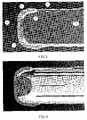
- FIG. 3is a longitudinal cross section of the cover with an inserted device
- FIG. 4is a longitudinal cross section of the cover without device
- FIG. 5is a perspective view of the rear of the cover
- FIG. 6is a transverse cross section of the cover with an inserted portable device
- FIG. 7is a transverse cross section of the cover without device
- FIG. 8is a longitudinal section of the cover without device
- FIG. 9is a perspective view of the cover looking into an opening
- FIG. 10is a perspective view of the cover with an inserted device
- FIG. 11is a perspective view of the cover without the device.
- FIG. 12is an enlarged cross sectional view of the opening of the cover with a cap arranged over the opening.
- FIG. 1 and FIG. 2a cover containing a portable device 10 is shown.
- the covercomprises a cap 1 of substantially non-resilient material closed over an opening 3 of the main body 2 of the cover at the left of FIGS. 1 , 3 and 4 .
- the opening 3is preferably arranged at the smallest side so that the sealing length, Ls, is as small as possible.
- the cap 1is substantially smooth on the inside and is of a material that is less resilient than the cover in order to enhance the stability of the cover, e.g. hard plastic, hard rubber or the like.
- a sound hole 4is also visible.
- An air permeable membrane(not shown) may be arranged at the sound hole in order to keep the cover waterproof.
- the so called inner seal 7the white line along the resilient part of the main body, is shown.
- the tapered shape of the resilient partis clearly disclosed and as can be seen the inner seal is formed corresponding to the tapering part of the main body of the cover.
- the tapering part of the main bodyis formed around the bottom of the portable device 10 and one side of the main body is formed in a shape to provide space 9 for keys of the portable device 10 .
- the outer surface of the resilient part 8 around the openingis provided with at least one, preferably two, beads 5 and 6 .
- the outer bead 5provides the main seal, and the somewhat smaller bead, closer to the opening, provides a secondary seal 6 .
- the beadsare the same size.
- the capWhen the cap is attached to the cover, the beads are compressed to form tight seals, shown in the figures as gray areas on the beads.
- the capmay be provided with inner recesses to accommodate the beads 5 and 6 , but such recesses are not necessary.
- the surface of the resilient part 8may instead be arranged with no beads rendering a smooth surface wherein in the cap 1 is press fitted over the resilient part.
- the resilient part 8 of the main bodyforms an upper lip and a lower lip surrounding the opening 3 .
- the interior of the upper and the lower liphas a curved shape.
- the interior as well as the exterior of the lipshave a substantially planar shape, resulting in the use of a cap with corresponding interior.
- a shoulder 11 , 12is arranged on the main body of the cover to form a stop lip for each edge of the cap 1 to press against in order to form tight seals between the main body of the cover 2 and the cap 1 , enhancing the seal between the cap 1 and the main body 2 of the cover.
- the interior of the coveris provided with protruding longitudinal ribs 20 .
- Theses ribsare arranged in order to facilitate the movement of the portable device 10 relative the main body of the cover as well as fixating the portable device in relation to the cover.
- the coveris provided with a number of ribs 201 - 209 projecting on the inside of the cover.
- small gaps or channelsare formed allowing air to flow in and out of the cover as the portable device is pulled out or pushed in, respectively.
- the ribsalso reinforce the cover, even though it is not their primary function.
- the ribsIn order to decrease the friction the ribs must be arranged to let flow of the air pass between the cover and the mobile phone.
- the ribsare extending in a longitudinal direction of the cover, i.e. parallel to the insertion direction of the mobile device. In the illustrated embodiment the ribs extend substantially along the whole cover.
- the ribsare extending in a direction of the cover at an angle to the insertion direction of the mobile device.
- the anglemay e.g. range from 0 degrees (parallel as shown) to approximately 60 degrees, as long as air flow is permitted between the cover and the mobile phone.
- the ribsare replaced by knobs (not shown) or other generally rounded protuberances projecting on the inside of the cover performing the same venting function.
- venting functionmay be performed by a variety of elements.
- each sidethere are two ribs 201 , 202 in the left upper corner as well as the right upper corner 203 , 204 , i.e. towards the side with the keypad, in case of a cover for a mobile telephone, one rib 205 close to the left lower corner, one rib 206 close to the right lower corner and four ribs 209 at the bottom flat side (shown in FIG. 7 and FIG. 9 ).
- the placements of the ribsare made in order to avoid ribs in contact with keys of a mobile phone as well as reinforcing said cover.
- the placements of the ribsare based on the portable device aimed to be using the cover.
- the rib 201is placed in corner forcing the portable device downwards, rendering a small space for the keypad of the portable device.
- a rib 207is shown.
- the rib 207extends partially along the inside of the cover.
- These (a similar one is arranged on the side not shown) ribs 207are arranged on the cover to stabilize the portable device sideways in the cover suitable for an intended model of the portable device.
- the ribs 201 - 206 placed in the cornersare larger, i.e. protruding more from the cover, than the other ribs 207 , 209 extending on a flat surface of the cover.
- the ribsare mainly provided on the resilient parts since the non-resilient parts will not deform and be sucked against the device. It should also be noted that the ribs facilitate the insertion of the portable device in that the air that is compressed by the portable device passes between the cover and the portable device.
- connection part 13is arranged on the cover.
- the connection part 13comprises a protruding section 14 arranged to receive a recess in the cap in order to connect the cap to the cover.
- the connection partmay also comprise a recess 15 that corresponds to a protruding part arranged on the resilient part 8 in order to secure the connection part 13 to the cover 2 .
- the connection partalso provides an extra sealing edge surface between the cap and the cover 2 .
- FIG. 5the cap 1 is shown in a mounted state on the cover, i.e. snapped on the protruding part 14 of the connection part 13 .
- FIG. 5a part 30 containing a sound membrane for letting out sound from the portable device is shown.
- the membraneis an air permeable membrane in order to seal off the portable device from the surrounding dust and the like, and at the same time letting out the sound.
- the cap 1is taken off and the portable device is slid into the cover through the opening 3 . Thereafter, the cap 1 is pressed on the resilient part 8 of the cover providing an inner seal 7 as well as at least one outer seal due to the contact area of the bead.
- FIG. 10a portable device 10 is indicated with an even darker shade as seen through the opening 3 .
- the openingis supposed to be covered by a cap, as shown in FIG. 12 .
- the opening 3has a mouth-like shape with one upper lip 302 and one lower lip 303 extending over the whole width of the cover.
- the openingis provided with a rounded shape 301 extending a distance, D, along the longitudinal direction of the cover. The corners are retracted this distance behind the upper and lower lips.
- Da distance
- the corneris formed as a half circle, but the corner may vary from a small curved shape, i.e. D is relatively short, to a long U-shape, i.e. D is relatively long, just as long as the opening has rounded corners seen from the side of the cover.
- Another aspect of the distance Dis that when the cover is decored from the mould during moulding the permanent deformation of the cover will be as small as possible.
- the shape of the openingresults in that the lips 302 , 303 may be parted to widen the opening without overstraining the material, even at the corners. This means that there is less deformation during decoring of the cover from the mould, resulting in very little permanent deformation, even if the cover is not completely cured during the decoring. Also, it is easy for a user to remove the portable device by parting the lips, or just gripping the phone with a thumb and a finger by the rounded shape 301 of the corners and pulling it outwards, thus slightly parting the upper and lower lips.
- the small stress and deformation of the materialincreases the durability of the cover as well.
- the interior of the upper 302 and lower lip 303has a curved shape.
- the interior as well as the exterior of the lipshave a substantially planar shape.
- a substantially non-resilient protective part 35is disclosed covering the display area of the mobile device in order to stabilize and protect the display of the mobile device.
- plasticsuch as thermoplastic, silicone or the like is pressed or sprayed into the cast forming the cover, i.e. inserted in a heated state in to the mould cast.
- plasticWhen the plastic has cooled down, the part of the cast forming the exterior of the cover is removed revealing the exterior of the cover and the core of the cast, forming the interior of the cover, is removed as well. Due to the shape of the opening 3 the lips are just slightly parted with a minor stress on the rounded corners, resulting in a reduced permanent deformation comparing to a cover without an opening according to the invention.
Landscapes
- Engineering & Computer Science (AREA)
- Signal Processing (AREA)
- Computer Networks & Wireless Communication (AREA)
- Telephone Set Structure (AREA)
- Push-Button Switches (AREA)
- Electrophonic Musical Instruments (AREA)
Abstract
Description
Claims (6)
Priority Applications (8)
| Application Number | Priority Date | Filing Date | Title |
|---|---|---|---|
| US11/617,757US7623898B2 (en) | 2006-06-28 | 2006-12-29 | Cover for portable device |
| JP2009515786AJP4865859B2 (en) | 2006-06-28 | 2007-01-18 | Cover for portable devices |
| AT07726202TATE475258T1 (en) | 2006-06-28 | 2007-01-18 | COVER FOR A PORTABLE DEVICE |
| EP07726202AEP2033418B1 (en) | 2006-06-28 | 2007-01-18 | Cover for portable device |
| PCT/EP2007/050475WO2008000524A1 (en) | 2006-06-28 | 2007-01-18 | Cover for portable device |
| BRPI0712554-2ABRPI0712554A2 (en) | 2006-06-28 | 2007-01-18 | cover to protect a portable device from Water, dust and shock |
| CN2007800210614ACN101461216B (en) | 2006-06-28 | 2007-01-18 | Cover for portable device |
| DE602007007947TDE602007007947D1 (en) | 2006-06-28 | 2007-01-18 | COVER FOR A PORTABLE DEVICE |
Applications Claiming Priority (2)
| Application Number | Priority Date | Filing Date | Title |
|---|---|---|---|
| US80600106P | 2006-06-28 | 2006-06-28 | |
| US11/617,757US7623898B2 (en) | 2006-06-28 | 2006-12-29 | Cover for portable device |
Publications (2)
| Publication Number | Publication Date |
|---|---|
| US20080000937A1 US20080000937A1 (en) | 2008-01-03 |
| US7623898B2true US7623898B2 (en) | 2009-11-24 |
Family
ID=38001787
Family Applications (1)
| Application Number | Title | Priority Date | Filing Date |
|---|---|---|---|
| US11/617,757Active2028-04-01US7623898B2 (en) | 2006-06-28 | 2006-12-29 | Cover for portable device |
Country Status (8)
| Country | Link |
|---|---|
| US (1) | US7623898B2 (en) |
| EP (1) | EP2033418B1 (en) |
| JP (1) | JP4865859B2 (en) |
| CN (1) | CN101461216B (en) |
| AT (1) | ATE475258T1 (en) |
| BR (1) | BRPI0712554A2 (en) |
| DE (1) | DE602007007947D1 (en) |
| WO (1) | WO2008000524A1 (en) |
Cited By (29)
| Publication number | Priority date | Publication date | Assignee | Title |
|---|---|---|---|---|
| US20110157800A1 (en)* | 2007-06-06 | 2011-06-30 | Richardson Curtis R | Protective Enclosure for Electronic Device |
| US8204561B2 (en) | 2009-02-06 | 2012-06-19 | Speculative Product Design, Llc | One piece co-formed exterior hard shell case with an elastomeric liner for mobile electronic devices |
| US8383216B1 (en) | 2011-09-19 | 2013-02-26 | Speculative Product Design, Llc | Case for a portable electronic device with over-molded thermo-formed film |
| US8675359B2 (en)* | 2012-08-01 | 2014-03-18 | Tsan-Nien Chen | Protective cover structure |
| US20140263264A1 (en)* | 2013-03-15 | 2014-09-18 | Robert Bosch Gmbh | Heated Garment and Battery Holster |
| USRE45179E1 (en) | 2005-01-03 | 2014-10-07 | Speculative Product Design, Llc | Portable device case with corner protector |
| US8965458B2 (en) | 2009-08-21 | 2015-02-24 | Otter Products, Llc | Protective cushion cover for an electronic device |
| US9025317B2 (en) | 2010-03-17 | 2015-05-05 | Otter Products, Llc | Multi-material protective case for sliding/articulating/rotating handheld electronic devices |
| US9107299B2 (en) | 2010-10-12 | 2015-08-11 | Treefrog Developments, Inc. | Housing for encasing an electronic device |
| US9114923B2 (en)* | 2001-11-19 | 2015-08-25 | Otter Products, Llc | Protective enclosure for electronic device |
| US9167063B2 (en) | 2009-11-19 | 2015-10-20 | Otter Products, Llc | Acoustic isolation mechanism |
| US9165550B2 (en) | 2009-11-19 | 2015-10-20 | Otter Products, Llc | Acoustic isolation mechanism with membrane |
| US9220328B2 (en) | 2013-05-18 | 2015-12-29 | Otter Products, Llc | Waterproof protective case for an electronic device |
| US9241551B2 (en) | 2012-06-13 | 2016-01-26 | Otter Products, Llc | Protective case with compartment |
| US9300078B2 (en) | 2013-08-23 | 2016-03-29 | Otter Products, Llc | Waterproof housing for mobile electronic device and waterproof adapter for accessory device |
| US9545140B1 (en) | 2015-07-19 | 2017-01-17 | Otter Products, Llc | Protective enclosure for an electronic device |
| US9549598B2 (en) | 2010-10-12 | 2017-01-24 | Treefrog Developments, Inc. | Housing for encasing an electronic device |
| US9577697B2 (en) | 2015-05-27 | 2017-02-21 | Otter Products, Llc | Protective case with stylus access feature |
| US9960521B2 (en) | 2016-02-24 | 2018-05-01 | Otter Products, Llc | Connector for fluidly sealing an aperture of a protective case |
| US9986802B2 (en) | 2008-12-29 | 2018-06-05 | Otter Products, Llc | Protective cushion cover for an electronic device |
| US10005611B2 (en) | 2012-06-01 | 2018-06-26 | Treefrog Developments, Inc. | Protective case for electronic device |
| US10159320B2 (en) | 2016-09-07 | 2018-12-25 | Otter Products, Llc | Protective enclosure for encasing an electronic device |
| US20190029383A1 (en)* | 2017-07-28 | 2019-01-31 | Otter Products, Llc | Protective case with sealed audio port |
| US10396843B2 (en) | 2011-06-13 | 2019-08-27 | Treefrog Developments, Inc. | Protective encasement for a mobile computing device |
| US10420406B2 (en) | 2017-02-16 | 2019-09-24 | Otter Products, Llc | Protective cover for electronic device |
| US10827809B2 (en) | 2018-04-05 | 2020-11-10 | Otter Products, Llc | Protective case for electronic device |
| US11522571B2 (en) | 2019-10-28 | 2022-12-06 | Speculative Product Design, Llc | Mobile device case with bonded soft resin insert and shell |
| US12273138B2 (en) | 2021-10-28 | 2025-04-08 | Otter Products, Llc | Protective enclosure for an electronic device |
| USRE50359E1 (en) | 2009-08-12 | 2025-04-08 | Tech-Sessories, Inc. | One-piece protective case |
Families Citing this family (3)
| Publication number | Priority date | Publication date | Assignee | Title |
|---|---|---|---|---|
| WO2013070599A1 (en)* | 2011-11-09 | 2013-05-16 | Case-Mate, Inc. | Ruggedized case for hand-held electronic device |
| WO2017042970A1 (en)* | 2015-09-11 | 2017-03-16 | 喜久 廣田 | Case for portable terminal |
| TWI789463B (en)* | 2017-11-30 | 2023-01-11 | 美商康寧公司 | Vacuum mold apparatus, systems, and methods for forming curved mirrors |
Citations (15)
| Publication number | Priority date | Publication date | Assignee | Title |
|---|---|---|---|---|
| US5873456A (en)* | 1996-09-23 | 1999-02-23 | Hull; John R. | Remote control device protective pouch |
| WO2000051315A1 (en) | 1999-02-24 | 2000-08-31 | Moduleo Oy | Mobile phone case |
| WO2000062509A1 (en) | 1999-04-13 | 2000-10-19 | Matsushita Electric Industrial Co., Ltd. | Portable phone and method of forming waterproof case of the phone |
| WO2002003828A1 (en) | 2000-07-10 | 2002-01-17 | Moduleo Oy | Casing for a mobile telephone |
| WO2002011161A2 (en) | 2000-07-31 | 2002-02-07 | Johan Kruger | Protective cover |
| US20020136557A1 (en)* | 2001-03-21 | 2002-09-26 | Takashi Shimamura | Waterproof case for portable device |
| WO2002088914A1 (en) | 2001-04-30 | 2002-11-07 | Nokia Corporation | Enclosure for wireless communication device |
| EP1301011A2 (en) | 2001-10-05 | 2003-04-09 | Nokia Corporation | User changeable electronic device/mobile phone covers and method |
| WO2003041288A2 (en) | 2001-11-03 | 2003-05-15 | Jean Goros | Protective sleeve for small electronic devices |
| US20030111366A1 (en) | 2001-12-14 | 2003-06-19 | Enners Ryan S. | Waterproof casing for Hewlettt-Packard Jornada portable personal computer |
| US6731913B2 (en)* | 2002-01-30 | 2004-05-04 | Nokia Corporation | Elastomeric enclosure |
| US20040154941A1 (en)* | 2003-02-06 | 2004-08-12 | Montler Mike F. | Flexible hygienic remote control enclosure |
| US20040203486A1 (en) | 2002-07-31 | 2004-10-14 | Robert Shepherd | Smart pouch cover for mobile device |
| US20050116003A1 (en) | 2003-12-01 | 2005-06-02 | Butler Michael R. | Portable, waterproof case for storing items |
| US7050841B1 (en) | 2004-08-30 | 2006-05-23 | Hideki Francis Onda | Protective enclosure for a hand-held electronic device that both stores and plays digital audio recordings |
Family Cites Families (5)
| Publication number | Priority date | Publication date | Assignee | Title |
|---|---|---|---|---|
| JPS5441721Y2 (en)* | 1973-12-10 | 1979-12-05 | ||
| JP2000151772A (en)* | 1998-11-12 | 2000-05-30 | Matsushita Electric Ind Co Ltd | Mobile terminal device |
| JP4265095B2 (en)* | 2000-09-11 | 2009-05-20 | ソニー株式会社 | Waterproof case for electronic equipment |
| JP2006242996A (en)* | 2005-02-28 | 2006-09-14 | Asahi:Kk | Waterproof case |
| JP2006319433A (en)* | 2005-05-10 | 2006-11-24 | Takaharu Nonoda | Case for mobile goods |
- 2006
- 2006-12-29USUS11/617,757patent/US7623898B2/enactiveActive
- 2007
- 2007-01-18JPJP2009515786Apatent/JP4865859B2/ennot_activeExpired - Fee Related
- 2007-01-18EPEP07726202Apatent/EP2033418B1/ennot_activeNot-in-force
- 2007-01-18CNCN2007800210614Apatent/CN101461216B/ennot_activeExpired - Fee Related
- 2007-01-18DEDE602007007947Tpatent/DE602007007947D1/enactiveActive
- 2007-01-18ATAT07726202Tpatent/ATE475258T1/ennot_activeIP Right Cessation
- 2007-01-18BRBRPI0712554-2Apatent/BRPI0712554A2/ennot_activeIP Right Cessation
- 2007-01-18WOPCT/EP2007/050475patent/WO2008000524A1/enactiveApplication Filing
Patent Citations (16)
| Publication number | Priority date | Publication date | Assignee | Title |
|---|---|---|---|---|
| US5873456A (en)* | 1996-09-23 | 1999-02-23 | Hull; John R. | Remote control device protective pouch |
| WO2000051315A1 (en) | 1999-02-24 | 2000-08-31 | Moduleo Oy | Mobile phone case |
| WO2000062509A1 (en) | 1999-04-13 | 2000-10-19 | Matsushita Electric Industrial Co., Ltd. | Portable phone and method of forming waterproof case of the phone |
| WO2002003828A1 (en) | 2000-07-10 | 2002-01-17 | Moduleo Oy | Casing for a mobile telephone |
| WO2002011161A2 (en) | 2000-07-31 | 2002-02-07 | Johan Kruger | Protective cover |
| US20020136557A1 (en)* | 2001-03-21 | 2002-09-26 | Takashi Shimamura | Waterproof case for portable device |
| WO2002088914A1 (en) | 2001-04-30 | 2002-11-07 | Nokia Corporation | Enclosure for wireless communication device |
| EP1301011A2 (en) | 2001-10-05 | 2003-04-09 | Nokia Corporation | User changeable electronic device/mobile phone covers and method |
| WO2003041288A2 (en) | 2001-11-03 | 2003-05-15 | Jean Goros | Protective sleeve for small electronic devices |
| US20030111366A1 (en) | 2001-12-14 | 2003-06-19 | Enners Ryan S. | Waterproof casing for Hewlettt-Packard Jornada portable personal computer |
| US6731913B2 (en)* | 2002-01-30 | 2004-05-04 | Nokia Corporation | Elastomeric enclosure |
| US20040203486A1 (en) | 2002-07-31 | 2004-10-14 | Robert Shepherd | Smart pouch cover for mobile device |
| US6980777B2 (en) | 2002-07-31 | 2005-12-27 | Nokia Corporation | Smart pouch cover for mobile device |
| US20040154941A1 (en)* | 2003-02-06 | 2004-08-12 | Montler Mike F. | Flexible hygienic remote control enclosure |
| US20050116003A1 (en) | 2003-12-01 | 2005-06-02 | Butler Michael R. | Portable, waterproof case for storing items |
| US7050841B1 (en) | 2004-08-30 | 2006-05-23 | Hideki Francis Onda | Protective enclosure for a hand-held electronic device that both stores and plays digital audio recordings |
Non-Patent Citations (2)
| Title |
|---|
| Office Action mailed Jun. 8, 2009 from related U.S. Appl. No. 11/617,747. |
| Office Action mailed on Jun. 2, 2009 from related U.S. Appl. No. 11/617,746. |
Cited By (58)
| Publication number | Priority date | Publication date | Assignee | Title |
|---|---|---|---|---|
| US9114923B2 (en)* | 2001-11-19 | 2015-08-25 | Otter Products, Llc | Protective enclosure for electronic device |
| USRE45179E1 (en) | 2005-01-03 | 2014-10-07 | Speculative Product Design, Llc | Portable device case with corner protector |
| US9173314B2 (en) | 2007-06-06 | 2015-10-27 | Otter Products, Llc | Protective enclosure for an electronic device |
| US9609930B2 (en) | 2007-06-06 | 2017-04-04 | Otter Products, Llc | Protective enclosure for an electronic device |
| US10165839B2 (en) | 2007-06-06 | 2019-01-01 | Otter Products, Llc | Protective cover for a portable electronic device |
| US9498033B2 (en) | 2007-06-06 | 2016-11-22 | Otter Products, Llc | Protective enclosure for an electronic device |
| US9888753B2 (en) | 2007-06-06 | 2018-02-13 | Otter Products, Llc | Protective enclosure for a portable electronic device |
| US20110157800A1 (en)* | 2007-06-06 | 2011-06-30 | Richardson Curtis R | Protective Enclosure for Electronic Device |
| US8395894B2 (en)* | 2007-06-06 | 2013-03-12 | Otter Products, Llc | Protective enclosure for electronic device |
| US9986802B2 (en) | 2008-12-29 | 2018-06-05 | Otter Products, Llc | Protective cushion cover for an electronic device |
| US8204561B2 (en) | 2009-02-06 | 2012-06-19 | Speculative Product Design, Llc | One piece co-formed exterior hard shell case with an elastomeric liner for mobile electronic devices |
| US9136897B2 (en) | 2009-02-06 | 2015-09-15 | Samsonite IP Holdings S.ár.l. | One piece co-formed exterior hard shell case with an elastomeric liner for mobile electronic devices |
| US8755852B2 (en) | 2009-02-06 | 2014-06-17 | Speculative Product Design, Llc | One piece co-formed exterior hard shell case with an elastomeric liner for mobile electronic devices |
| US9451816B2 (en) | 2009-02-06 | 2016-09-27 | Samsonite Ip Holdings S.Àr.L. | One piece co-formed exterior hard shell case with an elastomeric liner for mobile electronic devices |
| USRE50359E1 (en) | 2009-08-12 | 2025-04-08 | Tech-Sessories, Inc. | One-piece protective case |
| US9580221B2 (en) | 2009-08-21 | 2017-02-28 | Otter Products, Llc | Protective cushion cover for an electronic device |
| US8965458B2 (en) | 2009-08-21 | 2015-02-24 | Otter Products, Llc | Protective cushion cover for an electronic device |
| US10966496B2 (en) | 2009-08-21 | 2021-04-06 | Otter Products, Llc | Protective cushion cover for an electronic device |
| US9167063B2 (en) | 2009-11-19 | 2015-10-20 | Otter Products, Llc | Acoustic isolation mechanism |
| US9165550B2 (en) | 2009-11-19 | 2015-10-20 | Otter Products, Llc | Acoustic isolation mechanism with membrane |
| US9433271B2 (en) | 2009-11-19 | 2016-09-06 | Otter Products, Llc | Protective cover with an acoustic isolation mechanism |
| US9025317B2 (en) | 2010-03-17 | 2015-05-05 | Otter Products, Llc | Multi-material protective case for sliding/articulating/rotating handheld electronic devices |
| US9549598B2 (en) | 2010-10-12 | 2017-01-24 | Treefrog Developments, Inc. | Housing for encasing an electronic device |
| US10299554B2 (en) | 2010-10-12 | 2019-05-28 | Treefrog Developments, Inc. | Housing for encasing an electronic device |
| US9380723B2 (en) | 2010-10-12 | 2016-06-28 | Treefrog Developments, Inc. | Housing for encasing an electronic device |
| US9247661B2 (en) | 2010-10-12 | 2016-01-26 | Treefrog Developments, Inc. | Housing for encasing an electronic device |
| US9439314B2 (en) | 2010-10-12 | 2016-09-06 | Treefog Developments, Inc. | Housing for encasing an electronic device |
| US10716377B2 (en) | 2010-10-12 | 2020-07-21 | Treefrog Developments, Inc. | Housing for encasing an object |
| US9955762B2 (en) | 2010-10-12 | 2018-05-01 | Treefrog Developments, Inc. | Housing for encasing an electronic device |
| US9179562B2 (en) | 2010-10-12 | 2015-11-03 | Treefrog Developments, Inc. | Housing for encasing an object |
| US9107299B2 (en) | 2010-10-12 | 2015-08-11 | Treefrog Developments, Inc. | Housing for encasing an electronic device |
| US10396843B2 (en) | 2011-06-13 | 2019-08-27 | Treefrog Developments, Inc. | Protective encasement for a mobile computing device |
| US8383216B1 (en) | 2011-09-19 | 2013-02-26 | Speculative Product Design, Llc | Case for a portable electronic device with over-molded thermo-formed film |
| US10005611B2 (en) | 2012-06-01 | 2018-06-26 | Treefrog Developments, Inc. | Protective case for electronic device |
| US10294016B2 (en) | 2012-06-01 | 2019-05-21 | Treefrog Developments, Inc. | Protective case for electronic device |
| US9241551B2 (en) | 2012-06-13 | 2016-01-26 | Otter Products, Llc | Protective case with compartment |
| US8675359B2 (en)* | 2012-08-01 | 2014-03-18 | Tsan-Nien Chen | Protective cover structure |
| US20140263264A1 (en)* | 2013-03-15 | 2014-09-18 | Robert Bosch Gmbh | Heated Garment and Battery Holster |
| US10973266B2 (en)* | 2013-03-15 | 2021-04-13 | Robert Bosch Tool Corporation | Heated garment and battery holster |
| US9565910B2 (en) | 2013-05-18 | 2017-02-14 | Otter Products, Llc | Waterproof protective case for an electronic device |
| US9220328B2 (en) | 2013-05-18 | 2015-12-29 | Otter Products, Llc | Waterproof protective case for an electronic device |
| US9300078B2 (en) | 2013-08-23 | 2016-03-29 | Otter Products, Llc | Waterproof housing for mobile electronic device and waterproof adapter for accessory device |
| US9560903B2 (en) | 2013-10-07 | 2017-02-07 | Otter Products, Llc | Protective case with compartment including spring |
| US9756916B2 (en) | 2013-10-07 | 2017-09-12 | Otter Products, Llc | Protective case with card storage |
| US9577697B2 (en) | 2015-05-27 | 2017-02-21 | Otter Products, Llc | Protective case with stylus access feature |
| US9621219B1 (en) | 2015-05-27 | 2017-04-11 | Otter Products, Llc | Protective case with stylus access feature |
| US10448718B2 (en) | 2015-07-19 | 2019-10-22 | Otter Products, Llc | Protective enclosure for an electronic device |
| US9545140B1 (en) | 2015-07-19 | 2017-01-17 | Otter Products, Llc | Protective enclosure for an electronic device |
| US9960521B2 (en) | 2016-02-24 | 2018-05-01 | Otter Products, Llc | Connector for fluidly sealing an aperture of a protective case |
| US10159320B2 (en) | 2016-09-07 | 2018-12-25 | Otter Products, Llc | Protective enclosure for encasing an electronic device |
| US10835006B2 (en) | 2016-09-07 | 2020-11-17 | Otter Products, Llc | Protective enclosure for encasing an electronic device |
| US10178902B2 (en) | 2016-09-07 | 2019-01-15 | Otter Products, Llc | Protective enclosure for encasing an electronic device |
| US10420406B2 (en) | 2017-02-16 | 2019-09-24 | Otter Products, Llc | Protective cover for electronic device |
| US20190029383A1 (en)* | 2017-07-28 | 2019-01-31 | Otter Products, Llc | Protective case with sealed audio port |
| US10827809B2 (en) | 2018-04-05 | 2020-11-10 | Otter Products, Llc | Protective case for electronic device |
| US11522571B2 (en) | 2019-10-28 | 2022-12-06 | Speculative Product Design, Llc | Mobile device case with bonded soft resin insert and shell |
| US12009854B2 (en) | 2019-10-28 | 2024-06-11 | Speculative Product Design, Llc | Mobile device case with bonded soft resin insert and shell |
| US12273138B2 (en) | 2021-10-28 | 2025-04-08 | Otter Products, Llc | Protective enclosure for an electronic device |
Also Published As
| Publication number | Publication date |
|---|---|
| EP2033418A1 (en) | 2009-03-11 |
| WO2008000524A1 (en) | 2008-01-03 |
| DE602007007947D1 (en) | 2010-09-02 |
| JP4865859B2 (en) | 2012-02-01 |
| CN101461216B (en) | 2012-05-23 |
| CN101461216A (en) | 2009-06-17 |
| JP2009542062A (en) | 2009-11-26 |
| BRPI0712554A2 (en) | 2012-11-20 |
| EP2033418B1 (en) | 2010-07-21 |
| US20080000937A1 (en) | 2008-01-03 |
| ATE475258T1 (en) | 2010-08-15 |
Similar Documents
| Publication | Publication Date | Title |
|---|---|---|
| US7623898B2 (en) | Cover for portable device | |
| US7647082B2 (en) | Cover for portable device | |
| US7630746B2 (en) | Cover for portable device | |
| US8695798B2 (en) | Case for electronic devices | |
| US9756914B2 (en) | Case for a portable electronic device | |
| US9565910B2 (en) | Waterproof protective case for an electronic device | |
| US7236588B2 (en) | Interlocking cover for mobile terminals | |
| CN102378585B (en) | Electronic device cover and method of making same | |
| US9010537B2 (en) | Protective enclosure for touch screen device | |
| US20040014506A1 (en) | Casing for a mobile telephone | |
| US20130334071A1 (en) | Protective enclosure for touch screen device | |
| EP1321802A3 (en) | Camera and underwater housing having a two-shot moulded knob seat | |
| US10542802B1 (en) | Case for portable electronic device | |
| KR101197173B1 (en) | Protecting case for Bar-type handheld | |
| JP2010087639A (en) | Absorption-side cap and electronic apparatus equipped with the same | |
| KR102073774B1 (en) | Cover member for front and rear cameras of cellular phone and case therefor including the same | |
| WO2016036407A1 (en) | Case for a portable electronic device | |
| KR200476086Y1 (en) | Removable Flip Type Case for Portable Electronic Device | |
| CN109845235A (en) | Shell with internal figure | |
| JP2012186052A (en) | Battery cover for electronic apparatus | |
| KR200387247Y1 (en) | Skin for Digital Camera | |
| KR20140005553A (en) | Mobilephone protective case | |
| JP2010004391A (en) | Casing and mobile terminal |
Legal Events
| Date | Code | Title | Description |
|---|---|---|---|
| AS | Assignment | Owner name:SONY ERICSSON MOBILE COMMUNICATIONS AB, SWEDEN Free format text:ASSIGNMENT OF ASSIGNORS INTEREST;ASSIGNOR:HOLMBERG, PER;REEL/FRAME:018880/0638 Effective date:20060807 | |
| AS | Assignment | Owner name:SONY ERICSSON MOBILE COMMUNICATIONS AB, SWEDEN Free format text:ASSIGNMENT OF ASSIGNORS INTEREST;ASSIGNOR:HOLMBERG, PER;REEL/FRAME:020138/0925 Effective date:20070928 | |
| FEPP | Fee payment procedure | Free format text:PAYOR NUMBER ASSIGNED (ORIGINAL EVENT CODE: ASPN); ENTITY STATUS OF PATENT OWNER: LARGE ENTITY | |
| STCF | Information on status: patent grant | Free format text:PATENTED CASE | |
| FPAY | Fee payment | Year of fee payment:4 | |
| FPAY | Fee payment | Year of fee payment:8 | |
| AS | Assignment | Owner name:SONY MOBILE COMMUNICATIONS AB, SWEDEN Free format text:CHANGE OF NAME;ASSIGNOR:SONY ERICSSON MOBILE COMMUNICATIONS AB;REEL/FRAME:048690/0974 Effective date:20120221 | |
| AS | Assignment | Owner name:SONY CORPORATION, JAPAN Free format text:ASSIGNMENT OF ASSIGNORS INTEREST;ASSIGNOR:SONY MOBILE COMMUNICATIONS AB;REEL/FRAME:048825/0737 Effective date:20190405 | |
| MAFP | Maintenance fee payment | Free format text:PAYMENT OF MAINTENANCE FEE, 12TH YEAR, LARGE ENTITY (ORIGINAL EVENT CODE: M1553); ENTITY STATUS OF PATENT OWNER: LARGE ENTITY Year of fee payment:12 |