US7623602B2 - Iterative interference canceller for wireless multiple-access systems employing closed loop transmit diversity - Google Patents
Iterative interference canceller for wireless multiple-access systems employing closed loop transmit diversityDownload PDFInfo
- Publication number
- US7623602B2 US7623602B2US11/509,920US50992006AUS7623602B2US 7623602 B2US7623602 B2US 7623602B2US 50992006 AUS50992006 AUS 50992006AUS 7623602 B2US7623602 B2US 7623602B2
- Authority
- US
- United States
- Prior art keywords
- signals
- signal
- receive antennas
- providing
- interference
- Prior art date
- Legal status (The legal status is an assumption and is not a legal conclusion. Google has not performed a legal analysis and makes no representation as to the accuracy of the status listed.)
- Active, expires
Links
- 230000000087stabilizing effectEffects0.000claimsabstractdescription77
- 238000000034methodMethods0.000claimsabstractdescription71
- 230000005540biological transmissionEffects0.000claimsabstractdescription7
- 239000011159matrix materialSubstances0.000claimsdescription99
- 239000013598vectorSubstances0.000claimsdescription86
- 239000000470constituentSubstances0.000claimsdescription70
- 238000012545processingMethods0.000claimsdescription49
- 230000004044responseEffects0.000claimsdescription14
- 238000007493shaping processMethods0.000claimsdescription11
- 238000003786synthesis reactionMethods0.000claimsdescription8
- 230000015572biosynthetic processEffects0.000claimsdescription6
- 238000004590computer programMethods0.000claimsdescription5
- 238000004364calculation methodMethods0.000claimsdescription4
- 230000017105transpositionEffects0.000claims6
- 230000002194synthesizing effectEffects0.000claims4
- 230000008569processEffects0.000abstractdescription12
- 238000004891communicationMethods0.000abstractdescription9
- 238000001228spectrumMethods0.000abstractdescription4
- 238000003892spreadingMethods0.000description10
- 238000010586diagramMethods0.000description8
- 230000006870functionEffects0.000description6
- 230000001413cellular effectEffects0.000description2
- 230000001934delayEffects0.000description2
- 238000009826distributionMethods0.000description2
- 238000012432intermediate storageMethods0.000description2
- 102100034665Clathrin heavy chain 2Human genes0.000description1
- 101000946482Homo sapiens Clathrin heavy chain 2Proteins0.000description1
- 239000000654additiveSubstances0.000description1
- 230000000996additive effectEffects0.000description1
- 238000004458analytical methodMethods0.000description1
- 238000013459approachMethods0.000description1
- 238000003491arrayMethods0.000description1
- 230000008901benefitEffects0.000description1
- 238000011156evaluationMethods0.000description1
- 238000009472formulationMethods0.000description1
- 230000006872improvementEffects0.000description1
- 230000010354integrationEffects0.000description1
- 230000003993interactionEffects0.000description1
- 239000000203mixtureSubstances0.000description1
- 238000012986modificationMethods0.000description1
- 230000004048modificationEffects0.000description1
- 238000005457optimizationMethods0.000description1
- 230000010363phase shiftEffects0.000description1
- 230000009467reductionEffects0.000description1
- 238000005070samplingMethods0.000description1
- 230000011664signalingEffects0.000description1
- 230000007480spreadingEffects0.000description1
- 238000010561standard procedureMethods0.000description1
- 238000003860storageMethods0.000description1
Images


Classifications
- H—ELECTRICITY
- H04—ELECTRIC COMMUNICATION TECHNIQUE
- H04B—TRANSMISSION
- H04B1/00—Details of transmission systems, not covered by a single one of groups H04B3/00 - H04B13/00; Details of transmission systems not characterised by the medium used for transmission
- H04B1/69—Spread spectrum techniques
- H04B1/707—Spread spectrum techniques using direct sequence modulation
- H04B1/7097—Interference-related aspects
- H04B1/7103—Interference-related aspects the interference being multiple access interference
- H04B1/7107—Subtractive interference cancellation
- H—ELECTRICITY
- H04—ELECTRIC COMMUNICATION TECHNIQUE
- H04B—TRANSMISSION
- H04B1/00—Details of transmission systems, not covered by a single one of groups H04B3/00 - H04B13/00; Details of transmission systems not characterised by the medium used for transmission
- H—ELECTRICITY
- H04—ELECTRIC COMMUNICATION TECHNIQUE
- H04B—TRANSMISSION
- H04B1/00—Details of transmission systems, not covered by a single one of groups H04B3/00 - H04B13/00; Details of transmission systems not characterised by the medium used for transmission
- H04B1/69—Spread spectrum techniques
- H04B1/707—Spread spectrum techniques using direct sequence modulation
- H04B1/7097—Interference-related aspects
- H04B1/7103—Interference-related aspects the interference being multiple access interference
- H04B1/7107—Subtractive interference cancellation
- H04B1/71072—Successive interference cancellation
- H—ELECTRICITY
- H04—ELECTRIC COMMUNICATION TECHNIQUE
- H04L—TRANSMISSION OF DIGITAL INFORMATION, e.g. TELEGRAPHIC COMMUNICATION
- H04L25/00—Baseband systems
- H04L25/02—Details ; arrangements for supplying electrical power along data transmission lines
- H04L25/03—Shaping networks in transmitter or receiver, e.g. adaptive shaping networks
- H04L25/03006—Arrangements for removing intersymbol interference
- H—ELECTRICITY
- H04—ELECTRIC COMMUNICATION TECHNIQUE
- H04B—TRANSMISSION
- H04B1/00—Details of transmission systems, not covered by a single one of groups H04B3/00 - H04B13/00; Details of transmission systems not characterised by the medium used for transmission
- H04B1/69—Spread spectrum techniques
- H04B1/707—Spread spectrum techniques using direct sequence modulation
- H04B1/7097—Interference-related aspects
- H04B1/7103—Interference-related aspects the interference being multiple access interference
- H04B1/7107—Subtractive interference cancellation
- H04B1/71075—Parallel interference cancellation
- H—ELECTRICITY
- H04—ELECTRIC COMMUNICATION TECHNIQUE
- H04B—TRANSMISSION
- H04B1/00—Details of transmission systems, not covered by a single one of groups H04B3/00 - H04B13/00; Details of transmission systems not characterised by the medium used for transmission
- H04B1/69—Spread spectrum techniques
- H04B1/707—Spread spectrum techniques using direct sequence modulation
- H04B1/7097—Interference-related aspects
- H04B1/711—Interference-related aspects the interference being multi-path interference
- H04B1/7115—Constructive combining of multi-path signals, i.e. RAKE receivers
- H—ELECTRICITY
- H04—ELECTRIC COMMUNICATION TECHNIQUE
- H04B—TRANSMISSION
- H04B7/00—Radio transmission systems, i.e. using radiation field
- H04B7/02—Diversity systems; Multi-antenna system, i.e. transmission or reception using multiple antennas
- H04B7/04—Diversity systems; Multi-antenna system, i.e. transmission or reception using multiple antennas using two or more spaced independent antennas
- H04B7/06—Diversity systems; Multi-antenna system, i.e. transmission or reception using multiple antennas using two or more spaced independent antennas at the transmitting station
- H04B7/0613—Diversity systems; Multi-antenna system, i.e. transmission or reception using multiple antennas using two or more spaced independent antennas at the transmitting station using simultaneous transmission
- H04B7/0615—Diversity systems; Multi-antenna system, i.e. transmission or reception using multiple antennas using two or more spaced independent antennas at the transmitting station using simultaneous transmission of weighted versions of same signal
- H04B7/0619—Diversity systems; Multi-antenna system, i.e. transmission or reception using multiple antennas using two or more spaced independent antennas at the transmitting station using simultaneous transmission of weighted versions of same signal using feedback from receiving side
- H04B7/0621—Feedback content
- H04B7/0634—Antenna weights or vector/matrix coefficients
- H—ELECTRICITY
- H04—ELECTRIC COMMUNICATION TECHNIQUE
- H04L—TRANSMISSION OF DIGITAL INFORMATION, e.g. TELEGRAPHIC COMMUNICATION
- H04L25/00—Baseband systems
- H04L25/02—Details ; arrangements for supplying electrical power along data transmission lines
- H04L25/03—Shaping networks in transmitter or receiver, e.g. adaptive shaping networks
- H04L25/03006—Arrangements for removing intersymbol interference
- H04L2025/0335—Arrangements for removing intersymbol interference characterised by the type of transmission
- H04L2025/03375—Passband transmission
Definitions
- the present inventionrelates generally to cancellation of intra-channel and inter-channel interference in coded spread spectrum wireless communications systems having multiple transmit antennas and employing closed loop channel information fed back from a receiver to a transmitter. More specifically, the invention exploits spatial diversity afforded by multiple transmit and receive antennas, in combination with an interference-cancellation unit that performs symbol-estimate weighting, subtractive cancellation with a stabilizing step-size, and mixed-decision symbol estimation.
- a communication resourceis divided into code-space subchannels allocated to different users.
- a plurality of subchannel signals received by a wireless terminalmay correspond to different users and/or different subchannels allocated to a particular user.
- a single transmitterbroadcasts different messages to different receivers, such as a base station in a wireless communication system serving a plurality of mobile terminals
- the channel resourceis subdivided in order to distinguish between messages intended for each mobile.
- each mobile terminalby knowing its allocated subchannel(s), may decode messages intended for it from the superposition of received signals.
- a base stationtypically separates signals it receives into subchannels in order to differentiate between users.
- received signalsare superpositions of time-delayed and complex-scaled versions of the transmitted signals.
- Multipathcan cause several types of interference. Intra-channel interference occurs when the multipath time-spreading causes subchannels to leak into other subchannels. For example, forward-link subchannels that are orthogonal at the transmitter may not be orthogonal at the receiver.
- inter-channel interferencemay result from unwanted signals received from other base stations.
- These types of interferencecan degrade communications by causing a receiver to incorrectly decode received transmissions, thus increasing a receiver's error floor. Interference may degrade communications in other ways. For example, interference may diminish the capacity of a communication system, decrease the region of coverage, and/or decrease maximum data rates. For these reasons, a reduction in interference can improve reception of selected signals while addressing the aforementioned limitations due to interference.
- the use of multiple transmit antennasprovides flexibility for shaping transmissions and, if intelligently used, allows for interference cancellation to improve receiver performance over what can be accomplished with a single transmit antenna.
- Multiple transmit antennasmay be employed in a wireless system with the aim of increasing the signal quality at the receiver. This improvement may be obtained by beamforming, in which case the channel linking each transmit and receive antenna pair is measured at the receiver and fed back through a dedicated channel to the transmitter.
- the transmittermay determine a set of complex weighting coefficients (each corresponding to one antenna) that adapt the phase and/or amplitude of a common information signal transmitted to the receiver across each antenna.
- the weightsmay be chosen to maximize power at the receiver, subject to a constraint on the total transmit power.
- the receivermay calculate the weights, which may be fed back across the dedicated back channel. In this manner, an additional diversity advantage may be gained over the wireless medium and the (average) inter-channel interference may be reduced, as the base stations do not transmit power isotropically to all users in their respective cells.
- embodiments of the present inventionmay provide a generalized interference-canceling receiver for canceling intra-channel and/or inter-channel interference in multiple-access, coded-waveform transmissions that are formed by modulating the same information across a plurality of transmit antennas.
- Each associated transmit-antenna chainintroduces a unique user-specific amplitude weight and phase shift to a user-specific waveform, with the purpose of maximizing the signal-to-noise ratio (or the total power) at each user-specific receiver.
- the transmitted signalspropagate through a frequency-selective communication channel and are received by one or more receive antennas.
- Receiver embodimentsmay be designed, adapted, and implemented explicitly in software or programmed hardware, or implicitly in standard Rake-based hardware. Embodiments may be employed in user equipment on the downlink or in a base station on the uplink.
- a systemis configured for canceling interference from signals in a plurality of receive antennas received from a plurality of transmit antennas wherein closed loop transmit waveform shaping is employed.
- a calculation meanscomprising a combining means, a despreading means, and a mixed-decision means is configured for determining a set of dominant beamforming weights for transmit antennas of each of a plurality of transmit sources.
- the combining meansis configured for combining signals from the plurality of receive antennas for each of the plurality of transmit sources for producing a plurality of combined signals.
- the combining meansmay include, by way of example, but without limitation, an adder or combiner configured to sum a plurality of input signals.
- the despreading meansis configured for employing the set of dominant beamforming weights to resolve the plurality of combined signals onto a signal basis for the plurality of transmit sources to produce soft symbol estimates.
- the despreading meansmay include, by way of example, but without limitation, a channel estimator, a PN decoder, and a Walsh decoder.
- the mixed-decision meansis configured for performing a mixed decision on each of the soft symbol estimates to produce initial symbol decisions.
- the mixed-decision meansmay include, by way of example, but without limitation, a combination of hardware and software configured to produce soft and/or hard symbol estimates.
- the mixed-decision meansmay comprise a de-biasing means configured for scaling the input symbol estimates with a scale factor to remove bias computed on the input symbol estimates.
- Each de-biased input symbol estimatemay be processed irrespective of other symbol estimates to produce a hard decision that quantizes the de-biased input symbol estimate onto a nearby constellation point, or a soft decision that scales the de-biased input symbol estimate.
- the systemmay further comprise a sequential interference cancellation means configured for producing interference-cancelled versions of the initial symbol decisions.
- the sequential interference cancellation meanscomprises a summing means for summing constituent signals for each of the plurality of receive antennas to a corresponding scaled error signal to produce a combined signal, and a resolving means configured for resolving the combined signals across antennas onto the signal basis for the plurality of transmit sources, whereby the resolving is performed with respect to multipath structure determined from the set of dominant beamforming weights.
- the sequential interference cancellation meanscomprises a Rake-synthesis means configured for producing synthesized Rake finger signals for each of the plurality of receive antennas, the synthesized Rake finger signals emulating signals that would be received in response to weighted symbol decisions being employed by at least one of the plurality of transmit sources, and a subtraction means configured for performing per-antenna subtraction of a sum of the synthesized Rake finger signals from a corresponding received signal to produce an error signal.
- the sequential interference cancellation meanscomprises a resolving means configured for resolving a residual signal from each of the plurality of antennas onto the signal basis for the plurality of transmit sources for producing a plurality of per-antenna resolved signals, a combining means configured for combining the per-antenna resolved signals for producing a combined signal, a stabilizing step size means configured for scaling the combined signals with a stabilizing step size for producing a scaled signal, and a summing means configured for summing weighted input symbol decisions with the scaled signal for generating a set of interference-cancelled constituents.
- the sequential interference cancellation meanscomprises a weighting module configured for applying soft weights to a plurality of input symbol decisions, a mixed decision module configured for performing mixed decisions on soft symbol estimates, and a step-size module configured to scale a residual signal with a stabilizing step size.
- Embodiments of the inventionmay be employed in any receiver configured to support the standard offered by the 3 rd -Generation Partnership Project 2 (3GPP2) consortium and embodied in a set of documents, including “TR-45.5 Physical Layer Standard for cdma2000 Spread Spectrum Systems,” “C.S0005-A Upper Layer (Layer 3) Signaling Standard for cdma2000 Spread Spectrum Systems,” and “C.S0024 CDMA2000 High Rate Packet Data Air Interface Specification” (i.e., the CDMA2000 standard).
- 3GPP23 rd -Generation Partnership Project 2
- Receivers and cancellation systems described hereinmay be employed in subscriber-side devices (e.g., cellular handsets, wireless modems, and consumer premises equipment) and/or server-side devices (e.g., cellular base stations, wireless access points, wireless routers, wireless relays, and repeaters). Chipsets for subscriber-side and/or server-side devices may be configured to perform at least some of the receiver and/or cancellation functionality of the embodiments described herein.
- subscriber-side devicese.g., cellular handsets, wireless modems, and consumer premises equipment
- server-side devicese.g., cellular base stations, wireless access points, wireless routers, wireless relays, and repeaters.
- Chipsets for subscriber-side and/or server-side devicesmay be configured to perform at least some of the receiver and/or cancellation functionality of the embodiments described herein.
- FIG. 1Various functional elements, separately or in combination, depicted in the figures may take the form of a microprocessor, digital signal processor, application specific integrated circuit, field programmable gate array, or other logic circuitry programmed or otherwise configured to operate as described herein. Accordingly, embodiments may take the form of programmable features executed by a common processor or a discrete hardware unit.
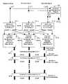
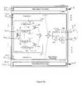
- FIG. 1is a general schematic illustrating an iterative interference canceller in accordance with one embodiment of the invention.
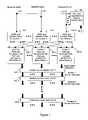
- FIG. 2is a block diagram of a per-antenna front-end Rake and combiner employing dominant beamforming reception.
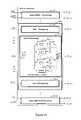
- FIG. 3is a block diagram of module 102 .
- sshown in FIG. 1 , configured for performing per base-station, front-end combining across antennas, de-spreading, and calculating initial symbol estimates.
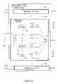
- FIG. 4is a general schematic of an interference cancellation unit configured to process signals from multiple receive antennas.
- FIG. 5 aillustrates an apparatus configured for generating multipath finger constituent signals.
- FIG. 5 billustrates an apparatus configured for generating user constituent signals
- FIG. 6 ais a block diagram of an ICU configured to process user constituent signals.
- FIG. 6 bis a block diagram of an ICU configured to process finger constituent signals.
- FIG. 7 ashows an apparatus configured for performing Rake processing and combining (such as described with respect to steps 405 . 1 - 405 .A shown in FIG. 4 ) on interference-cancelled finger constituent signals for each antenna.
- FIG. 7 bshows an apparatus configured for performing Rake processing and combining (such as described with respect to steps 405 . 1 - 405 .A shown in FIG. 4 ) on interference-cancelled user constituent signals for each antenna.
- FIG. 8shows an apparatus configured to produce the updated symbol estimates described with respect to step 406 . 1 - 406 .B in FIG. 4 .
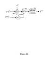
- FIG. 9 ais a block diagram illustrating an embodiment of an interference cancellation unit wherein subtractive cancellation takes place after signal de-spreading.
- FIG. 9 billustrates the final step performed by an interference cancellation unit.
- FIG. 10illustrates an explicit implementation of an interference cancellation unit.
- FIG. 11 aillustrates a method for calculating the stabilizing step size when multiple receive antennas are employed.
- FIG. 11 bshows an equivalent method for calculating the difference signal described with respect to FIG. 11 a.
- FIG. 11 cillustrates a method for implicitly calculating a stabilizing step size.
- FIG. 1Various functional elements or steps, separately or in combination, depicted in the figures may take the form of a microprocessor, digital signal processor, application specific integrated circuit, field programmable gate array, or other logic circuitry programmed or otherwise configured to operate as described herein. Accordingly, embodiments may take the form of programmable features executed by a common processor or discrete hardware unit.
- the following formularepresents an analog baseband signal received by antenna a from multiple base stations employing CLTD when a single symbol is transmitted by each user on each symbol period (corresponding to vector-valued beam forming):
- each useremploys a distinct Rake filter matched to the effective multiple-input multiple-output channel that maps the transmitter to the receiver.
- each usermay employ a distinct analysis module matched to its channel to generate interference signals for use in cancellation.
- FIG. 1illustrates components of a receiver in accordance with one embodiment of the invention.
- a beam-forming weight determination module 100determines the vector-valued dominant beam pattern weights ⁇ ⁇ s ⁇ from each transmitter (e.g., base station) s to the receiver, generally with the aid of pilot symbols.
- the weight vector ⁇ ⁇ s ⁇will be different for each user served by basestation s.
- the vector ⁇ sis the transmit weighting vector that would be requested by mobile number 1 from base station s.
- the mobilemay not actually receive data from this particular base station.
- the impulse response of the (discrete) channel linking the n th transmit antenna of base station s and receive antenna a after sampling the received datamay be denoted by h a,s,n .
- the set of transmit weights that maximize the received power at the mobile from this base stationare given by the solution to the following quadratic optimization problem
- the received signals on each antennaare processed by a corresponding primary front-end processor 101 . 1 - 101 .A comprising a Rake matched to the dominant transmit beam pattern and a maximal ratio combiner.
- the outputs of the primary front-end processors 101 . 1 - 101 .Aare organized by base station and processed by secondary front-end processors 102 . 1 - 102 .B in which the outputs are combined across receive antennas and then resolved onto the users' code waveforms via de-spreading so that initial symbol estimates can be determined.
- the symbol estimatesform the inputs into the first of a sequence of interference cancellation units (ICUs) 104 . 1 - 104 .M.
- Each ICU 104 . 1 - 104 .Mmitigates intra-channel and inter-channel interference in the estimates in order to produce improved symbol estimates.
- FIG. 2is a block diagram of a per-antenna front-end Rake and combiner, such as the Rake/Combiner 101 . a shown in FIG. 1 , employing dominant beamforming reception.
- a plurality of processing elements 201 . 1 - 201 .B, each associated with one of a plurality B of base stationsare configured to process the received signals.
- Processing element 201 . s associated with an s th base stationillustrates details that are common to all of the processing elements 201 . 1 - 201 .B.
- a plurality of time-advance blocks 202 . 1 - 202 .Ladvances the signal received by antenna a in accordance with multipath time offsets for the first of a plurality of transmit antennas.
- Weighting modules 202 . 1 - 202 .Lapply channel weights to the time-advanced signals to produce weighted signals corresponding to the first of the plurality of transmit antennas.
- a combiner 203combines the weighted signals to produce a combined signal corresponding to the first of the plurality of transmit antennas. Combined signals corresponding to each of the plurality of transmit antennas are combined 204 to yield a combined output for the a th antenna
- FIG. 3illustrates details of module 102 . s (shown in FIG. 1 ), which is configured for implementing combining across paths, de-spreading, and symbol estimation.
- a combiner 301sums the signals over all of the receive antennas to produce the combined signal for base station s over all paths and all antennas,
- This combined signalis resolved onto user code waveforms by a despreader comprising code multipliers 302 . 1 - 302 .K and integrators 303 . 1 - 303 .K to produce a Rake/Combine/De-Spread output for the k th user of base station s
- each q s,kis processed by a symbol estimator 304 . 1 - 304 .K to produce
- a vector of symbol estimates for base station smay be generated as
- b ⁇ _ s [ 0 ][ b ⁇ s , 1 [ 0 ] ⁇ ⁇ b ⁇ s , 2 [ 0 ] ⁇ ⁇ ... ⁇ ⁇ b ⁇ s , K s [ 0 ] ] T .
- each of the functions described with respect to FIG. 3may be implemented on discrete-time sequences derived from continuous waveforms. More specifically, time advances (or delays) of waveforms becomes shifts by an integer number of samples in discrete-time sequences, and integration becomes summation. This point holds for all such functions described herein.
- FIG. 4illustrates an interference-cancellation method that may be performed by an ICU, such as ICU 104 . 1 .
- ICUs described in U.S. patent application Ser. No. 11/451,688consider a system having a single receive antenna, the method illustrated in FIG. 4 shows how to condition the plurality of received antenna signals for a parallel bank of ICUs, and how to condition their outputs prior to making symbol estimates.
- the inputs into the ICUare symbol estimates for all of the base stations, which are weighted 401 . 1 - 401 .B according to the perceived quality of the estimates using any of the soft-weighting methods described in U.S. patent application Ser. No. 11/451,688.
- the weighting of the k th user of base station sis expressed by
- Equation ⁇ ⁇ 7where ⁇ circumflex over (b) ⁇ s,k [i] is the input symbol estimate and ⁇ s,k [i] is its weighting factor.
- the symbol estimatesmay be concatenated 402 into a single column vector
- b ⁇ _ [ i ][ ( b ⁇ _ 1 [ i ] ) T ⁇ ⁇ ( b ⁇ _ 2 [ i ] ) T ⁇ ... ⁇ ⁇ ( b ⁇ _ B [ i ] ) T ] T so that the weighted symbol estimates are given by ⁇ [i] ⁇ circumflex over (b) ⁇ [i] , where ⁇ [i] is a diagonal matrix containing the weighting factors along its main diagonal.
- the weighted symbol estimates ⁇ [i] ⁇ circumflex over (b) ⁇ [i]are used to synthesize 403 . 1 - 403 .A a set of constituent signals for each antenna If the constituent signals for a given antenna were summed, the result would be an estimate of a signal received by antenna a (without noise) if the elements of ⁇ [i] ⁇ circumflex over (b) ⁇ [i] were transmitted by the plurality of transmit antennas.
- interference cancellation 404 . 1 - 404 .Ais performed on the constituent signals to reduce intra-channel and inter-channel interference.
- Per-antenna Rake processing and combining 405 . 1 - 405 .Aare performed on the resulting interference-cancelled constituents.
- Outputs from Rake processing and combining 405 . 1 - 405 .Aare organized by base station, combined across antennas, resolved onto the users' code waveforms, and processed by symbol estimators 406 . 1 - 406 .B to produce estimated symbols ⁇ circumflex over (b) ⁇ s,k [i+1] for the k th user of base station s after processing by the (i+1) th ICU.
- FIG. 5 aillustrates an apparatus configured for generating multipath finger constituent signals 403 .
- a .A plurality of base-station processing modules 501 . 1 - 501 .Bare configured for processing the weighted symbol estimates ⁇ [i] ⁇ circumflex over (b) ⁇ [i] .
- Processing module 501 . sshows details that are common to the other processing modules 501 . 1 - 501 .B.
- Code multipliers 502 . 1 - 502 .Kproduce estimated transmit signals by scaling each of a plurality of code waveforms with a corresponding weighted symbol estimate.
- a combiner 503combines the estimated transmit signals to produce a superposition signal
- a multipath channel emulatoris configured to process the superposition signal for the channel between the n th transmit antenna of base station s and the a th antenna of the receiver.
- the multipath channel emulatorcomprises a plurality of time-advance modules 504 . 1 . 1 - 504 .N.L and weighting modules 505 . 1 . 1 - 505 .N.L, which produce multipath finger constituent signals
- FIG. 5 billustrates an apparatus configured for generating user constituent signals 403 . a for antenna a.
- a plurality of processors 510 . 1 - 510 .Bare provided for processing signals for each base station.
- Each base station processor 510 . 1 - 510 .Bcomprises a plurality K s of user-signal processors 511 . 1 - 511 .K for each user, such as shown in detail with respect to processor 510 . s.
- User processor 511 . kshows details that are common to each of the K user processors 511 . 1 - 511 .K.
- a code multiplier 512modulates the weighted symbol onto user k's code waveform.
- the modulated waveformis processed by a multipath channel emulator comprising time-advance modules 513 . 1 . 1 - 513 .N.L and complex channel gain modules 514 . 1 . 1 - 514 .N.L.
- a combiner 515sums the emulated multipath signals to produce
- Equation ⁇ ⁇ 10which is the synthesized constituent signal for the k th user of base station s at the a th receive antenna.
- Equation 9employs a four-parameter subscript with n and l denoting transmit antenna number and multipath within the channel defined by the transmit-receive antenna pair, respectively, whereas Equation 10 uses a three-parameter subscript with the subscript k denoting a user constituent.
- the constituent signals for each antennaare processed via interference cancellation 404 . 1 - 404 .A.
- Interference cancellation described in U.S. patent application Ser. No. 11/451,688 for a single antennamay be adapted for embodiments of the present invention in which a plurality of receive antennas are employed and the number of paths are increased due to transmit diversity.
- FIG. 6 ais a block diagram of an ICU configured to process user constituent signals.
- a plurality B of base station processors 601 . 1 - 601 .Bare configured to process the user constituent signals.
- a combiner 602sums user constituent signals associated with base station s to produce a synthesized received signal
- ⁇ tilde over (y) ⁇ a,s,k [i]is the k th user constituent signal from base station s received on the a th receive antenna of the mobile.
- Synthesized received signals corresponding to other base stationsare coupled into a cancellation block 610 , which comprises a combiner 611 that sums the synthesized received signals to produce a combined synthesized received signal,
- a subtraction module 612calculates a difference between the combined synthesized receive signal and the actual received signal to produce a residual, or error, signal y a (t) ⁇ tilde over (y) ⁇ a [i] (t), which is scaled by a complex stabilizing step size ⁇ [i] in step-size module 613 to give ⁇ [i](y a (t) ⁇ tilde over (y) ⁇ a [i] (t)).
- the scaled signal ⁇ [i] (y a (t) ⁇ tilde over (y) ⁇ a [i] (t))is returned to the synthesis block 600 and added in parallel to every constituent signal, such as indicated by combiners 603 . 1 - 603 .K to produce a set of interference-cancelled constituents, given by
- Equation ⁇ ⁇ 11which is the interference-cancelled k th constituent signal from base station s received on the a th antenna of the mobile.
- FIG. 6 bis a block diagram of an ICU configured to process finger constituent signals.
- a plurality B of base station processors 621 . 1 - 621 .Bare configured to process the user constituent signals.
- a combiner 622sums user constituent signals associated with base station s to produce a synthesized received signal associated with that base station,
- ⁇ tilde over (y) ⁇ a,s,n,l [i]is the finger constituent signal on the a th receive antenna corresponding to the l th path from the n th transmit antenna of base station s.
- Synthesized received signals corresponding to other base stationsare coupled into a cancellation block 630 , which comprises a combiner 631 that sums the synthesized received signals to produce a combined synthesized receive signal
- a subtraction module 632calculates the difference between the combined synthesized receive signal and the actual received signal to produce a residual signal, y a (t) ⁇ tilde over (y) ⁇ a [i] (t).
- a step-size module 633scales the residual signal by a complex stabilizing step size ⁇ [i] to produce a scaled signal ⁇ [i] (y a (t) ⁇ tilde over (y) ⁇ a [i] (t)), which is returned to the synthesis block.
- the scaled signal ⁇ [i] (y a (t) ⁇ tilde over (y) ⁇ a [i] (t))is added in parallel by combiners 623 . 1 - 623 .L to each of the constituent signals to produce a set of interference-cancelled constituents.
- the interference-cancelled constituentsare identified by
- Equation ⁇ ⁇ 12which is the interference-cancelled (n,l) th constituent signal from base station s received on the a th antenna of the mobile.
- FIG. 7 ashows an apparatus configured for performing Rake processing and combining (such as described with respect to steps 405 . 1 - 405 .A shown in FIG. 4 ) on interference-cancelled finger constituent signals for antenna a.
- a plurality B of base station processing modules 701 . 1 - 701 .Bare configured for processing finger constituents corresponding to signals transmitted from individual base stations.
- Time-advance modules 702 . 1 - 702 .Lare configured to advance the finger constituent signals by related multipath time shifts.
- Multipliers 703 . 1 - 703 .Lscale the time-shifted constituent signals by the product of dominant beam weights and complex channel gains relative to each transmit antenna.
- a combiner 704sums the scaled, time-shifted signals to produce a maximal ratio combined (MRC) output
- MRCmaximal ratio combined
- FIG. 7 bshows an apparatus configured for performing Rake processing and combining (such as described with respect to steps 405 . 1 - 405 .A shown in FIG. 4 ) on interference-cancelled user constituent signals for each antenna.
- a combiner 711sums the user constituent signals, and the summed signals are processed by a channel emulator comprising time-advance modules 712 . 1 - 712 .L and weighting modules 713 . 1 - 713 .L.
- the weighting modules 713 . 1 - 713 .Lemploy scale factors comprising products of corresponding multipath channel gains and dominant beam weights.
- a combiner 714sums the resulting scaled and time-shifted signals to form the MRC output
- FIG. 8shows an apparatus configured to produce the updated symbol estimates described with respect to step 406 . 1 - 406 .B in FIG. 4 .
- a plurality B of processors 801 . 1 - 801 .Bare configured to process the MRC signals for all of the receive antennas.
- Processor 801 . sshows details that are common to all of the processors 801 . 1 - 801 .B.
- a combiner 802sums the MRC signals from base station s to produce an overall MRC signal for base station s
- a despreadercomprises code multipliers 803 . 1 - 803 .K and integrators 804 . 1 - 804 .K. Resolved signals from the despreader are processed by a plurality of symbol estimators 805 . 1 - 805 .K.
- symbol estimators 805 . 1 - 805 .KVarious types of symbol estimators may be employed, including the mixed-decision symbol estimators described in U.S. patent application Ser. No. 11/451,688.
- antenna combining and despreadingmay be performed prior to interference cancellation, such as illustrated in FIG. 9 a.
- Each of a plurality B of processing blocks 900 . 1 - 900 .Bis configured for processing constituent signals that are common to a particular base station.
- each processing blocksuch as block 900 . s , is a plurality of processing blocks configured for processing constituent signals for each receive antenna 901 . 1 - 901 .A.
- a subtractive canceller 902subtracts constituent signals for each receive antenna from the received signal y a (t) on receive antenna a.
- the resulting residual signalis processed by a Rake with maximal ratio combining, comprising a plurality of time-advance modules 903 . 1 - 903 .L, weighting modules 904 . 1 - 904 .L, and combiners 914 . 1 - 914 .N and 905 .
- Rake outputs from the antennasare summed 906 , and the resulting combined signal is resolved onto the code waveforms of the users associated with the s th base station.
- a despreader configured to resolve the combined signalmay comprise a plurality of code multipliers 907 . 1 - 907 .K and integrators 908 . 1 - 908 .K.
- the output for the k th user of base station sis q s,k ⁇ tilde over (q) ⁇ s,k [i] , where
- the values q s,k and ⁇ tilde over (q) ⁇ s,k [i]may be stacked into vectors over the user index for each base station/antenna pair to form q s ⁇ ⁇ tilde over (q) ⁇ s [i] , where q s is defined in Equation 5. These likewise may be stacked into a single vector over the base station index to give q ⁇ ⁇ tilde over (q) ⁇ [i] . This quantity may also be determined explicitly through a matrix multiplication.
- FIG. 9 billustrates the final step performed by an ICU.
- the difference signal q ⁇ ⁇ tilde over (q) ⁇ [i]is scaled 921 by the stabilizing step size ⁇ [i] and the result is added 923 to the vector F ⁇ [i] ⁇ circumflex over (b) ⁇ [i] , where the value of the implementation matrix F depends on whether finger or user constituents are used.
- symbol estimatesare computed 924 on each element of the vector.
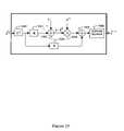
- FIG. 10illustrates an explicit implementation of an ICU.
- Input symbol estimatesare weighted 1000 and multiplied 1001 by a matrix R to produce a vector that is subtracted 1002 from the front-end vector q to produce a difference signal.
- the difference signalis scaled 1003 by the stabilizing step size ⁇ [i] .
- the weighted symbol estimatesare multiplied 1005 by the implementation matrix F, and the resulting weighted vector is added to the scaled difference signal.
- symbol estimatesare computed 1006 from the elements of the resulting vector.
- the matrix Ris the users' correlation matrix at the receiver after combining across antennas. It may be evaluated by
- R a[ R 1 , 1 , a R 1 , 2 , a ... R 1 , B , a R 2 , 1 , a R 2 , 2 , a ... R 2 , B , a ⁇ ⁇ ⁇ R B , 1 , a R B , 2 , a ... R B , B , a ] .
- the (i,j) th element of the cross-correlation matrix R s,s′,ais given by
- the stabilizing step size ⁇ [i]may take any of the forms described in U.S. patent application Ser. No. 11/451,688 that depend on the correlation matrix R, the implementation matrix F, and the weighting matrix ⁇ [i] as defined above. Two of these forms of ⁇ [i] are implicitly calculable, such as described in U.S. patent application Ser. No. 11/451,688 for a single receive antenna.
- FIG. 11 aillustrates a method for calculating the stabilizing step size when multiple receive antennas are employed.
- a plurality A of processors 1101 . 1 - 1101 .Aone for each antenna, provides for performing 1102 Rake processing, combining, and de-spreading on the received signal 1102 and also provides for performing 1103 Rake processing, combining, and de-spreading on the synthesized received signal.
- a difference signalis generated by subtracting 1103 the processed synthesized received signal from the processed received signal.
- the difference signalmay be calculated by first calculating the difference between the received signal and the synthesized received signal prior to Rake processing, combining, and de-spreading, such as shown in FIG. 11 b.
- the resulting difference-signal vector for the a th antennais denoted by ⁇ a [i] , and the sum 1104 of difference-signal vectors over all antennas gives ⁇ [i] .
- a sum of square magnitudes 1105 of the elements of ⁇ [i]i.e., ⁇ ⁇ [i] ⁇ 2
- the elements of ⁇ [i]are used as transmit symbols in a synthesis process 1106 that synthesizes received signals for each antenna.
- the resulting synthesized outputs 1107 . 1 - 1107 .Aare equal to
- the integral of the square magnitude of each of these synthesized signalsis calculated 1108 . 1 - 1108 .A and summed 1109 to provide a denominator of the ratio.
- the ratio of the numerator and the denominatorgives the first version of the step size ⁇ [i] .
- FIG. 11 cAn implicit evaluation of a second version of the step size is illustrated in FIG. 11 c . It too forms a denominator and a numerator in order to calculate the step size.
- the vector ⁇ [i] found in FIG. 11 ais scaled 1150 by the soft weights (as contained in the diagonal matrix ⁇ [i] ).
- the elements of the resulting vectorare used to synthesize 1151 received signals for all of the antennas, such as described with respect to step 1106 in FIG. 11 a .
- Integrals of the square magnitudes of the synthesized signalsare calculated 1152 . 1 - 1152 .A and summed 1153 to produce the denominator.
- the symbol estimates after the i th iterationare scaled 1154 by the square of the soft weights (as contained in the diagonal matrix ( ⁇ [i] ) 2 ) to produce a weighted symbol vector, which is used to synthesize 1156 received signals for all of the antennas, such as described with respect to step 1106 in FIG. 11 a .
- the received signal and the synthesized received signalsare processed 1156 . 1 - 1156 .A relative to each antenna.
- the functionality of the processing 1156 . 1 - 1156 .Ais equivalent to that shown in 1101 . a of FIG. 11 a , which comprises Rake processing, combining, de-spreading, and a difference operation.
- the vector outputs of the antenna processing 1156is equivalent to that shown in 1101 . a of FIG. 11 a , which comprises Rake processing, combining, de-spreading, and a difference operation.
- ⁇ [ i ]( q _ - RF ⁇ ⁇ ⁇ [ i ] ⁇ b _ ⁇ [ i ] ) H ⁇ ( q _ - RF ⁇ ⁇ ⁇ [ i ] ⁇ b ⁇ _ [ i ] ) ( q _ - R ⁇ ⁇ ⁇ [ i ] ⁇ b ⁇ _ [ i ] ) H ⁇ R ⁇ ( q _ - R ⁇ ⁇ ⁇ [ i ] ⁇ b _ ⁇ [ i ] ) Equation ⁇ ⁇ 17 and
- ⁇ [ i ]( q _ - R ⁇ ⁇ ⁇ [ i ] ⁇ F ⁇ ⁇ ⁇ [ i ] ⁇ b _ ⁇ [ i ] ) H ⁇ ⁇ [ i ] ⁇ ( q _ - R ⁇ ⁇ ⁇ [ i ] ⁇ b ⁇ _ [ i ] ) ( q _ - R ⁇ ⁇ ⁇ [ i ] ⁇ b _ ⁇ [ i ] ) H ⁇ ( ⁇ [ i ] ) H ⁇ R ⁇ ⁇ ⁇ [ i ] ⁇ ( q _ - R ⁇ ⁇ ⁇ [ i ] ⁇ b _ ⁇ [ i ] ) , Equation ⁇ ⁇ 18 wherein all quantities are as previously defined.
- step sizein U.S. patent application Ser. No. 11/451,688 depends only on the path gains, and may be generalized to multiple receive antennas according to
- embodiments of the inventionmay be realized in hardware or software and there are several modifications that can be made to the order of operations and structural flow of the processing.
- Those skilled in the artshould recognize that method and apparatus embodiments described herein may be implemented in a variety of ways, including implementations in hardware, software, firmware, or various combinations thereof. Examples of such hardware may include Application Specific Integrated Circuits (ASICs), Field Programmable Gate Arrays (FPGAs), general-purpose processors, Digital Signal Processors (DSPs), and/or other circuitry.
- Software and/or firmware implementations of the inventionmay be implemented via any combination of programming languages, including Java, C, C++, MatlabTM, Verilog, VHDL, and/or processor specific machine and assembly languages.
- Computer programsi.e., software and/or firmware implementing the method of this invention may be distributed to users on a distribution medium such as a SIM card, a USB memory interface, or other computer-readable memory adapted for interfacing with a consumer wireless terminal.
- computer programsmay be distributed to users via wired or wireless network interfaces. From there, they will often be copied to a hard disk or a similar intermediate storage medium.
- the programsWhen the programs are to be run, they may be loaded either from their distribution medium or their intermediate storage medium into the execution memory of a wireless terminal, configuring an onboard digital computer system (e.g. a microprocessor) to act in accordance with the method of this invention. All these operations are well known to those skilled in the art of computer systems.
- modulesmay be provided through the use of dedicated hardware, as well as hardware capable of executing software in association with appropriate software.
- the functionsmay be performed by a single dedicated processor, by a shared processor, or by a plurality of individual processors, some of which may be shared.
- explicit use of the term “processor” or “module”should not be construed to refer exclusively to hardware capable of executing software, and may implicitly include, without limitation, digital signal processor DSP hardware, read-only memory (ROM) for storing software, random access memory (RAM), and non-volatile storage. Other hardware, conventional and/or custom, may also be included.
- the function of any component or device described hereinmay be carried out through the operation of program logic, through dedicated logic, through the interaction of program control and dedicated logic, or even manually, the particular technique being selectable by the implementer as more specifically understood from the context.
Landscapes
- Engineering & Computer Science (AREA)
- Computer Networks & Wireless Communication (AREA)
- Signal Processing (AREA)
- Power Engineering (AREA)
- Mobile Radio Communication Systems (AREA)
- Radio Transmission System (AREA)
Abstract
Description
with the following definitions
- a represents the athantenna of the mobile and ranges from 1 to A;
- (0, T) is the symbol interval;
- B is the number of modeled transmit sources, or base stations, indexed by the subscript s, which ranges from 1 to B, wherein the term “transmit source” or “base station” may include cells or sectors;
- N is the number of transmit antennas employed by each base station;
- La,s,nis the number of resolvable (or modeled) paths from the nthtransmit antenna of base station s to antenna a of the mobile, and is indexed from 1 to La,s,n;
- αa,s,n,land τa,s,n,lare the complex gain and delay, respectively, associated with the lthpath from the nthtransmit antenna of base station s to antenna a of the mobile;
- Ksis the number of active users or code waveform subchannels in base station s sharing the channel via code-division multiplexing, indexed from 1 to Ks;
- us,k(t) is the code waveform (e.g., spreading waveform) of base station s used to carry the kthuser's symbol for that base station on all transmit antennas (e.g., a chip waveform modulated by a user-specific Walsh code and covered with a base-station specific PN cover; the framework, though, is general and is not limited to any particular type of code waveforms);
- ws,n,kis the weighting coefficient applied to the kthuser of base station s prior to transmission from antenna n;
- bs,kis the complex symbol being transmitted for the kthuser of base station s; and
- na(t) is zero-mean complex additive noise on the athantenna that contains both thermal noise and any interference whose structure is not explicitly modeled (e.g., inter-channel interference from unmodeled base stations and intra-channel interference from unmodeled paths).
which may be solved by standard techniques (e.g. Rayleigh quotients). Other formulations of this problem, such as maximizing the received signal-to-noise ratio, may result in different choices for the weights valuesŵs. All users from base station s are processed under the assumption that they employ this common transmit patternŵs. This assumption accurately models the dominant interferers (those that happen to employ this beam pattern). Furthermore, the use of soft weights indicating received quality of each users' symbols will tend to remove those users for which this match is bad.
where
This combined signal is resolved onto user code waveforms by a despreader comprising code multipliers302.1-302.K and integrators303.1-303.K to produce a Rake/Combine/De-Spread output for the kthuser of base station s
The outputs for different users may be stacked to produce a column vector
where the superscript T denotes matrix transpose for base station s. Finally, each qs,kis processed by a symbol estimator304.1-304.K to produce
where the superscript [0] indicates the initial symbol estimate produced by front-end processing. A vector of symbol estimates for base station s may be generated as
where {circumflex over (b)}s,k[i] is the input symbol estimate and γs,k[i] is its weighting factor. The superscript [i] represents the output of the ithICU, with [i=0] representing the front-end processing output prior to the first ICU. The symbol estimates may be concatenated402 into a single column vector
so that the weighted symbol estimates are given by Γ[i]{circumflex over (b)}[i], where Γ[i] is a diagonal matrix containing the weighting factors along its main diagonal.
A multipath channel emulator is configured to process the superposition signal for the channel between the nthtransmit antenna of base station s and the athantenna of the receiver. The multipath channel emulator comprises a plurality of time-advance modules504.1.1-504.N.L and weighting modules505.1.1-505.N.L, which produce multipath finger constituent signals
expressing the lthfinger constituent for the channel between the nthtransmit antenna of base station s and the athreceive antenna of the mobile.
which is the synthesized constituent signal for the kthuser of base station s at the athreceive antenna. Note that
where {tilde over (y)}a,s,k[i] is the kthuser constituent signal from base station s received on the athreceive antenna of the mobile.
on the athreceive antenna. A
which is the interference-cancelled kthconstituent signal from base station s received on the athantenna of the mobile.
where {tilde over (y)}a,s,n,l[i] is the finger constituent signal on the athreceive antenna corresponding to the lthpath from the nthtransmit antenna of base station s.
for the athantenna. A
which is the interference-cancelled (n,l)thconstituent signal from base station s received on the athantenna of the mobile.
associated with receive antenna a and base station s.
associated with receive antenna a and base station s.
which is resolved onto the users' code waveforms.
which was defined in
The values qs,kand {tilde over (q)}s,k[i] may be stacked into vectors over the user index for each base station/antenna pair to formqs−{tilde over (q)}s[i], whereqsis defined in
where Rais the users' block correlation matrix at the athantenna of the receiver with block structure
The (i,j)thelement of the cross-correlation matrix Rs,s′,ais given by
which can be built at the receiver with estimates of the path gains and delays and knowledge of the users' code waveforms for explicit embodiments of the invention. The matrix F is either the identity matrix (when user constituent signals are employed) or the users' correlation matrix at the transmitter when finger constituent signals are used, such as described in U.S. patent application Ser. No. 11/451,688.
for antenna a, where βs,k[i] is the kthelement ofβ[i]. The integral of the square magnitude of each of these synthesized signals is calculated1108.1-1108.A and summed1109 to provide a denominator of the ratio. The ratio of the numerator and the denominator gives the first version of the step size μ[i].
and
wherein all quantities are as previously defined.
where μ[i] is fixed for every ICU and C and p are non-negative constants.
Claims (101)
Priority Applications (3)
| Application Number | Priority Date | Filing Date | Title |
|---|---|---|---|
| US11/509,920US7623602B2 (en) | 2005-11-15 | 2006-08-25 | Iterative interference canceller for wireless multiple-access systems employing closed loop transmit diversity |
| PCT/US2006/042130WO2007058754A2 (en) | 2005-11-15 | 2006-10-30 | An iterative interference canceller for wireless multiple-access systems employing closed loop transmit diversity |
| US12/605,339US20100215082A1 (en) | 2005-11-15 | 2009-10-25 | Iterative interference canceller for wireless multiple-access systems employing closed loop transmit diversity |
Applications Claiming Priority (3)
| Application Number | Priority Date | Filing Date | Title |
|---|---|---|---|
| US73620405P | 2005-11-15 | 2005-11-15 | |
| US11/451,688US7702048B2 (en) | 2005-11-15 | 2006-06-13 | Iterative interference cancellation using mixed feedback weights and stabilizing step sizes |
| US11/509,920US7623602B2 (en) | 2005-11-15 | 2006-08-25 | Iterative interference canceller for wireless multiple-access systems employing closed loop transmit diversity |
Related Parent Applications (1)
| Application Number | Title | Priority Date | Filing Date |
|---|---|---|---|
| US11/451,688Continuation-In-PartUS7702048B2 (en) | 2005-09-23 | 2006-06-13 | Iterative interference cancellation using mixed feedback weights and stabilizing step sizes |
Related Child Applications (1)
| Application Number | Title | Priority Date | Filing Date |
|---|---|---|---|
| US12/605,339ContinuationUS20100215082A1 (en) | 2005-11-15 | 2009-10-25 | Iterative interference canceller for wireless multiple-access systems employing closed loop transmit diversity |
Publications (2)
| Publication Number | Publication Date |
|---|---|
| US20070110137A1 US20070110137A1 (en) | 2007-05-17 |
| US7623602B2true US7623602B2 (en) | 2009-11-24 |
Family
ID=46045561
Family Applications (2)
| Application Number | Title | Priority Date | Filing Date |
|---|---|---|---|
| US11/509,920Active2028-02-24US7623602B2 (en) | 2005-11-15 | 2006-08-25 | Iterative interference canceller for wireless multiple-access systems employing closed loop transmit diversity |
| US12/605,339AbandonedUS20100215082A1 (en) | 2005-11-15 | 2009-10-25 | Iterative interference canceller for wireless multiple-access systems employing closed loop transmit diversity |
Family Applications After (1)
| Application Number | Title | Priority Date | Filing Date |
|---|---|---|---|
| US12/605,339AbandonedUS20100215082A1 (en) | 2005-11-15 | 2009-10-25 | Iterative interference canceller for wireless multiple-access systems employing closed loop transmit diversity |
Country Status (2)
| Country | Link |
|---|---|
| US (2) | US7623602B2 (en) |
| WO (1) | WO2007058754A2 (en) |
Cited By (11)
| Publication number | Priority date | Publication date | Assignee | Title |
|---|---|---|---|---|
| US20070110136A1 (en)* | 2005-11-15 | 2007-05-17 | Tommy Guess | Iterative interference canceller for wireless multiple-access systems with multiple receive antennas |
| US20100226356A1 (en)* | 2009-03-06 | 2010-09-09 | Sahin Mustafa E | Method for iterative interference cancellation for co-channel multi-carrier and narrowband systems |
| US20110143672A1 (en)* | 2009-12-14 | 2011-06-16 | Qualcomm Incorporated | Method and systems for parallel channel estimation and interference cancellation |
| US7991088B2 (en) | 2005-11-15 | 2011-08-02 | Tommy Guess | Iterative interference cancellation using mixed feedback weights and stabilizing step sizes |
| US20110201357A1 (en)* | 2010-02-12 | 2011-08-18 | David Garrett | Method and system for refining a location of a base station and/or a mobile device based on signal strength measurements and corresponding transmitter and/or receiver antenna patterns |
| US8218697B2 (en) | 2005-11-15 | 2012-07-10 | Rambus Inc. | Iterative interference cancellation for MIMO-OFDM receivers |
| US20120230379A1 (en)* | 2011-03-07 | 2012-09-13 | Fan Mo | Soft bit metric generation |
| US20120243484A1 (en)* | 2010-09-23 | 2012-09-27 | Qualcomm Incorporated | Iterative pilot tone cancellation for improved channel estimation and decoding |
| US8300745B2 (en) | 2005-11-15 | 2012-10-30 | Rambus Inc. | Iterative interference cancellation using mixed feedback weights and stabilizing step sizes |
| US9270354B1 (en)* | 2014-07-08 | 2016-02-23 | Hrl Laboratories, Llc | Blind beamforming using knowledge embedded in transmitted signals |
| US11855811B1 (en)* | 2022-05-27 | 2023-12-26 | Nokia Solutions And Networks Oy | Interference rejection combining with reduced complexity |
Families Citing this family (12)
| Publication number | Priority date | Publication date | Assignee | Title |
|---|---|---|---|---|
| US7076228B1 (en)* | 1999-11-10 | 2006-07-11 | Rilling Kenneth F | Interference reduction for multiple signals |
| US7808937B2 (en)* | 2005-04-07 | 2010-10-05 | Rambus, Inc. | Variable interference cancellation technology for CDMA systems |
| US9319115B2 (en)* | 2007-04-30 | 2016-04-19 | Koninklijke Philips N.V. | Method for providing precoding information in a multi-user MIMO system |
| GB2472013B (en)* | 2009-07-20 | 2015-04-29 | Nvidia Technology Uk Ltd | Adaptive transmission |
| US8498321B2 (en)* | 2009-09-15 | 2013-07-30 | Broadcom Corporation | Method and system for optimizing programmable interference suppression |
| US8131221B2 (en)* | 2009-10-23 | 2012-03-06 | Broadcom Corporation | Method and system for processing multipath signals to suppress interface utilizing a programmable interface suppression module |
| US8509287B2 (en)* | 2009-10-23 | 2013-08-13 | Broadcom Corporation | Method and system for diversity processing utilizing a programmable interface suppression module |
| US8498324B2 (en)* | 2009-10-23 | 2013-07-30 | Broadcom Corporation | Method and system for interference suppression between multipath signals utilizing a programmable interface suppression module |
| US8284819B2 (en) | 2009-10-21 | 2012-10-09 | Broadcom Corporation | Method and system for interference suppression in WCDMA systems |
| US8981993B2 (en)* | 2011-04-27 | 2015-03-17 | Telefonaktiebolaget L M Ericsson (Publ) | Beamforming methods and apparatuses |
| US9100231B2 (en)* | 2011-11-04 | 2015-08-04 | Qualcomm Incorporated | Hybrid approach for physical downlink shared channel (PDSCH) interference cancellation |
| WO2015023895A1 (en)* | 2013-08-16 | 2015-02-19 | Origin Wireless Communications, Inc. | Time-reversal wireless systems having asymmetric architecture |
Citations (12)
| Publication number | Priority date | Publication date | Assignee | Title |
|---|---|---|---|---|
| US5423045A (en) | 1992-04-15 | 1995-06-06 | International Business Machines Corporation | System for distributed power management in portable computers |
| US5606560A (en) | 1994-09-23 | 1997-02-25 | Motorola, Inc. | Between a base station and a portable device |
| US6192067B1 (en) | 1996-12-20 | 2001-02-20 | Fujitsu Limited | Multistage interference canceller |
| US20020009156A1 (en) | 1999-05-19 | 2002-01-24 | Ari Hottinen | Transmit diversity method and system |
| US20020118781A1 (en)* | 2000-12-29 | 2002-08-29 | Thomas Timothy A. | Method and device for multiple input/multiple output transmit and receive weights for equal-rate data streams |
| US20040076224A1 (en) | 2002-10-15 | 2004-04-22 | Onggosanusi Eko N. | Multipath interference-resistant receivers for closed-loop transmit diversity (CLTD) in code-division multiple access (CDMA) systems |
| US20040095907A1 (en) | 2000-06-13 | 2004-05-20 | Agee Brian G. | Method and apparatus for optimization of wireless multipoint electromagnetic communication networks |
| US20050101259A1 (en) | 2003-11-06 | 2005-05-12 | Wen Tong | Communication channel optimization systems and methods in multi-user communication systems |
| US20050195889A1 (en) | 2004-03-05 | 2005-09-08 | Grant Stephen J. | Successive interference cancellation in a generalized RAKE receiver architecture |
| US7069050B2 (en)* | 2002-05-21 | 2006-06-27 | Nec Corporation | Antenna transmission and reception system |
| US20060229051A1 (en) | 2005-04-07 | 2006-10-12 | Narayan Anand P | Interference selection and cancellation for CDMA communications |
| US7535969B2 (en)* | 2003-07-09 | 2009-05-19 | Broadcom Corporation | Frequency selective transmit signal weighting for multiple antenna communication systems |
Family Cites Families (86)
| Publication number | Priority date | Publication date | Assignee | Title |
|---|---|---|---|---|
| US5553062A (en)* | 1993-04-22 | 1996-09-03 | Interdigital Communication Corporation | Spread spectrum CDMA interference canceler system and method |
| BR9408527A (en)* | 1994-02-10 | 1997-08-05 | Ibm | Method and apparatus for reducing the interference of input signals produced by multiple users in communication systems and cdma communication system that use them |
| US5644592A (en)* | 1995-04-24 | 1997-07-01 | California Institute Of Technology | Parallel interference cancellation for CDMA applications |
| JP2853742B2 (en)* | 1997-06-10 | 1999-02-03 | 日本電気株式会社 | Direct Spread / Code Division Multiplexing Interference Cancellation Receiver |
| US6175588B1 (en)* | 1997-12-30 | 2001-01-16 | Motorola, Inc. | Communication device and method for interference suppression using adaptive equalization in a spread spectrum communication system |
| FR2776869B1 (en)* | 1998-03-24 | 2000-05-05 | Commissariat Energie Atomique | CDMA RECEIVER WITH PARALLEL INTERFERENCE SUPPRESSION AND WEIGHTING |
| US6947481B1 (en)* | 2000-05-17 | 2005-09-20 | Zenith Electronics Corporation | Code enhanced equalization based upon a reliability factor |
| US6535554B1 (en)* | 1998-11-17 | 2003-03-18 | Harris Corporation | PCS signal separation in a one dimensional channel |
| US6754340B1 (en)* | 1998-12-22 | 2004-06-22 | Nortel Networks Limited | Stable adaptive filter and method |
| US6426973B1 (en)* | 1999-04-29 | 2002-07-30 | The Board Of Trustees Of The University Of Illinois | Differential minimum mean squared error communication signal compensation method |
| US6529495B1 (en)* | 1999-05-24 | 2003-03-04 | Nokia Telecommunications, Oy | Method and apparatus for providing differencing multistage detection in the reverse link of a code division multiple access communication system |
| US6714585B1 (en)* | 1999-06-25 | 2004-03-30 | Ericsson Inc. | Rake combining methods and apparatus using weighting factors derived from knowledge of spreading spectrum signal characteristics |
| KR100343773B1 (en)* | 1999-06-28 | 2002-07-19 | 한국전자통신연구원 | Apparatus and method of partial parallel interference cancellation system for CDMA |
| EP1065851A1 (en)* | 1999-07-02 | 2001-01-03 | Motorola, Inc. | Decision feedback equaliser with reduced-state sequence estimation |
| US6404760B1 (en)* | 1999-07-19 | 2002-06-11 | Qualcomm Incorporated | CDMA multiple access interference cancellation using signal estimation |
| US6570919B1 (en)* | 1999-07-30 | 2003-05-27 | Agere Systems Inc. | Iterative decoding of data packets employing decision feedback equalization |
| US6342357B1 (en)* | 1999-08-09 | 2002-01-29 | University Of Utah Research Foundation | Alterations in the long QT syndrome genes KVLQT1 and SCN5A and methods for detecting same |
| US7415061B2 (en)* | 1999-08-31 | 2008-08-19 | Broadcom Corporation | Cancellation of burst noise in a communication system with application to S-CDMA |
| EP1222746B9 (en)* | 1999-10-19 | 2006-12-20 | Interdigital Technology Corporation | Receiver for multiuser detection of cdma signals |
| US6912250B1 (en)* | 1999-11-12 | 2005-06-28 | Cornell Research Foundation Inc. | System and methods for precursor cancellation of intersymbol interference in a receiver |
| DE69931521T2 (en)* | 1999-11-26 | 2006-12-21 | Nokia Corp. | Rake receiver |
| US6594318B1 (en)* | 1999-12-02 | 2003-07-15 | Qualcomm Incorporated | Method and apparatus for computing soft decision input metrics to a turbo decoder |
| FI19992694A7 (en)* | 1999-12-15 | 2001-06-16 | Nokia Networks Oy | Method for receiving a spread spectrum signal and receiver |
| US6678508B1 (en)* | 2000-02-07 | 2004-01-13 | Ericsson Inc. | Power conservation method for mobile communications device with two receivers |
| JP3519338B2 (en)* | 2000-03-24 | 2004-04-12 | 松下電器産業株式会社 | Receiver and gain control method |
| FR2809249B1 (en)* | 2000-05-16 | 2004-04-23 | France Telecom | METHOD AND SYSTEM FOR ITERATIVE DETECTION AND DECODING OF RECEIVED SYMBOLS, COUPLED TO A REESTIMATION OF THE TRANSMISSION CHANNEL COEFFICIENTS |
| US6546043B1 (en)* | 2000-06-29 | 2003-04-08 | Trw Inc. | Method and apparatus for cancellation of multiple access interference in a code division multiple access (CDMA) communication system |
| DE60040144D1 (en)* | 2000-07-05 | 2008-10-16 | Pdf Solutions Sas | System monitoring procedure |
| US6522683B1 (en)* | 2000-08-10 | 2003-02-18 | Qualcomm, Incorporated | Method and apparatus for adaptive linear equalization for walsh covered modulation |
| FR2813729B1 (en)* | 2000-09-07 | 2004-11-05 | Mitsubishi Electric Inf Tech | ADAPTIVE UNI-MODULAR CDMA RECEIVER |
| US7020175B2 (en)* | 2000-09-21 | 2006-03-28 | Motorola, Inc. | MMSE reception of DS-CDMA with transmit diversity |
| US7051268B1 (en)* | 2000-09-29 | 2006-05-23 | Qualcomm Incorporated | Method and apparatus for reducing power consumption of a decoder in a communication system |
| JP2003152591A (en)* | 2000-11-10 | 2003-05-23 | Sony Electronics Singapore Pte Ltd | Multiple-user cdma wireless communication system |
| US6687723B1 (en)* | 2000-11-24 | 2004-02-03 | Nortel Networks Limited | Tri-mode adaptive filter and method |
| US6711219B2 (en)* | 2000-12-04 | 2004-03-23 | Tensorcomm, Incorporated | Interference cancellation in a signal |
| US7035354B2 (en)* | 2000-12-08 | 2006-04-25 | International Business Machine Corporation | CDMA multi-user detection with a real symbol constellation |
| US20020131534A1 (en)* | 2001-02-07 | 2002-09-19 | Masayuki Ariyoshi | System and method for multistage interference cancellation |
| EP1364507A2 (en)* | 2001-02-22 | 2003-11-26 | Koninklijke Philips Electronics N.V. | Multicarrier transmission system with reduced complexity leakage matrix multiplication |
| US20030005009A1 (en)* | 2001-04-17 | 2003-01-02 | Mohammad Usman | Least-mean square system with adaptive step size |
| US8611311B2 (en)* | 2001-06-06 | 2013-12-17 | Qualcomm Incorporated | Method and apparatus for canceling pilot interference in a wireless communication system |
| US7133435B2 (en)* | 2001-06-20 | 2006-11-07 | Texas Instruments Incorporated | Interference cancellation system and method |
| US7209511B2 (en)* | 2001-08-31 | 2007-04-24 | Ericsson Inc. | Interference cancellation in a CDMA receiving system |
| US6956893B2 (en)* | 2001-08-20 | 2005-10-18 | Motorola, Inc. | Linear minimum mean square error equalization with interference cancellation for mobile communication forward links utilizing orthogonal codes covered by long pseudorandom spreading codes |
| JP4657604B2 (en)* | 2001-09-12 | 2011-03-23 | インフィネオン テヒノロジース アクチェンゲゼルシャフト | CDMA radio system |
| CA2405322A1 (en)* | 2001-09-28 | 2003-03-28 | Telecommunications Research Laboratories | Channel code decoding for the cdma forward link |
| US6931052B2 (en)* | 2001-11-16 | 2005-08-16 | Nortel Networks Limited | Symbol-directed weighting in parallel interference cancellation |
| US7154936B2 (en)* | 2001-12-03 | 2006-12-26 | Qualcomm, Incorporated | Iterative detection and decoding for a MIMO-OFDM system |
| US7180942B2 (en)* | 2001-12-18 | 2007-02-20 | Dotcast, Inc. | Joint adaptive optimization of soft decision device and feedback equalizer |
| US6839390B2 (en)* | 2002-01-23 | 2005-01-04 | Bae Systems Information And Electronic Systems Integration Inc. | Voting system for improving the performance of single-user decoders within an iterative multi-user detection system |
| US6967598B2 (en)* | 2004-02-20 | 2005-11-22 | Bae Systems Information And Electronic Systems Integration Inc | Reduced complexity multi-turbo multi-user detector |
| US7092464B2 (en)* | 2002-01-23 | 2006-08-15 | Bae Systems Information And Electronic Systems Integration Inc. | Multiuser detection with targeted error correction coding |
| US7280585B2 (en)* | 2002-02-11 | 2007-10-09 | Texas Instruments Incorporated | Parallel interference cancellation device for multi-user CDMA systems |
| US6870919B2 (en)* | 2002-03-29 | 2005-03-22 | Intel Corporation | Mute status reminder for a communication device |
| US7072628B2 (en)* | 2002-04-05 | 2006-07-04 | Qualcomm, Incorporated | Method and apparatus for determining receive diversity in mobile station |
| US7158568B2 (en)* | 2002-04-17 | 2007-01-02 | Thomson Licensing | Equalizer/forward error correction automatic mode selector |
| US7212566B2 (en)* | 2002-06-26 | 2007-05-01 | Nokia Corporation | Apparatus, and associated method, for performing joint equalization in a multiple-input, multiple-output communication system |
| AU2003281139A1 (en)* | 2002-07-16 | 2004-02-02 | In Kwan Hwang | Multistage adaptive parallel interference canceller |
| US6928104B2 (en)* | 2002-07-18 | 2005-08-09 | Interdigital Technology Corporation | Scaling using gain factors for use in data detection for wireless code division multiple access communication systems |
| US7046726B2 (en)* | 2002-07-18 | 2006-05-16 | Qualcomm, Inc. | Method and apparatus for hybrid decision feedback equalization |
| AU2003268227A1 (en)* | 2002-08-28 | 2004-03-19 | Zyray Wireless, Inc. | Iterative multi-stage detection technique for a diversity receiver having multiple antenna elements |
| US20050180364A1 (en)* | 2002-09-20 | 2005-08-18 | Vijay Nagarajan | Construction of projection operators for interference cancellation |
| US7656936B2 (en)* | 2003-01-28 | 2010-02-02 | Cisco Technology, Inc. | Method and system for interference reduction in a wireless communication network using a joint detector |
| US7099378B2 (en)* | 2003-01-30 | 2006-08-29 | The Mitre Corporation | Sub-symbol parallel interference cancellation |
| US7187736B2 (en)* | 2003-02-13 | 2007-03-06 | Motorola Inc. | Reducing interference in a GSM communication system |
| US7386057B2 (en)* | 2003-02-20 | 2008-06-10 | Nec Corporation | Iterative soft interference cancellation and filtering for spectrally efficient high-speed transmission in MIMO systems |
| US7313168B2 (en)* | 2003-03-06 | 2007-12-25 | Nokia Corporation | Method and apparatus for receiving a CDMA signal |
| AU2003293212A1 (en)* | 2003-04-14 | 2004-11-19 | Bae Systems Information And Electronic Systems Integration Inc. | Joint symbol, amplitude, and rate estimator |
| US6956917B2 (en)* | 2003-04-17 | 2005-10-18 | Finisar Corporation | Method and apparatus for reducing interference in an optical data stream using data-independent equalization |
| KR100630039B1 (en)* | 2003-07-16 | 2006-09-27 | 삼성전자주식회사 | Apparatus and method for receiving data in mobile communication system using adaptive antenna array method |
| US6986096B2 (en)* | 2003-07-29 | 2006-01-10 | Qualcomm, Incorporated | Scaling and quantizing soft-decision metrics for decoding |
| US6944245B2 (en)* | 2003-10-17 | 2005-09-13 | Motorola, Inc. | Multi-pass interference reduction in a GSM communication system |
| KR100575982B1 (en)* | 2003-11-05 | 2006-05-02 | 삼성전자주식회사 | Apparatus and Method for Eliminating Interference Signals in Orthogonal Frequency Division Multiplexing System Using Multiple Antennas |
| US20050111408A1 (en)* | 2003-11-25 | 2005-05-26 | Telefonaktiebolaget Lm Ericsson (Publ) | Selective interference cancellation |
| GB2411546B (en)* | 2004-02-27 | 2007-05-30 | Toshiba Res Europ Ltd | Channel Estimation in a CDMA Receiver |
| US7421041B2 (en)* | 2004-03-01 | 2008-09-02 | Qualcomm, Incorporated | Iterative channel and interference estimation and decoding |
| US7397843B2 (en)* | 2004-08-04 | 2008-07-08 | Telefonaktiebolaget L L M Ericsson (Publ) | Reduced complexity soft value generation for multiple-input multiple-output (MIMO) joint detection generalized RAKE (JD-GRAKE) receivers |
| KR100698532B1 (en)* | 2004-10-09 | 2007-03-22 | 재단법인서울대학교산학협력재단 | A method of decoding a received signal using an adaptive step size algorithm in a space-time encoded DS-CDMA communication system |
| US20060125689A1 (en)* | 2004-12-10 | 2006-06-15 | Narayan Anand P | Interference cancellation in a receive diversity system |
| US8422955B2 (en)* | 2004-12-23 | 2013-04-16 | Qualcomm Incorporated | Channel estimation for interference cancellation |
| US8099123B2 (en)* | 2004-12-23 | 2012-01-17 | Qualcomm Incorporated | Adaptation of transmit subchannel gains in a system with interference cancellation |
| US8442441B2 (en)* | 2004-12-23 | 2013-05-14 | Qualcomm Incorporated | Traffic interference cancellation |
| US8406695B2 (en)* | 2004-12-23 | 2013-03-26 | Qualcomm Incorporated | Joint interference cancellation of pilot, overhead and traffic channels |
| US20060153283A1 (en)* | 2005-01-13 | 2006-07-13 | Scharf Louis L | Interference cancellation in adjoint operators for communication receivers |
| US7711075B2 (en)* | 2005-11-15 | 2010-05-04 | Tensorcomm Incorporated | Iterative interference cancellation using mixed feedback weights and stabilizing step sizes |
| US7733941B2 (en)* | 2005-11-15 | 2010-06-08 | Rambus, Inc. | Inter-symbol interference cancellation for wireless multiple access |
| CN1992554A (en)* | 2005-12-29 | 2007-07-04 | 上海贝尔阿尔卡特股份有限公司 | Method and apparatus for eliminating interference in a wireless communication system |
- 2006
- 2006-08-25USUS11/509,920patent/US7623602B2/enactiveActive
- 2006-10-30WOPCT/US2006/042130patent/WO2007058754A2/enactiveApplication Filing
- 2009
- 2009-10-25USUS12/605,339patent/US20100215082A1/ennot_activeAbandoned
Patent Citations (12)
| Publication number | Priority date | Publication date | Assignee | Title |
|---|---|---|---|---|
| US5423045A (en) | 1992-04-15 | 1995-06-06 | International Business Machines Corporation | System for distributed power management in portable computers |
| US5606560A (en) | 1994-09-23 | 1997-02-25 | Motorola, Inc. | Between a base station and a portable device |
| US6192067B1 (en) | 1996-12-20 | 2001-02-20 | Fujitsu Limited | Multistage interference canceller |
| US20020009156A1 (en) | 1999-05-19 | 2002-01-24 | Ari Hottinen | Transmit diversity method and system |
| US20040095907A1 (en) | 2000-06-13 | 2004-05-20 | Agee Brian G. | Method and apparatus for optimization of wireless multipoint electromagnetic communication networks |
| US20020118781A1 (en)* | 2000-12-29 | 2002-08-29 | Thomas Timothy A. | Method and device for multiple input/multiple output transmit and receive weights for equal-rate data streams |
| US7069050B2 (en)* | 2002-05-21 | 2006-06-27 | Nec Corporation | Antenna transmission and reception system |
| US20040076224A1 (en) | 2002-10-15 | 2004-04-22 | Onggosanusi Eko N. | Multipath interference-resistant receivers for closed-loop transmit diversity (CLTD) in code-division multiple access (CDMA) systems |
| US7535969B2 (en)* | 2003-07-09 | 2009-05-19 | Broadcom Corporation | Frequency selective transmit signal weighting for multiple antenna communication systems |
| US20050101259A1 (en) | 2003-11-06 | 2005-05-12 | Wen Tong | Communication channel optimization systems and methods in multi-user communication systems |
| US20050195889A1 (en) | 2004-03-05 | 2005-09-08 | Grant Stephen J. | Successive interference cancellation in a generalized RAKE receiver architecture |
| US20060229051A1 (en) | 2005-04-07 | 2006-10-12 | Narayan Anand P | Interference selection and cancellation for CDMA communications |
Cited By (25)
| Publication number | Priority date | Publication date | Assignee | Title |
|---|---|---|---|---|
| US9172456B2 (en) | 2005-04-07 | 2015-10-27 | Iii Holdings 1, Llc | Iterative interference suppressor for wireless multiple-access systems with multiple receive antennas |
| US10153805B2 (en) | 2005-04-07 | 2018-12-11 | Iii Holdings 1, Llc | Iterative interference suppressor for wireless multiple-access systems with multiple receive antennas |
| US9425855B2 (en) | 2005-04-07 | 2016-08-23 | Iii Holdings 1, Llc | Iterative interference suppressor for wireless multiple-access systems with multiple receive antennas |
| US9270325B2 (en) | 2005-04-07 | 2016-02-23 | Iii Holdings 1, Llc | Iterative interference suppression using mixed feedback weights and stabilizing step sizes |
| US8121176B2 (en) | 2005-11-15 | 2012-02-21 | Rambus Inc. | Iterative interference canceler for wireless multiple-access systems with multiple receive antennas |
| US8300745B2 (en) | 2005-11-15 | 2012-10-30 | Rambus Inc. | Iterative interference cancellation using mixed feedback weights and stabilizing step sizes |
| US20070110136A1 (en)* | 2005-11-15 | 2007-05-17 | Tommy Guess | Iterative interference canceller for wireless multiple-access systems with multiple receive antennas |
| US7991088B2 (en) | 2005-11-15 | 2011-08-02 | Tommy Guess | Iterative interference cancellation using mixed feedback weights and stabilizing step sizes |
| US8218697B2 (en) | 2005-11-15 | 2012-07-10 | Rambus Inc. | Iterative interference cancellation for MIMO-OFDM receivers |
| US8879658B2 (en)* | 2005-11-15 | 2014-11-04 | Iii Holdings 1, Llc | Iterative interference suppressor for wireless multiple-access systems with multiple receive antennas |
| US8462901B2 (en) | 2005-11-15 | 2013-06-11 | Rambus Inc. | Iterative interference suppression using mixed feedback weights and stabilizing step sizes |
| US7826516B2 (en)* | 2005-11-15 | 2010-11-02 | Rambus Inc. | Iterative interference canceller for wireless multiple-access systems with multiple receive antennas |
| US8446975B2 (en) | 2005-11-15 | 2013-05-21 | Rambus Inc. | Iterative interference suppressor for wireless multiple-access systems with multiple receive antennas |
| US8457262B2 (en) | 2005-11-15 | 2013-06-04 | Rambus Inc. | Iterative interference suppression using mixed feedback weights and stabilizing step sizes |
| US20100226356A1 (en)* | 2009-03-06 | 2010-09-09 | Sahin Mustafa E | Method for iterative interference cancellation for co-channel multi-carrier and narrowband systems |
| US8155595B2 (en)* | 2009-03-06 | 2012-04-10 | Ntt Docomo, Inc. | Method for iterative interference cancellation for co-channel multi-carrier and narrowband systems |
| US20110143672A1 (en)* | 2009-12-14 | 2011-06-16 | Qualcomm Incorporated | Method and systems for parallel channel estimation and interference cancellation |
| US20110201357A1 (en)* | 2010-02-12 | 2011-08-18 | David Garrett | Method and system for refining a location of a base station and/or a mobile device based on signal strength measurements and corresponding transmitter and/or receiver antenna patterns |
| US20120243484A1 (en)* | 2010-09-23 | 2012-09-27 | Qualcomm Incorporated | Iterative pilot tone cancellation for improved channel estimation and decoding |
| US8817924B2 (en)* | 2010-09-23 | 2014-08-26 | Qualcomm Incorporated | Iterative pilot tone cancellation for improved channel estimation and decoding |
| US8640014B2 (en)* | 2011-03-07 | 2014-01-28 | Acacia Communication Incorporated | Soft bit metric generation |
| US20120230379A1 (en)* | 2011-03-07 | 2012-09-13 | Fan Mo | Soft bit metric generation |
| US9270354B1 (en)* | 2014-07-08 | 2016-02-23 | Hrl Laboratories, Llc | Blind beamforming using knowledge embedded in transmitted signals |
| US11855811B1 (en)* | 2022-05-27 | 2023-12-26 | Nokia Solutions And Networks Oy | Interference rejection combining with reduced complexity |
| US20240007333A1 (en)* | 2022-05-27 | 2024-01-04 | Nokia Solutions And Networks Oy | Interference rejection combining with reduced complexity |
Also Published As
| Publication number | Publication date |
|---|---|
| WO2007058754A2 (en) | 2007-05-24 |
| US20070110137A1 (en) | 2007-05-17 |
| US20100215082A1 (en) | 2010-08-26 |
| WO2007058754A3 (en) | 2007-07-05 |
Similar Documents
| Publication | Publication Date | Title |
|---|---|---|
| US7623602B2 (en) | Iterative interference canceller for wireless multiple-access systems employing closed loop transmit diversity | |
| US10153805B2 (en) | Iterative interference suppressor for wireless multiple-access systems with multiple receive antennas | |
| US7991088B2 (en) | Iterative interference cancellation using mixed feedback weights and stabilizing step sizes | |
| US7711075B2 (en) | Iterative interference cancellation using mixed feedback weights and stabilizing step sizes | |
| US7702048B2 (en) | Iterative interference cancellation using mixed feedback weights and stabilizing step sizes | |
| US7697595B2 (en) | Interference cancellation in variable codelength systems for multi-access communication | |
| US8351488B2 (en) | Diversity receiver | |
| US8462901B2 (en) | Iterative interference suppression using mixed feedback weights and stabilizing step sizes | |
| US7733941B2 (en) | Inter-symbol interference cancellation for wireless multiple access | |
| WO2007038016A2 (en) | An iterative interference canceller for wireless multiple-access systems with multiple receive antennas |
Legal Events
| Date | Code | Title | Description |
|---|---|---|---|
| AS | Assignment | Owner name:TENSORCOMM INCORPORATED, COLORADO Free format text:ASSIGNMENT OF ASSIGNORS INTEREST;ASSIGNORS:GUESS, TOMMY;MCCLOUD, MICHAEL L;REEL/FRAME:019008/0949;SIGNING DATES FROM 20060915 TO 20060919 Owner name:TENSORCOMM INCORPORATED,COLORADO Free format text:ASSIGNMENT OF ASSIGNORS INTEREST;ASSIGNORS:GUESS, TOMMY;MCCLOUD, MICHAEL L;SIGNING DATES FROM 20060915 TO 20060919;REEL/FRAME:019008/0949 | |
| STCF | Information on status: patent grant | Free format text:PATENTED CASE | |
| AS | Assignment | Owner name:TENSORCOMM, INC.,COLORADO Free format text:ASSIGNMENT OF ASSIGNORS INTEREST;ASSIGNOR:THOMAS, JOHN;REEL/FRAME:024202/0617 Effective date:20100405 Owner name:RAMBUS, INC.,CALIFORNIA Free format text:ASSIGNMENT OF ASSIGNORS INTEREST;ASSIGNOR:TENSORCOMM, INC.;REEL/FRAME:024202/0630 Effective date:20100405 Owner name:TENSORCOMM, INC., COLORADO Free format text:ASSIGNMENT OF ASSIGNORS INTEREST;ASSIGNOR:THOMAS, JOHN;REEL/FRAME:024202/0617 Effective date:20100405 Owner name:RAMBUS, INC., CALIFORNIA Free format text:ASSIGNMENT OF ASSIGNORS INTEREST;ASSIGNOR:TENSORCOMM, INC.;REEL/FRAME:024202/0630 Effective date:20100405 | |
| AS | Assignment | Owner name:RAMBUS INC., CALIFORNIA Free format text:CORRECTIVE ASSIGNMENT TO CORRECT THE ASSIGNEE INFORMATION PREVIOUSLY RECORDED ON REEL 024202 FRAME 0630. ASSIGNOR(S) HEREBY CONFIRMS THE ASSIGNMENT;ASSIGNOR:TENSORCOMM, INC.;REEL/FRAME:024706/0648 Effective date:20100405 | |
| FEPP | Fee payment procedure | Free format text:PAT HOLDER NO LONGER CLAIMS SMALL ENTITY STATUS, ENTITY STATUS SET TO UNDISCOUNTED (ORIGINAL EVENT CODE: STOL); ENTITY STATUS OF PATENT OWNER: LARGE ENTITY | |
| FPAY | Fee payment | Year of fee payment:4 | |
| FEPP | Fee payment procedure | Free format text:PAYOR NUMBER ASSIGNED (ORIGINAL EVENT CODE: ASPN); ENTITY STATUS OF PATENT OWNER: LARGE ENTITY | |
| AS | Assignment | Owner name:III HOLDINGS 1, LLC, DELAWARE Free format text:ASSIGNMENT OF ASSIGNORS INTEREST;ASSIGNOR:RAMBUS INC.;REEL/FRAME:032642/0115 Effective date:20140317 | |
| FPAY | Fee payment | Year of fee payment:8 | |
| MAFP | Maintenance fee payment | Free format text:PAYMENT OF MAINTENANCE FEE, 12TH YEAR, LARGE ENTITY (ORIGINAL EVENT CODE: M1553); ENTITY STATUS OF PATENT OWNER: LARGE ENTITY Year of fee payment:12 |