US7623519B2 - Rule based routing in a switch - Google Patents
Rule based routing in a switchDownload PDFInfo
- Publication number
- US7623519B2 US7623519B2US10/873,547US87354704AUS7623519B2US 7623519 B2US7623519 B2US 7623519B2US 87354704 AUS87354704 AUS 87354704AUS 7623519 B2US7623519 B2US 7623519B2
- Authority
- US
- United States
- Prior art keywords
- routing
- port
- data
- rule
- switch
- Prior art date
- Legal status (The legal status is an assumption and is not a legal conclusion. Google has not performed a legal analysis and makes no representation as to the accuracy of the status listed.)
- Expired - Fee Related, expires
Links
- 238000013316zoningMethods0.000claimsabstractdescription46
- 238000000034methodMethods0.000claimsdescription17
- 239000000835fiberSubstances0.000abstractdescription65
- 239000004744fabricSubstances0.000description30
- 1021000286264-hydroxyphenylpyruvate dioxygenaseHuman genes0.000description17
- 229920002469poly(p-dioxane) polymerPolymers0.000description17
- 238000010926purgeMethods0.000description17
- 238000010586diagramMethods0.000description10
- 238000004891communicationMethods0.000description8
- MXRPNYMMDLFYDL-YFKPBYRVSA-NAMCCChemical compoundCNC(=O)SC[C@@H](C(O)=O)NC(C)=OMXRPNYMMDLFYDL-YFKPBYRVSA-N0.000description4
- 230000006870functionEffects0.000description4
- 230000008859changeEffects0.000description3
- 238000013507mappingMethods0.000description3
- 241001522296Erithacus rubeculaSpecies0.000description2
- 230000005540biological transmissionEffects0.000description2
- 238000010276constructionMethods0.000description2
- 230000007246mechanismEffects0.000description2
- 230000002093peripheral effectEffects0.000description2
- 230000008569processEffects0.000description2
- 230000008929regenerationEffects0.000description2
- 238000011069regeneration methodMethods0.000description2
- 238000012360testing methodMethods0.000description2
- RYGMFSIKBFXOCR-UHFFFAOYSA-NCopperChemical compound[Cu]RYGMFSIKBFXOCR-UHFFFAOYSA-N0.000description1
- 230000000903blocking effectEffects0.000description1
- 238000006243chemical reactionMethods0.000description1
- 239000010949copperSubstances0.000description1
- 229910052802copperInorganic materials0.000description1
- 238000001514detection methodMethods0.000description1
- 238000012423maintenanceMethods0.000description1
- 238000007726management methodMethods0.000description1
- 238000012986modificationMethods0.000description1
- 230000004048modificationEffects0.000description1
- 238000012544monitoring processMethods0.000description1
- 239000013307optical fiberSubstances0.000description1
- 238000012913prioritisationMethods0.000description1
- 238000011144upstream manufacturingMethods0.000description1
Images


Classifications
- H—ELECTRICITY
- H04—ELECTRIC COMMUNICATION TECHNIQUE
- H04L—TRANSMISSION OF DIGITAL INFORMATION, e.g. TELEGRAPHIC COMMUNICATION
- H04L45/00—Routing or path finding of packets in data switching networks
- H—ELECTRICITY
- H04—ELECTRIC COMMUNICATION TECHNIQUE
- H04L—TRANSMISSION OF DIGITAL INFORMATION, e.g. TELEGRAPHIC COMMUNICATION
- H04L45/00—Routing or path finding of packets in data switching networks
- H04L45/30—Routing of multiclass traffic
- H—ELECTRICITY
- H04—ELECTRIC COMMUNICATION TECHNIQUE
- H04L—TRANSMISSION OF DIGITAL INFORMATION, e.g. TELEGRAPHIC COMMUNICATION
- H04L45/00—Routing or path finding of packets in data switching networks
- H04L45/60—Router architectures
- H—ELECTRICITY
- H04—ELECTRIC COMMUNICATION TECHNIQUE
- H04L—TRANSMISSION OF DIGITAL INFORMATION, e.g. TELEGRAPHIC COMMUNICATION
- H04L49/00—Packet switching elements
- H04L49/10—Packet switching elements characterised by the switching fabric construction
- H04L49/101—Packet switching elements characterised by the switching fabric construction using crossbar or matrix
- H—ELECTRICITY
- H04—ELECTRIC COMMUNICATION TECHNIQUE
- H04L—TRANSMISSION OF DIGITAL INFORMATION, e.g. TELEGRAPHIC COMMUNICATION
- H04L49/00—Packet switching elements
- H04L49/25—Routing or path finding in a switch fabric
- H—ELECTRICITY
- H04—ELECTRIC COMMUNICATION TECHNIQUE
- H04L—TRANSMISSION OF DIGITAL INFORMATION, e.g. TELEGRAPHIC COMMUNICATION
- H04L49/00—Packet switching elements
- H04L49/35—Switches specially adapted for specific applications
- H04L49/356—Switches specially adapted for specific applications for storage area networks
- H04L49/357—Fibre channel switches
Definitions
- the present inventionrelates to routing within a data communications switch. More particularly, the present invention relates to parallel, rule based frame routing in a Fibre Channel switch that routes frames to destination ports and assigns a priority used for selecting a virtual channel in an interswitch link.
- Fibre Channelis a switched communications protocol that allows concurrent communication among servers, workstations, storage devices, peripherals, and other computing devices.
- Fibre Channelcan be considered a channel-network hybrid, containing enough network features to provide the needed connectivity, distance and protocol multiplexing, and enough channel features to retain simplicity, repeatable performance and reliable delivery.
- Fibre Channelis capable of full-duplex transmission of frames at rates extending from 1 Gbps (gigabits per second) to 10 Gbps. It is also able to transport commands and data according to existing protocols such as Internet protocol (IP), Small Computer System Interface (SCSI), High Performance Parallel Interface (HIPPI) and Intelligent Peripheral Interface (IPI) over both optical fiber and copper cable.
- IPInternet protocol
- SCSISmall Computer System Interface
- HIPPIHigh Performance Parallel Interface
- IPIIntelligent Peripheral Interface
- Fibre Channelis used to connect one or more computers or workstations together with one or more storage devices.
- each of these devicesis considered a node.
- One nodecan be connected directly to another, or can be interconnected such as by means of a Fibre Channel fabric.
- the fabriccan be a single Fibre Channel switch, or a group of switches acting together.
- the N_port (node ports) on each nodeare connected to F_ports (fabric ports) on the switch.
- Multiple Fibre Channel switchescan be combined into a single fabric. The switches connect to each other via E-Port (Expansion Port) forming an interswitch link, or ISL.
- E-PortExsion Port
- Fibre Channel datais formatted into variable length data frames. Each frame starts with a start-of-frame (SOF) indicator and ends with a cyclical redundancy check (CRC) code for error detection and an end-of-frame indicator. In between are a 24-byte header and a variable-length data payload field that can range from 0 to 2112 bytes.
- SOFstart-of-frame
- CRCcyclical redundancy check
- the headerincludes a 24 bit source identifier (S_ID) that identifies the source for the frame, as well as a 24 bit destination identifier (D_ID) that identifies the desired destination for the frame.
- S_IDsource identifier
- D_IDdestination identifier
- These port identifiersare uniquely assigned to every node in a Fibre Channel fabric. Under the standard Fibre Channel switch fabric addressing scheme, each port identifier is considered to contain three 8-bit words: a domain address or Domain_ID (bits 23 - 16 of the port ID), an area address or Area_ID (bits 15 - 8 ), and a port address or Port_ID (bits 0 - 7 ). Each switch in a Fibre Channel fabric is generally assigned a unique domain address. Groups of ports can be assigned to a single area within the switch.
- the addressing schemeallows 256 ports in each area, 256 areas within each switch, and 239 switches in a fabric (this is fewer than 256 switches because some switch address are reserved).
- the schemeallows certain routing decisions to be made by examining only a single 8-bit word. For example, a frame could be routed to the appropriate E_Port after examining only the domain address that identifies the switch on which the destination is located.
- Fibre Channel switchesuse the D_ID found in the header of a Fibre Channel frame to route the frame from a source port to a destination port. Typically, this is accomplished using a lookup table at each input port. The D_ID is used as an index to the table, and the table returns the appropriate output port in the switch. This output port will either be directly connected to the node identified by the D_ID, or to another switch along the path to the identified destination. Routing tables are shared between multiple switches in a fabric over an ISL so that the switches can learn about the nodes and switches that make up the fabric.
- ISL groupingis the ability to establish multiple ISL connections between the same two switches. Rather than treating each path as a separate ISL, ISL groups can be created that treat the separate physical paths as single logical path. Although ISL groups simplify the administration of a fabric and allow a greater ability to load balance across multiple interswitch links, it is still necessary to provide a mechanism to select a particular ISL for each frame to be transmitted over the ISL group.
- the routing moduleuses a request queue to examine each Fibre Channel frame coming into the switch. Based on this examination, the request queue forms a routing request containing the information necessary to route the frame.
- the routing requestalso includes the source port on which the Fibre Channel frame was received.
- the routing requestis then received by a primary router, which uses a plurality of routing rules to determine the correct initial routing for the frame. These rules are applied simultaneously to the information supplied in the routing request. Each rule independently determines whether the rule is applicable to the frame described in the routing request. Each rule also determines a routing result for the frame as if the rule were applicable.
- the routing resultincludes a switch destination address for the appropriate output port on the switch, a priority designation, and a zoning indicator. Most rules determine the routing result by using an index to look up the routing results in a routing table. The index is generally a portion of the destination address found in the frame header, but other indexes are possible. By having all of the rules function in parallel, the routing determination is accelerated. A selector is then responsible for selecting the appropriate result from these rules.
- An ISL group routerexamines the routing result created by the primary router to determine if the chosen switch destination address is an ISL group. If so, the ISL group router determines which physical link will carry the frame, and converts the switch destination address in the routing result from the ISL group address to an address specifying a single interswitch link.
- a priority combineris able to choose between the priority designation selected by the primary router and an “in-band” priority designation.
- the in-band priorityis a priority value that is either found within the Fibre Channel header, or can be determined by the values in the Fibre Channel header. Alternatively, the in-band priority can include a partially random value.
- the priority combinercan base its decision on the result returned by the primary router, thereby allowing the routing tables to determine whether in-band priority should be used or whether the priority returned by the routing table should be used. The selected priority is then used to associate the frame with a particular virtual channel during transmission across an interswitch link
- FIG. 1is a block diagram of one possible Fibre Channel switch in which the present invention can be utilized.
- FIG. 2is a block diagram showing the details of the input port protocol device of the Fibre Channel switch shown in FIG. 1 .
- FIG. 3is a block diagram of a Fibre Channel fabric in which the present invention can be utilized.
- FIG. 4is a block diagram showing the details of the inbound routing module of the input port protocol device shown in FIG. 2 .
- FIG. 5is a block diagram illustrating the addressing scheme used in connection with auto discovery addressing and fixed addressing.
- FIG. 6is a block diagram illustrating the switch destination addresses used in one embodiment of the present invention.
- FIG. 7is a block diagram of a typical rule used in a primary router found in the inbound routing module shown in FIG. 4 .
- FIG. 8is a block diagram of the primary router found in the inbound routing module shown in FIG. 4 .
- FIG. 9is a flow chart showing a process used in one embodiment of a result selector found in the primary router of FIG. 8 .
- FIG. 10is a block diagram of the ISL Group Router found in the inbound routing module shown in FIG. 4 .
- switch 100shown in FIG. 1 .
- the components of switch 100are helpful in understanding the applicant's preferred embodiment, but persons of ordinary skill will understand that the present invention can be incorporated in switches of different construction, configuration, or port counts.
- Switch 100is a director class Fibre Channel switch having a plurality of Fibre Channel ports 110 .
- the ports 110are physically located on one or more I/O boards inside of switch 100 .
- FIG. 1shows only two I/O boards, namely ingress board 120 and egress board 122 , a director class switch 100 would contain eight or more such boards.
- the preferred embodiment described in the applicationcan contain thirty-two such I/O boards 120 , 122 .
- Each board 120 , 122contains a microprocessor 124 that, along with its RAM and flash memory (not shown), is responsible for controlling and monitoring the other components on the boards 120 , 122 and for handling communication between the boards 120 , 122 .
- each board 120 , 122also contains four port protocol devices (or PPDs) 130 .
- PPDs 130can take a variety of known forms, including an ASIC, an FPGA, a daughter card, or even a plurality of chips found directly on the boards 120 , 122 .
- the PPDs 130are ASICs, and can be referred to as the FCP ASICs, since they are primarily designed to handle Fibre Channel protocol data.
- Each PPD 130manages and controls four ports 110 . This means that each I/O board 120 , 122 in the preferred embodiment contains sixteen Fibre Channel ports 110 .
- the I/O boards 120 , 122are connected to one or more crossbars 140 designed to establish a switched communication path between two ports 110 .
- crossbar 140is cell-based, meaning that it is designed to switch small, fixed-size cells of data. This is true even though the overall switch 100 is designed to switch variable length Fibre Channel frames.
- the Fibre Channel framesare received on a port, such as input port 112 , and are processed by the port protocol device 130 connected to that port 112 .
- the PPD 130contains two major logical sections, namely a protocol interface module 150 and a fabric interface module 160 .
- the protocol interface module 150receives Fibre Channel frames from the ports 110 and stores them in temporary buffer memory.
- the protocol interface module 150also examines the frame header for its destination ID and determines the appropriate output or egress port 114 for that frame.
- the framesare then submitted to the fabric interface module 160 , which segments the variable-length Fibre Channel frames into fixed-length cells acceptable to crossbar 140 .
- the fabric interface module 160then transmits the cells to an ingress memory subsystem (iMS) 180 .
- iMSingress memory subsystem
- a single iMS 180handles all frames received on the I/O board 120 , regardless of the port 110 or PPD 130 on which the frame was received.
- the ingress memory subsystem 180When the ingress memory subsystem 180 receives the cells that make up a particular Fibre Channel frame, it treats that collection of cells as a variable length packet.
- the iMS 180assigns this packet a packet ID (or “PID”) that indicates the cell buffer address in the iMS 180 where the packet is stored.
- PIDpacket ID
- the PID and the packet lengthis then passed on to the ingress Priority Queue (iPQ) 190 , which organizes the packets in iMS 180 into one or more queues, and submits those packets to crossbar 140 .
- the iPQ 190Before submitting a packet to crossbar 140 , the iPQ 190 submits a “bid” to arbiter 170 .
- the arbiter 170When the arbiter 170 receives the bid, it configures the appropriate connection through crossbar 140 , and then grants access to that connection to the iPQ 190 .
- the packet lengthis used to ensure that the connection is maintained until the entire packet has been transmitted through the crossbar 140 .
- a single arbiter 170can manage four different crossbars 140 .
- the arbiter 170handles multiple simultaneous bids from all iPQs 190 in the switch 100 , and can grant multiple simultaneous connections through crossbar 140 .
- the arbiter 170also handles conflicting bids, ensuring that no output port 114 receives data from more than one input port 112 at a time.
- the output or egress memory subsystem (eMS) 182receives the data cells comprising the packet from the crossbar 140 , and passes a packet ID to an egress priority queue (ePQ) 192 .
- the egress priority queue 192provides scheduling, traffic management, and queuing for communication between egress memory subsystem 182 and the PPD 130 in egress I/O board 122 .
- the eMS 182transmits the cells comprising the Fibre Channel frame to the egress portion of PPD 130 .
- the fabric interface module 160then reassembles the data cells and presents the resulting Fibre Channel frame to the protocol interface module 150 .
- the protocol interface module 150stores the frame in its buffer, and then outputs the frame through output port 114 .
- crossbar 140 and the related componentsare part of a commercially available cell-based switch chipset, such as the nPX8005 or “Cyclone” switch fabric manufactured by Applied Micro Circuits Corporation of San Diego, Calif. More particularly, in the preferred embodiment, the crossbar 140 is the AMCC S8705 Crossbar product, the arbiter 170 is the AMCC S8605 Arbiter, the iPQ 190 and ePQ 192 are AMCC S8505 Priority Queues, and the iMS 180 and eMS 182 are AMCC S8905 Memory Subsystems, all manufactured by Applied Micro Circuits Corporation
- FIG. 2shows the ingress port protocol device 130 in more detail.
- incoming Fibre Channel framesare received over the ingress port 112 by the protocol interface 150 .
- the incoming framesare stored on an incoming inbound frame buffer memory 154 , with each port 110 being allocated either a separate buffer 154 or a separate portion of the buffer 154 .
- This buffer 154is also known as the credit memory, since the BB_Credit flow control between switch 100 and the upstream device is based upon the size or credits of this memory 154 .
- a separate memory controller module (MCM) 156 for each portidentifies new Fibre Channel frames arriving in credit memory 154 , and shares the frame's destination ID and its location in buffer memory 154 with the inbound routing module 200 and the queue control module 158 .
- MCMmemory controller module
- the memory controller module 156is also responsible for reading the data frames out of memory 154 and providing the frame to the fabric interface module 160 .
- the routing module 200 of the present inventionexamines the destination ID found in the frame header of the frames and determines the switch destination address in switch 100 for the selected destination port 114 of the frame. A single routing module 200 handles all of the routing for the PPD 130 . This process is described in greater detail below.
- the queue control module 158maintains data queues that ensure the in-order delivery of received Fibre Channel frames through switch 100 .
- the queue module 158is also responsible for implementing procedures to avoid head-of-line blocking. In the preferred embodiment, the queue control module 158 accomplishes these objectives by implementing the deferred queuing technique described in the incorporated Fibre Channel Switch application.
- a separate queue control module 158is used for each port 110 , and in the preferred embodiment is included as part of a memory controller module that controls each buffer memory 154 .
- the memory controller 156takes the frame from the credit memory 154 of the protocol interface 150 and provides it to the fabric interface module 160 .
- the conversion component 164 of the fabric interface module 160converts the variable-length Fibre Channel frames received from the protocol interface into fixed-sized data cells 168 acceptable to the cell-based crossbar 140 .
- Each cell 168is constructed with a cell header identifying the destination port 114 , as identified by routing module 200 .
- the fabric interface module 160then transmits the data cells 168 to the ingress memory subsystem 180 through a plurality of serial data paths 166 , four of which are shown in FIG. 2 .
- the cells 168are placed sequentially on each of the paths 166 in a round robin matter.
- FIG. 2illustrates this round robin nature by placing a gap on each path 166 when other paths 166 contain a data cell 168 .
- no significant gapexists between the end of one cell 168 and the beginning of the next cell 168 on a single path 166 . If no data is ready to be sent to the iMS 180 when it is time to place a new cell 168 on a path 166 , an empty data cell 168 is sent.
- FIG. 3shows two devices 102 connected together over a fabric 101 consisting of four switches 100 . Each of these switches 100 is connected together using one or more interswitch links 104 .
- Switch 100 aconnects to switch 100 b through a single ISL 104 .
- the connection between switch 100 b and switch 100 cuses a single ISL 104 as well.
- This ISL 104is subdivided into a plurality of logical or virtual channels 106 .
- the channels 106can be used to shape traffic flow over the ISL 104 .
- the virtual channels 106are also used to enhance the flow control over the interswitch link 104 .
- the present invention routing systemallows for the convenient assignment of data traffic to a particular virtual channel 106 based upon the source and destination of the traffic. For instance, traffic between the two devices 102 can be assigned to a different virtual channel 106 than all other traffic between the two switches 100 b , 100 c . Congestion on the other virtual channels 106 in the ISL 104 would not then affect the traffic between the two devices 102 , even though all traffic shares the same physical link 104 .
- Switch 100 c and switch 100 dare interconnected using five different interswitch links 104 . It can be extremely useful to group these different ISL links 104 into a single ISL group 108 . The ISL group 108 can then appear as a single large bandwidth link between the two switches 100 c and 100 b during the configuration and maintenance of the fabric 101 . In addition, defining an ISL group 108 allows the switches 100 c and 100 d to more effectively balance the traffic load across the physical interswitch links 104 that make up the ISL group 108 .
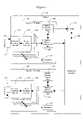
- FIG. 4shows the primary components of the inbound routing module (IRM) 200 of the present invention.
- the request queue 250examines each Fibre Channel frame header received from the Memory Controller Module 156 and forms a routing request, which contains the information required for routing the frame including the source port 112 and the D_ID for the frame.
- the request queue 250also arbitrates routing requests from the four ports 110 associated with the PPD 130 .
- the primary router 280uses the source port 112 and the D_ID found in the routing request to determine the appropriate switch destination address for that D_ID. This determination takes into account a variety of zoning rules.
- the primary router 280also determines an out-of-band priority designation that is used in the preferred embodiment to associate the frame with a virtual channel 106 across the output port 114 .
- the ISL group router 400examines the routing result created by the primary router 280 to determine if the chosen destination port is an ISL group 108 . If so, the ISL group router 400 determines which of the links 104 in the ISL group 108 will carry the frame to the other switch 100 . It then converts the destination port identifying the ISL group 108 received from primary router 280 to a switch destination address identifying an E_Port for a single ISL 104 within the group 108 .
- the priority combiner 500examines an in-band priority designation and an out-of-band priority designation made by the primary router 280 , and assigns the actual priority level for the routing decision.
- the output sorter 600uses the source port found in the routing result and delivers each routing result to the correct MCM 156 .
- the output from this component 600serves as the output of the entire IRM 200 .
- the MCM 156then stores the routing results in its queues as maintained by queue control module 158 .
- the MCM 156modifies the frame's header and inserts the frame's source part, destination port, priority, and routing reason code.
- the fabric interface module 160uses this information to segment the frames into cells 168 that can be switched across the crossbar 140 .
- the S_ID and D_IDare designated using standard, 24 bit Fibre Channel switch fabric addressing. These addresses are assigned using two different addressing modes: auto discovery addressing and fixed addressing. In auto discovery mode, new devices added to Fibre Channel loop automatically negotiate for the first available port address or Port_ID. In fixed addressing, the administrator for a device selects a port address for the device. In either mode, all devices on a single loop share a Domain_ID and an Area_ID. Although the Fibre Channel specifications describe both types of addressing, all known applications use auto discovery addressing.
- the present inventiontreats these two different addressing schemes differently, as shown in FIG. 5 .
- the Port_IDis not fixed and therefore all routing is done to the loop as a whole.
- the present inventiontreats the Domain_ID as a “region” address 202 , and treats the Area_ID as the “port” address 204 . Since the loop protocol handles its own routing, the IRM 200 ignores the Port_ID for auto discovery addressing. If fixed addressing is used, the true Port_ID (bits 7 - 0 of the Fibre Channel address) is considered the port address, with the Domain_ID and the Area ID being considered the region address.
- a regionis a set of 256 port addresses that share a region address. A region corresponds roughly to a Fibre Channel domain.
- the two addressing modesmay be mixed in a single switch 100 .
- the fabric 101may primarily use auto discovery addressing, but the user may desire to view a loop or a virtual adapter as a fixed addressing region so that the destination devices in the loop or virtual adapter can be independently prioritized and/or zoned based on their Port_ID.
- the inbound routing module 200has two ways of viewing regions, the lumped region view and the split region view.
- the IRM 200sees the region as a single entity.
- the switch 100When making routing and zoning decisions, the switch 100 considers only the region address 202 , and not the port address 204 .
- the split region viewthe IRM 200 sees the individual ports within the region.
- the switch 100When making routing and zoning decisions in the split region view, the switch 100 considers both the region address 202 and port address 204 .
- the split region viewis required for regions that are served by switch 100 , and for regions served by other switches that require routing or hard zoning based on port address. For other regions, the lumped region view is generally sufficient.
- the IRM 200supports all of the legal 239 regions (there are 239 valid Domain IDs). For 32 of the 239 regions, the IRM can use the split region view, viewing the ports within those regions individually for purposes of routing, prioritization, and hard zoning. For the other regions, the IRM uses the lumped region view. For fabrics that use fixed addressing (no known fabrics fall into this category), the IRM supports only 32 regions, and all of the regions use the split region view.
- IRM 200determines the frame's physical destination, which may be one of 512 Fibre Channel ports 110 or one of microprocessors 124 found on the I/O boards 120 , 122 .
- the IRM 200also recognizes intermediate logical destinations relating to internal multicasts groups (eight per I/O board 120 , 122 ) or one of eight ISL groups 108 . These intermediate logical destinations are later mapped to the switch destination address of a physical destination.
- the present inventionuses a ten bit address to define the switch destination address 206 , which can address physical ports 110 , multicast groups, ISL groups 108 , and microprocessor directed communication.
- the switch destination address 206is the address used by the switch 100 for internal routing. Addresses 208 for actual physical ports always have a 0 in the most significant bit. Multicast group addresses 210 start “10” in their most significant bits, while ISL group addresses 212 start “110,” and microprocessor addresses 214 start “11100.”
- Each of the address formats in FIG. 6can be easily changed to accommodate different numbers of physical ports 110 , multicast groups, ISL groups, or microprocessors 124 .
- the switch destination addresses 206could have more than ten bits, which would allow physical port address 208 to have a larger address range.
- the ISL group addresses 212 in FIG. 6show only three bits being used to select an ISL group, all six available bits could be used. This would allow a total of one hundred twenty-eight different ISL group addresses 212 even without expanding the size of the switch destination addresses 206 .
- the memory control module 156provides the request queue 250 with header information and a buffer memory location for each new frame that enters memory 154 .
- the preferred embodimentpresents this information through eight separate inputs, one memory location input and one header input for each of the four ports 110 associated with PPD 130 .
- An arbiter within request queue 250is able to arbitrate routing requests from the four ports 110 .
- the primary purpose of the request queue 250is to examine the received frame header and extract a routing request 260 for each frame.
- the routing request 260is fifty-two bits in length and contains the information shown in Table 1.
- the request queue 250writes the requests 260 , one at a time, into a buffer or FIFO 270 .
- the request FIFO 270is big enough to hold four hundred routing requests 260 , one hundred for each port 110 .
- a commandis sent to the request queue 250 to stop sending routing requests from the FIFO 270 to the primary router 280 .
- Routing requests 260accumulate in the FIFO 270 until the primary router 280 and ISL group router 400 are configured. While the request FIFO 270 holds routing requests 260 , frames accumulate in the credit memory 154 .
- the requests 260 in the FIFO 270are again made available to the primary router 280 .
- the request FIFO 270may also need to be stopped when the processor 124 reads the contents of the routing tables of primary router 280 , at least in cases where the routing tables are implemented using single ported memory.
- the request queue 250also has the ability to purge stale routing requests 260 for a port 110 from the FIFO 270 . In the preferred embodiment, this is accomplished by setting a bit in a register. When this purge enable bit is set, the request queue 250 will create a special purge routing request and add it to the request FIFO 270 .
- This purge request 260contains the two bit source port number, a unique, unused SOF type (“1110”), and port purge compare value (the four least significant bits of the D_ID). All other bits in the purge request are set to zero.
- the IRM 200will discard all routing requests for the designated port 110 while the purge enable bit is set until the purge routing request that matches the purge compare value is read out of the request queue FIFO 270 . At this point, the IRM 200 will discard the purge routing request and set the purge enable bit to zero. Routing requests 260 will resume being sent to the primary router 280 .
- a new “purge routing request”will be written into the FIFO 270 .
- One possibility for thisis if a link reset occurs multiple times while the IRM 200 is still disabled. While the IRM 200 is disabled, the processor 124 may change the purge compare value while the purge enable bit is set, but may only do so up to the value “1111”. This will ensure that the FIFO 270 will not overflow and that the IRM 200 will not stop purging on the incorrect “purge routing request”.
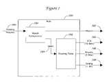
- the primary router 280receives routing requests 260 and then uses a plurality of routing rules 290 to determine the correct routing for the frame.
- the primary router 280functions by simultaneously applying different routing rules 290 to the routing request 260 .
- a match comparison component 292examines the routing request 260 to see if the D_ID within the request 260 matches the addresses that are relevant to the rule 290 .
- the match comparison component 292also determines an index 294 that is used to look up routing results for the request 260 in a routing table 296 .
- Each rule 290produces for its result a match indicator 282 that tells whether the rule 290 is applicable to the routing request 260 , as well as a switch destination address 284 , an out-of-band priority designation 286 , and a zoning indicator 288 . All of the rules 290 function in parallel, so as to speed up the routing determination.
- a selector 380(shown in FIG. 8 ) is then responsible for selecting the appropriate result from these rules 290 .
- the priority for a routed frameis used to associate the frame with one of eight virtual channels 106 across a switch port 110 .
- the priority fieldsare therefore only three bits long.
- in-band priorityis a priority based upon the content of the Fibre Channel frame, while out-of-band priority is based upon a routing determination using routing tables in the primary router 280 .
- the in-band priorityis taken from three bits within the Fibre Channel header, such as the bit 17 from the F_CTL (or frame control field) and bits 30 - 31 in the CS_CTL (or class specific control field).
- the in-band prioritycan be partially randomized.
- One way to do sois to based the in-band priority on the least significant bits of the assigned switch destination address 206 . For instance, if either bit 17 from F_CTL or bit 31 of CS_CTL were set to zero, the in-band priority could be 0 plus the two least significant bits of the switch destination address 206 . If both bit 17 from F_CTL and bit 31 of CS_CTL were set to one, the in-band priority would be 1 plus the two least significant bits of the switch destination address 206 .
- Some of the routing tables used by the rules 320 - 370will contain an out-of-band priority enable bit. This bit indicates whether the inbound routing module 200 is to assign out-of-band priority or in-band priority to the routed frames. If the out-of-band priority enable bit is zero, the frame will be assigned in-band priority, otherwise the frame will use out-of-band priority. The priority will be assigned to a known level (i.e., six or seven) for any frame that is sent to the violation switch destination address.
- the routing tablesmay also include a zoning indicator that confirms that the source port is allowed to communicate with the destination port according to the current zoning rules.
- the zoning indicatoruses a single bit to establish permission for a source to communicate with a destination, with the bit being set to one to indicate permission.
- multiple zoning bitsare associated with a single source-destination pair, with each bit being associated with a different Fibre Channel frame type (such as SCSI-3 or FICON).
- the routing tablesmay also contain a destination enable bit to indicate whether a particular destination is present and able to accept frames. If this bit is zero, the destination is not present or cannot accept frames. When combined with the zoning indicator, this allows the present invention to distinguish between zoning errors (the destination is present, but the source is not zoned to communicate with the destination) and destination not present errors. In both cases, the primary router 280 sends frames with these errors to the violation destination along with an error code indicating the source of the error. Frames received that are shorter than the Fibre Channel definition of nine words are automatically routed to the violation register with a reason code of “short frame received”.
- the primary components of the primary router 280are shown in FIG. 8 . These components are described in detail below.
- the type rule 310does not route routing requests 260 . Rather, this rule 310 transforms the type field found in the routing request 260 into a format that the primary router 280 can use. Although the routing request's eight-bit type field has 256 possible values, the primary router 280 only supports eight logical protocols.
- the type rule 310converts the routing request's eight-bit type field and one-bit type field valid indicator into a three-bit protocol index 312 . If the type field valid indicator shows that the type field in the routing request 260 is not valid, the type rule sets the protocol index 312 to seven.
- the type rule 310examines the type field from the routing request 260 , and assigns one of six programmable types to this Fibre Channel frame by setting the protocol index 312 to a number between zero and five. If the type field matches multiple programmable values, the type rule chooses the lowest matching protocol index 312 . A protocol index value of six indicates that the type field of the routing request 260 did not match any of the six programmable types. The protocol index 312 is then used by the other rules 320 - 370 to make protocol-based routing and zoning decisions.
- split regionmeans that the IRM 200 bases its routing on the port address 204 found in the D_ID. This is in contrast to the lumped region view of the D_ID, which routes according to the region address 202 only. Of the possible 239 regions, a maximum of thirty-two are routed according to the split region routing rules 320 . Each region is handled by a different rule 320 meaning that there are a total of thirty-two split region routing rules 320 .
- each split region routing rule 320identifies routing requests for its region using a register specially configured for that rule.
- This registerhas an addressing mode 322 , region identifier 324 , and source port mask 326 .
- the addressing mode 322is a single bit that communicates whether auto discovery addressing or fixed addressing is being used in the rule's region.
- the region identifier 324specifies the region that is applicable to the rule 320 .
- the identifieris sixteen bits long, but only the most significant eight bits are used in auto discovery addressing. Together, the region identifier 324 and the address mode identifier 322 can determine whether the region address 202 in the routing request 260 matches the region for that rule 320 .
- the address mode identifier 322is also used to identify the port address 204 for that D_ID.
- the source port mask 326indicates if the source port 112 is allowed to use this split region routing rule 320 .
- the mask 326is four bits long, one bit for each port in the PPD 130 . Setting the correct bit in this mask 326 allows the processor 124 to disable the use of this rule 320 with the ports 110 on the PPD 130 . If the source port mask 326 indicates that the rule 320 is disabled for the source port 112 indicated in the routing request 260 , the primary router 280 will attempt to match the routing requests 260 to some other rule.
- a rule 320determines that a routing request 260 belongs to its region and the source port 112 is allowed to use this rule 320 , the rule 320 uses the port address 204 of the D_ID as an index to a region routing table 328 .
- Each rule 320contains its own routing table 328 , meaning that the routing table 328 applies only to a single region address 202 .
- the routing table 328is configurable by the processor 124 , and contains two hundred fifty-six entries.
- Each entry in the routing tablecontains the switch destination address 206 (with all ports 110 in the PPD 130 using the same switch destination address 206 ), and four separate entries (one for each port on the PPD 130 ) of the following fields: a three-bit priority field, a one-bit destination enable bit, a one-bit out-of-band priority enable bit, and an eight-bit zoning field.
- the priority fieldspecifies the out-of-band priority for this combination of source port 112 and D_ID
- the destination enable bitdetermines whether this destination is enabled for this source port 112
- the out-of-band priority bitchooses between in-band or out-of-band priority
- the zoning fieldindicates whether the zoning rules allow this source port 112 to communicate to this D_ID for the frame type.
- the lumped region routing rule 330routes requests for frames that are intended to flow from a source port 112 to destination port 114 using the lumped region view. Since all port addresses 204 within a region are routed identically, there is no need for a separate routing table for each region address 202 . Rather, the lumped region routing rule 330 uses a single routing table 332 for all regions, with the region address 202 acting as the index to the table 332 . Much like the thirty-two split region routing tables 328 , each entry in the lumped region routing table 332 contains one switch destination address 206 , and four priority, destination enable, and zoning fields (one for each port 110 on the PPD 130 ).
- the lumped region routing table 332contains only 256 entries, meaning that the lumped region routing rule 330 supports only 256 different regions. Consequently, the rule 330 in this form is useful only for auto discovery addressing mode since only 256 different region addresses 202 exist in this mode. To support fixed addressing mode, which uses a sixteen-bit region address 202 , the lumped region routing table would need to have over thirty-two thousand entries.
- the well-known address routing rule 340identifies and routes routing requests for frames that are intended to flow from source port 112 to a well-known address destinations as defined by the Fibre Channel protocol.
- the single well-known address routing rule 340handles frames destined for all fifteen well-known addresses in the range 0 ⁇ FFFFF0 through 0 ⁇ FFFFFE.
- the well-known address routing ruleidentifies routing requests for frames destined for well-known addresses by comparing bits 4 - 23 in each routing request's D_ID to 0 ⁇ FFFFF.
- the result selector 380gives preference to the broadcast routing rule 370 over the well-known address routing rule 340 , ensuring that the well-known address routing rule's routing result is ignored when the routing request's D_ID is 0 ⁇ FFFFFF (indicating broadcast).
- the rule 340determines that a routing request is destined for a well-known address, it uses the four least significant bits in the routing request's D_ID as an index to a processor-configurable, fifteen-entry, well known address routing table 342 .
- This tablecontains the switch destination address 206 , destination enable bits, and the zoning indicators for each well-known address.
- This routing table 342does not contain priority 10 fields, as the well-known address routing rule 340 assigns all frames to fixed out-of-band priority level, such as priority level six or seven.
- the domain controller routing rule 350identifies and routes routing requests for frames that are intended to flow from a source port 112 to a domain controller destination.
- a single domain controller routing rule 350handles routing requests for frames destined for all 256 domain controller addresses in the range 0 ⁇ FFFC00 through 0 ⁇ FFFCFF.
- the domain controller routing rule 350identifies frames destined for domain controllers by comparing bits 8 - 23 of each routing request's D_ID to 0 ⁇ FFFC.
- the rule 350determines that a routing request 260 is destined for a domain controller address, it uses bits 0 - 7 of the routing request's D_ID as an index to a processor-configurable, two hundred fifty-six entry domain controller routing table 352 , which contains the switch destination address and zoning indicator for that domain controller. Much like the well-known address routing rule 340 , the domain controller routing table 352 does not contain priority information, since the domain controller routing rule 350 assigns all frames to a single, predetermined out-of-band priority level such as six or seven.
- the multicast routing rule 360identifies and routes routing requests for frames that are intended to flow from a source port 112 to multiple destination ports 114 .
- a single multicast routing rule 360handles routing requests 260 for frames destined for all 256 multicast group addresses in the range 0 ⁇ FFFB00 through 0 ⁇ FFFBFF.
- the multicast routing rule 360identifies routing requests for frames destined for Fibre Channel multicast groups by comparing bits 8 - 23 of the frame's D_ID to 0 ⁇ FFFB.
- the rule 360determines that a routing request 260 is destined for a Fibre Channel multicast group address, it uses bits 0 - 7 of the routing request's D_ID as an index to a processor-configurable, two hundred fifty-six entry multicast group routing table 362 .
- This table 362contains the switch destination address and zoning indicator for that Fibre Channel multicast group.
- the switch destination addresses in the multicast group routing tableare multicast switch destination addresses 210 .
- Each of the 256 multicast switch destination addresses 210identifies one of 256 internal logical multicast groups.
- the IRM 200 , MCM 156 , and FIM 160cooperate to send frames for that group to a subset of the microprocessors 124 that control the I/O boards 120 , 122 .
- Those microprocessors 124replicate the frames to the Fibre Channel ports 110 on their I/O boards 120 , 122 .
- the broadcast routing rule 370identifies and routes routing requests 260 for frames that are intended to flow from a source port 112 to multiple Fibre Channel destination ports 114 .
- the broadcast routing ruleis unique because the switch destination address 206 assigned to broadcast frames depends on the routing request's protocol index 312 , not just the on the D_ID in the routing request 260 .
- the broadcast routing rule 370identifies routing requests 260 for broadcast frames by comparing the routing request's D_ID to 0 ⁇ FFFFFF.
- the rule 370uses the routing request's protocol index 312 as an index to a processor-configurable, eight-entry broadcast routing table 372 , which contains the broadcast switch destination address 206 and zoning for that protocol index 312 .
- the switch destination addresses in the broadcast routing table 372are multicast switch destination addresses 210 .
- the PPD 130uses its multicast mechanism to replicate broadcast frames.
- the broadcast routing rule 370assigns all frames to set out-of-band priority level.
- the well-known address routing rule 340 , the domain controller routing rule 350 , the multicast routing rule 360 , and the broadcast routing rule 370all assign their frames to the same priority level.
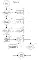
- the result selector 380examines the outputs of all of the routing rules 320 - 370 , and chooses a switch destination address 206 , out-of-band priority, and zoning indicator for each routing request according to the rules set forth in FIG. 9 .
- the first step 382is to determine if the split region routing rules 320 indicated a source port mask 326 violation. If so, the result selector 380 assigns the routing result's switch destination address to the violation switch destination address 206 selected by the processor 124 , and assigns a predetermined out-of-band priority level and a zoning indicator of one as seen in step 384 .
- the routing selector 380determines if the routing request's SOF type is not supported by the switch 100 at step 386 . For example, switches 100 often do not support Class 1 or Class 4 Fibre Channel frames. If the frame is not supported, the result selector 380 assigns the routing result's switch destination address to the violation switch destination address, and assigns a predetermined out-of-band priority level and a zoning indicator of one, as indicated in step 388 .
- step 390determines if the routing request 260 matches exactly one routing rule 320 - 370 . If so, the result selector 380 uses the switch destination address 206 , out-of-band priority, and zoning indicator from the matching rule 320 - 370 in step 392 . If the routing request 260 matches more than one routing rule 320 - 370 , the result selector 380 applies the following priority list in step 394 (from highest priority to lowest):
- the result selector 380After choosing the switch destination address 206 , out-of-band priority, and zoning indicator, the result selector 380 examines the zoning indicator in step 398 . If the zoning indicator is zero, this means there is a zoning violation. At step 399 , the result selector 380 changes the switch destination address to the violation switch destination address and changes the out-of-band priority to a predetermined level.
- the output of the result selector 380is the routing result's switch destination address 302 , an out-of-band priority 304 .
- the result selector 380also creates the routing reason code 306 , according to a predefined definition.
- the output of the result selector 380is the output of the primary router 280 , which is then submitted to the ISL group router 400 .
- the ISL group router 400helps balance the traffic across the various interswitch links 104 in the ISL group 108 (load balancing), while ensuring that all frames belonging to a single exchange are sent over a single interswitch link 104 .
- the ISL group router 400supports eight different ISL groups 108 , with an unlimited number of physical interswitch links 104 in each group 108 . Other embodiments could easily support thirty-two or even one hundred twenty-eight ISL groups 108 without any change in the size or apportioning of the switch destination addresses 206 .
- the processor 124programs the primary router 280 to recognize routing requests 260 for frames that should travel through one of the eight ISL groups 108 , and to map each of those routing requests to an ISL group switch destination address 212 . Any number of primary router entries can point to one of the ISL groups 108 .
- An ISL group switch destination address 212identifies which of the eight ISL groups 108 should carry the frame out of the switch 100 .
- the ISL group router 400balances traffic across the links in an ISL group 108 based on the traffic's source port 112 .
- Each IRM 200serves four source ports 110 , so every routing request 260 comes from one of four possible sources.
- the primary router 280tags a routing result with an ISL group switch destination address 212
- the ISL group router 400chooses a new ISL or E_Port switch destination address 208 for the routing result based on its source port 112 .
- the preferred embodimentuses a simple mapping table that directly assigns a specific ISL port address 208 for each possible source port/ISL group pairs.
- Fibre Channel S_ID, D_ID, OX_ID, or any combination of these elementscould be used as a key to a hash function that would be used to select a physical port switch destination address 208 for a particular ISL group (or for an ISL group/source port 112 combination). It would also be possible to subject these elements to a mask that would allow the processor 124 to set certain bits in these elements as “don't care” or “ignored” bits.
- One constant in all these techniquesis that all frames belonging to an individual exchange will be sent over the same physical interswitch link 104 .
- the processor 124configures the mapping between source port/ISL group pairs and the selected E_Port in the ISL group router 400 .
- the processor 124For each of the eight ISL groups 108 , the processor 124 provides four switch destination addresses 208 , one for routing requests from each source port 112 . Each of these addresses is the switch destination address 208 of a destination E_Port.
- the processor 124can choose an ISL 104 for each source port/ISL group combination.
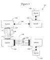
- FIG. 10shows a block diagram for the ISL group router 400 .
- the ISL group detector 410reads the switch destination address output 302 from the primary router 280 .
- the switch destination address 212is an ISL group 108 .
- ISL group detector 410need only look at the three most significant bits in address 302 to make its determination.
- the ISL group address redirector 420reads three bits (bits 6:4 in the preferred embodiment) from the switch destination address 302 that distinguish between the eight possible ISL groups 108 .
- the redirector 420combines this information with source port information from the routing request 260 to determine a new switch destination address 430 for an individual ISL 104 using mapping table 440 .
- a selector 450under the control of the ISL group detector 410 then chooses between the switch destination address 302 created by the primary router 280 and the switch destination address 430 created by the redirector 420 .
- the ISL group router 400does not alter the priority or zoning that was assigned to the frame by the primary router 280 .
- the priority combiner 500examines each routing result's switch destination address 302 , in-band priority level, and out-of-band priority level 304 , and assigns a single final priority level. If out-of-band priority has been enabled, either by having the bit set in the routing table or by the hardware forcing a priority level due to an error, the final priority level will be the out-of-band priority level 304 . If out-of-band priority 384 is not enabled, the final priority level will be the in-band priority level.
- the output sorter 600is responsible for routing the routing result from the rest of the inbound routing module 200 and delivering it to the MCM 156 for the input port 112 .
- the routing result delivered to the MCM 156contains the following elements: i) the switch destination address 206 for the output port 114 , ii) the three-bit final priority level, iii) a seven-bit reason code, which indicates which indicates why the IRM 200 routed the frame to its destination, iv) the frame's location in credit memory 154 , taken directly from the routing request 260 , and v) the frame's one-bit CRC regeneration flag, also taken directly from the routing request.
Landscapes
- Engineering & Computer Science (AREA)
- Computer Networks & Wireless Communication (AREA)
- Signal Processing (AREA)
- Data Exchanges In Wide-Area Networks (AREA)
Abstract
Description
| TABLE 1 | |||
| Length | |||
| (in bits) | Source | ||
| 2 | Source | MCM | 156 |
| 4 | SOF Type | Frame Header | |
| 24 | D_ID | Frame Header | |
| 8 | Frame's Type | Frame Header | |
| 1 | Type Field Valid | ||
| Indicator | |||
| 3 | In-Band Priority | Derived from the | |
| Header | |||
| 9 | MCM | 156 | |
| 1 | CRC Regeneration | MCM 156 (set when change | |
| made to frame header) | |||
| 2 | Source | MCM | 156 |
- the split region routing rules320 (with rule zero having the highest precedence),
- the
broadcast routing rule 370, - the well-known
address routing rule 340, domaincontroller routing rule 350, and multicast routing rule360 (which are mutually exclusive), and - the lumped region routing rule (every frame matches this rule).
The highest priority rule then determines theswitch destination address 206, out-of-band priority, and zoning indicator instep 396.
Claims (8)
Priority Applications (1)
| Application Number | Priority Date | Filing Date | Title |
|---|---|---|---|
| US10/873,547US7623519B2 (en) | 2004-06-21 | 2004-06-21 | Rule based routing in a switch |
Applications Claiming Priority (1)
| Application Number | Priority Date | Filing Date | Title |
|---|---|---|---|
| US10/873,547US7623519B2 (en) | 2004-06-21 | 2004-06-21 | Rule based routing in a switch |
Publications (2)
| Publication Number | Publication Date |
|---|---|
| US20050281196A1 US20050281196A1 (en) | 2005-12-22 |
| US7623519B2true US7623519B2 (en) | 2009-11-24 |
Family
ID=35480452
Family Applications (1)
| Application Number | Title | Priority Date | Filing Date |
|---|---|---|---|
| US10/873,547Expired - Fee RelatedUS7623519B2 (en) | 2004-06-21 | 2004-06-21 | Rule based routing in a switch |
Country Status (1)
| Country | Link |
|---|---|
| US (1) | US7623519B2 (en) |
Cited By (10)
| Publication number | Priority date | Publication date | Assignee | Title |
|---|---|---|---|---|
| US20080263239A1 (en)* | 2007-04-19 | 2008-10-23 | Hewlett-Packard Development Company, L.P. | Priority Selection Circuit |
| US7738371B1 (en)* | 2008-08-29 | 2010-06-15 | Qlogic, Corporation | Method and system for routing network packets |
| US7876752B1 (en) | 2008-08-29 | 2011-01-25 | Qlogic, Corporation | Method and system for partition based network routing |
| US20110032947A1 (en)* | 2009-08-08 | 2011-02-10 | Chris Michael Brueggen | Resource arbitration |
| US20110235525A1 (en)* | 2010-03-24 | 2011-09-29 | Fujitsu Limited | Monitoring apparatus, monitoring method, and monitoring program |
| US9071558B1 (en)* | 2009-03-24 | 2015-06-30 | Qlogic Corporation | Method and system for extended port addressing |
| US20160072696A1 (en)* | 2014-09-05 | 2016-03-10 | Telefonaktiebolaget L M Ericsson (Publ) | Forwarding table precedence in sdn |
| US9864716B2 (en) | 2015-05-20 | 2018-01-09 | International Business Machines Corporation | Receiving buffer credits by a plurality of channels of one or more host computational devices for transmitting data to a control unit |
| US9892065B2 (en) | 2015-05-20 | 2018-02-13 | International Business Machines Corporation | Adjustments of buffer credits for optimizing the number of retry operations and transfer ready operations |
| US10061734B2 (en) | 2015-05-20 | 2018-08-28 | International Business Machines Corporation | Adjustment of buffer credits and other parameters in a startup phase of communications between a plurality of channels and a control unit |
Families Citing this family (95)
| Publication number | Priority date | Publication date | Assignee | Title |
|---|---|---|---|---|
| US8798043B2 (en)* | 2002-06-28 | 2014-08-05 | Brocade Communications Systems, Inc. | Apparatus and method for routing traffic in multi-link switch |
| US7443799B2 (en) | 2003-10-31 | 2008-10-28 | Brocade Communication Systems, Inc. | Load balancing in core-edge configurations |
| US7619974B2 (en)* | 2003-10-31 | 2009-11-17 | Brocade Communication Systems, Inc. | Frame traffic balancing across trunk groups |
| US7711796B2 (en) | 2006-06-12 | 2010-05-04 | Icontrol Networks, Inc. | Gateway registry methods and systems |
| JP2007529826A (en) | 2004-03-16 | 2007-10-25 | アイコントロール ネットワークス, インコーポレイテッド | Object management network |
| US11277465B2 (en) | 2004-03-16 | 2022-03-15 | Icontrol Networks, Inc. | Generating risk profile using data of home monitoring and security system |
| US10522026B2 (en) | 2008-08-11 | 2019-12-31 | Icontrol Networks, Inc. | Automation system user interface with three-dimensional display |
| US11201755B2 (en) | 2004-03-16 | 2021-12-14 | Icontrol Networks, Inc. | Premises system management using status signal |
| US10348575B2 (en) | 2013-06-27 | 2019-07-09 | Icontrol Networks, Inc. | Control system user interface |
| US10062273B2 (en) | 2010-09-28 | 2018-08-28 | Icontrol Networks, Inc. | Integrated security system with parallel processing architecture |
| US11368429B2 (en) | 2004-03-16 | 2022-06-21 | Icontrol Networks, Inc. | Premises management configuration and control |
| US10237237B2 (en) | 2007-06-12 | 2019-03-19 | Icontrol Networks, Inc. | Communication protocols in integrated systems |
| US20090077623A1 (en) | 2005-03-16 | 2009-03-19 | Marc Baum | Security Network Integrating Security System and Network Devices |
| US11677577B2 (en) | 2004-03-16 | 2023-06-13 | Icontrol Networks, Inc. | Premises system management using status signal |
| US11316958B2 (en) | 2008-08-11 | 2022-04-26 | Icontrol Networks, Inc. | Virtual device systems and methods |
| US11489812B2 (en) | 2004-03-16 | 2022-11-01 | Icontrol Networks, Inc. | Forming a security network including integrated security system components and network devices |
| US10721087B2 (en) | 2005-03-16 | 2020-07-21 | Icontrol Networks, Inc. | Method for networked touchscreen with integrated interfaces |
| US10156959B2 (en) | 2005-03-16 | 2018-12-18 | Icontrol Networks, Inc. | Cross-client sensor user interface in an integrated security network |
| US11244545B2 (en) | 2004-03-16 | 2022-02-08 | Icontrol Networks, Inc. | Cross-client sensor user interface in an integrated security network |
| US20170118037A1 (en) | 2008-08-11 | 2017-04-27 | Icontrol Networks, Inc. | Integrated cloud system for premises automation |
| US12063220B2 (en) | 2004-03-16 | 2024-08-13 | Icontrol Networks, Inc. | Communication protocols in integrated systems |
| US11343380B2 (en) | 2004-03-16 | 2022-05-24 | Icontrol Networks, Inc. | Premises system automation |
| US9141276B2 (en) | 2005-03-16 | 2015-09-22 | Icontrol Networks, Inc. | Integrated interface for mobile device |
| US10142392B2 (en) | 2007-01-24 | 2018-11-27 | Icontrol Networks, Inc. | Methods and systems for improved system performance |
| US9729342B2 (en) | 2010-12-20 | 2017-08-08 | Icontrol Networks, Inc. | Defining and implementing sensor triggered response rules |
| US11582065B2 (en) | 2007-06-12 | 2023-02-14 | Icontrol Networks, Inc. | Systems and methods for device communication |
| US11811845B2 (en) | 2004-03-16 | 2023-11-07 | Icontrol Networks, Inc. | Communication protocols over internet protocol (IP) networks |
| US10339791B2 (en) | 2007-06-12 | 2019-07-02 | Icontrol Networks, Inc. | Security network integrated with premise security system |
| US11916870B2 (en) | 2004-03-16 | 2024-02-27 | Icontrol Networks, Inc. | Gateway registry methods and systems |
| US20050281282A1 (en)* | 2004-06-21 | 2005-12-22 | Gonzalez Henry J | Internal messaging within a switch |
| US8700799B2 (en)* | 2004-11-12 | 2014-04-15 | Brocade Communications Systems, Inc. | Methods, devices and systems with improved zone merge operation by operating on a switch basis |
| US7701976B2 (en)* | 2004-12-22 | 2010-04-20 | Exar Corporation | Communications system with segmenting and framing of segments |
| US8116226B1 (en)* | 2005-01-28 | 2012-02-14 | PMC-Sierra, USA Inc. | Method and apparatus for broadcast primitive filtering in SAS |
| US10999254B2 (en) | 2005-03-16 | 2021-05-04 | Icontrol Networks, Inc. | System for data routing in networks |
| US11615697B2 (en) | 2005-03-16 | 2023-03-28 | Icontrol Networks, Inc. | Premise management systems and methods |
| US11700142B2 (en) | 2005-03-16 | 2023-07-11 | Icontrol Networks, Inc. | Security network integrating security system and network devices |
| US20120324566A1 (en) | 2005-03-16 | 2012-12-20 | Marc Baum | Takeover Processes In Security Network Integrated With Premise Security System |
| US20110128378A1 (en) | 2005-03-16 | 2011-06-02 | Reza Raji | Modular Electronic Display Platform |
| US11496568B2 (en) | 2005-03-16 | 2022-11-08 | Icontrol Networks, Inc. | Security system with networked touchscreen |
| US20170180198A1 (en) | 2008-08-11 | 2017-06-22 | Marc Baum | Forming a security network including integrated security system components |
| US8335231B2 (en)* | 2005-04-08 | 2012-12-18 | Cisco Technology, Inc. | Hardware based zoning in fibre channel networks |
| US7881325B2 (en)* | 2005-04-27 | 2011-02-01 | Cisco Technology, Inc. | Load balancing technique implemented in a storage area network |
| WO2006122366A1 (en)* | 2005-05-18 | 2006-11-23 | Ninety9.Com Pty Ltd | Dynamic address mapping |
| US7647434B2 (en)* | 2005-05-19 | 2010-01-12 | Cisco Technology, Inc. | Technique for in order delivery of traffic across a storage area network |
| WO2007055757A2 (en) | 2005-07-28 | 2007-05-18 | Riverbed Technology, Inc. | Serial clustering |
| US20070058620A1 (en)* | 2005-08-31 | 2007-03-15 | Mcdata Corporation | Management of a switch fabric through functionality conservation |
| US9143841B2 (en) | 2005-09-29 | 2015-09-22 | Brocade Communications Systems, Inc. | Federated management of intelligent service modules |
| US7953866B2 (en)* | 2006-03-22 | 2011-05-31 | Mcdata Corporation | Protocols for connecting intelligent service modules in a storage area network |
| US20070258443A1 (en)* | 2006-05-02 | 2007-11-08 | Mcdata Corporation | Switch hardware and architecture for a computer network |
| US10079839B1 (en) | 2007-06-12 | 2018-09-18 | Icontrol Networks, Inc. | Activation of gateway device |
| US12063221B2 (en) | 2006-06-12 | 2024-08-13 | Icontrol Networks, Inc. | Activation of gateway device |
| US11706279B2 (en) | 2007-01-24 | 2023-07-18 | Icontrol Networks, Inc. | Methods and systems for data communication |
| US7633385B2 (en) | 2007-02-28 | 2009-12-15 | Ucontrol, Inc. | Method and system for communicating with and controlling an alarm system from a remote server |
| US8451986B2 (en) | 2007-04-23 | 2013-05-28 | Icontrol Networks, Inc. | Method and system for automatically providing alternate network access for telecommunications |
| US12283172B2 (en) | 2007-06-12 | 2025-04-22 | Icontrol Networks, Inc. | Communication protocols in integrated systems |
| US12184443B2 (en) | 2007-06-12 | 2024-12-31 | Icontrol Networks, Inc. | Controlling data routing among networks |
| US11212192B2 (en) | 2007-06-12 | 2021-12-28 | Icontrol Networks, Inc. | Communication protocols in integrated systems |
| US11423756B2 (en) | 2007-06-12 | 2022-08-23 | Icontrol Networks, Inc. | Communication protocols in integrated systems |
| US12003387B2 (en) | 2012-06-27 | 2024-06-04 | Comcast Cable Communications, Llc | Control system user interface |
| US11218878B2 (en) | 2007-06-12 | 2022-01-04 | Icontrol Networks, Inc. | Communication protocols in integrated systems |
| US11646907B2 (en) | 2007-06-12 | 2023-05-09 | Icontrol Networks, Inc. | Communication protocols in integrated systems |
| US10523689B2 (en) | 2007-06-12 | 2019-12-31 | Icontrol Networks, Inc. | Communication protocols over internet protocol (IP) networks |
| US11601810B2 (en) | 2007-06-12 | 2023-03-07 | Icontrol Networks, Inc. | Communication protocols in integrated systems |
| US11316753B2 (en) | 2007-06-12 | 2022-04-26 | Icontrol Networks, Inc. | Communication protocols in integrated systems |
| US11237714B2 (en) | 2007-06-12 | 2022-02-01 | Control Networks, Inc. | Control system user interface |
| US11831462B2 (en) | 2007-08-24 | 2023-11-28 | Icontrol Networks, Inc. | Controlling data routing in premises management systems |
| US9342339B2 (en)* | 2007-11-07 | 2016-05-17 | Brocade Communications Systems, Inc. | Method and system for congestion management in a fibre channel network |
| US11916928B2 (en) | 2008-01-24 | 2024-02-27 | Icontrol Networks, Inc. | Communication protocols over internet protocol (IP) networks |
| JP5050978B2 (en)* | 2008-04-21 | 2012-10-17 | 富士通株式会社 | Transmission information transfer apparatus and method |
| US20170185278A1 (en) | 2008-08-11 | 2017-06-29 | Icontrol Networks, Inc. | Automation system user interface |
| US11258625B2 (en) | 2008-08-11 | 2022-02-22 | Icontrol Networks, Inc. | Mobile premises automation platform |
| US10530839B2 (en) | 2008-08-11 | 2020-01-07 | Icontrol Networks, Inc. | Integrated cloud system with lightweight gateway for premises automation |
| US11792036B2 (en) | 2008-08-11 | 2023-10-17 | Icontrol Networks, Inc. | Mobile premises automation platform |
| US11729255B2 (en) | 2008-08-11 | 2023-08-15 | Icontrol Networks, Inc. | Integrated cloud system with lightweight gateway for premises automation |
| US11758026B2 (en) | 2008-08-11 | 2023-09-12 | Icontrol Networks, Inc. | Virtual device systems and methods |
| US20160164923A1 (en)* | 2008-08-25 | 2016-06-09 | Paul J. Dawes | Method for data routing in networks |
| US20100124227A1 (en)* | 2008-11-19 | 2010-05-20 | General Electric Company | Systems and methods for electronically routing data |
| US8638211B2 (en) | 2009-04-30 | 2014-01-28 | Icontrol Networks, Inc. | Configurable controller and interface for home SMA, phone and multimedia |
| FR2955992B1 (en)* | 2010-01-29 | 2012-04-20 | Inst Nat Rech Inf Automat | MODULATING SWITCHING OR ROUTING DEVICE |
| FR2961048B1 (en)* | 2010-06-03 | 2013-04-26 | Arteris Inc | CHIP NETWORK WITH QUALITY-OF-SERVICE CHARACTERISTICS |
| US8836467B1 (en) | 2010-09-28 | 2014-09-16 | Icontrol Networks, Inc. | Method, system and apparatus for automated reporting of account and sensor zone information to a central station |
| US11750414B2 (en) | 2010-12-16 | 2023-09-05 | Icontrol Networks, Inc. | Bidirectional security sensor communication for a premises security system |
| US9147337B2 (en) | 2010-12-17 | 2015-09-29 | Icontrol Networks, Inc. | Method and system for logging security event data |
| US8929220B2 (en)* | 2012-08-24 | 2015-01-06 | Advanced Micro Devices, Inc. | Processing system using virtual network interface controller addressing as flow control metadata |
| US10375155B1 (en) | 2013-02-19 | 2019-08-06 | F5 Networks, Inc. | System and method for achieving hardware acceleration for asymmetric flow connections |
| US9787586B2 (en)* | 2013-10-24 | 2017-10-10 | University Of Houston System | Location-based network routing |
| US11146637B2 (en) | 2014-03-03 | 2021-10-12 | Icontrol Networks, Inc. | Media content management |
| US11405463B2 (en) | 2014-03-03 | 2022-08-02 | Icontrol Networks, Inc. | Media content management |
| US9491240B2 (en)* | 2014-06-27 | 2016-11-08 | International Business Machines Corporation | Maintenance of a fabric priority during synchronous copy operations |
| EP3238396A4 (en)* | 2014-12-27 | 2018-08-15 | Intel Corporation | Technologies for scalable local addressing in high-performance network fabrics |
| US10084859B2 (en)* | 2015-01-26 | 2018-09-25 | International Business Machines Corporation | Method to designate and implement new routing options for high priority data flows |
| US9985729B2 (en)* | 2016-02-23 | 2018-05-29 | International Business Machines Corporation | Management of frame priorities in fibre channel |
| TWI643508B (en)* | 2016-12-22 | 2018-12-01 | 張恭維 | Smart routing system for IoT smart devices |
| US11088967B2 (en)* | 2019-04-26 | 2021-08-10 | Intel Corporation | Shared resources for multiple communication traffics |
| CN120567761A (en)* | 2025-07-28 | 2025-08-29 | 合肥智芯半导体有限公司 | Intelligent communication system, communication method and device based on dynamic priority and vehicle |
Citations (35)
| Publication number | Priority date | Publication date | Assignee | Title |
|---|---|---|---|---|
| US4710868A (en) | 1984-06-29 | 1987-12-01 | International Business Machines Corporation | Interconnect scheme for shared memory local networks |
| US5455820A (en) | 1993-05-20 | 1995-10-03 | Nec Corporation | Output-buffer switch for asynchronous transfer mode |
| US5533201A (en) | 1994-03-07 | 1996-07-02 | Unisys Corporation | Method and apparatus for simultaneous interconnection of multiple requestors to multiple memories |
| US5771227A (en)* | 1995-03-08 | 1998-06-23 | International Business Machines Corporation | Method and system for routing massages in a multi-node data communication network |
| US5781549A (en) | 1996-02-23 | 1998-07-14 | Allied Telesyn International Corp. | Method and apparatus for switching data packets in a data network |
| EP0856969A1 (en) | 1997-01-31 | 1998-08-05 | Nec Corporation | Fibre channel fabric |
| US5844887A (en) | 1995-11-30 | 1998-12-01 | Scorpio Communications Ltd. | ATM switching fabric |
| US5974467A (en) | 1997-08-29 | 1999-10-26 | Extreme Networks | Protocol for communicating data between packet forwarding devices via an intermediate network interconnect device |
| US5983260A (en) | 1995-07-19 | 1999-11-09 | Fujitsu Network Communications, Inc. | Serial control and data interconnects for coupling an I/O module with a switch fabric in a switch |
| EP0959591A1 (en) | 1998-05-20 | 1999-11-24 | Nec Corporation | ATM switching module suited for system expansion without cell-loss |
| US5999527A (en) | 1996-02-02 | 1999-12-07 | Telefonaktiebolaget Lm Ericsson | Modular switch |
| US6067286A (en) | 1995-04-11 | 2000-05-23 | General Datacomm, Inc. | Data network switch with fault tolerance |
| EP1016980A2 (en) | 1998-12-22 | 2000-07-05 | Ncr International Inc. | Distributed multi-fabric interconnect |
| US6160813A (en) | 1997-03-21 | 2000-12-12 | Brocade Communications Systems, Inc. | Fibre channel switching system and method |
| US6185203B1 (en)* | 1997-02-18 | 2001-02-06 | Vixel Corporation | Fibre channel switching fabric |
| WO2001067672A2 (en) | 2000-03-07 | 2001-09-13 | Sun Microsystems, Inc. | Virtual channel flow control |
| US6307855B1 (en)* | 1997-07-09 | 2001-10-23 | Yoichi Hariguchi | Network routing table using content addressable memory |
| US6335992B1 (en) | 2000-02-15 | 2002-01-01 | Tellium, Inc. | Scalable optical cross-connect system and method transmitter/receiver protection |
| US6370145B1 (en) | 1997-08-22 | 2002-04-09 | Avici Systems | Internet switch router |
| US20020156918A1 (en) | 2001-04-23 | 2002-10-24 | Brocade Communications Systems, Inc. | Dynamic path selection with in-order delivery within sequence in a communication network |
| US20020176417A1 (en)* | 2001-04-18 | 2002-11-28 | Brocade Communications Systems, Inc. | Fibre channel zoning by device name in hardware |
| US20030026267A1 (en) | 2001-07-31 | 2003-02-06 | Oberman Stuart F. | Virtual channels in a network switch |
| WO2003017583A1 (en) | 2001-08-17 | 2003-02-27 | Mcdata Corporation | Route lookup caching for a fibre channel switch |
| WO2003017103A1 (en) | 2001-08-17 | 2003-02-27 | Mcdata Corporation | Compact, shared route lookup table for a fibre channel switch |
| US6600744B1 (en)* | 1999-03-23 | 2003-07-29 | Alcatel Canada Inc. | Method and apparatus for packet classification in a data communication system |
| US20030156586A1 (en)* | 2002-02-19 | 2003-08-21 | Broadcom Corporation | Method and apparatus for flexible frame processing and classification engine |
| US20030202474A1 (en) | 2002-04-29 | 2003-10-30 | Brocade Communications Systems, Inc. | Frame-pull flow control in a fibre channel network |
| US20040017771A1 (en) | 2002-07-29 | 2004-01-29 | Brocade Communications Systems, Inc. | Cascade credit sharing for fibre channel links |
| US20040024906A1 (en) | 2002-07-31 | 2004-02-05 | Brocade Communications Systems, Inc. | Load balancing in a network comprising communication paths having different bandwidths |
| US20040081096A1 (en) | 2002-10-28 | 2004-04-29 | Brocade Communications Systems, Inc. | Method and device for extending usable lengths of fibre channel links |
| US6765919B1 (en)* | 1998-10-23 | 2004-07-20 | Brocade Communications Systems, Inc. | Method and system for creating and implementing zones within a fibre channel system |
| US6819654B2 (en)* | 2001-09-25 | 2004-11-16 | Mcdata Corporation | Trunking inter-switch links |
| US20050100012A1 (en)* | 2003-11-12 | 2005-05-12 | Stefanos Kaxiras | Set-associative memory architecture for routing tables |
| US7336617B1 (en)* | 2003-08-01 | 2008-02-26 | Verizon Laboratories Inc. | Bit-field-encoded resource record for determining a transmission path in a communications network |
| US7369554B1 (en)* | 2000-12-22 | 2008-05-06 | Nortel Networks Limited | Method and apparatus for performing filter operations on data packets using an instruction |
- 2004
- 2004-06-21USUS10/873,547patent/US7623519B2/ennot_activeExpired - Fee Related
Patent Citations (36)
| Publication number | Priority date | Publication date | Assignee | Title |
|---|---|---|---|---|
| US4710868A (en) | 1984-06-29 | 1987-12-01 | International Business Machines Corporation | Interconnect scheme for shared memory local networks |
| US5455820A (en) | 1993-05-20 | 1995-10-03 | Nec Corporation | Output-buffer switch for asynchronous transfer mode |
| US5533201A (en) | 1994-03-07 | 1996-07-02 | Unisys Corporation | Method and apparatus for simultaneous interconnection of multiple requestors to multiple memories |
| US5771227A (en)* | 1995-03-08 | 1998-06-23 | International Business Machines Corporation | Method and system for routing massages in a multi-node data communication network |
| US6067286A (en) | 1995-04-11 | 2000-05-23 | General Datacomm, Inc. | Data network switch with fault tolerance |
| US5983260A (en) | 1995-07-19 | 1999-11-09 | Fujitsu Network Communications, Inc. | Serial control and data interconnects for coupling an I/O module with a switch fabric in a switch |
| US5844887A (en) | 1995-11-30 | 1998-12-01 | Scorpio Communications Ltd. | ATM switching fabric |
| US5999527A (en) | 1996-02-02 | 1999-12-07 | Telefonaktiebolaget Lm Ericsson | Modular switch |
| US5781549A (en) | 1996-02-23 | 1998-07-14 | Allied Telesyn International Corp. | Method and apparatus for switching data packets in a data network |
| EP0856969A1 (en) | 1997-01-31 | 1998-08-05 | Nec Corporation | Fibre channel fabric |
| US6185203B1 (en)* | 1997-02-18 | 2001-02-06 | Vixel Corporation | Fibre channel switching fabric |
| US6160813A (en) | 1997-03-21 | 2000-12-12 | Brocade Communications Systems, Inc. | Fibre channel switching system and method |
| US6307855B1 (en)* | 1997-07-09 | 2001-10-23 | Yoichi Hariguchi | Network routing table using content addressable memory |
| US6370145B1 (en) | 1997-08-22 | 2002-04-09 | Avici Systems | Internet switch router |
| US5974467A (en) | 1997-08-29 | 1999-10-26 | Extreme Networks | Protocol for communicating data between packet forwarding devices via an intermediate network interconnect device |
| EP0959591A1 (en) | 1998-05-20 | 1999-11-24 | Nec Corporation | ATM switching module suited for system expansion without cell-loss |
| US6765919B1 (en)* | 1998-10-23 | 2004-07-20 | Brocade Communications Systems, Inc. | Method and system for creating and implementing zones within a fibre channel system |
| EP1016980A2 (en) | 1998-12-22 | 2000-07-05 | Ncr International Inc. | Distributed multi-fabric interconnect |
| US6600744B1 (en)* | 1999-03-23 | 2003-07-29 | Alcatel Canada Inc. | Method and apparatus for packet classification in a data communication system |
| US6335992B1 (en) | 2000-02-15 | 2002-01-01 | Tellium, Inc. | Scalable optical cross-connect system and method transmitter/receiver protection |
| WO2001067672A2 (en) | 2000-03-07 | 2001-09-13 | Sun Microsystems, Inc. | Virtual channel flow control |
| US7369554B1 (en)* | 2000-12-22 | 2008-05-06 | Nortel Networks Limited | Method and apparatus for performing filter operations on data packets using an instruction |
| US20020176417A1 (en)* | 2001-04-18 | 2002-11-28 | Brocade Communications Systems, Inc. | Fibre channel zoning by device name in hardware |
| US7167472B2 (en)* | 2001-04-18 | 2007-01-23 | Brocade Communications Systems, Inc. | Fibre channel zoning by device name in hardware |
| US20020156918A1 (en) | 2001-04-23 | 2002-10-24 | Brocade Communications Systems, Inc. | Dynamic path selection with in-order delivery within sequence in a communication network |
| US20030026267A1 (en) | 2001-07-31 | 2003-02-06 | Oberman Stuart F. | Virtual channels in a network switch |
| WO2003017583A1 (en) | 2001-08-17 | 2003-02-27 | Mcdata Corporation | Route lookup caching for a fibre channel switch |
| WO2003017103A1 (en) | 2001-08-17 | 2003-02-27 | Mcdata Corporation | Compact, shared route lookup table for a fibre channel switch |
| US6819654B2 (en)* | 2001-09-25 | 2004-11-16 | Mcdata Corporation | Trunking inter-switch links |
| US20030156586A1 (en)* | 2002-02-19 | 2003-08-21 | Broadcom Corporation | Method and apparatus for flexible frame processing and classification engine |
| US20030202474A1 (en) | 2002-04-29 | 2003-10-30 | Brocade Communications Systems, Inc. | Frame-pull flow control in a fibre channel network |
| US20040017771A1 (en) | 2002-07-29 | 2004-01-29 | Brocade Communications Systems, Inc. | Cascade credit sharing for fibre channel links |
| US20040024906A1 (en) | 2002-07-31 | 2004-02-05 | Brocade Communications Systems, Inc. | Load balancing in a network comprising communication paths having different bandwidths |
| US20040081096A1 (en) | 2002-10-28 | 2004-04-29 | Brocade Communications Systems, Inc. | Method and device for extending usable lengths of fibre channel links |
| US7336617B1 (en)* | 2003-08-01 | 2008-02-26 | Verizon Laboratories Inc. | Bit-field-encoded resource record for determining a transmission path in a communications network |
| US20050100012A1 (en)* | 2003-11-12 | 2005-05-12 | Stefanos Kaxiras | Set-associative memory architecture for routing tables |
Non-Patent Citations (11)
| Title |
|---|
| Applied Micro Circuits Corporation, Cyclone (nPX8005) Switch Fabric, https://www.amcc.com/cardiff/docManagement/displayProduct Summary.jsp?prodld=nPX8005, Downloaded Feb. 16, 2005. |
| Erwin P. Rathgeb, Redundancy Concepts for a Large ATM Switching Node, Sep. 21, 1997, XVI World Telecom Congress Proceedings. |
| Gregory L. Frazier & Yuval Tamir, The Design & Implementation of a Multi-Queue Buffer for VLSI Communication Switches, Proceedings of the International Conference on Computer Design, Oct. 1989, pp. 466-471, IEEE, New York, NY. |
| Kenneth Y. Yun, A Terabit Multiservice Switch, IEEE Micro, Jan.-Feb. 2001, pp. 58-70. |
| Kohei Shiomoto, Masayuki Murata, Yuji Oie and Mideo Miyahaha, Performance Evaluation of Cell Bypass Queuing Discipline for Buffered Banyan Type ATM Switches, Proceedings INFOCOM '90, Feb. 25, 2005, pp. 677-685 vol. 2, IEEE, New York, NY. |
| M. Shreedhar & George Varghese, Efficient Fair Queuing Using Deficit Round-Robin, IEEE/ACM Transactions on Networking, Jun. 1996, pp. 375-385, vol. 4, No. 3. |
| Packet Switch Chips, Feb. 2, 2003, www.lightreading.com/document.asp?doc-id=25989&print=true, Downloaded Feb. 16, 2005. |
| Providing Reliable, High-Speed Operations in Large Sans, 2002 Brocade Communications Systems, Inc., Mar. 2002. |
| The Virtual Output Queue, http://ipoint.vlsi.uiuc.edu/abr/virtqueue.html, Downloaded Feb. 16, 2005. |
| Wolfgang Fischer, Oswald Fundneider, Ernst-Heinrich Goeldner & K.A. Lutz, A Scalable ATM Switching System Architecture, IEEE Journal on Selected Areas in Communications, Oct. 1991, pp. 1299-1307, vol. 9, No. 8, New York, NY. |
| Zoltan Meggyesi, "Fiber Channel Overview," 1994, Research Institute for Particle and Nuclear Physics, pp. 1-10.* |
Cited By (17)
| Publication number | Priority date | Publication date | Assignee | Title |
|---|---|---|---|---|
| US7817653B2 (en)* | 2007-04-19 | 2010-10-19 | Hewlett-Packard Development Company, L.P. | Priority selection circuit |
| US20080263239A1 (en)* | 2007-04-19 | 2008-10-23 | Hewlett-Packard Development Company, L.P. | Priority Selection Circuit |
| US7738371B1 (en)* | 2008-08-29 | 2010-06-15 | Qlogic, Corporation | Method and system for routing network packets |
| US7876752B1 (en) | 2008-08-29 | 2011-01-25 | Qlogic, Corporation | Method and system for partition based network routing |
| US9071558B1 (en)* | 2009-03-24 | 2015-06-30 | Qlogic Corporation | Method and system for extended port addressing |
| US20110032947A1 (en)* | 2009-08-08 | 2011-02-10 | Chris Michael Brueggen | Resource arbitration |
| US8085801B2 (en) | 2009-08-08 | 2011-12-27 | Hewlett-Packard Development Company, L.P. | Resource arbitration |
| US8743704B2 (en)* | 2010-03-24 | 2014-06-03 | Fujitsu Limited | Monitoring apparatus, monitoring method, and monitoring program |
| US20110235525A1 (en)* | 2010-03-24 | 2011-09-29 | Fujitsu Limited | Monitoring apparatus, monitoring method, and monitoring program |
| US20160072696A1 (en)* | 2014-09-05 | 2016-03-10 | Telefonaktiebolaget L M Ericsson (Publ) | Forwarding table precedence in sdn |
| US9692684B2 (en)* | 2014-09-05 | 2017-06-27 | Telefonaktiebolaget L M Ericsson (Publ) | Forwarding table precedence in SDN |
| US9864716B2 (en) | 2015-05-20 | 2018-01-09 | International Business Machines Corporation | Receiving buffer credits by a plurality of channels of one or more host computational devices for transmitting data to a control unit |
| US9892065B2 (en) | 2015-05-20 | 2018-02-13 | International Business Machines Corporation | Adjustments of buffer credits for optimizing the number of retry operations and transfer ready operations |
| US10061734B2 (en) | 2015-05-20 | 2018-08-28 | International Business Machines Corporation | Adjustment of buffer credits and other parameters in a startup phase of communications between a plurality of channels and a control unit |
| US10140236B2 (en) | 2015-05-20 | 2018-11-27 | International Business Machines Corporation | Receiving buffer credits by a plurality of channels of one or more host computational devices for transmitting data to a control unit |
| US10157150B2 (en) | 2015-05-20 | 2018-12-18 | International Business Machines Corporation | Adjustments of buffer credits for optimizing the number of retry operations and transfer ready operations |
| US10289591B2 (en) | 2015-05-20 | 2019-05-14 | International Business Machines Corporation | Adjustment of buffer credits and other parameters in a startup phase of communications between a plurality of channels and a control unit |
Also Published As
| Publication number | Publication date |
|---|---|
| US20050281196A1 (en) | 2005-12-22 |
Similar Documents
| Publication | Publication Date | Title |
|---|---|---|
| US7623519B2 (en) | Rule based routing in a switch | |
| US7042842B2 (en) | Fiber channel switch | |
| US7646767B2 (en) | Method and system for programmable data dependant network routing | |
| US7406092B2 (en) | Programmable pseudo virtual lanes for fibre channel systems | |
| US7990975B1 (en) | Method and system for using extended fabric features with fibre channel switch elements | |
| US7466700B2 (en) | LUN based hard zoning in fibre channel switches | |
| US7515537B2 (en) | Method and apparatus for rendering a cell-based switch useful for frame based protocols | |
| US6510135B1 (en) | Flow-level demultiplexing within routers | |
| US7894348B2 (en) | Method and system for congestion control in a fibre channel switch | |
| US8081650B2 (en) | Method and system for selecting virtual lanes in fibre channel switches | |
| US20060165111A1 (en) | Replication of multicast data packets in a multi-stage switching system | |
| US20070268903A1 (en) | System and Method for Assigning Packets to Output Queues | |
| US11171884B2 (en) | Efficient memory utilization and egress queue fairness | |
| US20100095025A1 (en) | Virtual channel remapping | |
| US7058053B1 (en) | Method and system to process a multicast request pertaining to a packet received at an interconnect device | |
| US20050281282A1 (en) | Internal messaging within a switch | |
| US8265072B2 (en) | Frame switching device | |
| US7580354B2 (en) | Multi-speed cut through operation in fibre channel switches | |
| US20060013135A1 (en) | Flow control in a switch | |
| US7460528B1 (en) | Processing data packets at a storage service module of a switch | |
| US20090296715A1 (en) | Method and system for programmable data dependant network routing | |
| US9172661B1 (en) | Method and system for using lane alignment markers | |
| US8116206B1 (en) | Method and system for routing frames in a network | |
| US7382776B1 (en) | Performing block storage virtualization at a switch | |
| US9426063B1 (en) | Systems and methods for routing by network devices |
Legal Events
| Date | Code | Title | Description |
|---|---|---|---|
| AS | Assignment | Owner name:COMPUTER NETWORK TECHNOLOGY CORPORATION, MINNESOTA Free format text:ASSIGNMENT OF ASSIGNORS INTEREST;ASSIGNORS:TORNETTA, ANTHONY G.;WORKMAN, JASON;PEARSON, JERELD W.;AND OTHERS;REEL/FRAME:015985/0492 Effective date:20041021 | |
| AS | Assignment | Owner name:MCDATA SERVICES CORPORATION, CALIFORNIA Free format text:MERGER;ASSIGNOR:COMPUTER NETWORK TECHNOLOGY CORPORATION;REEL/FRAME:021952/0245 Effective date:20050531 | |
| AS | Assignment | Owner name:BANK OF AMERICA, N.A. AS ADMINISTRATIVE AGENT, CAL Free format text:SECURITY AGREEMENT;ASSIGNORS:BROCADE COMMUNICATIONS SYSTEMS, INC.;FOUNDRY NETWORKS, INC.;INRANGE TECHNOLOGIES CORPORATION;AND OTHERS;REEL/FRAME:022012/0204 Effective date:20081218 Owner name:BANK OF AMERICA, N.A. AS ADMINISTRATIVE AGENT,CALI Free format text:SECURITY AGREEMENT;ASSIGNORS:BROCADE COMMUNICATIONS SYSTEMS, INC.;FOUNDRY NETWORKS, INC.;INRANGE TECHNOLOGIES CORPORATION;AND OTHERS;REEL/FRAME:022012/0204 Effective date:20081218 | |
| STCF | Information on status: patent grant | Free format text:PATENTED CASE | |
| AS | Assignment | Owner name:WELLS FARGO BANK, NATIONAL ASSOCIATION, AS COLLATE Free format text:SECURITY AGREEMENT;ASSIGNORS:BROCADE COMMUNICATIONS SYSTEMS, INC.;FOUNDRY NETWORKS, LLC;INRANGE TECHNOLOGIES CORPORATION;AND OTHERS;REEL/FRAME:023814/0587 Effective date:20100120 | |
| CC | Certificate of correction | ||
| FPAY | Fee payment | Year of fee payment:4 | |
| AS | Assignment | Owner name:INRANGE TECHNOLOGIES CORPORATION, CALIFORNIA Free format text:RELEASE BY SECURED PARTY;ASSIGNOR:BANK OF AMERICA, N.A., AS ADMINISTRATIVE AGENT;REEL/FRAME:034792/0540 Effective date:20140114 Owner name:BROCADE COMMUNICATIONS SYSTEMS, INC., CALIFORNIA Free format text:RELEASE BY SECURED PARTY;ASSIGNOR:BANK OF AMERICA, N.A., AS ADMINISTRATIVE AGENT;REEL/FRAME:034792/0540 Effective date:20140114 Owner name:FOUNDRY NETWORKS, LLC, CALIFORNIA Free format text:RELEASE BY SECURED PARTY;ASSIGNOR:BANK OF AMERICA, N.A., AS ADMINISTRATIVE AGENT;REEL/FRAME:034792/0540 Effective date:20140114 | |
| AS | Assignment | Owner name:BROCADE COMMUNICATIONS SYSTEMS, INC., CALIFORNIA Free format text:RELEASE BY SECURED PARTY;ASSIGNOR:WELLS FARGO BANK, NATIONAL ASSOCIATION, AS COLLATERAL AGENT;REEL/FRAME:034804/0793 Effective date:20150114 Owner name:FOUNDRY NETWORKS, LLC, CALIFORNIA Free format text:RELEASE BY SECURED PARTY;ASSIGNOR:WELLS FARGO BANK, NATIONAL ASSOCIATION, AS COLLATERAL AGENT;REEL/FRAME:034804/0793 Effective date:20150114 | |
| FPAY | Fee payment | Year of fee payment:8 | |
| AS | Assignment | Owner name:BROCADE COMMUNICATIONS SYSTEMS LLC, CALIFORNIA Free format text:CHANGE OF NAME;ASSIGNOR:BROCADE COMMUNICATIONS SYSTEMS, INC.;REEL/FRAME:044891/0536 Effective date:20171128 | |
| AS | Assignment | Owner name:AVAGO TECHNOLOGIES INTERNATIONAL SALES PTE. LIMITED, SINGAPORE Free format text:ASSIGNMENT OF ASSIGNORS INTEREST;ASSIGNOR:BROCADE COMMUNICATIONS SYSTEMS LLC;REEL/FRAME:047270/0247 Effective date:20180905 Owner name:AVAGO TECHNOLOGIES INTERNATIONAL SALES PTE. LIMITE Free format text:ASSIGNMENT OF ASSIGNORS INTEREST;ASSIGNOR:BROCADE COMMUNICATIONS SYSTEMS LLC;REEL/FRAME:047270/0247 Effective date:20180905 | |
| FEPP | Fee payment procedure | Free format text:MAINTENANCE FEE REMINDER MAILED (ORIGINAL EVENT CODE: REM.); ENTITY STATUS OF PATENT OWNER: LARGE ENTITY | |
| LAPS | Lapse for failure to pay maintenance fees | Free format text:PATENT EXPIRED FOR FAILURE TO PAY MAINTENANCE FEES (ORIGINAL EVENT CODE: EXP.); ENTITY STATUS OF PATENT OWNER: LARGE ENTITY | |
| STCH | Information on status: patent discontinuation | Free format text:PATENT EXPIRED DUE TO NONPAYMENT OF MAINTENANCE FEES UNDER 37 CFR 1.362 | |
| FP | Lapsed due to failure to pay maintenance fee | Effective date:20211124 |