US7623497B2 - Methods and apparatus for extending mobile IP - Google Patents
Methods and apparatus for extending mobile IPDownload PDFInfo
- Publication number
- US7623497B2 US7623497B2US10/425,151US42515103AUS7623497B2US 7623497 B2US7623497 B2US 7623497B2US 42515103 AUS42515103 AUS 42515103AUS 7623497 B2US7623497 B2US 7623497B2
- Authority
- US
- United States
- Prior art keywords
- address
- coa
- node
- mobile terminal
- binding
- Prior art date
- Legal status (The legal status is an assumption and is not a legal conclusion. Google has not performed a legal analysis and makes no representation as to the accuracy of the status listed.)
- Active, expires
Links
Images


Classifications
- H—ELECTRICITY
- H04—ELECTRIC COMMUNICATION TECHNIQUE
- H04W—WIRELESS COMMUNICATION NETWORKS
- H04W8/00—Network data management
- H04W8/26—Network addressing or numbering for mobility support
- H—ELECTRICITY
- H04—ELECTRIC COMMUNICATION TECHNIQUE
- H04L—TRANSMISSION OF DIGITAL INFORMATION, e.g. TELEGRAPHIC COMMUNICATION
- H04L12/00—Data switching networks
- H04L12/28—Data switching networks characterised by path configuration, e.g. LAN [Local Area Networks] or WAN [Wide Area Networks]
- H04L12/46—Interconnection of networks
- H04L12/4633—Interconnection of networks using encapsulation techniques, e.g. tunneling
- H—ELECTRICITY
- H04—ELECTRIC COMMUNICATION TECHNIQUE
- H04L—TRANSMISSION OF DIGITAL INFORMATION, e.g. TELEGRAPHIC COMMUNICATION
- H04L61/00—Network arrangements, protocols or services for addressing or naming
- H04L61/50—Address allocation
- H04L61/5084—Providing for device mobility
- H—ELECTRICITY
- H04—ELECTRIC COMMUNICATION TECHNIQUE
- H04L—TRANSMISSION OF DIGITAL INFORMATION, e.g. TELEGRAPHIC COMMUNICATION
- H04L63/00—Network architectures or network communication protocols for network security
- H04L63/02—Network architectures or network communication protocols for network security for separating internal from external traffic, e.g. firewalls
- H04L63/0281—Proxies
- H—ELECTRICITY
- H04—ELECTRIC COMMUNICATION TECHNIQUE
- H04L—TRANSMISSION OF DIGITAL INFORMATION, e.g. TELEGRAPHIC COMMUNICATION
- H04L63/00—Network architectures or network communication protocols for network security
- H04L63/04—Network architectures or network communication protocols for network security for providing a confidential data exchange among entities communicating through data packet networks
- H04L63/0428—Network architectures or network communication protocols for network security for providing a confidential data exchange among entities communicating through data packet networks wherein the data content is protected, e.g. by encrypting or encapsulating the payload
- H—ELECTRICITY
- H04—ELECTRIC COMMUNICATION TECHNIQUE
- H04L—TRANSMISSION OF DIGITAL INFORMATION, e.g. TELEGRAPHIC COMMUNICATION
- H04L67/00—Network arrangements or protocols for supporting network services or applications
- H04L67/14—Session management
- H—ELECTRICITY
- H04—ELECTRIC COMMUNICATION TECHNIQUE
- H04L—TRANSMISSION OF DIGITAL INFORMATION, e.g. TELEGRAPHIC COMMUNICATION
- H04L67/00—Network arrangements or protocols for supporting network services or applications
- H04L67/50—Network services
- H04L67/56—Provisioning of proxy services
- H04L67/564—Enhancement of application control based on intercepted application data
- H—ELECTRICITY
- H04—ELECTRIC COMMUNICATION TECHNIQUE
- H04L—TRANSMISSION OF DIGITAL INFORMATION, e.g. TELEGRAPHIC COMMUNICATION
- H04L67/00—Network arrangements or protocols for supporting network services or applications
- H04L67/50—Network services
- H04L67/60—Scheduling or organising the servicing of application requests, e.g. requests for application data transmissions using the analysis and optimisation of the required network resources
- H04L67/62—Establishing a time schedule for servicing the requests
- H—ELECTRICITY
- H04—ELECTRIC COMMUNICATION TECHNIQUE
- H04L—TRANSMISSION OF DIGITAL INFORMATION, e.g. TELEGRAPHIC COMMUNICATION
- H04L67/00—Network arrangements or protocols for supporting network services or applications
- H04L67/50—Network services
- H04L67/60—Scheduling or organising the servicing of application requests, e.g. requests for application data transmissions using the analysis and optimisation of the required network resources
- H04L67/63—Routing a service request depending on the request content or context
- H—ELECTRICITY
- H04—ELECTRIC COMMUNICATION TECHNIQUE
- H04L—TRANSMISSION OF DIGITAL INFORMATION, e.g. TELEGRAPHIC COMMUNICATION
- H04L69/00—Network arrangements, protocols or services independent of the application payload and not provided for in the other groups of this subclass
- H04L69/16—Implementation or adaptation of Internet protocol [IP], of transmission control protocol [TCP] or of user datagram protocol [UDP]
- H04L69/167—Adaptation for transition between two IP versions, e.g. between IPv4 and IPv6
- H—ELECTRICITY
- H04—ELECTRIC COMMUNICATION TECHNIQUE
- H04W—WIRELESS COMMUNICATION NETWORKS
- H04W12/00—Security arrangements; Authentication; Protecting privacy or anonymity
- H04W12/02—Protecting privacy or anonymity, e.g. protecting personally identifiable information [PII]
- H—ELECTRICITY
- H04—ELECTRIC COMMUNICATION TECHNIQUE
- H04W—WIRELESS COMMUNICATION NETWORKS
- H04W12/00—Security arrangements; Authentication; Protecting privacy or anonymity
- H04W12/03—Protecting confidentiality, e.g. by encryption
- H—ELECTRICITY
- H04—ELECTRIC COMMUNICATION TECHNIQUE
- H04L—TRANSMISSION OF DIGITAL INFORMATION, e.g. TELEGRAPHIC COMMUNICATION
- H04L63/00—Network architectures or network communication protocols for network security
- H04L63/02—Network architectures or network communication protocols for network security for separating internal from external traffic, e.g. firewalls
- H04L63/0227—Filtering policies
- H—ELECTRICITY
- H04—ELECTRIC COMMUNICATION TECHNIQUE
- H04L—TRANSMISSION OF DIGITAL INFORMATION, e.g. TELEGRAPHIC COMMUNICATION
- H04L63/00—Network architectures or network communication protocols for network security
- H04L63/04—Network architectures or network communication protocols for network security for providing a confidential data exchange among entities communicating through data packet networks
- H—ELECTRICITY
- H04—ELECTRIC COMMUNICATION TECHNIQUE
- H04L—TRANSMISSION OF DIGITAL INFORMATION, e.g. TELEGRAPHIC COMMUNICATION
- H04L63/00—Network architectures or network communication protocols for network security
- H04L63/12—Applying verification of the received information
- H04L63/123—Applying verification of the received information received data contents, e.g. message integrity
- H—ELECTRICITY
- H04—ELECTRIC COMMUNICATION TECHNIQUE
- H04W—WIRELESS COMMUNICATION NETWORKS
- H04W36/00—Hand-off or reselection arrangements
- H04W36/16—Performing reselection for specific purposes
- H04W36/18—Performing reselection for specific purposes for allowing seamless reselection, e.g. soft reselection
- H—ELECTRICITY
- H04—ELECTRIC COMMUNICATION TECHNIQUE
- H04W—WIRELESS COMMUNICATION NETWORKS
- H04W4/00—Services specially adapted for wireless communication networks; Facilities therefor
- H04W4/06—Selective distribution of broadcast services, e.g. multimedia broadcast multicast service [MBMS]; Services to user groups; One-way selective calling services
- H—ELECTRICITY
- H04—ELECTRIC COMMUNICATION TECHNIQUE
- H04W—WIRELESS COMMUNICATION NETWORKS
- H04W40/00—Communication routing or communication path finding
- H—ELECTRICITY
- H04—ELECTRIC COMMUNICATION TECHNIQUE
- H04W—WIRELESS COMMUNICATION NETWORKS
- H04W52/00—Power management, e.g. Transmission Power Control [TPC] or power classes
- H04W52/02—Power saving arrangements
- H04W52/0209—Power saving arrangements in terminal devices
- H04W52/0212—Power saving arrangements in terminal devices managed by the network, e.g. network or access point is leader and terminal is follower
- H04W52/0216—Power saving arrangements in terminal devices managed by the network, e.g. network or access point is leader and terminal is follower using a pre-established activity schedule, e.g. traffic indication frame
- H—ELECTRICITY
- H04—ELECTRIC COMMUNICATION TECHNIQUE
- H04W—WIRELESS COMMUNICATION NETWORKS
- H04W52/00—Power management, e.g. Transmission Power Control [TPC] or power classes
- H04W52/02—Power saving arrangements
- H04W52/0209—Power saving arrangements in terminal devices
- H04W52/0212—Power saving arrangements in terminal devices managed by the network, e.g. network or access point is leader and terminal is follower
- H04W52/0219—Power saving arrangements in terminal devices managed by the network, e.g. network or access point is leader and terminal is follower where the power saving management affects multiple terminals
- H—ELECTRICITY
- H04—ELECTRIC COMMUNICATION TECHNIQUE
- H04W—WIRELESS COMMUNICATION NETWORKS
- H04W80/00—Wireless network protocols or protocol adaptations to wireless operation
- H—ELECTRICITY
- H04—ELECTRIC COMMUNICATION TECHNIQUE
- H04W—WIRELESS COMMUNICATION NETWORKS
- H04W80/00—Wireless network protocols or protocol adaptations to wireless operation
- H04W80/04—Network layer protocols, e.g. mobile IP [Internet Protocol]
- H—ELECTRICITY
- H04—ELECTRIC COMMUNICATION TECHNIQUE
- H04W—WIRELESS COMMUNICATION NETWORKS
- H04W88/00—Devices specially adapted for wireless communication networks, e.g. terminals, base stations or access point devices
- H04W88/18—Service support devices; Network management devices
- H04W88/182—Network node acting on behalf of an other network entity, e.g. proxy
- H—ELECTRICITY
- H04—ELECTRIC COMMUNICATION TECHNIQUE
- H04W—WIRELESS COMMUNICATION NETWORKS
- H04W92/00—Interfaces specially adapted for wireless communication networks
- H04W92/16—Interfaces between hierarchically similar devices
- H04W92/24—Interfaces between hierarchically similar devices between backbone network devices
- Y—GENERAL TAGGING OF NEW TECHNOLOGICAL DEVELOPMENTS; GENERAL TAGGING OF CROSS-SECTIONAL TECHNOLOGIES SPANNING OVER SEVERAL SECTIONS OF THE IPC; TECHNICAL SUBJECTS COVERED BY FORMER USPC CROSS-REFERENCE ART COLLECTIONS [XRACs] AND DIGESTS
- Y02—TECHNOLOGIES OR APPLICATIONS FOR MITIGATION OR ADAPTATION AGAINST CLIMATE CHANGE
- Y02D—CLIMATE CHANGE MITIGATION TECHNOLOGIES IN INFORMATION AND COMMUNICATION TECHNOLOGIES [ICT], I.E. INFORMATION AND COMMUNICATION TECHNOLOGIES AIMING AT THE REDUCTION OF THEIR OWN ENERGY USE
- Y02D30/00—Reducing energy consumption in communication networks
- Y02D30/70—Reducing energy consumption in communication networks in wireless communication networks
Definitions
- the present applicationrelates to communications methods and, more particularly, to methods and apparatus for extending mobile IP to support proxy mobile node servers and to using such servers to act as mobile node proxies with regard to one or more existing applications.
- Mobile IP(v4/v6), also indicated as MIPv4 and MIPv6 enables a mobile node (MN) to register its temporary location indicated by a care-of-address (CoA) to its Home Agent (HA).
- MIPv4is described at http://www.ietforg/rfc/rfc3220.txt
- MIPv6is described in http://www.ietforg/internet-drafts/draft-ietf-mobileip-ipv6-21.txt.
- the HAthen keeps a mapping (also called a binding) between the MN's permanent address, otherwise called Home Address (HoA), and the registered CoA so that packets for that MN can be redirected to its current location using IP encapsulation techniques (tunneling).
- HoAHome Address
- the CoA used by a MNcan be an address that belongs to a Foreign Agent (FA) when MIPv4 is used or, in MIPv4 and MIPv6, it can be a temporarily allocated address to the MN itself in which case is called a collocated care-of-address (CCoA).
- FAForeign Agent
- CoAcollocated care-of-address
- MIPv4/v6also has a feature called reverse tunneling. This ensures that all uplink traffic from the MN goes via the HA before its final destination. The traffic is essentially tunnelled back to the HA either by the MN itself or by the FA the MN is connected to. Similarly as before, the HA will not accept reverse tunnelled packets from a given CoA or CCoA unless the MN registers that CoA/CCoA with it.
- the home subnetis the location of the HA and is also where the MN is typically located.
- the MNresponds to Address Resolution Protocol (ARP) requests for the HoA.
- ARPAddress Resolution Protocol
- the HAinstead uses proxy ARP to respond to ARP requests for the HoA of the MN so that packets for the MN are routed towards and by the HA towards the current CoA.
- the HA and the MNsend gratuitous ARP signals to update all the ARP caches to inform them that the MN is now home and that the link-layer address for the HoA is now that of the MN and not the HA.
- the MNis not at home, and the HA does not have a current CoA binding for the MN, then both the HA and the absent MN will ignore incoming packets which will blindly be dropped on the subnet.
- the AR processingis described in section 4.6 of IETF RFC 3220.
- the MNtypically does not have a home subnet and there is never a MN available to respond to ARP requests in the absence of a current CoA binding in the HoA, maintained by the MN.
- the MNmay be absent from the system for a number of reasons.
- the MNcould be switched off, unreachable in a disconnected part of the Internet fabric (a private domain), it could be in various forms of power-saving sleep states, or could simply not wish to be reachable on a specific HoA (privacy, on-leave etc). Therefore, when the MN is absent and not maintaining its CoA binding, incoming packets for that HoA will simply be dropped on the local subnet.
- the methods and apparatus of the present inventionallow a server, referred to as a proxy MN server, to act as a proxy for an MN with regard to one or more active applications when the MN is unavailable, e.g., in sleep mode, otherwise absent, or unreachable.
- a proxy MN serverto act as a proxy for an MN with regard to one or more active applications when the MN is unavailable, e.g., in sleep mode, otherwise absent, or unreachable.
- applications which might time out due to a lack of signals from an MNmay be maintained even while the MN is absent.
- Thisallows the MN to continue interacting with an application when it returns, e.g., awakens from a sleep mode of operation.
- One feature of the inventionis to provide an additional layer of processing in an HA to enable the HA and a proxy MN server of the invention to process incoming packets for HoAs that do not have a currently maintained binding by the MN.
- the HAstops issuing proxy ARPs for the HoA when the CoA binding from the MN ceases, and signals this by issuing a gratuitous ARP on the home subnet for the HoA. If the MN is absent from the subnet then any incoming packets towards the HoA will be lost in the known systems.
- the proxy MN server of the present inventiondoes this in cases where the MN can not itself be on the home subnet and not in other cases thereby avoiding the situation of both the MN and the proxy MN server issuing competing gratuitous ARPs, and subsequent ARPs for the HoA. If they can both be on the home subnet at the same time, then various techniques can be used to resolve who is the receiver of the packets. These techniques can also be used to give the MN explicit control over when packets are forwarded to the proxy MN server.
- the HAfirst forwards to the current MN managed binding and next to any binding managed by the MNPS. Failing that, it forwards to any default CoA for the MN. Failing that, the HA issues a gratuitous ARP to release the ARP binding and the proxy MN server issues a gratuitous ARP to claim the packets for that MN. If the MN is also on the home subnet then the ARP from the MN over-rules the ARP from the proxy MN server and also suppresses the proxy MN server using a suppression timer (similar concept to that in IGMP).
- the MNWhen the MN wishes to reclaim forwarding from the proxy MN server, it can either issue a gratuitous ARP on the home subnet, or install a binding into the HA to cancel the default CoA, or request the MNPS to release its binding and redirect forwarding the MN. Note that it should also be possible for the MN to be able to issue a ‘cancel all bindings message’ to the HA to cause the HA to stop forwarding to the proxy MN server, when the MN is able to also install forwarding to the default CoA (i.e., when it is not a true default, but a signalled optional CoA). For all CoAs, a filter can be installed into the HA so that only a subset of packets are redirected to the MNPS rather than all packets, such that remaining packets are then delivered to the MN.
- a filtercan be installed into the HA so that only a subset of packets are redirected to the MNPS rather than all packets, such that remaining packet
- Packets for the MNare forwarded to the proxy MN server in the absence of the MN where various applications can be deployed of benefit to the operator and the MN. These applications include, for example:
- the MNPSwill generally need to have a security association with the MN, and with the peer systems of the MN to be able to secure the MIP signalling and the signalling packet flows with peers of the MN as described in this invention.
- FIG. 1illustrates an exemplary access node implemented in accordance with the present invention.
- FIG. 2illustrates an exemplary end node implemented in accordance with the present invention.
- FIG. 3illustrates an exemplary home mobility agent node implemented in accordance with the present invention.
- FIG. 4illustrates the exemplary contents of visitor list state which is exemplary of state that may be included in the visitor list state shown in any one of FIGS. 1 , 2 and 3 .
- FIG. 5illustrates a network diagram of an exemplary communications system in which the invention is applicable.
- FIG. 6illustrates exemplary signalling and packet flows for the network of FIG. 5 .
- FIG. 7illustrates a second exemplary signalling and packet flows for the network of FIG. 5 .
- FIG. 8illustrates another exemplary signalling and packet flows for the network of FIG. 5 .
- FIG. 9illustrates a network diagram for an alternative exemplary communications system in which the invention is applicable, along with exemplary signalling and packets flows associated with said network.
- FIG. 10illustrates yet another exemplary communication system and related signalling.
- FIG. 1illustrates an exemplary access node 12 , e.g., access router or base station, implemented in accordance with the invention.
- the access node 12includes antennas 203 , 205 and corresponding receiver, transmitter circuitry 202 , 204 , respectively.
- the receiver circuitry 202includes a decoder 233 while the transmitter circuitry 204 includes an encoder 235 .
- the circuitry 202 , 204is coupled by a bus 230 to an I/O interface 208 , a processor (e.g., CPU) 206 and memory 210 .
- the I/O interface 208couples the access mode 12 , e.g., base station, to the Internet.
- the memory 210includes routines, which when executed by the processor 206 , cause the access node 12 to operate in accordance with the invention.
- Memoryincludes communications routines 223 used for controlling the access node 12 to perform various communications operations and implement various communications protocols.
- the memory 210also includes an access node control routine 225 used to control the access node's 12 , e.g. base station's, operation and signaling to implement the steps of the method of the present invention.
- the access node control routine 225includes a scheduler module 222 used to control transmission scheduling and/or communication resource allocation. Thus, module 222 may serve as a scheduler.
- the memory 210also includes a mobility agent module 226 used to process and send mobility related signaling implementing the steps of the method of the present invention.
- module 226may serve as a Mobile IPv4 Foreign Agent or a Mobile IPv6 Attendant.
- Memory 210also includes information 212 used by communications routines 223 , control routine 225 and mobility agent module 226 .
- the information 212includes an entry 213 , 213 ′ for each active end node (EN 1 , ENn, respectively), which includes the context state 243 , 243 ′ at the access node associated with each end node (EN 1 , ENn), said context state being passed between access nodes during hand-off of the end node, and including such information as the end node profile, security associations, and end node multicast membership.
- Entry 213 , 213 ′also includes MIP visitor list state 214 , 214 ′ associated with said end node (EN 1 , ENn), respectively, at that access node.
- information for end node 1 213includes context state 243 for end node 1 213 , and includes MIP visitor list state 214 , shown in detail in FIG. 4 .
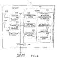
- FIG. 2illustrates an exemplary end node 14 implemented in accordance with the present invention.
- the end node 14may be used by a user as a mobile terminal (MT) or the end node can act as the Mobile Node proxy Server (MNPS) for a mobile terminal (MT).
- MNPSMobile Node proxy Server
- the end node 14includes receiver and transmitter antennas 303 , 305 which are coupled to receiver and transmitter circuitry 302 , 304 respectively, when the end node is connected to the access node 12 via a wireless link.
- the receiver circuitry 302includes a decoder 333 while the transmitter circuitry 304 includes an encoder 335 .
- the receiver transmitter circuits 302 , 304are coupled by a bus 330 to a memory 310 , a processor 306 , and an I/O interface 308 .
- the I/O interface 308is employed.
- Processor 306under control of one or more routines stored in memory 310 , causes the end node 14 to operate in accordance with the methods of the present invention.
- memory 310includes communications routine 323 and end node control routine 325 .
- the end node communications routine 323is used for controlling the end node 14 to perform various communications operations and implement various communications protocols.
- the end node control routine 325is responsible for insuring that the end node operates in accordance with the methods of the present invention and performs the steps described in regard to end node operations and signaling.
- Memory 310also includes a MNPS control routine 326 .
- the MNPS control routine 326is responsible for insuring that the end node operates in accordance with the methods of the present invention and performs the steps described in regard to MNPS operations and signaling.
- the memory 310also includes user/device/application/session/resource information 312 which may be accessed and used to implement the methods of the present invention and/or data structures used to implement the invention.
- User/Device/Application/Session/Resource information 312includes MIP visitor state information 313 described in detail in FIG. 4 .
- Information 312also includes MNPS state 314 that includes addresses of the MNPS when the end node is a MT, or a home address of the MT when the end node 14 is a MNPS, associated security association for securing signaling between the MT and its MNPS, and state indicating whether the MT or the MNPS is presently receiving/sending packets from/to the home address of the end node 14 .
- Information 312also includes application state 315 that describes the intended behavior of the application software on the MT 14 and the MNPS 14 , the application state that is sent from the MT 14 to the MNPS 14 , and the classifier information that is sent to a home agent that describes which packet flows are directed to the MT 14 and which flows are sent to the MNPS 14 for the MT 14 .
- FIG. 3illustrates an exemplary home mobility agent node 15 implemented in accordance with the invention.
- the home mobility agent node 15includes a bus 430 that couples together an I/O interface 408 , a processor (e.g., CPU) 406 and memory 410 .
- the I/O interface 408couples the home mobility agent node 15 to the Internet.
- the memory 410includes routines, which when executed by the processor 406 , cause the home mobility agent node 15 to operate in accordance with the invention.
- Memory 410includes communications routines 423 used for controlling the mobility agent node 15 to perform various communications operations and implement various communications protocols.
- the memory 410also includes a mobility agent control routine 425 used to control the mobility agent node's 15 operation and signaling to implement the steps of the method of the present invention.
- the mobility agent node control routine 425includes a scheduler module 422 used to control transmission scheduling and/or communication resource allocation. Thus, module 422 may serve as a scheduler.
- the memory 410also includes a mobility agent module 426 used to process and send mobility related signaling implementing the steps of the method of the present invention. Thus, module 426 may serve as a Mobile IP Home Agent.
- Memory 410also includes information 412 used by communications routines 423 , control routine 425 and mobility agent module 426 .
- the information 412includes an entry 413 , 413 ′ for each active end node (EN 1 , ENn), respectively.
- information for end node 1 413includes visitor list state 414 , shown in detail in FIG. 4 .
- Information about end node N 413 ′includes visitor list state 414 ′ also shown in detail in FIG. 4
- FIG. 4illustrates example visitor list state 100 , associated with a given mobility agent such as an end node 14 , access node (foreign agent) 12 , or a home mobility agent node (home agent) 15 , implementing list state 313 in FIG. 2 , the visitor list state 214 , 214 ′ in FIG. 1 , and visitor list state 414 , 414 ′ in FIG. 3 , respectively.
- visitor list state 100may include a number of state entries 110 , 120 .
- Visitor state 100includes entries for at least one MN 14 , each entry including state for a MN home address (HoA) 112 , a Home Agent (HA) address 115 , a Care of Address (CoA) 116 , a binding lifetime 113 , MIP signaling flags 117 and MIP security state associations 114 applicable to that mobility agent.
- the visitor list state information 100further includes default CoA state information 110 including the default CoA 118 for an end node 1, e.g., mobile node (MN) or mobile terminal (MT), to be employed by the home agent 15 when the visitor list does not have a valid CoA 116 for the home address 112 .
- Default CoA state information 110also includes MIP Control State 119 used in the operation of MIP signaling and forwarding between the end node 14 and the home agent node 15 .
- the visitor list state information 100includes MNPS CoA State information 120 for a home address 112 to be employed by the home agent node 15 when the visitor list is maintained by the corresponding MNPS of a end node 1, rather than the end node 1, e.g. MT, itself.
- MNPS CoA state 120includes the MNPS CoA 127 that is employed instead of the default CoA 118 or the end node 1 CoA 116 when the MNPS is issuing MIP registrations to the home agent node 15 .
- State 120further includes MIP security state 128 to secure such registrations at the home agent, and MIP control state 129 used for the operation of MIP signaling and forwarding between the MNPS 14 and the home agent 15 .
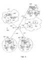
- FIG. 5illustrates an exemplary system 500 comprising a plurality of access nodes 505 , 505 ′, 505 ′′ implemented in accordance with the present invention.
- FIG. 5also depicts communication cells 501 , 501 ′, surrounding each access node 505 , 505 ′, respectively, which represents the coverage area of the radio technology employed by corresponding access node 505 , 505 ′, respectively with end nodes.
- Access node 505 ′′in contrast employs fixed links to end nodes and hence does not employ a communications cell but is otherwise part of the network.
- the same physical and functional elementsare otherwise depicted in each of the communication cells 501 , 501 ′, and the network thus the following description of the elements in the cell 501 surrounding access node 505 is directly applicable to each of the cells 501 , 501 ′, and the network portion containing the access node 505 ′′.
- the depiction of the access node 505is a simplified representation of the access node 12 depicted in FIG. 1 .
- access node 505is shown to include a mobility agent module 507 responsible for the signaling implementing this present invention.
- End nodes 502 , 504are simplified versions of the end node 14 depicted in FIG. 2 .
- Interconnectivity between the access nodes 505 , 505 ′, 505 ′′is provided through network links 510 , 511 , 512 and an intermediate network node 520 .
- Home network 530 in FIG. 5is connected to the rest of the system via link 522 and node 520 .
- Home Network 530further includes network node 536 also connected to link 522 and mobility agent node 532 , connected to node 536 via link 538 and operating as mobility agent of at least end node N 504 .
- Network 540 in FIG. 5is connected to the rest of the system via link 523 and node 520 .
- Network 540further includes network node 546 also connected to link 523 and a correspondence node (CN) 542 , connected to node 546 via link 548 and operating as corresponding node in a data session with at least end node N 504 for illustration of the methods of this present invention.
- Access Node 505is considered to support mobile terminals (MTs) in the communications network 500 providing wireless communications, e.g., via links ( 506 , 508 ) with end nodes (end node (MT) 1 502 , end node (MT) N (X) 504 ).
- MTsmobile terminals
- access node 505 ′is considered to support MTs in the communications network 500 providing wireless communications, e.g., via links ( 506 ′, 508 ′) with end nodes (end node (MT) 1 502 ′, end node (MT) N 504 ′).
- the access node 505 ′′is considered to support fixed links to end nodes that are MNPSs which further support the end nodes that are MTs in the communications system 500 .
- Access node 505 ′′is shown to be coupled via fixed links ( 506 ′′, 508 ′′) to end nodes (end node (MNPS) 1 502 ′′, end node (MNPS) N (Y) 504 ′′), respectively.
- FIGS. 6-8illustrate example embodiments of the various methods of this present invention.
- FIGS. 6-8are simplified versions of the system FIG. 5 including elements as required to further explain this present invention.
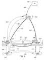
- FIG. 6shows access nodes 505 , 505 ′′, including mobility agent modules 507 , 507 ′′, respectively, providing access to MT end node X 504 , and MNPS end node Y 504 ′′ that provides functionality to the MT end node X 504 .
- FIG. 6also shows home mobility agent node 532 serving end node (MT) X 504 and a CN node 542 being in a communication session with said end node (MT) X 504 .
- MTend node
- solid thin arrowsdepict inner data traffic and the direction of the arrow points to the destination of said data traffic; thick solid lines depict encapsulated inner data traffic and the direction of the arrow points to the destination of said tunnel; dashed lines depict signaling messages used for the registration of an end node to the foreign mobility agent 507 and the home mobility agent 532 , and the direction of the arrow points to the destination of said signaling. Dashed lines are also used for other types of signaling associated with MIP hand-off and with controlling the MNPS functionality.
- FIG. 6shows the packet forwarding and signaling for an exemplary example of the invention in operation in network 500 .
- the dashed arrowsindicate signaling messages and the solid arrows are packet flows.
- the thin solid arrowsare inner packets whilst the thick arrows are encapsulated inner packets using an outer header.
- end node (MT) X 504is initially receiving packets from the CN 542 as packet flow 616 to the home mobility agent node 532 , which tunnels these packets to the access node 505 as packet flow 610 , and then the foreign agent 507 in the access node 505 then decapsulates the packets 610 and forwards them as packets 617 to the end node (MT) X 504 .
- the end node (MT) X 504When the end node (MT) X 504 wishes to invoke the MNPS functionality of the invention, then the end node (MT) X 504 sends registration request signals 601 , 602 towards the home mobility agent 532 , via the foreign agent 507 and receives the registration reply via messages 603 and 604 .
- the registration message 601includes the home address of the end node (MT) X 504 , the address of the mobility agent node 532 , the address of the access node 505 , the end node X CoA field for the home address of the end node (MT) X 504 , and the requested lifetime of the registration.
- the registration messageis intended to cancel the binding between the home address and the CoA of the end node (MT) X 504 in the foreign and home agents 507 , 532 .
- the CoAmay be set equal to the home address and/or the lifetime is set to zero or a very short time value.
- the default CoAis either preconfigured into the home agent via a management process, can be delivered in the MN profile from a policy server, or can be dynamically configured by the end node (MT) X 504 by including a default CoA in this or a previous registration message.
- the default CoAis permanent and is only removed from the home agent mobility node 532 when the default CoA functionality is no longer applicable such as when the home address is no longer allocated to end node (MT) X 504 .
- the home agent 532then tunnels packets that arrive for the home address of end node (MT) X 504 to the default CoA of end node (MNPS) Y 504 ′′ rather than to the dynamic CoA of the end node (MT) X 504 .
- the default CoA in FIG. 6is the address of the agent node 505 ′′ to which the end node (MNPS) Y 504 ′′ is connected.
- End node (MNPS) Y 504 ′′is the MNPS of the end node (MT) X 504 such that packets addressed to the home address of the end node (MT) X 504 are now delivered to end node (MNPS) Y 504 ′′ where the application proxy for that end node (MT) X 504 is located.
- the forwarding at the access node 505 ′′is preconfigured with a binding between the home address of the end node (MT) X 504 and the end node (MNPS) Y 504 ′′ so that the access node 505 ′′ can decapsulate the packets from the home agent 532 and forward them as packets 617 ′′ to the end node (MNPS) Y 504 ′′.
- the end node (MNPS) Y 504 ′′becomes the network end point for packets 617 addressed to the home address of the end node (MT) X 504 whilst the default CoA is active at the home agent 532 .
- the home mobility agent node 532 , foreign mobility agent 507 ′′, end node (MNPS) Y 504 ′′ or any intermediate node that is on the path of the packet flow between the home agent 532 and the end node (MNPS) Y 504 ′′can act as a Network translator and convert the destination address of the packets in the packet flow from the home address of the end node (MT) X 504 to the interface address of the end node (MNPS) Y 504 ′′ so that the end node (MNPS) Y 504 ′′ application proxy can avoid re-using the home address of the end node (MT) X 504 as a network address.
- an end node (MT) X 504to redirect its packets to an end node (MNPS) Y 504 ′′ under the control of the end node (MT) X 504 and its home agent 532 .
- the end node (MNPS) Y 504 ′′receives the packets 617 ′′ and undertakes the processing of the packets and the application data within the packets, as if it was the end node (MT) X 504 .
- the end node (MNPS) Y 504 ′′has an interface that matches the destination address of packets 617 ′′ and passes the application data contained in the packets to the application software in the application proxy that is configured to process said packet data.
- the processing of the packet datais controlled by application proxy configuration state which enables the MNPS at end node Y (MNPS) 504 ′′ to provide services on behalf of the MN in the end node (MT) X 504 to CN 542 .
- These servicesinclude the ability to generate application data, create packets and send said packets to the CN 542 as part of the ongoing communications session, or to any other end node including the end node (MT) X 504 .
- the application proxyis able to send and receive signaling data in signaling packets that can be used to create, maintain and terminate communications sessions with CNs.
- the CN 542may additionally have the default CoA state described in this invention.
- the home agent 532can have a filter associated with the default CoA for a home address of an end node (MT) X 504 that identifies a specific subset of packets addressed to that home address that are to be forwarded to the default CoA when a dynamic CoA is not active.
- the application proxy at the end node (MNPS) Y 504 ′′therefore only needs to be able to provide applications services for said subset of packets rather than for all possible applications employed by the end node (MT) X 504 .
- the filtercan be configured or delivered using any of the methods employed for the default CoA.
- the application proxy configurationcan include filters that limit the type of applications packets can be emitted by the application proxy from the source address of the end node (MT) X 504 , or any associated source address that is translated into the home address of the end node (MT) X 504 .
- a filtercan alternatively be installed into the foreign agent 507 ′′ to police packet flows in either direction between the CN 542 and the end node (MNPS) Y 504 ′′.
- the message 601can include the address of the access node 505 ′′ and an instruction to trigger message 624 and acknowledgment 622 which causes the context state associated with the end node (MT) X 504 at the access node 505 to be transferred to the access node 505 ′′ so that the access node 505 ′′ can police and provide services to the packet flow 617 ′′ and the end node Y (MNPS) 504 ′′, as is provided by the access node 505 to the end node (MT) X 504 and packets 617 .
- MNPSend node Y
- Specific context state examplesare the policy profile, the paging classifier, Multicast group membership and security associations needed by the access nodes 505 , 505 ′′ for the end node (MT) X 504 .
- this context statecan be preconfigured in the access node 505 ′′ via a similar policy process such as AAA signaling that is used to deliver the context state to the access node 505 , and the message 624 only used to carry incremental and/or temporary changes to that preconfigured state.
- Messages 624 and 622can also be used to configure a tunnel 620 between access nodes 505 and 505 ′′ so that in-flight packets towards the end node (MT) X 504 can also be directed to the end node (MNPS) Y 504 ′′.
- the message 618 ′′is sent from the access node 505 ′′ to the end node (MNPS) Y 504 ′′, following message 622 / 624 , to inform end node (MNPS) Y 504 ′′ that it is now responsible for the packets to and from the home address of the end node (MT) X 504 .
- the end node (MT) X 504can issue message 634 to end node (MNPS) Y 504 ′′ using the home address of the end node (MT) X 504 as a source address and the interface address of end node (MNPS) Y 504 ′′ as the destination address.
- Message 634generates a reply message 632 .
- Message 634is used to request that the end node (MNPS) Y 504 ′′ become the end point for packets to and from the home address of the end node (MT) X 504 , to which the end node (MNPS) Y 504 ′′ responds with an acknowledgement message 632 .
- Message 634can include modifications to the application configuration at the application proxy in the end node (MNPS) 504 ′′, such as application control or data state, as well the filter state which is used by the end node (MNPS) Y 504 ′′ to select a subset of packet flows 617 for which the application proxy will process on behalf of the end node (MT) X 504 .
- the reply message 632can include the address of the access node 505 ′′ to which the end node (MNPS) Y 504 ′′ is connected so that the end node (MT) X 504 can include that address in message 601 to the access node 505 so that access node 505 knows the address of the access node 505 ′′ for the context transfer as part of message 624 .
- both the interface address of the end node (MNPS) Y 504 ′′ and its access node 505 ′′can be known in advance at the end node (MT) X 504 .
- Messages 632 and 634need to be at least authenticated and integrity protected to avoid the hijacking of packet flows.
- the end nodes (MT) X 504 and (MNPS) Y 504 ′′therefore share a security association to secure messages between them, tied to the home address of end node (MT) X 504 and the interface address of end node (MNPS) Y 504 ′′. T his security association can be preconfigured, provided by a policy server or dynamically generated.
- the end node (MT) X 504must know its MNPS end node Y 504 ′′ interface address in advance of sending message 634 but the end node (MNPS) Y 504 ′′ can be dynamically informed of the home address for which it is to provide application proxy services via the contents of message 634 .
- end node (MT) X 504When end node (MT) X 504 wishes to reclaim the packet flow from the end node (MNPS) Y 504 ′′, then the end node (MT) X 504 sends and receives messages 601 , 602 , 603 and 604 to install into the home agent 532 and foreign agent 507 the dynamic CoA at its current access node 505 , 505 ′, which therefore overrules the default CoA at the home agent 532 . In advance of this, the end node (MT) X 504 can send message 634 to end node (MNPS) Y 504 ′′ to request back the packet flow and to terminate the application proxy in the end node (MNPS) Y 504 ′′.
- the end node (MNPS) Y 504 ′′can then inform the end node (MT) X 504 in message 632 when it is ready (i.e., when application data is at an appropriate stage to transfer control), and can return any associated application control state or data back to the end node (MT) X 504 so that the end node (MT) X 504 can continue with the application processing.
- Messages 624 and 622can also be triggered by message 601 at the access node 505 to this time install a tunnel 620 ′′ back to the access node 505 , for in-flight packets towards the access node 505 ′′ for the end node (MNPS) Y 504 ′′, creating the reverse of packet flow 620 .
- Messages 624 and 622can also recover the context state from access node 505 ′′ including any changes that have occurred at access node 505 ′′, back to access node 505 .
- Thisenables the access node 505 ′′ to act as a temporary storage point for the context state if the end node (MT) X 504 should leave access node 505 causing that access node to eliminate said context state associated with that end node (MT) X 504 .
- Message 618 ′′is used to inform the end node (MNPS) Y 504 ′′ that it is no longer responsible for the set of packets to and from the home address of the end node (MT) X 504 .
- FIG. 7shows an alternative embodiment of the invention that uses a MNPS CoA in the home agent 532 instead of the default CoA.
- MNPSend node
- Y 504that sends the registration signals to the home agent 532 via the foreign agent 507 ′′ as messages 601 ′′ and 602 ′′ which include the home address of end node (MT) X 504 and the CoA of the end node (MNPS) Y 504 ′′.
- reply messages 603 ′′ and 604 ′′along with the update of the binding in the home agent 532 to redirect packets from tunnel 610 to tunnel 610 ′′.
- the end node (MNPS) Y 504 ′′is then able to redirect packets addressed to the home address away from the end node (MT) X 504 .
- the end node (MNPS) Y 504 ′′ and foreign agent 507 ′′should share a security association with the home agent 532 to secure these messages to avoid redirection attacks from unauthorized nodes.
- the registrations from end node (MNPS) Y 504 ′′do not eliminate the registration state issued by the end node (MT) X 504 itself, both of which are treated independently, but the registration state and specifically the CoA from the end node (MNPS) Y 504 ′′ is prioritized above that of the end node (MT) X 504 . This is so that the end node (MNPS) Y 504 ′′ can safely redirect the packet flows of an end node (MT) X 504 when it is disconnected from the network or suffering a malfunction.
- This time message 601 ′′triggers message 622 which has a reply message 624 .
- Theseare once again used to install temporary packet forwarding 620 between the access node 505 and the access node 505 ′′ and to fetch the context state from the access node 505 .
- messages 601 ′′, 602 ′′, 603 ′′, 604 ′′, 622 and 624are used to redirect packet flow back to the end node (MT) X 504 , and its access node 505 , by canceling the MNPS CoA in the home agent 532 , when the end node (MNPS) Y 504 ′′ no longer wishes to receive packets for the home address of end node (MT) X 504 .
- Message 618is used to inform the end node (MT) X 504 , as a result of messages 622 , 624 whether or not it is presently responsible for packets to its home address.
- the end node (MT) X 504can trigger the end node (MNPS) Y 504 ′′ to send message 601 ′′, to either take or release the redirection of the packets, by first sending message 634 to the end node (MNPS) Y 504 ′′ which again responds with message 632 .
- Other nodessuch as the access node 505 , CN 542 or home agent 532 can alternatively trigger the end node (MNPS) Y 504 ′′ to issue message 601 ′′ using messages similar to message 634 .
- FIG. 8is the same as FIG. 6 apart from the fact that the MNPS CoA of end node (MNPS) Y 504 ′′ is this time a Co-located CoA which is equal to the interface address of end node (MNPS) Y 504 ′′.
- Redirected packet flow 611 ′is therefore now a tunnel directly between the home agent 532 and the end node (MNPS) Y 504 ′′, which avoids the need for the access node 505 ′′ needing a foreign agent function 507 ′′.
- in-flight packets 620can be sent directly to the CCoA of the end node (MNPS) Y 504 ′′ rather than via the access node 505 ′′.
- FIG. 9shows an alternative embodiment of the default CoA functionality in the special case that the end node (MNPS) Y 504 ′′ is on the same mac_layer network as the home agent 532 , which is therefore also the home network 530 ′ of the end node (MT) X 504 .
- the FIG. 9shows the networking between the CN 542 and the network 530 components of FIG. 5 .
- FIG. 9introduces links 508 ′′′ and 506 ′′′ which are used to connect end node (MT) X 504 and end node (MNPS) Y 504 ′′ to the home agent 532 .
- the nodesrun a protocol which distributes the mapping between the mac_layer address of each interface and its associated IP address, such as in the case of Address Resolution Protocol (ARP) or Neighbour Discovery in IPv6 (ND).
- ARPAddress Resolution Protocol
- NDNeighbour Discovery in IPv6
- the home agent 532then tunnels these packets to the current registered dynamic CoA as shown by the large solid arrow.
- the end node X (MT) 504is on the home network 530 ′ then it will issue the ARP message 915 ′′′ onto the mac_layer network, containing its mac_layer address on link 508 ′′′, so that such packets 920 ′′′ are instead forwarded to it.
- This ARP message 915 ′′′cancels the proxy ARP message 902 ′′′ from the home agent 532 to all other nodes on the mac_layer network. Note that the home agent will typically not send message 902 ′′′.
- the end node (MNPS) Y 504 ′′can issue for example, without loss of generality, a proxy ARP message 905 ′′′ to redirect packets to the home address of the end node (MT) X 504 , towards the end node (MNPS) Y 504 ′′ creating packet flow 910 ′′′.
- a proxy ARP message 905 ′′′to redirect packets to the home address of the end node (MT) X 504 , towards the end node (MNPS) Y 504 ′′ creating packet flow 910 ′′′.
- the proxy ARP messages: 902 ′′′ sent by the home agent 532 , 915 ′′′ sent by end node (MT) X 504 , and 905 ′′′ sent by end node (MNPS) Y 504 ′′can be strictly ordered using a priority flag in the ARP messages, or the last message can instead be considered the latest configuration and a system of message suppression using internal priorities used by the nodes to identify who is the present receiver of packets addressed to the home address of end node (MT) X 504 .
- the default CoA capabilitycan be reproduced in this special case by instead storing a default ARP binding in the home agent 532 which is activated when the end node (MT) X 504 is neither on the home network nor has a valid dynamic CoA registered in the home agent 532 .
- the default ARP bindingis then advertised by the home agent and identifies the mac_layer address of the end node (MNPS) Y 504 ′′ rather than the mac layer address of the home agent 532 .
- the access node 505 ′′can contain the home agent 532 whilst still using default and MNPS CoA features.
- MNPSsfor each home address, with filters used to route packets to the correct MNPS functionality for each subset of the packet flows.
- One of said MNPSscan also be located in the same node as the home agent 532 .
- the MNPS softwarecan be located in the access node 505 ′′.
- the inventioncan use Mobile IP v4 and/or v6 signaling and forwarding, including the various forwarding options including route optimisation.
- the various messages detailed in the inventioncan be used in various subsets and combinations as appropriate to the requirements of the application proxy in relation to the subset of packets being redirected from the end node (MT) X 504 .
- the default CoAcan be used to redirect all packets to an allocated home address, that does not have a registered dynamic CoA in the home agent 532 , towards an application proxy that acts as an error-logger by simply capturing the packet headers.
- an extended IP paging systemcan be supported whereby the end node (MT) X 504 can go into sleep at the access node 505 and packets can be redirected to the access node 505 ′′ where a paging classifier is contained in the context state of the end node (MT) X 504 .
- the paging classifiercan decide whether packets are dropped, forwarded to the MNPS or trigger a paging message to the present location of the end node (MT) X 504 , said location being accessible by the access node 505 ′′.
- Packets that are forwarded to the end node (MNPS) Y 504 ′′are processed in the MNPS and application events can then trigger message 601 ′′ to return packet forwarding to the end node (MT) X 504 at its present location which is installed as the CoA in the home agent 532 using message 602 ′′.
- the MNPScan simply send message 632 towards the end node X 504 which will be passed to the access node 505 ′′ and will then trigger the paging function at that access node towards the present location of the end node (MT) X 504 .
- the potential result of the paging functionis the end node (MT) X 504 will wake up and wish to recover its packet reception and forwarding. It will therefore use message 601 to update the home agent with its present CoA, trigger 622 / 624 to recover its context state from the access node 505 ′′ and use message 634 and 622 to recover its application state from the MNPS.
- the MNPSWhilst the end node (MT) X 504 is asleep, the MNPS can issue keep-alive packets for any applications and protocols at the CN that require such keep-alives to maintain a session.
- the message 634 / 632 exchangeis used by the end node (MT) X 504 , along with preconfigured application proxy state, to inform the MNPS of the sessions to be refreshed, the refresh interval, any security state used to secure the keep-alive signalling, the keep-alive peer and the response behaviour if the session terminates or if incoming data packets arrive on that session. This enables the end node X (MT) 504 to go into power efficient extended sleep but not loose connectivity to application servers and networking gateways.
- a content distribution systemcan be developed whereby the end-node (MT) X 504 can order delivery of a piece of content but direct its delivery to the MNPS in the end node (MNPS) Y 504 ′′ using a filter in the home agent 532 .
- the application proxy state in the MNPScan then direct a message to the end node (MT) X 504 when the content has been delivered in its entirety, or simply wait for the end node (MT) X 504 to query its delivery status.
- the end node (MT) X 504 or end node (MNPS) Y 504 ′′can then use the methods of the invention to direct packets back to the end node (MT) X 504 and then the end node (MNPS) Y 504 ′′ can deliver the content to the end node (MT) X 504 .
- Thisenables the end node X (MT) 504 to either go to sleep or use its bandwidth for other purposes whilst the content is delivered to end node (MNPS) Y 504 ′′, and then request delivery when it best suits that end node (MT) X 504 .
- the end node (MNPS) Y 504 ′′can act as a content server for content from the end node (MT) X 504 .
- the end node (MT) X 504can then wake-up and efficiently deliver a content update to end node (MNPS) Y 504 ′′ whilst using filters to direct content requests to the content server at the end node (MNPS) Y 504 ′′.
- the server addressis the same whether or not the end node (MT) X 504 or end node (MNPS) Y 504 ′′ is actually serving the content, so enabling the end node (MT) X 504 to serve a subset of flows, some or all of the time as it so wishes.
- Messages 634 / 632keep the end node applications in synch whilst messages 601 , 602 , 603 , 604 , 622 , 624 and 618 manage the packet forwarding.
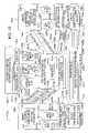
- FIG. 10illustrates an exemplary communications system 1000 in accordance with one particular exemplary embodiment of the present invention.
- the system 1000includes a first node, e.g., mobile node 1001 , a second node, e.g., access node 1003 which may be used as a MIP Foreign Agent, a third node, e.g., a regional mobility agent node 1005 which may be a MIP home agent, a fourth node, e.g., a communication peer node 1007 sometimes called a correspondence node, fifth node, e.g., a network node 1009 , and a sixth node, e.g., an access node 1011 .
- a first nodee.g., mobile node 1001
- a second nodee.g., access node 1003 which may be used as a MIP Foreign Agent
- a third nodee.g., a regional mobility agent node 1005 which may be a MIP
- Mobile node (MN) 1001is coupled to access node 1003 via wireless link 1013 .
- Network node 1009is coupled to access node 1011 via link 1017 .
- Home Agent or Regional Mobility Agent Node 1005is included in a routing system 1019 .
- Home Agent or Regional Mobility Agent Node 1005is coupled to Access Node 1003 , Access Node 1011 , and Communication Peer Node 1007 via links 1023 , 1025 , 1027 respectively.
- Access Nodes 1003 , 1011are normally part of the routing system 1019 .
- Second nodee.g., access node 1003
- has a defined routee.g., a route defined by a routing table included in internal memory, which is used to forward packets with a CoA corresponding to said mobile node 1001 to said mobile node.
- Sixth node, e.g., access node 1011has a defined route, e.g., a route defined by a routing table included in internal memory, which is used to forward packets with a CoA corresponding to said mobile node 1001 to said fifth node 1009 the Mobile Node proxy Server (MNPS), when the MNPS is responsible for processing application packets corresponding to the shared address common to both the MN 1001 and MNPS 1009 .
- MNPSMobile Node proxy Server
- the various nodesmay be located in different addressing domains, with addresses associated with said different domains including different address prefixes used to distinguish between the different addressing domains.
- the system 1000includes at least two addressing domains but may include more, e.g., 3 addressing domains.
- the Home mobility agent node 1005is normally located in a different domain from the FA node, e.g., the second node 1003 , and the FA node 1003 is normally located in the same domain as the regional mobility agent 1005 .
- the other nodes 1011 , 1009may be in the same domain as the FA node 1003 or home agent 1005 , or located in a different domain altogether, e.g., a third addressing domain which is identified by a third prefix which is included in addresses corresponding to nodes located in the third addressing domain.
- MN 1001includes application state 1029 , and application routines 1031 including an IP based communication application 1033 and a second application 1035 , and a shared address 1037 .
- Access node 1003includes a mobility agent 1039 and encapsulation/descapsulation and forwarding routine 1041 .
- Access node 1003may be a base station or access router used by MN 1001 .
- Mobility Agent 1039may act as a Foreign Agent (FA) for MN 1001 while MN 1001 is in the foreign domain in which Access Node 1003 is located.
- Home Agent or Regional Mobility Agent Node 1005includes a bindings table 1043 and an encapsulation/descapsulation forwarding routine 1045 . Life time information may be included with the address binding information included in bindings table 1043 .
- Node 1005may act as the Home Agent (HA) for MN 1001 .
- Communication peer node 1007includes application routines 1047 , e.g., software applications, including an IP based communications application (first application) 1049 and a second application 1051 .
- Fourth node 1007is the correspondence node (CN) to which MN 1001 is corresponding with in an exemplary communications session in which the first application 1033 is involved.
- Network Node 1009operates as an application proxy during at least some period of time when the MN 1001 is unavailable to continue interacting with a first application, and may be a Mobile Node Proxy Server (MNPS).
- MNPSMobile Node Proxy Server
- the MNPS 1009receives packets corresponding to an application flow which have a destination address corresponding to the MN 1001 and processes the received packets. Processing may include generating at least one packet from the body of two received packets and transmitting the generated packet to the CN 1007 .
- Node unavailabliltymay be the result of a decision by the MN 1001 , e.g., to enter a sleep state or due to an event outside the control of the MN 1003 such as signal loss due to interference.
- node 1009may communicate with CN 1007 in place of MN 1001 .
- Routing control signals sent to the routing system 1019are used to insure that a flow of packets corresponding to an application is routed to the MN or MNPS responsible for processing the packets corresponding to the particular application at any given point in time.
- different packet flows, corresponding to different MN applications 1033 , 1035can be classified by the routing system 1019 and routed to different nodes.
- different MNPS nodes 1009may be used to support different applications on behalf of the MN 1001 when the MN is unavailable.
- the MNmay be unavailable for one application it can continue to processes packets relating to another application.
- responsibility for one or more subsets of the applications 1033 , 1035 which the MN is actively usingmay be handed off to the MNPS 1009 at different points in time.
- the correspondence node 1007need not be informed as to whether the MN 1001 or MNPS 1009 is receiving and processing packets corresponding to a particular application and may continue operation under the assumption that it is interacting with the MN 1001 in regard to a particular application at all times.
- signals to the routing system 1019 regarding redirection of packets corresponding to a particular application associated with the MN 1001may be sent to the RS 1019 from either the MN 1001 or MNPS 1009 .
- These signalsnormally include a routing identifier which identifies the node 1001 or 1009 to which the application packets are to be directed.
- the routing identifieridentifies an intermediate node, e.g., FA 1003 which has a determined route to the node to which the application packets are to be directed.
- the identified intermediate node receiving the packets intended for the MN or MNPSforwards the packets to the destination node, e.g., the MN or MNPS with which it has the routing relationship. This relationship will normally be reflected in binding tables used to route packets to the MN or MNPS which is included in the intermediate node 1003 or 10011 .
- the routing identifier sent to the RS 1019may be, e.g., an address corresponding the MN or MNPS or a combination of an address and some other routing information such as a weight used to affect a routing decision made by the RS 1019 .
- the routing identifiermay further optionally include additional information, such as a packet classifier, to enable the routing system to detect packets belonging to the first or second applications 1049 , 1051 at the CN 1007 , and to direct the first and second application packets to different Nodes 1001 , 1009 . When the packet classifier is missing from the routing identifier, then the routing system redirects all packets in the first packet flow 1069 to the identified node in the routing identifier.
- Node 1009includes application state 1053 , application proxy routines 1055 including an IP based communication application proxy routine corresponding to the first application 1057 and a second application proxy routine 1059 corresponding to the second supported application, and shared address 1037 .
- Shared Address 1037corresponds to both MN 1001 and network node (MNPS) 1009 .
- Access Node 1011includes a Mobility Agent 1061 and an Encapsulation/Decapsulation forwarding routine 1063 . Access Node 1011 couples network node 1009 to the rest of the system 1000 .
- MN 1001 or Network Node (MNPS) 1009sends a first message 1065 to the Routing System 1019 and its node 1005 .
- FIG. 10shows Message 1065 being sent by network node (MNPS) 1009 .
- First Message 1065includes a routing identifier 1067 .
- Routing identifier 1067uniquely identifies a node being in the group of nodes including MN 1001 , network node (MNPS) 1009 , and a node having a defined route to MN 1001 or MNPS 1009 such as the second node 1003 and 6 th node 1011 .
- the routing system 1019directs a first packet flow 1069 from CN 1007 , e.g., a flow corresponding to the first application to either MN 1001 or network node (MNPS) 1009 . At least some of the packets in packet flow 1069 correspond to first application packets 1071 .
- the node identified by the routing identifiere.g., one of MN 1001 or network node (MNPS) 1009 , receives the first packet flow 1069 at any given point in time.
- the packet flowis directed to the node 1001 or 1009 which is responsible for application processing and interacting with the CN 1007 at any given point in time.
- First packet flow 1069may include, e.g., during a first period of time, first packet flow 1069 a from CN 1007 to Home Agent Mobility Node 1005 , first packet flow 1069 b from Home Agent Mobility Node 1005 to Access Node 1003 , and first packet flow 1069 c from Access Node 1003 to MN 1001 .
- first packet flow 1069includes: first packet flow 1069 a from CN 1007 to Home Agent Mobility Node 1005 , alternate first packet flow 1069 d from Home Agent Mobility Node 1005 to Access Node 1011 , and alternate first packet flow 1069 e from Access Node 1011 to Network Node (MNPS) 1009 .
- MNPSNetwork Node
- IP based communications application routine 1033processes the received packets and generates additional packets containing application data 1071 as a result of said application processing, and transmits the packets in additional packet flow 1073 to CN 1007 .
- Additional packet flow 1073includes: additional packet flow 1073 a from MN 1001 to Access Node 1003 , additional packet flow 1073 b from Access Node 1003 to Home Agent Mobility Node 1005 , and additional packet flow 1073 c from Home Agent Mobility Node 1005 to CN 1007 .
- IP based communication application proxy routine 1057processes the received packets and generates additional packets as a result of said proxy application processing, and transmits the packets in additional packet flow 1073 including: alternate additional packet flow 1073 d from Network Node (MNPS) 1009 to Access Node 1011 , alternate additional packet flow 1073 e from Access Node 1011 to Home Agent Mobility Node 1005 , additional packet flow 1073 c from Home Agent Mobility Node 1005 to CN 1007 .
- a transfer message 1075is sent from MN 1001 to network node (MNPS) 1009 .
- This message 1075is used to initiate a transfer of responsibility for processing application packets originating from the CN 1007 from the first node 1001 or fifth node 1009 to the one of the first and fifth nodes which is not responsible at the time of the transfer message 1075 for application processing.
- Transfer message 1075may include the routing identifier which identifies the node which is to take over responsibility for application processing.
- Network node (MNPS) 1009responds to transfer message by transmitting first message 1065 which includes said routing identifier.
- Additional Message 1077 from MN 1001 to network node (MNPS) 1009defines the requirements of the MN 1001 for the processing of packets by the application proxy, network node (MNPS) 1009 and is transmitted when said MNPS 1009 is to take over responsibility for application processing from said mobile node 1001 .
- State Informationfor example MN application state 1029 is also included in Message 1077 and may be transferred into MNPS application state 1053 . This allows the MNPS to continue application processing from the point at which the MN 1001 transferred responsibility for application processing to the MNPS 1009 .
- a Processing Results/State Message 1079 from network node (MNPS) 1009 to MN 1001returns information to MN 1001 derived from the processing of packets by the application proxy, network node (MNPS) 1009 .
- the returned informationmay include a packet, e.g., an application data packet, generated from processing the body of at least two packets corresponding to the first packet flow which are received by the MNPS 1009 .
- This messageis sent when responsibility for application processing is being returned to the mobile node 1001 thereby allowing the mobile node to continue application processing from the point where the MNPS 1009 ceased being responsible for application processing.
- a second applicationis supported by CN 1007 through a second application routine 1051 .
- the second applicationis supported by MN 1001 through the use of a second application routine 1035 , and in Network Node (MNPS) 1009 through the use of second application proxy routine 1059 .
- a second application packet flow 1081 including second application packets 1083is shown in FIG. 10 including: second application packet flow 1081 a from CN 1007 to Home Agent Mobility Node 1005 , second application packet flow 1081 b from Home Agent Mobility Node 1005 to Access Node 1003 , and second application packet flow 1081 c from Access Node 1003 to MN 1001 .
- the packet flowcould have been directed to Network Node (MNPS) 1009 instead of MN 1001 at a different time.
- the routing systemcan act as a filter sending application packets corresponding to one MN application to the MN proxy 1009 while still sending application packets corresponding to the second MN application to the mobile node 1001 . It should be appreciated that mobile node availability may be different for different applications supported by the MN at the same time.
- the first messageindicates whether packets corresponding to a particular individual application or applications identified in the message are to be redirected to the identified node or if packets corresponding to all applications supported by the MN 1001 are to be redirected, e.g., to the MNPS 1009 .
- packets corresponding to different applicationsmay correspond to different packet flows for routing system purposes despite being having a source address corresponding to the CN address and a destination address corresponding to the shared address of the first and fifth nodes 1001 , 1009 .
- the third node 1005 , fifth node 1009 and sixth nodes 1011are on the same network and therefore share mac-layer connectivity.
- the third node and the sixth nodesmay be the same node which includes both a home and foreign mobility agent.
- the fifth nodecan issue a first message 1065 containing a routing identifier 1067 which is the mac-layer address of the fifth node. This is entered into the binding table 1043 in the third node as the current mac-layer CoA for the first packet flow such that packets are forwarded to the fifth node via the mac-layer address of the fifth node.
- this mac-layer CoAcan also be stored in the binding table 1043 as a default mac-layer CoA such that when the lifetime of binding table entry pointing to the second address (CoA) of the first node at the second node expires, then packets are automatically diverted in the third node to the fifth node via mac-layer forwarding.
- the first nodecan issue a first message 1065 with a routing identifier 1067 equal to its mac_address which due to the broadcast nature of such natures is received by the third, fifth and sixth nodes, which causes the fifth node to stop refreshing its mac_address in the binding table for the first packet flow.
- This new mac-layer CoAsupercedes that previously issued by the fifth node and therefore the first packet flow will be directed to the first node.
- addressed assigned to various nodesmay be located in the same or different addressing domains.
- the addresses assigned to the first, third and fifth nodesare in a first addressing domain.
- the home address of the MN 1001is from the same address prefix as the address of the third node and is shared with the fifth node.
- a fifth address associated with either the fifth or sixth nodesis often in a second addressing domain (e.g., the CoA address of the MNPS 1009 is normally from the same address prefix as the address of the access router).
- the second node and a second address corresponding to the second nodecan be in yet another addressing domain, e.g., in a third addressing domain.
- the first, second and third addressing domainsinclude correspond to at least two different addressing domains. In other cases, the first, second and third addresses are in three different addressing domains. In still yet other embodiments, the first, the second and the third addresses are all in the same addressing domain.
- Addressing domainsare different if the addresses used within the domains have different address prefixes of the same prefix length, i.e. the set of N most significant address bits are different.
- addresses having the same prefix of length Nare determined to be in the same domain where N indicate prefix length and thus the number of bits used to distinguish between different domains.
- at least one of the first, second and third addressing domainsis different from another one of said first, second and third addressing domains with addresses corresponding to different domains including different address prefixes.
- said first and third addressing domainsare the same and said second addressing domain is different from said first and second addressing domains.
- the second and third addressing domainsare the same, and said first addressing domain is different from said first and second addressing domains.
- One or more addressesmay be associated with each node, the associated address having the address prefix of the addressing domain in which the node is located.
- nodes described hereinare implemented using one or more modules to perform the steps corresponding to one or more methods of the present invention, for example, signal processing, message generation and/or transmission steps.
- modulesmay be implemented using software, hardware or a combination of software and hardware.
- Many of the above described methods or method stepscan be implemented using machine executable instructions, such as software, included in a machine readable medium such as a memory device, e.g., RAM, floppy disk, etc. to control a machine, e.g., general purpose computer with or without additional hardware, to implement all or portions of the above described methods, e.g., in one or more nodes.
- the present inventionis directed to a machine-readable medium including machine executable instructions for causing a machine, e.g., processor and associated hardware, to perform one or more of the steps of the above-described method(s).
- a machinee.g., processor and associated hardware
- the methods and apparatus of the present inventionare applicable to a wide range of communications systems including many OFDM, CDMA and other non-OFDM systems.
- the methods and apparatus of the present inventionmay be, and in various embodiments are, used with CDMA, orthogonal frequency division multiplexing (OFDM), and/or various other types of communications techniques which may be used to provide wireless or fixed communications links between access nodes and mobile nodes.
- the access nodesare implemented as base stations which establish communications links with mobile nodes using OFDM and/or CDMA.
- the mobile nodesare implemented as notebook computers, personal data assistants (PDAs), or other portable devices including receiver/transmitter circuits and logic and/or routines, for implementing the methods of the present invention.
Landscapes
- Engineering & Computer Science (AREA)
- Computer Networks & Wireless Communication (AREA)
- Signal Processing (AREA)
- Computer Security & Cryptography (AREA)
- Computer Hardware Design (AREA)
- Computing Systems (AREA)
- General Engineering & Computer Science (AREA)
- Databases & Information Systems (AREA)
- Mobile Radio Communication Systems (AREA)
- Data Exchanges In Wide-Area Networks (AREA)
Abstract
Description
- 1) Both the MN and the proxy MN server could, and in some embodiments does, issue gratuitous ARPs but with different priorities such that the MN will win if present on the subnet, causing the proxy server to cease proxy ARP whilst it sees ARPs from the MN.
- 2) Before the MN binding is lost in the HA, the MN could, and in some embodiments does, issue a signal to the proxy MN server explicitly requesting it to act on the MNs behalf wrt ARPs.
- 3) A HA could, and in some embodiments does, have a default CoA installed for the MN such that whilst the MN has no active binding, packets are instead forwarded to the default CoA which points to the location of the proxy MN server. This has the additional benefit of explicitly removing the ARP context between the MN and the proxy MN server, and enables the proxy MN server to be located off the home subnet, on any foreign subnet, and specifically behind a firewall in the operator web-farm and/or operations centre.
- 4) The MIP could, and in some embodiments does, also use a MIP hand-off to specifically inform the HA to install a long lifetime binding that points to the default CoA which is either a CCoA of the proxy MN server, or a FA CoA of a router in front of the proxy MN server, whilst the MN is away. The MIP signalling looks like a forward (proactive) hand-off towards the proxy MN server CoA and has the advantage of giving the MN specific feedback from the HA (MIP Reply) and the proxy MN server (via BU/Buack) about the progress of the hand-off. Alternatively, the MN can request that the MNPS issues a reactive hand-off to transfer forwarding towards the MNPS CoA in the HA, a binding which is maintained by the MNPS. In addition, the MN can transfer layer2 and IP layer state to the proxy MN server using Context transfer mechanisms to assist that server in processing the incoming traffic, and to act as a storage point for MN state. Application state can also be sent between the MN and the MNPS.
- 1) Fault management. Packets arriving at a HA with no current CoA binding from the MN indicates a potential error in the system. Rather than simply dropping and losing the packet, forwarding them to the proxy MN server enables a record of the packet headers to be taken so that they can be correlated with other records to identify what went wrong in the system.
- 2) Paging. Whilst the MN is sleeping, incoming packets are forwarded to the proxy MN server where a paging classifier is interrogated and a decision is made as to whether or not to page the MN given the packet details, e.g., data contents. The paging system can then be used to locate the MN. Once located and contacted by the paging system the proxy MN server hands-off to the MN which appears to the system in terms of MIP signalling as if the MN actually moved from the proxy to the present FA. During this hand-off, the BU from the MN can be used to cause forwarding of packets at the proxy MN server through to the MN, and Context transfer can be used to transfer locally stored MN state, e.g., current application and MN related communication information, from the proxy MN server back to the FA and the MN so that the MNs state accurately reflects the status at the point the proxy MN server transferred application responsibility back to the MN.
- 3) Application proxies. The proxy MN server can be statically configured, or dynamically programmed by the MN, with information about application processing that the proxy can undertake for the MN whilst it is away. This is useful for a number of reasons. Firstly, a number of Internet applications issue keep-alives and need responses from the MN to remain active. The MN would therefore have the choice of either being prevented from moving into power efficient sleep state for longer than the keep-alive timers, or it would have to lose application liveness. The proxy MN server eliminates this problem because it can instead act on the MNs behalf in a controlled manner, to respond to selected keep-alives whilst the MN is sleeping (for IPSEC, VPN apps, mail servers, the MIP default CoA registration, SIP servers, streaming servers, multicast group memberships etc). Secondly, the MN can order processes to complete e.g., via interaction with the proxy MN server, whilst it is sleeping/missing. Such processes include content distribution (web-pages, files, video streams, software etc), mail uploads and downloads and in fact any application flow that could be more quickly routed through the proxy than directed to or from the MN, or that enables the MN to sleep and hence download content using bursty airlink opportunities. The proxy MN server could then optionally page the MN to inform it that the process has completed. The MN can then wake-up and rapidly download the content from the proxy or receive the delivery notification confirmation. For such application control, the proxy MN server may utilize an application proxy for each such application (web caches and content distribution mechanisms already exist) and signalling systems to control what processes those proxies keep-alive and/or complete in its absence, and the action to undertake when the process terminates (or keep-alive fails). Exemplary actions include paging the MN, store and forward, store until the MN wakes up and triggers the queries the application proxy cache. A range of other triggers and applications activities can be imagined within this general framework.
Claims (25)
Priority Applications (2)
| Application Number | Priority Date | Filing Date | Title |
|---|---|---|---|
| US10/425,151US7623497B2 (en) | 2002-04-15 | 2003-04-29 | Methods and apparatus for extending mobile IP |
| US12/504,501US9226139B2 (en) | 2002-04-15 | 2009-07-16 | Methods and apparatus for extending mobile IP |
Applications Claiming Priority (5)
| Application Number | Priority Date | Filing Date | Title |
|---|---|---|---|
| US37265502P | 2002-04-15 | 2002-04-15 | |
| US42633202P | 2002-11-14 | 2002-11-14 | |
| US10/413,888US7366147B2 (en) | 2002-04-15 | 2003-04-14 | Methods and apparatus for tunneling between different addressing domains |
| US46551003P | 2003-04-25 | 2003-04-25 | |
| US10/425,151US7623497B2 (en) | 2002-04-15 | 2003-04-29 | Methods and apparatus for extending mobile IP |
Related Parent Applications (1)
| Application Number | Title | Priority Date | Filing Date |
|---|---|---|---|
| US10/413,888Continuation-In-PartUS7366147B2 (en) | 2002-04-15 | 2003-04-14 | Methods and apparatus for tunneling between different addressing domains |
Related Child Applications (1)
| Application Number | Title | Priority Date | Filing Date |
|---|---|---|---|
| US12/504,501ContinuationUS9226139B2 (en) | 2002-04-15 | 2009-07-16 | Methods and apparatus for extending mobile IP |
Publications (2)
| Publication Number | Publication Date |
|---|---|
| US20040013099A1 US20040013099A1 (en) | 2004-01-22 |
| US7623497B2true US7623497B2 (en) | 2009-11-24 |
Family
ID=46299216
Family Applications (2)
| Application Number | Title | Priority Date | Filing Date |
|---|---|---|---|
| US10/425,151Active2026-11-01US7623497B2 (en) | 2002-04-15 | 2003-04-29 | Methods and apparatus for extending mobile IP |
| US12/504,501Active2025-11-05US9226139B2 (en) | 2002-04-15 | 2009-07-16 | Methods and apparatus for extending mobile IP |
Family Applications After (1)
| Application Number | Title | Priority Date | Filing Date |
|---|---|---|---|
| US12/504,501Active2025-11-05US9226139B2 (en) | 2002-04-15 | 2009-07-16 | Methods and apparatus for extending mobile IP |
Country Status (1)
| Country | Link |
|---|---|
| US (2) | US7623497B2 (en) |
Cited By (6)
| Publication number | Priority date | Publication date | Assignee | Title |
|---|---|---|---|---|
| US20080310349A1 (en)* | 2007-06-18 | 2008-12-18 | Qualcomm Incorporated | Multiple bindings having independent forward and reverse link bindings for mobile internet protocols |
| US8667513B1 (en) | 2011-03-29 | 2014-03-04 | Sprint Communications Company L.P. | Dormancy timer adjustment in a wireless access node based on wireless device application status |
| US20150133140A1 (en)* | 2004-07-20 | 2015-05-14 | Google Technology Holdings LLC | System and method for silent retry |
| US9143386B1 (en) | 2010-09-27 | 2015-09-22 | Sprint Communications Company L.P. | Remote keep-alive message management in a wireless communication network |
| US9226139B2 (en) | 2002-04-15 | 2015-12-29 | Qualcomm Incorporated | Methods and apparatus for extending mobile IP |
| US10212654B2 (en) | 2013-07-12 | 2019-02-19 | Convida Wireless, Llc | Neighbor discovery to support sleepy nodes |
Families Citing this family (82)
| Publication number | Priority date | Publication date | Assignee | Title |
|---|---|---|---|---|
| US6959341B1 (en) | 2000-12-20 | 2005-10-25 | Cisco Technology, Inc. | Dynamic network allocation for mobile router |
| US7295551B1 (en)* | 2000-12-28 | 2007-11-13 | Cisco Technology, Inc. | Support mobile device in asymmetric link environment |
| US7308263B2 (en)* | 2001-02-26 | 2007-12-11 | Kineto Wireless, Inc. | Apparatus for supporting the handover of a telecommunication session between a licensed wireless system and an unlicensed wireless system |
| US20030119490A1 (en) | 2001-02-26 | 2003-06-26 | Jahangir Mohammed | Wireless communications handset for facilitating licensed and unlicensed wireless communications, and method of operation |
| JP4000906B2 (en) | 2002-05-22 | 2007-10-31 | 日本電気株式会社 | Packet transfer route optimization method, packet transfer apparatus, and program |
| US7787572B2 (en) | 2005-04-07 | 2010-08-31 | Rambus Inc. | Advanced signal processors for interference cancellation in baseband receivers |
| US7634269B2 (en)* | 2002-10-18 | 2009-12-15 | Kineto Wireless, Inc. | Apparatus and method for extending the coverage area of a licensed wireless communication system using an unlicensed wireless communication system |
| US7873015B2 (en) | 2002-10-18 | 2011-01-18 | Kineto Wireless, Inc. | Method and system for registering an unlicensed mobile access subscriber with a network controller |
| US7606190B2 (en) | 2002-10-18 | 2009-10-20 | Kineto Wireless, Inc. | Apparatus and messages for interworking between unlicensed access network and GPRS network for data services |
| US7565145B2 (en)* | 2002-10-18 | 2009-07-21 | Kineto Wireless, Inc. | Handover messaging in an unlicensed mobile access telecommunications system |
| KR20070044072A (en) | 2002-10-18 | 2007-04-26 | 키네토 와이어리즈 인코포레이션 | Apparatus and method for extending coverage area of licensed wireless communication system using unlicensed wireless communication system |
| US7369859B2 (en)* | 2003-10-17 | 2008-05-06 | Kineto Wireless, Inc. | Method and system for determining the location of an unlicensed mobile access subscriber |
| US7953423B2 (en)* | 2002-10-18 | 2011-05-31 | Kineto Wireless, Inc. | Messaging in an unlicensed mobile access telecommunications system |
| US7471655B2 (en)* | 2003-10-17 | 2008-12-30 | Kineto Wireless, Inc. | Channel activation messaging in an unlicensed mobile access telecommunications system |
| US7349698B2 (en)* | 2002-10-18 | 2008-03-25 | Kineto Wireless, Inc. | Registration messaging in an unlicensed mobile access telecommunications system |
| US7885644B2 (en) | 2002-10-18 | 2011-02-08 | Kineto Wireless, Inc. | Method and system of providing landline equivalent location information over an integrated communication system |
| US7640008B2 (en)* | 2002-10-18 | 2009-12-29 | Kineto Wireless, Inc. | Apparatus and method for extending the coverage area of a licensed wireless communication system using an unlicensed wireless communication system |
| US7668541B2 (en)* | 2003-01-31 | 2010-02-23 | Qualcomm Incorporated | Enhanced techniques for using core based nodes for state transfer |
| US7283822B2 (en)* | 2003-10-17 | 2007-10-16 | Kineto Wireless, Inc. | Service access control interface for an unlicensed wireless communication system |
| US7272397B2 (en) | 2003-10-17 | 2007-09-18 | Kineto Wireless, Inc. | Service access control interface for an unlicensed wireless communication system |
| US20080132207A1 (en)* | 2003-10-17 | 2008-06-05 | Gallagher Michael D | Service access control interface for an unlicensed wireless communication system |
| JP2005160054A (en)* | 2003-11-04 | 2005-06-16 | Matsushita Electric Ind Co Ltd | Mobile communication method and mobile communication device |
| US7873036B2 (en)* | 2004-02-03 | 2011-01-18 | Nokia Siemens Networks Oy | Method and apparatus to provide group management of multiple link identifiers for collective mobility |
| US7725600B2 (en)* | 2004-02-03 | 2010-05-25 | Nokia Corporation | Method and apparatus providing address management in a flat structure mobile network |
| US7957348B1 (en) | 2004-04-21 | 2011-06-07 | Kineto Wireless, Inc. | Method and system for signaling traffic and media types within a communications network switching system |
| US8041385B2 (en) | 2004-05-14 | 2011-10-18 | Kineto Wireless, Inc. | Power management mechanism for unlicensed wireless communication systems |
| US7962623B2 (en)* | 2004-06-30 | 2011-06-14 | Microsoft Corporation | Sustaining session connections |
| US7940746B2 (en) | 2004-08-24 | 2011-05-10 | Comcast Cable Holdings, Llc | Method and system for locating a voice over internet protocol (VoIP) device connected to a network |
| JP2006080930A (en)* | 2004-09-10 | 2006-03-23 | Hitachi Communication Technologies Ltd | Communication system, server, router, and mobile terminal |
| US20060239277A1 (en)* | 2004-11-10 | 2006-10-26 | Michael Gallagher | Transmitting messages across telephony protocols |
| WO2006086756A2 (en)* | 2005-02-09 | 2006-08-17 | Kineto Wireless Inc. | Unlicensed mobile access network (uman) system and method |
| US7933598B1 (en) | 2005-03-14 | 2011-04-26 | Kineto Wireless, Inc. | Methods and apparatuses for effecting handover in integrated wireless systems |
| US7756546B1 (en) | 2005-03-30 | 2010-07-13 | Kineto Wireless, Inc. | Methods and apparatuses to indicate fixed terminal capabilities |
| JP4427483B2 (en)* | 2005-04-27 | 2010-03-10 | 株式会社東芝 | Communication apparatus and communication method |
| GB2440704B (en)* | 2005-06-21 | 2009-10-14 | Motorola Inc | Method and apparatus to facilitate mobile station communications using internet protocol based communications |
| GB2440703B (en)* | 2005-06-21 | 2009-11-11 | Motorola Inc | System and method for paging and location update in a network |
| DE112006001655B4 (en)* | 2005-06-21 | 2011-03-03 | Motorola, Inc., Schaumburg | A method and apparatus for facilitating communication using replacement and care of internet protocol addresses |
| US7778229B2 (en)* | 2005-07-29 | 2010-08-17 | Cisco Technology, Inc. | Optimized IP address use in a mobile IP environment |
| US7843900B2 (en) | 2005-08-10 | 2010-11-30 | Kineto Wireless, Inc. | Mechanisms to extend UMA or GAN to inter-work with UMTS core network |
| US7515575B1 (en) | 2005-08-26 | 2009-04-07 | Kineto Wireless, Inc. | Intelligent access point scanning with self-learning capability |
| US8825907B2 (en)* | 2005-09-15 | 2014-09-02 | Gendband US LLC | Incorporating a mobile device into a peer-to-peer network |
| US20070112938A1 (en)* | 2005-11-17 | 2007-05-17 | Nokia Corporation | Intermediary, source and methods for sharing content |
| US7882255B2 (en)* | 2006-03-29 | 2011-02-01 | Intel Corporation | Method and apparatus for maintaining local area network (“LAN”) and wireless LAN (“WLAN”) security associations |
| US8165086B2 (en) | 2006-04-18 | 2012-04-24 | Kineto Wireless, Inc. | Method of providing improved integrated communication system data service |
| US20070254677A1 (en)* | 2006-05-01 | 2007-11-01 | Motorola, Inc. | Method and system to enable paging for mobile ip nodes |
| US20080039086A1 (en)* | 2006-07-14 | 2008-02-14 | Gallagher Michael D | Generic Access to the Iu Interface |
| US20080076425A1 (en)* | 2006-09-22 | 2008-03-27 | Amit Khetawat | Method and apparatus for resource management |
| US7912004B2 (en)* | 2006-07-14 | 2011-03-22 | Kineto Wireless, Inc. | Generic access to the Iu interface |
| US7852817B2 (en)* | 2006-07-14 | 2010-12-14 | Kineto Wireless, Inc. | Generic access to the Iu interface |
| JP4764279B2 (en)* | 2006-07-28 | 2011-08-31 | 富士通株式会社 | Relay device |
| US8036664B2 (en)* | 2006-09-22 | 2011-10-11 | Kineto Wireless, Inc. | Method and apparatus for determining rove-out |
| US20080076392A1 (en)* | 2006-09-22 | 2008-03-27 | Amit Khetawat | Method and apparatus for securing a wireless air interface |
| US8204502B2 (en) | 2006-09-22 | 2012-06-19 | Kineto Wireless, Inc. | Method and apparatus for user equipment registration |
| US7995994B2 (en)* | 2006-09-22 | 2011-08-09 | Kineto Wireless, Inc. | Method and apparatus for preventing theft of service in a communication system |
| US8073428B2 (en) | 2006-09-22 | 2011-12-06 | Kineto Wireless, Inc. | Method and apparatus for securing communication between an access point and a network controller |
| US8019331B2 (en)* | 2007-02-26 | 2011-09-13 | Kineto Wireless, Inc. | Femtocell integration into the macro network |
| KR100992968B1 (en)* | 2007-04-06 | 2010-11-08 | 삼성전자주식회사 | Network switch and address conflict prevention method |
| US8102815B2 (en)* | 2007-07-12 | 2012-01-24 | Telefonaktiebolaget L M Ericsson (Publ) | Proxy mobility optimization |
| US8634344B2 (en) | 2007-08-06 | 2014-01-21 | Marvell World Trade Ltd. | Dynamic internet protocol addressing solutions with network-based mobility |
| WO2009039318A1 (en)* | 2007-09-18 | 2009-03-26 | Kineto Wireless, Inc. | Method and system for supporting large number of data paths in an integrated communication system |
| JPWO2009044539A1 (en)* | 2007-10-05 | 2011-02-03 | パナソニック株式会社 | Communication control method, network node, and mobile terminal |
| US8060086B1 (en)* | 2007-11-02 | 2011-11-15 | Sprint Spectrum L.P. | Method and apparatus for processing mobile-IP registration requests |
| KR20090051372A (en)* | 2007-11-19 | 2009-05-22 | 한국전자통신연구원 | Apparatus and method for allowing transmission delay in mobile IP network |
| US8850070B2 (en)* | 2008-03-07 | 2014-09-30 | Citrix Systems, Inc. | Systems and methods for content injection |
| US20090262702A1 (en)* | 2008-04-18 | 2009-10-22 | Amit Khetawat | Method and Apparatus for Direct Transfer of RANAP Messages in a Home Node B System |
| US20100041387A1 (en)* | 2008-08-15 | 2010-02-18 | Amit Khetawat | Method and Apparatus for Inter Home Node B Cell Update Handling |
| US9210125B1 (en) | 2008-10-17 | 2015-12-08 | Honeywell International Inc. | System, method and apparatus for binding communication devices through common association |
| US8111691B2 (en) | 2008-10-31 | 2012-02-07 | Cisco Technology, Inc. | Graceful network merge by performing a graceful transition of conflicting routing identifiers |
| JP5151924B2 (en)* | 2008-11-19 | 2013-02-27 | 富士通株式会社 | Power management proxy device, server device, server power management method using proxy device, proxy device power management program, server device power management program |
| US9065685B2 (en)* | 2009-02-13 | 2015-06-23 | Cisco Technology, Inc. | Network switch employing a proxy to facilitate power savings in a telephone network |
| US20100268981A1 (en)* | 2009-04-20 | 2010-10-21 | Futurewei Technologies, Inc. | System and Method for Tunneling System Error Handling Between Communications Systems |
| EP2498528A1 (en)* | 2009-11-06 | 2012-09-12 | Fujitsu Limited | Radio base station, communication system and communication control method |
| US20120084388A1 (en)* | 2010-04-02 | 2012-04-05 | Xavier De Foy | Inter ue transfer between mobile internet protocol clients |
| US20130114597A1 (en)* | 2010-07-20 | 2013-05-09 | Sharp Kabushiki Kaisha | Proxy server, relay method, communication system, relay control program, and recording medium |
| US8532074B2 (en) | 2010-07-29 | 2013-09-10 | Microsoft Corporation | Energy-efficient on-the-fly Wi-Fi hotspot using mobile devices |
| WO2012144134A1 (en)* | 2011-04-21 | 2012-10-26 | 村田機械株式会社 | Relay server and relay communication system |
| KR101796532B1 (en)* | 2011-06-22 | 2017-11-10 | 삼성전자주식회사 | System for saving energy through controlling of sleep mode and method for operating system |
| TWI577154B (en)* | 2014-10-31 | 2017-04-01 | 宏碁股份有限公司 | Method for keeping remote connection, electronic device and sever |
| US10015744B2 (en)* | 2015-01-05 | 2018-07-03 | Qualcomm Incorporated | Low power operations in a wireless tunneling transceiver |
| US10728748B2 (en) | 2016-03-24 | 2020-07-28 | Motorola Mobility Llc | Method and device for establishing a peer-to-peer connection in a mobile communication network |
| US10172044B2 (en)* | 2016-03-24 | 2019-01-01 | Motorola Mobility Llc | Method and device for data communication over a peer-to-peer connection in a mobile communication network |
| US10237079B2 (en) | 2017-04-05 | 2019-03-19 | Cisco Technology, Inc. | Intelligent network sleep proxy for low power sleeping devices |
Citations (39)
| Publication number | Priority date | Publication date | Assignee | Title |
|---|---|---|---|---|
| US5572528A (en) | 1995-03-20 | 1996-11-05 | Novell, Inc. | Mobile networking method and apparatus |
| US5806007A (en) | 1995-10-18 | 1998-09-08 | Telefonaktiebolaget Lm Ericsson | Activity control for a mobile station in a wireless communication system |
| US5898922A (en) | 1994-05-20 | 1999-04-27 | Siemens Aktiengesellschaft | Mobile radio system |
| US5903559A (en) | 1996-12-20 | 1999-05-11 | Nec Usa, Inc. | Method for internet protocol switching over fast ATM cell transport |
| US5987323A (en) | 1994-07-20 | 1999-11-16 | Nokia Telecommunications Oy | Starting a short message transmission in a cellular communication system |
| US6256300B1 (en) | 1998-11-13 | 2001-07-03 | Lucent Technologies Inc. | Mobility management for a multimedia mobile network |
| US20010036184A1 (en) | 2000-03-27 | 2001-11-01 | Mitsubishi Denki Kabushiki Kaisha | Method for packet communication and computer program stored on computer readable medium |
| US20020018456A1 (en) | 2000-07-26 | 2002-02-14 | Mitsuaki Kakemizu | VPN system in mobile IP network, and method of setting VPN |
| US20020026527A1 (en) | 2000-04-17 | 2002-02-28 | Subir Das | Methods and systems for a generalized mobility solution using a dynamic tunneling agent |
| US20020055971A1 (en) | 1999-11-01 | 2002-05-09 | Interdigital Technology Corporation | Method and system for a low-overhead mobility management protocol in the internet protocol layer |
| US6434134B1 (en) | 1998-12-11 | 2002-08-13 | Lucent Technologies, Inc. | Dynamic address assignment for wireless devices accessing packet-based wired networks |
| US6445922B1 (en) | 1999-12-15 | 2002-09-03 | Lucent Technologies Inc. | Method and system for support of overlapping IP addresses between an interworking function and a mobile IP foreign agent |
| US6452920B1 (en) | 1998-12-30 | 2002-09-17 | Telefonaktiebolaget Lm Ericsson | Mobile terminating L2TP using mobile IP data |
| US6466964B1 (en) | 1999-06-15 | 2002-10-15 | Cisco Technology, Inc. | Methods and apparatus for providing mobility of a node that does not support mobility |
| US6496505B2 (en) | 1998-12-11 | 2002-12-17 | Lucent Technologies Inc. | Packet tunneling optimization to wireless devices accessing packet-based wired networks |
| US20020191593A1 (en) | 2001-06-14 | 2002-12-19 | O'neill Alan | Methods and apparatus for supporting session signaling and mobility management in a communications system |
| US6505047B1 (en) | 1998-02-10 | 2003-01-07 | Nokia Telecommunications Oy | Reduction of signaling load in packet radio network |
| US6510144B1 (en) | 1999-12-07 | 2003-01-21 | Cisco Technology, Inc. | Network layer support to enhance the transport layer performance in mobile and wireless environments |
| US6519254B1 (en) | 1999-02-26 | 2003-02-11 | Lucent Technologies Inc. | RSVP-based tunnel protocol providing integrated services |
| US6567664B1 (en) | 1999-06-02 | 2003-05-20 | Nokia Corporation | Registration for mobile nodes in wireless internet protocols |
| US6567416B1 (en) | 1997-10-14 | 2003-05-20 | Lucent Technologies Inc. | Method for access control in a multiple access system for communications networks |
| US6571289B1 (en) | 1998-08-03 | 2003-05-27 | Sun Microsystems, Inc. | Chained registrations for mobile IP |
| US20030137961A1 (en) | 2001-06-14 | 2003-07-24 | George Tsirtsis | Methods and apparatus for using a paging and location server to support session signaling |
| US20030176188A1 (en) | 2002-02-04 | 2003-09-18 | O'neill Alan | Method for extending mobile IP and AAA to enable integrated support for local access and roaming access connectivity |
| US20030185196A1 (en)* | 2002-03-27 | 2003-10-02 | Narayanan Venkitaraman | Method and apparatus for robust local mobility management in a mobile network |
| US6647001B1 (en)* | 1999-12-06 | 2003-11-11 | At&T Corp. | Persistent communication with changing environment |
| US6684256B1 (en) | 2000-01-27 | 2004-01-27 | Utstarcom, Inc. | Routing method for mobile wireless nodes having overlapping internet protocol home addresses |
| US6707809B1 (en) | 1999-02-25 | 2004-03-16 | Utstarcom, Inc. | Method for forwarding data to idle mobile nodes, and home agent control node for use in the method |
| US6711147B1 (en) | 1999-04-01 | 2004-03-23 | Nortel Networks Limited | Merged packet service and mobile internet protocol |
| US6763007B1 (en) | 1998-12-11 | 2004-07-13 | Lucent Technologies Inc. | Two phase local mobility scheme for wireless access to packet based networks |
| US6839337B2 (en)* | 2001-12-10 | 2005-01-04 | Motorola, Inc. | Binding proxy for mobile devices in a data network |
| US6856624B2 (en) | 2001-02-21 | 2005-02-15 | Alcatel | Temporary unique private address |
| US6892069B1 (en)* | 1997-12-17 | 2005-05-10 | British Telecommunications, Plc | Proxy routing |
| US6915325B1 (en)* | 2000-03-13 | 2005-07-05 | Nortel Networks Ltd | Method and program code for communicating with a mobile node through tunnels |
| US6937590B2 (en) | 2000-12-22 | 2005-08-30 | Ktfreetel Co., Ltd. | Method of supporting small group multicast in mobile IP |
| US6980802B2 (en) | 2000-10-26 | 2005-12-27 | Samsung Electronics Co., Ltd. | Handover method for mobile station having mobile IP address in mobile communication system |
| US6987743B2 (en)* | 2000-08-21 | 2006-01-17 | Lucent Technologies Inc. | Method of supporting seamless hand-off in a mobile telecommunications network |
| US7072323B2 (en)* | 2001-08-15 | 2006-07-04 | Meshnetworks, Inc. | System and method for performing soft handoff in a wireless data network |
| US7167466B2 (en)* | 2001-02-09 | 2007-01-23 | Nortel Networks Limited | Method and apparatus for dynamically assigning a home agent |
Family Cites Families (58)
| Publication number | Priority date | Publication date | Assignee | Title |
|---|---|---|---|---|
| US5347450A (en) | 1989-01-18 | 1994-09-13 | Intel Corporation | Message routing in a multiprocessor computer system |
| US5325432A (en) | 1993-02-04 | 1994-06-28 | Motorola, Inc. | Method for updating encryption key information in communication units |
| US5513381A (en) | 1993-03-24 | 1996-04-30 | Sasuta; Michael D. | Method for placing a communication group call in a multiple site trunked system |
| US5450405A (en) | 1993-04-02 | 1995-09-12 | Motorola, Inc. | Method for establishing and maintaining communication processing information for a group call |
| US5491749A (en) | 1993-12-30 | 1996-02-13 | International Business Machines Corporation | Method and apparatus for entity authentication and key distribution secure against off-line adversarial attacks |
| US5491835A (en) | 1994-02-18 | 1996-02-13 | Motorola, Inc. | Method for maintaining audience continuity of a communication group call |
| US5511232A (en) | 1994-12-02 | 1996-04-23 | Motorola, Inc. | Method for providing autonomous radio talk group configuration |
| US5473605A (en) | 1995-02-28 | 1995-12-05 | Grube; Gary W. | Method for a communication unit to participate in multiple calls |
| US5737328A (en) | 1995-10-04 | 1998-04-07 | Aironet Wireless Communications, Inc. | Network communication system with information rerouting capabilities |
| US6144671A (en) | 1997-03-04 | 2000-11-07 | Nortel Networks Corporation | Call redirection methods in a packet based communications network |
| US6345303B1 (en) | 1997-03-25 | 2002-02-05 | Intel Corporation | Network proxy capable of dynamically selecting a destination device for servicing a client request |
| JP2002502568A (en) | 1997-06-02 | 2002-01-22 | モトローラ・インコーポレイテッド | Method for authorizing a connection between devices in a capability addressable network |
| US6772350B1 (en) | 1998-05-15 | 2004-08-03 | E.Piphany, Inc. | System and method for controlling access to resources in a distributed environment |
| US6195705B1 (en) | 1998-06-30 | 2001-02-27 | Cisco Technology, Inc. | Mobile IP mobility agent standby protocol |
| US6947398B1 (en) | 1998-11-13 | 2005-09-20 | Lucent Technologies Inc. | Addressing scheme for a multimedia mobile network |
| US6292839B1 (en) | 1998-12-09 | 2001-09-18 | 3Com Corporation | Method and system for reflexive tunneling |
| US6504839B2 (en) | 1998-12-21 | 2003-01-07 | Ericsson Inc. | Apparatus, methods and systems for routing information from a packet-switched network to a mobile device communicating with a wireless telecommunications network |
| JP3204235B2 (en) | 1998-12-28 | 2001-09-04 | 日本電気株式会社 | Wireless data communication system considering disconnection time and method thereof |
| WO2000051369A1 (en) | 1999-02-25 | 2000-08-31 | Telcordia Technologies, Inc. | Adaptive signaling and mobility for wireless telephony |
| US7103185B1 (en) | 1999-12-22 | 2006-09-05 | Cisco Technology, Inc. | Method and apparatus for distributing and updating private keys of multicast group managers using directory replication |
| US6684331B1 (en) | 1999-12-22 | 2004-01-27 | Cisco Technology, Inc. | Method and apparatus for distributing and updating group controllers over a wide area network using a tree structure |
| US6889321B1 (en) | 1999-12-30 | 2005-05-03 | At&T Corp. | Protected IP telephony calls using encryption |
| US6876639B1 (en)* | 2000-06-01 | 2005-04-05 | Nortel Networks Limited | Transmission control protocol handoff notification system and method |
| KR100369807B1 (en) | 2000-08-05 | 2003-01-30 | 삼성전자 주식회사 | Packets transmission method for mobile internet |
| US6816912B1 (en) | 2000-12-01 | 2004-11-09 | Utstarcom, Inc. | Method and system for tunnel optimized call setup for mobile nodes |
| US6708031B2 (en) | 2000-12-05 | 2004-03-16 | Nokia Corporation | Session or handoff methods in wireless networks |
| JP2002176432A (en)* | 2000-12-05 | 2002-06-21 | Sony Corp | Communication relay device, communication relay method, communication terminal device, and program storage medium |
| US6879690B2 (en) | 2001-02-21 | 2005-04-12 | Nokia Corporation | Method and system for delegation of security procedures to a visited domain |
| US20020131395A1 (en) | 2001-03-19 | 2002-09-19 | Chenghui Wang | Session initiation protocol (SIP) user agent in a serving GPRS support node (SGSN) |
| US20020136226A1 (en) | 2001-03-26 | 2002-09-26 | Bluesocket, Inc. | Methods and systems for enabling seamless roaming of mobile devices among wireless networks |
| US6999435B2 (en) | 2001-03-29 | 2006-02-14 | Telefonaktiebolaget Lm Ericsson (Publ) | Method, system and node for providing enhanced mobility in simple IP telecommunication networks when performing L2TP tunneling |
| US7139833B2 (en)* | 2001-04-04 | 2006-11-21 | Ipr Licensing, Inc. | Proxy mobile node capability for mobile IP |
| JP4409788B2 (en)* | 2001-05-10 | 2010-02-03 | 富士通株式会社 | Wireless data communication network switching device and wireless data communication network switching processing program |
| US20020199102A1 (en) | 2001-06-21 | 2002-12-26 | Carman David W. | Method and apparatus for establishing a shared cryptographic key between energy-limited nodes in a network |
| US7313628B2 (en) | 2001-06-28 | 2007-12-25 | Nokia, Inc. | Protocol to determine optimal target access routers for seamless IP-level handover |
| US8140845B2 (en) | 2001-09-13 | 2012-03-20 | Alcatel Lucent | Scheme for authentication and dynamic key exchange |
| US7283496B2 (en) | 2001-10-17 | 2007-10-16 | Alcatel Lucent | Network paging system and method |
| JP2003209890A (en) | 2001-11-07 | 2003-07-25 | Matsushita Electric Ind Co Ltd | Mobile communication method and mobile communication system |
| US6832087B2 (en) | 2001-11-30 | 2004-12-14 | Ntt Docomo Inc. | Low latency mobile initiated tunneling handoff |
| US7284057B2 (en) | 2002-02-27 | 2007-10-16 | Cisco Technology, Inc. | Methods and apparatus for Mobile IP Home Agent clustering |
| US20030224788A1 (en)* | 2002-03-05 | 2003-12-04 | Cisco Technology, Inc. | Mobile IP roaming between internal and external networks |
| US7080151B1 (en)* | 2002-04-01 | 2006-07-18 | Utstarcom, Inc. | Method and system for mobile IP home agent redundancy by using home agent control nodes for managing multiple home agents |
| AU2003221929A1 (en) | 2002-04-15 | 2003-11-03 | Flarion Technologies, Inc. | Methods and apparatus for the utilization of multiple uplinks in reverse tunneling |
| AU2003223604A1 (en) | 2002-04-15 | 2003-11-03 | Flarion Technologies, Inc. | Tunneling between different addressing domains |
| US7623497B2 (en) | 2002-04-15 | 2009-11-24 | Qualcomm, Incorporated | Methods and apparatus for extending mobile IP |
| AU2003244310A1 (en) | 2002-06-19 | 2004-03-11 | Advanced Computer Systems, Inc. | Inter-authentication method and device |
| US7386878B2 (en) | 2002-08-14 | 2008-06-10 | Microsoft Corporation | Authenticating peer-to-peer connections |
| US7685317B2 (en)* | 2002-09-30 | 2010-03-23 | Intel Corporation | Layering mobile and virtual private networks using dynamic IP address management |
| US20040073629A1 (en) | 2002-10-10 | 2004-04-15 | International Business Machines Corporation | Method of accessing internet resources through a proxy with improved security |
| US7937578B2 (en) | 2002-11-14 | 2011-05-03 | Qualcomm Incorporated | Communications security methods for supporting end-to-end security associations |
| US7385957B2 (en) | 2002-11-14 | 2008-06-10 | Qualcomm Incorporated | Methods and apparatus for extending mobile IP |
| US7616597B2 (en)* | 2002-12-19 | 2009-11-10 | Intel Corporation | System and method for integrating mobile networking with security-based VPNs |
| US7366892B2 (en) | 2003-01-28 | 2008-04-29 | Cellport Systems, Inc. | Secure telematics |
| GB0311621D0 (en) | 2003-05-20 | 2003-06-25 | Nokia Corp | A system for crytographical authentication |
| US7647498B2 (en) | 2004-04-30 | 2010-01-12 | Research In Motion Limited | Device authentication |
| US7607006B2 (en) | 2004-09-23 | 2009-10-20 | International Business Machines Corporation | Method for asymmetric security |
| US7631021B2 (en) | 2005-03-25 | 2009-12-08 | Netapp, Inc. | Apparatus and method for data replication at an intermediate node |
| US8526319B2 (en) | 2010-10-22 | 2013-09-03 | Qualcomm Incorporated | Reporting of channel quality indicators for a non-linear detector |
- 2003
- 2003-04-29USUS10/425,151patent/US7623497B2/enactiveActive
- 2009
- 2009-07-16USUS12/504,501patent/US9226139B2/enactiveActive
Patent Citations (40)
| Publication number | Priority date | Publication date | Assignee | Title |
|---|---|---|---|---|
| US5898922A (en) | 1994-05-20 | 1999-04-27 | Siemens Aktiengesellschaft | Mobile radio system |
| US5987323A (en) | 1994-07-20 | 1999-11-16 | Nokia Telecommunications Oy | Starting a short message transmission in a cellular communication system |
| US5572528A (en) | 1995-03-20 | 1996-11-05 | Novell, Inc. | Mobile networking method and apparatus |
| US5806007A (en) | 1995-10-18 | 1998-09-08 | Telefonaktiebolaget Lm Ericsson | Activity control for a mobile station in a wireless communication system |
| US5903559A (en) | 1996-12-20 | 1999-05-11 | Nec Usa, Inc. | Method for internet protocol switching over fast ATM cell transport |
| US6567416B1 (en) | 1997-10-14 | 2003-05-20 | Lucent Technologies Inc. | Method for access control in a multiple access system for communications networks |
| US6892069B1 (en)* | 1997-12-17 | 2005-05-10 | British Telecommunications, Plc | Proxy routing |
| US6505047B1 (en) | 1998-02-10 | 2003-01-07 | Nokia Telecommunications Oy | Reduction of signaling load in packet radio network |
| US6571289B1 (en) | 1998-08-03 | 2003-05-27 | Sun Microsystems, Inc. | Chained registrations for mobile IP |
| US6256300B1 (en) | 1998-11-13 | 2001-07-03 | Lucent Technologies Inc. | Mobility management for a multimedia mobile network |
| US6434134B1 (en) | 1998-12-11 | 2002-08-13 | Lucent Technologies, Inc. | Dynamic address assignment for wireless devices accessing packet-based wired networks |
| US6496505B2 (en) | 1998-12-11 | 2002-12-17 | Lucent Technologies Inc. | Packet tunneling optimization to wireless devices accessing packet-based wired networks |
| US6763007B1 (en) | 1998-12-11 | 2004-07-13 | Lucent Technologies Inc. | Two phase local mobility scheme for wireless access to packet based networks |
| US6452920B1 (en) | 1998-12-30 | 2002-09-17 | Telefonaktiebolaget Lm Ericsson | Mobile terminating L2TP using mobile IP data |
| US6707809B1 (en) | 1999-02-25 | 2004-03-16 | Utstarcom, Inc. | Method for forwarding data to idle mobile nodes, and home agent control node for use in the method |
| US6519254B1 (en) | 1999-02-26 | 2003-02-11 | Lucent Technologies Inc. | RSVP-based tunnel protocol providing integrated services |
| US6711147B1 (en) | 1999-04-01 | 2004-03-23 | Nortel Networks Limited | Merged packet service and mobile internet protocol |
| US6567664B1 (en) | 1999-06-02 | 2003-05-20 | Nokia Corporation | Registration for mobile nodes in wireless internet protocols |
| US6466964B1 (en) | 1999-06-15 | 2002-10-15 | Cisco Technology, Inc. | Methods and apparatus for providing mobility of a node that does not support mobility |
| US20020055971A1 (en) | 1999-11-01 | 2002-05-09 | Interdigital Technology Corporation | Method and system for a low-overhead mobility management protocol in the internet protocol layer |
| US6647001B1 (en)* | 1999-12-06 | 2003-11-11 | At&T Corp. | Persistent communication with changing environment |
| US6510144B1 (en) | 1999-12-07 | 2003-01-21 | Cisco Technology, Inc. | Network layer support to enhance the transport layer performance in mobile and wireless environments |
| US6445922B1 (en) | 1999-12-15 | 2002-09-03 | Lucent Technologies Inc. | Method and system for support of overlapping IP addresses between an interworking function and a mobile IP foreign agent |
| US6684256B1 (en) | 2000-01-27 | 2004-01-27 | Utstarcom, Inc. | Routing method for mobile wireless nodes having overlapping internet protocol home addresses |
| US6915325B1 (en)* | 2000-03-13 | 2005-07-05 | Nortel Networks Ltd | Method and program code for communicating with a mobile node through tunnels |
| US20010036184A1 (en) | 2000-03-27 | 2001-11-01 | Mitsubishi Denki Kabushiki Kaisha | Method for packet communication and computer program stored on computer readable medium |
| US20020026527A1 (en) | 2000-04-17 | 2002-02-28 | Subir Das | Methods and systems for a generalized mobility solution using a dynamic tunneling agent |
| US20020018456A1 (en) | 2000-07-26 | 2002-02-14 | Mitsuaki Kakemizu | VPN system in mobile IP network, and method of setting VPN |
| US7068640B2 (en) | 2000-07-26 | 2006-06-27 | Fujitsu Limited | VPN system in mobile IP network, and method of setting VPN |
| US6987743B2 (en)* | 2000-08-21 | 2006-01-17 | Lucent Technologies Inc. | Method of supporting seamless hand-off in a mobile telecommunications network |
| US6980802B2 (en) | 2000-10-26 | 2005-12-27 | Samsung Electronics Co., Ltd. | Handover method for mobile station having mobile IP address in mobile communication system |
| US6937590B2 (en) | 2000-12-22 | 2005-08-30 | Ktfreetel Co., Ltd. | Method of supporting small group multicast in mobile IP |
| US7167466B2 (en)* | 2001-02-09 | 2007-01-23 | Nortel Networks Limited | Method and apparatus for dynamically assigning a home agent |
| US6856624B2 (en) | 2001-02-21 | 2005-02-15 | Alcatel | Temporary unique private address |
| US20020191593A1 (en) | 2001-06-14 | 2002-12-19 | O'neill Alan | Methods and apparatus for supporting session signaling and mobility management in a communications system |
| US20030137961A1 (en) | 2001-06-14 | 2003-07-24 | George Tsirtsis | Methods and apparatus for using a paging and location server to support session signaling |
| US7072323B2 (en)* | 2001-08-15 | 2006-07-04 | Meshnetworks, Inc. | System and method for performing soft handoff in a wireless data network |
| US6839337B2 (en)* | 2001-12-10 | 2005-01-04 | Motorola, Inc. | Binding proxy for mobile devices in a data network |
| US20030176188A1 (en) | 2002-02-04 | 2003-09-18 | O'neill Alan | Method for extending mobile IP and AAA to enable integrated support for local access and roaming access connectivity |
| US20030185196A1 (en)* | 2002-03-27 | 2003-10-02 | Narayanan Venkitaraman | Method and apparatus for robust local mobility management in a mobile network |
Non-Patent Citations (30)
| Title |
|---|
| "SIP: Session Initiation Protocol", IEFT Network Wording Group, Request for Comments: 3261, (Jun. 2002), pp. 1-29. |
| "Source Specific Multicast (SSM) Explicit Multicast (Xcast)" pp. 1-27 (Copyright 2001 by ETRI). |
| Andras G. Valko, "Cellular IP-A New Approach to Internet Host Mobility," ACM Computer Communication Review, vol. 29, No. 1, pp. 50-65, Jan. 1999. |
| Andrew T. Campbell et al., "IP Micro-Mobility Protocols", ACM Sigmobile Mobile Computer and Communcation Review (MC2R), vol. 4, No. 4, pp. 34-54, Oct. 2001. |
| Bos, L., et al., A Framework for End-to-End Perceived Quality of Service Negotiation, IETF Internet Draft, draft-bos-mmusic-sdpqos-framework-00.txt, Nov. 2001, pp. 1-22. |
| C. Perkins, Editor "IP Mobility Support", Network Working Group, pp. 1-79 (Oct. 1996). |
| Camarillo, P., et al., Integration of Resource Management and SIP, IETF Internet Draft, draft-ietf-sip-manyfolks-resource-04.ps, Feb. 25, 2002 pp. 1-18. |
| Elin Wedlund et al., "Mobility Support Using SIP", Proc of ACM/IEEE International Conference on Wireless and Mobile Multimedia (WoWMoM '99), Seattle, Washington, Aug. 1999. |
| Henning Schulzrinne et al., "Application-Layer Mobility Using SIP", 0-7803-7133 IEEE, pp. 29-36, Jan. 2000. |
| Ho, Integration AAA with Mobile IPv4, Internet Draft, pp. 1-59, Apr. 2002. |
| IETF Mobile IP Working Group, "Mobility Support in IPv6", D. Johnson, Rice University, C. Perkins, Nokia Research Center, J. Arkko, Ericsson; Feb. 26. 2003, downloaded from http://www.join.uni-muenster.de on Dec. 29, 2004, pp. 1-158. |
| IETF Network Working Group, Request for Comments: 2961, RSVP Refresh Overhead Reduction Extensions, pp. 1-32 (Apr. 2001). |
| IETF, Network Working Group, Request for Comments: 2205, Resource Reservation Protocol (RSVP)-Version 1 Functional Specification, pp. 1-105 (Sep. 1997). |
| IETF, Network Working Group, Request for Comments: 2206, RSVP Management Informatin Base Using SMIv2, pp. 1-60 (Sep. 1997). |
| IETF, Network Working Group, Request for Comments: 2207, RSVP Extension for IPSEC Data Flows, pp. 1-14 (Sep. 1997). |
| IETF, Network Working Group, Request for Comments: 2208, Resource Reservation Protocol (RSVP) Version 1 Applicability Statement Some Guidelines on Deployment, pp. 1-6 (Sep. 1997). |
| IETF, Network Working Group, Request for Comments: 2209, Resource Reservation Protocol (RSVP)-Version 1 Message Processing Rules, pp. 1-24 (Sep. 1997). |
| IETF, Network Working Group, Request for Comments: 2210, The Use of RSVP with IETF Integrated Services, pp. 1-31 (Sep. 1997). |
| IETF, Network Working Group, Request for Comments: 3261 "SIP: Session Initiation Protocol", pp. 1-269 (printed as pp. 1-252) (Jun. 2002). |
| J. Moy, Editor, "OSPF Version 2", Network Working Group, pp. 1-244 (Apr. 1998). |
| Karagiannis, Mobile IP, State of the Art Report, pp. 1-63, Jul. 1999. |
| Li, Yalun "Protocol Architecture for Universal Personal Computing" IEEE Journal on Selected Areas in Communications 15(8): 1467-1476 (1997). |
| Marshall, W., et al., Integration of Resource Management and SIP, IETF Internet Draft, draft-ietf-sip-manyfolks-resource-02.txt, Aug. 2001, pp. 1-28. |
| Network Working Group, "IP Mobility Support for IPv4", C. Perkins, Ed., Nokia Research Center, Jan. 2002, downloaded from http://www.ietf.org on Dec. 29, 2004, pp. 1-92. |
| NetworkWorking Group, IPv6 Prefix Delegation Using ICMPv6, pp. 1-33, Apr. 2004. |
| Papalilo, D., et al., Extending SIP for QoS Support www.coritel.it/publications/IP-download/paplilo-salsano-veltri.pdf, Dec. 8, 2001, pp. 1-6. |
| PCT International Search Report, for International Application No. PCT/US03/11472, Jul. 15, 2003. |
| S. Zhou et al., "A Location Management Scheme for Support Mobility In Wireless IP Networks Using Session Initiation Protocol (SIP)", 1531-2216/01 IEEE, Oct. 2001, pp. 486-491. |
| TIA/EIA/IS-707A.8 "Data Service Options for Spread Spectrum Systems: Radio Link Protocol Type 2" pp. 1-1:4:12 (Mar. 1999). |
| Valko, Andras "Cellular IP: A New Approach to Internet Host Mobility" Computer Communications Review 29(1): 50-65 (1999). |
Cited By (9)
| Publication number | Priority date | Publication date | Assignee | Title |
|---|---|---|---|---|
| US9226139B2 (en) | 2002-04-15 | 2015-12-29 | Qualcomm Incorporated | Methods and apparatus for extending mobile IP |
| US20150133140A1 (en)* | 2004-07-20 | 2015-05-14 | Google Technology Holdings LLC | System and method for silent retry |
| US9655089B2 (en)* | 2004-07-20 | 2017-05-16 | Google Technology Holdings LLC | System and method for silent retry |
| US20080310349A1 (en)* | 2007-06-18 | 2008-12-18 | Qualcomm Incorporated | Multiple bindings having independent forward and reverse link bindings for mobile internet protocols |
| US8559396B2 (en)* | 2007-06-18 | 2013-10-15 | Qualcomm Incorporated | Multiple bindings having independent forward and reverse link bindings for mobile internet protocols |
| US9143386B1 (en) | 2010-09-27 | 2015-09-22 | Sprint Communications Company L.P. | Remote keep-alive message management in a wireless communication network |
| US8667513B1 (en) | 2011-03-29 | 2014-03-04 | Sprint Communications Company L.P. | Dormancy timer adjustment in a wireless access node based on wireless device application status |
| US9345033B2 (en) | 2011-03-29 | 2016-05-17 | Sprint Communications Company L.P. | Dormancy timer adjustment in a wireless access node based on wireless device application status |
| US10212654B2 (en) | 2013-07-12 | 2019-02-19 | Convida Wireless, Llc | Neighbor discovery to support sleepy nodes |
Also Published As
| Publication number | Publication date |
|---|---|
| US20090274102A1 (en) | 2009-11-05 |
| US20040013099A1 (en) | 2004-01-22 |
| US9226139B2 (en) | 2015-12-29 |
Similar Documents
| Publication | Publication Date | Title |
|---|---|---|
| US7623497B2 (en) | Methods and apparatus for extending mobile IP | |
| US7385957B2 (en) | Methods and apparatus for extending mobile IP | |
| WO2003096588A2 (en) | Methods and apparatus for extending mobile ip | |
| US7937578B2 (en) | Communications security methods for supporting end-to-end security associations | |
| JP5199314B2 (en) | Method and apparatus for extending mobile IP | |
| EP1011241B1 (en) | Wireless access to packet-based networks | |
| EP1009134B1 (en) | Packet tunneling optimization to wireless devices accessing packet-based wired networks | |
| EP1011243B1 (en) | Single phase local mobility scheme for wireless access to packet-based networks | |
| EP1009141B1 (en) | Two phase local mobility scheme for wireless access to packet-based networks | |
| EP2271159B1 (en) | Multiple interface mobile node with simultaneous home- and foreign network connection | |
| US6434134B1 (en) | Dynamic address assignment for wireless devices accessing packet-based wired networks | |
| US6578085B1 (en) | System and method for route optimization in a wireless internet protocol network | |
| US20060171370A1 (en) | Home agent, mobile router, and mobile communication method using the same | |
| WO2005101784A1 (en) | Method and arrangement for route optimisation in moving network to moving network communication | |
| Kuntz et al. | Multiple mobile routers in nemo: How neighbor discovery can assist default router selection | |
| CN101103637A (en) | Network node, communication network and method of operation thereof |
Legal Events
| Date | Code | Title | Description |
|---|---|---|---|
| AS | Assignment | Owner name:FLARION TECHNOLOGIES, INC., NEW JERSEY Free format text:ASSIGNMENT OF ASSIGNORS INTEREST;ASSIGNOR:O'NEILL, ALAN;REEL/FRAME:014025/0060 Effective date:20030429 | |
| AS | Assignment | Owner name:QUALCOMM FLARION TECHNOLOGIES, INC.,CALIFORNIA Free format text:MERGER;ASSIGNOR:FLARION TECHNOLOGIES, INC.;REEL/FRAME:018972/0611 Effective date:20060118 Owner name:QUALCOMM FLARION TECHNOLOGIES, INC., CALIFORNIA Free format text:MERGER;ASSIGNOR:FLARION TECHNOLOGIES, INC.;REEL/FRAME:018972/0611 Effective date:20060118 | |
| AS | Assignment | Owner name:QUALCOMM INCORPORATED,CALIFORNIA Free format text:ASSIGNMENT OF ASSIGNORS INTEREST;ASSIGNOR:QUALCOMM FLARION TECHNOLGIES, INC.;REEL/FRAME:019235/0562 Effective date:20070419 Owner name:QUALCOMM INCORPORATED, CALIFORNIA Free format text:ASSIGNMENT OF ASSIGNORS INTEREST;ASSIGNOR:QUALCOMM FLARION TECHNOLGIES, INC.;REEL/FRAME:019235/0562 Effective date:20070419 | |
| STCF | Information on status: patent grant | Free format text:PATENTED CASE | |
| CC | Certificate of correction | ||
| FPAY | Fee payment | Year of fee payment:4 | |
| FPAY | Fee payment | Year of fee payment:8 | |
| MAFP | Maintenance fee payment | Free format text:PAYMENT OF MAINTENANCE FEE, 12TH YEAR, LARGE ENTITY (ORIGINAL EVENT CODE: M1553); ENTITY STATUS OF PATENT OWNER: LARGE ENTITY Year of fee payment:12 |