US7623250B2 - Enhanced shape characterization device and method - Google Patents
Enhanced shape characterization device and methodDownload PDFInfo
- Publication number
- US7623250B2 US7623250B2US11/050,920US5092005AUS7623250B2US 7623250 B2US7623250 B2US 7623250B2US 5092005 AUS5092005 AUS 5092005AUS 7623250 B2US7623250 B2US 7623250B2
- Authority
- US
- United States
- Prior art keywords
- shape
- orientation
- tracking device
- navigation system
- representations
- Prior art date
- Legal status (The legal status is an assumption and is not a legal conclusion. Google has not performed a legal analysis and makes no representation as to the accuracy of the status listed.)
- Active, expires
Links
Images


Classifications
- G—PHYSICS
- G01—MEASURING; TESTING
- G01B—MEASURING LENGTH, THICKNESS OR SIMILAR LINEAR DIMENSIONS; MEASURING ANGLES; MEASURING AREAS; MEASURING IRREGULARITIES OF SURFACES OR CONTOURS
- G01B11/00—Measuring arrangements characterised by the use of optical techniques
- G01B11/24—Measuring arrangements characterised by the use of optical techniques for measuring contours or curvatures
- G01B11/245—Measuring arrangements characterised by the use of optical techniques for measuring contours or curvatures using a plurality of fixed, simultaneously operating transducers
- G—PHYSICS
- G01—MEASURING; TESTING
- G01S—RADIO DIRECTION-FINDING; RADIO NAVIGATION; DETERMINING DISTANCE OR VELOCITY BY USE OF RADIO WAVES; LOCATING OR PRESENCE-DETECTING BY USE OF THE REFLECTION OR RERADIATION OF RADIO WAVES; ANALOGOUS ARRANGEMENTS USING OTHER WAVES
- G01S5/00—Position-fixing by co-ordinating two or more direction or position line determinations; Position-fixing by co-ordinating two or more distance determinations
- G01S5/16—Position-fixing by co-ordinating two or more direction or position line determinations; Position-fixing by co-ordinating two or more distance determinations using electromagnetic waves other than radio waves
- G01S5/163—Determination of attitude
Definitions
- This inventionrelates to the determination of the shape of rigid or nearly rigid bodies. More particularly, this invention relates to shape determination of such bodies using a computer navigation system.
- Computer determination of the location of bodieshas been used in manufacturing and medical fields for a number of years.
- Computer navigationrequires that the bodies to be tracked by the navigation system have a known shape, so that the orientation and position of the bodies can be properly tracked by the system. Tracking is accomplished by either attaching a tracking device to the body or embedding the tracking device into the body.
- tracking technologiesincluding active and passive optical tracking systems, magnetic systems and inertial systems.
- the navigation systemcan thereafter track the body and realistically render the body graphically on a computer display.
- thisis done by attaching the tracking device in a fixed relation with the body and then inserting the body into a calibration device.
- These devicescan be as simple as a divot in a known relation to the navigation system or can be a device that constrains the body in a predetermined attitude relative to the navigation system with the tip of the body located in a predetermined position.
- Current tracking calibrationrequires some physical contact between the body and a calibration device.
- sterility requirementsrequire that the body to be used be sterile and that every body it contacts in any way also be sterile. This necessitates sterilizing the calibration device and maintaining the calibration device within the sterile field. With space at a premium in a surgical suite, this can be a problem.
- bodies that include attachmentssuch as screwdrivers, drills, implant insertion devices, etc., need to be recalibrated each time a new attachment is inserted.
- some devicesdo not have an axial shape with the result that these bodies have been difficult to field calibrate using known methods.
- a systemdetermines the shape and orientation of a body relative to a tracking device.
- a sensing devicegenerates a series of representation of the body.
- a tracking devicecapable of being detected by a computer navigation system is associated with the body such that the position of the body is located relative to the computer navigation system.
- the computer navigation systemhaving a central processing unit processes the series of representations of the body and the relative location of the body in order to determine the shape and orientation of the body relative to the tracking device.
- the shape and orientation of a body relative to an emitterare determined by a system.
- a sensing devicegenerates a series of representation of the body.
- An emittercapable of being detected by a computer navigation system is associated with the body such that the position of the body is located relative to the computer navigation system.
- the computer navigation systemhaving a central processing unit processes the series of representations of the body and the relative location of the body in order to determine the shape and orientation of the body relative to the emitter.
- a method to determine the shape and orientation of a body relative to a tracking device using a computer navigation systemincludes the step of generating a series of representation of the body and thereafter using these representations to determine a composite bounding volume of the body.
- the shape of the bodyis determined using the composite bounding volume.
- a position and an orientation of the bodyis determined using a tracking device associated with the body that communicates with the computer navigation system.
- a method to determine the shape and orientation of a body using a computer navigation systemincludes the step of generating a series of representations of the body from at least two perspectives. A composite bounding volume is determined from the series of representations and the shape of the body is determined from the composite bounding volume. The position and orientation of the body are determined from the shape of the body and the series of representations of the body.
- FIG. 1is a schematic representation of one embodiment of the present invention
- FIG. 2 ais a schematic view of a further embodiment of the present invention.
- FIG. 2 bis a schematic view of a further embodiment of the present invention.
- FIG. 2 cis a schematic view of a further embodiment of the present invention.
- FIG. 3is a flow diagram of a method of determining the shape according to an embodiment of the present invention.
- FIG. 4is a graphical depiction of the shape determining method of FIG. 3 ;
- FIG. 5is a schematic view of a further embodiment of the present invention.
- FIG. 6is a schematic view of yet a further embodiment of the present invention.
- FIG. 7 ais a perspective view of a preferred calibration body
- FIG. 7 bis a front view of the preferred calibration body of FIG. 7 a;
- FIG. 7 cis a side view of the preferred calibration body of FIG. 7 a;
- FIG. 7 dis a top view of the preferred calibration body of FIG. 7 a;
- FIG. 8is a flow diagram of a camera calibration process
- FIG. 9is a schematic representation of another embodiment of the present invention.
- FIG. 10is a flow diagram of a method of determining the shape according to the embodiment of the present invention depicted in FIG. 9 ;
- FIG. 11is yet another embodiment of the present invention.
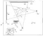
- FIG. 1shows one embodiment of a shape characterization system 100 useful to characterize a body 102 , that includes a navigation computer 104 , a position tracking device 106 , a plurality of cameras 108 - 1 through 108 -M, and a plurality of backgrounds 110 - 1 through 110 -N.
- the shape characterization system 100locates the position and orientation of the body 102 in space with respect to a global coordinate system 112 established by the navigation computer 104 .
- the shape characterization systemdetermines the position and orientation of body axes X B 114 , Y B 116 , and Z B 118 that are local to the body 102 with respect to the global coordinate system 112 established by the navigation computer 104 .
- the position and orientation of the body axes 114 , 116 , and 118 determined by the shape characterization system 100can be expressed as a linear transformation matrix that maps points on the body 102 in the local coordinate space defined by the body axes 114 , 116 , and 118 to points in the global coordinate system 112 .
- the position tracking device 106has a local coordinate system 120 , and each of the cameras 108 - 1 through 108 -M have their own local coordinate systems 122 - 1 through 122 -M.
- Suitable devices for use as the cameras 108 - 1 through 108 -Minclude known digital video cameras, digital still cameras, image capture devices and the like.
- the position tracking device 106has a predetermined and fixed relationship to the body 102 and is calibrated to the computer navigation system 104 . Furthermore, the position tracking device 106 is capable of tracking the position of a fixed point 124 on the surface of the body 102 with respect to either the coordinate system 120 of the position tracking device 106 or with respect to the coordinate system 112 of the navigation computer 104 because the two coordinate systems are calibrated to one another. The calibration of the two coordinate systems enables any measurements of the point 124 on the body 102 with respect to the coordinate system 120 of the position tracking device 106 to be mapped to the coordinate system 112 of the navigation computer 104 through a linear transformation.
- the position tracking device 106can be physically separate from the body 102 , or alternatively, the position tracking device 106 can be attached to or otherwise incorporated into the body 102 and still provide the necessary position information.
- the point 124can be located in a fixed position relative to the position tracking device 106 or can be determined by a calibration method described hereinafter.
- the point 124can be the location of an emitter used by the position tracking device 106 , as is discussed hereinafter.
- the position tracking device 106can be one of any of a number of position sensing devices known to those familiar with the art.
- FIG. 2 ashows the use of an example of the position tracking device 200 that uses an optical position sensor 204 .
- Tracking a body using the optical position sensor 204entails placing an emitter 206 on the body 102 , wherein the emitter 206 is an emissive light (visible or infrared) source.
- multiple emitters 206can be affixed to the body 102 in known configurations.
- the optical position sensor 206uses a light sensor 208 tuned to detect the light emitted by the light source and track the emissive light source 206 as it moves with the body 102 .
- a light emitting diodeis a typical emissive light source 206 and a charge coupled device (CCD) is a typical light sensor 208 .
- the FlashPoint system of Stryker Corporation(Kalamazoo, Mich.) is an example of the optical tracking system as shown in FIG. 2 a.
- FIG. 2 bshows the use of another type of an optical position tracking device 210 that makes use of another type of optical position sensor 212 .
- Tracking a body with this alternate optical position tracking device 210entails affixing a reflective body (e.g., a retro-reflector) 214 on the body 102 .
- An emissive light source 216is aligned with the reflective body 214 such that a beam of light 218 generated by the emissive light source 216 reflects off the reflective body 214 in such a manner that a light sensor 220 in the optical position sensor 212 may thereafter detect it and thus track the position of the reflective body 214 as it moves with the body 102 .
- the Motus system by Peak Performance Technologies, Inc.is a manufacturer of position measurement devices as shown in FIG. 2 b.
- FIG. 2 cshows the use of a position tracking device 224 that uses magnets 226 affixed to the body 102 .
- the changes in the direction and amplitude of magnetic flux of the magnets 226 as the magnets 226 move with the body 102are sensed by the magnetic position sensor 228 and used to determine the position of the magnets 226 .
- Examples of manufactures of this type of tracking technologyare Polhemus Incorporated of Colchester, Vt., and Ascension Technology Corporation of Burlington, Vt.
- the shape characterization systemidentifies the orientation of the axes X B , Y B , and Z B of the body 102 denoted as items numbered 114 , 116 , and 118 , respectively, with respect to the global coordinate system 112 by estimating a bounding volume of the body 102 and determining the axes of the bounding volume. Specifically, an axis of interest 114 , 116 , or 118 of the body 102 can be determined through an analysis of the estimated bounding volume. It follows that the remaining axes are normal to the determined axis and to one another.
- the orientation of the remaining axismay be determined more precisely by analyzing the position information provided by the tracking device and the estimated bounding volume.
- One point 124 of particular interestis a tip 126 of the body 102 .
- the tip 126can be located coaxially with the axis of interest (for example, the body axis X B 114 ) or located at some other point not on the axis of interest.
- the plurality of cameras 108 - 1 through 108 -M positioned around the bodycapture images of the body from different perspectives. These cameras 108 - 1 through 108 -M may be either fixed image cameras or video cameras, or some combination of the two camera technologies. If video cameras are used then individual frames of the video captured by the video camera are processed as single images. Preferably, all of the cameras capture frames nearly synchronously in time so that images from multiple view points are correlated.
- the positions and coordinate systems 122 - 1 through 122 -M of the cameras 108 - 1 and 108 -Mare calibrated to one another and to the global coordinate system 112 established by the navigation computer 104 .
- One embodiment of the method of calibration of the camerasis described herein below.
- the cameras 108 - 1 through 108 -Mare standard video cameras with frame capture hardware in desktop personal computers or Firewire and USB based cameras that are well known in the art.
- Fixed backgrounds 110 - 1 through 110 -Npreferably are positioned around the body opposite the cameras. These backgrounds 110 - 1 through 110 -N provide a known surround in an image captured by the cameras 108 - 1 through 108 -M that aids in identifying the edges of the body 102 in the image.
- the backgrounds 110 - 1 through 110 -Mmay be neutral, black, white, or any color that would increase the contrast between the portion of the image that represents the background 110 - 1 through 110 -M and the portion of the image that represents the body 102 . Further, the backgrounds may be backlit to further increase this contrast. It is possible to perform one embodiment of the method of the present invention without fixed backgrounds. However, this is not preferred because of the increased complexity of the shape determination from having to subtract the background image from the image of the body 102 .
- the navigation computer 104processes the images captured by the cameras 108 - 1 through 108 -M.
- the navigation computer 104may make use of a body database 130 populated with shape information regarding typical bodies that the navigation computer 104 may have to identify.
- the shape information of a body in the body database 130is preferably coordinates of vertex points of the body as are typically be available from a computer aided design system.
- the navigation computer 104develops one or more comparison metrics by comparing the bounding volume estimated from processing the images from the cameras 108 - 1 through 108 -M to the shape information that is stored in the body database 130 .
- the navigation computermay use the shape information for the body to refine the estimated bounding volume. For example, the navigation computer may develop a comparison metric by analyzing the distances between each vertex of the estimated bounding volume and a corresponding vertex stored as part of the shape information for a body in the body database 130 .
- a comparison metricis the result of analyzing the properties of the inertia moment axes of the estimated bounding volume with the inertia moment axes of a body in the body database 130 . Additional comparison metrics are known to those familiar with the art.
- a preferred embodimentuses a plurality of comparison metrics to determine the degree of correlation between the estimated bounding volume and a body stored in the body database 130 .
- the cameras 108 - 1 through 108 -Mit is not necessary for the cameras 108 - 1 through 108 -M to image the entire body. Only the portion of the body 102 that is of interest needs to be imaged by the cameras 108 - 1 through 108 -M. Furthermore, the body 102 and the cameras 108 - 1 through 108 -M are preferably positioned with respect to one another so that the field of view of each camera captures approximately the same parts of the body.
- FIG. 3depicts a flow chart 300 of the steps used to estimate the bounding volume from the captured images.
- Each image 302 - 1 through 302 -M captured by a camera 108 - 1 through 108 -M respectively,is first rectified by blocks 304 - 1 through 304 -M. That is, the image is corrected for any known irregularities in the lens, normalized for the known focal length of the lens being used, adjusted for resolution of the camera, etc.
- Blocks 306 - 1 through 306 -Mprocess the rectified image generated by blocks 304 - 1 through 304 -M to isolate the representation of the body from the representation of the background in the image.
- Blocks 308 - 1 through 308 -Mperform an edge detection operation on the image of the isolated body generated by blocks 306 - 1 through 306 -M.
- the bounding pyramids calculated in this manner from each of the images 301 - 1 through 301 -M captured by the camerasare normalized by a block 312 based on the time of capture of that image and the location of the camera as provided by blocks 314 - 1 through 314 -M.
- Blocks 314 - 1 through 314 -Mfurther intersect all of the bounding pyramids with one another to a bounding volume of the body.
- a block 316combines the estimated bounding volume with the location of the body from the position tracking device as provided by the block 318 to estimate the position and orientation of the body. If the body database 130 is available to the navigation computer, block 316 compares the bounding volume to the shape information for all of the bodies contained therein. If a body in the body database 130 is found that has dimensions and shape that is within a predetermined tolerance with respect to the bounding volume, then the navigation computer uses the shape information for the body in the body database to refine the estimate of the bounding volume.
- the cameras 108capture images of the body 102 continuously (or as rapidly as the cameras can) and, as the body 102 is rotated, bounding pyramids from these additional images are intersected with a previously calculated bounding volume to refine the estimated bounding volume and the estimated orientation of the body 102 .
- FIG. 4shows an example of an initial estimate of a bounding volume 400 of the body 102 generated by using three cameras 108 - 1 , 108 - 2 , and 108 - 3 .
- the bounding volume of the body 102can be determined by any of a number of well known methods available for making this determination. Depending on the number of cameras 108 - 1 through 108 -M or views from a single camera 108 - 1 , as discussed hereinafter, the intersection of the combined bounding volumes begins to approximate the shape of the body 102 .
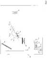
- FIG. 5shows another embodiment of the shape characterization system 500 wherein one camera 108 is used to capture a plurality of images of the body 102 as the body 102 rotates and moves through space, for example, along a path denoted by arrow R 502 .
- the blocks 304 through 318 of FIG. 3can process all of the images captured by the camera 108 of the body 102 as if a different camera captured each image from a different viewpoint relative to the body 102 .
- FIG. 6shows yet another embodiment of the shape characterization system 600 wherein the camera 108 simultaneously captures an image of the body 102 and of the reflection of the body 102 in a mirror 602 .
- the navigation computer 104processes the image captured by the camera 108 to divide the image into two images wherein one image contains the image of the body 102 and the other image contains the image of the reflection of the body 102 in the mirror 602 .
- the mirror 602acts as a second, albeit virtual, camera.
- the blocks 302 through 318 of the flowchart 300 depicted in FIG. 3act upon the image of the reflection of the body 102 in the mirror 602 as if the image had been captured by separate camera.
- more than one mirror 602could be employed.
- FIG. 7shows an example of such a calibration body 700 .
- FIG. 7 ashows a front view 702 of the calibration body 700 .
- FIG. 7 bshows a side view 704 of the calibration body 700 .
- FIG. 7 cshows a top view of the calibration body 706 .
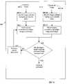
- FIG. 8depicts a flowchart 800 of the steps required to calibrate the cameras.
- Blocks 804 - 1 through 804 -Mrectify, isolate the body and identify edges of images 802 - 1 through 802 -M from each of the cameras, wherein each image 802 - 1 through 802 -M is an image of known perspective (e.g., front 702 , side 704 , and top 706 ) views of the calibration body 700 .
- Blocks 806 - 1 through 806 -Mestimate position and orientation of each camera 108 and apply corrections based on the position and orientation estimate to the edges generated by blocks 804 - 1 through 804 -M.
- a block 808compares the edges as corrected by blocks 806 - 1 through 806 -M with the known edge information of perspectives of the calibration body. If the corrected edges are within a predetermined tolerance of the known edges, then the cameras are said to have been calibrated and the position and orientation information generated by the block 806 is useable by the navigation computer 104 . If the corrected edges are outside of the predetermined tolerance of the known edges, then the difference between the corrected edges and the known edges is calculated by a block 810 and provided to the block 806 to refine the guess of the position and orientation of each camera. The blocks 806 , 808 , and 810 are repeated until all of the cameras 108 are calibrated.
- FIG. 9shows another embodiment of the shape characterization system 900 .
- this embodimentuses light sources 902 - 1 through 902 -M positioned with respect to sensors 904 - 1 through 904 -N.
- the positions of the light sources 902 - 1 through 902 -M and the sensors 904 - 1 through 904 -Nare in a predetermined fixed relation to each other and known to the navigation computer 104 .
- the navigation computer 104tracks the positions of all of the light sources 902 - 1 through 902 -M and all of the sensors 904 - 1 through 904 -N and can transform information from the sensors to be equivalent to information derived for a system wherein the position of the light sources 902 - 1 through 902 -M is in a fixed relation to the position of the sensors 940 - 1 through 904 -N.
- the navigation computer 104tracks changes in the position of either the light sources 902 - 1 through 902 -M or the sensors 904 - 1 through 904 -N.
- the light sources 902 - 1 through 902 -M and the sensors 904 - 1 through 904 -Nare positioned with respect to one another and the body 102 such that the body 102 occludes the light from each of the light sources 902 - 1 through 902 -M and causes a shadow to be cast upon one of the sensors 904 - 1 through 904 -N that is collinear with the light source 902 - 1 through 902 -M and the body 102 .
- the sensors 904 - 1 through 904 -Nare 2-dimensional sensing devices that are able to distinguish the regions that are in the shadow 906 - 1 through 906 -N of the body 102 from those regions that are not.
- Each of the sensors 904 - 1 through 904 -Nprovide information regarding the regions that are in shadow 906 - 1 through 906 -N to the navigation computer 104 . Only the shadows 906 - 1 through 906 -N of the portion of the body 102 that is of interest needs to fall upon the sensors 904 - 1 through 904 -N.
- a preferred sensor typeis a 2-dimensional charge coupled device (CCD) array. Such a CCD array typically produces an image that is comprised of pixels wherein each pixel corresponds to one CCD element of the 2-dimensional array.
- CCDcharge coupled device
- FIG. 10depicts a flow chart 925 of the steps used to estimate the bounding volume from the images generated by the sensors 904 - 1 through 904 -N.
- Each image 926 - 1 through 926 -N from each of the sensors 904 - 1 through 904 -Nis first rectified by blocks 928 - 1 through 928 -N. That is blocks 928 - 1 through 928 -N correct the image for any known irregularities in the sensor, adjusts the shadow information for the resolution of the sensor, etc.
- Blocks 930 - 1 through 930 -Nprocess the rectified images generated by blocks 928 - 1 through 928 -N to isolate the portions of the images that represent the shadow cast.
- Blocks 932 - 1 through 932 -Nperform an edge detection operation on the images of the isolated shadow generated by blocks 930 - 1 through 930 -N.
- Blocks 934 - 1 through 934 -Nuse the edge information generated by block 932 - 1 through 932 -N to estimate a general bounding pyramid with N faces for the body.
- the bounding pyramids calculated in this manner from the each of the images 926 - 1 through 926 -N generated by the sensorsare normalized by a block 936 based on the time of capture of that image and the location of the camera as provided by blocks 938 - 1 through 938 -N.
- the block 936further intersects all of the bounding pyramids with one another to a estimate bounding volume of the body.
- a block 940combines the estimated bounding volume with the location of the body from the position tracking device as provided by the block 942 to estimate the position and orientation of the body.
- Block 940uses shape information from the body database if it is available. Specifically, if a body in the body database 130 is found that has dimensions and shape that is within a predetermined tolerance with respect to the bounding volume, then the navigation computer 104 will use the shape information for the body in the body database to refine the estimate of the bounding volume.
- the sensors 904 - 1 through 904 -Ngenerate representations of the shadow 906 - 1 through 906 -N of the body 102 continuously (or as rapidly as the sensors can) and, as the body 102 is rotated, bounding pyramids from these additional representations are intersected with a previously calculated bounding volume to refine the estimated bounding volume and the estimated orientation of the body 102 .
- FIG. 11shows another embodiment of the shape characterization system 950 wherein one sensor 904 is used to generate a plurality images with representations of a shadow 906 of the body 102 as the body 102 moves through space while being illuminated by one light source 902 , for example, along a path denoted by arrow R 502 .
- the blocks 928 through 940 of FIG. 10can process all of the images generated by the sensor 904 of the body 102 as if a different sensor generated each image.
- the shadow sensing devicescan be calibrated using a body of known shape and dimension.
- a representative body 700 that can be used for calibrationis depicted in FIG. 7 a and the use of this body for calibrating the shadow sensing devices is the same as the process to calibrate the cameras described hereinabove except images from the shadow sensing devices 906 - 1 through 906 -N are used instead of images from cameras 108 .
- the algorithms used to estimate the shape of the body 102can be any of those well known and used in the field of computer graphics. Such algorithms are described in publications used in the field such as Computer Graphics: Principles and Practice , by James D. Foley, et al (Addison-Wesley, 1990), which is incorporated herein by reference. From the shape of the body 102 determined, the system can then determine the location of the tip 126 .
- the emitter 124 and the position tracking device 106are not necessary, because the image of the body (or the shadow of the body) for one of the multiple devices provides information about the relative position of the body 102 with respect to the other devices. This information can be used to deduce the position of the body 102 with respect to the coordinate system 112 of the navigation computer 104 by, for example, stereographically determining multiple homologous point pairs in at least two camera views of the body 102 .
- coloration and or texturecan also optionally be created by known methods.
- one or more light sources 128optionally can be simulated to shade the rendered view of the body 102 on a computer graphics screen.
Landscapes
- Physics & Mathematics (AREA)
- General Physics & Mathematics (AREA)
- Electromagnetism (AREA)
- Engineering & Computer Science (AREA)
- Radar, Positioning & Navigation (AREA)
- Remote Sensing (AREA)
- Length Measuring Devices By Optical Means (AREA)
- Measurement Of Length, Angles, Or The Like Using Electric Or Magnetic Means (AREA)
Abstract
Description
Claims (48)
Priority Applications (3)
| Application Number | Priority Date | Filing Date | Title |
|---|---|---|---|
| US11/050,920US7623250B2 (en) | 2005-02-04 | 2005-02-04 | Enhanced shape characterization device and method |
| DE102006005036.3ADE102006005036B4 (en) | 2005-02-04 | 2006-02-03 | Device and method for improved shape characterization |
| JP2006028557AJP2006258798A (en) | 2005-02-04 | 2006-02-06 | Device and method for improved shape characterization |
Applications Claiming Priority (1)
| Application Number | Priority Date | Filing Date | Title |
|---|---|---|---|
| US11/050,920US7623250B2 (en) | 2005-02-04 | 2005-02-04 | Enhanced shape characterization device and method |
Publications (2)
| Publication Number | Publication Date |
|---|---|
| US20060241404A1 US20060241404A1 (en) | 2006-10-26 |
| US7623250B2true US7623250B2 (en) | 2009-11-24 |
Family
ID=36848288
Family Applications (1)
| Application Number | Title | Priority Date | Filing Date |
|---|---|---|---|
| US11/050,920Active2027-06-15US7623250B2 (en) | 2005-02-04 | 2005-02-04 | Enhanced shape characterization device and method |
Country Status (3)
| Country | Link |
|---|---|
| US (1) | US7623250B2 (en) |
| JP (1) | JP2006258798A (en) |
| DE (1) | DE102006005036B4 (en) |
Cited By (18)
| Publication number | Priority date | Publication date | Assignee | Title |
|---|---|---|---|---|
| US20070297665A1 (en)* | 2004-11-01 | 2007-12-27 | Cognitens Ltd. | Method and System for Optical Edge Measurement |
| US20080193012A1 (en)* | 2005-03-16 | 2008-08-14 | Fujifilm Corporation | Apparatus and Method For Generating Catalog Image and Program Therefor |
| US8750568B2 (en) | 2012-05-22 | 2014-06-10 | Covidien Lp | System and method for conformal ablation planning |
| WO2015104062A1 (en) | 2014-01-13 | 2015-07-16 | Brainlab Ag | Estimation and compensation of tracking inaccuracies |
| US9161799B2 (en) | 2013-01-28 | 2015-10-20 | Warsaw Orthopedic, Inc. | Surgical implant system and method |
| US9439627B2 (en) | 2012-05-22 | 2016-09-13 | Covidien Lp | Planning system and navigation system for an ablation procedure |
| US9439622B2 (en) | 2012-05-22 | 2016-09-13 | Covidien Lp | Surgical navigation system |
| US9439623B2 (en) | 2012-05-22 | 2016-09-13 | Covidien Lp | Surgical planning system and navigation system |
| US9498182B2 (en) | 2012-05-22 | 2016-11-22 | Covidien Lp | Systems and methods for planning and navigation |
| US9830424B2 (en) | 2013-09-18 | 2017-11-28 | Hill-Rom Services, Inc. | Bed/room/patient association systems and methods |
| US9950194B2 (en) | 2014-09-09 | 2018-04-24 | Mevion Medical Systems, Inc. | Patient positioning system |
| US20180168769A1 (en)* | 2015-11-03 | 2018-06-21 | Michael Frank Gunter WOOD | Dual zoom and dual field-of-view microscope |
| US10531926B2 (en) | 2016-05-23 | 2020-01-14 | Mako Surgical Corp. | Systems and methods for identifying and tracking physical objects during a robotic surgical procedure |
| US11291507B2 (en) | 2018-07-16 | 2022-04-05 | Mako Surgical Corp. | System and method for image based registration and calibration |
| US20220262029A1 (en)* | 2019-05-16 | 2022-08-18 | Maxell, Ltd. | Image processing apparatus and image processing method |
| US11707329B2 (en) | 2018-08-10 | 2023-07-25 | Covidien Lp | Systems and methods for ablation visualization |
| US11911325B2 (en) | 2019-02-26 | 2024-02-27 | Hill-Rom Services, Inc. | Bed interface for manual location |
| US12444075B2 (en) | 2024-03-29 | 2025-10-14 | Maxell, Ltd. | Image processing apparatus and image processing method |
Families Citing this family (2)
| Publication number | Priority date | Publication date | Assignee | Title |
|---|---|---|---|---|
| JP2009509582A (en)* | 2005-09-22 | 2009-03-12 | スリーエム イノベイティブ プロパティズ カンパニー | Artifact reduction in 3D imaging |
| DE102016205469A1 (en)* | 2016-04-01 | 2017-10-05 | Wobben Properties Gmbh | Measuring system for measuring a surface |
Citations (151)
| Publication number | Priority date | Publication date | Assignee | Title |
|---|---|---|---|---|
| US3942522A (en) | 1973-10-19 | 1976-03-09 | National Research Development Corporation | Surgical splints and materials therefor |
| JPS5573253U (en) | 1978-11-14 | 1980-05-20 | ||
| JPS5581641U (en) | 1978-12-02 | 1980-06-05 | ||
| JPS5581640U (en) | 1978-11-30 | 1980-06-05 | ||
| JPS5594244U (en) | 1978-12-25 | 1980-06-30 | ||
| JPS55110539U (en) | 1979-01-29 | 1980-08-02 | ||
| JPS5645649Y2 (en) | 1976-08-31 | 1981-10-26 | ||
| JPS5721250Y2 (en) | 1974-01-11 | 1982-05-08 | ||
| JPS57122862U (en) | 1981-01-26 | 1982-07-30 | ||
| US4346717A (en) | 1979-09-07 | 1982-08-31 | Siemens Aktiengesellschaft | Device for punctuating internal body organs, vessels or the like |
| JPS57195447U (en) | 1981-06-08 | 1982-12-11 | ||
| US4370554A (en) | 1979-09-27 | 1983-01-25 | International Business Machines Corporation | Alignment system for particle beam lithography |
| US4416019A (en) | 1979-10-12 | 1983-11-15 | U.S. Philips Corporation | Device for producing images of a layer of an object from multiple shadow images with varying degrees of overlap |
| US4461016A (en) | 1979-10-03 | 1984-07-17 | U.S. Philips Corporation | Method of and device for forming an image of a layer of a three-dimensional object |
| JPS60185538U (en) | 1983-11-14 | 1985-12-09 | 村上 久 | Finger protection equipment when cooking |
| US4567896A (en) | 1984-01-20 | 1986-02-04 | Elscint, Inc. | Method and apparatus for calibrating a biopsy attachment for ultrasonic imaging apparatus |
| JPS6173308U (en) | 1984-10-19 | 1986-05-19 | ||
| JPS6125531Y2 (en) | 1981-03-19 | 1986-08-01 | ||
| JPS6131129Y2 (en) | 1981-06-05 | 1986-09-10 | ||
| US4673352A (en) | 1985-01-10 | 1987-06-16 | Markus Hansen | Device for measuring relative jaw positions and movements |
| JPS6257784B2 (en) | 1981-11-30 | 1987-12-02 | Yoshida Kogyo Kk | |
| US4722056A (en) | 1986-02-18 | 1988-01-26 | Trustees Of Dartmouth College | Reference display systems for superimposing a tomagraphic image onto the focal plane of an operating microscope |
| US4757379A (en) | 1986-04-14 | 1988-07-12 | Contour Dynamics | Apparatus and method for acquisition of 3D images |
| JPS6353511B2 (en) | 1981-01-26 | 1988-10-24 | Toyo Boseki | |
| JPS6359610B2 (en) | 1982-08-24 | 1988-11-21 | ||
| US4836778A (en) | 1987-05-26 | 1989-06-06 | Vexcel Corporation | Mandibular motion monitoring system |
| JPH01236046A (en) | 1988-03-17 | 1989-09-20 | Kenichirou Sugita | Head surgery support device and surgical site indication device |
| JPH01245108A (en) | 1988-03-28 | 1989-09-29 | Nissan Motor Co Ltd | Calibration method of workpiece positioning device |
| US4873651A (en) | 1987-04-21 | 1989-10-10 | Case Western Reserve University | Method and apparatus for reconstructing three-dimensional surfaces from two-dimensional images |
| JPH01288250A (en) | 1988-05-16 | 1989-11-20 | Toshiba Corp | surgical support equipment |
| US4908656A (en) | 1988-01-21 | 1990-03-13 | Nikon Corporation | Method of dimension measurement for a pattern formed by exposure apparatus, and method for setting exposure conditions and for inspecting exposure precision |
| US4972836A (en) | 1989-12-18 | 1990-11-27 | General Electric Company | Motion detector for high-resolution magnetic resonance imaging |
| JPH03155837A (en) | 1989-11-14 | 1991-07-03 | Yokogawa Medical Syst Ltd | Position setting method |
| JPH0332649Y2 (en) | 1983-01-28 | 1991-07-11 | ||
| JPH0357466B2 (en) | 1982-09-02 | 1991-09-02 | Process Shizai | |
| JPH03210245A (en) | 1989-11-15 | 1991-09-13 | George S Allen | Method and apparatus for imaging tissue body |
| US5050608A (en) | 1988-07-12 | 1991-09-24 | Medirand, Inc. | System for indicating a position to be operated in a patient's body |
| JPH0373113B2 (en) | 1987-08-31 | 1991-11-20 | Dx Antenna | |
| JPH04161145A (en) | 1990-10-26 | 1992-06-04 | Hitachi Ltd | Biomeasuring instrument |
| US5142930A (en) | 1987-11-10 | 1992-09-01 | Allen George S | Interactive image-guided surgical system |
| EP0501812A2 (en) | 1991-03-01 | 1992-09-02 | General Electric Company | Simulated surgery using display list surface data |
| US5155435A (en) | 1991-08-08 | 1992-10-13 | The Regents Of The University Of California | Method and apparatus for performing interventional medical procedures using MR imaging of interventional device superimposed with ghost patient image |
| US5172331A (en) | 1989-12-18 | 1992-12-15 | Fujitsu Limited | Apparatus and method for effecting exposure of sample to charged particle beam |
| US5186174A (en) | 1987-05-21 | 1993-02-16 | G. M. Piaff | Process and device for the reproducible optical representation of a surgical operation |
| JPH057554Y2 (en) | 1988-01-27 | 1993-02-25 | ||
| JPH058010Y2 (en) | 1984-12-03 | 1993-03-01 | ||
| US5197476A (en) | 1989-03-16 | 1993-03-30 | Christopher Nowacki | Locating target in human body |
| US5198877A (en) | 1990-10-15 | 1993-03-30 | Pixsys, Inc. | Method and apparatus for three-dimensional non-contact shape sensing |
| EP0535552A1 (en) | 1991-10-04 | 1993-04-07 | Carl Zeiss | Headband for measuring, lighting or viewing device |
| US5206893A (en) | 1989-06-30 | 1993-04-27 | Yokogawa Medical Systems, Limited | Radiotherapeutic apparatus having three dimensional light marks |
| US5207681A (en) | 1987-10-26 | 1993-05-04 | Neurodynamics, Inc. | Drill guide apparatus for perpendicular perforation of the cranium |
| JPH05111886A (en) | 1991-10-21 | 1993-05-07 | Yaskawa Electric Corp | Method for teaching calibration points of robot manipulator and working method for calibration |
| US5222499A (en) | 1989-11-15 | 1993-06-29 | Allen George S | Method and apparatus for imaging the anatomy |
| JPH0549644B2 (en) | 1981-08-28 | 1993-07-26 | Nestle Sa | |
| US5230623A (en) | 1991-12-10 | 1993-07-27 | Radionics, Inc. | Operating pointer with interactive computergraphics |
| US5251127A (en) | 1988-02-01 | 1993-10-05 | Faro Medical Technologies Inc. | Computer-aided surgery apparatus |
| US5276337A (en) | 1991-10-31 | 1994-01-04 | International Business Machines Corporation | Accuracy of alignment and O/L measurement systems by means of tunable source and handling of signal |
| JPH0619710B2 (en) | 1983-12-20 | 1994-03-16 | 日本電気株式会社 | Register control method |
| US5299288A (en) | 1990-05-11 | 1994-03-29 | International Business Machines Corporation | Image-directed robotic system for precise robotic surgery including redundant consistency checking |
| US5305203A (en) | 1988-02-01 | 1994-04-19 | Faro Medical Technologies Inc. | Computer-aided surgery apparatus |
| US5309913A (en) | 1992-11-30 | 1994-05-10 | The Cleveland Clinic Foundation | Frameless stereotaxy system |
| JPH06149950A (en) | 1992-06-10 | 1994-05-31 | Amei Technol Inc | Method and apparatus for manufacturing ordered fixing tool |
| JPH06205793A (en) | 1993-07-14 | 1994-07-26 | Toshiba Corp | 3D viewer system for surgery |
| JPH0663033B2 (en) | 1986-12-26 | 1994-08-17 | 川崎製鉄株式会社 | Manufacturing method of thin grain-oriented silicon steel sheet with little iron loss deterioration |
| JPH06251038A (en) | 1993-03-01 | 1994-09-09 | Toshiba Corp | Medical diagnosis support system |
| JPH0638975Y2 (en) | 1989-10-13 | 1994-10-12 | ナショナル住宅産業株式会社 | Roof structure |
| US5383454A (en) | 1990-10-19 | 1995-01-24 | St. Louis University | System for indicating the position of a surgical probe within a head on an image of the head |
| US5389101A (en) | 1992-04-21 | 1995-02-14 | University Of Utah | Apparatus and method for photogrammetric surgical localization |
| US5393988A (en) | 1988-11-04 | 1995-02-28 | Fujitsu Limited | Mask and charged particle beam exposure method using the mask |
| US5394875A (en) | 1993-10-21 | 1995-03-07 | Lewis; Judith T. | Automatic ultrasonic localization of targets implanted in a portion of the anatomy |
| US5400428A (en) | 1992-05-13 | 1995-03-21 | Spectranetics Corporation | Method and apparatus for linearly scanning energy over an optical fiber array and coupler for coupling energy to the optical fiber array |
| US5422491A (en) | 1988-11-04 | 1995-06-06 | Fujitsu Limited | Mask and charged particle beam exposure method using the mask |
| JPH07194616A (en) | 1993-11-26 | 1995-08-01 | Toshiba Medical Eng Co Ltd | Surgery support system |
| US5447154A (en) | 1992-07-31 | 1995-09-05 | Universite Joseph Fourier | Method for determining the position of an organ |
| JPH07236633A (en) | 1994-03-01 | 1995-09-12 | Toshiba Corp | Biopsy needle positioning method |
| JPH07303651A (en) | 1994-05-13 | 1995-11-21 | Olympus Optical Co Ltd | Medical control system |
| JPH07308303A (en) | 1994-05-17 | 1995-11-28 | Hitachi Ltd | Device for measurement position determination in biological function measurement |
| JPH07313527A (en) | 1994-05-27 | 1995-12-05 | Shimadzu Corp | Position display device for surgical instruments |
| JPH0753160Y2 (en) | 1989-05-15 | 1995-12-06 | オンキヨー株式会社 | Cassette frame rotating device |
| JPH07323035A (en) | 1994-05-31 | 1995-12-12 | Shimadzu Corp | Position display device for surgical instruments |
| JPH07328016A (en) | 1994-06-14 | 1995-12-19 | Olympus Optical Co Ltd | Surgical manipulator system |
| JPH0838506A (en) | 1994-05-21 | 1996-02-13 | Carl Zeiss:Fa | Method for correlating different coordinate systems to each other in computer-assisted stereotaxy |
| JPH0838439A (en) | 1994-07-28 | 1996-02-13 | Hitachi Medical Corp | Light marker for medical image diagnostic device and magnetic resonance imaging device having it |
| JPH0838507A (en) | 1994-07-28 | 1996-02-13 | Shimadzu Corp | Position display device for surgical instruments |
| JPH0824233B2 (en) | 1987-11-16 | 1996-03-06 | 三洋電機株式会社 | Electronic component mounting device |
| JPH0810266Y2 (en) | 1990-04-06 | 1996-03-29 | 東洋農機株式会社 | Shredder for beet pulp |
| JPH08107893A (en) | 1994-10-07 | 1996-04-30 | Hitachi Medical Corp | Medical image diagnostic apparatus with height adjusting function |
| US5512946A (en) | 1994-01-31 | 1996-04-30 | Hitachi Denshi Kabushiki Kaisha | Digital video signal processing device and TV camera device arranged to use it |
| JPH08112240A (en) | 1994-10-14 | 1996-05-07 | Olympus Optical Co Ltd | Medical care system |
| US5517990A (en) | 1992-11-30 | 1996-05-21 | The Cleveland Clinic Foundation | Stereotaxy wand and tool guide |
| JPH08150129A (en) | 1994-11-30 | 1996-06-11 | Agency Of Ind Science & Technol | Living body measuring reference point setting method and device |
| JPH08173449A (en) | 1994-05-07 | 1996-07-09 | Carl Zeiss:Fa | Method to operate microscope for operation |
| WO1996011624A3 (en) | 1994-10-07 | 1996-07-18 | Univ St Louis | Surgical navigation systems including reference and localization frames |
| JPH08215211A (en) | 1995-02-16 | 1996-08-27 | Hitachi Ltd | Remote surgery support device and method |
| JPH08224255A (en) | 1994-11-28 | 1996-09-03 | Donald W Chakeres | Medical auxiliary equipment |
| JPH08238257A (en) | 1995-01-26 | 1996-09-17 | Cleveland Clinic Found:The | Stereo taxi system and stereo taxi method |
| JPH08238248A (en) | 1995-03-06 | 1996-09-17 | Keiyuukai Moriya Keiyuu Biyouin | CT guide puncture needle puncture angle and puncture point determiner and puncture needle supporter |
| US5564437A (en) | 1992-12-15 | 1996-10-15 | Universite Joseph Fourier | Method and system for determining the fixation point on the femur of a crossed ligament of the knee |
| WO1996032059A1 (en) | 1995-04-10 | 1996-10-17 | Compass International Incorporated | Magnetic field digitizer for stereotactic surgery |
| JPH08275206A (en) | 1995-03-31 | 1996-10-18 | Fuji Photo Optical Co Ltd | Stereoscopic image display device |
| US5591207A (en) | 1995-03-30 | 1997-01-07 | Linvatec Corporation | Driving system for inserting threaded suture anchors |
| JPH0919441A (en) | 1995-07-04 | 1997-01-21 | Toshiba Corp | Image display device for surgical technique support |
| US5617857A (en) | 1995-06-06 | 1997-04-08 | Image Guided Technologies, Inc. | Imaging system having interactive medical instruments and methods |
| US5622170A (en) | 1990-10-19 | 1997-04-22 | Image Guided Technologies, Inc. | Apparatus for determining the position and orientation of an invasive portion of a probe inside a three-dimensional body |
| US5637866A (en)* | 1994-05-05 | 1997-06-10 | Riener; Karl S. | Apparatus and method for optically detecting and electronically analyzing the location of a projectile in a target plane |
| US5662111A (en) | 1991-01-28 | 1997-09-02 | Cosman; Eric R. | Process of stereotactic optical navigation |
| US5676673A (en) | 1994-09-15 | 1997-10-14 | Visualization Technology, Inc. | Position tracking and imaging system with error detection for use in medical applications |
| US5732703A (en) | 1992-11-30 | 1998-03-31 | The Cleveland Clinic Foundation | Stereotaxy wand and tool guide |
| US5740222A (en) | 1993-11-26 | 1998-04-14 | Kabushiki Kaisha Toshiba | Radiation computed tomography apparatus |
| US5772594A (en) | 1995-10-17 | 1998-06-30 | Barrick; Earl F. | Fluoroscopic image guided orthopaedic surgery system with intraoperative registration |
| US5797924A (en) | 1993-11-02 | 1998-08-25 | Loma Linda University Medical Center | Stereotactic fixation system and calibration phantom |
| US5807256A (en) | 1993-03-01 | 1998-09-15 | Kabushiki Kaisha Toshiba | Medical information processing system for supporting diagnosis |
| US5878103A (en) | 1997-06-30 | 1999-03-02 | Siemens Corporate Research, Inc. | Adaptive detector masking for speed-up of cone beam reconstruction |
| US5876325A (en) | 1993-11-02 | 1999-03-02 | Olympus Optical Co., Ltd. | Surgical manipulation system |
| US5880846A (en) | 1997-07-09 | 1999-03-09 | Yeda Research And Development Co. Ltd. | Method and apparatus for color-coded optical profilometer |
| US5891034A (en) | 1990-10-19 | 1999-04-06 | St. Louis University | System for indicating the position of a surgical probe within a head on an image of the head |
| US5921992A (en) | 1997-04-11 | 1999-07-13 | Radionics, Inc. | Method and system for frameless tool calibration |
| US6006126A (en)* | 1991-01-28 | 1999-12-21 | Cosman; Eric R. | System and method for stereotactic registration of image scan data |
| WO2000004506A1 (en) | 1998-07-20 | 2000-01-27 | Geometrix, Inc. | Method and system for generating fully-textured 3-d models |
| US6021343A (en) | 1997-11-20 | 2000-02-01 | Surgical Navigation Technologies | Image guided awl/tap/screwdriver |
| US6081336A (en) | 1997-09-26 | 2000-06-27 | Picker International, Inc. | Microscope calibrator |
| US6112113A (en) | 1997-07-03 | 2000-08-29 | U.S. Philips Corporation | Image-guided surgery system |
| US6167295A (en) | 1991-01-28 | 2000-12-26 | Radionics, Inc. | Optical and computer graphic stereotactic localizer |
| WO2001000092A1 (en) | 1999-06-25 | 2001-01-04 | Ddi Direct Digital Imaging Gmbh | Digital x-ray scanning apparatus |
| US6175415B1 (en) | 1997-02-19 | 2001-01-16 | United Technologies Corporation | Optical profile sensor |
| US6181815B1 (en) | 1997-02-25 | 2001-01-30 | Nec Corporation | Subject image extraction device |
| WO2001011553A1 (en) | 1999-08-10 | 2001-02-15 | Ajax Cooke Pty Ltd | Item recognition method and apparatus |
| US6226003B1 (en) | 1998-08-11 | 2001-05-01 | Silicon Graphics, Inc. | Method for rendering silhouette and true edges of 3-D line drawings with occlusion |
| US6285902B1 (en) | 1999-02-10 | 2001-09-04 | Surgical Insights, Inc. | Computer assisted targeting device for use in orthopaedic surgery |
| US6301498B1 (en) | 1998-04-17 | 2001-10-09 | Cornell Research Foundation, Inc. | Method of determining carotid artery stenosis using X-ray imagery |
| US6306126B1 (en) | 1998-09-18 | 2001-10-23 | Stryker Leibinger Gmbh & Co Kg | Calibrating device |
| US6317139B1 (en) | 1998-03-25 | 2001-11-13 | Lance Williams | Method and apparatus for rendering 3-D surfaces from 2-D filtered silhouettes |
| US6356272B1 (en) | 1996-08-29 | 2002-03-12 | Sanyo Electric Co., Ltd. | Texture information giving method, object extracting method, three-dimensional model generating method and apparatus for the same |
| US6455835B1 (en) | 2001-04-04 | 2002-09-24 | International Business Machines Corporation | System, method, and program product for acquiring accurate object silhouettes for shape recovery |
| US6512844B2 (en) | 1997-05-30 | 2003-01-28 | California Institute Of Technology | 3D rendering |
| US6535219B1 (en) | 2000-03-30 | 2003-03-18 | Intel Corporation | Method and apparatus to display objects in a computer system |
| US6567156B1 (en) | 1998-10-29 | 2003-05-20 | Sarin Technologies Ltd. | Apparatus and method for examining the shape of gemstones |
| US20030164953A1 (en) | 2002-03-01 | 2003-09-04 | Thomas Bauch | Operation lamp with camera system for 3D referencing |
| US20030195526A1 (en) | 2002-04-16 | 2003-10-16 | Stefan Vilsmeier | Marker for an instrument and methods for localizing a marker |
| US6662036B2 (en)* | 1991-01-28 | 2003-12-09 | Sherwood Services Ag | Surgical positioning system |
| US20040013305A1 (en)* | 2001-11-14 | 2004-01-22 | Achi Brandt | Method and apparatus for data clustering including segmentation and boundary detection |
| US20040170247A1 (en) | 2002-08-05 | 2004-09-02 | Ian Poole | Displaying image data using automatic presets |
| US20040171922A1 (en) | 2001-07-06 | 2004-09-02 | Jean-Michel Rouet | Image processing method for interacting with a 3-d surface represented in a 3-d image |
| US20040170308A1 (en) | 2003-02-27 | 2004-09-02 | Igor Belykh | Method for automated window-level settings for magnetic resonance images |
| US6788827B1 (en) | 1999-09-30 | 2004-09-07 | Koninklijke Philips Electronics N.V. | Image processing method and system for following a moving object from one image to an other image sequence |
| US6788062B2 (en) | 2002-07-25 | 2004-09-07 | Stryker Leibinger Gmbh & Co., Kg | Correcting geometry and intensity distortions in MR data |
| US20040175034A1 (en) | 2001-06-20 | 2004-09-09 | Rafael Wiemker | Method for segmentation of digital images |
| US6792074B2 (en) | 2001-03-05 | 2004-09-14 | Brainlab Ag | Method for producing or updating radiotherapy plan |
| US20040181144A1 (en) | 1997-03-11 | 2004-09-16 | Aesculap Ag & Co. Kg | Process and device for the preoperative determination of the positioning data of endoprosthetic parts |
| US20040181149A1 (en) | 2001-02-07 | 2004-09-16 | Ulrich Langlotz | Device and method for intraoperative navigation |
| US20060036148A1 (en)* | 2004-07-23 | 2006-02-16 | Grimm James E | Navigated surgical sizing guide |
Family Cites Families (12)
| Publication number | Priority date | Publication date | Assignee | Title |
|---|---|---|---|---|
| JPS5786368A (en)* | 1980-11-19 | 1982-05-29 | Hitachi Medical Corp | Body contour display device for radiotherapy plan |
| US6973202B2 (en) | 1998-10-23 | 2005-12-06 | Varian Medical Systems Technologies, Inc. | Single-camera tracking of an object |
| JP2002543411A (en)* | 1999-04-30 | 2002-12-17 | ワグナー,クリストフ | Optical detection method of object shape |
| JP2001061861A (en)* | 1999-06-28 | 2001-03-13 | Siemens Ag | System and medical workstation with image capturing means |
| US6288785B1 (en)* | 1999-10-28 | 2001-09-11 | Northern Digital, Inc. | System for determining spatial position and/or orientation of one or more objects |
| JP3433204B2 (en) | 2000-04-27 | 2003-08-04 | 株式会社東北テクノアーチ | 3D model construction device |
| JP2002031507A (en)* | 2000-07-14 | 2002-01-31 | Tokyo Denki Univ | 3D image measurement device |
| JP2002098521A (en) | 2000-09-26 | 2002-04-05 | Minolta Co Ltd | Three-dimensional contour data producing device |
| JP2003065736A (en) | 2001-08-24 | 2003-03-05 | Sanyo Electric Co Ltd | 3D modeling equipment |
| JP3941631B2 (en)* | 2002-08-16 | 2007-07-04 | 富士ゼロックス株式会社 | Three-dimensional imaging apparatus and method |
| GB2410328B (en)* | 2002-08-29 | 2006-06-07 | Cyberoptics Corp | Multiple source alignment sensor with improved optics |
| DE10254942B3 (en)* | 2002-11-25 | 2004-08-12 | Siemens Ag | Method for automatically determining the coordinates of images of marks in a volume data set and medical device |
- 2005
- 2005-02-04USUS11/050,920patent/US7623250B2/enactiveActive
- 2006
- 2006-02-03DEDE102006005036.3Apatent/DE102006005036B4/enactiveActive
- 2006-02-06JPJP2006028557Apatent/JP2006258798A/enactivePending
Patent Citations (175)
| Publication number | Priority date | Publication date | Assignee | Title |
|---|---|---|---|---|
| US3942522A (en) | 1973-10-19 | 1976-03-09 | National Research Development Corporation | Surgical splints and materials therefor |
| JPS5721250Y2 (en) | 1974-01-11 | 1982-05-08 | ||
| JPS5645649Y2 (en) | 1976-08-31 | 1981-10-26 | ||
| JPS5573253U (en) | 1978-11-14 | 1980-05-20 | ||
| JPS5581640U (en) | 1978-11-30 | 1980-06-05 | ||
| JPS5581641U (en) | 1978-12-02 | 1980-06-05 | ||
| JPS5594244U (en) | 1978-12-25 | 1980-06-30 | ||
| JPS55110539U (en) | 1979-01-29 | 1980-08-02 | ||
| US4346717A (en) | 1979-09-07 | 1982-08-31 | Siemens Aktiengesellschaft | Device for punctuating internal body organs, vessels or the like |
| US4370554A (en) | 1979-09-27 | 1983-01-25 | International Business Machines Corporation | Alignment system for particle beam lithography |
| US4461016A (en) | 1979-10-03 | 1984-07-17 | U.S. Philips Corporation | Method of and device for forming an image of a layer of a three-dimensional object |
| US4416019A (en) | 1979-10-12 | 1983-11-15 | U.S. Philips Corporation | Device for producing images of a layer of an object from multiple shadow images with varying degrees of overlap |
| JPS57122862U (en) | 1981-01-26 | 1982-07-30 | ||
| JPS6353511B2 (en) | 1981-01-26 | 1988-10-24 | Toyo Boseki | |
| JPS6125531Y2 (en) | 1981-03-19 | 1986-08-01 | ||
| JPS6131129Y2 (en) | 1981-06-05 | 1986-09-10 | ||
| JPS57195447U (en) | 1981-06-08 | 1982-12-11 | ||
| JPH0549644B2 (en) | 1981-08-28 | 1993-07-26 | Nestle Sa | |
| JPS6257784B2 (en) | 1981-11-30 | 1987-12-02 | Yoshida Kogyo Kk | |
| JPS6359610B2 (en) | 1982-08-24 | 1988-11-21 | ||
| JPH0357466B2 (en) | 1982-09-02 | 1991-09-02 | Process Shizai | |
| JPH0332649Y2 (en) | 1983-01-28 | 1991-07-11 | ||
| JPS60185538U (en) | 1983-11-14 | 1985-12-09 | 村上 久 | Finger protection equipment when cooking |
| JPH0619710B2 (en) | 1983-12-20 | 1994-03-16 | 日本電気株式会社 | Register control method |
| US4567896A (en) | 1984-01-20 | 1986-02-04 | Elscint, Inc. | Method and apparatus for calibrating a biopsy attachment for ultrasonic imaging apparatus |
| JPS6173308U (en) | 1984-10-19 | 1986-05-19 | ||
| JPH058010Y2 (en) | 1984-12-03 | 1993-03-01 | ||
| US4673352A (en) | 1985-01-10 | 1987-06-16 | Markus Hansen | Device for measuring relative jaw positions and movements |
| US4722056A (en) | 1986-02-18 | 1988-01-26 | Trustees Of Dartmouth College | Reference display systems for superimposing a tomagraphic image onto the focal plane of an operating microscope |
| US4757379A (en) | 1986-04-14 | 1988-07-12 | Contour Dynamics | Apparatus and method for acquisition of 3D images |
| JPH0663033B2 (en) | 1986-12-26 | 1994-08-17 | 川崎製鉄株式会社 | Manufacturing method of thin grain-oriented silicon steel sheet with little iron loss deterioration |
| US4873651A (en) | 1987-04-21 | 1989-10-10 | Case Western Reserve University | Method and apparatus for reconstructing three-dimensional surfaces from two-dimensional images |
| US5186174A (en) | 1987-05-21 | 1993-02-16 | G. M. Piaff | Process and device for the reproducible optical representation of a surgical operation |
| US4836778A (en) | 1987-05-26 | 1989-06-06 | Vexcel Corporation | Mandibular motion monitoring system |
| JPH0373113B2 (en) | 1987-08-31 | 1991-11-20 | Dx Antenna | |
| US5207681A (en) | 1987-10-26 | 1993-05-04 | Neurodynamics, Inc. | Drill guide apparatus for perpendicular perforation of the cranium |
| US5142930A (en) | 1987-11-10 | 1992-09-01 | Allen George S | Interactive image-guided surgical system |
| JPH0824233B2 (en) | 1987-11-16 | 1996-03-06 | 三洋電機株式会社 | Electronic component mounting device |
| US4908656A (en) | 1988-01-21 | 1990-03-13 | Nikon Corporation | Method of dimension measurement for a pattern formed by exposure apparatus, and method for setting exposure conditions and for inspecting exposure precision |
| JPH057554Y2 (en) | 1988-01-27 | 1993-02-25 | ||
| US5251127A (en) | 1988-02-01 | 1993-10-05 | Faro Medical Technologies Inc. | Computer-aided surgery apparatus |
| US5305203A (en) | 1988-02-01 | 1994-04-19 | Faro Medical Technologies Inc. | Computer-aided surgery apparatus |
| JPH01236046A (en) | 1988-03-17 | 1989-09-20 | Kenichirou Sugita | Head surgery support device and surgical site indication device |
| JPH01245108A (en) | 1988-03-28 | 1989-09-29 | Nissan Motor Co Ltd | Calibration method of workpiece positioning device |
| JPH01288250A (en) | 1988-05-16 | 1989-11-20 | Toshiba Corp | surgical support equipment |
| US5050608A (en) | 1988-07-12 | 1991-09-24 | Medirand, Inc. | System for indicating a position to be operated in a patient's body |
| US5393988A (en) | 1988-11-04 | 1995-02-28 | Fujitsu Limited | Mask and charged particle beam exposure method using the mask |
| US5422491A (en) | 1988-11-04 | 1995-06-06 | Fujitsu Limited | Mask and charged particle beam exposure method using the mask |
| US5197476A (en) | 1989-03-16 | 1993-03-30 | Christopher Nowacki | Locating target in human body |
| JPH0753160Y2 (en) | 1989-05-15 | 1995-12-06 | オンキヨー株式会社 | Cassette frame rotating device |
| US5206893A (en) | 1989-06-30 | 1993-04-27 | Yokogawa Medical Systems, Limited | Radiotherapeutic apparatus having three dimensional light marks |
| JPH0638975Y2 (en) | 1989-10-13 | 1994-10-12 | ナショナル住宅産業株式会社 | Roof structure |
| JPH03155837A (en) | 1989-11-14 | 1991-07-03 | Yokogawa Medical Syst Ltd | Position setting method |
| JPH03210245A (en) | 1989-11-15 | 1991-09-13 | George S Allen | Method and apparatus for imaging tissue body |
| US5222499A (en) | 1989-11-15 | 1993-06-29 | Allen George S | Method and apparatus for imaging the anatomy |
| US5172331A (en) | 1989-12-18 | 1992-12-15 | Fujitsu Limited | Apparatus and method for effecting exposure of sample to charged particle beam |
| JPH03193040A (en) | 1989-12-18 | 1991-08-22 | General Electric Co <Ge> | Device for determining the movement of anatomical specimens |
| US4972836A (en) | 1989-12-18 | 1990-11-27 | General Electric Company | Motion detector for high-resolution magnetic resonance imaging |
| JPH0810266Y2 (en) | 1990-04-06 | 1996-03-29 | 東洋農機株式会社 | Shredder for beet pulp |
| US5299288A (en) | 1990-05-11 | 1994-03-29 | International Business Machines Corporation | Image-directed robotic system for precise robotic surgery including redundant consistency checking |
| US5198877A (en) | 1990-10-15 | 1993-03-30 | Pixsys, Inc. | Method and apparatus for three-dimensional non-contact shape sensing |
| US5383454A (en) | 1990-10-19 | 1995-01-24 | St. Louis University | System for indicating the position of a surgical probe within a head on an image of the head |
| US5851183A (en) | 1990-10-19 | 1998-12-22 | St. Louis University | System for indicating the position of a surgical probe within a head on an image of the head |
| US5383454B1 (en) | 1990-10-19 | 1996-12-31 | Univ St Louis | System for indicating the position of a surgical probe within a head on an image of the head |
| US5891034A (en) | 1990-10-19 | 1999-04-06 | St. Louis University | System for indicating the position of a surgical probe within a head on an image of the head |
| US5622170A (en) | 1990-10-19 | 1997-04-22 | Image Guided Technologies, Inc. | Apparatus for determining the position and orientation of an invasive portion of a probe inside a three-dimensional body |
| US5419320A (en) | 1990-10-26 | 1995-05-30 | Hitachi, Ltd. | Method and apparatus for obtaining an image indicating metabolism in a body |
| JPH04161145A (en) | 1990-10-26 | 1992-06-04 | Hitachi Ltd | Biomeasuring instrument |
| US6006126A (en)* | 1991-01-28 | 1999-12-21 | Cosman; Eric R. | System and method for stereotactic registration of image scan data |
| US5662111A (en) | 1991-01-28 | 1997-09-02 | Cosman; Eric R. | Process of stereotactic optical navigation |
| US6662036B2 (en)* | 1991-01-28 | 2003-12-09 | Sherwood Services Ag | Surgical positioning system |
| US6167295A (en) | 1991-01-28 | 2000-12-26 | Radionics, Inc. | Optical and computer graphic stereotactic localizer |
| US5848967A (en) | 1991-01-28 | 1998-12-15 | Cosman; Eric R. | Optically coupled frameless stereotactic system and method |
| EP0501812A2 (en) | 1991-03-01 | 1992-09-02 | General Electric Company | Simulated surgery using display list surface data |
| JPH05184554A (en) | 1991-08-08 | 1993-07-27 | Univ California | Method and device for achieving intervening medical procedure using magnetic resonance imaging of intervening device superposed on ghost patent image |
| US5155435A (en) | 1991-08-08 | 1992-10-13 | The Regents Of The University Of California | Method and apparatus for performing interventional medical procedures using MR imaging of interventional device superimposed with ghost patient image |
| US5412811A (en) | 1991-10-04 | 1995-05-09 | Carl-Zeiss-Stiftung | Headgear having a holding device for holding an instrument |
| EP0535552A1 (en) | 1991-10-04 | 1993-04-07 | Carl Zeiss | Headband for measuring, lighting or viewing device |
| JPH05111886A (en) | 1991-10-21 | 1993-05-07 | Yaskawa Electric Corp | Method for teaching calibration points of robot manipulator and working method for calibration |
| US5276337A (en) | 1991-10-31 | 1994-01-04 | International Business Machines Corporation | Accuracy of alignment and O/L measurement systems by means of tunable source and handling of signal |
| US5230623A (en) | 1991-12-10 | 1993-07-27 | Radionics, Inc. | Operating pointer with interactive computergraphics |
| US5389101A (en) | 1992-04-21 | 1995-02-14 | University Of Utah | Apparatus and method for photogrammetric surgical localization |
| US5400428A (en) | 1992-05-13 | 1995-03-21 | Spectranetics Corporation | Method and apparatus for linearly scanning energy over an optical fiber array and coupler for coupling energy to the optical fiber array |
| US5365996A (en) | 1992-06-10 | 1994-11-22 | Amei Technologies Inc. | Method and apparatus for making customized fixation devices |
| JPH06149950A (en) | 1992-06-10 | 1994-05-31 | Amei Technol Inc | Method and apparatus for manufacturing ordered fixing tool |
| US5447154A (en) | 1992-07-31 | 1995-09-05 | Universite Joseph Fourier | Method for determining the position of an organ |
| US5517990A (en) | 1992-11-30 | 1996-05-21 | The Cleveland Clinic Foundation | Stereotaxy wand and tool guide |
| US5732703A (en) | 1992-11-30 | 1998-03-31 | The Cleveland Clinic Foundation | Stereotaxy wand and tool guide |
| US5309913A (en) | 1992-11-30 | 1994-05-10 | The Cleveland Clinic Foundation | Frameless stereotaxy system |
| US5564437A (en) | 1992-12-15 | 1996-10-15 | Universite Joseph Fourier | Method and system for determining the fixation point on the femur of a crossed ligament of the knee |
| JPH06251038A (en) | 1993-03-01 | 1994-09-09 | Toshiba Corp | Medical diagnosis support system |
| US5807256A (en) | 1993-03-01 | 1998-09-15 | Kabushiki Kaisha Toshiba | Medical information processing system for supporting diagnosis |
| US5787886A (en) | 1993-03-19 | 1998-08-04 | Compass International Incorporated | Magnetic field digitizer for stereotatic surgery |
| US6442416B1 (en) | 1993-04-22 | 2002-08-27 | Image Guided Technologies, Inc. | Determination of the position and orientation of at least one object in space |
| JPH06205793A (en) | 1993-07-14 | 1994-07-26 | Toshiba Corp | 3D viewer system for surgery |
| US5394875A (en) | 1993-10-21 | 1995-03-07 | Lewis; Judith T. | Automatic ultrasonic localization of targets implanted in a portion of the anatomy |
| JPH07255723A (en) | 1993-10-21 | 1995-10-09 | Judith T Lewis | Automatic ultrasonic wave fixing method of target implanted to one portion of human body |
| US5876325A (en) | 1993-11-02 | 1999-03-02 | Olympus Optical Co., Ltd. | Surgical manipulation system |
| US5797924A (en) | 1993-11-02 | 1998-08-25 | Loma Linda University Medical Center | Stereotactic fixation system and calibration phantom |
| US5848126A (en) | 1993-11-26 | 1998-12-08 | Kabushiki Kaisha Toshiba | Radiation computed tomography apparatus |
| JPH07194616A (en) | 1993-11-26 | 1995-08-01 | Toshiba Medical Eng Co Ltd | Surgery support system |
| US5740222A (en) | 1993-11-26 | 1998-04-14 | Kabushiki Kaisha Toshiba | Radiation computed tomography apparatus |
| US5748696A (en) | 1993-11-26 | 1998-05-05 | Kabushiki Kaisha Toshiba | Radiation computed tomography apparatus |
| US5512946A (en) | 1994-01-31 | 1996-04-30 | Hitachi Denshi Kabushiki Kaisha | Digital video signal processing device and TV camera device arranged to use it |
| JPH07236633A (en) | 1994-03-01 | 1995-09-12 | Toshiba Corp | Biopsy needle positioning method |
| US5637866A (en)* | 1994-05-05 | 1997-06-10 | Riener; Karl S. | Apparatus and method for optically detecting and electronically analyzing the location of a projectile in a target plane |
| JPH08173449A (en) | 1994-05-07 | 1996-07-09 | Carl Zeiss:Fa | Method to operate microscope for operation |
| US5697368A (en) | 1994-05-07 | 1997-12-16 | Carl-Zeiss-Stiftung | Process for the operation of an operation microscope |
| JPH07303651A (en) | 1994-05-13 | 1995-11-21 | Olympus Optical Co Ltd | Medical control system |
| JPH07308303A (en) | 1994-05-17 | 1995-11-28 | Hitachi Ltd | Device for measurement position determination in biological function measurement |
| US5795294A (en) | 1994-05-21 | 1998-08-18 | Carl-Zeiss-Stiftung | Procedure for the correlation of different coordinate systems in computer-supported, stereotactic surgery |
| JPH0838506A (en) | 1994-05-21 | 1996-02-13 | Carl Zeiss:Fa | Method for correlating different coordinate systems to each other in computer-assisted stereotaxy |
| JPH07313527A (en) | 1994-05-27 | 1995-12-05 | Shimadzu Corp | Position display device for surgical instruments |
| JPH07323035A (en) | 1994-05-31 | 1995-12-12 | Shimadzu Corp | Position display device for surgical instruments |
| JPH07328016A (en) | 1994-06-14 | 1995-12-19 | Olympus Optical Co Ltd | Surgical manipulator system |
| JPH0838439A (en) | 1994-07-28 | 1996-02-13 | Hitachi Medical Corp | Light marker for medical image diagnostic device and magnetic resonance imaging device having it |
| JPH0838507A (en) | 1994-07-28 | 1996-02-13 | Shimadzu Corp | Position display device for surgical instruments |
| US5676673A (en) | 1994-09-15 | 1997-10-14 | Visualization Technology, Inc. | Position tracking and imaging system with error detection for use in medical applications |
| JPH08107893A (en) | 1994-10-07 | 1996-04-30 | Hitachi Medical Corp | Medical image diagnostic apparatus with height adjusting function |
| WO1996011624A3 (en) | 1994-10-07 | 1996-07-18 | Univ St Louis | Surgical navigation systems including reference and localization frames |
| JPH08112240A (en) | 1994-10-14 | 1996-05-07 | Olympus Optical Co Ltd | Medical care system |
| JPH08224255A (en) | 1994-11-28 | 1996-09-03 | Donald W Chakeres | Medical auxiliary equipment |
| US5690108A (en) | 1994-11-28 | 1997-11-25 | Chakeres; Donald W. | Interventional medicine apparatus |
| US5706811A (en) | 1994-11-30 | 1998-01-13 | Director-General Of Agency Of Industrial Science And Technology | Method and apparatus for setting reference point for organic measurement |
| JPH08150129A (en) | 1994-11-30 | 1996-06-11 | Agency Of Ind Science & Technol | Living body measuring reference point setting method and device |
| US5682890A (en) | 1995-01-26 | 1997-11-04 | Picker International, Inc. | Magnetic resonance stereotactic surgery with exoskeleton tissue stabilization |
| JPH08238257A (en) | 1995-01-26 | 1996-09-17 | Cleveland Clinic Found:The | Stereo taxi system and stereo taxi method |
| JPH08215211A (en) | 1995-02-16 | 1996-08-27 | Hitachi Ltd | Remote surgery support device and method |
| US5855553A (en) | 1995-02-16 | 1999-01-05 | Hitchi, Ltd. | Remote surgery support system and method thereof |
| JPH08238248A (en) | 1995-03-06 | 1996-09-17 | Keiyuukai Moriya Keiyuu Biyouin | CT guide puncture needle puncture angle and puncture point determiner and puncture needle supporter |
| US5591207A (en) | 1995-03-30 | 1997-01-07 | Linvatec Corporation | Driving system for inserting threaded suture anchors |
| JPH08275206A (en) | 1995-03-31 | 1996-10-18 | Fuji Photo Optical Co Ltd | Stereoscopic image display device |
| WO1996032059A1 (en) | 1995-04-10 | 1996-10-17 | Compass International Incorporated | Magnetic field digitizer for stereotactic surgery |
| US5617857A (en) | 1995-06-06 | 1997-04-08 | Image Guided Technologies, Inc. | Imaging system having interactive medical instruments and methods |
| JPH0919441A (en) | 1995-07-04 | 1997-01-21 | Toshiba Corp | Image display device for surgical technique support |
| US5772594A (en) | 1995-10-17 | 1998-06-30 | Barrick; Earl F. | Fluoroscopic image guided orthopaedic surgery system with intraoperative registration |
| US6356272B1 (en) | 1996-08-29 | 2002-03-12 | Sanyo Electric Co., Ltd. | Texture information giving method, object extracting method, three-dimensional model generating method and apparatus for the same |
| US6175415B1 (en) | 1997-02-19 | 2001-01-16 | United Technologies Corporation | Optical profile sensor |
| US6181815B1 (en) | 1997-02-25 | 2001-01-30 | Nec Corporation | Subject image extraction device |
| US20040181144A1 (en) | 1997-03-11 | 2004-09-16 | Aesculap Ag & Co. Kg | Process and device for the preoperative determination of the positioning data of endoprosthetic parts |
| US5921992A (en) | 1997-04-11 | 1999-07-13 | Radionics, Inc. | Method and system for frameless tool calibration |
| US6512844B2 (en) | 1997-05-30 | 2003-01-28 | California Institute Of Technology | 3D rendering |
| US5878103A (en) | 1997-06-30 | 1999-03-02 | Siemens Corporate Research, Inc. | Adaptive detector masking for speed-up of cone beam reconstruction |
| US6112113A (en) | 1997-07-03 | 2000-08-29 | U.S. Philips Corporation | Image-guided surgery system |
| US5880846A (en) | 1997-07-09 | 1999-03-09 | Yeda Research And Development Co. Ltd. | Method and apparatus for color-coded optical profilometer |
| US6081336A (en) | 1997-09-26 | 2000-06-27 | Picker International, Inc. | Microscope calibrator |
| US6021343A (en) | 1997-11-20 | 2000-02-01 | Surgical Navigation Technologies | Image guided awl/tap/screwdriver |
| US6317139B1 (en) | 1998-03-25 | 2001-11-13 | Lance Williams | Method and apparatus for rendering 3-D surfaces from 2-D filtered silhouettes |
| US6301498B1 (en) | 1998-04-17 | 2001-10-09 | Cornell Research Foundation, Inc. | Method of determining carotid artery stenosis using X-ray imagery |
| WO2000004506A1 (en) | 1998-07-20 | 2000-01-27 | Geometrix, Inc. | Method and system for generating fully-textured 3-d models |
| US6529192B1 (en) | 1998-07-20 | 2003-03-04 | Geometrix, Inc. | Method and apparatus for generating mesh models of 3D objects |
| US6226003B1 (en) | 1998-08-11 | 2001-05-01 | Silicon Graphics, Inc. | Method for rendering silhouette and true edges of 3-D line drawings with occlusion |
| US6306126B1 (en) | 1998-09-18 | 2001-10-23 | Stryker Leibinger Gmbh & Co Kg | Calibrating device |
| US6567156B1 (en) | 1998-10-29 | 2003-05-20 | Sarin Technologies Ltd. | Apparatus and method for examining the shape of gemstones |
| US6285902B1 (en) | 1999-02-10 | 2001-09-04 | Surgical Insights, Inc. | Computer assisted targeting device for use in orthopaedic surgery |
| WO2001000092A1 (en) | 1999-06-25 | 2001-01-04 | Ddi Direct Digital Imaging Gmbh | Digital x-ray scanning apparatus |
| EP1189537B1 (en) | 1999-06-25 | 2004-09-15 | DDI Direct Digital Imaging GmbH | Digital x-ray scanning apparatus |
| US6592033B2 (en) | 1999-08-10 | 2003-07-15 | Ajax Cooke Pty Ltd | Item recognition method and apparatus |
| WO2001011553A1 (en) | 1999-08-10 | 2001-02-15 | Ajax Cooke Pty Ltd | Item recognition method and apparatus |
| US6788827B1 (en) | 1999-09-30 | 2004-09-07 | Koninklijke Philips Electronics N.V. | Image processing method and system for following a moving object from one image to an other image sequence |
| US6535219B1 (en) | 2000-03-30 | 2003-03-18 | Intel Corporation | Method and apparatus to display objects in a computer system |
| US20040181149A1 (en) | 2001-02-07 | 2004-09-16 | Ulrich Langlotz | Device and method for intraoperative navigation |
| US6792074B2 (en) | 2001-03-05 | 2004-09-14 | Brainlab Ag | Method for producing or updating radiotherapy plan |
| US6455835B1 (en) | 2001-04-04 | 2002-09-24 | International Business Machines Corporation | System, method, and program product for acquiring accurate object silhouettes for shape recovery |
| US20040175034A1 (en) | 2001-06-20 | 2004-09-09 | Rafael Wiemker | Method for segmentation of digital images |
| US20040171922A1 (en) | 2001-07-06 | 2004-09-02 | Jean-Michel Rouet | Image processing method for interacting with a 3-d surface represented in a 3-d image |
| US20040013305A1 (en)* | 2001-11-14 | 2004-01-22 | Achi Brandt | Method and apparatus for data clustering including segmentation and boundary detection |
| EP1340470B1 (en) | 2002-03-01 | 2004-09-15 | BrainLAB AG | Operation theatre lighting device with camera system for three-dimensional referencing |
| US20030164953A1 (en) | 2002-03-01 | 2003-09-04 | Thomas Bauch | Operation lamp with camera system for 3D referencing |
| EP1354564B1 (en) | 2002-04-16 | 2004-09-15 | BrainLAB AG | Instrument marker and method for localizing a marker |
| US20030195526A1 (en) | 2002-04-16 | 2003-10-16 | Stefan Vilsmeier | Marker for an instrument and methods for localizing a marker |
| US6788062B2 (en) | 2002-07-25 | 2004-09-07 | Stryker Leibinger Gmbh & Co., Kg | Correcting geometry and intensity distortions in MR data |
| US20040170247A1 (en) | 2002-08-05 | 2004-09-02 | Ian Poole | Displaying image data using automatic presets |
| US20040170308A1 (en) | 2003-02-27 | 2004-09-02 | Igor Belykh | Method for automated window-level settings for magnetic resonance images |
| US20060036148A1 (en)* | 2004-07-23 | 2006-02-16 | Grimm James E | Navigated surgical sizing guide |
Non-Patent Citations (3)
| Title |
|---|
| Horstmann G.A. and H.F. Reinhandt (1994). "Micro-Stereometry: A Frameless Computerized Navigating System for Open Microsurgery." Computerized Medical Imaging & Graphics, 18(4): 229-33. |
| Phillips, R., W. J. Viant et al. (1995). "Image Guided Orthopaedic Surgery Design and Analysis." Transactions of the Institute of Measurement and Control. 17(5): 251-264. |
| Zamorano, L.J., L. Nolte et al. (1994). "Interactive Intraoperative Localization Using an Infrared-Base System." Stereotactic & Functional Neurosurgery. 63(1-4): 84-8. |
Cited By (31)
| Publication number | Priority date | Publication date | Assignee | Title |
|---|---|---|---|---|
| US20070297665A1 (en)* | 2004-11-01 | 2007-12-27 | Cognitens Ltd. | Method and System for Optical Edge Measurement |
| US8482743B2 (en)* | 2004-11-01 | 2013-07-09 | Cognitens Ltd. | Method and system for optical edge measurement |
| US20080193012A1 (en)* | 2005-03-16 | 2008-08-14 | Fujifilm Corporation | Apparatus and Method For Generating Catalog Image and Program Therefor |
| US7961942B2 (en)* | 2005-03-16 | 2011-06-14 | Fujifilm Corporation | Apparatus and method for generating catalog image and program therefor |
| US9439622B2 (en) | 2012-05-22 | 2016-09-13 | Covidien Lp | Surgical navigation system |
| US9439627B2 (en) | 2012-05-22 | 2016-09-13 | Covidien Lp | Planning system and navigation system for an ablation procedure |
| US9439623B2 (en) | 2012-05-22 | 2016-09-13 | Covidien Lp | Surgical planning system and navigation system |
| US9498182B2 (en) | 2012-05-22 | 2016-11-22 | Covidien Lp | Systems and methods for planning and navigation |
| US8750568B2 (en) | 2012-05-22 | 2014-06-10 | Covidien Lp | System and method for conformal ablation planning |
| US9161799B2 (en) | 2013-01-28 | 2015-10-20 | Warsaw Orthopedic, Inc. | Surgical implant system and method |
| US9956020B2 (en) | 2013-01-28 | 2018-05-01 | Warsaw Orthopedic, Inc. | Surgical implant system and method |
| US11011267B2 (en) | 2013-09-18 | 2021-05-18 | Hill-Rom Services, Inc. | Bed/room/patient association systems and methods |
| US9830424B2 (en) | 2013-09-18 | 2017-11-28 | Hill-Rom Services, Inc. | Bed/room/patient association systems and methods |
| US12354731B2 (en) | 2013-09-18 | 2025-07-08 | Hill-Rom Services, Inc. | Bed/room/patient association systems and methods |
| WO2015104062A1 (en) | 2014-01-13 | 2015-07-16 | Brainlab Ag | Estimation and compensation of tracking inaccuracies |
| US10064687B2 (en) | 2014-01-13 | 2018-09-04 | Brainlab Ag | Estimation and compensation of tracking inaccuracies |
| US9950194B2 (en) | 2014-09-09 | 2018-04-24 | Mevion Medical Systems, Inc. | Patient positioning system |
| US20180168769A1 (en)* | 2015-11-03 | 2018-06-21 | Michael Frank Gunter WOOD | Dual zoom and dual field-of-view microscope |
| US10828125B2 (en)* | 2015-11-03 | 2020-11-10 | Synaptive Medical (Barbados) Inc. | Dual zoom and dual field-of-view microscope |
| US11826208B2 (en) | 2015-11-03 | 2023-11-28 | Synaptive Medical Inc. | Dual zoom and dual field-of-view microscope |
| US11937881B2 (en) | 2016-05-23 | 2024-03-26 | Mako Surgical Corp. | Systems and methods for identifying and tracking physical objects during a robotic surgical procedure |
| US10531926B2 (en) | 2016-05-23 | 2020-01-14 | Mako Surgical Corp. | Systems and methods for identifying and tracking physical objects during a robotic surgical procedure |
| US11291507B2 (en) | 2018-07-16 | 2022-04-05 | Mako Surgical Corp. | System and method for image based registration and calibration |
| US11806090B2 (en) | 2018-07-16 | 2023-11-07 | Mako Surgical Corp. | System and method for image based registration and calibration |
| US12207891B2 (en) | 2018-08-10 | 2025-01-28 | Covidien Lp | Systems and methods for ablation visualization |
| US11707329B2 (en) | 2018-08-10 | 2023-07-25 | Covidien Lp | Systems and methods for ablation visualization |
| US11911325B2 (en) | 2019-02-26 | 2024-02-27 | Hill-Rom Services, Inc. | Bed interface for manual location |
| US12396907B2 (en) | 2019-02-26 | 2025-08-26 | Hill-Rom Services, Inc. | Bed interface for manual location |
| US11972591B2 (en)* | 2019-05-16 | 2024-04-30 | Maxell, Ltd. | Image processing apparatus and image processing method |
| US20220262029A1 (en)* | 2019-05-16 | 2022-08-18 | Maxell, Ltd. | Image processing apparatus and image processing method |
| US12444075B2 (en) | 2024-03-29 | 2025-10-14 | Maxell, Ltd. | Image processing apparatus and image processing method |
Also Published As
| Publication number | Publication date |
|---|---|
| DE102006005036A1 (en) | 2006-09-07 |
| JP2006258798A (en) | 2006-09-28 |
| US20060241404A1 (en) | 2006-10-26 |
| DE102006005036B4 (en) | 2023-05-25 |
Similar Documents
| Publication | Publication Date | Title |
|---|---|---|
| US7623250B2 (en) | Enhanced shape characterization device and method | |
| US11276225B2 (en) | Synthesizing an image from a virtual perspective using pixels from a physical imager array weighted based on depth error sensitivity | |
| US6243599B1 (en) | Methods, systems and computer program products for photogrammetric sensor position estimation | |
| US10073517B1 (en) | Position tracking system that exploits arbitrary configurations to determine loop closure | |
| CN106643699B (en) | Space positioning device and positioning method in virtual reality system | |
| Bouguet et al. | 3D photography using shadows in dual-space geometry | |
| CN103501688B (en) | The method and apparatus that point of fixation maps | |
| EP3125806B1 (en) | Quantitative three-dimensional imaging of surgical scenes | |
| US7170677B1 (en) | Stereo-measurement borescope with 3-D viewing | |
| JP4820285B2 (en) | Automatic alignment touch system and method | |
| US7190331B2 (en) | System and method for measuring the registration accuracy of an augmented reality system | |
| EP3076892B1 (en) | A medical optical tracking system | |
| CN110230983B (en) | Vibration-resisting optical three-dimensional positioning method and device | |
| US9671876B2 (en) | Perspective tracking system | |
| Canessa et al. | Calibrated depth and color cameras for accurate 3D interaction in a stereoscopic augmented reality environment | |
| WO2022144116A1 (en) | An augmented reality system, an augmented reality hmd, and augmented reality method and a computer program | |
| US20100045701A1 (en) | Automatic mapping of augmented reality fiducials | |
| US20040141156A1 (en) | Position and orientation sensing with a projector | |
| CN108257177B (en) | Positioning system and method based on spatial identification | |
| US10992928B1 (en) | Calibration system for concurrent calibration of device sensors | |
| CN112614231B (en) | Information display method and information display system | |
| EP3045932A1 (en) | Positioning system and method | |
| KR20190130407A (en) | Apparatus and method for omni-directional camera calibration | |
| KR101913179B1 (en) | Apparatus for Infrared sensing footing device, Method for TWO-DIMENSIONAL image detecting and program using the same | |
| JP5337409B2 (en) | Information presentation device |
Legal Events
| Date | Code | Title | Description |
|---|---|---|---|
| AS | Assignment | Owner name:STRYKER LEIBINGER GMBH & CO. KG., GERMANY Free format text:ASSIGNMENT OF ASSIGNORS INTEREST;ASSIGNORS:DE LA BARRERA, JOSE LUIS MOCTEZUMA;SCHULZ, WALDEAN A.;MALACKOWSKI, DONALD W.;REEL/FRAME:017026/0772;SIGNING DATES FROM 20050228 TO 20050304 | |
| STCF | Information on status: patent grant | Free format text:PATENTED CASE | |
| FPAY | Fee payment | Year of fee payment:4 | |
| AS | Assignment | Owner name:STRYKER EUROPEAN HOLDINGS I, LLC, MICHIGAN Free format text:NUNC PRO TUNC ASSIGNMENT;ASSIGNOR:STRYKER EUROPEAN HOLDINGS VI, LLC;REEL/FRAME:037153/0391 Effective date:20151008 Owner name:STRYKER EUROPEAN HOLDINGS VI, LLC, MICHIGAN Free format text:NUNC PRO TUNC ASSIGNMENT;ASSIGNOR:STRYKER LEIBINGER GMBH & CO. KG;REEL/FRAME:037152/0910 Effective date:20151008 | |
| FPAY | Fee payment | Year of fee payment:8 | |
| AS | Assignment | Owner name:STRYKER EUROPEAN OPERATIONS HOLDINGS LLC, MICHIGAN Free format text:CHANGE OF NAME;ASSIGNOR:STRYKER EUROPEAN HOLDINGS III, LLC;REEL/FRAME:052860/0716 Effective date:20190226 Owner name:STRYKER EUROPEAN HOLDINGS III, LLC, DELAWARE Free format text:NUNC PRO TUNC ASSIGNMENT;ASSIGNOR:STRYKER EUROPEAN HOLDINGS I, LLC;REEL/FRAME:052861/0001 Effective date:20200519 | |
| MAFP | Maintenance fee payment | Free format text:PAYMENT OF MAINTENANCE FEE, 12TH YEAR, LARGE ENTITY (ORIGINAL EVENT CODE: M1553); ENTITY STATUS OF PATENT OWNER: LARGE ENTITY Year of fee payment:12 | |
| AS | Assignment | Owner name:STRYKER EUROPEAN OPERATIONS HOLDINGS LLC, MICHIGAN Free format text:CHANGE OF ADDRESS;ASSIGNOR:STRYKER EUROPEAN OPERATIONS HOLDINGS LLC;REEL/FRAME:069730/0754 Effective date:20241217 |