US7622891B2 - Contact-less power transfer - Google Patents
Contact-less power transferDownload PDFInfo
- Publication number
- US7622891B2 US7622891B2US10/532,977US53297705AUS7622891B2US 7622891 B2US7622891 B2US 7622891B2US 53297705 AUS53297705 AUS 53297705AUS 7622891 B2US7622891 B2US 7622891B2
- Authority
- US
- United States
- Prior art keywords
- power
- coils
- coil
- power transfer
- primary unit
- Prior art date
- Legal status (The legal status is an assumption and is not a legal conclusion. Google has not performed a legal analysis and makes no representation as to the accuracy of the status listed.)
- Active, expires
Links
Images


Classifications
- H—ELECTRICITY
- H02—GENERATION; CONVERSION OR DISTRIBUTION OF ELECTRIC POWER
- H02J—CIRCUIT ARRANGEMENTS OR SYSTEMS FOR SUPPLYING OR DISTRIBUTING ELECTRIC POWER; SYSTEMS FOR STORING ELECTRIC ENERGY
- H02J50/00—Circuit arrangements or systems for wireless supply or distribution of electric power
- H02J50/10—Circuit arrangements or systems for wireless supply or distribution of electric power using inductive coupling
- H02J50/12—Circuit arrangements or systems for wireless supply or distribution of electric power using inductive coupling of the resonant type
- H—ELECTRICITY
- H02—GENERATION; CONVERSION OR DISTRIBUTION OF ELECTRIC POWER
- H02J—CIRCUIT ARRANGEMENTS OR SYSTEMS FOR SUPPLYING OR DISTRIBUTING ELECTRIC POWER; SYSTEMS FOR STORING ELECTRIC ENERGY
- H02J50/00—Circuit arrangements or systems for wireless supply or distribution of electric power
- H02J50/10—Circuit arrangements or systems for wireless supply or distribution of electric power using inductive coupling
Definitions
- This inventionrelates to a new device for transferring power in a contact-less fashion, for example electromagnetic induction.
- Today's inductively-chargeable portable devicesfor example the Braun Oral B Plak Control power toothbrush, must typically be precisely aligned with their charger in order to charge them. This precision is necessary so that the coil in the device is correctly aligned with the coil in the charger—the coils being, in effect, the two halves of a conventional power transformer.
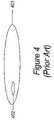
- FIG. 1Some examples of typical prior art are shown in FIG. 1 .
- the primary coil of the chargeris aligned with the secondary coil of the device.
- FIG. 1 ba horseshoe electromagnet on the charger is aligned with a similar electromagnet on the device.
- FIG. 1 coperates in a very similar way to FIG. 1 b : the field is created by two coils operating in antiphase (with the lower return circuit being an air gap), and the secondary coil is a flat wound coil.
- Prior artsuch as U.S. Pat. No. 4,873,677 works in such a fashion. Note in all cases the precise alignment that is required in order to achieve good coupling between the primary and secondary coils.
- FIG. 2 ashows some charger 201 with a surface 203 , the charger 201 emitting a field, and some device 202 charging from the charger 201 (and appreciating that in this figure the shapes of both are irrelevant).
- FIG. 2 bshows that the device 202 may move about on (“be translated relative to”) the surface 203 of the charger 201 in two directions, depicted X and Y, which are at right angles to one another. The device 202 may also move nearer to and further from the charger 201 in direction Z, but as this will eventually take it out of the charging field, and this is therefore not considered here.
- FIG. 2 cshows that in addition to the above translations, the device 202 may rotate around the X axis (rX), the Y axis (rY) and the Z axis (rZ). In the present application, only rotations about rZ, and not those around rX or rY, shall be considered. Each of these six translations and rotations is independent from (also known as “orthogonal to”) the others, and is known as a “degree of freedom”.
- FIG. 2 dshows an alternative translation co-ordinate system.
- the position of the device 202is determined by the radius (r) and the angle ( ⁇ ) from some centre point. Even though ⁇ involves rotation, it is still a translational degree of freedom, since the device 202 itself need not rotate about its own axis.
- a systemshould allow up to five degrees of freedom—translation in the Z axis not being of practical use—so that a device 202 can be placed without regard to its position or orientation on the charger 201 .
- FIG. 1 aoffers one degree of freedom (rotation in the plane of the coils), and those shown in FIG. 1 b and FIG. 1 c offer zero degrees of freedom, since if the device is to continue to receive adequate power it cannot be either rotated nor translated relative to the charger. Having zero—or only a few—degrees of freedom requires precise alignment which may be inconvenient to the user because it requires a degree of care and manual dexterity in placing the device 202 on the charger 201 .
- FIG. 4shows such a charger coil 401 and device coil 402 .
- Thisis the method adopted by various RFID devices.
- the coupling between the coils 401 and 402will be poor and highly variable dependent on position, so this solution is inefficient and limits the power that can be transferred while still complying with emission legislation. Therefore this solution is far from ideal in charging applications, where efficiency is typically an important criterion.
- Prior artincludes:
- FIG. 6which shows a laminar charger 601 generating a magnetic field in the plane of the charger 602 and a device 610 capable of receiving power from such a field when it is in a certain alignment 611 . If the field generated by the charger is made to rotate, as shown, then there is no requirement to align the device in any particular orientation.
- FIGS. 1A-1Cshow various configurations of primary and secondary coils.
- FIG. 2Ashows a device and charger.
- FIGS. 2B-2Dshow exemplary translation and rotational coordinate systems.
- FIG. 3shows exemplary coupling relationships.
- FIG. 4shows a charger coil and device coil that are not perfectly aligned.
- FIG. 5shows multiple charger coils and a single device coil.
- FIG. 6shows a laminar charger generating a magnetic field in the plane of the charger and a device capable of receiving power.
- FIGS. 7A-7Dshow different types of charger configurations which each have several sizes or shapes of coils.
- FIGS. 8A-8Bshow a system with a single rotational degree of freedom.
- FIGS. 9A-9Fshow various concentric charger and device configurations.
- FIGS. 10A-10Cshow various configurations where the primary charger coil is larger than the secondary device coil.
- FIG. 11Ashows a large primary coil with a small primary coil inside it.
- FIG. 11Bshows a device straddling an outer primary coil.
- FIGS. 12A-12Eshow possible indications.
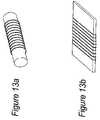
- FIGS. 13A-13Bshow possible core designs.
- a unit for transferring power in an inductive manner to at least one power-receiving devicethe unit being provided with at least one electrical coil, and the power-receiving device being capable of receiving power when placed in more than one position or rotation on the unit.
- the unitmay include a pad in which the coils are disposed, the pad serving as a surface upon which power-receiving devices may be placed in order to effect power transfer.
- the unitmay incorporate a power supply or be connectable to a power supply.
- the padis preferably a laminar pad, i.e. has a configuration of a lamina.
- the padis preferably generally flat, and may be substantially planar, it being understood that the pad may take a curved form or be made conformal to a curved surface such as the inside of a glove compartment in an automobile. This may apply also to the further aspects of the invention set out hereinbelow.
- a unit for transferring power in an inductive manner to at least one power-receiving devicethe unit being provided with a plurality of electrical coils, the electrical coils not all being of the same shape.
- the coilsmay be simple conductive loops, or may comprise a more complex arrangement of conductors. Where a more complex arrangement of conductors is provided, for example as disclosed in the present applicant's co-pending UK patent applications numbers 0210886.8 of 13 May 2002 and 0213024.3 of 7 Jun. 2002 (the full disclosures of which are hereby incorporated into the present application by reference), the term “coil” in the context of the present application is intended to denote each separate arrangement of conductors that defines a given charging region or active area on the primary unit and on which a secondary device is placed in order to effect charging.
- the plurality of electrical coilspreferably in this aspect may also not all be of the same size and/or not all enclose the same dimensional area.
- a unit for transferring power in an inductive manner to at least one power-receiving devicethe unit being provided with a plurality of electrical coils, the electrical coils not all being of the same size and/or not all enclosing the same dimensional area.
- all the coilsmay be of mutually different shapes and/or sizes and/or dimensional areas.
- two or more of the plurality of coilsmay have the same shape and/or size and/or dimensional area, with the remaining coils having one or more different shapes and/or sizes and/or dimensional areas, or all having the same different shape and/or size and/or dimensional area.
- the coilsmay be spatially separated from each other such that no coil is enclosed in or overlaps with any other coil.
- one or more smaller coilsmay be contained within a boundary of one or more larger coils.
- the coilsmay be substantially concentric, or may have some other arrangement.
- a plurality of smaller coilsmay be contained within a boundary of a larger coil in such a way that the smaller coils are not contained within each other or overlap with each other.
- Some smaller coilsmay be nested within each other within the boundary of a larger coil, with some other smaller coils not being nested within each other within the same outer boundary.
- the coilsmay take various shapes, including circular, elliptical, generally ovate, triangular, rectangular, parallelogram, trapezoidal, star-shaped, regular polygonal, irregular polygonal or amorphous.
- a unit for transferring power in an inductive manner to at least one power-receiving devicethe unit being provided with at least one plurality of nested electrical coils and also with means for selectively activating one or more of the nested electrical coils so as to be adaptable to provide efficient power transfer to power-receiving devices of different sizes and/or power requirements and/or positions/rotations.
- the means for selectively activating one or more of the nested coilsmay be adapted automatically to sense an appropriate size and/or power requirement and/or position/rotation determinant of the power-receiving unit (for example, a size or sizes of secondary power-receiving coils in the power-receiving device).
- the nested coilsmay be substantially circular, or may take any other appropriate shape as outlined above.
- nested sets of electrical coilseach having a substantially right-angled triangular shape, and arranged such that the right-angles of the four sets of coils all point towards a single origin point such that the four sets of nested coils have an overall substantially square or rectangular configuration.
- adjacent sets of coilsare driven in antiphase so as to cause rotation of a resultant electromagnetic field about the origin point, thereby providing a degree of rotational freedom in the positioning of a power-receiving device on the pad.
- a unit for transferring power in an inductive manner to at least one power-receiving devicethe unit being provided with an even number of electrical coils each having corner portion, the coils being arranged such that the corner portions all point towards an origin point, and wherein, in operation, adjacent coils are driven in antiphase so as to cause rotation of a resulting electromagnetic field about the origin point.
- coilswhich may each have a substantially right-angled triangle shape, a quarter circular shape or any other appropriate shape. Where more than four coils are provided, they may each have a generally triangular shape or take the shape of a sector of a circle.
- Any of the first to fourth aspects of the present inventionmay be combined with at least one power-receiving unit so as to form a system for contact-less power transfer.
- a system for contact-less power transfercomprising a power-transmitting unit provided with a primary coil and at least one power-receiving device incorporating a secondary coil, wherein the primary coil is generally elongate along an x-axis with respect to an orthogonal y-axis, and wherein the secondary coil is sized so as to be sufficiently similar in size to the primary coil with respect to the y-axis so as to provide efficient power transfer, but smaller in size with respect to the x-axis so as to provide a translational degree of freedom of movement along the x-axis.
- the primary coilmay be generally rectangular, or any other appropriate shape, including elliptical or generally ovate.
- the secondary coilpreferably has a corresponding rectangular (possibly square) or elliptical or ovate or other configuration, subject to the constraints that the extent of the primary coil along the y-axis is substantially similar to that of the secondary coil along the y-axis, and that the extent of the primary coil along the x-axis is greater than that of the secondary coil along the x-axis.
- the extent of the primary coil along the x-axisis at least twice, advantageously at least three or four times, that of the secondary coil along the x-axis.
- a system for contact-less power transfercomprising a power-transmitting unit provided with at least one primary coil having a boundary portion and at least one power-receiving device incorporating a secondary coil, wherein power transfer takes place by way of coupling of near-field flux flowing about the boundary portion of the at least one primary coil with windings of the secondary coil.
- the at least one primary coilmay be generally rectangular in shape, in which case there is one linear degree of freedom of movement of the secondary coil.
- the at least one primary coilmay be substantially circular or elliptical or the like, in which case a rotational degree of freedom of movement is provided.
- a system for contact-less power transfercomprising a power-transmitting unit provided with first and second substantially concentric primary coils, the first being larger than the second, and at least one power-receiving device incorporating at least one secondary coil dimensioned so as to correspond to a distance between the first and second primary coils, wherein power transfer takes place by way of coupling of near-field flux flowing about the boundaries of the first and second primary coils with generally opposed edges of the secondary coil.
- the first and second primary coils in this aspectare supplied with currents flowing in opposite directions.
- the coilsmay be generally circular, or may take any other appropriate shape as hereinbefore described.
- Embodiments of the present inventionmay therefore provide greater simplicity (and thus reduced cost) by offering a number of degrees of freedom which is less than that of GB 0210886.8, but greater than that of today's “toothbrush” chargers, while still preserving many of the benefits of GB 0210886.8 (Simplicity, Efficiency, Simultaneity and Universality).
- FIGS. 7 a , 7 b , 7 cshow three different types of charger configuration 701 which each have several sizes or shapes of coil 702 , 703 , 704 .
- Each coilcould be, for example, a multiply-wound coil of a type similar to that in FIG. 1 a .
- the coilsmay all be driven simultaneously, or only when a device is sensed.
- each coilis made clear by some indicator, allowing the user to place their device onto the coil which best couples to it, and in the correct orientation if such is necessary.
- the coilsare spatially separate (allowing multiple devices to be charged simultaneously), in FIG. 7 b they are concentric, and in FIG. 7 c they are a mixture of the two.
- the coilscan of course be of any shape to suit the device, and some examples are shown in FIG. 7 d.
- FIGS. 1 a and 8 ashow a prior art system with a single rotational degree of freedom—a coil on the primary 800 couples to a corresponding coil on the device 801 in the manner of a simple transformer.
- FIG. 8 bshows an alternative method of achieving the same rotational degree of freedom for a device 811 which expects a field in the manner of FIG. 1 c .
- An antiphase fieldis driven into sets of coils 810 A and 810 B such that the field rotates from being aligned in the 810 A axis to being aligned in the 810 B axis and back to 810 A.
- the devicereceives a significant amount of power no matter what its orientation.
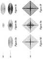
- FIG. 9extends these two means of generating a rotational degree of freedom by adding universality.
- a charger 901consists of a number of such coils, arranged concentrically, each of which can be driven independently. The charger behaves differently depending on which type of device is present 902 .
- FIGS. 9 d , 9 e , 9 fshow a charger with a coil configuration 903 of the type shown in FIG. 8 b , but again arranged concentrically as above, with similar benefits.
- FIG. 10shows various configurations in which the primary charger coil is larger than the secondary device coil, but constrained in its dimensions such that it offers a reasonably efficiency with a single translational degree of freedom in the X axis, and therefore the option of simultaneous charging of multiple devices.
- a rectangular charger coil 1001drives a smaller device coil 1002 by generating a field in the Z axis.
- a rectangular charger coil 1001drives a smaller device coil 1002 by generating a field in the Z axis.
- the device coil in the Y dimensionBy being similar in size to the device coil in the Y dimension, reasonable efficiency is obtained.
- By being significantly larger than the device coil in the X dimensionone degree of translational freedom is achieved.
- the coilscould be any type of shape (for example ellipsoidal) rather than rectangular as shown—an important point is the aspect ratio.
- FIGS. 10 b and 10 cachieve a similar result for devices of the FIG. 1 c type, 1003 .
- a charger coil identical to FIG. 10 ais used.
- FIG. 10 ait was be considered to be generating a net flux out from the centre of the coil in the Z dimension, but it can equally be viewed “up close” to the edge of the coil as generating a flux which is rotating around the wire(s), as shown in FIG. 10 b . Therefore if a device of FIG. 1 c is placed across any edge of the coil, it will receive the flux.
- FIG. 10 ca second coil is placed below the first 1004 . If placed along the boundary between the two, as shown, the device coil will receive power from each coil.
- this conceptcan be extended indefinitely in the Y dimension, as shown with a dotted line, to produce any number of lines along which a device may receive power.
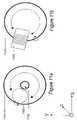
- FIG. 11 ashows a large coil 1101 with a small coil 1102 inside it.
- the coilscarry current in opposite directions, and so will generate a net flux flowing in the Z axis (out of the page). If a device with a coil 1103 is placed anywhere within the annulus formed between the coils, it will receive this flux with reasonable efficiency. Thus the device has a circular translational degree of freedom, and multiple devices can be placed on the charger.
- FIG. 11 bshows a similar scheme working with a device of FIG. 1 c type.
- the devicestraddles the outer coil 1101 to couple with it. This could be seen as a variant of FIG. 10 b.
- the chargermay sense if any device is present on any particular coil, and if so what its power needs are. Possible means for doing this include but are not limited to:
- the userhas limited degrees of freedom when placing devices. Therefore it may be advantageous to indicate these constraints to the user.
- the indicationsmay be rendered in any number of media, for example:
- the devicemay include corresponding indications.
- FIG. 12Some examples of possible indications are shown in FIG. 12 , which:
- any coils in the device and/or chargerwill have an effect on the efficiency and other characteristics.
- replacing any square coil with a circular coilmay reduce efficiency somewhat, but, thanks to the rotational symmetry of a circle, allows the device to have a rotational degree of freedom.
Landscapes
- Engineering & Computer Science (AREA)
- Computer Networks & Wireless Communication (AREA)
- Power Engineering (AREA)
- Charge And Discharge Circuits For Batteries Or The Like (AREA)
Abstract
Description
- A system is described in the Journal of the Magnetics Society of Japan titled “Coil Shape in a Desk-type Contactless Power Station System” (29Nov. 2001)
| Today's | Present | UK | ||
| chargers | invention | 0210886.8 | ||
| Simple | Y | Y | Y |
| (therefore cheap to make) | |||
| Efficient and uniform field | Y | Y | Y |
| (high-power within regulations) | |||
| Simultaneous | N | Y | Y |
| (more than one device at a time) | |||
| Universal | N | Y | Y |
| (many types of devices) | |||
| Degrees of freedom | 0 or | 0 . . . 2 of | 2 (X,Y) |
| (convenience) | 1 (rZ) | (X,Y,rZ) | 3 (X,Y, rZ) |
- 1. No degrees of freedom—the charger has different positions for different types of device (
FIG. 7 ) - 2. Only the rZ rotational degree of freedom, so the device has to be placed in the correct position on the charger. The charger has a single location with an effective coil size that alters with device needs (
FIG. 8 andFIG. 9 ) - 3. Only one translational degree of freedom (
FIG. 10 ), either:- a. Linear translational
- b. Circular translational, and rotational
- Addressing each of these categories in turn:
1. No Degrees of Freedom
- 1. No degrees of freedom—the charger has different positions for different types of device (
- In
FIG. 9 ano device is present, and so no charger coils are driven. - In
FIG. 9 ba physically small device with correspondingly small power requirements is present, and so only a few of the inner coils are driven. - In
FIG. 9 ca physically large device with correspondingly large power requirements is present, and so many of the coils are driven.
- In
- Sensing the resonance (“Q”) or other characteristics of the driven coils
- Communication by modulation of data signals onto the magnetic field (e.g. “back-scatter”, as used by RFID devices).
- For chargers with placement restrictions, indicating the correct device position by means of:
- Outlining of the coil area
- Filling, or patterning, the active coil area.
- For chargers with rotational restrictions, indicating the correct device rotation by means of:
- A line or arrow, or set of such.
- For chargers with placement restrictions, indicating the correct device position by means of:
- Printing ink, perhaps of a particular colour
- Raising or lowering the charger surface.
- Overall shape of the charger, or part of it.
FIG. 12 ashows a printed or raised outline of two devices, for chargers which have no degrees of freedom.FIG. 12 bshows a printed or raised arrow on both the charger and the device, for chargers with 2 translational but not rotational degrees of freedom.FIG. 12 cshows similar to12b, but with striped indication instead of arrows.FIG. 12 dshows a “target” of concentric circles on both charger and device, for chargers with only a rotational degree of freedom.FIG. 12 eshows a charger with one circular translational degree of freedom, designed such that the active area of the charger is obvious from its form.
- a rod of permeable material with wire coiled around it (
FIG. 13 a) or - a flat piece of permeable material with a wire coiled flat around it (
FIG. 13 b), as inFIG. 1 c.
- a rod of permeable material with wire coiled around it (
Claims (8)
Priority Applications (1)
| Application Number | Priority Date | Filing Date | Title |
|---|---|---|---|
| US12/339,509US8354821B2 (en) | 2002-10-28 | 2008-12-19 | Contact-less power transfer |
Applications Claiming Priority (3)
| Application Number | Priority Date | Filing Date | Title |
|---|---|---|---|
| GB0225013.2 | 2002-10-28 | ||
| GB0225013AGB2398176B (en) | 2002-05-13 | 2002-10-28 | Improvements relating to contact-less power transfer |
| PCT/GB2003/004654WO2004038888A2 (en) | 2002-10-28 | 2003-10-28 | Unit and system for contactless power transfer |
Related Child Applications (1)
| Application Number | Title | Priority Date | Filing Date |
|---|---|---|---|
| US12/339,509ContinuationUS8354821B2 (en) | 2002-10-28 | 2008-12-19 | Contact-less power transfer |
Publications (2)
| Publication Number | Publication Date |
|---|---|
| US20060061323A1 US20060061323A1 (en) | 2006-03-23 |
| US7622891B2true US7622891B2 (en) | 2009-11-24 |
Family
ID=32117243
Family Applications (2)
| Application Number | Title | Priority Date | Filing Date |
|---|---|---|---|
| US10/532,977Active2026-09-05US7622891B2 (en) | 2002-10-28 | 2003-10-28 | Contact-less power transfer |
| US12/339,509Expired - Fee RelatedUS8354821B2 (en) | 2002-10-28 | 2008-12-19 | Contact-less power transfer |
Family Applications After (1)
| Application Number | Title | Priority Date | Filing Date |
|---|---|---|---|
| US12/339,509Expired - Fee RelatedUS8354821B2 (en) | 2002-10-28 | 2008-12-19 | Contact-less power transfer |
Country Status (4)
| Country | Link |
|---|---|
| US (2) | US7622891B2 (en) |
| AU (1) | AU2003282214A1 (en) |
| DE (1) | DE10393604T5 (en) |
| WO (1) | WO2004038888A2 (en) |
Cited By (42)
| Publication number | Priority date | Publication date | Assignee | Title |
|---|---|---|---|---|
| US20080211314A1 (en)* | 2007-03-01 | 2008-09-04 | Graco Children's Products Inc. | Juvenile Product Inductive Power Transfer |
| US20100259217A1 (en)* | 2009-04-08 | 2010-10-14 | Access Business Group International Llc | Selectable coil array |
| US20110115433A1 (en)* | 2009-11-13 | 2011-05-19 | Samsung Electronics Co., Ltd. | Wireless charger for charging control and charging control method therefor |
| US20110234019A1 (en)* | 2007-08-17 | 2011-09-29 | Tmms Co., Ltd. | Method and device for transporting, distributing and managing electrical energy by remote longitudinal coupling in near field between electric dipoles |
| US8061864B2 (en) | 2009-05-12 | 2011-11-22 | Kimball International, Inc. | Furniture with wireless power |
| US20120007437A1 (en)* | 2007-08-28 | 2012-01-12 | Access Business Group International Llc | Inductive power supply |
| US20120056579A1 (en)* | 2010-09-08 | 2012-03-08 | Dong Zo Kim | Roof type charging apparatus using resonant power transmission |
| WO2012055443A1 (en) | 2010-10-29 | 2012-05-03 | 3E | System for contactless power transfer between nacelle and tower of a windturbine |
| US20120262005A1 (en)* | 2006-03-21 | 2012-10-18 | Murata Manufacturing Co., Ltd. | Device for transporting energy by partial influence through a dielectric medium |
| US8725330B2 (en) | 2010-06-02 | 2014-05-13 | Bryan Marc Failing | Increasing vehicle security |
| US20140191714A1 (en)* | 2013-01-04 | 2014-07-10 | Primax Electronics Ltd. | Wireless transmitting device for wireless charging |
| US9124308B2 (en) | 2009-05-12 | 2015-09-01 | Kimball International, Inc. | Furniture with wireless power |
| US20160204656A1 (en)* | 2014-12-20 | 2016-07-14 | Intel Corporation | Chassis Design for Wireless-Charging Coil Integration for Computing Systems |
| US9496081B2 (en) | 2011-04-08 | 2016-11-15 | Access Business Group International Llc | Counter wound inductive power supply |
| US9631950B2 (en) | 2011-08-05 | 2017-04-25 | Evatran Group, Inc. | Method and apparatus for aligning a vehicle with an inductive charging system |
| US9642219B2 (en) | 2014-06-05 | 2017-05-02 | Steelcase Inc. | Environment optimization for space based on presence and activities |
| US20170182903A1 (en)* | 2015-12-26 | 2017-06-29 | Intel Corporation | Technologies for wireless charging of electric vehicles |
| US20170225582A1 (en)* | 2014-10-29 | 2017-08-10 | Bayerische Motoren Werke Aktiengesellschaft | Method and Base Unit for Inductively Charging Electric and Hybrid Vehicles |
| US20170324450A1 (en)* | 2014-11-13 | 2017-11-09 | Lg Electronics Inc. | Wireless power transmission apparatus, wireless power reception apparatus, and wireless charging system |
| US9852388B1 (en) | 2014-10-03 | 2017-12-26 | Steelcase, Inc. | Method and system for locating resources and communicating within an enterprise |
| US9921726B1 (en) | 2016-06-03 | 2018-03-20 | Steelcase Inc. | Smart workstation method and system |
| US9955318B1 (en) | 2014-06-05 | 2018-04-24 | Steelcase Inc. | Space guidance and management system and method |
| US20180159305A1 (en)* | 2016-12-04 | 2018-06-07 | Lionel O. Barthold | Live-Line High Voltage Conductor Replacement |
| US10161752B1 (en) | 2014-10-03 | 2018-12-25 | Steelcase Inc. | Method and system for locating resources and communicating within an enterprise |
| US10253527B2 (en) | 2016-06-10 | 2019-04-09 | Steelcase Inc. | Smart locker |
| US10264213B1 (en) | 2016-12-15 | 2019-04-16 | Steelcase Inc. | Content amplification system and method |
| US10353664B2 (en) | 2014-03-07 | 2019-07-16 | Steelcase Inc. | Method and system for facilitating collaboration sessions |
| US10433646B1 (en) | 2014-06-06 | 2019-10-08 | Steelcaase Inc. | Microclimate control systems and methods |
| US10511191B2 (en) | 2015-07-09 | 2019-12-17 | Qualcomm Incorporated | Apparatus and methods for wireless power transmitter coil configuration |
| US10614694B1 (en) | 2014-06-06 | 2020-04-07 | Steelcase Inc. | Powered furniture assembly |
| US10733371B1 (en) | 2015-06-02 | 2020-08-04 | Steelcase Inc. | Template based content preparation system for use with a plurality of space types |
| US11133706B2 (en)* | 2015-07-28 | 2021-09-28 | Samsung Electronics Co., Ltd. | Wireless power transmitter |
| US11321643B1 (en) | 2014-03-07 | 2022-05-03 | Steelcase Inc. | Method and system for facilitating collaboration sessions |
| US11387680B2 (en)* | 2018-02-28 | 2022-07-12 | Massachusetts Institute Of Technology | Coreless power transformer |
| US11437852B2 (en)* | 2007-01-29 | 2022-09-06 | Powermat Technologies Ltd. | Pinless power coupling |
| US11437853B2 (en)* | 2015-12-07 | 2022-09-06 | Lapis Semiconductor Co., Ltd. | Power transmission apparatus and power transmission system |
| WO2022265877A1 (en)* | 2021-06-16 | 2022-12-22 | Resonant Link, Inc. | High efficiency wireless power transfer coils |
| US11581124B2 (en) | 2012-02-16 | 2023-02-14 | Auckland Uniservices Limited | Multiple coil flux pad |
| US11651891B2 (en) | 2009-08-07 | 2023-05-16 | Auckland Uniservices Limited | Roadway powered electric vehicle system |
| US11744376B2 (en) | 2014-06-06 | 2023-09-05 | Steelcase Inc. | Microclimate control systems and methods |
| US11984739B1 (en) | 2020-07-31 | 2024-05-14 | Steelcase Inc. | Remote power systems, apparatus and methods |
| US12118178B1 (en) | 2020-04-08 | 2024-10-15 | Steelcase Inc. | Wayfinding services method and apparatus |
Families Citing this family (220)
| Publication number | Priority date | Publication date | Assignee | Title |
|---|---|---|---|---|
| US7239110B2 (en)* | 2002-05-13 | 2007-07-03 | Splashpower Limited | Primary units, methods and systems for contact-less power transfer |
| CN101860089B (en) | 2005-07-12 | 2013-02-06 | 麻省理工学院 | wireless non-radiative energy transfer |
| US7825543B2 (en)* | 2005-07-12 | 2010-11-02 | Massachusetts Institute Of Technology | Wireless energy transfer |
| KR100819604B1 (en)* | 2005-07-27 | 2008-04-03 | 엘에스전선 주식회사 | Wireless Charger Decreased in Variation of Charging Efficiency |
| US7548040B2 (en)* | 2005-07-28 | 2009-06-16 | Zerog Wireless, Inc. | Wireless battery charging of electronic devices such as wireless headsets/headphones |
| GB0517082D0 (en)* | 2005-08-19 | 2005-09-28 | Univ City Hong Kong | Auxiliary winding for improved performance of a planar inductive charging platform |
| KR20080064986A (en)* | 2005-10-21 | 2008-07-10 | 더 리젠트스 오브 더 유니버시티 오브 콜로라도 | System and method for receiving and managing power in wireless devices |
| US7514899B2 (en) | 2005-11-18 | 2009-04-07 | Avago Technologies Ecbu Ip (Singapore) Pte. Ltd. | Method and apparatus for optical wireless charging |
| US20070114969A1 (en)* | 2005-11-22 | 2007-05-24 | Koninklijke Philips Electronic, N.V. | Magnetic electrical daisy connection for simultaneously recharging electronic devices |
| US8169185B2 (en) | 2006-01-31 | 2012-05-01 | Mojo Mobility, Inc. | System and method for inductive charging of portable devices |
| US7952322B2 (en) | 2006-01-31 | 2011-05-31 | Mojo Mobility, Inc. | Inductive power source and charging system |
| US11201500B2 (en) | 2006-01-31 | 2021-12-14 | Mojo Mobility, Inc. | Efficiencies and flexibilities in inductive (wireless) charging |
| WO2007122788A1 (en) | 2006-03-24 | 2007-11-01 | Kabushiki Kaisha Toshiba | Power receiving device, electronic apparatus using same and non-contact charger |
| US7976388B2 (en)* | 2006-03-24 | 2011-07-12 | Umagination Labs, L.P. | Oral care gaming system with electronic game |
| US8232764B2 (en)* | 2006-03-24 | 2012-07-31 | Kabushiki Kaisha Toshiba | Power receiving device, and electronic apparatus and non-contact charging system using the same |
| US7948208B2 (en) | 2006-06-01 | 2011-05-24 | Mojo Mobility, Inc. | Power source, charging system, and inductive receiver for mobile devices |
| US11329511B2 (en) | 2006-06-01 | 2022-05-10 | Mojo Mobility Inc. | Power source, charging system, and inductive receiver for mobile devices |
| JP4855150B2 (en)* | 2006-06-09 | 2012-01-18 | 株式会社トプコン | Fundus observation apparatus, ophthalmic image processing apparatus, and ophthalmic image processing program |
| DE102006027824A1 (en)* | 2006-06-16 | 2007-12-20 | Siemens Ag | Carrier unit e.g. desk top, for use in office, has control device connected with navigation device, and designed such that transmitting unit is activated corresponding to position of navigation device |
| US9129741B2 (en) | 2006-09-14 | 2015-09-08 | Qualcomm Incorporated | Method and apparatus for wireless power transmission |
| US8004235B2 (en) | 2006-09-29 | 2011-08-23 | Access Business Group International Llc | System and method for inductively charging a battery |
| EP2082468A2 (en)* | 2006-10-26 | 2009-07-29 | Koninklijke Philips Electronics N.V. | Floor covering and inductive power system |
| US20080165082A1 (en)* | 2007-01-05 | 2008-07-10 | Manico Joseph A | Function enhancing array for multi-frame display system |
| US7728551B2 (en)* | 2007-04-26 | 2010-06-01 | Visteon Global Technologies, Inc. | Wireless power transfer system |
| US9421388B2 (en) | 2007-06-01 | 2016-08-23 | Witricity Corporation | Power generation for implantable devices |
| US8115448B2 (en) | 2007-06-01 | 2012-02-14 | Michael Sasha John | Systems and methods for wireless power |
| FI120853B (en) | 2007-09-18 | 2010-03-31 | Powerkiss Oy | Energy transfer device and method |
| CA2701394A1 (en)* | 2007-10-17 | 2009-04-23 | Access Business Group International Llc | Laptop and portable electronic device wireless power supply systems |
| US8193769B2 (en)* | 2007-10-18 | 2012-06-05 | Powermat Technologies, Ltd | Inductively chargeable audio devices |
| US7915858B2 (en) | 2007-10-30 | 2011-03-29 | City University Of Hong Kong | Localized charging, load identification and bi-directional communication methods for a planar inductive battery charging system |
| US8228025B2 (en) | 2007-11-09 | 2012-07-24 | City University Of Hong Kong | Electronic control method for a planar inductive battery charging apparatus |
| JP2011514129A (en) | 2008-02-22 | 2011-04-28 | アクセス ビジネス グループ インターナショナル リミテッド ライアビリティ カンパニー | Induction power supply system with battery type detection function |
| US8421407B2 (en) | 2008-02-25 | 2013-04-16 | L & P Property Management Company | Inductively coupled work surfaces |
| US8228026B2 (en) | 2008-02-25 | 2012-07-24 | L & P Property Management Company | Inductively coupled shelving and storage containers |
| US8338990B2 (en) | 2008-03-13 | 2012-12-25 | Access Business Group International Llc | Inductive power supply system with multiple coil primary |
| US8229567B2 (en) | 2008-04-30 | 2012-07-24 | Medtronic, Inc. | Concentric primary coils for inductively charging an implantable medical device, external power source and method |
| US20110050164A1 (en) | 2008-05-07 | 2011-03-03 | Afshin Partovi | System and methods for inductive charging, and improvements and uses thereof |
| CN102099958B (en)* | 2008-05-14 | 2013-12-25 | 麻省理工学院 | Wireless power transfer including interference enhancement |
| US8193762B2 (en)* | 2008-07-22 | 2012-06-05 | General Electric Company | Battery charging apparatus of a wireless digital X-ray detector |
| US8248024B2 (en)* | 2008-08-15 | 2012-08-21 | Microsoft Corporation | Advanced inductive charging pad for portable devices |
| EP2161811A1 (en) | 2008-09-05 | 2010-03-10 | Koninklijke Philips Electronics N.V. | Inductive charger and charging method |
| US8669676B2 (en) | 2008-09-27 | 2014-03-11 | Witricity Corporation | Wireless energy transfer across variable distances using field shaping with magnetic materials to improve the coupling factor |
| US8466583B2 (en) | 2008-09-27 | 2013-06-18 | Witricity Corporation | Tunable wireless energy transfer for outdoor lighting applications |
| US8587153B2 (en) | 2008-09-27 | 2013-11-19 | Witricity Corporation | Wireless energy transfer using high Q resonators for lighting applications |
| US8772973B2 (en)* | 2008-09-27 | 2014-07-08 | Witricity Corporation | Integrated resonator-shield structures |
| US9093853B2 (en) | 2008-09-27 | 2015-07-28 | Witricity Corporation | Flexible resonator attachment |
| US8686598B2 (en) | 2008-09-27 | 2014-04-01 | Witricity Corporation | Wireless energy transfer for supplying power and heat to a device |
| US9246336B2 (en) | 2008-09-27 | 2016-01-26 | Witricity Corporation | Resonator optimizations for wireless energy transfer |
| US8933594B2 (en) | 2008-09-27 | 2015-01-13 | Witricity Corporation | Wireless energy transfer for vehicles |
| US8569914B2 (en) | 2008-09-27 | 2013-10-29 | Witricity Corporation | Wireless energy transfer using object positioning for improved k |
| US8957549B2 (en) | 2008-09-27 | 2015-02-17 | Witricity Corporation | Tunable wireless energy transfer for in-vehicle applications |
| US9160203B2 (en) | 2008-09-27 | 2015-10-13 | Witricity Corporation | Wireless powered television |
| US9744858B2 (en) | 2008-09-27 | 2017-08-29 | Witricity Corporation | System for wireless energy distribution in a vehicle |
| US8552592B2 (en)* | 2008-09-27 | 2013-10-08 | Witricity Corporation | Wireless energy transfer with feedback control for lighting applications |
| US8937408B2 (en) | 2008-09-27 | 2015-01-20 | Witricity Corporation | Wireless energy transfer for medical applications |
| US9105959B2 (en) | 2008-09-27 | 2015-08-11 | Witricity Corporation | Resonator enclosure |
| US8643326B2 (en)* | 2008-09-27 | 2014-02-04 | Witricity Corporation | Tunable wireless energy transfer systems |
| US8304935B2 (en)* | 2008-09-27 | 2012-11-06 | Witricity Corporation | Wireless energy transfer using field shaping to reduce loss |
| US8487480B1 (en) | 2008-09-27 | 2013-07-16 | Witricity Corporation | Wireless energy transfer resonator kit |
| US9577436B2 (en) | 2008-09-27 | 2017-02-21 | Witricity Corporation | Wireless energy transfer for implantable devices |
| US8963488B2 (en) | 2008-09-27 | 2015-02-24 | Witricity Corporation | Position insensitive wireless charging |
| US8629578B2 (en) | 2008-09-27 | 2014-01-14 | Witricity Corporation | Wireless energy transfer systems |
| US20100277121A1 (en)* | 2008-09-27 | 2010-11-04 | Hall Katherine L | Wireless energy transfer between a source and a vehicle |
| US8461722B2 (en) | 2008-09-27 | 2013-06-11 | Witricity Corporation | Wireless energy transfer using conducting surfaces to shape field and improve K |
| US8947186B2 (en) | 2008-09-27 | 2015-02-03 | Witricity Corporation | Wireless energy transfer resonator thermal management |
| US9515494B2 (en) | 2008-09-27 | 2016-12-06 | Witricity Corporation | Wireless power system including impedance matching network |
| US20120086284A1 (en)* | 2008-09-27 | 2012-04-12 | Capanella Andrew J | Wireless transmission of solar generated power |
| US9035499B2 (en) | 2008-09-27 | 2015-05-19 | Witricity Corporation | Wireless energy transfer for photovoltaic panels |
| US8497601B2 (en) | 2008-09-27 | 2013-07-30 | Witricity Corporation | Wireless energy transfer converters |
| US8471410B2 (en) | 2008-09-27 | 2013-06-25 | Witricity Corporation | Wireless energy transfer over distance using field shaping to improve the coupling factor |
| US8324759B2 (en)* | 2008-09-27 | 2012-12-04 | Witricity Corporation | Wireless energy transfer using magnetic materials to shape field and reduce loss |
| US9601266B2 (en) | 2008-09-27 | 2017-03-21 | Witricity Corporation | Multiple connected resonators with a single electronic circuit |
| US8692412B2 (en) | 2008-09-27 | 2014-04-08 | Witricity Corporation | Temperature compensation in a wireless transfer system |
| US8598743B2 (en) | 2008-09-27 | 2013-12-03 | Witricity Corporation | Resonator arrays for wireless energy transfer |
| US8400017B2 (en) | 2008-09-27 | 2013-03-19 | Witricity Corporation | Wireless energy transfer for computer peripheral applications |
| US20120119698A1 (en)* | 2008-09-27 | 2012-05-17 | Aristeidis Karalis | Wireless energy transfer for vehicles |
| US9601261B2 (en) | 2008-09-27 | 2017-03-21 | Witricity Corporation | Wireless energy transfer using repeater resonators |
| US20110074346A1 (en)* | 2009-09-25 | 2011-03-31 | Hall Katherine L | Vehicle charger safety system and method |
| US9318922B2 (en) | 2008-09-27 | 2016-04-19 | Witricity Corporation | Mechanically removable wireless power vehicle seat assembly |
| US9184595B2 (en) | 2008-09-27 | 2015-11-10 | Witricity Corporation | Wireless energy transfer in lossy environments |
| US8901778B2 (en) | 2008-09-27 | 2014-12-02 | Witricity Corporation | Wireless energy transfer with variable size resonators for implanted medical devices |
| US8907531B2 (en) | 2008-09-27 | 2014-12-09 | Witricity Corporation | Wireless energy transfer with variable size resonators for medical applications |
| US8587155B2 (en)* | 2008-09-27 | 2013-11-19 | Witricity Corporation | Wireless energy transfer using repeater resonators |
| US8901779B2 (en) | 2008-09-27 | 2014-12-02 | Witricity Corporation | Wireless energy transfer with resonator arrays for medical applications |
| EP3179640A1 (en)* | 2008-09-27 | 2017-06-14 | WiTricity Corporation | Wireless energy transfer systems |
| US8692410B2 (en)* | 2008-09-27 | 2014-04-08 | Witricity Corporation | Wireless energy transfer with frequency hopping |
| US20110043049A1 (en)* | 2008-09-27 | 2011-02-24 | Aristeidis Karalis | Wireless energy transfer with high-q resonators using field shaping to improve k |
| US8441154B2 (en) | 2008-09-27 | 2013-05-14 | Witricity Corporation | Multi-resonator wireless energy transfer for exterior lighting |
| US8912687B2 (en) | 2008-09-27 | 2014-12-16 | Witricity Corporation | Secure wireless energy transfer for vehicle applications |
| US8461720B2 (en)* | 2008-09-27 | 2013-06-11 | Witricity Corporation | Wireless energy transfer using conducting surfaces to shape fields and reduce loss |
| US8928276B2 (en) | 2008-09-27 | 2015-01-06 | Witricity Corporation | Integrated repeaters for cell phone applications |
| US8476788B2 (en) | 2008-09-27 | 2013-07-02 | Witricity Corporation | Wireless energy transfer with high-Q resonators using field shaping to improve K |
| US9601270B2 (en) | 2008-09-27 | 2017-03-21 | Witricity Corporation | Low AC resistance conductor designs |
| US8482158B2 (en) | 2008-09-27 | 2013-07-09 | Witricity Corporation | Wireless energy transfer using variable size resonators and system monitoring |
| US9396867B2 (en) | 2008-09-27 | 2016-07-19 | Witricity Corporation | Integrated resonator-shield structures |
| US9106203B2 (en) | 2008-09-27 | 2015-08-11 | Witricity Corporation | Secure wireless energy transfer in medical applications |
| US8946938B2 (en) | 2008-09-27 | 2015-02-03 | Witricity Corporation | Safety systems for wireless energy transfer in vehicle applications |
| US9065423B2 (en) | 2008-09-27 | 2015-06-23 | Witricity Corporation | Wireless energy distribution system |
| US8723366B2 (en)* | 2008-09-27 | 2014-05-13 | Witricity Corporation | Wireless energy transfer resonator enclosures |
| US8461721B2 (en) | 2008-09-27 | 2013-06-11 | Witricity Corporation | Wireless energy transfer using object positioning for low loss |
| US8922066B2 (en) | 2008-09-27 | 2014-12-30 | Witricity Corporation | Wireless energy transfer with multi resonator arrays for vehicle applications |
| US8410636B2 (en) | 2008-09-27 | 2013-04-02 | Witricity Corporation | Low AC resistance conductor designs |
| US9544683B2 (en) | 2008-09-27 | 2017-01-10 | Witricity Corporation | Wirelessly powered audio devices |
| US20120242159A1 (en)* | 2008-09-27 | 2012-09-27 | Herbert Toby Lou | Multi-resonator wireless energy transfer for appliances |
| US8362651B2 (en)* | 2008-10-01 | 2013-01-29 | Massachusetts Institute Of Technology | Efficient near-field wireless energy transfer using adiabatic system variations |
| US8446046B2 (en) | 2008-10-03 | 2013-05-21 | Access Business Group International Llc | Power system |
| EP2180672B1 (en) | 2008-10-23 | 2018-01-24 | Volkswagen Aktiengesellschaft | Mobile device system for a motor vehicle |
| US20110227696A1 (en)* | 2008-12-05 | 2011-09-22 | Kazuhiko Miyata | Operation system |
| CN102077438A (en)* | 2009-01-05 | 2011-05-25 | L&P产权管理公司 | Inductively coupled consoles |
| US8310200B2 (en)* | 2009-04-15 | 2012-11-13 | GM Global Technology Operations LLC | Inductive chargers and inductive charging systems for portable electronic devices |
| FR2946830B1 (en)* | 2009-06-15 | 2012-11-30 | Peugeot Citroen Automobiles Sa | MULTIPURPOSE SUPPLY SUPPORT FOR ELECTRONIC APPARATUS NOMADE. |
| EP4122531A1 (en)* | 2009-07-17 | 2023-01-25 | Implantica Patent Ltd. | Coil system |
| JP5434330B2 (en)* | 2009-07-22 | 2014-03-05 | ソニー株式会社 | Power receiving device, power transmission system, charging device, and power transmission method |
| US8482160B2 (en) | 2009-09-16 | 2013-07-09 | L & P Property Management Company | Inductively coupled power module and circuit |
| JP5484843B2 (en)* | 2009-09-24 | 2014-05-07 | パナソニック株式会社 | Contactless charging system |
| US8237402B2 (en) | 2009-10-08 | 2012-08-07 | Etymotic Research, Inc. | Magnetically coupled battery charging system |
| US8460816B2 (en) | 2009-10-08 | 2013-06-11 | Etymotic Research, Inc. | Rechargeable battery assemblies and methods of constructing rechargeable battery assemblies |
| US8174233B2 (en) | 2009-10-08 | 2012-05-08 | Etymotic Research, Inc. | Magnetically coupled battery charging system |
| US8174234B2 (en)* | 2009-10-08 | 2012-05-08 | Etymotic Research, Inc. | Magnetically coupled battery charging system |
| US8022775B2 (en) | 2009-10-08 | 2011-09-20 | Etymotic Research, Inc. | Systems and methods for maintaining a drive signal to a resonant circuit at a resonant frequency |
| DE102009050529B4 (en) | 2009-10-23 | 2020-06-04 | Volkswagen Ag | Mobile device system for a motor vehicle |
| DE202009017289U1 (en) | 2009-12-22 | 2010-03-25 | Volkswagen Ag | Control panel for operating a mobile phone in a motor vehicle |
| JP5645438B2 (en) | 2010-03-25 | 2014-12-24 | キヤノン株式会社 | Power supply apparatus and power supply method |
| WO2011156768A2 (en) | 2010-06-11 | 2011-12-15 | Mojo Mobility, Inc. | System for wireless power transfer that supports interoperability, and multi-pole magnets for use therewith |
| JP5533337B2 (en)* | 2010-06-25 | 2014-06-25 | ソニー株式会社 | Non-contact charging communication system |
| US9602168B2 (en) | 2010-08-31 | 2017-03-21 | Witricity Corporation | Communication in wireless energy transfer systems |
| US9178369B2 (en) | 2011-01-18 | 2015-11-03 | Mojo Mobility, Inc. | Systems and methods for providing positioning freedom, and support of different voltages, protocols, and power levels in a wireless power system |
| US9496732B2 (en) | 2011-01-18 | 2016-11-15 | Mojo Mobility, Inc. | Systems and methods for wireless power transfer |
| US10115520B2 (en) | 2011-01-18 | 2018-10-30 | Mojo Mobility, Inc. | Systems and method for wireless power transfer |
| US11342777B2 (en) | 2011-01-18 | 2022-05-24 | Mojo Mobility, Inc. | Powering and/or charging with more than one protocol |
| US9948145B2 (en) | 2011-07-08 | 2018-04-17 | Witricity Corporation | Wireless power transfer for a seat-vest-helmet system |
| KR101944476B1 (en)* | 2011-07-08 | 2019-02-01 | 오클랜드 유니서비시즈 리미티드 | Interoperability of magnetic structures for inductive power transfer systems |
| KR101213090B1 (en)* | 2011-07-14 | 2012-12-18 | 유한회사 한림포스텍 | Core assembly for wireless power transmission apparatus and wireless power transmission apparatus having the same |
| CN108110907B (en) | 2011-08-04 | 2022-08-02 | 韦特里西提公司 | Tunable wireless power supply architecture |
| US8909149B2 (en)* | 2011-08-26 | 2014-12-09 | Hewlett-Packard Development Company, L.P. | Media module of a device |
| EP2754222B1 (en) | 2011-09-09 | 2015-11-18 | Witricity Corporation | Foreign object detection in wireless energy transfer systems |
| US20130062966A1 (en) | 2011-09-12 | 2013-03-14 | Witricity Corporation | Reconfigurable control architectures and algorithms for electric vehicle wireless energy transfer systems |
| US9318257B2 (en) | 2011-10-18 | 2016-04-19 | Witricity Corporation | Wireless energy transfer for packaging |
| KR101222777B1 (en)* | 2011-10-25 | 2013-01-15 | 삼성전기주식회사 | Coil structure for wireless chargement and wireless charging apparatus having the same |
| CA2853824A1 (en) | 2011-11-04 | 2013-05-10 | Witricity Corporation | Wireless energy transfer modeling tool |
| KR101356623B1 (en)* | 2011-11-10 | 2014-02-03 | 주식회사 스파콘 | Power transmission coil and wireless power transmission apparatus |
| US9507447B2 (en)* | 2011-12-08 | 2016-11-29 | Atmel Corporation | Touch sensor with inductive charging |
| JP2015508987A (en) | 2012-01-26 | 2015-03-23 | ワイトリシティ コーポレーションWitricity Corporation | Wireless energy transmission with reduced field |
| US20130271069A1 (en) | 2012-03-21 | 2013-10-17 | Mojo Mobility, Inc. | Systems and methods for wireless power transfer |
| US9722447B2 (en) | 2012-03-21 | 2017-08-01 | Mojo Mobility, Inc. | System and method for charging or powering devices, such as robots, electric vehicles, or other mobile devices or equipment |
| US8891733B2 (en) | 2012-05-11 | 2014-11-18 | General Electric Company | Power and communication interface between a digital X-ray detector and an X-ray imaging system |
| US8861678B2 (en) | 2012-05-11 | 2014-10-14 | General Electric Company | Power and communication interface between a digital X-ray detector and an X-ray imaging system |
| KR101844226B1 (en)* | 2012-05-14 | 2018-05-14 | 엘지전자 주식회사 | Wireless charger which can display charable area and controlling method thereof |
| US9343922B2 (en) | 2012-06-27 | 2016-05-17 | Witricity Corporation | Wireless energy transfer for rechargeable batteries |
| KR102074475B1 (en) | 2012-07-10 | 2020-02-06 | 지이 하이브리드 테크놀로지스, 엘엘씨 | Apparatus and method for detecting foreign object in wireless power transmitting system |
| US9287607B2 (en) | 2012-07-31 | 2016-03-15 | Witricity Corporation | Resonator fine tuning |
| WO2014040233A1 (en)* | 2012-09-11 | 2014-03-20 | 东莞宇龙通信科技有限公司 | Wireless charger and multi-terminal wireless charging method |
| US9595378B2 (en) | 2012-09-19 | 2017-03-14 | Witricity Corporation | Resonator enclosure |
| EP2909912B1 (en) | 2012-10-19 | 2022-08-10 | WiTricity Corporation | Foreign object detection in wireless energy transfer systems |
| US10014104B2 (en) | 2012-11-02 | 2018-07-03 | Qualcomm Incorporated | Coil arrangements in wireless power transfer systems for low electromagnetic emissions |
| US9842684B2 (en) | 2012-11-16 | 2017-12-12 | Witricity Corporation | Systems and methods for wireless power system with improved performance and/or ease of use |
| US9362776B2 (en) | 2012-11-27 | 2016-06-07 | Qualcomm Incorporated | Wireless charging systems and methods |
| USD757439S1 (en) | 2012-11-30 | 2016-05-31 | Colgate-Palmolive Company | Electric toothbrush handle |
| AU351234S (en) | 2012-11-30 | 2013-10-16 | Omron Healthcare Co | Container |
| US9961985B2 (en) | 2012-11-30 | 2018-05-08 | Colgate-Palmolive Company | Case for powered toothbrush and system |
| CA151363S (en) | 2012-11-30 | 2014-11-27 | Omron Healthcare Co Ltd | Container for a toothbrush |
| CN103928989A (en)* | 2013-01-11 | 2014-07-16 | 致伸科技股份有限公司 | Wireless Charging Transmission Device |
| US9197094B2 (en) | 2013-03-07 | 2015-11-24 | Ford Global Technologies, Llc | Wireless charger and charging system with multi-compatibility |
| US9837846B2 (en) | 2013-04-12 | 2017-12-05 | Mojo Mobility, Inc. | System and method for powering or charging receivers or devices having small surface areas or volumes |
| CN104122546B (en)* | 2013-04-28 | 2018-02-16 | 海尔集团技术研发中心 | Multi-coil arrays formula wireless power supply system receives end locating method and system |
| US9857821B2 (en) | 2013-08-14 | 2018-01-02 | Witricity Corporation | Wireless power transfer frequency adjustment |
| US20150188339A1 (en)* | 2013-12-27 | 2015-07-02 | Evan R. Green | Wireless charging device having concave charging station |
| US9780573B2 (en) | 2014-02-03 | 2017-10-03 | Witricity Corporation | Wirelessly charged battery system |
| US9952266B2 (en) | 2014-02-14 | 2018-04-24 | Witricity Corporation | Object detection for wireless energy transfer systems |
| US10004913B2 (en) | 2014-03-03 | 2018-06-26 | The Board Of Trustees Of The Leland Stanford Junior University | Methods and apparatus for power conversion and data transmission in implantable sensors, stimulators, and actuators |
| US9601933B2 (en) | 2014-03-25 | 2017-03-21 | Apple Inc. | Tessellated inductive power transmission system coil configurations |
| US10461582B2 (en)* | 2014-03-31 | 2019-10-29 | Qualcomm Incorporated | Systems, apparatus, and methods for wireless power receiver coil configuration |
| US9577461B2 (en) | 2014-04-16 | 2017-02-21 | International Business Machines Corporation | Multi axis vibration unit in device for vectored motion |
| US9842687B2 (en)* | 2014-04-17 | 2017-12-12 | Witricity Corporation | Wireless power transfer systems with shaped magnetic components |
| US9892849B2 (en) | 2014-04-17 | 2018-02-13 | Witricity Corporation | Wireless power transfer systems with shield openings |
| US10447079B2 (en) | 2014-04-18 | 2019-10-15 | Apple Inc. | Multi-coil induction |
| US9837860B2 (en) | 2014-05-05 | 2017-12-05 | Witricity Corporation | Wireless power transmission systems for elevators |
| JP2017518018A (en) | 2014-05-07 | 2017-06-29 | ワイトリシティ コーポレーションWitricity Corporation | Foreign object detection in wireless energy transmission systems |
| WO2015171213A1 (en)* | 2014-05-09 | 2015-11-12 | The Board Of Trustees Of The Leland Stanford Junior University | Autofocus wireless power transfer to implantable devices in freely moving animals |
| JP6417713B2 (en) | 2014-05-22 | 2018-11-07 | 株式会社Ihi | Coil device |
| JP6337610B2 (en) | 2014-05-22 | 2018-06-06 | 株式会社Ihi | Coil device |
| US9449754B2 (en) | 2014-05-30 | 2016-09-20 | Apple Inc. | Coil constructions for improved inductive energy transfer |
| US9954375B2 (en) | 2014-06-20 | 2018-04-24 | Witricity Corporation | Wireless power transfer systems for surfaces |
| US9722450B2 (en) | 2014-07-02 | 2017-08-01 | Apple Inc. | Inductive power transmission geometry |
| US9438315B2 (en) | 2014-07-03 | 2016-09-06 | ConvenientPower HK Ltd. | Wireless power adapter |
| US10574091B2 (en) | 2014-07-08 | 2020-02-25 | Witricity Corporation | Enclosures for high power wireless power transfer systems |
| CN107258046B (en) | 2014-07-08 | 2020-07-17 | 无线电力公司 | Resonator equalization in wireless power transfer systems |
| TWI532290B (en)* | 2014-10-03 | 2016-05-01 | 致伸科技股份有限公司 | Wireless charging transferring device |
| US10128663B2 (en) | 2014-10-30 | 2018-11-13 | Qualcomm Incorporated | Wireless power transfer using stacked resonators |
| US9843217B2 (en) | 2015-01-05 | 2017-12-12 | Witricity Corporation | Wireless energy transfer for wearables |
| AU363828S (en) | 2015-02-27 | 2015-08-26 | Colgate Palmolive Co | Electric toothbrush |
| CN204633448U (en)* | 2015-05-12 | 2015-09-09 | 钰创科技股份有限公司 | Rechargeable Battery |
| US10193229B2 (en)* | 2015-09-10 | 2019-01-29 | Cpg Technologies, Llc | Magnetic coils having cores with high magnetic permeability |
| US10248899B2 (en) | 2015-10-06 | 2019-04-02 | Witricity Corporation | RFID tag and transponder detection in wireless energy transfer systems |
| US9929721B2 (en) | 2015-10-14 | 2018-03-27 | Witricity Corporation | Phase and amplitude detection in wireless energy transfer systems |
| WO2017070227A1 (en) | 2015-10-19 | 2017-04-27 | Witricity Corporation | Foreign object detection in wireless energy transfer systems |
| WO2017070009A1 (en) | 2015-10-22 | 2017-04-27 | Witricity Corporation | Dynamic tuning in wireless energy transfer systems |
| US10075019B2 (en) | 2015-11-20 | 2018-09-11 | Witricity Corporation | Voltage source isolation in wireless power transfer systems |
| WO2017136491A1 (en) | 2016-02-02 | 2017-08-10 | Witricity Corporation | Controlling wireless power transfer systems |
| CN114123540B (en) | 2016-02-08 | 2024-08-20 | 韦特里西提公司 | Variable capacitance device and high-power wireless energy transmission system |
| US11362530B2 (en)* | 2016-03-24 | 2022-06-14 | Intel Corporation | Conical wireless charging station |
| US10622820B2 (en)* | 2016-09-23 | 2020-04-14 | Apple Inc. | Bobbin structure and transmitter coil for wireless charging mats |
| US10241465B2 (en) | 2016-09-26 | 2019-03-26 | Fuji Xerox Co., Ltd. | Opening and closing mechanism and image forming apparatus |
| WO2018144806A1 (en)* | 2017-02-03 | 2018-08-09 | AMI Research & Development, LLC | Electric vehicle charging via rf loops to avoid need for precise alignment with wireless charging equipment |
| EP3382844A1 (en)* | 2017-03-31 | 2018-10-03 | Koninklijke Philips N.V. | Wirelessly supplied tool processing container |
| US10283952B2 (en) | 2017-06-22 | 2019-05-07 | Bretford Manufacturing, Inc. | Rapidly deployable floor power system |
| WO2019006376A1 (en) | 2017-06-29 | 2019-01-03 | Witricity Corporation | Protection and control of wireless power systems |
| US10714985B2 (en) | 2017-10-11 | 2020-07-14 | Spark Connected LLC | Wireless power transfer system and method |
| US10910879B2 (en) | 2018-06-11 | 2021-02-02 | Convenientpower Hk Limited | Passive wireless power adapter |
| KR102241360B1 (en)* | 2018-07-12 | 2021-04-15 | 연세대학교 산학협력단 | Apparatus for transmitting wireless power and system for transmitting wireless power with the apparatus, and apparatus for receiving wireless power |
| CN109215961B (en)* | 2018-09-04 | 2024-07-16 | 合肥有感科技有限责任公司 | Magnetic core structure of wireless charging system |
| US11444485B2 (en) | 2019-02-05 | 2022-09-13 | Mojo Mobility, Inc. | Inductive charging system with charging electronics physically separated from charging coil |
| US11509169B2 (en) | 2019-02-13 | 2022-11-22 | Spark Connected LLC | Sub-surface wireless charging |
| US11152823B2 (en) | 2019-04-01 | 2021-10-19 | Spark Connected LLC | Translation unit for wireless power transfer |
| US11159056B2 (en) | 2019-09-12 | 2021-10-26 | Spark Connected LLC | Wireless power receiver circuit and method |
| US11515739B2 (en) | 2020-02-14 | 2022-11-29 | Spark Connected LLC | FOD and wireless power transfer calibration |
| US12068631B2 (en) | 2020-04-13 | 2024-08-20 | Spark Connected LLC | Alignment method for sub-surface wireless charger |
| US12053055B2 (en) | 2020-05-15 | 2024-08-06 | Spark Connected LLC | Dual function wireless power and thermal receiver |
| US11888331B2 (en) | 2020-07-01 | 2024-01-30 | Spark Connected LLC | Sub-surface wireless charging and associated method |
| US11855463B2 (en) | 2020-12-04 | 2023-12-26 | Spark Connected LLC | Wireless power transmission to a mobile device |
Citations (33)
| Publication number | Priority date | Publication date | Assignee | Title |
|---|---|---|---|---|
| GB2117579A (en) | 1982-03-24 | 1983-10-12 | Terumo Corp | Rechargeable electronic clinical thermometer |
| GB2142480A (en) | 1983-06-29 | 1985-01-16 | Marconi Avionics | Inductive coupler system |
| EP0218142A2 (en) | 1985-10-11 | 1987-04-15 | Institut Dr. Friedrich Förster Prüfgerätebau GmbH & Co. KG | Rotary transmitter arrangement |
| US4675638A (en) | 1985-02-01 | 1987-06-23 | Dr. Ing. H.C.F. Porsche Aktiengesellschaft | Ferromagnetic multiple shell core for electric coils |
| EP0289868A2 (en) | 1987-05-08 | 1988-11-09 | Inductran Corporation | Roadway power and control system for inductively coupled trans portation system |
| EP0298707A2 (en) | 1987-07-10 | 1989-01-11 | Seiko Epson Corporation | Charging device for electronic apparatus |
| WO1992017939A1 (en) | 1991-04-05 | 1992-10-15 | Analog Devices, Inc. | Cmos strobed comparator |
| JPH05234763A (en) | 1991-06-28 | 1993-09-10 | Matsushita Electric Works Ltd | Chargeable electrical device |
| FR2695285A3 (en) | 1992-09-02 | 1994-03-04 | Cableco Sa | Lighting appts. with mains fed lights - has two dielectric containers and high-frequency generator with lighting connected to terminals with induced electromagnetic field |
| US5519262A (en) | 1992-11-17 | 1996-05-21 | Wood; Mark B. | Near field power coupling system |
| US5528113A (en) | 1993-10-21 | 1996-06-18 | Boys; John T. | Inductive power pick-up coils |
| DE29706497U1 (en) | 1997-04-11 | 1997-05-28 | Chen Yao Kuo | Cordless mouse with electrical field induction |
| JPH09266121A (en) | 1996-03-29 | 1997-10-07 | Matsushita Electric Ind Co Ltd | Non-contact power supply |
| GB2326756A (en) | 1997-06-06 | 1998-12-30 | Sony Corp | Low-noise power supply arrangement for a rotary head amplifier |
| JPH1198704A (en) | 1997-09-17 | 1999-04-09 | Sanyo Electric Co Ltd | Charging device |
| JPH11188113A (en) | 1997-12-26 | 1999-07-13 | Nec Corp | POWER TRANSMISSION SYSTEM, POWER TRANSMISSION METHOD, AND ELECTRIC STIMULATION DEVICE HAVING THE POWER TRANSMISSION SYSTEM |
| US5952814A (en) | 1996-11-20 | 1999-09-14 | U.S. Philips Corporation | Induction charging apparatus and an electronic device |
| US6005304A (en) | 1994-12-24 | 1999-12-21 | Daimler-Benz Aktiengesellschaft | Arrangement for contactless inductive transmission of electrical power |
| JP2001015363A (en) | 1999-04-28 | 2001-01-19 | Tokin Corp | Non-contact type transformer |
| WO2001016995A1 (en) | 1999-08-27 | 2001-03-08 | Illumagraphics, Llc | Induction electroluminescent lamp |
| JP2001190029A (en) | 1999-12-28 | 2001-07-10 | Matsushita Electric Ind Co Ltd | Charging device |
| JP2001238372A (en) | 2000-02-24 | 2001-08-31 | Nippon Telegr & Teleph Corp <Ntt> | Power transmission system, electromagnetic field generator and electromagnetic field receiver |
| WO2001078216A1 (en) | 2000-04-11 | 2001-10-18 | Light Sciences Corporation | Contactless energy transfer apparatus |
| US20020018025A1 (en)* | 2000-06-23 | 2002-02-14 | Mitsubishi Heavy Industries, Ltd. | Power supply antenna and power supply method |
| US6459218B2 (en) | 1994-07-13 | 2002-10-01 | Auckland Uniservices Limited | Inductively powered lamp unit |
| US20030031032A1 (en) | 2001-08-10 | 2003-02-13 | Wu Chen H. | Light emitting diode modules for illuminated signs |
| US6650213B1 (en) | 2000-06-02 | 2003-11-18 | Yamatake Corporation | Electromagnetic-induction coupling apparatus |
| WO2003096512A2 (en) | 2002-05-13 | 2003-11-20 | Splashpower Limited | Contact-less power transfer |
| GB2389720A (en) | 2002-06-10 | 2003-12-17 | Univ City Hong Kong | Planar inductive battery charger |
| US6756697B2 (en)* | 2001-04-26 | 2004-06-29 | Denso Corporation | Mounting structure including communication system for transmitting multiplex control signal to vehicle electrical devices |
| US6803744B1 (en)* | 1999-11-01 | 2004-10-12 | Anthony Sabo | Alignment independent and self aligning inductive power transfer system |
| US20050068019A1 (en) | 2003-09-30 | 2005-03-31 | Sharp Kabushiki Kaisha | Power supply system |
| US7164255B2 (en) | 2002-06-10 | 2007-01-16 | City University Of Hong Kong | Inductive battery charger system with primary transformer windings formed in a multi-layer structure |
Family Cites Families (18)
| Publication number | Priority date | Publication date | Assignee | Title |
|---|---|---|---|---|
| US560225A (en)* | 1896-05-19 | Atomizer | ||
| US3938018A (en)* | 1974-09-16 | 1976-02-10 | Dahl Ernest A | Induction charging system |
| US4675683A (en)* | 1985-03-28 | 1987-06-23 | Robinson Charles R | Spent hunting arrow locating means |
| US5606237A (en)* | 1994-04-29 | 1997-02-25 | Delco Electronics Corp. | Inductive coupler characteristic shape |
| JP2671809B2 (en) | 1994-06-30 | 1997-11-05 | 日本電気株式会社 | Non-contact charging device |
| US5596567A (en)* | 1995-03-31 | 1997-01-21 | Motorola, Inc. | Wireless battery charging system |
| US5952914A (en)* | 1997-09-10 | 1999-09-14 | At&T Corp. | Power line communication systems |
| US20030030342A1 (en)* | 1998-02-10 | 2003-02-13 | Chen James C. | Contactless energy transfer apparatus |
| JP4240748B2 (en) | 2000-04-25 | 2009-03-18 | パナソニック電工株式会社 | Contactless power supply device |
| ATE520283T1 (en)* | 2000-06-26 | 2011-08-15 | Helen Of Troy Ltd | RECHARGEABLE LAMP ARRANGEMENT |
| US7065658B1 (en)* | 2001-05-18 | 2006-06-20 | Palm, Incorporated | Method and apparatus for synchronizing and recharging a connector-less portable computer system |
| US6819080B2 (en)* | 2001-06-20 | 2004-11-16 | Vessel Inc. | Autoilluminating lamp system |
| US6489745B1 (en)* | 2001-09-13 | 2002-12-03 | The Boeing Company | Contactless power supply |
| US7471062B2 (en)* | 2002-06-12 | 2008-12-30 | Koninklijke Philips Electronics N.V. | Wireless battery charging |
| GB2398720B (en) | 2003-02-27 | 2006-04-12 | Agco Gmbh & Co | Lifting unit for the lower links of a tractor |
| US7271569B2 (en)* | 2004-09-21 | 2007-09-18 | Motorola Inc. | Contact less charger with alignment indicator |
| US7352567B2 (en)* | 2005-08-09 | 2008-04-01 | Apple Inc. | Methods and apparatuses for docking a portable electronic device that has a planar like configuration and that operates in multiple orientations |
| US8169185B2 (en) | 2006-01-31 | 2012-05-01 | Mojo Mobility, Inc. | System and method for inductive charging of portable devices |
- 2003
- 2003-10-28DEDE10393604Tpatent/DE10393604T5/ennot_activeWithdrawn
- 2003-10-28USUS10/532,977patent/US7622891B2/enactiveActive
- 2003-10-28WOPCT/GB2003/004654patent/WO2004038888A2/ennot_activeApplication Discontinuation
- 2003-10-28AUAU2003282214Apatent/AU2003282214A1/ennot_activeAbandoned
- 2008
- 2008-12-19USUS12/339,509patent/US8354821B2/ennot_activeExpired - Fee Related
Patent Citations (34)
| Publication number | Priority date | Publication date | Assignee | Title |
|---|---|---|---|---|
| GB2117579A (en) | 1982-03-24 | 1983-10-12 | Terumo Corp | Rechargeable electronic clinical thermometer |
| GB2142480A (en) | 1983-06-29 | 1985-01-16 | Marconi Avionics | Inductive coupler system |
| US4675638A (en) | 1985-02-01 | 1987-06-23 | Dr. Ing. H.C.F. Porsche Aktiengesellschaft | Ferromagnetic multiple shell core for electric coils |
| EP0218142A2 (en) | 1985-10-11 | 1987-04-15 | Institut Dr. Friedrich Förster Prüfgerätebau GmbH & Co. KG | Rotary transmitter arrangement |
| EP0289868A2 (en) | 1987-05-08 | 1988-11-09 | Inductran Corporation | Roadway power and control system for inductively coupled trans portation system |
| EP0298707A2 (en) | 1987-07-10 | 1989-01-11 | Seiko Epson Corporation | Charging device for electronic apparatus |
| US4873677A (en) | 1987-07-10 | 1989-10-10 | Seiko Epson Corporation | Charging apparatus for an electronic device |
| WO1992017939A1 (en) | 1991-04-05 | 1992-10-15 | Analog Devices, Inc. | Cmos strobed comparator |
| JPH05234763A (en) | 1991-06-28 | 1993-09-10 | Matsushita Electric Works Ltd | Chargeable electrical device |
| FR2695285A3 (en) | 1992-09-02 | 1994-03-04 | Cableco Sa | Lighting appts. with mains fed lights - has two dielectric containers and high-frequency generator with lighting connected to terminals with induced electromagnetic field |
| US5519262A (en) | 1992-11-17 | 1996-05-21 | Wood; Mark B. | Near field power coupling system |
| US5528113A (en) | 1993-10-21 | 1996-06-18 | Boys; John T. | Inductive power pick-up coils |
| US6459218B2 (en) | 1994-07-13 | 2002-10-01 | Auckland Uniservices Limited | Inductively powered lamp unit |
| US6005304A (en) | 1994-12-24 | 1999-12-21 | Daimler-Benz Aktiengesellschaft | Arrangement for contactless inductive transmission of electrical power |
| JPH09266121A (en) | 1996-03-29 | 1997-10-07 | Matsushita Electric Ind Co Ltd | Non-contact power supply |
| US5952814A (en) | 1996-11-20 | 1999-09-14 | U.S. Philips Corporation | Induction charging apparatus and an electronic device |
| DE29706497U1 (en) | 1997-04-11 | 1997-05-28 | Chen Yao Kuo | Cordless mouse with electrical field induction |
| GB2326756A (en) | 1997-06-06 | 1998-12-30 | Sony Corp | Low-noise power supply arrangement for a rotary head amplifier |
| JPH1198704A (en) | 1997-09-17 | 1999-04-09 | Sanyo Electric Co Ltd | Charging device |
| JPH11188113A (en) | 1997-12-26 | 1999-07-13 | Nec Corp | POWER TRANSMISSION SYSTEM, POWER TRANSMISSION METHOD, AND ELECTRIC STIMULATION DEVICE HAVING THE POWER TRANSMISSION SYSTEM |
| JP2001015363A (en) | 1999-04-28 | 2001-01-19 | Tokin Corp | Non-contact type transformer |
| WO2001016995A1 (en) | 1999-08-27 | 2001-03-08 | Illumagraphics, Llc | Induction electroluminescent lamp |
| US6803744B1 (en)* | 1999-11-01 | 2004-10-12 | Anthony Sabo | Alignment independent and self aligning inductive power transfer system |
| JP2001190029A (en) | 1999-12-28 | 2001-07-10 | Matsushita Electric Ind Co Ltd | Charging device |
| JP2001238372A (en) | 2000-02-24 | 2001-08-31 | Nippon Telegr & Teleph Corp <Ntt> | Power transmission system, electromagnetic field generator and electromagnetic field receiver |
| WO2001078216A1 (en) | 2000-04-11 | 2001-10-18 | Light Sciences Corporation | Contactless energy transfer apparatus |
| US6650213B1 (en) | 2000-06-02 | 2003-11-18 | Yamatake Corporation | Electromagnetic-induction coupling apparatus |
| US20020018025A1 (en)* | 2000-06-23 | 2002-02-14 | Mitsubishi Heavy Industries, Ltd. | Power supply antenna and power supply method |
| US6756697B2 (en)* | 2001-04-26 | 2004-06-29 | Denso Corporation | Mounting structure including communication system for transmitting multiplex control signal to vehicle electrical devices |
| US20030031032A1 (en) | 2001-08-10 | 2003-02-13 | Wu Chen H. | Light emitting diode modules for illuminated signs |
| WO2003096512A2 (en) | 2002-05-13 | 2003-11-20 | Splashpower Limited | Contact-less power transfer |
| GB2389720A (en) | 2002-06-10 | 2003-12-17 | Univ City Hong Kong | Planar inductive battery charger |
| US7164255B2 (en) | 2002-06-10 | 2007-01-16 | City University Of Hong Kong | Inductive battery charger system with primary transformer windings formed in a multi-layer structure |
| US20050068019A1 (en) | 2003-09-30 | 2005-03-31 | Sharp Kabushiki Kaisha | Power supply system |
Non-Patent Citations (4)
| Title |
|---|
| English translation of JP Patent Publication 11-188113 to Ichikawa. |
| English translation of JP Patent Publication 2001-238372 to Fukunaga et al. |
| Sato, et al.; Coil Shape in a Desk-Type Contactless Power Station System; pp. 1015-1018; vol. 25, No. 4-2, 2001-IEEE. |
| Sato, et al.; Excited Composition of Primary Side in a . . . , pp. 580-584, vol. 26 No. 4, 2002. IEEE. |
Cited By (100)
| Publication number | Priority date | Publication date | Assignee | Title |
|---|---|---|---|---|
| US20120262005A1 (en)* | 2006-03-21 | 2012-10-18 | Murata Manufacturing Co., Ltd. | Device for transporting energy by partial influence through a dielectric medium |
| US8729738B2 (en)* | 2006-03-21 | 2014-05-20 | Murata Manufacturing Co., Ltd. | Device for transporting energy by partial influence through a dielectric medium |
| US8587156B2 (en) | 2006-03-21 | 2013-11-19 | Murata Manufacturing Co., Ltd. | Device for transporting energy by partial influence through a dielectric medium |
| US8587157B2 (en)* | 2006-03-21 | 2013-11-19 | Murata Manufacturing Co., Ltd. | Device for transporting energy by partial influence through a dielectric medium |
| US20120267963A1 (en)* | 2006-03-21 | 2012-10-25 | Murata Manufacturing Co., Ltd. | Device for transporting energy by partial influence through a dielectric medium |
| US11437852B2 (en)* | 2007-01-29 | 2022-09-06 | Powermat Technologies Ltd. | Pinless power coupling |
| US12308656B2 (en)* | 2007-01-29 | 2025-05-20 | Powermat Technologies Ltd. | Pinless power coupling |
| US11881717B2 (en) | 2007-01-29 | 2024-01-23 | Powermat Technologies Ltd. | Pinless power coupling |
| US11611240B2 (en) | 2007-01-29 | 2023-03-21 | Powermat Technologies Ltd. | Pinless power coupling |
| US7786622B2 (en)* | 2007-03-01 | 2010-08-31 | Graco Children's Products Inc. | Juvenile product inductive power transfer |
| US20080211314A1 (en)* | 2007-03-01 | 2008-09-04 | Graco Children's Products Inc. | Juvenile Product Inductive Power Transfer |
| US8847432B2 (en)* | 2007-08-17 | 2014-09-30 | Murata Manufacturing Co., Ltd. | Method and device for transporting, distributing and managing electrical energy by remote longitudinal coupling in near field between electric dipoles |
| US20110234019A1 (en)* | 2007-08-17 | 2011-09-29 | Tmms Co., Ltd. | Method and device for transporting, distributing and managing electrical energy by remote longitudinal coupling in near field between electric dipoles |
| US9948358B2 (en) | 2007-08-28 | 2018-04-17 | Access Business Group International Llc | Inductive power supply |
| US8587154B2 (en)* | 2007-08-28 | 2013-11-19 | Access Business Group International Llc | Inductive power supply |
| US20120007437A1 (en)* | 2007-08-28 | 2012-01-12 | Access Business Group International Llc | Inductive power supply |
| US20100259217A1 (en)* | 2009-04-08 | 2010-10-14 | Access Business Group International Llc | Selectable coil array |
| US10868443B2 (en) | 2009-04-08 | 2020-12-15 | Philips I.P. Ventures B.V. | Selectable coil array |
| US9231411B2 (en) | 2009-04-08 | 2016-01-05 | Access Business Group International Llc | Selectable coil array |
| US9124308B2 (en) | 2009-05-12 | 2015-09-01 | Kimball International, Inc. | Furniture with wireless power |
| US9572424B2 (en) | 2009-05-12 | 2017-02-21 | Kimball International, Inc. | Furniture with wireless power |
| US8061864B2 (en) | 2009-05-12 | 2011-11-22 | Kimball International, Inc. | Furniture with wireless power |
| US8262244B2 (en) | 2009-05-12 | 2012-09-11 | Kimball International, Inc. | Furniture with wireless power |
| US11651891B2 (en) | 2009-08-07 | 2023-05-16 | Auckland Uniservices Limited | Roadway powered electric vehicle system |
| US8796989B2 (en)* | 2009-11-13 | 2014-08-05 | Samsung Electronics Co., Ltd | Wireless charger for charging control and charging control method therefor |
| US20110115433A1 (en)* | 2009-11-13 | 2011-05-19 | Samsung Electronics Co., Ltd. | Wireless charger for charging control and charging control method therefor |
| US8725330B2 (en) | 2010-06-02 | 2014-05-13 | Bryan Marc Failing | Increasing vehicle security |
| US8841881B2 (en) | 2010-06-02 | 2014-09-23 | Bryan Marc Failing | Energy transfer with vehicles |
| US9393878B1 (en) | 2010-06-02 | 2016-07-19 | Bryan Marc Failing | Energy transfer with vehicles |
| US11186192B1 (en) | 2010-06-02 | 2021-11-30 | Bryan Marc Failing | Improving energy transfer with vehicles |
| US10124691B1 (en) | 2010-06-02 | 2018-11-13 | Bryan Marc Failing | Energy transfer with vehicles |
| US9114719B1 (en) | 2010-06-02 | 2015-08-25 | Bryan Marc Failing | Increasing vehicle security |
| US20120056579A1 (en)* | 2010-09-08 | 2012-03-08 | Dong Zo Kim | Roof type charging apparatus using resonant power transmission |
| US8829849B2 (en)* | 2010-09-08 | 2014-09-09 | Samsung Electronics Co., Ltd. | Roof type charging apparatus using resonant power transmission |
| WO2012055443A1 (en) | 2010-10-29 | 2012-05-03 | 3E | System for contactless power transfer between nacelle and tower of a windturbine |
| US9496081B2 (en) | 2011-04-08 | 2016-11-15 | Access Business Group International Llc | Counter wound inductive power supply |
| US9520226B2 (en) | 2011-04-08 | 2016-12-13 | Access Business Group International Llc | Counter wound inductive power supply |
| US9631950B2 (en) | 2011-08-05 | 2017-04-25 | Evatran Group, Inc. | Method and apparatus for aligning a vehicle with an inductive charging system |
| US11581124B2 (en) | 2012-02-16 | 2023-02-14 | Auckland Uniservices Limited | Multiple coil flux pad |
| US20140191714A1 (en)* | 2013-01-04 | 2014-07-10 | Primax Electronics Ltd. | Wireless transmitting device for wireless charging |
| US11321643B1 (en) | 2014-03-07 | 2022-05-03 | Steelcase Inc. | Method and system for facilitating collaboration sessions |
| US11150859B2 (en) | 2014-03-07 | 2021-10-19 | Steelcase Inc. | Method and system for facilitating collaboration sessions |
| US10353664B2 (en) | 2014-03-07 | 2019-07-16 | Steelcase Inc. | Method and system for facilitating collaboration sessions |
| US12001976B1 (en) | 2014-03-07 | 2024-06-04 | Steelcase Inc. | Method and system for facilitating collaboration sessions |
| US11402216B1 (en) | 2014-06-05 | 2022-08-02 | Steelcase Inc. | Space guidance and management system and method |
| US11212898B2 (en) | 2014-06-05 | 2021-12-28 | Steelcase Inc. | Environment optimization for space based on presence and activities |
| US12375874B1 (en) | 2014-06-05 | 2025-07-29 | Steelcase Inc. | Space guidance and management system and method |
| US12324072B2 (en) | 2014-06-05 | 2025-06-03 | Steelcase Inc. | Environment optimization for space based on presence and activities |
| US9642219B2 (en) | 2014-06-05 | 2017-05-02 | Steelcase Inc. | Environment optimization for space based on presence and activities |
| US10057963B2 (en) | 2014-06-05 | 2018-08-21 | Steelcase Inc. | Environment optimization for space based on presence and activities |
| US11979959B1 (en) | 2014-06-05 | 2024-05-07 | Steelcase Inc. | Environment optimization for space based on presence and activities |
| US11280619B1 (en) | 2014-06-05 | 2022-03-22 | Steelcase Inc. | Space guidance and management system and method |
| US10561006B2 (en) | 2014-06-05 | 2020-02-11 | Steelcase Inc. | Environment optimization for space based on presence and activities |
| US11085771B1 (en) | 2014-06-05 | 2021-08-10 | Steelcase Inc. | Space guidance and management system and method |
| US10225707B1 (en) | 2014-06-05 | 2019-03-05 | Steelcase Inc. | Space guidance and management system and method |
| US11402217B1 (en) | 2014-06-05 | 2022-08-02 | Steelcase Inc. | Space guidance and management system and method |
| US9955318B1 (en) | 2014-06-05 | 2018-04-24 | Steelcase Inc. | Space guidance and management system and method |
| US11307037B1 (en) | 2014-06-05 | 2022-04-19 | Steelcase Inc. | Space guidance and management system and method |
| US10433646B1 (en) | 2014-06-06 | 2019-10-08 | Steelcaase Inc. | Microclimate control systems and methods |
| US10614694B1 (en) | 2014-06-06 | 2020-04-07 | Steelcase Inc. | Powered furniture assembly |
| US11744376B2 (en) | 2014-06-06 | 2023-09-05 | Steelcase Inc. | Microclimate control systems and methods |
| US11713969B1 (en) | 2014-10-03 | 2023-08-01 | Steelcase Inc. | Method and system for locating resources and communicating within an enterprise |
| US11143510B1 (en) | 2014-10-03 | 2021-10-12 | Steelcase Inc. | Method and system for locating resources and communicating within an enterprise |
| US11168987B2 (en) | 2014-10-03 | 2021-11-09 | Steelcase Inc. | Method and system for locating resources and communicating within an enterprise |
| US9852388B1 (en) | 2014-10-03 | 2017-12-26 | Steelcase, Inc. | Method and system for locating resources and communicating within an enterprise |
| US10121113B1 (en) | 2014-10-03 | 2018-11-06 | Steelcase Inc. | Method and system for locating resources and communicating within an enterprise |
| US10970662B2 (en) | 2014-10-03 | 2021-04-06 | Steelcase Inc. | Method and system for locating resources and communicating within an enterprise |
| US10161752B1 (en) | 2014-10-03 | 2018-12-25 | Steelcase Inc. | Method and system for locating resources and communicating within an enterprise |
| US11687854B1 (en) | 2014-10-03 | 2023-06-27 | Steelcase Inc. | Method and system for locating resources and communicating within an enterprise |
| US20170225582A1 (en)* | 2014-10-29 | 2017-08-10 | Bayerische Motoren Werke Aktiengesellschaft | Method and Base Unit for Inductively Charging Electric and Hybrid Vehicles |
| US20170324450A1 (en)* | 2014-11-13 | 2017-11-09 | Lg Electronics Inc. | Wireless power transmission apparatus, wireless power reception apparatus, and wireless charging system |
| US20160204656A1 (en)* | 2014-12-20 | 2016-07-14 | Intel Corporation | Chassis Design for Wireless-Charging Coil Integration for Computing Systems |
| US10003218B2 (en)* | 2014-12-20 | 2018-06-19 | Intel Corporation | Chassis design for wireless-charging coil integration for computing systems |
| US11100282B1 (en) | 2015-06-02 | 2021-08-24 | Steelcase Inc. | Template based content preparation system for use with a plurality of space types |
| US10733371B1 (en) | 2015-06-02 | 2020-08-04 | Steelcase Inc. | Template based content preparation system for use with a plurality of space types |
| US10511191B2 (en) | 2015-07-09 | 2019-12-17 | Qualcomm Incorporated | Apparatus and methods for wireless power transmitter coil configuration |
| US11133706B2 (en)* | 2015-07-28 | 2021-09-28 | Samsung Electronics Co., Ltd. | Wireless power transmitter |
| US11437853B2 (en)* | 2015-12-07 | 2022-09-06 | Lapis Semiconductor Co., Ltd. | Power transmission apparatus and power transmission system |
| US20170182903A1 (en)* | 2015-12-26 | 2017-06-29 | Intel Corporation | Technologies for wireless charging of electric vehicles |
| US11330647B2 (en) | 2016-06-03 | 2022-05-10 | Steelcase Inc. | Smart workstation method and system |
| US9921726B1 (en) | 2016-06-03 | 2018-03-20 | Steelcase Inc. | Smart workstation method and system |
| US11690111B1 (en) | 2016-06-03 | 2023-06-27 | Steelcase Inc. | Smart workstation method and system |
| US12213191B1 (en) | 2016-06-03 | 2025-01-28 | Steelcase Inc. | Smart workstation method and system |
| US10459611B1 (en) | 2016-06-03 | 2019-10-29 | Steelcase Inc. | Smart workstation method and system |
| US11956838B1 (en) | 2016-06-03 | 2024-04-09 | Steelcase Inc. | Smart workstation method and system |
| US10253527B2 (en) | 2016-06-10 | 2019-04-09 | Steelcase Inc. | Smart locker |
| US20180159305A1 (en)* | 2016-12-04 | 2018-06-07 | Lionel O. Barthold | Live-Line High Voltage Conductor Replacement |
| US11190731B1 (en) | 2016-12-15 | 2021-11-30 | Steelcase Inc. | Content amplification system and method |
| US10638090B1 (en) | 2016-12-15 | 2020-04-28 | Steelcase Inc. | Content amplification system and method |
| US10897598B1 (en) | 2016-12-15 | 2021-01-19 | Steelcase Inc. | Content amplification system and method |
| US12231810B1 (en) | 2016-12-15 | 2025-02-18 | Steelcase Inc. | Content amplification system and method |
| US10264213B1 (en) | 2016-12-15 | 2019-04-16 | Steelcase Inc. | Content amplification system and method |
| US11652957B1 (en) | 2016-12-15 | 2023-05-16 | Steelcase Inc. | Content amplification system and method |
| US11387680B2 (en)* | 2018-02-28 | 2022-07-12 | Massachusetts Institute Of Technology | Coreless power transformer |
| US11394245B2 (en)* | 2018-02-28 | 2022-07-19 | Massachusetts Institute Of Technology | Coreless power transformer |
| US12118178B1 (en) | 2020-04-08 | 2024-10-15 | Steelcase Inc. | Wayfinding services method and apparatus |
| US11984739B1 (en) | 2020-07-31 | 2024-05-14 | Steelcase Inc. | Remote power systems, apparatus and methods |
| US12341360B1 (en) | 2020-07-31 | 2025-06-24 | Steelcase Inc. | Remote power systems, apparatus and methods |
| WO2022265877A1 (en)* | 2021-06-16 | 2022-12-22 | Resonant Link, Inc. | High efficiency wireless power transfer coils |
| US12424376B2 (en) | 2021-06-16 | 2025-09-23 | Resonant Link, Inc. | High efficiency wireless power transfer coils |
Also Published As
| Publication number | Publication date |
|---|---|
| US8354821B2 (en) | 2013-01-15 |
| DE10393604T5 (en) | 2005-11-03 |
| AU2003282214A8 (en) | 2004-05-13 |
| US20090096414A1 (en) | 2009-04-16 |
| WO2004038888A3 (en) | 2004-12-29 |
| US20060061323A1 (en) | 2006-03-23 |
| WO2004038888A2 (en) | 2004-05-06 |
| AU2003282214A1 (en) | 2004-05-13 |
Similar Documents
| Publication | Publication Date | Title |
|---|---|---|
| US7622891B2 (en) | Contact-less power transfer | |
| GB2398176A (en) | Electrical power transfer using inductive coupling | |
| US8829731B2 (en) | Magnetic positioning for inductive coupling | |
| US11005285B2 (en) | Wireless power transfer | |
| US9356659B2 (en) | Chargers and methods for wireless power transfer | |
| US7239110B2 (en) | Primary units, methods and systems for contact-less power transfer | |
| AU2003233895B2 (en) | Contact-less power transfer | |
| CN101714767B (en) | Contact-less power transfer device and method | |
| US7863861B2 (en) | Contact-less power transfer | |
| EP3080825B1 (en) | Transmitter for inductive power transfer systems | |
| US20130285605A1 (en) | Systems and methods for wireless power transfer | |
| US20130285604A1 (en) | Systems and methods for wireless power transfer | |
| US20130300204A1 (en) | Systems and methods for wireless power transfer | |
| WO2018063615A1 (en) | Multiple coils for wireless power | |
| WO2013142720A1 (en) | Systems and methods for wireless power transfer | |
| JP2020110037A (en) | Radio charger using multiple coil and radio charging system including the same | |
| EP2705520A1 (en) | Method and apparatus for wireless charging | |
| US9479007B1 (en) | Induction charging system | |
| GB2399226A (en) | Inductive power transfer system with moving field | |
| CN109906537A (en) | Inductive power transfer systems | |
| JP2019004628A (en) | Non-contact power feeding device | |
| US12119679B1 (en) | Wireless charging device with stable connection and charging method thereof |
Legal Events
| Date | Code | Title | Description |
|---|---|---|---|
| AS | Assignment | Owner name:SPLASHPOWER LIMITED, UNITED KINGDOM Free format text:ASSIGNMENT OF ASSIGNORS INTEREST;ASSIGNORS:CHENG, LILY KA-LAI;HAY, JAMES WESTWOOD;BEART, PILGIM GILES WILLIAM;REEL/FRAME:017118/0904;SIGNING DATES FROM 20050331 TO 20050405 | |
| AS | Assignment | Owner name:SPLASHPOWER LIMITED, UNITED KINGDOM Free format text:RE-RECORD TO CORRECT AN INVENTOR'S NAME, THE RECEIVING PARTY'S STREET ADDRESS, AND THE DOCKET NUMBER ON A DOCUMENT PREVIOUSLY RECORDED AT REEL 017116, FRAME 0904. (ASSIGNMENT OF ASSIGNOR'S INTEREST);ASSIGNORS:CHENG, LILY KA-LAI;HAY, JAMES WESTWOOD;BEART, PILGRIM GILES WILLIAM;REEL/FRAME:017364/0870;SIGNING DATES FROM 20050331 TO 20050405 | |
| AS | Assignment | Owner name:AMWAY (EUROPE) LIMITED, ENGLAND Free format text:ASSIGNMENT OF ASSIGNORS INTEREST;ASSIGNOR:SPLASHPOWER LIMITED;REEL/FRAME:021096/0768 Effective date:20080430 | |
| AS | Assignment | Owner name:ACCESS BUSINESS GROUP INTERNATIONAL LLC, MICHIGAN Free format text:ASSIGNMENT OF ASSIGNORS INTEREST;ASSIGNOR:AMWAY (EUROPE) LIMITED;REEL/FRAME:022562/0617 Effective date:20081230 | |
| STCF | Information on status: patent grant | Free format text:PATENTED CASE | |
| CC | Certificate of correction | ||
| FPAY | Fee payment | Year of fee payment:4 | |
| FPAY | Fee payment | Year of fee payment:8 | |
| AS | Assignment | Owner name:PHILIPS IP VENTURES B.V., NETHERLANDS Free format text:ASSIGNMENT OF ASSIGNORS INTEREST;ASSIGNOR:ACCESS BUSINESS GROUP INTERNATIONAL LLC;REEL/FRAME:045644/0810 Effective date:20171020 | |
| MAFP | Maintenance fee payment | Free format text:PAYMENT OF MAINTENANCE FEE, 12TH YEAR, LARGE ENTITY (ORIGINAL EVENT CODE: M1553); ENTITY STATUS OF PATENT OWNER: LARGE ENTITY Year of fee payment:12 |