US7621960B2 - Modular interbody fusion implant - Google Patents
Modular interbody fusion implantDownload PDFInfo
- Publication number
- US7621960B2 US7621960B2US11/072,466US7246605AUS7621960B2US 7621960 B2US7621960 B2US 7621960B2US 7246605 AUS7246605 AUS 7246605AUS 7621960 B2US7621960 B2US 7621960B2
- Authority
- US
- United States
- Prior art keywords
- lateral spacers
- connecting member
- lateral
- vertebrae
- vertebral engaging
- Prior art date
- Legal status (The legal status is an assumption and is not a legal conclusion. Google has not performed a legal analysis and makes no representation as to the accuracy of the status listed.)
- Expired - Fee Related, expires
Links
- 230000004927fusionEffects0.000titleclaimsabstractdescription31
- 239000007943implantSubstances0.000titleclaimsdescription64
- 125000006850spacer groupChemical group0.000claimsabstractdescription187
- 210000000988bone and boneAnatomy0.000claimsabstractdescription119
- 230000008878couplingEffects0.000claimsdescription23
- 238000010168coupling processMethods0.000claimsdescription23
- 238000005859coupling reactionMethods0.000claimsdescription23
- 230000007246mechanismEffects0.000claimsdescription23
- 230000033001locomotionEffects0.000claimsdescription12
- 238000013508migrationMethods0.000claimsdescription11
- 239000000463materialSubstances0.000claimsdescription8
- 230000002188osteogenic effectEffects0.000claimsdescription2
- 238000010276constructionMethods0.000abstract1
- 238000000034methodMethods0.000description15
- 238000002513implantationMethods0.000description7
- 238000003780insertionMethods0.000description5
- 230000037431insertionEffects0.000description5
- 238000004519manufacturing processMethods0.000description5
- 210000001519tissueAnatomy0.000description5
- 230000001054cortical effectEffects0.000description4
- 210000003041ligamentAnatomy0.000description4
- 208000002193PainDiseases0.000description3
- 230000008901benefitEffects0.000description3
- 230000006378damageEffects0.000description3
- 208000014674injuryDiseases0.000description3
- 210000005036nerveAnatomy0.000description3
- 230000008733traumaEffects0.000description3
- 206010016654FibrosisDiseases0.000description2
- 208000028389Nerve injuryDiseases0.000description2
- 230000032683agingEffects0.000description2
- 210000004204blood vesselAnatomy0.000description2
- 230000008468bone growthEffects0.000description2
- 239000000919ceramicSubstances0.000description2
- 239000002131composite materialSubstances0.000description2
- 238000013461designMethods0.000description2
- 238000011161developmentMethods0.000description2
- 230000018109developmental processEffects0.000description2
- 230000004761fibrosisEffects0.000description2
- 238000003384imaging methodMethods0.000description2
- 230000005012migrationEffects0.000description2
- 230000004048modificationEffects0.000description2
- 238000012986modificationMethods0.000description2
- 230000008764nerve damageEffects0.000description2
- 230000008569processEffects0.000description2
- 230000035882stressEffects0.000description2
- 208000031638Body WeightDiseases0.000description1
- 206010065687Bone lossDiseases0.000description1
- 208000004044HypesthesiaDiseases0.000description1
- 208000008930Low Back PainDiseases0.000description1
- 241001465754MetazoaSpecies0.000description1
- 208000010428Muscle WeaknessDiseases0.000description1
- 206010028372Muscular weaknessDiseases0.000description1
- 206010033799ParalysisDiseases0.000description1
- 210000001015abdomenAnatomy0.000description1
- 210000003489abdominal muscleAnatomy0.000description1
- 230000002159abnormal effectEffects0.000description1
- 239000000853adhesiveSubstances0.000description1
- 230000001070adhesive effectEffects0.000description1
- 230000004075alterationEffects0.000description1
- 210000003484anatomyAnatomy0.000description1
- 206010003246arthritisDiseases0.000description1
- 239000011230binding agentSubstances0.000description1
- 230000037396body weightEffects0.000description1
- 230000037118bone strengthEffects0.000description1
- 238000004140cleaningMethods0.000description1
- 230000006835compressionEffects0.000description1
- 238000007906compressionMethods0.000description1
- 125000004122cyclic groupChemical group0.000description1
- 230000007423decreaseEffects0.000description1
- 230000003247decreasing effectEffects0.000description1
- 230000007850degenerationEffects0.000description1
- 210000003275diaphysisAnatomy0.000description1
- 201000010099diseaseDiseases0.000description1
- 208000037265diseases, disorders, signs and symptomsDiseases0.000description1
- 230000006870functionEffects0.000description1
- 230000012010growthEffects0.000description1
- 230000035876healingEffects0.000description1
- 208000034783hypoesthesiaDiseases0.000description1
- 238000010348incorporationMethods0.000description1
- 238000002347injectionMethods0.000description1
- 239000007924injectionSubstances0.000description1
- 238000005304joiningMethods0.000description1
- 238000003754machiningMethods0.000description1
- 239000002184metalSubstances0.000description1
- 210000003205muscleAnatomy0.000description1
- 231100000862numbnessToxicity0.000description1
- 230000002980postoperative effectEffects0.000description1
- 230000002028prematureEffects0.000description1
- 238000002360preparation methodMethods0.000description1
- 230000001737promoting effectEffects0.000description1
- 230000009467reductionEffects0.000description1
- 238000002271resectionMethods0.000description1
- 239000007787solidSubstances0.000description1
- 210000000273spinal nerve rootAnatomy0.000description1
- 239000000126substanceSubstances0.000description1
- 238000006467substitution reactionMethods0.000description1
- 238000001356surgical procedureMethods0.000description1
- 230000007704transitionEffects0.000description1
- 230000002792vascularEffects0.000description1
- 238000012800visualizationMethods0.000description1
- 210000002517zygapophyseal jointAnatomy0.000description1
Images


Classifications
- A—HUMAN NECESSITIES
- A61—MEDICAL OR VETERINARY SCIENCE; HYGIENE
- A61F—FILTERS IMPLANTABLE INTO BLOOD VESSELS; PROSTHESES; DEVICES PROVIDING PATENCY TO, OR PREVENTING COLLAPSING OF, TUBULAR STRUCTURES OF THE BODY, e.g. STENTS; ORTHOPAEDIC, NURSING OR CONTRACEPTIVE DEVICES; FOMENTATION; TREATMENT OR PROTECTION OF EYES OR EARS; BANDAGES, DRESSINGS OR ABSORBENT PADS; FIRST-AID KITS
- A61F2/00—Filters implantable into blood vessels; Prostheses, i.e. artificial substitutes or replacements for parts of the body; Appliances for connecting them with the body; Devices providing patency to, or preventing collapsing of, tubular structures of the body, e.g. stents
- A61F2/02—Prostheses implantable into the body
- A61F2/28—Bones
- A—HUMAN NECESSITIES
- A61—MEDICAL OR VETERINARY SCIENCE; HYGIENE
- A61F—FILTERS IMPLANTABLE INTO BLOOD VESSELS; PROSTHESES; DEVICES PROVIDING PATENCY TO, OR PREVENTING COLLAPSING OF, TUBULAR STRUCTURES OF THE BODY, e.g. STENTS; ORTHOPAEDIC, NURSING OR CONTRACEPTIVE DEVICES; FOMENTATION; TREATMENT OR PROTECTION OF EYES OR EARS; BANDAGES, DRESSINGS OR ABSORBENT PADS; FIRST-AID KITS
- A61F2/00—Filters implantable into blood vessels; Prostheses, i.e. artificial substitutes or replacements for parts of the body; Appliances for connecting them with the body; Devices providing patency to, or preventing collapsing of, tubular structures of the body, e.g. stents
- A61F2/02—Prostheses implantable into the body
- A61F2/30—Joints
- A61F2/44—Joints for the spine, e.g. vertebrae, spinal discs
- A61F2/4455—Joints for the spine, e.g. vertebrae, spinal discs for the fusion of spinal bodies, e.g. intervertebral fusion of adjacent spinal bodies, e.g. fusion cages
- A—HUMAN NECESSITIES
- A61—MEDICAL OR VETERINARY SCIENCE; HYGIENE
- A61F—FILTERS IMPLANTABLE INTO BLOOD VESSELS; PROSTHESES; DEVICES PROVIDING PATENCY TO, OR PREVENTING COLLAPSING OF, TUBULAR STRUCTURES OF THE BODY, e.g. STENTS; ORTHOPAEDIC, NURSING OR CONTRACEPTIVE DEVICES; FOMENTATION; TREATMENT OR PROTECTION OF EYES OR EARS; BANDAGES, DRESSINGS OR ABSORBENT PADS; FIRST-AID KITS
- A61F2/00—Filters implantable into blood vessels; Prostheses, i.e. artificial substitutes or replacements for parts of the body; Appliances for connecting them with the body; Devices providing patency to, or preventing collapsing of, tubular structures of the body, e.g. stents
- A61F2/02—Prostheses implantable into the body
- A61F2/30—Joints
- A61F2/44—Joints for the spine, e.g. vertebrae, spinal discs
- A61F2/442—Intervertebral or spinal discs, e.g. resilient
- A—HUMAN NECESSITIES
- A61—MEDICAL OR VETERINARY SCIENCE; HYGIENE
- A61F—FILTERS IMPLANTABLE INTO BLOOD VESSELS; PROSTHESES; DEVICES PROVIDING PATENCY TO, OR PREVENTING COLLAPSING OF, TUBULAR STRUCTURES OF THE BODY, e.g. STENTS; ORTHOPAEDIC, NURSING OR CONTRACEPTIVE DEVICES; FOMENTATION; TREATMENT OR PROTECTION OF EYES OR EARS; BANDAGES, DRESSINGS OR ABSORBENT PADS; FIRST-AID KITS
- A61F2/00—Filters implantable into blood vessels; Prostheses, i.e. artificial substitutes or replacements for parts of the body; Appliances for connecting them with the body; Devices providing patency to, or preventing collapsing of, tubular structures of the body, e.g. stents
- A61F2/02—Prostheses implantable into the body
- A61F2/30—Joints
- A61F2/46—Special tools for implanting artificial joints
- A61F2/4603—Special tools for implanting artificial joints for insertion or extraction of endoprosthetic joints or of accessories thereof
- A61F2/4611—Special tools for implanting artificial joints for insertion or extraction of endoprosthetic joints or of accessories thereof of spinal prostheses
- A—HUMAN NECESSITIES
- A61—MEDICAL OR VETERINARY SCIENCE; HYGIENE
- A61F—FILTERS IMPLANTABLE INTO BLOOD VESSELS; PROSTHESES; DEVICES PROVIDING PATENCY TO, OR PREVENTING COLLAPSING OF, TUBULAR STRUCTURES OF THE BODY, e.g. STENTS; ORTHOPAEDIC, NURSING OR CONTRACEPTIVE DEVICES; FOMENTATION; TREATMENT OR PROTECTION OF EYES OR EARS; BANDAGES, DRESSINGS OR ABSORBENT PADS; FIRST-AID KITS
- A61F2/00—Filters implantable into blood vessels; Prostheses, i.e. artificial substitutes or replacements for parts of the body; Appliances for connecting them with the body; Devices providing patency to, or preventing collapsing of, tubular structures of the body, e.g. stents
- A61F2/02—Prostheses implantable into the body
- A61F2/28—Bones
- A61F2002/2835—Bone graft implants for filling a bony defect or an endoprosthesis cavity, e.g. by synthetic material or biological material
- A—HUMAN NECESSITIES
- A61—MEDICAL OR VETERINARY SCIENCE; HYGIENE
- A61F—FILTERS IMPLANTABLE INTO BLOOD VESSELS; PROSTHESES; DEVICES PROVIDING PATENCY TO, OR PREVENTING COLLAPSING OF, TUBULAR STRUCTURES OF THE BODY, e.g. STENTS; ORTHOPAEDIC, NURSING OR CONTRACEPTIVE DEVICES; FOMENTATION; TREATMENT OR PROTECTION OF EYES OR EARS; BANDAGES, DRESSINGS OR ABSORBENT PADS; FIRST-AID KITS
- A61F2/00—Filters implantable into blood vessels; Prostheses, i.e. artificial substitutes or replacements for parts of the body; Appliances for connecting them with the body; Devices providing patency to, or preventing collapsing of, tubular structures of the body, e.g. stents
- A61F2/02—Prostheses implantable into the body
- A61F2/30—Joints
- A61F2002/30001—Additional features of subject-matter classified in A61F2/28, A61F2/30 and subgroups thereof
- A61F2002/30003—Material related properties of the prosthesis or of a coating on the prosthesis
- A61F2002/30004—Material related properties of the prosthesis or of a coating on the prosthesis the prosthesis being made from materials having different values of a given property at different locations within the same prosthesis
- A61F2002/30057—Material related properties of the prosthesis or of a coating on the prosthesis the prosthesis being made from materials having different values of a given property at different locations within the same prosthesis made from both cortical and cancellous adjacent parts
- A—HUMAN NECESSITIES
- A61—MEDICAL OR VETERINARY SCIENCE; HYGIENE
- A61F—FILTERS IMPLANTABLE INTO BLOOD VESSELS; PROSTHESES; DEVICES PROVIDING PATENCY TO, OR PREVENTING COLLAPSING OF, TUBULAR STRUCTURES OF THE BODY, e.g. STENTS; ORTHOPAEDIC, NURSING OR CONTRACEPTIVE DEVICES; FOMENTATION; TREATMENT OR PROTECTION OF EYES OR EARS; BANDAGES, DRESSINGS OR ABSORBENT PADS; FIRST-AID KITS
- A61F2/00—Filters implantable into blood vessels; Prostheses, i.e. artificial substitutes or replacements for parts of the body; Appliances for connecting them with the body; Devices providing patency to, or preventing collapsing of, tubular structures of the body, e.g. stents
- A61F2/02—Prostheses implantable into the body
- A61F2/30—Joints
- A61F2002/30001—Additional features of subject-matter classified in A61F2/28, A61F2/30 and subgroups thereof
- A61F2002/30108—Shapes
- A61F2002/3011—Cross-sections or two-dimensional shapes
- A61F2002/30112—Rounded shapes, e.g. with rounded corners
- A61F2002/30131—Rounded shapes, e.g. with rounded corners horseshoe- or crescent- or C-shaped or U-shaped
- A—HUMAN NECESSITIES
- A61—MEDICAL OR VETERINARY SCIENCE; HYGIENE
- A61F—FILTERS IMPLANTABLE INTO BLOOD VESSELS; PROSTHESES; DEVICES PROVIDING PATENCY TO, OR PREVENTING COLLAPSING OF, TUBULAR STRUCTURES OF THE BODY, e.g. STENTS; ORTHOPAEDIC, NURSING OR CONTRACEPTIVE DEVICES; FOMENTATION; TREATMENT OR PROTECTION OF EYES OR EARS; BANDAGES, DRESSINGS OR ABSORBENT PADS; FIRST-AID KITS
- A61F2/00—Filters implantable into blood vessels; Prostheses, i.e. artificial substitutes or replacements for parts of the body; Appliances for connecting them with the body; Devices providing patency to, or preventing collapsing of, tubular structures of the body, e.g. stents
- A61F2/02—Prostheses implantable into the body
- A61F2/30—Joints
- A61F2002/30001—Additional features of subject-matter classified in A61F2/28, A61F2/30 and subgroups thereof
- A61F2002/30108—Shapes
- A61F2002/3011—Cross-sections or two-dimensional shapes
- A61F2002/30112—Rounded shapes, e.g. with rounded corners
- A61F2002/30133—Rounded shapes, e.g. with rounded corners kidney-shaped or bean-shaped
- A—HUMAN NECESSITIES
- A61—MEDICAL OR VETERINARY SCIENCE; HYGIENE
- A61F—FILTERS IMPLANTABLE INTO BLOOD VESSELS; PROSTHESES; DEVICES PROVIDING PATENCY TO, OR PREVENTING COLLAPSING OF, TUBULAR STRUCTURES OF THE BODY, e.g. STENTS; ORTHOPAEDIC, NURSING OR CONTRACEPTIVE DEVICES; FOMENTATION; TREATMENT OR PROTECTION OF EYES OR EARS; BANDAGES, DRESSINGS OR ABSORBENT PADS; FIRST-AID KITS
- A61F2/00—Filters implantable into blood vessels; Prostheses, i.e. artificial substitutes or replacements for parts of the body; Appliances for connecting them with the body; Devices providing patency to, or preventing collapsing of, tubular structures of the body, e.g. stents
- A61F2/02—Prostheses implantable into the body
- A61F2/30—Joints
- A61F2002/30001—Additional features of subject-matter classified in A61F2/28, A61F2/30 and subgroups thereof
- A61F2002/30316—The prosthesis having different structural features at different locations within the same prosthesis; Connections between prosthetic parts; Special structural features of bone or joint prostheses not otherwise provided for
- A61F2002/30329—Connections or couplings between prosthetic parts, e.g. between modular parts; Connecting elements
- A61F2002/30383—Connections or couplings between prosthetic parts, e.g. between modular parts; Connecting elements made by laterally inserting a protrusion, e.g. a rib into a complementarily-shaped groove
- A61F2002/30387—Dovetail connection
- A—HUMAN NECESSITIES
- A61—MEDICAL OR VETERINARY SCIENCE; HYGIENE
- A61F—FILTERS IMPLANTABLE INTO BLOOD VESSELS; PROSTHESES; DEVICES PROVIDING PATENCY TO, OR PREVENTING COLLAPSING OF, TUBULAR STRUCTURES OF THE BODY, e.g. STENTS; ORTHOPAEDIC, NURSING OR CONTRACEPTIVE DEVICES; FOMENTATION; TREATMENT OR PROTECTION OF EYES OR EARS; BANDAGES, DRESSINGS OR ABSORBENT PADS; FIRST-AID KITS
- A61F2/00—Filters implantable into blood vessels; Prostheses, i.e. artificial substitutes or replacements for parts of the body; Appliances for connecting them with the body; Devices providing patency to, or preventing collapsing of, tubular structures of the body, e.g. stents
- A61F2/02—Prostheses implantable into the body
- A61F2/30—Joints
- A61F2002/30001—Additional features of subject-matter classified in A61F2/28, A61F2/30 and subgroups thereof
- A61F2002/30316—The prosthesis having different structural features at different locations within the same prosthesis; Connections between prosthetic parts; Special structural features of bone or joint prostheses not otherwise provided for
- A61F2002/30329—Connections or couplings between prosthetic parts, e.g. between modular parts; Connecting elements
- A61F2002/30448—Connections or couplings between prosthetic parts, e.g. between modular parts; Connecting elements using adhesives
- A—HUMAN NECESSITIES
- A61—MEDICAL OR VETERINARY SCIENCE; HYGIENE
- A61F—FILTERS IMPLANTABLE INTO BLOOD VESSELS; PROSTHESES; DEVICES PROVIDING PATENCY TO, OR PREVENTING COLLAPSING OF, TUBULAR STRUCTURES OF THE BODY, e.g. STENTS; ORTHOPAEDIC, NURSING OR CONTRACEPTIVE DEVICES; FOMENTATION; TREATMENT OR PROTECTION OF EYES OR EARS; BANDAGES, DRESSINGS OR ABSORBENT PADS; FIRST-AID KITS
- A61F2/00—Filters implantable into blood vessels; Prostheses, i.e. artificial substitutes or replacements for parts of the body; Appliances for connecting them with the body; Devices providing patency to, or preventing collapsing of, tubular structures of the body, e.g. stents
- A61F2/02—Prostheses implantable into the body
- A61F2/30—Joints
- A61F2002/30001—Additional features of subject-matter classified in A61F2/28, A61F2/30 and subgroups thereof
- A61F2002/30316—The prosthesis having different structural features at different locations within the same prosthesis; Connections between prosthetic parts; Special structural features of bone or joint prostheses not otherwise provided for
- A61F2002/30329—Connections or couplings between prosthetic parts, e.g. between modular parts; Connecting elements
- A61F2002/30476—Connections or couplings between prosthetic parts, e.g. between modular parts; Connecting elements locked by an additional locking mechanism
- A61F2002/30507—Connections or couplings between prosthetic parts, e.g. between modular parts; Connecting elements locked by an additional locking mechanism using a threaded locking member, e.g. a locking screw or a set screw
- A—HUMAN NECESSITIES
- A61—MEDICAL OR VETERINARY SCIENCE; HYGIENE
- A61F—FILTERS IMPLANTABLE INTO BLOOD VESSELS; PROSTHESES; DEVICES PROVIDING PATENCY TO, OR PREVENTING COLLAPSING OF, TUBULAR STRUCTURES OF THE BODY, e.g. STENTS; ORTHOPAEDIC, NURSING OR CONTRACEPTIVE DEVICES; FOMENTATION; TREATMENT OR PROTECTION OF EYES OR EARS; BANDAGES, DRESSINGS OR ABSORBENT PADS; FIRST-AID KITS
- A61F2/00—Filters implantable into blood vessels; Prostheses, i.e. artificial substitutes or replacements for parts of the body; Appliances for connecting them with the body; Devices providing patency to, or preventing collapsing of, tubular structures of the body, e.g. stents
- A61F2/02—Prostheses implantable into the body
- A61F2/30—Joints
- A61F2002/30001—Additional features of subject-matter classified in A61F2/28, A61F2/30 and subgroups thereof
- A61F2002/30316—The prosthesis having different structural features at different locations within the same prosthesis; Connections between prosthetic parts; Special structural features of bone or joint prostheses not otherwise provided for
- A61F2002/30535—Special structural features of bone or joint prostheses not otherwise provided for
- A61F2002/30604—Special structural features of bone or joint prostheses not otherwise provided for modular
- A—HUMAN NECESSITIES
- A61—MEDICAL OR VETERINARY SCIENCE; HYGIENE
- A61F—FILTERS IMPLANTABLE INTO BLOOD VESSELS; PROSTHESES; DEVICES PROVIDING PATENCY TO, OR PREVENTING COLLAPSING OF, TUBULAR STRUCTURES OF THE BODY, e.g. STENTS; ORTHOPAEDIC, NURSING OR CONTRACEPTIVE DEVICES; FOMENTATION; TREATMENT OR PROTECTION OF EYES OR EARS; BANDAGES, DRESSINGS OR ABSORBENT PADS; FIRST-AID KITS
- A61F2/00—Filters implantable into blood vessels; Prostheses, i.e. artificial substitutes or replacements for parts of the body; Appliances for connecting them with the body; Devices providing patency to, or preventing collapsing of, tubular structures of the body, e.g. stents
- A61F2/02—Prostheses implantable into the body
- A61F2/30—Joints
- A61F2/30767—Special external or bone-contacting surface, e.g. coating for improving bone ingrowth
- A61F2/30771—Special external or bone-contacting surface, e.g. coating for improving bone ingrowth applied in original prostheses, e.g. holes or grooves
- A61F2002/30772—Apertures or holes, e.g. of circular cross section
- A—HUMAN NECESSITIES
- A61—MEDICAL OR VETERINARY SCIENCE; HYGIENE
- A61F—FILTERS IMPLANTABLE INTO BLOOD VESSELS; PROSTHESES; DEVICES PROVIDING PATENCY TO, OR PREVENTING COLLAPSING OF, TUBULAR STRUCTURES OF THE BODY, e.g. STENTS; ORTHOPAEDIC, NURSING OR CONTRACEPTIVE DEVICES; FOMENTATION; TREATMENT OR PROTECTION OF EYES OR EARS; BANDAGES, DRESSINGS OR ABSORBENT PADS; FIRST-AID KITS
- A61F2/00—Filters implantable into blood vessels; Prostheses, i.e. artificial substitutes or replacements for parts of the body; Appliances for connecting them with the body; Devices providing patency to, or preventing collapsing of, tubular structures of the body, e.g. stents
- A61F2/02—Prostheses implantable into the body
- A61F2/30—Joints
- A61F2/30767—Special external or bone-contacting surface, e.g. coating for improving bone ingrowth
- A61F2/30771—Special external or bone-contacting surface, e.g. coating for improving bone ingrowth applied in original prostheses, e.g. holes or grooves
- A61F2002/3082—Grooves
- A61F2002/30827—Plurality of grooves
- A61F2002/30828—Plurality of grooves parallel
- A—HUMAN NECESSITIES
- A61—MEDICAL OR VETERINARY SCIENCE; HYGIENE
- A61F—FILTERS IMPLANTABLE INTO BLOOD VESSELS; PROSTHESES; DEVICES PROVIDING PATENCY TO, OR PREVENTING COLLAPSING OF, TUBULAR STRUCTURES OF THE BODY, e.g. STENTS; ORTHOPAEDIC, NURSING OR CONTRACEPTIVE DEVICES; FOMENTATION; TREATMENT OR PROTECTION OF EYES OR EARS; BANDAGES, DRESSINGS OR ABSORBENT PADS; FIRST-AID KITS
- A61F2/00—Filters implantable into blood vessels; Prostheses, i.e. artificial substitutes or replacements for parts of the body; Appliances for connecting them with the body; Devices providing patency to, or preventing collapsing of, tubular structures of the body, e.g. stents
- A61F2/02—Prostheses implantable into the body
- A61F2/30—Joints
- A61F2/30767—Special external or bone-contacting surface, e.g. coating for improving bone ingrowth
- A61F2/30771—Special external or bone-contacting surface, e.g. coating for improving bone ingrowth applied in original prostheses, e.g. holes or grooves
- A61F2002/3082—Grooves
- A61F2002/30827—Plurality of grooves
- A61F2002/30831—Plurality of grooves perpendicular with respect to each other
- A—HUMAN NECESSITIES
- A61—MEDICAL OR VETERINARY SCIENCE; HYGIENE
- A61F—FILTERS IMPLANTABLE INTO BLOOD VESSELS; PROSTHESES; DEVICES PROVIDING PATENCY TO, OR PREVENTING COLLAPSING OF, TUBULAR STRUCTURES OF THE BODY, e.g. STENTS; ORTHOPAEDIC, NURSING OR CONTRACEPTIVE DEVICES; FOMENTATION; TREATMENT OR PROTECTION OF EYES OR EARS; BANDAGES, DRESSINGS OR ABSORBENT PADS; FIRST-AID KITS
- A61F2/00—Filters implantable into blood vessels; Prostheses, i.e. artificial substitutes or replacements for parts of the body; Appliances for connecting them with the body; Devices providing patency to, or preventing collapsing of, tubular structures of the body, e.g. stents
- A61F2/02—Prostheses implantable into the body
- A61F2/30—Joints
- A61F2/30767—Special external or bone-contacting surface, e.g. coating for improving bone ingrowth
- A61F2/30771—Special external or bone-contacting surface, e.g. coating for improving bone ingrowth applied in original prostheses, e.g. holes or grooves
- A61F2002/30904—Special external or bone-contacting surface, e.g. coating for improving bone ingrowth applied in original prostheses, e.g. holes or grooves serrated profile, i.e. saw-toothed
- A—HUMAN NECESSITIES
- A61—MEDICAL OR VETERINARY SCIENCE; HYGIENE
- A61F—FILTERS IMPLANTABLE INTO BLOOD VESSELS; PROSTHESES; DEVICES PROVIDING PATENCY TO, OR PREVENTING COLLAPSING OF, TUBULAR STRUCTURES OF THE BODY, e.g. STENTS; ORTHOPAEDIC, NURSING OR CONTRACEPTIVE DEVICES; FOMENTATION; TREATMENT OR PROTECTION OF EYES OR EARS; BANDAGES, DRESSINGS OR ABSORBENT PADS; FIRST-AID KITS
- A61F2/00—Filters implantable into blood vessels; Prostheses, i.e. artificial substitutes or replacements for parts of the body; Appliances for connecting them with the body; Devices providing patency to, or preventing collapsing of, tubular structures of the body, e.g. stents
- A61F2/02—Prostheses implantable into the body
- A61F2/30—Joints
- A61F2/44—Joints for the spine, e.g. vertebrae, spinal discs
- A61F2002/448—Joints for the spine, e.g. vertebrae, spinal discs comprising multiple adjacent spinal implants within the same intervertebral space or within the same vertebra, e.g. comprising two adjacent spinal implants
- A61F2002/4485—Joints for the spine, e.g. vertebrae, spinal discs comprising multiple adjacent spinal implants within the same intervertebral space or within the same vertebra, e.g. comprising two adjacent spinal implants comprising three or more adjacent spinal implants
- A—HUMAN NECESSITIES
- A61—MEDICAL OR VETERINARY SCIENCE; HYGIENE
- A61F—FILTERS IMPLANTABLE INTO BLOOD VESSELS; PROSTHESES; DEVICES PROVIDING PATENCY TO, OR PREVENTING COLLAPSING OF, TUBULAR STRUCTURES OF THE BODY, e.g. STENTS; ORTHOPAEDIC, NURSING OR CONTRACEPTIVE DEVICES; FOMENTATION; TREATMENT OR PROTECTION OF EYES OR EARS; BANDAGES, DRESSINGS OR ABSORBENT PADS; FIRST-AID KITS
- A61F2220/00—Fixations or connections for prostheses classified in groups A61F2/00 - A61F2/26 or A61F2/82 or A61F9/00 or A61F11/00 or subgroups thereof
- A61F2220/0025—Connections or couplings between prosthetic parts, e.g. between modular parts; Connecting elements
- A61F2220/005—Connections or couplings between prosthetic parts, e.g. between modular parts; Connecting elements using adhesives
- A—HUMAN NECESSITIES
- A61—MEDICAL OR VETERINARY SCIENCE; HYGIENE
- A61F—FILTERS IMPLANTABLE INTO BLOOD VESSELS; PROSTHESES; DEVICES PROVIDING PATENCY TO, OR PREVENTING COLLAPSING OF, TUBULAR STRUCTURES OF THE BODY, e.g. STENTS; ORTHOPAEDIC, NURSING OR CONTRACEPTIVE DEVICES; FOMENTATION; TREATMENT OR PROTECTION OF EYES OR EARS; BANDAGES, DRESSINGS OR ABSORBENT PADS; FIRST-AID KITS
- A61F2230/00—Geometry of prostheses classified in groups A61F2/00 - A61F2/26 or A61F2/82 or A61F9/00 or A61F11/00 or subgroups thereof
- A61F2230/0002—Two-dimensional shapes, e.g. cross-sections
- A61F2230/0004—Rounded shapes, e.g. with rounded corners
- A61F2230/0013—Horseshoe-shaped, e.g. crescent-shaped, C-shaped, U-shaped
- A—HUMAN NECESSITIES
- A61—MEDICAL OR VETERINARY SCIENCE; HYGIENE
- A61F—FILTERS IMPLANTABLE INTO BLOOD VESSELS; PROSTHESES; DEVICES PROVIDING PATENCY TO, OR PREVENTING COLLAPSING OF, TUBULAR STRUCTURES OF THE BODY, e.g. STENTS; ORTHOPAEDIC, NURSING OR CONTRACEPTIVE DEVICES; FOMENTATION; TREATMENT OR PROTECTION OF EYES OR EARS; BANDAGES, DRESSINGS OR ABSORBENT PADS; FIRST-AID KITS
- A61F2230/00—Geometry of prostheses classified in groups A61F2/00 - A61F2/26 or A61F2/82 or A61F9/00 or A61F11/00 or subgroups thereof
- A61F2230/0002—Two-dimensional shapes, e.g. cross-sections
- A61F2230/0004—Rounded shapes, e.g. with rounded corners
- A61F2230/0015—Kidney-shaped, e.g. bean-shaped
- A—HUMAN NECESSITIES
- A61—MEDICAL OR VETERINARY SCIENCE; HYGIENE
- A61F—FILTERS IMPLANTABLE INTO BLOOD VESSELS; PROSTHESES; DEVICES PROVIDING PATENCY TO, OR PREVENTING COLLAPSING OF, TUBULAR STRUCTURES OF THE BODY, e.g. STENTS; ORTHOPAEDIC, NURSING OR CONTRACEPTIVE DEVICES; FOMENTATION; TREATMENT OR PROTECTION OF EYES OR EARS; BANDAGES, DRESSINGS OR ABSORBENT PADS; FIRST-AID KITS
- A61F2250/00—Special features of prostheses classified in groups A61F2/00 - A61F2/26 or A61F2/82 or A61F9/00 or A61F11/00 or subgroups thereof
- A61F2250/0014—Special features of prostheses classified in groups A61F2/00 - A61F2/26 or A61F2/82 or A61F9/00 or A61F11/00 or subgroups thereof having different values of a given property or geometrical feature, e.g. mechanical property or material property, at different locations within the same prosthesis
Definitions
- the present inventionrelates to implants for use in interbody fusion and methods of manufacturing such implants. More specifically, the present invention relates to implants formed from bone that are useful to restore height and promote bone fusion after a discectomy and methods for manufacturing such implants.
- intervertebral discswhich are located between end plates of adjacent vertebrae, stabilize the spine and distribute forces between the vertebrae and cushion vertebral bodies. These intervertebral discs include a semi-gelatinous component (nuclear pulpous), and a stiff fibrous ring (annulus fibrosis). The spinal discs may be displaced or damaged due to trauma, disease, or aging.
- a herniated or ruptured annulus fibrosismay result in nerve damage, pain, numbness, muscle weakness, and even paralysis. Furthermore, as a result of the normal aging process, discs may dehydrate and harden. This hardening of the disc reduces the disc space height which in turn produces instability of the spine and decreased mobility.
- the disc tissueis irreparably damaged, and the entire disc has to be removed (discectomy).
- the discectomyis often followed by a fusion of adjacent vertebrae in order to stabilize the spine.
- the disc space between the adjacent vertebraemay be maintained following the discectomy. Spacers or implants are used to maintain the intervertebral space between the adjacent vertebrae.
- Bone implantsmade of metal, plastic composites, ceramics, or bone. Natural bone grafts may be developed from autograft, allograft or xenograft. Other bone grafts may include certain man-made substances including binder joining bone chips, composite bone structures, ceramics minimizing bone, etc.
- the use of bone implantsoffers several advantages over the use of artificial spacers or implants.
- the bone implantshave a suitable modulus of elasticity that is comparable to that of adjacent vertebrae.
- the bone implantscan be provided with voids that can be packed with cancellous bone or other osteogenic material to promote bone growth and fusion between adjacent vertebrae. Implants formed by cortical bone have sufficient compressive strength to provide a biomechanically sound intervertebral spacer. Further, the implant bone will be replaced over time with the patient's own bone through the process of creeping substitution. In contrast to the bone implants, artificial implants do not fully incorporated into the fusion mass.
- one principle in implant designis that the load transmitted between adjacent vertebrae should be on the strongest part of the vertebral body.
- This patentdescribes the desirability of concentrating the heaviest loads on or near the ring apophysis to avoid subsidence of the device into the surrounding vertebral end plates and subsequent collapse of the intradiscal space.
- a spacershould be structured such that implantation of the spacer is minimally invasive.
- Relatively large single piece spacers capable of transmitting loads to the ring apophysisrequire large incisions in order to be implanted between vertebrae.
- Such incisionsextending the full width of the disc space create potential problems. More specifically, blood vessels, nerves, ligaments, muscles and other tissue naturally occurring adjacent the effected disc space must be severed or retracted out of harms way.
- the obstructing structuremay not be moved without permanent damage to the patient. In these cases, large implants may not be used.
- a further considerationis that a spacer fit the patient's intradiscal anatomy in order to restore the proper anatomic relationship between the disc, pedicle, nerve root, and facet joints. Restoration of normal disc height will also return the disc annulus to tension, reduce annular bulge and promote stability. At the same time, the device should not shield the spine from all of the stresses normally borne by the spine, since it has been found that reduction of normal stress on the vertebrae can result in bone loss. Also, a spacer should be able to be slowly incorporated into the patient's own body in order to create a stronger fusion mass between vertebrae.
- the present inventionis directed to an interbody fusion device for engagement between vertebrae.
- the fusion deviceincludes a pair of lateral spacers for spacing the vertebrae and a connecting member made of bone which is adapted to couple together the lateral spacers when the spacer is inserted between the vertebrae.
- the present inventionis also directed to a modular interbody fusion device that includes a first bone element, a second bone element, and a third bone element.
- the first, second, and third bone elementsare adapted for coupling together when inserted between vertebrae.
- the present inventionis directed to a spinal spacer that includes a pair of lateral spacers made of bone and a connecting member which is adapted to couple the lateral spacers together when inserted between vertebrae.
- the lateral spacersinclude channels for receiving a portion of the connecting member.
- the present inventionis also directed to a method of manufacturing a spinal spacer.
- the method of manufacturing the spinal spacerincludes obtaining a first piece of bone having a first medial side with a portion thereof defined by a first medullary canal portion. Further, the method includes obtaining a second piece of bone having a second medial side with a portion thereof defined by a second medullary canal portion, and obtaining a third piece of bone with a medullary canal defined therein.
- the methodalso includes forming a first structure in the first medial side of the first piece of bone, forming a second structure in the second medial side of the second piece of bone, and forming a third and fourth structure in the third piece of bone configured for engagement with the first and second structures, respectively.
- a method for implanting bone grafts for spinal fusionincludes positioning a first bone graft in a first lateral portion of the disc space and positioning a second bone graft in a second lateral portion of the disc space opposite said first lateral portion.
- the methodfurther includes positioning a central spacer between said first and second bone grafts.
- said spacerinterconnects the first and second bone grafts.
- the first and second bone graftsinclude grooves and the central spacer includes corresponding rails.
- the inserting stepalso includes aligning the rails within the grooves before insertion.
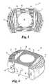
- FIG. 1is a top-view of a spinal spacer according to a first embodiment of the present invention.
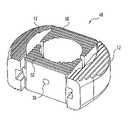
- FIG. 2is a perspective view of the spinal spacer of FIG. 1 .
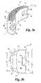
- FIG. 3 ais a perspective view of a lateral spacer.
- FIG. 3 bis an end view of the lateral spacer.
- FIG. 3 cis a top view of a donor bone.
- FIG. 3 dis a side view of a donor bone.
- FIG. 4is a top view of a connecting member according to FIG. 1 .
- FIG. 5is an end view of a lateral spacer according to a second embodiment of the present invention.
- FIG. 6is an end view of a connecting member according to the second embodiment of the present invention.
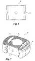
- FIG. 7is a perspective view of a spinal spacer according to a third embodiment of the present invention.
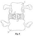
- FIG. 8is an end view of the lateral spacers inserted between vertebrae.
- FIG. 9is a cut-away top view of the lateral spacers of FIG. 8 .
- FIG. 10is an end view of the lateral spacers inserted between the vertebrae.
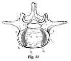
- FIG. 11is a cut-away top view of the lateral spacers of FIG. 10 .
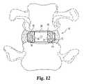
- FIG. 12is an end view of the spinal spacer inserted between the vertebrae.
- FIG. 13is a cut-away top view of the spinal spacer of FIG. 12 .
- FIG. 14is a side view of the inserted spinal spacer.
- the spinal spacer 10includes a pair of lateral spacers 12 and 13 , and a connecting member 28 engaged between the two lateral spacers.
- the connecting member 28makes the spinal spacer 10 a substantially rigid structure that inhibits movement of the lateral spacers once inserted between vertebrae.
- lateral spacers 12 and 13are substantially identical mirror images of each other.
- the following detailed description of lateral spacer 12applies equally to lateral spacer 13 .
- the lateral spacer 12has a medial side 14 adapted for coupling to the connecting member 28 .
- the lateral spacer 12has a lateral side 22 which is opposite from the medial side 14 .
- the term “lateral”refers to the lateral portion of the spine and the term “medial” refers to the medial portion of the spine.
- Spacer 12includes an upper vertebra engaging surface 24 and a lower vertebra engaging surface 25 .
- the upper and lower surfaces 24 and 25include ridges, such as shown in the figures, or other anti-migration structures defined on the surface to limit movement of the device in the disc space. It is contemplated that the grooves can be oriented and configured in a different manner in order to prevent migration in various directions.
- Beveled edges 26 and 27extend between the lateral side wall 22 and the upper and lower surfaces 24 and 25 , respectively. These beveled edges 26 which make insertion of the spinal spacer 10 easier between adjacent vertebrae. Further, these beveled edges 26 reduce the trauma to surrounding tissue that might be caused by a spacer that has sharp edges.
- the lateral side 22as shown in FIGS. 3 a - 3 b , has an arcuate shape in order to generally coincide with the relatively strong ring apophysis of the vertebral body (see B 3 of FIG. 9 ).
- the height of lateral spacer 12also approximates the natural geometry of the vertebral endplates. More specifically, the lateral most height H 1 of the spacer occurs at the maximum point of curvature 23 of the convex lateral side wall. From this point, the implant increases in height to the maximum height H 2 adjacent the juncture of medial side wall 14 and end wall 68 . In a preferred aspect of the invention, the transition in height between H 1 and H 2 is gradual and substantially continuous.
- the upper and lower surfaces 24 and 25curve in a non-linear fashion between the height H 1 on the lateral side to the height H 2 on the medial side to form a convex surface. [Is there a known radius of curvature?] Still further, for some applications it may be desirable to reduce the implant height from a maximum H 2 at anterior end 68 to a smaller height H 3 at posterior end 69 (see FIG. 14 ).
- the lateral spacer 12is coupled at its medial side 14 to the connecting member 28 . It is contemplated that the lateral spacer 12 can be coupled to the connecting member 28 by using a number of different coupling mechanisms including adhesives, screws, rail/channel connections, bioresorbable fasteners and other mechanisms used to connect components as known to those skilled in the relevant art.
- the lateral spacer 12according to the first embodiment of the present invention has a channel 18 that couples to rails 30 of the connecting member 28 .
- the channel 18as shown in FIG. 3 a , is formed on the medial side 14 of the lateral spacer 12 . In a preferred embodiment, channel 18 extends in substantially parallel alignment to longitudinal axis L 1 .
- Channel 18is defined by lower surface 62 , opposing upper surface 66 and intervening side surface 64 .
- the surfaces 62 , 64 and 66are interrupted by concave medial surface 14 and resume adjacent posterior end 69 .
- Preferable channel 18terminates in an angular end face 20 which acts as a stopper for the rails of the central spacer.
- the angular shape of end face 20improves the interconnection between the lateral spacer 12 and the rail 30 .
- the channel 18can have a dovetail cross-sectional profile in order to improve the interlock between the channel 18 and the rail 30 .
- the lateral spacers 12are made from bone. If the lateral spacers 12 are made from bone, the lateral spacers 12 can be slowly incorporated into the patient's body after implantation. This in turn will create a stronger fusion mass between the vertebrae. Furthermore, postoperative imaging is better when the lateral spacers 12 are made from bone, because bone does not cause scattering like with metallic implants in CT or MRI imaging.
- Lateral spacer 12may be manufactured using available forms of cortical autograft, allograft or xenograft bone. Multiple lateral spacers 12 may be made from a single bone or from different bones. The lateral spacer 12 may be fabricated from portions of long bone. Since bone for implants is a scarce commodity, it is desirable to use as much of the donor bone as possible. Thus, it is desirable to have the lateral spacer 12 made from remnants of bone. As shown in FIGS. 3 c - 3 d , the lateral spacer 12 may be obtained from remnants of donor bone utilized to form other types of spinal spacers, and from upper and lower end portions of the diaphysis of long bones lacking the required properties.
- a cylindrical bone graft 102may be cut from donor bone 100 .
- Cylindrical implant 102takes a portion of the medullary canal 106 but leaves a portion in remnant 104 .
- the remaining bone remnant 104while too small to be utilized as cylindrical implant, may be formed into an implant suitable for the present invention.
- a portion or the entire medial side 14 of the lateral spacer 12can be defined by a medullary canal 16 in order to provide a curved surface.
- a portion of the medial side 14 of the lateral spacer 12can contain a portion of the medullary canal 16 .
- Donor bonecan be used more efficiently when the medullary canal 16 is used to define a portion of the medial side. It will be understood that cleaning and preparation of the bone may slightly alter the naturally occurring medullary canal without deviating from the present invention.
- the connecting member 28includes rails 30 and 31 , opposing vertebrae engaging surfaces 32 (the identical bottom surface is not shown), central opening 34 , guide bore 36 , and beveled edges 38 .
- the rails 30 and 31are used to couple the connecting member 28 to the lateral spacers 12 and 13 .
- the connecting member 28includes at least one guide bore 36 . Medical instruments can be attached to the connecting member 28 at the guide bore 36 during implantation.
- the connecting member 28may be manufactured using available forms of autograft, allograft or xenograft donor bone.
- the donor bonecan include cortical bone, cancellous bone, and any combination thereof. After the donor bone is obtained, the bone then can be sculpted according to the size of the intervertebral space. Further, the connecting member 28 may include a medullary canal that naturally defines central opening 34 when the connecting member 28 is formed from bone. As shown in FIG. 4 , in a preferred aspect of the invention, donor bone otherwise unsuitable for implantation may be used to form a modular bone graft according to the present invention.
- a donor bone segment 200lacks sufficient diameter D 1 to provide good contact with the stronger bone of the vertebral endplate, particularly along the lateral edges adjacent the ring apophysis B 3 . While it may be possible to obtain bone having a sufficient diameter, bone resources are scarce thereby limiting the availability of such bone. Even if available, large sections of the anterior and posterior donor bone portions would be wasted in the machining process to achieve a properly dimensioned spacer.
- the medullary canalextends through the connecting member 28 , with openings at both vertebrae engaging surfaces 32 . During implantation, the central opening 34 can be filled with bone graft material in order to promote fusion of the vertebrae.
- the graft materialcan include cancellous bone, bone chips, or other suitable bone graft substitute material as known in the relevant art.
- Guide bore 36may be used to engage an insertion tool (not shown). Further, guide bore 36 may also be used as an injection port so that the graft material can be injected into the central opening 34 after implantation.
- At least the connecting member 28 or one of the lateral spacers 12is made from bone in order to promote the creation of a strong fusion mass between the vertebrae after implantation.
- all three components/elements 12 , 28 of the spinal spacerare made from bone (bone elements) and cooperate to form a modular bone graft adapted for interbody fusion.
- FIGS. 5-6A second embodiment of the present invention is shown in FIGS. 5-6 .
- a lateral spacer 40has a rail 42 and not a channel.
- a connecting member 44has a pair of channels 46 instead of a pair of rails. The lateral spacer 40 and the connecting member 44 then can be coupled together by the rails 42 and channels 46 .
- a third embodiment of the present inventionis shown in FIG. 7 .
- a spinal spacer 48 according to the third embodiment of the present inventionincludes a pair of the lateral spacers 12 , a first connecting member 50 , and a second connecting member 52 .
- the first and second connecting members 50 , 52are coupled to the lateral spacers 12 using the same connecting mechanisms as discussed above.
- Using the two smaller connecting members 50 , 52 instead of a single larger connecting member 28further reduces the required size of the original bone stock, thereby making more donor bone segments suitable for use in a modular bone graft for spinal fusion.
- single piece spinal spacersare not readily adapted for modern anterior fusion techniques.
- a 15-inch incisionwas made through the abdomen and a relatively large single piece fusion component was implanted through the incision.
- anterior fusionis accomplished through a much smaller 1.5-2 inch incision and does not require splitting of abdominal muscles.
- the surgeonwill make an incision of the above-mentioned size in order to permit visualization of approximately 45° of the disc annulus.
- Newer disc resection techniquesare readily adapted to incisions of this limited size. Since the spinal spacer 10 is not a unitary piece, its components 12 , 13 and 28 can be easily inserted through a relatively small incision and assembled between the vertebrae.
- the spinal spacer 10when assembled provides a large load-bearing surface which covers a significant portion of the vertebral body.
- the central portion of a vertebral bodycontains relatively weak cancellous bone, and the outer portion (apophyseal ring) of the vertebral body contains relatively strong and dense apophyseal bone.
- the lateral spacers 12are positioned over the relatively stronger apophyseal ring of the vertebral body. This configuration allows the vertebrae to be laterally supported at their strongest areas, and subsidence of the spacer 10 into the vertebrae is prevented.
- the assembled spinal spacer 10may be tapered in order to better match the intervertebral space.
- FIGS. 9 and 13A comparison between FIGS. 9 and 13 can illustrate one important feature of the present invention.
- the vertebral body Bis represented by its regions of bone strength.
- the central kidney-shaped portion B 1 of the vertebral body Bshown best in FIG. 11 , comprises mostly the weak cancellous bone.
- An annular kidney-shaped region B 2 around the central portioncontains stronger bone, while the ring apophysis B 3 has the strongest bone of the vertebral body.
- the present inventionstrives to load those regions of the vertebral body B that have the strongest load-bearing capability.
- the entire fusion device 10assumes a generally annular kidney-shape, corresponding to the annular kidney-shape of the stronger bone B 2 and B 3 in the vertebral body B.
- This overall shape of the device 10is achieved by the lateral spacers having each a partial lens shape, while the central spacer 28 has anterior and posterior portions configured to engage the stronger bone regions and the central opening 34 configured to be positioned adjacent weaker bone B 1 .
- the bone graft material placed in opening 34is generally positioned over the weakest portion B 1 of the vertebral body B.
- this portion B 1is also known to be highly vascular and biologically active, so that it is an excellent location for bone graft incorporation and fusion.
- FIGS. 8-14show how the spinal spacer 10 , according to a preferred aspect of the present invention, is implanted between adjacent vertebrae.
- the lateral spacers 12 and 13are inserted between the vertebrae from the anterior side.
- the disc materialis removed and the disc space prepared by known surgical techniques which will not be further discussed herein.
- Lateral spacers 12 and 13are then inserted through the opening 70 and into the disc space. During initial insertion, the lateral spacers are positioned near the center area of the vertebrae adjacent the much softer bone B 1 . Referring to FIGS.
- the lateral spacers 12 and 13are then outwardly moved (as shown by arrows A) in order to position the lateral spacers adjacent the lateral portions of the vertebra.
- lateral spacersabut bone regions B 2 and B 3 .
- central spacer 28is positioned adjacent opening 70 .
- Rails 30 and 31are aligned with corresponding grooves 18 and 19 , respectively, in the lateral spacers.
- the connecting member 12may be slidably advanced between the lateral spacer 12 to couple the lateral spacers 12 together.
- the assembled spinal spacer 10may be configured to match the natural contour of the spine.
- spinal spacer 10may as shown in FIG. 14 have a wedge-shaped profile or a tapered shape in order to better match the intervertebral space.
- the lateral spacers 12may also have a profile in which the cross-sectional area decreases from the medial side 14 to the lateral side 22 in order to better match the intervertebral space.
Landscapes
- Health & Medical Sciences (AREA)
- Engineering & Computer Science (AREA)
- Biomedical Technology (AREA)
- Orthopedic Medicine & Surgery (AREA)
- Vascular Medicine (AREA)
- Transplantation (AREA)
- Oral & Maxillofacial Surgery (AREA)
- Heart & Thoracic Surgery (AREA)
- Cardiology (AREA)
- Life Sciences & Earth Sciences (AREA)
- Animal Behavior & Ethology (AREA)
- General Health & Medical Sciences (AREA)
- Public Health (AREA)
- Veterinary Medicine (AREA)
- Neurology (AREA)
- Prostheses (AREA)
Abstract
Description
The present application is a continuation patent application of U.S. patent application Ser. No. 10/271,699, filed Oct. 16, 2002 now U.S. Pat. No. 6,896,701, which is a continuation of U.S. patent application Ser. No. 09/766,948, filed Jan. 22, 2001, now U.S. Pat. No. 6,468,311, which are hereby incorporated by reference in their entirety.
The present invention relates to implants for use in interbody fusion and methods of manufacturing such implants. More specifically, the present invention relates to implants formed from bone that are useful to restore height and promote bone fusion after a discectomy and methods for manufacturing such implants.
One of the leading causes of lower back pain and disability results from the rupture or degeneration of one or more lumbar discs in the spine. Pain and instability are caused by compression of spinal nerve roots by protruding damaged discs into the vertebral canal. Further, the damaged discs do not provide sufficient biomechanical support to allow a full range of vertebral motion. Normally intervertebral discs, which are located between end plates of adjacent vertebrae, stabilize the spine and distribute forces between the vertebrae and cushion vertebral bodies. These intervertebral discs include a semi-gelatinous component (nuclear pulpous), and a stiff fibrous ring (annulus fibrosis). The spinal discs may be displaced or damaged due to trauma, disease, or aging. A herniated or ruptured annulus fibrosis may result in nerve damage, pain, numbness, muscle weakness, and even paralysis. Furthermore, as a result of the normal aging process, discs may dehydrate and harden. This hardening of the disc reduces the disc space height which in turn produces instability of the spine and decreased mobility.
In the more severe cases, the disc tissue is irreparably damaged, and the entire disc has to be removed (discectomy). The discectomy is often followed by a fusion of adjacent vertebrae in order to stabilize the spine. In order to alleviate pain, abnormal joint mechanics, premature development of arthritis, and nerve damage, the disc space between the adjacent vertebrae may be maintained following the discectomy. Spacers or implants are used to maintain the intervertebral space between the adjacent vertebrae.
Current treatment methods utilize grafts of either bone or artificial implants to fill the intervertebral space between adjacent vertebrae. It is desirable that these implants not only fill the disc space vacated by the damaged disc, but also restore the disc space height to pre-damaged conditions. An implant must be sufficiently strong to bear substantially all of the body's weight above the intervertebral space. Furthermore, it is desirable to use the implants to promote fusion of adjacent vertebrae across the disc space and thereby promote mechanical stability. To be successful the implant must provide temporary structured support and allow bone growth to establish fusion between the adjacent vertebrae. Success of the discectomy and bony fusion typically requires the development of a contiguous growth of bone between adjacent vertebrae to create a solid mass of bone capable of withstanding the cyclic compressive spinal loads for the life of a patient.
Current methodologies use implants or grafts made of metal, plastic composites, ceramics, or bone. Natural bone grafts may be developed from autograft, allograft or xenograft. Other bone grafts may include certain man-made substances including binder joining bone chips, composite bone structures, ceramics minimizing bone, etc. The use of bone implants offers several advantages over the use of artificial spacers or implants. The bone implants have a suitable modulus of elasticity that is comparable to that of adjacent vertebrae. The bone implants can be provided with voids that can be packed with cancellous bone or other osteogenic material to promote bone growth and fusion between adjacent vertebrae. Implants formed by cortical bone have sufficient compressive strength to provide a biomechanically sound intervertebral spacer. Further, the implant bone will be replaced over time with the patient's own bone through the process of creeping substitution. In contrast to the bone implants, artificial implants do not fully incorporated into the fusion mass.
As more fully described in U.S. Pat. No. 5,397,364 to Kozak et al., incorporated by reference herein in its entirety, one principle in implant design is that the load transmitted between adjacent vertebrae should be on the strongest part of the vertebral body. This patent describes the desirability of concentrating the heaviest loads on or near the ring apophysis to avoid subsidence of the device into the surrounding vertebral end plates and subsequent collapse of the intradiscal space.
Another principle in implant design is that a spacer should be structured such that implantation of the spacer is minimally invasive. Relatively large single piece spacers capable of transmitting loads to the ring apophysis require large incisions in order to be implanted between vertebrae. Such incisions extending the full width of the disc space create potential problems. More specifically, blood vessels, nerves, ligaments, muscles and other tissue naturally occurring adjacent the effected disc space must be severed or retracted out of harms way. In some cases, such as blood vessels and nerves, the obstructing structure may not be moved without permanent damage to the patient. In these cases, large implants may not be used.
In addition to the damage done to the tissues surrounding the disc space and the extended healing time required to recover from the trauma, damage done to the ligaments extending between adjacent vertebrae may negatively impact the success of the operation. The severed or stretched ligaments may no longer function to maintain tension on the disc space thereby allowing the implant to migrate. Further, unexpected movement between the vertebra and the implant may prevent or impede bone fusion.
A further consideration is that a spacer fit the patient's intradiscal anatomy in order to restore the proper anatomic relationship between the disc, pedicle, nerve root, and facet joints. Restoration of normal disc height will also return the disc annulus to tension, reduce annular bulge and promote stability. At the same time, the device should not shield the spine from all of the stresses normally borne by the spine, since it has been found that reduction of normal stress on the vertebrae can result in bone loss. Also, a spacer should be able to be slowly incorporated into the patient's own body in order to create a stronger fusion mass between vertebrae.
The availability of suitable bone is another consideration when developing bone grafts for disc space insertion. As will be appreciated, only certain bones in the human body have sufficient cortical bone mass to support the loads commonly experienced in the spine. While the potential exists for greater availability of suitable bone sources from animals, at present, such sources are not commercially viable due, at least in part, to the potential for rejection by the human body. A further factor is the relatively few people who agree to donor their bodies for these uses. Thus, there is a need to develop superior implants for interbody fusion from the imperfect donor bone stock available.
With these goals in mind, the Applicants have developed a spinal spacer and method of manufacturing according to the present invention.
The present invention is directed to an interbody fusion device for engagement between vertebrae. The fusion device includes a pair of lateral spacers for spacing the vertebrae and a connecting member made of bone which is adapted to couple together the lateral spacers when the spacer is inserted between the vertebrae.
The present invention is also directed to a modular interbody fusion device that includes a first bone element, a second bone element, and a third bone element. The first, second, and third bone elements are adapted for coupling together when inserted between vertebrae.
In addition, the present invention is directed to a spinal spacer that includes a pair of lateral spacers made of bone and a connecting member which is adapted to couple the lateral spacers together when inserted between vertebrae. In a preferred embodiment, the lateral spacers include channels for receiving a portion of the connecting member.
The present invention is also directed to a method of manufacturing a spinal spacer. The method of manufacturing the spinal spacer includes obtaining a first piece of bone having a first medial side with a portion thereof defined by a first medullary canal portion. Further, the method includes obtaining a second piece of bone having a second medial side with a portion thereof defined by a second medullary canal portion, and obtaining a third piece of bone with a medullary canal defined therein. The method also includes forming a first structure in the first medial side of the first piece of bone, forming a second structure in the second medial side of the second piece of bone, and forming a third and fourth structure in the third piece of bone configured for engagement with the first and second structures, respectively.
In still another aspect of the present invention, a method for implanting bone grafts for spinal fusion is provided. The method includes positioning a first bone graft in a first lateral portion of the disc space and positioning a second bone graft in a second lateral portion of the disc space opposite said first lateral portion. The method further includes positioning a central spacer between said first and second bone grafts. Preferably, said spacer interconnects the first and second bone grafts. Still more preferably, the first and second bone grafts include grooves and the central spacer includes corresponding rails. In this embodiment, the inserting step also includes aligning the rails within the grooves before insertion.
Further objects, features, benefits, aspects, and advantages of the present invention shall become apparent from the detailed drawings and descriptions provided herein.
For the purposes of promoting an understanding of the principles of the present invention, reference will now be made to the embodiments illustrated in the drawings, and specific language will be used to describe the same. It will nevertheless be understood that no limitation of the scope of the invention is intended thereby. Any alterations and further modification in the described processes, systems, or devices, and any further applications of the principles of the invention as described herein are contemplated as would normally occur to one skilled in the art to which the invention relates. Preferred embodiments of the invention are shown in great detail, although it will be apparent to those skilled in the relevant art that some of the features may not be shown for the sake of clarity.
Referring now toFIGS. 1-2 , aspinal spacer 10 according to a first preferred embodiment of the present invention is shown. Thespinal spacer 10 includes a pair oflateral spacers member 28 engaged between the two lateral spacers. In a preferred aspect the connectingmember 28 makes the spinal spacer10 a substantially rigid structure that inhibits movement of the lateral spacers once inserted between vertebrae.
Referring toFIGS. 1-2 , it will be appreciated that in a preferredembodiment lateral spacers lateral spacer 12 applies equally tolateral spacer 13. As shown inFIGS. 3 a-3b, thelateral spacer 12 has amedial side 14 adapted for coupling to the connectingmember 28. Further, thelateral spacer 12 has alateral side 22 which is opposite from themedial side 14. The term “lateral” refers to the lateral portion of the spine and the term “medial” refers to the medial portion of the spine.Spacer 12 includes an uppervertebra engaging surface 24 and a lowervertebra engaging surface 25. Preferably, the upper andlower surfaces lateral side wall 22 and the upper andlower surfaces beveled edges 26 which make insertion of thespinal spacer 10 easier between adjacent vertebrae. Further, thesebeveled edges 26 reduce the trauma to surrounding tissue that might be caused by a spacer that has sharp edges. Thelateral side 22, as shown inFIGS. 3 a-3b, has an arcuate shape in order to generally coincide with the relatively strong ring apophysis of the vertebral body (see B3 ofFIG. 9 ).
In addition to the convexlateral wall 22 adapted to conform to the vertebral endplate geometry, in a preferred aspect, the height oflateral spacer 12 also approximates the natural geometry of the vertebral endplates. More specifically, the lateral most height H1of the spacer occurs at the maximum point ofcurvature 23 of the convex lateral side wall. From this point, the implant increases in height to the maximum height H2adjacent the juncture ofmedial side wall 14 andend wall 68. In a preferred aspect of the invention, the transition in height between H1and H2is gradual and substantially continuous. Still more preferably, the upper andlower surfaces anterior end 68 to a smaller height H3at posterior end69 (seeFIG. 14 ).
Now referring toFIG. 2 , thelateral spacer 12 is coupled at itsmedial side 14 to the connectingmember 28. It is contemplated that thelateral spacer 12 can be coupled to the connectingmember 28 by using a number of different coupling mechanisms including adhesives, screws, rail/channel connections, bioresorbable fasteners and other mechanisms used to connect components as known to those skilled in the relevant art. As shown inFIG. 2 , thelateral spacer 12 according to the first embodiment of the present invention has achannel 18 that couples torails 30 of the connectingmember 28. Thechannel 18, as shown inFIG. 3 a, is formed on themedial side 14 of thelateral spacer 12. In a preferred embodiment,channel 18 extends in substantially parallel alignment to longitudinal axis L1. Channel18 is defined bylower surface 62, opposing upper surface66 and interveningside surface 64. Thesurfaces medial surface 14 and resume adjacentposterior end 69.Preferable channel 18 terminates in anangular end face 20 which acts as a stopper for the rails of the central spacer. The angular shape ofend face 20 improves the interconnection between thelateral spacer 12 and therail 30. If desired, thechannel 18 can have a dovetail cross-sectional profile in order to improve the interlock between thechannel 18 and therail 30.
According to a preferred form of the present invention, thelateral spacers 12 are made from bone. If thelateral spacers 12 are made from bone, thelateral spacers 12 can be slowly incorporated into the patient's body after implantation. This in turn will create a stronger fusion mass between the vertebrae. Furthermore, postoperative imaging is better when thelateral spacers 12 are made from bone, because bone does not cause scattering like with metallic implants in CT or MRI imaging.
In a preferred embodiment, a portion or the entiremedial side 14 of thelateral spacer 12 can be defined by amedullary canal 16 in order to provide a curved surface. As shown inFIG. 3 , a portion of themedial side 14 of thelateral spacer 12 can contain a portion of themedullary canal 16. Donor bone can be used more efficiently when themedullary canal 16 is used to define a portion of the medial side. It will be understood that cleaning and preparation of the bone may slightly alter the naturally occurring medullary canal without deviating from the present invention.
Referring now toFIGS. 1-2 , a perspective view of thespinal spacer 10 according to the first embodiment of the present invention is shown. As shown inFIGS. 2 and 4 c, the connectingmember 28 includesrails central opening 34, guide bore36, and beveled edges38. As discussed above, a number of different coupling mechanisms can be used to couple thelateral spacers 12 to the connectingmember 28. In the preferred form therails member 28 to thelateral spacers member 28 is implanted, thevertebrae engaging surfaces 32 contact corresponding adjacent vertebrae. In addition, thesevertebrae engaging surfaces 32 may be grooved in order to reduce migration or expulsion of the insertedspinal spacer 10. In a preferred form, the connectingmember 28 includes at least one guide bore36. Medical instruments can be attached to the connectingmember 28 at the guide bore36 during implantation.
In a preferred form, the connectingmember 28 may be manufactured using available forms of autograft, allograft or xenograft donor bone. The donor bone can include cortical bone, cancellous bone, and any combination thereof. After the donor bone is obtained, the bone then can be sculpted according to the size of the intervertebral space. Further, the connectingmember 28 may include a medullary canal that naturally definescentral opening 34 when the connectingmember 28 is formed from bone. As shown inFIG. 4 , in a preferred aspect of the invention, donor bone otherwise unsuitable for implantation may be used to form a modular bone graft according to the present invention. More specifically, and by way of example only, a donor bone segment200 lacks sufficient diameter D1to provide good contact with the stronger bone of the vertebral endplate, particularly along the lateral edges adjacent the ring apophysis B3. While it may be possible to obtain bone having a sufficient diameter, bone resources are scarce thereby limiting the availability of such bone. Even if available, large sections of the anterior and posterior donor bone portions would be wasted in the machining process to achieve a properly dimensioned spacer. In the preferred embodiment ofFIG. 4 , the medullary canal extends through the connectingmember 28, with openings at both vertebrae engaging surfaces32. During implantation, thecentral opening 34 can be filled with bone graft material in order to promote fusion of the vertebrae. The graft material can include cancellous bone, bone chips, or other suitable bone graft substitute material as known in the relevant art. Guide bore36 may be used to engage an insertion tool (not shown). Further, guide bore36 may also be used as an injection port so that the graft material can be injected into thecentral opening 34 after implantation.
Inspinal spacer 10 according to the present invention, at least the connectingmember 28 or one of thelateral spacers 12 is made from bone in order to promote the creation of a strong fusion mass between the vertebrae after implantation. In a preferred form all three components/elements
A second embodiment of the present invention is shown inFIGS. 5-6 . As shown inFIG. 5 , alateral spacer 40 has arail 42 and not a channel. Accordingly, as shown inFIG. 6 , a connectingmember 44 has a pair ofchannels 46 instead of a pair of rails. Thelateral spacer 40 and the connectingmember 44 then can be coupled together by therails 42 andchannels 46.
A third embodiment of the present invention is shown inFIG. 7 . Aspinal spacer 48 according to the third embodiment of the present invention includes a pair of thelateral spacers 12, a first connectingmember 50, and a second connectingmember 52. The first and second connectingmembers lateral spacers 12 using the same connecting mechanisms as discussed above. Using the two smaller connectingmembers member 28 further reduces the required size of the original bone stock, thereby making more donor bone segments suitable for use in a modular bone graft for spinal fusion.
As explained more fully in U.S. Pat. No. 5,397,364 to Kozak et al., incorporated herein by reference, single piece spinal spacers are not readily adapted for modern anterior fusion techniques. In the early history of anterior fusion, a 15-inch incision was made through the abdomen and a relatively large single piece fusion component was implanted through the incision. More recently, anterior fusion is accomplished through a much smaller 1.5-2 inch incision and does not require splitting of abdominal muscles. In a typical procedure, the surgeon will make an incision of the above-mentioned size in order to permit visualization of approximately 45° of the disc annulus. Newer disc resection techniques are readily adapted to incisions of this limited size. Since thespinal spacer 10 is not a unitary piece, itscomponents
Furthermore, thespinal spacer 10 when assembled provides a large load-bearing surface which covers a significant portion of the vertebral body. The central portion of a vertebral body contains relatively weak cancellous bone, and the outer portion (apophyseal ring) of the vertebral body contains relatively strong and dense apophyseal bone. When thespinal spacer 10 is assembled, thelateral spacers 12 are positioned over the relatively stronger apophyseal ring of the vertebral body. This configuration allows the vertebrae to be laterally supported at their strongest areas, and subsidence of thespacer 10 into the vertebrae is prevented. Further, the assembledspinal spacer 10 may be tapered in order to better match the intervertebral space.
A comparison betweenFIGS. 9 and 13 can illustrate one important feature of the present invention. InFIG. 9 , the vertebral body B is represented by its regions of bone strength. The central kidney-shaped portion B1of the vertebral body B, shown best inFIG. 11 , comprises mostly the weak cancellous bone. An annular kidney-shaped region B2around the central portion contains stronger bone, while the ring apophysis B3has the strongest bone of the vertebral body. With this in mind, the present invention strives to load those regions of the vertebral body B that have the strongest load-bearing capability. For example, theentire fusion device 10 assumes a generally annular kidney-shape, corresponding to the annular kidney-shape of the stronger bone B2and B3in the vertebral body B. This overall shape of thedevice 10 is achieved by the lateral spacers having each a partial lens shape, while thecentral spacer 28 has anterior and posterior portions configured to engage the stronger bone regions and thecentral opening 34 configured to be positioned adjacent weaker bone B1. The bone graft material placed in opening34 is generally positioned over the weakest portion B1of the vertebral body B. However, this portion B1is also known to be highly vascular and biologically active, so that it is an excellent location for bone graft incorporation and fusion.
Referring toFIG. 12 ,central spacer 28 is positionedadjacent opening 70.Rails corresponding grooves member 12 may be slidably advanced between thelateral spacer 12 to couple thelateral spacers 12 together.
As shown inFIG. 14 , the assembledspinal spacer 10 may be configured to match the natural contour of the spine. By way of example,spinal spacer 10 may as shown inFIG. 14 have a wedge-shaped profile or a tapered shape in order to better match the intervertebral space. Further, thelateral spacers 12, according to the present invention, may also have a profile in which the cross-sectional area decreases from themedial side 14 to thelateral side 22 in order to better match the intervertebral space.
While specific embodiments of the invention have been shown and described in detail, the breadth and scope of the present invention should not be limited by the above described exemplary embodiments, but should be defined only in accordance with the following claims and their equivalents. It is understood that only the preferred embodiments have been shown and described and that all changes and modifications that come within the spirit of the invention are desired to be protected.
Claims (15)
1. A spinal implant for engagement between vertebrae, comprising:
at least two lateral spacers made of bone remnants, said lateral spacers each having opposite upper and lower vertebral engaging surfaces adapted to engage the vertebrae and opposite lateral and medial sides, said upper and lower vertebral engaging surfaces each including anti-migration structures comprising a plurality of ridges and grooves configured to limit movement of said lateral spacers in a disc space between the vertebrae, and wherein said medial sides each include a concave recess at least partially defined by at least a portion of a medullary canal wall, said concave recess extending from said upper vertebral engaging surface to said lower vertebral engaging surface and defining a medially-facing concave surface; and
a separate connecting member connected to said medial sides to provide a multi-piece implant assembly, said connecting member including a portion positioned within an interior space between said medially-facing concave surfaces of said lateral spacers, said portion having upper and lower vertebral engaging surfaces and defining a central opening extending therethrough and opening onto each of said upper and lower vertebral engaging surfaces;
a first coupling mechanism defined between said connecting member and a first of said lateral spacers, said first coupling mechanism comprising a first projecting portion engaged within a first recess;
a second coupling mechanism defined between said connecting member and a second of said lateral spacers, said second coupling mechanism comprising a second projecting portion engaged within a second recess; and
wherein said first and second coupling mechanisms interconnect said connecting member with said first and second lateral spacers to provide said multi-piece implant assembly.
2. The implant ofclaim 1 , wherein said lateral side of each of said lateral spacers includes a laterally-facing convex surface, said laterally-facing convex surface extending along substantially an entire length of said lateral side of said lateral spacers.
3. The implant ofclaim 1 , wherein said first and second lateral spacers each have opposite anterior and posterior end portions with said lateral and medial sides extending along a longitudinal axis between said anterior and posterior end portions; and
wherein said medially-facing concave surface extends axially along a central portion of said medial side from said anterior end portion to said posterior end portion.
4. A spinal implant for engagement between vertebrae, comprising:
at least two lateral spacers made of bone remnants, said lateral spacers each having opposite upper and lower vertebral engaging surfaces adapted to engage the vertebrae and opposite lateral and medial sides, said upper and lower vertebral engaging surfaces each including anti-migration structures comprising a plurality of ridges and grooves configured to limit movement of said lateral spacers in a disc space between the vertebrae, and wherein said medial sides each include a concave recess at least partially defined by at least a portion of a medullary canal wall, said concave recess extending from said upper vertebral engaging surface to said lower vertebral engaging surface and defining a medially-facing concave surface; and
a separate connecting member connected to said lateral spacers at said medial sides to provide a multi-piece implant assembly, said connecting member including a portion positioned within an interior space between said medially-facing concave surfaces of said lateral spacers, said portion having upper and lower vertebral engaging surfaces and defining a central opening extending therethrough and opening onto each of said upper and lower vertebral engaging surfaces; and
wherein said connecting member has a pair of rails, and wherein each of said medial sides of said lateral spacers has a channel defined therein to receive said rails to interconnect said connecting member with said lateral spacers.
5. A spinal implant for engagement between vertebrae, comprising:
at least two lateral spacers made of bone remnants, said lateral spacers each having opposite upper and lower vertebral engaging surfaces adapted to engage the vertebrae and opposite lateral and medial sides, wherein said medial sides each include a concave recess at least partially defined by at least a portion of a medullary canal wall, said concave recess extending from said upper vertebral engaging surface to said lower vertebral engaging surface and defining a medially-facing concave surface; and
a separate connecting member connected to said lateral spacers at said medial sides to provide a multi-piece implant assembly, said connecting member including a portion positioned within an interior space between said medially-facing concave surfaces of said lateral spacers, said portion having upper and lower vertebral engaging surfaces and defining a central opening extending therethrough and opening onto each of said upper and lower vertebral engaging surfaces; and
wherein said connecting member has a pair of rails, and wherein each of said medial sides of said lateral spacers has a channel defined therein to receive said rails to interconnect said connecting member with said lateral spacers;
said lateral spacers each having a posterior end and an anterior end;
said anterior end defines an anterior end wall; and
said channel is interrupted by said concave recess and resumes adjacent said posterior end.
6. A spinal implant for engagement between vertebrae, comprising:
at least two lateral spacers formed from bone pieces that each include a portion of a medullary canal, each of said lateral spacers having:
opposite upper and lower vertebral engaging surfaces extending along a longitudinal axis and adapted to engage the vertebrae, said upper and lower vertebral engaging surfaces each including anti-migration structures comprising a plurality of ridges and grooves configured to limit movement of said lateral spacers in a disc space between the vertebrae,
opposite anterior and posterior end portions, and
opposite lateral and medial sides extending along said longitudinal axis, said medial side including a concave recess at least partially defined by said portion of the medullary canal, said concave recess defining a medially-facing concave surface extending along said longitudinal axis between said anterior and posterior end portions and between said upper and lower vertebral engaging surfaces; and
a separate connecting member extending between said medial sides of said lateral spacers and interconnected with said lateral spacers to provide a multi-piece implant assembly, said connecting member including anterior and posterior portions positioned between said anterior and posterior end portions of said lateral spacers and a central portion positioned within an interior space between said medially-facing concave surfaces of said lateral spacers; and
wherein said medial side of each of said lateral spacers defines a channel extending along said longitudinal axis, said connecting member including a pair of opposite rails engaged within said channels defined by said lateral spacers to provide said multi-piece implant assembly.
7. A spinal implant for engagement between vertebrae, comprising:
at least two lateral spacers formed of bone having a medullary canal, a first of said lateral spacers formed from a first bone piece segment including a medullary canal portion, a second of said lateral spacers formed from a second bone piece segment including a medullary canal portion, each of said lateral spacers including:
opposite upper and lower vertebral engaging surfaces extending along a longitudinal axis and adapted to engage the vertebrae,
opposite anterior and posterior end portions, and
opposite lateral and medial sides extending along said longitudinal axis, said lateral side including a laterally-facing convex surface extending along the longitudinal axis, said medial side including a concave recess at least partially defined by said medullary canal portion, said concave recess defining a medially-facing concave surface extending along said longitudinal axis between said anterior and posterior end portions and between said upper and lower vertebral engaging surfaces; and
a separate connecting member formed from a third bone piece segment, said connecting member extending between said medial sides of said lateral spacers and interconnected with said lateral spacers to provide a multi-piece implant assembly, said connecting member including anterior and posterior portions positioned between said anterior and posterior end portions of said lateral spacers and a central portion positioned within an interior space between said medially-facing concave surfaces of said lateral spacers; and
wherein said medial side of each of said lateral spacers defines a channel extending along said longitudinal axis, said connecting member including a pair of opposite rails engaged within said channels defined by said lateral spacers to provide said multi-piece implant assembly; and
wherein said channel is interrupted by said medially-facing concave surface.
8. A spinal implant for engagement between vertebrae, comprising:
at least two lateral spacers made of bone remnants, said lateral spacers each having opposite upper and lower vertebral engaging surfaces adapted to engage the vertebrae and opposite lateral and medial sides, said upper and lower vertebral engaging surfaces each including anti-migration structures comprising a plurality of ridges and grooves configured to limit movement of said lateral spacers in a disc space between the vertebrae, and wherein said medial sides each include a concave recess at least partially defined by at least a portion of a medullary canal wall, said concave recess extending from said upper vertebral engaging surface to said lower vertebral engaging surface and defining a medially-facing concave surface; and
a separate connecting member connected to said medial sides to provide a multi-piece implant assembly, said connecting member including a portion positioned within an interior space between said medially-facing concave surfaces of said lateral spacers, said portion having upper and lower vertebral engaging surfaces and defining a central opening extending therethrough and opening onto each of said upper and lower vertebral engaging surfaces;
a first coupling mechanism defined between said connecting member and a first of said lateral spacers, said first coupling mechanism comprising a first projecting portion engaged within a first recess;
a second coupling mechanism defined between said connecting member and a second of said lateral spacers, said second coupling mechanism comprising a second projecting portion engaged within a second recess; and
wherein said first and second projecting portions each comprise a rail and wherein said first and second recesses each comprise a channel, said rails engaged within said channels to interconnect said connecting member with said first and second lateral spacers to provide said multi-piece implant assembly.
9. The implant ofclaim 8 , wherein said first and second rails are defined by said connecting member and wherein said first and second channels are defined along said medial sides of said first and second lateral spacers, respectively.
10. A spinal implant for engagement between vertebrae, comprising:
at least two lateral spacers formed from bone pieces that each include a portion of a medullary canal, each of said lateral spacers having:
opposite upper and lower vertebral engaging surfaces extending along a longitudinal axis and adapted to engage the vertebrae, said upper and lower vertebral engaging surfaces each including anti-migration structures comprising a plurality of ridges and grooves configured to limit movement of said lateral spacers in a disc space between the vertebrae,
opposite anterior and posterior end portions, and
opposite lateral and medial sides extending along said longitudinal axis, said medial side including a concave recess at least partially defined by said portion of the medullary canal, said concave recess defining a medially-facing concave surface extending axially along a central portion of said medial side from said anterior end portion to said posterior end portion and between said upper and lower vertebral engaging surfaces; and
a separate connecting member extending between said medial sides of said lateral spacers and interconnected with said lateral spacers to provide a multi-piece implant assembly, said connecting member including anterior and posterior portions positioned between said anterior and posterior end portions of said lateral spacers and a central portion positioned within an interior space between said medially-facing concave surfaces defined by said central portions of said lateral spacers; and
a first coupling mechanism defined between said connecting member and a first of said lateral spacers, said first coupling mechanism comprising a first projecting portion engaged within a first recess;
a second coupling mechanism defined between said connecting member and a second of said lateral spacers, said second coupling mechanism comprising a second projecting portion engaged within a second recess; and
wherein said first and second coupling mechanisms interconnect said connecting member with said first and second lateral spacers to provide said multi-piece implant assembly, and wherein said first and second projecting portions each comprise a rail and wherein said first and second recesses each comprise a channel, said rails engaged within said channels to interconnect said connecting member with said first and second lateral spacers to provide said multi-piece implant assembly.
11. The implant ofclaim 10 , wherein said lateral side of each of said lateral spacers defines a laterally-facing convex surface extending along the longitudinal axis and shaped to correspond to an apophysis ring of the vertebrae, said laterally-facing convex surface extending along substantially an entire length of said lateral side of said lateral spacers.
12. The implant ofclaim 10 , wherein said connecting member includes upper and lower vertebral engaging surfaces and defines a central opening extending through said central portion and opening onto each of said upper and lower vertebral engaging surfaces, said upper and lower vertebral engaging surfaces of said connecting member each including anti-migration structures comprising a plurality of ridges and grooves configured to limit movement of said connecting member in a disc space between the vertebrae; and
further comprising an osteogenic material positioned within said central opening to facilitate fusion between the vertebrae.
13. A spinal implant for engagement between vertebrae, comprising:
at least two lateral spacers formed of bone having a medullary canal, a first of said lateral spacers formed from a first bone piece segment including a medullary canal portion, a second of said lateral spacers formed from a second bone piece segment including a medullary canal portion, each of said lateral spacers including:
opposite upper and lower vertebral engaging surfaces extending along a longitudinal axis and adapted to engage the vertebrae, said upper and lower vertebral engaging surfaces each including anti-migration structures comprising a plurality of ridges and grooves configured to limit movement of said lateral spacers in a disc space between the vertebrae,
opposite anterior and posterior end portions, and
opposite lateral and medial sides extending along said longitudinal axis, said lateral side including a laterally-facing convex surface extending along the longitudinal axis, said medial side including a concave recess at least partially defined by said medullary canal portion, said concave recess defining a medially-facing concave surface extending axially along a central portion of said medial side from said anterior end portion to said posterior end portion and between said upper and lower vertebral engaging surfaces; and
a separate connecting member formed from a third bone piece segment, said connecting member extending between said medial sides of said lateral spacers and interconnected with said lateral spacers to provide a multi-piece implant assembly, said connecting member including anterior and posterior portions positioned between said anterior and posterior end portions of said lateral spacers and a central portion positioned within an interior space between said medially-facing concave surfaces defined by said central portions of said lateral spacers;
a first coupling mechanism defined between said connecting member and a first of said lateral spacers, said first coupling mechanism comprising a first projecting portion engaged within a first recess;
a second coupling mechanism defined between said connecting member and a second of said lateral spacers, said second coupling mechanism comprising a second projecting portion engaged within a second recess; and
wherein said first and second coupling mechanisms interconnect said connecting member with said first and second lateral spacers to provide said multi-piece implant assembly, and wherein said first and second projecting portions each comprise a rail and wherein said first and second recesses each comprise a channel, said rails engaged within said channels to interconnect said connecting member with said first and second lateral spacers to provide said multi-piece implant assembly.
14. The implant ofclaim 13 , wherein said laterally-facing convex surface of each of said lateral spacers is shaped to correspond to an apophysis ring of the vertebrae, said laterally-facing convex surface extending along substantially an entire length of said lateral side of said lateral spacers.
15. The implant ofclaim 13 , wherein said connecting member includes upper and lower vertebral engaging surfaces and defines a central opening extending through said central portion and opening onto each of said upper and lower vertebral engaging surfaces, said central opening at least partially defined by a medullary canal of said third bone piece segment, said upper and lower vertebral engaging surfaces of said connecting member each including anti-migration structures comprising a plurality of ridges and grooves configured to limit movement of said connecting member in a disc space between the vertebrae.
Priority Applications (1)
| Application Number | Priority Date | Filing Date | Title |
|---|---|---|---|
| US11/072,466US7621960B2 (en) | 2001-01-22 | 2005-03-04 | Modular interbody fusion implant |
Applications Claiming Priority (3)
| Application Number | Priority Date | Filing Date | Title |
|---|---|---|---|
| US09/766,948US6468311B2 (en) | 2001-01-22 | 2001-01-22 | Modular interbody fusion implant |
| US10/271,699US6896701B2 (en) | 2001-01-22 | 2002-10-16 | Modular interbody fusion implant |
| US11/072,466US7621960B2 (en) | 2001-01-22 | 2005-03-04 | Modular interbody fusion implant |
Related Parent Applications (1)
| Application Number | Title | Priority Date | Filing Date |
|---|---|---|---|
| US10/271,699ContinuationUS6896701B2 (en) | 2001-01-22 | 2002-10-16 | Modular interbody fusion implant |
Publications (2)
| Publication Number | Publication Date |
|---|---|
| US20050149195A1 US20050149195A1 (en) | 2005-07-07 |
| US7621960B2true US7621960B2 (en) | 2009-11-24 |
Family
ID=25078015
Family Applications (3)
| Application Number | Title | Priority Date | Filing Date |
|---|---|---|---|
| US09/766,948Expired - Fee RelatedUS6468311B2 (en) | 2001-01-22 | 2001-01-22 | Modular interbody fusion implant |
| US10/271,699Expired - Fee RelatedUS6896701B2 (en) | 2001-01-22 | 2002-10-16 | Modular interbody fusion implant |
| US11/072,466Expired - Fee RelatedUS7621960B2 (en) | 2001-01-22 | 2005-03-04 | Modular interbody fusion implant |
Family Applications Before (2)
| Application Number | Title | Priority Date | Filing Date |
|---|---|---|---|
| US09/766,948Expired - Fee RelatedUS6468311B2 (en) | 2001-01-22 | 2001-01-22 | Modular interbody fusion implant |
| US10/271,699Expired - Fee RelatedUS6896701B2 (en) | 2001-01-22 | 2002-10-16 | Modular interbody fusion implant |
Country Status (8)
| Country | Link |
|---|---|
| US (3) | US6468311B2 (en) |
| EP (1) | EP1363566B1 (en) |
| JP (1) | JP2004522533A (en) |
| AT (1) | ATE444038T1 (en) |
| AU (1) | AU2002251773B2 (en) |
| CA (1) | CA2435832A1 (en) |
| DE (1) | DE60233861D1 (en) |
| WO (1) | WO2002065956A1 (en) |
Cited By (83)
| Publication number | Priority date | Publication date | Assignee | Title |
|---|---|---|---|---|
| USD623747S1 (en)* | 2009-06-30 | 2010-09-14 | Horton Kenneth L | Spinal implant |
| USD631967S1 (en)* | 2009-06-05 | 2011-02-01 | Horton Kenneth L | Spinal implant |
| US7914582B2 (en) | 2000-08-28 | 2011-03-29 | Vertebral Technologies, Inc. | Method and system for mammalian joint resurfacing |
| US7985258B2 (en)* | 1995-03-27 | 2011-07-26 | Warsaw Orthopedic Inc. | Methods and instruments for interbody fusion |
| US8038718B2 (en) | 2005-03-09 | 2011-10-18 | Vertebral Technologies, Inc. | Multi-composite disc prosthesis |
| US20120296433A1 (en)* | 2010-02-02 | 2012-11-22 | Azadeh Farin | Spine surgery device |
| US20130110247A1 (en)* | 2011-11-01 | 2013-05-02 | Amedica Corporation | Implants with a Connectable Insert and Related Systems and Methods |
| US8628578B2 (en) | 2011-12-19 | 2014-01-14 | Warsaw Orthopedic, Inc. | Expandable interbody implant and methods of use |
| US8641763B2 (en) | 2011-07-14 | 2014-02-04 | James J. Yue | Spinal fusion devices and a method of performing spinal fusion |
| US8685095B2 (en) | 2011-04-19 | 2014-04-01 | Warsaw Orthopedic, Inc. | Expandable implant system and methods of use |
| US8740983B1 (en) | 2009-11-11 | 2014-06-03 | Nuvasive, Inc. | Spinal fusion implants and related methods |
| US8840668B1 (en) | 2009-11-11 | 2014-09-23 | Nuvasive, Inc. | Spinal implants, instruments and related methods |
| US9034045B2 (en) | 2013-03-15 | 2015-05-19 | Globus Medical, Inc | Expandable intervertebral implant |
| US9149367B2 (en) | 2013-03-15 | 2015-10-06 | Globus Medical Inc | Expandable intervertebral implant |
| US9186258B2 (en) | 2013-03-15 | 2015-11-17 | Globus Medical, Inc. | Expandable intervertebral implant |
| US9198765B1 (en) | 2011-10-31 | 2015-12-01 | Nuvasive, Inc. | Expandable spinal fusion implants and related methods |
| US9204972B2 (en) | 2013-03-01 | 2015-12-08 | Globus Medical, Inc. | Articulating expandable intervertebral implant |
| USD745159S1 (en) | 2013-10-10 | 2015-12-08 | Nuvasive, Inc. | Intervertebral implant |
| US9216096B2 (en) | 2010-03-16 | 2015-12-22 | Pinnacle Spine Group, Llc | Intervertebral implants and related tools |
| US9220604B2 (en) | 2010-12-21 | 2015-12-29 | DePuy Synthes Products, Inc. | Intervertebral implants, systems, and methods of use |
| US9238319B2 (en) | 2013-03-14 | 2016-01-19 | DePuy Synthes Products, Inc. | Hybrid intervertebral disc spacer device and method of manufacturing the same |
| US9241809B2 (en) | 2010-12-21 | 2016-01-26 | DePuy Synthes Products, Inc. | Intervertebral implants, systems, and methods of use |
| US9295562B2 (en) | 2008-01-17 | 2016-03-29 | DePuy Synthes Products, Inc. | Expandable intervertebral implant and associated method of manufacturing the same |
| US9320615B2 (en) | 2010-06-29 | 2016-04-26 | DePuy Synthes Products, Inc. | Distractible intervertebral implant |
| US9351848B2 (en) | 2010-09-03 | 2016-05-31 | Globus Medical, Inc. | Expandable fusion device and method of installation thereof |
| US9358122B2 (en) | 2011-01-07 | 2016-06-07 | K2M, Inc. | Interbody spacer |
| US9380932B1 (en) | 2011-11-02 | 2016-07-05 | Pinnacle Spine Group, Llc | Retractor devices for minimally invasive access to the spine |
| US9402738B2 (en) | 2013-02-14 | 2016-08-02 | Globus Medical, Inc. | Devices and methods for correcting vertebral misalignment |
| US9402735B2 (en) | 2008-11-07 | 2016-08-02 | DePuy Synthes Products, Inc. | Zero-profile interbody spacer and coupled plate assembly |
| US9402739B2 (en) | 2014-02-07 | 2016-08-02 | Globus Medical, Inc. | Variable lordosis spacer and related methods of use |
| US9402737B2 (en) | 2007-06-26 | 2016-08-02 | DePuy Synthes Products, Inc. | Highly lordosed fusion cage |
| US9414934B2 (en) | 2008-04-05 | 2016-08-16 | DePuy Synthes Products, Inc. | Expandable intervertebral implant |
| US9445919B2 (en) | 2011-12-19 | 2016-09-20 | Warsaw Orthopedic, Inc. | Expandable interbody implant and methods of use |
| US9463097B2 (en) | 2003-02-06 | 2016-10-11 | DePuy Synthes Products, Inc. | Intervertebral implant |
| US9510953B2 (en) | 2012-03-16 | 2016-12-06 | Vertebral Technologies, Inc. | Modular segmented disc nucleus implant |
| US9526620B2 (en) | 2009-03-30 | 2016-12-27 | DePuy Synthes Products, Inc. | Zero profile spinal fusion cage |
| US9561117B2 (en) | 2012-07-26 | 2017-02-07 | DePuy Synthes Products, Inc. | Expandable implant |
| US9566169B2 (en) | 2014-03-13 | 2017-02-14 | DePuy Synthes Products, Inc. | ACIS allograft designs |
| US9566168B2 (en) | 2010-09-03 | 2017-02-14 | Globus Medical, Inc. | Expandable fusion device and method of installation thereof |
| US9572681B2 (en) | 2002-02-19 | 2017-02-21 | DePuy Synthes Products, Inc. | Intervertebral implant |
| US9585765B2 (en) | 2013-02-14 | 2017-03-07 | Globus Medical, Inc | Devices and methods for correcting vertebral misalignment |
| US9717601B2 (en) | 2013-02-28 | 2017-08-01 | DePuy Synthes Products, Inc. | Expandable intervertebral implant, system, kit and method |
| US9724207B2 (en) | 2003-02-14 | 2017-08-08 | DePuy Synthes Products, Inc. | In-situ formed intervertebral fusion device and method |
| US9737414B2 (en) | 2006-11-21 | 2017-08-22 | Vertebral Technologies, Inc. | Methods and apparatus for minimally invasive modular interbody fusion devices |
| US9744049B2 (en) | 2007-11-16 | 2017-08-29 | DePuy Synthes Products, Inc. | Low profile intervertebral implant |
| US9750552B2 (en) | 2009-07-06 | 2017-09-05 | DePuy Synthes Products, Inc. | Expandable fixation assemblies |
| US9782265B2 (en) | 2013-02-15 | 2017-10-10 | Globus Medical, Inc | Articulating and expandable vertebral implant |
| US9833334B2 (en) | 2010-06-24 | 2017-12-05 | DePuy Synthes Products, Inc. | Enhanced cage insertion assembly |
| US9848994B2 (en)* | 2011-09-16 | 2017-12-26 | Globus Medical, Inc. | Low profile plate |
| US9867718B2 (en) | 2014-10-22 | 2018-01-16 | DePuy Synthes Products, Inc. | Intervertebral implants, systems, and methods of use |
| US9913727B2 (en) | 2015-07-02 | 2018-03-13 | Medos International Sarl | Expandable implant |
| US9949769B2 (en) | 2004-03-06 | 2018-04-24 | DePuy Synthes Products, Inc. | Dynamized interspinal implant |
| US9993349B2 (en) | 2002-06-27 | 2018-06-12 | DePuy Synthes Products, Inc. | Intervertebral disc |
| US10070970B2 (en) | 2013-03-14 | 2018-09-11 | Pinnacle Spine Group, Llc | Interbody implants and graft delivery systems |
| US10105239B2 (en) | 2013-02-14 | 2018-10-23 | Globus Medical, Inc. | Devices and methods for correcting vertebral misalignment |
| US10117754B2 (en) | 2013-02-25 | 2018-11-06 | Globus Medical, Inc. | Expandable intervertebral implant |
| US10159582B2 (en) | 2011-09-16 | 2018-12-25 | DePuy Synthes Products, Inc. | Removable, bone-securing cover plate for intervertebral fusion cage |
| US10369015B2 (en) | 2010-09-23 | 2019-08-06 | DePuy Synthes Products, Inc. | Implant inserter having a laterally-extending dovetail engagement feature |
| US10390963B2 (en) | 2006-12-07 | 2019-08-27 | DePuy Synthes Products, Inc. | Intervertebral implant |
| USD858769S1 (en) | 2014-11-20 | 2019-09-03 | Nuvasive, Inc. | Intervertebral implant |
| US10398563B2 (en) | 2017-05-08 | 2019-09-03 | Medos International Sarl | Expandable cage |
| US10433974B2 (en) | 2003-06-30 | 2019-10-08 | DePuy Synthes Products, Inc. | Intervertebral implant with conformable endplate |
| US10478313B1 (en) | 2014-01-10 | 2019-11-19 | Nuvasive, Inc. | Spinal fusion implant and related methods |
| US10500062B2 (en) | 2009-12-10 | 2019-12-10 | DePuy Synthes Products, Inc. | Bellows-like expandable interbody fusion cage |
| US10512548B2 (en) | 2006-02-27 | 2019-12-24 | DePuy Synthes Products, Inc. | Intervertebral implant with fixation geometry |
| US10537436B2 (en) | 2016-11-01 | 2020-01-21 | DePuy Synthes Products, Inc. | Curved expandable cage |
| US10736752B1 (en) | 2017-10-24 | 2020-08-11 | Omnia Medical, LLC | Multi-material multi-component spinal implant |
| US10888433B2 (en) | 2016-12-14 | 2021-01-12 | DePuy Synthes Products, Inc. | Intervertebral implant inserter and related methods |
| US10940016B2 (en) | 2017-07-05 | 2021-03-09 | Medos International Sarl | Expandable intervertebral fusion cage |
| US11344424B2 (en) | 2017-06-14 | 2022-05-31 | Medos International Sarl | Expandable intervertebral implant and related methods |
| US11426290B2 (en) | 2015-03-06 | 2022-08-30 | DePuy Synthes Products, Inc. | Expandable intervertebral implant, system, kit and method |
| US11426286B2 (en) | 2020-03-06 | 2022-08-30 | Eit Emerging Implant Technologies Gmbh | Expandable intervertebral implant |
| US11446156B2 (en) | 2018-10-25 | 2022-09-20 | Medos International Sarl | Expandable intervertebral implant, inserter instrument, and related methods |
| US11452607B2 (en) | 2010-10-11 | 2022-09-27 | DePuy Synthes Products, Inc. | Expandable interspinous process spacer implant |
| US11497619B2 (en) | 2013-03-07 | 2022-11-15 | DePuy Synthes Products, Inc. | Intervertebral implant |
| US11510788B2 (en) | 2016-06-28 | 2022-11-29 | Eit Emerging Implant Technologies Gmbh | Expandable, angularly adjustable intervertebral cages |
| US11596522B2 (en) | 2016-06-28 | 2023-03-07 | Eit Emerging Implant Technologies Gmbh | Expandable and angularly adjustable intervertebral cages with articulating joint |
| US11752009B2 (en) | 2021-04-06 | 2023-09-12 | Medos International Sarl | Expandable intervertebral fusion cage |
| US11766339B1 (en) | 2017-10-24 | 2023-09-26 | Omnia Medical, LLC | Multi-material multi-component spinal implant |
| US11850160B2 (en) | 2021-03-26 | 2023-12-26 | Medos International Sarl | Expandable lordotic intervertebral fusion cage |
| US11911287B2 (en) | 2010-06-24 | 2024-02-27 | DePuy Synthes Products, Inc. | Lateral spondylolisthesis reduction cage |
| US12090064B2 (en) | 2022-03-01 | 2024-09-17 | Medos International Sarl | Stabilization members for expandable intervertebral implants, and related systems and methods |
| US12440346B2 (en) | 2023-03-31 | 2025-10-14 | DePuy Synthes Products, Inc. | Expandable intervertebral implant |
Families Citing this family (210)
| Publication number | Priority date | Publication date | Assignee | Title |
|---|---|---|---|---|
| US6800093B2 (en)* | 1998-05-06 | 2004-10-05 | Cortek, Inc. | Device for spinal fusion |
| CA2363254C (en) | 1999-03-07 | 2009-05-05 | Discure Ltd. | Method and apparatus for computerized surgery |
| EP1198208B1 (en) | 1999-05-05 | 2013-07-10 | Warsaw Orthopedic, Inc. | Nested interbody spinal fusion implants |
| US6419705B1 (en)* | 1999-06-23 | 2002-07-16 | Sulzer Spine-Tech Inc. | Expandable fusion device and method |
| AR027685A1 (en)* | 2000-03-22 | 2003-04-09 | Synthes Ag | METHOD AND METHOD FOR CARRYING OUT |
| US6350283B1 (en) | 2000-04-19 | 2002-02-26 | Gary K. Michelson | Bone hemi-lumbar interbody spinal implant having an asymmetrical leading end and method of installation thereof |
| US7462195B1 (en) | 2000-04-19 | 2008-12-09 | Warsaw Orthopedic, Inc. | Artificial lumbar interbody spinal implant having an asymmetrical leading end |
| US7018416B2 (en)* | 2000-07-06 | 2006-03-28 | Zimmer Spine, Inc. | Bone implants and methods |
| WO2002098332A1 (en)* | 2001-02-16 | 2002-12-12 | Sulzer Spine-Tech Inc. | Bone implants and methods |
| US6989031B2 (en) | 2001-04-02 | 2006-01-24 | Sdgi Holdings, Inc. | Hemi-interbody spinal implant manufactured from a major long bone ring or a bone composite |
| US6890355B2 (en)* | 2001-04-02 | 2005-05-10 | Gary K. Michelson | Artificial contoured spinal fusion implants made of a material other than bone |
| US6749636B2 (en) | 2001-04-02 | 2004-06-15 | Gary K. Michelson | Contoured spinal fusion implants made of bone or a bone composite material |
| US6974480B2 (en) | 2001-05-03 | 2005-12-13 | Synthes (Usa) | Intervertebral implant for transforaminal posterior lumbar interbody fusion procedure |
| US6719794B2 (en)* | 2001-05-03 | 2004-04-13 | Synthes (U.S.A.) | Intervertebral implant for transforaminal posterior lumbar interbody fusion procedure |
| US6558424B2 (en)* | 2001-06-28 | 2003-05-06 | Depuy Acromed | Modular anatomic fusion device |
| EP1417000B1 (en) | 2001-07-11 | 2018-07-11 | Nuvasive, Inc. | System for determining nerve proximity during surgery |
| FR2829689B1 (en)* | 2001-09-14 | 2004-06-25 | Frederic Fortin | NUCLEUS PROSTHESIS AND ITS INSERTION DEVICE AND ITS POSITIONING METHOD |
| JP2005503857A (en) | 2001-09-25 | 2005-02-10 | ヌバシブ, インコーポレイテッド | Systems and methods for performing surgical procedures and surgical diagnosis |
| DE60208569T2 (en)* | 2001-09-27 | 2006-08-10 | Zimmer Spine, Inc., Minneapolis | MODULAR INTERMEDIATE SPINNING DEVICE AND METHOD OF MANUFACTURING THEREOF |
| CA2461407A1 (en)* | 2001-09-28 | 2003-04-03 | Sulzer Spine-Tech Inc. | Skeletal stabilization implant |
| DE10152567A1 (en)* | 2001-10-24 | 2003-05-08 | Tutogen Medical Gmbh | implant |
| US8025684B2 (en)* | 2001-11-09 | 2011-09-27 | Zimmer Spine, Inc. | Instruments and methods for inserting a spinal implant |
| US7105023B2 (en)* | 2002-01-17 | 2006-09-12 | Concept Matrix, L.L.C. | Vertebral defect device |
| US8137402B2 (en)* | 2002-01-17 | 2012-03-20 | Concept Matrix Llc | Vertebral defect device |
| US7011684B2 (en)* | 2002-01-17 | 2006-03-14 | Concept Matrix, Llc | Intervertebral disk prosthesis |
| US6991653B2 (en)* | 2002-03-21 | 2006-01-31 | Sdgi Holdings, Inc. | Vertebral body and disc space replacement devices |
| US6758862B2 (en) | 2002-03-21 | 2004-07-06 | Sdgi Holdings, Inc. | Vertebral body and disc space replacement devices |
| US7309358B2 (en)* | 2002-03-21 | 2007-12-18 | Warsaw Orthopedic, Inc. | Vertebral body and disc space replacement devices |
| US20060004454A1 (en)* | 2002-04-24 | 2006-01-05 | Ferree Bret A | Assembled disc spacers |
| US8388684B2 (en) | 2002-05-23 | 2013-03-05 | Pioneer Signal Technology, Inc. | Artificial disc device |
| US7001433B2 (en) | 2002-05-23 | 2006-02-21 | Pioneer Laboratories, Inc. | Artificial intervertebral disc device |
| US7582058B1 (en) | 2002-06-26 | 2009-09-01 | Nuvasive, Inc. | Surgical access system and related methods |
| US20060173543A1 (en)* | 2002-07-30 | 2006-08-03 | Brau Salvador A | Support device for vertebral fusion |
| US7018414B2 (en)* | 2002-07-30 | 2006-03-28 | Brau Salvador A | Support device for vertebral fusion |
| US8137284B2 (en) | 2002-10-08 | 2012-03-20 | Nuvasive, Inc. | Surgical access system and related methods |
| US6723126B1 (en)* | 2002-11-01 | 2004-04-20 | Sdgi Holdings, Inc. | Laterally expandable cage |
| EP1430858B1 (en)* | 2002-12-19 | 2012-11-14 | coLigne AG | A pair of lumbar interbody implants and method of fusing together adjoining vertebrae bodies |
| USD557417S1 (en) | 2003-01-16 | 2007-12-11 | Concept Matrix, Llc | Disk prosthesis |
| US7691057B2 (en) | 2003-01-16 | 2010-04-06 | Nuvasive, Inc. | Surgical access system and related methods |
| US20040186577A1 (en)* | 2003-01-29 | 2004-09-23 | Ferree Bret A. | In situ artificaial disc replacements and other prosthetic components |
| WO2004084742A1 (en) | 2003-03-24 | 2004-10-07 | Theken Surgical Llc | Spinal implant adjustment device |
| US7819903B2 (en) | 2003-03-31 | 2010-10-26 | Depuy Spine, Inc. | Spinal fixation plate |
| EP1610740A4 (en)* | 2003-04-04 | 2009-04-08 | Theken Disc Llc | Artificial disc prosthesis |
| US7407513B2 (en)* | 2003-05-02 | 2008-08-05 | Smart Disc, Inc. | Artificial spinal disk |
| CA2528154A1 (en)* | 2003-06-03 | 2005-01-06 | Osteotech, Inc. | Bioimplant with nonuniformly configured protrusions on the load bearing surfaces thereof |
| US7351262B2 (en)* | 2003-06-05 | 2008-04-01 | Warsaw Orthopedic, Inc. | Bone implants and methods of making same |
| US7537617B2 (en)* | 2003-06-05 | 2009-05-26 | Warsaw Orthopedic, Inc. | Bone strip implants and method of making same |
| US7252685B2 (en)* | 2003-06-05 | 2007-08-07 | Sdgi Holdings, Inc. | Fusion implant and method of making same |
| US7722673B2 (en)* | 2003-07-22 | 2010-05-25 | Cervitech, Inc. | Intervertebral disc prosthesis |
| US7022138B2 (en)* | 2003-07-31 | 2006-04-04 | Mashburn M Laine | Spinal interbody fusion device and method |
| US7806932B2 (en) | 2003-08-01 | 2010-10-05 | Zimmer Spine, Inc. | Spinal implant |
| US20060229627A1 (en) | 2004-10-29 | 2006-10-12 | Hunt Margaret M | Variable angle spinal surgery instrument |
| US20050038511A1 (en)* | 2003-08-15 | 2005-02-17 | Martz Erik O. | Transforaminal lumbar interbody fusion (TLIF) implant, surgical procedure and instruments for insertion of spinal implant in a spinal disc space |
| US7226482B2 (en)* | 2003-09-02 | 2007-06-05 | Synthes (U.S.A.) | Multipiece allograft implant |
| US20050065613A1 (en)* | 2003-09-24 | 2005-03-24 | Gross Jeffrey M. | Reinforced fusion implant |
| US20050065607A1 (en)* | 2003-09-24 | 2005-03-24 | Gross Jeffrey M. | Assembled fusion implant |
| JP4463819B2 (en) | 2003-09-25 | 2010-05-19 | ヌヴァシヴ インコーポレイテッド | Surgical access system |
| US7905840B2 (en) | 2003-10-17 | 2011-03-15 | Nuvasive, Inc. | Surgical access system and related methods |
| WO2005041816A2 (en)* | 2003-10-20 | 2005-05-12 | Blackstone Medical, Inc. | Vertebral body replacement apparatus and method |
| DE602004006709T2 (en)* | 2003-11-07 | 2008-02-07 | Impliant Ltd. | SPINE GRAFT |
| US7918891B1 (en)* | 2004-03-29 | 2011-04-05 | Nuvasive Inc. | Systems and methods for spinal fusion |
| US8070816B2 (en)* | 2004-03-29 | 2011-12-06 | 3Hbfm, Llc | Arthroplasty spinal prosthesis and insertion device |
| US7544208B1 (en) | 2004-05-03 | 2009-06-09 | Theken Spine, Llc | Adjustable corpectomy apparatus |
| US7875080B2 (en)* | 2004-11-10 | 2011-01-25 | Warsaw Orthopedic, Inc. | Intervertebral spacer |
| US20060149371A1 (en)* | 2004-12-10 | 2006-07-06 | Sdgi Holdings, Inc. | Intervertebral prosthetic device and method with locking mechanism |
| WO2006066228A2 (en)* | 2004-12-16 | 2006-06-22 | Innovative Spinal Technologies | Expandable implants for spinal disc replacement |
| AU2006203906A1 (en)* | 2005-01-08 | 2006-07-13 | Alphaspine, Inc. | Modular disc device |
| CA2597228C (en)* | 2005-02-09 | 2014-07-22 | Ibalance Medical, Inc. | Multi-part implant for open wedge knee osteotomies |
| US7690381B2 (en)* | 2005-02-10 | 2010-04-06 | Depuy Spine, Inc. | Intervertebral prosthetic disc and method for installing using a guidewire |
| USD530423S1 (en)* | 2005-03-29 | 2006-10-17 | Nuvasive, Inc. | Intervertebral implant |
| CN100431502C (en)* | 2005-04-22 | 2008-11-12 | 王岩 | Intervertebral fusion device |
| US7857853B2 (en)* | 2005-04-29 | 2010-12-28 | Sdgi Holdings, Inc | Synthetic loadbearing collagen-mineral composites useful for spinal implants, and methods of manufacture |
| EP1887986A4 (en)* | 2005-05-24 | 2012-05-02 | Vertebral Technologies Inc | Interlocked modular disc nucleus prosthesis |
| US8394142B2 (en)* | 2005-06-13 | 2013-03-12 | Synthes Usa, Llc | Customizing an intervertebral implant |
| US7951199B2 (en)* | 2005-06-15 | 2011-05-31 | Miller Jimmy D | Lateral expandable interbody fusion cage |
| EP1919403A2 (en)* | 2005-07-06 | 2008-05-14 | Copf jun., Franz | Cage for the introduction into an intervertebral-disc compartment |
| US8147521B1 (en) | 2005-07-20 | 2012-04-03 | Nuvasive, Inc. | Systems and methods for treating spinal deformities |
| US8328851B2 (en) | 2005-07-28 | 2012-12-11 | Nuvasive, Inc. | Total disc replacement system and related methods |
| US8764832B2 (en)* | 2005-09-26 | 2014-07-01 | Warsaw Orhtopedic, Inc. | Anterior hybrid implant |
| US9028550B2 (en) | 2005-09-26 | 2015-05-12 | Coalign Innovations, Inc. | Selectively expanding spine cage with enhanced bone graft infusion |
| USH2261H1 (en)* | 2005-09-26 | 2011-08-02 | Simmons Jr James W | Disc and facet replacement |
| JP5167494B2 (en)* | 2005-10-10 | 2013-03-21 | ドナ・ジーン・カーヴァー | Artificial intervertebral disc replacement system and method |
| USD533277S1 (en)* | 2005-11-04 | 2006-12-05 | Quantum Orthopedics, Inc. | Interbody fusion device |
| USD524443S1 (en) | 2005-11-04 | 2006-07-04 | Quantum Orthopedics, Inc. | Interbody fusion device |
| US7988695B2 (en) | 2005-12-21 | 2011-08-02 | Theken Spine, Llc | Articulated delivery instrument |
| US7976549B2 (en)* | 2006-03-23 | 2011-07-12 | Theken Spine, Llc | Instruments for delivering spinal implants |
| US8137404B2 (en)* | 2006-03-28 | 2012-03-20 | Depuy Spine, Inc. | Artificial disc replacement using posterior approach |
| US8282641B2 (en)* | 2006-03-28 | 2012-10-09 | Depuy Spine, Inc. | Methods and instrumentation for disc replacement |
| US20070233244A1 (en)* | 2006-03-28 | 2007-10-04 | Depuy Spine, Inc. | Artificial Disc Replacement Using Posterior Approach |
| US8066774B2 (en)* | 2006-04-07 | 2011-11-29 | Warsaw Orthopedic, Inc. | Artificial disc implants and associated methods and instrumentation |
| US8366776B2 (en)* | 2006-04-13 | 2013-02-05 | Warsaw Orthopedic, Inc. | Vertebral implants having predetermined angular correction and method of use |
| US8353962B2 (en)* | 2006-04-28 | 2013-01-15 | Concept Matrix, Llc | Dual composition vertebral defect device |
| US20070255414A1 (en)* | 2006-05-01 | 2007-11-01 | Sdgi Holdings, Inc. | Intervertebral implants with one or more covers and methods of use |
| US20070260318A1 (en)* | 2006-05-03 | 2007-11-08 | Lawson Kevin J | Modular disc for spinal arthroplasty through a small posterior exposure with intradiscalor intervertebral assembly in-situ |
| US20080071379A1 (en)* | 2006-05-10 | 2008-03-20 | Mark Rydell | Intervertebral disc replacement |
| US20080039942A1 (en)* | 2006-08-11 | 2008-02-14 | Bergeron Brian J | Spinal implant |
| US8506636B2 (en) | 2006-09-08 | 2013-08-13 | Theken Spine, Llc | Offset radius lordosis |
| WO2008033489A2 (en)* | 2006-09-14 | 2008-03-20 | Life Spine, Inc. | Cervical and lumbar spinal interbody devices |
| US8715350B2 (en) | 2006-09-15 | 2014-05-06 | Pioneer Surgical Technology, Inc. | Systems and methods for securing an implant in intervertebral space |
| WO2008034135A2 (en) | 2006-09-15 | 2008-03-20 | Pioneer Surgical Technology, Inc. | Joint arthroplasty devices having articulating members |
| US8900306B2 (en)* | 2006-09-26 | 2014-12-02 | DePuy Synthes Products, LLC | Nucleus anti-expulsion devices and methods |
| US20080161920A1 (en)* | 2006-10-03 | 2008-07-03 | Warsaw Orthopedic, Inc. | Dynamizing Interbody Implant and Methods for Stabilizing Vertebral Members |
| US8092533B2 (en)* | 2006-10-03 | 2012-01-10 | Warsaw Orthopedic, Inc. | Dynamic devices and methods for stabilizing vertebral members |
| US12171904B2 (en) | 2006-10-30 | 2024-12-24 | Trs Holdings Llc | Mineral coated scaffolds |
| US20110282392A1 (en)* | 2006-10-30 | 2011-11-17 | Tissue Regeneration Systems, Inc. | Degradable cage for bone fusion |
| US7879104B2 (en) | 2006-11-15 | 2011-02-01 | Warsaw Orthopedic, Inc. | Spinal implant system |
| US20080234822A1 (en)* | 2007-01-26 | 2008-09-25 | Tutogen Medical, U.S., Inc. | Method and Apparatus for Stabilization and Fusion of Adjacent Bone Segments |
| USD585553S1 (en) | 2007-02-22 | 2009-01-27 | Zimmer Spine, Inc. | Spinal implant |
| USD580551S1 (en)* | 2007-02-01 | 2008-11-11 | Zimmer Spine, Inc. | Spinal implant |
| US8034081B2 (en) | 2007-02-06 | 2011-10-11 | CollabComl, LLC | Interspinous dynamic stabilization implant and method of implanting |
| USD566842S1 (en) | 2007-02-19 | 2008-04-15 | Zimmer Spine, Inc. | Spinal implant |
| USD595853S1 (en)* | 2007-02-27 | 2009-07-07 | Zimmer Spine, Inc. | Spinal implant |
| US8673005B1 (en) | 2007-03-07 | 2014-03-18 | Nuvasive, Inc. | System and methods for spinal fusion |
| US8425607B2 (en)* | 2007-04-03 | 2013-04-23 | Warsaw Orthopedic, Inc. | Anchor member locking features |
| US20080249569A1 (en)* | 2007-04-03 | 2008-10-09 | Warsaw Orthopedic, Inc. | Implant Face Plates |
| US8268000B2 (en)* | 2007-04-03 | 2012-09-18 | Warsaw Orthopedic, Inc. | Composite interbody spacer |
| US8070779B2 (en)* | 2007-06-04 | 2011-12-06 | K2M, Inc. | Percutaneous interspinous process device and method |
| US8273127B2 (en)* | 2007-06-06 | 2012-09-25 | Spinesmith Partners, L.P. | Interbody fusion device and associated methods |
| US10821003B2 (en) | 2007-06-20 | 2020-11-03 | 3Spline Sezc | Spinal osteotomy |
| US8292958B1 (en) | 2007-07-02 | 2012-10-23 | Theken Spine, Llc | Spinal cage having deployable member |
| US10342674B2 (en) | 2007-07-02 | 2019-07-09 | Theken Spine, Llc | Spinal cage having deployable member |
| US8864829B1 (en) | 2007-07-02 | 2014-10-21 | Theken Spine, Llc | Spinal cage having deployable member |
| US12186201B2 (en) | 2007-07-02 | 2025-01-07 | Theken Spine, Llc | Spinal cage having deployable member |
| US8545562B1 (en) | 2007-07-02 | 2013-10-01 | Theken Spine, Llc | Deployable member for use with an intervertebral cage |
| US8142508B1 (en) | 2007-07-02 | 2012-03-27 | Theken Spine, Llc | Spinal cage having deployable member which is removable |
| US8685099B2 (en)* | 2007-08-14 | 2014-04-01 | Warsaw Orthopedic, Inc. | Multiple component osteoimplant |
| USD671645S1 (en) | 2007-09-18 | 2012-11-27 | Nuvasive, Inc. | Intervertebral implant |
| US8267997B2 (en) | 2007-11-12 | 2012-09-18 | Theken Spine, Llc | Vertebral interbody compression implant |
| US7967866B2 (en)* | 2007-11-27 | 2011-06-28 | Warsaw Orthopedic, Inc. | Stackable intervertebral devices and methods of use |
| US9101491B2 (en) | 2007-12-28 | 2015-08-11 | Nuvasive, Inc. | Spinal surgical implant and related methods |
| US8083796B1 (en) | 2008-02-29 | 2011-12-27 | Nuvasive, Inc. | Implants and methods for spinal fusion |
| USD599019S1 (en) | 2008-03-07 | 2009-08-25 | Nuvasive, Inc. | Spinal fusion implant |
| US20110029087A1 (en)* | 2008-04-04 | 2011-02-03 | Haider Thomas T | Intervertebral prostheses with compliant filler material for supporting adjacent vertebral bodies and method |
| WO2016044824A1 (en) | 2008-05-07 | 2016-03-24 | George Frey | Configurable intervertebral implant |
| FR2931657B1 (en)* | 2008-05-27 | 2011-12-16 | Medicrea International | INTERVERTEBRAL IMPLANT INTENDED TO ENABLE TO IMMOBILIZE A VERTEBRA IN RELATION TO ANOTHER |
| US9364338B2 (en) | 2008-07-23 | 2016-06-14 | Resspond Spinal Systems | Modular nucleus pulposus prosthesis |
| EP2303196B1 (en) | 2008-07-23 | 2018-10-24 | Marc I. Malberg | Modular nucleus pulposus prosthesis |
| US8078440B2 (en) | 2008-09-19 | 2011-12-13 | Smith & Nephew, Inc. | Operatively tuning implants for increased performance |
| USD621509S1 (en) | 2008-10-15 | 2010-08-10 | Nuvasive, Inc. | Intervertebral implant |
| USD754346S1 (en) | 2009-03-02 | 2016-04-19 | Nuvasive, Inc. | Spinal fusion implant |
| US9387090B2 (en) | 2009-03-12 | 2016-07-12 | Nuvasive, Inc. | Vertebral body replacement |
| US9687357B2 (en) | 2009-03-12 | 2017-06-27 | Nuvasive, Inc. | Vertebral body replacement |
| US8287597B1 (en) | 2009-04-16 | 2012-10-16 | Nuvasive, Inc. | Method and apparatus for performing spine surgery |
| US9351845B1 (en) | 2009-04-16 | 2016-05-31 | Nuvasive, Inc. | Method and apparatus for performing spine surgery |
| US20110015743A1 (en)* | 2009-07-14 | 2011-01-20 | Doctors Research Group, Inc. | Multi-density polymeric interbody spacer |
| US20110012280A1 (en)* | 2009-07-14 | 2011-01-20 | Doctors Research Group, Inc. | Method for fabricating a multi-density polymeric interbody spacer |
| FR2955249A1 (en)* | 2009-11-09 | 2011-07-22 | Skymed Sa | MEDIAN INTERSOMATIC CAGE |
| US8979927B2 (en)* | 2009-11-18 | 2015-03-17 | Innovasis, Inc. | Spinal implant with staples |
| US20110218627A1 (en)* | 2010-03-03 | 2011-09-08 | Warsaw Orthopedic, Inc. | System and method for replacing at least a portion of a vertebral body |
| US8900309B2 (en) | 2010-08-31 | 2014-12-02 | Meditech Spine, Llc | Spinal implants |
| US8753396B1 (en) | 2010-09-13 | 2014-06-17 | Theken Spine, Llc | Intervertebral implant having back-out prevention feature |
| US8740949B2 (en) | 2011-02-24 | 2014-06-03 | Spinal Elements, Inc. | Methods and apparatus for stabilizing bone |
| US9700425B1 (en) | 2011-03-20 | 2017-07-11 | Nuvasive, Inc. | Vertebral body replacement and insertion methods |
| US8790406B1 (en) | 2011-04-01 | 2014-07-29 | William D. Smith | Systems and methods for performing spine surgery |
| US8961606B2 (en)* | 2011-09-16 | 2015-02-24 | Globus Medical, Inc. | Multi-piece intervertebral implants |
| US9539102B2 (en) | 2011-09-16 | 2017-01-10 | Globus Medical, Inc. | Multi-piece intervertebral implants |
| US9149365B2 (en) | 2013-03-05 | 2015-10-06 | Globus Medical, Inc. | Low profile plate |
| US9770340B2 (en) | 2011-09-16 | 2017-09-26 | Globus Medical, Inc. | Multi-piece intervertebral implants |
| US9681959B2 (en) | 2011-09-16 | 2017-06-20 | Globus Medical, Inc. | Low profile plate |
| US9237957B2 (en) | 2011-09-16 | 2016-01-19 | Globus Medical, Inc. | Low profile plate |
| US9398960B2 (en)* | 2011-09-16 | 2016-07-26 | Globus Medical, Inc. | Multi-piece intervertebral implants |
| US9204975B2 (en) | 2011-09-16 | 2015-12-08 | Globus Medical, Inc. | Multi-piece intervertebral implants |
| US10881526B2 (en) | 2011-09-16 | 2021-01-05 | Globus Medical, Inc. | Low profile plate |
| US9539109B2 (en) | 2011-09-16 | 2017-01-10 | Globus Medical, Inc. | Low profile plate |
| US10245155B2 (en) | 2011-09-16 | 2019-04-02 | Globus Medical, Inc. | Low profile plate |
| USD739935S1 (en) | 2011-10-26 | 2015-09-29 | Spinal Elements, Inc. | Interbody bone implant |
| US9468536B1 (en) | 2011-11-02 | 2016-10-18 | Nuvasive, Inc. | Spinal fusion implants and related methods |
| USD675320S1 (en) | 2011-11-03 | 2013-01-29 | Nuvasive, Inc. | Intervertebral implant |
| USD721808S1 (en) | 2011-11-03 | 2015-01-27 | Nuvasive, Inc. | Intervertebral implant |
| US8795167B2 (en) | 2011-11-15 | 2014-08-05 | Baxano Surgical, Inc. | Spinal therapy lateral approach access instruments |
| US9198769B2 (en) | 2011-12-23 | 2015-12-01 | Pioneer Surgical Technology, Inc. | Bone anchor assembly, bone plate system, and method |
| US8764757B1 (en)* | 2012-01-31 | 2014-07-01 | Luis M. Tumialan | MIS TLIF systems and related methods |
| US20130325071A1 (en)* | 2012-05-30 | 2013-12-05 | Marcin Niemiec | Aligning Vertebral Bodies |
| WO2013184946A1 (en)* | 2012-06-06 | 2013-12-12 | Medivest, Llc | Expandable tissue spacer implant and method of use |
| EP2877129B1 (en) | 2012-07-25 | 2017-10-11 | Spineology, Inc. | Mesh spacer hybrid |
| US9445918B1 (en) | 2012-10-22 | 2016-09-20 | Nuvasive, Inc. | Expandable spinal fusion implants and related instruments and methods |
| USD731061S1 (en) | 2012-11-28 | 2015-06-02 | Nuvasive, Inc. | Intervertebral implant |
| CA2845613C (en)* | 2013-03-13 | 2018-04-24 | Coalign Innovations, Inc. | Selectively expanding spine cage with enhanced bone graft infusion |
| DE202014003441U1 (en)* | 2013-08-14 | 2014-11-18 | Joimax Gmbh | Intervertebral Cup |
| US9839450B2 (en) | 2013-09-27 | 2017-12-12 | Spinal Elements, Inc. | Device and method for reinforcement of a facet |
| US9456855B2 (en) | 2013-09-27 | 2016-10-04 | Spinal Elements, Inc. | Method of placing an implant between bone portions |
| US9198774B2 (en)* | 2013-11-21 | 2015-12-01 | Perumala Corporation | Intervertebral disk cage and stabilizer |
| US9968464B2 (en) | 2014-01-17 | 2018-05-15 | Spine Wave, Inc. | Spinal fusion system |
| US9968461B2 (en)* | 2014-05-15 | 2018-05-15 | Globus Medical, Inc. | Standalone interbody implants |
| US11160666B2 (en)* | 2014-05-15 | 2021-11-02 | Globus Medical, Inc. | Laterally insertable intervertebral spinal implant |
| US10130487B2 (en)* | 2014-08-22 | 2018-11-20 | Globus Medical, Inc. | Vertebral implants and related methods of use |
| US11478275B2 (en) | 2014-09-17 | 2022-10-25 | Spinal Elements, Inc. | Flexible fastening band connector |
| WO2016077606A1 (en) | 2014-11-12 | 2016-05-19 | Medivest, Llc | Spinal spacing implant, spinal spacer assembly, expander and insertion instrument, kit and methods of assembly and use |
| US10194964B2 (en)* | 2014-11-14 | 2019-02-05 | Warsaw Orthopedic, Inc. | Shaped bone graft materials and methods of use |
| US10433829B2 (en) | 2015-02-26 | 2019-10-08 | Uncinate Joint, Llc | Stabilization of cervical spine utilizing stabilization of uncinate joints and across disc space |
| US10117752B2 (en) | 2015-02-26 | 2018-11-06 | Uncinate Joint, Llc | Uncinate joint stabilizers and associated systems and methods |
| US10034768B2 (en)* | 2015-09-02 | 2018-07-31 | Globus Medical, Inc. | Implantable systems, devices and related methods |
| CN105662661B (en)* | 2016-02-26 | 2018-02-13 | 邹德威 | Implants, Intervertebral disc fusion device and artificial intervertebral disk for spinal decompression |
| US10383740B2 (en)* | 2016-04-29 | 2019-08-20 | Vivex Biomedical, Inc. | Bone growth enhancing implant |
| US10500063B2 (en) | 2016-10-14 | 2019-12-10 | Spine Wave, Inc. | Modular interbody fusion device |
| US9937055B1 (en) | 2016-11-28 | 2018-04-10 | Spine Wave, Inc. | Scoring implant trial and implant inserter for spinal fusion system |
| US11452608B2 (en) | 2017-04-05 | 2022-09-27 | Globus Medical, Inc. | Decoupled spacer and plate and method of installing the same |
| US10376385B2 (en) | 2017-04-05 | 2019-08-13 | Globus Medical, Inc. | Decoupled spacer and plate and method of installing the same |
| WO2019051260A1 (en) | 2017-09-08 | 2019-03-14 | Pioneer Surgical Technology, Inc. | Intervertebral implants, instruments, and methods |
| US10888435B2 (en) | 2017-10-05 | 2021-01-12 | Spine Wave, Inc. | Modular inserter for anterior cervical cage |
| USD907771S1 (en) | 2017-10-09 | 2021-01-12 | Pioneer Surgical Technology, Inc. | Intervertebral implant |
| GB201818849D0 (en)* | 2018-11-19 | 2019-01-02 | Axis Spine Tech Ltd | Intervertebral devices |
| GB201818850D0 (en)* | 2018-11-19 | 2019-01-02 | Axis Spine Tech Ltd | Intervertebral devices |
| BR112021022695A2 (en) | 2019-05-22 | 2021-12-28 | Spinal Elements Inc | Bone tethering and bone tethering inserter |
| WO2021163313A1 (en) | 2020-02-14 | 2021-08-19 | Spinal Elements, Inc. | Bone tie methods |
| WO2022187793A1 (en)* | 2021-03-01 | 2022-09-09 | Spinal Elements, Inc. | Bone tie methods |
| CN113143548B (en)* | 2021-03-22 | 2023-09-22 | 上海交通大学医学院附属第九人民医院 | Artificial intervertebral disc tissue, construction method, preparation method, computer readable storage medium and equipment |
| US12023257B2 (en) | 2021-10-05 | 2024-07-02 | Spineology Inc. | Mesh spacer hybrid spinal implant |
| US12369952B2 (en) | 2021-12-10 | 2025-07-29 | Spinal Elements, Inc. | Bone tie and portal |
| US12409046B2 (en) | 2022-04-12 | 2025-09-09 | 3Spine, Inc. | Total spinal joint systems with motion moderators |
Citations (26)
| Publication number | Priority date | Publication date | Assignee | Title |
|---|---|---|---|---|
| US3867728A (en)* | 1971-12-30 | 1975-02-25 | Cutter Lab | Prosthesis for spinal repair |
| US5192327A (en)* | 1991-03-22 | 1993-03-09 | Brantigan John W | Surgical prosthetic implant for vertebrae |
| US5397364A (en)* | 1993-10-12 | 1995-03-14 | Danek Medical, Inc. | Anterior interbody fusion device |
| US5888227A (en)* | 1995-10-20 | 1999-03-30 | Synthes (U.S.A.) | Inter-vertebral implant |
| US5888228A (en)* | 1995-10-20 | 1999-03-30 | Synthes (U.S.A.) | Intervertebral implant with cage and rotating element |
| US5989289A (en)* | 1995-10-16 | 1999-11-23 | Sdgi Holdings, Inc. | Bone grafts |
| WO2000007527A1 (en) | 1998-08-03 | 2000-02-17 | Synthes Ag Chur | Intervertebral allograft spacer |
| US6033438A (en) | 1997-06-03 | 2000-03-07 | Sdgi Holdings, Inc. | Open intervertebral spacer |
| WO2000025707A1 (en) | 1998-10-30 | 2000-05-11 | Michelson Gary K | Self-broaching, rotatable, push-in interbody fusion implant and method for deployment thereof |
| US6096080A (en)* | 1998-05-06 | 2000-08-01 | Cortek, Inc. | Apparatus for spinal fusion using implanted devices |
| US6113638A (en)* | 1999-02-26 | 2000-09-05 | Williams; Lytton A. | Method and apparatus for intervertebral implant anchorage |
| US6132472A (en) | 1991-08-12 | 2000-10-17 | Bonutti; Peter M. | Tissue press and system |
| US6143033A (en)* | 1998-01-30 | 2000-11-07 | Synthes (Usa) | Allogenic intervertebral implant |
| US6159211A (en)* | 1998-10-22 | 2000-12-12 | Depuy Acromed, Inc. | Stackable cage system for corpectomy/vertebrectomy |
| US6174311B1 (en) | 1998-10-28 | 2001-01-16 | Sdgi Holdings, Inc. | Interbody fusion grafts and instrumentation |
| US6183517B1 (en)* | 1998-12-16 | 2001-02-06 | Loubert Suddaby | Expandable intervertebral fusion implant and applicator |
| US6206923B1 (en) | 1999-01-08 | 2001-03-27 | Sdgi Holdings, Inc. | Flexible implant using partially demineralized bone |
| US6224631B1 (en) | 1998-03-20 | 2001-05-01 | Sulzer Spine-Tech Inc. | Intervertebral implant with reduced contact area and method |
| US6245108B1 (en)* | 1999-02-25 | 2001-06-12 | Spineco | Spinal fusion implant |
| US6270528B1 (en) | 1998-08-06 | 2001-08-07 | Sdgi Holdings, Inc. | Composited intervertebral bone spacers |
| US20010016775A1 (en)* | 1999-01-22 | 2001-08-23 | Nelson Scarborough | Intervertebral implant |
| US6371988B1 (en)* | 1996-10-23 | 2002-04-16 | Sdgi Holdings, Inc. | Bone grafts |
| US20020091447A1 (en)* | 2000-11-03 | 2002-07-11 | Osteotech, Inc. | Spinal intervertebral implant and method of making |
| US6511509B1 (en)* | 1997-10-20 | 2003-01-28 | Lifenet | Textured bone allograft, method of making and using same |
| US6558424B2 (en)* | 2001-06-28 | 2003-05-06 | Depuy Acromed | Modular anatomic fusion device |
| US6986788B2 (en)* | 1998-01-30 | 2006-01-17 | Synthes (U.S.A.) | Intervertebral allograft spacer |
- 2001
- 2001-01-22USUS09/766,948patent/US6468311B2/ennot_activeExpired - Fee Related
- 2002
- 2002-01-14ATAT02720799Tpatent/ATE444038T1/ennot_activeIP Right Cessation
- 2002-01-14JPJP2002565520Apatent/JP2004522533A/enactivePending
- 2002-01-14EPEP02720799Apatent/EP1363566B1/ennot_activeExpired - Lifetime
- 2002-01-14CACA002435832Apatent/CA2435832A1/ennot_activeAbandoned
- 2002-01-14DEDE60233861Tpatent/DE60233861D1/ennot_activeExpired - Lifetime
- 2002-01-14AUAU2002251773Apatent/AU2002251773B2/ennot_activeCeased
- 2002-01-14WOPCT/US2002/001191patent/WO2002065956A1/enactiveApplication Filing
- 2002-10-16USUS10/271,699patent/US6896701B2/ennot_activeExpired - Fee Related
- 2005
- 2005-03-04USUS11/072,466patent/US7621960B2/ennot_activeExpired - Fee Related
Patent Citations (29)
| Publication number | Priority date | Publication date | Assignee | Title |
|---|---|---|---|---|
| US3867728A (en)* | 1971-12-30 | 1975-02-25 | Cutter Lab | Prosthesis for spinal repair |
| US5192327A (en)* | 1991-03-22 | 1993-03-09 | Brantigan John W | Surgical prosthetic implant for vertebrae |
| US6132472A (en) | 1991-08-12 | 2000-10-17 | Bonutti; Peter M. | Tissue press and system |
| US5397364A (en)* | 1993-10-12 | 1995-03-14 | Danek Medical, Inc. | Anterior interbody fusion device |
| US5989289A (en)* | 1995-10-16 | 1999-11-23 | Sdgi Holdings, Inc. | Bone grafts |
| US5888227A (en)* | 1995-10-20 | 1999-03-30 | Synthes (U.S.A.) | Inter-vertebral implant |
| US5888228A (en)* | 1995-10-20 | 1999-03-30 | Synthes (U.S.A.) | Intervertebral implant with cage and rotating element |
| US6371988B1 (en)* | 1996-10-23 | 2002-04-16 | Sdgi Holdings, Inc. | Bone grafts |
| US6033438A (en) | 1997-06-03 | 2000-03-07 | Sdgi Holdings, Inc. | Open intervertebral spacer |
| US6511509B1 (en)* | 1997-10-20 | 2003-01-28 | Lifenet | Textured bone allograft, method of making and using same |
| US7300465B2 (en)* | 1998-01-30 | 2007-11-27 | Synthes (U.S.A.) | Intervertebral allograft spacer |
| US6986788B2 (en)* | 1998-01-30 | 2006-01-17 | Synthes (U.S.A.) | Intervertebral allograft spacer |
| US6143033A (en)* | 1998-01-30 | 2000-11-07 | Synthes (Usa) | Allogenic intervertebral implant |
| US6224631B1 (en) | 1998-03-20 | 2001-05-01 | Sulzer Spine-Tech Inc. | Intervertebral implant with reduced contact area and method |
| US6096080A (en)* | 1998-05-06 | 2000-08-01 | Cortek, Inc. | Apparatus for spinal fusion using implanted devices |
| US6258125B1 (en)* | 1998-08-03 | 2001-07-10 | Synthes (U.S.A.) | Intervertebral allograft spacer |
| WO2000007527A1 (en) | 1998-08-03 | 2000-02-17 | Synthes Ag Chur | Intervertebral allograft spacer |
| US6270528B1 (en) | 1998-08-06 | 2001-08-07 | Sdgi Holdings, Inc. | Composited intervertebral bone spacers |
| US6159211A (en)* | 1998-10-22 | 2000-12-12 | Depuy Acromed, Inc. | Stackable cage system for corpectomy/vertebrectomy |
| US6174311B1 (en) | 1998-10-28 | 2001-01-16 | Sdgi Holdings, Inc. | Interbody fusion grafts and instrumentation |
| WO2000025707A1 (en) | 1998-10-30 | 2000-05-11 | Michelson Gary K | Self-broaching, rotatable, push-in interbody fusion implant and method for deployment thereof |
| US6183517B1 (en)* | 1998-12-16 | 2001-02-06 | Loubert Suddaby | Expandable intervertebral fusion implant and applicator |
| US6206923B1 (en) | 1999-01-08 | 2001-03-27 | Sdgi Holdings, Inc. | Flexible implant using partially demineralized bone |
| US20010016775A1 (en)* | 1999-01-22 | 2001-08-23 | Nelson Scarborough | Intervertebral implant |
| US6245108B1 (en)* | 1999-02-25 | 2001-06-12 | Spineco | Spinal fusion implant |
| US20010016777A1 (en)* | 1999-02-25 | 2001-08-23 | Spineco | Spinal fusion implant |
| US6113638A (en)* | 1999-02-26 | 2000-09-05 | Williams; Lytton A. | Method and apparatus for intervertebral implant anchorage |
| US20020091447A1 (en)* | 2000-11-03 | 2002-07-11 | Osteotech, Inc. | Spinal intervertebral implant and method of making |
| US6558424B2 (en)* | 2001-06-28 | 2003-05-06 | Depuy Acromed | Modular anatomic fusion device |
Cited By (206)
| Publication number | Priority date | Publication date | Assignee | Title |
|---|---|---|---|---|
| US7985258B2 (en)* | 1995-03-27 | 2011-07-26 | Warsaw Orthopedic Inc. | Methods and instruments for interbody fusion |
| US7914582B2 (en) | 2000-08-28 | 2011-03-29 | Vertebral Technologies, Inc. | Method and system for mammalian joint resurfacing |
| US8100979B2 (en) | 2000-08-28 | 2012-01-24 | Vertebral Technologies, Inc. | Method and system for mammalian joint resurfacing |
| US10492922B2 (en) | 2002-02-19 | 2019-12-03 | DePuy Synthes Products, Inc. | Intervertebral implant |
| US9572681B2 (en) | 2002-02-19 | 2017-02-21 | DePuy Synthes Products, Inc. | Intervertebral implant |
| US10238500B2 (en) | 2002-06-27 | 2019-03-26 | DePuy Synthes Products, Inc. | Intervertebral disc |
| US9993349B2 (en) | 2002-06-27 | 2018-06-12 | DePuy Synthes Products, Inc. | Intervertebral disc |
| US9463097B2 (en) | 2003-02-06 | 2016-10-11 | DePuy Synthes Products, Inc. | Intervertebral implant |
| US10660765B2 (en) | 2003-02-06 | 2020-05-26 | DePuy Synthes Products, Inc. | Intervertebral implant |
| US10064740B2 (en) | 2003-02-06 | 2018-09-04 | DePuy Synthes Products, LLC | Intervertebral implant |
| US10420651B2 (en) | 2003-02-14 | 2019-09-24 | DePuy Synthes Products, Inc. | In-situ formed intervertebral fusion device and method |
| US10583013B2 (en) | 2003-02-14 | 2020-03-10 | DePuy Synthes Products, Inc. | In-situ formed intervertebral fusion device and method |
| US10492918B2 (en) | 2003-02-14 | 2019-12-03 | DePuy Synthes Products, Inc. | In-situ formed intervertebral fusion device and method |
| US10376372B2 (en) | 2003-02-14 | 2019-08-13 | DePuy Synthes Products, Inc. | In-situ formed intervertebral fusion device and method |
| US11207187B2 (en) | 2003-02-14 | 2021-12-28 | DePuy Synthes Products, Inc. | In-situ formed intervertebral fusion device and method |
| US11096794B2 (en) | 2003-02-14 | 2021-08-24 | DePuy Synthes Products, Inc. | In-situ formed intervertebral fusion device and method |
| US9724207B2 (en) | 2003-02-14 | 2017-08-08 | DePuy Synthes Products, Inc. | In-situ formed intervertebral fusion device and method |
| US9788963B2 (en) | 2003-02-14 | 2017-10-17 | DePuy Synthes Products, Inc. | In-situ formed intervertebral fusion device and method |
| US9801729B2 (en) | 2003-02-14 | 2017-10-31 | DePuy Synthes Products, Inc. | In-situ formed intervertebral fusion device and method |
| US11432938B2 (en) | 2003-02-14 | 2022-09-06 | DePuy Synthes Products, Inc. | In-situ intervertebral fusion device and method |
| US10405986B2 (en) | 2003-02-14 | 2019-09-10 | DePuy Synthes Products, Inc. | In-situ formed intervertebral fusion device and method |
| US9808351B2 (en) | 2003-02-14 | 2017-11-07 | DePuy Synthes Products, Inc. | In-situ formed intervertebral fusion device and method |
| US9814590B2 (en) | 2003-02-14 | 2017-11-14 | DePuy Synthes Products, Inc. | In-situ formed intervertebral fusion device and method |
| US10786361B2 (en) | 2003-02-14 | 2020-09-29 | DePuy Synthes Products, Inc. | In-situ formed intervertebral fusion device and method |
| US10085843B2 (en) | 2003-02-14 | 2018-10-02 | DePuy Synthes Products, Inc. | In-situ formed intervertebral fusion device and method |
| US9814589B2 (en) | 2003-02-14 | 2017-11-14 | DePuy Synthes Products, Inc. | In-situ formed intervertebral fusion device and method |
| US10433971B2 (en) | 2003-02-14 | 2019-10-08 | DePuy Synthes Products, Inc. | In-situ formed intervertebral fusion device and method |
| US10555817B2 (en) | 2003-02-14 | 2020-02-11 | DePuy Synthes Products, Inc. | In-situ formed intervertebral fusion device and method |
| US10575959B2 (en) | 2003-02-14 | 2020-03-03 | DePuy Synthes Products, Inc. | In-situ formed intervertebral fusion device and method |
| US10639164B2 (en) | 2003-02-14 | 2020-05-05 | DePuy Synthes Products, Inc. | In-situ formed intervertebral fusion device and method |
| US9925060B2 (en) | 2003-02-14 | 2018-03-27 | DePuy Synthes Products, Inc. | In-situ formed intervertebral fusion device and method |
| US11612493B2 (en) | 2003-06-30 | 2023-03-28 | DePuy Synthes Products, Inc. | Intervertebral implant with conformable endplate |
| US10433974B2 (en) | 2003-06-30 | 2019-10-08 | DePuy Synthes Products, Inc. | Intervertebral implant with conformable endplate |
| US10433881B2 (en) | 2004-03-06 | 2019-10-08 | DePuy Synthes Products, Inc. | Dynamized interspinal implant |
| US9949769B2 (en) | 2004-03-06 | 2018-04-24 | DePuy Synthes Products, Inc. | Dynamized interspinal implant |
| US10512489B2 (en) | 2004-03-06 | 2019-12-24 | DePuy Synthes Products, Inc. | Dynamized interspinal implant |
| US8038718B2 (en) | 2005-03-09 | 2011-10-18 | Vertebral Technologies, Inc. | Multi-composite disc prosthesis |
| US8100977B2 (en) | 2005-03-09 | 2012-01-24 | Vertebral Technologies, Inc. | Interlocked modular disc nucleus prosthesis |
| US10512548B2 (en) | 2006-02-27 | 2019-12-24 | DePuy Synthes Products, Inc. | Intervertebral implant with fixation geometry |
| US11696837B2 (en) | 2006-02-27 | 2023-07-11 | DePuy Synthes Products, Inc. | Intervertebral implant with fixation geometry |
| US9737414B2 (en) | 2006-11-21 | 2017-08-22 | Vertebral Technologies, Inc. | Methods and apparatus for minimally invasive modular interbody fusion devices |
| US11491023B2 (en) | 2006-11-21 | 2022-11-08 | Next Orthosurgical, Inc. | Methods and apparatus for minimally invasive modular interbody fusion devices |
| US10195048B2 (en) | 2006-11-21 | 2019-02-05 | Vertebral Technologies, Inc. | Methods and apparatus for minimally invasive modular interbody fusion devices |
| US11273050B2 (en) | 2006-12-07 | 2022-03-15 | DePuy Synthes Products, Inc. | Intervertebral implant |
| US11432942B2 (en) | 2006-12-07 | 2022-09-06 | DePuy Synthes Products, Inc. | Intervertebral implant |
| US11642229B2 (en) | 2006-12-07 | 2023-05-09 | DePuy Synthes Products, Inc. | Intervertebral implant |
| US11497618B2 (en) | 2006-12-07 | 2022-11-15 | DePuy Synthes Products, Inc. | Intervertebral implant |
| US11660206B2 (en) | 2006-12-07 | 2023-05-30 | DePuy Synthes Products, Inc. | Intervertebral implant |
| US10398566B2 (en) | 2006-12-07 | 2019-09-03 | DePuy Synthes Products, Inc. | Intervertebral implant |
| US10390963B2 (en) | 2006-12-07 | 2019-08-27 | DePuy Synthes Products, Inc. | Intervertebral implant |
| US11712345B2 (en) | 2006-12-07 | 2023-08-01 | DePuy Synthes Products, Inc. | Intervertebral implant |
| US10583015B2 (en) | 2006-12-07 | 2020-03-10 | DePuy Synthes Products, Inc. | Intervertebral implant |
| US9402737B2 (en) | 2007-06-26 | 2016-08-02 | DePuy Synthes Products, Inc. | Highly lordosed fusion cage |
| US10973652B2 (en) | 2007-06-26 | 2021-04-13 | DePuy Synthes Products, Inc. | Highly lordosed fusion cage |
| US11622868B2 (en) | 2007-06-26 | 2023-04-11 | DePuy Synthes Products, Inc. | Highly lordosed fusion cage |
| US9839530B2 (en) | 2007-06-26 | 2017-12-12 | DePuy Synthes Products, Inc. | Highly lordosed fusion cage |
| US9744049B2 (en) | 2007-11-16 | 2017-08-29 | DePuy Synthes Products, Inc. | Low profile intervertebral implant |
| US10137003B2 (en) | 2007-11-16 | 2018-11-27 | DePuy Synthes Products, Inc. | Low profile intervertebral implant |
| US10543102B2 (en) | 2007-11-16 | 2020-01-28 | DePuy Synthes Products, Inc. | Low profile intervertebral implant |
| US9295562B2 (en) | 2008-01-17 | 2016-03-29 | DePuy Synthes Products, Inc. | Expandable intervertebral implant and associated method of manufacturing the same |
| US9433510B2 (en) | 2008-01-17 | 2016-09-06 | DePuy Synthes Products, Inc. | Expandable intervertebral implant and associated method of manufacturing the same |
| US11737881B2 (en) | 2008-01-17 | 2023-08-29 | DePuy Synthes Products, Inc. | Expandable intervertebral implant and associated method of manufacturing the same |
| US10433977B2 (en) | 2008-01-17 | 2019-10-08 | DePuy Synthes Products, Inc. | Expandable intervertebral implant and associated method of manufacturing the same |
| US10449058B2 (en) | 2008-01-17 | 2019-10-22 | DePuy Synthes Products, Inc. | Expandable intervertebral implant and associated method of manufacturing the same |
| US9526625B2 (en) | 2008-04-05 | 2016-12-27 | DePuy Synthes Products, Inc. | Expandable intervertebral implant |
| US9931223B2 (en) | 2008-04-05 | 2018-04-03 | DePuy Synthes Products, Inc. | Expandable intervertebral implant |
| US11712341B2 (en) | 2008-04-05 | 2023-08-01 | DePuy Synthes Products, Inc. | Expandable intervertebral implant |
| US12023255B2 (en) | 2008-04-05 | 2024-07-02 | DePuy Synthes Products, Inc. | Expandable inter vertebral implant |
| US11701234B2 (en) | 2008-04-05 | 2023-07-18 | DePuy Synthes Products, Inc. | Expandable intervertebral implant |
| US11617655B2 (en) | 2008-04-05 | 2023-04-04 | DePuy Synthes Products, Inc. | Expandable intervertebral implant |
| US12011361B2 (en) | 2008-04-05 | 2024-06-18 | DePuy Synthes Products, Inc. | Expandable intervertebral implant |
| US9597195B2 (en) | 2008-04-05 | 2017-03-21 | DePuy Synthes Products, Inc. | Expandable intervertebral implant |
| US9474623B2 (en) | 2008-04-05 | 2016-10-25 | DePuy Synthes Products, Inc. | Expandable intervertebral implant |
| US9545314B2 (en) | 2008-04-05 | 2017-01-17 | DePuy Synthes Products, Inc. | Expandable intervertebral implant |
| US10449056B2 (en) | 2008-04-05 | 2019-10-22 | DePuy Synthes Products, Inc. | Expandable intervertebral implant |
| US11707359B2 (en) | 2008-04-05 | 2023-07-25 | DePuy Synthes Products, Inc. | Expandable intervertebral implant |
| US11602438B2 (en) | 2008-04-05 | 2023-03-14 | DePuy Synthes Products, Inc. | Expandable intervertebral implant |
| US9993350B2 (en) | 2008-04-05 | 2018-06-12 | DePuy Synthes Products, Inc. | Expandable intervertebral implant |
| US9414934B2 (en) | 2008-04-05 | 2016-08-16 | DePuy Synthes Products, Inc. | Expandable intervertebral implant |
| US11712342B2 (en) | 2008-04-05 | 2023-08-01 | DePuy Synthes Products, Inc. | Expandable intervertebral implant |
| US11517444B2 (en) | 2008-11-07 | 2022-12-06 | DePuy Synthes Products, Inc. | Zero-profile interbody spacer and coupled plate assembly |
| US9414935B2 (en) | 2008-11-07 | 2016-08-16 | DePuy Synthes Products, Inc. | Zero-profile interbody spacer and coupled plate assembly |
| US12263096B2 (en) | 2008-11-07 | 2025-04-01 | DePuy Synthes Products, Inc. | Zero-profile interbody spacer and coupled plate assembly |
| US11612492B2 (en) | 2008-11-07 | 2023-03-28 | DePuy Synthes Products, Inc. | Zero-profile interbody spacer and coupled plate assembly |
| US9402735B2 (en) | 2008-11-07 | 2016-08-02 | DePuy Synthes Products, Inc. | Zero-profile interbody spacer and coupled plate assembly |
| US10531960B2 (en) | 2008-11-07 | 2020-01-14 | DePuy Synthes Products, Inc. | Zero-profile interbody spacer and coupled plate assembly |
| US10433976B2 (en) | 2008-11-07 | 2019-10-08 | DePuy Synthes Products, Inc. | Zero-profile interbody spacer and coupled plate assembly |
| US9592129B2 (en) | 2009-03-30 | 2017-03-14 | DePuy Synthes Products, Inc. | Zero profile spinal fusion cage |
| US11612491B2 (en) | 2009-03-30 | 2023-03-28 | DePuy Synthes Products, Inc. | Zero profile spinal fusion cage |
| US10624758B2 (en) | 2009-03-30 | 2020-04-21 | DePuy Synthes Products, Inc. | Zero profile spinal fusion cage |
| US9526620B2 (en) | 2009-03-30 | 2016-12-27 | DePuy Synthes Products, Inc. | Zero profile spinal fusion cage |
| US12097124B2 (en) | 2009-03-30 | 2024-09-24 | DePuy Synthes Products, Inc. | Zero profile spinal fusion cage |
| USD631967S1 (en)* | 2009-06-05 | 2011-02-01 | Horton Kenneth L | Spinal implant |
| USD623747S1 (en)* | 2009-06-30 | 2010-09-14 | Horton Kenneth L | Spinal implant |
| US9750552B2 (en) | 2009-07-06 | 2017-09-05 | DePuy Synthes Products, Inc. | Expandable fixation assemblies |
| US8840668B1 (en) | 2009-11-11 | 2014-09-23 | Nuvasive, Inc. | Spinal implants, instruments and related methods |
| US8740983B1 (en) | 2009-11-11 | 2014-06-03 | Nuvasive, Inc. | Spinal fusion implants and related methods |
| US10500062B2 (en) | 2009-12-10 | 2019-12-10 | DePuy Synthes Products, Inc. | Bellows-like expandable interbody fusion cage |
| US11607321B2 (en) | 2009-12-10 | 2023-03-21 | DePuy Synthes Products, Inc. | Bellows-like expandable interbody fusion cage |
| US11701235B2 (en) | 2010-02-02 | 2023-07-18 | Azadeh Farin Wald, M.D., Inc., A Medical Corporation | Spine surgery device |
| US9545319B2 (en) | 2010-02-02 | 2017-01-17 | Azadeh Farin Wald, M.D., Inc., A Medical Corporation | Spine surgery device |
| US9078769B2 (en)* | 2010-02-02 | 2015-07-14 | Azadeh Farin | Spine surgery device |
| US20120296433A1 (en)* | 2010-02-02 | 2012-11-22 | Azadeh Farin | Spine surgery device |
| US9788973B2 (en) | 2010-03-16 | 2017-10-17 | Pinnacle Spine Group, Llc | Spinal implant |
| US9216096B2 (en) | 2010-03-16 | 2015-12-22 | Pinnacle Spine Group, Llc | Intervertebral implants and related tools |
| US9649203B2 (en) | 2010-03-16 | 2017-05-16 | Pinnacle Spine Group, Llc | Methods of post-filling an intervertebral implant |
| US9833334B2 (en) | 2010-06-24 | 2017-12-05 | DePuy Synthes Products, Inc. | Enhanced cage insertion assembly |
| US10327911B2 (en) | 2010-06-24 | 2019-06-25 | DePuy Synthes Products, Inc. | Enhanced cage insertion assembly |
| US10966840B2 (en) | 2010-06-24 | 2021-04-06 | DePuy Synthes Products, Inc. | Enhanced cage insertion assembly |
| US11911287B2 (en) | 2010-06-24 | 2024-02-27 | DePuy Synthes Products, Inc. | Lateral spondylolisthesis reduction cage |
| US11872139B2 (en) | 2010-06-24 | 2024-01-16 | DePuy Synthes Products, Inc. | Enhanced cage insertion assembly |
| US12318304B2 (en) | 2010-06-24 | 2025-06-03 | DePuy Synthes Products, Inc. | Lateral spondylolisthesis reduction cage |
| US9895236B2 (en) | 2010-06-24 | 2018-02-20 | DePuy Synthes Products, Inc. | Enhanced cage insertion assembly |
| US9320615B2 (en) | 2010-06-29 | 2016-04-26 | DePuy Synthes Products, Inc. | Distractible intervertebral implant |
| US10548741B2 (en) | 2010-06-29 | 2020-02-04 | DePuy Synthes Products, Inc. | Distractible intervertebral implant |
| US11654033B2 (en) | 2010-06-29 | 2023-05-23 | DePuy Synthes Products, Inc. | Distractible intervertebral implant |
| US9579215B2 (en) | 2010-06-29 | 2017-02-28 | DePuy Synthes Products, Inc. | Distractible intervertebral implant |
| US9351848B2 (en) | 2010-09-03 | 2016-05-31 | Globus Medical, Inc. | Expandable fusion device and method of installation thereof |
| US9566168B2 (en) | 2010-09-03 | 2017-02-14 | Globus Medical, Inc. | Expandable fusion device and method of installation thereof |
| US12109127B2 (en) | 2010-09-23 | 2024-10-08 | DePuy Synthes Products, Inc. | Implant inserter having a laterally-extending dovetail engagement feature |
| US10369015B2 (en) | 2010-09-23 | 2019-08-06 | DePuy Synthes Products, Inc. | Implant inserter having a laterally-extending dovetail engagement feature |
| US11452607B2 (en) | 2010-10-11 | 2022-09-27 | DePuy Synthes Products, Inc. | Expandable interspinous process spacer implant |
| US10507117B2 (en) | 2010-12-21 | 2019-12-17 | DePuy Synthes Products, Inc. | Intervertebral implants, systems, and methods of use |
| US11458027B2 (en) | 2010-12-21 | 2022-10-04 | DePuy Synthes Products, Inc. | Intervertebral implants, systems, and methods of use |
| US9241809B2 (en) | 2010-12-21 | 2016-01-26 | DePuy Synthes Products, Inc. | Intervertebral implants, systems, and methods of use |
| US9220604B2 (en) | 2010-12-21 | 2015-12-29 | DePuy Synthes Products, Inc. | Intervertebral implants, systems, and methods of use |
| US9848992B2 (en) | 2010-12-21 | 2017-12-26 | DePuy Synthes Products, Inc. | Intervertebral implants, systems, and methods of use |
| US9358122B2 (en) | 2011-01-07 | 2016-06-07 | K2M, Inc. | Interbody spacer |
| US8685095B2 (en) | 2011-04-19 | 2014-04-01 | Warsaw Orthopedic, Inc. | Expandable implant system and methods of use |
| US8641763B2 (en) | 2011-07-14 | 2014-02-04 | James J. Yue | Spinal fusion devices and a method of performing spinal fusion |
| US10813773B2 (en) | 2011-09-16 | 2020-10-27 | DePuy Synthes Products, Inc. | Removable, bone-securing cover plate for intervertebral fusion cage |
| US10159582B2 (en) | 2011-09-16 | 2018-12-25 | DePuy Synthes Products, Inc. | Removable, bone-securing cover plate for intervertebral fusion cage |
| US9848994B2 (en)* | 2011-09-16 | 2017-12-26 | Globus Medical, Inc. | Low profile plate |
| US9655744B1 (en) | 2011-10-31 | 2017-05-23 | Nuvasive, Inc. | Expandable spinal fusion implants and related methods |
| US9198765B1 (en) | 2011-10-31 | 2015-12-01 | Nuvasive, Inc. | Expandable spinal fusion implants and related methods |
| US9498336B2 (en)* | 2011-11-01 | 2016-11-22 | Amedica Corporation | Implants with a connectable insert and related systems and methods |
| US9498338B2 (en)* | 2011-11-01 | 2016-11-22 | Amedica Corporation | Methods for forming a connectable insert |
| US20150026958A1 (en)* | 2011-11-01 | 2015-01-29 | Amedica Corporation | Methods for forming a connectable insert |
| US20130110247A1 (en)* | 2011-11-01 | 2013-05-02 | Amedica Corporation | Implants with a Connectable Insert and Related Systems and Methods |
| US9380932B1 (en) | 2011-11-02 | 2016-07-05 | Pinnacle Spine Group, Llc | Retractor devices for minimally invasive access to the spine |
| US9414936B2 (en) | 2011-12-19 | 2016-08-16 | Warsaw Orthopedic, Inc. | Expandable interbody implant and methods of use |
| US9445919B2 (en) | 2011-12-19 | 2016-09-20 | Warsaw Orthopedic, Inc. | Expandable interbody implant and methods of use |
| US10195050B2 (en) | 2011-12-19 | 2019-02-05 | Warsaw Othopedic, Inc. | Expandable interbody implant and methods of use |
| US8628578B2 (en) | 2011-12-19 | 2014-01-14 | Warsaw Orthopedic, Inc. | Expandable interbody implant and methods of use |
| US9872779B2 (en) | 2011-12-19 | 2018-01-23 | Warsaw Orthopedic, Inc. | Expandable interbody implant and methods of use |
| US9510953B2 (en) | 2012-03-16 | 2016-12-06 | Vertebral Technologies, Inc. | Modular segmented disc nucleus implant |
| US11246714B2 (en) | 2012-03-16 | 2022-02-15 | Sag, Llc | Surgical instrument for implanting a semi-rigid medical implant |
| US9561117B2 (en) | 2012-07-26 | 2017-02-07 | DePuy Synthes Products, Inc. | Expandable implant |
| US10058433B2 (en) | 2012-07-26 | 2018-08-28 | DePuy Synthes Products, Inc. | Expandable implant |
| US9585765B2 (en) | 2013-02-14 | 2017-03-07 | Globus Medical, Inc | Devices and methods for correcting vertebral misalignment |
| US12127953B2 (en) | 2013-02-14 | 2024-10-29 | Globus Medical, Inc. | Devices and methods for correcting vertebral misalignment |
| US11547577B2 (en) | 2013-02-14 | 2023-01-10 | Globus Medical Inc. | Devices and methods for correcting vertebral misalignment |
| US9402738B2 (en) | 2013-02-14 | 2016-08-02 | Globus Medical, Inc. | Devices and methods for correcting vertebral misalignment |
| US10105239B2 (en) | 2013-02-14 | 2018-10-23 | Globus Medical, Inc. | Devices and methods for correcting vertebral misalignment |
| US9782265B2 (en) | 2013-02-15 | 2017-10-10 | Globus Medical, Inc | Articulating and expandable vertebral implant |
| US10117754B2 (en) | 2013-02-25 | 2018-11-06 | Globus Medical, Inc. | Expandable intervertebral implant |
| US9717601B2 (en) | 2013-02-28 | 2017-08-01 | DePuy Synthes Products, Inc. | Expandable intervertebral implant, system, kit and method |
| USRE49973E1 (en) | 2013-02-28 | 2024-05-21 | DePuy Synthes Products, Inc. | Expandable intervertebral implant, system, kit and method |
| US9204972B2 (en) | 2013-03-01 | 2015-12-08 | Globus Medical, Inc. | Articulating expandable intervertebral implant |
| US11850164B2 (en) | 2013-03-07 | 2023-12-26 | DePuy Synthes Products, Inc. | Intervertebral implant |
| US11497619B2 (en) | 2013-03-07 | 2022-11-15 | DePuy Synthes Products, Inc. | Intervertebral implant |
| US10070970B2 (en) | 2013-03-14 | 2018-09-11 | Pinnacle Spine Group, Llc | Interbody implants and graft delivery systems |
| US9238319B2 (en) | 2013-03-14 | 2016-01-19 | DePuy Synthes Products, Inc. | Hybrid intervertebral disc spacer device and method of manufacturing the same |
| US9636234B2 (en) | 2013-03-14 | 2017-05-02 | DePuy Synthes Products, Inc. | Hybrid intervertebral disc spacer device and method of manufacturing the same |
| US9186258B2 (en) | 2013-03-15 | 2015-11-17 | Globus Medical, Inc. | Expandable intervertebral implant |
| US9149367B2 (en) | 2013-03-15 | 2015-10-06 | Globus Medical Inc | Expandable intervertebral implant |
| US9034045B2 (en) | 2013-03-15 | 2015-05-19 | Globus Medical, Inc | Expandable intervertebral implant |
| USD745159S1 (en) | 2013-10-10 | 2015-12-08 | Nuvasive, Inc. | Intervertebral implant |
| USD794796S1 (en) | 2013-10-10 | 2017-08-15 | Nuvasive, Inc. | Intervertebral implant |
| USD767137S1 (en) | 2013-10-10 | 2016-09-20 | Nuvasive, Inc. | Intervertebral implant |
| US10478313B1 (en) | 2014-01-10 | 2019-11-19 | Nuvasive, Inc. | Spinal fusion implant and related methods |
| US9402739B2 (en) | 2014-02-07 | 2016-08-02 | Globus Medical, Inc. | Variable lordosis spacer and related methods of use |
| US9566169B2 (en) | 2014-03-13 | 2017-02-14 | DePuy Synthes Products, Inc. | ACIS allograft designs |
| US11540927B2 (en) | 2014-10-22 | 2023-01-03 | DePuy Synthes Products, Inc. | Intervertebral implants, systems, and methods of use |
| US10010432B2 (en) | 2014-10-22 | 2018-07-03 | DePuy Synthes Products, Inc. | Intervertebral implants, systems, and methods of use |
| US10702394B2 (en) | 2014-10-22 | 2020-07-07 | DePuy Synthes Products, Inc. | Intervertebral implants, systems, and methods of use |
| US9867718B2 (en) | 2014-10-22 | 2018-01-16 | DePuy Synthes Products, Inc. | Intervertebral implants, systems, and methods of use |
| US10130492B2 (en) | 2014-10-22 | 2018-11-20 | DePuy Synthes Products, Inc. | Intervertebral implants, systems, and methods of use |
| USD858769S1 (en) | 2014-11-20 | 2019-09-03 | Nuvasive, Inc. | Intervertebral implant |
| US11426290B2 (en) | 2015-03-06 | 2022-08-30 | DePuy Synthes Products, Inc. | Expandable intervertebral implant, system, kit and method |
| US9913727B2 (en) | 2015-07-02 | 2018-03-13 | Medos International Sarl | Expandable implant |
| US11596523B2 (en) | 2016-06-28 | 2023-03-07 | Eit Emerging Implant Technologies Gmbh | Expandable and angularly adjustable articulating intervertebral cages |
| US11596522B2 (en) | 2016-06-28 | 2023-03-07 | Eit Emerging Implant Technologies Gmbh | Expandable and angularly adjustable intervertebral cages with articulating joint |
| US12433757B2 (en) | 2016-06-28 | 2025-10-07 | Eit Emerging Implant Technologies Gmbh | Expandable, angularly adjustable and articulating intervertebral cages |
| US12390343B2 (en) | 2016-06-28 | 2025-08-19 | Eit Emerging Implant Technologies Gmbh | Expandable, angularly adjustable intervertebral cages |
| US11510788B2 (en) | 2016-06-28 | 2022-11-29 | Eit Emerging Implant Technologies Gmbh | Expandable, angularly adjustable intervertebral cages |
| US10537436B2 (en) | 2016-11-01 | 2020-01-21 | DePuy Synthes Products, Inc. | Curved expandable cage |
| US10888433B2 (en) | 2016-12-14 | 2021-01-12 | DePuy Synthes Products, Inc. | Intervertebral implant inserter and related methods |
| US10398563B2 (en) | 2017-05-08 | 2019-09-03 | Medos International Sarl | Expandable cage |
| US12427031B2 (en) | 2017-05-08 | 2025-09-30 | Medos International Sarl | Expandable cage |
| US11446155B2 (en) | 2017-05-08 | 2022-09-20 | Medos International Sarl | Expandable cage |
| US11344424B2 (en) | 2017-06-14 | 2022-05-31 | Medos International Sarl | Expandable intervertebral implant and related methods |
| US10940016B2 (en) | 2017-07-05 | 2021-03-09 | Medos International Sarl | Expandable intervertebral fusion cage |
| US11819418B1 (en) | 2017-10-24 | 2023-11-21 | Omnia Medical, LLC | Multi-material multi-component spinal implant |
| US10918497B1 (en) | 2017-10-24 | 2021-02-16 | Omnia Medical, LLC | Multi-material multi-component spinal implant |
| US10736752B1 (en) | 2017-10-24 | 2020-08-11 | Omnia Medical, LLC | Multi-material multi-component spinal implant |
| US10751196B1 (en) | 2017-10-24 | 2020-08-25 | Omnia Medical, LLC | Multi-material multi-component spinal implant |
| US11766339B1 (en) | 2017-10-24 | 2023-09-26 | Omnia Medical, LLC | Multi-material multi-component spinal implant |
| US11446156B2 (en) | 2018-10-25 | 2022-09-20 | Medos International Sarl | Expandable intervertebral implant, inserter instrument, and related methods |
| US11426286B2 (en) | 2020-03-06 | 2022-08-30 | Eit Emerging Implant Technologies Gmbh | Expandable intervertebral implant |
| US11806245B2 (en) | 2020-03-06 | 2023-11-07 | Eit Emerging Implant Technologies Gmbh | Expandable intervertebral implant |
| US11850160B2 (en) | 2021-03-26 | 2023-12-26 | Medos International Sarl | Expandable lordotic intervertebral fusion cage |
| US12023258B2 (en) | 2021-04-06 | 2024-07-02 | Medos International Sarl | Expandable intervertebral fusion cage |
| US11752009B2 (en) | 2021-04-06 | 2023-09-12 | Medos International Sarl | Expandable intervertebral fusion cage |
| US12090064B2 (en) | 2022-03-01 | 2024-09-17 | Medos International Sarl | Stabilization members for expandable intervertebral implants, and related systems and methods |
| US12440346B2 (en) | 2023-03-31 | 2025-10-14 | DePuy Synthes Products, Inc. | Expandable intervertebral implant |
Also Published As
| Publication number | Publication date |
|---|---|
| JP2004522533A (en) | 2004-07-29 |
| ATE444038T1 (en) | 2009-10-15 |
| WO2002065956A1 (en) | 2002-08-29 |
| DE60233861D1 (en) | 2009-11-12 |
| US20020099444A1 (en) | 2002-07-25 |
| EP1363566B1 (en) | 2009-09-30 |
| CA2435832A1 (en) | 2002-08-29 |
| AU2002251773B2 (en) | 2006-03-16 |
| US20030040799A1 (en) | 2003-02-27 |
| US6468311B2 (en) | 2002-10-22 |
| US20050149195A1 (en) | 2005-07-07 |
| US6896701B2 (en) | 2005-05-24 |
| EP1363566A1 (en) | 2003-11-26 |
| WO2002065956B1 (en) | 2003-04-10 |
Similar Documents
| Publication | Publication Date | Title |
|---|---|---|
| US7621960B2 (en) | Modular interbody fusion implant | |
| AU2002251773A1 (en) | Modular interbody fusion implant | |
| US20230277327A1 (en) | Methods and apparatus for minimally invasive modular interbody fusion devices | |
| US7837732B2 (en) | Intervertebral body fusion cage with keels and implantation methods | |
| US6440168B1 (en) | Articulating spinal implant | |
| US6179874B1 (en) | Articulating spinal implant | |
| US7601173B2 (en) | Multipiece allograft implant | |
| US8043377B2 (en) | Implantable intervertebral fusion device | |
| US6143033A (en) | Allogenic intervertebral implant | |
| US7618460B2 (en) | Reinforced molded implant formed of cortical bone | |
| US6579318B2 (en) | Intervertebral spacer | |
| US20050149192A1 (en) | Intervertebral body fusion cage with keels and implantation method | |
| KR20040051619A (en) | An implant |
Legal Events
| Date | Code | Title | Description |
|---|---|---|---|
| AS | Assignment | Owner name:SDGI HOLDINGS, INC., DELAWARE Free format text:ASSIGNMENT OF ASSIGNORS INTEREST;ASSIGNORS:BOYD, LAWRENCE M.;RAY, EDDIE F. III;KOZAK, JEFFREY M.D.;REEL/FRAME:016355/0364;SIGNING DATES FROM 20001227 TO 20010102 | |
| AS | Assignment | Owner name:WARSAW ORTHOPEDIC, INC., INDIANA Free format text:MERGER;ASSIGNOR:SDGI HOLDINGS, INC.;REEL/FRAME:020559/0978 Effective date:20060828 | |
| CC | Certificate of correction | ||
| REMI | Maintenance fee reminder mailed | ||
| LAPS | Lapse for failure to pay maintenance fees | ||
| STCH | Information on status: patent discontinuation | Free format text:PATENT EXPIRED DUE TO NONPAYMENT OF MAINTENANCE FEES UNDER 37 CFR 1.362 | |
| FP | Lapsed due to failure to pay maintenance fee | Effective date:20131124 |