US7621939B2 - Supplemental spine fixation device and method - Google Patents
Supplemental spine fixation device and methodDownload PDFInfo
- Publication number
- US7621939B2 US7621939B2US11/092,862US9286205AUS7621939B2US 7621939 B2US7621939 B2US 7621939B2US 9286205 AUS9286205 AUS 9286205AUS 7621939 B2US7621939 B2US 7621939B2
- Authority
- US
- United States
- Prior art keywords
- spacer
- hub
- implant
- spinous processes
- hook
- Prior art date
- Legal status (The legal status is an assumption and is not a legal conclusion. Google has not performed a legal analysis and makes no representation as to the accuracy of the status listed.)
- Expired - Fee Related, expires
Links
Images


Classifications
- A—HUMAN NECESSITIES
- A61—MEDICAL OR VETERINARY SCIENCE; HYGIENE
- A61K—PREPARATIONS FOR MEDICAL, DENTAL OR TOILETRY PURPOSES
- A61K31/00—Medicinal preparations containing organic active ingredients
- A61K31/33—Heterocyclic compounds
- A61K31/335—Heterocyclic compounds having oxygen as the only ring hetero atom, e.g. fungichromin
- A61K31/365—Lactones
- A61K31/366—Lactones having six-membered rings, e.g. delta-lactones
- A61K31/37—Coumarins, e.g. psoralen
- A—HUMAN NECESSITIES
- A61—MEDICAL OR VETERINARY SCIENCE; HYGIENE
- A61B—DIAGNOSIS; SURGERY; IDENTIFICATION
- A61B17/00—Surgical instruments, devices or methods
- A61B17/56—Surgical instruments or methods for treatment of bones or joints; Devices specially adapted therefor
- A61B17/58—Surgical instruments or methods for treatment of bones or joints; Devices specially adapted therefor for osteosynthesis, e.g. bone plates, screws or setting implements
- A61B17/68—Internal fixation devices, including fasteners and spinal fixators, even if a part thereof projects from the skin
- A61B17/70—Spinal positioners or stabilisers, e.g. stabilisers comprising fluid filler in an implant
- A61B17/7062—Devices acting on, attached to, or simulating the effect of, vertebral processes, vertebral facets or ribs ; Tools for such devices
- A61B17/7065—Devices with changeable shape, e.g. collapsible or having retractable arms to aid implantation; Tools therefor
- A—HUMAN NECESSITIES
- A61—MEDICAL OR VETERINARY SCIENCE; HYGIENE
- A61B—DIAGNOSIS; SURGERY; IDENTIFICATION
- A61B17/00—Surgical instruments, devices or methods
- A61B17/56—Surgical instruments or methods for treatment of bones or joints; Devices specially adapted therefor
- A61B17/58—Surgical instruments or methods for treatment of bones or joints; Devices specially adapted therefor for osteosynthesis, e.g. bone plates, screws or setting implements
- A61B17/68—Internal fixation devices, including fasteners and spinal fixators, even if a part thereof projects from the skin
- A61B17/70—Spinal positioners or stabilisers, e.g. stabilisers comprising fluid filler in an implant
- A61B17/7062—Devices acting on, attached to, or simulating the effect of, vertebral processes, vertebral facets or ribs ; Tools for such devices
- A61B17/7068—Devices comprising separate rigid parts, assembled in situ, to bear on each side of spinous processes; Tools therefor
- A—HUMAN NECESSITIES
- A61—MEDICAL OR VETERINARY SCIENCE; HYGIENE
- A61B—DIAGNOSIS; SURGERY; IDENTIFICATION
- A61B17/00—Surgical instruments, devices or methods
- A61B17/56—Surgical instruments or methods for treatment of bones or joints; Devices specially adapted therefor
- A61B17/58—Surgical instruments or methods for treatment of bones or joints; Devices specially adapted therefor for osteosynthesis, e.g. bone plates, screws or setting implements
- A61B17/60—Surgical instruments or methods for treatment of bones or joints; Devices specially adapted therefor for osteosynthesis, e.g. bone plates, screws or setting implements for external osteosynthesis, e.g. distractors, contractors
- A61B17/66—Alignment, compression or distraction mechanisms
- A—HUMAN NECESSITIES
- A61—MEDICAL OR VETERINARY SCIENCE; HYGIENE
- A61B—DIAGNOSIS; SURGERY; IDENTIFICATION
- A61B17/00—Surgical instruments, devices or methods
- A61B17/56—Surgical instruments or methods for treatment of bones or joints; Devices specially adapted therefor
- A61B17/58—Surgical instruments or methods for treatment of bones or joints; Devices specially adapted therefor for osteosynthesis, e.g. bone plates, screws or setting implements
- A61B17/68—Internal fixation devices, including fasteners and spinal fixators, even if a part thereof projects from the skin
- A61B17/70—Spinal positioners or stabilisers, e.g. stabilisers comprising fluid filler in an implant
- A61B17/7047—Clamps comprising opposed elements which grasp one vertebra between them
- A—HUMAN NECESSITIES
- A61—MEDICAL OR VETERINARY SCIENCE; HYGIENE
- A61B—DIAGNOSIS; SURGERY; IDENTIFICATION
- A61B17/00—Surgical instruments, devices or methods
- A61B17/56—Surgical instruments or methods for treatment of bones or joints; Devices specially adapted therefor
- A61B17/58—Surgical instruments or methods for treatment of bones or joints; Devices specially adapted therefor for osteosynthesis, e.g. bone plates, screws or setting implements
- A61B17/68—Internal fixation devices, including fasteners and spinal fixators, even if a part thereof projects from the skin
- A61B17/70—Spinal positioners or stabilisers, e.g. stabilisers comprising fluid filler in an implant
- A61B17/7071—Implants for expanding or repairing the vertebral arch or wedged between laminae or pedicles; Tools therefor
Definitions
- the present inventionis directed to supplemental spine fixation devices and methods which are used as an adjunct to a primary spine fusion device, such as by way of example only, an interbody fusion device.
- a common procedure for handling pain associated with degenerative spinal disk diseaseis the use of devices for fusing together two or more adjacent vertebral bodies.
- the procedureis known by a number of terms, one of which is interbody fusion.
- Interbody fusioncan be accomplished through the use of a number of devices and methods known in the art. These include screw arrangements, solid bone implant methodologies, and fusion devices which include a cage or other mechanism which is packed with bone and/or bone growth inducing substances. All of the above are implanted between adjacent vertebral bodies in order to fuse the vertebral bodies together, alleviating associated pain.
- supplemental deviceswhich assist in the fusion process. These supplemental devices assist during the several month period when bone from the adjacent vertebral bodies is growing together through the primary fusion device in order to fuse the adjacent vertebral bodies. During this period it is advantageous to have the vertebral bodies held immobile with respect to each other so that sufficient bone growth can be established.
- Such supplemental devicescan include hook and rod arrangements, screw arrangements, and a number of other devices which include straps, wires, and bands, all of which are used to immobilize one portion of the spine relative to another.
- All of these devicesgenerally require extensive surgical procedures in addition to the extensive procedure surrounding the primary fusion implant.
- the present inventionis directed to providing a minimally invasive supplemental spine fixation implant and method for alleviating discomfort associated with the spine.
- the present inventionprovides for a method and apparatus for assisting in the fusing together of vertebral bodies of the spine.
- One of the features and purposes of the inventionis to immobilize the vertebral bodies while spine fusion is accomplished.
- Generally fusionrequires upwards of six months for bone cells from the upper and lower vertebral bodies to grow towards each other, generally through a primary fusion device.
- the supplemental spinal fixation device and method of the inventionimmobilizes the vertebral bodies by immobilizing the respective spinous processes extending therefrom.
- the present invention and methodcan be used to distract apart the posterior sides of the vertebral bodies in order to put additional force and compression on the anterior sides of the vertebral bodies, further assisting in the interbody fusion process.
- the present invention and methodis minimally invasive such that it does not add to the trauma of the primary fusion procedure, especially if the fusion procedure is from a posterior approach. With an anterior fusion approach additional posterior incisions are required. However, these are minimal when compared to other devices and methods.
- an object of the present inventionis to increase the rigidity and stability with respect to the adjacent spinous process and vertebral bodies in order to promote interbody fusion between the vertebral bodies. It is further an object of the present invention to be as minimally invasive as possible.
- These degrees of freedomallow the device to conform to the bones, ligaments, and tissues of each individual patient.
- the present deviceallows for adjustments along two and three axises in order to successfully distract and immobilize spinous processes.
- the fusion and the device and method of this inventionare addressed at the L4/L5 vertebral bodies and above, and also at the L5/S1 vertebral bodies.
- the device and methodcan also be used with other vertebral bodies located along the spine.
- the present inventionprovides for rigidity without risk to the neural elements.
- the present inventionis cost effective and minimally invasive.
- an aspect of the present inventionincludes an implant for rigidly positioning spinous processes, which implant includes a first means adapted for engaging the first spinous process and a second means adapted for engaging the second spinous process.
- the implantincludes a body means adapted for positioning between the first spinous process and the second spinous process and a hub means for engaging the first means, the second means, and the body means.
- the inventionincludes at least one of the hub means and the body means allowing for the body means to move relative to at least one of the first and second means.
- an implantin a further aspect and object of the present invention, includes a first hook adapted to engage a first spinous process and a second hook adapted to engage a second spinous process.
- the implanthas a body adapted to the position between the spinous processes and a hub to which mounts the first and second hooks and the body. The body is moveable relative to at least one of the first and second hooks.
- the method of the present inventionis for rigidly positioning a first spinous process relative to a second spinous process and includes the steps in any desired order of placing a first hook around a first spinous process and a second hook around a second spinous process.
- the stepsinclude placing a sleeve or spacer between the first and second spinous processes, which spacer mounts to a hub.
- the hubis used to interlock the first hook relative to the second hook.
- the spaceris mounted on a shaft relative to hub and is pivotable about a pivot point relative to the hub. This is in addition to the spacer being rotatable about the shaft relative to the hub in a particular embodiment.
- the hookthemselves have a lead-in nose which is adapted to separate tissues between the spinous process in order to allow the hook to be urged into engagement with a spinous process.
- the hubis designed in order to on assembly, lock in the spacer and the hooks by locking in the shafts upon which they are mounted.
- the spaceris egg-shaped in order to accommodate the shape of the spinous process and the space there between.
- the spacerin particular with respect to the egg-shaped spacer, has a bore therethrough on which the spacer can rotate, which bore is offset, being closer to the blunt end of the shape spacer than the pointed end. This allows the spacer to have the pointed end positioned closer to the spine. According, more surface area of the spacer supports the spinous processes in areas where the spinous processes are stronger.
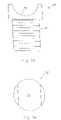
- FIGS. 1 and 2depict an embodiment of an implant of the invention which is adjustable in order to select the amount of distraction required.
- FIG. 1depicts the implant in a more extended configuration than does FIG. 2 .
- FIGS. 3 a and 3 bdepict side and end views of a first forked and of the embodiment of FIG. 1 .
- FIGS. 4 a and 4 bdepict side sectioned and end views of an interbody piece of the implant of FIG. 1 .
- FIGS. 5 a and 5 bdepict side and end views of a second forked end of the embodiment of FIG. 1 .
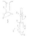
- FIGS. 6 , 7 , 8 , 9 and 10depict apparatus and method for another embodiment of the present invention for creating distraction between adjacent spinous processes.
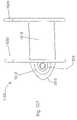
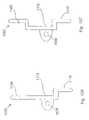
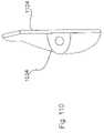
- FIGS. 11 , 12 and 13depict yet a further embodiment of the invention for creating distraction between adjacent spinous processes.
- FIGS. 14 and 15depict a further apparatus and method of an embodiment of the invention for creating distraction.
- FIGS. 16 , 16 a , and 17depict yet another embodiment of the present invention.
- FIGS. 18 , 19 and 20depict yet a further apparatus and method of the present embodiment.
- FIGS. 21 and 22depict still a further embodiment of the present invention.
- FIGS. 23 , 24 and 25depict another embodiment of the present invention.
- FIGS. 26 , 27 and 28depict another embodiment of the invention.
- FIGS. 29 and 30depict side elevational views of differently shaped implants of embodiments of the present invention.
- FIGS. 31 , 32 and 33depict various implant positions of an apparatus of the present invention.
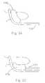
- FIGS. 34 and 35depict yet another apparatus and method of the present invention.
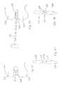
- FIGS. 36 , 37 and 38depict three different embodiments of the present invention.
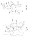
- FIGS. 39 and 40depict yet another apparatus and method of an embodiment of the present invention.
- FIGS. 41 , 42 and 43depict yet further embodiments of an apparatus and method of the present invention.
- FIG. 44is still a further embodiment of an implant of the invention.
- FIG. 45is yet another depiction of an apparatus and method of the invention.
- FIGS. 46 and 47depict still a further apparatus and method of an embodiment of the invention.
- FIGS. 48 , 49 , 50 and 51depict yet a further apparatus and method of the invention.
- FIGS. 52 , 53 , 54 , 55 a and 55 bdepict another apparatus and method of the invention.
- FIGS. 56 , 57 and 58depict yet a further apparatus and method of the invention.
- FIGS. 59 and 60depict still a further embodiment of the invention.
- FIG. 61depict another embodiment of the invention.
- FIGS. 62 and 63depict yet another embodiment of the present invention.
- FIGS. 64 and 65depict still a further embodiment of the present invention.
- FIG. 66depicts another embodiment of the invention.
- FIGS. 67 and 68depict yet another embodiment of the present invention.
- FIGS. 69 , 70 , 71 and 71 adepict a further embodiment of the present invention.
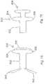
- FIGS. 72 and 73depict still another embodiment of the invention.
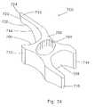
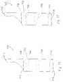
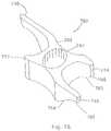
- FIGS. 74 , 75 , 76 , 77 , and 78depict still other embodiments of the invention.
- FIGS. 79 , 80 , 80 a , 81 , 82 , 83 , 83 a , 84 , 85 , 86 and 87depict still a further embodiment of the present invention.
- FIGS. 88 , 89 , 90 and 91depict yet another embodiment of the present invention.
- FIGS. 92 , 92 a , 92 b , 93 , 93 a , 93 b , 93 c , 93 d , 94 , 94 a , 94 b , 95 , 95 a , and 96depict still a further embodiment of the present invention wherein a sleeve is provided which is capable of deflecting response to relative motion between the spinous processes.
- FIG. 97depicts still another embodiment of the present invention.
- FIG. 98depicts yet a further embodiment of the present invention.
- FIGS. 99 and 100depict still another embodiment of the present invention including an insertion tool.
- FIGS. 101 , 102 , 102 a , 103 , 104 , 105 , 106 , and 107depict still a further embodiment of the present invention.
- FIGS. 108 , 109 , and 110depict still another embodiment of the present invention.
- FIGS. 111 , 112 , 113 , 114 , 115 , 116 , and 117depict yet another embodiment of the present invention.
- FIG. 118depicts a graph showing characteristics of a preferred material usable with several of the embodiments of the present invention.
- FIGS. 119 a and 119 bdepict side and plan views of still a further embodiment of the present invention.
- FIGS. 120 a and 120 bdepict side and plan views of the second wing which can be used in conjunction with the embodiment of the invention of FIGS. 119 a and 119 b.
- FIGS. 121 a and 121 bdepict side and plan views of the first wing and central body of the embodiment of the invention depicted in FIGS. 119 a and 119 b.
- FIGS. 122 a , 122 b , and 122 cdepict top, side and end views of a guide which is a portion of the embodiment of the invention of FIGS. 119 a and 119 b.
- FIGS. 123 a and 123 bdepict an end view and a cross-sectioned view respectfully of the sleeve of the embodiment of the invention of FIGS. 119 a and 119 b.
- FIGS. 124 a , 124 b and 124 cdepict a view of the embodiment of the invention of FIGS. 119 a and 119 b taken through line 124 - 124 in FIG. 119 b shown in with the sleeve in various positions relative to a first wing.
- FIG. 125depicts an alternative embodiment of the invention as depicted in FIGS. 119 a and 119 b.
- FIG. 126depicts yet a further alternative embodiment of the invention depicted in FIGS. 119 a and 119 b.
- FIG. 127depicts yet a further embodiment of the invention as depicted in FIGS. 119 a and 119 b.
- FIG. 128is still a further embodiment of the invention as depicted in FIG. 93 a.
- FIG. 129depicts still a further embodiment of the invention as depicted in FIGS. 119 a and 119 b.
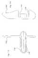
- FIG. 130is a perspective view of a first embodiment of the invention.
- FIG. 131is an exploded view of the embodiment of the invention of FIG. 130 .
- FIGS. 131 a and 131 bare alternative components of the embodiment of FIG. 131 .
- FIG. 132is a plan view of the embodiment of the invention of FIG. 130 .
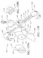
- FIGS. 133 a , 133 b , 133 c , and 133 dare perspective, first end, second end, and sectional views of a spacer or sleeve of the embodiment of the invention depicted in FIG. 130 .
- FIG. 134is a cross sectional view of an embodiment of the invention taken through line 134 - 134 in FIG. 132 .
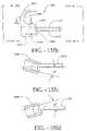
- FIGS. 135 a - 135 fare various views of an embodiment of the hook mechanism of the embodiment of the invention of FIG. 130 .
- FIG. 136is a schematical representation of an embodiment of the invention as positioned with respect to adjacent spinous processes.
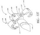
- FIG. 137is a perspective view of another embodiment of the invention.
- FIG. 138is an exploded view of the embodiment of the invention of FIG. 137 .
- FIG. 138 ais an alternative component of the embodiment of FIG. 137 .
- FIG. 138 bis an upside down perspective view of a component of the embodiment of FIG. 138 .
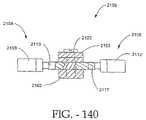
- FIG. 139is a plan view of the embodiment of the invention of FIG. 137 .
- FIG. 140is a partial section view taken through line 140 - 140 of FIG. 139 .
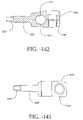
- FIG. 141is an exploded view of yet another embodiment of the invention.
- FIG. 141 ais an upside down perspective view of a component of the embodiment of FIG. 141 .
- FIG. 142is a sectional view of a body portion of the embodiment of the invention of FIG. 141 taken through line 142 - 142 .
- FIG. 143is a top view of the body portion shown in FIG. 142 .
- FIG. 144is a sectional view of yet another embodiment of a body portion of the invention.
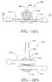
- FIG. 145is a perspective view of yet a further embodiment of the body portion of the invention.
- FIGS. 146 a , 146 b , and 146 cdepict yet a further embodiment of a body portion of the invention.
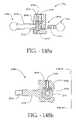
- FIGS. 147 a and 147 bare side and top views of yet another embodiment of the invention depicting a mechanism for adjusting the positions of the hook mechanisms of, for example, the embodiment of the invention of FIGS. 130 , 137 , and 141 .
- FIGS. 148 a and 148 bare sectional top and side views of yet another embodiment of the invention for adjusting the position of the hook mechanisms.
- FIGS. 149 a and 149 bare perspective and side views of yet a further mechanism of an embodiment of the invention for adjusting the position of hook mechanisms of the invention.
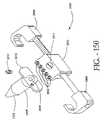
- FIG. 150is a perspective view of yet a further embodiment of the invention.
- FIG. 151is a perspective view of an embodiment of the invention which is addressable to multiple levels of spinous processes.
- FIG. 152is a perspective view of an alternative embodiment of the supplemental spine fixation device of the invention.
- FIG. 153is an exploded view of the embodiment of the invention of FIG. 152 .
- FIG. 154 ais a sectioned view of the spacer and lead-in nose tissue expander of the invention.
- FIG. 154 bis an end view of a spacer of FIG. 154 a.
- FIG. 154 cis an exploded view of several of the components of FIG. 154 a.
- FIG. 155 ais a plan, partially sectioned view of an embodiment of a hook of the invention.
- FIG. 155 bis a sectioned view taken through line 155 b - 155 b of FIG. 155 a.
- FIG. 155 cis a sectioned view taken through line 155 c - 155 c of FIG. 155 a.
- FIG. 155 dis a bottom view of the embodiment of the hook of the invention of 155 a.
- FIG. 155 eis an end view of FIG. 155 d.
- FIG. 156is a view of an embodiment of a shaft arrangement of the invention upon which hooks can be mounted.
- FIG. 157is an alternate view of the top member of the hub showing the locking mechanism.
- FIGS. 158 a and 158 bare sectioned views of an alternate embodiment of the hub mechanism of the invention.
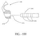
- FIG. 159is an alternate embodiment of the hook attached to a shaft of the invention.
- FIG. 160is an alternate embodiment of a sleeve of the invention positioned between adjacent spinous processes.
- FIGS. 1 to 129are directed to spine distraction implant and method used in distracting apart spinous processes in order to relieve pain associated with the spine such as, by way of example only, the pain associated with spinal stenosis. Accordingly, as appropriate, and even if not specifically mentioned in each inventive description of FIGS. 130 to 160 , many of the design characteristics, features, functionalities, materials, measurements, dimensions, purposes, aspects, and objects of the devices in FIGS. 1 to 129 are applicable to the present invention.
- Implant 20includes first and second forked ends 22 and 24 , each defining a saddle 26 , 28 respectively.
- the forked ends 22 , 24are mated using an interbody piece 30 .
- the first forked end 22includes a threaded shaft 32 which projects rearwardly from the saddle 26 .
- the threaded shaft 32fits into the threaded bore 34 ( FIG. 4 a ) of the interbody piece 30 .
- the second forked end 24( FIGS. 5 a , 5 b ) includes a smooth cylindrical shaft 36 which can fit into the smooth bore 38 of the interbody piece 30 .
- FIG. 1shows the implant 20 in a fully extended position
- FIG. 2shows the implant in an unextended position.
- the threaded shaft 32 of the first forked end 22fits inside the hollow cylindrical shaft 36 of the second forked end 24 .
- the implant 20For purposes of implantation between adjacent first and second spinous processes of the spinal column, the implant 20 is configured as shown in FIG. 2 .
- the first and second spinous processesare exposed using appropriate surgical techniques and thereafter, the implant 20 is positioned so that saddle 26 engages the first spinous process, and saddle 28 engages the second spinous process.
- the interbody piece 30can be rotated by placing an appropriate tool or pin into the cross holes 40 and upon rotation, the saddle 26 is moved relative to the saddle 28 .
- Such rotationspreads apart or distracts the spinous processes with the resultant and beneficial effect of enlarging the volume of the spinal canal in order to alleviate any restrictions on blood vessels and nerves.
- this implantas well as the several other implants described herein act as an extension stop. That means that as the back is bent backwardly and thereby placed in extension the spacing between adjacent spinous processes cannot be reduced to a distance less than the distance between the lowest point of saddle 26 and the lowest point of saddle 28 .
- This implantdoes not inhibit or in anyway limit the flexion of the spinal column, wherein the spinal column is bent forward.
- such a deviceprovides for distraction in the range of about 5 mm to about 15 mm.
- devices which can distract up to and above 22 mmmay be used depending on the characteristics of the individual patient.
- the implant 20can be implanted essentially floating in position in order to gain the benefits of the aforementioned extension stop and flexion non-inhibitor.
- one of the saddles 26can be laterally pinned with pin 29 to one of the spinous processes and the other saddle can be loosely associated with the other spinous processes by using a tether 31 which either pierces or surrounds the other spinous process and then is attached to the saddle in order to position the saddle relative to the spinous process.
- both saddlescan be loosely tethered to the adjacent spinous process in order to allow the saddles to move relative to the spinous processes.
- the shape of the saddlesbeing concave, gives the advantage of distributing the forces between the saddle and the respective spinous process. This ensures that the bone is not resorbed due to the placement of the implant 20 and that the structural integrity of the bone is maintained.
- the implant 20 in this embodimentcan be made of a number of materials, including but not limited to, stainless steel, titanium, ceramics, plastics, elastics, composite materials or any combination of the above.
- the modulus of elasticity of the implantcan be matched to that of bone, so that the implant 20 is not too rigid.
- the flexibility of the implantcan further be enhanced by providing additional apertures or perforations throughout the implant in addition to the holes 40 which also have the above stated purpose of allowing the interbody piece 30 to be rotated in order to expand the distance between the saddle 26 , 28 .
- the spinous processescan be accessed and distracted initially using appropriate instrumentation, and that the implant 20 can be inserted and adjusted in order to maintain and achieve the desired distraction.
- the spinous processcan be accessed and the implant 20 appropriately positioned. Once positioned, the length of the implant can be adjusted in order to distract the spinous processes or extend the distraction of already distracted spinous processes.
- the implantcan be used to create a distraction or to maintain a distraction which has already been created.
- implant 20placement of implants such as implant 20 relative to the spinous process will be discussed hereinbelow with other embodiments. However, it is to be noted that ideally, the implant 20 would be placed close to the instantaneous axis of rotation of the spinal column so that the forces placed on the implant 20 and the forces that the implant 20 places on the spinal column are minimized.
- the methoduses the approach of extending the length of the implant 20 a first amount and then allowing the spine to creep or adjust to this distraction. Thereafter, implant 20 would be lengthened another amount, followed by a period where the spine is allowed to creep or adjust to this new level of distraction. This process could be repeated until the desired amount of distraction has been accomplished.
- This same methodcan be used with insertion tools prior to the installation of an implant. The tools can be used to obtain the desired distraction using a series of spinal distraction and spine creep periods before an implant is installed.
- FIGS. 6 , 7 , 8 , 9 and 10includes distraction or spreader tool 50 which has first and second arms 52 , 54 .
- Arms 52 , 54are pivotal about pivot point 56 and releaseable from pivot point 56 in order to effect the implantation of implant 58 .
- the arms 52 , 54are somewhat concave in order to cradle and securely hold the first spinous process 60 relative to arm 52 and the second spinous process 62 relative to arm 54 .
- the distraction tool 50can be inserted through a small incision in the back of the patient in order to address the space between the first spinous process 60 and the second spinous process 62 .
- the arms 52 , 54can be spread apart in order to distract the spinous processes.
- an implant 58 as shown in FIGS. 8 and 9can be urged between the arms 52 , 54 and into position between the spinous processes.
- the arms 52 , 54can be withdrawn from the spinous processes leaving the implant 58 in place.
- the implant 58is urged into place using a tool 64 which can be secured to the implant 58 through a threaded bore 66 in the back of the implant. As can be seen in FIG.
- the implant 58includes saddles 68 and 70 which cradle the upper and lower spinous processes 60 , 62 in much the same manner as the above first embodiment and also in much the same manner as the individual arms of the tool 50 .
- the saddles as described abovetend to distribute the load between the implant and the spinous processes and also assure that the spinous process is stably seated at the lowest point of the respective saddles.
- the spreader or distraction tool 80includes first and second arms 82 , 84 which are permanently pivoted at pivot point 86 .
- the armsinclude L-shaped ends 88 , 90 .
- the L-shaped ends 88 , 90can be inserted between the first and second spinous processes 92 , 94 .
- the arms 82 , 84can be spread apart in order to distract the spinous processes.
- the implant 96can then be urged between the spinous processes in order to maintain the distraction. It is noted that implant 96 includes wedged surfaces or ramps 98 , 100 .
- the rampsfurther cause the spinous processes to be distracted.
- the full distractionis maintained by the planar surfaces 99 , 101 located rearwardly of the ramps. It is to be understood that the cross-section of the implant 96 can be similar to that shown for implant 58 or similar to other implants in order to gain the advantages of load distribution and stability.
- the implant 110includes first and second conically shaped members 112 , 114 .
- Member 112includes a male snap connector 116 and member 114 includes a female snap connector 118 .
- male snap connector 116urged into female snap connector 118
- the first member 112is locked to the second member 114 .
- a distraction or spreader tool 80could be used.
- an implantation tool 120can be used to position and snap together the implant 110 .
- the first member 112 of implant 110is mounted on one arm and second member 114 is mounted on the other arm of tool 120 .
- the member 112 , 114are placed on opposite sides of the space between adjacent spinous processes.
- the members 112 , 114are urged together so that the implant 110 is locked in place between the spinous processes as shown in FIG. 15 .
- the implant 110can also be made more self-distracting by causing the cylindrical surface 122 to be more conical, much as surface 124 is conical, in order to hold implant 110 in place relative to the spinous processes and also to create additional distraction.
- FIGS. 16 and 17An alternative embodiment of the implant can be seen in FIGS. 16 and 17 .
- This implant 130includes first and second members 132 , 134 .
- the implantsare held together using a screw (not shown) which is inserted through countersunk bore 136 and engages a threaded bore 138 of the second member 134 .
- Surfaces 139are flattened ( FIG. 17 ) in order to carry and spread the load applied thereto by the spinous processes.
- the embodiment of implant 130is not circular in overall outside appearance, as is the embodiment 110 of FIGS. 14 and 15 .
- this embodimentis truncated so that the lateral side 140 , 142 are flattened with the upper and lower sides 144 , 146 being elongated in order to capture and create a saddle for the upper and lower spinous processes.
- the upper and lower sides, 144 , 146are rounded to provide a more anatomical implant which is compatible with the spinous processes.
- key 148 and keyway 150are designed to mate in a particular manner.
- Key 148includes at least one flattened surface, such as flattened surface 152 , which mates to an appropriately flattened surface 154 of the keyway 150 .
- the first memberis appropriately mated to the second member in order to form appropriate upper and lower saddles holding the implant 130 relative to the upper and lower spinous processes.
- FIG. 16 adepicts second member 134 in combination with a rounded nose lead-in plug 135 .
- Lead-in plug 135includes a bore 137 which can fit snugly over key 148 .
- the lead-in plug 135can be used to assist in the placement of the second member 134 between spinous processes. Once the second member 134 is appropriately positioned, the lead-in plug 135 can be removed. It is to be understood that the lead-in plug 135 can have other shapes such as pyramids and cones to assist in urging apart the spinous processes and soft tissues in order to position the second member 134 .
- the implant 330 as shown in FIG. 18is comprised of first and second mating wedges 332 and 334 .
- the spinous processesare accessed from both sides and then a tool is used to push the wedges towards each other.
- the wedgesmove relative to each other so that the combined dimension of the implant 330 located between the upper and lower spinous processes 336 , 338 ( FIG. 20 ), increases, thereby distracting the spinous processes.
- the wedges 332 , 334include saddle 340 , 342 , which receiving the spinous processes 336 , 338 . These saddles have the advantages as described hereinabove.
- the first or second wedges 332 , 334have a mating arrangement which includes a channel 344 and a projection of 346 which can be urged into the channel in order to lock the wedges 332 , 334 together.
- the channel 334is undercut in order to keep the projection from separating therefrom.
- a detentcan be located in one of the channel and the projection, with a complimentary recess in the other of the channel and the projection. Once these two snap together, the wedges are prevented from sliding relative to the other in the channel 344 .
- the implant 370is comprised of first and second distraction cone 372 , 374 . These cones are made of a flexible material. The cones are positioned on either side of the spinous processes 376 , 378 as shown in FIG. 21 . Using appropriate tool as shown hereinabove, the distraction cones 372 , 374 are urged together. As they are urged together, the cones distract the spinous processes as shown in FIG. 22 . Once this has occurred, an appropriate screw or other type of fastening mechanism 380 can be used to maintain the position of the distraction cones 372 , 374 . The advantage of this arrangement is that the implant 370 is self-distracting and also that the implant, being flexible, molds about the spinous processes as shown in FIG. 22 .
- FIGS. 23 and 24another embodiment of the implant 170 is depicted.
- This implantis guided in place using an L-shaped guide 172 which can have a concave cross-section such as the cross-section 52 of retraction tool 50 in FIG. 6 in order to cradle and guide the implant 170 in position.
- an L-shaped guide 172which can have a concave cross-section such as the cross-section 52 of retraction tool 50 in FIG. 6 in order to cradle and guide the implant 170 in position.
- a small incisionwould be made into the back of the patient and the L-shaped guide tool 172 inserted between the adjacent spinous processes.
- the implant 170would be mounted on the end of insertion tool 174 and urged into position between the spinous processes. The act of urging the implant into position could cause the spinous processes to be further distracted if that is required.
- a distraction toolsuch as shown in FIG. 13 could be used to initially distract the spinous processes.
- Implant 170can be made of a deformable material so that it can be urged into place and so that it can somewhat conform to the shape of the upper and lower spinous processes.
- This deformable materialwould be preferably an elastic material. The advantage of such a material would be that the load forces between the implant and the spinous processes would be distributed over a much broader surface area. Further, the implant would mold itself to an irregular spinous process shape in order to locate the implant relative to spinous processes.
- this implant 176can be inserted over a guide wire, guide tool or stylet 178 .
- the guide wire 178is positioned through a small incision to the back of the patient to a position between the adjacent spinous processes.
- the implantis threaded over the guide wire 178 and urged into position between the spinous processes. This urging can further distract the spinous processes if further distraction is required.
- the guide tool 178is removed and the incision closed.
- the insertion tools of FIGS. 23 and 24can also be used if desired.
- FIGS. 26 , 27 and 28uses an implant similar to that depicted in FIGS. 8 and 9 with different insertion tools.
- an L-shaped distraction tool 190is similar to L-shaped distraction tool 80 ( FIG. 12 ), is used to distract the first and second spinous processes 192 , 194 .
- an insertion tool 196is placed between the spinous processes 192 , 194 .
- Insertion tool 196includes a handle 198 to which is mounted a square-shaped ring 200 .
- the distraction tool 190can be inserted through a small incision in the back in order to spread apart the spinous processes.
- an upper end 202 of ring 200can be initially inserted followed by the remainder of the ring 200 .
- the ringcan be rotated slightly by moving handle 198 downwardly in order to further wedge the spinous processes apart.
- an implantsuch as implant 204 can be inserted through the ring and properly positioned using implant handle 206 . Thereafter, the implant handle 206 and the insertion tool 196 can be removed.
- the implants 210 , 212can have different shapes when viewed from the side. These implants are similar to the above-referenced implants 58 ( FIG. 8) and 204 ( FIG. 28 ). These implants have cross-sections similar to that shown in FIG. 10 which includes saddles in order to receive and hold the adjacent spinous processes.
- these implantscan be placed in different positions with respect to the spinous process 214 .
- the implant 210is placed closest to the lamina 216 . Being so positioned, the implant 210 is close to the instantaneous axis of rotation 218 of the spinal column, and the implant would experience least forces caused by movement of the spine. Thus, theoretically, this is the optimal location for the implant.
- the implantcan be placed midway along the spinous process ( FIG. 32 ) and towards the posterior aspect of the spinous process ( FIG. 31 ). As positioned shown in FIG. 31 , the greatest force would be placed on the implant 210 due to a combination of compression and extension of the spinal column.
- implant 220is comprised of a plurality of individual leaves 222 which are substantially V-shaped.
- the leavesinclude interlocking indentations or detents 224 . That is, each leaf includes an indentation with a corresponding protrusion such that a protrusion of one leaf mates with an indentation of an adjacent leaf.
- an insertion tool 226which has a blunt end 228 which conforms to the shape of an individual leaf 222 . For insertion of this implant into the space between the spinous processes as shown in FIG. 29 , the insertion tool 226 first insert a single leaf 220 .
- the insertion toolthen inserts a second leaf with the protrusion 224 of the second leaf snapping into corresponding indentation made by the protrusion 224 of the first leaf.
- This processwould reoccur with third and subsequent leaves until the appropriate spacing between the spinous processes was built up.
- the lateral edges 229 of the individual leaves 222are slightly curved upwardly in order to form a saddle for receiving the upper and lower spinous processes.
- FIGS. 36 , 37 and 38which include implants 230 , 232 , and 234 respectively, are designed in such a manner so the implant locks itself into position once it is properly positioned between the spinous processes.
- Implant 220is essentially a series of truncated cones and includes a plurality of ever expanding steps 236 . These steps are formed by the conical bodies starting with the nose body 238 followed there behind by conical body 240 . Essentially, the implant 234 looks like a fir tree placed on its side.
- the implant 230is inserted laterally throughout the opening between upper and lower spinous processes.
- the first body 238causes the initial distraction. Each successive conical body distracts the spinous processes a further incremental amount.
- the spinous processesare locked into position by steps 236 .
- the initial nose body 238 of the implant and other bodies 240can be broken, snapped or sawed off if desired in order to minimize the size of the implant 230 .
- the intersection between bodiessuch as body 238 and 240 , which is intersection line 242 , would be somewhat weaken with the appropriate removal of material. It is noted that only the intersection lines of the initial conical bodies need to be so weakened. Thus, intersection line 244 between the bodies which remain between the spinous processes would not need to be weaker, as there would be no intention that the implant would be broken off at this point.
- FIG. 37shows implant 232 positioned between upper and lower spinous processes.
- This implantis wedge-shaped or triangular shaped in cross-sectioned and includes bore pluralities 245 and 246 . Through these bores can be placed locking pins 248 and 250 .
- the triangular or wedged-shaped implantcan be urged laterally between and thus distract the upper and lower spinous processes. Once the appropriate distraction is reached, pins 248 , 250 can be inserted through the appropriate bores of the bore pluralities 245 and 246 in order to lock the spinous processes in a V-shaped valley formed by pins 248 , 250 on the one hand and the ramped surface 233 , 235 on the other hand.
- the implant 234has a triangular-shaped or wedge-shaped body similar to that shown in FIG. 32 .
- tab 252 , 254are pivotally mounted to the triangular shaped body 234 .
- cannula 258is inserted through a small incision to a position between upper and lower spinous processes. Once the cannula is properly inserted, an implant 260 is pushed through the cannula 258 using an insertion tool 262 .
- the implant 260includes a plurality of ribs or indentation 264 that assist in positioning the implant 260 relative to the upper and lower spinal processes. Once the implant 260 is in position, the cannula 258 is withdrawn so that the implant 260 comes in contact with and wedges between the spinous processes.
- the cannula 258is somewhat conical in shape with the nose end 266 being somewhat smaller than the distal end 268 in order to effect the insertion of the cannula into the space between the spinous processes.
- a plurality of cannulacan be used instead of one, with each cannula being slightly bigger than one before.
- the first smaller cannulawould be inserted followed by successively larger cannula being placed over the previous smaller cannula.
- the smaller cannulawould then be withdrawn from the center of the larger cannula. Once the largest cannula is in place, and the opening of the skin accordingly expanded, the implant, which is accommodated by only the larger cannula, is inserted through the larger cannula and into position.
- the precurved implant 270 in FIGS. 41 and 42 , and precurved implant 272 in FIG. 43have common introduction techniques which includes a guide wire, guide tool, or stylet 274 .
- the guide wire 274is appropriately positioned through the skin of the patient and into the space between the spinous processes. After this is accomplished, the implant is directed over the guide wire and into position between the spinous processes.
- the precurved nature of the implantassist in (1) positioning the implant through a first small incision in the patient's skin on one side of the space between two spinous processes and (2) guiding the implant toward a second small incision in the patient's skin on the other side of the space between the two spinous processes.
- the implantincludes a conical introduction nose 276 and a distal portion 278 .
- the nose 276As the nose 276 is inserted between the spinous processes, this causes distraction of the spinous processes.
- Break lines 280 , 282are established at opposite sides of the implant 270 . Once the implant is properly positioned over the guide wire between the spinous processes, the nose portion 276 and the distal portion 278 can be broken off along the break lines, through the above two incisions, in order to leave the implant 270 in position.
- break lines 280 , 282can be provided on implant 270 so that the implant can continue to be fed over the guide wire 278 until the appropriate width of the implant 270 creates the desired amount of distraction.
- the break linescan be created by perforating or otherwise weakening the implant 270 so that the appropriate portions can be snapped or sawed off.
- this implantis similar in design to the implant 230 shown in FIG. 36 .
- This implant 272 in FIG. 47is precurved and inserted over a guide wire 274 to a position between the spinous processes.
- sections of the implant 272can be broken, snapped or sawed off as described hereinabove in order to leave a portion of the implant wedged between the upper and lower spinous processes.
- FIG. 44A further embodiment of the invention is shown in FIG. 44 .
- This embodimentincludes a combination insertion tool and implant 290 .
- the insertion tool and implant 290is in the shape of a ring which is hinged at point 292 .
- the ringis formed by a first elongated and conically shaped member 294 and a second elongated and conically shaped member 296 .
- Members 294 and 296terminate in points and through the use of hinge 292 are aligned and meet.
- first member and second memberare inserted through the skins of the patient and are mated together between the spinous processes.
- the implant 290is rotated, for example clockwise, so that increasingly widening portions of the first member 292 are used to distract the first and second spinous processes.
- the remainder of the ring before and after the section which is located between the spinous processescan be broken off as taught hereinabove in order to maintain the desired distraction.
- the entire ringcan be left in place with the spinous processes distracted.
- the implant 300is comprised of a plurality of rods or stylets 302 which are inserted between the upper and lower spinous processes.
- the rodsare designed much as described hereinabove so that they may be broken, snapped or cut off. Once these are inserted and the appropriate distraction has been reached, the stylets are broken off and a segment of each stylet remains in order to maintain distraction of the spinous process.
- Implant 310 of FIGS. 46 and 47is comprised of a shape memory material which coils upon being released.
- the materialis straightened out in a delivery tool 312 .
- the delivery toolis in position between upper and lower spinous processes 314 , 316 .
- the materialis then pushed through the delivery tool. As it is released from the delivery end 318 of the delivery tool, the material coils, distracting the spinous processes to the desired amount. Once this distraction has been achieved, the material is cut and the delivery tool removed.
- the implant 320is delivered between upper and lower spinous processes 322 and 324 , by delivery tool 326 .
- the delivery toolis given a 90° twist so that the implant goes from the orientation as shown in FIG. 49 , with longest dimension substantially perpendicular to the spinous processes, to the orientation shown in FIG. 50 where the longest dimension is in line with and parallel to the spinous processes.
- This rotationcauses the desired distraction between the spinous processes.
- Implant 320includes opposed recesses 321 and 323 located at the ends thereof. Rotation of the implant 320 causes the spinous processes to become lodged in these recesses.
- the insertion tool 326can be used to insert multiple implants 320 , 321 into the space between the spinous processes 322 , 324 ( FIG. 51 ). Multiple implants 320 , 321 can be inserted until the appropriate amount of distraction is built up. It is to be understood in this situation that one implant would lock to another implant by use of, for example, a channel arrangement wherein a projection from one of the implants would be received into and locked into a channel of the other implant. Such a channel arrangement is depicted with respect to the other embodiment.
- FIGS. 52 through 55 bis comprised of a fluid-filled dynamic distraction implant 350 .
- This implantincludes a membrane 352 which is placed over pre-bent insertion rod 354 and then inserted through an incision on one side of the spinous process 356 .
- the bent insertion rod, with the implant 350 thereover,is guided between appropriate spinous processes. After this occurs, the insertion rod 354 is removed leaving the flexible implant in place.
- the implant 350is then connected to a source of fluid (gas, liquid, gel and the like) and the fluid is forced into the implant causing it to expand as shown in FIG. 54 , distracting the spinal processes to the desired amount.
- the implant 350is closed off as is shown in FIG. 55 a .
- the implant 350being flexible, can mold to the spinous processes which may be of irregular shape, thus assuring positioning. Further, implant 350 acts as a shock absorber, damping forces and stresses between the implant and the spinous processes.
- a variety of materialscan be used to make the implant and the fluid which is forced into the implant.
- viscoelastic substancessuch as methylcellulose, or hyaluronic acid can be used to fill the implant.
- materials which are initially a fluid, but later solidifycan be inserted in order to cause the necessary distraction. As the materials solidify, they mold into a custom shape about the spinous processes and accordingly are held in position at least with respect to one of two adjacent spinous processes.
- the implantcan be formed about one spinous process in such a manner that the implant stays positioned with respect to that spinous process ( FIG. 55 b ).
- a single implantcan be used as an extension stop for spinous process located on either side, without restricting flexion of the spinal column.
- the implant 360 as shown in FIG. 56is comprised of a shape memory material such as a plastic or a metal.
- a curved introductory tool 362is positioned between the appropriate spinous processes as described hereinabove. Once this has occurred, bore 364 of the implant is received over the tool. This act can cause the implant to straighten out. The implant is then urged into position and thereby distracts the spinous processes. When this has occurred, the insertion tool 362 is removed, allowing the implant to assume its pre-straightened configuration and is thereby secured about one of the spinous processes.
- the implantcan be temperature sensitive. That is to say that the implant would be more straightened initially, but become more curved when it was warmed by the temperature of the patient's body.
- the implant 380is comprised of a plurality of interlocking leaves 382 . Initially, a first leaf is positioned between opposed spinous processes 384 , 386 . Then subsequently, leafs 382 are interposed between the spinous processes until the desired distraction has been built up. The leaves are somewhat spring-like in order to absorb the shock and can somewhat conform to the spinous processes.
- the implant 390 of FIG. 61includes the placement of shields 392 , 394 over adjacent spinous processes 396 , 398 .
- the shieldsare used to prevent damage to the spinous processes.
- These shieldsinclude apertures which receives a self-tapping screw 400 , 402 .
- the shieldsare affixed to the spinous processes and the spinous processes are distracted in the appropriate amount. Once this has occurred, a rod 404 is used to hold the distracted position by being screwed into each of the spinous processes through the aperture in the shields using the screws as depicted in FIG. 61 .
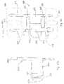
- Implant 410 of FIGS. 62 , 63is comprised of first and second members 412 , 414 which can be mated together using an appropriate screw and threaded bore arrangement to form the implant 410 .
- Main member 412 and mating member 414form implant 410 .
- the implant 410would have a plurality of members 414 for use with a standardized first member 412 .
- FIGS. 62 and 64show different types of mating members 414 .
- the mating member 414includes projections 416 and 418 which act like shims. These projections are used to project into the space of saddles 420 , 422 of the first member 412 .
- These projections 416 , 418can be of varying lengths in order to accommodate different sizes of spinous processes.
- a groove 424is placed between the projections 416 , 418 and mates with an extension 426 of the first member 412 .
- FIGS. 64 , 65 and 66are similar in design and concept to the embodiment of FIGS. 62 and 63 .
- the implant 500includes the first and second members 502 , 504 . These members can be secured together with appropriate screws or other fastening means as taught in other embodiments.
- Implant 500includes first and second saddles 506 , 508 which are formed between the ends of first and second members 502 , 504 . These saddles 506 , 508 are used to receive and cradle the adjacent spinous processes. As can be seen in FIG. 64 , each saddle 506 , 508 is defined by a single projection or leg 510 , 512 , which extends from the appropriate first and second members 502 , 504 .
- each of the saddlesis defined by only a single leg as the ligaments and other tissues associated with the spinous processes can be used to ensure that the implant is held in an appropriate position.
- FIG. 64it is easier to position the implant relative to the spinous processes as each saddle is defined by only a single leg and thus the first and second members can be more easily worked into position between the various tissues.
- the implant 520is comprised of a single piece having saddles 522 and 524 .
- the saddlesare defined by a single leg 526 , 528 respectively.
- an incisionis made between lateral sides of adjacent spinous processes.
- the single leg 526is directed through the incision to a position adjacent to an opposite lateral side of the spinous process with the spinous process cradled in the saddle 522 .
- the spinous processesare then urged apart until saddle 524 can be pivoted into position into engagement with the other spinous process in order to maintain the distraction between the two adjacent spinous processes.
- FIG. 66is similar to that of FIG. 65 with an implant 530 and first and second saddles 532 and 534 .
- a tether 536 , 538Associated with each saddle is a tether 536 , 538 respectively.
- the tethersare made of flexible materials known in the trade and industry and are positioned through bores in the implant 530 . Once appropriately positioned, the tethers can be tied off. It is to be understood that the tethers are not meant to be used to immobilize one spinous process relative to the other, but are used to guide motion of the spinous processes relative to each other so that the implant 530 can be used as an extension stop and a flexion non-inhibitor.
- the saddles 532 , 534are used to stop spinal column backward bending and extension. However, the tethers do not inhibit forward bending and spinal column flexion.
- the implant 550is Z-shaped and includes a central body 552 and first and second arms 554 , 556 , extending in opposite directions therefrom.
- the central body 552 of the implant 550includes first and second saddles 558 and 560 .
- the first and second saddles 558 and 560would receive upper and lower spinous processes 562 , 568 .
- the arms 554 , 556are accordingly located adjacent the distal end 566 ( FIG. 68 ) of the central body 552 .
- the first and second arms 554 , 556act to inhibit forward movement, migration or slippage of the implant 550 toward the spinal canal and keep the implant in place relative to the first and second spinal processes. This prevents the implant from pressing down on the ligamentum flavum and the dura.
- the central bodywould have a height of about 10 mm with each of the arms 554 , 556 have a height of also about 10 mm. Depending on the patient, the height of the body could vary from about less than 10 mm to about greater than 24 mm.
- the first and second arms 554 , 556are additionally contoured in order to accept the upper and lower spinous processes 556 , 558 .
- the arms 554 , 556 as can be seen with respect to arm 554have a slightly outwardly bowed portion 568 ( FIG. 68 ) with a distal end 570 which is slightly inwardly bowed.
- This configurationallows the arm to fit about the spinous process with the distal end 570 somewhat urged against the spinous process in order to guide the motion of the spinous process relative to the implant.
- These arms 554 , 556could if desired to be made more flexible than the central body 552 by making arms 554 , 556 thin and/or with perforations, and/or other material different than that of the central body 550 .
- this embodimentcan be urged into position between adjacent spinous processes by directing an arm into a lateral incision so that the central body 552 can be finally positioned between spinous processes.
- FIGS. 69 , 70 and 71are perspective front, end, and side views of implant 580 of the invention.
- This implantincludes a central body 582 which has first and second saddles 584 , 586 for receiving adjacent spinous processes. Additionally, the implant 580 includes first and second arms 588 and 590 . The arms, as with the past embodiment, prevent forward migration or slippage of the implant toward the spinal canal.
- First arm 588projects outwardly from the first saddle 584 and second arm 590 projects outwardly from the second saddle 586 .
- the first arm 588is located adjacent to the distal end 600 of the central body 582 and proceeds only partly along the length of the central body 582 .
- the first arm 588is substantially perpendicular to the central body as shown in FIG. 70 . Further, the first arm 588 , as well as the second arm 590 , is anatomically rounded.
- the second arm 590projecting from second saddle 586 , is located somewhat rearward of the distal end 600 , and extends partially along the length of the central body 582 .
- the second arm 590projects at a compound angle from the central body 582 .
- the second arm 590is shown to be at about an angle of 45° from the saddle 586 ( FIG. 70 ).
- the second arm 590is at an angle of about 45° relative to the length of the central body 580 as shown in FIG. 71 . It is to be understood that other compound angles are within the spirit and scope of the invention as claimed.
- the first and second arms 588 , 590have a length which is about the same as the width of the central body 582 .
- the length of each armis about 10 mm and the width of the central body is about 10 mm.
- the bodies with the widths of 24 mm and greaterare within the spirit and scope of the invention, along with first and second arms ranging from about 10 mm to greater than about 24 mm.
- the embodimentcould include a central body having a width of about or greater than 24 mm with arms being at about 10 mm.
- FIGS. 69 , 70 and 71are designed to preferably be positioned between the L4-L5 and the L5-S1 vertebral pairs.
- the embodiment of FIGS. 69 , 70 , 71is particularly designed for the L5-S1 position with the arms being designed to conform to the sloping surfaces found therebetween. The first and second arms are thus contoured so that they lie flat against the lamina of the vertebra which has a slight angle.
- FIGS. 69 , 70 , and 71as with the embodiment of FIGS. 67 and 68 is Z-shaped in configuration so that it may be inserted from one lateral side to a position between adjacent spinous processes. A first arm, followed by the central body, is guided through the space between the spinous processes. Such an arrangement only requires that a incision on one side of the spinous process be made in order to successfully implant the device between the two spinous processes.
- the implant 610 of FIG. 71 ais similar to that immediately above with the first arm 612 located on the same side of the implant as the second arm 614 .
- the first and second saddle 616 , 618are slightly modified in that distal portion 620 , 622 are somewhat flattened from the normal saddle shape in order to allow the implant to be positioned between the spinous processes from one side. Once in position, the ligaments and tissues associated with the spinous processes would hold the implant into position. Tethers also could be used if desired.
- Implant 630is also designed so that it can be inserted from one side of adjacent spinous processes.
- This insert 630includes a central body 632 with the first and second arms 634 , 636 extending on either side thereof.
- a plunger 638is positioned to extend from an end of the central body 632 .
- the plunger 638is fully extended and as shown in FIG. 73 , the plunger 638 is received within the central body 632 of the implant 630 .
- the third and fourth arms or hooks 640 , 642can extend outwardly from the central body 632 .
- the third and fourth arms or hooks 640 , 642can be comprised of a variety of materials, such as for example, shape memory metal materials or materials which have a springy quality.
- the plunger 638is pulled outwardly as shown in FIG. 72 .
- the central body 632is then positioned between adjacent spinous processes and the plunger 638 is allowed to move to the position of FIG. 73 so that the third and fourth arms 640 , 642 can project outwardly from the central body 632 in order to hold the implant 630 in position between the spinous processes.
- Plunger 638can be spring biased to the position as shown in FIG. 73 or can include detents or other mechanisms which lock it into that position. Further, the third and fourth arms themselves, as deployed, can keep the plunger in the position as shown in FIG. 73 .
- FIGS. 74 through 78Other embodiments of the invention are shown in FIGS. 74 through 78 .
- FIGS. 74 , 75 and 76disclose implant 700 .
- Implant 700is particularly suited for implantation between the L4-L5 and L5-S1 vertebra.
- the implant 700includes a central body 702 which has a bore 704 provided therein.
- Bore 704is used in order to adjust the modulus of elasticity of the implant so that it is preferably approximately two times the anatomical load placed on the vertebra in extension.
- the implant 700is approximately two times stiffer than the normal load placed on the implant.
- Such an arrangementis made in order to ensure that the implant is somewhat flexible in order to reduce potential resorption of the bone adjacent to the implant.
- Other modulus valuescan be used and be within the spirit of the invention.
- Implant 700includes first and second saddle 706 , 708 which are used to receive and spread the load from the upper and lower spinous processes.
- the saddle 706is defined by first and second arms 710 and 712 .
- the second saddle 708is defined by third and fourth arms 714 and 716 .
- the first arm 710in a preferred embodiment, is approximately two times the length of the body 702 with the second arm being approximately less than a quarter length of the body.
- Third arm 714is approximately one times the length of the body 702 with the fourth arm 716 being, in this preferred embodiment, approximately one and a half times the length of the body 702 .
- the armsare designed in such a way that the implant (1) can be easily and conveniently inserted between the adjacent spinous processes, (2) will not migrate forwardly toward the spinal canal, and (3)will hold its position through flexion and extension as well as lateral bending of the spinal column.
- First arm 710is in addition designed to accommodate the shape of the vertebra. As can be seen in FIG. 74 , the first arm 710 becomes narrower as it extends away from the body 702 .
- the first arm 710includes a sloping portion 718 followed by a small recess 720 ending in a rounded portion 722 adjacent to the end 724 .
- This designis provided to accommodate the anatomical form of for example the L4 vertebra. It is to be understood that these vertebra have a number of surfaces at roughly 30° angles and that the sloping surfaces of this embodiment and the embodiments shown in FIGS. 77 and 78 are designed to accommodate these surfaces. These embodiments can be further modified in order to accommodate other angles and shapes.
- the second arm 712is small so that it is easy to insert between the spinous processes, yet still define the saddle 706 .
- the fourth arm 716is larger than the third arm 714 , both of which are smaller than the first arm 710 .
- the third and fourth armsare designed so that they define the saddle 706 , guide the spinous processes relative to the implant 700 during movement of the spinal column, and yet are of a size which makes the implant easy to position between the spinous processes.
- the procedure, by way of example only, for implanting the implant 700can be to make an incision laterally between two spinous processes and then initially insert first arm 710 between the spinous processes.
- the implant and/or appropriate toolswould be used to distract the spinous processes allowing the third leg 714 and the central body 702 to fit through the space between the spinous processes.
- the third leg 714would then come to rest adjacent the lower spinous processes on the opposite side with the spinous processes resting in the first and second saddle 706 , 708 .
- the longer fourth leg 716would then assist in the positioning of the implant 700 .
- FIG. 77includes an implant 740 which is similar to implant 700 and thus have similar numbering.
- the saddle 706 , 708 of implant 740have been cantered or sloped in order to accommodate the bone structure between, by way of example, the L4-L5 and the L5-S1 vertebra.
- the vertebra in this areahave a number of sloping surfaces in the range of about 30°. Accordingly, saddle 706 is sloped at less than 30° and preferably about 20° while saddle 708 is sloped at about 30° and preferably more than 30°.
- Implant 760 as shown in FIG. 78is similar to implant 700 in FIG. 74 and is similarly numbered.
- Implant 760includes third and fourth legs 714 , 716 which have sloping portions 762 , 764 which slope toward ends 766 , 768 of third and fourth arm 714 , 716 respectively.
- the sloping portionsaccommodate the form of the lower vertebra against which they are positioned. In the preferred embodiment, the sloping portions are of about 30°. However, it is to be understood that sloping portions which are substantially greater and substantially less than 30° can be included and be within the spirit and scope of the invention.
- FIGS. 79-87Another embodiment of the invention is shown in FIGS. 79-87 and includes implant 800 ( FIG. 86 ).
- Implant 800includes a distracting unit 802 which is shown in left side, plan, and right side views of FIGS. 79 , 80 and 81 .
- a perspective view of the distraction unitis shown in FIG. 84 .
- the distracting unit as can be seen in FIG. 80includes a distracting body 804 , with longitudinal axis 805 , which body 804 has a groove 806 and a rounded or bulbous end 808 which assist in the placement of the distracting body between adjacent spinous process so that an appropriate amount of distraction can be accomplished.
- Extending from the distracting body 804is a first wing 810 which in FIG.
- First wing 810includes a upper portion 812 and a lower portion 814 .
- the upper portion 810( FIGS. 79 ) includes a rounded end 816 and a small recess 818 .
- the rounded end 816 and the small recess 818 in the preferred embodimentare designed to accommodate the anatomical form or contour of the L4 (for a L4-L5 placement) or L5 (for a L5-S1 placement) superior lamina of the vertebra. It is to be understood that the same shape or variations of this shape can be used to accommodate other lamina of any vertebra.
- the lower portion 814is also rounded in order to accommodate in the preferred embodiment in order to accommodate the vertebrae.
- the distracting unitfurther includes a threaded bore 820 which in this embodiment accepts a set screw 822 ( FIG. 86 ) in order to hold a second wing 824 ( FIGS. 82 , 83 ) in position as will be discussed hereinbelow.
- the threaded bore 820 in this embodimentslopes at approximately 45° angle and intersects the slot 806 .
- the set screw 822 when it is positioned in the threaded bore 820can engage and hold the second wing 824 in position in the slot 806 .
- FIGS. 82 , 83 and 85left side, plan and perspective views of the second wing 824 are depicted.
- the second wing 824is similar in design to the first wing.
- the second wingincludes an upper portion 826 and a lower portion 828 .
- the upper portionincludes a rounded end 830 and a small recess 832 .
- the second wing 824includes a slot 834 which mates with the slot 806 of the distracting unit 802 .
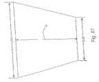
- the second wing 824is the retaining unit of the present embodiment.
- the second wing or retaining unit 824includes the upper portion 826 having a first width “a” and the lower portion 828 having a second width “b”.
- the second width “b”is larger than first width “a” due to the anatomical form or contour of the L4-L5 or L5-S1 laminae.
- the widths “a” and “b”would be increased in order to, as described hereinbelow, accommodate spinous processes and other anatomical forms or contours which are of different dimensions. Further, as appropriate, width “a” can be larger than width “b”.
- the implantcan include a universally-shaped distracting unit 802 with a plurality of retaining units 824 , with each of the retaining units having different widths “a” and “b”.
- the appropriately sized retaining unit 824 , width with the appropriate dimensions “a” and “b”can be selected to match to the anatomical form of the patient.
- FIG. 86depicts an assembled implant 800 positioned adjacent to upper and lower laminae 836 , 838 (which are shown in dotted lines) of the upper and lower vertebrae.
- the vertebrae 836 , 838are essentially below the implant 800 as shown in FIG. 86 .
- the fit of the implant between the spinous processescan be such that the wings do not touch the spinous processes, as shown in FIG. 86 , and be within the spirit and scope of the invention.
- the implant 800includes, as assembled, an upper saddle 844 and the lower saddle 846 .
- the upper saddle 844has an upper width identified by the dimension “UW”.
- the lower saddle 846has a lower width identified by the dimension “LW”.
- the upper widthis greater than the lower width.
- the “UW”can be smaller than the “LW” depending on the anatomical requirements.
- the height between the upper and lower saddles 844 , 846is identified by the letter “h”.
- the patientis preferably positioned on his side (arrow 841 points up from an operating table) and placed in a flexed (tucked) position in order to distract the upper and lower vertebrae.
- a small incisionis made on the midline of the spinous processes.
- the spinous processesare spread apart or distracted with a spreader.
- the incisionis spread downwardly toward the table, and the distracting unit 802 is preferably inserted upwardly between the spinous processes 840 and 842 in a manner that maintains the distraction of spinous processes.
- the distracting unit 802is urged upwardly until the distracting or bulbous end 808 and the slot 806 are visible on the other wide of the spinous process. Once this is visible, the incision is spread upwardly away from the table and the retaining unit or second wing 824 is inserted into the slot 806 and the screw 822 is used to secure the second wing in position. After this had occurred, the incisions can be closed.
- An alternative surgical approachrequires that small incisions be made on either side of the space located between the spinous processes.
- the spinous processesare spread apart or distracted using a spreader placed through the upper incision.
- the distracting unit 802is preferably inserted upwardly between the spinous processes 840 and 842 in a manner that urges the spinous processes apart.
- the distracting unit 802is urged upwardly until the distracting or bulbous end 808 and the slot 806 are visible through the second small incision in the patient's back. Once this is visible, the retaining unit or second wing 824 is inserted into the slot 806 and the screw 822 is used to secure the second wing in position. After this has occurred, the incisions can be closed.
- FIG. 80 ashows an alternative embodiment of the distracting unit 802 a .
- This distracting unit 802 ais similar to distracting unit 802 in FIG. 80 with the exception that the bulbous end 808 a is removable from the rest of the distracting body 804 a as it is screwed into the threaded bore 809 .
- the bulbous end 808 ais removed once the distracting unit 802 a is positioned in the patient in accordance with the description associated with FIG. 86 .
- the bulbous end 808 acan extend past the threaded bore 820 by about 1 cm in a preferred embodiment.
- FIGS. 88 , 89 , 90 and 91Another embodiment of the invention is shown in FIGS. 88 , 89 , 90 and 91 .
- the implantis identified by the number 900 .
- Other elements of implant 900 which are similar to implant 800are similarly numbered but in the 900 series.
- the distracting unitis identified by the number 902 and this is in parallel with the distracting unit 802 of the implant 800 .
- the distracting bodyis identified by the number 904 in parallel with the distracting body 804 of the implant 800 . Focusing on FIG. 90 , the distracting unit 902 is depicted in a perspective view.
- the distracting unitincludes slot 906 which is wider at the top than at the bottom.
- the wider upper portion of the slot 906which is wider than the second wing 924 ( FIG. 89 ), is used to allow the surgeon to easily place the second wing 924 into the slot 906 and allow the wedge-shaped slot 906 to guide the second wing 924 to its final resting position. As can be see in FIG. 91 , in the final resting position, the largest portion of the slot 906 is not completely filled by the second wing 924 .
- the end 908 of implant 900is different in that it is more pointed, having sides 909 and 911 which are provided at about 45° angles (other angles, such as by way of example only, from about 30° to about 60° are within the spirit of the invention), with a small flat tip 913 so that the body 904 can be more easily urged between the spinous processes.
- the distracting unit 902further includes a tongue-shaped recess 919 which extends from the slot 906 . Located in the tongue-shaped recess is a threaded bore 920 .
- a second wing 924includes a tongue 948 which extends substantially perpendicular there to and between the upper and lower portions 926 , 928 .
- the tab 948includes a bore 950 .
- a threaded set screw 922can be positioned through the bore 950 and engage the threaded bore 920 in order to secure the second wing or retaining unit 924 to the distracting unit 902 .
- the embodiment 900is implanted in the same manner as embodiment 800 previously described.
- the bore 922is substantially perpendicular to the distracting body 904 (and not provided at an acute angle thereto), the surgeon can even more easily secure the screw in place from a position directly behind the spinous processes.
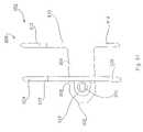
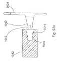
- FIGS. 92 , and 92 athe implant 1000 as can be seen in FIG. 92 a includes a central elongated body 1002 which has positioned at one end thereof a first wing 1004 .
- Wing 1004is similar to the first wing previously described with respect to the embodiment of FIG. 88 .
- Bolt 1006secures wing 1004 to body 1002 in this embodiment.
- Bolt 1006is received in a bore of the body 1002 which is along the longitudinal axis 1008 of body.
- the first unitis defined by the central body 1002 , the first wing 1004 , and the guide 1010 .
- the first wingcan be secured to the central body with a press fit and detent arrangement as seen in FIG. 93 c .
- the first winghas a protrusion 1040 extending preferably about perpendicularly from the first wing, with a flexible catch 1042 .
- the protrusion and flexible catchare press fit into a bore 1044 of the central body with the catch received in a detent 1046 .
- the first wingcan be designed as shown in FIG. 93 d with the protrusion directed substantially parallel to the first wing from a member that joins the first wing to the protrusion.
- the first wingis inserted into the body along the same direction as the second wing is inserted.
- guide 1010Positioned at the other end of the central body 1002 is a guide 1010 .
- guide 1010is essentially triangularly-shaped so as to be a pointed and arrow-shaped guide.
- guide 1010could be in the shape of a cone with lateral truncated sides along the longitudinal axis 1008 .
- Guide 1010includes a recess 1012 having a threaded bore 1014 .
- Recess 1012is for receiving a second wing 1032 as will be described hereinbelow.
- the guide 1010can be bulbous, cone-shaped, pointed, arrow-shaped, and the like, in order to assist in the insertion of the implant 1000 between adjacent spinous processes. It is advantageous that the insertion technique disturb as little of the bone and surrounding tissue or ligaments as possible in order to (1) reduce trauma to the site and facilitate early healing, and (2) not destabilize the normal anatomy. It is to be noted that with the present embodiment, there is no requirement to remove any of the bone of the spinous processes and depending on the anatomy of the patient, there may be no requirement to remove or sever ligaments and tissues immediately associated with the spinous processes.
- the implant 1000further includes a sleeve 1016 which fits around and is at least partially spaced from the central body 1002 .
- the implantmay be comprised of a bio-compatible material such as titanium
- the sleeveis comprised preferably of a super-elastic material which is by way of example only, a nickel titanium material (NiTi), which has properties which allow it to withstand repeated deflection without fatigue, while returning to its original shape.
- NiTinickel titanium material
- the sleevecould be made of other materials, such as for example titanium, but these materials do not have the advantages of a super-elastic material.
- FIG. 93 ais a cross-section through the implant 1000 depicting the central body 1002 and the sleeve 1016 .
- both the central body 1002 and the sleeve 1016are substantially cylindrical and oval or ecliptically-shaped.
- An oval or elliptical shapeallows more of the spinous process to be supported by the sleeve, thereby distributing the load between the bone and the sleeve more evenly. This reduces the possibility of fracture to the bone or bone resorption.
- an oval or elliptical shapeenhances the flexibility of the sleeve as the major axis of the sleeve, as described below, is parallel to the longitudinal direction of the spinous process.
- other shapessuch as round cross-sections can come within the spirit and scope of the invention.
- the central body 1002includes elongated grooves 1018 , along axis 1008 , which receives elongated spokes 1020 extending from the internal surface of the cylinder 1016 .
- both the cross-section of the central body and the sleevehave a major dimension along axis 1022 and a minor dimensional along axis 1024 ( FIG. 93 a ).
- the spokes 1020are along the major dimension so that along the minor dimension, the sleeve 1016 can have its maximum inflection relative to the central body 1002 .
- the central body along the minor dimension 1024can have multiple sizes and can, for example, be reduced in thickness in order to increase the ability of the sleeve 1016 to be deflected in the direction of the central body 1002 .
- the central body 1002can include the spokes 1020 and the sleeve 1016 can be designed to include the grooves 1018 in order to appropriately space the sleeve 1016 from the central body 1002 .
- the sleevecan have minor and major dimensions as follows:
- said sleevehas a cross-section with a major dimension and a minor dimension and said major dimension is greater than said minor dimension and less than about two times said minor dimension.
- said guidehas a cross-section which is adjacent to said sleeve with a guide major dimension about equal to said sleeve major dimension and a guide minor dimension about equal to said sleeve minor dimension. Further in said embodiment, said guide extends from said central body with a cross-section which reduces in size in a direction away from said central body.
- said guideis cone-shaped with a base located adjacent to said sleeve. Further, said guide has a base cross-section about the same as the oval cross-section of said sleeve.
- a major dimension of the sleevecorrespond with a major dimension of the central body and a minor dimension of the sleeve corresponds with a minor dimension of the central body.
- the major dimension of the sleeve 1016is substantially perpendicular to a major dimension of the first wing 1004 along longitudinal axis 1030 ( FIG. 92 a ). This is so that as discussed above, when the implant 1000 is properly positioned between the spinous processes, a major portion of the sleeve comes in contact with both the upper and lower spinous processes in order to distribute the load of the spinous processes on the sleeve 1016 during spinal column extension.
- the preferred material for the sleeve 1016is a super-elastic material and more preferably one comprised of an alloy of nickel and titanium. Such materials are available under the trademark Nitinol. Other super-elastic materials can be used as long as they are bio-compatible and have the same general characteristics of super-elastic materials.
- a preferred super-elastic materialis made up of the following composition of nickel, titanium, carbon, and other materials as follows:
- this composition of materialsis able to absorb about 8% recoverable strain.
- This materialcan be repeatably deflected toward the central body and returned to about its original shape without fatigue.
- this materialcan withstand the threshold stress with only a small amount of initial deforming strain and above the threshold stress exhibit substantial and about instantaneous deformation strain which is many times the small amount of initial deforming strain.
- FIG. 118shows a loading and unloading curve between stress and deformation strain for a typical type of super-elastic material as described above.
- the above super-elastic materialis selected to allow deformation of up to about, by way of example only, 8%, at about 20 lbs. to 50 lbs. force applied between a spinous processes. This would cause a sleeve to deflect toward the central body absorbing a substantial amount of the force of the spinous processes in extension.
- the sleevesare designed to absorb 20 lbs. to 100 lbs. before exhibiting the super-elastic effect (threshold stress level) described above.
- the sleevecan be designed for a preferable range of 20 lbs. to 500 lbs.
- the wall thickness of the sleeveis about 1 mm or 40/1000 of an inch (0.040 in.).
- the sleeveis designed to experience a combined 1 mm deflection.
- the combined 1 mm deflectionmeans that there is 1 ⁇ 2 mm of deflection at the top of the minor dimension and a 1 ⁇ 2 mm deflection at the bottom of the minor dimension. Both deflections are toward the central body.
- a 20 lb. loadcauses a 0.005 in. deflection and a 60 lb. load causes a 0.020 in. deflection (approximately 1 ⁇ 2 mm).
- a 100 lb. loadwould cause a deflection of about 0.04 in. or approximately 1 mm.
- the above preferred super-elastic materialmeans that the sleeve can be repeatedly deflected and returned to about its original shape without showing fatigue.
- the sleevecan withstand a threshold stress with a small amount of deforming strain and at about said threshold stress exhibit about substantially instantaneous deformation strain which is many times the small amount of the forming strain.
- such super-elastic qualitiesmean that the material experiences a plateau stress where the material supports a constant force (stress) over very large strain range as exhibited in FIG. 118 .
- bar stock of the super-elastic materialis machined into the appropriate form and then heat treated to a final temperature to set the shape of the material by increasing the temperature of the material to 932° Fahrenheit and holding that temperature for five (5) minutes and then quickly quenching the sleeve in water.
- the present nickel titanium super-elastic alloyis selected to have a transition temperature A f of about 59° Fahrenheit (15° C.). Generally for such devices the transition temperature can be between 15° C. to 65° C. (59° F. to 149 ° F.), and more preferably 10° C. to 40° C. (50° F. to 104° F.).
- the materialis maintained in the body above the transition temperature in order to exhibit optimal elasticity qualities.
- the sleevecan be fabricated by wire Electrical Discharge Machining (EDM) rather than machined. Additionally, the sleeve can be finished using a shot blast technique in order to increase the surface strength and elasticity of the sleeve.
- EDMElectrical Discharge Machining
- Second wing 1032as in several past embodiments includes a tab 1034 with a bore 1036 which aligns with the bore 1014 of the guide 1010 .
- the second wing 1032includes a cut-out 1038 which is sized to fit over the guide 1010 , with the tab 1034 resting in the recess 1012 of the guide 1010 .
- FIG. 94 aAn alternative configuration of the second wing 1032 is depicted in FIG. 94 a .
- the second wing 1032is held at acute angle with respect to the tab 1034 . This is different from the situation in the embodiment of FIGS. 94 and 95 where the second wing is substantially perpendicular to the tab.
- FIGS. 94 and 95For the embodiment of the second wing in FIG. 94 a , such embodiment will be utilized as appropriate depending on the shape of the spinous processes.
- elongated tab 1034has a plurality of closely positioned bores 1036 .
- the bores, so positioned,appear to form a scallop shape.
- Each individual scallop portion of the bore 1036can selectively hold the bolt in order to effectively position the second wing 1032 in three different positions relative to the first wing 1004 .
- the cut-out 1038( FIG. 95 a of this alternative embodiment) is enlarged over that of FIG. 95 as in a position closest to the first wing 1004 , the second wing 1032 is immediately adjacent and must conform to the shape of the sleeve 1016 .
- Implant 1050 of FIG. 97is similar to the implant 1000 in FIG. 92 with the major difference being that a second wing is not required.
- the implant 1050includes a central body as does implant 1000 .
- the central bodyis surrounded by a sleeve 1016 which extends between a first wing 1004 and a guide 1010 .
- the guide 1010 in this embodimentis substantially cone-shaped without any flats and with no bore as there is no need to receive a second wing.
- the sleeve and the central body as well as the first wing and guideact in a manner similar to those parts of the implant 1000 in FIG. 92 . It is to be understood a cross-section of this implant 1050 through sleeve 1016 can preferably be like FIG. 93 a .
- This particular embodimentwould be utilized in a situation where it was deemed impractical or unnecessary to use a second wing.
- This embodimenthas the significant advantages of the sleeve being comprised of super-elastic alloy materials as well as the guide being utilized to guide the implant between spinous processes while minimizing damage to the ligament and tissue structures found around the spinous processes.
- Implant 1060is depicted in FIG. 98 .
- This implantis similar to the implants 1000 of FIG. 92 and the implant 1050 of FIG. 97 , except that this implant does not have either first or second wings.
- Implant 1060includes a sleeve 1016 which surrounds a central body just as central body 1002 of implant 1000 in FIG. 93 . It is to be understood that a cross-section of this implant 1060 through sleeve 1016 can preferably be like FIG. 93 a .
- Implant 1060includes a guide 1010 which in this preferred embodiment is cone-shaped. Guide 1010 is located at one end of the central body. At the other end is a stop 1062 .
- Stop 1062is used to contain the other end of the sleeve 1016 relative to the central body.
- This embodimentis held together with a bolt such as bolt 1006 of FIG. 93 that is used for the immediate above two implants.
- a boltsuch as bolt 1006 of FIG. 93 that is used for the immediate above two implants.
- the implant 1060 of FIG. 98such a device would be appropriate where the anatomy between the spinous processes was such that it would be undesirable to use either a first or second wing.
- this embodimentaffords all the advantageous described hereinabove ( FIGS. 92 and 97 ) with respect to the guide and also with respect to the dynamics of the sleeve.
- FIGS. 99 and 100depict an implant system 1070 .
- Implant system 1070includes a sleeve 1072 which is similar to and has the advantageous of sleeve 1016 of the embodiment in FIG. 92 .
- Sleeve 1072does not, however, have any spokes.
- implant system 1070includes an insertion tool 1074 .
- Insertion tool 1074includes a guide 1076 which in a preferred embodiment is substantially cone-shaped. Guide 1076 guides the insertion of the sleeve 1072 and the insertion tool 1074 between adjacent spinous processes.
- the insertion tool 1074further includes a central body 1078 , a stop 1080 , and a handle 1082 .
- the guide 1076 at its basehas dimensions which are slightly less than the internal dimensions of the sleeve 1074 so that the sleeve can fit over the guide 1076 and rest against the stop 1080 .
- the tool 1074 with the guide 1076is used to separate tissues and ligaments and to urge the sleeve 1072 in the space between the spinous processes. Once positioned, the guide insertion tool 1074 can be removed leaving the sleeve 1072 in place. If desired, after the sleeve is positioned, position maintaining mechanisms such as springy wires 1084 made out of appropriate material such as the super-elastic alloys and other materials including titanium, can be inserted using a cannula through the center of the sleeve 1072 .
- the ends of the retaining wires 1084extend out of both ends of the sleeve 1072 , and due to this springy nature, bent at an angle with respect to the longitudinal axis of the sleeve 1072 . These wires help maintain the position of the sleeve relative to the spinous processes.
- FIG. 101Another embodiment of the invention can be seen in FIG. 101 which includes implant 1100 .
- Implant 1100has many similar features that are exhibited with respect to implant 1000 in FIG. 92 . Accordingly, elements with similar features and functions would be similarly numbered. Additionally, features that are different from implant 1100 can be, if desired, imported into and become a part of the implant 1000 of FIG. 92 .
- implant 1100includes a central body 1002 ( FIG. 102 ) with a first wing 1004 and a bolt 1006 which holds the first wing and the central body together.
- the central bodyis made in two portions.
- the first portion 1102is in the shape of a truncated cone with an oval or elliptical base and a second portion 1104 includes a cylindrical central portion with a distal end in the shape of a truncated cone 1103 with an oval or elliptical base.
- formed with the central bodyis the guide 1010 which has an oval or elliptical base.
- Bolt 1006is used to secure the first wing through the second portion 1104 with the first portion 1102 held in-between.
- the guide 1010in addition to including recess 1012 and bore 1014 includes a groove 1106 which receives a portion of the second wing 1032 .
- the sleeve 1016is preferably oval or elliptical in shape as can be seen in FIG. 102 a .
- the central bodycan be oval, elliptical or circular in cross-section, although other shapes are within the spirit and scope of the invention.
- the sleeve 1016held in position due to the fact that the truncated conical portion 1102 and the corresponding truncated conical portion 1103 each have a base that is elliptical or oval in shape.
- the sleeveis held in position so that preferably the major dimension of the elliptical sleeve is substantially perpendicular to the major dimension of the first wing.
- first wingis meant to be put beside the vertebrae so that the first wing is set at an angle other than perpendicular with respect to the vertebrae and that the sleeve may be held in a position so that the major dimension of the sleeve is at an angle other than perpendicular to the major dimension of the first wing and be within the spirit and scope of the invention.
- the major dimension of the sleevewould be preferably positioned so that it is essentially parallel to the length of the adjacent spinous processes. So configured, the elliptical or oval shape sleeve would bear and distribute the load more evenly over more of its surface.
- the sleeve in this embodimenthas all the characteristics and advantages described hereinabove with respect to the above-referenced super-elastic sleeves.
- the second wing as discussed abovecan come in a variety of shapes in order to provide for variations in the anatomical form of the spinous processes. Such shapes are depicted in FIGS. 103 , 104 , 105 , 106 , and 107 .
- the second wing 1032has a upper portion 1108 and a lower portion 1110 .
- the lower portionis thicker than the upper portion in order to accommodate the spinous process, where the lower spinous process is thinner than the upper spinous process.
- both the upper and lower portionsare enlarged over the upper and lower portions of FIG. 103 to accommodate both the upper and lower spinous processes being smaller. That is to say that the space between the upper and lower portions of the first and second wings are reduced due to the enlarged upper and lower portions of the second wing.
- FIGS. 106 and 107Alternative embodiments of second wings, as shown in FIGS. 104 and 105 , are depicted in FIGS. 106 and 107 .
- the second wing 1032accommodates the same anatomical shape and size of the spinous processes as does the second wing in FIGS. 104 and 105 respectively.
- substantial masseshave been removed from the wings.
- the upper and lower portions 1108 and 1110are essentially formed or bent in order to extend from the central portion 1112 of the second wing 1032 .
- the second wingmay not have to be used, depending on the anatomy of the spinal column of the body, and this embodiment still has the significant advantages attributable to the guide 1010 and the functionality of the sleeve 1016 .
- the implant 1120 as shown in FIGS. 108 and 109is similar to implant 1100 which is in turn similar to implant 1000 .
- Such similar detailshave already been described above and reference here is made to the unique orientation of the first and second wings 1122 and 1124 .
- These wingshave longitudinal axis 1126 and 1128 respectfully.
- the first and second wings 1122 , 1124have been rotated so that they both slope inwardly and if they were to continue out of the page of the drawing of FIG. 108 , they would meet to form an A-frame structure as is evident from the end view of FIG. 109 .
- the tab 1034is provided an acute angle to the remainder of the second wing 1124 .
- the groove 1018 formed in the implantis sloped in order to accept the second wing 1124 . Accordingly, this present implant 1120 is particularly suited for an application where the spinous process is wider adjacent to the vertebral body and then narrows in size at least some distance distally from the vertebral body. It is to be understood that a cross-section of this implant 1120 through sleeve 1016 can preferably be like FIG. 93 a.
- Implant 1150has features similar to those described with respect to FIG. 94 b.
- Implant 1150includes a central body 1152 with a first wing 1154 , where central body 1152 includes elongated groove 1156 which extends to the guide 1158 .
- a screw 1160is received in a threaded bore located in the elongated groove 1156 .
- the second wing 1162includes a central body 1164 which is substantially perpendicular to the second wing 1162 .
- the central body 1164includes a plurality of bores 1166 provided therein. These bores are formed adjacent to each other in order to define a plurality of scallops, each scallop capable of retaining bolt 1160 therein.
- the second wingincludes a cut-out 1168 such that with the central body 1164 of the second wing received in the groove 1156 of the central body associated with the first wing, the remainder of the second wing is received over the central body 1152 of the implant 1150 .
- the distance between the first and second wingscan be adjusted by selectively placing the bolt 1160 through one of the five specified bores defined by the scalloped plurality of bores 1166 .
- FIG. 112depicts the implant where the first and second wings are widest apart in order to accommodate spinous processes of greater thickness.
- FIG. 111shows the middle position between the first and second wings in order to accommodate average size spinous processes.
- the central body 1152is urged between spinous processes.
- the second wingis guided by the other sides of the spinous processes from a path which causes the plane of the second wing to move substantially parallel to the plane of the first wing until the central body 1164 associated with the second wing 1162 is received in the groove of 1156 of the central body 1152 associated with the first wing 1154 .
- the bolt 1160is positioned through aligned bores associated with the second wing 1162 and the central body 1152 in order to secure the second wing to the central body.
- embodiment 1150does not depict a sleeve such as sleeve 1016 , such a sleeve 1016 could be placed over body 1152 and be within the spirit of the invention.
- Implant 1200 of the inventionis depicted in FIGS. 119 a and 119 b .
- This implantincludes the first wing 1202 and sleeve 1204 and a guide 1206 .
- An alternative to this embodimentfurther includes, as required, second wing 1208 as depicted in FIGS. 120 a and 120 b.
- the first wing 1202includes a bore which receives a central body 1210 .
- the central bodyis pressed fit through the bore of the first wing although it is to be understood that other securing mechanisms such as through the use of threads and still other mechanisms can be used to accomplish this task.
- first and second pins 1212extend from the first wing 1202 , each along an axis which is substantially parallel to the longitudinal axis 1214 of the central body 1210 .
- the distal end 1216 of the central body 1210is threaded in order to be coupled to the guide 1206 .
- the guide 1206 in this particular embodimentis pointed in order to allow the implant to be inserted between, and if necessary distract, adjacent spinous processes.
- the guide 206includes a threaded bore 1218 which is designed to accept the threaded end 1216 of the central body 1210 in order to secure the guide to the central body and additionally for purposes of retaining the sleeve between the guide 1206 and the first wing 1202 .
- the sleeve 1204is preferably cylindrical, and oval or elliptical in shape in cross-section. It is to be understood that sleeve 1204 can have other shapes as described throughout the specification and be within the spirit and scope of the invention. In this particular embodiment, sleeve 1204 has at least one major diameter and one minor diameter in cross-section.
- Sleeve 1204includes a central bore 1220 which extends the length of sleeve 1204 and curve grooves 1222 which are formed about central bore 1220 and extend only part way into the body of the sleeve. In this particular embodiment, the curved grooves 1222 describe an arc of about 60°. It is to be understood that in other embodiment, this arc can be less than 60° and extend past 120°.
- the sleeve 1204is received over the central body 1210 of the implant 1200 and can rotate thereon about the longitudinal axis 1214 of the central body 1210 .
- the grooves 1222have received therein the pins 1212 that extend from the first wing 1202 . Accordingly, the pins inserted in the grooves 1222 assist in the positioning of the sleeve relative to the remainder of the implant 1200 . With the pins 1212 received in the curved grooves 1222 , the pins limit the extent of the rotation of the sleeve about the central body and relative to the first wing.
- the sleeveis free to rotate relative to the longitudinal axis of the central body 1210 and thus relative to the first wing 1202 of the embodiment shown in FIGS. 119 a and 119 b .
- the sleevecan rotate relative to a second wing 1208 , when the second wing is utilized in conjunction with the embodiment of FIGS. 119 a and 119 b .
- the pinslimit the rotation of the sleeve. In an alternative embodiment, the pins are eliminated so that the sleeve can rotate to any position relative to the first wing.
- the sleevecan be comprised of biologically acceptable material such as titanium. Additionally, it can be comprised of super-elastic material such as an alloy of nickel and titanium, much as described hereinabove with respect to other embodiments.
- the great advantage of the use of the sleeve 1204 as depicted in the embodiment of FIGS. 119 a and 119 bis that the sleeve can be rotated and repositioned with respect to the first wing 1202 , and/or the second wing 1208 should the second wing be used in the embodiment, in order to more optimally position the implant 1200 between spinous processes.
- the cortical bone or the outer shell of the spinous processesis stronger at an anterior position adjacent to the vertebral bodies of the vertebra that at a posterior position distally located from the vertebral bodies. Accordingly, there is some advantage of having the implant 1200 placed as close to the vertebral bodies as is possible.
- the sleeve 1204can be rotated relative to the wings, such as wing 1202 , so that the sleeve is optimally positioned between the spinous processes, and the wing 1202 is optimally positioned relative to the spinous processes. Without this capability, depending on the anatomical form of the bones, it is possible for the wings to become some what less than optimally positioned relative to the spinous processes.
- FIGS. 125 , 126 and 127depict three alternative embodiments of the invention as can be seen through a line parallel to line 124 - 124 of FIG. 119 b.
- the sleeve 1204is rotatable about central body 1210 .
- the sleeve 1204 designdoes not include the grooves 1222 as previously depicted in the embodiment shown in FIG. 123 a .
- the sleeveis completely free to rotate about the central body 1210 .
- FIG. 126An alternative embodiment is shown in FIG. 126 .
- the sleeve 1204is essentially a thin wall cylinder which is spaced from the central body 1210 .
- Sleeve 1204is free to move relative to central body 1210 .
- Sleeve 1204can rotate relative to central body 1210 .
- sleeve 1204can take a somewhat cocked or skewed position relative to central body 1210 .
- FIG. 127A further embodiment, it is shown in FIG. 127 .
- This embodimentis somewhat similar to the embodiment shown in FIG. 126 except that in this case, several pins project from the first wing in order to some what limit and restrict the motion of the sleeve 1204 .
- FIG. 127four pins are depicted. It is to be understood however that such an embodiment can include one, two, three, four or more pins and be within the spirit and scope of the invention. It is to be understood that if the embodiment is used with a second wing, that similar pins can extend from the second wing.
- the pinswould preferably be somewhat flexible so that they could snap into the inside of the sleeve 1204 as the second wing is inserted relative to the central body and secured in place.
- the sleeve 1204is free to rotate about the longitudinal axis of the central body 1210 and is somewhat restricted in this motion and its ability to become skewed relative to the longitudinal axis of the central body by the pins.
- FIG. 128is an advantageous alternative to that of FIG. 93 a .
- the central body 1002is similar to that as shown in FIG. 93 a .
- the sleeve 116is comprised of two sleeve portions 1016 a and 1016 b .
- the sleeve portionsare preferably formed from flat stock material which is substantially easier to form than having the sleeve formed or machined from solid bar stock material.
- a further advantage of the sleeve 1016if formed of super-elastic material, is that the sleeve can be formed in a manner which optimizes the super-elastic characteristics of such material in order to enhance its ability to repeatedly deflect under load.
- the sleeve portions 1016 a and 1016 bare somewhat C-shaped and then after being formed, are snapped into the grooves of the central body 1002 .
- FIG. 128An alternative embodiment of the invention is shown in FIG. 128 .
- This embodimentis most favorably used with the embodiment of FIGS. 119 a and 119 b .
- the sleeve 1204is designed to rotate about the central body 1210 .
- Sleeve 1204includes a central member 1230 which includes a bore that receives the central body 1210 .
- the central member 1230is rotatable about the central body 1210 of the implant 1200 .
- the central member 1230includes first and second grooves 1232 and 1234 . These grooves can receive C-shaped sleeve members 1204 a and 1204 b .
- These C-shaped sleeve membersare similar in construction and design to the C-shaped sleeve members shown above with respect to FIG.
- sleeve members 1204 a and 1204 bcan be formed from a single flat stock material such that one of the grooves 1232 and 1234 receives continuous piece of flat material which has been appropriately bent and the other grooves receives two ends of the sleeve.
- Embodiment 2000 of the supplemental spine fixation device of the inventionis depicted in FIG. 130 .
- This embodiment 2000includes a hub 2002 to which is adjustably secured a first hook member 2004 and a second hook member 2006 .
- First hook member 2004includes a hook 2008 which is more fully described hereinbelow, and a shaft 2010 extending therefrom.
- second hook member 2006includes a hook 2012 and a shaft 2014 extending therefrom.
- hook 2008is swivelly or pivotably mounted to shaft 2010 . It is to be understood that the description and functionality of first hook member 2004 applies equally well to that of second hook member 2006 .
- the shaft 2010 in this embodimentincludes a rack 2016 which can mate selectively with rack 2018 of hook member 2006 .
- These two racks 2016 and 2018interlock in a multitude of positions in order to adjust the position of first and second hook members 2004 and 2006 , relative to each other and relative to the hub 2002 .
- the shafts 2010 and 2014are positioned through bore 2020 in the hub 2002 , selectively interlocked together and are then lockingly positioned using a locking mechanism such as the screw 2022 .
- the hooks 2008 and 2012are designed and shaped to fit around spinous processes. Further, the hooks 2008 and 2012 are swivelly mounted to the shafts 2010 and 2014 in order to accommodate the various sizes, shapes, and positions of spinous processes of the human population.
- a shaft 2024Movably mounted to the hub 2002 is a shaft 2024 ( FIG. 131 ) and extending from the shaft 2024 is an inter-spinous process guide 2026 .
- the shaft 2024 at a proximal endincludes a crossbar or tab 2028 which is slidingly or movingly received in a slot 2030 of the hub 2002 . Once the tab 2028 is received in the slot 2030 , the slot can be pinched off or slightly deformed at its open end using a punch or other mechanism in order to prevent the tab 2028 , and thus the shaft 2024 and the guide 2026 from being removed from the hub 2002 .
- the shaft and also the guide 2026 extending from the distal end of the shaft 2024are free to move relative to the hub and also relative to the first hook member 2004 and the second hook member 2006 .
- This movement, as well as the ability of the hooks 2008 and 2012 to swivel on the shafts 2010 and 2014allow the embodiment 2000 to conform to the spinous process anatomy.
- Spacer 2032Movably mounted on the shaft 2024 is a spacer or sleeve 2032 .
- Spacer 2032includes a central bore 2034 through which the shaft 2024 extends. The spacer 2032 is thus able to rotate about the shaft 2034 .
- the spacer 2032is cylindrical and in this particular embodiment is oval or elliptical in shape.
- the base of the guide 2026is also somewhat elliptical in shape in order to make a smooth transition between the guide 2026 and the spacer 2032 as the guide and spacer are inserted between the spinous processes in order to distract apart the spinous processes during the insertion process. When the spacer 2032 is fully inserted between the spinous processes, the spacer 2032 extends through the sagittal plane defined by the adjacent spinous processes.
- the spacer 2032As the spacer 2032 is rotatable on the shaft 2024 , and as the spacer 2032 is elliptically shaped, it can be inserted in one position and then as the entire embodiment 2000 is positioned to the final securing position, the spacer 2032 can rotate about the shaft 2024 to accommodate the shape of the space between the spinous processes as the spacer is moved from a posterior position to an anterior position.
- the spacer 2032can include a second alternative spacer embodiment 2036 ( FIG. 131 a ) in substitution for the spacer 2032 .
- Spacer 2036includes an elongated slot 2038 into which the shaft 2024 can be received.
- Elongated slot 2038not only allows the spacer 2036 to rotate about the shaft 2024 , it also allows it to translate relative to shaft 2024 . Such translation in this embodiment is substantially perpendicular to the shaft, in any direction to which the spacer 2036 is rotated.
- the degrees of freedom which accommodate the anatomical shape of the spinous processes and the space therebetween, including the ligaments and tissues associated therewithinclude (1) the ability of the hooks 2004 , 2006 to swivel on the shafts, (2) the ability of the hooks 2004 , 2006 to move relative to the hub 2002 and be locked to the hub, (3) the ability of the shaft 2024 to move in the slot 2030 of the hub, and (4) finally the ability of the spacer 2036 to both rotate and translate on the shaft 2024 .
- the implant 2000can be comprised of stainless steel, titanium or other biologically acceptable materials.
- the shape of the lead-in plugcan be cone shaped, pyramid shaped, and other shapes with a small lead-in cross-section expanding into a larger cross-section which is similar to the cross-section of the spacer 2032 , in order to gradually distract apart the spinous processes to a sufficient distance so that the spacer 2032 or the spacer 2036 can conveniently fit between the spinous processes.
- the spaceras shown in the other embodiments, can include a spacer made of stainless steel or titanium, or of a super-elastic material or of a silicone.
- the spacerbesides being cylindrical can, from parallel planar end 2040 to parallel planar end 2042 , be saddle-shaped along surface 2041 so that the ends are high and the center portions are low in order to more fully accommodate the shape of the spinous processes and also to spread the load across a broader contact surface between the spinous processes and the spacer.
- the spacer 2032could have a shape such as the saddle shape defined by the mated together components of the embodiment of FIG. 16 .
- the dimensions of this embodiment as applied to the guide 2006 and the spacer 2032can be acquired from other embodiments presented herein.
- the shape of the guide 2026 and the spacer 2032is such that for purposes of insertion between spinous processes, the spinous processes to do not need to be altered or cut away in any manner in order to accommodate this implant. Further, the associated ligaments do not need to be cut away and there would be very little or no damage to the other adjacent and surrounding tissues. Similarly, the hook members 2004 , 2006 , are appropriately shaped and also pivotable so that alteration of the spinous process is not required.
- the design of the hook members 2004 and 2006are more fully depicted and described. As indicated above, the description will be made with respect to first hook member 2004 . This description applies equally to second hook member 2006 .
- the first hook member 2004includes a shaft 2010 which is received in a bore 2044 of the hook 2008 . This bore receives a rounded ball end 2046 seated against a somewhat circular seat 2048 .
- a screw 2050( FIG. 135 f ) is received in the bore 2044 in order to retain the rounded ball end 2046 .
- the other end of the bore 2044 , end 2052as can be seen in FIG.
- 135 fis oval or elliptical in shape. This allows the hook 2008 to swivel side to side on the shaft 2010 in order to accommodate the spinous process while somewhat restricting the back and forth rocking of the hook 2008 relative to the shaft 2010 .
- This freedom of motioncan be seen in FIG. 136 with respect to the upper spinous processes 2054 .
- the hookcan swivel side to side in order to accommodate the shape of the upper spinous processes 2054 .
- the lower hook 2006additionally can move in order to accommodate the lower spinous processes 2056 .
- the hook 2008can swivel about 15° on either side of a central longitudinal axis of the shaft 2010 .
- the hookincludes a convex inner surface 2058 in order to accommodate the varying surface shape of the spinous processes, and in order to even out the load transferred between the hook and the spinous processes.
- the embodiment 2000can be implanted in a number of methods, preferably, once a spine fixation device is implanted between the vertebral bodies.
- a spine fixation deviceis implanted between the vertebral bodies.
- the hub, spacer, and guideare inserted with the guide and spacer inserted between the spinous processes.
- a first hook member and then a second hook memberis secured about the respective spinous processes.
- the shafts of the hook membersare then inserted through the bore of the hub 2002 until the spinous processes are brought tight against the spacer.
- the hooksare appropriately positioned on the spinous processes as depicted in FIG. 136 .
- the securing mechanism 2022is tightened in order to lock the hooks in place and to secure the spinous processes in a rigid manner relative to each other and relative to the distracting spacer 2032 .
- the spinous ligamentscan hold the spinous processes tightly against the spacer and the hooks can be moved and locked into tight contact with the spinous processes.
- the hookscan be inserted first through the incision and then the guide, spacer and hub can be inserted. Once this is accomplished the hooks can be mated to the hub.
- the physiciancan insert the shaft 2024 on which the spacer 2032 is mounted into the slot 2030 of the hub 2002 and can close off the slot with a securing screw in order to retain shaft 2024 .
- This processis in contrast to the shaft being secured in the slot during the manufacturing process.
- the securing screwwould be similar to securing screw 2022 and would be placed in a bore made at the top of slot 2030 .
- the physiciancould accordingly insert the tab 2028 of the shaft 2024 in the slot 2030 , and then secure the tab in place with the securing screw.
- the device 2000could be inserted through a larger incision, with device 2000 fully assembled. Once inserted the screw 2022 could be loosened so that the hook members could be positioned around spinous processes at about the same time that the guide and spacer are inserted between the spinous processes. Once this is accomplished, the spinous processes could be drawn down tightly around the spacer, with the hooks tightly around the spinous processes and secured firmly into the hub 2002 with the securing screw 2022 .
- the device 2000can address the adjacent spinous processes from one side of the spinous processes and not require exposure of both sides of the spinous processes and thus the procedure is less traumatic to the surgical site.
- Still an alternate insertion methodwould be to insert the device fully assembled with the hook rotated at 90° to the final position shown in FIG. 130 .
- the hookscould be rotated to the position shown in FIG. 130 .
- the guide and spacercould be inserted between the spinous processes, as the hooks are positioned about the spinous processes.
- the hooksare then drawn together, causing the spinous processes to be held firmly against the spacer. Once this is accomplished the screw 2022 can be securely fastened to the hub 2002 .
- this embodiment as fully described abovecan be used as a supplemental fixation or augmentation device for the lumbar level fusion of the L4/L5 vertebrae and above vertebrae, and also for the L5/S1 and below vertebrae.
- this device 2000can be used with respect to fusion of any of the vertebrae up and down the spinous processes.
- FIGS. 137-140Another embodiment 2100 of the invention can be seen in FIGS. 137-140 . Components and features of this embodiment 2100 which are similar to components and features of the embodiment 2000 have similarly least significant digits.
- the hub for embodiment 2100would be 2102 .
- the main difference between the embodiment 2100 and the previously described embodiment 2000is directed to the hub 2102 and the shafts 2110 and 2114 .
- the shafts 2110 , 2114are substantially rectangular in cross-sections as opposed to semi-circular as in the previous embodiment of FIG. 130 .
- shaft 2110is substantially rectangular in cross-section and include rack or teeth 2116 .
- Shaft 2114is shaped as a fork with two tines 2115 and 2117 .
- the two tineshave rack or teeth 2118 .
- the shaft 2110 of the first hook member 2104slides between the two tines 2115 and 2117 .
- the top cap 2103(which is shown both from the top side ( FIG. 138 ) and from the bottom side ( FIG. 138 b )) can be placed over the hub 2102 .
- the teeth or rack 2105 on the bottom side of the cap 2103mesh with the teeth or rack 2116 and 2115 , 2117 of the first and second hook members.
- the screw 2122can be inserted through the indicated bore so that the cap 2103 can tighten down on the hub 2102 , locking the shafts 2110 and 2114 of the first and second hook members in place.
- FIGS. 141-143Another embodiment of the invention is depicted in FIGS. 141-143 .
- This embodimentis similar to the other embodiments 2000 and 2100 .
- This embodimentis numbered 2200 .
- Similar elements, features, methods and aspectshave similar numerical designations with respect to the lowest two significant digits.
- the hub of embodiment 2200is identified as hub 2202 .
- the hubhas rigidly affixed thereto shaft 2224 .
- shaft 2224does not slide in a slot as happens with respect to the prior two embodiments 200 and 2100 .
- Shaft 2224can be screwed into hub 2202 or integrally formed with hub 2202 .
- the guide 2226can be integrally formed with the shaft 2224 or in other manners fastened to the shaft 2224 as with a thread mechanism.
- the shaft 2224is integrally formed with the hub 2202 and the shaft 2224 includes a threaded extension 2225 onto which is screwed the guide 2226 .
- the sleeve or spacer 2236includes the elongated slot 2238 in order to provide for freedom of movement between the sleeve or spacer 2236 , the hub 2202 , and the first and second hook members 2204 and 2206 .
- the shaft 2210 and 2214are similar to those depicted with respect to the embodiment 2000 .
- eachhas a rack or teeth which mate with the other.
- Shafts 2210 and 2214are inserted through the semi-circular bore 2220 of the hub 2202 , and then the cap 2203 is mated on top of the hub 2202 .
- the capincludes a semi-circular bore 2207 which is positioned over the upper shaft 2210 .
- Both bores 2207 and 2220include ribs, teeth, or threads that run along the length of the bores. These ribs, teeth, or threads are urged against the shafts in order to assist in locking the shafts in place.
- the ribs, teeth, or threads of the borescan be across the length of the bores.
- the shafts 2210 and 2214can have teeth, ribs, or threads that are positioned all about the shafts so that the shafts can lock to each other, and so that the teeth, racks or threads on the bores can lock the shafts in place.
- the degrees of freedomare attributable to (1) the slot 2238 in the spacer 2236 , (2) the shafts 2210 and 2224 which can be positioned relative to each other to position the hooks 2204 and 2206 relative to the hub, and accordingly relative to the spacer, and (3) the ability of the hooks 2204 and 2206 to swivel or pivot.
- a preferred method of insertion of this embodiment 2200 into a patientis as follows. Initially through a small incision the guide, spacer and hub are inserted so that the guide is positioned between and distracts apart adjacent spinous processes, allowing the spacer to come between the spinous processes.
- the spacer and guidecan be moved in a posterior to anterior direction, and the spacer is able to rotate and translate in order to accommodate such movement.
- the first and second hook membersare positioned through the incision and around upper and lower spinous processes. Once that is accomplished, the spinous processes are urged towards each other and about the spacer, if this is not already the condition caused by the insertion of the spacer in order to distract the spinous processes. Then the racks of the shafts are meshed together, and the cap is placed upon the hub in order to secure the hooks firmly to the hub and thus to secure the spinous processes rigidly in position about the spinous processes.
- FIG. 144A further embodiment 2300 of the invention is depicted in FIG. 144 .
- the hub 2302 of this embodimentis depicted.
- This hubcould be used, for example, with the embodiment shown in FIG. 141 and similar components are similarly numbered.
- the hub 2302includes an integral shaft 2324 with a threaded end 2325 which can accept a guide such as guide 2226 of FIG. 141 .
- this hub 2203does not have a cap.
- hub 2302includes an open bore 2320 which is shaped in order to receive shafts 2310 and 2314 , which have mating notches or teeth. Bore 2320 has a portion 2321 which is circular and which receives the mated shaft 2310 , 2324 .
- a screw 2322is received in the threaded bore 2323 in order to lockingly position the mated shafts 2310 , 2324 .
- this embodimenthas an open bore 2320 and no cap, mating of the shafts 2310 , 2314 to the open bore 2320 of the hub 2302 can be done quickly and efficiently.
- FIG. 145shows a hub 2402 of an embodiment 2400 .
- This hub 2402is similar to hub 2302 , with the open bore 2420 having a shape which is different from the shape of bore 2320 .
- bore 2420includes a flat 2421 and a circular portion 2423 .
- the shafts 2410 and 2414 when mated togetherwould register in this open bore 2420 .
- shaft 2414has a flat which mates to flat 2421 and the combined shafts 2410 and 2424 have a circular portion which would mate to the circular portion 2423 of the bore 2420 .
- hub 2202would function similarly to hub 2302 .
- FIGS. 146 a , 146 b , and 146 cdepict a hub arrangement 2502 of an embodiment 2500 of the invention.
- hub 2502has two components 2511 and 2513 .
- Component 2511includes an open bore 2520 which is specially shaped in order to register shafts 2510 , 2514 of the first and second hook members.
- shaft 2510is semi-circular in cross-section while shaft 2514 is triangular-shaped in cross-section. The triangular shape of shaft 2514 mates with the corner 2525 of the open bore 2520 .
- the term open borerefers to 2520 and also to bores 2320 and 2420 in FIGS.
- the shafts 2510 , 2514are inserted as shown FIG. 146 c , a screw 2522 can be tightened through a bore of the hub 2502 , locking the shafts in place.
- the first portion 2511 of the hub 2502can be mated into the second portion 2513 of the hub 2502 .
- the second portion of the hub 2513includes a slot 2515 into which can be slid or snapped into the first portion 2511 .
- the first portion 2511includes tangs 2517 and 2519 which fit under lips 2521 , 2523 respectively as the first portion 2511 of the hub 2502 is slid or alternatively snapped into engagement with the second portion 2513 .
- a locking cam 2527is turned in order to cause a cam member to be urged against this portion 2511 of the hub in order to lock 2511 to the second portion 2513 .
- the act of sliding or snapping hub portion 2511 into hub portion 2513can be sufficient to lock portion 2511 into portion 2513 .
- This embodimentfurther includes spacer 2536 and cone shaped guide 2526 .
- one insertion methodologycan be to insert the second hub portion 2513 with the guide 2526 into the position between the spinous processes. After this is accomplished, the hook members can be positioned about the spinous processes and locked into the first hub portion 2511 . Then the first hub portion 2511 could be slid or snapped into engagement with the second hub portion 2513 . Following that, the cam 2527 can be turned in order to secure the first hub portion 2511 to the second hub portion 2513 .
- FIGS. 147 a and 147 bdepict another embodiment 2600 of the invention.
- This embodiment 2600includes a hub 2602 and a rack and pinion arrangement.
- the rack and pinion arrangementincludes first and second pinions 2660 and 2662 . These pinions engage shafts 2610 and 2614 respectively.
- these shafts 2610 and 2614have rounded ends to which the hook is secured as depicted in, for example, FIG. 131 .
- these hookshave been left off of FIGS. 147 a , 147 b .
- the position of the shafts 2610 and 2614can be adjusted relative to the hub. Once the shafts 2610 , 2614 are appropriately positioned the pinions can be locked in position, locking the shafts in position. Pinions can be locked in position by tightening down screws such as screw 2664 against the pinion 2660 . A similar screw, not shown, would tighten down pinion 2662 .
- FIGS. 148 a and 148 bAnother embodiment of the invention, embodiment 2700 is depicted in FIGS. 148 a and 148 b .
- a bevel gear arrangement 2770is contained in the hub 2702 .
- Bevel gear arrangement 2770includes a first bevel gear 2772 and a second bevel gear 2774 .
- Bevel gear 2772has a shaft 2776 extending therefrom with a slot 2778 . Slot 2778 can receive a tool for turning the bevel gear 2772 .
- Bevel gear 2774is mated to a threaded shaft 2710 of the hook member 2704 . In this particular embodiment, the hook is not shown as is the case for the embodiment of FIGS. 147 a and 147 b .
- the bevel gear 2772is turned, it turns bevel gear 2774 .
- bevel gear 2774causes the threaded shaft 2714 to retreat into or extend out of the center of the other shaft 2710 .
- the bevel gear 2772can be used to turn bevel gear 2774 in order to draw the hook member 2706 toward the hub 2702 , tightening the hook members about the spinous processes.
- a shaft 2724extends therefrom in order to receive a spacer and a guide in the same manner that, for example, the embodiment of FIG. 144 receives a spacer and a guide.
- FIGS. 149 a and 149 bdepict embodiment 2800 of the invention.
- Embodiment 2800includes a hub 2802 which houses a turnbuckle arrangement 2880 which is actuated by a worm gear drive 2882 .
- Turnbuckle 2880receives the threaded shaft 2810 and 2814 of the hook members 2804 , 2806 respectively. As with the past embodiments, the actual hooks of these hook members are not depicted in order to simplify the drawing.
- the turnbuckle 2880By turning the turnbuckle 2880 , the threaded shafts 2810 , 2814 are either drawn into or urged out of the turnbuckle.
- the turnbuckleturns, causing the hook members to extend out of or be urged into the hub 2802 .
- Extending from the hubis a shaft 2824 with a threaded end 2825 .
- a spacercan be placed on the shaft 2824 and a guide can be placed on the threaded end 2825 .
- the preferred method of inserting this embodimentis to insert the embodiment as a whole, placing the guide and spacer between the spinous processes.
- the hookswould be initially rotated 90° from their final orientation. Once inserted adjacent to the spinous processes, the hooks would be rotated by 90° and the spacer and the hooks would be further urged into contact with the spinous processes. Once this has occurred, the turnbuckle would be turned in order to tighten the hooks about the spinous processes.
- FIG. 150Another embodiment 2900 of the invention is depicted in FIG. 150 .
- This embodimentis similar to several of the other embodiments and, in particular, to the embodiment shown in FIG. 130 . Accordingly, similar elements will have similar least significant numbers.
- the hubis designated 2902 .
- the hubis comprised of two components, the first hub component 2911 and the second hub component 2913 . This is somewhat similar to the hub components shown in FIG. 146 b.
- the two hook membersare secured to the first hub component 2911 in much the same manner as the hook members of FIG. 130 are secured to the hub in FIG. 130 .
- the hub 2902is divided into first hub component 2911 and second hub component 2913 in order to add flexibility in the positioning of the guide and spacer fitted to second hub component 2913 with respect to the first and second hook members 2904 and 2906 which are secured to the first hub component 2911 .
- the spacer 2936 and the guide 2926can be moved relative to the first and second hook members 2904 and 2906 by selectively positioning the second hub component 2913 relative to the first hub component 2911 . This can be accomplished by aligning the bore 2980 over one of the plurality of bores 2982 positioned through the first hub component 2911 .
- a threaded screw 2984can be inserted through smooth bore 2980 and engage one of the threaded bores 2982 in order to secure the second hub component 2913 to the first hub component 2911 , thus positioning the sleeve or spacer 2936 in a desired location relative to the first and second hook members.
- Embodiment 3000is meant for a double level spinous process fixation. That is to say that three spinous processes are engaged and rigidly fixed together. Such a situation would occur, for example, when there is a double level primary fusion. That is, three adjacent vertebral bodies are all fused together. In such a situation a double level supplemental spine fixation device 3000 would be used.
- This embodiment 3000could be designed using any of the other embodiments depicted heretofore.
- Embodiment 3000is in this particular instance modeled after the embodiment 2000 shown in FIG. 141 . Accordingly, the elements that are similar to FIG. 141 have similarly least significant digits.
- the hub caps, sleeves, hook members, spacers, and guidesare similarly numbered.
- two hubs, two spacers, and two guidesare required as the first guide 3026 and the spacer 3036 would be inserted between first and second spinous processes, while the second guide 3026 and spacer 3036 would be inserted between the second and third spinous processes.
- the hook members 2004 and 2006would hook about the first spinous process and the third spinous process respectively.
- a preferred method of insertion of the device relative to three spinous processeswould be to insert the guides and spacer between the first and second, and then the second and third spinous processes in order to distract apart the first and second spinous processes and also to distract apart the second and third spinous processes.
- the first hook memberwould be placed about the first spinous process and the second hook member would be placed about the third spinous process.
- the shafts of the hook memberswould be inserted in the respective hubs 3002 . In this situation, the shafts are both up-facing racks or teeth as shown in FIG. 151 .
- a linking shaft 3039has downwardly facing racks or teeth. Thus the upwardly facing rack or teeth of the first hook member 2004 would be laid in the upper hub 3002 with the teeth facing up.
- the teeth of the member 3039 facing downwould engage the rack or teeth of the first hook 2004 .
- the capwill be placed over the hub and the screw inserted in order to rigidly secure the hook member and the shaft 3039 relative to the upper hub 3002 .
- the shaft of the second hook 2006would be positioned in the lower hub 3002 .
- the rack of shaft 3039would mesh and lock with the rack of the shaft of the second hook member 2006 .
- the cap 3203would be placed over the hub and the screw would be inserted through the cap into the hub in order to secure the shaft 3039 and the second member 2006 relative to the lower hub.
- FIG. 152An alternate embodiment 3100 of the supplemental spine fixation device of the invention is depicted in FIG. 152 .
- This embodiment 3100includes a hub 3102 to which is adjustably secured a first hook member 3104 and second hook member 3106 .
- First hook member 3104includes a hook 3108 which is more fully described herein below, and a shaft 3110 extending therefrom.
- second hook member 3106includes a second hook 3112 and shaft 3114 extending therefrom. Shaft 3110 and 3114 are assembled together in a manner as will be described hereinbelow.
- hook 3108is swivelly or pivotally mounted to shaft 3110 . It is to be understood that the description and functionality of the first hook member 3108 applies equally well to that of the second hook member 3106 .
- the shaft 3110onto which hook 3108 is mounted in this embodiment, is received inside of the shaft 3114 .
- Shaft 3110can extend from shaft 3114 in a telescoping or sliding manner relative to shaft 3114 or alternatively shaft 3110 can be threaded into shaft 3114 and the rotation of shaft 3110 would allow it to extend from or be retracted into shaft 3114 .
- Shafts 3110 and 3114are received in a bore 3120 of the hub 3102 . In this particular embodiment shaft 3114 can be press fit or otherwise secured in bore 3120 . Shaft 3110 is thus free to move relative to the hub 3102 and the shaft 3114 , until the hub 3102 is assembled, locking shaft 3110 into position in this particular embodiment. This locking arrangement will be discussed more fully below.
- the hooks 3108 and 3112are designed and shaped to fit to spinous processes. Further the hooks 3108 and 3112 are swivelly mounted to the shafts 3110 and 3114 , respectively, in order to accommodate the various sizes, shapes, and positions of the spinous processes of the human population.
- a shaft 3124Swivelly mounted to the hub 3102 is a shaft 3124 , and extending from the shaft 3124 is an inner-spinous process guide, or lead-in nose, or tissue expander 3126 .
- the shaft 3124 at its proximal endincludes a ball 3125 , which is received in socket 3127 which is formed by the two portions of the hub 3102 .
- the shaft 3124is pivotable with respect to the hub 3102 .
- the tissue expand 3126has some freedom of movement with respect to the hub 3102 .
- the other end of the shaft 3124( FIG. 154 a ) also includes a ball 3129 which fits into a socket arrangement 3131 created in the guide or tissue expander 3126 .
- This arrangementallows the guide or tissue expander 3126 to pivot with respect to the shaft 3124 . Accordingly the shaft 3124 is free to pivot relative to the hub and the guide or tissue expander 3126 is free to pivot relative to shaft 3124 .
- This movement, as well as the ability of hooks 3108 and 3112 to swivel on the shaft 3110 and 3114 , and the ability of the shaft to be positioned relative to each otherallows the embodiment 3100 to conform to the spinous process anatomy.
- a sleeve or spacer 3132is pivotally mounted on the shaft 3124 along with the guide 3126 .
- the sleeve spacer 3132is free to rotate relative to the guide 3126 .
- Spacer 3132includes a central bore 3134 in which the shaft 3124 extends. The spacer 3132 as well as guide 3136 are thus able to pivot and rotate about the shaft 3124 .
- the spacer 3132 in this embodimentis cylindrical and in this particular embodiment is oval or elliptical in shape. For such shapes, the spacer can have minor diameters of 6 mm, 8 mm, 10 mm, and 12 mm. Smaller and larger diameters are within the spirit and scope of the invention.
- the spacercan be egg shaped as more fully described below.
- the base of the guide 3126is somewhat elliptical in shape in order to make a smooth transition between the guide 3126 and the spacer 3132 as the guide and spacer are inserted between the spinous processes in order to distract apart the spinous processes.
- the spacer 3132As the guide 3126 and the spacer 3132 are rotatable and pivotable on the shaft 3124 , and as the spacer 3132 is elliptically shaped, it can be inserted into one position and then as the entire embodiment 3100 is positioned to the final securing position, the spacer 3132 can be rotated about the shaft 3124 and pivoted relative thereto in order to accommodate the shape of the space between the spinous processes as the spacer is moved generally from a posturing position to an anterior position closer to the spine.
- the central bore 3134 of the spacer 3132has a first end 3133 which is enlarged and in this particular embodiment substantially elliptical in shape.
- the second end 3135is smaller.
- FIGS. 154 a and 154 bwhere in phantom various positions of the shaft 3124 are depicted demonstrating the pivotability of the guide 3124 and the sleeve 3132 relative to the hub 3102 .
- the shaft 3124is inserted into the small end 3135 of the sleeve 3132 .
- a retainer 3137is inserted relative to the ball 3129 of the shaft 3124 .
- the lead-in nose or tissue expander 3126is then inserted over the small end 3139 of the sleeve 3132 and pin 3141 is inserted into aligned slots in the guide 3126 and the sleeve 3132 in order to assemble together guide 3126 , the retainer 3137 and the sleeve 3132 about the ball 3129 of the shaft 3124 to create a ball and socket arrangement, whereby the guide 3126 and sleeve 3132 are pivotable and rotatable about the ball 3129 .
- a sleeve or spacer 3132is pivotally mounted on the shaft 3124 along with the guide 3126 .
- the sleeve spacer 3132is free to rotate relative to the guide 3126 .
- Spacer 3132includes a central bore 3134 in which the shaft 3124 extends. The spacer 3132 as well as guide 3136 are thus able to pivot and rotate about the shaft 3124 .
- the spacer 3132 in this embodimentis cylindrical and in this particular embodiment is oval or elliptical in shape. For such shapes, the spacer can have minor diameters of 6 mm, 8 mm, 10 mm, and 12 mm. Smaller and larger diameters are within the spirit and scope of the invention.
- the spacercan be egg shaped as more fully described below.
- the base of the guide 3126is somewhat elliptical in shape in order to make a smooth transition between the guide 3126 and the spacer 3132 as the guide and spacer are inserted between the spinous processes in order to distract apart the spinous processes.
- the spacer 3132As the guide 3126 and the spacer 3132 are rotatable and pivotable on the shaft 3124 , and as the spacer 3132 is elliptically shaped, it can be inserted into one position and then as the entire embodiment 3100 is positioned to the final securing position, the spacer 3132 can be rotated about the shaft 3124 and pivoted relative thereto in order to accommodate the shape of the space between the spinous processes as the spacer is moved generally from a posturing position to an anterior position closer to the spine. When the spacer 3132 is fully inserted between the spinous processes, the spacer 3132 extends through the sagittal plane defined by the adjacent spinous processes.
- the embodiment as shown in FIG. 154 ccould be modified to so that the small end 3139 of the spacer 3132 or of the spacer 3136 is severed from the remainder of the spacer 3132 , 3136 and pinned by itself to the guide 3126 in order to capture the ball of the shaft.
- the remainder of the spacer 3132 , 3136could rotate free of guide 3126 .
- the implant 3100can be comprised of stainless steel, titanium, or other biologically acceptable materials.
- the shape of the lead in plugcan be cone shaped, pyramid shaped and other shapes with a small lead in cross-section expanding into a larger cross-section which is similar to the cross-section of the spacer 3132 , in order to gradually distract apart the spinous processes to a sufficient distance so that the spacer 3132 or the spacer 3136 can conveniently fit between the spinous processes.
- the spaceras shown in the other embodiments, can include a spacer made of stainless steel or titanium or of a super-elastic material or of a silicone.
- the spacerbesides being cylindrical, can be saddle-shaped along the surface which engages the spinous processes so that the high edges and the lower central portions can more fully accommodate the shape of the spinous process.
- the spacer 3132 or 3136could have a shape such as the saddle shape defined by the mated together components of the embodiment of FIGS. 16 .
- dimensions of this embodiment as applied to the guide 3106 and the spacer 3132can be acquired from other embodiments presented herein.
- the guides and spacerscan have multiple shapes with the small diameter of the elliptical shape being on the order of 6 mm, 8 mm, 10 mm, 12 mm and 14 mm.
- the shape of the guide 3126 and the spacer 3132 or the spacer 3136is such that for purposes of insertion between the spinous processes, the spinous processes do not need to be altered or cut away in any manner in order to accommodate this implant. Further, the associated ligaments do not need to be cut away and there would be very little or no damage to the other adjacent and surrounding tissues.
- the hook members 3104 and 3106are appropriately shaped, as described below and are also pivotable so that alterations of the spinous processes is not required.
- the first hook 3108includes a bore 3144 into which the shaft 3110 is received.
- the shafthas a rounded end which has a bore provided therethrough. This bore mates with the bore 3145 associated with the bore 3144 of the hook 3108 .
- a pin or screwcan be inserted in order to lock the hook 3108 onto the shaft 3110 .
- the lower end 3147 of the bore 3144is oval or ob-round in shape allowing for the shaft to be pivotally received in the bore.
- the hook 3108is pivotable with respect to the end of the shaft 3110 .
- the hookthus can pivot in order to accommodate the shape of the spinous process.
- the lead in nose or guide or tissue expander 3150 of the hook 3108is pointed as can be additionally seen in FIGS. 155 d and 155 e . This allows the guide 3150 to be easily inserted between spinous processes and spread the tissue so that the concave recess 3152 can be received over the spinous process.
- the hookis then locked on the spinous process in order to retain the hook 3108 in place adjacent to the spinous process.
- the recess 3152has a cross-section which is convex in shape in order to accommodate the various surface shapes of the spinous process and in order to even out the load transfer between the hook and the spinous process.
- this noseis essentially shaped in the form of a pyramid with all of its sides rounded and curved. This allows the nose 3150 to easily be inserted over and past the spinous process, until the concave recess 3152 rests over the spinous process with the hook element 3154 caught by the spinous process in order to retain the hook 3108 in place.
- the hub 3102is comprised of two portions.
- the lower hub portion 3103receives the shaft 3110 and 3114 .
- the lower portion 3103also receives the shaft 3124 upon which the nose and sleeve are mounted.
- the upper portion 3105 of the hub 3102mates with a lower portion 3103 in order to lock the shaft 3110 and the shaft 3124 in place.
- the upper hub portion 3105is secured to the lower portion 3103 with a screw through threaded bore 3107 .
- upper hub portion 3105includes a locking projection 3109 . This locking projection includes a concave surface.
- the locking projection 3109with the upper hub portion 3105 is mated to lower hub portion 3107 , bears down upon the shaft 3110 to lock it in position.
- Upper hub portion 3105also includes a half spherical captured enclosure 3111 . With the hub portions assembled, the enclosure 3111 captures the ball end of shaft 3124 . It is to be understood that with respect to the embodiment of FIG. 153 , that with the two halves of the hub 3102 mated together, a spherically shaped capture enclosure captures the ball end of shaft 3124 .
- FIGS. 158 a and 158 bdepict alternative embodiments of a hub arrangement.
- This alternative hub 3160includes lower hub portion 3162 and upper hub portion 3164 .
- the ball end of the shaft 3124is captured in the lower half of the hub 3160 .
- the upper half 3164 of the hubis mated to the lower half with a screw 3166 which is placed through a leaf spring 3168 carried with the screw 3166 .
- the leaf springbias the upper hub portion 3164 towards the lower hub portion 3162 in order to trap and capture the shaft 3114 . Once this is accomplished, the screw 3166 is tightened in order to complete the assembly.
- FIG. 159depicts yet an alternate embodiment of the hook and shaft arrangement which could be used instead of, byway of example only, hook 3108 and shaft 3110 .
- the hook 3170includes a bore 3172 which goes completely through the hook 3170 . Both ends of the oval are oval or ob-round in order to allow the hook 3170 to pivot on shaft 3174 .
- Shaft 3174has a plurality of bores 3176 provided therethrough, any one of which can align with the bore 3178 which is provided across the bore 3172 of the hook 3170 . When such an alignment is made a pin or screw can be inserted into bore 3178 in order to secure the shaft 3174 to the hub 3170 .
- the position of the hook relative to the hubcan be adjusted in order to accommodate the shape and spacing of the various spinous processes.
- Embodiment 3100can be implanted in a number of methods in accordance with the teachings for the implantation of the embodiment 2000 . Preferably this would occur once a spine fixation devices is implanted between the vertibral bodies in order to fuse together adjacent vertribral bodies.
- the guide and sleeve or spacercan be inserted between adjacent spinous processes. Once this is accomplished, the hooks at the end of shafts could be positioned relative to the hub 3102 so that the hooks can grab about adjacent spinous processes. Once this has occurred, the shaft 3124 can be received in the lower portion of the hub.
- the upper portion of the hub 3105can be mated with the lower portion in order (1) to capture and fix shaft 3124 in place, allowing for the movement of the shaft 3124 , and also (2) to capture and fix the shaft 3110 in place to rigidly position the shaft 3110 relative to the hub 3102 .
- the present inventioncan be used to successfully provide for supplemental spine fixation as an adjunct to primary spine fixation. Also spinous fixation without vertebral body fusion could be accomplished if that is desired.
- the embodiments of the inventionprovides the correct amount of rigidity between spinous processes with a minimally invasive device and methodology.
- the present inventiondoes not require that structures associated with the spinous process, including bone and ligament, be altered for purposes of implantation, thus the device and method do not add to the trauma associated with spinal fusion.
Landscapes
- Health & Medical Sciences (AREA)
- Orthopedic Medicine & Surgery (AREA)
- Life Sciences & Earth Sciences (AREA)
- Neurology (AREA)
- Surgery (AREA)
- Veterinary Medicine (AREA)
- Animal Behavior & Ethology (AREA)
- General Health & Medical Sciences (AREA)
- Public Health (AREA)
- Nuclear Medicine, Radiotherapy & Molecular Imaging (AREA)
- Engineering & Computer Science (AREA)
- Biomedical Technology (AREA)
- Heart & Thoracic Surgery (AREA)
- Medical Informatics (AREA)
- Molecular Biology (AREA)
- Medicinal Chemistry (AREA)
- Chemical & Material Sciences (AREA)
- Epidemiology (AREA)
- Pharmacology & Pharmacy (AREA)
- Prostheses (AREA)
- Surgical Instruments (AREA)
Abstract
Description
| Variation | ||
| 1 | 2 | 3 | ||
| Upper Width | 8 | 7 | 6 | ||
| Lower Width | 7 | 6 | 5 | ||
| 10 | 9 | 8 | |||
| For the above table, all dimensions are given in millimeters. | |||||
| Minor | Major Dimension | ||
| 6 | 10 | mm | |
| 8 | mm | 10.75 | |
| 12 | mm | 14 | |
| 6 | mm | 12.5 | mm |
| 8 | mm | 12.5 | |
| 10 | mm | 12.5 | mm |
| Nickel | 55.80% | by weight | ||
| Titanium | 44.07% | by weight | ||
| Carbon | <0.5% | by weight | ||
| Oxygen | <0.5% | by weight | ||
Claims (18)
Priority Applications (20)
| Application Number | Priority Date | Filing Date | Title |
|---|---|---|---|
| US11/092,862US7621939B2 (en) | 1997-01-02 | 2005-03-29 | Supplemental spine fixation device and method |
| US11/788,763US20080086212A1 (en) | 1997-01-02 | 2007-04-19 | Spine distraction implant |
| US11/806,527US20080039859A1 (en) | 1997-01-02 | 2007-05-31 | Spine distraction implant and method |
| US11/806,529US20080215058A1 (en) | 1997-01-02 | 2007-05-31 | Spine distraction implant and method |
| US11/768,960US20080039853A1 (en) | 1997-01-02 | 2007-06-27 | Spine distraction implant and method |
| US11/768,958US20080065086A1 (en) | 1997-01-02 | 2007-06-27 | Spine distraction implant and method |
| US11/768,962US8128663B2 (en) | 1997-01-02 | 2007-06-27 | Spine distraction implant |
| US11/768,957US20080039945A1 (en) | 1997-01-02 | 2007-06-27 | Spine distraction implant and method |
| US11/768,956US20080288075A1 (en) | 1997-01-02 | 2007-06-27 | Spine distraction implant and method |
| US11/770,198US20080167656A1 (en) | 1997-01-02 | 2007-06-28 | Spine distraction implant and method |
| US11/770,301US20080027552A1 (en) | 1997-01-02 | 2007-06-28 | Spine distraction implant and method |
| US11/770,312US8828017B2 (en) | 1997-01-02 | 2007-06-28 | Spine distraction implant and method |
| US11/770,360US20080039946A1 (en) | 1997-01-02 | 2007-06-28 | Spine distraction implant and method |
| US11/770,201US8157840B2 (en) | 1997-01-02 | 2007-06-28 | Spine distraction implant and method |
| US11/770,364US20080071378A1 (en) | 1997-01-02 | 2007-06-28 | Spine distraction implant and method |
| US11/928,163US7993374B2 (en) | 1997-01-02 | 2007-10-30 | Supplemental spine fixation device and method |
| US11/928,158US20080051904A1 (en) | 1997-01-02 | 2007-10-30 | Supplemental spine fixation device and method |
| US11/928,144US20080058941A1 (en) | 1997-01-02 | 2007-10-30 | Supplemental spine fixation device and method |
| US11/982,462US8029542B2 (en) | 1997-01-02 | 2007-10-31 | Supplemental spine fixation device and method |
| US12/821,077US8349013B2 (en) | 1997-01-02 | 2010-06-22 | Spine distraction implant |
Applications Claiming Priority (9)
| Application Number | Priority Date | Filing Date | Title |
|---|---|---|---|
| US08/778,093US5836948A (en) | 1997-01-02 | 1997-01-02 | Spine distraction implant and method |
| US08/958,281US5860977A (en) | 1997-01-02 | 1997-10-27 | Spine distraction implant and method |
| US09/175,645US6068630A (en) | 1997-01-02 | 1998-10-20 | Spine distraction implant |
| US09/179,570US6048342A (en) | 1997-01-02 | 1998-10-27 | Spine distraction implant |
| US09/473,173US6235030B1 (en) | 1997-01-02 | 1999-12-28 | Spine distraction implant |
| US09/579,039US6451019B1 (en) | 1998-10-20 | 2000-05-26 | Supplemental spine fixation device and method |
| US21998500P | 2000-07-21 | 2000-07-21 | |
| US09/842,819US7201751B2 (en) | 1997-01-02 | 2001-04-26 | Supplemental spine fixation device |
| US11/092,862US7621939B2 (en) | 1997-01-02 | 2005-03-29 | Supplemental spine fixation device and method |
Related Parent Applications (2)
| Application Number | Title | Priority Date | Filing Date |
|---|---|---|---|
| US09/579,039Continuation-In-PartUS6451019B1 (en) | 1997-01-02 | 2000-05-26 | Supplemental spine fixation device and method |
| US09/842,819DivisionUS7201751B2 (en) | 1997-01-02 | 2001-04-26 | Supplemental spine fixation device |
Related Child Applications (7)
| Application Number | Title | Priority Date | Filing Date |
|---|---|---|---|
| US11/788,763Continuation-In-PartUS20080086212A1 (en) | 1997-01-02 | 2007-04-19 | Spine distraction implant |
| US11/806,529Continuation-In-PartUS20080215058A1 (en) | 1997-01-02 | 2007-05-31 | Spine distraction implant and method |
| US11/806,527Continuation-In-PartUS20080039859A1 (en) | 1997-01-02 | 2007-05-31 | Spine distraction implant and method |
| US11/928,144ContinuationUS20080058941A1 (en) | 1997-01-02 | 2007-10-30 | Supplemental spine fixation device and method |
| US11/928,163ContinuationUS7993374B2 (en) | 1997-01-02 | 2007-10-30 | Supplemental spine fixation device and method |
| US11/928,158ContinuationUS20080051904A1 (en) | 1997-01-02 | 2007-10-30 | Supplemental spine fixation device and method |
| US11/982,462ContinuationUS8029542B2 (en) | 1997-01-02 | 2007-10-31 | Supplemental spine fixation device and method |
Publications (2)
| Publication Number | Publication Date |
|---|---|
| US20050240182A1 US20050240182A1 (en) | 2005-10-27 |
| US7621939B2true US7621939B2 (en) | 2009-11-24 |
Family
ID=27575059
Family Applications (7)
| Application Number | Title | Priority Date | Filing Date |
|---|---|---|---|
| US09/842,819Expired - Fee RelatedUS7201751B2 (en) | 1997-01-02 | 2001-04-26 | Supplemental spine fixation device |
| US11/092,862Expired - Fee RelatedUS7621939B2 (en) | 1997-01-02 | 2005-03-29 | Supplemental spine fixation device and method |
| US11/592,527AbandonedUS20070055246A1 (en) | 1997-01-02 | 2006-11-03 | Spine distraction implant and method |
| US11/928,163Expired - Fee RelatedUS7993374B2 (en) | 1997-01-02 | 2007-10-30 | Supplemental spine fixation device and method |
| US11/928,158AbandonedUS20080051904A1 (en) | 1997-01-02 | 2007-10-30 | Supplemental spine fixation device and method |
| US11/928,144AbandonedUS20080058941A1 (en) | 1997-01-02 | 2007-10-30 | Supplemental spine fixation device and method |
| US11/982,462Expired - Fee RelatedUS8029542B2 (en) | 1997-01-02 | 2007-10-31 | Supplemental spine fixation device and method |
Family Applications Before (1)
| Application Number | Title | Priority Date | Filing Date |
|---|---|---|---|
| US09/842,819Expired - Fee RelatedUS7201751B2 (en) | 1997-01-02 | 2001-04-26 | Supplemental spine fixation device |
Family Applications After (5)
| Application Number | Title | Priority Date | Filing Date |
|---|---|---|---|
| US11/592,527AbandonedUS20070055246A1 (en) | 1997-01-02 | 2006-11-03 | Spine distraction implant and method |
| US11/928,163Expired - Fee RelatedUS7993374B2 (en) | 1997-01-02 | 2007-10-30 | Supplemental spine fixation device and method |
| US11/928,158AbandonedUS20080051904A1 (en) | 1997-01-02 | 2007-10-30 | Supplemental spine fixation device and method |
| US11/928,144AbandonedUS20080058941A1 (en) | 1997-01-02 | 2007-10-30 | Supplemental spine fixation device and method |
| US11/982,462Expired - Fee RelatedUS8029542B2 (en) | 1997-01-02 | 2007-10-31 | Supplemental spine fixation device and method |
Country Status (2)
| Country | Link |
|---|---|
| US (7) | US7201751B2 (en) |
| WO (1) | WO2001091658A1 (en) |
Cited By (57)
| Publication number | Priority date | Publication date | Assignee | Title |
|---|---|---|---|---|
| US20100036419A1 (en)* | 2008-08-08 | 2010-02-11 | Alphatec Spine, Inc. | Spinous process device and method of use |
| US7931689B2 (en) | 2000-02-28 | 2011-04-26 | Spineology Inc. | Method and apparatus for treating a vertebral body |
| US20110172711A1 (en)* | 2010-01-14 | 2011-07-14 | X-Spine Systems, Inc. | Modular interspinous fixation system and method |
| US8628574B2 (en) | 2004-10-20 | 2014-01-14 | Vertiflex, Inc. | Systems and methods for posterior dynamic stabilization of the spine |
| US8740948B2 (en) | 2009-12-15 | 2014-06-03 | Vertiflex, Inc. | Spinal spacer for cervical and other vertebra, and associated systems and methods |
| US8808377B2 (en) | 2010-01-13 | 2014-08-19 | Jcbd, Llc | Sacroiliac joint fixation system |
| US8845726B2 (en) | 2006-10-18 | 2014-09-30 | Vertiflex, Inc. | Dilator |
| US8864828B2 (en) | 2004-10-20 | 2014-10-21 | Vertiflex, Inc. | Interspinous spacer |
| US8900271B2 (en) | 2004-10-20 | 2014-12-02 | The Board Of Trustees Of The Leland Stanford Junior University | Systems and methods for posterior dynamic stabilization of the spine |
| US20140358181A1 (en)* | 2007-01-29 | 2014-12-04 | Samy Abdou | Spinal stabilization systems and methods of use |
| US9039742B2 (en) | 2004-10-20 | 2015-05-26 | The Board Of Trustees Of The Leland Stanford Junior University | Systems and methods for posterior dynamic stabilization of the spine |
| US9119680B2 (en) | 2004-10-20 | 2015-09-01 | Vertiflex, Inc. | Interspinous spacer |
| US9125692B2 (en) | 2004-10-20 | 2015-09-08 | The Board Of Trustees Of The Leland Stanford Junior University | Systems and methods for posterior dynamic stabilization of the spine |
| US9149306B2 (en) | 2011-06-21 | 2015-10-06 | Seaspine, Inc. | Spinous process device |
| US9155572B2 (en) | 2004-10-20 | 2015-10-13 | Vertiflex, Inc. | Minimally invasive tooling for delivery of interspinous spacer |
| US9155570B2 (en) | 2004-10-20 | 2015-10-13 | Vertiflex, Inc. | Interspinous spacer |
| US9161783B2 (en) | 2004-10-20 | 2015-10-20 | Vertiflex, Inc. | Interspinous spacer |
| US9211146B2 (en) | 2004-10-20 | 2015-12-15 | The Board Of Trustees Of The Leland Stanford Junior University | Systems and methods for posterior dynamic stabilization of the spine |
| US9247968B2 (en) | 2007-01-11 | 2016-02-02 | Lanx, Inc. | Spinous process implants and associated methods |
| US9283005B2 (en) | 2004-10-20 | 2016-03-15 | Vertiflex, Inc. | Systems and methods for posterior dynamic stabilization of the spine |
| US9314279B2 (en) | 2004-10-20 | 2016-04-19 | The Board Of Trustees Of The Leland Stanford Junior University | Systems and methods for posterior dynamic stabilization of the spine |
| US9333090B2 (en) | 2010-01-13 | 2016-05-10 | Jcbd, Llc | Systems for and methods of fusing a sacroiliac joint |
| US9381045B2 (en) | 2010-01-13 | 2016-07-05 | Jcbd, Llc | Sacroiliac joint implant and sacroiliac joint instrument for fusing a sacroiliac joint |
| US9393055B2 (en) | 2004-10-20 | 2016-07-19 | Vertiflex, Inc. | Spacer insertion instrument |
| US9421109B2 (en) | 2010-01-13 | 2016-08-23 | Jcbd, Llc | Systems and methods of fusing a sacroiliac joint |
| US9510872B2 (en) | 2013-03-15 | 2016-12-06 | Jcbd, Llc | Spinal stabilization system |
| US9554909B2 (en) | 2012-07-20 | 2017-01-31 | Jcbd, Llc | Orthopedic anchoring system and methods |
| US9572603B2 (en) | 2004-10-20 | 2017-02-21 | Vertiflex, Inc. | Interspinous spacer |
| US9675303B2 (en) | 2013-03-15 | 2017-06-13 | Vertiflex, Inc. | Visualization systems, instruments and methods of using the same in spinal decompression procedures |
| US9700356B2 (en) | 2013-07-30 | 2017-07-11 | Jcbd, Llc | Systems for and methods of fusing a sacroiliac joint |
| US9717539B2 (en) | 2013-07-30 | 2017-08-01 | Jcbd, Llc | Implants, systems, and methods for fusing a sacroiliac joint |
| US9743960B2 (en) | 2007-01-11 | 2017-08-29 | Zimmer Biomet Spine, Inc. | Interspinous implants and methods |
| US9770271B2 (en) | 2005-10-25 | 2017-09-26 | Zimmer Biomet Spine, Inc. | Spinal implants and methods |
| US9788961B2 (en) | 2010-01-13 | 2017-10-17 | Jcbd, Llc | Sacroiliac joint implant system |
| US9801546B2 (en) | 2014-05-27 | 2017-10-31 | Jcbd, Llc | Systems for and methods of diagnosing and treating a sacroiliac joint disorder |
| US9826986B2 (en) | 2013-07-30 | 2017-11-28 | Jcbd, Llc | Systems for and methods of preparing a sacroiliac joint for fusion |
| US9861400B2 (en) | 2007-01-11 | 2018-01-09 | Zimmer Biomet Spine, Inc. | Spinous process implants and associated methods |
| US9987052B2 (en) | 2015-02-24 | 2018-06-05 | X-Spine Systems, Inc. | Modular interspinous fixation system with threaded component |
| US10245087B2 (en) | 2013-03-15 | 2019-04-02 | Jcbd, Llc | Systems and methods for fusing a sacroiliac joint and anchoring an orthopedic appliance |
| US10292738B2 (en) | 2004-10-20 | 2019-05-21 | The Board Of Trustees Of The Leland Stanford Junior University | Systems and methods for stabilizing the motion or adjusting the position of the spine |
| US10335207B2 (en) | 2015-12-29 | 2019-07-02 | Nuvasive, Inc. | Spinous process plate fixation assembly |
| US10524772B2 (en) | 2014-05-07 | 2020-01-07 | Vertiflex, Inc. | Spinal nerve decompression systems, dilation systems, and methods of using the same |
| US10543107B2 (en) | 2009-12-07 | 2020-01-28 | Samy Abdou | Devices and methods for minimally invasive spinal stabilization and instrumentation |
| US10548740B1 (en) | 2016-10-25 | 2020-02-04 | Samy Abdou | Devices and methods for vertebral bone realignment |
| US10575961B1 (en) | 2011-09-23 | 2020-03-03 | Samy Abdou | Spinal fixation devices and methods of use |
| US10603055B2 (en) | 2017-09-15 | 2020-03-31 | Jcbd, Llc | Systems for and methods of preparing and fusing a sacroiliac joint |
| US10695105B2 (en) | 2012-08-28 | 2020-06-30 | Samy Abdou | Spinal fixation devices and methods of use |
| US10857003B1 (en) | 2015-10-14 | 2020-12-08 | Samy Abdou | Devices and methods for vertebral stabilization |
| US10918498B2 (en) | 2004-11-24 | 2021-02-16 | Samy Abdou | Devices and methods for inter-vertebral orthopedic device placement |
| US10973648B1 (en) | 2016-10-25 | 2021-04-13 | Samy Abdou | Devices and methods for vertebral bone realignment |
| US11006982B2 (en) | 2012-02-22 | 2021-05-18 | Samy Abdou | Spinous process fixation devices and methods of use |
| US11173040B2 (en) | 2012-10-22 | 2021-11-16 | Cogent Spine, LLC | Devices and methods for spinal stabilization and instrumentation |
| US11179248B2 (en) | 2018-10-02 | 2021-11-23 | Samy Abdou | Devices and methods for spinal implantation |
| US11812923B2 (en) | 2011-10-07 | 2023-11-14 | Alan Villavicencio | Spinal fixation device |
| US12102542B2 (en) | 2022-02-15 | 2024-10-01 | Boston Scientific Neuromodulation Corporation | Interspinous spacer and methods and systems utilizing the interspinous spacer |
| US12390340B2 (en) | 2023-03-15 | 2025-08-19 | Boston Scientific Neuromodulation Corporation | Interspinous spacer with a range of deployment positions and methods and systems |
| US12433646B2 (en) | 2023-02-21 | 2025-10-07 | Boston Scientific Neuromodulation Corporation | Interspinous spacer with actuator locking arrangements and methods and systems |
Families Citing this family (377)
| Publication number | Priority date | Publication date | Assignee | Title |
|---|---|---|---|---|
| US7959652B2 (en) | 2005-04-18 | 2011-06-14 | Kyphon Sarl | Interspinous process implant having deployable wings and method of implantation |
| US20080086212A1 (en)* | 1997-01-02 | 2008-04-10 | St. Francis Medical Technologies, Inc. | Spine distraction implant |
| US7306628B2 (en)* | 2002-10-29 | 2007-12-11 | St. Francis Medical Technologies | Interspinous process apparatus and method with a selectably expandable spacer |
| US6068630A (en)* | 1997-01-02 | 2000-05-30 | St. Francis Medical Technologies, Inc. | Spine distraction implant |
| US7201751B2 (en)* | 1997-01-02 | 2007-04-10 | St. Francis Medical Technologies, Inc. | Supplemental spine fixation device |
| US6695842B2 (en)* | 1997-10-27 | 2004-02-24 | St. Francis Medical Technologies, Inc. | Interspinous process distraction system and method with positionable wing and method |
| US20080071378A1 (en)* | 1997-01-02 | 2008-03-20 | Zucherman James F | Spine distraction implant and method |
| US5836948A (en)* | 1997-01-02 | 1998-11-17 | Saint Francis Medical Technologies, Llc | Spine distraction implant and method |
| US20080039859A1 (en)* | 1997-01-02 | 2008-02-14 | Zucherman James F | Spine distraction implant and method |
| US20080027552A1 (en)* | 1997-01-02 | 2008-01-31 | Zucherman James F | Spine distraction implant and method |
| US8128661B2 (en)* | 1997-01-02 | 2012-03-06 | Kyphon Sarl | Interspinous process distraction system and method with positionable wing and method |
| US20050027361A1 (en)* | 1999-10-22 | 2005-02-03 | Reiley Mark A. | Facet arthroplasty devices and methods |
| US6811567B2 (en)* | 1999-10-22 | 2004-11-02 | Archus Orthopedics Inc. | Facet arthroplasty devices and methods |
| ATE285207T1 (en)* | 1999-10-22 | 2005-01-15 | Archus Orthopedics Inc | FACET ARTHROPLASTY DEVICES |
| US7691145B2 (en)* | 1999-10-22 | 2010-04-06 | Facet Solutions, Inc. | Prostheses, systems and methods for replacement of natural facet joints with artificial facet joint surfaces |
| US8187303B2 (en)* | 2004-04-22 | 2012-05-29 | Gmedelaware 2 Llc | Anti-rotation fixation element for spinal prostheses |
| US6974478B2 (en)* | 1999-10-22 | 2005-12-13 | Archus Orthopedics, Inc. | Prostheses, systems and methods for replacement of natural facet joints with artificial facet joint surfaces |
| US7674293B2 (en)* | 2004-04-22 | 2010-03-09 | Facet Solutions, Inc. | Crossbar spinal prosthesis having a modular design and related implantation methods |
| US6293949B1 (en)* | 2000-03-01 | 2001-09-25 | Sdgi Holdings, Inc. | Superelastic spinal stabilization system and method |
| US20080177310A1 (en)* | 2000-10-20 | 2008-07-24 | Archus Orthopedics, Inc. | Facet arthroplasty devices and methods |
| US20050080486A1 (en) | 2000-11-29 | 2005-04-14 | Fallin T. Wade | Facet joint replacement |
| US6579319B2 (en)* | 2000-11-29 | 2003-06-17 | Medicinelodge, Inc. | Facet joint replacement |
| US6419703B1 (en)* | 2001-03-01 | 2002-07-16 | T. Wade Fallin | Prosthesis for the replacement of a posterior element of a vertebra |
| US6565605B2 (en) | 2000-12-13 | 2003-05-20 | Medicinelodge, Inc. | Multiple facet joint replacement |
| CA2437575C (en)* | 2001-02-16 | 2009-04-07 | Queen's University At Kingston | Method and device for treating abnormal curvature of the spine |
| US7090698B2 (en) | 2001-03-02 | 2006-08-15 | Facet Solutions | Method and apparatus for spine joint replacement |
| GB0107708D0 (en)* | 2001-03-28 | 2001-05-16 | Imp College Innovations Ltd | Bone fixated,articulated joint load control device |
| FR2828398B1 (en)* | 2001-08-08 | 2003-09-19 | Jean Taylor | VERTEBRA STABILIZATION ASSEMBLY |
| US8105366B2 (en)* | 2002-05-30 | 2012-01-31 | Warsaw Orthopedic, Inc. | Laminoplasty plate with flanges |
| US6793678B2 (en) | 2002-06-27 | 2004-09-21 | Depuy Acromed, Inc. | Prosthetic intervertebral motion disc having dampening |
| FR2844179B1 (en)* | 2002-09-10 | 2004-12-03 | Jean Taylor | POSTERIOR VERTEBRAL SUPPORT KIT |
| US20080021468A1 (en)* | 2002-10-29 | 2008-01-24 | Zucherman James F | Interspinous process implants and methods of use |
| US8048117B2 (en)* | 2003-05-22 | 2011-11-01 | Kyphon Sarl | Interspinous process implant and method of implantation |
| US20060064165A1 (en)* | 2004-09-23 | 2006-03-23 | St. Francis Medical Technologies, Inc. | Interspinous process implant including a binder and method of implantation |
| US20050075634A1 (en)* | 2002-10-29 | 2005-04-07 | Zucherman James F. | Interspinous process implant with radiolucent spacer and lead-in tissue expander |
| US7833246B2 (en)* | 2002-10-29 | 2010-11-16 | Kyphon SÀRL | Interspinous process and sacrum implant and method |
| US7909853B2 (en)* | 2004-09-23 | 2011-03-22 | Kyphon Sarl | Interspinous process implant including a binder and method of implantation |
| US7931674B2 (en)* | 2005-03-21 | 2011-04-26 | Kyphon Sarl | Interspinous process implant having deployable wing and method of implantation |
| US7549999B2 (en)* | 2003-05-22 | 2009-06-23 | Kyphon Sarl | Interspinous process distraction implant and method of implantation |
| US8070778B2 (en) | 2003-05-22 | 2011-12-06 | Kyphon Sarl | Interspinous process implant with slide-in distraction piece and method of implantation |
| US8147548B2 (en)* | 2005-03-21 | 2012-04-03 | Kyphon Sarl | Interspinous process implant having a thread-shaped wing and method of implantation |
| US7335203B2 (en)* | 2003-02-12 | 2008-02-26 | Kyphon Inc. | System and method for immobilizing adjacent spinous processes |
| AU2004212942A1 (en) | 2003-02-14 | 2004-09-02 | Depuy Spine, Inc. | In-situ formed intervertebral fusion device |
| DE202004021289U1 (en)* | 2003-05-14 | 2007-06-06 | Kraus, Kilian | Height-adjustable implant for insertion between vertebral bodies and handling tool |
| US7608104B2 (en)* | 2003-05-14 | 2009-10-27 | Archus Orthopedics, Inc. | Prostheses, tools and methods for replacement of natural facet joints with artifical facet joint surfaces |
| US20040230201A1 (en)* | 2003-05-14 | 2004-11-18 | Archus Orthopedics Inc. | Prostheses, tools and methods for replacement of natural facet joints with artifical facet joint surfaces |
| US20040230304A1 (en)* | 2003-05-14 | 2004-11-18 | Archus Orthopedics Inc. | Prostheses, tools and methods for replacement of natural facet joints with artifical facet joint surfaces |
| US7074238B2 (en)* | 2003-07-08 | 2006-07-11 | Archus Orthopedics, Inc. | Prostheses, tools and methods for replacement of natural facet joints with artificial facet joint surfaces |
| US7255714B2 (en) | 2003-09-30 | 2007-08-14 | Michel H. Malek | Vertically adjustable intervertebral disc prosthesis |
| BR0318590A (en)* | 2003-10-30 | 2006-10-17 | Synthes Gmbh | interspinous implant |
| US7862586B2 (en) | 2003-11-25 | 2011-01-04 | Life Spine, Inc. | Spinal stabilization systems |
| US7588590B2 (en)* | 2003-12-10 | 2009-09-15 | Facet Solutions, Inc | Spinal facet implant with spherical implant apposition surface and bone bed and methods of use |
| DE10357926B3 (en) | 2003-12-11 | 2005-09-01 | Deltacor Gmbh | Length adjustable spinal implant |
| US20050131406A1 (en)* | 2003-12-15 | 2005-06-16 | Archus Orthopedics, Inc. | Polyaxial adjustment of facet joint prostheses |
| US7846183B2 (en) | 2004-02-06 | 2010-12-07 | Spinal Elements, Inc. | Vertebral facet joint prosthesis and method of fixation |
| US8562649B2 (en) | 2004-02-17 | 2013-10-22 | Gmedelaware 2 Llc | System and method for multiple level facet joint arthroplasty and fusion |
| US7993373B2 (en) | 2005-02-22 | 2011-08-09 | Hoy Robert W | Polyaxial orthopedic fastening apparatus |
| US8333789B2 (en) | 2007-01-10 | 2012-12-18 | Gmedelaware 2 Llc | Facet joint replacement |
| US7458981B2 (en)* | 2004-03-09 | 2008-12-02 | The Board Of Trustees Of The Leland Stanford Junior University | Spinal implant and method for restricting spinal flexion |
| US8523904B2 (en) | 2004-03-09 | 2013-09-03 | The Board Of Trustees Of The Leland Stanford Junior University | Methods and systems for constraint of spinous processes with attachment |
| US7763073B2 (en) | 2004-03-09 | 2010-07-27 | Depuy Spine, Inc. | Posterior process dynamic spacer |
| US7993366B2 (en)* | 2004-05-27 | 2011-08-09 | Cardiva Medical, Inc. | Self-tensioning vascular occlusion device and method for its use |
| US7051451B2 (en) | 2004-04-22 | 2006-05-30 | Archus Orthopedics, Inc. | Facet joint prosthesis measurement and implant tools |
| US20080082171A1 (en)* | 2004-04-22 | 2008-04-03 | Kuiper Mark K | Crossbar spinal prosthesis having a modular design and systems for treating spinal pathologies |
| US7914556B2 (en)* | 2005-03-02 | 2011-03-29 | Gmedelaware 2 Llc | Arthroplasty revision system and method |
| US7406775B2 (en)* | 2004-04-22 | 2008-08-05 | Archus Orthopedics, Inc. | Implantable orthopedic device component selection instrument and methods |
| WO2006055186A2 (en) | 2004-10-25 | 2006-05-26 | Archus Orthopedics, Inc. | Spinal prosthesis having a modular design |
| US20070093833A1 (en)* | 2004-05-03 | 2007-04-26 | Kuiper Mark K | Crossbar spinal prosthesis having a modular design and related implantation methods |
| US7338527B2 (en) | 2004-05-11 | 2008-03-04 | Geoffrey Blatt | Artificial spinal disc, insertion tool, and method of insertion |
| US7585316B2 (en)* | 2004-05-21 | 2009-09-08 | Warsaw Orthopedic, Inc. | Interspinous spacer |
| US8764801B2 (en)* | 2005-03-28 | 2014-07-01 | Gmedelaware 2 Llc | Facet joint implant crosslinking apparatus and method |
| US7507242B2 (en) | 2004-06-02 | 2009-03-24 | Facet Solutions | Surgical measurement and resection framework |
| US7758581B2 (en) | 2005-03-28 | 2010-07-20 | Facet Solutions, Inc. | Polyaxial reaming apparatus and method |
| US9504583B2 (en) | 2004-06-10 | 2016-11-29 | Spinal Elements, Inc. | Implant and method for facet immobilization |
| US7854752B2 (en) | 2004-08-09 | 2010-12-21 | Theken Spine, Llc | System and method for dynamic skeletal stabilization |
| CA2574277A1 (en)* | 2004-08-09 | 2006-02-23 | Innovative Spinal Technologies, Inc. | System and method for dynamic skeletal stabilization |
| WO2006016371A2 (en)* | 2004-08-13 | 2006-02-16 | Mazor Surgical Technologies Ltd | Minimally invasive spinal fusion |
| AU2005277363A1 (en)* | 2004-08-18 | 2006-03-02 | Fsi Acquisition Sub, Llc | Adjacent level facet arthroplasty devices, spine stabilization systems, and methods |
| US20060041311A1 (en)* | 2004-08-18 | 2006-02-23 | Mcleer Thomas J | Devices and methods for treating facet joints |
| WO2006034436A2 (en) | 2004-09-21 | 2006-03-30 | Stout Medical Group, L.P. | Expandable support device and method of use |
| US8012209B2 (en) | 2004-09-23 | 2011-09-06 | Kyphon Sarl | Interspinous process implant including a binder, binder aligner and method of implantation |
| US7766940B2 (en)* | 2004-12-30 | 2010-08-03 | Depuy Spine, Inc. | Posterior stabilization system |
| US20060079895A1 (en)* | 2004-09-30 | 2006-04-13 | Mcleer Thomas J | Methods and devices for improved bonding of devices to bone |
| US8092496B2 (en)* | 2004-09-30 | 2012-01-10 | Depuy Spine, Inc. | Methods and devices for posterior stabilization |
| US20060084976A1 (en)* | 2004-09-30 | 2006-04-20 | Depuy Spine, Inc. | Posterior stabilization systems and methods |
| US7896906B2 (en)* | 2004-12-30 | 2011-03-01 | Depuy Spine, Inc. | Artificial facet joint |
| US20060085075A1 (en)* | 2004-10-04 | 2006-04-20 | Archus Orthopedics, Inc. | Polymeric joint complex and methods of use |
| US8012207B2 (en) | 2004-10-20 | 2011-09-06 | Vertiflex, Inc. | Systems and methods for posterior dynamic stabilization of the spine |
| US8123782B2 (en) | 2004-10-20 | 2012-02-28 | Vertiflex, Inc. | Interspinous spacer |
| US8945183B2 (en) | 2004-10-20 | 2015-02-03 | Vertiflex, Inc. | Interspinous process spacer instrument system with deployment indicator |
| US8613747B2 (en) | 2004-10-20 | 2013-12-24 | Vertiflex, Inc. | Spacer insertion instrument |
| US8277488B2 (en) | 2004-10-20 | 2012-10-02 | Vertiflex, Inc. | Interspinous spacer |
| US8597331B2 (en)* | 2004-12-10 | 2013-12-03 | Life Spine, Inc. | Prosthetic spinous process and method |
| US8172877B2 (en)* | 2004-12-13 | 2012-05-08 | Kyphon Sarl | Inter-cervical facet implant with surface enhancements |
| US8118838B2 (en)* | 2004-12-13 | 2012-02-21 | Kyphon Sarl | Inter-cervical facet implant with multiple direction articulation joint and method for implanting |
| US20070016196A1 (en)* | 2005-05-10 | 2007-01-18 | Winslow Charles J | Inter-cervical facet implant with implantation tool |
| US7763050B2 (en) | 2004-12-13 | 2010-07-27 | Warsaw Orthopedic, Inc. | Inter-cervical facet implant with locking screw and method |
| US8029540B2 (en) | 2005-05-10 | 2011-10-04 | Kyphon Sarl | Inter-cervical facet implant with implantation tool |
| US7776090B2 (en)* | 2004-12-13 | 2010-08-17 | Warsaw Orthopedic, Inc. | Inter-cervical facet implant and method |
| US8066749B2 (en)* | 2004-12-13 | 2011-11-29 | Warsaw Orthopedic, Inc. | Implant for stabilizing a bone graft during spinal fusion |
| US8128660B2 (en)* | 2004-12-13 | 2012-03-06 | Kyphon Sarl | Inter-cervical facet joint implant with locking screw system |
| US8034080B2 (en)* | 2005-02-17 | 2011-10-11 | Kyphon Sarl | Percutaneous spinal implants and methods |
| US20060184248A1 (en)* | 2005-02-17 | 2006-08-17 | Edidin Avram A | Percutaneous spinal implants and methods |
| US8007521B2 (en) | 2005-02-17 | 2011-08-30 | Kyphon Sarl | Percutaneous spinal implants and methods |
| US20070055237A1 (en)* | 2005-02-17 | 2007-03-08 | Edidin Avram A | Percutaneous spinal implants and methods |
| US20080288078A1 (en)* | 2005-02-17 | 2008-11-20 | Kohm Andrew C | Percutaneous spinal implants and methods |
| US7927354B2 (en)* | 2005-02-17 | 2011-04-19 | Kyphon Sarl | Percutaneous spinal implants and methods |
| US8029567B2 (en) | 2005-02-17 | 2011-10-04 | Kyphon Sarl | Percutaneous spinal implants and methods |
| US8100943B2 (en) | 2005-02-17 | 2012-01-24 | Kyphon Sarl | Percutaneous spinal implants and methods |
| US8097018B2 (en) | 2005-02-17 | 2012-01-17 | Kyphon Sarl | Percutaneous spinal implants and methods |
| US8096994B2 (en) | 2005-02-17 | 2012-01-17 | Kyphon Sarl | Percutaneous spinal implants and methods |
| US20070276373A1 (en)* | 2005-02-17 | 2007-11-29 | Malandain Hugues F | Percutaneous Spinal Implants and Methods |
| US20070276493A1 (en) | 2005-02-17 | 2007-11-29 | Malandain Hugues F | Percutaneous spinal implants and methods |
| US7998208B2 (en)* | 2005-02-17 | 2011-08-16 | Kyphon Sarl | Percutaneous spinal implants and methods |
| US8029549B2 (en) | 2005-02-17 | 2011-10-04 | Kyphon Sarl | Percutaneous spinal implants and methods |
| US20070276372A1 (en)* | 2005-02-17 | 2007-11-29 | Malandain Hugues F | Percutaneous Spinal Implants and Methods |
| US8096995B2 (en)* | 2005-02-17 | 2012-01-17 | Kyphon Sarl | Percutaneous spinal implants and methods |
| US7998174B2 (en) | 2005-02-17 | 2011-08-16 | Kyphon Sarl | Percutaneous spinal implants and methods |
| US8157841B2 (en) | 2005-02-17 | 2012-04-17 | Kyphon Sarl | Percutaneous spinal implants and methods |
| US8038698B2 (en)* | 2005-02-17 | 2011-10-18 | Kphon Sarl | Percutaneous spinal implants and methods |
| US20080039944A1 (en)* | 2005-02-17 | 2008-02-14 | Malandain Hugues F | Percutaneous Spinal Implants and Methods |
| US8092459B2 (en)* | 2005-02-17 | 2012-01-10 | Kyphon Sarl | Percutaneous spinal implants and methods |
| US8057513B2 (en)* | 2005-02-17 | 2011-11-15 | Kyphon Sarl | Percutaneous spinal implants and methods |
| US7993342B2 (en) | 2005-02-17 | 2011-08-09 | Kyphon Sarl | Percutaneous spinal implants and methods |
| US7988709B2 (en)* | 2005-02-17 | 2011-08-02 | Kyphon Sarl | Percutaneous spinal implants and methods |
| US7604654B2 (en) | 2005-02-22 | 2009-10-20 | Stryker Spine | Apparatus and method for dynamic vertebral stabilization |
| JP2006253316A (en)* | 2005-03-09 | 2006-09-21 | Sony Corp | Solid-state imaging device |
| US7722647B1 (en) | 2005-03-14 | 2010-05-25 | Facet Solutions, Inc. | Apparatus and method for posterior vertebral stabilization |
| US8496686B2 (en) | 2005-03-22 | 2013-07-30 | Gmedelaware 2 Llc | Minimally invasive spine restoration systems, devices, methods and kits |
| WO2006102443A2 (en)* | 2005-03-22 | 2006-09-28 | Archus Orthopedics, Inc. | Minimally invasive spine restoration systems, devices, methods and kits |
| US8066742B2 (en)* | 2005-03-31 | 2011-11-29 | Warsaw Orthopedic, Inc. | Intervertebral prosthetic device for spinal stabilization and method of implanting same |
| US20060241757A1 (en)* | 2005-03-31 | 2006-10-26 | Sdgi Holdings, Inc. | Intervertebral prosthetic device for spinal stabilization and method of manufacturing same |
| US20060276801A1 (en)* | 2005-04-04 | 2006-12-07 | Yerby Scott A | Inter-cervical facet implant distraction tool |
| US7862590B2 (en)* | 2005-04-08 | 2011-01-04 | Warsaw Orthopedic, Inc. | Interspinous process spacer |
| US7780709B2 (en)* | 2005-04-12 | 2010-08-24 | Warsaw Orthopedic, Inc. | Implants and methods for inter-transverse process dynamic stabilization of a spinal motion segment |
| US8034079B2 (en)* | 2005-04-12 | 2011-10-11 | Warsaw Orthopedic, Inc. | Implants and methods for posterior dynamic stabilization of a spinal motion segment |
| US7789898B2 (en)* | 2005-04-15 | 2010-09-07 | Warsaw Orthopedic, Inc. | Transverse process/laminar spacer |
| US7727233B2 (en)* | 2005-04-29 | 2010-06-01 | Warsaw Orthopedic, Inc. | Spinous process stabilization devices and methods |
| US7828830B2 (en) | 2005-05-12 | 2010-11-09 | Lanx, Inc. | Dynamic spinal stabilization |
| US20060271048A1 (en)* | 2005-05-12 | 2006-11-30 | Jeffery Thramann | Pedicle screw based vertebral body stabilization apparatus |
| DE102005028887A1 (en)* | 2005-06-22 | 2007-01-04 | Tutogen Medical Gmbh | Implant for correction of position of vertebral canal, comprises upper and lower part and made of bone substance |
| FR2887434B1 (en) | 2005-06-28 | 2008-03-28 | Jean Taylor | SURGICAL TREATMENT EQUIPMENT OF TWO VERTEBRATES |
| EP1903949A2 (en) | 2005-07-14 | 2008-04-02 | Stout Medical Group, L.P. | Expandable support device and method of use |
| US7753938B2 (en)* | 2005-08-05 | 2010-07-13 | Synthes Usa, Llc | Apparatus for treating spinal stenosis |
| US8870890B2 (en)* | 2005-08-05 | 2014-10-28 | DePuy Synthes Products, LLC | Pronged holder for treating spinal stenosis |
| WO2008103781A2 (en) | 2007-02-21 | 2008-08-28 | Benvenue Medical, Inc. | Devices for treating the spine |
| AU2006279558B2 (en) | 2005-08-16 | 2012-05-17 | Izi Medical Products, Llc | Spinal tissue distraction devices |
| US8366773B2 (en) | 2005-08-16 | 2013-02-05 | Benvenue Medical, Inc. | Apparatus and method for treating bone |
| US8357181B2 (en)* | 2005-10-27 | 2013-01-22 | Warsaw Orthopedic, Inc. | Intervertebral prosthetic device for spinal stabilization and method of implanting same |
| US8137385B2 (en) | 2005-10-31 | 2012-03-20 | Stryker Spine | System and method for dynamic vertebral stabilization |
| US7862591B2 (en)* | 2005-11-10 | 2011-01-04 | Warsaw Orthopedic, Inc. | Intervertebral prosthetic device for spinal stabilization and method of implanting same |
| US9907580B2 (en) | 2005-11-22 | 2018-03-06 | Bryson Medical Technology Llc | Adjustable spinous process spacer device and method of treating spinal disorders |
| EP1968466A2 (en)* | 2005-12-19 | 2008-09-17 | M. S. Abdou | Devices for inter-vertebral orthopedic device placement |
| US20070173853A1 (en)* | 2006-01-11 | 2007-07-26 | University Of Florida Research Foundation, Inc. | System and Method for Centering Surgical Cutting Tools About the Spinous Process or Other Bone Structure |
| US8083795B2 (en)* | 2006-01-18 | 2011-12-27 | Warsaw Orthopedic, Inc. | Intervertebral prosthetic device for spinal stabilization and method of manufacturing same |
| US20070173823A1 (en)* | 2006-01-18 | 2007-07-26 | Sdgi Holdings, Inc. | Intervertebral prosthetic device for spinal stabilization and method of implanting same |
| US20070191838A1 (en)* | 2006-01-27 | 2007-08-16 | Sdgi Holdings, Inc. | Interspinous devices and methods of use |
| US7837711B2 (en)* | 2006-01-27 | 2010-11-23 | Warsaw Orthopedic, Inc. | Artificial spinous process for the sacrum and methods of use |
| US7691130B2 (en)* | 2006-01-27 | 2010-04-06 | Warsaw Orthopedic, Inc. | Spinal implants including a sensor and methods of use |
| US7682376B2 (en) | 2006-01-27 | 2010-03-23 | Warsaw Orthopedic, Inc. | Interspinous devices and methods of use |
| US20070179614A1 (en)* | 2006-01-30 | 2007-08-02 | Sdgi Holdings, Inc. | Intervertebral prosthetic disc and method of installing same |
| US20070191860A1 (en)* | 2006-01-30 | 2007-08-16 | Sdgi Holdings, Inc. | Intervertebral prosthetic disc inserter |
| US8500778B2 (en)* | 2006-02-01 | 2013-08-06 | DePuy Synthes Products, LLC | Interspinous process spacer |
| US20070233068A1 (en)* | 2006-02-22 | 2007-10-04 | Sdgi Holdings, Inc. | Intervertebral prosthetic assembly for spinal stabilization and method of implanting same |
| US20070233256A1 (en)* | 2006-03-15 | 2007-10-04 | Ohrt John A | Facet and disc arthroplasty system and method |
| US8262698B2 (en)* | 2006-03-16 | 2012-09-11 | Warsaw Orthopedic, Inc. | Expandable device for insertion between anatomical structures and a procedure utilizing same |
| US8025681B2 (en)* | 2006-03-29 | 2011-09-27 | Theken Spine, Llc | Dynamic motion spinal stabilization system |
| US7985246B2 (en)* | 2006-03-31 | 2011-07-26 | Warsaw Orthopedic, Inc. | Methods and instruments for delivering interspinous process spacers |
| FR2899788B1 (en)* | 2006-04-13 | 2008-07-04 | Jean Taylor | TREATMENT EQUIPMENT FOR VERTEBRATES, COMPRISING AN INTEREPINOUS IMPLANT |
| US8118844B2 (en) | 2006-04-24 | 2012-02-21 | Warsaw Orthopedic, Inc. | Expandable device for insertion between anatomical structures and a procedure utilizing same |
| US8048118B2 (en)* | 2006-04-28 | 2011-11-01 | Warsaw Orthopedic, Inc. | Adjustable interspinous process brace |
| US20070270823A1 (en)* | 2006-04-28 | 2007-11-22 | Sdgi Holdings, Inc. | Multi-chamber expandable interspinous process brace |
| US7846185B2 (en) | 2006-04-28 | 2010-12-07 | Warsaw Orthopedic, Inc. | Expandable interspinous process implant and method of installing same |
| US8348978B2 (en)* | 2006-04-28 | 2013-01-08 | Warsaw Orthopedic, Inc. | Interosteotic implant |
| US8105357B2 (en) | 2006-04-28 | 2012-01-31 | Warsaw Orthopedic, Inc. | Interspinous process brace |
| US20070270824A1 (en)* | 2006-04-28 | 2007-11-22 | Warsaw Orthopedic, Inc. | Interspinous process brace |
| US8252031B2 (en) | 2006-04-28 | 2012-08-28 | Warsaw Orthopedic, Inc. | Molding device for an expandable interspinous process implant |
| EP2023864B1 (en) | 2006-05-01 | 2019-07-10 | Stout Medical Group, L.P. | Expandable support device |
| US8062337B2 (en)* | 2006-05-04 | 2011-11-22 | Warsaw Orthopedic, Inc. | Expandable device for insertion between anatomical structures and a procedure utilizing same |
| US8147517B2 (en)* | 2006-05-23 | 2012-04-03 | Warsaw Orthopedic, Inc. | Systems and methods for adjusting properties of a spinal implant |
| US20070276496A1 (en)* | 2006-05-23 | 2007-11-29 | Sdgi Holdings, Inc. | Surgical spacer with shape control |
| US20070276369A1 (en)* | 2006-05-26 | 2007-11-29 | Sdgi Holdings, Inc. | In vivo-customizable implant |
| US20080021457A1 (en)* | 2006-07-05 | 2008-01-24 | Warsaw Orthopedic Inc. | Zygapophysial joint repair system |
| US8048119B2 (en)* | 2006-07-20 | 2011-11-01 | Warsaw Orthopedic, Inc. | Apparatus for insertion between anatomical structures and a procedure utilizing same |
| WO2008014337A2 (en)* | 2006-07-28 | 2008-01-31 | Mmsn Limited Partnership | Bone anchor device |
| US8702755B2 (en)* | 2006-08-11 | 2014-04-22 | Gmedelaware 2 Llc | Angled washer polyaxial connection for dynamic spine prosthesis |
| US20080086115A1 (en)* | 2006-09-07 | 2008-04-10 | Warsaw Orthopedic, Inc. | Intercostal spacer device and method for use in correcting a spinal deformity |
| FR2907329B1 (en)* | 2006-10-20 | 2009-02-27 | Jean Taylor | INTEREPINEAL VERTEBRAL PROSTHESIS |
| US20080177327A1 (en)* | 2006-10-17 | 2008-07-24 | Hugues Malandain | Central rod connector and T-rod |
| ES2364417T3 (en)* | 2006-10-19 | 2011-09-01 | The Board Of Trustees Of The Leland Stanford Junior University | SYSTEMS FOR THE LIMITATION OF SPINE APOPHYSIS WITH CLAMPS. |
| US8187307B2 (en)* | 2006-10-19 | 2012-05-29 | Simpirica Spine, Inc. | Structures and methods for constraining spinal processes with single connector |
| US8162982B2 (en)* | 2006-10-19 | 2012-04-24 | Simpirica Spine, Inc. | Methods and systems for constraint of multiple spine segments |
| US20080262549A1 (en)* | 2006-10-19 | 2008-10-23 | Simpirica Spine, Inc. | Methods and systems for deploying spinous process constraints |
| US8029541B2 (en)* | 2006-10-19 | 2011-10-04 | Simpirica Spine, Inc. | Methods and systems for laterally stabilized constraint of spinous processes |
| US8097019B2 (en) | 2006-10-24 | 2012-01-17 | Kyphon Sarl | Systems and methods for in situ assembly of an interspinous process distraction implant |
| US20080177298A1 (en)* | 2006-10-24 | 2008-07-24 | St. Francis Medical Technologies, Inc. | Tensioner Tool and Method for Implanting an Interspinous Process Implant Including a Binder |
| US20080177311A1 (en)* | 2006-10-30 | 2008-07-24 | St. Francis Medical Technologies, Inc. | Facet joint implant sizing tool |
| FR2908035B1 (en) | 2006-11-08 | 2009-05-01 | Jean Taylor | INTEREPINE IMPLANT |
| US20080114401A1 (en)* | 2006-11-10 | 2008-05-15 | Warsaw Orthopedic, Inc. | Posterior Fixation Devices and Methods of Use |
| US8740941B2 (en) | 2006-11-10 | 2014-06-03 | Lanx, Inc. | Pedicle based spinal stabilization with adjacent vertebral body support |
| US7879104B2 (en)* | 2006-11-15 | 2011-02-01 | Warsaw Orthopedic, Inc. | Spinal implant system |
| US20080114357A1 (en)* | 2006-11-15 | 2008-05-15 | Warsaw Orthopedic, Inc. | Inter-transverse process spacer device and method for use in correcting a spinal deformity |
| WO2008070863A2 (en) | 2006-12-07 | 2008-06-12 | Interventional Spine, Inc. | Intervertebral implant |
| US20080140202A1 (en)* | 2006-12-08 | 2008-06-12 | Randall Noel Allard | Energy-Storing Spinal Implants and Methods of Use |
| US7955392B2 (en)* | 2006-12-14 | 2011-06-07 | Warsaw Orthopedic, Inc. | Interspinous process devices and methods |
| US8187328B2 (en)* | 2007-01-08 | 2012-05-29 | Warsaw Orthopedic, Inc. | Expandable containment devices and methods |
| CA2675037A1 (en)* | 2007-01-10 | 2008-07-17 | Facet Solutions, Inc. | Taper-locking fixation system |
| US8382801B2 (en)* | 2007-01-11 | 2013-02-26 | Lanx, Inc. | Spinous process implants, instruments, and methods |
| US20080243187A1 (en)* | 2007-02-01 | 2008-10-02 | Warsaw Orthopedic, Inc. | Vertebral body fixation apparatus |
| WO2008098054A2 (en) | 2007-02-06 | 2008-08-14 | Pioneer Surgical Technology, Inc. | Intervertebral implant devices and methods for insertion thereof |
| EP2124778B1 (en) | 2007-02-21 | 2019-09-25 | Benvenue Medical, Inc. | Devices for treating the spine |
| EP2813190B1 (en) | 2007-02-22 | 2017-04-26 | Spinal Elements, Inc. | Vertebral facet joint drill |
| US8992533B2 (en)* | 2007-02-22 | 2015-03-31 | Spinal Elements, Inc. | Vertebral facet joint drill and method of use |
| US7842074B2 (en) | 2007-02-26 | 2010-11-30 | Abdou M Samy | Spinal stabilization systems and methods of use |
| US8828061B2 (en)* | 2007-03-19 | 2014-09-09 | Us Spine, Inc. | Vertebral stabilization devices and associated surgical methods |
| EP2142146A4 (en)* | 2007-05-01 | 2010-12-01 | Spinal Simplicity Llc | Interspinous implants and methods for implanting same |
| US8142479B2 (en)* | 2007-05-01 | 2012-03-27 | Spinal Simplicity Llc | Interspinous process implants having deployable engagement arms |
| US20080281361A1 (en)* | 2007-05-10 | 2008-11-13 | Shannon Marlece Vittur | Posterior stabilization and spinous process systems and methods |
| US8840646B2 (en) | 2007-05-10 | 2014-09-23 | Warsaw Orthopedic, Inc. | Spinous process implants and methods |
| US20080294200A1 (en)* | 2007-05-25 | 2008-11-27 | Andrew Kohm | Spinous process implants and methods of using the same |
| US8070779B2 (en)* | 2007-06-04 | 2011-12-06 | K2M, Inc. | Percutaneous interspinous process device and method |
| EP2182864B1 (en)* | 2007-06-22 | 2016-06-08 | Empirical Spine, Inc. | Devices for controlled flexion restriction of spinal segments |
| US20110172708A1 (en)* | 2007-06-22 | 2011-07-14 | Simpirica Spine, Inc. | Methods and systems for increasing the bending stiffness of a spinal segment with elongation limit |
| US20100036424A1 (en) | 2007-06-22 | 2010-02-11 | Simpirica Spine, Inc. | Methods and systems for increasing the bending stiffness and constraining the spreading of a spinal segment |
| US8900307B2 (en) | 2007-06-26 | 2014-12-02 | DePuy Synthes Products, LLC | Highly lordosed fusion cage |
| US8348976B2 (en)* | 2007-08-27 | 2013-01-08 | Kyphon Sarl | Spinous-process implants and methods of using the same |
| KR100878873B1 (en) | 2007-09-19 | 2009-01-15 | 주식회사 솔고 바이오메디칼 | Prosthesis Insertion Device |
| US8308767B2 (en) | 2007-09-19 | 2012-11-13 | Pioneer Surgical Technology, Inc. | Interlaminar stabilization system |
| US20090093820A1 (en)* | 2007-10-09 | 2009-04-09 | Warsaw Orthopedic, Inc. | Adjustable spinal stabilization systems |
| US20090105773A1 (en)* | 2007-10-23 | 2009-04-23 | Warsaw Orthopedic, Inc. | Method and apparatus for insertion of an interspinous process device |
| US8241331B2 (en)* | 2007-11-08 | 2012-08-14 | Spine21 Ltd. | Spinal implant having a post-operative adjustable dimension |
| WO2009067486A2 (en)* | 2007-11-19 | 2009-05-28 | David Lee | Method and apparatus for spinal facet joint fusion using irregularly shaped cortical bone implants |
| US8480680B2 (en)* | 2007-12-07 | 2013-07-09 | Adam Lewis | Spinal decompression system and method |
| US8617214B2 (en) | 2008-01-07 | 2013-12-31 | Mmsn Limited Partnership | Spinal tension band |
| EP2237748B1 (en) | 2008-01-17 | 2012-09-05 | Synthes GmbH | An expandable intervertebral implant |
| US20090198241A1 (en)* | 2008-02-04 | 2009-08-06 | Phan Christopher U | Spine distraction tools and methods of use |
| US20090198338A1 (en) | 2008-02-04 | 2009-08-06 | Phan Christopher U | Medical implants and methods |
| US7935133B2 (en)* | 2008-02-08 | 2011-05-03 | Mmsn Limited Partnership | Interlaminar hook |
| US8114136B2 (en)* | 2008-03-18 | 2012-02-14 | Warsaw Orthopedic, Inc. | Implants and methods for inter-spinous process dynamic stabilization of a spinal motion segment |
| US8025678B2 (en)* | 2008-03-26 | 2011-09-27 | Depuy Spine, Inc. | Interspinous process spacer having tight access offset hooks |
| US8313512B2 (en)* | 2008-03-26 | 2012-11-20 | Depuy Spine, Inc. | S-shaped interspinous process spacer having tight access offset hooks |
| US8936641B2 (en) | 2008-04-05 | 2015-01-20 | DePuy Synthes Products, LLC | Expandable intervertebral implant |
| US8915962B1 (en) | 2008-04-24 | 2014-12-23 | Loubert S. Suddaby | Facet joint fixation device |
| US8080046B2 (en) | 2008-04-24 | 2011-12-20 | Loubert Suddaby | Facet joint fixation device |
| WO2009149399A1 (en)* | 2008-06-06 | 2009-12-10 | Simpirica Spine, Inc. | Methods and apparatus for deploying spinous process constraints |
| WO2009149414A1 (en)* | 2008-06-06 | 2009-12-10 | Simpirica Spine, Inc. | Methods and apparatus for locking a band |
| US8414584B2 (en) | 2008-07-09 | 2013-04-09 | Icon Orthopaedic Concepts, Llc | Ankle arthrodesis nail and outrigger assembly |
| EP2339976B1 (en) | 2008-07-09 | 2016-03-16 | Icon Orthopaedic Concepts, LLC | Ankle arthrodesis nail and outrigger assembly |
| US20100030549A1 (en)* | 2008-07-31 | 2010-02-04 | Lee Michael M | Mobile device having human language translation capability with positional feedback |
| EP2323574B1 (en) | 2008-08-13 | 2012-02-15 | Synthes GmbH | Interspinous spacer assembly |
| US8236030B2 (en)* | 2008-10-04 | 2012-08-07 | Saied Jamshidi | Advanced intra-spinal decompression implant |
| US20100094344A1 (en)* | 2008-10-14 | 2010-04-15 | Kyphon Sarl | Pedicle-Based Posterior Stabilization Members and Methods of Use |
| US8114131B2 (en) | 2008-11-05 | 2012-02-14 | Kyphon Sarl | Extension limiting devices and methods of use for the spine |
| US8187304B2 (en)* | 2008-11-10 | 2012-05-29 | Malek Michel H | Facet fusion system |
| EP2346425A4 (en)* | 2008-11-12 | 2012-04-18 | Simpirica Spine Inc | Modulated constraining apparatus and methods of use |
| US20100211176A1 (en) | 2008-11-12 | 2010-08-19 | Stout Medical Group, L.P. | Fixation device and method |
| WO2010056895A1 (en) | 2008-11-12 | 2010-05-20 | Stout Medical Group, L.P. | Fixation device and method |
| WO2010068829A2 (en)* | 2008-12-12 | 2010-06-17 | Spinefrontier, Inc. | Improved spinous process fixation implant |
| US9492214B2 (en)* | 2008-12-18 | 2016-11-15 | Michel H. Malek | Flexible spinal stabilization system |
| JP5685548B2 (en) | 2008-12-22 | 2015-03-18 | ジンテス ゲゼルシャフト ミット ベシュレンクテル ハフツング | Expandable interspinous spacer |
| US8523944B2 (en) | 2008-12-31 | 2013-09-03 | Spinex Tec, Llc | Methods and apparatus for vertebral body distraction and fusion employing flexure members |
| US8114135B2 (en)* | 2009-01-16 | 2012-02-14 | Kyphon Sarl | Adjustable surgical cables and methods for treating spinal stenosis |
| US8182533B2 (en)* | 2009-01-19 | 2012-05-22 | Richard Perkins | Annular repair device and method |
| EP2405840B1 (en) | 2009-03-10 | 2024-02-21 | Empirical Spine, Inc. | Surgical tether apparatus |
| WO2010104975A1 (en) | 2009-03-10 | 2010-09-16 | Simpirica Spine, Inc. | Surgical tether apparatus and methods of use |
| WO2010104935A1 (en)* | 2009-03-10 | 2010-09-16 | Simpirica Spine, Inc. | Surgical tether apparatus and methods of use |
| US8945184B2 (en)* | 2009-03-13 | 2015-02-03 | Spinal Simplicity Llc. | Interspinous process implant and fusion cage spacer |
| US9861399B2 (en) | 2009-03-13 | 2018-01-09 | Spinal Simplicity, Llc | Interspinous process implant having a body with a removable end portion |
| US9757164B2 (en) | 2013-01-07 | 2017-09-12 | Spinal Simplicity Llc | Interspinous process implant having deployable anchor blades |
| US8535327B2 (en) | 2009-03-17 | 2013-09-17 | Benvenue Medical, Inc. | Delivery apparatus for use with implantable medical devices |
| US20110137345A1 (en)* | 2009-03-18 | 2011-06-09 | Caleb Stoll | Posterior lumbar fusion |
| US8628577B1 (en) | 2009-03-19 | 2014-01-14 | Ex Technology, Llc | Stable device for intervertebral distraction and fusion |
| US9526620B2 (en) | 2009-03-30 | 2016-12-27 | DePuy Synthes Products, Inc. | Zero profile spinal fusion cage |
| US8668719B2 (en)* | 2009-03-30 | 2014-03-11 | Simpirica Spine, Inc. | Methods and apparatus for improving shear loading capacity of a spinal segment |
| US8636803B2 (en) | 2009-04-07 | 2014-01-28 | Spinal Stabilization Technologies, Llc | Percutaneous implantable nuclear prosthesis |
| US20100286701A1 (en)* | 2009-05-08 | 2010-11-11 | Kyphon Sarl | Distraction tool for distracting an interspinous space |
| US8372117B2 (en)* | 2009-06-05 | 2013-02-12 | Kyphon Sarl | Multi-level interspinous implants and methods of use |
| US8157842B2 (en)* | 2009-06-12 | 2012-04-17 | Kyphon Sarl | Interspinous implant and methods of use |
| WO2011011626A2 (en)* | 2009-07-22 | 2011-01-27 | Spinex Tec, Llc | Coaxial screw gear sleeve mechanism |
| US20110040332A1 (en)* | 2009-08-11 | 2011-02-17 | Interventional Spine, Inc. | Spinous process spacer and implantation procedure |
| US9402656B2 (en)* | 2009-09-11 | 2016-08-02 | Globus Medical, Inc. | Spinous process fusion devices |
| PL217862B1 (en) | 2009-10-09 | 2014-08-29 | Lfc Spółka Z Ograniczoną Odpowiedzialnością | Off-load-dynamic intervertebral device |
| US8771317B2 (en)* | 2009-10-28 | 2014-07-08 | Warsaw Orthopedic, Inc. | Interspinous process implant and method of implantation |
| US20110106087A1 (en)* | 2009-10-30 | 2011-05-05 | Gamache Thomas J | Bone Plate Holder |
| US8425520B2 (en) | 2009-10-30 | 2013-04-23 | Depuy Spine, Inc. | Bone plate holder |
| US8425515B2 (en)* | 2009-10-30 | 2013-04-23 | Depuy Spine, Inc. | Bone graft loading instruments and methods of connecting a bone graft to a bone plate |
| US8470003B2 (en)* | 2009-10-30 | 2013-06-25 | DePuy Synthes Products, LLC | Laminoplasty plates and methods of expanding the spinal canal |
| US8795335B1 (en) | 2009-11-06 | 2014-08-05 | Samy Abdou | Spinal fixation devices and methods of use |
| US9393129B2 (en) | 2009-12-10 | 2016-07-19 | DePuy Synthes Products, Inc. | Bellows-like expandable interbody fusion cage |
| US20110160772A1 (en)* | 2009-12-28 | 2011-06-30 | Arcenio Gregory B | Systems and methods for performing spinal fusion |
| US8636746B2 (en) | 2009-12-31 | 2014-01-28 | Spinex Tec, Llc | Methods and apparatus for insertion of vertebral body distraction and fusion devices |
| US20110172720A1 (en)* | 2010-01-13 | 2011-07-14 | Kyphon Sarl | Articulating interspinous process clamp |
| US8317831B2 (en)* | 2010-01-13 | 2012-11-27 | Kyphon Sarl | Interspinous process spacer diagnostic balloon catheter and methods of use |
| US8114132B2 (en) | 2010-01-13 | 2012-02-14 | Kyphon Sarl | Dynamic interspinous process device |
| US8246656B2 (en)* | 2010-02-25 | 2012-08-21 | Depuy Spine, Inc. | Crossover spinous process implant |
| US8147526B2 (en) | 2010-02-26 | 2012-04-03 | Kyphon Sarl | Interspinous process spacer diagnostic parallel balloon catheter and methods of use |
| US8535380B2 (en) | 2010-05-13 | 2013-09-17 | Stout Medical Group, L.P. | Fixation device and method |
| US8979860B2 (en) | 2010-06-24 | 2015-03-17 | DePuy Synthes Products. LLC | Enhanced cage insertion device |
| US9907560B2 (en) | 2010-06-24 | 2018-03-06 | DePuy Synthes Products, Inc. | Flexible vertebral body shavers |
| US8623091B2 (en) | 2010-06-29 | 2014-01-07 | DePuy Synthes Products, LLC | Distractible intervertebral implant |
| US8814908B2 (en) | 2010-07-26 | 2014-08-26 | Warsaw Orthopedic, Inc. | Injectable flexible interspinous process device system |
| EP2608747A4 (en) | 2010-08-24 | 2015-02-11 | Flexmedex Llc | Support device and method for use |
| US9301787B2 (en) | 2010-09-27 | 2016-04-05 | Mmsn Limited Partnership | Medical apparatus and method for spinal surgery |
| US9402732B2 (en) | 2010-10-11 | 2016-08-02 | DePuy Synthes Products, Inc. | Expandable interspinous process spacer implant |
| US9149286B1 (en) | 2010-11-12 | 2015-10-06 | Flexmedex, LLC | Guidance tool and method for use |
| US8496689B2 (en) | 2011-02-23 | 2013-07-30 | Farzad Massoudi | Spinal implant device with fusion cage and fixation plates and method of implanting |
| USD724733S1 (en) | 2011-02-24 | 2015-03-17 | Spinal Elements, Inc. | Interbody bone implant |
| US9271765B2 (en) | 2011-02-24 | 2016-03-01 | Spinal Elements, Inc. | Vertebral facet joint fusion implant and method for fusion |
| US8740949B2 (en) | 2011-02-24 | 2014-06-03 | Spinal Elements, Inc. | Methods and apparatus for stabilizing bone |
| US8562650B2 (en) | 2011-03-01 | 2013-10-22 | Warsaw Orthopedic, Inc. | Percutaneous spinous process fusion plate assembly and method |
| US8425560B2 (en) | 2011-03-09 | 2013-04-23 | Farzad Massoudi | Spinal implant device with fixation plates and lag screws and method of implanting |
| US8591548B2 (en) | 2011-03-31 | 2013-11-26 | Warsaw Orthopedic, Inc. | Spinous process fusion plate assembly |
| KR101066324B1 (en)* | 2011-04-06 | 2011-09-20 | 유창화 | Spinal process spacer |
| US8591549B2 (en) | 2011-04-08 | 2013-11-26 | Warsaw Orthopedic, Inc. | Variable durometer lumbar-sacral implant |
| US8814873B2 (en) | 2011-06-24 | 2014-08-26 | Benvenue Medical, Inc. | Devices and methods for treating bone tissue |
| EP2747682A4 (en) | 2011-08-23 | 2015-01-21 | Flexmedex Llc | Tissue removal device and method |
| USD739935S1 (en) | 2011-10-26 | 2015-09-29 | Spinal Elements, Inc. | Interbody bone implant |
| US8894688B2 (en)* | 2011-10-27 | 2014-11-25 | Globus Medical Inc. | Adjustable rod devices and methods of using the same |
| WO2013075053A1 (en) | 2011-11-17 | 2013-05-23 | Vertiflex Inc. | Interspinous spacers and associated methods of use and manufacture |
| US10448977B1 (en)* | 2012-03-31 | 2019-10-22 | Ali H. MESIWALA | Interspinous device and related methods |
| US8771277B2 (en) | 2012-05-08 | 2014-07-08 | Globus Medical, Inc | Device and a method for implanting a spinous process fixation device |
| EP2846718B1 (en)* | 2012-05-11 | 2019-11-20 | OrthoPediatrics Corp. | Surgical connectors and instrumentation |
| EP2877127B1 (en) | 2012-07-26 | 2019-08-21 | Synthes GmbH | Expandable implant |
| US20140067069A1 (en) | 2012-08-30 | 2014-03-06 | Interventional Spine, Inc. | Artificial disc |
| US9198697B2 (en) | 2013-03-13 | 2015-12-01 | Globus Medical, Inc. | Spinous process fixation system and methods thereof |
| US9011493B2 (en) | 2012-12-31 | 2015-04-21 | Globus Medical, Inc. | Spinous process fixation system and methods thereof |
| US9486251B2 (en) | 2012-12-31 | 2016-11-08 | Globus Medical, Inc. | Spinous process fixation system and methods thereof |
| US9717601B2 (en) | 2013-02-28 | 2017-08-01 | DePuy Synthes Products, Inc. | Expandable intervertebral implant, system, kit and method |
| US9522070B2 (en) | 2013-03-07 | 2016-12-20 | Interventional Spine, Inc. | Intervertebral implant |
| US9421044B2 (en) | 2013-03-14 | 2016-08-23 | Spinal Elements, Inc. | Apparatus for bone stabilization and distraction and methods of use |
| US9295479B2 (en) | 2013-03-14 | 2016-03-29 | Spinal Stabilization Technologies, Llc | Surgical device |
| US20140277467A1 (en) | 2013-03-14 | 2014-09-18 | Spinal Stabilization Technologies, Llc | Prosthetic Spinal Disk Nucleus |
| USD765853S1 (en) | 2013-03-14 | 2016-09-06 | Spinal Elements, Inc. | Flexible elongate member with a portion configured to receive a bone anchor |
| US10085783B2 (en) | 2013-03-14 | 2018-10-02 | Izi Medical Products, Llc | Devices and methods for treating bone tissue |
| US9820784B2 (en) | 2013-03-14 | 2017-11-21 | Spinal Elements, Inc. | Apparatus for spinal fixation and methods of use |
| US9168073B2 (en) | 2013-03-15 | 2015-10-27 | DePuy Synthes Products, Inc. | Spinous process fixator |
| US9480502B2 (en)* | 2013-05-16 | 2016-11-01 | Smokey Mountain Spine, Llc | Expansion interspinous fixation device and method |
| US9456855B2 (en) | 2013-09-27 | 2016-10-04 | Spinal Elements, Inc. | Method of placing an implant between bone portions |
| US9839450B2 (en) | 2013-09-27 | 2017-12-12 | Spinal Elements, Inc. | Device and method for reinforcement of a facet |
| US9486328B2 (en) | 2014-04-01 | 2016-11-08 | Ex Technology, Llc | Expandable intervertebral cage |
| US8940049B1 (en) | 2014-04-01 | 2015-01-27 | Ex Technology, Llc | Expandable intervertebral cage |
| US10468144B2 (en) | 2014-08-19 | 2019-11-05 | Nuscale Power, Llc | Spent fuel storage rack |
| US11478275B2 (en) | 2014-09-17 | 2022-10-25 | Spinal Elements, Inc. | Flexible fastening band connector |
| WO2016073587A1 (en) | 2014-11-04 | 2016-05-12 | Spinal Stabilization Technologies Llc | Percutaneous implantable nuclear prosthesis |
| KR102464886B1 (en) | 2014-11-04 | 2022-11-08 | 스파이널 스태빌라이제이션 테크놀로지스, 엘엘씨 | Percutaneous implantable nuclear prosthesis |
| AU2016212009C1 (en) | 2015-01-27 | 2021-02-25 | Spinal Elements, Inc. | Facet joint implant |
| US11426290B2 (en) | 2015-03-06 | 2022-08-30 | DePuy Synthes Products, Inc. | Expandable intervertebral implant, system, kit and method |
| US20160324547A1 (en)* | 2015-05-05 | 2016-11-10 | Warsaw Orthopedic, Inc. | Spinal correction system and method |
| US9913727B2 (en) | 2015-07-02 | 2018-03-13 | Medos International Sarl | Expandable implant |
| JP6891176B2 (en) | 2015-09-01 | 2021-06-18 | スパイナル スタビライゼーション テクノロジーズ リミテッド ライアビリティ カンパニー | Implantable nucleus pulposus prosthesis |
| US10226281B2 (en)* | 2015-10-05 | 2019-03-12 | Globus Medical, Inc. | Growing rod for treating spinal deformities and method for using same |
| US11510788B2 (en) | 2016-06-28 | 2022-11-29 | Eit Emerging Implant Technologies Gmbh | Expandable, angularly adjustable intervertebral cages |
| EP3474784A2 (en) | 2016-06-28 | 2019-05-01 | Eit Emerging Implant Technologies GmbH | Expandable and angularly adjustable intervertebral cages with articulating joint |
| WO2018009671A1 (en) | 2016-07-07 | 2018-01-11 | Stern Mark S | Spinous laminar clamp assembly |
| US10537436B2 (en) | 2016-11-01 | 2020-01-21 | DePuy Synthes Products, Inc. | Curved expandable cage |
| US10888433B2 (en) | 2016-12-14 | 2021-01-12 | DePuy Synthes Products, Inc. | Intervertebral implant inserter and related methods |
| US10398563B2 (en) | 2017-05-08 | 2019-09-03 | Medos International Sarl | Expandable cage |
| US11344424B2 (en) | 2017-06-14 | 2022-05-31 | Medos International Sarl | Expandable intervertebral implant and related methods |
| US10940016B2 (en) | 2017-07-05 | 2021-03-09 | Medos International Sarl | Expandable intervertebral fusion cage |
| WO2019051260A1 (en) | 2017-09-08 | 2019-03-14 | Pioneer Surgical Technology, Inc. | Intervertebral implants, instruments, and methods |
| USD907771S1 (en) | 2017-10-09 | 2021-01-12 | Pioneer Surgical Technology, Inc. | Intervertebral implant |
| CA3111639A1 (en) | 2018-09-04 | 2020-05-28 | Spinal Stabilization Technologies, Llc | Implantable nuclear prosthesis, kits, and related methods |
| US11446156B2 (en) | 2018-10-25 | 2022-09-20 | Medos International Sarl | Expandable intervertebral implant, inserter instrument, and related methods |
| US11234835B2 (en) | 2019-03-05 | 2022-02-01 | Octagon Spine Llc | Transversely expandable minimally invasive intervertebral cage |
| US11497622B2 (en) | 2019-03-05 | 2022-11-15 | Ex Technology, Llc | Transversely expandable minimally invasive intervertebral cage and insertion and extraction device |
| BR112021022695A2 (en) | 2019-05-22 | 2021-12-28 | Spinal Elements Inc | Bone tethering and bone tethering inserter |
| US11457959B2 (en) | 2019-05-22 | 2022-10-04 | Spinal Elements, Inc. | Bone tie and bone tie inserter |
| WO2021163313A1 (en) | 2020-02-14 | 2021-08-19 | Spinal Elements, Inc. | Bone tie methods |
| US11426286B2 (en) | 2020-03-06 | 2022-08-30 | Eit Emerging Implant Technologies Gmbh | Expandable intervertebral implant |
| KR102490198B1 (en)* | 2020-05-07 | 2023-01-19 | 신승준 | Endoscopic Interspinous Insert |
| US11850160B2 (en) | 2021-03-26 | 2023-12-26 | Medos International Sarl | Expandable lordotic intervertebral fusion cage |
| US11752009B2 (en) | 2021-04-06 | 2023-09-12 | Medos International Sarl | Expandable intervertebral fusion cage |
| WO2023055783A1 (en) | 2021-09-29 | 2023-04-06 | Ex Technology, Llc | Expandable intervertebral cage |
| US12369952B2 (en) | 2021-12-10 | 2025-07-29 | Spinal Elements, Inc. | Bone tie and portal |
| US12090064B2 (en) | 2022-03-01 | 2024-09-17 | Medos International Sarl | Stabilization members for expandable intervertebral implants, and related systems and methods |
| US12011365B2 (en) | 2022-07-18 | 2024-06-18 | Octagon Spine Llc | Transversely expandable minimally invasive inter vertebral cage |
| US12133664B2 (en) | 2022-12-13 | 2024-11-05 | Spinal Simplicity, Llc | Medical implant |
Citations (260)
| Publication number | Priority date | Publication date | Assignee | Title |
|---|---|---|---|---|
| US2456806A (en) | 1947-01-14 | 1948-12-21 | Erwin B Wolffe | Vaginal gauge |
| US2677369A (en) | 1952-03-26 | 1954-05-04 | Fred L Knowles | Apparatus for treatment of the spinal column |
| GB780652A (en) | 1954-04-30 | 1957-08-07 | Zimmer Orthopaedic Ltd | Improvements in or relating to apparatus for use in spinal fixation |
| US3426364A (en)* | 1966-08-25 | 1969-02-11 | Colorado State Univ Research F | Prosthetic appliance for replacing one or more natural vertebrae |
| US3643658A (en) | 1968-09-03 | 1972-02-22 | Straumann Inst Ag | Implants of titanium or a titanium alloy for the surgical treatment of bones |
| US3648691A (en) | 1970-02-24 | 1972-03-14 | Univ Colorado State Res Found | Method of applying vertebral appliance |
| US3867728A (en) | 1971-12-30 | 1975-02-25 | Cutter Lab | Prosthesis for spinal repair |
| US3875595A (en) | 1974-04-15 | 1975-04-08 | Edward C Froning | Intervertebral disc prosthesis and instruments for locating same |
| US4003376A (en)* | 1975-08-25 | 1977-01-18 | Bio-Dynamics, Inc. | Apparatus for straightening the spinal column |
| US4034418A (en) | 1975-05-26 | 1977-07-12 | The Governing Council Of The University Of Toronto | Artificial knee joint |
| DE2821678A1 (en) | 1978-05-12 | 1979-11-22 | Sulzer Ag | IMPLANT THAT CAN BE INSERTED BETWEEN NEIGHBORING Vertebrae |
| US4219015A (en) | 1977-04-22 | 1980-08-26 | Institut Straumann Ag | Plates for osteosynthesis |
| US4309777A (en) | 1980-11-13 | 1982-01-12 | Patil Arun A | Artificial intervertebral disc |
| DE3113142A1 (en) | 1980-04-15 | 1982-01-14 | Politechnika Sląska im. Wincentego Pstrowskiego, Gliwice | Implant for the stable inner immobilization of the spine |
| US4349921A (en) | 1980-06-13 | 1982-09-21 | Kuntz J David | Intervertebral disc prosthesis |
| US4369769A (en) | 1980-06-13 | 1983-01-25 | Edwards Charles C | Spinal fixation device and method |
| US4401112A (en) | 1980-09-15 | 1983-08-30 | Rezaian Seyed M | Spinal fixator |
| US4455690A (en) | 1980-11-06 | 1984-06-26 | Homsy Charles A | Structure for in vivo implanation |
| US4479491A (en) | 1982-07-26 | 1984-10-30 | Martin Felix M | Intervertebral stabilization implant |
| US4501269A (en) | 1981-12-11 | 1985-02-26 | Washington State University Research Foundation, Inc. | Process for fusing bone joints |
| US4502161A (en) | 1981-09-21 | 1985-03-05 | Wall W H | Prosthetic meniscus for the repair of joints |
| EP0140790A2 (en) | 1983-10-28 | 1985-05-08 | William Peze | Apparatus for the dynamic correction of rachidian deformations |
| US4553273A (en) | 1983-11-23 | 1985-11-19 | Henry Ford Hospital | Vertebral body prosthesis and spine stabilizing method |
| US4554914A (en) | 1983-10-04 | 1985-11-26 | Kapp John P | Prosthetic vertebral body |
| US4599086A (en) | 1985-06-07 | 1986-07-08 | Doty James R | Spine stabilization device and method |
| US4599084A (en) | 1983-05-24 | 1986-07-08 | American Hospital Supply Corp. | Method of using biological tissue to promote even bone growth |
| US4604995A (en) | 1984-03-30 | 1986-08-12 | Stephens David C | Spinal stabilizer |
| US4611582A (en) | 1983-12-27 | 1986-09-16 | Wisconsin Alumni Research Foundation | Vertebral clamp |
| US4636217A (en) | 1985-04-23 | 1987-01-13 | Regents Of The University Of Minnesota | Anterior spinal implant |
| US4643178A (en) | 1984-04-23 | 1987-02-17 | Fabco Medical Products, Inc. | Surgical wire and method for the use thereof |
| US4657550A (en) | 1984-12-21 | 1987-04-14 | Daher Youssef H | Buttressing device usable in a vertebral prosthesis |
| US4685447A (en) | 1985-03-25 | 1987-08-11 | Pmt Corporation | Tissue expander system |
| US4696290A (en) | 1983-12-16 | 1987-09-29 | Acromed Corporation | Apparatus for straightening spinal columns |
| US4714469A (en) | 1987-02-26 | 1987-12-22 | Pfizer Hospital Products Group, Inc. | Spinal implant |
| US4743256A (en) | 1985-10-04 | 1988-05-10 | Brantigan John W | Surgical prosthetic implant facilitating vertebral interbody fusion and method |
| US4772287A (en) | 1987-08-20 | 1988-09-20 | Cedar Surgical, Inc. | Prosthetic disc and method of implanting |
| US4790303A (en) | 1987-03-11 | 1988-12-13 | Acromed Corporation | Apparatus and method for securing bone graft |
| US4834757A (en) | 1987-01-22 | 1989-05-30 | Brantigan John W | Prosthetic implant |
| SU1484348A1 (en) | 1987-03-04 | 1989-06-07 | Белорусский научно-исследовательский институт травматологии и ортопедии | Spinal column fixing device |
| EP0322334A1 (en) | 1987-12-23 | 1989-06-28 | Cremascoli France | Prosthesis implanted between vertebral spinous processes |
| WO1990000037A1 (en) | 1988-06-28 | 1990-01-11 | Michelson Gary K | Artificial spinal fusion implants |
| US4904261A (en) | 1987-08-06 | 1990-02-27 | A. W. Showell (Surgicraft) Limited | Spinal implants |
| US4913134A (en) | 1987-07-24 | 1990-04-03 | Biotechnology, Inc. | Spinal fixation system |
| US4923471A (en) | 1989-10-17 | 1990-05-08 | Timesh, Inc. | Bone fracture reduction and fixation devices with identity tags |
| US4932975A (en) | 1989-10-16 | 1990-06-12 | Vanderbilt University | Vertebral prosthesis |
| US4936848A (en) | 1989-09-22 | 1990-06-26 | Bagby George W | Implant for vertebrae |
| US4946378A (en) | 1987-11-24 | 1990-08-07 | Asahi Kogaku Kogyo Kabushiki Kaisha | Artificial intervertebral disc |
| US4961740A (en) | 1988-10-17 | 1990-10-09 | Surgical Dynamics, Inc. | V-thread fusion cage and method of fusing a bone joint |
| US4969888A (en) | 1989-02-09 | 1990-11-13 | Arie Scholten | Surgical protocol for fixation of osteoporotic bone using inflatable device |
| US5011484A (en) | 1987-11-16 | 1991-04-30 | Breard Francis H | Surgical implant for restricting the relative movement of vertebrae |
| US5015255A (en) | 1989-05-10 | 1991-05-14 | Spine-Tech, Inc. | Spinal stabilization method |
| US5015247A (en) | 1988-06-13 | 1991-05-14 | Michelson Gary K | Threaded spinal implant |
| DE4012622C1 (en) | 1990-04-20 | 1991-07-18 | Eska Medical Luebeck Medizintechnik Gmbh & Co, 2400 Luebeck, De | Two-part metal vertebra implant - has parts locked by two toothed racks, pre-stressed by elastic cushion between both implant parts |
| US5035716A (en) | 1987-12-07 | 1991-07-30 | Downey Ernest L | Replacement disc |
| US5047055A (en) | 1990-12-21 | 1991-09-10 | Pfizer Hospital Products Group, Inc. | Hydrogel intervertebral disc nucleus |
| US5055104A (en) | 1989-11-06 | 1991-10-08 | Surgical Dynamics, Inc. | Surgically implanting threaded fusion cages between adjacent low-back vertebrae by an anterior approach |
| US5059193A (en) | 1989-11-20 | 1991-10-22 | Spine-Tech, Inc. | Expandable spinal implant and surgical method |
| US5059194A (en) | 1990-02-12 | 1991-10-22 | Michelson Gary K | Cervical distractor |
| WO1991016018A1 (en) | 1989-02-03 | 1991-10-31 | Francis Henri Breard | Flexible intervertebral stabilizer, and method and apparatus for determining or controlling its tension before it is placed on the back bone |
| US5062850A (en) | 1990-01-16 | 1991-11-05 | University Of Florida | Axially-fixed vertebral body prosthesis and method of fixation |
| US5074864A (en) | 1988-12-21 | 1991-12-24 | Zimmer, Inc. | Clamp assembly for use in a spinal system |
| US5084049A (en) | 1989-02-08 | 1992-01-28 | Acromed Corporation | Transverse connector for spinal column corrective devices |
| US5088869A (en) | 1991-01-24 | 1992-02-18 | Greenslade Joe E | Thread rolling screw |
| US5105255A (en) | 1990-01-10 | 1992-04-14 | Hughes Aircraft Company | MMIC die attach design for manufacturability |
| US5122130A (en) | 1988-03-23 | 1992-06-16 | Waldemar Link Gmbh & Co. | Forceps for inserting intervertebral device |
| US5123926A (en) | 1991-02-22 | 1992-06-23 | Madhavan Pisharodi | Artificial spinal prosthesis |
| US5127912A (en) | 1990-10-05 | 1992-07-07 | R. Charles Ray | Sacral implant system |
| US5147404A (en) | 1987-12-07 | 1992-09-15 | Downey Ernest L | Vertebra prosthesis |
| US5167662A (en) | 1992-01-24 | 1992-12-01 | Zimmer, Inc. | Temporary clamp and inserter for a posterior midline spinal clamp |
| US5167665A (en) | 1991-12-31 | 1992-12-01 | Mckinney William W | Method of attaching objects to bone |
| US5180381A (en) | 1991-09-24 | 1993-01-19 | Aust Gilbert M | Anterior lumbar/cervical bicortical compression plate |
| US5192327A (en) | 1991-03-22 | 1993-03-09 | Brantigan John W | Surgical prosthetic implant for vertebrae |
| FR2681525A1 (en) | 1991-09-19 | 1993-03-26 | Medical Op | Device for flexible or semi-rigid stabilisation of the spine, in particular of the human spine, by a posterior route |
| US5258031A (en) | 1992-01-06 | 1993-11-02 | Danek Medical | Intervertebral disk arthroplasty |
| US5263953A (en) | 1991-12-31 | 1993-11-23 | Spine-Tech, Inc. | Apparatus and system for fusing bone joints |
| US5275601A (en) | 1991-09-03 | 1994-01-04 | Synthes (U.S.A) | Self-locking resorbable screws and plates for internal fixation of bone fractures and tendon-to-bone attachment |
| US5290312A (en) | 1991-09-03 | 1994-03-01 | Alphatec | Artificial vertebral body |
| US5300073A (en) | 1990-10-05 | 1994-04-05 | Salut, Ltd. | Sacral implant system |
| US5304178A (en) | 1992-05-29 | 1994-04-19 | Acromed Corporation | Sublaminar wire |
| US5306275A (en) | 1992-12-31 | 1994-04-26 | Bryan Donald W | Lumbar spine fixation apparatus and method |
| US5306309A (en) | 1992-05-04 | 1994-04-26 | Calcitek, Inc. | Spinal disk implant and implantation kit |
| WO1994021185A1 (en) | 1993-03-24 | 1994-09-29 | University Of Miami | Implantable spinal assist device |
| US5352225A (en) | 1993-01-14 | 1994-10-04 | Yuan Hansen A | Dual-tier spinal clamp locking and retrieving system |
| US5366455A (en) | 1988-11-04 | 1994-11-22 | Surgicraft Limited | Pedicle engaging means |
| WO1994026193A1 (en) | 1993-05-07 | 1994-11-24 | Industri-Ab Elos | A vertebral fixating device |
| WO1994026192A1 (en) | 1993-05-07 | 1994-11-24 | Paccagnella Jean Gilbert | Linking device for an osteosynthesis strip, especially for insertion in the spine |
| FR2707864A1 (en) | 1993-07-23 | 1995-01-27 | Taylor Jean | Surgical clamp for tensioning an osteosynthesis ligament |
| US5387213A (en) | 1991-02-05 | 1995-02-07 | Safir S.A.R.L. | Osseous surgical implant particularly for an intervertebral stabilizer |
| US5390683A (en) | 1991-02-22 | 1995-02-21 | Pisharodi; Madhavan | Spinal implantation methods utilizing a middle expandable implant |
| US5391168A (en) | 1992-04-01 | 1995-02-21 | Acromed B.V. | Device for correcting the shape of the human spinal column and/or for fixing the human spinal column |
| US5395372A (en) | 1993-09-07 | 1995-03-07 | Danek Medical, Inc. | Spinal strut graft holding staple |
| US5403316A (en)* | 1993-12-02 | 1995-04-04 | Danek Medical, Inc. | Triangular construct for spinal fixation |
| US5415659A (en)* | 1993-12-01 | 1995-05-16 | Amei Technologies Inc. | Spinal fixation system and pedicle clamp |
| FR2705227B1 (en) | 1993-05-18 | 1995-07-28 | Felman Daniel | Inter-thorny implant with double metal shell. |
| US5437672A (en) | 1992-11-12 | 1995-08-01 | Alleyne; Neville | Spinal cord protection device |
| US5443514A (en) | 1993-10-01 | 1995-08-22 | Acromed Corporation | Method for using spinal implants |
| US5454812A (en) | 1993-11-12 | 1995-10-03 | Lin; Chih-I | Spinal clamping device having multiple distance adjusting strands |
| DE4409833A1 (en) | 1994-03-22 | 1995-10-05 | Biedermann Motech Gmbh | Stabilizing device, in particular for stabilizing the spine |
| US5456722A (en) | 1993-01-06 | 1995-10-10 | Smith & Nephew Richards Inc. | Load bearing polymeric cable |
| US5458643A (en) | 1991-03-29 | 1995-10-17 | Kyocera Corporation | Artificial intervertebral disc |
| US5458641A (en) | 1993-09-08 | 1995-10-17 | Ramirez Jimenez; Juan J. | Vertebral body prosthesis |
| US5458638A (en) | 1989-07-06 | 1995-10-17 | Spine-Tech, Inc. | Non-threaded spinal implant |
| EP0677277A2 (en) | 1994-03-18 | 1995-10-18 | Patrice Moreau | Spinal prosthetic assembly |
| US5468242A (en) | 1993-11-19 | 1995-11-21 | Leibinger Gmbh | Form-fitting mesh implant |
| US5470333A (en) | 1993-03-11 | 1995-11-28 | Danek Medical, Inc. | System for stabilizing the cervical and the lumbar region of the spine |
| FR2722980A1 (en) | 1994-07-26 | 1996-02-02 | Samani Jacques | Spinal implant for securing adjacent pair of vertebrae |
| WO1995035067A3 (en) | 1994-06-17 | 1996-02-08 | Sven Olerud | A bone screw for osteosynthesis |
| US5491882A (en) | 1993-12-28 | 1996-02-20 | Walston; D. Kenneth | Method of making joint prosthesis having PTFE cushion |
| US5496318A (en) | 1993-01-08 | 1996-03-05 | Advanced Spine Fixation Systems, Inc. | Interspinous segmental spine fixation device |
| WO1996008206A1 (en) | 1994-09-15 | 1996-03-21 | Smith & Nephew Richards Inc. | Osteosynthesis apparatus |
| US5505732A (en) | 1988-06-13 | 1996-04-09 | Michelson; Gary K. | Apparatus and method of inserting spinal implants |
| US5507745A (en) | 1994-02-18 | 1996-04-16 | Sofamor, S.N.C. | Occipito-cervical osteosynthesis instrumentation |
| FR2717068B1 (en) | 1994-03-14 | 1996-04-26 | Biomat | Vertebral interbody fusion cage. |
| FR2717675B1 (en) | 1994-03-24 | 1996-05-03 | Jean Taylor | Interspinous wedge. |
| US5514180A (en) | 1994-01-14 | 1996-05-07 | Heggeness; Michael H. | Prosthetic intervertebral devices |
| FR2717066B1 (en) | 1994-03-08 | 1996-05-15 | Jean Taylor | Bone implant especially for vertebrae pedicle. |
| US5527312A (en) | 1994-08-19 | 1996-06-18 | Salut, Ltd. | Facet screw anchor |
| US5531747A (en) | 1993-03-11 | 1996-07-02 | Danek Medical Inc. | System for stabilizing the spine and reducing spondylolisthesis |
| US5534029A (en) | 1992-12-14 | 1996-07-09 | Yumiko Shima | Articulated vertebral body spacer |
| US5534028A (en) | 1993-04-20 | 1996-07-09 | Howmedica, Inc. | Hydrogel intervertebral disc nucleus with diminished lateral bulging |
| US5540689A (en) | 1990-05-22 | 1996-07-30 | Sanders; Albert E. | Apparatus for securing a rod adjacent to a bone |
| US5549679A (en) | 1994-05-20 | 1996-08-27 | Kuslich; Stephen D. | Expandable fabric implant for stabilizing the spinal motion segment |
| US5554191A (en) | 1994-01-26 | 1996-09-10 | Biomat | Intersomatic vertebral cage |
| US5562736A (en) | 1994-10-17 | 1996-10-08 | Raymedica, Inc. | Method for surgical implantation of a prosthetic spinal disc nucleus |
| US5571191A (en) | 1995-03-16 | 1996-11-05 | Fitz; William R. | Artificial facet joint |
| US5577995A (en) | 1991-06-13 | 1996-11-26 | Grace L. Walker | Spinal and soft tissue mobilizer |
| US5584832A (en) | 1993-03-15 | 1996-12-17 | Synthes (U.S.A.) | Hook with screw for treatment of vertebral column deformities |
| WO1996039975A1 (en) | 1995-06-07 | 1996-12-19 | Sdgi Holdings, Inc. | Apparatus for preventing screw backout in a bone plate fixation system |
| US5593409A (en) | 1988-06-13 | 1997-01-14 | Sofamor Danek Group, Inc. | Interbody spinal fusion implants |
| FR2724554B1 (en) | 1994-09-16 | 1997-01-24 | Voydeville Gilles | DEVICE FOR FIXING A LIGAMENT PROSTHESIS |
| US5601553A (en) | 1994-10-03 | 1997-02-11 | Synthes (U.S.A.) | Locking plate and bone screw |
| US5603713A (en) | 1991-09-24 | 1997-02-18 | Aust; Gilbert M. | Anterior lumbar/cervical bicortical compression plate |
| US5609634A (en) | 1992-07-07 | 1997-03-11 | Voydeville; Gilles | Intervertebral prosthesis making possible rotatory stabilization and flexion/extension stabilization |
| US5616142A (en) | 1994-07-20 | 1997-04-01 | Yuan; Hansen A. | Vertebral auxiliary fixation device |
| US5623984A (en) | 1994-06-29 | 1997-04-29 | Toyota Jidosha Kabushiki Kaisha | Method of controlling pressurizing pin and casting apparatus with pressurizing pin controller |
| US5628756A (en) | 1993-01-06 | 1997-05-13 | Smith & Nephew Richards Inc. | Knotted cable attachment apparatus formed of braided polymeric fibers |
| US5645597A (en) | 1995-12-29 | 1997-07-08 | Krapiva; Pavel I. | Disc replacement method and apparatus |
| US5653761A (en) | 1994-03-18 | 1997-08-05 | Pisharodi; Madhavan | Method of lumbar intervertebral disk stabilization |
| US5658286A (en) | 1996-02-05 | 1997-08-19 | Sava; Garard A. | Fabrication of implantable bone fixation elements |
| US5667506A (en)* | 1992-10-22 | 1997-09-16 | Danek Medical, Inc. | Spinal rod transverse connector for supporting vertebral fixation elements |
| US5672177A (en) | 1996-01-31 | 1997-09-30 | The General Hospital Corporation | Implantable bone distraction device |
| US5674295A (en) | 1994-10-17 | 1997-10-07 | Raymedica, Inc. | Prosthetic spinal disc nucleus |
| US5674296A (en) | 1994-11-14 | 1997-10-07 | Spinal Dynamics Corporation | Human spinal disc prosthesis |
| US5676702A (en) | 1994-12-16 | 1997-10-14 | Tornier S.A. | Elastic disc prosthesis |
| US5702455A (en) | 1996-07-03 | 1997-12-30 | Saggar; Rahul | Expandable prosthesis for spinal fusion |
| FR2722088B1 (en) | 1994-07-08 | 1998-01-23 | Cahlik Marc Andre | SURGICAL IMPLANT FOR STABILIZING THE INTERVERTEBRAL SPACE |
| US5725582A (en) | 1992-08-19 | 1998-03-10 | Surgicraft Limited | Surgical implants |
| US5741261A (en) | 1996-06-25 | 1998-04-21 | Sdgi Holdings, Inc. | Minimally invasive spinal surgical methods and instruments |
| US5766251A (en) | 1992-03-13 | 1998-06-16 | Tomihisa Koshino | Wedge-shaped spacer for correction of deformed extremities |
| US5766252A (en) | 1995-01-24 | 1998-06-16 | Osteonics Corp. | Interbody spinal prosthetic implant and method |
| JPH10179622A (en) | 1996-12-20 | 1998-07-07 | Mizuho Ika Kogyo Kk | Vertebral implant |
| US5800438A (en) | 1995-10-23 | 1998-09-01 | Finsbury (Instruments) Limited | Surgical tool |
| US5824098A (en) | 1994-10-24 | 1998-10-20 | Stein; Daniel | Patello-femoral joint replacement device and method |
| WO1998048717A1 (en) | 1997-04-30 | 1998-11-05 | Jean Taylor | Apparatus for interlocking two contiguous, in particular lumbar, vertebrae |
| US5836948A (en) | 1997-01-02 | 1998-11-17 | Saint Francis Medical Technologies, Llc | Spine distraction implant and method |
| WO1998055038A1 (en) | 1997-06-03 | 1998-12-10 | Jean Taylor | Multidirectional adaptable vertebral osteosynthesis device with reduced space requirement |
| CA2015507C (en) | 1989-07-06 | 1999-01-05 | Stephen D. Kuslich | Spinal implant |
| US5860977A (en) | 1997-01-02 | 1999-01-19 | Saint Francis Medical Technologies, Llc | Spine distraction implant and method |
| EP0767636B1 (en) | 1994-05-11 | 1999-01-20 | Jean Taylor | Vertebral implant |
| US5876402A (en) | 1995-04-13 | 1999-03-02 | Errico; Joseph P. | Anterior spinal polyaxial locking screw plate assembly having recessed retaining rings |
| US5879396A (en) | 1993-12-28 | 1999-03-09 | Walston; D. Kenneth | Joint prosthesis having PTFE cushion |
| US5885299A (en) | 1994-09-15 | 1999-03-23 | Surgical Dynamics, Inc. | Apparatus and method for implant insertion |
| US5888224A (en) | 1993-09-21 | 1999-03-30 | Synthesis (U.S.A.) | Implant for intervertebral space |
| US5888226A (en) | 1997-11-12 | 1999-03-30 | Rogozinski; Chaim | Intervertebral prosthetic disc |
| WO1999026562A1 (en) | 1997-11-25 | 1999-06-03 | Jean Taylor | Vertebral implant adapted to be inserted from the rear in an intervertebral space |
| WO1999040866A1 (en) | 1998-02-10 | 1999-08-19 | Dimso (Distribution Medicale Du Sud-Ouest) | Interspinous stabiliser to be fixed to spinous processes of two vertebrae |
| WO1999042051A1 (en) | 1998-02-20 | 1999-08-26 | Jean Taylor | Interspinous prosthesis |
| US5951555A (en) | 1996-03-27 | 1999-09-14 | Rehak; Lubos | Device for the correction of spinal deformities |
| US5976186A (en) | 1994-09-08 | 1999-11-02 | Stryker Technologies Corporation | Hydrogel intervertebral disc nucleus |
| WO1999056653A1 (en) | 1998-04-30 | 1999-11-11 | Societe De Fabrication De Materiel Orthopedique (Sofamor) | Bone plate with bone screw securing means |
| WO1999059669A1 (en) | 1998-05-18 | 1999-11-25 | Bryan Vincent E Jr | Balloon jack |
| FR2780269A1 (en) | 1998-06-26 | 1999-12-31 | Euros Sa | Spinal implant for use with linking rod to treat fractures and correct deformities |
| WO2000004851A1 (en) | 1998-07-22 | 2000-02-03 | Spinal Dynamics Corporation | Threaded cylindrical multidiscoid single or multiple array disc prosthesis |
| US6022376A (en) | 1997-06-06 | 2000-02-08 | Raymedica, Inc. | Percutaneous prosthetic spinal disc nucleus and method of manufacture |
| US6030162A (en) | 1998-12-18 | 2000-02-29 | Acumed, Inc. | Axial tension screw |
| FR2782911A1 (en) | 1998-09-07 | 2000-03-10 | Euros Sa | Spinal osteosynthesis implant has transverse couplings with fastenings for vertebrae and lengthwise rods for treating arthroses and fractures |
| WO2000013619A1 (en) | 1998-09-04 | 2000-03-16 | Spinal Dynamics Corporation | Peanut spectacle multi discoid thoraco-lumbar disc prosthesis |
| US6045554A (en) | 1996-07-16 | 2000-04-04 | University Of Florida Tissue Bank, Inc. | Cortical bone interference screw |
| US6048342A (en) | 1997-01-02 | 2000-04-11 | St. Francis Medical Technologies, Inc. | Spine distraction implant |
| US6048204A (en) | 1998-02-03 | 2000-04-11 | Lifecore Biomedical, Inc. | Self tapping screw type dental implant |
| US6048344A (en) | 1996-01-18 | 2000-04-11 | Synthes (U.S.A.) | Threaded washer and bone screw apparatus |
| DE4414781C2 (en) | 1994-04-28 | 2000-05-11 | Schaefer Micomed Gmbh | Bone surgery holding device |
| US6068630A (en) | 1997-01-02 | 2000-05-30 | St. Francis Medical Technologies, Inc. | Spine distraction implant |
| US6099531A (en) | 1998-08-20 | 2000-08-08 | Bonutti; Peter M. | Changing relationship between bones |
| WO2000013620A9 (en) | 1998-09-04 | 2000-08-17 | Spinal Dynamics Corp | Cylindrical hemi-lunar parallel array threaded disc prosthesis |
| US6113639A (en) | 1999-03-23 | 2000-09-05 | Raymedica, Inc. | Trial implant and trial implant kit for evaluating an intradiscal space |
| WO2000053126A1 (en) | 1999-03-10 | 2000-09-14 | Aesculap Ag & Co. Kg | Implant for fixing an articulated joint |
| US6129730A (en) | 1999-02-10 | 2000-10-10 | Depuy Acromed, Inc. | Bi-fed offset pitch bone screw |
| US6132464A (en) | 1994-06-24 | 2000-10-17 | Paulette Fairant | Vertebral joint facets prostheses |
| US6139550A (en) | 1997-02-11 | 2000-10-31 | Michelson; Gary K. | Skeletal plating system |
| US6152927A (en) | 1997-05-15 | 2000-11-28 | Sdgi Holdings, Inc. | Anterior cervical plating system |
| WO2000038582A9 (en) | 1998-12-23 | 2000-11-30 | Nuvasive Inc | Bony tissue resector |
| US6190414B1 (en) | 1996-10-31 | 2001-02-20 | Surgical Dynamics Inc. | Apparatus for fusion of adjacent bone structures |
| US6193721B1 (en) | 1997-02-11 | 2001-02-27 | Gary K. Michelson | Multi-lock anterior cervical plating system |
| US6200322B1 (en) | 1999-08-13 | 2001-03-13 | Sdgi Holdings, Inc. | Minimal exposure posterior spinal interbody instrumentation and technique |
| US6206922B1 (en) | 1995-03-27 | 2001-03-27 | Sdgi Holdings, Inc. | Methods and instruments for interbody fusion |
| US6217580B1 (en) | 1997-07-25 | 2001-04-17 | Duke University | Methods of closing a patient's sternum following median sternotomy |
| WO2001026566A1 (en) | 1999-10-13 | 2001-04-19 | Sdgi Holdings, Inc. | Anterior cervical plating system and method |
| WO2001028442A1 (en) | 1999-10-15 | 2001-04-26 | Spine Next | Intervertebral implant |
| US6224607B1 (en) | 1999-01-25 | 2001-05-01 | Gary K. Michelson | Instrumentation and method for creating an intervertebral space for receiving an implant |
| US6224602B1 (en) | 1999-10-11 | 2001-05-01 | Interpore Cross International | Bone stabilization plate with a secured-locking mechanism for cervical fixation |
| US6228900B1 (en) | 1996-07-09 | 2001-05-08 | The Orthopaedic Hospital And University Of Southern California | Crosslinking of polyethylene for low wear using radiation and thermal treatments |
| US6234705B1 (en) | 1999-04-06 | 2001-05-22 | Synthes (Usa) | Transconnector for coupling spinal rods |
| US6261296B1 (en) | 1998-10-02 | 2001-07-17 | Synthes U.S.A. | Spinal disc space distractor |
| US20010012938A1 (en) | 1997-01-02 | 2001-08-09 | Zucherman James F. | Spine distraction implant |
| US20010018614A1 (en) | 1999-03-16 | 2001-08-30 | Bianchi John R. | Implants for orthopedic applications |
| US6293949B1 (en) | 2000-03-01 | 2001-09-25 | Sdgi Holdings, Inc. | Superelastic spinal stabilization system and method |
| DE20112123U1 (en) | 2001-07-23 | 2001-09-27 | Aesculap AG & Co. KG, 78532 Tuttlingen | Facet joint implant |
| FR2806616A1 (en) | 2000-03-21 | 2001-09-28 | Cousin Biotech | INTERPINEUSE SHIM AND FASTENING DEVICE ON THE SACRUM |
| FR2806614A1 (en) | 2000-03-21 | 2001-09-28 | Cousin Biotech | Intervertebral wedge fixing system comprises pedicular screws, and bar with thrust plate to support wedge |
| US6306136B1 (en) | 1997-07-28 | 2001-10-23 | Dimso (Distribution Medicales Du Sud-Ouest) | Implant, in particular front cervical plate |
| US20020004683A1 (en) | 2000-07-10 | 2002-01-10 | Michelson Gary K. | Flanged interbody spinal fusion implants |
| US20020016595A1 (en) | 1999-05-05 | 2002-02-07 | Gary K. Michelson | Screws of cortical bone and method of manufacture thereof |
| US6352537B1 (en) | 1998-09-17 | 2002-03-05 | Electro-Biology, Inc. | Method and apparatus for spinal fixation |
| US6368351B1 (en) | 2001-03-27 | 2002-04-09 | Bradley J. Glenn | Intervertebral space implant for use in spinal fusion procedures |
| WO2002034120A2 (en) | 2000-10-27 | 2002-05-02 | Blackstone Medical, Inc. | Facet fixation devices |
| US6395030B1 (en) | 1998-06-18 | 2002-05-28 | Michigan Technological University | Spinal fixation system |
| US20020065557A1 (en) | 2000-11-29 | 2002-05-30 | Goble E. Marlowe | Facet joint replacement |
| US6402756B1 (en) | 2001-02-15 | 2002-06-11 | Third Millennium Engineering, Llc | Longitudinal plate assembly having an adjustable length |
| US20020072800A1 (en) | 2000-12-13 | 2002-06-13 | Goble E. Marlowe | Multiple facet joint replacement |
| US20020077700A1 (en) | 2000-06-12 | 2002-06-20 | Ortho Development Corporation | Intervertebral spacer |
| US6419703B1 (en) | 2001-03-01 | 2002-07-16 | T. Wade Fallin | Prosthesis for the replacement of a posterior element of a vertebra |
| US20020099376A1 (en) | 2001-01-23 | 2002-07-25 | Michelson Gary K. | Interbody spinal implant with trailing end adapted to receive bone screws |
| US6436145B1 (en) | 2000-06-02 | 2002-08-20 | Zimmer, Inc. | Plug for a modular orthopaedic implant and method for assembly |
| US20020133155A1 (en) | 2000-02-25 | 2002-09-19 | Ferree Bret A. | Cross-coupled vertebral stabilizers incorporating spinal motion restriction |
| US6458131B1 (en) | 2000-08-07 | 2002-10-01 | Salut, Ltd. | Apparatus and method for reducing spinal deformity |
| US20020151895A1 (en) | 2001-02-16 | 2002-10-17 | Soboleski Donald A. | Method and device for treating scoliosis |
| WO2002085226A1 (en) | 2001-04-04 | 2002-10-31 | Rapp Lawrence G | Mobile sleeve structure for maintaining spatial relationship between vertebrae |
| US20020183756A1 (en) | 2001-06-04 | 2002-12-05 | Michelson Gary K. | Dynamic, modular, single-lock anterior cervical plate system, having assembleable and moveable segments, instrumentation, and method for installation thereof |
| US20020183757A1 (en) | 2001-06-04 | 2002-12-05 | Michelson Gary K. | Dynamic single-lock anterior cervical plate system having non-detachably fastened and moveable segments, instrumentation, and method for installation thereof |
| US20020188296A1 (en) | 2001-06-06 | 2002-12-12 | Michelson Gary K. | Dynamic, modular, multilock anterior cervical plate system having detachably fastened assembleable and moveable segments, instrumentation, and method for installation thereof |
| US20030004572A1 (en) | 2001-03-02 | 2003-01-02 | Goble E. Marlowe | Method and apparatus for spine joint replacement |
| US20030028250A1 (en) | 1999-10-22 | 2003-02-06 | Archus Orthopedics, Inc. | Prostheses, systems and methods for replacement of natural facet joints with artifical facet joint surfaces |
| US20030040746A1 (en) | 2001-07-20 | 2003-02-27 | Mitchell Margaret E. | Spinal stabilization system and method |
| US20030060828A1 (en) | 2001-06-06 | 2003-03-27 | Michelson Gary K. | Dynamic multilock anterior cervical plate system having non-detachably fastened and moveable segments, instrumentation, and method for installation thereof |
| US20030078668A1 (en) | 1999-05-05 | 2003-04-24 | Michelson Gary K. | Interbody spinal fusion implants with single-lock for locking opposed screws |
| US6558686B1 (en) | 1995-11-08 | 2003-05-06 | Baylor College Of Medicine | Method of coating medical devices with a combination of antiseptics and antiseptic coating therefor |
| US6565570B2 (en) | 2001-03-14 | 2003-05-20 | Electro-Biology, Inc. | Bone plate and retractor assembly |
| US6582437B2 (en) | 1999-08-26 | 2003-06-24 | Sdgi Holdings, Inc. | Devices and methods for implanting fusion cages |
| WO2003057055A1 (en) | 2001-12-27 | 2003-07-17 | Osteotech Inc. | Orthopedic/neurosurgical system and method for securing vertebral bone facets |
| US6610091B1 (en) | 1999-10-22 | 2003-08-26 | Archus Orthopedics Inc. | Facet arthroplasty devices and methods |
| US6669729B2 (en) | 2002-03-08 | 2003-12-30 | Kingsley Richard Chin | Apparatus and method for the replacement of posterior vertebral elements |
| US6712852B1 (en) | 2002-09-30 | 2004-03-30 | Depuy Spine, Inc. | Laminoplasty cage |
| US20040087948A1 (en) | 2002-08-29 | 2004-05-06 | Loubert Suddaby | Spinal facet fixation device |
| US20040116927A1 (en) | 2000-12-01 | 2004-06-17 | Henry Graf | Intervertebral stabilizing device |
| US6752831B2 (en) | 2000-12-08 | 2004-06-22 | Osteotech, Inc. | Biocompatible osteogenic band for repair of spinal disorders |
| US20040122427A1 (en) | 2002-10-10 | 2004-06-24 | Holmes David C. | Apparatus and method for restoring biomechanical function to a motion segment unit of the spine |
| US6755841B2 (en) | 2000-05-08 | 2004-06-29 | Depuy Acromed, Inc. | Medical installation tool |
| US20040127989A1 (en) | 2002-12-31 | 2004-07-01 | Andrew Dooris | Prosthetic facet joint ligament |
| US20040143268A1 (en) | 2002-10-10 | 2004-07-22 | Falahee Mark H. | Percutaneous facet fixation system |
| WO2004071358A1 (en) | 2003-02-06 | 2004-08-26 | Archus Orthopedics Inc. | Facet arthroplasty devices and methods |
| US6783527B2 (en) | 2001-10-30 | 2004-08-31 | Sdgi Holdings, Inc. | Flexible spinal stabilization system and method |
| US20040186475A1 (en) | 2003-03-20 | 2004-09-23 | Falahee Mark H. | Posterior spinal reconstruction system |
| US6800670B2 (en) | 1996-07-09 | 2004-10-05 | Orthopaedic Hospital | Crosslinking of polyethylene for low wear using radiation and thermal treatments |
| US20040210313A1 (en) | 1999-05-05 | 2004-10-21 | Michelson Gary K. | Method for inserting nested interbody spinal fusion implants |
| US6811567B2 (en) | 1999-10-22 | 2004-11-02 | Archus Orthopedics Inc. | Facet arthroplasty devices and methods |
| US20040220678A1 (en) | 2003-04-29 | 2004-11-04 | Chow Shew Ping | Prosthetic device and method for total joint replacement in small joint arthroplasty |
| US20040230201A1 (en) | 2003-05-14 | 2004-11-18 | Archus Orthopedics Inc. | Prostheses, tools and methods for replacement of natural facet joints with artifical facet joint surfaces |
| US20040230304A1 (en) | 2003-05-14 | 2004-11-18 | Archus Orthopedics Inc. | Prostheses, tools and methods for replacement of natural facet joints with artifical facet joint surfaces |
| WO2004098465A1 (en) | 2003-05-02 | 2004-11-18 | Medicinelodge, Inc. | Method and apparatus for spine joint replacement |
Family Cites Families (261)
| Publication number | Priority date | Publication date | Assignee | Title |
|---|---|---|---|---|
| US624107A (en)* | 1899-05-02 | Ribbon-feed-reversing mechanism for type-writers | ||
| US624969A (en)* | 1899-05-16 | Peter peterson | ||
| US1153797A (en) | 1915-04-29 | 1915-09-14 | Jules Emile Kegreisz | Expansion-anchor. |
| US1516347A (en) | 1923-08-30 | 1924-11-18 | Pataky Anton | Coupling pin |
| US2077804A (en)* | 1936-05-19 | 1937-04-20 | Morrison Gordon Monroe | Device for treating fractures of the neck of the femur |
| US2299308A (en) | 1941-08-15 | 1942-10-20 | Russell A Creighton | Self-locking spike |
| US2485531A (en) | 1948-01-13 | 1949-10-18 | Dzus William | Surgical toggle bolt |
| US2607370A (en) | 1948-07-13 | 1952-08-19 | Oscar F Anderson | Pipe plug |
| US2685877A (en) | 1952-03-20 | 1954-08-10 | Dobelle Martin | Femoral head prosthesis |
| US3065659A (en) | 1959-09-28 | 1962-11-27 | Superior Concrete Accessories | Expansion bolt |
| DE2112139B2 (en) | 1971-03-13 | 1973-02-01 | Fischer, Artur, 7241 Tumhngen | SLEEVE-SHAPED CONNECTOR FOR COMPRESSION OSTEOSYNTHESIS IN TUBE BONE Fractures |
| US4011602A (en)* | 1975-10-06 | 1977-03-15 | Battelle Memorial Institute | Porous expandable device for attachment to bone tissue |
| US4704057A (en) | 1976-09-15 | 1987-11-03 | Mechanical Plastics Corp. | Fastening element |
| PL114098B1 (en)* | 1978-04-14 | 1981-01-31 | Wyzsza Szkola Inzynierska | Apparatus for correcting spinal curvature |
| US4274324A (en)* | 1978-04-18 | 1981-06-23 | Giannuzzi Louis | Hollow wall screw anchor |
| US4237875A (en) | 1979-02-23 | 1980-12-09 | Towmotor Corporation | Dynamic intramedullary compression nailing |
| US4327736A (en)* | 1979-11-20 | 1982-05-04 | Kanji Inoue | Balloon catheter |
| US4289123A (en) | 1980-03-31 | 1981-09-15 | Dunn Harold K | Orthopedic appliance |
| SU988281A1 (en) | 1981-06-26 | 1983-01-15 | За витель | Vertical column fixing device |
| US4646998A (en) | 1981-11-20 | 1987-03-03 | Clairson International Corporation | Wall-mounted shelf support clip |
| US4519100A (en) | 1982-09-30 | 1985-05-28 | Orthopedic Equipment Co. Inc. | Distal locking intramedullary nail |
| FR2537212A1 (en) | 1982-12-07 | 1984-06-08 | Renault | AUTOMATIC STARTER DEVICE FOR CARBURETORS |
| US4499636A (en)* | 1983-05-06 | 1985-02-19 | Nifco Inc. | Removable two-piece retaining means |
| US4822226A (en) | 1983-08-08 | 1989-04-18 | Kennedy Arvest G | Wing nut retainer and extractor |
| GB8333442D0 (en) | 1983-12-15 | 1984-01-25 | Showell A W Sugicraft Ltd | Devices for spinal fixation |
| US4573454A (en)* | 1984-05-17 | 1986-03-04 | Hoffman Gregory A | Spinal fixation apparatus |
| JPS60187737U (en)* | 1984-05-23 | 1985-12-12 | オリンパス光学工業株式会社 | Indwelling tube guide device |
| US4721103A (en)* | 1985-01-31 | 1988-01-26 | Yosef Freedland | Orthopedic device |
| US4632101A (en) | 1985-01-31 | 1986-12-30 | Yosef Freedland | Orthopedic fastener |
| SE458417B (en) | 1985-08-15 | 1989-04-03 | Sven Olerud | FIXING INSTRUMENTS PROVIDED FOR USE IN SPINE OPERATIONS |
| US4662808A (en) | 1985-10-02 | 1987-05-05 | Lee-Rowan Company | Wall anchor |
| US4931055A (en)* | 1986-05-30 | 1990-06-05 | John Bumpus | Distraction rods |
| GB8620937D0 (en) | 1986-08-29 | 1986-10-08 | Shepperd J A N | Spinal implant |
| US4969887A (en) | 1986-09-08 | 1990-11-13 | Sodhi Jitendra S | Self-retaining nail kit for repairing a fractured neck of femur |
| US4787378A (en) | 1986-09-08 | 1988-11-29 | Sodhi Jitendra S | Self-retaining nail for fracture of neck of femur |
| CA1283501C (en)* | 1987-02-12 | 1991-04-30 | Thomas P. Hedman | Artificial spinal disc |
| CH674709A5 (en)* | 1988-04-27 | 1990-07-13 | Sulzer Ag | |
| US5609635A (en) | 1988-06-28 | 1997-03-11 | Michelson; Gary K. | Lordotic interbody spinal fusion implants |
| US4892545A (en)* | 1988-07-14 | 1990-01-09 | Ohio Medical Instrument Company, Inc. | Vertebral lock |
| IT215084Z2 (en) | 1988-08-03 | 1990-07-30 | Torino A | VARIABLE EXCURSION CAMBRA |
| US4834600A (en) | 1988-08-25 | 1989-05-30 | Lemke Stuart H | Fastener assembly |
| US5201734A (en)* | 1988-12-21 | 1993-04-13 | Zimmer, Inc. | Spinal locking sleeve assembly |
| US4886405A (en) | 1989-01-27 | 1989-12-12 | Blomberg Ingvar M | Wall mounting device |
| US5098433A (en)* | 1989-04-12 | 1992-03-24 | Yosef Freedland | Winged compression bolt orthopedic fastener |
| DE3922044A1 (en) | 1989-07-05 | 1991-02-07 | Richter Turtur Matthias Dr | Treatment of fractured vertebra - by instrument which avoids any force on intact adjacent to vertebrae |
| US5345927A (en) | 1990-03-02 | 1994-09-13 | Bonutti Peter M | Arthroscopic retractors |
| US5454365A (en) | 1990-11-05 | 1995-10-03 | Bonutti; Peter M. | Mechanically expandable arthroscopic retractors |
| US5171278A (en) | 1991-02-22 | 1992-12-15 | Madhavan Pisharodi | Middle expandable intervertebral disk implants |
| DE69209494T2 (en) | 1991-02-22 | 1996-10-31 | Pisharodi Madhavan | IMPLANT FROM AN EXPANDABLE INTERMEDIATE DISC |
| DE4128332A1 (en)* | 1991-08-27 | 1993-03-04 | Man Ceramics Gmbh | SPINE BONE REPLACEMENT |
| CH686610A5 (en)* | 1991-10-18 | 1996-05-15 | Pina Vertriebs Ag | Compression implant. |
| DE4208116C2 (en) | 1992-03-13 | 1995-08-03 | Link Waldemar Gmbh Co | Intervertebral disc prosthesis |
| US5316422A (en)* | 1992-06-01 | 1994-05-31 | Qualcomm Incorporated | Blind fastener |
| US5312405A (en)* | 1992-07-06 | 1994-05-17 | Zimmer, Inc. | Spinal rod coupler |
| FR2695026B1 (en) | 1992-08-25 | 1994-10-28 | Alexandre Worcel | Device for maintaining compression of a fractured bone. |
| DE9213656U1 (en) | 1992-10-09 | 1992-12-03 | Angiomed AG, 7500 Karlsruhe | Stent set |
| US5562735A (en) | 1992-11-09 | 1996-10-08 | Hospital For Joint Diseases | Spinal stabilization system and improved method |
| US5702395A (en) | 1992-11-10 | 1997-12-30 | Sofamor S.N.C. | Spine osteosynthesis instrumentation for an anterior approach |
| US5527314A (en) | 1993-01-04 | 1996-06-18 | Danek Medical, Inc. | Spinal fixation system |
| FR2700941A1 (en) | 1993-02-03 | 1994-08-05 | Felman Daniel | Monobloc interspinal intervertebral fixation implant |
| CA2155422C (en)* | 1993-02-10 | 2005-07-12 | Stephen D. Kuslich | Spinal stabilization surgical method |
| FR2703239B1 (en) | 1993-03-30 | 1995-06-02 | Brio Bio Rhone Implant Medical | Clip for interspinous prosthesis. |
| EP0621020A1 (en)* | 1993-04-21 | 1994-10-26 | SULZER Medizinaltechnik AG | Intervertebral prosthesis and method of implanting such a prosthesis |
| DE4417629B4 (en)* | 1993-06-24 | 2006-03-16 | SDGI Holdings, Inc., Wilmington | Implant for the replacement of vertebral bodies |
| US5360430A (en) | 1993-07-29 | 1994-11-01 | Lin Chih I | Intervertebral locking device |
| US5439463A (en) | 1993-11-12 | 1995-08-08 | Lin; Chih-I | Spinal clamping device |
| US5723012A (en)* | 1993-12-09 | 1998-03-03 | Bioland | Uses for a current of supercritical carbon dioxide as an antiviral agent |
| US5653762A (en) | 1994-03-18 | 1997-08-05 | Pisharodi; Madhavan | Method of stabilizing adjacent vertebrae with rotating, lockable, middle-expanded intervertebral disk stabilizer |
| DE4423257C2 (en) | 1994-07-02 | 2001-07-12 | Ulrich Heinrich | Implant to be inserted between the vertebral body of the spine as a placeholder |
| FR2722087A1 (en) | 1994-07-08 | 1996-01-12 | Cahlik Marc Andre | Surgical implant for limiting relative movement of vertebrae |
| DE9413471U1 (en) | 1994-08-20 | 1995-12-21 | Schäfer micomed GmbH, 73614 Schorndorf | Ventral intervertebral implant |
| FR2725892A1 (en) | 1994-10-21 | 1996-04-26 | Felman Daniel | Vertebral implant insertion process using shape memory material |
| FR2729556B1 (en) | 1995-01-23 | 1998-10-16 | Sofamor | SPINAL OSTEOSYNTHESIS DEVICE WITH MEDIAN HOOK AND VERTEBRAL ANCHOR SUPPORT |
| US5665122A (en) | 1995-01-31 | 1997-09-09 | Kambin; Parviz | Expandable intervertebral cage and surgical method |
| FR2730156B1 (en) | 1995-02-03 | 1997-04-30 | Textile Hi Tec | INTER SPINOUS HOLD |
| FR2730158B1 (en)* | 1995-02-06 | 1999-11-26 | Jbs Sa | DEVICE FOR MAINTAINING A NORMAL SPACING BETWEEN VERTEBRES AND FOR THE REPLACEMENT OF MISSING VERTEBRES |
| US5658335A (en) | 1995-03-09 | 1997-08-19 | Cohort Medical Products Group, Inc. | Spinal fixator |
| FR2731643A1 (en) | 1995-03-16 | 1996-09-20 | Jbs Sa | ANGULAR SCREWDRIVER DEVICE FOR SCREWING IN AND SCREWING DIFFICULT ACCESSIBLE SCREWS, PARTICULARLY IN THE SURGICAL FIELD |
| US5630816A (en) | 1995-05-01 | 1997-05-20 | Kambin; Parviz | Double barrel spinal fixation system and method |
| WO1996039090A1 (en)* | 1995-06-06 | 1996-12-12 | Sdgi Holdings, Inc. | Device for linking adjacent rods in spinal instrumentation |
| US5690649A (en) | 1995-12-05 | 1997-11-25 | Li Medical Technologies, Inc. | Anchor and anchor installation tool and method |
| US5653763A (en) | 1996-03-29 | 1997-08-05 | Fastenetix, L.L.C. | Intervertebral space shape conforming cage device |
| US5730541A (en)* | 1996-04-29 | 1998-03-24 | Duett; Neal K. | Turnbuckle driver |
| EP0845965A1 (en) | 1996-06-18 | 1998-06-10 | Mehran Kasra | Bone prosthesis fixation device and methods of using same |
| US5746762A (en)* | 1996-06-24 | 1998-05-05 | Bass; Lawrence S. | Device and method for surgical flap dissection |
| US5849004A (en) | 1996-07-17 | 1998-12-15 | Bramlet; Dale G. | Surgical anchor |
| US5716416A (en)* | 1996-09-10 | 1998-02-10 | Lin; Chih-I | Artificial intervertebral disk and method for implanting the same |
| US5810815A (en)* | 1996-09-20 | 1998-09-22 | Morales; Jose A. | Surgical apparatus for use in the treatment of spinal deformities |
| US5893850A (en) | 1996-11-12 | 1999-04-13 | Cachia; Victor V. | Bone fixation device |
| DE19652608C1 (en) | 1996-12-18 | 1998-08-27 | Eska Implants Gmbh & Co | Prophylaxis implant against fractures of osteoporotically affected bone segments |
| US20020143331A1 (en) | 1998-10-20 | 2002-10-03 | Zucherman James F. | Inter-spinous process implant and method with deformable spacer |
| US6712819B2 (en)* | 1998-10-20 | 2004-03-30 | St. Francis Medical Technologies, Inc. | Mating insertion instruments for spinal implants and methods of use |
| US6451019B1 (en)* | 1998-10-20 | 2002-09-17 | St. Francis Medical Technologies, Inc. | Supplemental spine fixation device and method |
| US7306628B2 (en) | 2002-10-29 | 2007-12-11 | St. Francis Medical Technologies | Interspinous process apparatus and method with a selectably expandable spacer |
| US7201751B2 (en) | 1997-01-02 | 2007-04-10 | St. Francis Medical Technologies, Inc. | Supplemental spine fixation device |
| US6514256B2 (en)* | 1997-01-02 | 2003-02-04 | St. Francis Medical Technologies, Inc. | Spine distraction implant and method |
| US20050245937A1 (en) | 2004-04-28 | 2005-11-03 | St. Francis Medical Technologies, Inc. | System and method for insertion of an interspinous process implant that is rotatable in order to retain the implant relative to the spinous processes |
| US7959652B2 (en) | 2005-04-18 | 2011-06-14 | Kyphon Sarl | Interspinous process implant having deployable wings and method of implantation |
| US6695842B2 (en)* | 1997-10-27 | 2004-02-24 | St. Francis Medical Technologies, Inc. | Interspinous process distraction system and method with positionable wing and method |
| US5725341A (en)* | 1997-01-08 | 1998-03-10 | Hofmeister; Oskar | Self fusing fastener |
| WO2001054598A1 (en) | 1998-03-06 | 2001-08-02 | Disc-O-Tech Medical Technologies, Ltd. | Expanding bone implants |
| EP1905392B1 (en) | 1997-03-07 | 2011-05-18 | Kyphon SÀRL | System for percutaneous bone and spinal stabilization, fixation and repair |
| IL128261A0 (en)* | 1999-01-27 | 1999-11-30 | Disc O Tech Medical Tech Ltd | Expandable element |
| US20070282443A1 (en) | 1997-03-07 | 2007-12-06 | Disc-O-Tech Medical Technologies Ltd. | Expandable element |
| US5980523A (en) | 1998-01-08 | 1999-11-09 | Jackson; Roger | Transverse connectors for spinal rods |
| US6045552A (en)* | 1998-03-18 | 2000-04-04 | St. Francis Medical Technologies, Inc. | Spine fixation plate system |
| DE19816782A1 (en)* | 1998-04-16 | 1999-10-28 | Ulrich Gmbh & Co Kg | Implant for insertion between the vertebral body of the spine |
| DE19818143A1 (en) | 1998-04-23 | 1999-10-28 | Medinorm Ag | Device for connecting vertebrae of the spine |
| US6126689A (en) | 1998-06-15 | 2000-10-03 | Expanding Concepts, L.L.C. | Collapsible and expandable interbody fusion device |
| US6264658B1 (en)* | 1998-07-06 | 2001-07-24 | Solco Surgical Instruments Co., Ltd. | Spine fixing apparatus |
| US7029473B2 (en) | 1998-10-20 | 2006-04-18 | St. Francis Medical Technologies, Inc. | Deflectable spacer for use as an interspinous process implant and method |
| US6261289B1 (en) | 1998-10-26 | 2001-07-17 | Mark Levy | Expandable orthopedic device |
| US6554833B2 (en) | 1998-10-26 | 2003-04-29 | Expanding Orthopedics, Inc. | Expandable orthopedic device |
| ATE322868T1 (en) | 1998-10-30 | 2006-04-15 | Ian Ross Griggs | FIXATION DEVICE |
| BR9805340B1 (en) | 1998-12-14 | 2009-01-13 | variable expansion insert for spinal stabilization. | |
| US6214037B1 (en)* | 1999-03-18 | 2001-04-10 | Fossa Industries, Llc | Radially expanding stent |
| US6214050B1 (en) | 1999-05-11 | 2001-04-10 | Donald R. Huene | Expandable implant for inter-bone stabilization and adapted to extrude osteogenic material, and a method of stabilizing bones while extruding osteogenic material |
| US6520991B2 (en)* | 1999-05-11 | 2003-02-18 | Donald R. Huene | Expandable implant for inter-vertebral stabilization, and a method of stabilizing vertebrae |
| US6419704B1 (en) | 1999-10-08 | 2002-07-16 | Bret Ferree | Artificial intervertebral disc replacement methods and apparatus |
| US6770096B2 (en) | 1999-07-01 | 2004-08-03 | Spinevision S.A. | Interbody spinal stabilization cage and spinal stabilization method |
| CA2425951C (en) | 1999-08-18 | 2008-09-16 | Intrinsic Therapeutics, Inc. | Devices and method for nucleus pulposus augmentation and retention |
| US6964674B1 (en)* | 1999-09-20 | 2005-11-15 | Nuvasive, Inc. | Annulotomy closure device |
| FR2799948B1 (en) | 1999-10-22 | 2002-03-29 | Transco Esquisse | CONNECTION BAR FOR ANCHORING AN INTER-THINNING PROSTHESIS |
| CA2391062C (en)* | 1999-11-11 | 2008-01-08 | Synthes (U.S.A.) | Radially expandable intramedullary nail |
| US6336930B1 (en) | 2000-03-07 | 2002-01-08 | Zimmer, Inc. | Polymer filled bone plate |
| US6402750B1 (en) | 2000-04-04 | 2002-06-11 | Spinlabs, Llc | Devices and methods for the treatment of spinal disorders |
| US6645207B2 (en) | 2000-05-08 | 2003-11-11 | Robert A. Dixon | Method and apparatus for dynamized spinal stabilization |
| US6964667B2 (en) | 2000-06-23 | 2005-11-15 | Sdgi Holdings, Inc. | Formed in place fixation system with thermal acceleration |
| FR2811540B1 (en) | 2000-07-12 | 2003-04-25 | Spine Next Sa | IMPORTING INTERVERTEBRAL IMPLANT |
| US6511508B1 (en)* | 2000-08-04 | 2003-01-28 | Environmental Robots, Inc. | Surgical correction of human eye refractive errors by active composite artificial muscle implants |
| WO2002047587A2 (en)* | 2000-10-25 | 2002-06-20 | Sdgi Holdings, Inc. | Vertically expanding intervertebral body fusion device |
| US6582467B1 (en)* | 2000-10-31 | 2003-06-24 | Vertelink Corporation | Expandable fusion cage |
| FR2816197B1 (en) | 2000-11-07 | 2003-01-10 | Jean Taylor | INTER-SPINABLE PROSTHESIS, TOOL AND PROCESS FOR PREPARING THE SAME |
| US6666891B2 (en)* | 2000-11-13 | 2003-12-23 | Frank H. Boehm, Jr. | Device and method for lumbar interbody fusion |
| US6743251B1 (en)* | 2000-11-15 | 2004-06-01 | Scimed Life Systems, Inc. | Implantable devices with polymeric detachment junction |
| US6743257B2 (en)* | 2000-12-19 | 2004-06-01 | Cortek, Inc. | Dynamic implanted intervertebral spacer |
| FR2818530B1 (en) | 2000-12-22 | 2003-10-31 | Spine Next Sa | INTERVERTEBRAL IMPLANT WITH DEFORMABLE SHIM |
| GB0102141D0 (en)* | 2001-01-27 | 2001-03-14 | Davies John B C | Improvements in or relating to expandable bone nails |
| US6364883B1 (en)* | 2001-02-23 | 2002-04-02 | Albert N. Santilli | Spinous process clamp for spinal fusion and method of operation |
| FR2822051B1 (en)* | 2001-03-13 | 2004-02-27 | Spine Next Sa | INTERVERTEBRAL IMPLANT WITH SELF-LOCKING ATTACHMENT |
| US6582433B2 (en) | 2001-04-09 | 2003-06-24 | St. Francis Medical Technologies, Inc. | Spine fixation device and method |
| US6375682B1 (en) | 2001-08-06 | 2002-04-23 | Lewis W. Fleischmann | Collapsible, rotatable and expandable spinal hydraulic prosthetic device |
| FR2828398B1 (en) | 2001-08-08 | 2003-09-19 | Jean Taylor | VERTEBRA STABILIZATION ASSEMBLY |
| SK1002004A3 (en) | 2001-08-20 | 2004-08-03 | Synthes Ag | Interspinal prosthesis |
| EP1287794B1 (en)* | 2001-08-24 | 2008-06-18 | Zimmer GmbH | Artificial spinal disc |
| US20030114853A1 (en) | 2001-10-12 | 2003-06-19 | Ian Burgess | Polyaxial cross connector |
| FR2832917B1 (en)* | 2001-11-30 | 2004-09-24 | Spine Next Sa | ELASTICALLY DEFORMABLE INTERVERTEBRAL IMPLANT |
| WO2003051212A2 (en) | 2001-12-13 | 2003-06-26 | Sdgi Holdings, Inc. | Instrumentation and method for delivering an implant into a vertebral space |
| FR2835173B1 (en) | 2002-01-28 | 2004-11-05 | Biomet Merck France | INTERTEPINEOUS VERTEBRAL IMPLANT |
| US6733534B2 (en)* | 2002-01-29 | 2004-05-11 | Sdgi Holdings, Inc. | System and method for spine spacing |
| US6923830B2 (en) | 2002-02-02 | 2005-08-02 | Gary K. Michelson | Spinal fusion implant having deployable bone engaging projections |
| JP3708883B2 (en) | 2002-02-08 | 2005-10-19 | 昭和医科工業株式会社 | Vertebral space retainer |
| EP1346708A1 (en)* | 2002-03-20 | 2003-09-24 | A-Spine Holding Group Corp. | Three-hooked device for fixing spinal column |
| US7717959B2 (en)* | 2002-03-30 | 2010-05-18 | Lytton William | Intervertebral device and method of use |
| US7048736B2 (en)* | 2002-05-17 | 2006-05-23 | Sdgi Holdings, Inc. | Device for fixation of spinous processes |
| US20030220643A1 (en) | 2002-05-24 | 2003-11-27 | Ferree Bret A. | Devices to prevent spinal extension |
| US20040010312A1 (en)* | 2002-07-09 | 2004-01-15 | Albert Enayati | Intervertebral prosthesis |
| US20040087947A1 (en)* | 2002-08-28 | 2004-05-06 | Roy Lim | Minimally invasive expanding spacer and method |
| FR2844179B1 (en)* | 2002-09-10 | 2004-12-03 | Jean Taylor | POSTERIOR VERTEBRAL SUPPORT KIT |
| US7931674B2 (en) | 2005-03-21 | 2011-04-26 | Kyphon Sarl | Interspinous process implant having deployable wing and method of implantation |
| US7549999B2 (en)* | 2003-05-22 | 2009-06-23 | Kyphon Sarl | Interspinous process distraction implant and method of implantation |
| US7833246B2 (en) | 2002-10-29 | 2010-11-16 | Kyphon SÀRL | Interspinous process and sacrum implant and method |
| US20060064165A1 (en)* | 2004-09-23 | 2006-03-23 | St. Francis Medical Technologies, Inc. | Interspinous process implant including a binder and method of implantation |
| US6723126B1 (en) | 2002-11-01 | 2004-04-20 | Sdgi Holdings, Inc. | Laterally expandable cage |
| US6685742B1 (en) | 2002-11-12 | 2004-02-03 | Roger P. Jackson | Articulated anterior expandable spinal fusion cage system |
| AU2003298670A1 (en) | 2002-11-21 | 2004-06-18 | Sdgi Holdings, Inc. | Systems and techniques for intravertebral spinal stabilization with expandable devices |
| WO2004047689A1 (en) | 2002-11-21 | 2004-06-10 | Sdgi Holdings, Inc. | Systems and techniques for intravertebral spinal stablization with expandable devices |
| FR2850009B1 (en) | 2003-01-20 | 2005-12-23 | Spine Next Sa | TREATMENT ASSEMBLY FOR THE DEGENERATION OF AN INTERVERTEBRAL DISC |
| US7335203B2 (en) | 2003-02-12 | 2008-02-26 | Kyphon Inc. | System and method for immobilizing adjacent spinous processes |
| FR2851154B1 (en) | 2003-02-19 | 2006-07-07 | Sdgi Holding Inc | INTER-SPINOUS DEVICE FOR BRAKING THE MOVEMENTS OF TWO SUCCESSIVE VERTEBRATES, AND METHOD FOR MANUFACTURING THE SAME THEREOF |
| US7824444B2 (en) | 2003-03-20 | 2010-11-02 | Spineco, Inc. | Expandable spherical spinal implant |
| ITFI20030084A1 (en) | 2003-03-28 | 2004-09-29 | Cousin Biotech S A S | INTERLAMINARY VERTEBRAL PROSTHESIS |
| KR100582768B1 (en) | 2003-07-24 | 2006-05-23 | 최병관 | Prostheses for spinal spine insertion |
| CN2638760Y (en) | 2003-08-04 | 2004-09-08 | 邹德威 | Dilator for forming cavity in pyramid |
| US7377942B2 (en)* | 2003-08-06 | 2008-05-27 | Warsaw Orthopedic, Inc. | Posterior elements motion restoring device |
| US20050085814A1 (en)* | 2003-10-21 | 2005-04-21 | Sherman Michael C. | Dynamizable orthopedic implants and their use in treating bone defects |
| EP1675513B8 (en) | 2003-10-24 | 2013-07-10 | Cousin Biotech, S.A.S. | Inter-blade support |
| DE602004006709T2 (en)* | 2003-11-07 | 2008-02-07 | Impliant Ltd. | SPINE GRAFT |
| AU2003304546A1 (en) | 2003-11-10 | 2005-06-08 | Umc Utrecht Holding B.V. | Expandable implant for treating fractured and/or collapsed bone |
| US7217293B2 (en) | 2003-11-21 | 2007-05-15 | Warsaw Orthopedic, Inc. | Expandable spinal implant |
| US20050165398A1 (en) | 2004-01-26 | 2005-07-28 | Reiley Mark A. | Percutaneous spine distraction implant systems and methods |
| US7641664B2 (en) | 2004-02-12 | 2010-01-05 | Warsaw Orthopedic, Inc. | Surgical instrumentation and method for treatment of a spinal structure |
| US8636802B2 (en) | 2004-03-06 | 2014-01-28 | DePuy Synthes Products, LLC | Dynamized interspinal implant |
| US7763073B2 (en) | 2004-03-09 | 2010-07-27 | Depuy Spine, Inc. | Posterior process dynamic spacer |
| US7458981B2 (en) | 2004-03-09 | 2008-12-02 | The Board Of Trustees Of The Leland Stanford Junior University | Spinal implant and method for restricting spinal flexion |
| US7507241B2 (en) | 2004-04-05 | 2009-03-24 | Expanding Orthopedics Inc. | Expandable bone device |
| FR2870107B1 (en) | 2004-05-11 | 2007-07-27 | Spine Next Sa | SELF-LOCKING DEVICE FOR FIXING AN INTERVERTEBRAL IMPLANT |
| US20080033552A1 (en) | 2004-05-17 | 2008-02-07 | Canon Kasushiki Kaisha | Sensor Device |
| US7585316B2 (en) | 2004-05-21 | 2009-09-08 | Warsaw Orthopedic, Inc. | Interspinous spacer |
| FR2871366A1 (en) | 2004-06-09 | 2005-12-16 | Ceravic Soc Par Actions Simpli | PROSTHETIC EXPANSIBLE BONE IMPLANT |
| US7776091B2 (en)* | 2004-06-30 | 2010-08-17 | Depuy Spine, Inc. | Adjustable posterior spinal column positioner |
| US20060015181A1 (en)* | 2004-07-19 | 2006-01-19 | Biomet Merck France (50% Interest) | Interspinous vertebral implant |
| WO2006041963A2 (en) | 2004-10-05 | 2006-04-20 | Abdou M S | Devices and methods for inter-vertebral orthopedic device placement |
| US20060085073A1 (en) | 2004-10-18 | 2006-04-20 | Kamshad Raiszadeh | Medical device systems for the spine |
| US7763074B2 (en) | 2004-10-20 | 2010-07-27 | The Board Of Trustees Of The Leland Stanford Junior University | Systems and methods for posterior dynamic stabilization of the spine |
| US8012207B2 (en) | 2004-10-20 | 2011-09-06 | Vertiflex, Inc. | Systems and methods for posterior dynamic stabilization of the spine |
| US9023084B2 (en) | 2004-10-20 | 2015-05-05 | The Board Of Trustees Of The Leland Stanford Junior University | Systems and methods for stabilizing the motion or adjusting the position of the spine |
| US8409282B2 (en)* | 2004-10-20 | 2013-04-02 | Vertiflex, Inc. | Systems and methods for posterior dynamic stabilization of the spine |
| US8162985B2 (en)* | 2004-10-20 | 2012-04-24 | The Board Of Trustees Of The Leland Stanford Junior University | Systems and methods for posterior dynamic stabilization of the spine |
| US8167944B2 (en) | 2004-10-20 | 2012-05-01 | The Board Of Trustees Of The Leland Stanford Junior University | Systems and methods for posterior dynamic stabilization of the spine |
| US8123807B2 (en)* | 2004-10-20 | 2012-02-28 | Vertiflex, Inc. | Systems and methods for posterior dynamic stabilization of the spine |
| US8317864B2 (en) | 2004-10-20 | 2012-11-27 | The Board Of Trustees Of The Leland Stanford Junior University | Systems and methods for posterior dynamic stabilization of the spine |
| US20060089719A1 (en) | 2004-10-21 | 2006-04-27 | Trieu Hai H | In situ formation of intervertebral disc implants |
| US7918875B2 (en)* | 2004-10-25 | 2011-04-05 | Lanx, Inc. | Interspinous distraction devices and associated methods of insertion |
| US8241330B2 (en) | 2007-01-11 | 2012-08-14 | Lanx, Inc. | Spinous process implants and associated methods |
| EP1807012B1 (en)* | 2004-10-25 | 2016-07-06 | Lanx, LLC | Nterspinous distraction devices |
| US20060095136A1 (en) | 2004-11-03 | 2006-05-04 | Mcluen Design, Inc. | Bone fusion device |
| US20060106381A1 (en)* | 2004-11-18 | 2006-05-18 | Ferree Bret A | Methods and apparatus for treating spinal stenosis |
| US7655044B2 (en)* | 2004-12-13 | 2010-02-02 | Depuy Spine, Inc. | Artificial facet joint device having a compression spring |
| US8403959B2 (en) | 2004-12-16 | 2013-03-26 | Med-Titan Spine Gmbh | Implant for the treatment of lumbar spinal canal stenosis |
| US20060149242A1 (en)* | 2004-12-17 | 2006-07-06 | Gary Kraus | Spinal stabilization systems supplemented with diagnostically opaque materials |
| DE102005005694A1 (en) | 2005-02-08 | 2006-08-17 | Henning Kloss | Spine vertebra support device for twpporting two sucessive vertebras, useful in implantation processes has two supoirts and two suppor holders |
| US7611316B2 (en) | 2005-02-17 | 2009-11-03 | Illinois Tool Works Inc. | Heavy duty toggle bolt fastener for accommodating long screws and having properly positioned toggle nut component |
| US8096994B2 (en) | 2005-02-17 | 2012-01-17 | Kyphon Sarl | Percutaneous spinal implants and methods |
| US20060184248A1 (en)* | 2005-02-17 | 2006-08-17 | Edidin Avram A | Percutaneous spinal implants and methods |
| US20070276493A1 (en) | 2005-02-17 | 2007-11-29 | Malandain Hugues F | Percutaneous spinal implants and methods |
| US8007521B2 (en) | 2005-02-17 | 2011-08-30 | Kyphon Sarl | Percutaneous spinal implants and methods |
| US20060195102A1 (en)* | 2005-02-17 | 2006-08-31 | Malandain Hugues F | Apparatus and method for treatment of spinal conditions |
| US8100943B2 (en)* | 2005-02-17 | 2012-01-24 | Kyphon Sarl | Percutaneous spinal implants and methods |
| US7998174B2 (en)* | 2005-02-17 | 2011-08-16 | Kyphon Sarl | Percutaneous spinal implants and methods |
| US8038698B2 (en)* | 2005-02-17 | 2011-10-18 | Kphon Sarl | Percutaneous spinal implants and methods |
| US20060241757A1 (en) | 2005-03-31 | 2006-10-26 | Sdgi Holdings, Inc. | Intervertebral prosthetic device for spinal stabilization and method of manufacturing same |
| ES2556111T3 (en) | 2005-04-08 | 2016-01-13 | Paradigm Spine, Llc | Interspinous vertebral and lumbosacral stabilization devices |
| FR2884136B1 (en) | 2005-04-08 | 2008-02-22 | Spinevision Sa | INTERVERTEBRAL SURGICAL IMPLANT FORMING BALL |
| US7780709B2 (en) | 2005-04-12 | 2010-08-24 | Warsaw Orthopedic, Inc. | Implants and methods for inter-transverse process dynamic stabilization of a spinal motion segment |
| US7789898B2 (en) | 2005-04-15 | 2010-09-07 | Warsaw Orthopedic, Inc. | Transverse process/laminar spacer |
| WO2006116119A2 (en) | 2005-04-21 | 2006-11-02 | Spine Wave, Inc. | Dynamic stabilization system for the spine |
| US20060247623A1 (en) | 2005-04-29 | 2006-11-02 | Sdgi Holdings, Inc. | Local delivery of an active agent from an orthopedic implant |
| US7727233B2 (en) | 2005-04-29 | 2010-06-01 | Warsaw Orthopedic, Inc. | Spinous process stabilization devices and methods |
| US7951169B2 (en)* | 2005-06-10 | 2011-05-31 | Depuy Spine, Inc. | Posterior dynamic stabilization cross connectors |
| US7837688B2 (en) | 2005-06-13 | 2010-11-23 | Globus Medical | Spinous process spacer |
| US20070005064A1 (en)* | 2005-06-27 | 2007-01-04 | Sdgi Holdings | Intervertebral prosthetic device for spinal stabilization and method of implanting same |
| US7383639B2 (en)* | 2005-07-12 | 2008-06-10 | Medtronic Spine Llc | Measurement instrument for percutaneous surgery |
| US7753938B2 (en) | 2005-08-05 | 2010-07-13 | Synthes Usa, Llc | Apparatus for treating spinal stenosis |
| BRPI0520561A2 (en) | 2005-09-21 | 2010-03-23 | Sintea Biotech S P A | intervertebral stabilization device, medical kit for intervertebral stabilization, intervertebral stabilization method |
| US7879074B2 (en)* | 2005-09-27 | 2011-02-01 | Depuy Spine, Inc. | Posterior dynamic stabilization systems and methods |
| US8357181B2 (en)* | 2005-10-27 | 2013-01-22 | Warsaw Orthopedic, Inc. | Intervertebral prosthetic device for spinal stabilization and method of implanting same |
| WO2007052975A1 (en) | 2005-11-03 | 2007-05-10 | Dong-Kyu Chin | Fixing device for spinous process |
| US7862591B2 (en)* | 2005-11-10 | 2011-01-04 | Warsaw Orthopedic, Inc. | Intervertebral prosthetic device for spinal stabilization and method of implanting same |
| US7998173B2 (en) | 2005-11-22 | 2011-08-16 | Richard Perkins | Adjustable spinous process spacer device and method of treating spinal stenosis |
| US20070198091A1 (en) | 2005-12-06 | 2007-08-23 | Boyer Michael L | Facet joint prosthesis |
| US20070233088A1 (en)* | 2006-01-27 | 2007-10-04 | Edmond Elizabeth W | Pedicle and non-pedicle based interspinous and lateral spacers |
| US20070191838A1 (en) | 2006-01-27 | 2007-08-16 | Sdgi Holdings, Inc. | Interspinous devices and methods of use |
| US20070233089A1 (en) | 2006-02-17 | 2007-10-04 | Endius, Inc. | Systems and methods for reducing adjacent level disc disease |
| US20070233068A1 (en) | 2006-02-22 | 2007-10-04 | Sdgi Holdings, Inc. | Intervertebral prosthetic assembly for spinal stabilization and method of implanting same |
| US8062337B2 (en) | 2006-05-04 | 2011-11-22 | Warsaw Orthopedic, Inc. | Expandable device for insertion between anatomical structures and a procedure utilizing same |
| US20070276369A1 (en) | 2006-05-26 | 2007-11-29 | Sdgi Holdings, Inc. | In vivo-customizable implant |
| US20080021457A1 (en) | 2006-07-05 | 2008-01-24 | Warsaw Orthopedic Inc. | Zygapophysial joint repair system |
| US8048119B2 (en)* | 2006-07-20 | 2011-11-01 | Warsaw Orthopedic, Inc. | Apparatus for insertion between anatomical structures and a procedure utilizing same |
| US20080114358A1 (en)* | 2006-11-13 | 2008-05-15 | Warsaw Orthopedic, Inc. | Intervertebral Prosthetic Assembly for Spinal Stabilization and Method of Implanting Same |
| US20080114357A1 (en)* | 2006-11-15 | 2008-05-15 | Warsaw Orthopedic, Inc. | Inter-transverse process spacer device and method for use in correcting a spinal deformity |
| US7879104B2 (en)* | 2006-11-15 | 2011-02-01 | Warsaw Orthopedic, Inc. | Spinal implant system |
| US7955392B2 (en)* | 2006-12-14 | 2011-06-07 | Warsaw Orthopedic, Inc. | Interspinous process devices and methods |
| US8435268B2 (en)* | 2007-01-19 | 2013-05-07 | Reduction Technologies, Inc. | Systems, devices and methods for the correction of spinal deformities |
| US20080183218A1 (en) | 2007-01-31 | 2008-07-31 | Nuvasive, Inc. | System and Methods for Spinous Process Fusion |
| US7799058B2 (en) | 2007-04-19 | 2010-09-21 | Zimmer Gmbh | Interspinous spacer |
| US8348976B2 (en)* | 2007-08-27 | 2013-01-08 | Kyphon Sarl | Spinous-process implants and methods of using the same |
| US20090105773A1 (en)* | 2007-10-23 | 2009-04-23 | Warsaw Orthopedic, Inc. | Method and apparatus for insertion of an interspinous process device |
| WO2009083276A1 (en) | 2008-01-03 | 2009-07-09 | Andrea Fontanella | Percutaneous interspinous process spacer |
| ITPI20080010A1 (en) | 2008-02-07 | 2009-08-08 | Giuseppe Calvosa | INTERSTEIN VERTEBRAL DISTRACTOR FOR PERCUTANEOUS INSERTION |
| TW200938157A (en) | 2008-03-11 | 2009-09-16 | Fong-Ying Chuang | Interspinous spine fixing device |
- 2001
- 2001-04-26USUS09/842,819patent/US7201751B2/ennot_activeExpired - Fee Related
- 2001-05-24WOPCT/US2001/017241patent/WO2001091658A1/enactiveApplication Filing
- 2005
- 2005-03-29USUS11/092,862patent/US7621939B2/ennot_activeExpired - Fee Related
- 2006
- 2006-11-03USUS11/592,527patent/US20070055246A1/ennot_activeAbandoned
- 2007
- 2007-10-30USUS11/928,163patent/US7993374B2/ennot_activeExpired - Fee Related
- 2007-10-30USUS11/928,158patent/US20080051904A1/ennot_activeAbandoned
- 2007-10-30USUS11/928,144patent/US20080058941A1/ennot_activeAbandoned
- 2007-10-31USUS11/982,462patent/US8029542B2/ennot_activeExpired - Fee Related
Patent Citations (321)
| Publication number | Priority date | Publication date | Assignee | Title |
|---|---|---|---|---|
| US2456806A (en) | 1947-01-14 | 1948-12-21 | Erwin B Wolffe | Vaginal gauge |
| US2677369A (en) | 1952-03-26 | 1954-05-04 | Fred L Knowles | Apparatus for treatment of the spinal column |
| GB780652A (en) | 1954-04-30 | 1957-08-07 | Zimmer Orthopaedic Ltd | Improvements in or relating to apparatus for use in spinal fixation |
| US3426364A (en)* | 1966-08-25 | 1969-02-11 | Colorado State Univ Research F | Prosthetic appliance for replacing one or more natural vertebrae |
| US3643658A (en) | 1968-09-03 | 1972-02-22 | Straumann Inst Ag | Implants of titanium or a titanium alloy for the surgical treatment of bones |
| US3648691A (en) | 1970-02-24 | 1972-03-14 | Univ Colorado State Res Found | Method of applying vertebral appliance |
| US3867728A (en) | 1971-12-30 | 1975-02-25 | Cutter Lab | Prosthesis for spinal repair |
| US3875595A (en) | 1974-04-15 | 1975-04-08 | Edward C Froning | Intervertebral disc prosthesis and instruments for locating same |
| US4034418A (en) | 1975-05-26 | 1977-07-12 | The Governing Council Of The University Of Toronto | Artificial knee joint |
| US4003376A (en)* | 1975-08-25 | 1977-01-18 | Bio-Dynamics, Inc. | Apparatus for straightening the spinal column |
| US4219015A (en) | 1977-04-22 | 1980-08-26 | Institut Straumann Ag | Plates for osteosynthesis |
| DE2821678A1 (en) | 1978-05-12 | 1979-11-22 | Sulzer Ag | IMPLANT THAT CAN BE INSERTED BETWEEN NEIGHBORING Vertebrae |
| DE3113142A1 (en) | 1980-04-15 | 1982-01-14 | Politechnika Sląska im. Wincentego Pstrowskiego, Gliwice | Implant for the stable inner immobilization of the spine |
| US4349921A (en) | 1980-06-13 | 1982-09-21 | Kuntz J David | Intervertebral disc prosthesis |
| US4369769A (en) | 1980-06-13 | 1983-01-25 | Edwards Charles C | Spinal fixation device and method |
| US4401112A (en) | 1980-09-15 | 1983-08-30 | Rezaian Seyed M | Spinal fixator |
| US4455690A (en) | 1980-11-06 | 1984-06-26 | Homsy Charles A | Structure for in vivo implanation |
| US4309777A (en) | 1980-11-13 | 1982-01-12 | Patil Arun A | Artificial intervertebral disc |
| US4502161A (en) | 1981-09-21 | 1985-03-05 | Wall W H | Prosthetic meniscus for the repair of joints |
| US4502161B1 (en) | 1981-09-21 | 1989-07-25 | ||
| US4501269A (en) | 1981-12-11 | 1985-02-26 | Washington State University Research Foundation, Inc. | Process for fusing bone joints |
| US4479491A (en) | 1982-07-26 | 1984-10-30 | Martin Felix M | Intervertebral stabilization implant |
| US4599084A (en) | 1983-05-24 | 1986-07-08 | American Hospital Supply Corp. | Method of using biological tissue to promote even bone growth |
| US4554914A (en) | 1983-10-04 | 1985-11-26 | Kapp John P | Prosthetic vertebral body |
| EP0140790A2 (en) | 1983-10-28 | 1985-05-08 | William Peze | Apparatus for the dynamic correction of rachidian deformations |
| US4553273A (en) | 1983-11-23 | 1985-11-19 | Henry Ford Hospital | Vertebral body prosthesis and spine stabilizing method |
| US4696290A (en) | 1983-12-16 | 1987-09-29 | Acromed Corporation | Apparatus for straightening spinal columns |
| US4611582A (en) | 1983-12-27 | 1986-09-16 | Wisconsin Alumni Research Foundation | Vertebral clamp |
| US4604995A (en) | 1984-03-30 | 1986-08-12 | Stephens David C | Spinal stabilizer |
| US4643178A (en) | 1984-04-23 | 1987-02-17 | Fabco Medical Products, Inc. | Surgical wire and method for the use thereof |
| US4657550A (en) | 1984-12-21 | 1987-04-14 | Daher Youssef H | Buttressing device usable in a vertebral prosthesis |
| US4685447A (en) | 1985-03-25 | 1987-08-11 | Pmt Corporation | Tissue expander system |
| US4636217A (en) | 1985-04-23 | 1987-01-13 | Regents Of The University Of Minnesota | Anterior spinal implant |
| US4599086A (en) | 1985-06-07 | 1986-07-08 | Doty James R | Spine stabilization device and method |
| US4743256A (en) | 1985-10-04 | 1988-05-10 | Brantigan John W | Surgical prosthetic implant facilitating vertebral interbody fusion and method |
| US4834757A (en) | 1987-01-22 | 1989-05-30 | Brantigan John W | Prosthetic implant |
| US4878915A (en) | 1987-01-22 | 1989-11-07 | Brantigan John W | Surgical prosthetic implant facilitating vertebral interbody fusion |
| US4714469A (en) | 1987-02-26 | 1987-12-22 | Pfizer Hospital Products Group, Inc. | Spinal implant |
| SU1484348A1 (en) | 1987-03-04 | 1989-06-07 | Белорусский научно-исследовательский институт травматологии и ортопедии | Spinal column fixing device |
| US4790303A (en) | 1987-03-11 | 1988-12-13 | Acromed Corporation | Apparatus and method for securing bone graft |
| US4913134A (en) | 1987-07-24 | 1990-04-03 | Biotechnology, Inc. | Spinal fixation system |
| US4904261A (en) | 1987-08-06 | 1990-02-27 | A. W. Showell (Surgicraft) Limited | Spinal implants |
| US4772287A (en) | 1987-08-20 | 1988-09-20 | Cedar Surgical, Inc. | Prosthetic disc and method of implanting |
| US4904260A (en) | 1987-08-20 | 1990-02-27 | Cedar Surgical, Inc. | Prosthetic disc containing therapeutic material |
| EP0307241B1 (en) | 1987-09-11 | 1992-12-23 | John W. Brantigan | Surgical prosthetic implant |
| US5011484A (en) | 1987-11-16 | 1991-04-30 | Breard Francis H | Surgical implant for restricting the relative movement of vertebrae |
| FR2623085B1 (en) | 1987-11-16 | 1992-08-14 | Breard Francis | SURGICAL IMPLANT TO LIMIT THE RELATIVE MOVEMENT OF VERTEBRES |
| US4946378A (en) | 1987-11-24 | 1990-08-07 | Asahi Kogaku Kogyo Kabushiki Kaisha | Artificial intervertebral disc |
| US5147404A (en) | 1987-12-07 | 1992-09-15 | Downey Ernest L | Vertebra prosthesis |
| US5035716A (en) | 1987-12-07 | 1991-07-30 | Downey Ernest L | Replacement disc |
| EP0322334A1 (en) | 1987-12-23 | 1989-06-28 | Cremascoli France | Prosthesis implanted between vertebral spinous processes |
| US5122130A (en) | 1988-03-23 | 1992-06-16 | Waldemar Link Gmbh & Co. | Forceps for inserting intervertebral device |
| US5015247A (en) | 1988-06-13 | 1991-05-14 | Michelson Gary K | Threaded spinal implant |
| US5593409A (en) | 1988-06-13 | 1997-01-14 | Sofamor Danek Group, Inc. | Interbody spinal fusion implants |
| US5505732A (en) | 1988-06-13 | 1996-04-09 | Michelson; Gary K. | Apparatus and method of inserting spinal implants |
| WO1990000037A1 (en) | 1988-06-28 | 1990-01-11 | Michelson Gary K | Artificial spinal fusion implants |
| US4961740B1 (en) | 1988-10-17 | 1997-01-14 | Surgical Dynamics Inc | V-thread fusion cage and method of fusing a bone joint |
| US5026373A (en) | 1988-10-17 | 1991-06-25 | Surgical Dynamics, Inc. | Surgical method and apparatus for fusing adjacent bone structures |
| US4961740A (en) | 1988-10-17 | 1990-10-09 | Surgical Dynamics, Inc. | V-thread fusion cage and method of fusing a bone joint |
| US5366455A (en) | 1988-11-04 | 1994-11-22 | Surgicraft Limited | Pedicle engaging means |
| US5074864A (en) | 1988-12-21 | 1991-12-24 | Zimmer, Inc. | Clamp assembly for use in a spinal system |
| US5092866A (en) | 1989-02-03 | 1992-03-03 | Breard Francis H | Flexible inter-vertebral stabilizer as well as process and apparatus for determining or verifying its tension before installation on the spinal column |
| WO1991016018A1 (en) | 1989-02-03 | 1991-10-31 | Francis Henri Breard | Flexible intervertebral stabilizer, and method and apparatus for determining or controlling its tension before it is placed on the back bone |
| US5084049A (en) | 1989-02-08 | 1992-01-28 | Acromed Corporation | Transverse connector for spinal column corrective devices |
| US4969888A (en) | 1989-02-09 | 1990-11-13 | Arie Scholten | Surgical protocol for fixation of osteoporotic bone using inflatable device |
| US5062845A (en) | 1989-05-10 | 1991-11-05 | Spine-Tech, Inc. | Method of making an intervertebral reamer |
| US5015255A (en) | 1989-05-10 | 1991-05-14 | Spine-Tech, Inc. | Spinal stabilization method |
| US5458638A (en) | 1989-07-06 | 1995-10-17 | Spine-Tech, Inc. | Non-threaded spinal implant |
| CA2015507C (en) | 1989-07-06 | 1999-01-05 | Stephen D. Kuslich | Spinal implant |
| US4936848A (en) | 1989-09-22 | 1990-06-26 | Bagby George W | Implant for vertebrae |
| US4932975A (en) | 1989-10-16 | 1990-06-12 | Vanderbilt University | Vertebral prosthesis |
| US4923471A (en) | 1989-10-17 | 1990-05-08 | Timesh, Inc. | Bone fracture reduction and fixation devices with identity tags |
| US5055104A (en) | 1989-11-06 | 1991-10-08 | Surgical Dynamics, Inc. | Surgically implanting threaded fusion cages between adjacent low-back vertebrae by an anterior approach |
| US5059193A (en) | 1989-11-20 | 1991-10-22 | Spine-Tech, Inc. | Expandable spinal implant and surgical method |
| US5105255A (en) | 1990-01-10 | 1992-04-14 | Hughes Aircraft Company | MMIC die attach design for manufacturability |
| US5062850A (en) | 1990-01-16 | 1991-11-05 | University Of Florida | Axially-fixed vertebral body prosthesis and method of fixation |
| US5059194A (en) | 1990-02-12 | 1991-10-22 | Michelson Gary K | Cervical distractor |
| DE4012622C1 (en) | 1990-04-20 | 1991-07-18 | Eska Medical Luebeck Medizintechnik Gmbh & Co, 2400 Luebeck, De | Two-part metal vertebra implant - has parts locked by two toothed racks, pre-stressed by elastic cushion between both implant parts |
| US5540689A (en) | 1990-05-22 | 1996-07-30 | Sanders; Albert E. | Apparatus for securing a rod adjacent to a bone |
| US5127912A (en) | 1990-10-05 | 1992-07-07 | R. Charles Ray | Sacral implant system |
| US5300073A (en) | 1990-10-05 | 1994-04-05 | Salut, Ltd. | Sacral implant system |
| US5047055A (en) | 1990-12-21 | 1991-09-10 | Pfizer Hospital Products Group, Inc. | Hydrogel intervertebral disc nucleus |
| US5088869A (en) | 1991-01-24 | 1992-02-18 | Greenslade Joe E | Thread rolling screw |
| US5387213A (en) | 1991-02-05 | 1995-02-07 | Safir S.A.R.L. | Osseous surgical implant particularly for an intervertebral stabilizer |
| US5390683A (en) | 1991-02-22 | 1995-02-21 | Pisharodi; Madhavan | Spinal implantation methods utilizing a middle expandable implant |
| US5123926A (en) | 1991-02-22 | 1992-06-23 | Madhavan Pisharodi | Artificial spinal prosthesis |
| US5192327A (en) | 1991-03-22 | 1993-03-09 | Brantigan John W | Surgical prosthetic implant for vertebrae |
| US5458643A (en) | 1991-03-29 | 1995-10-17 | Kyocera Corporation | Artificial intervertebral disc |
| US5577995A (en) | 1991-06-13 | 1996-11-26 | Grace L. Walker | Spinal and soft tissue mobilizer |
| US5290312A (en) | 1991-09-03 | 1994-03-01 | Alphatec | Artificial vertebral body |
| US5275601A (en) | 1991-09-03 | 1994-01-04 | Synthes (U.S.A) | Self-locking resorbable screws and plates for internal fixation of bone fractures and tendon-to-bone attachment |
| FR2681525A1 (en) | 1991-09-19 | 1993-03-26 | Medical Op | Device for flexible or semi-rigid stabilisation of the spine, in particular of the human spine, by a posterior route |
| US5180381A (en) | 1991-09-24 | 1993-01-19 | Aust Gilbert M | Anterior lumbar/cervical bicortical compression plate |
| US5603713A (en) | 1991-09-24 | 1997-02-18 | Aust; Gilbert M. | Anterior lumbar/cervical bicortical compression plate |
| US5263953A (en) | 1991-12-31 | 1993-11-23 | Spine-Tech, Inc. | Apparatus and system for fusing bone joints |
| US5167665A (en) | 1991-12-31 | 1992-12-01 | Mckinney William W | Method of attaching objects to bone |
| US5258031A (en) | 1992-01-06 | 1993-11-02 | Danek Medical | Intervertebral disk arthroplasty |
| US5167662A (en) | 1992-01-24 | 1992-12-01 | Zimmer, Inc. | Temporary clamp and inserter for a posterior midline spinal clamp |
| US5766251A (en) | 1992-03-13 | 1998-06-16 | Tomihisa Koshino | Wedge-shaped spacer for correction of deformed extremities |
| US5391168A (en) | 1992-04-01 | 1995-02-21 | Acromed B.V. | Device for correcting the shape of the human spinal column and/or for fixing the human spinal column |
| US5306309A (en) | 1992-05-04 | 1994-04-26 | Calcitek, Inc. | Spinal disk implant and implantation kit |
| US5304178A (en) | 1992-05-29 | 1994-04-19 | Acromed Corporation | Sublaminar wire |
| US5609634A (en) | 1992-07-07 | 1997-03-11 | Voydeville; Gilles | Intervertebral prosthesis making possible rotatory stabilization and flexion/extension stabilization |
| US5725582A (en) | 1992-08-19 | 1998-03-10 | Surgicraft Limited | Surgical implants |
| US5667506A (en)* | 1992-10-22 | 1997-09-16 | Danek Medical, Inc. | Spinal rod transverse connector for supporting vertebral fixation elements |
| US5437672A (en) | 1992-11-12 | 1995-08-01 | Alleyne; Neville | Spinal cord protection device |
| US5534029A (en) | 1992-12-14 | 1996-07-09 | Yumiko Shima | Articulated vertebral body spacer |
| US5306275A (en) | 1992-12-31 | 1994-04-26 | Bryan Donald W | Lumbar spine fixation apparatus and method |
| US5456722A (en) | 1993-01-06 | 1995-10-10 | Smith & Nephew Richards Inc. | Load bearing polymeric cable |
| US5628756A (en) | 1993-01-06 | 1997-05-13 | Smith & Nephew Richards Inc. | Knotted cable attachment apparatus formed of braided polymeric fibers |
| US5496318A (en) | 1993-01-08 | 1996-03-05 | Advanced Spine Fixation Systems, Inc. | Interspinous segmental spine fixation device |
| US5352225A (en) | 1993-01-14 | 1994-10-04 | Yuan Hansen A | Dual-tier spinal clamp locking and retrieving system |
| US5531747A (en) | 1993-03-11 | 1996-07-02 | Danek Medical Inc. | System for stabilizing the spine and reducing spondylolisthesis |
| US5470333A (en) | 1993-03-11 | 1995-11-28 | Danek Medical, Inc. | System for stabilizing the cervical and the lumbar region of the spine |
| US5584832A (en) | 1993-03-15 | 1996-12-17 | Synthes (U.S.A.) | Hook with screw for treatment of vertebral column deformities |
| WO1994021185A1 (en) | 1993-03-24 | 1994-09-29 | University Of Miami | Implantable spinal assist device |
| US5415661A (en) | 1993-03-24 | 1995-05-16 | University Of Miami | Implantable spinal assist device |
| US5534028A (en) | 1993-04-20 | 1996-07-09 | Howmedica, Inc. | Hydrogel intervertebral disc nucleus with diminished lateral bulging |
| WO1994026193A1 (en) | 1993-05-07 | 1994-11-24 | Industri-Ab Elos | A vertebral fixating device |
| WO1994026192A1 (en) | 1993-05-07 | 1994-11-24 | Paccagnella Jean Gilbert | Linking device for an osteosynthesis strip, especially for insertion in the spine |
| FR2705227B1 (en) | 1993-05-18 | 1995-07-28 | Felman Daniel | Inter-thorny implant with double metal shell. |
| FR2707864A1 (en) | 1993-07-23 | 1995-01-27 | Taylor Jean | Surgical clamp for tensioning an osteosynthesis ligament |
| US5395372A (en) | 1993-09-07 | 1995-03-07 | Danek Medical, Inc. | Spinal strut graft holding staple |
| US5458641A (en) | 1993-09-08 | 1995-10-17 | Ramirez Jimenez; Juan J. | Vertebral body prosthesis |
| US5888224A (en) | 1993-09-21 | 1999-03-30 | Synthesis (U.S.A.) | Implant for intervertebral space |
| US5443514A (en) | 1993-10-01 | 1995-08-22 | Acromed Corporation | Method for using spinal implants |
| US5454812A (en) | 1993-11-12 | 1995-10-03 | Lin; Chih-I | Spinal clamping device having multiple distance adjusting strands |
| US5468242A (en) | 1993-11-19 | 1995-11-21 | Leibinger Gmbh | Form-fitting mesh implant |
| US5415659A (en)* | 1993-12-01 | 1995-05-16 | Amei Technologies Inc. | Spinal fixation system and pedicle clamp |
| US5403316A (en)* | 1993-12-02 | 1995-04-04 | Danek Medical, Inc. | Triangular construct for spinal fixation |
| US5879396A (en) | 1993-12-28 | 1999-03-09 | Walston; D. Kenneth | Joint prosthesis having PTFE cushion |
| US5491882A (en) | 1993-12-28 | 1996-02-20 | Walston; D. Kenneth | Method of making joint prosthesis having PTFE cushion |
| US5507823A (en) | 1993-12-28 | 1996-04-16 | Walston; D. Kenneth | Joint prosthesis having PTFE cushion |
| US5514180A (en) | 1994-01-14 | 1996-05-07 | Heggeness; Michael H. | Prosthetic intervertebral devices |
| US5554191A (en) | 1994-01-26 | 1996-09-10 | Biomat | Intersomatic vertebral cage |
| US5507745A (en) | 1994-02-18 | 1996-04-16 | Sofamor, S.N.C. | Occipito-cervical osteosynthesis instrumentation |
| FR2717066B1 (en) | 1994-03-08 | 1996-05-15 | Jean Taylor | Bone implant especially for vertebrae pedicle. |
| FR2717068B1 (en) | 1994-03-14 | 1996-04-26 | Biomat | Vertebral interbody fusion cage. |
| EP0677277A2 (en) | 1994-03-18 | 1995-10-18 | Patrice Moreau | Spinal prosthetic assembly |
| US5653761A (en) | 1994-03-18 | 1997-08-05 | Pisharodi; Madhavan | Method of lumbar intervertebral disk stabilization |
| DE4409833A1 (en) | 1994-03-22 | 1995-10-05 | Biedermann Motech Gmbh | Stabilizing device, in particular for stabilizing the spine |
| FR2717675B1 (en) | 1994-03-24 | 1996-05-03 | Jean Taylor | Interspinous wedge. |
| DE4414781C2 (en) | 1994-04-28 | 2000-05-11 | Schaefer Micomed Gmbh | Bone surgery holding device |
| EP0767636B1 (en) | 1994-05-11 | 1999-01-20 | Jean Taylor | Vertebral implant |
| US5549679A (en) | 1994-05-20 | 1996-08-27 | Kuslich; Stephen D. | Expandable fabric implant for stabilizing the spinal motion segment |
| WO1995035067A3 (en) | 1994-06-17 | 1996-02-08 | Sven Olerud | A bone screw for osteosynthesis |
| US6132464A (en) | 1994-06-24 | 2000-10-17 | Paulette Fairant | Vertebral joint facets prostheses |
| US5623984A (en) | 1994-06-29 | 1997-04-29 | Toyota Jidosha Kabushiki Kaisha | Method of controlling pressurizing pin and casting apparatus with pressurizing pin controller |
| FR2722088B1 (en) | 1994-07-08 | 1998-01-23 | Cahlik Marc Andre | SURGICAL IMPLANT FOR STABILIZING THE INTERVERTEBRAL SPACE |
| US5616142A (en) | 1994-07-20 | 1997-04-01 | Yuan; Hansen A. | Vertebral auxiliary fixation device |
| US5645599A (en) | 1994-07-26 | 1997-07-08 | Fixano | Interspinal vertebral implant |
| FR2722980A1 (en) | 1994-07-26 | 1996-02-02 | Samani Jacques | Spinal implant for securing adjacent pair of vertebrae |
| US5527312A (en) | 1994-08-19 | 1996-06-18 | Salut, Ltd. | Facet screw anchor |
| US5976186A (en) | 1994-09-08 | 1999-11-02 | Stryker Technologies Corporation | Hydrogel intervertebral disc nucleus |
| US5885299A (en) | 1994-09-15 | 1999-03-23 | Surgical Dynamics, Inc. | Apparatus and method for implant insertion |
| WO1996008206A1 (en) | 1994-09-15 | 1996-03-21 | Smith & Nephew Richards Inc. | Osteosynthesis apparatus |
| FR2724554B1 (en) | 1994-09-16 | 1997-01-24 | Voydeville Gilles | DEVICE FOR FIXING A LIGAMENT PROSTHESIS |
| US5601553A (en) | 1994-10-03 | 1997-02-11 | Synthes (U.S.A.) | Locking plate and bone screw |
| US5674295A (en) | 1994-10-17 | 1997-10-07 | Raymedica, Inc. | Prosthetic spinal disc nucleus |
| US5562736A (en) | 1994-10-17 | 1996-10-08 | Raymedica, Inc. | Method for surgical implantation of a prosthetic spinal disc nucleus |
| US5824098A (en) | 1994-10-24 | 1998-10-20 | Stein; Daniel | Patello-femoral joint replacement device and method |
| US5674296A (en) | 1994-11-14 | 1997-10-07 | Spinal Dynamics Corporation | Human spinal disc prosthesis |
| US6001130A (en) | 1994-11-14 | 1999-12-14 | Bryan; Vincent | Human spinal disc prosthesis with hinges |
| US6156067A (en) | 1994-11-14 | 2000-12-05 | Spinal Dynamics Corporation | Human spinal disc prosthesis |
| US5865846A (en) | 1994-11-14 | 1999-02-02 | Bryan; Vincent | Human spinal disc prosthesis |
| US5676702A (en) | 1994-12-16 | 1997-10-14 | Tornier S.A. | Elastic disc prosthesis |
| US5766252A (en) | 1995-01-24 | 1998-06-16 | Osteonics Corp. | Interbody spinal prosthetic implant and method |
| US5571191A (en) | 1995-03-16 | 1996-11-05 | Fitz; William R. | Artificial facet joint |
| USRE36758E (en) | 1995-03-16 | 2000-06-27 | Fitz; William R. | Artificial facet joint |
| US6206922B1 (en) | 1995-03-27 | 2001-03-27 | Sdgi Holdings, Inc. | Methods and instruments for interbody fusion |
| US5876402A (en) | 1995-04-13 | 1999-03-02 | Errico; Joseph P. | Anterior spinal polyaxial locking screw plate assembly having recessed retaining rings |
| WO1996039975A1 (en) | 1995-06-07 | 1996-12-19 | Sdgi Holdings, Inc. | Apparatus for preventing screw backout in a bone plate fixation system |
| US5800438A (en) | 1995-10-23 | 1998-09-01 | Finsbury (Instruments) Limited | Surgical tool |
| US6558686B1 (en) | 1995-11-08 | 2003-05-06 | Baylor College Of Medicine | Method of coating medical devices with a combination of antiseptics and antiseptic coating therefor |
| US5645597A (en) | 1995-12-29 | 1997-07-08 | Krapiva; Pavel I. | Disc replacement method and apparatus |
| US6048344A (en) | 1996-01-18 | 2000-04-11 | Synthes (U.S.A.) | Threaded washer and bone screw apparatus |
| US5672177A (en) | 1996-01-31 | 1997-09-30 | The General Hospital Corporation | Implantable bone distraction device |
| US5658286A (en) | 1996-02-05 | 1997-08-19 | Sava; Garard A. | Fabrication of implantable bone fixation elements |
| US5951555A (en) | 1996-03-27 | 1999-09-14 | Rehak; Lubos | Device for the correction of spinal deformities |
| US5741261A (en) | 1996-06-25 | 1998-04-21 | Sdgi Holdings, Inc. | Minimally invasive spinal surgical methods and instruments |
| US5702455A (en) | 1996-07-03 | 1997-12-30 | Saggar; Rahul | Expandable prosthesis for spinal fusion |
| US6800670B2 (en) | 1996-07-09 | 2004-10-05 | Orthopaedic Hospital | Crosslinking of polyethylene for low wear using radiation and thermal treatments |
| US6228900B1 (en) | 1996-07-09 | 2001-05-08 | The Orthopaedic Hospital And University Of Southern California | Crosslinking of polyethylene for low wear using radiation and thermal treatments |
| US6045554A (en) | 1996-07-16 | 2000-04-04 | University Of Florida Tissue Bank, Inc. | Cortical bone interference screw |
| US6190414B1 (en) | 1996-10-31 | 2001-02-20 | Surgical Dynamics Inc. | Apparatus for fusion of adjacent bone structures |
| JPH10179622A (en) | 1996-12-20 | 1998-07-07 | Mizuho Ika Kogyo Kk | Vertebral implant |
| US6048342A (en) | 1997-01-02 | 2000-04-11 | St. Francis Medical Technologies, Inc. | Spine distraction implant |
| US5876404A (en) | 1997-01-02 | 1999-03-02 | St. Francis Medical Technologies, Llc | Spine distraction implant and method |
| US6068630A (en) | 1997-01-02 | 2000-05-30 | St. Francis Medical Technologies, Inc. | Spine distraction implant |
| US5860977A (en) | 1997-01-02 | 1999-01-19 | Saint Francis Medical Technologies, Llc | Spine distraction implant and method |
| US6699246B2 (en) | 1997-01-02 | 2004-03-02 | St. Francis Medical Technologies, Inc. | Spine distraction implant |
| US5836948A (en) | 1997-01-02 | 1998-11-17 | Saint Francis Medical Technologies, Llc | Spine distraction implant and method |
| US20010012938A1 (en) | 1997-01-02 | 2001-08-09 | Zucherman James F. | Spine distraction implant |
| US20020128655A1 (en) | 1997-02-11 | 2002-09-12 | Michelson Gary K. | Segmentable skeletal plating system |
| US6527776B1 (en) | 1997-02-11 | 2003-03-04 | Gary K. Michelson | Locking element for locking at least two bone screws to an orthopedic device |
| US6592586B1 (en) | 1997-02-11 | 2003-07-15 | Gary K. Michelson | Single-lock anterior cervical plating system |
| US20040236334A1 (en) | 1997-02-11 | 2004-11-25 | Michelson Gary K. | Plating apparatus and system having a retaining element |
| US6620163B1 (en) | 1997-02-11 | 2003-09-16 | Gary K. Michelson | Anterior cervical plating system and bone screw |
| US6383186B1 (en) | 1997-02-11 | 2002-05-07 | Gary K. Michelson | Single-lock skeletal plating system |
| US20040236335A1 (en) | 1997-02-11 | 2004-11-25 | Michelson Gary K. | Plate apparatus for the spine |
| US6398783B1 (en) | 1997-02-11 | 2002-06-04 | Sulzer Spine-Tech Inc. | Multi-lock anterior cervical plate |
| US20030181912A1 (en) | 1997-02-11 | 2003-09-25 | Michelson Gary K. | Anterior cervical plating system and bone screw |
| US20030191472A1 (en) | 1997-02-11 | 2003-10-09 | Michelson Gary K. | Multilock anterior cervical plating system |
| US6428542B1 (en) | 1997-02-11 | 2002-08-06 | Gary K. Michelson | Single-lock anterior cervical plate |
| US20030191471A1 (en) | 1997-02-11 | 2003-10-09 | Michelson Gary K. | Multilock anterior cervical plating system |
| US6139550A (en) | 1997-02-11 | 2000-10-31 | Michelson; Gary K. | Skeletal plating system |
| US6454771B1 (en) | 1997-02-11 | 2002-09-24 | Gary K. Michelson | Anterior cervical plating system |
| US6193721B1 (en) | 1997-02-11 | 2001-02-27 | Gary K. Michelson | Multi-lock anterior cervical plating system |
| WO1998048717A1 (en) | 1997-04-30 | 1998-11-05 | Jean Taylor | Apparatus for interlocking two contiguous, in particular lumbar, vertebrae |
| US6152927A (en) | 1997-05-15 | 2000-11-28 | Sdgi Holdings, Inc. | Anterior cervical plating system |
| WO1998055038A1 (en) | 1997-06-03 | 1998-12-10 | Jean Taylor | Multidirectional adaptable vertebral osteosynthesis device with reduced space requirement |
| US6022376A (en) | 1997-06-06 | 2000-02-08 | Raymedica, Inc. | Percutaneous prosthetic spinal disc nucleus and method of manufacture |
| US6217580B1 (en) | 1997-07-25 | 2001-04-17 | Duke University | Methods of closing a patient's sternum following median sternotomy |
| US6306136B1 (en) | 1997-07-28 | 2001-10-23 | Dimso (Distribution Medicales Du Sud-Ouest) | Implant, in particular front cervical plate |
| US5888226A (en) | 1997-11-12 | 1999-03-30 | Rogozinski; Chaim | Intervertebral prosthetic disc |
| WO1999026562A1 (en) | 1997-11-25 | 1999-06-03 | Jean Taylor | Vertebral implant adapted to be inserted from the rear in an intervertebral space |
| US6048204A (en) | 1998-02-03 | 2000-04-11 | Lifecore Biomedical, Inc. | Self tapping screw type dental implant |
| WO1999040866A1 (en) | 1998-02-10 | 1999-08-19 | Dimso (Distribution Medicale Du Sud-Ouest) | Interspinous stabiliser to be fixed to spinous processes of two vertebrae |
| US6440169B1 (en) | 1998-02-10 | 2002-08-27 | Dimso | Interspinous stabilizer to be fixed to spinous processes of two vertebrae |
| WO1999042051A1 (en) | 1998-02-20 | 1999-08-26 | Jean Taylor | Interspinous prosthesis |
| US6626944B1 (en) | 1998-02-20 | 2003-09-30 | Jean Taylor | Interspinous prosthesis |
| WO1999056653A1 (en) | 1998-04-30 | 1999-11-11 | Societe De Fabrication De Materiel Orthopedique (Sofamor) | Bone plate with bone screw securing means |
| WO1999059669A1 (en) | 1998-05-18 | 1999-11-25 | Bryan Vincent E Jr | Balloon jack |
| US6395030B1 (en) | 1998-06-18 | 2002-05-28 | Michigan Technological University | Spinal fixation system |
| FR2780269A1 (en) | 1998-06-26 | 1999-12-31 | Euros Sa | Spinal implant for use with linking rod to treat fractures and correct deformities |
| WO2000004851A1 (en) | 1998-07-22 | 2000-02-03 | Spinal Dynamics Corporation | Threaded cylindrical multidiscoid single or multiple array disc prosthesis |
| US6099531A (en) | 1998-08-20 | 2000-08-08 | Bonutti; Peter M. | Changing relationship between bones |
| WO2000013619A1 (en) | 1998-09-04 | 2000-03-16 | Spinal Dynamics Corporation | Peanut spectacle multi discoid thoraco-lumbar disc prosthesis |
| WO2000013620A9 (en) | 1998-09-04 | 2000-08-17 | Spinal Dynamics Corp | Cylindrical hemi-lunar parallel array threaded disc prosthesis |
| FR2782911A1 (en) | 1998-09-07 | 2000-03-10 | Euros Sa | Spinal osteosynthesis implant has transverse couplings with fastenings for vertebrae and lengthwise rods for treating arthroses and fractures |
| US6352537B1 (en) | 1998-09-17 | 2002-03-05 | Electro-Biology, Inc. | Method and apparatus for spinal fixation |
| US6261296B1 (en) | 1998-10-02 | 2001-07-17 | Synthes U.S.A. | Spinal disc space distractor |
| US6030162A (en) | 1998-12-18 | 2000-02-29 | Acumed, Inc. | Axial tension screw |
| WO2000038582A9 (en) | 1998-12-23 | 2000-11-30 | Nuvasive Inc | Bony tissue resector |
| US6224607B1 (en) | 1999-01-25 | 2001-05-01 | Gary K. Michelson | Instrumentation and method for creating an intervertebral space for receiving an implant |
| US6129730A (en) | 1999-02-10 | 2000-10-10 | Depuy Acromed, Inc. | Bi-fed offset pitch bone screw |
| WO2000053126A1 (en) | 1999-03-10 | 2000-09-14 | Aesculap Ag & Co. Kg | Implant for fixing an articulated joint |
| US20010018614A1 (en) | 1999-03-16 | 2001-08-30 | Bianchi John R. | Implants for orthopedic applications |
| US6113639A (en) | 1999-03-23 | 2000-09-05 | Raymedica, Inc. | Trial implant and trial implant kit for evaluating an intradiscal space |
| US6234705B1 (en) | 1999-04-06 | 2001-05-22 | Synthes (Usa) | Transconnector for coupling spinal rods |
| US20030078668A1 (en) | 1999-05-05 | 2003-04-24 | Michelson Gary K. | Interbody spinal fusion implants with single-lock for locking opposed screws |
| US20040210313A1 (en) | 1999-05-05 | 2004-10-21 | Michelson Gary K. | Method for inserting nested interbody spinal fusion implants |
| US20020022843A1 (en) | 1999-05-05 | 2002-02-21 | Michelson Gary K. | Screws of cortical bone and method of manufacture thereof |
| US6558423B1 (en) | 1999-05-05 | 2003-05-06 | Gary K. Michelson | Interbody spinal fusion implants with multi-lock for locking opposed screws |
| US20020016595A1 (en) | 1999-05-05 | 2002-02-07 | Gary K. Michelson | Screws of cortical bone and method of manufacture thereof |
| US6200322B1 (en) | 1999-08-13 | 2001-03-13 | Sdgi Holdings, Inc. | Minimal exposure posterior spinal interbody instrumentation and technique |
| US6582437B2 (en) | 1999-08-26 | 2003-06-24 | Sdgi Holdings, Inc. | Devices and methods for implanting fusion cages |
| US6224602B1 (en) | 1999-10-11 | 2001-05-01 | Interpore Cross International | Bone stabilization plate with a secured-locking mechanism for cervical fixation |
| WO2001026566A1 (en) | 1999-10-13 | 2001-04-19 | Sdgi Holdings, Inc. | Anterior cervical plating system and method |
| US6761720B1 (en) | 1999-10-15 | 2004-07-13 | Spine Next | Intervertebral implant |
| WO2001028442A1 (en) | 1999-10-15 | 2001-04-26 | Spine Next | Intervertebral implant |
| US20030028250A1 (en) | 1999-10-22 | 2003-02-06 | Archus Orthopedics, Inc. | Prostheses, systems and methods for replacement of natural facet joints with artifical facet joint surfaces |
| US20040111154A1 (en) | 1999-10-22 | 2004-06-10 | Archus Orthopedics, Inc. | Facet arthroplasty devices and methods |
| US6811567B2 (en) | 1999-10-22 | 2004-11-02 | Archus Orthopedics Inc. | Facet arthroplasty devices and methods |
| US20040006391A1 (en) | 1999-10-22 | 2004-01-08 | Archus Orthopedics Inc. | Facet arthroplasty devices and methods |
| US6610091B1 (en) | 1999-10-22 | 2003-08-26 | Archus Orthopedics Inc. | Facet arthroplasty devices and methods |
| US20040049275A1 (en) | 1999-10-22 | 2004-03-11 | Archus Orthopedics, Inc. | Facet arthroplasty devices and methods |
| US20040049276A1 (en) | 1999-10-22 | 2004-03-11 | Archus Orthopedics, Inc. | Facet arthroplasty devices and methods |
| US20040049281A1 (en) | 1999-10-22 | 2004-03-11 | Archus Orthopedics, Inc. | Facet arthroplasty devices and methods |
| US20040049274A1 (en) | 1999-10-22 | 2004-03-11 | Archus Orthopedics, Inc. | Facet arthroplasty devices and methods |
| US20040049278A1 (en) | 1999-10-22 | 2004-03-11 | Archus Orthopedics, Inc. | Facet arthroplasty devices and methods |
| US20040049272A1 (en) | 1999-10-22 | 2004-03-11 | Archus Orthopedics, Inc. | Facet arthroplasty devices and methods |
| US20040049273A1 (en) | 1999-10-22 | 2004-03-11 | Archus Orthopedics, Inc. | Facet Arthroplasty devices and methods |
| US20040049277A1 (en) | 1999-10-22 | 2004-03-11 | Archus Orthopedics, Inc. | Facet arthroplasty devices and methods |
| US20020133155A1 (en) | 2000-02-25 | 2002-09-19 | Ferree Bret A. | Cross-coupled vertebral stabilizers incorporating spinal motion restriction |
| US6293949B1 (en) | 2000-03-01 | 2001-09-25 | Sdgi Holdings, Inc. | Superelastic spinal stabilization system and method |
| FR2806616A1 (en) | 2000-03-21 | 2001-09-28 | Cousin Biotech | INTERPINEUSE SHIM AND FASTENING DEVICE ON THE SACRUM |
| FR2806614A1 (en) | 2000-03-21 | 2001-09-28 | Cousin Biotech | Intervertebral wedge fixing system comprises pedicular screws, and bar with thrust plate to support wedge |
| EP1138268A1 (en) | 2000-03-21 | 2001-10-04 | Cousin Biotech (S.A.S.) | Device for the fixation of an interspinous wedge on the sacrum |
| US6755841B2 (en) | 2000-05-08 | 2004-06-29 | Depuy Acromed, Inc. | Medical installation tool |
| US6436145B1 (en) | 2000-06-02 | 2002-08-20 | Zimmer, Inc. | Plug for a modular orthopaedic implant and method for assembly |
| US20020077700A1 (en) | 2000-06-12 | 2002-06-20 | Ortho Development Corporation | Intervertebral spacer |
| US6579318B2 (en) | 2000-06-12 | 2003-06-17 | Ortho Development Corporation | Intervertebral spacer |
| US6730127B2 (en) | 2000-07-10 | 2004-05-04 | Gary K. Michelson | Flanged interbody spinal fusion implants |
| US20040210314A1 (en) | 2000-07-10 | 2004-10-21 | Michelson Gary K. | Flanged interbody spinal fusion implants |
| US20020004683A1 (en) | 2000-07-10 | 2002-01-10 | Michelson Gary K. | Flanged interbody spinal fusion implants |
| US6458131B1 (en) | 2000-08-07 | 2002-10-01 | Salut, Ltd. | Apparatus and method for reducing spinal deformity |
| WO2002034120A2 (en) | 2000-10-27 | 2002-05-02 | Blackstone Medical, Inc. | Facet fixation devices |
| US20030191532A1 (en) | 2000-11-29 | 2003-10-09 | Goble E. Marlowe | Facet joint replacement |
| US20020065557A1 (en) | 2000-11-29 | 2002-05-30 | Goble E. Marlowe | Facet joint replacement |
| US6579319B2 (en) | 2000-11-29 | 2003-06-17 | Medicinelodge, Inc. | Facet joint replacement |
| US20040116927A1 (en) | 2000-12-01 | 2004-06-17 | Henry Graf | Intervertebral stabilizing device |
| US6752831B2 (en) | 2000-12-08 | 2004-06-22 | Osteotech, Inc. | Biocompatible osteogenic band for repair of spinal disorders |
| US20020072800A1 (en) | 2000-12-13 | 2002-06-13 | Goble E. Marlowe | Multiple facet joint replacement |
| US20030204259A1 (en) | 2000-12-13 | 2003-10-30 | Goble E. Marlowe | Multiple facet joint replacement |
| US6565605B2 (en) | 2000-12-13 | 2003-05-20 | Medicinelodge, Inc. | Multiple facet joint replacement |
| US20020099376A1 (en) | 2001-01-23 | 2002-07-25 | Michelson Gary K. | Interbody spinal implant with trailing end adapted to receive bone screws |
| US6402756B1 (en) | 2001-02-15 | 2002-06-11 | Third Millennium Engineering, Llc | Longitudinal plate assembly having an adjustable length |
| US20020151895A1 (en) | 2001-02-16 | 2002-10-17 | Soboleski Donald A. | Method and device for treating scoliosis |
| US6419703B1 (en) | 2001-03-01 | 2002-07-16 | T. Wade Fallin | Prosthesis for the replacement of a posterior element of a vertebra |
| US20030004572A1 (en) | 2001-03-02 | 2003-01-02 | Goble E. Marlowe | Method and apparatus for spine joint replacement |
| US6565570B2 (en) | 2001-03-14 | 2003-05-20 | Electro-Biology, Inc. | Bone plate and retractor assembly |
| US6368351B1 (en) | 2001-03-27 | 2002-04-09 | Bradley J. Glenn | Intervertebral space implant for use in spinal fusion procedures |
| WO2002085226A1 (en) | 2001-04-04 | 2002-10-31 | Rapp Lawrence G | Mobile sleeve structure for maintaining spatial relationship between vertebrae |
| US20020183757A1 (en) | 2001-06-04 | 2002-12-05 | Michelson Gary K. | Dynamic single-lock anterior cervical plate system having non-detachably fastened and moveable segments, instrumentation, and method for installation thereof |
| US20050027297A1 (en) | 2001-06-04 | 2005-02-03 | Michelson Gary K. | Dynamic, modular, single-lock anterior cervical plate system having assembleable and moveable segments and instrumentation for installation thereof |
| US20040181229A1 (en) | 2001-06-04 | 2004-09-16 | Michelson Gary K. | Instrumentation for use with dynamic single-lock anterior cervical plate system having non-detachably fastened and moveable segments |
| US20020183756A1 (en) | 2001-06-04 | 2002-12-05 | Michelson Gary K. | Dynamic, modular, single-lock anterior cervical plate system, having assembleable and moveable segments, instrumentation, and method for installation thereof |
| US20040181226A1 (en) | 2001-06-04 | 2004-09-16 | Michelson Gary K. | Method for installing dynamic, modular, single-lock anterior cervical plate system having assembleable and moveable segments |
| US20030060828A1 (en) | 2001-06-06 | 2003-03-27 | Michelson Gary K. | Dynamic multilock anterior cervical plate system having non-detachably fastened and moveable segments, instrumentation, and method for installation thereof |
| US20020188296A1 (en) | 2001-06-06 | 2002-12-12 | Michelson Gary K. | Dynamic, modular, multilock anterior cervical plate system having detachably fastened assembleable and moveable segments, instrumentation, and method for installation thereof |
| US20050027298A1 (en) | 2001-06-06 | 2005-02-03 | Michelson Gary K. | Dynamic, modular, multilock anterior cervical plate system having detachably fastened assembleable and moveable segments and instrumentation for installation thereof |
| US20040186476A1 (en) | 2001-06-06 | 2004-09-23 | Michelson Gary K. | Method for installing dynamic, modular, multilock anterior cervical plate system having detachably fastened assembleable and moveable segments |
| US20030040746A1 (en) | 2001-07-20 | 2003-02-27 | Mitchell Margaret E. | Spinal stabilization system and method |
| DE10135771A1 (en) | 2001-07-23 | 2003-02-20 | Aesculap Ag & Co Kg | Vertebral facet joint implant comprises at least one fixing element with surfaces which are in full areal contact with at least one facet |
| DE20112123U1 (en) | 2001-07-23 | 2001-09-27 | Aesculap AG & Co. KG, 78532 Tuttlingen | Facet joint implant |
| US6783527B2 (en) | 2001-10-30 | 2004-08-31 | Sdgi Holdings, Inc. | Flexible spinal stabilization system and method |
| WO2003057055A1 (en) | 2001-12-27 | 2003-07-17 | Osteotech Inc. | Orthopedic/neurosurgical system and method for securing vertebral bone facets |
| US6669729B2 (en) | 2002-03-08 | 2003-12-30 | Kingsley Richard Chin | Apparatus and method for the replacement of posterior vertebral elements |
| WO2003101350A1 (en) | 2002-05-30 | 2003-12-11 | Archus Orthopedics Inc. | Prostheses, systems and methods for replacement of natural facet joints with artificial facet joint surfaces |
| US20040087948A1 (en) | 2002-08-29 | 2004-05-06 | Loubert Suddaby | Spinal facet fixation device |
| US6712852B1 (en) | 2002-09-30 | 2004-03-30 | Depuy Spine, Inc. | Laminoplasty cage |
| US20040143268A1 (en) | 2002-10-10 | 2004-07-22 | Falahee Mark H. | Percutaneous facet fixation system |
| US20040122427A1 (en) | 2002-10-10 | 2004-06-24 | Holmes David C. | Apparatus and method for restoring biomechanical function to a motion segment unit of the spine |
| US20040127989A1 (en) | 2002-12-31 | 2004-07-01 | Andrew Dooris | Prosthetic facet joint ligament |
| WO2004071358A1 (en) | 2003-02-06 | 2004-08-26 | Archus Orthopedics Inc. | Facet arthroplasty devices and methods |
| US20040186475A1 (en) | 2003-03-20 | 2004-09-23 | Falahee Mark H. | Posterior spinal reconstruction system |
| US20040220678A1 (en) | 2003-04-29 | 2004-11-04 | Chow Shew Ping | Prosthetic device and method for total joint replacement in small joint arthroplasty |
| WO2004098465A1 (en) | 2003-05-02 | 2004-11-18 | Medicinelodge, Inc. | Method and apparatus for spine joint replacement |
| US20040230304A1 (en) | 2003-05-14 | 2004-11-18 | Archus Orthopedics Inc. | Prostheses, tools and methods for replacement of natural facet joints with artifical facet joint surfaces |
| US20040230201A1 (en) | 2003-05-14 | 2004-11-18 | Archus Orthopedics Inc. | Prostheses, tools and methods for replacement of natural facet joints with artifical facet joint surfaces |
Non-Patent Citations (8)
| Title |
|---|
| Haruo Tsuji, et al., Ceramic Interspinous Block (CISB) Assisted Anterior Interbody Fusion, Journal of Spinal Disorders, vol. 3, No. 1, pp. 77-86, (C) 1990 Raven Press, Ltd., New York. |
| Haruo Tsuji, et al., Ceramic Interspinous Block (CISB) Assisted Anterior Interbody Fusion, Journal of Spinal Disorders, vol. 3, No. 1, pp. 77-86, © 1990 Raven Press, Ltd., New York. |
| International Search Report for PCT/US06/10521 (mailed Nov. 22, 2006). |
| Minns, R.J., et al., Preliminary Design and Experimental Studies of a Novel Soft Implant for Correcting Sagittal Plane Instability in the Lumbar Spine, Spine vol. 22, No. 16, pp. 1819-1825, (C) 1997, Lippincott-Raven Publishers. |
| Minns, R.J., et al., Preliminary Design and Experimental Studies of a Novel Soft Implant for Correcting Sagittal Plane Instability in the Lumbar Spine, Spine vol. 22, No. 16, pp. 1819-1825, © 1997, Lippincott-Raven Publishers. |
| Richard W. Porter, MD, FRCS, FRCSE, Spinal Stenosis and Neurogenic Claudication, Spine vol. 21, No. 17, pp. 2046-2052, (C) 1996, Lippincott-Raven Publishers. |
| Richard W. Porter, MD, FRCS, FRCSE, Spinal Stenosis and Neurogenic Claudication, Spine vol. 21, No. 17, pp. 2046-2052, © 1996, Lippincott-Raven Publishers. |
| Waldemar Link, brochure entitled Wirbelsäulen-Chirurgie: Instrumentarium Und Implantate Zur Wirbelsäulen-Chirurgie (Spinal Surgery: Instrumentation and Implants for Spinal Surgery), Waldermar Link, Hamburg, Germany. |
Cited By (117)
| Publication number | Priority date | Publication date | Assignee | Title |
|---|---|---|---|---|
| US7931689B2 (en) | 2000-02-28 | 2011-04-26 | Spineology Inc. | Method and apparatus for treating a vertebral body |
| US10058358B2 (en) | 2004-10-20 | 2018-08-28 | The Board Of Trustees Of The Leland Stanford Junior University | Systems and methods for posterior dynamic stabilization of the spine |
| US10709481B2 (en) | 2004-10-20 | 2020-07-14 | The Board Of Trustees Of The Leland Stanford Junior University | Systems and methods for posterior dynamic stabilization of the spine |
| US11076893B2 (en) | 2004-10-20 | 2021-08-03 | Vertiflex, Inc. | Methods for treating a patient's spine |
| US10835295B2 (en) | 2004-10-20 | 2020-11-17 | Vertiflex, Inc. | Interspinous spacer |
| US10835297B2 (en) | 2004-10-20 | 2020-11-17 | Vertiflex, Inc. | Interspinous spacer |
| US8628574B2 (en) | 2004-10-20 | 2014-01-14 | Vertiflex, Inc. | Systems and methods for posterior dynamic stabilization of the spine |
| US10610267B2 (en) | 2004-10-20 | 2020-04-07 | Vertiflex, Inc. | Spacer insertion instrument |
| US10292738B2 (en) | 2004-10-20 | 2019-05-21 | The Board Of Trustees Of The Leland Stanford Junior University | Systems and methods for stabilizing the motion or adjusting the position of the spine |
| US10278744B2 (en) | 2004-10-20 | 2019-05-07 | The Board Of Trustees Of The Leland Stanford Junior University | Systems and methods for posterior dynamic stabilization of the spine |
| US10258389B2 (en) | 2004-10-20 | 2019-04-16 | The Board Of Trustees Of The Leland Stanford Junior University | Systems and methods for posterior dynamic stabilization of the spine |
| US10166047B2 (en) | 2004-10-20 | 2019-01-01 | Vertiflex, Inc. | Interspinous spacer |
| US10039576B2 (en) | 2004-10-20 | 2018-08-07 | The Board Of Trustees Of The Leland Stanford Junior University | Systems and methods for posterior dynamic stabilization of the spine |
| US8900271B2 (en) | 2004-10-20 | 2014-12-02 | The Board Of Trustees Of The Leland Stanford Junior University | Systems and methods for posterior dynamic stabilization of the spine |
| US10080587B2 (en) | 2004-10-20 | 2018-09-25 | Vertiflex, Inc. | Methods for treating a patient's spine |
| US8864828B2 (en) | 2004-10-20 | 2014-10-21 | Vertiflex, Inc. | Interspinous spacer |
| US9956011B2 (en) | 2004-10-20 | 2018-05-01 | Vertiflex, Inc. | Interspinous spacer |
| US9877749B2 (en) | 2004-10-20 | 2018-01-30 | The Board Of Trustees Of The Leland Stanford Junior University | Systems and methods for posterior dynamic stabilization of the spine |
| US9039742B2 (en) | 2004-10-20 | 2015-05-26 | The Board Of Trustees Of The Leland Stanford Junior University | Systems and methods for posterior dynamic stabilization of the spine |
| US9861398B2 (en) | 2004-10-20 | 2018-01-09 | Vertiflex, Inc. | Interspinous spacer |
| US9119680B2 (en) | 2004-10-20 | 2015-09-01 | Vertiflex, Inc. | Interspinous spacer |
| US9125692B2 (en) | 2004-10-20 | 2015-09-08 | The Board Of Trustees Of The Leland Stanford Junior University | Systems and methods for posterior dynamic stabilization of the spine |
| US9572603B2 (en) | 2004-10-20 | 2017-02-21 | Vertiflex, Inc. | Interspinous spacer |
| US9155572B2 (en) | 2004-10-20 | 2015-10-13 | Vertiflex, Inc. | Minimally invasive tooling for delivery of interspinous spacer |
| US9155570B2 (en) | 2004-10-20 | 2015-10-13 | Vertiflex, Inc. | Interspinous spacer |
| US9161783B2 (en) | 2004-10-20 | 2015-10-20 | Vertiflex, Inc. | Interspinous spacer |
| US9532812B2 (en) | 2004-10-20 | 2017-01-03 | Vertiflex, Inc. | Interspinous spacer |
| US9211146B2 (en) | 2004-10-20 | 2015-12-15 | The Board Of Trustees Of The Leland Stanford Junior University | Systems and methods for posterior dynamic stabilization of the spine |
| US9445843B2 (en) | 2004-10-20 | 2016-09-20 | The Board Of Trustees Of The Leland Stanford Junior University | Systems and methods for posterior dynamic stabilization of the spine |
| US9283005B2 (en) | 2004-10-20 | 2016-03-15 | Vertiflex, Inc. | Systems and methods for posterior dynamic stabilization of the spine |
| US9314279B2 (en) | 2004-10-20 | 2016-04-19 | The Board Of Trustees Of The Leland Stanford Junior University | Systems and methods for posterior dynamic stabilization of the spine |
| US9393055B2 (en) | 2004-10-20 | 2016-07-19 | Vertiflex, Inc. | Spacer insertion instrument |
| US11992423B2 (en) | 2004-11-24 | 2024-05-28 | Samy Abdou | Devices and methods for inter-vertebral orthopedic device placement |
| US10918498B2 (en) | 2004-11-24 | 2021-02-16 | Samy Abdou | Devices and methods for inter-vertebral orthopedic device placement |
| US11096799B2 (en) | 2004-11-24 | 2021-08-24 | Samy Abdou | Devices and methods for inter-vertebral orthopedic device placement |
| US10653456B2 (en) | 2005-02-04 | 2020-05-19 | Vertiflex, Inc. | Interspinous spacer |
| US9770271B2 (en) | 2005-10-25 | 2017-09-26 | Zimmer Biomet Spine, Inc. | Spinal implants and methods |
| US11229461B2 (en) | 2006-10-18 | 2022-01-25 | Vertiflex, Inc. | Interspinous spacer |
| US12035946B2 (en) | 2006-10-18 | 2024-07-16 | Boston Scientific Neuromodulation Corporation | Interspinous spacer |
| US11986221B2 (en) | 2006-10-18 | 2024-05-21 | Vertiflex, Inc. | Interspinous spacer |
| US12035947B2 (en) | 2006-10-18 | 2024-07-16 | Boston Scientific Neuromodulation Corporation | Devices and methods for treating a patient's spine |
| US8845726B2 (en) | 2006-10-18 | 2014-09-30 | Vertiflex, Inc. | Dilator |
| US12226130B2 (en) | 2006-10-18 | 2025-02-18 | Vertiflex, Inc. | Interspinous spacer |
| US10588663B2 (en) | 2006-10-18 | 2020-03-17 | Vertiflex, Inc. | Dilator |
| US11013539B2 (en) | 2006-10-18 | 2021-05-25 | Vertiflex, Inc. | Methods for treating a patient's spine |
| US9566086B2 (en) | 2006-10-18 | 2017-02-14 | VeriFlex, Inc. | Dilator |
| US9724136B2 (en) | 2007-01-11 | 2017-08-08 | Zimmer Biomet Spine, Inc. | Spinous process implants and associated methods |
| US9247968B2 (en) | 2007-01-11 | 2016-02-02 | Lanx, Inc. | Spinous process implants and associated methods |
| US9861400B2 (en) | 2007-01-11 | 2018-01-09 | Zimmer Biomet Spine, Inc. | Spinous process implants and associated methods |
| US9743960B2 (en) | 2007-01-11 | 2017-08-29 | Zimmer Biomet Spine, Inc. | Interspinous implants and methods |
| US9060816B2 (en)* | 2007-01-29 | 2015-06-23 | Samy Abdou | Spinal stabilization systems and methods of use |
| US20140358181A1 (en)* | 2007-01-29 | 2014-12-04 | Samy Abdou | Spinal stabilization systems and methods of use |
| US20100036419A1 (en)* | 2008-08-08 | 2010-02-11 | Alphatec Spine, Inc. | Spinous process device and method of use |
| US20120253396A1 (en)* | 2008-08-08 | 2012-10-04 | Alphatec Spine, Inc. | Spinous process device and method of use |
| US8206420B2 (en)* | 2008-08-08 | 2012-06-26 | Alphatec Spine, Inc | Spinous process device and method of use |
| US20140107705A1 (en)* | 2008-08-08 | 2014-04-17 | Alphatec Spine, Inc. | Spinous process device and method of use |
| US9737344B2 (en)* | 2008-08-08 | 2017-08-22 | Alphatec Spine, Inc. | Spinous process device and method of use |
| US8636773B2 (en)* | 2008-08-08 | 2014-01-28 | Alphatec Spine, Inc. | Spinous process device and method of use |
| US10610380B2 (en) | 2009-12-07 | 2020-04-07 | Samy Abdou | Devices and methods for minimally invasive spinal stabilization and instrumentation |
| US10945861B2 (en) | 2009-12-07 | 2021-03-16 | Samy Abdou | Devices and methods for minimally invasive spinal stabilization and instrumentation |
| US10857004B2 (en) | 2009-12-07 | 2020-12-08 | Samy Abdou | Devices and methods for minimally invasive spinal stabilization and instrumentation |
| US11918486B2 (en) | 2009-12-07 | 2024-03-05 | Samy Abdou | Devices and methods for minimally invasive spinal stabilization and instrumentation |
| US10543107B2 (en) | 2009-12-07 | 2020-01-28 | Samy Abdou | Devices and methods for minimally invasive spinal stabilization and instrumentation |
| US9186186B2 (en) | 2009-12-15 | 2015-11-17 | Vertiflex, Inc. | Spinal spacer for cervical and other vertebra, and associated systems and methods |
| US8740948B2 (en) | 2009-12-15 | 2014-06-03 | Vertiflex, Inc. | Spinal spacer for cervical and other vertebra, and associated systems and methods |
| US10034676B2 (en) | 2010-01-13 | 2018-07-31 | Jcbd, Llc | Systems for and methods of fusing a sacroiliac joint |
| US9333090B2 (en) | 2010-01-13 | 2016-05-10 | Jcbd, Llc | Systems for and methods of fusing a sacroiliac joint |
| US8808377B2 (en) | 2010-01-13 | 2014-08-19 | Jcbd, Llc | Sacroiliac joint fixation system |
| US9788961B2 (en) | 2010-01-13 | 2017-10-17 | Jcbd, Llc | Sacroiliac joint implant system |
| US8979928B2 (en) | 2010-01-13 | 2015-03-17 | Jcbd, Llc | Sacroiliac joint fixation fusion system |
| US9421109B2 (en) | 2010-01-13 | 2016-08-23 | Jcbd, Llc | Systems and methods of fusing a sacroiliac joint |
| US9381045B2 (en) | 2010-01-13 | 2016-07-05 | Jcbd, Llc | Sacroiliac joint implant and sacroiliac joint instrument for fusing a sacroiliac joint |
| US9017407B2 (en) | 2010-01-13 | 2015-04-28 | Jcbd, Llc | Systems for and methods of fusing a sacroiliac joint |
| US9439689B2 (en) | 2010-01-14 | 2016-09-13 | X-Spine Systems, Inc. | Modular interspinous fixation system and method |
| US8262697B2 (en) | 2010-01-14 | 2012-09-11 | X-Spine Systems, Inc. | Modular interspinous fixation system and method |
| US20110172711A1 (en)* | 2010-01-14 | 2011-07-14 | X-Spine Systems, Inc. | Modular interspinous fixation system and method |
| US8932333B2 (en) | 2010-01-14 | 2015-01-13 | X-Spine Systems, Inc. | Modular interspinous fixation system and method |
| US9149306B2 (en) | 2011-06-21 | 2015-10-06 | Seaspine, Inc. | Spinous process device |
| US10575961B1 (en) | 2011-09-23 | 2020-03-03 | Samy Abdou | Spinal fixation devices and methods of use |
| US11517449B2 (en) | 2011-09-23 | 2022-12-06 | Samy Abdou | Spinal fixation devices and methods of use |
| US11324608B2 (en) | 2011-09-23 | 2022-05-10 | Samy Abdou | Spinal fixation devices and methods of use |
| US12167973B2 (en) | 2011-09-23 | 2024-12-17 | Samy Abdou | Spinal fixation devices and methods of use |
| US11812923B2 (en) | 2011-10-07 | 2023-11-14 | Alan Villavicencio | Spinal fixation device |
| US11839413B2 (en) | 2012-02-22 | 2023-12-12 | Samy Abdou | Spinous process fixation devices and methods of use |
| US11006982B2 (en) | 2012-02-22 | 2021-05-18 | Samy Abdou | Spinous process fixation devices and methods of use |
| US9554909B2 (en) | 2012-07-20 | 2017-01-31 | Jcbd, Llc | Orthopedic anchoring system and methods |
| US11559336B2 (en) | 2012-08-28 | 2023-01-24 | Samy Abdou | Spinal fixation devices and methods of use |
| US10695105B2 (en) | 2012-08-28 | 2020-06-30 | Samy Abdou | Spinal fixation devices and methods of use |
| US11173040B2 (en) | 2012-10-22 | 2021-11-16 | Cogent Spine, LLC | Devices and methods for spinal stabilization and instrumentation |
| US11918483B2 (en) | 2012-10-22 | 2024-03-05 | Cogent Spine Llc | Devices and methods for spinal stabilization and instrumentation |
| US10245087B2 (en) | 2013-03-15 | 2019-04-02 | Jcbd, Llc | Systems and methods for fusing a sacroiliac joint and anchoring an orthopedic appliance |
| US9675303B2 (en) | 2013-03-15 | 2017-06-13 | Vertiflex, Inc. | Visualization systems, instruments and methods of using the same in spinal decompression procedures |
| US9510872B2 (en) | 2013-03-15 | 2016-12-06 | Jcbd, Llc | Spinal stabilization system |
| US9826986B2 (en) | 2013-07-30 | 2017-11-28 | Jcbd, Llc | Systems for and methods of preparing a sacroiliac joint for fusion |
| US9717539B2 (en) | 2013-07-30 | 2017-08-01 | Jcbd, Llc | Implants, systems, and methods for fusing a sacroiliac joint |
| US9700356B2 (en) | 2013-07-30 | 2017-07-11 | Jcbd, Llc | Systems for and methods of fusing a sacroiliac joint |
| US10524772B2 (en) | 2014-05-07 | 2020-01-07 | Vertiflex, Inc. | Spinal nerve decompression systems, dilation systems, and methods of using the same |
| US12035884B2 (en) | 2014-05-07 | 2024-07-16 | Boston Scientific Neuromodulation Corporation | Spinal nerve decompression systems, dilation systems, and methods of using the same |
| US11357489B2 (en) | 2014-05-07 | 2022-06-14 | Vertiflex, Inc. | Spinal nerve decompression systems, dilation systems, and methods of using the same |
| US9801546B2 (en) | 2014-05-27 | 2017-10-31 | Jcbd, Llc | Systems for and methods of diagnosing and treating a sacroiliac joint disorder |
| US9987052B2 (en) | 2015-02-24 | 2018-06-05 | X-Spine Systems, Inc. | Modular interspinous fixation system with threaded component |
| US11246718B2 (en) | 2015-10-14 | 2022-02-15 | Samy Abdou | Devices and methods for vertebral stabilization |
| US10857003B1 (en) | 2015-10-14 | 2020-12-08 | Samy Abdou | Devices and methods for vertebral stabilization |
| US12137948B2 (en) | 2015-12-29 | 2024-11-12 | Nuvasive, Inc. | Spinous process plate fixation assembly |
| US11382670B2 (en) | 2015-12-29 | 2022-07-12 | Nuvasive, Inc. | Spinous process plate fixation assembly |
| US10335207B2 (en) | 2015-12-29 | 2019-07-02 | Nuvasive, Inc. | Spinous process plate fixation assembly |
| US10548740B1 (en) | 2016-10-25 | 2020-02-04 | Samy Abdou | Devices and methods for vertebral bone realignment |
| US11058548B1 (en) | 2016-10-25 | 2021-07-13 | Samy Abdou | Devices and methods for vertebral bone realignment |
| US11752008B1 (en) | 2016-10-25 | 2023-09-12 | Samy Abdou | Devices and methods for vertebral bone realignment |
| US10973648B1 (en) | 2016-10-25 | 2021-04-13 | Samy Abdou | Devices and methods for vertebral bone realignment |
| US11259935B1 (en) | 2016-10-25 | 2022-03-01 | Samy Abdou | Devices and methods for vertebral bone realignment |
| US10744000B1 (en) | 2016-10-25 | 2020-08-18 | Samy Abdou | Devices and methods for vertebral bone realignment |
| US10603055B2 (en) | 2017-09-15 | 2020-03-31 | Jcbd, Llc | Systems for and methods of preparing and fusing a sacroiliac joint |
| US11179248B2 (en) | 2018-10-02 | 2021-11-23 | Samy Abdou | Devices and methods for spinal implantation |
| US12102542B2 (en) | 2022-02-15 | 2024-10-01 | Boston Scientific Neuromodulation Corporation | Interspinous spacer and methods and systems utilizing the interspinous spacer |
| US12433646B2 (en) | 2023-02-21 | 2025-10-07 | Boston Scientific Neuromodulation Corporation | Interspinous spacer with actuator locking arrangements and methods and systems |
| US12390340B2 (en) | 2023-03-15 | 2025-08-19 | Boston Scientific Neuromodulation Corporation | Interspinous spacer with a range of deployment positions and methods and systems |
Also Published As
| Publication number | Publication date |
|---|---|
| US8029542B2 (en) | 2011-10-04 |
| US7201751B2 (en) | 2007-04-10 |
| US20080051905A1 (en) | 2008-02-28 |
| US20070055246A1 (en) | 2007-03-08 |
| WO2001091658A1 (en) | 2001-12-06 |
| US20080183210A1 (en) | 2008-07-31 |
| US7993374B2 (en) | 2011-08-09 |
| US20020029039A1 (en) | 2002-03-07 |
| US20050240182A1 (en) | 2005-10-27 |
| US20080051904A1 (en) | 2008-02-28 |
| US20080058941A1 (en) | 2008-03-06 |
Similar Documents
| Publication | Publication Date | Title |
|---|---|---|
| US7621939B2 (en) | Supplemental spine fixation device and method | |
| US6451019B1 (en) | Supplemental spine fixation device and method | |
| US7955356B2 (en) | Laterally insertable interspinous process implant | |
| US8828017B2 (en) | Spine distraction implant and method | |
| US6332883B1 (en) | Spine distraction implant | |
| US7101375B2 (en) | Spine distraction implant | |
| US20080071378A1 (en) | Spine distraction implant and method | |
| US20080172057A1 (en) | Spine distraction implant and method | |
| US20080027552A1 (en) | Spine distraction implant and method |
Legal Events
| Date | Code | Title | Description |
|---|---|---|---|
| AS | Assignment | Owner name:ST. FRANCIS MEDICAL TECHNOLOGIES, INC., CALIFORNIA Free format text:ASSIGNMENT OF ASSIGNORS INTEREST;ASSIGNORS:WINSLOW, CHARLES J.;KLYCE, HENRY A.;REEL/FRAME:016739/0701;SIGNING DATES FROM 20050613 TO 20050615 | |
| AS | Assignment | Owner name:BANK OF AMERICA, N.A., AS ADMINISTRATIVE AGENT,WAS Free format text:SECURITY AGREEMENT;ASSIGNOR:ST. FRANCIS MEDICAL TECHNOLOGIES, INC.;REEL/FRAME:018911/0427 Effective date:20070118 Owner name:BANK OF AMERICA, N.A., AS ADMINISTRATIVE AGENT, WA Free format text:SECURITY AGREEMENT;ASSIGNOR:ST. FRANCIS MEDICAL TECHNOLOGIES, INC.;REEL/FRAME:018911/0427 Effective date:20070118 | |
| AS | Assignment | Owner name:KYPHON INC., CALIFORNIA Free format text:MERGER;ASSIGNOR:ST. FRANCIS MEDICAL TECHNOLOGIES, INC.;REEL/FRAME:020393/0260 Effective date:20071128 Owner name:KYPHON INC.,CALIFORNIA Free format text:MERGER;ASSIGNOR:ST. FRANCIS MEDICAL TECHNOLOGIES, INC.;REEL/FRAME:020393/0260 Effective date:20071128 | |
| AS | Assignment | Owner name:KYPHON, INC., CALIFORNIA Free format text:TERMINATION/RELEASE OF SECURITY INTEREST;ASSIGNOR:BANK OF AMERICA, N.A.;REEL/FRAME:020679/0107 Effective date:20071101 Owner name:KYPHON, INC.,CALIFORNIA Free format text:TERMINATION/RELEASE OF SECURITY INTEREST;ASSIGNOR:BANK OF AMERICA, N.A.;REEL/FRAME:020679/0107 Effective date:20071101 | |
| AS | Assignment | Owner name:MEDTRONIC SPINE LLC, CALIFORNIA Free format text:CHANGE OF NAME;ASSIGNOR:KYPHON INC;REEL/FRAME:020993/0042 Effective date:20080118 Owner name:MEDTRONIC SPINE LLC,CALIFORNIA Free format text:CHANGE OF NAME;ASSIGNOR:KYPHON INC;REEL/FRAME:020993/0042 Effective date:20080118 | |
| AS | Assignment | Owner name:KYPHON SARL, SWITZERLAND Free format text:ASSIGNMENT OF ASSIGNORS INTEREST;ASSIGNOR:MEDTRONIC SPINE LLC;REEL/FRAME:021070/0278 Effective date:20080325 Owner name:KYPHON SARL,SWITZERLAND Free format text:ASSIGNMENT OF ASSIGNORS INTEREST;ASSIGNOR:MEDTRONIC SPINE LLC;REEL/FRAME:021070/0278 Effective date:20080325 | |
| FEPP | Fee payment procedure | Free format text:PAYOR NUMBER ASSIGNED (ORIGINAL EVENT CODE: ASPN); ENTITY STATUS OF PATENT OWNER: LARGE ENTITY | |
| CC | Certificate of correction | ||
| CC | Certificate of correction | ||
| FPAY | Fee payment | Year of fee payment:4 | |
| REMI | Maintenance fee reminder mailed | ||
| LAPS | Lapse for failure to pay maintenance fees | Free format text:PATENT EXPIRED FOR FAILURE TO PAY MAINTENANCE FEES (ORIGINAL EVENT CODE: EXP.) | |
| STCH | Information on status: patent discontinuation | Free format text:PATENT EXPIRED DUE TO NONPAYMENT OF MAINTENANCE FEES UNDER 37 CFR 1.362 | |
| FP | Lapsed due to failure to pay maintenance fee | Effective date:20171124 |