US7621934B2 - Methods of harvesting and implanting follicular units using a coaxial tool - Google Patents
Methods of harvesting and implanting follicular units using a coaxial toolDownload PDFInfo
- Publication number
- US7621934B2 US7621934B2US11/421,443US42144306AUS7621934B2US 7621934 B2US7621934 B2US 7621934B2US 42144306 AUS42144306 AUS 42144306AUS 7621934 B2US7621934 B2US 7621934B2
- Authority
- US
- United States
- Prior art keywords
- harvesting
- cannula
- follicular unit
- implanting
- harvesting cannula
- Prior art date
- Legal status (The legal status is an assumption and is not a legal conclusion. Google has not performed a legal analysis and makes no representation as to the accuracy of the status listed.)
- Active, expires
Links
Images


Classifications
- A—HUMAN NECESSITIES
- A61—MEDICAL OR VETERINARY SCIENCE; HYGIENE
- A61B—DIAGNOSIS; SURGERY; IDENTIFICATION
- A61B17/00—Surgical instruments, devices or methods
- A61B17/32—Surgical cutting instruments
- A61B17/3205—Excision instruments
- A61B17/32053—Punch like cutting instruments, e.g. using a cylindrical or oval knife
- A—HUMAN NECESSITIES
- A61—MEDICAL OR VETERINARY SCIENCE; HYGIENE
- A61B—DIAGNOSIS; SURGERY; IDENTIFICATION
- A61B34/00—Computer-aided surgery; Manipulators or robots specially adapted for use in surgery
- A61B34/70—Manipulators specially adapted for use in surgery
- A—HUMAN NECESSITIES
- A61—MEDICAL OR VETERINARY SCIENCE; HYGIENE
- A61B—DIAGNOSIS; SURGERY; IDENTIFICATION
- A61B90/00—Instruments, implements or accessories specially adapted for surgery or diagnosis and not covered by any of the groups A61B1/00 - A61B50/00, e.g. for luxation treatment or for protecting wound edges
- A61B90/36—Image-producing devices or illumination devices not otherwise provided for
- A—HUMAN NECESSITIES
- A61—MEDICAL OR VETERINARY SCIENCE; HYGIENE
- A61B—DIAGNOSIS; SURGERY; IDENTIFICATION
- A61B10/00—Instruments for taking body samples for diagnostic purposes; Other methods or instruments for diagnosis, e.g. for vaccination diagnosis, sex determination or ovulation-period determination; Throat striking implements
- A61B10/02—Instruments for taking cell samples or for biopsy
- A61B10/0233—Pointed or sharp biopsy instruments
- A61B10/0283—Pointed or sharp biopsy instruments with vacuum aspiration, e.g. caused by retractable plunger or by connected syringe
- A—HUMAN NECESSITIES
- A61—MEDICAL OR VETERINARY SCIENCE; HYGIENE
- A61B—DIAGNOSIS; SURGERY; IDENTIFICATION
- A61B10/00—Instruments for taking body samples for diagnostic purposes; Other methods or instruments for diagnosis, e.g. for vaccination diagnosis, sex determination or ovulation-period determination; Throat striking implements
- A61B10/02—Instruments for taking cell samples or for biopsy
- A61B2010/0225—Instruments for taking cell samples or for biopsy for taking multiple samples
- A—HUMAN NECESSITIES
- A61—MEDICAL OR VETERINARY SCIENCE; HYGIENE
- A61B—DIAGNOSIS; SURGERY; IDENTIFICATION
- A61B17/00—Surgical instruments, devices or methods
- A61B2017/00535—Surgical instruments, devices or methods pneumatically or hydraulically operated
- A61B2017/00544—Surgical instruments, devices or methods pneumatically or hydraulically operated pneumatically
- A—HUMAN NECESSITIES
- A61—MEDICAL OR VETERINARY SCIENCE; HYGIENE
- A61B—DIAGNOSIS; SURGERY; IDENTIFICATION
- A61B17/00—Surgical instruments, devices or methods
- A61B2017/00535—Surgical instruments, devices or methods pneumatically or hydraulically operated
- A61B2017/00561—Surgical instruments, devices or methods pneumatically or hydraulically operated creating a vacuum
- A—HUMAN NECESSITIES
- A61—MEDICAL OR VETERINARY SCIENCE; HYGIENE
- A61B—DIAGNOSIS; SURGERY; IDENTIFICATION
- A61B17/00—Surgical instruments, devices or methods
- A61B2017/00743—Type of operation; Specification of treatment sites
- A61B2017/00747—Dermatology
- A61B2017/00752—Hair removal or transplantation
- A—HUMAN NECESSITIES
- A61—MEDICAL OR VETERINARY SCIENCE; HYGIENE
- A61B—DIAGNOSIS; SURGERY; IDENTIFICATION
- A61B34/00—Computer-aided surgery; Manipulators or robots specially adapted for use in surgery
- A61B34/20—Surgical navigation systems; Devices for tracking or guiding surgical instruments, e.g. for frameless stereotaxis
- A61B2034/2046—Tracking techniques
- A61B2034/2055—Optical tracking systems
- A—HUMAN NECESSITIES
- A61—MEDICAL OR VETERINARY SCIENCE; HYGIENE
- A61B—DIAGNOSIS; SURGERY; IDENTIFICATION
- A61B90/00—Instruments, implements or accessories specially adapted for surgery or diagnosis and not covered by any of the groups A61B1/00 - A61B50/00, e.g. for luxation treatment or for protecting wound edges
- A61B90/06—Measuring instruments not otherwise provided for
- A61B2090/064—Measuring instruments not otherwise provided for for measuring force, pressure or mechanical tension
- A61B2090/065—Measuring instruments not otherwise provided for for measuring force, pressure or mechanical tension for measuring contact or contact pressure
- A—HUMAN NECESSITIES
- A61—MEDICAL OR VETERINARY SCIENCE; HYGIENE
- A61B—DIAGNOSIS; SURGERY; IDENTIFICATION
- A61B34/00—Computer-aided surgery; Manipulators or robots specially adapted for use in surgery
- A61B34/10—Computer-aided planning, simulation or modelling of surgical operations
- A—HUMAN NECESSITIES
- A61—MEDICAL OR VETERINARY SCIENCE; HYGIENE
- A61B—DIAGNOSIS; SURGERY; IDENTIFICATION
- A61B34/00—Computer-aided surgery; Manipulators or robots specially adapted for use in surgery
- A61B34/20—Surgical navigation systems; Devices for tracking or guiding surgical instruments, e.g. for frameless stereotaxis
- A—HUMAN NECESSITIES
- A61—MEDICAL OR VETERINARY SCIENCE; HYGIENE
- A61B—DIAGNOSIS; SURGERY; IDENTIFICATION
- A61B34/00—Computer-aided surgery; Manipulators or robots specially adapted for use in surgery
- A61B34/30—Surgical robots
- A—HUMAN NECESSITIES
- A61—MEDICAL OR VETERINARY SCIENCE; HYGIENE
- A61B—DIAGNOSIS; SURGERY; IDENTIFICATION
- A61B90/00—Instruments, implements or accessories specially adapted for surgery or diagnosis and not covered by any of the groups A61B1/00 - A61B50/00, e.g. for luxation treatment or for protecting wound edges
- A61B90/36—Image-producing devices or illumination devices not otherwise provided for
- A61B90/361—Image-producing devices, e.g. surgical cameras
Definitions
- This inventionrelates generally to apparatus used for harvesting and implantation of hair follicular units.
- Hair transplantation proceduresare well-known, and typically involve (in a patient having male pattern baldness) harvesting donor hair grafts from the side and back fringe areas (donor areas) of the patient's scalp, and implanting them in a bald area (recipient area).
- the harvested graftswere relatively large (3-5 mm), although more recently, the donor grafts may be single follicular units.
- “follicular units”are naturally occurring aggregates of 1-3 (and much less commonly, 4-5) closely spaced hair follicles that are distributed randomly over the surface of the scalp.
- a linear portion of the scalpis removed from a donor area by dissection with a scalpel down into the fatty subcutaneous tissue.
- the stripis dissected (under a microscope) into the component follicular units, which are then implanted into a recipient area in respective puncture holes made by a needle. Forceps are typically used to grasp and place the follicular unit grafts into the needle puncture locations, although other instruments and methods are known for doing so.
- M. Inaba & Y. Inabadisclose and describe a method for harvesting singular follicular units by positioning a hollow punch needle having a cutting edge and interior lumen with a diameter of 1 mm, which is about equal to the diameter of critical anatomical parts of a follicular unit.
- the needle punchis axially aligned with an axis of a follicular unit to be extracted and then advanced into the scalp to cut the scalp about the circumference of the selected follicular unit. Thereafter, the follicular units are easily removed, e.g., using forceps, for subsequent implantation into a recipient site with a specially devised insertion needle.
- U.S. Pat. No. 6,585,746discloses a hair transplantation system utilizing a robotic system, including a robotic arm and a hair follicle introducer associated with the robotic arm.
- a video systemis used to produce a three-dimensional virtual image of the patient's scalp, which is used to plan the scalp locations that are to receive hair grafts implanted by the follicle introducer under the control of the robotic arm.
- the entire disclosure of U.S. Pat. No. 6,585,746is incorporated herein by reference.
- a method of transplanting a hair follicular unit using a multi-part tool assemblyincludes (i) aligning a longitudinal axis of an inner (“harvesting”) cannula with a longitudinal axis of a selected follicular unit to be harvested from a donor area of a body surface; (ii) advancing the harvesting cannula relative to the body surface so that an open, tissue coring distal end of the harvesting cannula penetrates the body surface surrounding the selected follicular unit to a depth sufficient to substantially encapsulate the follicular unit; (iii) withdrawing the harvesting cannula from the body surface with the follicular unit engaged by and retained in an interior lumen thereof; (iv) advancing an outer (“implanting”) cannula over the coaxially disposed harvesting cannula so that a tissue piercing distal end of the implanting cannula punctures a recipient area of the body surface and forms an implantation
- the tool assemblymay be hand-held and positioned.
- the tool assemblymay be attached to, and positioned by, a moveable arm of an automated system, e.g., a robotic arm system. Movement of one or both of the harvesting and implanting cannulas relative to each other and/or to the remainder of the tool assembly (whether hand-held or carried by an automated positioning system) may be provided by a number of different mechanical, electromechanical, pneumatic, hydraulic, magnetic, and other known systems and mechanisms for effecting controlled movement of the respective cannulas. While the implanting and harvesting cannulas are preferably axially aligned, other embodiments are possible.
- a longitudinal axis of the harvesting cannulais axially aligned with a longitudinal axis of a selected follicular unit to be harvested.
- positioning of the harvesting cannula relative to the selected follicular unitmay be manual or fully automated.
- an image-guided robotic systemincluding a robotic arm is used to position and align the respective harvesting cannula and follicular unit.
- the harvesting cannulais advanced over the follicular unit, with its distal coring end penetrating the body surface into the subcutaneous fatty layer surrounding and underlying the follicular unit.
- the harvesting cannulais then withdrawn from the body surface to thereby extract the follicular unit, which is carried in the harvesting cannula lumen.
- Movement of the harvesting cannula relative to the body surfacemay be manual, semi-automated, or completely automated.
- the harvesting cannulamay be fixed or independently moveable relative to the remainder of the tool assembly, whether the tool assembly is hand-held or attached to a moveable arm.
- movement of the harvesting cannula relative to the body surfacemay be performed by movement of the arm relative to the body surface, movement of the harvesting cannula relative to the automated arm, or a combination of each.
- movement of the harvesting cannula relative to the body surfacemay be performed by movement of the operator's arm relative to the body surface, movement of the harvesting cannula relative to the tool assembly, or a combination of each.
- the harvesting cannulais rotated about its longitudinal axis as it penetrates the body surface to enhance its tissue-coring effectiveness.
- the wall of the harvesting cannula lumenmay be textured in order to facilitate grasping and extracting the follicular unit.
- a vacuum sourcemay be selectively placed in communication with the harvesting cannula lumen to apply a proximally directed “pulling” force to facilitate grasping and extracting the follicular units.
- the tool assemblyis repositioned (whether manually or by using an automated system) to a selected implantation site in a recipient area on the body surface.
- a longitudinal axis of the implanting cannulamay be aligned with a desired orientation of the follicular unit, when implanted. Again, this alignment may be performed manually or by an automated system, e.g., by using an image-guided robotic system in one embodiment.
- the tissue-piercing distal end of the implanting cannulais advanced into the body surface, creating a subcutaneous implantation cavity of an appropriate depth and size for receiving a follicular unit being implanted.
- This “puncture motion” by the implanting cannulais preferably very rapid in order to minimize trauma to the tissue surface in the implantation cavity, e.g., akin to the motion of a spring-loaded finger pricking device used for obtaining small amounts of blood for testing.
- a follicular unitis moved axially from the harvesting cannula lumen (where it has remained undisturbed since it was harvested) into the distal end portion of the implanting cannula lumen by an obturator (plunger) disposed in the harvesting cannula lumen.
- This repositioning of the follicular unitmay take place before, during, or after the implanting cannula punctures the body surface.
- the obturatorthereafter maintains the relative position of the follicular unit in the implantation cavity as the implanting cannula is withdrawn from the body surface by translational movement relative to the obturator.
- the follicular unitis deposited directly from the harvesting cannula lumen into the implantation cavity, e.g., by the obturator, or by applying a distally directed “pushing” force using a source of pressured air placed in communication with the harvesting cannula lumen.
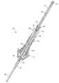
- FIG. 1is a perspective view of a robotic arm system used for positioning and orienting a pair of coaxially-disposed cannulas extending from a distal opening of a tool assembly housing carried by the robotic arm and used for harvesting and implanting human hair follicular units.
- FIG. 2is a close-up of the distal portion of the tool assembly housing shown in FIG. 1 .
- FIG. 3is a perspective view of a multi-part tool for use in the tool assembly in the system of FIG. 1 .
- FIG. 4is lengthwise sectional view of the multi-part tool of FIG. 3 .
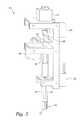
- FIG. 5is a perspective view of a motor drive assembly for operatively coupling with the multi-part-part tool of FIG. 3 in the tool assembly of the system of FIG. 1 .
- FIGS. 6A and 6Bare simplified, partially cut-away views of alternative implantation procedures carried out using the three-part tool of FIG. 3 .
- FIG. 7is a partial-schematic, partial perspective view of one embodiment of the tool assembly of the robotic system in FIG. 1 .
- FIG. 8is a partially cut-away sectional view of a holding unit located within a motor drive assembly in the tool assembly of FIG. 7 .
- FIG. 9Ais a lengthwise sectional view of a multi-part tool for use in the tool assembly in the system of FIG. 7 .
- FIGS. 9B-9Dillustrate variations of a distal end of a follicular unit harvesting cannula needle of the tool assembly of FIG. 9A .
- FIG. 10illustrates the multi-part tool of FIG. 9A operatively engaged with the holding unit of FIG. 8 .
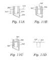
- FIGS. 11A-Dillustrate a process for implanting a follicular unit, in accordance with some embodiments.
- FIGS. 1 and 2depict an image-guided robotics system 25 , including a robotic arm 27 with a tool assembly 30 attached to a distal tool plate 20 .
- the tool assembly 30includes coaxially disposed harvesting and implanting cannulas 38 and 36 , respectively, extending from a tubular extension 24 of a housing 22 .
- the cannulas 36 and 38are axially stiff, e.g., made of a hard metal or plastic, and thin-walled to facilitate tissue penetration.
- the implanting cannula 36has a needle-like tissue piecing tip, and the harvesting cannula has a tissue-coring (e.g., serrated) tip.
- the robotic arm 27automatically and precisely positions the respective harvesting and implanting cannulas 38 and 36 at desired locations, and in desired orientations, along a body surface (e.g., a scalp) of a patient based on control signals derived at least in part from image data acquired by one or more cameras 28 attached to the tool assembly housing 22 .
- Such automatic and precise positioning of the respective harvesting and implanting cannulas 38 and 36is provided with a high degree of repeatability and accuracy (e.g. to 20 microns) by respective motors and encoders located in respective arm joints 21 of the robotic arm 27 .
- Hair transplantationgenerally includes three steps: follicular unit harvesting, recipient site incision, and follicular unit placement in the incision.
- FIG. 3shows one embodiment of a three-part tool 32 used for performing all three of these functions. Although the ensuing description of the three-part tool 32 is with reference to its use as part of the tool assembly 30 carried on the robotic arm 27 in the system 25 of FIG. 1 , it will be appreciated that hand-held and operated embodiments of the three-pad tool 32 are also possible.
- the three-part tool 32includes an outer (“implanting”) cannula 36 having an open, tissue-piercing (e.g., beveled) distal end 37 used for making incisions at recipient (implantation) sites in a body surface.
- An inner (“harvesting”) cannula 38is coaxially positioned in an interior lumen of the implanting cannula 36 , and has an open, tissue-coring (e.g., rough or serrated) distal end 40 .
- the harvesting cannula 38has an interior lumen appropriately sized for harvesting singular human hair follicular units by coring the respective follicular units and extracting them from a body surface (typically but not necessarily a scalp).
- embodiments of the harvesting cannula 38may have interior lumens that range from approximately 0.3 millimeters to 2.0 millimeters in diameter.
- the harvesting cannula lumenhas a diameter that is approximately 1 millimeter in diameter.
- different sized harvesting cannulas 38may be used for harvesting single-follicle follicular units than for harvesting multi-follicle follicular units.
- an inner wall surface of the harvesting cannula lumenmay be textured to facilitate frictional grasping the respective follicular units for extraction from the body surface after they are cored.
- the tool assembly 30includes a motor drive assembly 60 mounted in the housing 22 and configured to receive and operatively engage the component parts of the three-part tool 32 .
- the implanting cannula 36is fixedly attached to a proximal hub 34 , including a distal facing tapered portion 34 a and a proximally directed engagement portion 34 b .
- the engagement portion 34 bmay be detachably-coupled (snap-fit) with a resilient gripper 63 extending from a tubular sleeve 65 in the motor drive assembly 60 .
- the gripper 63comprises a plurality of resilient arm members 67 that are attached to or integral with, the tubular sleeve 65 .
- the tubular sleeve 65engages a rack-and-pinion drive mechanism 81 driven by a first motor 62 of the motor drive assembly 60 , so that, when the hub 34 is coupled to the gripper 63 , the motor 62 /drive mechanism 81 provide axial (i.e., reciprocating) motion of the implanting cannula 36 relative to the harvesting cannula 38 (and also relative to the tool assembly housing 22 / 24 ).
- the harvesting cannula 38extends proximally through a bore 45 of the implanting cannula hub 34 and implanting cannula 36 , and is fixedly attached to distal chuck portion 43 a of a pin vise 43 seated in, and rotatable relative to, a bore of hub 34 .
- An elongate body 46is seated in, and fixedly attached to, the pin vise 43 , and includes one or more radially-outward extending flanges 48 that engage a corresponding set of slots (not shown) in a distally projecting tubular drive member (not shown—extends internally through housing 93 ) coupled to an output gear 87 driven by a second motor 64 of the motor drive assembly 60 for thereby rotating the respective elongate body 65 and harvesting cannula 38 , respectively, about a longitudinal axis of the harvesting cannula 38 .
- a belt drive or other means for rotating the tubular drive member (and, thereby, the harvesting cannula 38 )may be used in alternative embodiments.
- the elongate body 46further includes a recessed section 44 located proximally of the flanges 48 , which seats an annular retaining member 50 for detachably-coupling (via a snap-fit type connection) with the tubular drive member (proximal of the slots that engage flanges 48 ), thereby retaining the harvesting cannula 38 in position when the tool 32 is coupled with the motor dive assembly 60 .
- An elongate obturator 52is slidably positioned in an interior lumen of the harvesting cannula 38 , and has a proximal end attached to a seating member 54 that engages with a linear (“screw-drive”) drive mechanism (not shown) driven by a third motor 66 of the motor drive assembly 60 for selectively providing a distally-directed, “pushing” force on the obturator 52 relative to the harvesting cannula 38 .
- a spring 53is seated in an annular recess 49 formed in a proximal end-cap 51 of the elongate body 46 , and extends (over the obturator 52 ) to the distal side of the seating member 54 . The spring 53 applies a proximally-directed, “pulling” force on the seating member, to thereby bias the obturator against the screw drive.
- the drive motor assemblyfurther includes a “release” motor 67 , that applies a distally-directed (pushing) force against the end-cap 51 via a tubular release member 86 , which causes the respective attachment couplings (i.e., the implanting cannula hub 34 b and gripper 63 , and the harvesting cannula retaining member 50 and the tubular drive member) to decouple for removal of the tool 32 from the tool assembly 30 , e.g., for replacing one or both of the implanting and harvesting cannulas 36 and 38 .
- a “release” motor 67that applies a distally-directed (pushing) force against the end-cap 51 via a tubular release member 86 , which causes the respective attachment couplings (i.e., the implanting cannula hub 34 b and gripper 63 , and the harvesting cannula retaining member 50 and the tubular drive member) to decouple for removal of the tool 32 from the tool assembly 30 , e
- the multi-part tool 32may be loaded into the tool assembly 30 by insertion (in the proximal direction) of the tool 32 (“back loaded”) through the tubular extension 24 of the housing 22 , until the respective couplings 34 b and 50 snap into place with their counterparts in the motor drive assembly 60 , and released by application of a sufficient force by the motor 67 on the release member 86 to decouple the respective couplings.
- a stop member 55is attached to the obturator 52 that abuts the distal side of the end-cap as the release member 86 applies a downward force on the end-cap 51 , so that the obturator 52 accompanies the rest of the tool 32 as it is released from the motor drive assembly 60 (and from the tool assembly 30 ).
- the motor drive assembly 60further comprises control circuitry for controlling operation of the respective motors 62 , 64 , 66 , and 67 .
- the control circuitrymay include an independent processor (not shown) associated with the motor drive assembly 60 , which receives as inputs information from the robotic system 25 , including but not limited to positioning data obtained from images acquired of the respective cannulas 36 , 38 and body surface/objects (e.g., hair follicles).
- a respective encodermay be operatively coupled with one or more of the motors 62 , 64 , 66 , and 67 for tracking the relative movement and, thus, position information, of the implanting cannula 36 , harvesting cannula 38 , and/or obturator 52 .
- the robotic arm 27positions and aligns the harvesting cannula 38 with a longitudinal axis of a selected follicular unit to be harvested.
- the harvesting cannula 38is then advanced over the selected follicular unit by motion of the robotic arm 27 , accompanied by simultaneous rotational movement of the harvesting cannula 38 about its longitudinal axis by the motor 64 , with the open distal end 40 of the cannula 38 penetrating the body surface into the subcutaneous fatty layer surrounding and underlying the follicular unit.
- a linear drive mechanismmay be additionally provided in the motor drive assembly 60 for providing independently controlled axial translation of the harvesting cannula 38 relative to the tool assembly housing 20 (and implanting cannula 36 ).
- the harvesting cannula 38is then withdrawn from the body surface by motion of the robotic arm 27 to thereby extract the follicular unit, which is carried in the lumen of the harvesting cannula.
- a vacuum sourcemay be selectively placed in communication with the harvesting cannula lumen to apply a proximally-directed “pulling” force to facilitate grasping and extracting the follicular unit, as well as to help retain the follicular unit in the harvesting cannula lumen after it has been harvested.
- the tool assembly 30is repositioned by the robotic arm 27 to a selected implantation site on the body surface.
- a longitudinal axis of the implanting cannula 36is preferably aligned with a desired orientation of the follicular unit, when implanted.
- the tissue-piercing distal end 37 of the implanting cannula 36is advanced over the harvesting cannula 38 and into the body surface 68 , creating a subcutaneous implantation cavity 70 of an appropriate depth and size for receiving the harvested follicular unit 72 .
- This puncture motion by the cannula 36is automatically controlled by motor 62 , and is preferably very rapid in order to minimize trauma to the tissue surface 74 of the implantation cavity 70 .
- the follicular unit 72is moved axially by the obturator 52 (under the control of motor 66 ) from the harvesting cannula lumen 76 , where it has remained undisturbed since it was harvested, into a distal end portion of the implanting cannula lumen 78 .
- This repositioning of the follicular unit 72 from the harvesting cannula lumen 76 into the implanting cannula lumen 78may take place before, during, or after the implanting cannula 36 has punctured the body surface 68 .
- the obturatorthereafter maintains the follicular unit 72 in the implantation cavity 70 as the implanting cannula 36 is withdrawn from the body surface 68 by translational movement relative to the obturator 52 .
- the obturator 52is also withdrawn, with the follicular unit 72 implanted in the body surface.
- a distal facing end 80 of the obturator 52is preferably recessed to allow room for one or more hair follicles 82 protruding from the follicular unit 72 .
- the respective distal ends of the implanting and harvesting cannulas 36 and 38are aligned (i.e., by relative movement of the implanting cannula 36 ) so that their respective distal ends 37 and 40 are approximately coextensive.
- This alignment of the respective cannula distal ends 37 and 40may take place before, during, or after the implanting cannula penetrates the body surface to form the implantation cavity 70 .
- the respective cannulas 36 and 38are withdrawn from the implantation cavity 70 , while the follicular unit 72 is retained therein, i.e., by simultaneous movement of the robotic arm 27 away from the body surface 68 and of the obturator 52 towards the body surface 68 .
- the respective cannulas 36 and 38may be withdrawn from the implantation cavity 70 relative to (and without requiring simultaneous movement of) the obturator 52 by operation of the motor drive assembly 60 .
- a source of pressurized air selectively placed in communication with the harvesting cannula lumen 76may be used to retain the follicular unit 72 in the implantation cavity 70 as the cannulas 36 and 38 are withdrawn.
- FIG. 7illustrates a distal portion of the robotics system 25 in accordance with some embodiments of the invention.
- a force sensor 100is secured to an arm 104 , a plate 102 mounted to the force sensor 100 , and a motor drive, or “positioning” assembly 106 secured to the plate 102 .
- the plate 102could be secured directly to the arm 104 , in which cases, the force sensor 100 may be secured between the positioning assembly 106 and the plate 102 .
- the force sensor 100may be located within the positioning assembly 106 .
- the force sensor 100is configured to sense three forces Fx, Fy, Fz in three different orthogonal directions X, Y, Z, and three orthogonal moments Mx, My, Mz.
- the force sensor 100may be configured to sense one or two of the forces Fx, Fy, Fz, and/or one or two of the moments Mx, My, Mz. As shown in the figure, the force sensor 100 is coupled to a computer 120 , which receives data from the force sensor 100 representing the sensed force(s) and/or moment(s). In other embodiments, the force sensor data may go directly to the robot.
- the force sensor 100monitors one or more force/moment component transmitted from the positioning assembly 106 .
- the force sensor 100may monitor a force Fz, which has a directional vector that is approximately parallel to an axis of a harvesting cannula 200 .
- the sensed force Fzis transmitted to the computer 120 , which determines whether a magnitude of the sensed force Fz is within an acceptable limit.
- the computer 120is configured (e.g., programmed) to stop a harvest process or an implant process if the sensed force Fz exceeds a prescribed limit, which may indicate that the harvesting cannula 200 or the implanting cannula 202 is pressing against the skull, for example.
- the force sensor 100provides a safety feature that prevents the harvesting cannula 200 and the implanting cannula 202 from injuring a patient in an unintended way.
- the positioning assembly 106includes a holding unit 109 for engagement with a cannula assembly 110 , and a plurality of positioners 107 a - 10 c .
- the holding unit 109is configured to engage with different parts of the cannula assembly 110 so that the cannula assembly 110 , as a whole, can be positioned by the positioning assembly 106 .
- the holding unit 109also allows different components of the cannula assembly 110 to be controlled after the cannula assembly 110 is engaged with the holding unit 109 .
- the positioners 107 a - 107 care configured for moving different components of the cannula assembly 110 after it has been engaged with the holding unit.
- the positioning assembly 106may include more or less than three positioners 107 .
- the positioning assembly 106may include the motor drive assembly of FIG. 5 , which includes three motors (positioners) for moving different components of the cannula assembly 110 , plus an additional motor for disengaging the cannula assembly 110 from the positioning assembly.
- FIG. 8illustrates the holding unit 109 in accordance with some embodiments.
- the holding unit 109includes a first engagement portion 122 for engaging a first portion of the cannula assembly 110 , a second engagement portion 124 for engaging a second portion of the cannula assembly 110 , and a third engagement portion 126 for engaging a third portion of the cannula assembly 110 .
- FIG. 9Aillustrates the cannula assembly 110 in accordance with some embodiments.
- the cannula assembly 110has a similar configuration as the tool 32 shown in FIGS. 3-4 .
- the cannula assembly 110includes a harvesting cannula 200 , an implanting cannula 202 , and a plunger (obturator) 204 .
- the harvesting cannula 200has a proximal end 212 , a distal end 214 , a body 215 extending between the proximal and distal ends 212 , 214 , and a lumen 217 defined at least partially by the body 215 .
- the lumen 217has a cross sectional dimension that is between 0.3 millimeter and 2.0 millimeters, and more preferably, approximately 1 millimeter.
- the cannula assembly 110further includes a shaft 216 having a proximal end 218 , a distal end 220 , and a lumen 222 extending between the proximal and distal ends 218 , 220 .
- the proximal end 212 of the harvesting cannula 200is secured to the distal end 220 of the shaft 216 .
- the implanting cannula 202has a proximal end 232 , a distal end 234 , a body 230 extending between the proximal and distal ends 232 , 234 , and a lumen 236 within the body 230 .
- the lumen 236has a cross sectional dimension sized for accommodating at least a portion of the harvesting cannula 200 , and for allowing the harvesting cannula 200 to slide relative to the implanting cannula 202 .
- the distal end 234 of the implanting cannula 202has a sharp tip 250 for piercing tissue.
- the distal end 214 of the harvesting cannula 200has a tubular configuration ( FIG. 9B ).
- the edge 252 of the harvesting cannula 200may have a sharp configuration for allowing the harvesting cannula 200 to penetrate tissue.
- the distal end 214 of the harvesting cannula 200may have an arc configuration ( FIG. 9C ).
- the ends 254 of the arc portionmay have a sharp configuration for allowing the harvesting cannula 200 to cut tissue as the harvesting cannula 200 is rotated about its axis.
- the distal end 214 of the harvesting cannula 200can include a plurality of cutting portions 256 , with each cutting portion 256 having a sharp edge 258 for cutting tissue ( FIG. 9D ). It should be noted that the distal end 214 of the harvesting cannula 200 is not limited to the examples described previously, and that the distal end 214 can have other configurations in other embodiments, as long as it can core tissue.
- the cannula assembly 110further includes a first engagement portion 238 and a second engagement portion 240 .
- the first engagement portion 238has a tubular configuration, and is secured to the shaft 216 .
- the second engagement portionalso has a tubular configuration, and is secured to the proximal end 232 of the implanting cannula 202 .
- proximal end 232 of the implanting cannula 202.
- the first and the second engagement portions 238 , 240are sized and shaped to engage with corresponding components of the holding unit 109 . It should be noted that the first and second engagement portions 238 , 240 are not limited to the example of the configuration illustrated, and that the engagement portions 238 , 240 can have other configurations in other embodiments.
- the engagement portion 238does not have a tubular configuration.
- the engagement portion 238can be a structure that is secured to, or extends from, a surface of the shaft 216 .
- the engagement portion 240can be a structure that is secured to, or extends from, a surface of the implanting cannula 202 , and needs not have a tubular configuration.
- the cannula assembly 110also includes a connector 248 secured to the shaft 216 .
- the connector 248has a shape that resembles a sphere, but may have other shapes in other embodiments.
- the plunger 204has a proximal end 242 and a distal end 244 .
- the plunger 204is at least partially located within the lumen 217 of the harvesting cannula 200 , and is slidable relative to the harvesting cannula 200 .
- the cannula assembly 110further includes a spring 246 coupled to the plunger 204 for biasing the plunger 204 in a proximal direction relative to the harvesting cannula 200 .
- the plunger 204is described as a component of the cannula assembly 110 . In other embodiments, the plunger 204 is not a part of the cannula assembly 110 .
- the plunger 204may be a component of the positioning assembly 106 .
- FIG. 10illustrates the cannula assembly 110 that has been engaged with the positioning assembly 106 .
- the first engagement portion 122 of the holding unit 109is engaged with the connector 248
- the second engagement portion 124is engaged with the first engagement portion 238 of the cannula assembly 110
- the third engagement portion 126is engaged with the second engagement portion 240 of the cannula assembly.
- the connector 248allows the cannula assembly 110 to be detachably secured to the positioning assembly 106 .
- the first engagement portion 122 of the holding unit 109is coupled to the first positioner 107 a .
- the harvesting cannula 200is not translatable.
- the first positioner 107 ais configured to translate (e.g., advance or retract) the harvesting cannula 200 .
- the second engagement portion 124 of the holding unit 109is coupled to the second positioner 107 b , which is configured to rotate the harvesting cannula 200 about its axis.
- the third engagement portion 126 of the holding unit 109is coupled to the third positioner 107 c , which is configured to translate (e.g., advance or retract) the implanting cannula 202 .
- the second engagement portion 124 of the holding unit 109may be coupled to both the first positioner 107 a and the second positioner 107 b .
- the first positioner 107 ais configured to translate the engagement portion 124 to thereby advance or retract the harvesting cannula 200
- the second positioner 107 bis configured to rotate the engagement portion 124 to thereby turn the harvesting cannula 200 about its axis.
- the second positioner 107 bis not needed, and the cannula assembly 110 does not include the engagement portion 238 .
- the positioning assembly 106is not configured to rotate the harvesting cannula 200 , but to advance and retract the harvesting cannula 200 in a back and forth trusting motion.
- the third positioner 107 cis not needed, and the third engagement portion 126 is fixedly secured to the holding unit 109 .
- the implanting cannula 202may be positioned by the robotic arm 27 , and the harvesting cannula 200 may be positioned relative to the implanting cannula 202 using the first positioner 107 a.
- the cannula assembly 110When using the cannula assembly 110 to harvest a follicular unit, the cannula assembly 110 is first coupled to the positioning assembly 106 . Such may be accomplished manually by snapping the cannula assembly 110 onto the positioning assembly 106 . Alternatively, the cannula assembly 110 may be held upright by a stand (not shown). In such cases, the robotic arm 27 may be used to move the positioning assembly 106 to “grab” the cannula assembly 110 from the stand. The camera(s) 28 may be used to provide information regarding a position of the cannula assembly 110 to the processor 120 , which controls the robotic arm 27 based on the information, thereby placing the positioning assembly 106 in engagement position relative to the cannula assembly 110 .
- the treatment planis a prescribed plan designed to transplant hair follicular units from a first region (harvest region) to a target region (implant region).
- the treatment planmay include one or more parameters, such as a number of hair follicular units to be removed/implanted, location of harvest region, location of implant region, a degree of randomness associated with targeted implant locations, spacing between adjacent targeted implant locations, depth of follicle, depth of implant, patient identification, geometric profile of harvest region, geometric profile of implant region, marker location(s), and density of targeted implant locations.
- Various techniquesmay be used to input the treatment plan into the computer 120 .
- the treatment planmay be input using a user interface that includes a monitor 122 and a keyboard 124 .
- the treatment planmay be input using a storage device, such as a diskette or a compact disk.
- the treatment planmay be downloaded from a remote server.
- the treatment planmay be input using a combination of the above techniques. For example, some parameters may be input into the computer 120 using a diskette, while other parameters may be input using the user interface. In some embodiments, one or more parameters of the treatment plan may be determined in real time (e.g., during a treatment session).
- the computer 120After the treatment plan has been input into the computer 120 , the computer 120 then registers the treatment plan with a patient. In some embodiments, such may be accomplished by using the camera(s) 28 to identify one or more markers on the patient.
- the markermay be a reflector that is secured to the patient, an ink mark drawn on the patient, or an anatomy of the patient.
- the identified marker(s)may be used to determine a position and/or orientation of a target region on the patient.
- the treatment planincludes a position of the harvest (or donor) region.
- the computer 120identifies the location of the harvest region on the patient, and a target follicular unit in the harvest region.
- the computer 120then operates the robotic arm 27 to place the distal end 214 of the harvesting cannula 200 next to the target follicular unit.
- the harvesting cannula 200is positioned coaxially with the target follicular unit.
- the harvesting cannula 200is used to harvest the target follicular unit. In some embodiments, such may be accomplished by activating a positioner within the positioning assembly 106 to rotate the harvesting cannula 200 . As the harvesting cannula 200 is rotated, the harvesting cannula 200 may be advanced distally (e.g., by activating another positioner within the positioning assembly 106 , or by moving the positioning assembly 106 using the robotic arm 27 ). In other embodiments, the harvesting of the target follicle 302 unit may be accomplished by thrusting the harvesting cannula 200 forward and backward.
- the implanting cannula 202is located proximally away from the distal end 214 of the harvesting cannula 200 to thereby prevent interference with the harvesting procedure. Such may be accomplished by advancing the harvesting cannula 200 distally relative to the implanting cannula 202 , or alternatively, by retracting the implanting cannula 202 proximally relative to the harvesting cannula 200 (if the implanting cannula 202 can be positioned).
- the harvesting cannula 200When the distal end 214 of the harvesting cannula 200 has been advanced within a prescribed depth, e.g., 5 millimeter, below the skin surface, the harvesting cannula 200 is then retracted and removed from the patient.
- the camera(s) 28may be used to monitor the harvesting process to thereby determine how far the harvesting cannula 200 has been advanced below the skin surface 306 .
- the exterior of the harvesting cannula 200may include marker lines to thereby allow the camera(s) 28 or a physician to “see” how much of the harvesting cannula 200 has been advanced into the patient.
- a proximal end of the cannula assembly 110may be coupled to a vacuum unit (not shown) located within the positioning assembly 106 . In such cases, the vacuum unit creates suction within the lumen 217 of the harvesting cannula 200 , to thereby pull the target follicular unit 302 away from its underlying tissue as the harvesting cannula 200 is removed from the patient.
- the positioning assembly 106retracts the harvesting cannula 200 proximally until the distal end 214 is proximal to the distal end 234 of the implanting cannula 202 .
- the implanting cannula 202may be advanced distally until the distal end 234 is distal to the distal end 214 of the harvesting cannula 200 .
- the computer 120operates the robotic arm 27 to place the distal end 234 of the implanting cannula 202 adjacent to a target location within an implant region of the patient as prescribed by the treatment plan.
- the implanting cannula 202is then advanced (e.g., by activating a positioner within the positioning assembly 106 , or by moving the positioning assembly 106 distally towards the target location) to pierce through the skin 310 at the implant region ( FIG. 11A ).
- the implanting cannula 202is advanced until the penetrated depth 312 is at least equal to the coring depth 300 .
- the camera(s) 28 and the computer 120may be used to determine an amount of the implanting cannula 202 that has been advanced into the patient.
- the implanting cannula 202may include a plurality of marker lines for allowing the camera(s) 28 or a physician to “see” how much of the implanting cannula 202 has been inserted into the patient. As shown in the figure, the implanting cannula 202 creates an opening 314 below the patient's skin 314 , in which the follicular unit 302 may be placed.
- the harvesting cannula 200which contains the harvested follicular unit 302 , is advanced within the lumen 236 of the implanting cannula 202 , until a top surface 320 of the follicular unit 302 is at or below the skin 310 at the implant region ( FIG. 11B ).
- the plunger 204may be advanced distally (e.g., by using another positioner within the positioning assembly 106 ) until its distal end 244 engages with the follicular unit 302 located within the harvesting cannula 200 ( FIG. 11C ).
- the implanting cannula 202 and the harvesting cannula 200are then retracted proximally relative to the plunger 204 , thereby leaving the follicular unit 302 implanted at the target location in the implant region ( FIG. 11D ).
- the cannula assembly 110does not include the plunger 204 .
- a pressure generator(not shown) located within the positioning assembly 106 may be used to create a pressure within the lumen 217 of the harvesting cannula 200 , thereby pushing the follicular unit 302 towards the patient as the implanting cannula 202 and the harvesting cannula 200 is retracted.
- Such techniquewill cause the follicular unit 302 to dislodge from the harvesting cannula 200 while the harvesting cannula 200 is being removed from the patient.
- the harvesting cannula 200is advanced distally until its distal end 214 is distal to the distal end 234 of the implanting cannula 202 .
- the computer 120then operates the robotic arm 27 again to place the harvesting cannula 200 next to another target follicular unit 302 to be harvested.
- the above described processis then repeated to harvest the next follicular unit 302 , and to implant the follicular unit 302 .
- the selection of the follicular unit 302may be determined by the computer 120 .
- the computer 120selects a follicular unit 302 only if it is within the prescribed harvest region. In some embodiments, the above process is repeated until a prescribed number of follicular units 302 have been implanted in the implant region, until a density of the implanted follicle units 302 reaches a prescribed density, or until there is no more available follicular unit 302 in the harvest region.
- an attending physician or operatormay still specify where a follicular unit needs to be implanted and at what angle, i.e., its relative location (or “implantation site”), orientation, and depth.
- a location, orientation, and/or depth of a follicular unit to be implantedmay be carried out by a treatment planning system.
- the attending operatormay use a user interface (e.g., a conventional computer mouse) to specify the implant location and/or position and/or orientation and/or implant depth.
- the operatorcan point to location on the scalp by placing a temporary fiducial, such as an ink mark or a pointer that can be visualized, identified, and measured by the image processing system.
- a temporary fiducialsuch as an ink mark or a pointer that can be visualized, identified, and measured by the image processing system.
- orientationcan be specified directly on the computer monitor as a combination of two angles, such as rotation about x-axis and a rotation about y-axis (assuming that z-axis is along the cannula), or by placing an elongated pointer on the scalp, which the image processing system can visualize and measure the angles.
- the control of the robotic armnow becomes two steps. First, based on the specification of the location and orientation of the implant location, the computer processor directs the robotic arm to move the implanting cannula to a desired location and orientation. Second, the actual advancement of the implanting cannula into the skin surface takes place, either solely by actuating the mechanism, or by a combination of robotic arm movement and mechanism actuation, in which the desired implant depth is achieved.
- Another way of specifying the orientation of the implanted follicular unitis to have the system match to the orientation of the one or more hair follicles extending there from to the orientation of existing hair follicles in the area of implantation.
- the systemafter positioning the implanting cannula at the implantation location, visualizes and measures the orientation of neighboring hair follicles, and uses this information to determine an appropriate orientation of the follicular unit being implanted.
- the systemmay, for example, obtain a weighted average of the various orientations for determining an orientation of the follicular unit being implanted.
Landscapes
- Health & Medical Sciences (AREA)
- Surgery (AREA)
- Life Sciences & Earth Sciences (AREA)
- Engineering & Computer Science (AREA)
- Molecular Biology (AREA)
- Public Health (AREA)
- Heart & Thoracic Surgery (AREA)
- Medical Informatics (AREA)
- Nuclear Medicine, Radiotherapy & Molecular Imaging (AREA)
- Animal Behavior & Ethology (AREA)
- General Health & Medical Sciences (AREA)
- Biomedical Technology (AREA)
- Veterinary Medicine (AREA)
- Oral & Maxillofacial Surgery (AREA)
- Pathology (AREA)
- Robotics (AREA)
- Prostheses (AREA)
- Manipulator (AREA)
- Surgical Instruments (AREA)
Abstract
Description
Claims (29)
Priority Applications (20)
| Application Number | Priority Date | Filing Date | Title |
|---|---|---|---|
| US11/421,443US7621934B2 (en) | 2005-09-30 | 2006-05-31 | Methods of harvesting and implanting follicular units using a coaxial tool |
| EP14166987.9AEP2781200B1 (en) | 2005-09-30 | 2006-09-27 | Automated systems and methods for harvesting and implanting follicular units |
| PCT/US2006/038002WO2007041267A2 (en) | 2005-09-30 | 2006-09-27 | Automated systems and methods for harvesting and implanting follicular units |
| CA2763686ACA2763686C (en) | 2005-09-30 | 2006-09-27 | Systems and methods for aligning a tool with a desired location of object |
| ES14166987.9TES2694293T3 (en) | 2005-09-30 | 2006-09-27 | Automated systems and methods for collecting and implanting follicular units |
| AU2006297217AAU2006297217B2 (en) | 2005-09-30 | 2006-09-27 | Automated systems and methods for harvesting and implanting follicular units |
| KR1020087007549AKR101015670B1 (en) | 2005-09-30 | 2006-09-27 | Automatic device for harvesting and transplanting hair follicle units |
| BRPI0616648-2ABRPI0616648A2 (en) | 2005-09-30 | 2006-09-27 | automated systems and methods for follicular unit harvesting and implantation |
| KR1020107010548AKR101155258B1 (en) | 2005-09-30 | 2006-09-27 | Apparatus and methods for harvesting and implanting follicular units |
| ES06804246.4TES2522283T3 (en) | 2005-09-30 | 2006-09-27 | Automated systems to collect and implant follicular units |
| EP20100168186EP2228028B1 (en) | 2005-09-30 | 2006-09-27 | Apparatus for harvesting and implanting follicular units |
| CN200680035954XACN101277657B (en) | 2005-09-30 | 2006-09-27 | Automated system and method for harvesting and implanting follicular units |
| CA2621594ACA2621594C (en) | 2005-09-30 | 2006-09-27 | Automated systems and methods for harvesting and implanting follicular units |
| CA2709769ACA2709769C (en) | 2005-09-30 | 2006-09-27 | Tool assembly for harvesting and implanting follicular units |
| CN2010102304592ACN101926678B (en) | 2005-09-30 | 2006-09-27 | Automated systems and methods for harvesting and implanting follicular units |
| EP06804246.4AEP1928340B1 (en) | 2005-09-30 | 2006-09-27 | Automated systems for harvesting and implanting follicular units |
| JP2008533646AJP4995826B2 (en) | 2005-09-30 | 2006-09-27 | Automatic system for collection and transplantation of hair follicle units |
| AU2010202789AAU2010202789B2 (en) | 2005-09-30 | 2010-07-01 | Automated systems and methods for harvesting and implanting follicular units |
| JP2010164551AJP5099790B2 (en) | 2005-09-30 | 2010-07-22 | Automatic system for collection and transplantation of hair follicle units |
| JP2012129216AJP5502936B2 (en) | 2005-09-30 | 2012-06-06 | Automatic system for collection and transplantation of hair follicle units |
Applications Claiming Priority (4)
| Application Number | Priority Date | Filing Date | Title |
|---|---|---|---|
| US72252105P | 2005-09-30 | 2005-09-30 | |
| US75360205P | 2005-12-22 | 2005-12-22 | |
| US76417306P | 2006-01-31 | 2006-01-31 | |
| US11/421,443US7621934B2 (en) | 2005-09-30 | 2006-05-31 | Methods of harvesting and implanting follicular units using a coaxial tool |
Publications (2)
| Publication Number | Publication Date |
|---|---|
| US20070078473A1 US20070078473A1 (en) | 2007-04-05 |
| US7621934B2true US7621934B2 (en) | 2009-11-24 |
Family
ID=37902829
Family Applications (4)
| Application Number | Title | Priority Date | Filing Date |
|---|---|---|---|
| US11/380,903AbandonedUS20070078466A1 (en) | 2005-09-30 | 2006-04-28 | Methods for harvesting follicular units using an automated system |
| US11/421,443Active2028-09-21US7621934B2 (en) | 2005-09-30 | 2006-05-31 | Methods of harvesting and implanting follicular units using a coaxial tool |
| US11/421,438Active2028-06-15US7621933B2 (en) | 2005-09-30 | 2006-05-31 | Tool assembly for harvesting and implanting follicular units |
| US12/577,362Active2026-10-30US8133247B2 (en) | 2005-09-30 | 2009-10-12 | Tool assembly for harvesting and implanting follicular units |
Family Applications Before (1)
| Application Number | Title | Priority Date | Filing Date |
|---|---|---|---|
| US11/380,903AbandonedUS20070078466A1 (en) | 2005-09-30 | 2006-04-28 | Methods for harvesting follicular units using an automated system |
Family Applications After (2)
| Application Number | Title | Priority Date | Filing Date |
|---|---|---|---|
| US11/421,438Active2028-06-15US7621933B2 (en) | 2005-09-30 | 2006-05-31 | Tool assembly for harvesting and implanting follicular units |
| US12/577,362Active2026-10-30US8133247B2 (en) | 2005-09-30 | 2009-10-12 | Tool assembly for harvesting and implanting follicular units |
Country Status (1)
| Country | Link |
|---|---|
| US (4) | US20070078466A1 (en) |
Cited By (21)
| Publication number | Priority date | Publication date | Assignee | Title |
|---|---|---|---|---|
| US20080234697A1 (en)* | 2007-03-19 | 2008-09-25 | Restoration Robotics, Inc. | Device and method for harvesting and implanting follicular units |
| US20100030234A1 (en)* | 2005-09-30 | 2010-02-04 | Mohan Bodduluri | Tool Assembly for Harvesting and Implanting Follicular Units |
| US20100210967A1 (en)* | 2007-08-02 | 2010-08-19 | Sjunnesson Haakan | Surgical kits and methods |
| US8128639B2 (en) | 2010-05-20 | 2012-03-06 | Restoration Robotics, Inc. | Tools and methods for harvesting follicular units |
| US20120184969A1 (en)* | 2011-01-18 | 2012-07-19 | Melendez Tomas | Automated Delivery of Fluid |
| CN102657548A (en)* | 2012-04-25 | 2012-09-12 | 天津大学 | Reversing nuclear magnetic compatible puncture needle clamp |
| US8298246B2 (en) | 2010-04-01 | 2012-10-30 | Restoration Robotics, Inc. | Follicular unit removal tool with pivoting retention member |
| US20130103151A1 (en)* | 2002-11-05 | 2013-04-25 | Medgenics Medical Israel Ltd | Dermal micro-organs, methods and apparatuses for producing and using the same |
| US8998931B2 (en) | 2011-10-17 | 2015-04-07 | Pilofocus, Inc. | Hair restoration |
| US9107896B2 (en) | 2001-11-05 | 2015-08-18 | Medgenics Medical Israel Ltd. | Dermal micro-organs, methods and apparatuses for producing and using the same |
| US9314082B2 (en) | 2009-09-17 | 2016-04-19 | Pilofocus, Inc. | System and method for extraction of hair follicle |
| US9364252B2 (en) | 2009-09-17 | 2016-06-14 | Pilofocus, Inc. | Hair restoration surgery |
| US9420866B1 (en)* | 2006-09-14 | 2016-08-23 | William Rassman | Hair harvesting apparatus |
| US9468667B2 (en) | 2001-11-05 | 2016-10-18 | Medgenics Medical Israel Ltd. | Dermal micro-organs, methods and apparatuses for producing and using the same |
| US9693799B2 (en) | 2009-09-17 | 2017-07-04 | Pilofocus, Inc. | System and method for aligning hair follicle |
| CN109330665A (en)* | 2018-08-29 | 2019-02-15 | 南京新生医疗科技有限公司 | Jewel knife with hair tally function |
| US11357515B2 (en) | 2017-09-09 | 2022-06-14 | June Access Ip, Llc | Intraosseous device having retractable motor/stylet assembly and automatic stylet point cover upon retraction operation |
| US11484339B2 (en) | 2017-09-09 | 2022-11-01 | June Access, IP LLC | Passive safety intraosseous device |
| US11896261B2 (en) | 2014-11-14 | 2024-02-13 | Cytrellis Biosystems, Inc. | Devices and methods for ablation of the skin |
| US12023226B2 (en) | 2013-02-20 | 2024-07-02 | Cytrellis Biosystems, Inc. | Methods and devices for skin tightening |
| US12178513B2 (en) | 2010-12-21 | 2024-12-31 | Venus Concept Inc. | Methods and systems for directing movement of a tool in hair transplantation procedures |
Families Citing this family (123)
| Publication number | Priority date | Publication date | Assignee | Title |
|---|---|---|---|---|
| US7806121B2 (en)* | 2005-12-22 | 2010-10-05 | Restoration Robotics, Inc. | Follicular unit transplantation planner and methods of its use |
| US10357184B2 (en)* | 2012-06-21 | 2019-07-23 | Globus Medical, Inc. | Surgical tool systems and method |
| DE112007001360B4 (en)* | 2006-06-05 | 2013-04-18 | Visicon Inspection Technologies Llc | Stent Inspection System |
| US7620144B2 (en) | 2006-06-28 | 2009-11-17 | Accuray Incorporated | Parallel stereovision geometry in image-guided radiosurgery |
| US7477782B2 (en)* | 2006-08-25 | 2009-01-13 | Restoration Robotics, Inc. | System and method for classifying follicular units |
| US20080049993A1 (en)* | 2006-08-25 | 2008-02-28 | Restoration Robotics, Inc. | System and method for counting follicular units |
| US7922688B2 (en) | 2007-01-08 | 2011-04-12 | Restoration Robotics, Inc. | Automated delivery of a therapeutic or cosmetic substance to cutaneous, subcutaneous and intramuscular tissue regions |
| US8036448B2 (en)* | 2007-04-05 | 2011-10-11 | Restoration Robotics, Inc. | Methods and devices for tattoo application and removal |
| WO2009002677A1 (en)* | 2007-06-26 | 2008-12-31 | Restoration Robotics, Inc. | Follicular unit harvesting tools including devices and their use for severing connective tissue |
| US8211134B2 (en) | 2007-09-29 | 2012-07-03 | Restoration Robotics, Inc. | Systems and methods for harvesting, storing, and implanting hair grafts |
| DE102007055203A1 (en)* | 2007-11-19 | 2009-05-20 | Kuka Roboter Gmbh | A robotic device, medical workstation and method for registering an object |
| US8152827B2 (en)* | 2008-01-11 | 2012-04-10 | Restoration Robotics, Inc. | Systems and methods for harvesting, storing, and implanting hair grafts |
| EP2231232B1 (en)* | 2008-01-17 | 2021-04-21 | Becton, Dickinson and Company | Drug containing device |
| US8226664B2 (en) | 2008-03-18 | 2012-07-24 | Restoration Robotics, Inc. | Biological unit removal tools with movable retention member |
| US20090254060A1 (en)* | 2008-04-02 | 2009-10-08 | Hetherington Hugh E | Motor assembly for injection control device |
| US9107697B2 (en)* | 2008-06-04 | 2015-08-18 | Restoration Robotics, Inc. | System and method for selecting follicular units for harvesting |
| US8652186B2 (en)* | 2008-06-04 | 2014-02-18 | Restoration Robotics, Inc. | System and method for selecting follicular units for harvesting |
| US8848974B2 (en) | 2008-09-29 | 2014-09-30 | Restoration Robotics, Inc. | Object-tracking systems and methods |
| US20100082042A1 (en)* | 2008-09-30 | 2010-04-01 | Drews Michael J | Biological unit removal tool with occluding member |
| WO2010041089A1 (en)* | 2008-10-06 | 2010-04-15 | Konstantinos Giotis P | Depilation device and method for the use thereof |
| EP2355720A4 (en)* | 2008-11-14 | 2015-11-11 | Cole Isolation Tech Llc | Follicular dissection device and method |
| US8241314B2 (en)* | 2009-01-15 | 2012-08-14 | Restoration Robotics, Inc. | Anti-popping devices and methods for hair implantation |
| US8388631B2 (en) | 2009-01-23 | 2013-03-05 | Restoration Robotics, Inc. | Skin tensioner for hair transplantation |
| US8048090B2 (en) | 2009-03-11 | 2011-11-01 | Restoration Robotics, Inc. | System and method for harvesting and implanting hair using image-generated topological skin models |
| US8454627B2 (en) | 2009-03-11 | 2013-06-04 | Restoration Robotics, Inc. | Systems and methods for harvesting and implanting hair using image-generated topological skin models |
| JP5622153B2 (en) | 2009-06-15 | 2014-11-12 | 国立大学法人大阪大学 | Magnetic stimulator |
| US20110046639A1 (en)* | 2009-08-24 | 2011-02-24 | Konstantinos Giotis | Method of direct hair implantation |
| US8900181B2 (en) | 2009-12-18 | 2014-12-02 | Srgi Holdings, Llc | Skin treatment and drug delivery device |
| US8465498B2 (en)* | 2010-01-15 | 2013-06-18 | Restoration Robotics, Inc. | Tensioning device and method for hair transplantation |
| KR101999730B1 (en)* | 2010-05-07 | 2019-07-12 | 더 제너럴 하스피탈 코포레이션 | Method and apparatus for tissue grafting and copying |
| US8986324B2 (en)* | 2010-08-13 | 2015-03-24 | Restoration Robotics, Inc. | Systems and methods for harvesting follicular units |
| US11000310B2 (en) | 2010-12-17 | 2021-05-11 | Srgi Holdings, Llc | Pixel array medical systems, devices and methods |
| US11278309B2 (en) | 2010-12-17 | 2022-03-22 | Srgi Holdings, Llc | Pixel array medical systems, devices and methods |
| US10967162B2 (en) | 2010-12-17 | 2021-04-06 | Srgi Holdings, Llc | Systems, devices and methods for fractional resection, fractional skin grafting, fractional scar reduction and fractional tattoo removal |
| US10856900B2 (en) | 2010-12-17 | 2020-12-08 | Srgi Holdings, Llc | Pixel array medical systems, devices and methods |
| US11103275B2 (en) | 2010-12-17 | 2021-08-31 | Srgi Holdings, Llc | Pixel array medical systems, devices and methods |
| US11109887B2 (en) | 2013-12-06 | 2021-09-07 | Srgi Holdings, Llc | Pixel array medical systems, devices and methods |
| US10219827B2 (en) | 2010-12-17 | 2019-03-05 | Srgi Holdings, Llc | Pixel array medical devices and methods |
| US10702684B2 (en) | 2010-12-17 | 2020-07-07 | Srgi Holdings, Llc | Systems, devices and methods for fractional resection, fractional skin grafting, fractional scar reduction and fractional tattoo removal |
| US10736653B2 (en) | 2013-12-06 | 2020-08-11 | Srgi Holdings, Llc | Pixel array medical systems, devices and methods |
| US10695546B2 (en) | 2010-12-17 | 2020-06-30 | Srgi Holdings, Llc | Systems, devices and methods for fractional resection, fractional skin grafting, fractional scar reduction and fractional tattoo removal |
| US10314640B2 (en) | 2010-12-17 | 2019-06-11 | Srgi Holdings, Llc | Pixel array medical devices and methods |
| US8911453B2 (en)* | 2010-12-21 | 2014-12-16 | Restoration Robotics, Inc. | Methods and systems for directing movement of a tool in hair transplantation procedures |
| CN102113905B (en)* | 2011-01-25 | 2012-08-29 | 天津大学 | Novel acupuncture surgery manipulator mechanism in nuclear magnetic resonance environment |
| MX347856B (en) | 2011-01-28 | 2017-05-16 | Massachusetts Gen Hospital | Method and apparatus for skin resurfacing. |
| EP2667805B1 (en)* | 2011-01-28 | 2023-04-05 | The General Hospital Corporation | Apparatus and method for tissue biopsy |
| WO2012125291A1 (en)* | 2011-03-15 | 2012-09-20 | Siemens Healthcare Diagnostics Inc. | Multi-view stereo systems and methods for tube inventory in healthcare diagnostics |
| ES2665038T3 (en) | 2011-04-20 | 2018-04-24 | Sanusi UMAR | Device for the extraction of follicular units |
| US8945150B2 (en) | 2011-05-18 | 2015-02-03 | Restoration Robotics, Inc. | Systems and methods for selecting a desired quantity of follicular units |
| US9188973B2 (en) | 2011-07-08 | 2015-11-17 | Restoration Robotics, Inc. | Calibration and transformation of a camera system's coordinate system |
| ES2833525T3 (en) | 2011-07-21 | 2021-06-15 | Massachusetts Gen Hospital | Apparatus for deteriorating and removing grease |
| KR101347114B1 (en)* | 2011-07-28 | 2014-01-15 | 김광수 | Mosquito mower with improved hair transplant precision |
| US9682249B2 (en)* | 2011-10-24 | 2017-06-20 | Teijin Pharma Limited | Transcranial magnetic stimulation system |
| CN102580231B (en)* | 2012-03-27 | 2013-06-12 | 天津大学 | Acupuncture manipulator mechanism for nuclear magnetic resonance environment |
| US12133699B2 (en) | 2012-06-21 | 2024-11-05 | Globus Medical, Inc. | System and method for surgical tool insertion using multiaxis force and moment feedback |
| US11963755B2 (en) | 2012-06-21 | 2024-04-23 | Globus Medical Inc. | Apparatus for recording probe movement |
| US11864839B2 (en) | 2012-06-21 | 2024-01-09 | Globus Medical Inc. | Methods of adjusting a virtual implant and related surgical navigation systems |
| US11045267B2 (en) | 2012-06-21 | 2021-06-29 | Globus Medical, Inc. | Surgical robotic automation with tracking markers |
| US11896446B2 (en) | 2012-06-21 | 2024-02-13 | Globus Medical, Inc | Surgical robotic automation with tracking markers |
| US10624710B2 (en) | 2012-06-21 | 2020-04-21 | Globus Medical, Inc. | System and method for measuring depth of instrumentation |
| US10874466B2 (en) | 2012-06-21 | 2020-12-29 | Globus Medical, Inc. | System and method for surgical tool insertion using multiaxis force and moment feedback |
| US11857149B2 (en) | 2012-06-21 | 2024-01-02 | Globus Medical, Inc. | Surgical robotic systems with target trajectory deviation monitoring and related methods |
| US11607149B2 (en)* | 2012-06-21 | 2023-03-21 | Globus Medical Inc. | Surgical tool systems and method |
| US10758315B2 (en) | 2012-06-21 | 2020-09-01 | Globus Medical Inc. | Method and system for improving 2D-3D registration convergence |
| US11253327B2 (en) | 2012-06-21 | 2022-02-22 | Globus Medical, Inc. | Systems and methods for automatically changing an end-effector on a surgical robot |
| US10799298B2 (en) | 2012-06-21 | 2020-10-13 | Globus Medical Inc. | Robotic fluoroscopic navigation |
| US11793570B2 (en) | 2012-06-21 | 2023-10-24 | Globus Medical Inc. | Surgical robotic automation with tracking markers |
| US11317971B2 (en) | 2012-06-21 | 2022-05-03 | Globus Medical, Inc. | Systems and methods related to robotic guidance in surgery |
| US11974822B2 (en) | 2012-06-21 | 2024-05-07 | Globus Medical Inc. | Method for a surveillance marker in robotic-assisted surgery |
| US11786324B2 (en) | 2012-06-21 | 2023-10-17 | Globus Medical, Inc. | Surgical robotic automation with tracking markers |
| US11857266B2 (en) | 2012-06-21 | 2024-01-02 | Globus Medical, Inc. | System for a surveillance marker in robotic-assisted surgery |
| US12004905B2 (en) | 2012-06-21 | 2024-06-11 | Globus Medical, Inc. | Medical imaging systems using robotic actuators and related methods |
| US11864745B2 (en) | 2012-06-21 | 2024-01-09 | Globus Medical, Inc. | Surgical robotic system with retractor |
| US9510913B2 (en)* | 2012-09-12 | 2016-12-06 | Restoration Robotics, Inc. | Skin tensioning devices and methods of their use |
| US10226113B2 (en)* | 2013-02-06 | 2019-03-12 | Michael Victor Lucido | Mechanical hair puller |
| US9392965B2 (en) | 2013-03-14 | 2016-07-19 | Restoration Robotics, Inc. | Method and apparatus for determining a change in tension of a body surface |
| US9408691B2 (en) | 2013-03-14 | 2016-08-09 | Restoration Robotics, Inc. | Locator device for medical procedures on the body surface and method of its use |
| US9320593B2 (en) | 2013-03-15 | 2016-04-26 | Restoration Robotics, Inc. | Systems and methods for planning hair transplantation |
| EP2969409B1 (en) | 2013-03-15 | 2024-05-01 | Intuitive Surgical Operations, Inc. | Inter-operative switching of tools in a robotic surgical system |
| US9167999B2 (en) | 2013-03-15 | 2015-10-27 | Restoration Robotics, Inc. | Systems and methods for planning hair transplantation |
| PT106977B (en) | 2013-05-30 | 2021-03-25 | Saúde Viável , Lda. | AUTOMATED SYSTEM AND METHOD FOR DIFFERENTIATED HAIR TRANSPLANTATION |
| AU2014306273B2 (en) | 2013-08-09 | 2019-07-11 | Cytrellis Biosystems, Inc. | Methods and apparatuses for skin treatment using non-thermal tissue ablation |
| CA2926322C (en) | 2013-10-02 | 2022-10-18 | Srgi Holdings, Llc | Pixel array medical devices and methods |
| ES2827049T3 (en) | 2013-10-02 | 2021-05-19 | Srgi Holdings Llc | Pixel Set Medical Devices |
| CN104626162B (en)* | 2013-11-13 | 2017-03-08 | 沈阳新松机器人自动化股份有限公司 | A kind of Fuzzy control system for medical robot and its implementation |
| US11937846B2 (en) | 2013-12-06 | 2024-03-26 | Srgi Holdings Llc | Pixel array medical systems, devices and methods |
| US20170296214A1 (en) | 2013-12-06 | 2017-10-19 | Edward KNOWLTON | Pixel array medical systems, devices and methods |
| US11229452B2 (en) | 2013-12-06 | 2022-01-25 | Srgi Holdings, Llc | Pixel array medical systems, devices and methods |
| US10953143B2 (en) | 2013-12-19 | 2021-03-23 | Cytrellis Biosystems, Inc. | Methods and devices for manipulating subdermal fat |
| WO2015130892A1 (en) | 2014-02-26 | 2015-09-03 | Infuez, Llc | Follicle extraction system and related methods |
| KR101603970B1 (en)* | 2014-05-12 | 2016-03-25 | 정용철 | Automatic hair transplantation device |
| EP2946740B1 (en) | 2014-05-23 | 2017-11-15 | Olcay Yilmaz Damar | Device for follicular unit transplantation |
| US20160008556A1 (en)* | 2014-07-10 | 2016-01-14 | Elwha Llc | Needle insertion system and method for inserting a movable needle into a vertebrate subject |
| US10004530B2 (en) | 2014-07-31 | 2018-06-26 | Restoration Robotics, Inc. | Systems and methods for creating hair transplantation procedure sites |
| US10387021B2 (en) | 2014-07-31 | 2019-08-20 | Restoration Robotics, Inc. | Robotic hair transplantation system with touchscreen interface for controlling movement of tool |
| US10114930B2 (en) | 2014-07-31 | 2018-10-30 | Restoration Robotics, Inc. | Systems and methods for creating hair transplantation procedure sites |
| JP6805157B2 (en) | 2015-02-05 | 2020-12-23 | エスアールジーアイ ホールディングス エルエルシーSrgi Holdings Llc | Pixel Array Medical Systems, Devices and Methods |
| GEP20166478B (en)* | 2015-02-06 | 2016-05-10 | Device for getting hair root and transplantation thereof | |
| US9974565B2 (en) | 2015-05-21 | 2018-05-22 | Restoration Robotics, Inc. | Instruments, systems and methods for improving hair transplantation |
| US10076352B2 (en) | 2015-05-29 | 2018-09-18 | Restoration Robotics, Inc. | Implantation needle |
| WO2016210081A1 (en)* | 2015-06-23 | 2016-12-29 | Stryker Corporation | Delivery system and method for delivering material to a target site |
| US10568564B2 (en) | 2015-07-30 | 2020-02-25 | Restoration Robotics, Inc. | Systems and methods for hair loss management |
| US10013642B2 (en) | 2015-07-30 | 2018-07-03 | Restoration Robotics, Inc. | Systems and methods for hair loss management |
| US11751904B2 (en) | 2015-08-31 | 2023-09-12 | Srgi Holdings, Llc | Pixel array medical systems, devices and methods |
| US11980389B2 (en) | 2015-08-31 | 2024-05-14 | Srgi Holdings Llc | Handed spiral slotted scalpet array |
| US11490952B2 (en) | 2015-08-31 | 2022-11-08 | Srgi Holdings, Llc | Pixel array medical devices and methods |
| KR102271869B1 (en)* | 2015-11-12 | 2021-07-05 | 한국전자통신연구원 | apparatus to load follicular unit into needle for hair implant |
| US11883217B2 (en) | 2016-02-03 | 2024-01-30 | Globus Medical, Inc. | Portable medical imaging system and method |
| US11564706B2 (en) | 2019-10-28 | 2023-01-31 | Srgi Holdings, Llc | Pixel array medical systems, devices and methods |
| KR102561605B1 (en) | 2016-03-29 | 2023-08-01 | 사이트렐리스 바이오시스템즈, 인크. | Device and method for cosmetic skin resurfacing |
| US10427305B2 (en)* | 2016-07-21 | 2019-10-01 | Autodesk, Inc. | Robotic camera control via motion capture |
| CN109922740B (en) | 2016-09-21 | 2022-08-23 | 希特利斯生物系统有限公司 | Device and method for cosmetic skin reconstruction |
| CN106618647B (en)* | 2016-10-25 | 2018-12-18 | 汕头大学 | A kind of hair follicle extracts and plantation integrated instrument |
| US12070241B2 (en)* | 2017-07-14 | 2024-08-27 | The General Hospital Corporation | Systems and methods for hair transplant |
| CN110623712A (en)* | 2019-11-04 | 2019-12-31 | 诸葛雪朋 | Auxiliary device for thoracocentesis |
| CA3172547A1 (en)* | 2020-02-21 | 2021-08-26 | The General Hospital Corporation | Systems and methods for a hair transplant system with extraction and implantation needles |
| CN111839616B (en)* | 2020-08-18 | 2023-03-21 | 重庆大学 | Control system of hair follicle extraction structure |
| US20220183712A1 (en)* | 2020-12-11 | 2022-06-16 | 3D Systems, Inc. | Carrier Matrix for Facilitating Transfer of Skin Cores from Donor Site to Wound Site |
| EP4088682B1 (en)* | 2021-05-11 | 2025-08-27 | Globus Medical, Inc. | System for surgical tool insertion using multiaxis force and moment feedback |
| WO2023031636A1 (en)* | 2021-09-02 | 2023-03-09 | Tricos - Technology S.R.L. | Handling device with increased functionality for hair transplantation operations and surgical procedure |
| EP4395667A1 (en)* | 2021-09-02 | 2024-07-10 | Andreani, Silvano | Handling device with increased functionality for hair transplantation operations |
| CN114404003B (en)* | 2022-03-01 | 2023-06-20 | 复旦大学 | A hair follicle extraction device for hair implant robots |
| EP4615346A1 (en)* | 2022-11-08 | 2025-09-17 | The General Hospital Corporation | Systems and methods for hair transplantation by single device with coupler |
Citations (85)
| Publication number | Priority date | Publication date | Assignee | Title |
|---|---|---|---|---|
| US3867942A (en) | 1972-06-08 | 1975-02-25 | Aseff Jr Taman M | Motor-operated multiple hair transplant cutter tool |
| US3998230A (en)* | 1974-10-22 | 1976-12-21 | Hairegenics, Inc. | Hair transplant process |
| US4004592A (en) | 1974-02-06 | 1977-01-25 | Shiro Yamada | Artificial hair implanting method |
| US4160453A (en) | 1975-12-05 | 1979-07-10 | Hairegenics, Inc. | Apparatus for implanting hair |
| US4451254A (en) | 1982-03-15 | 1984-05-29 | Eli Lilly And Company | Implant system |
| US4476864A (en) | 1982-09-29 | 1984-10-16 | Jirayr Tezel | Combined multiple punch and single punch hair transplant cutting device |
| US4479291A (en) | 1979-07-03 | 1984-10-30 | Nido, Ltd. | Hair implanting appliance |
| US4716901A (en) | 1984-09-27 | 1988-01-05 | Pratt Burnerd International Limited | Surgical appliance for forming an opening through the skin |
| US4751927A (en) | 1986-05-28 | 1988-06-21 | Shiro Yamada | Hair implantation method and device |
| US4768517A (en) | 1987-11-16 | 1988-09-06 | Czech Joachim | Method and apparatus for securing hair to skin sections by laser application |
| US4969963A (en) | 1988-06-30 | 1990-11-13 | Aichi Steel Works, Ltd. | Soft magnetic stainless steel having good cold forgeability |
| US5038660A (en) | 1989-01-31 | 1991-08-13 | Pioneer Electronic Corporation | Recording medium playing apparatus with program discontinuity response |
| US5050608A (en) | 1988-07-12 | 1991-09-24 | Medirand, Inc. | System for indicating a position to be operated in a patient's body |
| US5078140A (en) | 1986-05-08 | 1992-01-07 | Kwoh Yik S | Imaging device - aided robotic stereotaxis system |
| EP0524454A1 (en)* | 1991-07-20 | 1993-01-27 | Alois Pöttinger Maschinenfabrik GmbH | Self-loading wagon |
| US5183053A (en) | 1991-04-12 | 1993-02-02 | Acuderm, Inc. | Elliptical biopsy punch |
| US5251127A (en) | 1988-02-01 | 1993-10-05 | Faro Medical Technologies Inc. | Computer-aided surgery apparatus |
| US5331472A (en) | 1992-09-14 | 1994-07-19 | Rassman William R | Method and apparatus for measuring hair density |
| US5395368A (en) | 1993-05-20 | 1995-03-07 | Ellman; Alan G. | Multiple-wire electrosurgical electrodes |
| US5417683A (en) | 1994-07-13 | 1995-05-23 | Shiao; I-Shen | Mini-graft hair implanting device for implanting multiple clumps of hair follicles at one time |
| US5439475A (en) | 1990-07-03 | 1995-08-08 | Bennett; David M. | Tissue grafting method using an apparatus with multiple tissue receiving receptacles |
| US5483961A (en) | 1993-03-19 | 1996-01-16 | Kelly; Patrick J. | Magnetic field digitizer for stereotactic surgery |
| US5562613A (en) | 1991-07-02 | 1996-10-08 | Intermed, Inc. | Subcutaneous drug delivery device |
| US5578054A (en) | 1994-08-31 | 1996-11-26 | Arnold; James E. | Method for hair transplantation |
| US5584851A (en) | 1995-05-09 | 1996-12-17 | Banuchi; Isabel M. | Hair transplant instrument and method for transplanting hair grafts |
| US5584841A (en) | 1995-05-19 | 1996-12-17 | Rassman; William R. | Instrument for implanting hair grafts |
| US5611810A (en) | 1994-08-31 | 1997-03-18 | James E. Arnold | Hair transplantation apparatus |
| US5611811A (en) | 1994-04-29 | 1997-03-18 | Star-Wood, Inc. | Micro and mini hair transplant device |
| US5662661A (en) | 1994-05-13 | 1997-09-02 | Medicamat S.A. | Instrument for cutting calibrated hair grafts |
| US5693064A (en) | 1994-11-04 | 1997-12-02 | Arnold; James E. | Dermal punch for hair transplantation and methods |
| US5733278A (en) | 1994-11-30 | 1998-03-31 | Laser Industries Limited | Method and apparatus for hair transplantation using a scanning continuous-working CO2 laser |
| WO1998025666A1 (en) | 1996-12-12 | 1998-06-18 | Intuitive Surgical, Inc. | Multi-component telepresence system and method |
| US5782851A (en) | 1996-04-10 | 1998-07-21 | Rassman; William R. | Hair transplantation system |
| US5782853A (en) | 1996-09-13 | 1998-07-21 | Zeevi; Eli I. | Surgical handle for surgical blades and punches |
| US5782843A (en) | 1994-04-25 | 1998-07-21 | Aasberg Olav L | Apparatus for implanting hair-roots, and a device for placing hair-roots on a conveyor belt for use in the apparatus |
| US5792163A (en) | 1996-01-03 | 1998-08-11 | Hitzig; Gary | Linear punch |
| US5792169A (en) | 1995-02-28 | 1998-08-11 | Markman; Barry Stephen | Method and apparatus for forming multiple cavities for placement of hair grafts |
| US5817120A (en) | 1997-02-10 | 1998-10-06 | Rassman; William R. | Hair implanting instrument |
| US5817105A (en) | 1996-05-29 | 1998-10-06 | U.S. Philips Corporation | Image-guided surgery system |
| US5827297A (en) | 1992-10-01 | 1998-10-27 | Medicamat S.A. | Device for transplanting small diameter hair grafts |
| US5827217A (en) | 1996-09-04 | 1998-10-27 | Silver; Frederick H. | Process and apparatus for harvesting tissue for processing tissue and process and apparatus for re-injecting processed tissue |
| US5858019A (en) | 1997-10-15 | 1999-01-12 | Ashraf; Bahman | Graft site cutter |
| US5865744A (en) | 1996-09-16 | 1999-02-02 | Lemelson; Jerome H. | Method and system for delivering therapeutic agents |
| US5873888A (en) | 1997-04-24 | 1999-02-23 | Costanzo; Roberto Luigi | Surgical instrument for the transplantation of self-grown hair |
| US5893853A (en) | 1997-01-31 | 1999-04-13 | Arnold; James E. | Method for transplanting grafts of skin having at least one hair |
| US5895403A (en) | 1997-10-17 | 1999-04-20 | Collinsworth; Lonnie Rae | Surgical cutting tool |
| US5899916A (en) | 1995-02-22 | 1999-05-04 | Casparian; Jacques Michael | Dilator/hair implantor device |
| US5951572A (en) | 1995-02-28 | 1999-09-14 | Markman; Barry S. | Method, apparatus and kit for performing hair grafts |
| US5961529A (en) | 1998-01-12 | 1999-10-05 | Arnold; James E. | Hourglass-shaped dermal punch and methods for its use |
| US5984936A (en) | 1998-04-17 | 1999-11-16 | Mangubat; E. Antonio | Impulsive cutter and process for hair graft preparation |
| US5989273A (en) | 1995-01-18 | 1999-11-23 | Arnold; James E. | Apparatus for producing hair transplantation donor strips and methods |
| US5997550A (en) | 1998-07-13 | 1999-12-07 | Russell; Kathleen S. | Method of increasing available hair grafts |
| US6013087A (en) | 1996-05-29 | 2000-01-11 | U.S. Philips Corporation | Image-guided surgery system |
| US6027512A (en) | 1998-05-28 | 2000-02-22 | Bridges; Ronzee M. | Hair follicle harvesting device |
| US6056736A (en) | 1998-10-29 | 2000-05-02 | Markman; Barry S. | Device and method for loading hair grafts into a cartridge |
| US6059807A (en) | 1998-03-17 | 2000-05-09 | Apex Medical Products, Llc | Device for implanting small-diameter capillary grafts |
| US6110189A (en) | 1995-02-28 | 2000-08-29 | Markman; Barry S. | Device and method for implanting hair grafts |
| US20010034534A1 (en) | 2000-01-26 | 2001-10-25 | James Transue | Apparatus and method for making incisions for hair grafts |
| US20020103500A1 (en) | 2000-04-20 | 2002-08-01 | Gildenberg Philip L. | Hair transplantation method and apparatus |
| US6445943B1 (en) | 1994-09-15 | 2002-09-03 | Visualization Technology, Inc. | Position tracking and imaging system for use in medical applications |
| US20020133149A1 (en) | 2001-03-17 | 2002-09-19 | Arthrocare Corporation | Electrosurgical systems and methods for hair transplantation and epilation |
| US6461369B1 (en) | 1999-08-05 | 2002-10-08 | Jung Chul Kim | Hair transplanter |
| US20020151784A1 (en) | 1998-11-10 | 2002-10-17 | Olympus Optical Co., Ltd. | Surgical microscope |
| US20030040766A1 (en) | 2000-03-08 | 2003-02-27 | Werner Per Gunnar | Apparatus and control system and method for hair transplantation |
| US6547782B1 (en) | 1991-06-13 | 2003-04-15 | International Business Machines, Corp. | System and method for augmentation of surgery |
| US20030097144A1 (en)* | 2001-11-17 | 2003-05-22 | Lee Hoon Bum | Hair transplant device |
| US6572625B1 (en) | 1998-09-13 | 2003-06-03 | William R. Rassman | Hair transplant harvesting device and method for its use |
| US6694167B1 (en) | 1994-09-15 | 2004-02-17 | Ge Medical Systems Global Technology Company, Llc | System for monitoring a position of a medical instrument with respect to a patient's head |
| US20040034282A1 (en) | 2002-03-06 | 2004-02-19 | Quaid Arthur E. | System and method for using a haptic device as an input device |
| US20040092924A1 (en) | 2002-05-17 | 2004-05-13 | Vasa Sanjiv A. | Method and device for follicular hair transplantation |
| DE10249786A1 (en) | 2002-10-24 | 2004-05-13 | Medical Intelligence Medizintechnik Gmbh | Referencing method for relating robot to workpiece, in medical applications, by relating reference point using x and y position data obtained from at least two images picked up using camera mounted on robot arm |
| US20040116942A1 (en) | 2002-12-16 | 2004-06-17 | Feller Alan S. | Method and apparatus for follicular extraction and transplantation |
| US20040193203A1 (en) | 2003-03-26 | 2004-09-30 | New Hair Institute | Hair transplant device |
| US20040220589A1 (en) | 2003-04-29 | 2004-11-04 | Feller Alan S. | Method and apparatus for follicular extraction and transplantation |
| US20040225314A1 (en) | 2003-04-10 | 2004-11-11 | Koki Fukuyama | Hair-transplanting apparatus and method and resulting hair-transplanted piece |
| US20050096687A1 (en) | 2003-08-12 | 2005-05-05 | Rassman William R. | Method and apparatus for transplanting a hair graft |
| US20050187573A1 (en) | 2003-08-12 | 2005-08-25 | Rassman William R. | Method and apparatus for transplanting a hair graft |
| US20050245952A1 (en) | 2004-04-29 | 2005-11-03 | Feller Alan S | Apparatus and method for dermal punch and follicular unit circumferential incision |
| US20050267506A1 (en) | 2004-04-08 | 2005-12-01 | Harris James A | Follicular extraction method and device |
| US6973931B1 (en) | 1997-10-30 | 2005-12-13 | King Christopher R | Automated hair isolation and processing system |
| US20060161179A1 (en) | 2004-12-23 | 2006-07-20 | Kachenmeister Robert M | Follicular transplantation device and method |
| US7083611B2 (en) | 2003-12-19 | 2006-08-01 | Marc S. Lemchen | Method and apparatus for providing facial rejuvenation treatments |
| US20060178678A1 (en) | 2004-03-09 | 2006-08-10 | Cole John P | Enhanced follicular extraction punch and method |
| US7172604B2 (en) | 2004-03-09 | 2007-02-06 | Cole John P | Follicular extraction punch and method |
| US7201722B2 (en) | 2000-04-18 | 2007-04-10 | Allegiance Corporation | Bone biopsy instrument having improved sample retention |
Family Cites Families (54)
| Publication number | Priority date | Publication date | Assignee | Title |
|---|---|---|---|---|
| US566661A (en)* | 1896-08-25 | Wall-paper trimmer | ||
| US3515128A (en)* | 1967-12-11 | 1970-06-02 | Bernard F Mcevoy | Skin biopsy punch |
| US3667942A (en)* | 1970-06-09 | 1972-06-06 | Alloys Unlimited Inc | Method of powder rolling nickeliron-cobalt alloys |
| US3887942A (en)* | 1972-04-13 | 1975-06-03 | Century Data Systems Inc A Div | Tape speed compensation system |
| ES261942U (en)* | 1981-11-18 | 1982-05-16 | Alvarez Gonzalez Pedro | Rotary payout device for recreational machines |
| US4476894A (en)* | 1982-06-23 | 1984-10-16 | Smith International, Inc. | Valve with circulation timer |
| US4478864A (en)* | 1982-12-20 | 1984-10-23 | Warner-Lambert Company | Confections containing stabilized peppermint oil |
| SE446939B (en)* | 1983-05-24 | 1986-10-20 | Duni Bila Ab | INCINENTAL BLADE AND PROCEDURE FOR FIXING ELASTIC BANDS WITH A DIFFICULT BLADE |
| US4807163A (en)* | 1985-07-30 | 1989-02-21 | Gibbons Robert D | Method and apparatus for digital analysis of multiple component visible fields |
| US4969983A (en)* | 1988-07-11 | 1990-11-13 | Ionics, Incorporated | Apparatus and process for the removal of acidic and basic gases from fluid mixtures using bipolar membranes |
| US5038860A (en)* | 1989-03-16 | 1991-08-13 | Baker Hughes Incorporated | Hydraulically actuated liner hanger |
| US4969903A (en) | 1989-11-13 | 1990-11-13 | Wilfredo Valle | Hair implant system |
| US5036860A (en)* | 1989-11-24 | 1991-08-06 | Medical Device Technologies, Inc. | Disposable soft tissue biopsy apparatus |
| US5984938A (en)* | 1989-12-05 | 1999-11-16 | Yoon; Inbae | Surgical instrument with jaws and movable internal scissors and method for use thereof |
| US4980971A (en)* | 1989-12-14 | 1991-01-01 | At&T Bell Laboratories | Method and apparatus for chip placement |
| US5090745A (en)* | 1990-08-23 | 1992-02-25 | Itt Corporation | Quick-connect connector for plastic tubes |
| US5591186A (en)* | 1991-05-22 | 1997-01-07 | Wurster; Helmut | Self-cutting trocar |
| US5395366A (en)* | 1991-05-30 | 1995-03-07 | The State University Of New York | Sampling capsule and process |
| US5230623A (en)* | 1991-12-10 | 1993-07-27 | Radionics, Inc. | Operating pointer with interactive computergraphics |
| US5395388A (en)* | 1993-11-15 | 1995-03-07 | Schraga; Steven | Single unit lancet device |
| US5582613A (en)* | 1993-11-18 | 1996-12-10 | Allergan | Apparatus and methods for controlled insertion of intraocular lenses |
| US5483651A (en)* | 1993-12-03 | 1996-01-09 | Millennium Software | Generating a dynamic index for a file of user creatable cells |
| US5463961A (en)* | 1993-12-06 | 1995-11-07 | Graves; Jodie B. | Motorized track guided vehicle for infants with soothing track bumps |
| FR2721998B1 (en)* | 1994-06-29 | 1996-08-23 | Siemens Automotive Sa | INFRARED SENSOR AND METHOD FOR PRODUCING SUCH A SENSOR |
| US5662861A (en)* | 1995-01-20 | 1997-09-02 | Mincorp Ltd. | Liquid extraction |
| US5762851A (en)* | 1996-01-16 | 1998-06-09 | Asahi Kasei Kogyo Kabushiki Kaisha | Method of producing polycarbonate pellets |
| US5762853A (en)* | 1996-04-01 | 1998-06-09 | Morton International, Inc. | Method of encapsulating a sensor into a panel body |
| US5662681A (en)* | 1996-04-23 | 1997-09-02 | Kensey Nash Corporation | Self locking closure for sealing percutaneous punctures |
| US6120621A (en)* | 1996-07-08 | 2000-09-19 | Alcan International Limited | Cast aluminum alloy for can stock and process for producing the alloy |
| US5893653A (en)* | 1997-01-18 | 1999-04-13 | Asahi Kogaku Kogyo Kabushiki Kaisha | Optical system for photographing device |
| US5792183A (en)* | 1997-01-27 | 1998-08-11 | Cardiac Pacemakers, Inc. | Combination pacemaker and defibrillator having dynamic ventricular refractory period |
| US5899016A (en)* | 1997-05-22 | 1999-05-04 | Sygo; Gerhard E. | Device for trapping rodents |
| GB9715241D0 (en)* | 1997-07-18 | 1997-09-24 | Jeffree Martin A | Device for treating aneurysms |
| GB9717349D0 (en)* | 1997-08-15 | 1997-10-22 | Boc Group Plc | Air separation plant |
| FR2776288B1 (en)* | 1998-03-20 | 2001-04-06 | Oreal | NOVEL CATIONIC COUPLERS, THEIR USE FOR OXIDATION DYEING OF KERATINIC FIBERS, TINCTORIAL COMPOSITIONS AND DYEING METHODS |
| US6395011B1 (en)* | 1998-07-17 | 2002-05-28 | Johnson & Johnson | Method and apparatus for harvesting and implanting bone plugs |
| US6720988B1 (en)* | 1998-12-08 | 2004-04-13 | Intuitive Surgical, Inc. | Stereo imaging system and method for use in telerobotic systems |
| US6341831B1 (en)* | 1999-03-09 | 2002-01-29 | Paul J. Weber | Skin decoration apparatus and method |
| US6572825B1 (en)* | 1999-10-04 | 2003-06-03 | Sandia Corporation | Apparatus for thermally evolving chemical analytes from a removable substrate |
| EP1370183B1 (en)* | 1999-07-07 | 2014-02-19 | Children's Hospital Medical Center | Spinal correction system |
| EP1094344B1 (en)* | 1999-10-14 | 2005-03-16 | Hoya Corporation | Thin film forming method and apparatus |
| US6241687B1 (en)* | 2000-02-18 | 2001-06-05 | Ethicon Endo-Surgery, Inc. | Method of use for a biopsy instrument with breakable sample segments |
| US6445843B1 (en)* | 2000-12-20 | 2002-09-03 | Lynx Photonic Networks Inc. | Optical switching system with power balancing |
| US6484049B1 (en)* | 2000-04-28 | 2002-11-19 | Ge Medical Systems Global Technology Company, Llc | Fluoroscopic tracking and visualization system |
| DE10154273A1 (en)* | 2001-11-05 | 2003-05-15 | Bsh Bosch Siemens Hausgeraete | Table refrigerator |
| US6917702B2 (en)* | 2002-04-24 | 2005-07-12 | Mitsubishi Electric Research Labs, Inc. | Calibration of multiple cameras for a turntable-based 3D scanner |
| ATE400523T1 (en)* | 2002-04-26 | 2008-07-15 | Ventana Med Syst Inc | METHOD AND DEVICE FOR AUTOMATED PICKING AND PLACING OF COVER GLASSES |
| US20040116042A1 (en)* | 2002-09-03 | 2004-06-17 | Emoff Michael J. | Bobble-head doll with deformable head |
| US7353282B2 (en)* | 2002-11-25 | 2008-04-01 | Microsoft Corporation | Methods and systems for sharing a network resource with a user without current access |
| WO2004100799A2 (en)* | 2003-05-08 | 2004-11-25 | Tyco Healthcare Group Lp | Balloon dissector with balloon anchor cannula |
| US20050154332A1 (en)* | 2004-01-12 | 2005-07-14 | Onda | Methods and systems for removing hair using focused acoustic energy |
| US20070078466A1 (en)* | 2005-09-30 | 2007-04-05 | Restoration Robotics, Inc. | Methods for harvesting follicular units using an automated system |
| US7620144B2 (en)* | 2006-06-28 | 2009-11-17 | Accuray Incorporated | Parallel stereovision geometry in image-guided radiosurgery |
| US8066717B2 (en)* | 2007-03-19 | 2011-11-29 | Restoration Robotics, Inc. | Device and method for harvesting and implanting follicular units |
- 2006
- 2006-04-28USUS11/380,903patent/US20070078466A1/ennot_activeAbandoned
- 2006-05-31USUS11/421,443patent/US7621934B2/enactiveActive
- 2006-05-31USUS11/421,438patent/US7621933B2/enactiveActive
- 2009
- 2009-10-12USUS12/577,362patent/US8133247B2/enactiveActive
Patent Citations (92)
| Publication number | Priority date | Publication date | Assignee | Title |
|---|---|---|---|---|
| US3867942A (en) | 1972-06-08 | 1975-02-25 | Aseff Jr Taman M | Motor-operated multiple hair transplant cutter tool |
| US4004592A (en) | 1974-02-06 | 1977-01-25 | Shiro Yamada | Artificial hair implanting method |
| US3998230A (en)* | 1974-10-22 | 1976-12-21 | Hairegenics, Inc. | Hair transplant process |
| US4160453A (en) | 1975-12-05 | 1979-07-10 | Hairegenics, Inc. | Apparatus for implanting hair |
| US4479291A (en) | 1979-07-03 | 1984-10-30 | Nido, Ltd. | Hair implanting appliance |
| US4451254A (en) | 1982-03-15 | 1984-05-29 | Eli Lilly And Company | Implant system |
| US4476864A (en) | 1982-09-29 | 1984-10-16 | Jirayr Tezel | Combined multiple punch and single punch hair transplant cutting device |
| US4716901A (en) | 1984-09-27 | 1988-01-05 | Pratt Burnerd International Limited | Surgical appliance for forming an opening through the skin |
| US5078140A (en) | 1986-05-08 | 1992-01-07 | Kwoh Yik S | Imaging device - aided robotic stereotaxis system |
| US4751927A (en) | 1986-05-28 | 1988-06-21 | Shiro Yamada | Hair implantation method and device |
| US4768517A (en) | 1987-11-16 | 1988-09-06 | Czech Joachim | Method and apparatus for securing hair to skin sections by laser application |
| US5251127A (en) | 1988-02-01 | 1993-10-05 | Faro Medical Technologies Inc. | Computer-aided surgery apparatus |
| US4969963A (en) | 1988-06-30 | 1990-11-13 | Aichi Steel Works, Ltd. | Soft magnetic stainless steel having good cold forgeability |
| US5050608A (en) | 1988-07-12 | 1991-09-24 | Medirand, Inc. | System for indicating a position to be operated in a patient's body |
| US5038660A (en) | 1989-01-31 | 1991-08-13 | Pioneer Electronic Corporation | Recording medium playing apparatus with program discontinuity response |
| US5439475A (en) | 1990-07-03 | 1995-08-08 | Bennett; David M. | Tissue grafting method using an apparatus with multiple tissue receiving receptacles |
| US5183053A (en) | 1991-04-12 | 1993-02-02 | Acuderm, Inc. | Elliptical biopsy punch |
| US6547782B1 (en) | 1991-06-13 | 2003-04-15 | International Business Machines, Corp. | System and method for augmentation of surgery |
| US5562613A (en) | 1991-07-02 | 1996-10-08 | Intermed, Inc. | Subcutaneous drug delivery device |
| EP0524454A1 (en)* | 1991-07-20 | 1993-01-27 | Alois Pöttinger Maschinenfabrik GmbH | Self-loading wagon |
| US5331472A (en) | 1992-09-14 | 1994-07-19 | Rassman William R | Method and apparatus for measuring hair density |
| US5827297A (en) | 1992-10-01 | 1998-10-27 | Medicamat S.A. | Device for transplanting small diameter hair grafts |
| US5483961A (en) | 1993-03-19 | 1996-01-16 | Kelly; Patrick J. | Magnetic field digitizer for stereotactic surgery |
| US5490850A (en) | 1993-05-20 | 1996-02-13 | Ellman; Alan G. | Graft harvesting hair transplants with electrosurgery |
| US5395368A (en) | 1993-05-20 | 1995-03-07 | Ellman; Alan G. | Multiple-wire electrosurgical electrodes |
| US5782843A (en) | 1994-04-25 | 1998-07-21 | Aasberg Olav L | Apparatus for implanting hair-roots, and a device for placing hair-roots on a conveyor belt for use in the apparatus |
| US5611811A (en) | 1994-04-29 | 1997-03-18 | Star-Wood, Inc. | Micro and mini hair transplant device |
| US5662661A (en) | 1994-05-13 | 1997-09-02 | Medicamat S.A. | Instrument for cutting calibrated hair grafts |
| US5417683A (en) | 1994-07-13 | 1995-05-23 | Shiao; I-Shen | Mini-graft hair implanting device for implanting multiple clumps of hair follicles at one time |
| US5578054A (en) | 1994-08-31 | 1996-11-26 | Arnold; James E. | Method for hair transplantation |
| US5611810A (en) | 1994-08-31 | 1997-03-18 | James E. Arnold | Hair transplantation apparatus |
| US6694167B1 (en) | 1994-09-15 | 2004-02-17 | Ge Medical Systems Global Technology Company, Llc | System for monitoring a position of a medical instrument with respect to a patient's head |
| US6445943B1 (en) | 1994-09-15 | 2002-09-03 | Visualization Technology, Inc. | Position tracking and imaging system for use in medical applications |
| US5693064A (en) | 1994-11-04 | 1997-12-02 | Arnold; James E. | Dermal punch for hair transplantation and methods |
| US5733278A (en) | 1994-11-30 | 1998-03-31 | Laser Industries Limited | Method and apparatus for hair transplantation using a scanning continuous-working CO2 laser |
| US5989273A (en) | 1995-01-18 | 1999-11-23 | Arnold; James E. | Apparatus for producing hair transplantation donor strips and methods |
| US5899916A (en) | 1995-02-22 | 1999-05-04 | Casparian; Jacques Michael | Dilator/hair implantor device |
| US6120521A (en) | 1995-02-22 | 2000-09-19 | Casparian; Jacques Michael | Dilator/hair implantor device |
| US5792169A (en) | 1995-02-28 | 1998-08-11 | Markman; Barry Stephen | Method and apparatus for forming multiple cavities for placement of hair grafts |
| US5951572A (en) | 1995-02-28 | 1999-09-14 | Markman; Barry S. | Method, apparatus and kit for performing hair grafts |
| US6110189A (en) | 1995-02-28 | 2000-08-29 | Markman; Barry S. | Device and method for implanting hair grafts |
| US5584851A (en) | 1995-05-09 | 1996-12-17 | Banuchi; Isabel M. | Hair transplant instrument and method for transplanting hair grafts |
| US5584841A (en) | 1995-05-19 | 1996-12-17 | Rassman; William R. | Instrument for implanting hair grafts |
| US5792163A (en) | 1996-01-03 | 1998-08-11 | Hitzig; Gary | Linear punch |
| US5782851A (en) | 1996-04-10 | 1998-07-21 | Rassman; William R. | Hair transplantation system |
| US5989279A (en) | 1996-04-10 | 1999-11-23 | Rassman; William R. | Hair implantation device |
| US5817105A (en) | 1996-05-29 | 1998-10-06 | U.S. Philips Corporation | Image-guided surgery system |
| US6013087A (en) | 1996-05-29 | 2000-01-11 | U.S. Philips Corporation | Image-guided surgery system |
| US5827217A (en) | 1996-09-04 | 1998-10-27 | Silver; Frederick H. | Process and apparatus for harvesting tissue for processing tissue and process and apparatus for re-injecting processed tissue |
| US5782853A (en) | 1996-09-13 | 1998-07-21 | Zeevi; Eli I. | Surgical handle for surgical blades and punches |
| US5865744A (en) | 1996-09-16 | 1999-02-02 | Lemelson; Jerome H. | Method and system for delivering therapeutic agents |
| WO1998025666A1 (en) | 1996-12-12 | 1998-06-18 | Intuitive Surgical, Inc. | Multi-component telepresence system and method |
| US5893853A (en) | 1997-01-31 | 1999-04-13 | Arnold; James E. | Method for transplanting grafts of skin having at least one hair |
| US5817120A (en) | 1997-02-10 | 1998-10-06 | Rassman; William R. | Hair implanting instrument |
| US5873888A (en) | 1997-04-24 | 1999-02-23 | Costanzo; Roberto Luigi | Surgical instrument for the transplantation of self-grown hair |
| US5858019A (en) | 1997-10-15 | 1999-01-12 | Ashraf; Bahman | Graft site cutter |
| US5895403A (en) | 1997-10-17 | 1999-04-20 | Collinsworth; Lonnie Rae | Surgical cutting tool |
| US6973931B1 (en) | 1997-10-30 | 2005-12-13 | King Christopher R | Automated hair isolation and processing system |
| US5961529A (en) | 1998-01-12 | 1999-10-05 | Arnold; James E. | Hourglass-shaped dermal punch and methods for its use |
| US6059807A (en) | 1998-03-17 | 2000-05-09 | Apex Medical Products, Llc | Device for implanting small-diameter capillary grafts |
| US5984936A (en) | 1998-04-17 | 1999-11-16 | Mangubat; E. Antonio | Impulsive cutter and process for hair graft preparation |
| US6027512A (en) | 1998-05-28 | 2000-02-22 | Bridges; Ronzee M. | Hair follicle harvesting device |
| US5997550A (en) | 1998-07-13 | 1999-12-07 | Russell; Kathleen S. | Method of increasing available hair grafts |
| US6572625B1 (en) | 1998-09-13 | 2003-06-03 | William R. Rassman | Hair transplant harvesting device and method for its use |
| US6056736A (en) | 1998-10-29 | 2000-05-02 | Markman; Barry S. | Device and method for loading hair grafts into a cartridge |
| US20020151784A1 (en) | 1998-11-10 | 2002-10-17 | Olympus Optical Co., Ltd. | Surgical microscope |
| US6461369B1 (en) | 1999-08-05 | 2002-10-08 | Jung Chul Kim | Hair transplanter |
| US20010034534A1 (en) | 2000-01-26 | 2001-10-25 | James Transue | Apparatus and method for making incisions for hair grafts |
| US20030040766A1 (en) | 2000-03-08 | 2003-02-27 | Werner Per Gunnar | Apparatus and control system and method for hair transplantation |
| US7201722B2 (en) | 2000-04-18 | 2007-04-10 | Allegiance Corporation | Bone biopsy instrument having improved sample retention |
| US6585746B2 (en) | 2000-04-20 | 2003-07-01 | Philip L. Gildenberg | Hair transplantation method and apparatus |
| US20020103500A1 (en) | 2000-04-20 | 2002-08-01 | Gildenberg Philip L. | Hair transplantation method and apparatus |
| US20030120298A1 (en)* | 2000-04-20 | 2003-06-26 | Gildenberg Philip L. | Hair transplantation method and apparatus |
| US20020133149A1 (en) | 2001-03-17 | 2002-09-19 | Arthrocare Corporation | Electrosurgical systems and methods for hair transplantation and epilation |
| US20030097144A1 (en)* | 2001-11-17 | 2003-05-22 | Lee Hoon Bum | Hair transplant device |
| US20040034282A1 (en) | 2002-03-06 | 2004-02-19 | Quaid Arthur E. | System and method for using a haptic device as an input device |
| US20040092924A1 (en) | 2002-05-17 | 2004-05-13 | Vasa Sanjiv A. | Method and device for follicular hair transplantation |
| DE10249786A1 (en) | 2002-10-24 | 2004-05-13 | Medical Intelligence Medizintechnik Gmbh | Referencing method for relating robot to workpiece, in medical applications, by relating reference point using x and y position data obtained from at least two images picked up using camera mounted on robot arm |
| US20040116942A1 (en) | 2002-12-16 | 2004-06-17 | Feller Alan S. | Method and apparatus for follicular extraction and transplantation |
| US20040193203A1 (en) | 2003-03-26 | 2004-09-30 | New Hair Institute | Hair transplant device |
| US20060293703A1 (en)* | 2003-03-26 | 2006-12-28 | Pak Jae P | Hair transplant device |
| US7144406B2 (en) | 2003-03-26 | 2006-12-05 | New Hair Institute | Hair transplant device |
| US20040225314A1 (en) | 2003-04-10 | 2004-11-11 | Koki Fukuyama | Hair-transplanting apparatus and method and resulting hair-transplanted piece |
| US20040220589A1 (en) | 2003-04-29 | 2004-11-04 | Feller Alan S. | Method and apparatus for follicular extraction and transplantation |
| US20050187573A1 (en) | 2003-08-12 | 2005-08-25 | Rassman William R. | Method and apparatus for transplanting a hair graft |
| US20050096687A1 (en) | 2003-08-12 | 2005-05-05 | Rassman William R. | Method and apparatus for transplanting a hair graft |
| US7083611B2 (en) | 2003-12-19 | 2006-08-01 | Marc S. Lemchen | Method and apparatus for providing facial rejuvenation treatments |
| US20060178678A1 (en) | 2004-03-09 | 2006-08-10 | Cole John P | Enhanced follicular extraction punch and method |
| US7172604B2 (en) | 2004-03-09 | 2007-02-06 | Cole John P | Follicular extraction punch and method |
| US20050267506A1 (en) | 2004-04-08 | 2005-12-01 | Harris James A | Follicular extraction method and device |
| US20050245952A1 (en) | 2004-04-29 | 2005-11-03 | Feller Alan S | Apparatus and method for dermal punch and follicular unit circumferential incision |
| US20060161179A1 (en) | 2004-12-23 | 2006-07-20 | Kachenmeister Robert M | Follicular transplantation device and method |
Non-Patent Citations (9)
| Title |
|---|
| Annex to form PCT/ISA/206, Communication Relating to the Results of the Partial International Search, attached to PCT Invitation to Pay Additional Fees, PCT/ISA/206, for PCT/US2006/0038002, Applicant Restoration Robotics, Inc., dated Jan. 25, 2007 (5 pages). |
| Harris, James, A., "New Methodology and Instrumentation for Follicular Unit Extraction: Lower Follicle Transection Rates and Expanded Patient Candidacy," Department of Otolaryngology/Head and Neck Surgery, Univ. of Colorado Health Sciences Center, Denver, Colorado; Copyright 2006 by the American Society of Dermatologic Surgery, Inc. Published by BC Decker, Inc., Dermatologic Surgery, vol. 32, Jan. 1, 2006 (7 pages). |
| Inaba, M. and Inaba, Y., "Androgenetic Alopecia, Modern Concepts of Pathogenesis and Treatment", 29. Operative Treatment for Androgenetic Alopecia, Springer, 1996, pp. 238-244, 309. (9 pages). |
| Non-final Office Action Mailed Feb. 19, 2009 in relation to U.S. Appl. No. 11/421,438 (15 pages). |
| Non-final Office Action Mailed Jul. 22, 2009 in relation to U.S. Appl. No. 11/421,438 (9 pages). |
| PCT International Search Report for PCT/US2006/0038002, Applicant Restoration Robotics, Inc., forms PCT/ISA/210 and 220, dated Apr. 11, 2007 (7 pages). |
| PCT Written Opinion of the International Searching Authority for PCT/US2006/0038002, Applicant Restoration Robotics, Inc., Form PCT/ISA/237, dated Apr. 11, 2007 (7 pages). |
| Response to Non-final Office Action submitted Apr. 17, 2009 in relation to U.S. Appl. No. 11/421,438 (9 pages). |
| Riordan, Teresa, "Implanting hair is tedious, exacting work-the perfect work for a robot," The New York Times, Monday, Sep. 15, 2003 (1 page). |
Cited By (34)
| Publication number | Priority date | Publication date | Assignee | Title |
|---|---|---|---|---|
| US9468667B2 (en) | 2001-11-05 | 2016-10-18 | Medgenics Medical Israel Ltd. | Dermal micro-organs, methods and apparatuses for producing and using the same |
| US9107896B2 (en) | 2001-11-05 | 2015-08-18 | Medgenics Medical Israel Ltd. | Dermal micro-organs, methods and apparatuses for producing and using the same |
| US8771291B2 (en) | 2002-11-05 | 2014-07-08 | Medgenics Medical Israel Ltd. | Dermal micro-organs, methods and apparatuses for producing and using the same |
| US9101595B2 (en)* | 2002-11-05 | 2015-08-11 | Medgenics Medical Israel Ltd. | Dermal micro-organs, methods and apparatuses for producing and using the same |
| US20130103151A1 (en)* | 2002-11-05 | 2013-04-25 | Medgenics Medical Israel Ltd | Dermal micro-organs, methods and apparatuses for producing and using the same |
| US9572593B2 (en) | 2003-05-01 | 2017-02-21 | Medgenics Medical Israel Ltd. | Dermal micro-organs, methods and apparatuses for producing and using the same |
| US20100030234A1 (en)* | 2005-09-30 | 2010-02-04 | Mohan Bodduluri | Tool Assembly for Harvesting and Implanting Follicular Units |
| US8133247B2 (en)* | 2005-09-30 | 2012-03-13 | Restoration Robotics, Inc. | Tool assembly for harvesting and implanting follicular units |
| US9420866B1 (en)* | 2006-09-14 | 2016-08-23 | William Rassman | Hair harvesting apparatus |
| US8066717B2 (en) | 2007-03-19 | 2011-11-29 | Restoration Robotics, Inc. | Device and method for harvesting and implanting follicular units |
| US20080234697A1 (en)* | 2007-03-19 | 2008-09-25 | Restoration Robotics, Inc. | Device and method for harvesting and implanting follicular units |
| US8562627B2 (en) | 2007-03-19 | 2013-10-22 | Restoration Robotics, Inc | Device and method for harvesting and implanting follicular units |
| US8939915B2 (en)* | 2007-08-02 | 2015-01-27 | Novoaim Ab | Surgical kits and methods |
| US20100210967A1 (en)* | 2007-08-02 | 2010-08-19 | Sjunnesson Haakan | Surgical kits and methods |
| US9314082B2 (en) | 2009-09-17 | 2016-04-19 | Pilofocus, Inc. | System and method for extraction of hair follicle |
| US9693799B2 (en) | 2009-09-17 | 2017-07-04 | Pilofocus, Inc. | System and method for aligning hair follicle |
| US9364252B2 (en) | 2009-09-17 | 2016-06-14 | Pilofocus, Inc. | Hair restoration surgery |
| US8876839B2 (en) | 2010-04-01 | 2014-11-04 | Restoration Robotics, Inc. | Follicula unit removal tool with pivoting retention member and method of its use |
| US8298246B2 (en) | 2010-04-01 | 2012-10-30 | Restoration Robotics, Inc. | Follicular unit removal tool with pivoting retention member |
| US8128639B2 (en) | 2010-05-20 | 2012-03-06 | Restoration Robotics, Inc. | Tools and methods for harvesting follicular units |
| US8444656B2 (en) | 2010-05-20 | 2013-05-21 | Restoration Robotics, Inc. | Tools and methods for harvesting follicular units |
| US12178513B2 (en) | 2010-12-21 | 2024-12-31 | Venus Concept Inc. | Methods and systems for directing movement of a tool in hair transplantation procedures |
| US20120184969A1 (en)* | 2011-01-18 | 2012-07-19 | Melendez Tomas | Automated Delivery of Fluid |
| US8747427B2 (en)* | 2011-01-18 | 2014-06-10 | Restoration Robotics, Inc. | Automated delivery of fluid |
| US9861386B2 (en) | 2011-10-17 | 2018-01-09 | Pilofocus, Inc. | Hair restoration |
| US8998931B2 (en) | 2011-10-17 | 2015-04-07 | Pilofocus, Inc. | Hair restoration |
| CN102657548B (en)* | 2012-04-25 | 2014-04-02 | 天津大学 | Reversing nuclear magnetic compatible puncture needle clamp |
| CN102657548A (en)* | 2012-04-25 | 2012-09-12 | 天津大学 | Reversing nuclear magnetic compatible puncture needle clamp |
| US12023226B2 (en) | 2013-02-20 | 2024-07-02 | Cytrellis Biosystems, Inc. | Methods and devices for skin tightening |
| US11896261B2 (en) | 2014-11-14 | 2024-02-13 | Cytrellis Biosystems, Inc. | Devices and methods for ablation of the skin |
| US12256957B2 (en) | 2014-11-14 | 2025-03-25 | Cytrellis Biosystems, Inc. | Devices and methods for ablation of the skin |
| US11357515B2 (en) | 2017-09-09 | 2022-06-14 | June Access Ip, Llc | Intraosseous device having retractable motor/stylet assembly and automatic stylet point cover upon retraction operation |
| US11484339B2 (en) | 2017-09-09 | 2022-11-01 | June Access, IP LLC | Passive safety intraosseous device |
| CN109330665A (en)* | 2018-08-29 | 2019-02-15 | 南京新生医疗科技有限公司 | Jewel knife with hair tally function |
Also Published As
| Publication number | Publication date |
|---|---|
| US20100030234A1 (en) | 2010-02-04 |
| US7621933B2 (en) | 2009-11-24 |
| US20070078473A1 (en) | 2007-04-05 |
| US20070078466A1 (en) | 2007-04-05 |
| US8133247B2 (en) | 2012-03-13 |
| US20070078475A1 (en) | 2007-04-05 |
Similar Documents
| Publication | Publication Date | Title |
|---|---|---|
| US7621934B2 (en) | Methods of harvesting and implanting follicular units using a coaxial tool | |
| EP2781200B1 (en) | Automated systems and methods for harvesting and implanting follicular units | |
| US10327850B2 (en) | Automated system and method for harvesting or implanting follicular units | |
| US8562627B2 (en) | Device and method for harvesting and implanting follicular units | |
| US20070106307A1 (en) | Methods for implanting follicular units using an automated system | |
| AU2011250755B2 (en) | Automated systems and methods for harvesting and implanting follicular units | |
| ES2694293T3 (en) | Automated systems and methods for collecting and implanting follicular units |
Legal Events
| Date | Code | Title | Description |
|---|---|---|---|
| AS | Assignment | Owner name:RESTORATION ROBOTICS, INC., CALIFORNIA Free format text:ASSIGNMENT OF ASSIGNORS INTEREST;ASSIGNORS:BODDULURI, MOHAN;HSEI, PAUL K.;REEL/FRAME:018072/0747;SIGNING DATES FROM 20060728 TO 20060731 | |
| STCF | Information on status: patent grant | Free format text:PATENTED CASE | |
| CC | Certificate of correction | ||
| CC | Certificate of correction | ||
| FPAY | Fee payment | Year of fee payment:4 | |
| FPAY | Fee payment | Year of fee payment:8 | |
| AS | Assignment | Owner name:SOLAR CAPITAL LTD., NEW YORK Free format text:SHORT-FORM PATENT SECURITY AGREEMENT;ASSIGNOR:RESTORATION ROBOTICS, INC.;REEL/FRAME:046125/0518 Effective date:20180510 | |
| AS | Assignment | Owner name:RESTORATION ROBOTICS, INC., CALIFORNIA Free format text:RELEASE BY SECURED PARTY;ASSIGNOR:SOLAR CAPITAL LTD.;REEL/FRAME:050965/0765 Effective date:20191107 Owner name:RESTORATION ROBOTICS, INC., CALIFORNIA Free format text:TERMINATION OF PATENT SECURITY AGREEMENT;ASSIGNOR:SOLAR CAPITAL LTD.;REEL/FRAME:050966/0741 Effective date:20191107 | |
| AS | Assignment | Owner name:MADRYN HEALTH PARTNERS, LP, NEW YORK Free format text:SECURITY INTEREST;ASSIGNOR:VENUS CONCEPT INC.;REEL/FRAME:051156/0892 Effective date:20161011 | |
| MAFP | Maintenance fee payment | Free format text:PAYMENT OF MAINTENANCE FEE, 12TH YR, SMALL ENTITY (ORIGINAL EVENT CODE: M2553); ENTITY STATUS OF PATENT OWNER: SMALL ENTITY Year of fee payment:12 | |
| AS | Assignment | Owner name:VENUS CONCEPT INC., CALIFORNIA Free format text:CHANGE OF NAME;ASSIGNOR:RESTORATION ROBOTICS, INC.;REEL/FRAME:057843/0981 Effective date:20191107 | |
| AS | Assignment | Owner name:VENUS CONCEPT INC., CALIFORNIA Free format text:CHANGE OF NAME;ASSIGNOR:RESTORATION ROBOTICS, INC.;REEL/FRAME:057788/0712 Effective date:20191107 | |
| AS | Assignment | Owner name:EW HEALTHCARE PARTNERS, L.P., TEXAS Free format text:SECURITY INTEREST;ASSIGNOR:VENUS CONCEPT INC.;REEL/FRAME:066354/0565 Effective date:20240118 |