US7621927B2 - Medical instrument with a mechanical coupling - Google Patents
Medical instrument with a mechanical couplingDownload PDFInfo
- Publication number
- US7621927B2 US7621927B2US11/091,224US9122405AUS7621927B2US 7621927 B2US7621927 B2US 7621927B2US 9122405 AUS9122405 AUS 9122405AUS 7621927 B2US7621927 B2US 7621927B2
- Authority
- US
- United States
- Prior art keywords
- control member
- passageway
- receiver
- coupling
- wire
- Prior art date
- Legal status (The legal status is an assumption and is not a legal conclusion. Google has not performed a legal analysis and makes no representation as to the accuracy of the status listed.)
- Active, expires
Links
- 238000010168coupling processMethods0.000titleclaimsabstractdescription60
- 230000008878couplingEffects0.000titleclaimsabstractdescription59
- 238000005859coupling reactionMethods0.000titleclaimsabstractdescription59
- 239000012636effectorSubstances0.000claimsabstractdescription20
- 239000000463materialSubstances0.000claimsdescription6
- 238000000034methodMethods0.000abstractdescription15
- 229910000831SteelInorganic materials0.000description10
- 239000010959steelSubstances0.000description10
- 229910052751metalInorganic materials0.000description5
- 239000002184metalSubstances0.000description5
- 238000012546transferMethods0.000description5
- 210000001035gastrointestinal tractAnatomy0.000description3
- 238000004519manufacturing processMethods0.000description3
- 230000000717retained effectEffects0.000description3
- 239000010935stainless steelSubstances0.000description3
- 229910001220stainless steelInorganic materials0.000description3
- 229910001369BrassInorganic materials0.000description2
- 239000010951brassSubstances0.000description2
- 230000006835compressionEffects0.000description2
- 238000007906compressionMethods0.000description2
- 238000003780insertionMethods0.000description2
- 230000037431insertionEffects0.000description2
- 150000002739metalsChemical class0.000description2
- 239000004033plasticSubstances0.000description2
- 229920003023plasticPolymers0.000description2
- 229920000642polymerPolymers0.000description2
- 238000013519translationMethods0.000description2
- 229910000838Al alloyInorganic materials0.000description1
- 229910000760Hardened steelInorganic materials0.000description1
- 239000004677NylonSubstances0.000description1
- 239000004697PolyetherimideSubstances0.000description1
- 229910000639Spring steelInorganic materials0.000description1
- 230000002411adverseEffects0.000description1
- 229910052782aluminiumInorganic materials0.000description1
- XAGFODPZIPBFFR-UHFFFAOYSA-NaluminiumChemical compound[Al]XAGFODPZIPBFFR-UHFFFAOYSA-N0.000description1
- 238000005452bendingMethods0.000description1
- 230000000740bleeding effectEffects0.000description1
- 230000007797corrosionEffects0.000description1
- 238000005260corrosionMethods0.000description1
- 239000011521glassSubstances0.000description1
- 238000002347injectionMethods0.000description1
- 239000007924injectionSubstances0.000description1
- 238000012986modificationMethods0.000description1
- 230000004048modificationEffects0.000description1
- 229920001778nylonPolymers0.000description1
- 239000004417polycarbonateSubstances0.000description1
- 229920000515polycarbonatePolymers0.000description1
- 229920001601polyetherimidePolymers0.000description1
- 238000005381potential energyMethods0.000description1
- 239000007787solidSubstances0.000description1
- 238000006467substitution reactionMethods0.000description1
- 229920002994synthetic fiberPolymers0.000description1
- 239000012209synthetic fiberSubstances0.000description1
Images


Classifications
- A—HUMAN NECESSITIES
- A61—MEDICAL OR VETERINARY SCIENCE; HYGIENE
- A61B—DIAGNOSIS; SURGERY; IDENTIFICATION
- A61B17/00—Surgical instruments, devices or methods
- A61B17/12—Surgical instruments, devices or methods for ligaturing or otherwise compressing tubular parts of the body, e.g. blood vessels or umbilical cord
- A61B17/128—Surgical instruments, devices or methods for ligaturing or otherwise compressing tubular parts of the body, e.g. blood vessels or umbilical cord for applying or removing clamps or clips
- A61B17/1285—Surgical instruments, devices or methods for ligaturing or otherwise compressing tubular parts of the body, e.g. blood vessels or umbilical cord for applying or removing clamps or clips for minimally invasive surgery
- F—MECHANICAL ENGINEERING; LIGHTING; HEATING; WEAPONS; BLASTING
- F16—ENGINEERING ELEMENTS AND UNITS; GENERAL MEASURES FOR PRODUCING AND MAINTAINING EFFECTIVE FUNCTIONING OF MACHINES OR INSTALLATIONS; THERMAL INSULATION IN GENERAL
- F16G—BELTS, CABLES, OR ROPES, PREDOMINANTLY USED FOR DRIVING PURPOSES; CHAINS; FITTINGS PREDOMINANTLY USED THEREFOR
- F16G11/00—Means for fastening cables or ropes to one another or to other objects; Caps or sleeves for fixing on cables or ropes
- F16G11/04—Means for fastening cables or ropes to one another or to other objects; Caps or sleeves for fixing on cables or ropes with wedging action, e.g. friction clamps
- F16G11/044—Means for fastening cables or ropes to one another or to other objects; Caps or sleeves for fixing on cables or ropes with wedging action, e.g. friction clamps friction clamps deforming the cable, wire, rope or cord
- F16G11/048—Means for fastening cables or ropes to one another or to other objects; Caps or sleeves for fixing on cables or ropes with wedging action, e.g. friction clamps friction clamps deforming the cable, wire, rope or cord by moving a surface into the cable
- A—HUMAN NECESSITIES
- A61—MEDICAL OR VETERINARY SCIENCE; HYGIENE
- A61B—DIAGNOSIS; SURGERY; IDENTIFICATION
- A61B17/00—Surgical instruments, devices or methods
- A61B17/28—Surgical forceps
- A61B17/29—Forceps for use in minimally invasive surgery
- A61B2017/2901—Details of shaft
- A61B2017/2902—Details of shaft characterized by features of the actuating rod
- A—HUMAN NECESSITIES
- A61—MEDICAL OR VETERINARY SCIENCE; HYGIENE
- A61B—DIAGNOSIS; SURGERY; IDENTIFICATION
- A61B17/00—Surgical instruments, devices or methods
- A61B17/28—Surgical forceps
- A61B17/29—Forceps for use in minimally invasive surgery
- A61B2017/2901—Details of shaft
- A61B2017/2905—Details of shaft flexible
- A—HUMAN NECESSITIES
- A61—MEDICAL OR VETERINARY SCIENCE; HYGIENE
- A61B—DIAGNOSIS; SURGERY; IDENTIFICATION
- A61B17/00—Surgical instruments, devices or methods
- A61B17/28—Surgical forceps
- A61B17/29—Forceps for use in minimally invasive surgery
- A61B17/2909—Handles
- A61B2017/2912—Handles transmission of forces to actuating rod or piston
- A61B2017/2919—Handles transmission of forces to actuating rod or piston details of linkages or pivot points
- A61B2017/292—Handles transmission of forces to actuating rod or piston details of linkages or pivot points connection of actuating rod to handle, e.g. ball end in recess
- A—HUMAN NECESSITIES
- A61—MEDICAL OR VETERINARY SCIENCE; HYGIENE
- A61B—DIAGNOSIS; SURGERY; IDENTIFICATION
- A61B90/00—Instruments, implements or accessories specially adapted for surgery or diagnosis and not covered by any of the groups A61B1/00 - A61B50/00, e.g. for luxation treatment or for protecting wound edges
- A61B90/03—Automatic limiting or abutting means, e.g. for safety
Definitions
- the present inventionrelates to medical instruments, and more particularly, to instruments which may be used through flexible endoscopes.
- a physicianmay use a surgical clip applier to deploy a surgical clip that clamps a duct, vessel, or other tissue in the patient.
- Surgical clip appliersare particularly useful to control bleeding in regions of the body where restricted access to the surgical site may preclude suturing or stapling.
- a flexible clip appliersuch as described in the above mentioned U.S. patent application Ser. No. 10/867,501 can be inserted through a working channel of a flexible endoscope, and can be used to perform procedures in the gastrointestinal tract of the patient.
- Such a flexible clip appliercan employ a control member such as a steel wire for transferring mechanical force from a handheld actuator to a pair of end effectors coupled to the distal end of a flexible tube of the instrument.
- the operatormay apply a significant force to the actuator, which may result in high mechanical stress in some of the small components of the instrument, especially at the mechanical coupling between the actuator and the control member. If this coupling should slip or break during usage, the instrument may become inoperable, resulting in the additional time, cost, and frustration of replacing the instrument during the medical procedure.
- some manufacturersplace a thin-walled metallic tube over the wire prior to insertion into the mechanical coupling, and the setscrew is tightened to crush the tube and pinch the wire.
- the tubealso facilitates the coupling of two or more wires to an actuator.
- Applicantshave recognized the desirability of an improved device and method for coupling a control member to an actuator, such as to reduce variation of holding force, minimize assembly error, reduce component costs, and/or minimize damage to the control member.
- the present inventionprovides a medical instrument.
- the medical instrumentcan include a flexible tube; an actuator associated with a proximal portion of the flexible tube; an end effector associated with a distal portion of the flexible tube; a control member extending through the flexible tube for transmitting force to the end effector upon actuation of the actuator; and a coupling receiving the control member and conveying a force to the control member upon actuation of the actuator.
- a portion of the control memberwhich can be a control wire, can be deformed in a first direction after being received within the coupling.
- the couplingcan include a retaining member, which can be a non-threaded spring pin. The retaining member can be inserted in the receiver in a in a second direction different from the first direction. The retaining member can maintain the position of the control member with respect to the coupling, such as by maintaining the deformation of the control member within the receiver.
- the couplingcan define a first passageway extending through the length of the coupling for receiving the control member; a second passageway for receiving the retaining member, wherein at least a portion of the second passageway intersects the first passageway; and a third passageway for providing tool access to deform the control member, wherein at least a portion of the third passageway intersects the first passageway.
- a toolPrior to inserting the retaining member in the receiver, a tool can be inserted into the third passageway to deform the control member in a direction perpendicular to the first passageway.
- the third passagewaycan extend beyond the intersection of the third passageway and the first passageway a distance greater than or equal to a dimension of the control member.
- a method for adapting a control member to receive loading in a medical devicecomprises the steps of providing a control member and a coupling.
- the couplingcan comprise a receiver, the receiver having a first passageway extending in a first direction for receiving the control member; and a second passageway extending in a second direction, the second passageway at least partially intersecting the first passageway.
- the methodfurther comprises the steps of inserting a portion of the control member into the first passageway of the receiver;
- FIG. 1is a side view of a flexible endoscopic instrument 10 , including an actuator 18 that is shown without a left cover;
- FIG. 2is a perspective view of actuator 18 shown in FIG. 1 , and showing a force limiting spring assembly 60 ;
- FIG. 3is an enlarged view of force limiting spring assembly 60 shown in FIG. 2 , showing a mechanical coupling 100 ;
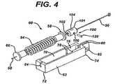
- FIG. 4is an exploded, perspective view of force limiting spring assembly 60 shown in FIG. 2 and FIG. 3 ;
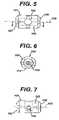
- FIG. 5is a top view of a receiver 101 of mechanical coupling 100 shown in FIG. 3 ;
- FIG. 6is an end view of receiver 101 shown in FIG. 5 ;
- FIG. 7is a side view of receiver 101 shown in FIG. 5 ;
- FIG. 8is a cross-sectional view of receiver 101 shown in FIG. 5 at line 8 - 8 , shown with a tool 130 deforming a wire 50 passing through receiver 101 ;
- FIG. 9is a side view of mechanical coupling 100 assembled onto wire 50 .
- FIG. 1discloses a flexible, endoscopic instrument 10 , also referred to as a medical instrument 10 , having a flexible tube 12 with a distal end 16 and a proximal end 14 .
- Proximal end 14operably attaches to an actuator 18 .
- flexible endoscopic a instrument 10is a clip applier, such as is described in the aforementioned U.S. patent application Ser. No. 10/867501.
- Flexible tube 12can comprise a length of flat wire coil (which can be for example, about 3 mm in diameter by about one meter long) covered with a smooth, plastic outer sheath 8 , as is known in the art for the manufacture of flexible, endoscopic instruments.
- a pair of end effectors 20can be coupled to distal end 16 of flexible tube 12 .
- End effectors 20 and flexible tube 12can be small enough to easily slide through the access channel of a conventional, flexible endoscope from outside the patient to the tissue site inside of the patient.
- Actuator 18can include a frame 26 with a distal end 15 and a proximal end 40 , a stationary grip 28 , and a movable grip 30 .
- movable grip 30is shown in an open position, which for this embodiment corresponds to end effectors 20 being in an open position.
- movable grip 30is shown in a closed configuration, which corresponds to end effectors 20 being in a closed configuration.
- a hook 38can be positioned on movable grip 30 to detachably lock into a latch 39 positioned on stationary grip 28 . Engagement of hook 38 with latch 39 can hold movable grip 30 in the closed position.
- Movable grip 30can include a lever 22 pivotally attached to frame 26 by a lever pivot 32 .
- Actuator 18can include a force limiting spring assembly 60 that is slidably retained in a track 36 of frame 26 .
- a member associated with the spring assembly 60(such as a pin 34 disposed at or near the proximal end of the assembly 60 and which can extend into and engage a surface of slot formed in a clevis of the lever 22 ) can be employed to transfer force from lever 22 to spring assembly 60 , such that spring assembly 60 moves in the proximal direction in track 36 when an operator moves movable grip 30 from the open position in FIG. 1 to the closed position shown in FIG. 2 , and such that spring assembly 60 moves in the distal direction when an operator moves movable grip 30 from the closed position to the open position.
- a control member for transmitting forces from the actuator 18 to the end effectors 20can be in the form of a wire 50 .
- Wire 50can extend through flexible tube 12 .
- Wire 50can have a distal portion which is operatively associated with end effectors 20 , and a proximal portion operatively associated with assembly 60 .
- Wire 50can have a diameter of less than 0.1 inch, and in one embodiment can have a diameter of about 0.024 inches (approximately 0.6 mm) and can be formed of hardened steel.
- a rotation knob 24can be operatively associated with a proximal end of the wire 50 such that an operator may turn a rotation knob 24 in either direction (clockwise or counter clockwise) to cause wire 50 to rotate in a like direction, and thus causing end effectors 20 to rotate in a like direction.
- FIG. 3is an enlarged view of force limiting spring assembly 60 , shown coupled to lever 22 of movable grip 30 .
- a clevis 23 extending from lever 22can include slots 25 for receiving pin 34 .
- a portion of wire 50extends through spring assembly 60 , to be disposed proximally of the assembly 60 .
- Spring assembly 60can include a spring 64 , a mechanical coupling 100 , a proximal end cap 68 , a distal end cap 66 , and a linkage or spring assembly frame 62 .
- Force limiting spring assembly 60can be employed to limit the maximum tensile force imparted to wire 50 by closure of lever 22 , and can assist in preventing accidental damage to end effectors 20 or excessive clamping force on tissue by limiting the maximum tension of wire 50 .
- the tensile load in wire 50reaches a predetermined amount, further closure of lever 22 results in compression of spring 64 converting further movement of movable grip 30 into potential energy stored in spring 64 . This may occur, for example, if the operator clamps end effectors 20 onto excessively thick or hard tissue.
- spring assembly 60allows for variation of the required translation of wire 50 from the open configuration to the closed configuration, and vice versa.
- the required translation of wire 50 to open and close end effectors 20may differ slightly when flexible tube 12 is relatively straight as compared to when flexible tube 12 is curved while positioned in the gastrointestinal tract of the patient. This is because bending of the wound wire coil in flexible tube 12 may cause a slight increase in the effective length of flexible tube 12 along its longitudinal axis, resulting in a small relative movement between wire 50 and flexible tube 12 . Operation of spring assembly is more fully described in the above mentioned U.S. patent application Ser. No. 10/867,501.
- spring assembly frame 62can include a distal end 72 , a proximal end 74 , and a longitudinal axis 52 extending there between.
- Spring assembly frame 62can have an elongated box shape and a smooth finish.
- Spring assembly frame 62may be made from any one of a number of rigid materials, including a metal such as stainless steel or an aluminum alloy, or an injection molded polymer such as a polycarbonate or polyetherimide.
- Spring assembly frame 62can include a spring enclosure 70 for retaining spring 64 , and a mechanical coupling enclosure 76 for retaining mechanical coupling 100 .
- Proximal end 74 of spring assembly frame 62can include a pair of projections in the form of fins 80 projecting proximally from frame 62 . Fins 80 can include holes 82 for receiving pin 34 there through.
- Distal end cap 66can receive the distal end of spring 64 and abut against the inside of distal end 72 of spring assembly frame 62 .
- Proximal end cap 68can receive the proximal end of spring 64 and can bear against a portion of frame 62 (such as a surface of ledge 78 of spring enclosure 70 ) when movable grip 30 is in the open position.
- Spring 64may be loosely retained or partially compressed in spring enclosure 70 , depending on the initial force desired for operating movable grip 30 from the open position.
- Spring 64can be a conventional compression spring preferably made of a corrosion resistant metal such as stainless steel.
- the spring rate of spring 64may vary depending on the requirements of the specific medical application of medical instrument 10 .
- spring 64can be selected to provide a longitudinal force that is approximately equal to the maximum tensile force desired for wire 50 .
- Wire 50passes through a slot 84 in distal end 72 of spring frame 62 and passes through spring frame assembly 60 approximately coaxially with longitudinal axis 52 . Wire 50 slides freely through distal end cap 66 , spring 64 , and proximal end cap 68 during operation.
- Mechanical coupling 100comprises a receiver 101 and a retaining member, which can be in the form of pin 120 . Mechanical coupling 100 can be secured to wire 50 and can abut proximal end cap 68 . When an operator actuates movable grip 30 from the open position to the closed position, longitudinal force of spring 64 bears against mechanical coupling 100 , thus increasing tension of wire 50 .
- Wire 50extends proximally between fins 80 of spring frame 62 to a distal end 51 which can be formed for attachment to rotation knob 24 .
- FIG. 5is a top view
- FIG. 6is an end view
- FIG. 7is a side view of receiver 101 , of mechanical coupling 100 .
- Receiver 101can be made of a relatively rigid material, such as a metal. Suitable metals include but are not limited to brass, aluminum, or stainless steel. Receiver 101 may also be made of a high strength plastic such as 40% glass filled nylon.
- receiver 101is a circular cylinder having a first end 107 , and second end 109 , and a first passageway, such as wire hole 102 extending through receiver 101 from first end 107 to second end 109 along a longitudinal axis 105 .
- the portions of wire hole 102 near first end 107 and second end 109have a larger diameter than the portion of wire hole 102 in the middle portion of receiver 101 to facilitate manufacture and assembly of mechanical coupling 100 .
- Receiver 101can have a smooth, exterior surface 103 , so that receiver 101 may freely translate and rotate about the longitudinal axis of spring assembly 60 (see FIG. 4 .)
- Wire hole 102can be sized such that the diameter of the portion of the wire hole 102 in the middle portion of the receiver 101 is slightly larger than the diameter of wire 50 , thus allowing a close sliding fit for assembly onto wire 50 .
- Receiver 101can also include a second passageway, such as pinhole 106 located approximately midway along the length of receiver 101 .
- Pinhole 106can extend from an outer surface 103 of receiver 101 and be substantially perpendicular to axis 105 .
- Pinhole 106can be positioned to be in intersecting relationship to wire hole 102 .
- Pinhole 106may extend entirely through receiver 101 , as shown in this embodiment, or be a blind hole, and extend only partially through receiver 101 .
- the diameter of pinhole 102can be sized to provide a tight fit for pin 120 ( FIG. 9 ), and may have a nominal diameter, for example, of about 1.5 mm.
- receiver 101can further comprise a third passageway, such as tool hole 104 located approximately midway along the length of receiver 101 .
- Tool hole 104can be substantially perpendicular to longitudinal axis 105 , and substantially perpendicular to pinhole 106 .
- Tool hole 104can have a diameter that is sized to provide a close sliding fit for a tool 130 shown in FIG. 8 .
- Tool hole 104may extend entirely through receiver 101 , or be a blind hole as shown in FIGS. 7 and 8 , extending only partially through receiver 101 .
- Wire hole 102 , tool hole 104 , and pinhole 106can be substantially perpendicular to each other, and can be in intersecting relationship with one another. The longitudinal axes of the holes 102 , 104 and 106 may intersect, but may also be offset from each other.
- FIG. 8shows receiver 101 during one step of a method for assembling mechanical coupling 100 to wire 50 .
- Tool 130may be a steel punch, for example, that is mounted on an arbor press or held by hand and used with a hammer or the like.
- wire 50is positioned at the desired location in wire hole 102
- tool 130is advanced inwardly in hole 104 to deform wire 50 .
- tool 130can be forcefully inserted into tool hole 104 with press, thus deforming wire 50 and resulting in a wire deformation 53 .
- tool hole 104could be formed with internal threads and tool 130 could be in the form of a threaded screw, such that the tool 130 could be threaded into hole 104 to deform wire 50 .
- Tool hole 104may extend into receiver 101 only as deep as required to create wire deformation 53 so that pin 120 may be pressed into pinhole 106 immediately after tool 130 is removed from tool hole 104 .
- the tool hole 104extends beyond the intersection of tool hole 104 and wire hole 102 a distance greater than or equal to the diameter of wire 50 and the diameter of wire hole 102 , so that the deformed portion of wire 50 is displaced a distance greater than or equal to the diameter of the wire 50 , and greater than or equal to the diameter of wire hole 102 .
- tool 130could include a through hole for receiving pin 120 , such that once pin 120 is pressed into pinhole 106 to pass through the hole in tool 130 , the tool 130 would be retained in the receiver 101 by pin 120 .
- Tool hole bottom 111may have a drill point shape, a hemispherical shape, a flat shape, or another shape.
- wire 50is made of hardened spring steel
- receiver 101is made of a softer material such as brass, so that an interface 113 between wire 50 and receiver 101 , located at the intersection of wire hole 102 and tool hole 104 , deforms to help seat wire 50 in receiver 101 .
- a flat 112 on external surface 103serves to help stabilize receiver 101 on a work surface while tool 130 is forcefully inserted into tool hole 104 during assembly of wire 50 to receiver 101 .
- a method for assembling mechanical coupling 100 onto wire 50can include the following steps.
- the assemblerinserts wire 50 through wire hole 102 of receiver 101 and determines a desired longitudinal location of receiver 101 on wire 50 . Determining the desired longitudinal location of receiver 101 on wire 50 may be accomplished, for example, by positioning first end 107 of receiver 101 a predetermined distance from proximal end 14 of flexible tube 12 while end effectors 20 are in a closed position.
- the assemblerthen inserts tool 130 into tool hole 104 to create wire deformation 53 .
- the assemblernext removes tool 130 from tool hole 104 , and immediately presses pin 120 into pinhole 106 of receiver 101 so that pin 120 maintains the deformed configuration of the wire 50 , thus preventing wire deformation 53 from straightening when tension is applied to wire 50 .
- distal end cap 66 , spring 64 , and proximal end cap 68may first be captured onto wire 50 prior to assembling mechanical coupling onto wire 50 to form a subassembly that may then be positioned into spring assembly frame 62 , and finally assembled into actuator 18 .
- Wire deformation 53interlocks with pin 120 such that mechanical coupling 100 may transfer a longitudinal force (tensile or compressive) or a torsional force from actuator 18 to wire 50 .
- end effectors 20require a tensile force in wire 50 to close onto tissue, a compressive force to open, and a torsional force in either direction to rotate in a like direction.
- exterior surface 103 of receiver 101may act as a sliding bearing surface that interfaces with enclosure 76 of spring assembly frame 62 .
- exterior surface 103may act as a rotating bearing surface that interfaces with enclosure 76 and proximal end cap 68 of force limiting assembly 60 .
- a fixturemay be provided that constrains receiver 101 and wire 50 in a desired position during assembly.
- mechanical coupling 100may similarly be assembled onto two or more wires.
- One or more of the wiresmay be sleeved with a short length of tubing.
- two or more wiresmay be enclosed within a short length of tubing, and the length of tubing (together with the wires inside the tubing) can be positioned in the receiver and deformed with the tool 130 .
- control memberis shown as a control wire 50
- other suitable control memberscan be in the form of a strip, tube, rod, cable, or cord that is made of any one or more combinations of various materials including metals, polymers, and natural or synthetic fibers.
Landscapes
- Health & Medical Sciences (AREA)
- Engineering & Computer Science (AREA)
- Life Sciences & Earth Sciences (AREA)
- General Engineering & Computer Science (AREA)
- Surgery (AREA)
- Heart & Thoracic Surgery (AREA)
- Nuclear Medicine, Radiotherapy & Molecular Imaging (AREA)
- Biomedical Technology (AREA)
- Vascular Medicine (AREA)
- Medical Informatics (AREA)
- Molecular Biology (AREA)
- Animal Behavior & Ethology (AREA)
- General Health & Medical Sciences (AREA)
- Public Health (AREA)
- Veterinary Medicine (AREA)
- Reproductive Health (AREA)
- Mechanical Engineering (AREA)
- Surgical Instruments (AREA)
Abstract
Description
Claims (21)
Priority Applications (7)
| Application Number | Priority Date | Filing Date | Title |
|---|---|---|---|
| US11/091,224US7621927B2 (en) | 2005-03-28 | 2005-03-28 | Medical instrument with a mechanical coupling |
| AU2006201237AAU2006201237A1 (en) | 2005-03-28 | 2006-03-24 | Medical instrument with a mechanical coupling |
| JP2006085940AJP2006271975A (en) | 2005-03-28 | 2006-03-27 | Medical apparatus equipped with mechanical connection section |
| CA2541306ACA2541306C (en) | 2005-03-28 | 2006-03-27 | Medical instrument with a mechanical coupling |
| DE602006004629TDE602006004629D1 (en) | 2005-03-28 | 2006-03-27 | Mechanical coupling element between actuating rod and actuating element of a medical instrument |
| EP06251638AEP1707129B1 (en) | 2005-03-28 | 2006-03-27 | Mechanical coupling element between actuating rod and actuator of a medical instrument |
| CNA2006100664012ACN1861009A (en) | 2005-03-28 | 2006-03-28 | Mechanical coupling element between actuating rod and actuator of a medical instrument |
Applications Claiming Priority (1)
| Application Number | Priority Date | Filing Date | Title |
|---|---|---|---|
| US11/091,224US7621927B2 (en) | 2005-03-28 | 2005-03-28 | Medical instrument with a mechanical coupling |
Publications (2)
| Publication Number | Publication Date |
|---|---|
| US20060217743A1 US20060217743A1 (en) | 2006-09-28 |
| US7621927B2true US7621927B2 (en) | 2009-11-24 |
Family
ID=36648864
Family Applications (1)
| Application Number | Title | Priority Date | Filing Date |
|---|---|---|---|
| US11/091,224Active2025-11-22US7621927B2 (en) | 2005-03-28 | 2005-03-28 | Medical instrument with a mechanical coupling |
Country Status (7)
| Country | Link |
|---|---|
| US (1) | US7621927B2 (en) |
| EP (1) | EP1707129B1 (en) |
| JP (1) | JP2006271975A (en) |
| CN (1) | CN1861009A (en) |
| AU (1) | AU2006201237A1 (en) |
| CA (1) | CA2541306C (en) |
| DE (1) | DE602006004629D1 (en) |
Cited By (15)
| Publication number | Priority date | Publication date | Assignee | Title |
|---|---|---|---|---|
| US20150060108A1 (en)* | 2012-03-30 | 2015-03-05 | Gallagher Group Limited | Fence standard |
| US9089379B2 (en) | 2012-07-18 | 2015-07-28 | Jmea Corporation | Multi-impact system for prosthesis deployment device |
| US10004558B2 (en) | 2009-01-12 | 2018-06-26 | Ethicon Endo-Surgery, Inc. | Electrical ablation devices |
| US10105141B2 (en) | 2008-07-14 | 2018-10-23 | Ethicon Endo-Surgery, Inc. | Tissue apposition clip application methods |
| US10206709B2 (en) | 2012-05-14 | 2019-02-19 | Ethicon Llc | Apparatus for introducing an object into a patient |
| US10258406B2 (en) | 2011-02-28 | 2019-04-16 | Ethicon Llc | Electrical ablation devices and methods |
| US10278761B2 (en) | 2011-02-28 | 2019-05-07 | Ethicon Llc | Electrical ablation devices and methods |
| US10314603B2 (en) | 2008-11-25 | 2019-06-11 | Ethicon Llc | Rotational coupling device for surgical instrument with flexible actuators |
| US10342598B2 (en) | 2012-08-15 | 2019-07-09 | Ethicon Llc | Electrosurgical system for delivering a biphasic waveform |
| US10478248B2 (en) | 2007-02-15 | 2019-11-19 | Ethicon Llc | Electroporation ablation apparatus, system, and method |
| US10492880B2 (en) | 2012-07-30 | 2019-12-03 | Ethicon Llc | Needle probe guide |
| US10779882B2 (en) | 2009-10-28 | 2020-09-22 | Ethicon Endo-Surgery, Inc. | Electrical ablation devices |
| US11484191B2 (en) | 2013-02-27 | 2022-11-01 | Cilag Gmbh International | System for performing a minimally invasive surgical procedure |
| US12127889B2 (en) | 2019-07-31 | 2024-10-29 | Conmed Corporation | Force limiting mechanism for surgical instruments |
| US12390258B2 (en) | 2012-07-18 | 2025-08-19 | Jmea Corporation | Methods and apparatus for implanting prostheses |
Families Citing this family (51)
| Publication number | Priority date | Publication date | Assignee | Title |
|---|---|---|---|---|
| US9078650B2 (en)* | 2005-11-23 | 2015-07-14 | Arthrex, Inc. | Handle system for suture driving device |
| US9017345B2 (en)* | 2006-10-06 | 2015-04-28 | Covidien Lp | Coil fastener applier with flexible shaft |
| US7815662B2 (en) | 2007-03-08 | 2010-10-19 | Ethicon Endo-Surgery, Inc. | Surgical suture anchors and deployment device |
| US8075572B2 (en) | 2007-04-26 | 2011-12-13 | Ethicon Endo-Surgery, Inc. | Surgical suturing apparatus |
| US8100922B2 (en) | 2007-04-27 | 2012-01-24 | Ethicon Endo-Surgery, Inc. | Curved needle suturing tool |
| US8579897B2 (en) | 2007-11-21 | 2013-11-12 | Ethicon Endo-Surgery, Inc. | Bipolar forceps |
| US8262655B2 (en) | 2007-11-21 | 2012-09-11 | Ethicon Endo-Surgery, Inc. | Bipolar forceps |
| US8568410B2 (en) | 2007-08-31 | 2013-10-29 | Ethicon Endo-Surgery, Inc. | Electrical ablation surgical instruments |
| US8480657B2 (en) | 2007-10-31 | 2013-07-09 | Ethicon Endo-Surgery, Inc. | Detachable distal overtube section and methods for forming a sealable opening in the wall of an organ |
| US20090112059A1 (en) | 2007-10-31 | 2009-04-30 | Nobis Rudolph H | Apparatus and methods for closing a gastrotomy |
| US8262680B2 (en) | 2008-03-10 | 2012-09-11 | Ethicon Endo-Surgery, Inc. | Anastomotic device |
| US8679003B2 (en) | 2008-05-30 | 2014-03-25 | Ethicon Endo-Surgery, Inc. | Surgical device and endoscope including same |
| US8652150B2 (en) | 2008-05-30 | 2014-02-18 | Ethicon Endo-Surgery, Inc. | Multifunction surgical device |
| US8114072B2 (en) | 2008-05-30 | 2012-02-14 | Ethicon Endo-Surgery, Inc. | Electrical ablation device |
| US8771260B2 (en) | 2008-05-30 | 2014-07-08 | Ethicon Endo-Surgery, Inc. | Actuating and articulating surgical device |
| US8070759B2 (en) | 2008-05-30 | 2011-12-06 | Ethicon Endo-Surgery, Inc. | Surgical fastening device |
| US8317806B2 (en) | 2008-05-30 | 2012-11-27 | Ethicon Endo-Surgery, Inc. | Endoscopic suturing tension controlling and indication devices |
| US8906035B2 (en) | 2008-06-04 | 2014-12-09 | Ethicon Endo-Surgery, Inc. | Endoscopic drop off bag |
| US8403926B2 (en) | 2008-06-05 | 2013-03-26 | Ethicon Endo-Surgery, Inc. | Manually articulating devices |
| US8361112B2 (en) | 2008-06-27 | 2013-01-29 | Ethicon Endo-Surgery, Inc. | Surgical suture arrangement |
| US8357170B2 (en)* | 2008-07-09 | 2013-01-22 | Ethicon Endo-Surgery, Inc. | Devices and methods for placing occlusion fasteners |
| US8262563B2 (en) | 2008-07-14 | 2012-09-11 | Ethicon Endo-Surgery, Inc. | Endoscopic translumenal articulatable steerable overtube |
| US8211125B2 (en) | 2008-08-15 | 2012-07-03 | Ethicon Endo-Surgery, Inc. | Sterile appliance delivery device for endoscopic procedures |
| US8529563B2 (en) | 2008-08-25 | 2013-09-10 | Ethicon Endo-Surgery, Inc. | Electrical ablation devices |
| US8241204B2 (en) | 2008-08-29 | 2012-08-14 | Ethicon Endo-Surgery, Inc. | Articulating end cap |
| US8480689B2 (en) | 2008-09-02 | 2013-07-09 | Ethicon Endo-Surgery, Inc. | Suturing device |
| US8409200B2 (en) | 2008-09-03 | 2013-04-02 | Ethicon Endo-Surgery, Inc. | Surgical grasping device |
| US8114119B2 (en) | 2008-09-09 | 2012-02-14 | Ethicon Endo-Surgery, Inc. | Surgical grasping device |
| US8337394B2 (en) | 2008-10-01 | 2012-12-25 | Ethicon Endo-Surgery, Inc. | Overtube with expandable tip |
| US8172772B2 (en) | 2008-12-11 | 2012-05-08 | Ethicon Endo-Surgery, Inc. | Specimen retrieval device |
| US8828031B2 (en) | 2009-01-12 | 2014-09-09 | Ethicon Endo-Surgery, Inc. | Apparatus for forming an anastomosis |
| US8252057B2 (en) | 2009-01-30 | 2012-08-28 | Ethicon Endo-Surgery, Inc. | Surgical access device |
| US9226772B2 (en) | 2009-01-30 | 2016-01-05 | Ethicon Endo-Surgery, Inc. | Surgical device |
| US8037591B2 (en) | 2009-02-02 | 2011-10-18 | Ethicon Endo-Surgery, Inc. | Surgical scissors |
| US8608652B2 (en) | 2009-11-05 | 2013-12-17 | Ethicon Endo-Surgery, Inc. | Vaginal entry surgical devices, kit, system, and method |
| US8496574B2 (en) | 2009-12-17 | 2013-07-30 | Ethicon Endo-Surgery, Inc. | Selectively positionable camera for surgical guide tube assembly |
| US8353487B2 (en) | 2009-12-17 | 2013-01-15 | Ethicon Endo-Surgery, Inc. | User interface support devices for endoscopic surgical instruments |
| US9028483B2 (en) | 2009-12-18 | 2015-05-12 | Ethicon Endo-Surgery, Inc. | Surgical instrument comprising an electrode |
| US8506564B2 (en) | 2009-12-18 | 2013-08-13 | Ethicon Endo-Surgery, Inc. | Surgical instrument comprising an electrode |
| US9005198B2 (en) | 2010-01-29 | 2015-04-14 | Ethicon Endo-Surgery, Inc. | Surgical instrument comprising an electrode |
| US10092291B2 (en) | 2011-01-25 | 2018-10-09 | Ethicon Endo-Surgery, Inc. | Surgical instrument with selectively rigidizable features |
| US9314620B2 (en) | 2011-02-28 | 2016-04-19 | Ethicon Endo-Surgery, Inc. | Electrical ablation devices and methods |
| US9049987B2 (en) | 2011-03-17 | 2015-06-09 | Ethicon Endo-Surgery, Inc. | Hand held surgical device for manipulating an internal magnet assembly within a patient |
| CN103648414A (en)* | 2011-07-11 | 2014-03-19 | 意昂外科手术有限公司 | Laparoscopic graspers |
| US8986199B2 (en) | 2012-02-17 | 2015-03-24 | Ethicon Endo-Surgery, Inc. | Apparatus and methods for cleaning the lens of an endoscope |
| US9078662B2 (en) | 2012-07-03 | 2015-07-14 | Ethicon Endo-Surgery, Inc. | Endoscopic cap electrode and method for using the same |
| US9572623B2 (en) | 2012-08-02 | 2017-02-21 | Ethicon Endo-Surgery, Inc. | Reusable electrode and disposable sheath |
| US10314649B2 (en) | 2012-08-02 | 2019-06-11 | Ethicon Endo-Surgery, Inc. | Flexible expandable electrode and method of intraluminal delivery of pulsed power |
| CN108135530B (en)* | 2015-10-02 | 2023-01-17 | 皇家飞利浦有限公司 | A hub for device navigation utilizing optical shape-sensing guidewires |
| CN105816208B (en)* | 2016-05-25 | 2018-08-21 | 南京微创医学科技股份有限公司 | A kind of seal wire lock on endoscope |
| WO2018211648A1 (en) | 2017-05-18 | 2018-11-22 | オリンパス株式会社 | Treatment tool |
Citations (8)
| Publication number | Priority date | Publication date | Assignee | Title |
|---|---|---|---|---|
| GB2258028A (en)* | 1991-07-26 | 1993-01-27 | Catton Wire Ind Limited | Automotive cable replacement |
| US5666965A (en)* | 1990-05-10 | 1997-09-16 | Symbiosis Corporation | Radial jaw biopsy forceps |
| US6210398B1 (en)* | 1998-05-28 | 2001-04-03 | Asahi Kogaku Kogyo Kabushiki Kaisha | Manipulating part of endoscopic treatment tool |
| US20010047124A1 (en)* | 2000-05-17 | 2001-11-29 | Olympus Optical Co., Ltd. | Endoscopic instrument |
| US20020038119A1 (en) | 2000-09-26 | 2002-03-28 | Scimed Life Systems, Inc. | Handle assembly for surgical instrument and method of making the assembly |
| US20030191478A1 (en)* | 2001-06-25 | 2003-10-09 | Inscope Development, Llc | Surgical tool having a distal ratchet mechanism |
| US20040143163A1 (en)* | 2003-01-22 | 2004-07-22 | Popcab, Llc | Endoscopic retractor |
| EP1607055A1 (en) | 2004-06-14 | 2005-12-21 | Ethicon Endo-Surgery, Inc. | Endoscopic surgical instrument having a force limiting actuator |
Family Cites Families (1)
| Publication number | Priority date | Publication date | Assignee | Title |
|---|---|---|---|---|
| GB166797A (en)* | 1920-06-10 | 1921-07-28 | George Gale Thomas | Improvements in and connected with bowden wire mechanism |
- 2005
- 2005-03-28USUS11/091,224patent/US7621927B2/enactiveActive
- 2006
- 2006-03-24AUAU2006201237Apatent/AU2006201237A1/ennot_activeAbandoned
- 2006-03-27EPEP06251638Apatent/EP1707129B1/ennot_activeCeased
- 2006-03-27CACA2541306Apatent/CA2541306C/ennot_activeExpired - Fee Related
- 2006-03-27DEDE602006004629Tpatent/DE602006004629D1/enactiveActive
- 2006-03-27JPJP2006085940Apatent/JP2006271975A/enactivePending
- 2006-03-28CNCNA2006100664012Apatent/CN1861009A/enactivePending
Patent Citations (8)
| Publication number | Priority date | Publication date | Assignee | Title |
|---|---|---|---|---|
| US5666965A (en)* | 1990-05-10 | 1997-09-16 | Symbiosis Corporation | Radial jaw biopsy forceps |
| GB2258028A (en)* | 1991-07-26 | 1993-01-27 | Catton Wire Ind Limited | Automotive cable replacement |
| US6210398B1 (en)* | 1998-05-28 | 2001-04-03 | Asahi Kogaku Kogyo Kabushiki Kaisha | Manipulating part of endoscopic treatment tool |
| US20010047124A1 (en)* | 2000-05-17 | 2001-11-29 | Olympus Optical Co., Ltd. | Endoscopic instrument |
| US20020038119A1 (en) | 2000-09-26 | 2002-03-28 | Scimed Life Systems, Inc. | Handle assembly for surgical instrument and method of making the assembly |
| US20030191478A1 (en)* | 2001-06-25 | 2003-10-09 | Inscope Development, Llc | Surgical tool having a distal ratchet mechanism |
| US20040143163A1 (en)* | 2003-01-22 | 2004-07-22 | Popcab, Llc | Endoscopic retractor |
| EP1607055A1 (en) | 2004-06-14 | 2005-12-21 | Ethicon Endo-Surgery, Inc. | Endoscopic surgical instrument having a force limiting actuator |
Non-Patent Citations (1)
| Title |
|---|
| EPO Search Report dated Jul. 17, 2006 for corresponding patent application, European Patent Application No. 06251638. |
Cited By (24)
| Publication number | Priority date | Publication date | Assignee | Title |
|---|---|---|---|---|
| US10478248B2 (en) | 2007-02-15 | 2019-11-19 | Ethicon Llc | Electroporation ablation apparatus, system, and method |
| US10105141B2 (en) | 2008-07-14 | 2018-10-23 | Ethicon Endo-Surgery, Inc. | Tissue apposition clip application methods |
| US11399834B2 (en) | 2008-07-14 | 2022-08-02 | Cilag Gmbh International | Tissue apposition clip application methods |
| US10314603B2 (en) | 2008-11-25 | 2019-06-11 | Ethicon Llc | Rotational coupling device for surgical instrument with flexible actuators |
| US10004558B2 (en) | 2009-01-12 | 2018-06-26 | Ethicon Endo-Surgery, Inc. | Electrical ablation devices |
| US10779882B2 (en) | 2009-10-28 | 2020-09-22 | Ethicon Endo-Surgery, Inc. | Electrical ablation devices |
| US10258406B2 (en) | 2011-02-28 | 2019-04-16 | Ethicon Llc | Electrical ablation devices and methods |
| US10278761B2 (en) | 2011-02-28 | 2019-05-07 | Ethicon Llc | Electrical ablation devices and methods |
| US20150060108A1 (en)* | 2012-03-30 | 2015-03-05 | Gallagher Group Limited | Fence standard |
| US10170221B2 (en)* | 2012-03-30 | 2019-01-01 | Gallagher Group Limited | Fence standard |
| US10206709B2 (en) | 2012-05-14 | 2019-02-19 | Ethicon Llc | Apparatus for introducing an object into a patient |
| US11284918B2 (en) | 2012-05-14 | 2022-03-29 | Cilag GmbH Inlernational | Apparatus for introducing a steerable camera assembly into a patient |
| US9463009B2 (en) | 2012-07-18 | 2016-10-11 | Jmea Corporation | Expandable prosthesis for a tissue repair system |
| US9198704B2 (en) | 2012-07-18 | 2015-12-01 | Jmea Corporation | Impact and drive system for prosthesis deployment device |
| US10660686B2 (en) | 2012-07-18 | 2020-05-26 | Jmea Corporation | Methods and apparatus for implanting prostheses |
| US9572615B2 (en) | 2012-07-18 | 2017-02-21 | Jmea Corporation | Detachable front delivery assembly for a tissue repair system |
| US9433456B2 (en) | 2012-07-18 | 2016-09-06 | Jmea Corporation | Method and system for implanting multiple prostheses |
| US9089379B2 (en) | 2012-07-18 | 2015-07-28 | Jmea Corporation | Multi-impact system for prosthesis deployment device |
| US11882988B2 (en) | 2012-07-18 | 2024-01-30 | Jmea Corporation | Methods and apparatus for implanting prostheses |
| US12390258B2 (en) | 2012-07-18 | 2025-08-19 | Jmea Corporation | Methods and apparatus for implanting prostheses |
| US10492880B2 (en) | 2012-07-30 | 2019-12-03 | Ethicon Llc | Needle probe guide |
| US10342598B2 (en) | 2012-08-15 | 2019-07-09 | Ethicon Llc | Electrosurgical system for delivering a biphasic waveform |
| US11484191B2 (en) | 2013-02-27 | 2022-11-01 | Cilag Gmbh International | System for performing a minimally invasive surgical procedure |
| US12127889B2 (en) | 2019-07-31 | 2024-10-29 | Conmed Corporation | Force limiting mechanism for surgical instruments |
Also Published As
| Publication number | Publication date |
|---|---|
| CN1861009A (en) | 2006-11-15 |
| JP2006271975A (en) | 2006-10-12 |
| CA2541306A1 (en) | 2006-09-28 |
| US20060217743A1 (en) | 2006-09-28 |
| EP1707129B1 (en) | 2009-01-07 |
| DE602006004629D1 (en) | 2009-02-26 |
| AU2006201237A1 (en) | 2006-10-12 |
| CA2541306C (en) | 2014-02-25 |
| EP1707129A1 (en) | 2006-10-04 |
Similar Documents
| Publication | Publication Date | Title |
|---|---|---|
| US7621927B2 (en) | Medical instrument with a mechanical coupling | |
| US20060217742A1 (en) | Mechanical coupling method | |
| US7357806B2 (en) | Clip ejector for endoscopic clip applier | |
| US8216255B2 (en) | Endoscopic clip applier actuator | |
| US6605077B2 (en) | Snap handle assembly for an endoscopic instrument | |
| JP4522732B2 (en) | Surgical instruments, surgical clip appliers, and clip applier instruments | |
| JP4498788B2 (en) | Jaw assembly, end effector assembly, endoscopic surgical instrument, and endoscopic assembly | |
| US7615058B2 (en) | Surgical clip applier having jaws adapted to guide and deform a clip | |
| CN100571640C (en) | Force limiting mechanism for medical instruments | |
| US5478350A (en) | Rack and pinion actuator handle for endoscopic instruments | |
| US20010034536A1 (en) | Surgical device with malleable shaft | |
| CA2517468A1 (en) | Surgical device with malleable shaft | |
| CA2194775A1 (en) | Track guided end effector assembly |
Legal Events
| Date | Code | Title | Description |
|---|---|---|---|
| AS | Assignment | Owner name:ETHICON ENDO-SURGERY, INC., OHIO Free format text:ASSIGNMENT OF ASSIGNORS INTEREST;ASSIGNORS:MESSERLY, JEFFREY D.;JAMISON, BARRY T.;SMOLIK, STEVEN P.;REEL/FRAME:016422/0621 Effective date:20050325 | |
| STCF | Information on status: patent grant | Free format text:PATENTED CASE | |
| FPAY | Fee payment | Year of fee payment:4 | |
| AS | Assignment | Owner name:ETHICON ENDO-SURGERY, LLC, PUERTO RICO Free format text:ASSIGNMENT OF ASSIGNORS INTEREST;ASSIGNOR:ETHICON ENDO-SURGERY, INC.;REEL/FRAME:037161/0276 Effective date:20151106 | |
| AS | Assignment | Owner name:ETHICON LLC, PUERTO RICO Free format text:CHANGE OF NAME;ASSIGNOR:ETHICON ENDO-SURGERY, LLC;REEL/FRAME:041821/0186 Effective date:20161230 | |
| FPAY | Fee payment | Year of fee payment:8 | |
| AS | Assignment | Owner name:CILAG GMBH INTERNATIONAL, SWITZERLAND Free format text:ASSIGNMENT OF ASSIGNORS INTEREST;ASSIGNOR:ETHICON LLC;REEL/FRAME:056601/0339 Effective date:20210405 | |
| MAFP | Maintenance fee payment | Free format text:PAYMENT OF MAINTENANCE FEE, 12TH YEAR, LARGE ENTITY (ORIGINAL EVENT CODE: M1553); ENTITY STATUS OF PATENT OWNER: LARGE ENTITY Year of fee payment:12 |