US7621926B2 - Multi-fire surgical clip applier - Google Patents
Multi-fire surgical clip applierDownload PDFInfo
- Publication number
- US7621926B2 US7621926B2US10/962,093US96209304AUS7621926B2US 7621926 B2US7621926 B2US 7621926B2US 96209304 AUS96209304 AUS 96209304AUS 7621926 B2US7621926 B2US 7621926B2
- Authority
- US
- United States
- Prior art keywords
- rack
- clip
- applier
- closure member
- feeder
- Prior art date
- Legal status (The legal status is an assumption and is not a legal conclusion. Google has not performed a legal analysis and makes no representation as to the accuracy of the status listed.)
- Expired - Fee Related, expires
Links
Images


Classifications
- A—HUMAN NECESSITIES
- A61—MEDICAL OR VETERINARY SCIENCE; HYGIENE
- A61B—DIAGNOSIS; SURGERY; IDENTIFICATION
- A61B17/00—Surgical instruments, devices or methods
- A61B17/12—Surgical instruments, devices or methods for ligaturing or otherwise compressing tubular parts of the body, e.g. blood vessels or umbilical cord
- A61B17/128—Surgical instruments, devices or methods for ligaturing or otherwise compressing tubular parts of the body, e.g. blood vessels or umbilical cord for applying or removing clamps or clips
- A61B17/1285—Surgical instruments, devices or methods for ligaturing or otherwise compressing tubular parts of the body, e.g. blood vessels or umbilical cord for applying or removing clamps or clips for minimally invasive surgery
- A—HUMAN NECESSITIES
- A61—MEDICAL OR VETERINARY SCIENCE; HYGIENE
- A61B—DIAGNOSIS; SURGERY; IDENTIFICATION
- A61B17/00—Surgical instruments, devices or methods
- A61B17/12—Surgical instruments, devices or methods for ligaturing or otherwise compressing tubular parts of the body, e.g. blood vessels or umbilical cord
- A61B17/128—Surgical instruments, devices or methods for ligaturing or otherwise compressing tubular parts of the body, e.g. blood vessels or umbilical cord for applying or removing clamps or clips
- A—HUMAN NECESSITIES
- A61—MEDICAL OR VETERINARY SCIENCE; HYGIENE
- A61B—DIAGNOSIS; SURGERY; IDENTIFICATION
- A61B17/00—Surgical instruments, devices or methods
- A61B2017/00367—Details of actuation of instruments, e.g. relations between pushing buttons, or the like, and activation of the tool, working tip, or the like
- A61B2017/00407—Ratchet means
- A—HUMAN NECESSITIES
- A61—MEDICAL OR VETERINARY SCIENCE; HYGIENE
- A61B—DIAGNOSIS; SURGERY; IDENTIFICATION
- A61B17/00—Surgical instruments, devices or methods
- A61B2017/0046—Surgical instruments, devices or methods with a releasable handle; with handle and operating part separable
Definitions
- the present inventionrelates generally to surgical instruments and, more to particularly, to fully controllable multi-fire clip appliers.
- Clip appliersare frequently used in endoscopic, laparoscopic and other surgeries related to the use of a trocar or a small entry incision for the application of hemostatic clips.
- a clipis placed between the jaw of a clip applier to be crimped onto a vessel, tissue or an object, such as another clip.
- Some clip appliershave difficulty in placing the clips reliably and properly between the jaw to promote crimping and avoid clips from jamming before reaching the jaw.
- Clip appliershaving the characteristics of simplicity in construction, reliability in operation and sufficiently economical to allow reusability or disposability are also hard to achieve. Complicated mechanical components or assemblies of a clip applier can also be expensive to produce, complex to manufacture and difficult to sterilize.
- Tactile feedback provided to the surgeon or user and instrument operationshould also be natural and comfortable thereby avoiding undue, obtrusive or wasted motions or force applied to or by the instrument.
- a clip applieris provided to ensure that the jaw is sufficiently open prior to moving a clip into the jaw.
- the clip applierin one embodiment of the present invention ensures the timing of opening the jaw corresponds to moving a clip into the jaw. Components, assemblies or mechanisms used to accomplish this are simplified to reduce costs and difficulties in manufacturing, assembly, reliability and sterilization.
- mechanisms to open the jawinteract with mechanisms to move a clip into the jaw to provide simultaneous movement of these mechanisms throughout operation of the clip applier and/or no additional force or components are used on racks associated with these mechanisms.
- a clip applier applying a surgical clipcomprises a cartridge with a proximal end and a distal end and an actuator.
- the cartridgeincludes a feeder having a proximal end and a distal end, a rack mechanism, a closure member having a proximal end and a distal end, and a pair of opposing crimping members extending outwardly from the distal end of the closure member.
- the rack mechanismhas a spur gear, a first rack connected to the feeder, and a second rack connected to the closure member.
- the actuatorcoupled to the proximal end of the cartridge and the proximal end of the closure member.
- the actuatoris arranged to open the opposing crimping members during an opening stroke.
- the closure member and the second rackare arranged to move synchronously throughout the opening stroke.
- a clip applier applying a surgical clipcomprises a cartridge and a closure member.
- the cartridge with a proximal end and a distal endincludes a feeder having a proximal end and a distal end, a closure member having a proximal end and a distal end, a pair of opposing crimping members extending outwardly from the distal end of the closure member, and a rack mechanism.
- the rack mechanismhas a spur gear, a first rack connected to the feeder, and a second rack directly connected to the closure member.
- the closure member and the second rackare only movable together.
- the actuatoris coupled to the proximal end of the cartridge and the proximal end of the closure member.
- a method of applying a surgical clip having crimping members coupled to a closure member coupled to a feederprovides extending a feeder of a clip applier to move a clip into crimping members of a clip applier, extending a closure member of the clip applier to close the crimping members and the clip over an object to be clipped, and retracting the feeder of the clip applier simultaneously and continuously while the closure member is extending and until the closure member closes the crimping members.
- the closure memberis retracted to open the crimping members to release the clip and the feeder of the clip applier is extended simultaneously and continuously while the closure member is retracting and until the closure member fully opens the crimping members.
- a method of manufacturing a jaw of a clip applierprovides grinding a side profile of a jaw into a plate and machining the plate to form an entry point for clips on a proximal end of the jaw. The method further provides machining the plate to form grooves for clips along an inner surface of each crimping member of the jaw up to substantially near a distal end of the jaw, hardening the plate, and cutting a top profile of the jaw by using an electrical discharge machine.
- Another method of manufacturing a jaw of a clip applier in yet another aspect of the present inventionprovides hardening a steel block, cutting at least one top profile of at least one jaw into the block, and leaving the at least one jaw attached in a rear portion to a portion of the block using an electrical discharge machine.
- the methodfurther provides patterning a shape of interior grooves in the at least one jaw, burning the pattern into the at least one jaw using the electrical discharge machine, and detaching the jaw from the block using the electrical discharge machine.
- a clip applieris utilized for ligating and occluding various sized vessels, other tissues or a previously applied clip or object and is capable of inserting a surgical clip through a cannula while minimizing the width or diameter occupied by the applier.
- a surgical clipin one aspect, is generally U-shaped or V-shaped with a pair of outwardly extending and generally opposed legs connected at an apex.
- FIG. 1illustrates a clip applier having a cartridge and an actuator in accordance with one embodiment of the present invention
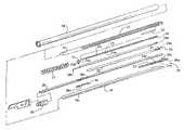
- FIG. 2Aillustrates an exploded view showing the assembly of the components of or connected to the cartridge
- FIG. 2Billustrates a perspective view of one embodiment of a jaw
- FIG. 3illustrates an exploded view showing one embodiment of a rack mechanism in the cartridge
- FIGS. 4A-4Billustrate one embodiment of an actuator
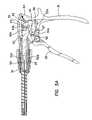
- FIGS. 5A-5Billustrate another embodiment of an actuator
- FIGS. 6A-6Billustrate embodiments of an assembled actuator of FIGS. 5A-5B ;
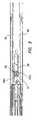
- FIG. 7Aillustrates a cross sectional view of one embodiment of the cartridge
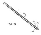
- FIG. 7Billustrates one embodiment of a partially assembled cartridge
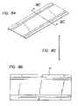
- FIGS. 8A-Cillustrate one embodiment of a plate used for manufacturing an embodiment of a jaw or jaws of the present invention
- FIG. 9illustrates one embodiment of jaws being formed from a plate in accordance with one aspect of the present invention.
- FIGS. 10A-Cillustrate one embodiment of jaws being formed from a steel block in accordance with one aspect of the present invention.
- FIG. 1a laparoscopic clip applier 10 in accordance with one embodiment of the present invention is shown.
- the clip applier 10is useful for endoscopic or a minimally invasive surgery.
- Clip applier 10includes a disposable cartridge 12 and an actuator 14 connected to the disposable cartridge 12 .
- the clip applier 10in one embodiment, utilizes a two-way ratchet mechanism without delay and maintains a simplified construction in both the cartridge 12 and actuator 14 .
- the clip applier 10 containing fewer partsis easier to sterilize and is less expensive to produce.
- the clip applier 10being partly or fully disposable, in another embodiment, the cartridge 12 and/or the actuator 14 do not need to be constructed of long lasting materials.
- a userin operating the clip applier 10 , a user completes a full actuating stroke advancing trigger 13 towards handle 15 of actuator 14 until a ratchet engagement releases and trigger 13 is allowed to return to its original position without impediment.
- the ratchet engagementwill be described later in greater detail below.
- a useris permitted to release a partially crimped clip, if desired, or release a fully crimped clip.
- the clip applierAfter release of a clip and once the engagement is re-engaged, the clip applier returns to its original position before another full actuating stroke can be performed. As such, the negative effects of unintended clip application, e.g., improper clip closing, clip releasing or clip feeding, are reduced.
- the actuator 14also includes a collar 17 .
- the collar 17is rotatable about the actuator 14 that allows the position of disposable cartridge 12 to be reoriented as desired during use.
- cantilever armsextending from collar 17 engaging slots in the cartridge 12 or a frictional engagement of the collar 17 with the cartridge 12 , a rotational force applied to collar 17 is transmitted to cartridge 12 thereby rotating cartridge 12 .
- FIGS. 2-7illustrate further features of construction and operation of the clip applier 10 .
- cartridge 12includes a cover tube 16 that holds bottom housing 18 and a top cartridge 20 .
- a pusher spring 22is connected at its distal end to top cartridge 20 and at its proximal end to a pusher 24 .
- the proximal end of pusher 24has a pushing surface 24 a that conforms to a clip 26 .
- a series of clips 26can be stacked end-to-end in front of pushing surface 24 a ; however, it is viewed that the scope of the invention is broad enough to include a cartridge that applies one or more clips in sequence.
- a last clip follower 23in one embodiment, is slidably mounted to the pusher 24 .
- the distal end of the last clip follower 23conforms to a clip 26 and the proximal end conforms to the pushing surface 24 a .
- An extension memberextends from an apex portion of the proximal end of the last clip follower along a channel in the pusher 24 .
- a tabextends perpendicularly from the extension member through a slot in the pusher 24 .
- the pusher 24traverses distally due to pusher spring 22 and as clips 26 are applied, the pusher and last clip follower moves closer to the distal end of the cartridge 12 .
- the last clip follower being mounted on the pusher 24is prevented from being fed for application.
- the slot in the pusher 24allows the last clip follower to continue to travel distally. Until contact is made by the tab on the last clip follower on the distal end of the slot, the last clip follower continues to travel and thereby prevents the last clip follower from jamming the cartridge after the last clip is expended.
- Clips 26rest on a feeder 28 as does pusher 24 while feeder 28 rests on cartridge floor 32 .
- the distal end of feeder 28comprises a feeder surface 28 b that, similar to pushing surface 24 a, conforms to the shape or an apex portion of a clip 26 to further advance the clips.
- the cartridge floor 32includes a finger 21 that holds the next clip to be fed in place while the current clip is fed distally to jaw 30 .
- the floor 32also includes a clip stop 35 that prevents the current clip from retreating back into the cartridge 12 from jaw 30 .
- the jaw 30 disposed partially in the cartridge 12has a pair of opposed tapered surfaces 34 a and 34 b at the distal end of an elongated slot 33 .
- Mounted or extending distally to tapered surfaces 34 a and 34 bare jaw members or crimping members 38 a and 38 b , respectively.
- Jaw 30is mounted onto posts extending from bottom housing 18 .
- the crimping members 38 a and 38 binclude jaw tips ( FIG. 2B ) that are “bone shaped” to allow for better clip closure and visualization of the clip in the jaw 30 .
- Better clip closurein one embodiment, is achieved by thinning out the jaw tips allowing them to flex. This flexing allows for full compression of the clip apex.
- the thin jaw tipsreduces resistance to movement of the crimping members together and thereby maximizes the force by the closure member to move the crimping members 38 a and 38 b together.
- the jaw tipsinclude rounded protrusions or bumps. The bumps are at the distal end of the tips and make the jaw a-traumatic, preventing potential damage to tissue and trocar seals.
- Closure member 36is mounted over jaw 30 . Tapered surfaces 34 a and 34 b , however, extend through a distal opening in closure member 36 . Closure member 36 is also mounted between bottom housing 18 and top cartridge 20 and translates longitudinally responsive to a force input communicated by actuator 14 . Jaw 30 opens as the actuator 14 is relaxed enough to allow backward travel of the closure member 36 . This arrangement is desirable for a user demanding ultimate control of clip closure, e.g., affecting a partially closed or fully closed clip, and clip release once a clip is at least partially closed.
- the rack 28 aExtending from the proximal end of feeder 28 is rack 28 a .
- the rack 28 ahas a plurality of teeth that extend laterally from rack 28 a and thus the feeder 28 is operatively connected to a top portion 29 a of spur gear 29 .
- a bottom portion 29 b of spur gear 29is smaller than the top portion 29 a of the spur gear 29 , in one aspect of the present invention.
- the bottom portion 29 b of spur gear 29engages a plurality of teeth on closure rack 39 .
- the teeth on rack 39 extending laterally from rack 39are in an opposite direction from that of the teeth on rack 28 a .
- Rack 39further includes two posts extending from either ends of the rack. Each post extends through an opening in closure member 36 to directly connect rack 39 to closure member 36 .
- a slot 36 a in closure member 36exposes rack 39 for permitting the bottom portion 29 b of spur gear 29 to engage the teeth of rack 39 .
- a hemispherical trough 18 ais disposed in bottom housing 18 that receives a corresponding hemispherical tab 39 a that substantially extends along the length of rack 39 .
- rack 39slides along the trough 18 a .
- Spring 37surrounds a proximal portion of closure member 36 and is limited from moving distally by a tab on closure member 36 .
- the spur gear 29is a compound gear that is two gears parallel to each other supported by spindle 31 .
- the diameters and the number of teeth on each gear or upper and lower portions of the gearare different.
- the ratio of teeth and diameters of the gears or portions of the gearsdetermine the degree of movement of the closure member 36 and feeder 28 . Varying the ratio of teeth and diameters of the gears or portions of the gears may also accommodate different sized clips.
- teeth of rack 28 aengage substantially in the same plane with upper portion 29 a of spur gear 29 .
- lower gear or lower portion 29 b of spur gear 29engages substantially in the same plane with the teeth of rack 39 .
- Teeth of rack 28 aface teeth of rack 39 on opposite sides of a longitudinal axis through cartridge 12 with teeth of rack 28 a being in a higher plane than teeth of rack 39 .
- one end of spindle 31 of spur gear 29extends through an opening in a cover housing 19 .
- the other end of spindle 31extends through an opening in the bottom housing 18 .
- the cover housing 19is mounted on the proximal end of the bottom housing 18 via tabs on the bottom housing 18 inserted into corresponding recesses on the cover housing 19 .
- the cover housing 19 and the bottom housing 18secure the spindle 31 of the spur gear 29 , but do not inhibit the rotation of the spur gear 29 .
- accurate placement of the spur gear 29 to engage the rack 28 a extending from feeder 28 and the rack 39is facilitated, as is cartridge assembly.
- FIGS. 4A-4Bone embodiment of actuator 14 ( FIG. 1 ), and in one embodiment a disposable actuator, is shown.
- the proximal end of closure member 36is connected to plunger 25 through a slot in the cylindrical portion of the plunger.
- a pinis inserted through the plunger 25 and closure member 36 to further secure the plunger 25 to the closure member 36 .
- Plunger 25biases spring 37 from moving proximally.
- both the plunger 25 and the spring 37are inserted through an opening in the actuator 14 and the collar 17 ( FIG. 1 ). In operation, as force is applied to plunger 25 , plunger 25 compresses spring 37 and causes closure member 36 to move longitudinally towards the distal end of the cartridge 12 .
- the proximal end of plunger 25includes a circular notch 26 connected to driver 40 by arms 40 a and 40 b for permitting rotational movement of cartridge 12 as well as longitudinal movement of closure member 36 by driver 40 .
- a circular tab 16 a on the proximal end of tube 16is confined in a slot formed in the actuator 14 and defines a diameter larger than the opening of collar 17 or actuator 14 and prevents longitudinal distal movement of tube 16 .
- Actuator 14also includes trigger 13 and handle 15 .
- Trigger 13is connected to a post 15 a on handle 15 . When actuated, trigger 13 pivots around post 15 a .
- Driver 40rests between split tabs 13 a and 13 b (not shown) that extend from trigger 13 .
- Pin 44extends through a slot in split tab 13 a , a hole in driver 39 and a corresponding slot in split tab 13 b and is received into a slot on handle 15 to slidably connect driver 40 to the handle 15 .
- a handle coveralso has a corresponding slot to receive pin 44 and to slidably connect driver 40 to the handle cover.
- multiple apertures or posts on handle 15 able to receive respective posts or apertures on the corresponding handle coverprovide for a snap fitting engagement of the handle 15 to the handle cover.
- driver 40includes a rack region 41 having teeth that operatively engages pawl 42 .
- Pawl 42has three teeth. The middle tooth of pawl 42 extends further than the adjacent side teeth.
- a spring 43 on one endis connected to the pawl 42 and on the other end is connected to a post extending from the handle 15 .
- a pivot pinextends through the center of pawl 42 and is inserted into corresponding apertures on handle 15 and the handle cover.
- driver 40moves in the distal direction that causes pawl 42 to pivot and engage the teeth of rack region 41 .
- Spring 43biases pawl 42 to force pawl 42 securely into the teeth of rack region 41 .
- This engagementin particular, the middle tooth and one of the side teeth, the tooth on the side opposite to the travel direction of driver 40 , with the rack region 41 , permits distal movement of the driver 40 but prevents proximal movement of the driver 40 .
- the spring 43causes pawl 42 to pivot to a substantially upright position.
- Spring 37compresses as the driver is moved distally, as previously described, and thus upon release of trigger 13 , i.e., trigger 13 moves away from handle 15 , spring 37 causes driver 40 to move proximally.
- Driver 40 traveling backcauses pawl 42 to pivot and engage the teeth of rack region 41 .
- Spring 43biases pawl 42 to force pawl 42 securely into the teeth of rack region 41 to permit proximal movement of driver 40 but prevents distal movement of the driver 40 until pawl 42 once again disengages the rack region 41 .
- driver 40when the trigger 13 is released, spring 37 will cause driver 40 to return to its original position without delay once pawl 42 first disengages the rack region 41 .
- the rate at which driver 40 travels back distallymay be controlled by the amount of force or pressure exerted on trigger 13 as the trigger 13 is released. The operation and affect of the actuator 14 regarding clip feeding and clamping will be described later in greater detail below.
- FIGS. 5A-5Banother embodiment of actuator 14 of the present invention having a dual pivot cam mechanism is shown.
- the cam mechanismincludes trigger 50 connected to pivot link 53 .
- Rotational motion of trigger 50 rotating about post 55 on handle 51is transmitted to pivot link 53 via pin 56 .
- Pin 56 connected to the proximal end of trigger 50is disposed within a slot 53 a on pivot link 53 .
- Pivot link 53subsequently rotates about pin 57 that extends through opening 50 a in trigger 50 and is connected to pivot link 53 and handle 51 .
- pivot link 53is connected to driver 52 via pin 54 extending through an aperture 53 b of pivot link 53 , rotational motion of trigger 50 and pivot link 53 causes driver 52 to move linearly.
- Post 55a first pivot point, provides a natural or a comfortable stroke for advancing the trigger 50 towards handle 51 .
- Pivot link 53 pivoting on pin 57a second pivot point, shortens the rotational travel used to move driver 52 while still communicating the force on driver 52 as expected based on the actuation of trigger 50 .
- the reduction of rotational travelminimizes the space utilized by the cam mechanism to move driver 52 . Therefore, by providing two pivot points, a user may comfortably move the actuator without requiring additional force or losing any mechanical advantage and still permit a compact cam mechanism so that additional space in the actuator or a larger actuator is not required.
- Driver 52in one embodiment, includes two arms 52 a and 52 b (not shown) for connecting to pivot link 53 .
- Pivot link 53rests in a crevice defined between the two arms 52 a and 52 b .
- Pin 54inserted through holes in arms 52 a and 52 b and an aperture 53 b in pivot link 53 further secures the driver 52 to pivot link 53 .
- Arms 52 c and 52 d on the distal end of driver 52connect to a cylindrical notch in plunger 25 to interlock the driver 52 and plunger 25 . Through this interlock, linear motion of driver 52 is communicated to plunger 25 and vice versa. However, rotational motion of the plunger 25 and in particular cartridge 12 ( FIG. 1 ) that may occur during clip application is not communicated to driver 52 .
- Plunger 25 moving distallyalso compresses spring 37 ( FIG. 2A ) and in turn distally moves closure member 36 .
- Pin 59secures plunger 25 to closure member 36 .
- Pivot link 53includes a rack region 61 having teeth that operatively engages pawl 62 rotatably mounted on a pivot pin inserted into handle 51 .
- Spring 63operationally biases pawl 62 to force pawl 62 securely into the teeth of rack region 61 .
- the middle tooth and one of the side teeth of pawl 62permits distal linear movement of driver 52 and counter clockwise motion of pivot link 53 but prevents proximal linear movement of the driver 52 and clockwise motion of pivot link 53 .
- Rack region 61in one aspect of the present invention, may extend substantially along the surface area of pivot link 53 without operationally affecting the manipulation of actuator 14 .
- An increased rack region 61allows for an increase in spacing or size of the teeth of rack region 61 that eases sterilization of the actuator 14 and in particular rack region 61 .
- Actuator 14further includes a swing cover 66 as shown in FIGS. 6A-6B .
- the handle 51is a single component housing portions of the trigger, the pivot link and other previously mentioned components.
- the handlecomprises a handle cover mounted onto a handle housing in which portions of the trigger, the pivot link and other previously mentioned components are disposed there between.
- Swing cover 66rotatably connected to handle 51 protects the driver 52 and other components of the cam mechanism within a cavity disposed in swing cover 66 .
- Swing cover 66specifically, rotates about pin 67 and snaps onto a cylindrical boss 68 . Swing cover 66 may also be rotated clockwise to expose the driver 52 and other components of the cam mechanism to facilitate sterilization of the actuator 14 .
- the cartridge 12is longitudinally inserted into and connected to the actuator 14 .
- a longitudinal component of an L-shaped slot or slots on the actuatorpasses by a pin or pins mounted on a cuff on the cartridge in which a spring disposed in the cuff compresses.
- the cartridge 12is rotated to move the pin or pins along the radial component(s) of the L shaped slot or slots and the cuff spring is allowed to extend such that the cartridge is thereby secured to the actuator.
- a slide cuffmay also be slidably connected to the actuator 14 and connected to the collar 17 for retracting to expose the slot or slots on the actuator 14 and for extending to cover and protect the fitting.
- the collar 17acts as a slide cuff.
- one or more extension membersmay be disposed between the actuator 14 and the cartridge 12 to extend the reach of the clip applier 10 .
- the extension membersmay be similarly fitted as described above to the actuator or cartridge.
- a rodis disposed in the extension member for communicating force applied by the actuator or from the cartridge.
- the rodinteracts with spring 37 ( FIG. 2A ) and includes a slot for receiving closure member 36 .
- closure member 36traverses distally.
- rack 39 connected to the closure member 36also moves in the distal direction.
- the teeth of rack 39engage the lower portion 29 b of spur gear 29 to rotate spur gear 29 .
- the upper portion 29 b of the spur gear 29also rotates and engages the teeth of rack 28 a extending from feeder 28 thereby causing feeder 28 to travel in the proximal direction or retract.
- a clip placed between crimping members or jaws 38 a and 38 bis also crimped as jaws 38 a and 38 b move toward each other.
- a surgeon by actuating the triggeris in direct or full control of the crimping of the clip.
- the ratchet mechanisme.g., the pawl 42 and rack 41 or the pawl 62 and rack region 61 , in actuator 14 engage to permit continued pressure on trigger 13 while maintaining the position of the trigger if pressure is removed or reduced.
- the cartridge floor 32includes a finger 21 with a peninsular cutout 21 b ( FIG. 2 ) and a portion angled 21 a towards the top cartridge 20 .
- Finger 21along with side ramps 71 a and 71 b and middle ramp 71 c of top cartridge 20 holds the next clip in position in preparation for feeder surface 28 b on feeder 28 to contact the clip.
- the finger 21in one embodiment, travels along a groove extending through the center portion of the feeder 28 as the feeder is extended and retracted to prevent interference of the finger 21 with the feeder 28 and yet maintain maximum retention of the next clip.
- the feeder 28extends due to the rack mechanism in the cartridge 12 , e.g., rack 39 , rack 28 a , and the spur gear 29 now rotating in the opposite direction.
- Feeder surface 28 b of feeder 28contacts the next clip to move it distally guided by finger 21 .
- the arms of the next clipmove along the sides of finger 21 and contact with the bight portion of the next clip causes the finger 21 to flex towards the bottom housing 18 .
- uneven contact or force applied by the feeder surface 28 b of feeder 28 or a skewed position of the next clipis counter balanced by the peninsular cutout and angled portion of finger 21 . Therefore, misalignment of the next clip is reduced as it is guided towards the crimping members 38 a and 38 b of jaw 30 .
- the clipclears the side ramps 71 a and 71 b of top cartridge 20 , finger 21 and clip stop 35 and enters into grooves in the crimping members 38 a and 38 b of jaw 30 .
- the grooves in the crimping membersare offset of the longitudinal path of the feeder, causing the feeder to flex as the clip is advanced into the jaw 30 .
- the groovesare substantially in-line of the longitudinal path easing entry of a clip into the grooves of the jaw.
- the feeder 28remains in direct contact with the advancing clip to ensure a substantially constant surface to maintain alignment of the next clip as it is moved into the crimping members 38 a and 38 b of the jaw 30 .
- Clip stop 35prevents the next clip, now the current clip, from moving proximally which may interfere with other clips being fed when feeder 28 once again retracts.
- the crimping members 38 a,bare allowed to open or move away from each other.
- the distance and rate at which the second rack 39 retractssubstantially corresponds to the distance and rate in which the closure member 36 retracts since the second rack 39 is directly connected to the closure member 36 .
- the rate and, in one embodiment, the distance at which the first rack 28 a extendssubstantially corresponds to the rate and, in one embodiment, the distance in which the second rack 39 retracts.
- the rate and, in one embodiment, the distance at which the feeder 28 extendsalso corresponds to the rate and, in one embodiment, the distance at which the closure member 36 retracts.
- This direct contact and interaction between racksensures that the feeder 28 advances the clip to be placed between the crimping members 38 a,b at a substantially identical rate at which the closure member 36 allows the crimping members 38 a,b to open.
- the crimping members 38 a,bare sufficiently open or apart to receive the advancing clip at substantially the same time in which the advancing clip is being advanced between the crimping members 38 a,b.
- the feeder 28advances a clip as the crimping members 38 a,b are being moved apart and advances the clip into the crimping members 38 a,b as the crimping members 38 a,b become sufficiently open.
- the timing between the placing of the clip between the jaw 30 of the clip applier after the jaw 30 is sufficiently open to properly receive the clip and before a user attempts to crimp the clipis adhered to and ensured.
- components to lock out or interrupt advancement of the feeder 28 to place a clip into the jaw 30 before the jaw 30 is sufficiently openedare avoided.
- Components to quickly and forcibly move the feeder 28 faster than the closure member 36 and vice versa, e.g., a spring-loaded feeder or racks, to ensure that the jaw 30 is sufficiently openare also not used. Therefore, the rapid operation of applying multiple successive clips is not hindered or slowed and complicated mechanical assemblies or components to affect the feeder 28 or the closure member 36 are avoided.
- the ratchet mechanism in actuator 14After completing a full close actuating stroke, as the feeder 28 extends, the ratchet mechanism in actuator 14 re-engages to prevent any pressure on trigger 13 from executing another full close actuating stroke before the trigger 13 returns to its original initial position, i.e., a full open actuating stroke is completed.
- the closure member 36being connected to the feeder 28 and the ratchet mechanism in the actuator 14 ensures that the trigger 13 may not be actuated until the next clip is advanced sufficiently into the jaw 30 . Therefore, the next clip is moved between the crimping members 38 a,b before a user is permitted to actuate the trigger 13 to crimp the clip.
- the rate at which the open actuating stroke is completedmay be controlled by pressure on trigger 13 .
- the ratchet mechanismdoes not maintain the position of trigger 13 if pressure is removed or reduced.
- the rack mechanism of cartridge 12 and the ratchet mechanism of actuator 14can be made with strong, compact and reliable components.
- the actuator shown in FIGS. 5A-6Bmay be made of durable and reusable components capable of withstanding numerous operations and sterilization processes using chemicals and/or high degrees of temperature.
- the rack and ratchet mechanismsmay be made with less bulky and lighter components than metal components and may be disposable.
- the embodiments of the present inventioncan be implemented by incorporating molded plastic parts.
- gamma radiation resistance and lubricious characteristicswould be useful.
- Viable resin candidates having the above characteristicsinclude, among other materials, glass-filled nylon, liquid crystal polymers, and PEEK.
- Other plasticssuch as polyurethane, polyester, polycarbonate, polysulfone and polyetherimide in the high durometer range are also capable choices.
- the rack mechanism of cartridge 12is small enough to fit within the constraints of a 10 mm diameter cartridge barrel.
- an electrical discharge machineis used to manufacture the jaw 30 .
- An EDMin one aspect, is used to manufacture the jaw because it allows for a wide range of material thickness on a single part. In other words, varying cross-sections in multiple directions are permitted or available in manufacturing the jaw 30 .
- An EDMalso allows for consistent material properties. With other methods of manufacturing such as stamping the part is manufactured from one material thickness and thus varying ranges of material thickness throughout the part, e.g., the jaw, can prove difficult.
- stampingis a cold working process, which can create areas of high stress near bends or other areas where the metal has been formed. This may create an inconsistent part and can lead to breakage in the areas of high stress.
- the jaw's side profileis ground into a plate 81 , such as a 5′′ ⁇ 12′′ 400 series stainless steel plate.
- the plateis machined to achieve the clips entry point and a groove for the clip to travel to the distal end of the jaw 30 .
- the plateis stamped to acquire three location holes.
- the plateis heat treated for hardening.
- the jaw's top profileis cut with the use of Electrical Discharge Machines (EDM).
- EDMElectrical Discharge Machines
- the use of EDM per plateyields 33 jaws. These jaws are centrifugally tumbled for the purpose of breaking all sharp edges, passivated, blackened & baked with a Teflon based material that provides a lubricous surface for a clip to slide on once in the groove.
- a full EDM jaw 30is manufactured from a solid block 82 of stainless steel, e.g., 400 series stainless steel.
- the steel blockis heat treated to a state of maximum hardness.
- the top profile of the jawis Wire EDMed from the block, leaving the jaw attached in the rear portion.
- a patternis created to the shape of the interior groove and used to EDM plunge or “burn” the grooves into the jaw.
- the top profileis Wire EDMed from the block, leaving a complete, hardened jaw. Profiles can be grouped together to cut multiple jaws from a single block.
- the present inventionprovides fully controllable multi-fire clip appliers and methods thereof.
- this inventionhas been described in certain specific embodiments, many additional modifications and variations would be apparent to those skilled in the art. It is therefore to be understood that this invention may be practiced otherwise than specifically described, including various changes in the size, shape and materials, without departing from the scope and spirit of the present invention.
- embodiments of the present inventionshould be considered in all respects as illustrative and not restrictive, the scope of the present invention to be determined by the appended claims and their equivalents rather than the foregoing description.
Landscapes
- Health & Medical Sciences (AREA)
- Surgery (AREA)
- Life Sciences & Earth Sciences (AREA)
- Heart & Thoracic Surgery (AREA)
- Nuclear Medicine, Radiotherapy & Molecular Imaging (AREA)
- Vascular Medicine (AREA)
- Engineering & Computer Science (AREA)
- Biomedical Technology (AREA)
- Reproductive Health (AREA)
- Medical Informatics (AREA)
- Molecular Biology (AREA)
- Animal Behavior & Ethology (AREA)
- General Health & Medical Sciences (AREA)
- Public Health (AREA)
- Veterinary Medicine (AREA)
- Surgical Instruments (AREA)
Abstract
Description
Claims (26)
Priority Applications (3)
| Application Number | Priority Date | Filing Date | Title |
|---|---|---|---|
| US10/962,093US7621926B2 (en) | 2004-04-16 | 2004-10-07 | Multi-fire surgical clip applier |
| PCT/US2005/011836WO2005110248A2 (en) | 2004-04-16 | 2005-04-07 | Multi-fire surgical clip applier |
| EP05773231AEP1734873A2 (en) | 2004-04-16 | 2005-04-07 | Multi-fire surgical clip applier |
Applications Claiming Priority (2)
| Application Number | Priority Date | Filing Date | Title |
|---|---|---|---|
| US56294004P | 2004-04-16 | 2004-04-16 | |
| US10/962,093US7621926B2 (en) | 2004-04-16 | 2004-10-07 | Multi-fire surgical clip applier |
Publications (2)
| Publication Number | Publication Date |
|---|---|
| US20050234478A1 US20050234478A1 (en) | 2005-10-20 |
| US7621926B2true US7621926B2 (en) | 2009-11-24 |
Family
ID=34973255
Family Applications (1)
| Application Number | Title | Priority Date | Filing Date |
|---|---|---|---|
| US10/962,093Expired - Fee RelatedUS7621926B2 (en) | 2004-04-16 | 2004-10-07 | Multi-fire surgical clip applier |
Country Status (3)
| Country | Link |
|---|---|
| US (1) | US7621926B2 (en) |
| EP (1) | EP1734873A2 (en) |
| WO (1) | WO2005110248A2 (en) |
Cited By (69)
| Publication number | Priority date | Publication date | Assignee | Title |
|---|---|---|---|---|
| US20110036896A1 (en)* | 2008-04-11 | 2011-02-17 | Ryan K. Buesseler | Fastener deployment system and method |
| US9153948B2 (en) | 2013-02-11 | 2015-10-06 | General Electric Company | System and method for actuation of power panel |
| US9931124B2 (en)* | 2015-01-07 | 2018-04-03 | Covidien Lp | Reposable clip applier |
| US9968363B2 (en) | 2014-10-20 | 2018-05-15 | Joseph W. Blake, III | Multi-clip applier |
| US10098641B1 (en) | 2014-08-21 | 2018-10-16 | Joseph W Blake, III | Jaws and cams for clip applying instruments |
| US20190125351A1 (en)* | 2016-06-20 | 2019-05-02 | Jiangsu Haize Medical Scientific Development Co., Ltd. | Semi-automatic medical continuous-firing clip applier having biological clip cartridge |
| EP3524174A1 (en)* | 2018-02-08 | 2019-08-14 | Ethicon LLC | Surgical clip applier employing arcuate surgical clips |
| US10426489B2 (en) | 2016-11-01 | 2019-10-01 | Covidien Lp | Endoscopic reposable surgical clip applier |
| US10492795B2 (en) | 2016-11-01 | 2019-12-03 | Covidien Lp | Endoscopic surgical clip applier |
| US10548602B2 (en) | 2017-02-23 | 2020-02-04 | Covidien Lp | Endoscopic surgical clip applier |
| US10603038B2 (en) | 2017-02-22 | 2020-03-31 | Covidien Lp | Surgical clip applier including inserts for jaw assembly |
| US10610236B2 (en) | 2016-11-01 | 2020-04-07 | Covidien Lp | Endoscopic reposable surgical clip applier |
| US10639032B2 (en) | 2017-06-30 | 2020-05-05 | Covidien Lp | Endoscopic surgical clip applier including counter assembly |
| US10639044B2 (en) | 2016-10-31 | 2020-05-05 | Covidien Lp | Ligation clip module and clip applier |
| US10653429B2 (en) | 2017-09-13 | 2020-05-19 | Covidien Lp | Endoscopic surgical clip applier |
| US10660723B2 (en) | 2017-06-30 | 2020-05-26 | Covidien Lp | Endoscopic reposable surgical clip applier |
| US10660725B2 (en) | 2017-02-14 | 2020-05-26 | Covidien Lp | Endoscopic surgical clip applier including counter assembly |
| US10660651B2 (en) | 2016-10-31 | 2020-05-26 | Covidien Lp | Endoscopic reposable surgical clip applier |
| US10675112B2 (en) | 2017-08-07 | 2020-06-09 | Covidien Lp | Endoscopic surgical clip applier including counter assembly |
| US10675043B2 (en) | 2017-05-04 | 2020-06-09 | Covidien Lp | Reposable multi-fire surgical clip applier |
| US10702280B2 (en) | 2015-11-10 | 2020-07-07 | Covidien Lp | Endoscopic reposable surgical clip applier |
| US10702279B2 (en) | 2015-11-03 | 2020-07-07 | Covidien Lp | Endoscopic surgical clip applier |
| US10709455B2 (en) | 2017-02-02 | 2020-07-14 | Covidien Lp | Endoscopic surgical clip applier |
| US10722235B2 (en) | 2017-05-11 | 2020-07-28 | Covidien Lp | Spring-release surgical clip |
| US10722236B2 (en) | 2017-12-12 | 2020-07-28 | Covidien Lp | Endoscopic reposable surgical clip applier |
| US10743887B2 (en) | 2017-12-13 | 2020-08-18 | Covidien Lp | Reposable multi-fire surgical clip applier |
| US10758245B2 (en) | 2017-09-13 | 2020-09-01 | Covidien Lp | Clip counting mechanism for surgical clip applier |
| US10758244B2 (en) | 2017-02-06 | 2020-09-01 | Covidien Lp | Endoscopic surgical clip applier |
| US10765431B2 (en) | 2016-01-18 | 2020-09-08 | Covidien Lp | Endoscopic surgical clip applier |
| US10779838B1 (en) | 2013-11-13 | 2020-09-22 | Joseph W Blake, III | Instrument for serially applying clips to a surgical site |
| US10786273B2 (en) | 2018-07-13 | 2020-09-29 | Covidien Lp | Rotation knob assemblies for handle assemblies |
| US10786263B2 (en) | 2017-08-15 | 2020-09-29 | Covidien Lp | Endoscopic reposable surgical clip applier |
| US10786262B2 (en) | 2017-08-09 | 2020-09-29 | Covidien Lp | Endoscopic reposable surgical clip applier |
| US10806463B2 (en) | 2011-11-21 | 2020-10-20 | Covidien Lp | Surgical clip applier |
| US10806464B2 (en) | 2016-08-11 | 2020-10-20 | Covidien Lp | Endoscopic surgical clip applier and clip applying systems |
| US10828036B2 (en) | 2017-11-03 | 2020-11-10 | Covidien Lp | Endoscopic surgical clip applier and handle assemblies for use therewith |
| US10828044B2 (en) | 2015-03-10 | 2020-11-10 | Covidien Lp | Endoscopic reposable surgical clip applier |
| US10835260B2 (en) | 2017-09-13 | 2020-11-17 | Covidien Lp | Endoscopic surgical clip applier and handle assemblies for use therewith |
| US10835341B2 (en) | 2017-09-12 | 2020-11-17 | Covidien Lp | Endoscopic surgical clip applier and handle assemblies for use therewith |
| US10849630B2 (en) | 2017-12-13 | 2020-12-01 | Covidien Lp | Reposable multi-fire surgical clip applier |
| US10905425B2 (en) | 2015-11-10 | 2021-02-02 | Covidien Lp | Endoscopic reposable surgical clip applier |
| US10932791B2 (en) | 2017-11-03 | 2021-03-02 | Covidien Lp | Reposable multi-fire surgical clip applier |
| US10932793B2 (en) | 2016-01-11 | 2021-03-02 | Covidien Lp | Endoscopic reposable surgical clip applier |
| US10932790B2 (en) | 2017-08-08 | 2021-03-02 | Covidien Lp | Geared actuation mechanism and surgical clip applier including the same |
| US10945734B2 (en) | 2017-11-03 | 2021-03-16 | Covidien Lp | Rotation knob assemblies and surgical instruments including the same |
| US10959737B2 (en) | 2017-12-13 | 2021-03-30 | Covidien Lp | Reposable multi-fire surgical clip applier |
| US10993721B2 (en) | 2018-04-25 | 2021-05-04 | Covidien Lp | Surgical clip applier |
| US11026696B2 (en) | 2012-05-31 | 2021-06-08 | Covidien Lp | Endoscopic clip applier |
| US11051828B2 (en) | 2018-08-13 | 2021-07-06 | Covidien Lp | Rotation knob assemblies and surgical instruments including same |
| US11051827B2 (en) | 2018-01-16 | 2021-07-06 | Covidien Lp | Endoscopic surgical instrument and handle assemblies for use therewith |
| US11058432B2 (en) | 2015-01-15 | 2021-07-13 | Covidien Lp | Endoscopic reposable surgical clip applier |
| US11071553B2 (en) | 2016-08-25 | 2021-07-27 | Covidien Lp | Endoscopic surgical clip applier and clip applying systems |
| US11116513B2 (en) | 2017-11-03 | 2021-09-14 | Covidien Lp | Modular surgical clip cartridge |
| US11116514B2 (en) | 2017-02-06 | 2021-09-14 | Covidien Lp | Surgical clip applier with user feedback feature |
| US11147566B2 (en) | 2018-10-01 | 2021-10-19 | Covidien Lp | Endoscopic surgical clip applier |
| US11213299B2 (en) | 2010-02-25 | 2022-01-04 | Covidien Lp | Articulating endoscopic surgical clip applier |
| US11219463B2 (en) | 2018-08-13 | 2022-01-11 | Covidien Lp | Bilateral spring for surgical instruments and surgical instruments including the same |
| US11246601B2 (en) | 2018-08-13 | 2022-02-15 | Covidien Lp | Elongated assemblies for surgical clip appliers and surgical clip appliers incorporating the same |
| US11278287B2 (en) | 2011-12-29 | 2022-03-22 | Covidien Lp | Surgical clip applier with integrated clip counter |
| US11278267B2 (en) | 2018-08-13 | 2022-03-22 | Covidien Lp | Latch assemblies and surgical instruments including the same |
| US11344316B2 (en) | 2018-08-13 | 2022-05-31 | Covidien Lp | Elongated assemblies for surgical clip appliers and surgical clip appliers incorporating the same |
| US11376015B2 (en) | 2017-11-03 | 2022-07-05 | Covidien Lp | Endoscopic surgical clip applier and handle assemblies for use therewith |
| US11510682B2 (en) | 2008-08-25 | 2022-11-29 | Covidien Lp | Surgical clip applier and method of assembly |
| US11524398B2 (en) | 2019-03-19 | 2022-12-13 | Covidien Lp | Gear drive mechanisms for surgical instruments |
| US11583291B2 (en) | 2017-02-23 | 2023-02-21 | Covidien Lp | Endoscopic surgical clip applier |
| US11723669B2 (en) | 2020-01-08 | 2023-08-15 | Covidien Lp | Clip applier with clip cartridge interface |
| US11779340B2 (en) | 2020-01-02 | 2023-10-10 | Covidien Lp | Ligation clip loading device |
| US12114866B2 (en) | 2020-03-26 | 2024-10-15 | Covidien Lp | Interoperative clip loading device |
| US12419648B2 (en) | 2022-09-26 | 2025-09-23 | Covidien Lp | Two-part fasteners for surgical clip appliers and surgical clip appliers for deploying the same |
Families Citing this family (77)
| Publication number | Priority date | Publication date | Assignee | Title |
|---|---|---|---|---|
| EP1608272B1 (en) | 2003-03-11 | 2017-01-25 | Covidien LP | Clip applying apparatus with angled jaw |
| WO2006034403A2 (en) | 2004-09-23 | 2006-03-30 | Tyco Healthcare Group, Lp | Clip applying apparatus and ligation clip |
| CA2809110A1 (en) | 2004-10-08 | 2006-04-20 | Tyco Healthcare Group Lp | Apparatus for applying surgical clips |
| US9763668B2 (en) | 2004-10-08 | 2017-09-19 | Covidien Lp | Endoscopic surgical clip applier |
| US8409222B2 (en) | 2004-10-08 | 2013-04-02 | Covidien Lp | Endoscopic surgical clip applier |
| EP2641548B1 (en) | 2004-10-08 | 2015-08-19 | Covidien LP | Endoscopic surgical clip applier |
| US7819886B2 (en) | 2004-10-08 | 2010-10-26 | Tyco Healthcare Group Lp | Endoscopic surgical clip applier |
| US9326776B2 (en)* | 2005-09-29 | 2016-05-03 | Applied Medical Resources Corporation | Manually actuated surgical clip applier |
| USD629101S1 (en) | 2006-03-24 | 2010-12-14 | Tyco Healthcare Group Lp | Surgical clip applier |
| USD625009S1 (en) | 2006-03-24 | 2010-10-05 | Tyco Healthcare Group Lp | Surgical clip applier |
| EP2018248B1 (en) | 2006-05-19 | 2015-11-04 | Applied Medical Resources Corporation | Surgical stapler |
| CA2605135C (en) | 2006-10-17 | 2014-12-30 | Tyco Healthcare Group Lp | Apparatus for applying surgical clips |
| EP2157920B1 (en) | 2007-03-26 | 2017-09-27 | Covidien LP | Endoscopic surgical clip applier |
| CN102327136B (en) | 2007-04-11 | 2014-04-23 | 柯惠Lp公司 | Surgical clip applier |
| GB0718416D0 (en) | 2007-09-21 | 2007-10-31 | Depuy Int Ltd | Surgical instrument attachment |
| US20110208212A1 (en) | 2010-02-19 | 2011-08-25 | Zergiebel Earl M | Surgical clip applier |
| US8056565B2 (en) | 2008-08-25 | 2011-11-15 | Tyco Healthcare Group Lp | Surgical clip applier and method of assembly |
| US8267944B2 (en) | 2008-08-29 | 2012-09-18 | Tyco Healthcare Group Lp | Endoscopic surgical clip applier with lock out |
| US8409223B2 (en) | 2008-08-29 | 2013-04-02 | Covidien Lp | Endoscopic surgical clip applier with clip retention |
| US9358015B2 (en) | 2008-08-29 | 2016-06-07 | Covidien Lp | Endoscopic surgical clip applier with wedge plate |
| US8585717B2 (en) | 2008-08-29 | 2013-11-19 | Covidien Lp | Single stroke endoscopic surgical clip applier |
| US8734469B2 (en) | 2009-10-13 | 2014-05-27 | Covidien Lp | Suture clip applier |
| US9186136B2 (en) | 2009-12-09 | 2015-11-17 | Covidien Lp | Surgical clip applier |
| US8545486B2 (en) | 2009-12-15 | 2013-10-01 | Covidien Lp | Surgical clip applier |
| US8968337B2 (en) | 2010-07-28 | 2015-03-03 | Covidien Lp | Articulating clip applier |
| US8403946B2 (en) | 2010-07-28 | 2013-03-26 | Covidien Lp | Articulating clip applier cartridge |
| US9011464B2 (en) | 2010-11-02 | 2015-04-21 | Covidien Lp | Self-centering clip and jaw |
| US9186153B2 (en) | 2011-01-31 | 2015-11-17 | Covidien Lp | Locking cam driver and jaw assembly for clip applier |
| DE102011001706A1 (en)* | 2011-03-31 | 2012-10-04 | Aesculap Ag | Surgical clip applicator |
| US9775623B2 (en) | 2011-04-29 | 2017-10-03 | Covidien Lp | Surgical clip applier including clip relief feature |
| US9364239B2 (en) | 2011-12-19 | 2016-06-14 | Covidien Lp | Jaw closure mechanism for a surgical clip applier |
| US9408610B2 (en) | 2012-05-04 | 2016-08-09 | Covidien Lp | Surgical clip applier with dissector |
| EA027466B1 (en)* | 2012-11-13 | 2017-07-31 | Общество с ограниченной ответственностью "Эйдос-Медицина" | Hybrid laparoscopic simulator |
| US9968362B2 (en) | 2013-01-08 | 2018-05-15 | Covidien Lp | Surgical clip applier |
| US9113892B2 (en) | 2013-01-08 | 2015-08-25 | Covidien Lp | Surgical clip applier |
| US9750500B2 (en) | 2013-01-18 | 2017-09-05 | Covidien Lp | Surgical clip applier |
| US9474530B2 (en)* | 2013-03-14 | 2016-10-25 | C.R. Bard, Inc. | Handling of fasteners within a surgical instrument |
| US9427230B2 (en) | 2013-03-14 | 2016-08-30 | C.R. Bard, Inc. | Handling of fasteners within a surgical instrument |
| EP2967564B1 (en) | 2013-03-14 | 2018-09-12 | Applied Medical Resources Corporation | Surgical stapler with partial pockets |
| US9820742B2 (en) | 2013-03-15 | 2017-11-21 | Applied Medical Resources Corporation | Surgical stapler with expandable jaw |
| KR102526549B1 (en)* | 2013-03-15 | 2023-04-27 | 어플라이드 메디컬 리소시스 코포레이션 | Surgical stapler having actuation mechanism with rotatable shaft |
| US9775624B2 (en) | 2013-08-27 | 2017-10-03 | Covidien Lp | Surgical clip applier |
| ES2861258T3 (en) | 2014-06-11 | 2021-10-06 | Applied Med Resources | Circumferential Shot Surgical Stapler |
| KR102773368B1 (en) | 2014-09-15 | 2025-02-27 | 어플라이드 메디컬 리소시스 코포레이션 | Surgical stapler with self-adjusting staple height |
| US10702278B2 (en) | 2014-12-02 | 2020-07-07 | Covidien Lp | Laparoscopic surgical ligation clip applier |
| US10292712B2 (en) | 2015-01-28 | 2019-05-21 | Covidien Lp | Surgical clip applier with integrated cutter |
| EP3331455B1 (en) | 2015-08-06 | 2019-10-09 | Applied Medical Resources Corporation | Surgical stapler having locking articulation joint |
| US10390831B2 (en) | 2015-11-10 | 2019-08-27 | Covidien Lp | Endoscopic reposable surgical clip applier |
| US10194960B1 (en)* | 2015-12-03 | 2019-02-05 | Nuvasive, Inc. | Spinal compression instrument and related methods |
| CA2958160A1 (en) | 2016-02-24 | 2017-08-24 | Covidien Lp | Endoscopic reposable surgical clip applier |
| KR102388183B1 (en) | 2016-04-12 | 2022-04-19 | 어플라이드 메디컬 리소시스 코포레이션 | Reload Shaft Assembly for Surgical Stapler |
| AU2017250206B2 (en) | 2016-04-12 | 2022-03-24 | Applied Medical Resources Corporation | Surgical stapler having a powered handle |
| WO2017180706A1 (en) | 2016-04-12 | 2017-10-19 | Applied Medical Resources Corporation | Surgical stapler having articulation mechanism |
| CN106037867B (en)* | 2016-07-12 | 2018-12-21 | 成都意町工业产品设计有限公司 | It is a kind of for applicator load the packing box containing hemostatic clamp cartridge clip |
| CN116784923A (en) | 2017-03-21 | 2023-09-22 | 泰利福医疗公司 | Clip applier with stabilizing member |
| JP7159189B2 (en) | 2017-03-21 | 2022-10-24 | テレフレックス メディカル インコーポレイテッド | Flexible stabilizing member for clip applier |
| US12023041B2 (en) | 2017-03-21 | 2024-07-02 | Teleflex Medical Incorporated | Clip applier |
| CN110740694B (en) | 2017-03-21 | 2023-03-28 | 泰利福医疗公司 | Clip applier with replaceable tip |
| JP6873267B2 (en) | 2017-03-21 | 2021-05-19 | テレフレックス メディカル インコーポレイテッド | Clip applier with stabilizer |
| WO2018175610A1 (en) | 2017-03-21 | 2018-09-27 | Teleflex Medical Incorporated | Surgical clip and clip applier |
| US10863992B2 (en) | 2017-08-08 | 2020-12-15 | Covidien Lp | Endoscopic surgical clip applier |
| KR20250038836A (en) | 2018-02-27 | 2025-03-19 | 어플라이드 메디컬 리소시스 코포레이션 | Surgical stapler having a powered handle |
| CN108814672B (en)* | 2018-06-21 | 2024-08-09 | 伟格尔(广州)医疗设备有限公司 | Continuous hair clip applier head |
| KR102647625B1 (en)* | 2018-07-18 | 2024-03-14 | 텔리플렉스 메디컬 인코포레이티드 | Clip Appliers and Cartridges |
| US11259887B2 (en) | 2018-08-10 | 2022-03-01 | Covidien Lp | Feedback mechanisms for handle assemblies |
| US11033256B2 (en) | 2018-08-13 | 2021-06-15 | Covidien Lp | Linkage assembly for reusable surgical handle assemblies |
| US11253267B2 (en) | 2018-08-13 | 2022-02-22 | Covidien Lp | Friction reduction mechanisms for handle assemblies |
| JP7247330B2 (en) | 2018-09-26 | 2023-03-28 | テレフレックス メディカル インコーポレイテッド | Clip applier with stabilizing member |
| EP3930588B1 (en) | 2019-02-27 | 2025-09-03 | Applied Medical Resources Corporation | Surgical stapling instrument having a two-position lockout mechanism |
| KR20210145248A (en) | 2019-03-29 | 2021-12-01 | 어플라이드 메디컬 리소시스 코포레이션 | Reload cover for surgical stapling system |
| WO2021062170A1 (en) | 2019-09-26 | 2021-04-01 | Teleflex Medical Incorporated | Clip applier |
| CN112704537A (en)* | 2019-10-25 | 2021-04-27 | 苏州英途康医疗科技有限公司 | Clip applier shaft assembly and medical surgical clip applier |
| US11963711B2 (en) | 2019-12-31 | 2024-04-23 | Applied Medical Resources Corporation | Electrosurgical system with tissue and maximum current identification |
| KR20230096077A (en) | 2020-10-29 | 2023-06-29 | 어플라이드 메디컬 리소시스 코포레이션 | Working Shaft Retaining Mechanism for Surgical Stapler |
| EP4236819A1 (en) | 2020-10-29 | 2023-09-06 | Applied Medical Resources Corporation | Material combinations and processing methods for a surgical instrument |
| US11730475B2 (en) | 2020-10-29 | 2023-08-22 | Applied Medical Resources Corporation | Surgical stapler having a powered handle |
| US12279767B2 (en) | 2021-01-14 | 2025-04-22 | Applied Medical Resources Corporation | Surgical stapler having shaft recognition mechanism |
Citations (48)
| Publication number | Priority date | Publication date | Assignee | Title |
|---|---|---|---|---|
| US2778925A (en)* | 1955-02-25 | 1957-01-22 | Cincinnati Milling Machine Co | Electrical discharge cutting machine |
| US4425915A (en) | 1982-02-26 | 1984-01-17 | Ethicon, Inc. | Surgical clip applier with in-line cartridge and interruptable biased feeder |
| US4448193A (en) | 1982-02-26 | 1984-05-15 | Ethicon, Inc. | Surgical clip applier with circular clip magazine |
| US4449530A (en) | 1981-07-15 | 1984-05-22 | Ethicon, Inc. | Hemostatic clips and method of manufacture |
| US4478220A (en) | 1982-02-05 | 1984-10-23 | Ethicon, Inc. | Ligating clip cartridge |
| US4491133A (en) | 1982-02-05 | 1985-01-01 | Ethicon, Inc. | Folding cartridge for a multiple clip applier |
| US4522207A (en) | 1981-02-06 | 1985-06-11 | Charles H. Klieman | Spring activated hemostatic clip applicator |
| US4576166A (en) | 1981-06-29 | 1986-03-18 | American Cyanamid Company | Surgical ligating instrument |
| EP0286921A1 (en) | 1987-04-06 | 1988-10-19 | Richard-Allan Medical Industries, Inc. | Hemostatic clip applicator for applying multiple clips |
| US4799481A (en) | 1987-04-08 | 1989-01-24 | Ethicon, Inc. | Surgical hemostatic clips |
| US4979950A (en) | 1987-04-08 | 1990-12-25 | Ethicon, Inc. | Surgical hemostatic clips |
| US5049152A (en) | 1989-03-07 | 1991-09-17 | Richard-Allan Medical Industries | Hemostatic clip applicator |
| US5084057A (en) | 1989-07-18 | 1992-01-28 | United States Surgical Corporation | Apparatus and method for applying surgical clips in laparoscopic or endoscopic procedures |
| US5100420A (en) | 1989-07-18 | 1992-03-31 | United States Surgical Corporation | Apparatus and method for applying surgical clips in laparoscopic or endoscopic procedures |
| US5171247A (en) | 1991-04-04 | 1992-12-15 | Ethicon, Inc. | Endoscopic multiple ligating clip applier with rotating shaft |
| US5171249A (en) | 1991-04-04 | 1992-12-15 | Ethicon, Inc. | Endoscopic multiple ligating clip applier |
| US5197970A (en) | 1988-01-15 | 1993-03-30 | United States Surgical Corporation | Surgical clip applicator |
| US5207692A (en) | 1990-07-30 | 1993-05-04 | Codman & Shurtleff, Inc. | Surgical clip applier with reciprocating clip sleeve and dual ratchet mechanism |
| US5336229A (en) | 1993-02-09 | 1994-08-09 | Laparomed Corporation | Dual ligating and dividing apparatus |
| US5366134A (en) | 1991-10-18 | 1994-11-22 | United States Surgical Corporation | Surgical fastening apparatus |
| US5382254A (en) | 1989-07-18 | 1995-01-17 | United States Surgical Corporation | Actuating handle for surgical instruments |
| US5382255A (en) | 1993-01-08 | 1995-01-17 | United States Surgical Corporation | Apparatus and method for assembly of surgical instruments |
| US5403327A (en) | 1992-12-31 | 1995-04-04 | Pilling Weck Incorporated | Surgical clip applier |
| US5445167A (en) | 1987-05-14 | 1995-08-29 | Yoon; Inbae | Methods of applying surgical chips and suture tie devices to bodily tissue during endoscopic procedures |
| US5462558A (en) | 1994-08-29 | 1995-10-31 | United States Surgical Corporation | Suture clip applier |
| US5474567A (en) | 1992-09-14 | 1995-12-12 | Ethicon, Inc. | Sterile clips and instrument for their placement |
| US5483952A (en) | 1991-09-26 | 1996-01-16 | United States Surgical Corporation | Handle for surgical instruments |
| DE29601815U1 (en) | 1996-02-03 | 1996-03-28 | Aesculap Ag, 78532 Tuttlingen | Surgical application device |
| US5509920A (en) | 1993-04-16 | 1996-04-23 | United States Surgical Corporation | Surgical hemostatic clip |
| US5527318A (en) | 1988-01-15 | 1996-06-18 | United States Surgical Corportion | Surgical clip advancing system |
| US5527320A (en) | 1994-02-10 | 1996-06-18 | Pilling Weck Inc. | Surgical clip applying instrument |
| US5582615A (en) | 1995-10-30 | 1996-12-10 | Pilling Weck, Incorporated | Handle for surgical clip applicator systems |
| US5601573A (en) | 1994-03-02 | 1997-02-11 | Ethicon Endo-Surgery, Inc. | Sterile occlusion fasteners and instruments and method for their placement |
| US5607436A (en) | 1993-10-08 | 1997-03-04 | United States Surgical Corporation | Apparatus for applying surgical clips |
| US5681330A (en) | 1994-03-02 | 1997-10-28 | Ethicon Endo-Surgery, Inc. | Sterile occlusion fasteners and instrument and method for their placement |
| US5700270A (en) | 1995-10-20 | 1997-12-23 | United States Surgical Corporation | Surgical clip applier |
| US5700271A (en)* | 1995-10-20 | 1997-12-23 | United States Surgical Corporation | Apparatus for applying surgical clips |
| EP0834286A1 (en) | 1996-10-03 | 1998-04-08 | United States Surgical Corporation | Apparatus for applying surgical clips |
| US5833700A (en) | 1995-03-15 | 1998-11-10 | Ethicon Endo-Surgery, Inc. | Sterile occlusion fasteners and instrument and method for their placement |
| US5904693A (en)* | 1993-04-27 | 1999-05-18 | American Cyanamid Company | Automatic laparoscopic ligation clip applicator |
| US6099537A (en)* | 1996-02-26 | 2000-08-08 | Olympus Optical Co., Ltd. | Medical treatment instrument |
| US6139555A (en) | 1996-04-19 | 2000-10-31 | Applied Medical Resources Corporation | Grasping clip applier |
| US6258105B1 (en) | 1996-04-18 | 2001-07-10 | Charles C. Hart | Malleable clip applier and method |
| US20020045909A1 (en) | 2000-10-16 | 2002-04-18 | Olympus Optical Co., Ltd. | Physiological tissue clipping apparatus, clipping method and clip unit mounting method |
| US6423079B1 (en) | 2000-03-07 | 2002-07-23 | Blake, Iii Joseph W | Repeating multi-clip applier |
| US20030047582A1 (en) | 2000-11-20 | 2003-03-13 | Elazar Sonnenschein | Stapler for endoscopes |
| US6695854B1 (en) | 1999-11-29 | 2004-02-24 | General Surgical Innovations, Inc. | Blood vessel clip and applicator |
| US6966919B2 (en)* | 2002-09-20 | 2005-11-22 | Id, Llc | Instrument for applying a surgical fastener particularly for the transoral treatment of gastroesophageal reflux disease (GERD) |
Family Cites Families (1)
| Publication number | Priority date | Publication date | Assignee | Title |
|---|---|---|---|---|
| US35525A (en)* | 1862-06-10 | Improved means for extinguishing gas-lights |
- 2004
- 2004-10-07USUS10/962,093patent/US7621926B2/ennot_activeExpired - Fee Related
- 2005
- 2005-04-07EPEP05773231Apatent/EP1734873A2/ennot_activeWithdrawn
- 2005-04-07WOPCT/US2005/011836patent/WO2005110248A2/ennot_activeApplication Discontinuation
Patent Citations (58)
| Publication number | Priority date | Publication date | Assignee | Title |
|---|---|---|---|---|
| US2778925A (en)* | 1955-02-25 | 1957-01-22 | Cincinnati Milling Machine Co | Electrical discharge cutting machine |
| US4522207A (en) | 1981-02-06 | 1985-06-11 | Charles H. Klieman | Spring activated hemostatic clip applicator |
| US4576166A (en) | 1981-06-29 | 1986-03-18 | American Cyanamid Company | Surgical ligating instrument |
| US4449530A (en) | 1981-07-15 | 1984-05-22 | Ethicon, Inc. | Hemostatic clips and method of manufacture |
| US4478220A (en) | 1982-02-05 | 1984-10-23 | Ethicon, Inc. | Ligating clip cartridge |
| US4491133A (en) | 1982-02-05 | 1985-01-01 | Ethicon, Inc. | Folding cartridge for a multiple clip applier |
| US4448193A (en) | 1982-02-26 | 1984-05-15 | Ethicon, Inc. | Surgical clip applier with circular clip magazine |
| US4425915A (en) | 1982-02-26 | 1984-01-17 | Ethicon, Inc. | Surgical clip applier with in-line cartridge and interruptable biased feeder |
| EP0286921A1 (en) | 1987-04-06 | 1988-10-19 | Richard-Allan Medical Industries, Inc. | Hemostatic clip applicator for applying multiple clips |
| US4850355A (en) | 1987-04-06 | 1989-07-25 | Richard-Allan Medical Industries, Inc. | Hemostatic clip applicator for applying multiple hemostatic clips |
| US4799481A (en) | 1987-04-08 | 1989-01-24 | Ethicon, Inc. | Surgical hemostatic clips |
| US4979950A (en) | 1987-04-08 | 1990-12-25 | Ethicon, Inc. | Surgical hemostatic clips |
| US5445167A (en) | 1987-05-14 | 1995-08-29 | Yoon; Inbae | Methods of applying surgical chips and suture tie devices to bodily tissue during endoscopic procedures |
| US5197970A (en) | 1988-01-15 | 1993-03-30 | United States Surgical Corporation | Surgical clip applicator |
| US5527318A (en) | 1988-01-15 | 1996-06-18 | United States Surgical Corportion | Surgical clip advancing system |
| US5049152A (en) | 1989-03-07 | 1991-09-17 | Richard-Allan Medical Industries | Hemostatic clip applicator |
| US5645551A (en) | 1989-07-18 | 1997-07-08 | United States Surgical Corporation | Apparatus and method for applying surgical clips |
| US5382254A (en) | 1989-07-18 | 1995-01-17 | United States Surgical Corporation | Actuating handle for surgical instruments |
| US5100420A (en) | 1989-07-18 | 1992-03-31 | United States Surgical Corporation | Apparatus and method for applying surgical clips in laparoscopic or endoscopic procedures |
| US5423835A (en) | 1989-07-18 | 1995-06-13 | United States Surgical Corp | Apparatus and method for applying surgical clips in laparosopic or endoscopic procedures |
| US5084057A (en) | 1989-07-18 | 1992-01-28 | United States Surgical Corporation | Apparatus and method for applying surgical clips in laparoscopic or endoscopic procedures |
| US5207692A (en) | 1990-07-30 | 1993-05-04 | Codman & Shurtleff, Inc. | Surgical clip applier with reciprocating clip sleeve and dual ratchet mechanism |
| US5171249A (en) | 1991-04-04 | 1992-12-15 | Ethicon, Inc. | Endoscopic multiple ligating clip applier |
| US5171247A (en) | 1991-04-04 | 1992-12-15 | Ethicon, Inc. | Endoscopic multiple ligating clip applier with rotating shaft |
| USRE35525E (en) | 1991-04-04 | 1997-06-03 | Ethicon Endo-Surgery, Inc. | Endoscopic multiple ligating clip applier |
| US5483952A (en) | 1991-09-26 | 1996-01-16 | United States Surgical Corporation | Handle for surgical instruments |
| US5366134A (en) | 1991-10-18 | 1994-11-22 | United States Surgical Corporation | Surgical fastening apparatus |
| US5474567A (en) | 1992-09-14 | 1995-12-12 | Ethicon, Inc. | Sterile clips and instrument for their placement |
| US5601574A (en) | 1992-09-14 | 1997-02-11 | Ethicon, Inc. | Sterile clips and instrument for their placement |
| US5634930A (en)* | 1992-12-31 | 1997-06-03 | Pilling Weck Incorporated | clip applicator system |
| US5403327A (en) | 1992-12-31 | 1995-04-04 | Pilling Weck Incorporated | Surgical clip applier |
| US5382255A (en) | 1993-01-08 | 1995-01-17 | United States Surgical Corporation | Apparatus and method for assembly of surgical instruments |
| US5336229A (en) | 1993-02-09 | 1994-08-09 | Laparomed Corporation | Dual ligating and dividing apparatus |
| US5509920A (en) | 1993-04-16 | 1996-04-23 | United States Surgical Corporation | Surgical hemostatic clip |
| US5626592A (en) | 1993-04-16 | 1997-05-06 | United States Surgical Corporation | Surgical hemostatic clip |
| US5904693A (en)* | 1993-04-27 | 1999-05-18 | American Cyanamid Company | Automatic laparoscopic ligation clip applicator |
| US5607436A (en) | 1993-10-08 | 1997-03-04 | United States Surgical Corporation | Apparatus for applying surgical clips |
| US5527320A (en) | 1994-02-10 | 1996-06-18 | Pilling Weck Inc. | Surgical clip applying instrument |
| US5681330A (en) | 1994-03-02 | 1997-10-28 | Ethicon Endo-Surgery, Inc. | Sterile occlusion fasteners and instrument and method for their placement |
| US5601573A (en) | 1994-03-02 | 1997-02-11 | Ethicon Endo-Surgery, Inc. | Sterile occlusion fasteners and instruments and method for their placement |
| US5645553A (en) | 1994-08-29 | 1997-07-08 | United States Surgical Corporation | Suture clip applier |
| US5462558A (en) | 1994-08-29 | 1995-10-31 | United States Surgical Corporation | Suture clip applier |
| US5833700A (en) | 1995-03-15 | 1998-11-10 | Ethicon Endo-Surgery, Inc. | Sterile occlusion fasteners and instrument and method for their placement |
| US5700270A (en) | 1995-10-20 | 1997-12-23 | United States Surgical Corporation | Surgical clip applier |
| US5700271A (en)* | 1995-10-20 | 1997-12-23 | United States Surgical Corporation | Apparatus for applying surgical clips |
| US5938667A (en) | 1995-10-20 | 1999-08-17 | United States Surgical Corporation | Surgical clip applier |
| US5582615A (en) | 1995-10-30 | 1996-12-10 | Pilling Weck, Incorporated | Handle for surgical clip applicator systems |
| DE29601815U1 (en) | 1996-02-03 | 1996-03-28 | Aesculap Ag, 78532 Tuttlingen | Surgical application device |
| US6099537A (en)* | 1996-02-26 | 2000-08-08 | Olympus Optical Co., Ltd. | Medical treatment instrument |
| US6258105B1 (en) | 1996-04-18 | 2001-07-10 | Charles C. Hart | Malleable clip applier and method |
| US6139555A (en) | 1996-04-19 | 2000-10-31 | Applied Medical Resources Corporation | Grasping clip applier |
| US5833696A (en)* | 1996-10-03 | 1998-11-10 | United States Surgical Corporation | Apparatus for applying surgical clips |
| EP0834286A1 (en) | 1996-10-03 | 1998-04-08 | United States Surgical Corporation | Apparatus for applying surgical clips |
| US6695854B1 (en) | 1999-11-29 | 2004-02-24 | General Surgical Innovations, Inc. | Blood vessel clip and applicator |
| US6423079B1 (en) | 2000-03-07 | 2002-07-23 | Blake, Iii Joseph W | Repeating multi-clip applier |
| US20020045909A1 (en) | 2000-10-16 | 2002-04-18 | Olympus Optical Co., Ltd. | Physiological tissue clipping apparatus, clipping method and clip unit mounting method |
| US20030047582A1 (en) | 2000-11-20 | 2003-03-13 | Elazar Sonnenschein | Stapler for endoscopes |
| US6966919B2 (en)* | 2002-09-20 | 2005-11-22 | Id, Llc | Instrument for applying a surgical fastener particularly for the transoral treatment of gastroesophageal reflux disease (GERD) |
Non-Patent Citations (2)
| Title |
|---|
| European Search Authority, Partial International Search Report for International Application No. PCT/US2005/011836, mailed Oct. 21, 2005. |
| International Search Authority, International Search Report and Written Opinion for International Application PCT/US2005/011836, mailed Jan. 31, 2006. |
Cited By (81)
| Publication number | Priority date | Publication date | Assignee | Title |
|---|---|---|---|---|
| US8387849B2 (en)* | 2008-04-11 | 2013-03-05 | Ryan K. Buesseler | Fastener deployment system and method |
| US8636188B2 (en) | 2008-04-11 | 2014-01-28 | Ryan K. Buesseler | Fastener deployment system |
| US20110036896A1 (en)* | 2008-04-11 | 2011-02-17 | Ryan K. Buesseler | Fastener deployment system and method |
| US11510682B2 (en) | 2008-08-25 | 2022-11-29 | Covidien Lp | Surgical clip applier and method of assembly |
| US11918231B2 (en) | 2010-02-25 | 2024-03-05 | Covidien Lp | Articulating endoscopic surgical clip applier |
| US11213299B2 (en) | 2010-02-25 | 2022-01-04 | Covidien Lp | Articulating endoscopic surgical clip applier |
| US10806463B2 (en) | 2011-11-21 | 2020-10-20 | Covidien Lp | Surgical clip applier |
| US11278287B2 (en) | 2011-12-29 | 2022-03-22 | Covidien Lp | Surgical clip applier with integrated clip counter |
| US11026696B2 (en) | 2012-05-31 | 2021-06-08 | Covidien Lp | Endoscopic clip applier |
| US9153948B2 (en) | 2013-02-11 | 2015-10-06 | General Electric Company | System and method for actuation of power panel |
| US10779838B1 (en) | 2013-11-13 | 2020-09-22 | Joseph W Blake, III | Instrument for serially applying clips to a surgical site |
| US10098641B1 (en) | 2014-08-21 | 2018-10-16 | Joseph W Blake, III | Jaws and cams for clip applying instruments |
| US9968363B2 (en) | 2014-10-20 | 2018-05-15 | Joseph W. Blake, III | Multi-clip applier |
| US10765435B2 (en) | 2015-01-07 | 2020-09-08 | Covidien Lp | Reposable clip applier |
| US9931124B2 (en)* | 2015-01-07 | 2018-04-03 | Covidien Lp | Reposable clip applier |
| US11058432B2 (en) | 2015-01-15 | 2021-07-13 | Covidien Lp | Endoscopic reposable surgical clip applier |
| US10828044B2 (en) | 2015-03-10 | 2020-11-10 | Covidien Lp | Endoscopic reposable surgical clip applier |
| US10702279B2 (en) | 2015-11-03 | 2020-07-07 | Covidien Lp | Endoscopic surgical clip applier |
| US10702280B2 (en) | 2015-11-10 | 2020-07-07 | Covidien Lp | Endoscopic reposable surgical clip applier |
| US10905425B2 (en) | 2015-11-10 | 2021-02-02 | Covidien Lp | Endoscopic reposable surgical clip applier |
| US10932793B2 (en) | 2016-01-11 | 2021-03-02 | Covidien Lp | Endoscopic reposable surgical clip applier |
| US10765431B2 (en) | 2016-01-18 | 2020-09-08 | Covidien Lp | Endoscopic surgical clip applier |
| US10874403B2 (en)* | 2016-06-20 | 2020-12-29 | Jiangsu Haize Medical Scientific | Semi-automatic medical continuous-firing clip applier having biological clip cartridge |
| US20190125351A1 (en)* | 2016-06-20 | 2019-05-02 | Jiangsu Haize Medical Scientific Development Co., Ltd. | Semi-automatic medical continuous-firing clip applier having biological clip cartridge |
| US10806464B2 (en) | 2016-08-11 | 2020-10-20 | Covidien Lp | Endoscopic surgical clip applier and clip applying systems |
| US11071553B2 (en) | 2016-08-25 | 2021-07-27 | Covidien Lp | Endoscopic surgical clip applier and clip applying systems |
| US10660651B2 (en) | 2016-10-31 | 2020-05-26 | Covidien Lp | Endoscopic reposable surgical clip applier |
| US10639044B2 (en) | 2016-10-31 | 2020-05-05 | Covidien Lp | Ligation clip module and clip applier |
| US10610236B2 (en) | 2016-11-01 | 2020-04-07 | Covidien Lp | Endoscopic reposable surgical clip applier |
| US10492795B2 (en) | 2016-11-01 | 2019-12-03 | Covidien Lp | Endoscopic surgical clip applier |
| US10426489B2 (en) | 2016-11-01 | 2019-10-01 | Covidien Lp | Endoscopic reposable surgical clip applier |
| US11399846B2 (en) | 2016-11-01 | 2022-08-02 | Covidien Lp | Endoscopic surgical clip applier |
| US10709455B2 (en) | 2017-02-02 | 2020-07-14 | Covidien Lp | Endoscopic surgical clip applier |
| US10758244B2 (en) | 2017-02-06 | 2020-09-01 | Covidien Lp | Endoscopic surgical clip applier |
| US11116514B2 (en) | 2017-02-06 | 2021-09-14 | Covidien Lp | Surgical clip applier with user feedback feature |
| US10660725B2 (en) | 2017-02-14 | 2020-05-26 | Covidien Lp | Endoscopic surgical clip applier including counter assembly |
| US10603038B2 (en) | 2017-02-22 | 2020-03-31 | Covidien Lp | Surgical clip applier including inserts for jaw assembly |
| US10548602B2 (en) | 2017-02-23 | 2020-02-04 | Covidien Lp | Endoscopic surgical clip applier |
| US11583291B2 (en) | 2017-02-23 | 2023-02-21 | Covidien Lp | Endoscopic surgical clip applier |
| US11464521B2 (en) | 2017-05-04 | 2022-10-11 | Covidien Lp | Reposable multi-fire surgical clip applier |
| US10675043B2 (en) | 2017-05-04 | 2020-06-09 | Covidien Lp | Reposable multi-fire surgical clip applier |
| US10722235B2 (en) | 2017-05-11 | 2020-07-28 | Covidien Lp | Spring-release surgical clip |
| US10639032B2 (en) | 2017-06-30 | 2020-05-05 | Covidien Lp | Endoscopic surgical clip applier including counter assembly |
| US10660723B2 (en) | 2017-06-30 | 2020-05-26 | Covidien Lp | Endoscopic reposable surgical clip applier |
| US10675112B2 (en) | 2017-08-07 | 2020-06-09 | Covidien Lp | Endoscopic surgical clip applier including counter assembly |
| US10932790B2 (en) | 2017-08-08 | 2021-03-02 | Covidien Lp | Geared actuation mechanism and surgical clip applier including the same |
| US10786262B2 (en) | 2017-08-09 | 2020-09-29 | Covidien Lp | Endoscopic reposable surgical clip applier |
| US10786263B2 (en) | 2017-08-15 | 2020-09-29 | Covidien Lp | Endoscopic reposable surgical clip applier |
| US10835341B2 (en) | 2017-09-12 | 2020-11-17 | Covidien Lp | Endoscopic surgical clip applier and handle assemblies for use therewith |
| US10653429B2 (en) | 2017-09-13 | 2020-05-19 | Covidien Lp | Endoscopic surgical clip applier |
| US10835260B2 (en) | 2017-09-13 | 2020-11-17 | Covidien Lp | Endoscopic surgical clip applier and handle assemblies for use therewith |
| US10758245B2 (en) | 2017-09-13 | 2020-09-01 | Covidien Lp | Clip counting mechanism for surgical clip applier |
| US10932791B2 (en) | 2017-11-03 | 2021-03-02 | Covidien Lp | Reposable multi-fire surgical clip applier |
| US10828036B2 (en) | 2017-11-03 | 2020-11-10 | Covidien Lp | Endoscopic surgical clip applier and handle assemblies for use therewith |
| US10945734B2 (en) | 2017-11-03 | 2021-03-16 | Covidien Lp | Rotation knob assemblies and surgical instruments including the same |
| US11116513B2 (en) | 2017-11-03 | 2021-09-14 | Covidien Lp | Modular surgical clip cartridge |
| US11376015B2 (en) | 2017-11-03 | 2022-07-05 | Covidien Lp | Endoscopic surgical clip applier and handle assemblies for use therewith |
| US10722236B2 (en) | 2017-12-12 | 2020-07-28 | Covidien Lp | Endoscopic reposable surgical clip applier |
| US10849630B2 (en) | 2017-12-13 | 2020-12-01 | Covidien Lp | Reposable multi-fire surgical clip applier |
| US10959737B2 (en) | 2017-12-13 | 2021-03-30 | Covidien Lp | Reposable multi-fire surgical clip applier |
| US10743887B2 (en) | 2017-12-13 | 2020-08-18 | Covidien Lp | Reposable multi-fire surgical clip applier |
| US11051827B2 (en) | 2018-01-16 | 2021-07-06 | Covidien Lp | Endoscopic surgical instrument and handle assemblies for use therewith |
| US10828043B2 (en) | 2018-02-08 | 2020-11-10 | Ethicon Llc | Surgical clip applier employing arcuate surgical clips |
| EP3524174A1 (en)* | 2018-02-08 | 2019-08-14 | Ethicon LLC | Surgical clip applier employing arcuate surgical clips |
| WO2019155294A1 (en)* | 2018-02-08 | 2019-08-15 | Ethicon Llc | Surgical clip applier employing arcuate surgical clips |
| US11998216B2 (en) | 2018-02-08 | 2024-06-04 | Cilag Gmbh International | Surgical clip applier employing arcuate surgical clips |
| US10993721B2 (en) | 2018-04-25 | 2021-05-04 | Covidien Lp | Surgical clip applier |
| US10786273B2 (en) | 2018-07-13 | 2020-09-29 | Covidien Lp | Rotation knob assemblies for handle assemblies |
| US11246601B2 (en) | 2018-08-13 | 2022-02-15 | Covidien Lp | Elongated assemblies for surgical clip appliers and surgical clip appliers incorporating the same |
| US11219463B2 (en) | 2018-08-13 | 2022-01-11 | Covidien Lp | Bilateral spring for surgical instruments and surgical instruments including the same |
| US11278267B2 (en) | 2018-08-13 | 2022-03-22 | Covidien Lp | Latch assemblies and surgical instruments including the same |
| US11344316B2 (en) | 2018-08-13 | 2022-05-31 | Covidien Lp | Elongated assemblies for surgical clip appliers and surgical clip appliers incorporating the same |
| US11051828B2 (en) | 2018-08-13 | 2021-07-06 | Covidien Lp | Rotation knob assemblies and surgical instruments including same |
| US11147566B2 (en) | 2018-10-01 | 2021-10-19 | Covidien Lp | Endoscopic surgical clip applier |
| US11812972B2 (en) | 2018-10-01 | 2023-11-14 | Covidien Lp | Endoscopic surgical clip applier |
| US12303137B2 (en) | 2018-10-01 | 2025-05-20 | Covidien Lp | Endoscopic surgical clip applier |
| US11524398B2 (en) | 2019-03-19 | 2022-12-13 | Covidien Lp | Gear drive mechanisms for surgical instruments |
| US11779340B2 (en) | 2020-01-02 | 2023-10-10 | Covidien Lp | Ligation clip loading device |
| US11723669B2 (en) | 2020-01-08 | 2023-08-15 | Covidien Lp | Clip applier with clip cartridge interface |
| US12114866B2 (en) | 2020-03-26 | 2024-10-15 | Covidien Lp | Interoperative clip loading device |
| US12419648B2 (en) | 2022-09-26 | 2025-09-23 | Covidien Lp | Two-part fasteners for surgical clip appliers and surgical clip appliers for deploying the same |
Also Published As
| Publication number | Publication date |
|---|---|
| WO2005110248A2 (en) | 2005-11-24 |
| US20050234478A1 (en) | 2005-10-20 |
| WO2005110248A3 (en) | 2006-04-13 |
| EP1734873A2 (en) | 2006-12-27 |
Similar Documents
| Publication | Publication Date | Title |
|---|---|---|
| US7621926B2 (en) | Multi-fire surgical clip applier | |
| EP2263571B1 (en) | Surgical clip applier ratchet mechanism | |
| EP0769274B1 (en) | Apparatus for applying surgical clips | |
| EP0704190B1 (en) | Surgical clip applicator | |
| EP2263570B1 (en) | Surgical clip applier | |
| AU2005286702B2 (en) | Clip applying apparatus and ligation clip | |
| EP1712187B1 (en) | Force limiting mechanism for medical instrument | |
| EP2548521B1 (en) | Endoscopic clip applier | |
| US9011465B2 (en) | Endoscopic surgical clip applier | |
| US5112343A (en) | Endoscopic clip appliers | |
| EP0686374B1 (en) | Surgical stapling instrument | |
| EP0594003B1 (en) | Apparatus for applying surgical clips | |
| EP1712191B1 (en) | Surgical clip applier | |
| EP2289431B1 (en) | Surgical clip applier | |
| EP3097872B1 (en) | Articulating endoscopic surgical clip applier | |
| US10939918B2 (en) | Multi-clip applier | |
| GB1592093A (en) | Repeating hemostatic clip applying instruments | |
| KR20070031820A (en) | Clip applicator with moving resistor | |
| CA2151358C (en) | Surgical instrument and method | |
| HK1177671B (en) | Endoscopic clip applier | |
| HK1177671A (en) | Endoscopic clip applier |
Legal Events
| Date | Code | Title | Description |
|---|---|---|---|
| AS | Assignment | Owner name:APPLIED MEDICAL RESOURCES CORPORATION, CALIFORNIA Free format text:ASSIGNMENT OF ASSIGNORS INTEREST;ASSIGNORS:WIXEY, MATTHEW A.;WACHLI, THOMAS D.;REEL/FRAME:015926/0663 Effective date:20041006 | |
| STCF | Information on status: patent grant | Free format text:PATENTED CASE | |
| AS | Assignment | Owner name:CITIBANK, N.A., TEXAS Free format text:SECURITY AGREEMENT;ASSIGNOR:APPLIED MEDICAL RESOURCES CORPORATION;REEL/FRAME:028115/0276 Effective date:20120417 | |
| FPAY | Fee payment | Year of fee payment:4 | |
| FPAY | Fee payment | Year of fee payment:8 | |
| AS | Assignment | Owner name:JPMORGAN CHASE BANK, N.A., AS ADMINISTRATIVE AGENT, ILLINOIS Free format text:SECURITY INTEREST;ASSIGNOR:APPLIED MEDICAL RESOURCES CORPORATION;REEL/FRAME:042669/0725 Effective date:20170531 Owner name:JPMORGAN CHASE BANK, N.A., AS ADMINISTRATIVE AGENT Free format text:SECURITY INTEREST;ASSIGNOR:APPLIED MEDICAL RESOURCES CORPORATION;REEL/FRAME:042669/0725 Effective date:20170531 | |
| FEPP | Fee payment procedure | Free format text:MAINTENANCE FEE REMINDER MAILED (ORIGINAL EVENT CODE: REM.); ENTITY STATUS OF PATENT OWNER: LARGE ENTITY | |
| AS | Assignment | Owner name:APPLIED MEDICAL RESOURCES CORPORATION, CALIFORNIA Free format text:RELEASE BY SECURED PARTY;ASSIGNOR:JPMORGAN CHASE BANK, N.A.;REEL/FRAME:056751/0169 Effective date:20210625 | |
| LAPS | Lapse for failure to pay maintenance fees | Free format text:PATENT EXPIRED FOR FAILURE TO PAY MAINTENANCE FEES (ORIGINAL EVENT CODE: EXP.); ENTITY STATUS OF PATENT OWNER: LARGE ENTITY | |
| STCH | Information on status: patent discontinuation | Free format text:PATENT EXPIRED DUE TO NONPAYMENT OF MAINTENANCE FEES UNDER 37 CFR 1.362 | |
| FP | Lapsed due to failure to pay maintenance fee | Effective date:20211124 | |
| AS | Assignment | Owner name:APPLIED MEDICAL RESOURCES CORPORATION, CALIFORNIA Free format text:RELEASE BY SECURED PARTY;ASSIGNOR:CITIBANK N.A., AS ADMINISTRATIVE AGENT;REEL/FRAME:066795/0595 Effective date:20240129 |