US7621898B2 - Medical/surgical waste collection unit including waste containers of different storage volumes with inter-container transfer valve and independently controlled vacuum levels - Google Patents
Medical/surgical waste collection unit including waste containers of different storage volumes with inter-container transfer valve and independently controlled vacuum levelsDownload PDFInfo
- Publication number
- US7621898B2 US7621898B2US11/610,071US61007106AUS7621898B2US 7621898 B2US7621898 B2US 7621898B2US 61007106 AUS61007106 AUS 61007106AUS 7621898 B2US7621898 B2US 7621898B2
- Authority
- US
- United States
- Prior art keywords
- waste
- vacuum
- waste container
- collection unit
- container
- Prior art date
- Legal status (The legal status is an assumption and is not a legal conclusion. Google has not performed a legal analysis and makes no representation as to the accuracy of the status listed.)
- Active, expires
Links
Images


Classifications
- B—PERFORMING OPERATIONS; TRANSPORTING
- B01—PHYSICAL OR CHEMICAL PROCESSES OR APPARATUS IN GENERAL
- B01D—SEPARATION
- B01D53/00—Separation of gases or vapours; Recovering vapours of volatile solvents from gases; Chemical or biological purification of waste gases, e.g. engine exhaust gases, smoke, fumes, flue gases, aerosols
- B01D53/30—Controlling by gas-analysis apparatus
- A—HUMAN NECESSITIES
- A61—MEDICAL OR VETERINARY SCIENCE; HYGIENE
- A61M—DEVICES FOR INTRODUCING MEDIA INTO, OR ONTO, THE BODY; DEVICES FOR TRANSDUCING BODY MEDIA OR FOR TAKING MEDIA FROM THE BODY; DEVICES FOR PRODUCING OR ENDING SLEEP OR STUPOR
- A61M1/00—Suction or pumping devices for medical purposes; Devices for carrying-off, for treatment of, or for carrying-over, body-liquids; Drainage systems
- A61M1/60—Containers for suction drainage, adapted to be used with an external suction source
- A61M1/63—Containers for suction drainage, adapted to be used with an external suction source with means for emptying the suction container, e.g. by interrupting suction
- A61M1/631—Emptying the suction container without interrupting suction
- A—HUMAN NECESSITIES
- A61—MEDICAL OR VETERINARY SCIENCE; HYGIENE
- A61M—DEVICES FOR INTRODUCING MEDIA INTO, OR ONTO, THE BODY; DEVICES FOR TRANSDUCING BODY MEDIA OR FOR TAKING MEDIA FROM THE BODY; DEVICES FOR PRODUCING OR ENDING SLEEP OR STUPOR
- A61M1/00—Suction or pumping devices for medical purposes; Devices for carrying-off, for treatment of, or for carrying-over, body-liquids; Drainage systems
- A61M1/71—Suction drainage systems
- A61M1/72—Cassettes forming partially or totally the fluid circuit
- A—HUMAN NECESSITIES
- A61—MEDICAL OR VETERINARY SCIENCE; HYGIENE
- A61M—DEVICES FOR INTRODUCING MEDIA INTO, OR ONTO, THE BODY; DEVICES FOR TRANSDUCING BODY MEDIA OR FOR TAKING MEDIA FROM THE BODY; DEVICES FOR PRODUCING OR ENDING SLEEP OR STUPOR
- A61M1/00—Suction or pumping devices for medical purposes; Devices for carrying-off, for treatment of, or for carrying-over, body-liquids; Drainage systems
- A61M1/71—Suction drainage systems
- A61M1/73—Suction drainage systems comprising sensors or indicators for physical values
- A61M1/732—Visual indicating means for vacuum pressure
- A—HUMAN NECESSITIES
- A61—MEDICAL OR VETERINARY SCIENCE; HYGIENE
- A61M—DEVICES FOR INTRODUCING MEDIA INTO, OR ONTO, THE BODY; DEVICES FOR TRANSDUCING BODY MEDIA OR FOR TAKING MEDIA FROM THE BODY; DEVICES FOR PRODUCING OR ENDING SLEEP OR STUPOR
- A61M1/00—Suction or pumping devices for medical purposes; Devices for carrying-off, for treatment of, or for carrying-over, body-liquids; Drainage systems
- A61M1/71—Suction drainage systems
- A61M1/74—Suction control
- A61M1/742—Suction control by changing the size of a vent
- A—HUMAN NECESSITIES
- A61—MEDICAL OR VETERINARY SCIENCE; HYGIENE
- A61M—DEVICES FOR INTRODUCING MEDIA INTO, OR ONTO, THE BODY; DEVICES FOR TRANSDUCING BODY MEDIA OR FOR TAKING MEDIA FROM THE BODY; DEVICES FOR PRODUCING OR ENDING SLEEP OR STUPOR
- A61M1/00—Suction or pumping devices for medical purposes; Devices for carrying-off, for treatment of, or for carrying-over, body-liquids; Drainage systems
- A61M1/71—Suction drainage systems
- A61M1/74—Suction control
- A61M1/743—Suction control by changing the cross-section of the line, e.g. flow regulating valves
- A—HUMAN NECESSITIES
- A61—MEDICAL OR VETERINARY SCIENCE; HYGIENE
- A61M—DEVICES FOR INTRODUCING MEDIA INTO, OR ONTO, THE BODY; DEVICES FOR TRANSDUCING BODY MEDIA OR FOR TAKING MEDIA FROM THE BODY; DEVICES FOR PRODUCING OR ENDING SLEEP OR STUPOR
- A61M1/00—Suction or pumping devices for medical purposes; Devices for carrying-off, for treatment of, or for carrying-over, body-liquids; Drainage systems
- A61M1/71—Suction drainage systems
- A61M1/77—Suction-irrigation systems
- A—HUMAN NECESSITIES
- A61—MEDICAL OR VETERINARY SCIENCE; HYGIENE
- A61M—DEVICES FOR INTRODUCING MEDIA INTO, OR ONTO, THE BODY; DEVICES FOR TRANSDUCING BODY MEDIA OR FOR TAKING MEDIA FROM THE BODY; DEVICES FOR PRODUCING OR ENDING SLEEP OR STUPOR
- A61M1/00—Suction or pumping devices for medical purposes; Devices for carrying-off, for treatment of, or for carrying-over, body-liquids; Drainage systems
- A61M1/71—Suction drainage systems
- A61M1/78—Means for preventing overflow or contamination of the pumping systems
- A61M1/782—Means for preventing overflow or contamination of the pumping systems using valves with freely moving parts, e.g. float valves
- A—HUMAN NECESSITIES
- A61—MEDICAL OR VETERINARY SCIENCE; HYGIENE
- A61M—DEVICES FOR INTRODUCING MEDIA INTO, OR ONTO, THE BODY; DEVICES FOR TRANSDUCING BODY MEDIA OR FOR TAKING MEDIA FROM THE BODY; DEVICES FOR PRODUCING OR ENDING SLEEP OR STUPOR
- A61M1/00—Suction or pumping devices for medical purposes; Devices for carrying-off, for treatment of, or for carrying-over, body-liquids; Drainage systems
- A61M1/71—Suction drainage systems
- A61M1/78—Means for preventing overflow or contamination of the pumping systems
- A61M1/784—Means for preventing overflow or contamination of the pumping systems by filtering, sterilising or disinfecting the exhaust air, e.g. swellable filter valves
- A—HUMAN NECESSITIES
- A61—MEDICAL OR VETERINARY SCIENCE; HYGIENE
- A61M—DEVICES FOR INTRODUCING MEDIA INTO, OR ONTO, THE BODY; DEVICES FOR TRANSDUCING BODY MEDIA OR FOR TAKING MEDIA FROM THE BODY; DEVICES FOR PRODUCING OR ENDING SLEEP OR STUPOR
- A61M1/00—Suction or pumping devices for medical purposes; Devices for carrying-off, for treatment of, or for carrying-over, body-liquids; Drainage systems
- A61M1/71—Suction drainage systems
- A61M1/79—Filters for solid matter
- A—HUMAN NECESSITIES
- A61—MEDICAL OR VETERINARY SCIENCE; HYGIENE
- A61M—DEVICES FOR INTRODUCING MEDIA INTO, OR ONTO, THE BODY; DEVICES FOR TRANSDUCING BODY MEDIA OR FOR TAKING MEDIA FROM THE BODY; DEVICES FOR PRODUCING OR ENDING SLEEP OR STUPOR
- A61M3/00—Medical syringes, e.g. enemata; Irrigators
- A61M3/02—Enemata; Irrigators
- A61M3/0201—Cassettes therefor
- B—PERFORMING OPERATIONS; TRANSPORTING
- B01—PHYSICAL OR CHEMICAL PROCESSES OR APPARATUS IN GENERAL
- B01D—SEPARATION
- B01D46/00—Filters or filtering processes specially modified for separating dispersed particles from gases or vapours
- B01D46/0027—Filters or filtering processes specially modified for separating dispersed particles from gases or vapours with additional separating or treating functions
- B01D46/0036—Filters or filtering processes specially modified for separating dispersed particles from gases or vapours with additional separating or treating functions by adsorption or absorption
- B—PERFORMING OPERATIONS; TRANSPORTING
- B01—PHYSICAL OR CHEMICAL PROCESSES OR APPARATUS IN GENERAL
- B01D—SEPARATION
- B01D46/00—Filters or filtering processes specially modified for separating dispersed particles from gases or vapours
- B01D46/42—Auxiliary equipment or operation thereof
- B01D46/44—Auxiliary equipment or operation thereof controlling filtration
- B01D46/442—Auxiliary equipment or operation thereof controlling filtration by measuring the concentration of particles
- B—PERFORMING OPERATIONS; TRANSPORTING
- B01—PHYSICAL OR CHEMICAL PROCESSES OR APPARATUS IN GENERAL
- B01D—SEPARATION
- B01D53/00—Separation of gases or vapours; Recovering vapours of volatile solvents from gases; Chemical or biological purification of waste gases, e.g. engine exhaust gases, smoke, fumes, flue gases, aerosols
- B01D53/02—Separation of gases or vapours; Recovering vapours of volatile solvents from gases; Chemical or biological purification of waste gases, e.g. engine exhaust gases, smoke, fumes, flue gases, aerosols by adsorption, e.g. preparative gas chromatography
- B01D53/025—Separation of gases or vapours; Recovering vapours of volatile solvents from gases; Chemical or biological purification of waste gases, e.g. engine exhaust gases, smoke, fumes, flue gases, aerosols by adsorption, e.g. preparative gas chromatography with wetted adsorbents; Chromatography
- F—MECHANICAL ENGINEERING; LIGHTING; HEATING; WEAPONS; BLASTING
- F24—HEATING; RANGES; VENTILATING
- F24F—AIR-CONDITIONING; AIR-HUMIDIFICATION; VENTILATION; USE OF AIR CURRENTS FOR SCREENING
- F24F8/00—Treatment, e.g. purification, of air supplied to human living or working spaces otherwise than by heating, cooling, humidifying or drying
- F24F8/10—Treatment, e.g. purification, of air supplied to human living or working spaces otherwise than by heating, cooling, humidifying or drying by separation, e.g. by filtering
- F24F8/108—Treatment, e.g. purification, of air supplied to human living or working spaces otherwise than by heating, cooling, humidifying or drying by separation, e.g. by filtering using dry filter elements
- F—MECHANICAL ENGINEERING; LIGHTING; HEATING; WEAPONS; BLASTING
- F24—HEATING; RANGES; VENTILATING
- F24F—AIR-CONDITIONING; AIR-HUMIDIFICATION; VENTILATION; USE OF AIR CURRENTS FOR SCREENING
- F24F8/00—Treatment, e.g. purification, of air supplied to human living or working spaces otherwise than by heating, cooling, humidifying or drying
- F24F8/10—Treatment, e.g. purification, of air supplied to human living or working spaces otherwise than by heating, cooling, humidifying or drying by separation, e.g. by filtering
- F24F8/15—Treatment, e.g. purification, of air supplied to human living or working spaces otherwise than by heating, cooling, humidifying or drying by separation, e.g. by filtering by chemical means
- F24F8/158—Treatment, e.g. purification, of air supplied to human living or working spaces otherwise than by heating, cooling, humidifying or drying by separation, e.g. by filtering by chemical means using active carbon
- A—HUMAN NECESSITIES
- A61—MEDICAL OR VETERINARY SCIENCE; HYGIENE
- A61B—DIAGNOSIS; SURGERY; IDENTIFICATION
- A61B2218/00—Details of surgical instruments, devices or methods for transferring non-mechanical forms of energy to or from the body
- A61B2218/001—Details of surgical instruments, devices or methods for transferring non-mechanical forms of energy to or from the body having means for irrigation and/or aspiration of substances to and/or from the surgical site
- A61B2218/002—Irrigation
- A61B2218/006—Irrigation for smoke evacuation
- A—HUMAN NECESSITIES
- A61—MEDICAL OR VETERINARY SCIENCE; HYGIENE
- A61M—DEVICES FOR INTRODUCING MEDIA INTO, OR ONTO, THE BODY; DEVICES FOR TRANSDUCING BODY MEDIA OR FOR TAKING MEDIA FROM THE BODY; DEVICES FOR PRODUCING OR ENDING SLEEP OR STUPOR
- A61M1/00—Suction or pumping devices for medical purposes; Devices for carrying-off, for treatment of, or for carrying-over, body-liquids; Drainage systems
- A61M1/71—Suction drainage systems
- A61M1/73—Suction drainage systems comprising sensors or indicators for physical values
- A—HUMAN NECESSITIES
- A61—MEDICAL OR VETERINARY SCIENCE; HYGIENE
- A61M—DEVICES FOR INTRODUCING MEDIA INTO, OR ONTO, THE BODY; DEVICES FOR TRANSDUCING BODY MEDIA OR FOR TAKING MEDIA FROM THE BODY; DEVICES FOR PRODUCING OR ENDING SLEEP OR STUPOR
- A61M2205/00—General characteristics of the apparatus
- A61M2205/12—General characteristics of the apparatus with interchangeable cassettes forming partially or totally the fluid circuit
- A61M2205/125—General characteristics of the apparatus with interchangeable cassettes forming partially or totally the fluid circuit with incorporated filters
- A—HUMAN NECESSITIES
- A61—MEDICAL OR VETERINARY SCIENCE; HYGIENE
- A61M—DEVICES FOR INTRODUCING MEDIA INTO, OR ONTO, THE BODY; DEVICES FOR TRANSDUCING BODY MEDIA OR FOR TAKING MEDIA FROM THE BODY; DEVICES FOR PRODUCING OR ENDING SLEEP OR STUPOR
- A61M2205/00—General characteristics of the apparatus
- A61M2205/33—Controlling, regulating or measuring
- A61M2205/3331—Pressure; Flow
- A61M2205/3355—Controlling downstream pump pressure
- A—HUMAN NECESSITIES
- A61—MEDICAL OR VETERINARY SCIENCE; HYGIENE
- A61M—DEVICES FOR INTRODUCING MEDIA INTO, OR ONTO, THE BODY; DEVICES FOR TRANSDUCING BODY MEDIA OR FOR TAKING MEDIA FROM THE BODY; DEVICES FOR PRODUCING OR ENDING SLEEP OR STUPOR
- A61M2205/00—General characteristics of the apparatus
- A61M2205/35—Communication
- A—HUMAN NECESSITIES
- A61—MEDICAL OR VETERINARY SCIENCE; HYGIENE
- A61M—DEVICES FOR INTRODUCING MEDIA INTO, OR ONTO, THE BODY; DEVICES FOR TRANSDUCING BODY MEDIA OR FOR TAKING MEDIA FROM THE BODY; DEVICES FOR PRODUCING OR ENDING SLEEP OR STUPOR
- A61M2205/00—General characteristics of the apparatus
- A61M2205/50—General characteristics of the apparatus with microprocessors or computers
- A61M2205/52—General characteristics of the apparatus with microprocessors or computers with memories providing a history of measured variating parameters of apparatus or patient
- A—HUMAN NECESSITIES
- A61—MEDICAL OR VETERINARY SCIENCE; HYGIENE
- A61M—DEVICES FOR INTRODUCING MEDIA INTO, OR ONTO, THE BODY; DEVICES FOR TRANSDUCING BODY MEDIA OR FOR TAKING MEDIA FROM THE BODY; DEVICES FOR PRODUCING OR ENDING SLEEP OR STUPOR
- A61M2205/00—General characteristics of the apparatus
- A61M2205/58—Means for facilitating use, e.g. by people with impaired vision
- A61M2205/583—Means for facilitating use, e.g. by people with impaired vision by visual feedback
- A61M2205/584—Means for facilitating use, e.g. by people with impaired vision by visual feedback having a color code
- A—HUMAN NECESSITIES
- A61—MEDICAL OR VETERINARY SCIENCE; HYGIENE
- A61M—DEVICES FOR INTRODUCING MEDIA INTO, OR ONTO, THE BODY; DEVICES FOR TRANSDUCING BODY MEDIA OR FOR TAKING MEDIA FROM THE BODY; DEVICES FOR PRODUCING OR ENDING SLEEP OR STUPOR
- A61M2205/00—General characteristics of the apparatus
- A61M2205/58—Means for facilitating use, e.g. by people with impaired vision
- A61M2205/587—Lighting arrangements
- A—HUMAN NECESSITIES
- A61—MEDICAL OR VETERINARY SCIENCE; HYGIENE
- A61M—DEVICES FOR INTRODUCING MEDIA INTO, OR ONTO, THE BODY; DEVICES FOR TRANSDUCING BODY MEDIA OR FOR TAKING MEDIA FROM THE BODY; DEVICES FOR PRODUCING OR ENDING SLEEP OR STUPOR
- A61M2205/00—General characteristics of the apparatus
- A61M2205/70—General characteristics of the apparatus with testing or calibration facilities
- A61M2205/707—Testing of filters for clogging
- A—HUMAN NECESSITIES
- A61—MEDICAL OR VETERINARY SCIENCE; HYGIENE
- A61M—DEVICES FOR INTRODUCING MEDIA INTO, OR ONTO, THE BODY; DEVICES FOR TRANSDUCING BODY MEDIA OR FOR TAKING MEDIA FROM THE BODY; DEVICES FOR PRODUCING OR ENDING SLEEP OR STUPOR
- A61M2205/00—General characteristics of the apparatus
- A61M2205/75—General characteristics of the apparatus with filters
- A61M2205/7545—General characteristics of the apparatus with filters for solid matter, e.g. microaggregates
- A—HUMAN NECESSITIES
- A61—MEDICAL OR VETERINARY SCIENCE; HYGIENE
- A61M—DEVICES FOR INTRODUCING MEDIA INTO, OR ONTO, THE BODY; DEVICES FOR TRANSDUCING BODY MEDIA OR FOR TAKING MEDIA FROM THE BODY; DEVICES FOR PRODUCING OR ENDING SLEEP OR STUPOR
- A61M2205/00—General characteristics of the apparatus
- A61M2205/75—General characteristics of the apparatus with filters
- A61M2205/7563—General characteristics of the apparatus with filters with means preventing clogging of filters
- A—HUMAN NECESSITIES
- A61—MEDICAL OR VETERINARY SCIENCE; HYGIENE
- A61M—DEVICES FOR INTRODUCING MEDIA INTO, OR ONTO, THE BODY; DEVICES FOR TRANSDUCING BODY MEDIA OR FOR TAKING MEDIA FROM THE BODY; DEVICES FOR PRODUCING OR ENDING SLEEP OR STUPOR
- A61M2209/00—Ancillary equipment
- A61M2209/08—Supports for equipment
- A61M2209/082—Mounting brackets, arm supports for equipment
- A—HUMAN NECESSITIES
- A61—MEDICAL OR VETERINARY SCIENCE; HYGIENE
- A61M—DEVICES FOR INTRODUCING MEDIA INTO, OR ONTO, THE BODY; DEVICES FOR TRANSDUCING BODY MEDIA OR FOR TAKING MEDIA FROM THE BODY; DEVICES FOR PRODUCING OR ENDING SLEEP OR STUPOR
- A61M2209/00—Ancillary equipment
- A61M2209/08—Supports for equipment
- A61M2209/084—Supporting bases, stands for equipment
- A61M2209/086—Docking stations
- A—HUMAN NECESSITIES
- A61—MEDICAL OR VETERINARY SCIENCE; HYGIENE
- A61M—DEVICES FOR INTRODUCING MEDIA INTO, OR ONTO, THE BODY; DEVICES FOR TRANSDUCING BODY MEDIA OR FOR TAKING MEDIA FROM THE BODY; DEVICES FOR PRODUCING OR ENDING SLEEP OR STUPOR
- A61M5/00—Devices for bringing media into the body in a subcutaneous, intra-vascular or intramuscular way; Accessories therefor, e.g. filling or cleaning devices, arm-rests
- A61M5/14—Infusion devices, e.g. infusing by gravity; Blood infusion; Accessories therefor
- A61M5/1414—Hanging-up devices
- A61M5/1415—Stands, brackets or the like for supporting infusion accessories
- Y—GENERAL TAGGING OF NEW TECHNOLOGICAL DEVELOPMENTS; GENERAL TAGGING OF CROSS-SECTIONAL TECHNOLOGIES SPANNING OVER SEVERAL SECTIONS OF THE IPC; TECHNICAL SUBJECTS COVERED BY FORMER USPC CROSS-REFERENCE ART COLLECTIONS [XRACs] AND DIGESTS
- Y10—TECHNICAL SUBJECTS COVERED BY FORMER USPC
- Y10T—TECHNICAL SUBJECTS COVERED BY FORMER US CLASSIFICATION
- Y10T137/00—Fluid handling
- Y10T137/2931—Diverse fluid containing pressure systems
- Y10T137/3109—Liquid filling by evacuating container
Definitions
- the present inventionrelates to a waste collection and disposal system for collecting and disposing of waste materials, such as bodily fluids, generated during medical procedures carried out in a health care facility, e.g., a hospital. More specifically, the present invention relates to a waste collection unit for collecting the waste material and a docking station for disposing of the waste material from the waste collection unit and cleaning the waste collection unit for further use.
- waste materialssuch as bodily fluids
- Waste collection and disposal systemsare well known for use in health care facilities to collect waste material generated during medical procedures. Examples of such systems can be found in U.S. Pat. No. 4,863,446 to Parker and U.S. Pat. No. 5,997,733 to Wilbur et al.
- the waste materialis collected in a waste container connected to a vacuum source.
- a portable cartsupports the waste container for moving throughout the health care facility.
- One or more suction linesextend from the waste container and are positioned near the site from which the waste material is to be collected. When the vacuum source is operating, the waste material is drawn through the suction lines into the waste container. The waste material is typically collected until the waste container is filled to a predetermined level.
- the waste collection unitis wheeled to a docking station to be emptied and cleaned.
- the waste collection unitdocks to the docking station to begin emptying. Once emptied, the waste container is cleaned by a cleaning system with disinfectant and rinsed.
- the waste collection units of the prior artcurrently employ a float to prevent the waste material from entering the vacuum source once the waste material reaches a predetermined threshold level in the waste container.
- these unitsare also susceptible to water droplets that may enter the vacuum source inadvertently before the waste material rises to the predetermined threshold level in the waste container. Therefore, there is a need for an assembly that not only prevents the waste material from entering the vacuum source, but also prevents other potentially harmful materials from entering the vacuum source, such as water droplets that may foul the downstream vacuum source.
- the vacuum source and cleaning system of the prior art waste collection unitare connected to the waste container through various waste and/or water lines supported on the portable cart. Often, these lines are hoses connected to barbed nozzles on conventional connectors that are threaded into caps of the waste containers. Once the hoses are connected to the barbed nozzles, they are difficult to remove for servicing. Therefore, there is a need for quick-releasing connectors on these lines to simplify servicing of the waste collection unit.
- the known waste collection unitsalso have electromechanical systems that provide indications of the volume of waste stored in their containers. Often this system includes some type of float member the position of which is sensed. Based on the height of the float member in the container, this volume measuring system outputs data indicating the volume of waste in the container.
- the known prior art volume measuring systemsdo not take into account variations in volume due to temperature or variations in volume due to the manufacturing of each container. Therefore, there is a need for a sensing device which can share components to lower cost and which takes into account temperature and manufacturing variations of the containers.
- Smoke evacuation systems of the prior artutilize a blower to draw in air and smoke from a surgical area.
- these blowerswhen operating, tend to be noisy, and thus distracting to medical personnel performing the medical procedures. Therefore, there is a need for a smoke evacuation system that reduces noise yet maintains performance standards for removing smoke.
- Prior art waste collection systemshave typically included an IV pole for supporting one or more IV bags.
- the IV poleis supported by a mobile waste collection unit, such that it is movable with the waste collection unit.
- the height of such IV polesoften prohibits medical personnel of a smaller stature from reaching the top of the IV pole to hang the IV bags.
- the IV polesare prone to damage from doorways and other structures when the waste collection unit is moved. Therefore, there is a need for an IV pole that is retractable such that smaller stature medical personnel can operate them and damage to the IV pole is minimized.
- the waste collection unitincludes a first pair of couplings that lead to the waste container and the cleaning system.
- the first pair of couplingsis disposed on a front of the waste collection unit.
- the docking stationincludes a cabinet that houses a second pair of couplings for mating with the complimentary first pair of couplings on the waste collection unit. These couplings mate to drain the waste material from the waste containers during docking and to provide cleaner to the waste collection unit.
- the waste collection unitengages the docking station to open a set of doors that otherwise conceal the second pair of couplings. When the doors are opened, the second pair of couplings advances from inside the cabinet to outside the cabinet to engage the first pair of couplings of the waste collection unit.
- the first pair of couplingscan become dirtied with waste material, and since they are externally disposed on the front of the waste collection unit, can be unsightly. Therefore, there is a need for improved docking between the waste collection unit and the docking station to reduce any visually unappealing conditions.
- the cleaning systems of the prior art waste collection unitsinclude a sprinkler that operates similarly to a rotating lawn sprinkler with moving parts that are subject to breaking. It is desirable to reduce the number of moving parts in the sprinkler. It is also desirable to provide a sprinkler that is capable of simultaneously directing a stream of cleaner to each of the parts of the waste containers that need to be cleaned.
- the present inventionprovides a waste collection unit for collecting waste material during a series of medical procedures.
- the waste collection unitincludes first and second waste containers.
- the first waste containerhas a maximum storage volume.
- the second waste containerhas a maximum storage volume larger than the maximum storage volume of the first waste container.
- the first waste containeris adapted for connection to one suction line to collect the waste material in the first waste container during a medical procedure.
- the second waste containeris adapted for connection to another suction line to collect the waste material in the second waste container during the medical procedure.
- a vacuum sourceis in selective communication with the waste containers to provide a vacuum in the waste containers and draw the waste material into the waste containers through the suction lines during the medical procedure.
- a transfer valveis disposed between the waste containers.
- the transfer valveIn the open position, the transfer valve allows the waste material in the first waste container to flow into the second waste container.
- This feature of the waste collection unit of this inventionreduces the number or trips that a user has to make between use areas in which the waste material is being collected (such as an operating room) and the docking station, which is typically located outside of the use area.
- a method of collecting the waste material during the series of medical proceduresincludes transporting the portable waste collection unit to a first use area and connecting at least one suction line to the portable waste collection unit.
- a vacuum sourceis operated to provide a vacuum in the first waste container and draw the waste material into the first waste container through the at least one suction line.
- the first waste containeris at least partially filled with waste material during a first of the medical procedures.
- the waste materialis then transferred from the first waste container to the second waste container without moving the waste collection unit out of the first use area.
- the first waste containeris then at least partially filled again with waste material during a second of the medical procedures without emptying the waste material transferred from the second waste container.
- the present inventionalso provides a first vacuum regulator in fluid communication with the vacuum source for regulating a vacuum level in the first waste container and a second vacuum regulator in fluid communication with the vacuum source for regulating a vacuum level in the second waste container.
- a control systemis in communication with the first and second vacuum regulators. The control system is adapted to simultaneously control the first and second vacuum regulators to control the vacuum levels in the first and second waste containers independently of one another such that the vacuum levels are capable of being different. This is accomplished using a single vacuum source.
- the waste collection unitcan be employed in those instances in which it is necessary to use a plurality of suction lines of varying suction to draw waste materials from a plurality of sites during a single medical procedure.
- the first and second vacuum regulators of the present inventionare designed to provide independently controlled vacuum levels in the waste containers from a single vacuum source. This eliminates the need for separate vacuum pumps to draw different vacuum levels in the waste containers.
- a filter and float assemblyis also provided in one or more of the waste containers to prevent water droplets and waste material from entering the vacuum source and potentially fouling the vacuum source.
- the waste containerdefines a collection chamber, a filter compartment, and a vacuum port opening into the filter compartment.
- the vacuum sourceis in communication with the vacuum port of the waste container to provide a vacuum in the waste container to draw the waste material into the waste container through the suction line(s).
- the filter and float assemblyis disposed in the filter compartment adjacent to the vacuum port.
- the filter and float assemblycomprises a filter element disposed between the vacuum port and the collection chamber for removing moisture from fluid entering into the vacuum port from the collection chamber.
- the filter and float assemblyalso includes a retaining member to secure the filter element in position.
- the retaining memberdefines a sleeve.
- a floatis slidably supported in the sleeve to prevent the waste material collected in the waste container from entering into the vacuum port when a level of the waste material exceeds a predetermined threshold
- a connectoris used to connect a vacuum line to a cap of the first waste container.
- the connectoris coupled to the vacuum line and is seated in a corresponding receptacle in the cap.
- a first retaineris rotatably supported by the cap for rotating between a locked position to retain the first connector in the first receptacle and an unlocked position to release the first connector from the first receptacle.
- the present inventionalso provides a fluid measuring system for estimating the volume of waste material collected in upper and lower waste containers.
- the fluid measuring systemcomprises a sensor rod extending through the waste containers.
- a transceiveris electrically connected to the sensor rod to propagate an interrogation pulse along the sensor rod and receive return pulses.
- a lower reference elementis disposed adjacent to a bottom of the lower waste container and adjacent to the sensor rod to cause a lower reference return pulse in response to receiving the interrogation pulse.
- a lower float elementis disposed within the lower waste container and adjacent to the sensor rod to float near a surface of a liquid contained within the lower waste container and to cause a lower float return pulse in response to receiving the interrogation pulse.
- An upper reference elementis disposed adjacent to a bottom of the upper waste container and adjacent to the sensor rod to cause an upper reference return pulse in response to receiving the interrogation pulse.
- An upper float elementis disposed within the upper waste container and adjacent to the sensor rod to float near a surface of a liquid contained within the upper waste container and to cause an upper float return pulse in response to receiving the interrogation pulse.
- a method of estimating the volume of a substance in one or more of the waste containersincludes propagating the interrogation pulse from the transceiver along the sensor rod at an interrogation time in response to an interrogation command.
- a float return pulseis received at the transceiver at a float return time.
- a reference return pulseis received at the transceiver at a reference return time.
- the float return time and the reference return timeare communicated to a controller.
- the controllerthen calculates the volume of the substance in the waste container based on the float return time and the reference return time.
- the waste collection unitincludes a portable cart to carry a waste container and a reservoir is supported by the portable cart and in fluid communication with the waste container.
- the reservoirstores a liquid that is dispensed to the waste container in order to raise a float element in the waste container prior to waste material being collected in the waste container.
- a smoke evacuation systemfor removing smoke during the medical procedures.
- the systemcomprises a smoke conduit including an inlet and an outlet.
- a bloweris in fluid communication with the smoke conduit for drawing a fluid into the inlet and exhausting the fluid out of the outlet.
- a blower motoroperatively connects to the blower.
- a blower control circuitis electrically connected to the blower motor to provide electrical power to the blower motor and control a speed of the blower.
- a smoke sensoris in fluid communication with the smoke conduit to sense an amount of smoke traveling through the smoke conduit.
- a controlleris electrically connected to the smoke sensor and the blower control circuit to adjust the speed of the blower based on the amount of smoke traveling through the smoke conduit.
- a method for controlling the speed of the blower motor in the smoke evacuation systemincludes providing electrical power at a first level to the blower motor such that the blower operates at a first speed.
- the methodfurther includes receiving a smoke sensor signal representing an amount of smoke sensed in the smoke conduit.
- the electrical power to the blower motoris increased to a second level such that the blower operates at a second speed faster than the first speed in response to the amount of smoke being greater than a predetermined limit.
- smoke removalcan be automatically carried out without requiring any interaction by a user.
- the usersimply indicates that smoke removal is desired and the controller operates the blower motor at the appropriate level based on the amount of smoke detected.
- An intravenous (IV) bag support pole assemblyis provided on a portable cart for supporting at least one IV bag.
- the assemblyincludes an IV bag support pole having a proximal end and a distal end.
- the poleincludes a plurality of segments telescopingly interfaced together.
- At least one IV bag hookis coupled to the distal end of the pole for supporting the IV bag.
- a direct current (DC) motorhas a rotatably shaft operatively connected to one of the segments for telescopically actuating the pole between a fully extended position and a fully retracted position.
- the rotatable shaftis operable by an electrical portion.
- a motor control circuitis electrically connected to the electrical portion for selectively providing motor power to the DC motor.
- a slowdown circuitis electrically connected to the electrical portion of the DC motor for periodically stopping rotation of the rotatable shaft when the motor power is unavailable, thus slowing retraction of the pole.
- this slowdown circuitprovides that advantage of automatically retracting the pole when power is disconnected from the waste collection unit.
- a docking stationis also provided for disposing of the waste material collected by the waste collection unit and for cleaning the waste containers.
- the waste collection unitis outfitted with a carrier for holding a first plurality of couplings that are in communication with the waste containers and with a cleaning system on the waste collection unit.
- the docking stationis fixed at a location in a health care facility.
- the docking stationincludes a cabinet.
- a headextends from the cabinet.
- the headincludes a second plurality of couplings for mating with the first plurality of couplings.
- a mating interfacecarries the second plurality of couplings and moves the second plurality of couplings upwardly, relative to gravity, to make the connection to the first plurality of couplings.
- the headincludes a floating frame carrying the mating interface for engagement by the carrier such that the floating frame aligns the second plurality of couplings with the first plurality of couplings when engaged by the carrier to facilitate mating of the couplings.
- a method of docking a first plurality of couplings of the waste collection unit to a second plurality of couplings of the docking stationincludes transporting the waste collection unit from a use area to the docking station.
- the carrier of the waste collection unitthen engages the head of the docking station to slide the carrier directly over top of the head of the docking station.
- the second plurality of couplings of the docking stationis then lifted upwardly while concealing the first and second plurality of couplings from view.
- the first and second plurality of couplingsthen mate together to provide fluid communication between the waste collection unit and the docking station for purposes of draining the waste material from the waste collection unit and/or cleaning the waste collection unit.
- a cleaning systemis provided for cleaning one or more of the waste containers on the waste collection unit.
- the cleaning systemis supported by the portable cart and includes a sprinkler mounted in caps of each of the waste containers.
- the sprinkleris fixed to the cap and stationary relative to the cap.
- the sprinklerhas a head with a plurality of asymmetric jet ports configured to direct a stream of cleaner to each of the cap, the wall of the waste container, the bottom of the waste container, the sensor rod, and float element.
- a power coupleris also provided for transferring electric power from the docking station to the waste collection unit.
- the power couplerincludes a first winding supported by the docking station and electrically connectable to a fixed power source.
- the power couplerfurther includes a second winding supported by the waste collection unit and inductively coupleable to the first winding when the waste collection unit is docked to the docking station.
- the power couplerprovides for operation of the waste collection unit without requiring an on-board battery on the waste collection. By coupling power from a fixed power source to the waste collection unit, time and costs can be saved.
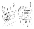
- FIG. 1is a perspective view of a waste collection and disposal system of the present invention illustrating a waste collection unit and a docking station of the system;
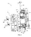
- FIG. 2is perspective view of the waste collection unit with a front cover removed to reveal upper and lower waste containers;
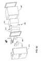
- FIG. 3is an exploded perspective view of the upper and lower waste containers
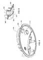
- FIG. 4is a bottom perspective view of the lower cap of the lower waste container without any components attached thereto to illustrate a flow diverter;
- FIG. 5is a cross-sectional view of the flow diverter
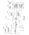
- FIG. 6is a schematic view of the waste collection unit illustrating the upper and lower waste containers and further illustrating the flow of waste material into the upper and lower waste containers and a vacuum circuit for drawing the waste material into the upper and lower waste containers;
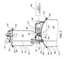
- FIG. 7is a partial cross-sectional view of the upper and lower waste containers illustrating a motor-actuated transfer valve disposed between the waste containers;
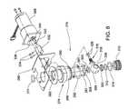
- FIG. 8is an exploded perspective view of the transfer valve and valvemotor
- FIG. 9is a top view of the transfer valve and valve motor
- FIG. 10is a cross-sectional view of the transfer valve and valve motor
- FIG. 11is a graph illustrating a position signal generated by a position sensor associated with the valve motor
- FIG. 12is a block diagram of the transfer valve and associated controls
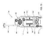
- FIG. 13is a front view of the waste collection unit illustrating upper pocket doors in a closed position and lower pocket doors in a partially open position;
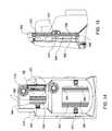
- FIG. 14is a partial cross-sectional view of the waste collection unit illustrating the pocket doors
- FIG. 15is a close-up view of the upper pocket door shown in the cross-sectional view of FIG. 14 ;
- FIG. 16is a rear perspective view of the waste collection unit
- FIG. 17is a fluid and electrical schematic view of the vacuum circuit of the waste collection unit
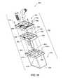
- FIG. 18is an exploded perspective view of a vacuum manifold
- FIG. 19is a top perspective view of a second housing portion of the vacuum manifold.
- FIG. 20is a top perspective view of a first housing portion of the vacuum manifold
- FIG. 21is a bottom perspective view of the second housing portion
- FIG. 22is a bottom perspective view of the second housing portion
- FIG. 23Ais a schematic illustration of a first regulating chamber with a first valve member
- FIG. 23Bis a schematic illustration of a second regulating chamber with a second valve member
- FIG. 24is a front perspective view of the vacuum manifold
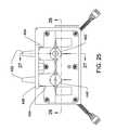
- FIG. 25is a top view of the vacuum manifold
- FIG. 26is a cross-sectional view of the vacuum manifold illustrating the first and second valve members
- FIG. 27is a cross-sectional view of the vacuum manifold illustrating a second main passage
- FIG. 28Ais an illustration of the first valve member in a first position in which fluid communication is open between a vacuum source and the upper waste container;
- FIG. 28Bis an illustration of the first valve member moved to a second position in which fluid communication is closed between the vacuum source and the upper waste container and fluid communication is opened between the upper waste container and atmospheric pressure;
- FIG. 29is a exploded perspective view of a filter unit for the vacuum circuit
- FIG. 30is an exploded perspective view of a filter assembly with float positioned in the upper cap of the upper waste container;
- FIG. 31is a bottom perspective view of the filter assembly disposed in the upper cap
- FIG. 32is a top perspective view of the upper cap
- FIG. 33is a cross-sectional view of the filter assembly
- FIG. 34is an exploded perspective view of a noise attenuator for use in the vacuum circuit
- FIG. 35is a top perspective view of the noise attenuator
- FIG. 36is a cross-sectional view of the noise attenuator
- FIG. 37is an exploded perspective view illustrating an elbow connector used in connecting vacuum and water lines of the waste collection unit
- FIG. 38is a cross sectional diagram of the waste collection unit showing components of the level sensing system
- FIG. 39is an electrical block diagram a level sensing system
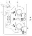
- FIG. 40is a graphical representation of a control panel of the waste collection unit
- FIG. 40Ais a perspective view of a display that is able to rotate and tilt relative on the waste collection unit;
- FIG. 41is a schematic view of the waste collection unit illustrating the flow of fluid into the a smoke evacuation system
- FIG. 42is an exploded perspective view illustrating a filter, housing, and smoke sensor of the smoke evacuation system
- FIG. 43is an electrical schematic showing a circuit for a smoke evacuation system
- FIG. 44is a perspective view of an IV bag support pole assembly
- FIG. 45is an exploded perspective view of the IV bag support pole assembly
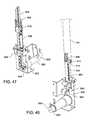
- FIG. 46is a perspective view of a lower portion of the IV bag support pole assembly showing a spring-loaded tape for retracting an IV bag support pole;
- FIG. 47is a perspective view of the lower portion of the IV bag support pole assembly showing a connecting spring providing tension on a belt;
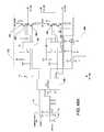
- FIG. 48Ais an electrical schematic showing a motor control circuit, a pole controller, and a power monitoring circuit
- FIG. 48Bis an electrical schematic showing a DC motor and a slowdown circuit
- FIG. 49is a top view of the waste collection unit docked to the docking station.
- FIG. 50is an electrical block diagram of the docking station and the waste collection unit
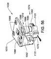
- FIG. 51is an exploded perspective view of a head of the docking station
- FIG. 52is a front perspective view of the head of the docking station
- FIG. 53is a top view of the head of the docking station
- FIG. 54is a rear view of the head of the docking station
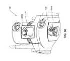
- FIG. 55is a cross-sectional view of the head of the docking station
- FIG. 56is a front perspective view of a floating frame and mating interface of the head
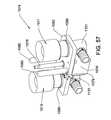
- FIG. 57is a rear perspective view of the mating interface
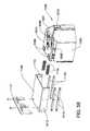
- FIG. 58is an exploded perspective view of a sliding cover plate to cover the head of the docking station when not engaged by the waste collection unit;
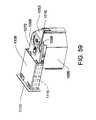
- FIG. 59is a perspective view of the sliding cover plate in a retracted position
- FIG. 60is an exploded perspective view of a carrier and associated rover couplings
- FIG. 61is a bottom perspective view of the carrier
- FIG. 62is an exploded perspective view of a docker coupling
- FIG. 63is an exploded perspective view of a rover coupling
- FIG. 64Ais a cross-sectional view of the head of the docking station and carrier of the waste collection unit showing the docker and rover couplings prior to engagement;
- FIG. 64Bis a cross-sectional view of the head of the docking station and carrier of the waste collection unit showing the docker and rover couplings engaged to permit fluid communication therebetween;
- FIG. 65is a schematic view of a cleaning system of the waste collection unit and the docking station
- FIG. 66is a cut-away view of the waste collection unit showing sprinklers disposed in the upper and lower waste containers;
- FIG. 67is a bottom perspective view of the sprinkler
- FIG. 68is a top perspective view of the sprinkler
- FIG. 69is a side elevational view of the sprinkler
- FIG. 70is a top view of the sprinkler
- FIG. 71is a cross-sectional view of the sprinkler
- FIG. 72is a close-up view of an injection port of the sprinkler from FIG. 71 ;
- FIG. 73is an electrical block schematic diagram of power and data couplers between the waste collection unit and the docking station.
- a waste collection and disposal systemfor collecting and disposing of waste materials is shown generally at 100 .
- the system 100collects and disposes of waste material generated during medical procedures (e.g., surgical procedures) performed in a health care facility such as a hospital.
- the waste materialmay include bodily fluids, body tissues, irrigation liquids, and/or other materials that may be generated during various medical procedures. Often times, medical procedures require large amounts of saline and/or other irrigation liquids for irrigating an anatomical site. As a result, the system 100 is capable of handling large amounts of waste material.
- the system 100comprises a mobile waste collection unit 102 and a fixed docking station 104 .
- the waste collection unit 102collects the waste material generated during the medical procedures.
- the waste collection unit 102may also be referred to as a rover 102 .
- Docking station 104functions as the unit through which waste collected by the waste collection unit 102 is discharged for treatment.
- the docking station 104may also be referred to as a docker 104 .
- the docking station 104also functions to clean the waste collection unit 102 , as explained further below.
- the waste collection unit 102collects the waste material and stores the waste material on-board until such a time as a user is ready to off-load the waste material and dispose of the waste material.
- the waste collection unit 102is capable of storing waste material from a series of different medical procedures during the course of a day or across several days, without requiring off-loading of the waste material.
- the waste collection unit 102is wheeled to the docking station 104 by the user.
- the waste materialis emptied from the waste collection unit 102 to a waste drain D or treatment area, and the waste collection unit 102 is cleaned for further use.
- the system 100includes various features for simplifying use by health care personnel including doctors, nurses, and other users of the system 100 , and for improving patient outcomes from the various medical procedures. Some of the features were designed to increase the on-board waste material storage of these types of systems and to increase the number of uses prior to requiring disposal of the waste material. Other features were designed to reduce the overall time needed by users to collect and dispose of the waste material, to improve volumetric estimations of the waste material collected, and to create cleaner and more inconspicuous docking between the waste collection unit 102 and the docking station 104 . Still other features were designed to simplify smoke removal, to reduce the noise typically experienced when operating such systems, and to improve the odors that often accompany such systems. All of these features are described in detail below.
- the waste collection unit 102utilizes upper 200 and lower 202 waste containers to collect and temporarily store the waste material during use.
- a cart 204supports the waste containers 200 , 202 . More specifically, the waste containers 200 , 202 are stacked one above the other on the cart 204 .
- the cart 204includes a cart base 206 with a lower frame 208 having a generally box shape.
- the lower frame 208supports the lower waste container 202 .
- the lower frame 208is mounted to a top of the cart base 206 .
- An upper frame 210supports the upper waste container 200 .
- the upper frame 210mounts to the lower waste container 202 .
- a plurality of wheels 212are mounted to a bottom of the cart base 206 to provide mobility to the cart 204 .
- a vertical chassis 214is fixed to the cart base 206 and extends upwardly from the cart base 206 .
- a handle 216is mounted to the vertical chassis 214 to facilitate movement of the waste collection unit 102 between use areas, and between the use areas and the docking station 104 .
- userscan move the cart 204 around the health care facility to collect waste material generated during medical procedures performed in different locations throughout the health care facility.
- a front cover Fremoved to show the waste containers 200 , 202 in FIG. 2 , mounts to the cart base 206 and the vertical chassis 214 to conceal internal components of the waste collection unit 102 .
- the front cover Fis preferably formed of a plastic material. Transparent windows 362 , 364 (see FIG. 2 ) are present in openings in the front cover F to allow viewing of the canisters 218 , 224 and their contents.
- the upper waste container 200comprises an upper canister 218 that is slightly frusto-conical in shape, but appears generally cylindrical.
- the upper canister 218defines an upper waste chamber 220 for holding waste material.
- An upper cap 222covers the upper canister 218 to close the upper waste chamber 220 .
- the lower waste container 202comprises a lower canister 224 that is also slightly frusto-conical in shape.
- the lower canister 224defines a lower waste chamber 226 for holding waste material.
- a lower cap 228covers the lower canister 224 to close the lower waste chamber 226 .
- the canisters 218 , 224may assume any shape that is suitable for containing the waste material.
- the caps 222 , 228are preferably formed of a polymeric material such as plastic and have external and internal surfaces. Structural support members 225 are formed on the external surfaces of the caps 222 , 228 to provide further rigidity to the caps 222 , 228 and prevent collapse. Conversely, the opposing internal surfaces of the caps 222 , 228 are free of any structural support members 225 to provide a smooth, uninterrupted internal surface for easier cleaning.
- the upper canister 218is preferably smaller in diameter and storage volume than the lower canister 224 to provide a relatively better estimation of the volume of waste material collected in the upper canister 218 as compared to the lower canister 224 .
- the upper canister 218has a maximum storage volume of from about 0.5 liters to about 10 liters, more preferably from about 2 liters to about 7 liters, and most preferably from about 2 liters to about 6 liters. In the embodiment shown, the maximum storage volume of the upper canister 218 is 4 liters.
- the lower canister 224has a maximum storage volume of from about 10 liters to about 50 liters, more preferably from about 15 liters to about 30 liters, and most preferably from about 18 liters to about 25 liters. In the embodiment shown, the maximum storage volume of the lower canister 224 is about 20 liters.
- the maximum storage volumeis the amount of waste material that can be stored in each of the canisters 218 , 224 before an electronic or mechanical shutoff prevents further filling of the canisters 218 , 224 .
- the canisters 218 , 224may be placed side-by-side on the cart 204 and the canisters 218 , 224 may both be large or both be small, or additional canisters (not shown) could be employed.
- the upper canister 218is disposed above the lower canister 224 on the cart 204 with respect to gravity such that the waste material collected in the upper canister 218 can be emptied into the lower canister 224 via gravity.
- the waste material collected in the upper canister 218can be emptied several times into the lower canister 224 without filling the lower canister 224 beyond its maximum storage volume.
- the maximum storage volume of the lower canister 224is greater than twice the maximum storage volume of the upper canister 218 such that the waste material collected in the upper canister 218 can be emptied at least twice into the lower canister 224 before the lower canister 224 is filled to its maximum storage volume.
- each of the canisters 218 , 224may be formed of glass or suitable plastic materials.
- Each of the canisters 218 , 224includes a bottom 230 , 232 , respectively.
- An outer wall 234 , 236respectively, extends upwardly from the bottom 230 , 232 to secure the waste material in the canisters 218 , 224 during use.
- Each of the outer walls 234 , 236extends upwardly from the bottom 230 , 232 to an open end.
- An annular rim 238 , 240respectively, extends circumferentially around each of the outer walls 234 , 236 at the open ends.
- the rims 238 , 240define grooves 242 , 244 .
- An elastomeric seal 246 , 248is disposed in each of the grooves 242 , 244 to seal the caps 222 , 228 to the canisters 218 , 224 . More specifically, each of the caps 222 , 228 is generally dome-shaped with a peripheral lip 250 , 252 , respectively, that engages the rim 238 , 240 of the canisters 218 , 224 with the elastomeric seal 246 , 248 trapped therebetween.
- a V-clamp 254 , 256respectively, secures the caps 222 , 228 to the canisters 218 , 224 by clamping the peripheral lips 250 , 252 to the rims 238 , 240 .
- manifold receivers 258are mounted to each of the caps 222 , 228 .
- the manifold receivers 258are adapted to receive disposable manifolds 260 (see FIG. 2 ), which direct waste material from one or more sites in proximity to a patient, through suction lines 262 , into the canisters 218 , 224 .
- the manifold receivers 258act as one type of connecting member of the waste containers 200 , 202 for connecting the suction lines 262 to the waste containers 200 , 202 .
- Two suction lines 262are shown attached to each of the disposable manifolds 260 in FIG. 2 .
- suction line 262only one suction line 262 could be used, or additional suction lines 262 could be employed to capture waste material from the sites.
- the distal end of each suction line 262the end closest to a patient is connected to a suction applicator. It is appreciated that the suction applicator is the actual surgical handpiece applied to the surgical site in order to draw waste away from the site. Some suction applicators are built into other tools, such as shavers that perform another procedure in addition to serving as the suction handpiece. The exact structure of the suction applicator is not relevant to the construction of this invention.
- the disposable manifolds 260preferably include a filter (not shown) to filter the waste material received from the suction lines 262 prior to the waste material entering the canisters 218 , 224 .
- the disposable manifolds 260 and associated filters, and their attachment to the manifold receivers 258 mounted to the caps 222 , 228are described in detail in co-pending U.S. patent application Ser. No. 11/554,616 to Murray et al., entitled, REMOVABLE INLET MANIFOLD FOR A MEDICAL/SURGICAL WASTE COLLECTION SYSTEM, THE MANIFOLD INCLUDING A DRIVER FOR ACTUATING A VALVE INTEGRAL WITH THE WASTE COLLECTION SYSTEM, filed Oct.
- each of the manifold receivers 258includes a boss 264 with associated o-ring 266 , as shown in FIG. 4 . This is also shown in application Ser. No. 11/554,616, hereby incorporated by reference.
- the boss 264fits into a waste port 268 defined in the lower cap 228 .
- a flow diverter 270is integrally formed at a bottom of the waste port 268 to direct the flow of waste material away from a center axis of the lower canister 224 toward the outer wall 236 of the lower canister 224 .
- the flow diversion resulting from the flow diverter 270reduces the amount of disturbance of the liquid surface inside the lower waste container 202 . This feature assists in improving the accuracy of volumetric measurement, as described further below, by reducing turbulence in the liquid surface. It should be appreciated that although only the lower cap 228 is shown, the upper cap 228 includes the same feature for accommodating a manifold receiver 258 .
- FIG. 6a schematic representation of waste material being collected by the waste collection unit 102 is shown.
- a vacuumis pulled in each of the waste containers 200 , 202 with a vacuum circuit 400 , described further below, to draw the waste material into the waste containers 200 , 202 from the sites in proximity to the patient.
- waste materialis drawn through the suction lines 262 , disposable manifolds 260 , and finally through the waste ports 268 defined in the caps 222 , 228 to enter the canisters 218 , 224 .
- Userscan select to simultaneously collect waste material in both waste containers 200 , 202 or one at a time.
- a transfer valve 276is disposed between the upper canister 218 and the lower canister 224 to facilitate emptying of the waste material from the upper canister 218 to the lower canister 224 via gravity.
- the transfer valve 276is selectively closed to retain cleaning fluid in the upper canister 218 during cleaning (described further below).
- the transfer valve 276is also selectively closed to seal the vacuum path between the waste containers 200 , 202 to allow independent vacuum regulation (also described further below).
- the transfer valve 276moves between open and closed positions. In the open position, the waste material that was present in the upper canister 218 drains, under the force of gravity, to the lower canister 224 . In the closed position, the waste material is retained in the upper canister 218 .
- the transfer valve 276is preferably in the form of a ball valve.
- the upper canister 218can be emptied and readied for continued use between medical procedures without requiring off-board disposal of the waste material. This reduces the number or trips that a user has to make between the use areas (e.g., operating rooms), in which the waste material is being collected, and the docking station 104 , which is typically located outside of the use areas, usually near the waste drain D.
- the transfer valve 276includes a valve body 278 mounted to a bracket 280 .
- the valve body 278is formed of polyvinylchloride or polypropylene. Fasteners 281 secure the valve body 278 to the bracket 280 .
- the bracket 280is fixed to the upper frame 210 that supports the upper waste container 200 .
- the valve body 278defines an upper cavity 282 for receiving a neck 286 of the upper canister 218 (see FIG. 7 ).
- the neck 286is integrally formed with the bottom 230 and the outer wall 234 of the upper canister 218 and extends downwardly from the bottom 230 . As shown in FIG.
- an o-ring 274seals the neck 286 in the upper cavity 282 .
- the valve body 278also includes a lower portion 288 .
- the lower portion 288has an outer surface defining a groove 290 .
- the lower portion 288is adapted to seat in a valve port 294 integrally formed in the lower cap 228 .
- An o-ring 292seals the lower portion 288 in the valve port 294 .
- a ball 296is seated in a main chamber 298 of the valve body 278 .
- the ball 296is formed of polyvinylchloride or polypropylene.
- the ball 296is supported in the main chamber between first 300 and second 302 valve seats.
- the valve seats 300 , 302are annular in shape and include a slightly concave face to receive the ball 296 in a tight sealing manner.
- the first valve seat 300abuts an internally facing annular shoulder 304 forming an upper boundary of the main chamber 298 .
- the annular shoulder 306defines a downwardly facing groove facing into the main chamber 298 .
- An o-ring 308is seated in the downwardly facing groove to seal the first valve seat 300 to the valve body 278 .
- a nut 310screws into the lower portion 288 to secure the ball 296 in the valve body 278 .
- the nut 310is formed of polyvinylchloride or polypropylene.
- the second valve seat 302is captured between the nut 310 and the ball 296 .
- the nut 310defines an upwardly facing groove and a radially outwardly facing groove.
- An o-ring 312is seated in the upwardly facing groove to seal the nut 310 against the second valve seat 302 .
- Another o-ring 314is seated in the radially outwardly facing groove to seal the nut 310 against an interior of the valve body 278 .
- a valve stem 316is coupled to the ball 296 to rotate the ball 296 .
- the ball 296defines a stem pocket and the valve stem 316 includes a stem head 318 corresponding in shape to the stem pocket.
- the stem head 318is elongated in one dimension. When the stem head 318 mates with the stem pocket, the stem head 318 is rotatably fixed to the ball 296 .
- the ball 296 and stem head 318form a complete ball shape when engaged together.
- the stem head 318includes a first annular shoulder 320 .
- the valve stem 316extends from the annular shoulder 320 to a far end opposite the stem head 318 .
- the valve body 278defines a generally cylindrical sleeve 322 for receiving the valve stem 316 .
- the sleeve 322includes a second annular shoulder 324 that abuts the first annular shoulder 320 to prevent the valve stem 316 from popping out of the main chamber 298 through the sleeve 322 .
- the valve stem 316extends from the ball 296 in the main chamber 298 through the sleeve 322 to the far end.
- the valve stem 316is generally cylindrically and is rotatably supported in the sleeve 322 .
- O-rings 326seal the valve stem 316 in the sleeve 322 .
- a transfer valve motor 328is operatively coupled to the transfer valve 276 to move the transfer valve 276 between the open position in which fluid communication is opened between the canisters 218 , 224 and the closed position in which fluid communication between the canisters 218 , 224 is closed.
- the valve motor 328is mounted to the bracket 280 .
- the valve motor 328includes a motor shaft 330 rotationally coupled to the far end of the valve stem 316 via a coupler 332 . Fasteners 334 secure the coupler 332 to the far end of the valve stem 316 and the motor shaft 330 .
- the motor shaft 330rotates the ball 296 to move the transfer valve 276 between the open and closed positions.
- the ball 296includes a through opening 336 that aligns with passages in the neck 286 of the upper canister 218 and the valve port 294 of the lower cap 228 in the open position.
- the through opening 336is normal to the passages of the neck 286 and the valve port 294 in the closed position such that the ball 296 seals the neck 286 from the valve port 294 .
- the closed positionis shown in FIG. 10 .
- a position sensor 338responds to movement of the transfer valve 276 between the open and closed positions to sense a current position of the transfer valve 276 .
- a single position sensor 338is utilized to generate a position signal that follows a generally non-linear voltage path between the open and closed positions, as shown in FIG. 11 .
- the position sensor 338is preferably a hall-effect sensor that detects rotation of a metallic sensing plate 340 , formed of carbon steel in one embodiment.
- the sensing plate 340has a cammed shape (see also FIG. 8 ). This cammed shape generates the position signal voltage path shown in FIG. 11 between the open and closed positions. It should be appreciated that other position sensors such as contact switches could alternatively be placed to sense when the transfer valve 276 is at the open and/or closed positions.
- a main controller 342operates the waste collection unit 102 .
- the main controller 342includes a plurality of sub-controllers (with their own microprocessors, memory, etc.) that operate specific features of the waste collection unit 102 .
- the sub-controllersmay communicate with the main controller 342 along a communications bus or by other conventional methods.
- One of the sub-controllersis a valve controller 344 .
- the valve controller 344including appropriate microprocessors, controls valve motor 328 to move the transfer valve 276 between the open and closed positions as needed.
- An on-board control panel 310is in communication with the main controller 342 to allow user selected operation of the valve motor 328 .
- the usermay select to transfer the waste material from the upper canister 218 to the lower canister 224 by actuating a pushbutton 348 (see FIG. 40 ) or other suitable user-selectable control of the control panel 310 .
- the usercan request dumping at any time during use such as when the upper canister 218 is full, or simply when the user desires an empty upper canister 218 .
- the main controller 342is programmed to first instruct the valve controller 344 to instruct the valve motor 328 to move the transfer valve 276 to the open position to empty the waste material into the lower canister 224 .
- the valve motor 328is then automatically instructed to move back to the closed position once upper canister 218 emptied, as determined by a fluid measuring system described further below, or by monitoring time and closing the transfer valve 276 after the time typically associated with transferring waste from a full upper canister 218 has elapsed.
- the position signal generated by the position sensor 338is transmitted to the valve controller 344 to control this operation. With the opposing steep slopes of the voltage path generated by the position signal at the open and closed positions, the valve controller 344 can quickly determine which position the transfer valve 276 is in.
- the main controller 342may automatically instruct the valve controller 344 to move the transfer valve 276 without requiring user instruction. This is particularly true during a cleaning cycle, described further below, in which the main controller 342 , via the valve controller 344 , selectively opens and closes the transfer valve 276 to drain, clean, and rinse the waste containers 200 , 202 .
- upper 350 and lower 352 pocket doorsselectively conceal and reveal the upper 218 and lower 224 canisters during use. This is particularly advantageous when wheeling the waste collection unit 102 down hallways in the health care facility in which other patients or family members may be present.
- the pocket doors 350 , 352allow the user to conceal the canisters 218 , 224 to prevent others from seeing the potentially offensive waste material contained therein.
- the pocket doors 350 , 352slide in upper 354 and lower 356 tracks.
- the tracks 354 , 356are fixed to an interior of the front cover F by an adhesive or may be integrally formed in the front cover F. Thus, the tracks 354 , 356 are arcuate in shape along their length.
- the canisters 218 , 224can be viewed through the transparent windows 362 , 364 (see FIG. 2 ) when the pocket doors 350 , 352 are open.
- the upper pocket door 350which is of the same construction as the lower pocket door 352 , includes inner 366 and outer 368 plastic panels.
- the panels 366 , 368are crimped together from top to bottom at predetermined spaces to form a plurality of hinges 369 (see FIG. 14 ).
- These hinges 369allow the pocket doors 350 , 352 to bend along the arcuate shaped tracks 354 , 356 when sliding between open and closed positions.
- a single arcuate panelmay be employed to slide in the tracks 354 , 356 .
- Ball bearings or other suitable bearing mechanismscould be employed to facilitate sliding of the pocket doors 350 , 352 in the tracks 354 , 356 .
- a plastic or foam intermediate layer 370may be sandwiched between the panels 366 , 368 in the sections between the hinges 369 , as shown in FIG. 15 .
- the panels 366 , 368may be glued to the intermediate layer 370 with an adhesive.
- the intermediate layer 370helps to provide some thickness to the pocket doors 350 , 352 while also reducing the weight of the pocket doors 350 , 352 and maintaining flexibility in the pocket doors 350 , 352 .
- a knob 372is mounted through the upper pocket door 314 via a fastener 374 . The user grasps the knob 372 to slide the upper pocket door 314 along its upper 354 and lower 356 tracks between the open and closed positions.
- similar doors or covers for concealing the canisters 218 , 224may be hinged or snap-fit in place, or mounted in any other configuration that achieves the purpose of concealing the canisters 218 , 224 from view or exposing the canisters 218 , 224 when desired by the user.
- FIG. 16a rear perspective view of the waste collection unit 102 is shown.
- a storage bracket 376 defining a storage compartment 378is shown for storing clipboards, patient charts, disposable manifolds 260 , and the like.
- the storage bracket 376is mounted to a rear cover R of the waste collection unit 102 .
- the rear cover Rcould include multiple, independent panels, or be a single enclosure.
- the rear cover Rmay include two U-shaped sheet metal panels surrounding the back of the waste collection unit 102 , one that includes a pair of bumpers, and one that includes the storage bracket 376 .
- the rear cover Rmay also include a third plastic cover with a beveled shape that carriers the control panel 310 .
- a control panel display 380is shown on the control panel 310 to provide readouts for operation of the waste collection unit 102 , as described further below.
- the control panel display 380may be a liquid crystal-type (LCD), but other types of displays are known to those skilled in the art.
- the control panel 310 and control panel display 380are electronically coupled to the main controller 342 of the waste collection unit 102 .
- the vacuum circuit 400forms part of a vacuum control assembly (or vacuum regulating assembly) that provides independently controllable vacuum levels in each of the waste containers 200 , 202 . As a result, the user can establish different vacuum levels for the waste containers 200 , 202 depending on the particular needs of the medical procedure being performed.
- the vacuum circuit 400comprises a vacuum source 402 for providing the vacuum available to the waste containers 200 , 202 .
- the vacuum source 402is a rotary vane type vacuum pump 402 mounted to the cart base 206 of the cart 204 to provide an on-board vacuum pump.
- One such vacuum pump 402is a Gast 1023 Series 12 CFM rotary vane vacuum pump, Part No.
- the vacuum circuit 400splits into parallel lines that extend from the vacuum pump 402 to the waste containers 200 , 202 .
- the vacuum source 402may be a hospital vacuum system, located remotely from the cart 204 .
- the waste collection unit 102is outfitted with the on-board vacuum pump 402 , while also providing a plurality of back-up ports 404 capable of connection to the hospital vacuum system.
- the back-up ports 404can be used should the on-board vacuum pump 402 fail or should the user desire to use the hospital vacuum system in lieu of the vacuum pump 402 .
- a check valve 406is associated with each of the back-up ports 404 to prevent air from entering the vacuum circuit 400 through the back-up ports 404 when not in use. For simplicity, only the vacuum pump 402 shall be described below.
- upper 408 and lower 410 vacuum regulatorsare included in the vacuum circuit 400 .
- the vacuum regulators 408 , 410are supported on the cart 204 for adjusting the vacuum levels in the waste containers 200 , 202 .
- the upper vacuum regulator 408comprises a first valve member 412 .
- a first actuator 414is operatively coupled to the first valve member 412 to move the first valve member 412 and selectively open fluid communication or air transfer between the upper waste container 200 and atmospheric pressure A or between the upper waste container 200 and the vacuum pump 402 .
- a first position sensor 416is responsive to movement of the first valve member 412 .
- the lower vacuum regulator 410comprises a second valve member 418 .
- a second actuator 420is operatively coupled to the second valve member 418 to move the second valve member 418 and selectively open fluid communication or air transfer between the lower waste container 202 and atmospheric pressure or between the lower waste container 202 and the vacuum pump 402 .
- a second position sensor 422is responsive to movement of the second valve member 418 .
- the vacuum regulators 408 , 410are preferably configured to prevent fluid communication or air transfer between the vacuum pump 402 and atmospheric pressure A. This reduces the amount of total vacuum pressure lost during use such that a single vacuum pump 402 can provide suitable vacuum levels in both the upper 200 and lower 202 waste containers during use, even if both are being used to collect waste material simultaneously.
- the main controller 342controls operation of the vacuum regulators 408 , 410 through upper 411 and lower 413 vacuum controllers (e.g., separate microcontrollers) to maintain desired vacuum levels in each of the waste containers 200 , 202 .
- Knobs or dials, 311 , 313in communication with the main controller 342 , are disposed on the control panel 310 to allow the user to establish the desired vacuum levels in the waste containers 200 , 202 .
- Each of the dials 311 , 313is associated with one of the waste containers 200 , 202 , respectively, to control the vacuum level in the corresponding waste container 200 , 202 .
- the usermay choose to shut off the vacuum inside one of the waste containers 200 , 202 , while maintaining a desired vacuum level in the other waste container 200 , 202 .
- the usermay choose to set two, different vacuum levels for the waste containers 200 , 202 .
- the main controller 342instructs the upper 411 and lower 413 vacuum controllers to move the vacuum regulators 408 , 410 accordingly until the desired vacuum levels are reached.
- the control panel display 380visually displays the current vacuum levels in each of the waste containers 200 , 202 .
- Separate sets of pressure sensors 424 , 426are responsive to pressure changes in each of the waste containers 200 , 202 .
- the pressure sensors 424 , 426generate corresponding pressure signals sent to the vacuum controllers 411 , 413 .
- the first set of pressure sensors 424generate pressure signals corresponding to the vacuum level in the upper waste container 200 .
- the second set of pressure sensors 426generate pressure signals corresponding to the vacuum level in the lower waste container 202 .
- One of each of these sets of pressure signals 424 , 426is sent to each of the vacuum controllers 411 , 413 .
- each of the vacuum controllers 411 , 413receives one pressure signal corresponding to the vacuum level in the upper waste container 200 and one pressure signal corresponding to the vacuum level in the lower waste container 202 .
- This redundancyallows the main controller 342 to compare pressure readings and determine whether any of the pressure sensors 424 , 426 are malfunctioning or whether either of the vacuum controllers 411 , 413 are malfunctioning. Accordingly, the vacuum regulators 408 , 410 are controlled based on the feedback provided by the pressure signals generated by the pressure sensors 424 , 426 .
- Additional check valves 428are disposed between the upper vacuum regulator 408 and the vacuum pump 402 and between the lower vacuum regulator 410 and the vacuum pump 402 . These check valves 428 prevent air from traveling from the vacuum pump 402 when the back-up ports 404 are being used. Otherwise, the hospital vacuum system would not be able to draw a suitable vacuum in the containers 200 , 202 during use.
- a vacuum manifold 430integrates both of the vacuum regulators 408 , 410 into a single unit.
- the vacuum manifold 430comprises a first housing portion 432 connected to a second housing portion 434 .
- the housing portions 432are preferably formed of plastic materials, but may be formed of other materials including metallic materials.
- a plurality of fasteners 436secures the first housing portion 432 to the second housing portion 434 .
- the first 432 and second 434 housing portionsare best shown in FIGS. 19 through 22 .
- the first housing portion 432includes a base section 438 .
- First 440 and second 442 tower sectionsare disposed on the base section 438 and extend away from the base section 438 .
- a first main passage 444extends longitudinally and completely through the first tower section 440 .
- a second main passage 446extends longitudinally and completely through the second tower section 442 .
- two of the back-up ports 404extend from each of the tower sections 440 , 442 in selective fluid communication with the corresponding main passage 444 , 446 .
- the check valves 406 associated with the back-up ports 404are sealed in each of the back-up ports 404 to prevent air from rushing into the corresponding main passage 444 , 446 when the back-up ports 404 are not in use.
- the check valves 406may be used in conjunction with port caps (not shown), but do not require port caps for their specific function.
- the check valves 406may be check valve cartridges commercially available from Neoperl, Inc. of Waterbury, Conn. An example of such a check valve is shown in U.S. Pat. No. 6,837,267 to Weis et al., hereby incorporated by reference.
- a nozzle plate 448is mounted to both of the tower sections 440 , 442 .
- a plurality of fasteners 450secures the nozzle plate 448 to the tower sections 440 , 442 .
- the nozzle plate 448includes a plurality of tapered nozzles 452 integrally formed in the nozzle plate 448 and extending away from the back-up ports 404 .
- the tapered nozzles 452act as extensions of the back-up ports 404 .
- the hospital vacuum systemis connected to the vacuum manifold 430 by placing hospital vacuum tubes (not shown) from the hospital vacuum system onto the tapered nozzles 452 . In the preferred embodiment shown, two pairs of the tapered nozzles 452 are provided.
- Each pairis in fluid communication with the associated main passage 444 , 446 in the tower section 440 , 442 to which the back-up ports 404 are attached.
- two separate vacuum tubes from the hospital vacuum systemcan be used to provide vacuum to each of the waste containers 200 , 202 .
- a pair of o-rings 454seals the nozzle plate 448 to the back-up ports 404 .
- the second housing portion 434defines first 456 and second 458 cavities.
- a first central hub 460is generally disposed centrally in the first cavity 456 .
- a first plurality of support ribs 462integrally connects the first central hub 460 with a first inner ring 464 .
- a first plurality of webs 466extend radially outwardly from the first inner ring 464 to a first peripheral wall 468 to define a first plurality of pockets 470 .
- a second central hub 472is generally disposed centrally in the second cavity 458 .
- a second plurality of ribs 474integrally connects the second central hub 472 with a second inner ring 476 .
- a second plurality of webs 478extend radially outwardly from the second inner ring 476 to a second peripheral wall 480 to define a second plurality of pockets 482 .
- the ribs 462 , 474 and the webs 466 , 478are designed to provide structural rigidity to the first 456 and second 458 cavities. They are designed to withstand vacuum pressures exceeding 26 inches of Hg.
- O-rings 488are positioned in grooves 490 , 492 surrounding the peripheral walls 468 , 480 . These o-rings 488 seal the first housing portion 432 to the second housing portion 434 .
- the first 456 and second 458 cavitiesform first 484 and second 486 regulating chambers when the first housing portion 432 is connected to the second housing portion 434 .
- the regulating chambers 484 , 486are schematically represented in FIGS. 23A and 23B .
- the first regulating chamber 484includes a first inlet 494 in fluid communication with the upper waste container 200 and a first passage 506 open to atmospheric pressure A.
- the first regulating chamber 484also includes a first outlet 504 in fluid communication with the vacuum pump 402 .
- the first inlet 494is preferably in the form of a barbed nozzle 494 for receiving one end of a vacuum line 496 .
- the vacuum line 496is sealed about the barbed nozzle 494 by a hose clamp 498 .
- the other end of the vacuum lineis connected to an elbow joint 500 by another hose clamp 502 .
- the elbow joint 500is adapted to connect to the upper cap 222 of the upper waste container 200 , as described further below.
- the first outlet 504is further defined as the entrance to the first main passage 444 (see FIG. 21 ) defined through the first tower section 440 .
- the first passage 506is formed in a first block 507 (see FIG. 21 ) attached the first tower section 440 .
- the second regulating chamber 486includes a second inlet 508 in fluid communication with the lower waste container 202 and a second passage 514 open to atmospheric pressure A.
- the second regulating chamber 486also includes a second outlet 512 in fluid communication with the vacuum pump 402 .
- the second inlet 508is preferably in the form of a barbed nozzle 508 for receiving one end of a second vacuum line 510 .
- the second vacuum line 510is sealed about the barbed nozzle 508 by a hose clamp 498 .
- the other end of the second vacuum line 510is connected to an elbow joint 500 by another hose clamp 498 .
- the elbow joint 500is adapted to connect to the lower cap 228 of the lower waste container 202 , as described further below.
- the second outlet 512is further defined as the entrance to the second main passage 446 (see FIG. 21 ) through the second tower section 442 .
- the second passage 514is formed in a second block 515 (see FIG. 21 ) attached to the second tower section 442 .
- the first valve member 412is disposed in the first regulating chamber 484 .
- the first valve member 412has a disk shape.
- the first actuator 414is a first position sensing motor 414 adapted to rotate the first valve member 412 between a plurality of rotational positions.
- the first valve member 412defines a first source opening 516 for providing variable fluid communication between the first inlet 494 and the first outlet 504 and a first vent opening 518 for providing variable fluid communication between the first inlet 494 and the first passage 506 .
- the first position sensing motor 414rotates the first valve member 412 to adjust the vacuum level in the upper waste container 200 by regulating the amount of fluid flowing through the first valve member 412 .
- the first valve member 412is spaced from a top of the webs 466 such that fluid can pass beneath the first valve member 412 from the first inlet 494 to the first outlet 504 or to the first passage 506 when the first source opening 516 or the first vent opening 518 are properly aligned.
- the first position sensing motor 414is mounted to a bracket 520 and includes a first drive shaft 522 that protrudes through the bracket 520 and the first central hub 460 to engage the first valve member 412 at its center.
- a bushing 524is disposed in a counterbore in the first central hub 460 and surrounds the first drive shaft 522 .
- An o-ringseals the first drive shaft 522 in the first central hub 460 .
- the bracket 520attaches the vacuum manifold 430 to the vertical chassis 214 of the cart 204 .
- the second valve member 418is disposed in the second regulating chamber 486 .
- the second valve member 418has a disk shape and is rotatably coupled to the second actuator 420 .
- the second actuator 420is a second position sensing motor 420 adapted to rotate the second valve member 418 between a plurality of rotational positions.
- the second valve member 418defines a second source opening 528 for providing variable fluid communication between the second inlet 508 and the second outlet 512 and a second vent opening 530 for providing variable fluid communication between the second inlet 508 and the second passage 514 .
- the second valve member 418is spaced from a top of the webs 478 such that fluid can pass beneath the second valve member 418 from the second inlet 508 to the second outlet 512 or to the second passage 514 when the second source opening 528 or the second vent opening 530 are properly aligned.
- the second position sensing motor 420is mounted to the bracket 520 and includes a second drive shaft 532 that protrudes through the bracket 520 and the second central hub 472 to engage the second valve member 418 at its center.
- a bushing 534is disposed in a counterbore in the second central hub 472 and surrounds the second drive shaft 532 .
- An o-ringseals the second drive shaft 532 in the second central hub 472 .
- first 538 and second 540 groovesare defined about the first outlet 504 and the second outlet 512 .
- third 542 and fourth 544 groovesare defined about the first passage 506 and the second passage 514 .
- first 546 and second 548 face sealsare seated in the first 538 and second 540 grooves and third 550 and fourth 552 face seals are seated in the third 542 and fourth 544 grooves.
- face seals 546 , 548 , 550 , 552seal between the first 412 and second 418 regulator disks and the first housing portion 432 to prevent the undesired movement of fluid.
- the first valve member 412is shown in a position in which the first source opening 516 partially overlaps with the first outlet 504 to allow fluid communication between the first inlet 494 and the first outlet 504 .
- Thisopens fluid communication between the upper waste container 200 and the vacuum pump 402 .
- the amount of overlapcan be varied to increase or decrease the vacuum level in the upper waste container 200 .
- the upper waste container 200is exposed to the full vacuum available from the vacuum pump 402 .
- By completely misaligning the first source opening 516 relative to the first outlet 504fluid communication is closed between the vacuum pump 402 and the upper waste container 200 .
- the first vent opening 518is not aligned whatsoever with the first passage 506 such that there is no fluid communication between the upper waste container 200 and atmospheric pressure A.
- the first valve member 412is shown moved to a position in which the first source opening 516 is not aligned whatsoever with the first outlet 504 .
- fluid communicationis closed between the vacuum pump 402 and the upper waste container 200 .
- the first vent opening 518overlaps with the first passage 506 such that the upper waste container 200 is exposed to atmospheric pressure A to drive the vacuum level in the upper waste container 200 closer to atmospheric pressure A from its current pressure.
- the principles discussed hereapply equally to the second valve member 418 , but only the first valve member 412 is discussed for convenience.
- the regulator disks 412 , 418are shown formed of plastic materials, but they may also be formed of metallic materials such as stainless steel and the like.
- the main controller 342controls the vacuum controllers 411 , 413 , which control movement of the first 412 and second 418 regulator disks as previously discussed.
- Each of the position sensing motors 414 , 420includes an integrated position sensor 416 , 422 that senses movement of the drive shafts 522 , 532 , which corresponds to movement of the regulator disks 412 , 418 .
- the position signals generated by the position sensors 416 , 422vary.
- the position signalsare communicated to the vacuum controllers 411 , 413 to determine a current position of the regulator disks 412 , 418 .
- This feedbackis utilized by the vacuum controllers 411 , 413 , along with the pressure signals associated with the waste containers 200 , 202 , to determine how to adjust the regulator disks 412 , 418 to achieve the desired vacuum levels in the waste containers 200 , 202 .
- first 554 and second 556 pairs of sensor tubesare attached to nipples 558 disposed on the second housing portion 434 of the vacuum manifold 430 .
- One of the first pair 554 and one of the second pair 556 of the sensor tubesextend from the second housing portion 434 to the pressure sensors 424 , 426 .
- These sensor tubes 554 , 556essentially carry the existing vacuum levels in the waste containers 200 , 202 back to the pressure sensors 424 , 426 .
- a filter unit 1300filters the fluid drawn into the vacuum circuit 400 by the vacuum pump 402 .
- the filter unit 1300includes a filter housing 1302 for receiving a filter cartridge 1304 .
- the filter housing 1302may be formed of plastic or metallic materials.
- the filter housing 1302includes a first hollow base section 1306 .
- a mounting bracket 1308is integrally formed with the first hollow base section 1306 to mount the first hollow base section 1306 to the vertical chassis 214 of the cart 204 .
- An outlet 1310is defined in the first hollow base section 1306 .
- a tee connector 1313is disposed in the outlet and secured there by a retaining clip C.
- a relief valve 1312connects to one end of the tee connector 1313 and a barbed nozzle 1311 connects to the other end of the tee connector 1313 .
- the barbed nozzle 1311connects to a vacuum line 1314 extending to the vacuum pump 402 .
- a first hollow body section 1316extends forwardly from the first hollow base section 1306 .
- a second mounting bracket 1318is integrally formed with the first hollow body section 1316 to mount the first hollow body section 1316 to the vertical chassis 214 .
- a pair of inlets 1320extends from the first hollow body section 1316 .
- One of the inlets 1320connects to a vacuum line 1322 that extends from the connector 500 mounted to the first tower section 440 (see FIG. 24 ).
- the other inlet 1320connects to a vacuum line 1324 that extends from the connector 500 mounted to the second tower section 442 (see FIG. 24 ).
- Two hollow neck sections 1326extend forwardly from the first hollow body section 1316 .
- the two check valves 428are inserted inside the hollow neck sections 1326 just downstream of the inlets 1320 .
- Retainers 1328hold the check valves 428 inside the hollow neck sections 1326 .
- the check valves 428may be check valve cartridges commercially available from Neoperl, Inc. of Waterbury, Conn. An example of such a check valve is shown in U.S. Pat. No. 6,837,267 to Weis et al., hereby incorporated by reference.
- the first hollow base section 1306 and first hollow body section 1316are integrally formed to define a chamber for receiving the filter cartridge 1304 .
- the filter cartridge 1304includes a cartridge housing 1330 with a second hollow base section 1332 having a hollow boss 1334 .
- a second hollow body section 1336extends forwardly from the second hollow body section 1316 .
- the second hollow body section 1336may be integrally formed with the second hollow base section 1306 or may be a separate component joined to the second hollow base section 1306 .
- a HEPA filter element 1338is shaped to fit snugly inside the second hollow body section 1336 .
- An activated carbon filter element 1340is shaped to fit snugly inside the second hollow base section 1332 .
- the activated carbon filter element 1340has a porosity of 10 to 30 pores per inch, most preferably 20 pores per inch, and is impregnated with activated carbon.
- the activated carbon in the activated carbon filter element 1340helps to remove foul odors associated with the fluid drawn into the vacuum circuit 400 .
- the activated carbon filter element 1340is preferably provided in a spiral configuration. This spiral configuration provides a compact package that allows longer fluid contact time with the activated carbon since the fluid follows the spiral. The longer contact time, along with the depth of the carbon, allows the activated carbon to remove more foul odors and last longer.
- a plastic cover 1341mounts to the first 1306 and second 1332 hollow base sections to secure the activated carbon filter element 1340 in the second hollow base section 1332 and to secure the filter cartridge 1304 in the filter housing 1302 .
- the first 1306 and second 1332 hollow base sectionsinclude first 1343 and second 1345 pairs of ears for receiving fasteners (not shown) to mount the cover 1341 to the hollow base sections 1306 , 1332 .
- the cover 1341may only mount to the second hollow base section 1332 to be an integrated and disposable part of the disposable filter cartridge 1304 .
- a filter door w/foam backing(not shown) is mounted to the rear cover R and presses against the cover 1341 to hold the filter cartridge 1304 inside the filter housing 1302 .
- An o-ring 1342surrounds the second hollow body section 1336 to seal the second hollow body section 1336 inside the hollow body section 1316 of the filter housing 1302 .
- the o-ring 1342prevents fluid that enters the filter housing 1302 through the inlets 1320 from passing around the second hollow body section 1336 and instead forces the fluid to enter the HEPA filter element 1338 .
- the boss 1334has an o-ring 1344 that seals the hollow boss 1334 inside the outlet 1310 of the filter housing 1302 to prevent fluid from passing around the hollow boss 1334 on its way out through the outlet 1310 . This forces the fluid to pass into the inlets 1320 , through the HEPA filter element 1338 and the activated carbon filter element 1340 before exiting through the outlet 1310 .
- the relief valve 1312prevents the vacuum pump 402 from overheating. Without the relief valve 1312 , the vacuum pump 402 may inadvertently overheat during use when the vacuum pump 402 is operating, but suction is not active in either waste container 200 , 202 for prolonged periods of time.
- the relief valve 1312is set to allow cool air flow into the vacuum pump 402 when the maximum vacuum level of the vacuum pump 402 has been reached. This cools the vacuum pump 402 and prevents an unwanted shut down.
- the cover 1341may be externally exposed through the rear cover R of the waste collection unit 102 . Alternatively, the cover 1341 may be concealed behind the filter door (not shown).
- the userWhen the user desires to change the filter cartridge 1304 , such as when the filter elements 1338 , 1340 become clogged, the user simply removes the fasteners holding the cover 1341 to the hollow base sections 1306 , 1332 and removes the filter cartridge 1304 , or, alternatively, the user removes the filter door to access the filter cartridge 1304 , which then easily pops out by grasping a handle (not shown) connected to the cover 1341 . The user grasps the filter cartridge 1304 and pulls it from the filter housing 1302 and a new filter cartridge 1304 is installed in its place.
- each of the caps 222 , 228are outfitted with a filter and float assembly 562 for preventing water droplets and waste material from entering the vacuum circuit 400 . Otherwise, these materials may enter the vacuum lines 496 , 510 , and potentially foul the downstream vacuum pump 402 .
- a vacuum port 564(see FIG. 33 ) is defined in each of the caps 222 , 228 .
- the elbow joints 500 that extend from the vacuum lines 496 , 510 of the vacuum manifold 430are connected to these vacuum ports 564 to provide the vacuum inside the waste containers 200 , 202 . Only the vacuum port 564 of the upper cap 222 is shown for convenience.
- the vacuum port 564 of the upper cap 222opens into a filter compartment 566 .
- the filter compartment 566is defined by a partitioning wall 568 extending from an underside of the upper cap 222 , best shown in FIG. 30 .
- the filter and float assembly 562is disposed in the filter compartment 566 .
- the filter and float assembly 562includes a mist trap 570 disposed in the filter compartment 566 such that any fluid, e.g., air, passing into the vacuum port 564 from within the upper canister 218 must first pass through the mist trap 570 .
- the mist trap 570is preferably a filter element having a porous structure formed of activated carbon material.
- the porosity of the mist trap 570is from 5 to 20 pores per inch, most preferably 10 pores per inch.
- the porous structureworks to absorb water droplets entrained in the fluid passing into the vacuum port 564 to prevent fouling of the vacuum pump 402 .
- a retaining memberretains the mist trap 570 within the filter compartment 566 .
- the retaining memberincludes a vent plate 574 defining a plurality of elongated vents 576 to allow the fluid to pass into the mist trap 570 .
- the vent plate 574includes a sleeve 578 extending upwardly.
- a float 580formed of plastic or other lightweight materials, is slidably supported in the sleeve 578 of the vent plate. More specifically, the float 580 includes a balloon-like head 582 and a neck 584 extending upwardly from the head 582 to a tip 586 . The neck 584 slides in the sleeve 578 . Threads are defined in the tip 586 of the neck 584 . A stem 590 having threads at one end engages the threads of the tip 586 . The stem 590 includes a shoulder 594 . The shoulder 594 traps a seal member 596 between the stem 590 and the tip 586 . The stem 590 extends to a second end away from the neck 584 that is slidably supported in a bore defined within the upper cap 222 at a bottom of the vacuum port 564 .
- the waste material in the upper canister 218will lift the float 580 upwardly and drive the second end of the stem 590 further into the vacuum port 564 .
- the shoulder 594will abut the upper cap 222 and prevent further upward movement of the float 580 .
- the seal member 596covers the vacuum port 564 and mechanically shuts off the suction draw from the vacuum pump 402 .
- fluidwill be prevented from entering the vacuum port 564 from the upper canister 218 .
- additional waste materialis not suction drawn into the upper waste container 200 .
- the float 580provides a back-up shut off valve to the vacuum pump 402 should the electronic shut-off fail.
- a noise attenuator 600is used to reduce noise that results from operation of the vacuum pump 402 on the waste collection unit 102 .
- a noise attenuator 600such as the one shown in U.S. Pat. No. 6,935,459 to Austin et al., issued on Aug. 30, 2005, hereby incorporated by reference, may also be used on the exhaust of the vacuum pump 402 to reduce noise.
- the noise attenuator 600 shown in FIGS. 34 through 36operates on the same basic principles as that of the noise attenuator disclosed in the '459 patent to Austin et al.
- the vacuum pump 402is preferably of the rotary vane type.
- the vacuum pump 402is capable of generating vacuum pressures of 0 to 26 inches of Hg.
- the vacuum pump 402includes a shaft (not shown) that rotates a plurality of vanes (not shown). The rotation of the vanes produces loud sound waves at a first harmonic frequency F 1 , a second harmonic frequency F 2 , a third harmonic frequency F 3 , etc.
- the sound wavesemanate from the vacuum pump 402 and travel through the fluid. The ability to effectively eliminate the sound waves is hindered by the small space available to do so.
- the noise attenuator 600is sufficiently compact to fit within the waste collection unit 102 and more effectively eliminates the sound waves traveling through the fluid than other types of devices currently in use.
- the noise attenuator 600includes a manifold 602 , preferably formed of plastic, having an internally-ribbed member 604 defining an inlet 606 and an outlet 608 .
- the manifold 602also includes a lower box-shaped portion 610 connected to the ribbed member 604 .
- a plurality of fasteners 612secure the ribbed member 604 to the lower box-shaped portion 610 .
- the box-shaped portion 610has an open first end 614 and a closed second end 616 .
- a plurality of partitions 618divides the box-shaped portion 610 into first 624 , second 622 , and third 620 chambers that are open at the first end and closed at the second end.
- a cartridge 626is captured between the ribbed member 604 and the box-shaped portion 610 .
- the cartridge 626defines a main duct 628 extending between the inlet 606 and the outlet 608 .
- the main duct 628accommodates the flow of fluid from the inlet 606 , which is connected to the exhaust of the vacuum pump 402 , to the outlet 608 , which ultimately leads to the external environment.
- the cartridge 626includes a peripheral wall 630 and a plurality of interior walls 632 such that the main duct 628 leads around a bend 634 between the inlet 606 and outlet 608 .
- the walls 630 , 632also locate the main duct 628 such that it passes down a center of the cartridge 626 .
- the cartridge 626further includes a bottom 636 and the walls 630 , 632 extend upwardly from the bottom 636 .
- First 642 , second 640 , and third 638 necksextend downwardly from the bottom 636 into the first 624 , second 622 , and third 620 chambers.
- Each of the necks 642 , 640 , 638has a successively smaller length.
- the necksdefine first 648 , second 646 , and third 644 passages from the main duct 628 into the first 624 , second 622 , and third 620 chambers.
- the first chamber 624defines a volume V 1 for attenuating the sound waves generated at the first harmonic frequency F 1 .
- the first neck 642extends into the first chamber 624 . More specifically, the first neck 642 includes a proximal end integral with the bottom 636 of the cartridge 626 and extends downwardly to a distal end. The distal end of the first neck 642 is suspended in the volume V 1 of the first chamber 624 . That is, the distal end of the first neck 642 does not contact the box-shaped portion 610 .
- the first harmonic frequency F 1denotes the frequency at which the acoustic field reaches its largest magnitude. Thus, a significant noise reduction is achieved by attenuating the sound waves at the first harmonic frequency F 1 .
- F 1is the first harmonic frequency
- Ris a number of rotations of the shaft per second
- Nis a number of vanes.
- Ris 25 or greater and N is 4 or greater. More preferably, R is 29 and N is 4.
- the first harmonic frequency F 1is also defined by the following equation:
- the noise attenuator 600is tuned to attenuate sound waves at the first harmonic frequency F 1 .
- the first harmonic frequency F 1is 100 Hertz or greater. More preferably, the first harmonic frequency F 1 is 116 Hertz.
- the first chamber 624 and the first neck 642can be tuned to attenuate sound waves at various frequencies.
- D 1is the diameter of the passage for a round cross-section.
- the second chamber 622attenuates the sound waves at the second harmonic frequency F 2 .
- the second chamber 622defines a volume V 2 for attenuating the sound waves generated at the second harmonic frequency F 2 .
- the second neck 640extends into the second chamber 622 . More specifically, the second neck 640 includes a proximal end integral with the bottom 636 of the cartridge 626 and extends to a distal end. The distal end of the second neck 640 is suspended in the volume V 2 of the second chamber 622 . That is, the distal end of the second neck 640 does not contact the box-shaped portion 610 .
- the second harmonic frequency F 2is double the first harmonic frequency F 1 and denotes the frequency at which the acoustic field reaches its next largest magnitude in comparison to the first harmonic frequency F 1 .
- a greater noise reductionis achieved by attenuating the sound waves at the first harmonic frequency F 1 and the second harmonic frequency F 2 than by merely attenuating the sound waves at the first harmonic frequency F 1 .
- the second harmonic frequency F 2is defined by the following equation:
- F 2is the second harmonic frequency and is a constant with respect to the noise attenuator
- Cis the velocity of sound at 17° C.
- a 2is a cross-sectional area of the second passage 646
- V 2is the volume of the second chamber 622
- L 2is a length of the second passage 646 .
- the second harmonic frequency F 2is 200 Hertz or greater. More preferably, the second harmonic frequency F 2 is 232 Hertz.
- the second chamber 622 and second passage 646can be tuned to attenuate sound waves at various frequencies.
- the third chamber 620attenuates the sound waves at the third harmonic frequency F 3 .
- the third chamber 620defines a volume V 3 for attenuating the sound waves generated at the third harmonic frequency F 3 .
- the third neck 638extends into the third chamber 620 . More specifically, the third neck 638 includes a proximal end integral with the bottom 636 of the cartridge 626 and extends to a distal end. The distal end of the third neck 638 is suspended in the volume V 3 of the third chamber 620 . That is, the distal end of the third neck 638 does not contact the box-shaped portion 610 .
- the third harmonic frequency F 3is triple the first harmonic frequency F 1 and denotes the frequency at which the acoustic field reaches its next largest magnitude in comparison to the second harmonic frequency F 2 .
- a greater noise reductionis achieved by attenuating the sound waves at the first harmonic frequency F 1 , the second harmonic frequency F 2 , and the third harmonic frequency F 3 than by merely attenuating the sound waves at the first harmonic frequency F 1 and the second harmonic frequency F 2 .
- the third harmonic frequency F 3is defined by the following equation:
- F 3is the third harmonic frequency and is a constant with respect to the noise attenuator
- Cis the velocity of sound at 17° C.
- a 3is a cross-sectional area of the third passage 644
- V 3is the volume of the third chamber 620
- L 3is a length of the third passage 644 .
- the third harmonic frequency F 3is 300 Hertz or greater. More preferably, the third harmonic frequency F 3 is 348 Hertz.
- the third chamber 620 and third passage 644can be tuned to attenuate sound waves at various frequencies. Additional chambers or fewer chambers could be formed to attenuate sound waves at frequencies other than the first harmonic frequency F 1 , the second harmonic frequency F 2 , and the third harmonic frequency F 3 . However, the most significant noise reduction is experienced by attenuating sound waves at all three harmonic frequencies F 1 , F 2 , F 3 .
- a muffler 650is connected to the outlet 608 and is in fluid communication with the main duct 628 for dampening some of the sound waves not attenuated by the chambers 620 , 622 , 624 .
- the muffler 650extends from an opposite side of the manifold 602 as the remaining sound waves are forced around the bend 634 of the main duct 628 before entering the outlet 608 and the muffler 650 .
- the fluid flowexits the noise attenuator 600 through the muffler 650 .
- the muffler 650is of the type commercially available from Gast Manufacturing, Incorporated.
- the muffler 650can be any type of muffler capable of fitting with the noise attenuator 600 on the cart 204 .
- the elbow connector 500is described in greater detail.
- the elbow connector 500is representative of several elbow connectors 500 used in the system 100 to connect vacuum lines (e.g., vacuum tubes, hoses, conduits, etc.) to the components in the vacuum circuit 400 and to connect water lines (e.g., water tubes, hoses, conduits, etc.) to components in a cleaning system, described further below.
- vacuum linese.g., vacuum tubes, hoses, conduits, etc.
- water linese.g., water tubes, hoses, conduits, etc.
- One of the primary advantages of the elbow connectors 500is the ease in which they can be attached and/or removed during assembly and/or servicing.
- the elbow connector 500is preferably formed of a plastic material capable of withstanding high vacuum pressures or water pressures.
- the elbow connector 500includes a generally L-shaped body 652 with a first arm 654 having a plurality of annular ridges 656 defined on its outer surface.
- the L-shaped body 652also includes a second arm 658 with a groove 660 defined in its outer surface.
- the ridges 656are configured to grip a vacuum or water line that connects to the first arm 654 .
- An o-ring 662is seated in the groove 660 .
- a rib 664(see also FIG. 33 ) is integrally formed on the outer surface of the second arm 658 and extends from near a bend 668 of the L-shaped body 652 down the second arm 658 .
- a receptacle 670receives the elbow connector 500 to complete the connection to the component with which the elbow connector 500 is to be attached.
- the receptacle 670is defined in the upper cap 222 of the upper waste container 200 .
- the receptacle 670includes an outer wall 672 that defines a pocket 674 for receiving the elbow connector 500 .
- the outer wall 672includes an arcuate cut-out portion 676 on which the first arm 654 rests when the elbow connector 500 is seated in the receptacle 670 .
- the outer wall 672also defines an elongated slot 678 , opposite the arcuate cut-out portion 676 , which extends from a top of the outer wall 672 downwardly along the outer wall 672 .
- the rib 664 formed on the outer surface of the second arm 658 of the L-shaped body 652is configured to snugly mate with the elongated slot 678 when the elbow connector 500 is seated in the receptacle 670 . This prevents unwanted rotation of the elbow connector 500 in the receptacle 670 .
- a retainer 680 and associated detent clip 682prevents the elbow connector 500 from popping out of the receptacle 670 once in place.
- the retainer 680is preferably formed of round metal stock into a generally U-shape with opposing extensions 684 at each end.
- Semi-circular grooves 686are formed in the upper cap 222 for pivotally supporting the extensions 684 such that the retainer 680 can be rotated between an unlocked position in which the retainer 680 lays flat on the upper cap 222 and a locked position (see FIG. 33 ) in which the retainer 680 engages the elbow connector 500 to lock the elbow connector 500 in the receptacle 670 .
- a pair of fasteners 686 and washers 688holds the extensions 684 in the semi-circular grooves 686 .
- an upper bar 690 of the retainer 680engages the detent clip 682 and snap-fits into a detent pocket 692 .
- the detent clip 682is integrally formed on the first arm 654 and includes a lip 694 that flexes upwardly as the upper bar 690 is pressed into the detent pocket 692 . Once the upper bar 690 is secure in the detent pocket 692 , the lip 694 moves back to its initial position to hold the retainer 680 in the locked position.
- the upper bar 690is simply removed from the detent pocket 692 by pressing against the lip 694 and again flexing the lip 694 upwardly to allow the retainer 680 to move back to the unlocked position.
- This quick-lock action of moving between the locked and unlocked positions, and vice versa, in a single rotational or flipping motion,provides for easy assembly and servicing of the waste collection unit 102 .
- the mobile waste collection unit 102includes a liquid measuring system 700 .
- the fluid measuring system 700provides an estimation of the volume of liquid (e.g., the waste materials) collected by the unit 102 .
- the liquid measuring system 700provides separate estimations of the liquid in the upper canister 218 of the upper waste container 200 and the liquid in the lower canister 224 of the lower waste container 202 .
- the liquid measuring system 700includes a sensor rod 702 .
- the sensor rod 702is a single sensor rod 702 which runs through both the upper waste chamber 220 of the upper canister 218 and the lower waste chamber 226 of the lower canister 224 . Utilizing a single sensor rod 702 is done for efficiency, weight, and cost reasons. However, those skilled in the art realize that multiple sensor rods 702 could be implemented, e.g., one sensor rod 702 for each canister 218 , 224 .
- the sensor rod 702is formed of a magnetostrictive (or ferromagnetic) material. Those skilled in the art realize that magnetostrictive materials change in shape when subjected to a magnetic field.
- a transceiver 704is electrically connected to the sensor rod 702 and preferably disposed above said upper canister 218 . The transceiver 704 generates an interrogation pulse that propagates along the sensor rod 702 . This interrogation pulse is thus directed downward and creates an electromagnetic field as it travels along the sensor rod 702 . Thus, the sensor rod 702 acts as a waveguide for the interrogation pulse.
- a plurality of reflecting elementsare disposed adjacent to and along the sensor rod 702 .
- the reflecting elementscause return pulses to be reflected back toward the transceiver 704 in response to receiving the interrogation pulse.
- each reflecting elementincludes at least one magnet.
- the magnetscreate magnetic fields in the magnetostrictive sensor rod 702 which result in the return pulses.
- the liquid measuring system 700 of the preferred embodimentincludes four reflecting elements.
- An upper reference element 706 and an upper float element 708are associated with the upper waste container 200 .
- a lower reference element 710 and a lower float element 712are associated with the lower waste container 202 .
- the upper float element 708is disposed within the upper waste container 200 and the lower float element 712 is disposed within the lower waste container 202 .
- the float elements 708 , 712are preferably doughnut shaped and buoyant such that they float on a surface of the liquid stored in each respective canister 218 , 224 . Both float elements are slidably mounted to the sensor rod 702 .
- the upper reference element 706is disposed adjacent the bottom 230 of the upper waste container 200 and the lower reference element 710 is disposed adjacent the bottom 232 of the lower waste container 202 .
- the reference elements 706 , 710are also disposed outside of each respective canister 218 , 224 , such that they do not come into contact with liquid.
- the reference elements 706 , 710could be disposed within each respective canister 218 , 224 and not buoyant, such that they sink to the bottom of each respective canister 218 , 224 .
- the sensor rod 702 , elements 706 , 708 , 710 , 712 , and transceiver 704may be implemented with “M-Series Digital” components available from MTS Systems Corporation, Sensor Division, located in Cary, N.C.
- the elements 706 , 708 , 710 , 712cause return pulses to reflect back towards the transceiver 704 in response to the interrogation pulse.
- the upper float element 706causes an upper float return pulse
- the upper reference element 708causes an upper reference return pulse
- the lower float element 710causes a lower float return pulse
- the lower reference element 712causes a lower reference return pulse.
- the transceiver 704receives these return pulses caused by the elements 706 , 708 , 710 , 712 .
- the pulsesare received at the transceiver 704 at different times.
- the delays between the timesare generally proportional to the amount of spacing between the elements 706 , 708 , 710 , 712 . Therefore, the delays are utilized to estimate the amount of liquid and other waste material in each canister 218 , 224 , as is described in greater detail below.
- transceiver 704Upon the generation of the interrogation pulse and receipt of the subsequent return pulses transceiver 704 produces a transceiver signal.
- the transceiver signalprovides a momentary state change (e.g., a logical high pulse) in real-time for the interrogation pulse and each return pulse. Thus, each time an interrogation pulse is emitted and four return pulses are received, five (5) distinct momentary state changes are output.
- the transceiver 704is electrically connected to a buffering and isolation circuit 714 .
- the buffering and isolation circuit 714receives the transceiver signal and buffers the transceiver signal to improve the waveforms.
- the buffering and isolation circuit 714also electro-optically isolates the transceiver 704 from the remaining circuitry.
- the system 700further includes a logic circuit 716 .
- the logic circuit 716is electrically connected to the buffering and isolation circuit 714 , and thus in communication with the transceiver 704 .
- the logic circuit 716is preferably implemented utilizing a field-programmable gate array (FPGA).
- FPGAfield-programmable gate array
- One suitable FPGAis the Spartan-3 manufactured by Xilinx, Inc., headquartered in San Jose, Calif. Of course, those skilled in the art realize other suitable techniques and devices to implement the logic circuit 716 .
- the logic circuit 716digitally filters the transceiver signal received from the transceiver 704 .
- the logic circuit 716preferably acts as a double-stage finite impulse response (FIR) filter. This filter acts as a low-pass filter, i.e., eliminating higher frequencies, to give an average reading for each return pulse time. Thus, the effect of the movement of the liquids within the containers 200 , 202 is lessened.
- the logic circuit 716also generates time data corresponding to the times of the interrogation pulse and the return pulses. Said another way, the logic circuit 716 provides a numeric value for each time which is used in further computations.
- the logic circuit 716measures the elapsed time from the receipt of the momentary state change representative of the interrogation pulse to receipt of the momentary state change representative of the receipt of each return pulse. Thus for each momentary state change representative of the receipt of a return pulse, the logic circuit 716 outputs a data packet in which data is contained indicating the elapsed time between transmission of the interrogation pulse and the receipt of the return pulse. Therefore, four (4) such data packets, one for each return pulse, are output from the logic circuit 716 .
- a liquid measuring controller 718is electrically connected to the logic circuit 716 for transmitting and receiving data from the logic circuit 716 .
- the liquid measuring controller 718is preferably a microprocessor based device, such as a microcontroller.
- a program memory 719is also electrically connected to the liquid measuring controller 718 .
- the program memory 719contains a non-volatile copy of the software program that is run by the logic circuit 716 , which has a volatile memory which may clear upon loss of power. Therefore, upon startup, the liquid measuring controller 718 reads the program from the program memory 719 and transmits the program to the logic circuit 716 .
- the liquid measuring controller 718 and the logic circuit 716are also electrically connected to a communications bus 721 .
- the communications bus 721is electrically connected to the main controller 342 .
- the liquid measuring controller 718 and the logic circuit 716are in communication with the main controller 342 .
- the main controller 342may also be considered to be in communication with the transceiver 704 .
- the main controller 342utilizes the elapsed time data from the logic circuit 716 to estimate a volume of liquid in the lower waste container 202 and a volume of liquid in the upper waste container 200 .
- the main controller 342provides a fairly accurate estimation of the volume stored in each container 200 , 202 . However, other factors may affect the accuracy of this estimation.
- the gradient Gis not affected by temperature; however, b is affected by temperature.
- the transceiver 704is preprogrammed by its manufacturer with the gradient G of the transceiver 704 /sensor rod 702 combination. This gradient G may then be communicated from the transceiver 704 to the main controller 342 for use in volumetric calculations.
- an upper memory device 720is coupled to the upper waste container 200 and a lower memory device 722 is coupled to the lower waste container 202 .
- the liquid measuring controller 718is in communication with the memory devices 720 , 722 and receives data stored on the devices 720 , 722 .
- the memory devices 720 , 722are preferably Non-volatile Random Access Memory (NVRAM) devices, however, other suitable memory devices are known to those skilled in the art.
- NVRAMNon-volatile Random Access Memory
- the memory devices 720 , 722each store a series of calibration data points.
- each calibration data pointcorrelates a known volume stored in the upper container 200 to the difference between the upper reference element time t URE and upper float element time t UFE when the known volume is in the upper container 200 at a known, calibration temperature T CAL .
- each calibration data pointcorrelates a known volume stored in the lower container 202 to the difference between the lower reference element time t LRE and lower float element time t LFE when the known volume is in the lower container 200 at the known calibration temperature T CAL .
- the data stored in each memory device 720 , 722is unique to that specific container 200 , 202 for which it is coupled to.
- the canisters 218 , 224each define respective chambers 220 , 226 .
- the interior chambers 220 , 226 of the waste containers 200 , 202are each generally shaped as a frustum of a right circular cone.
- the bottom of each chamber 220 , 226is irregularly shaped (i.e., not shaped like the bottom of the frustum of the right circular cone). Therefore, each container 200 , 202 is prefilled with an amount of liquid to provide a prefill level, which is a “zero point” or “tare point” from which to make volumetric calculations. In other words, the prefilled liquid forms the bottom of the frustum of the right circular cone.
- the distances X U , X L between the prefill level and the respective reference element 708 , 712may be stored in the respective memory device 720 , 722 .
- the prefilled liquidalso functions to lift the float elements 706 , 710 up from the bottom of each chamber 220 , 226 .
- the volume of liquid stored in each container 200 , 202may be computed for other shapes, including, but not limited to, cylindrical or spherical shapes.
- the liquid measuring system 700 of the preferred embodimentalso includes an upper temperature sensor 724 for sensing a temperature of the upper waste container 200 and a lower temperature sensor 726 for sensing a temperature of the lower waste container 202 .
- the lower temperature sensor 726is coupled to the lower waste container 202 and the upper temperature sensor 724 is coupled to the upper waste container 200 .
- the temperatures sensors 724 , 726may be implemented as thermocouples or RTDs, which are typically placed in contact with the item being measured (e.g., the containers 200 , 202 ).
- the temperature sensors 724 , 726may be an infrared temperature sensor that need not contact the containers 200 , 202 .
- the temperatures sensors 724 , 726are in communication with the main controller 342 such that the main controller 342 receives the temperature of each container 200 , 202 .
- the memory devices 720 , 722 and the temperature sensors 724 , 726are electrically connected to the liquid measurement controller 718 .
- the memory devices 720 , 722 and the temperature sensors 724 , 726are in communication with the main controller 342 .
- a pair of connectors(not numbered), one connector for each container 200 , 202 , allows for the electrical connection and disconnection of the memory devices 720 , 722 and the temperature sensors 724 , 726 from the liquid measurement controller 718 . Therefore, when container 200 , 202 is replaced, a different memory device 720 , 722 (having different, unique data points) and temperature sensor 724 , 726 are then in communication with the main controller 342 .
- the main controller 342utilizes the data points provided by the memory devices 720 , 722 and temperatures provided by the temperature sensors 724 , 726 , along with the interrogation pulse/return pulse elapsed time values to generate its estimates of the volumes stored in the containers 200 , 202 .
- the main controller 342may also use the coefficient of thermal expansion (CTE) of the containers 200 , 202 in its estimate of the volume stored in each container 200 , 202 .
- CTEcoefficient of thermal expansion
- the estimated volume V EST of the liquid stored in each containeris the sum of the volume V C based on the calibration data points at the calibration temperature T CAL and the volume change ⁇ V due to temperature variation.
- V ESTV C + ⁇ V.
- the main controllercalculates the difference between the time of the float element t UFE , t LFE from the time of the reference element t URE , t LRE .
- the main controllerthen interpolates the volume V C by using the calculated difference and data points from the appropriate memory device 720 , 722 .
- the main controllerutilizes the formula
- ⁇ ⁇ ⁇ V⁇ * h * 1 / 3 * [ ( 2 * R 2 * CTE * ⁇ ⁇ ⁇ T ) + ( R 2 * CTE 2 * ⁇ ⁇ ⁇ T 2 ) + ( 2 * R * r * CTE * ⁇ ⁇ ⁇ T ) + ( R + r + CTE 2 + ⁇ ⁇ ⁇ T 2 ) + ( 2 * r 2 * CTE * ⁇ ⁇ ⁇ T ) + ( r 2 * CTE 2 * ⁇ ⁇ ⁇ T 2 ) ] , which is based on the formula for a frustum of a right circular cone.
- the coefficient of thermal expansion CTE for each tankmay be stored in the memory devices 720 , 722 or the main controller 342 .
- the height hrepresents the distance between the appropriate float element 706 , 710 and the prefill level and can be computed using the distances X U , X L stored in the memory devices 720 , 722 .
- the lower radius rrepresents the radius of the appropriate interior chamber 220 , 226 at the prefill level and may also be stored in the memory devices 720 , 722 .
- the volumes V ESTare communicated to the control panel display 380 and/or a volume display 728 .
- the displayed volumesmay be utilized by health care professionals and other users of the mobile collection unit 102 .
- An illustration of the volume display 728is shown in FIG. 40A .
- the volume display 728is preferably housed by a display housing (not numbered) with axes that allow 270 degrees or greater rotation and/or 15 degrees or greater tilting to accommodate a wide range of view positions.
- the mobile collection unit 102may also include an upper canister lamp 730 and a lower canister lamp 732 , each in communication with the main controller 342 .
- the upper canister lamp 730illuminates the upper canister 218 and the lower canister lamp 732 illuminates the lower canister 224 .
- the illumination of the canisters 218 , 224may be seen through the transparent windows 362 , 364 .
- the canister lamps 730 , 732may be activated in response to the estimated volume of the liquid in each canister 218 , 224 as calculated by the main controller 342 .
- the canister lamps 730 , 732may each be capable of displaying different color light, for example, having multiple light emitting diodes (LEDs) of different colors.
- LEDslight emitting diodes
- the canister lamps 730 , 732may display a green color light when the volume of liquid in each respective canister 218 , 224 is below a predetermined level and display a red color light when the volume of liquid is at or above the predetermined level. This allows users of the mobile collection unit 102 to easily see when one or both of the canisters 218 , 224 are reaching a “full” point.
- the waste collection unit 102also includes a smoke evacuation system 800 .
- the smoke evacuation system 800is typically utilized for removing smoke from a fluid, such as air, during a surgical operation.
- a fluidsuch as air
- other uses for the system 800are evident to those skilled in the art.
- the smoke evacuation system 800includes a smoke conduit 802 .
- the smoke conduit 802includes an inlet 804 , where the fluid is drawn into the conduit 802 , and an outlet 805 , where fluid is exhausted from the conduit 802 .
- the fluidis preferably air, along with the smoke that is generated during the medical procedures, e.g., surgical operations.
- a blower 806is in fluid communication with the smoke conduit 802 for drawing the fluid into the inlet 804 when the blower 806 is rotated.
- the blower 806may alternatively be referred to as a “fan” or a “pump”.
- the blower 806includes a blower motor 808 for operating the blower 806 .
- blower 806may be a multi-stage centrifugal blower and the blower motor 808 may be a brush motor.
- blower motor 808may be a brush motor.
- the smoke evacuation system 800also includes a filter 809 in fluid communication with the smoke conduit.
- the filter 809filters smoke from the smoke conduit, such that “clean” air is exhausted from the outlet 805 .
- the filter 809may be implemented as a plurality of filters and/or a plurality of filter elements 811 , 813 .
- the filter 809includes a pair of filter elements.
- One filter element 811includes activated carbon and the other filter element 813 is a ULPA media.
- the filter 809is preferably supported by a filter housing comprising a filter enclosure 807 connected to a filter cap 815 to form a replaceable unit.
- a blower control circuit 810is electrically connected to the blower motor 808 for providing electrical power to the blower motor 808 and controlling a speed of the blower 806 .
- the blower control circuit 810 of the preferred embodimentperforms alternating current (AC) phase control to control the speed of the blower 806 .
- the blower control circuit 810 of the preferred embodimentelectrically isolates, using optical isolation devices, the AC power utilized to drive the blower motor 808 from the DC power utilized in logic circuitry.
- the blower control circuit 810includes an AC input photocoupler 812 .
- the AC input photocoupler 812includes a pair of light emitting diodes (LEDs) (not numbered) connected inversely and in parallel.
- the LEDsdrive a phototransistor (not numbered) having a base, a collector, and an emitter.
- One suitable AC input photocoupler 812is the model number H11A11 manufactured by Fairchild Semiconductor, headquartered in South Portland, Me.
- a 120 VAC supplyis electrically connected to the LEDs.
- the emitter of the phototransistoris grounded and the collector is pulled to DC power through a resistor.
- the collector the phototransistorgenerates a narrow pulse that is in phase with the AC power of the 120 VAC supply and represents the zero crossing of the AC power.
- the blower control circuit 810also includes a first comparator 814 and a second comparator 816 .
- Each comparator 814 , 816includes an inverting input, a non-inverting input, and an output.
- the inverting input of the first comparator 814is electrically connected to the collector of the phototransistor of the AC input photocoupler 812 .
- the non-inverting input of the first comparator 814is electrically connected to a reference voltages set to one-half the value of the DC power.
- the output of the first comparator 814generates a 0 to 3 volt sawtooth waveform that is in phase with the AC power and whose frequency is twice that of the AC power.
- the output of the first comparator 814is electrically connected to the inverting input of the second comparator 816 .
- An analog signal(as described further below), is electrically connected to the non-inverting input of the second comparator 816 .
- the output of the second comparator 816generates a square wave that is in phase with the AC power and whose pulse width is directly proportional to the amplitude of the analog signal.
- the output of the second comparator 816is applied to a solid state switch 817 that supplies power to the blower motor 808 .
- the amount of power supplied to the blower motor 808and thus the speed of the blower 806 , is directly proportional to the amplitude of the analog signal.
- the smoke evacuation system 800also includes a smoke evacuation controller 818 .
- the smoke evacuation controller 818is preferably a microprocessor based device such as a microcontroller. However, those skilled in the art realize other techniques to implement the smoke evacuation controller 818 .
- the smoke evacuation controller 818produces a pulse-width modulated (PWM) signal.
- PWMpulse-width modulated
- the PWM signalprovides pulses, of varying width. The widths of the PWM signal vary based on the desired power to be applied to the blower motor 808 .
- a separate PWM circuitmay be in communication with the smoke evacuation controller 818 to generate the PWM signal.
- the smoke evacuation controller 818is in communication with the blower control circuit 810 .
- the PWM signalis converted to the analog signal described above.
- the analog signalis proportional to the PWM signal, and thus, the amount of power supplied to the blower motor 808 is directly proportional to the PWM signal.
- a smoke sensor 820is in fluid communication with the smoke conduit 802 and is electrically connected to the controller 818 .
- the smoke sensor 820is disposed inline with the smoke conduit 802 such that the fluid flowing through the conduit 802 may be sensed before passing through the filter 809 .
- the smoke sensor 820is disposed between the filter enclosure 807 and the filter cap 815 such that the smoke sensor 820 senses the fluid prior to filtering by the filter elements 811 , 813 . Said another way, the smoke sensor 820 is upstream from the filter elements 811 , 813 . Since the smoke sensor is disposed within the filter enclosure 807 , the smoke sensor 820 is replaced along with the filter 809 .
- a cradle 817supports the smoke sensor 820 inside the filter enclosure 807 and filter cap 815 of the replaceable unit such that replacement includes inserting a new replaceable unit complete with a new filter 809 and a new smoke sensor 820 disposed in a new filter enclosure 807 and a new cap 815 .
- the smoke sensor 820senses an amount of smoke traveling through the smoke conduit 802 and produces a smoke sensor signal which corresponds to the amount of smoke in the smoke conduit 802 .
- the smoke sensor signalis then communicated to the smoke evacuation controller 818 .
- the smoke sensor 820is further includes an infrared (IR) lamp (not shown) for generating IR light and an IR detector (not shown) for sensing the IR light generated by the IR lamp.
- IRinfrared
- the fluid in the smoke conduit 802passes between the IR lamp and the IR detector. When smoke is present in the fluid, the particles of the smoke will reflect the IR light received by the IR detector.
- the smoke sensor 820may determine the presence of smoke in the smoke conduit 802 and relay this determination to the controller 818 .
- the controller 818varies the PWM signal in response to the smoke sensor signal.
- the controller 818utilizes three discrete PWM signals in an automatic mode.
- a first PWM signalis provided to the blower control circuit 810 , which in turn provides electrical power at a first level to the blower motor 808 such that the blower 806 rotates at a first speed.
- suction at the inlet 804 of the smoke conduit 802is kept at a minimal level. That is, just enough suction is provided to draw fluid into the smoke conduit 802 , such that smoke can be sensed by the smoke sensor 820 .
- the controller 818receives a smoke sensor signal representing an amount of smoke sensed in the smoke conduit 802 .
- the controller 812will provide a second PWM signal to the blower control circuit 810 .
- the circuit 810then increases electrical power to the blower motor 808 to a second level greater than the first level.
- the second levelis used to quickly accelerate the rotation of the blower.
- the controller 812then provides a third PWM signal to decrease electrical power to the blower motor 808 to a third level.
- the third levelis less than the second level, but greater than the first level.
- the blower 806will rotate at a second speed, which is faster than the first speed.
- the blower 806With the blower 806 operating at the second speed, the blower 806 will generate more suction at the inlet 804 than when the blower 806 is operating at the first speed. This allows smoke, which has been detected by the smoke sensor 820 , to be quickly evacuated from the surgical operation and filtered by the filter 809 . While the blower 806 is operating at the second speed, the smoke sensor 820 continues to evaluate the fluid for smoke. After the smoke in the smoke conduit 802 is less than a predetermined limit, the controller 820 will reestablish the first PWM signal to the blower control circuit 810 to return the blower motor 808 to the first level of operation, and the blower 806 will be reduced to the first speed.
- the smoke evacuation system 800By operating the blower 806 at the first (i.e., slow) speed, noise caused by the blower 806 is noticeably reduced. This helps maintain a more peaceful environment when delicate surgical operations are being performed. However, by quickly ramping up to the second and third (i.e., faster) speeds, the smoke evacuation system 800 retains the performance level needed to quickly evacuate smoke from the surgical area. In some embodiments, this “automatic” mode of smoke evacuation may be set by the user on the control panel 310 or can be continuously operating. In addition, the user may be able to vary the speed of the blower motor 808 manually.
- the smoke evacuation system 800may also include a differential pressure sensor (not shown) for sensing a differential pressure across the filter 809 or filter elements 811 , 813 .
- the differential pressure sensoris in communication with the main controller 342 and communicates the differential pressure to the main controller 342 .
- the main controller 342may then alert a user of the mobile waste collection unit 102 via the control panel display 380 .
- the differential pressure sensormay be an analog-type, providing a number representing the differential pressure, or a switch, which provides a digital signal when the differential pressure reaches the predetermined level.
- the mobile waste collection unit 102includes an intravenous (IV) bag support pole assembly 900 .
- the assembly 900is configured to support at least one IV bag 902 .
- IV bags 902when used in surgery, typically contain an irrigation fluid used by a surgeon.
- the assembly 900includes an IV bag support pole 904 having a proximal end 906 and a distal end 908 .
- the pole 904includes a plurality of pole segments 910 , 911 telescopingly interfaced together, such that the pole 904 is adjustable between a fully extended position and a fully retracted position.
- At least one IV bag hook 912is coupled to the distal end 908 of the pole 904 for supporting the IV bag or bags 902 .
- four hooks 912are provided, but the number of hooks 912 may vary.
- the telescopic IV bag support pole 904There are several advantages to the telescopic IV bag support pole 904 .
- the IV bag hooks 912may be brought down to a conveniently low position, allowing medical personnel, especially those personnel having a smaller stature, to attach IV bags 902 , which are often heavy.
- the IV bag hooks 912 and attached IV bags 902may be lifted to a high position, thus generating greater head pressure, which is often advantageous in surgical procedures.
- the mobile waste collection unit 102is more easily movable when the IV bag support pole 904 is in the fully retracted position.
- the pole segments 910 , 911include a fixed pole segment 910 and a movable pole segment 911 .
- the movable pole segment 911fits inside the fixed pole segment 910 when the pole is in the fully retracted position.
- the movable pole segment 911has two ends: a lower end 914 and the distal end 908 .
- a base shaft 916is disposed in the fixed pole segment 910 .
- the movable pole segment 911when retracted, also surrounds base shaft 916 .
- a first block 918is slidable along the base shaft 916 and connected to the lower end of the movable pole segment 911 , thus allowing the movable pole segment 911 to telescopingly extend and retract from the fixed pole segment 910 .
- the assembly 900also includes a direct current (DC) motor 920 supported by a motor mount 922 .
- the DC motor 920has a rotatable shaft (not labeled) operable by an electrical portion (not labeled).
- the electrical portion of the DC motor 920utilizes direct current to effectuate rotation of the rotatable shaft.
- the DC motor 920is preferably bidirectional, such that the rotatable shaft may rotate in either direction.
- One suitable DC motor 920is the Model GM9236, manufactured by Pittman, a PennEngineering Company, located in Harleysville, Pa.
- those skilled in the artrealize other suitable motors and also realize that mechanical linkages may provide the bidirectional rotation of the rotatable shaft without the need for the DC motor 920 to be bidirectional.
- the rotatable shaft of the DC motor 920is operably connected to the movable pole segment 911 .
- the rotatable shaftis operably connected to the first block 918 for slidably actuating the first block 918 , and thus, actuating the movable pole segment 911 .
- a belt 924provides the connection between the first block 918 and the DC motor 920 .
- the belt 924preferably has a first end (not labeled) and a second end (not labeled). The first end is connected to the first block 918 while the second end is connected to a second block 926 .
- the second block 926like the first block 918 , is slidable along the base shaft 916 .
- a roller 928is connected to the base shaft 916 near a top of the base shaft 916 .
- the belt 924wraps around both the roller 928 and the rotable shaft of the DC motor 920 .
- a connecting spring 930links the first block 918 to the second block 926 , thus forming a complete loop of spring 930 , blocks 918 , 926 , and belt 924 .
- the spring 930provides tension on the belt 924 , such that the rotatable shaft of the DC motor 920 may actuate the belt 924 .
- a pulley(not numbered) is disposed around the motor shaft.
- the belt 924is partially looped around the pulley. The pulley holds the belt 924 to the motor shaft.
- the electrical portion of the DC motor 920includes a pair of electrical leads (not labeled).
- a motor control circuit 932is electrically connected to the electrical portion of the DC motor 920 at the electrical leads for selectively providing motor power to the DC motor 920 .
- the motor control circuit 932includes an H-bridge 934 utilizing four power MOSFETs 936 , such as the model number IRF7484 manufactured by International Rectifier, of El Segundo, Calif.
- the H-bridge 934allows for bidirectional operation of the DC motor 920 by changing the direction of the flow of current to the DC motor 920 .
- the power MOSFETs 936are driven by a pair of half-bridge driver chips 938 , such as the model number IR2183, also manufactured by International Rectifier.
- a brake 939is utilized to maintain a current position of the pole, when the DC motor 920 is not operating.
- the brake 939is electrically operated and connected to the DC motor 920 for locking the rotatable shaft in its current position.
- One suitable brake 939is the model FB 11, produced by Inertia Dynamics, LLC, located in Torrington, Conn.
- a pole controller 940is utilized to control operation of the pole assembly 900 .
- the pole controller 940is electrically connected to the motor control circuit 932 for controlling operation of the motor control circuit.
- the motor control circuit 932is electrically connected to the bridge driver chips 938 .
- the pole controller 940is also electrically connected to the brake 939 , via a MOSFET 942 .
- the pole controller 940will activate the brake 939 when the DC motor 920 is not active and deactivate the brake 939 when the DC motor 920 is active.
- the pole controller 940is also electrically connected to the communications bus 721 , such that the pole controller 940 may communicate with the main controller 342 .
- the control panel 310 of the mobile waste collection unit 102is in communication with the main controller 342 .
- the control panel 310includes a pair of pushbuttons 942 , 943 , preferably an “up” pushbutton 942 and a “down” pushbutton 943 , for allowing a user to selectively control actuation of the pole 904 .
- the pushbuttons 942 , 943are in communication with the pole controller 940 , via the main controller 342 and the communications bus 721 .
- the pole controller 940sends control signals to the bridge driver chips 938 in response to receiving control signals from the pushbuttons 942 , 943 .
- a power monitoring circuit 944is electrically connected to the motor control circuit 932 and the pole controller 940 .
- the power monitoring circuit 944monitors the motor power provided by the motor control circuit 932 to the DC motor 920 . Specifically, the power monitoring circuit 944 of the preferred embodiment monitors an amount of current delivered by the motor control circuit 932 .
- the power monitoring circuit 944sends an overpower signal to the pole controller 940 in response to the motor power reaching a predetermined level.
- the pole controller 940may then deactivate the power MOSFETs 936 of the motor control circuit 932 to avoid damaging the DC motor 920 or other electrical circuitry.
- the pole controller 940may send a message to the control panel display 380 , via the communications bus 721 and the main controller 342 .
- An up limit switch 946 and a down limit switch 948may also be electrically connected to the pole controller 940 .
- the limit switches 946 , 948are preferably coupled to the pole 904 to sense when the pole 904 is at the fully extended position and the fully retracted position. When reaching one of these positions, the associated switch 946 or 948 undergoes an open/closed state change. The open/closed state change of the switch 946 or 948 causes a change in the voltage across the switch. This voltage change is sensed by the pole controller. In response to the change in signal level, the pole controller deactivates the motor 920 to prevent damage to it or the components connected thereto.
- the assembly 900further includes a spring mechanism 950 for telescopically retracting the pole 904 when power is unavailable to the DC motor 920 and/or brake 939 .
- a spring mechanism 950for telescopically retracting the pole 904 when power is unavailable to the DC motor 920 and/or brake 939 .
- power becomes unavailablewhen the main electrical connection to the mobile waste collection unit 102 is unplugged.
- the pole 904By retracting the pole 904 , the mobile waste collection unit 102 is easier to move.
- the pole 904is retracted, it lessens the likelihood of collisions with door frames and other structures, which tend to bend the pole 904 .
- the spring mechanism 950includes a spring-loaded tape 952 wrapped around a pin 954 .
- the pin 954is supported by the motor mount 922 .
- An end of the tape 952is connected to the first block 918 .
- the spring mechanism 950 and tape 952are sized to slowly retract the movable pole segment 911 at a rate of descent that doesn't cause damage to the various components of the assembly 900 , provided that IV bags 902 or other items are not providing a downward force on the movable pole segment 911 .
- Shock absorbing coils 956are utilized to help create a “soft landing” for the movable pole segment 911 .
- a slowdown circuit 958is provided to slow retraction of the pole 904 .
- the slowdown circuit 958is electrically connected to the electrical portion of the DC motor 920 .
- the rotatable shaft of the DC motor 920is operably connected to the movable pole segment 911 .
- the slowdown circuit 958periodically resists rotation of the rotatable shaft of the DC motor 920 when the motor power is unavailable. Therefore, the slowdown circuit 958 slows retraction of the movable pole segment 911 .
- the slowdown circuit 958includes a shorting switch 960 electrically connected between the pair of electrical leads.
- the shorting switch 960shorts the pair of electrical leads together when the shorting switch 960 is activated.
- the shorting switch 960is preferably implemented as a MOSFET, however, other suitable electrical components, such as a relay, may alternatively be utilized.
- the slowdown circuit 958also includes a shorting activation circuit 962 .
- the shorting activation circuit 962is electrically connected to the shorting switch 960 and produces a shorting signal to activate the shorting switch 960 .
- the shorting activation circuit 962is also electrically connected to the electrical portion of the DC motor 920 .
- EMFelectromotive force
- This EMFcommonly referred to as a “back EMF” or a “back torque” provides the electrical power for operation of the slowdown circuit 958 (including the shorting activation circuit 962 and the shorting switch 960 ).
- the shorting activation circuit 962primarily includes a pair of comparators 964 connected as shown in FIG. 48B . As the speed of the rotatable shaft of the DC motor 920 increases, the amplitude of the back EMF becomes high enough to supply power to the comparators 964 .
- the comparators 964are configured in such a way to generate a PWM signal whose duty cycle is proportional to the amplitude of the back EMF.
- the PWM signalis applied to the shorting switch 960 . Once the back EMF voltage is high enough (i.e., past a predetermined level) to trigger the shorting switch 960 , the leads of the DC motor 920 are shorted together and the rotatable shaft will resist rotation.
- the speed of the DC motor 920will be reduced and the back EMF will decrease.
- the PWM duty cyclewill also decrease.
- the shorting switch 960will then open the leads of the DC motor 920 , allowing the rotatable shaft to rotate more freely and the movable pole segment 911 to continue to fall. This will repeat until the pole 904 comes slowly to rest in the fully retracted position.
- At least one relay 966is electrically connected to the electrical portion of the DC motor 920 , the motor control circuit 932 , and the slowdown circuit 958 .
- a pair of relays 966is utilized, but those skilled in the art realize other implementations, including a single relay 966 with multiple sets of contacts.
- the relays 966electrically connect the electrical portion of the DC motor 920 to the motor control circuit 932 when the motor power is available and electrically connect the electrical portion to the slowdown circuit 958 when the motor power is unavailable.
- the motor control circuit 932 and the slowdown circuit 958are electrically isolated from one another.
- the docking station 104includes a metal cabinet 1000 generally in the shape of a box having a front opening 1001 (see FIG. 1 ).
- Guide rails 1002extend from a front of the cabinet 1000 to guide the waste collection unit 102 when docking to the docking station 104 .
- An off-load pump 1004is disposed inside the cabinet 1000 .
- the off-load pump 1004is connected to the waste drain D to pump the waste material from the waste collection unit 102 to the waste drain D when the waste collection unit 102 is docked to the docking station 104 .
- a drain line 1006extends from the off-load pump 1004 to a waste coupling 1010 .
- the off-load pump 1004may be a Jabsco® AC water pump, Part No. 18660-0133, manufactured by ITT Industries of White Plains, N.Y.
- a water valve 1012is also disposed inside the cabinet 1000 .
- the water valve 1012is connected to a water source W in the health care facility.
- the water valve 1012may be connected to a hot water source, a cold water source, or any combination thereof.
- a water line 1014extends from the water valve 1012 to a water coupling 1011 .
- An injector 1016is coupled to the water line 1014 to inject cleaner into the water line 1014 .
- a container 1018 of cleanermay be disposed outside of the cabinet 1000 with an intake line 1021 of the injector 1016 feeding into the container 1018 such that as the container 1018 is depleted, a new container of cleaner can replace it by simply moving the intake line 1021 to the new container.
- the water valve 1012 and injector 1016are used to convey water, with or without cleaner, into a cleaning system of the waste collection unit 102 when the waste collection unit 102 is docked to the docking station 104 .
- the docking stationhas a pair of docking receivers 1024 disposed on the front of the docking station.
- the waste collection unit 102has a corresponding pair of metal strike plates 1022 .
- the docking receivers 1024are configured to receive the strike plates 1022 to mate the waste collection unit 102 with the docking station 104 during docking. It should be appreciated that the strike plates 1022 and the docking receivers 1024 could be reversed.
- the docking receivers 1024are electromagnetically operated to magnetically adhere to the strike plates 1022 under certain conditions.
- a docking controller 1020operates the docking station 104 in accordance with instructions from the main controller 342 when the waste collection unit 102 successfully docks with the docking station 104 .
- the off-load pump 1004 , water valve 1012 , and injector 1016are all in communication with the docking controller 1020 and controlled by the docking controller 1020 through instructions from the main controller 342 .
- the waste collection unit 102When the waste collection unit 102 is ready to be emptied, the waste collection unit 102 is wheeled to the docking station 104 to mate with the docking station 104 , as shown in FIG. 49 . To mate together, the guide rails 1002 on the docking station 104 guide the waste collection unit 102 until the strike plates 1022 engage the docking receivers 1024 . To facilitate dumping and cleaning of the waste collection unit 102 , the waste 1010 and water 1011 couplings of the docking station 104 mate with a second set of waste 1026 and water 1027 couplings on board the waste collection unit 102 (see also FIG. 64B ).
- the first set of couplings 1010 , 1011 of the docking station 104shall hereinafter be referred to as docker couplings 1010 , 1011 and the second set of couplings 1026 , 1027 shall hereinafter be referred to as rover couplings.
- rover couplingsWhen the couplings 1010 , 1011 , 1026 , 1027 mate, fluid communication is opened between the waste collection unit 102 and the docking station 104 .
- a head 1030is mounted to the cabinet 1000 for interfacing with the waste collection unit 102 to facilitate mating of the docker couplings 1010 , 1011 to the rover couplings 1026 , 1027 .
- one of the docker couplings 1010mates with one of the rover couplings 1026 to convey the waste material stored on the waste collection unit 102 to the waste drain D via the offload pump 1004 and another of the docker couplings 1011 mates with another of the rover couplings 1027 to convey water and cleaner to the waste containers 200 , 202 of the waste collection unit 102 to clean the waste containers 200 , 202 .
- the head 1030comprises a base frame 1034 mounted to the cabinet 1000 for supporting the head 1030 .
- the base frame 1034is relatively sturdy and is fixed to the cabinet 1000 such that the base frame 1034 moves very little during use.
- a floating frame 1036is coupled to the base frame 1034 by spring-loaded supports 1038 , 1040 , 1042 (see FIGS. 54 and 55 ).
- These spring-loaded supports 1038 , 1040 , 1042provides six degrees of freedom for the floating frame 1036 relative to the base frame 1034 to increase the ability of the head 1030 to mate the docker couplings 1010 , 1011 with the rover couplings 1026 , 1027 .
- the base frame 1034 and floating frame 1036are preferably formed of metallic materials such as stainless steel, brass, and the like.
- a front spring-loaded support 1038includes a plurality of front support posts 1044 and a front spring 1046 .
- the base frame 1034includes a front 1048 with a first bent flange 1050 .
- the floating frame 1036includes a front bracket 1052 having a complementary second bent flange 1054 .
- the front support posts 1044extend from the first bent flange 1050 and the second bent flange 1054 .
- the front spring 1046is centered over the front support posts 1044 and biases the second bent flange 1054 away from the first bent flange 1050 .
- a front of the floating frame 1036can tilt down against the bias of the front spring 1046 to facilitate mating with the waste collection unit 102 .
- a skirt 1056mounts to the front bracket 1052 to conceal an interior of the head 1030 and protect its interior components.
- each of the rear spring-loaded supports 1040 , 1042includes a rear support member 1058 , a plurality of rear support posts 1061 , and a rear spring 1060 .
- the base frame 1034includes a rear 1059 , a bottom 1062 extending from the front 1048 to the rear 1059 , and a top 1064 extending from the rear 1059 toward the front 1048 .
- Each of the rear support members 1058include a tapered head 1066 that rest in correspondingly shaped tapered bores 1068 defined in a top plate 1070 of the floating frame 1036 .
- Each of the rear support members 1058also include shafts 1072 that extend from the tapered heads 1066 down through the top plate 1070 to the top 1064 of the base frame 1034 .
- the shafts 1072are fixed to the top 1064 of the base frame 1034 .
- the rear springs 1060surround the shafts 1072 and the rear support posts 1061 to bias the top plate 1070 of the floating frame 1036 away from the top 1064 of the base frame 1034 . In a rest position, the tapered heads 1066 rest in the tapered bores 1068 .
- the top plate 1070When the waste collection unit 102 is mating with the docking station 104 , the top plate 1070 may be pressed downwardly, in which case, the tapered bores 1068 will move down and away from the tapered heads 1066 against the bias of the rear springs 1060 .
- the mating interface 1074includes the docker couplings 1010 , 1011 .
- a coupling actuatorpreferably a stepper motor 1076 with lead screw 1078 is operatively coupled to the docker couplings 1010 , 1011 by a coupling plate 1082 to raise the docker couplings 1010 , 1011 and mate the docker couplings 1010 , 1011 with the rover couplings 1026 , 1027 .
- the docker couplings 1010 , 1011are seated in openings in the coupling plate 1082 and are held there between spacers 1090 (see FIG. 57 ) by retaining rings (not numbered).
- the coupling plate 1082is preferably formed of a metallic material.
- the stepper motor 1076is electronically controlled by the docking controller 1020 through the main controller 342 and is used to raise and lower the coupling plate 1082 .
- One end of the lead screw 1078is rotatably mounted in the top plate 1070 such that the lead screw 1078 rotates relative to the top plate 1070 without moving up or down relative to the top plate 1070 .
- the lead screw 1078 of the stepper motor 1076threadably engages the coupling plate 1082 to raise and lower the coupling plate 1082 relative to the floating frame 1036 .
- Guide rods 1080are fixed to the coupling plate 1082 via threaded connections.
- Guide bushings 1084are press fit into a pair of openings 1086 (see FIG.
- the stepper motor 1076raises the coupling plate 1082 , the docker couplings 1010 , 1011 also rise through a pair of openings 1098 in the top plate 1070 to insert into and mate with the rover couplings 1026 , 1027 .
- the stepper motor 1076may be manufactured by Haydon Switch and Instrument, manufacturer part no. 57F4A-3.25-048.
- a sensor assemblyis used to monitor a position of the docker couplings 1010 , 1011 to assist in interconnecting the couplings 1010 , 1011 , 1026 , 1027 and to notify the main controller 342 when the couplings 1010 , 1011 , 1026 , 1027 have successfully mated.
- the sensor assemblyincludes a pair of Hall-effect sensors 1077 fixed to a back leg 1081 of the front bracket 1052 .
- Each Hall-effect sensor 1077includes both a sensing element formed as a semiconductor component and a magnet spaced from the sensing element (semiconductor component and magnets not illustrated.)
- the sensor assemblyalso includes a corresponding tab 1079 formed from ferrous material fixed to the coupling plate 1082 .
- the Hall-effect sensors 1077are in electronic communication with the docking controller 1020 . As the coupling plate 1082 and tab 1079 move towards/away from a particular Hall-effect sensor 1077 , the tab 1079 changes the characteristics of the magnet field the magnet produces around the sensing element. The change in magnet field strength cause the Hall-effect sensor sensing element to output a variable position signal. These position signals are sent to the docking controller 1020 .
- the docking controller 1020determines whether or not the docker couplings 1010 , 1011 have successfully mated to the rover couplings 1026 , 1027 based on the characteristics of the received position signals. When they successfully mate, the docking controller 1020 operates the off-load pump 1004 to begin off-loading the waste material collected in the waste collection unit 102 .
- a sliding cover plate 1108covers the head 1030 when the waste collection unit 102 is not docked to the docking station 104 .
- a rear bracket 1112is disposed inside the cabinet 1000 .
- the rear bracket 1112has a periphery greater than that of the front opening 1001 such that the rear bracket 1112 is restrained from popping out of the cabinet 1000 through the front opening 1001 . Yet, the rear bracket 1112 can move rearwardly inside the cabinet 1000 .
- a rear end of the cover plate 1108is fixed to the rear bracket 1112 .
- a plurality of rails 1110are fixed to sides 1113 of the cover plate 1108 .
- a pair of the rails 1110is aligned longitudinally with the cover plate 1108 on each of the sides 1113 .
- Each pair of the rails 1110are spaced apart on the sides 1113 to define a track 1115 (see FIG. 59 ) on each side 1113 for receiving an outer hanging edge of the top plate 1070 .
- the cover plate 1108can slide along the outer hanging edges between open and closed positions.
- a pair of springs 1114extend between the rear bracket 1112 and the base frame 1034 to bias the cover plate 1108 into the closed position, covering the head 1030 .
- the cover plate 1108is shown in the open position in FIG. 59 .
- a carrier 1100supports the rover couplings 1026 , 1027 on the waste collection unit 102 .
- the carrier 1100is mounted to a top of the cart base 206 of the waste collection unit 102 .
- a drain neck 1102(see FIGS. 38 and 64A ), integrally formed with the bottom 232 of the lower canister 224 extends from the bottom 232 of the lower canister 224 into the carrier 1100 and the other of the rover couplings 1027 extends to an on-board cleaning system described further below.
- the couplings 1010 , 1011 , 1026 , 1027become aligned to facilitate connection to one another, e.g., the waste couplings 1010 , 1026 align with one another and the water couplings 1011 , 1027 align with one another, such that the docking station 104 can drain the waste material from the waste containers 200 , 202 , and the docking station 104 can inject cleaner into the waste containers 200 , 202 and rinse the waste containers 200 , 202 .
- the carrier 1100includes a block 1104 with guides, in the form of reinforced guide walls 1106 , extending downwardly from the block 1104 .
- the guide walls 1106 on the carrier 1100act against the cover plate 1108 to slide the cover plate 1108 to expose the head 1030 and the pair of openings 1098 from which the docker couplings 1010 , 1011 rise.
- a pair of stops 1118protrudes from the block 1104 to engage the floating frame 1036 and prevent over-alignment of the couplings 1010 , 1011 , 1026 , 1027 .
- a pair of guide rails 1107is attached to an underside of the block 1104 .
- the guide rails 1107slide under the outer hanging edges of the top plate 1070 of the floating frame 1036 to further assist in vertically and horizontally aligning the docker couplings 1010 , 1011 to the rover couplings 1026 , 1027 (see FIG. 64A ).
- the guide rails 1107are removed in FIG. 61 .
- the couplings 1010 , 1011 , 1026 , 1027are best shown in FIGS. 62 , 63 , 64 A, and 64 B.
- Each of the docker couplings 1010 , 1011includes a coupling housing 1122 defining a spring chamber 1123 (see FIG. 64A ).
- a spring 1124is disposed in the spring chamber 1123 .
- a coupling sleeve 1126is slidably disposed in the spring chamber 1123 .
- the spring 1124extends between a center wall 1125 (see FIG. 64A ) of the coupling housing 1122 and the coupling sleeve 1126 .
- An o-ring 1119 and shaft seal 1121are disposed in the spring chamber 1123 about an outer groove of the coupling sleeve 1126 to slidably seal the coupling sleeve 1126 in the spring chamber 1123 .
- the coupling sleeve 1126has a first open end with a shoulder 1127 (see FIG. 64A ) for receiving the spring 1124 and a second open end with a frusto-conical shape.
- a plunger 1128is fixed to the center wall 1125 and includes a head 1129 having a frusto-conical shape matching that of the second open end of the coupling sleeve 1126 .
- An o-ring 1117fits in an annular groove defined about the head 1129 to seal the head 1129 to the coupling sleeve 1126 .
- the head 1129holds the coupling sleeve 1126 against the bias of the spring 1124 .
- a sheath 1130is fixed to the coupling housing 1122 to protect the coupling sleeve 1126 .
- connectors 1131connect the docker couplings 1010 , 1011 to their respective drain 1006 and water 1014 lines.
- the coupling housing 1122 , coupling sleeve 1126 , plunger 1128 , and sheath 1130may be formed of metal, and in one embodiment, stainless steel.
- Each of the rover couplings 1026 , 1027includes a rover coupling housing 1132 that threads into threaded openings in the block 1104 of the carrier 1100 .
- An o-ring 1135seals the rover coupling housing 1132 in the threaded openings.
- the rover coupling housing 1132has a first open end with an inner annular shoulder 1133 (see FIGS. 64A and 64B ) and a second end 1137 .
- a plunger base 1134is retained against the inner annular shoulder 1133 by a retainer ring 1136 .
- the retainer ring 1136seats in an inner annular groove defined in the rover coupling housing 1132 .
- the plunger base 1134includes a sleeve portion 1138 extending toward the second end 1137 .
- a piston 1140slides in the sleeve portion 1138 between a closed position in which the second end 1137 is closed and an open position in which the second end 1137 is open to allow fluid to flow therethrough.
- the piston 1140acts as a coupling valve.
- the piston 1140includes a head 1142 that fits into an opening in the second end 1137 to close the second end 1137 in the closed position. In the open position, the head 1142 is moved out from the opening.
- a spring 1144biases the head 1142 of the piston 1140 into the opening in the second end 1137 .
- o-ring 1146 and piston seal 1147are disposed in a groove at the second end 1137 of the rover coupling housing 1132 about the opening to seal the head 1142 when in the opening.
- the rover coupling housing 1132 , plunger base 1134 , and piston 1140may be formed of metal, and in one embodiment, stainless steel.
- the waste collection unit 102is shown docked to the docking station 104 .
- the docker 1010 , 1011 and rover 1026 , 1027 couplingsmate and provide fluid communication between the docking station 104 and the waste collection unit 102 .
- the docker couplings 1010 , 1011are shown at their lowermost position prior to moving to engage the rover couplings 1026 , 1027 .
- the rover couplings 1026 , 1027are then engaged by the docker couplings 1010 , 1011 . More specifically, the docker couplings 1010 , 1011 are automatically moved by the stepper motor 1076 to mate with the rover couplings 1026 , 1027 .
- the guide rods 1080slide into a corresponding pair of bores 1120 (see FIG.
- the electromagnets of the docking receivers 1024are energized by the docking controller 1020 to hold their connection to the strike plates 1022 until at least the docker couplings 1010 , 1011 are fully engaged to the rover couplings 1026 , 1027 . Thereafter, they may be de-energized until the connection is to be terminated at which point they will be reenergized until the docker couplings 1010 , 1011 are fully retracted to their initial position.
- the docker couplings 1010 , 1011are shown successfully mated to the rover couplings 1026 , 1027 .
- the second end of the coupling sleeve 1126 with the head 1129 of the plunger 1128slides into the opening in the second end 1137 of the rover coupling housing 1132 .
- the stepper motor 1076continues to raise the docker couplings 1010 , 1011 , the head 1129 of the plunger 1128 continues to press against the head 1142 of the piston 1140 thereby compressing the spring 1144 .
- the cleaning systemsupported by the waste collection unit 102 for cleaning the waste collection unit 102 is shown.
- the cleaning systemincludes a cleaning circuit 1150 of water lines and associated flow components supported on the waste collection unit 102 , as described below.
- the cleaning circuit 1150comprises a supply line 1152 that extends from the water coupling 1027 on the waste collection unit 102 to a tee 1154 . From the tee 1154 , the supply line 1152 is split into an upper supply line 1156 and a lower supply line 1158 .
- the lower supply line 1158includes an electronically operated lower solenoid valve 1162 .
- the lower solenoid valve 1162controls the flow of liquid into the lower waste container 202 .
- the upper supply line 1156includes a matching electronically operated upper solenoid valve 1160 to control the flow of liquid into the upper waste container 200 .
- the upper supply line 1156opens into an on-board reservoir 1164 for storing water to provide the prefill discussed above with respect to the fluid measuring system.
- the upper supply line 1156continues to the upper cap 222 of the upper waste container 200 .
- a secondary supply line 1166splits flow from the upper supply line 1156 , just below the on-board reservoir 1164 .
- a first end of the secondary supply line 1166is located below the on-board reservoir 1164 with respect to gravity to be able to drain the on-board reservoir 1164 during use.
- a second end of the secondary supply line 1166empties into the upper waste container 200 .
- a prefill pump 1168conveys the stored water from the on-board reservoir 1164 through the secondary supply line 1166 into the upper waste container 200 during use to provide the desired tare volume of liquid in the upper canister 218 .
- the prefill pump 1168automatically pumps a predetermined amount of liquid into the upper canister 218 after each time the upper waste container 200 is dumped into the lower waste container 202 and after each cleaning.
- the prefill pump 1168is controlled by a prefill controller 1169 in communication with the main controller 342 .
- sprinklers 1170are provided in each canister 218 , 224 to clean the canisters 218 , 224 upon docking the waste collection unit 102 to the docking station 104 .
- the sprinklers 1170are described further below.
- the sprinklers 1170are mounted in sprinkler ports 1172 (see also FIGS. 31 and 32 ) in the caps 222 , 228 of the waste containers 200 , 202 .
- the distal end of the upper supply line 1156is mounted to the upper cap 222 in fluid communication with the sprinkler 1170 located in the upper canister 218 .
- the distal end of the lower supply line 1158is mounted to the lower cap 228 in fluid communication with the sprinkler 1170 located in the lower canister 224 .
- These distal endsare outfitted with the elbow connectors 500 previously described to fit in associated receptacles 670 in the caps 222 , 228 that are in communication with the sprinkler ports 1172 and the sprinklers 1170 .
- each sprinkler 1170includes a mounting neck 1174 with L-shaped slots 1176 .
- the L-shaped slots 1176slide over corresponding projections 1178 in the sprinkler port 1172 when the sprinkler 1172 is inserted therein.
- the sprinkler 1170is then rotated to lock into place.
- a sprinkler head 1180is positioned on the mounting neck 1174 .
- the sprinkler head 1180is integral with the mounting neck 1174 .
- the sprinklers 1170are fixed to the caps 222 , 228 and stationary relative to the caps 222 , 228 . Furthermore, the sprinklers 1170 do not include any moving parts necessary for their operation.
- each of the jet ports 1182include a uniform bore 1184 having a uniform diameter formed in the sprinkler head 1180 and a cone-shaped exit 1186 extending from the uniform bore 1184 to an exterior of the sprinkler head 1180 .
- the cone-shaped exit 1186has an angle of 10 degrees between a central axis of the uniform bore 1184 . The angle may vary between 1 degree and 20 degrees.
- the bore 1184 and cone-shaped exit 1186may be laser drilled in the sprinkler head 1180 , molded in the sprinkler head 1180 , mechanically drilled in the sprinkler head 1180 , or the like.
- the jet ports 1182are preferably formed in an asymmetric pattern (see FIG. 70 ) on the sprinkler head 1180 to ensure that all components inside the waste containers 200 , 202 are adequately cleaned. More specifically, for each waste container 200 , 202 , the asymmetric jet ports 1182 are configured to direct a stream of cleaner onto an underside of the caps 222 , 228 , the mist traps 570 , an interior of the walls 234 , 246 of the canisters 218 , 224 , the bottoms 230 , 232 of the canisters 218 , 224 , the sensor rod 702 , and the float elements 708 , 712 simultaneously.
- These sprinklers 1170are specifically designed to focus the largest amount of water, with or without cleaner, at those areas that are most likely to build up with waste material during use and after the waste containers 200 , 202 are emptied.
- the sprinklers 1170are constructed of a unitary piece of polymeric material such as polyvinylchloride (PVC).
- the cleaning systemcan be activated after the waste material has been off-loaded from the waste collection unit 102 to the waste drain D by the off-load pump 1004 . Once this occurs, cleaning occurs based on the user desired level of cleaning. This can be accomplished by selecting a dial position or pressing a pushbutton 1190 on the control panel 310 . The user may select between a “quick clean” option, a “normal clean” option, and an “extended clean” option. The user's selection is transmitting via a control signal to the main controller 342 , which then instructs the docking controller 1020 on the docking station 104 to act accordingly. Cleaning of the waste containers 200 , 202 may also occur automatically after the waste material has been drained from the waste containers 200 , 202 .
- These cleaning optionsmay simply be based on the amount of time that the waste containers 200 , 202 are cleaned or may be based on the number of clean/rinse cycles performed. For instance, when the “quick clean” option is selected, the waste material is first dumped via the off-load pump 1004 to the waste drain D. Once the waste containers 200 , 202 are emptied, the main controller 342 instructs the docking controller 1020 to open the water valve 1012 and inject cleaner from the container 1018 into the water line 1014 via the injector 1016 . The water with cleaner then flows through the water coupling 1011 of the docking station 104 and the water coupling 1027 of the waste collection unit 102 to the upper 1156 and lower 1158 supply lines.
- the main controller 342then opens the upper solenoid valve 1160 to allow the water with cleaner to flow through the upper 1156 supply line to the sprinkler 1170 in the upper waste container 200 to spray the water with cleaner, under pressure, into the upper waste container 200 .
- the water with cleanerincludes a ratio of cleaner to water of from 1:80 to 1:214, most preferably 1:128 or 1 ounce of cleaner per gallon of water.
- the transfer valve 276remains open to allow the water with cleaner to flow from the upper waste container 200 to the lower waste container 202 .
- the main controller 342closes the upper solenoid valve 1160 and opens the lower solenoid valve 1162 to repeat the process for the lower waste container 202 .
- both solenoid valves 1160 , 1162can be opened to clean both of the waste containers 200 , 202 at the same time.
- the off-load pump 1004can be continuously operating to dump the dirty water with cleaner into the waste drain D, or the off-load pump 1004 can be intermittently operated by the main controller 342 based on liquid levels measured in the lower waste container 202 .
- cleaneris no longer injected into the water line 1014 and water without cleaner flows through the cleaning system in a similar operation to rinse the upper 200 and lower 202 waste containers.
- the “extended clean” optionmay also include soaking the canisters 218 , 224 in detergent to remove more soil, grime, or waste material.
- the cleaning cycleis dictated by the main controller 342 , i.e., the main controller (including appropriate microprocessors) is programmed to instruct the docking controller 1020 as to when the water valve 1012 should be open/closed, when the cleaner should be injected into the water line 1014 by the injector 1016 , how much cleaner should be injected into the water line 1014 , and which solenoid valve 1160 , 1162 should be opened to allow the flow of water with or without cleaner into the waste containers 200 , 202 .
- the main controllerincluding appropriate microprocessors
- the mobile waste collection unit 102requires both electrical power and data communications when docked with the docking station 104 to perform the various functions described above (e.g., offloading of waste material, cleaning, etc.). Therefore, the waste collection and disposal system 100 includes a power coupler 1200 and a data coupler 1202 , as shown in FIG. 79 .
- the power coupler 1200transfers electric power from the fixed docking station 104 to the mobile waste collection unit 102 .
- the data coupler 1202transfers data between the fixed docking station 104 and the mobile waste collection unit 102 .
- the power coupler 1200transfers electrical power via an inductive coupling.
- the power coupler 1200includes a first winding 1204 supported by the fixed docking station 104 .
- the first winding 1204is electrically connected to a fixed power source 1206 , such as a hospital's utility power.
- the power coupler 1200further includes a second winding 1208 supported by the mobile waste collection unit 102 .
- the first and second windings 1204 , 1208are brought in close proximity to one another and inductively coupled together. Therefore, electric power can be transferred across a dielectric gap 1210 . This electric power can then be used by various systems of the mobile waste collection unit 102 .
- the voltage of the electric power transferred across the power coupler 1200will also be substantially similar. This voltage may be altered by modifying the ratio of coils between the first and second windings 1204 , 1208 .
- a frequency modulator 1220is preferably electrically connected between the power source 1206 and the first winding 1204 .
- the frequency modulator 1220alters the frequency of the signal from the power source 1206 to match the resonant frequency of the load provided by the various systems of the mobile waste collection unit 102 .
- a phase sensor 1222is electrically connected between the frequency modulator 1220 and the first winding 1204 to sense the phase difference between the current and voltage being provided to the first winding 1204 . This phase difference is communicated to the frequency modulator 1220 such that the frequency modulator 1220 may vary the frequency to match the resonant frequency.
- the data coupler 1202 of the preferred embodimenttransfers data via an inductive coupling.
- the data coupler 1202includes a third winding 1212 supported by the fixed docking station 104 .
- the docking controller 1020is electrically connected to the third winding 1212 .
- the data coupler 1202also includes a fourth winding 1214 supported by the mobile waste collection unit 102 .
- the third and fourth windings 1212 , 1214are brought in close proximity to one another and inductively coupled together.
- the fourth windingis electrically connected to the main controller 342 .
- the docking controller 1020 and the main controller 342are able to communicate data back and forth, when the mobile waste collection unit 102 is docked with the fixed docking station 104 .
- the first and third windings 1204 , 1212are preferably packaged together in a docker coupler module 1216 .
- the docker coupler module 1216as shown in the head 1030 of the docking station 104 in FIG. 51 , is preferably formed of plastic and isolates the first and third windings 1204 , 1214 from one another.
- FIGS. 52 through 56show an alternative head 1030 without the docker coupler module 1216 .
- the second and fourth windings 1208 , 1214are preferably packaged together in a mobile unit coupler module 1218 , also preferably formed of plastic and isolating the second and fourth windings 1208 , 1214 from each other.
- a mobile unit coupler module 1218also preferably formed of plastic and isolating the second and fourth windings 1208 , 1214 from each other.
- those skilled in the artrealize other suitable techniques for packaging the windings 1204 , 1208 , 1212 , 1214 .
- the mobile waste collection unit 102 and the docking station 104transfer fluids (e.g., waste material, water, etc.) back-and-forth. Therefore, use of an inductive coupling for the power and data couplers 1200 , 1202 prevents accidental short circuits between the mobile waste collection unite 102 and the docking station 104 due to these fluids, in the case of a leak. Therefore, the electrical connections provided by the power and data couplers 1200 , 1202 are essentially waterproof and provide a higher degree of safety to medical center personnel.
- fluidse.g., waste material, water, etc.
- the waste collection unit 102is wheeled to a use area, e.g., an operating room, to be used in a medical procedure such as a knee surgery.
- a use areae.g., an operating room
- At least one new disposable manifold 260is inserted into one of the manifold receivers 258 mounted to the caps 222 , 228 of the canisters 218 , 224 , and one or more suction lines 262 are connected to one or more inlets (or ports) on the disposable manifold 260 .
- the vacuum pump 402draws a selectively variable vacuum within one or more of the waste containers 200 , 202 , which causes a vacuum to be pulled though the suction lines 262 drawing in the waste material though the connected suction lines 262 .
- the control dials or knobs 311 , 313 on the control panel 310are used to set the desired vacuum levels in the waste containers 200 , 202 .
- the suction lines 262may be disconnected and a new disposable manifold 260 inserted into the manifold receiver 258 .
- the upper canister 218will become full and need to be emptied, or the operator may select to empty the upper canister 218 , before being filled.
- the userselects the pushbutton 348 that sends the control signal to the valve controller 344 to open the transfer valve 276 and dump the waste material from the upper canister 218 to the lower canister 224 . Then, collection of waste material can continue.
- the vacuum present in the upper waste container 200is vented to atmospheric pressure A via its vacuum regulator 408 .
- the vacuum in the lower waste container 202is set to a pressure such as the lower desired vacuum level of the two waste containers 200 , 202 .
- the vacuum present in the lower waste container 202helps pull the waste material into the lower waste container 202 .
- the main controller 342 of the waste collection unit 102acts as a master controller to the docking controller 1020 of the docking station 104 to control the sequence of actuating the stepper motor 1076 to drive the docker couplings 1010 , 1011 into the rover couplings 1026 , 1027 , draining the waste material from the canisters 218 , 224 , via the off-load pump 1004 , cleaning the waste containers 200 , 202 with the water and cleaner, and further draining the water with cleaner and rinsing the waste containers 200 , 202 .
- containers 200 and 202may be located side by side.
- Transfer valve 276is in series with this conduit.
- one alternative suction regulator assembly connected between the vacuum source 402 and each waste container 200 and 202consists of two (2) regulator assemblies each of which consists of two (2) valve members.
- Each of these suction regulator assembliesis located in series between the vacuum source 402 and a separate one of the waste containers 200 or 202 .
- Each regulator assemblyincludes a first valve member that is adjustable to regulate the suction draw from the vacuum source 402 . Between this first valve member and the associated waste container 200 or 202 there is the second valve member. This second valve member selectively opens/closes a connection between the vacuum line 496 or 510 upstream of the first valve member and a vent to atmosphere. By adjusting both valve members, the actual vacuum drawn on the associated container 200 or 202 is selectively set.
- suction regulatorsthat include a single valve member associated with each container 200 or 202 are within the scope of this invention.
- One such valve memberhas a ball shaped valve head with either plural intersecting bores or a non-circular bore. This valve head is disposed in a housing with three ports; one to the vacuum source 402 ; one to the associated container 202 or 202 ; and one to atmosphere. By selectively rotating the valve head connections similar to those discussed above with the disc shaped valve members 412 are established.
- FIG. 11A block diagram illustrating an exemplary computing environment in accordance with the present disclosure.
- FIG. 11A block diagram illustrating an exemplary computing environment in accordance with the present disclosure.
- FIG. 11A block diagram illustrating an exemplary computing environment in accordance with the present disclosure.
- FIG. 11A block diagram illustrating an exemplary computing environment in accordance with the present disclosure.
- FIG. 11A block diagram illustrating an exemplary computing environment in accordance with the present disclosure.
- the fluid streams comprising the water or detergentare introduced into the unit 102 and more particularly into the upper supply line 1156 . Since supply line 1156 opens into the already filled reservoir 1164 little of the fluid forming these streams is held in the reservoir. Instead, this fluid stream flows out of the top of the reservoir and is discharged from the spray head.
- a detergent-free water streamis introduced into unit 102 and discharged from the spray head. This water stream removes waste that may have accumulated on the surfaces of the container 200 . Then a water-detergent mixed fluid stream is introduced into the container to remove the waste that may be more congealed. Following the detergent-water cleaning cycle there is a detergent-free water rinse. At this point in the process, the container 200 is for most intents and purposes considered clean. Once so cleaned, container 200 is subject to a prefill from the docker 104 . In this prefill process, a mixture of dilute detergent and water is flowed from the docker 104 through supply line 1156 . Again since reservoir 1164 is already full, this fluid stream is discharged from the spray head into the base of the container 202 .
- the actual structure of the displaymay vary from what is illustrated. It should be appreciated that regardless of the type of the display, the digits displaying the level fill data be at least 1.3 cm if not 2.6 cm tall or taller. This increases the likelihood that this data can be viewed across the area of an operating room.
- pole segment 911is completely retracted or fully extended.
- the mechanical limit switchesmat be replaced by Hall sensors. Each Hall sensor undergoes a state transition in response to the movement of a magnet integral with pole segment 911 toward or away from the magnet.
- the extended/retracted state of pole segment 911is determined by monitoring the voltage across and current drawn by motor 920 . The determination from this monitoring that the motor is in a stall state is interpreted as indicating the pole segment 911 is fully extended or completely retracted. Thus, when motor is in this state, controller 940 deactivates the motor.
Landscapes
- Health & Medical Sciences (AREA)
- Heart & Thoracic Surgery (AREA)
- Engineering & Computer Science (AREA)
- Veterinary Medicine (AREA)
- Animal Behavior & Ethology (AREA)
- Public Health (AREA)
- General Health & Medical Sciences (AREA)
- Anesthesiology (AREA)
- Biomedical Technology (AREA)
- Life Sciences & Earth Sciences (AREA)
- Hematology (AREA)
- Vascular Medicine (AREA)
- Chemical & Material Sciences (AREA)
- Chemical Kinetics & Catalysis (AREA)
- Combustion & Propulsion (AREA)
- Mechanical Engineering (AREA)
- General Engineering & Computer Science (AREA)
- General Chemical & Material Sciences (AREA)
- Analytical Chemistry (AREA)
- Pulmonology (AREA)
- Oil, Petroleum & Natural Gas (AREA)
- External Artificial Organs (AREA)
- Accommodation For Nursing Or Treatment Tables (AREA)
Abstract
Description
F1=R*N (1)
t=Z·G+b,
where G is the gradient (or slope) of the linear relationship between time t and distance Z in the
tUFE=ZUFE*G+b,
tURE=ZURE*G+b,
tLFE=ZLFE*G+b, and
tLRE=ZLRE*G+b,
where “UFE” refers to the
VEST=VC+ΔV.
which is based on the formula for a frustum of a right circular cone. The coefficient of thermal expansion CTE for each tank may be stored in the
R=h*(RT−r)/H+r,
where RTis the radius of the top of the
Claims (20)
Priority Applications (6)
| Application Number | Priority Date | Filing Date | Title |
|---|---|---|---|
| US11/610,071US7621898B2 (en) | 2005-12-14 | 2006-12-13 | Medical/surgical waste collection unit including waste containers of different storage volumes with inter-container transfer valve and independently controlled vacuum levels |
| US12/609,041US8740866B2 (en) | 2005-12-14 | 2009-10-30 | Medical/surgical waste collection and disposal system including a rover and a docker, the docker having features facilitating the alignment of the docker with the rover |
| US14/288,503US20140338529A1 (en) | 2005-12-14 | 2014-05-28 | Medical/surgical smoke evacuator that continually draws waste into the evacuator to control the operation of the evacuator |
| US15/874,178US10343102B2 (en) | 2005-12-14 | 2018-01-18 | Medical/surgical waste collection portable rover capable of zero setting a float used to measure the volume of liquid in a waste container |
| US16/178,931US11130089B2 (en) | 2005-12-14 | 2018-11-02 | Waste collection unit with a control system for regulating levels of vacuums being drawn in waste containers |
| US17/411,517US20210379525A1 (en) | 2005-12-14 | 2021-08-25 | Waste Collection Unit Including A Reservoir Supported On A Portable Cart For Storing Liquid When Positioned Away From A Docking Station |
Applications Claiming Priority (2)
| Application Number | Priority Date | Filing Date | Title |
|---|---|---|---|
| US75086205P | 2005-12-14 | 2005-12-14 | |
| US11/610,071US7621898B2 (en) | 2005-12-14 | 2006-12-13 | Medical/surgical waste collection unit including waste containers of different storage volumes with inter-container transfer valve and independently controlled vacuum levels |
Related Child Applications (1)
| Application Number | Title | Priority Date | Filing Date |
|---|---|---|---|
| US12/609,041DivisionUS8740866B2 (en) | 2005-12-14 | 2009-10-30 | Medical/surgical waste collection and disposal system including a rover and a docker, the docker having features facilitating the alignment of the docker with the rover |
Publications (2)
| Publication Number | Publication Date |
|---|---|
| US20070135779A1 US20070135779A1 (en) | 2007-06-14 |
| US7621898B2true US7621898B2 (en) | 2009-11-24 |
Family
ID=38017094
Family Applications (6)
| Application Number | Title | Priority Date | Filing Date |
|---|---|---|---|
| US11/610,071Active2027-08-09US7621898B2 (en) | 2005-12-14 | 2006-12-13 | Medical/surgical waste collection unit including waste containers of different storage volumes with inter-container transfer valve and independently controlled vacuum levels |
| US12/609,041Active2028-05-14US8740866B2 (en) | 2005-12-14 | 2009-10-30 | Medical/surgical waste collection and disposal system including a rover and a docker, the docker having features facilitating the alignment of the docker with the rover |
| US14/288,503AbandonedUS20140338529A1 (en) | 2005-12-14 | 2014-05-28 | Medical/surgical smoke evacuator that continually draws waste into the evacuator to control the operation of the evacuator |
| US15/874,178ActiveUS10343102B2 (en) | 2005-12-14 | 2018-01-18 | Medical/surgical waste collection portable rover capable of zero setting a float used to measure the volume of liquid in a waste container |
| US16/178,931ActiveUS11130089B2 (en) | 2005-12-14 | 2018-11-02 | Waste collection unit with a control system for regulating levels of vacuums being drawn in waste containers |
| US17/411,517PendingUS20210379525A1 (en) | 2005-12-14 | 2021-08-25 | Waste Collection Unit Including A Reservoir Supported On A Portable Cart For Storing Liquid When Positioned Away From A Docking Station |
Family Applications After (5)
| Application Number | Title | Priority Date | Filing Date |
|---|---|---|---|
| US12/609,041Active2028-05-14US8740866B2 (en) | 2005-12-14 | 2009-10-30 | Medical/surgical waste collection and disposal system including a rover and a docker, the docker having features facilitating the alignment of the docker with the rover |
| US14/288,503AbandonedUS20140338529A1 (en) | 2005-12-14 | 2014-05-28 | Medical/surgical smoke evacuator that continually draws waste into the evacuator to control the operation of the evacuator |
| US15/874,178ActiveUS10343102B2 (en) | 2005-12-14 | 2018-01-18 | Medical/surgical waste collection portable rover capable of zero setting a float used to measure the volume of liquid in a waste container |
| US16/178,931ActiveUS11130089B2 (en) | 2005-12-14 | 2018-11-02 | Waste collection unit with a control system for regulating levels of vacuums being drawn in waste containers |
| US17/411,517PendingUS20210379525A1 (en) | 2005-12-14 | 2021-08-25 | Waste Collection Unit Including A Reservoir Supported On A Portable Cart For Storing Liquid When Positioned Away From A Docking Station |
Country Status (11)
| Country | Link |
|---|---|
| US (6) | US7621898B2 (en) |
| EP (7) | EP1960014B1 (en) |
| JP (5) | JP2009519757A (en) |
| KR (3) | KR101387814B1 (en) |
| CN (3) | CN102512716B (en) |
| AU (1) | AU2006326508B2 (en) |
| CA (3) | CA2867838C (en) |
| DK (1) | DK1960014T3 (en) |
| ES (4) | ES2609391T3 (en) |
| PL (1) | PL1960014T3 (en) |
| WO (1) | WO2007070570A2 (en) |
Cited By (184)
| Publication number | Priority date | Publication date | Assignee | Title |
|---|---|---|---|---|
| US20070028570A1 (en)* | 2002-03-04 | 2007-02-08 | Dunn James L | High volume liquid waste collection and disposal system |
| US20110073598A1 (en)* | 2007-09-06 | 2011-03-31 | Tyco Healthcare Group Lp | Touchless auto-drop sharps container |
| US20110233116A1 (en)* | 2008-09-26 | 2011-09-29 | Fridthjof Moe | Water separator |
| US20120267323A1 (en)* | 2011-04-12 | 2012-10-25 | Steris Europe, Inc.Suomen Sivuliike | Solids separator and method of treatment for biowaste |
| US20130042919A1 (en)* | 2011-08-16 | 2013-02-21 | Jay Vincent Lambke | Liquid Collection System |
| WO2013090579A1 (en) | 2011-12-16 | 2013-06-20 | Stryker Corporation | System for retrieving tissue samples from a fluid stream generated during a medical/surgical procedure |
| WO2014066337A2 (en) | 2012-10-24 | 2014-05-01 | Stryker Corporation | Waste collection system for medical/surgical waste having a mobile cart with a vacuum source and a mobile cart with a waste container that is coupled to the act with the suction pump |
| USRE44920E1 (en) | 2002-03-04 | 2014-06-03 | Dornoch Medical Systems, Inc. | High volume liquid waste collection and disposal system |
| WO2014117043A1 (en)* | 2013-01-25 | 2014-07-31 | Skyline Medical Inc. | Fluid waste collection and disposal system and method |
| US9056158B2 (en) | 2010-11-09 | 2015-06-16 | Denali Medical Concepts, Llc | Manifold and strainer assembly |
| US9089801B1 (en) | 2011-11-08 | 2015-07-28 | Denali Medical Concepts, Llc | Manifold and strainer assembly |
| US20150246165A1 (en)* | 2014-02-28 | 2015-09-03 | Lmeca Co., Ltd. | Artificial intelligence portable suction device having a catheter reel |
| WO2015134749A2 (en) | 2014-03-06 | 2015-09-11 | Stryker Corporation | Medical/surgical waste collection unit with a light assembly separate from the primary display, the light assembly presenting informatin about the operation of the system by selectively outputting light |
| US9272086B2 (en) | 2009-03-09 | 2016-03-01 | Thermedx, Llc | Fluid management system |
| US9474848B2 (en) | 2009-03-09 | 2016-10-25 | Thermedx, Llc | Fluid management system |
| US20160314866A1 (en)* | 2013-12-20 | 2016-10-27 | Ge Healthcare Limited | Methods and systems for emptying a waste vessel |
| WO2017112684A1 (en) | 2015-12-24 | 2017-06-29 | Stryker Corporation | Waste collection unit |
| US9770541B2 (en) | 2014-05-15 | 2017-09-26 | Thermedx, Llc | Fluid management system with pass-through fluid volume measurement |
| US9795723B2 (en) | 2015-06-22 | 2017-10-24 | 5X Surgical, Llc | Manifold for medical waste collection device |
| US20170348557A1 (en)* | 2014-12-19 | 2017-12-07 | Minimax Gmbh & Co. Kg | Alarm valve station of a fire extinguishing system, in particular a sprinkler or spray water extinguishing system, and fire extinguishing system |
| WO2019083992A1 (en) | 2017-10-23 | 2019-05-02 | Stryker Corporation | Autonomous waste collection assembly and medical waste collection system and methods |
| US10343102B2 (en) | 2005-12-14 | 2019-07-09 | Stryker Corporation | Medical/surgical waste collection portable rover capable of zero setting a float used to measure the volume of liquid in a waste container |
| WO2019200259A1 (en) | 2018-04-13 | 2019-10-17 | Stryker European Holdings I, Llc | Systems and methods of performing transcanal ear surgery |
| US10471188B1 (en) | 2019-04-12 | 2019-11-12 | Stryker Corporation | Manifold for filtering medical waste being drawn under vacuum into a medical waste collection system |
| WO2019222655A2 (en) | 2018-05-18 | 2019-11-21 | Stryker Corporation | Manifolds for a medical waste collection assembly and methods of collecting a tissue sample with the same |
| US10595887B2 (en) | 2017-12-28 | 2020-03-24 | Ethicon Llc | Systems for adjusting end effector parameters based on perioperative information |
| WO2020092080A1 (en) | 2018-10-29 | 2020-05-07 | Stryker Corporation | Systems and methods of performing spine surgery and maintaining a volume of fluid at a surgical site |
| WO2020117587A2 (en) | 2018-12-05 | 2020-06-11 | Stryker Corporation | A medical waste management system integrated within a medical facility |
| US10695081B2 (en) | 2017-12-28 | 2020-06-30 | Ethicon Llc | Controlling a surgical instrument according to sensed closure parameters |
| US10722617B2 (en) | 2005-12-14 | 2020-07-28 | Stryker Corporation | Manifold including a data carrier for a medical/surgical waste collection assembly |
| USD892529S1 (en)* | 2020-04-23 | 2020-08-11 | Yason Electronics Technology Co., Limited | Filling machine |
| US10758310B2 (en) | 2017-12-28 | 2020-09-01 | Ethicon Llc | Wireless pairing of a surgical device with another device within a sterile surgical field based on the usage and situational awareness of devices |
| US10772651B2 (en) | 2017-10-30 | 2020-09-15 | Ethicon Llc | Surgical instruments comprising a system for articulation and rotation compensation |
| WO2020209898A1 (en) | 2019-04-12 | 2020-10-15 | Stryker Corporation | Manifold for a medical waste collection system |
| WO2020210763A1 (en) | 2019-04-12 | 2020-10-15 | Stryker Corporation | Waste collection cart for collecting waste during a medical procedure |
| US10849697B2 (en) | 2017-12-28 | 2020-12-01 | Ethicon Llc | Cloud interface for coupled surgical devices |
| US10892995B2 (en) | 2017-12-28 | 2021-01-12 | Ethicon Llc | Surgical network determination of prioritization of communication, interaction, or processing based on system or device needs |
| US10892899B2 (en) | 2017-12-28 | 2021-01-12 | Ethicon Llc | Self describing data packets generated at an issuing instrument |
| US10898622B2 (en) | 2017-12-28 | 2021-01-26 | Ethicon Llc | Surgical evacuation system with a communication circuit for communication between a filter and a smoke evacuation device |
| US10932872B2 (en) | 2017-12-28 | 2021-03-02 | Ethicon Llc | Cloud-based medical analytics for linking of local usage trends with the resource acquisition behaviors of larger data set |
| US10943454B2 (en) | 2017-12-28 | 2021-03-09 | Ethicon Llc | Detection and escalation of security responses of surgical instruments to increasing severity threats |
| US10944728B2 (en) | 2017-12-28 | 2021-03-09 | Ethicon Llc | Interactive surgical systems with encrypted communication capabilities |
| US10966791B2 (en) | 2017-12-28 | 2021-04-06 | Ethicon Llc | Cloud-based medical analytics for medical facility segmented individualization of instrument function |
| US10973520B2 (en) | 2018-03-28 | 2021-04-13 | Ethicon Llc | Surgical staple cartridge with firing member driven camming assembly that has an onboard tissue cutting feature |
| US10987178B2 (en) | 2017-12-28 | 2021-04-27 | Ethicon Llc | Surgical hub control arrangements |
| USD919799S1 (en) | 2019-11-11 | 2021-05-18 | Stryker Corporation | Manifold housing for a medical waste collection device |
| US11013563B2 (en) | 2017-12-28 | 2021-05-25 | Ethicon Llc | Drive arrangements for robot-assisted surgical platforms |
| WO2021101731A1 (en) | 2019-11-20 | 2021-05-27 | Stryker Corporation | Manifold and tray for collecting a tissue sample |
| US11026687B2 (en) | 2017-10-30 | 2021-06-08 | Cilag Gmbh International | Clip applier comprising clip advancing systems |
| US11026751B2 (en) | 2017-12-28 | 2021-06-08 | Cilag Gmbh International | Display of alignment of staple cartridge to prior linear staple line |
| US11056244B2 (en) | 2017-12-28 | 2021-07-06 | Cilag Gmbh International | Automated data scaling, alignment, and organizing based on predefined parameters within surgical networks |
| US11051876B2 (en) | 2017-12-28 | 2021-07-06 | Cilag Gmbh International | Surgical evacuation flow paths |
| US11058498B2 (en) | 2017-12-28 | 2021-07-13 | Cilag Gmbh International | Cooperative surgical actions for robot-assisted surgical platforms |
| US11069012B2 (en) | 2017-12-28 | 2021-07-20 | Cilag Gmbh International | Interactive surgical systems with condition handling of devices and data capabilities |
| US11076921B2 (en) | 2017-12-28 | 2021-08-03 | Cilag Gmbh International | Adaptive control program updates for surgical hubs |
| US11090047B2 (en) | 2018-03-28 | 2021-08-17 | Cilag Gmbh International | Surgical instrument comprising an adaptive control system |
| US11096688B2 (en) | 2018-03-28 | 2021-08-24 | Cilag Gmbh International | Rotary driven firing members with different anvil and channel engagement features |
| US11100631B2 (en) | 2017-12-28 | 2021-08-24 | Cilag Gmbh International | Use of laser light and red-green-blue coloration to determine properties of back scattered light |
| US11096693B2 (en) | 2017-12-28 | 2021-08-24 | Cilag Gmbh International | Adjustment of staple height of at least one row of staples based on the sensed tissue thickness or force in closing |
| US11114195B2 (en) | 2017-12-28 | 2021-09-07 | Cilag Gmbh International | Surgical instrument with a tissue marking assembly |
| US11109866B2 (en) | 2017-12-28 | 2021-09-07 | Cilag Gmbh International | Method for circular stapler control algorithm adjustment based on situational awareness |
| US11132462B2 (en) | 2017-12-28 | 2021-09-28 | Cilag Gmbh International | Data stripping method to interrogate patient records and create anonymized record |
| US11129611B2 (en) | 2018-03-28 | 2021-09-28 | Cilag Gmbh International | Surgical staplers with arrangements for maintaining a firing member thereof in a locked configuration unless a compatible cartridge has been installed therein |
| US11147607B2 (en) | 2017-12-28 | 2021-10-19 | Cilag Gmbh International | Bipolar combination device that automatically adjusts pressure based on energy modality |
| US11160605B2 (en) | 2017-12-28 | 2021-11-02 | Cilag Gmbh International | Surgical evacuation sensing and motor control |
| US11166772B2 (en) | 2017-12-28 | 2021-11-09 | Cilag Gmbh International | Surgical hub coordination of control and communication of operating room devices |
| US11179208B2 (en) | 2017-12-28 | 2021-11-23 | Cilag Gmbh International | Cloud-based medical analytics for security and authentication trends and reactive measures |
| US11179175B2 (en) | 2017-12-28 | 2021-11-23 | Cilag Gmbh International | Controlling an ultrasonic surgical instrument according to tissue location |
| US11202570B2 (en) | 2017-12-28 | 2021-12-21 | Cilag Gmbh International | Communication hub and storage device for storing parameters and status of a surgical device to be shared with cloud based analytics systems |
| US11207067B2 (en) | 2018-03-28 | 2021-12-28 | Cilag Gmbh International | Surgical stapling device with separate rotary driven closure and firing systems and firing member that engages both jaws while firing |
| US11219453B2 (en) | 2018-03-28 | 2022-01-11 | Cilag Gmbh International | Surgical stapling devices with cartridge compatible closure and firing lockout arrangements |
| US11229436B2 (en) | 2017-10-30 | 2022-01-25 | Cilag Gmbh International | Surgical system comprising a surgical tool and a surgical hub |
| US11234756B2 (en) | 2017-12-28 | 2022-02-01 | Cilag Gmbh International | Powered surgical tool with predefined adjustable control algorithm for controlling end effector parameter |
| US11257589B2 (en) | 2017-12-28 | 2022-02-22 | Cilag Gmbh International | Real-time analysis of comprehensive cost of all instrumentation used in surgery utilizing data fluidity to track instruments through stocking and in-house processes |
| US11253315B2 (en) | 2017-12-28 | 2022-02-22 | Cilag Gmbh International | Increasing radio frequency to create pad-less monopolar loop |
| US11259806B2 (en) | 2018-03-28 | 2022-03-01 | Cilag Gmbh International | Surgical stapling devices with features for blocking advancement of a camming assembly of an incompatible cartridge installed therein |
| US11259807B2 (en) | 2019-02-19 | 2022-03-01 | Cilag Gmbh International | Staple cartridges with cam surfaces configured to engage primary and secondary portions of a lockout of a surgical stapling device |
| US11259830B2 (en) | 2018-03-08 | 2022-03-01 | Cilag Gmbh International | Methods for controlling temperature in ultrasonic device |
| US11266468B2 (en) | 2017-12-28 | 2022-03-08 | Cilag Gmbh International | Cooperative utilization of data derived from secondary sources by intelligent surgical hubs |
| US11273001B2 (en) | 2017-12-28 | 2022-03-15 | Cilag Gmbh International | Surgical hub and modular device response adjustment based on situational awareness |
| WO2022055872A1 (en) | 2020-09-14 | 2022-03-17 | Entellus Medical, Inc. | Masks, mask systems, and methods for inhibiting transmission of droplets and aerosols during a medical procedure |
| US11278281B2 (en) | 2017-12-28 | 2022-03-22 | Cilag Gmbh International | Interactive surgical system |
| US11278280B2 (en) | 2018-03-28 | 2022-03-22 | Cilag Gmbh International | Surgical instrument comprising a jaw closure lockout |
| US11284936B2 (en) | 2017-12-28 | 2022-03-29 | Cilag Gmbh International | Surgical instrument having a flexible electrode |
| US11291495B2 (en) | 2017-12-28 | 2022-04-05 | Cilag Gmbh International | Interruption of energy due to inadvertent capacitive coupling |
| US11291510B2 (en) | 2017-10-30 | 2022-04-05 | Cilag Gmbh International | Method of hub communication with surgical instrument systems |
| US11298148B2 (en) | 2018-03-08 | 2022-04-12 | Cilag Gmbh International | Live time tissue classification using electrical parameters |
| US11304745B2 (en) | 2017-12-28 | 2022-04-19 | Cilag Gmbh International | Surgical evacuation sensing and display |
| US11308075B2 (en) | 2017-12-28 | 2022-04-19 | Cilag Gmbh International | Surgical network, instrument, and cloud responses based on validation of received dataset and authentication of its source and integrity |
| US11304699B2 (en) | 2017-12-28 | 2022-04-19 | Cilag Gmbh International | Method for adaptive control schemes for surgical network control and interaction |
| US11304720B2 (en) | 2017-12-28 | 2022-04-19 | Cilag Gmbh International | Activation of energy devices |
| US11304763B2 (en) | 2017-12-28 | 2022-04-19 | Cilag Gmbh International | Image capturing of the areas outside the abdomen to improve placement and control of a surgical device in use |
| US11311342B2 (en) | 2017-10-30 | 2022-04-26 | Cilag Gmbh International | Method for communicating with surgical instrument systems |
| US11311306B2 (en) | 2017-12-28 | 2022-04-26 | Cilag Gmbh International | Surgical systems for detecting end effector tissue distribution irregularities |
| US11317937B2 (en) | 2018-03-08 | 2022-05-03 | Cilag Gmbh International | Determining the state of an ultrasonic end effector |
| US11317919B2 (en) | 2017-10-30 | 2022-05-03 | Cilag Gmbh International | Clip applier comprising a clip crimping system |
| US11317915B2 (en) | 2019-02-19 | 2022-05-03 | Cilag Gmbh International | Universal cartridge based key feature that unlocks multiple lockout arrangements in different surgical staplers |
| USD950728S1 (en) | 2019-06-25 | 2022-05-03 | Cilag Gmbh International | Surgical staple cartridge |
| US11318242B2 (en) | 2019-04-12 | 2022-05-03 | Stryker Corporation | Manifold for a medical waste collection system |
| US11324557B2 (en) | 2017-12-28 | 2022-05-10 | Cilag Gmbh International | Surgical instrument with a sensing array |
| USD952144S1 (en) | 2019-06-25 | 2022-05-17 | Cilag Gmbh International | Surgical staple cartridge retainer with firing system authentication key |
| WO2022103912A1 (en) | 2020-11-11 | 2022-05-19 | Stryker Corporation | Quantifying blood loss with a medical waste collection system |
| US11337746B2 (en) | 2018-03-08 | 2022-05-24 | Cilag Gmbh International | Smart blade and power pulsing |
| US11357503B2 (en) | 2019-02-19 | 2022-06-14 | Cilag Gmbh International | Staple cartridge retainers with frangible retention features and methods of using same |
| US11364075B2 (en) | 2017-12-28 | 2022-06-21 | Cilag Gmbh International | Radio frequency energy device for delivering combined electrical signals |
| US11369377B2 (en) | 2019-02-19 | 2022-06-28 | Cilag Gmbh International | Surgical stapling assembly with cartridge based retainer configured to unlock a firing lockout |
| US11376002B2 (en) | 2017-12-28 | 2022-07-05 | Cilag Gmbh International | Surgical instrument cartridge sensor assemblies |
| USD956967S1 (en) | 2019-11-11 | 2022-07-05 | Stryker Corporation | Manifold housing for a medical waste collection device |
| US11389164B2 (en) | 2017-12-28 | 2022-07-19 | Cilag Gmbh International | Method of using reinforced flexible circuits with multiple sensors to optimize performance of radio frequency devices |
| US11410259B2 (en) | 2017-12-28 | 2022-08-09 | Cilag Gmbh International | Adaptive control program updates for surgical devices |
| US11423007B2 (en) | 2017-12-28 | 2022-08-23 | Cilag Gmbh International | Adjustment of device control programs based on stratified contextual data in addition to the data |
| US11419630B2 (en) | 2017-12-28 | 2022-08-23 | Cilag Gmbh International | Surgical system distributed processing |
| US11424027B2 (en) | 2017-12-28 | 2022-08-23 | Cilag Gmbh International | Method for operating surgical instrument systems |
| US11419667B2 (en) | 2017-12-28 | 2022-08-23 | Cilag Gmbh International | Ultrasonic energy device which varies pressure applied by clamp arm to provide threshold control pressure at a cut progression location |
| US11432885B2 (en) | 2017-12-28 | 2022-09-06 | Cilag Gmbh International | Sensing arrangements for robot-assisted surgical platforms |
| US11446052B2 (en) | 2017-12-28 | 2022-09-20 | Cilag Gmbh International | Variation of radio frequency and ultrasonic power level in cooperation with varying clamp arm pressure to achieve predefined heat flux or power applied to tissue |
| USD964564S1 (en) | 2019-06-25 | 2022-09-20 | Cilag Gmbh International | Surgical staple cartridge retainer with a closure system authentication key |
| US11464535B2 (en) | 2017-12-28 | 2022-10-11 | Cilag Gmbh International | Detection of end effector emersion in liquid |
| US11464511B2 (en) | 2019-02-19 | 2022-10-11 | Cilag Gmbh International | Surgical staple cartridges with movable authentication key arrangements |
| US11464559B2 (en) | 2017-12-28 | 2022-10-11 | Cilag Gmbh International | Estimating state of ultrasonic end effector and control system therefor |
| US11471156B2 (en) | 2018-03-28 | 2022-10-18 | Cilag Gmbh International | Surgical stapling devices with improved rotary driven closure systems |
| US11504192B2 (en) | 2014-10-30 | 2022-11-22 | Cilag Gmbh International | Method of hub communication with surgical instrument systems |
| US11510741B2 (en) | 2017-10-30 | 2022-11-29 | Cilag Gmbh International | Method for producing a surgical instrument comprising a smart electrical system |
| US11529187B2 (en) | 2017-12-28 | 2022-12-20 | Cilag Gmbh International | Surgical evacuation sensor arrangements |
| US11540855B2 (en) | 2017-12-28 | 2023-01-03 | Cilag Gmbh International | Controlling activation of an ultrasonic surgical instrument according to the presence of tissue |
| US20230018045A1 (en)* | 2019-12-18 | 2023-01-19 | Stryker European Operations Limited | Bone Fragment Collector And Processor |
| US11559307B2 (en) | 2017-12-28 | 2023-01-24 | Cilag Gmbh International | Method of robotic hub communication, detection, and control |
| US11559308B2 (en) | 2017-12-28 | 2023-01-24 | Cilag Gmbh International | Method for smart energy device infrastructure |
| US11559422B2 (en) | 2018-05-22 | 2023-01-24 | Stryker Corporation | Urine collection system for use on patient support apparatus |
| US11564756B2 (en) | 2017-10-30 | 2023-01-31 | Cilag Gmbh International | Method of hub communication with surgical instrument systems |
| US11571234B2 (en) | 2017-12-28 | 2023-02-07 | Cilag Gmbh International | Temperature control of ultrasonic end effector and control system therefor |
| US11576677B2 (en) | 2017-12-28 | 2023-02-14 | Cilag Gmbh International | Method of hub communication, processing, display, and cloud analytics |
| US11589932B2 (en) | 2017-12-28 | 2023-02-28 | Cilag Gmbh International | Usage and technique analysis of surgeon / staff performance against a baseline to optimize device utilization and performance for both current and future procedures |
| US11589888B2 (en) | 2017-12-28 | 2023-02-28 | Cilag Gmbh International | Method for controlling smart energy devices |
| US11596291B2 (en) | 2017-12-28 | 2023-03-07 | Cilag Gmbh International | Method of compressing tissue within a stapling device and simultaneously displaying of the location of the tissue within the jaws |
| US11602393B2 (en) | 2017-12-28 | 2023-03-14 | Cilag Gmbh International | Surgical evacuation sensing and generator control |
| US11612444B2 (en) | 2017-12-28 | 2023-03-28 | Cilag Gmbh International | Adjustment of a surgical device function based on situational awareness |
| WO2023076235A1 (en) | 2021-10-26 | 2023-05-04 | Stryker Corporation | Quantifying blood loss by recirculating waste fluid with a medical waste collection system |
| US11659023B2 (en) | 2017-12-28 | 2023-05-23 | Cilag Gmbh International | Method of hub communication |
| US11666331B2 (en) | 2017-12-28 | 2023-06-06 | Cilag Gmbh International | Systems for detecting proximity of surgical end effector to cancerous tissue |
| US11712507B2 (en) | 2017-03-17 | 2023-08-01 | Stryker Corporation | Manifold for a medical/surgical waste collection system with a material collection volume for collecting material entrained within fluid |
| USD996640S1 (en) | 2019-11-11 | 2023-08-22 | Stryker Corporation | Specimen collection tray |
| US11744604B2 (en) | 2017-12-28 | 2023-09-05 | Cilag Gmbh International | Surgical instrument with a hardware-only control circuit |
| WO2023177832A1 (en) | 2022-03-18 | 2023-09-21 | Stryker Corporation | Devices and methods for estimating a blood component in fluid within a canister of a medical waste collection system |
| WO2023183604A1 (en) | 2022-03-25 | 2023-09-28 | Stryker Corporation | System and methods for providing tamponade and suction-based treatment to a uterus |
| US11771487B2 (en) | 2017-12-28 | 2023-10-03 | Cilag Gmbh International | Mechanisms for controlling different electromechanical systems of an electrosurgical instrument |
| US11786251B2 (en) | 2017-12-28 | 2023-10-17 | Cilag Gmbh International | Method for adaptive control schemes for surgical network control and interaction |
| US11786245B2 (en) | 2017-12-28 | 2023-10-17 | Cilag Gmbh International | Surgical systems with prioritized data transmission capabilities |
| US11801098B2 (en) | 2017-10-30 | 2023-10-31 | Cilag Gmbh International | Method of hub communication with surgical instrument systems |
| US11818052B2 (en) | 2017-12-28 | 2023-11-14 | Cilag Gmbh International | Surgical network determination of prioritization of communication, interaction, or processing based on system or device needs |
| US11832899B2 (en) | 2017-12-28 | 2023-12-05 | Cilag Gmbh International | Surgical systems with autonomously adjustable control programs |
| US11832840B2 (en) | 2017-12-28 | 2023-12-05 | Cilag Gmbh International | Surgical instrument having a flexible circuit |
| WO2023244824A2 (en) | 2022-06-17 | 2023-12-21 | Stryker Corporation | Estimation of blood loss within a waste container of a medical waste collection system |
| US11857152B2 (en) | 2017-12-28 | 2024-01-02 | Cilag Gmbh International | Surgical hub spatial awareness to determine devices in operating theater |
| US11857776B2 (en) | 2019-11-08 | 2024-01-02 | Stryker Corporation | Fluid management systems and methods |
| US11864728B2 (en) | 2017-12-28 | 2024-01-09 | Cilag Gmbh International | Characterization of tissue irregularities through the use of mono-chromatic light refractivity |
| US11871901B2 (en) | 2012-05-20 | 2024-01-16 | Cilag Gmbh International | Method for situational awareness for surgical network or surgical network connected device capable of adjusting function based on a sensed situation or usage |
| US11883626B2 (en) | 2019-06-27 | 2024-01-30 | Boston Scientific Scimed, Inc. | Detection of an endoscope to a fluid management system |
| US11896322B2 (en) | 2017-12-28 | 2024-02-13 | Cilag Gmbh International | Sensing the patient position and contact utilizing the mono-polar return pad electrode to provide situational awareness to the hub |
| US11896443B2 (en) | 2017-12-28 | 2024-02-13 | Cilag Gmbh International | Control of a surgical system through a surgical barrier |
| US11903601B2 (en) | 2017-12-28 | 2024-02-20 | Cilag Gmbh International | Surgical instrument comprising a plurality of drive systems |
| US11911045B2 (en) | 2017-10-30 | 2024-02-27 | Cllag GmbH International | Method for operating a powered articulating multi-clip applier |
| US11937769B2 (en) | 2017-12-28 | 2024-03-26 | Cilag Gmbh International | Method of hub communication, processing, storage and display |
| US11969216B2 (en) | 2017-12-28 | 2024-04-30 | Cilag Gmbh International | Surgical network recommendations from real time analysis of procedure variables against a baseline highlighting differences from the optimal solution |
| WO2024107397A1 (en) | 2022-11-14 | 2024-05-23 | Stryker Corporation | Medical waste collection system for collecting medical waste during a medical procedure |
| WO2024112739A2 (en) | 2022-11-21 | 2024-05-30 | Stryker Corporation | Methods for characterizing fluids flowing through a conduit with a system including optical emitters and detectors |
| US11998193B2 (en) | 2017-12-28 | 2024-06-04 | Cilag Gmbh International | Method for usage of the shroud as an aspect of sensing or controlling a powered surgical device, and a control algorithm to adjust its default operation |
| USD1031076S1 (en) | 2019-11-20 | 2024-06-11 | Stryker Corporation | Specimen collection tray |
| US12029506B2 (en) | 2017-12-28 | 2024-07-09 | Cilag Gmbh International | Method of cloud based data analytics for use with the hub |
| US12035890B2 (en) | 2017-12-28 | 2024-07-16 | Cilag Gmbh International | Method of sensing particulate from smoke evacuated from a patient, adjusting the pump speed based on the sensed information, and communicating the functional parameters of the system to the hub |
| USD1039168S1 (en) | 2019-11-20 | 2024-08-13 | Stryker Corporation | Specimen collection tray |
| US12062442B2 (en) | 2017-12-28 | 2024-08-13 | Cilag Gmbh International | Method for operating surgical instrument systems |
| US12127729B2 (en) | 2017-12-28 | 2024-10-29 | Cilag Gmbh International | Method for smoke evacuation for surgical hub |
| US12133773B2 (en) | 2017-12-28 | 2024-11-05 | Cilag Gmbh International | Surgical hub and modular device response adjustment based on situational awareness |
| US12208194B2 (en) | 2018-06-13 | 2025-01-28 | Stryker European Operations Limited | Bone fragment collector and processor |
| US12226151B2 (en) | 2017-12-28 | 2025-02-18 | Cilag Gmbh International | Capacitive coupled return path pad with separable array elements |
| US12303159B2 (en) | 2018-03-08 | 2025-05-20 | Cilag Gmbh International | Methods for estimating and controlling state of ultrasonic end effector |
| US12318152B2 (en) | 2017-12-28 | 2025-06-03 | Cilag Gmbh International | Computer implemented interactive surgical systems |
| WO2025137440A1 (en) | 2023-12-20 | 2025-06-26 | Stryker Corporation | Estimation of blood loss within a waste container of a medical waste collection system |
| WO2025137561A1 (en) | 2023-12-21 | 2025-06-26 | Stryker Corporation | Cartridge, console, and methods for estimating blood loss in medical waste |
| US12350418B2 (en) | 2019-04-12 | 2025-07-08 | Stryker Corporation | Manifold for a medical waste collection system |
| US12376855B2 (en) | 2017-12-28 | 2025-08-05 | Cilag Gmbh International | Safety systems for smart powered surgical stapling |
| US12396806B2 (en) | 2017-12-28 | 2025-08-26 | Cilag Gmbh International | Adjustment of a surgical device function based on situational awareness |
| US12433508B2 (en) | 2017-12-28 | 2025-10-07 | Cilag Gmbh International | Surgical system having a surgical instrument controlled based on comparison of sensor and database data |
Families Citing this family (218)
| Publication number | Priority date | Publication date | Assignee | Title |
|---|---|---|---|---|
| US10041822B2 (en) | 2007-10-05 | 2018-08-07 | Covidien Lp | Methods to shorten calibration times for powered devices |
| US9113880B2 (en)* | 2007-10-05 | 2015-08-25 | Covidien Lp | Internal backbone structural chassis for a surgical device |
| GB0508531D0 (en) | 2005-04-27 | 2005-06-01 | Smith & Nephew | Sai with ultrasound |
| US8025173B2 (en) | 2006-09-07 | 2011-09-27 | Allegiance Corporation | Collapsible canister liner for medical fluid collection |
| EP1905465B2 (en) | 2006-09-28 | 2013-11-27 | Smith & Nephew, Inc. | Portable wound therapy system |
| US8172817B2 (en)* | 2007-01-31 | 2012-05-08 | Allegiance Corporation | Liquid collection system and related methods |
| US9889239B2 (en) | 2007-03-23 | 2018-02-13 | Allegiance Corporation | Fluid collection and disposal system and related methods |
| AU2008232360A1 (en) | 2007-03-23 | 2008-10-02 | Allegiance Corporation | Fluid collection and disposal system having internchangeable collection and other features and methods relating thereof |
| US9408954B2 (en) | 2007-07-02 | 2016-08-09 | Smith & Nephew Plc | Systems and methods for controlling operation of negative pressure wound therapy apparatus |
| GB0715259D0 (en) | 2007-08-06 | 2007-09-12 | Smith & Nephew | Canister status determination |
| GB0712739D0 (en)* | 2007-07-02 | 2007-08-08 | Smith & Nephew | Apparatus |
| GB0712757D0 (en) | 2007-07-02 | 2007-08-08 | Smith & Nephew | Pressure control |
| GB0712759D0 (en) | 2007-07-02 | 2007-08-08 | Smith & Nephew | Measuring pressure |
| GB0712763D0 (en) | 2007-07-02 | 2007-08-08 | Smith & Nephew | Apparatus |
| US12121648B2 (en) | 2007-08-06 | 2024-10-22 | Smith & Nephew Plc | Canister status determination |
| US9399263B2 (en)* | 2007-08-31 | 2016-07-26 | Hobart Brothers Company | Portable battery powered welder |
| US8221366B2 (en)* | 2007-09-05 | 2012-07-17 | Integra Lifesciences Corporation | Volume limiting bodily fluid drainage system |
| GB2491066B (en) | 2007-10-04 | 2013-01-09 | Dornoch Medical Systems Inc | Medical waste fluid collection and disposal system |
| US20110022032A1 (en)* | 2007-10-05 | 2011-01-27 | Tyco Healthcare Group Lp | Battery ejection design for a surgical device |
| WO2009067711A2 (en) | 2007-11-21 | 2009-05-28 | T.J. Smith & Nephew, Limited | Suction device and dressing |
| EP2080529A1 (en)* | 2008-01-18 | 2009-07-22 | Cardio Smart AG | Draining system and method for draining fluids during surgical procedures |
| GB0803564D0 (en) | 2008-02-27 | 2008-04-02 | Smith & Nephew | Fluid collection |
| US8177763B2 (en) | 2008-09-05 | 2012-05-15 | Tyco Healthcare Group Lp | Canister membrane for wound therapy system |
| US10912869B2 (en) | 2008-05-21 | 2021-02-09 | Smith & Nephew, Inc. | Wound therapy system with related methods therefor |
| US8414519B2 (en) | 2008-05-21 | 2013-04-09 | Covidien Lp | Wound therapy system with portable container apparatus |
| WO2010005709A1 (en)* | 2008-07-08 | 2010-01-14 | Tyco Healthcare Group Lp | Portable negative pressure wound therapy device |
| US8827983B2 (en) | 2008-08-21 | 2014-09-09 | Smith & Nephew, Inc. | Sensor with electrical contact protection for use in fluid collection canister and negative pressure wound therapy systems including same |
| US8216198B2 (en)* | 2009-01-09 | 2012-07-10 | Tyco Healthcare Group Lp | Canister for receiving wound exudate in a negative pressure therapy system |
| US8882678B2 (en)* | 2009-03-13 | 2014-11-11 | Atrium Medical Corporation | Pleural drainage system and method of use |
| US20110196321A1 (en) | 2009-06-10 | 2011-08-11 | Tyco Healthcare Group Lp | Fluid Collection Canister Including Canister Top with Filter Membrane and Negative Pressure Wound Therapy Systems Including Same |
| US20100318071A1 (en)* | 2009-06-10 | 2010-12-16 | Tyco Healthcare Group Lp | Fluid Collection Canister Including Canister Top with Filter Membrane and Negative Pressure Wound Therapy Systems Including Same |
| WO2011008961A1 (en) | 2009-07-15 | 2011-01-20 | Allegiance Corporation | Fluid collection and disposal system and related methods |
| DE102009053624A1 (en)* | 2009-11-17 | 2011-05-19 | Siemens Aktiengesellschaft | RF cavity and accelerator with such an RF cavity |
| US9295816B2 (en)* | 2009-12-09 | 2016-03-29 | Osprey Medical, Inc. | Catheter with distal and proximal ports |
| US7947100B1 (en)* | 2009-12-15 | 2011-05-24 | Gast Manufacturing, Inc. | Combination vertical rotary vane suction pump and liquid separator |
| IT1397915B1 (en)* | 2010-01-29 | 2013-02-04 | Nikopal S R L | COLLECTION SYSTEM OF HOSPITAL BIOLOGICAL LIQUIDS |
| DE102010015899B4 (en)* | 2010-02-04 | 2022-07-28 | Erbe Elektromedizin Gmbh | Electrosurgical assembly and electrosurgical instrument |
| DE102010011465A1 (en) | 2010-03-15 | 2011-09-15 | Fresenius Medical Care Deutschland Gmbh | System for performing a blood treatment |
| CN101785881B (en)* | 2010-03-31 | 2012-07-04 | 胡颖 | Negative pressure suction device with automatic washing and discharging function |
| DE102010022201A1 (en)* | 2010-05-20 | 2011-11-24 | Fresenius Medical Care Deutschland Gmbh | Medical treatment arrangement |
| US20120016337A1 (en)* | 2010-07-15 | 2012-01-19 | Khalaj Ben M | Collection canister apparatus for closed loop fat harvesting system and method of use thereof |
| ES2392299B1 (en)* | 2010-07-16 | 2013-11-22 | Consuelo Andrés CARRASCO OSETE | AUTOMATIC SYSTEM FOR THE EMPTYING, TREATMENT AND DISPOSAL OF BIOLOGICAL AND / OR CHEMICAL WASTE CONTAINED IN CONTAINERS. |
| AU2011281621A1 (en)* | 2010-07-20 | 2013-02-28 | Jill Aston | A stand suitable for securing a bag |
| CH703478A1 (en)* | 2010-07-30 | 2012-01-31 | Medela Holding Ag | Absaugpumpensystem. |
| DE102010047349B4 (en)* | 2010-10-05 | 2014-02-27 | W. O. M. World of Medicine GmbH | Apparatus for flushing a body cavity with a fluid using a pressure sensor in the drainage line |
| CN102475922A (en)* | 2010-11-23 | 2012-05-30 | 天津捷希医疗设备有限公司 | Digital and intelligent flushing and sucking machine |
| EP2672943B1 (en) | 2011-02-12 | 2020-04-08 | ECA Medical Instruments | Medical tool and waste collection device |
| US20140046336A1 (en)* | 2011-02-28 | 2014-02-13 | Eca Medical Instruments | Disposable medical drill guide |
| US9067014B2 (en)* | 2011-03-04 | 2015-06-30 | Becton, Dickinson And Company | Attachment device for identifying constituents within a fluid |
| WO2012129686A1 (en)* | 2011-03-25 | 2012-10-04 | Vandersteen Colleen Beth | Sustainable bulk liquid dispensing device |
| JP5952393B2 (en)* | 2011-06-02 | 2016-07-13 | オーストラリアン ニュークリア サイエンス アンド テクノロジー オーガニゼーション | A modular process flow facility plan for storing hazardous waste. |
| DE102011106731A1 (en)* | 2011-06-28 | 2013-01-03 | Weinmann Geräte für Medizin GmbH + Co. KG | Mobile, portable, electric driven suction pump for sucking e.g. collection of blood, has membrane pump for generating low pressure and controlled by input and/or output switch, vacuum controller, capacitance display and foil keyboard |
| WO2013023126A2 (en) | 2011-08-11 | 2013-02-14 | Osprey Medical Inc. | Systems and methods for limb treatment |
| EP2870072B1 (en) | 2012-07-05 | 2017-08-23 | P.C.O.A. Devices Ltd. | Medication dispenser |
| NO2879974T3 (en) | 2012-07-30 | 2018-01-20 | ||
| US8920394B2 (en) | 2012-12-19 | 2014-12-30 | Dornoch Medical Systems, Inc. | Suction canister liner and system |
| DE112014001842T5 (en)* | 2013-04-05 | 2015-12-31 | Nascent Surgical, Llc | suction |
| DE102013208108A1 (en)* | 2013-05-03 | 2014-11-20 | Paul Hartmann Ag | Fluid container for a device for providing negative pressure for medical applications, method for producing the container, and device |
| WO2014183003A1 (en) | 2013-05-10 | 2014-11-13 | University Of Utah Research Foundation | Devices, systems, and methods for measuring blood loss |
| US10690684B2 (en) | 2013-05-10 | 2020-06-23 | Majelco Medical, Inc. | Apparatus and system for measuring volume of blood loss |
| US20140343515A1 (en)* | 2013-05-17 | 2014-11-20 | Dornoch Medical Systems, Inc. | User interlock for a medical waste fluid collection and disposal system |
| DE102013106582A1 (en)* | 2013-06-24 | 2014-12-24 | Ulrich Gmbh & Co. Kg | Pressure measuring cell for use in an infusion or injection system |
| CN103303350A (en)* | 2013-06-27 | 2013-09-18 | 苏州祺尚纺织有限公司 | Cloth roll transport cart |
| US9474837B2 (en) | 2013-07-03 | 2016-10-25 | Dornoch Medical Systems, Inc. | Fluid level sensor cover for a medical waste fluid collection and disposal system |
| EP3028810B2 (en) | 2013-08-02 | 2023-12-27 | Makita Corporation | Dust collector |
| USD779059S1 (en) | 2013-08-21 | 2017-02-14 | Eca Medical Instruments | Elongated medical instrument handle with ridges |
| USD768853S1 (en) | 2013-10-23 | 2016-10-11 | Eca Medical Instruments | Medical instrument with waffle handle with bent shaft |
| US10054262B2 (en)* | 2014-04-16 | 2018-08-21 | Cpsi Holdings Llc | Pressurized sub-cooled cryogenic system |
| CN106456890B (en)* | 2014-04-29 | 2019-11-05 | 美迪康创新合伙人股份公司 | Disposable boxes for storage and delivery of medical drugs |
| US9580296B2 (en)* | 2014-06-13 | 2017-02-28 | Titan Chemical Transfer Solutions, LLC | Vertical storage unit for dispensing a fuel additive |
| IL233295B (en) | 2014-06-22 | 2019-11-28 | Ilan Paz | A controlled pill-dispensing system |
| CA3179001A1 (en) | 2014-07-31 | 2016-02-04 | Smith & Nephew, Inc. | Systems and methods for applying reduced pressure therapy |
| US12133789B2 (en) | 2014-07-31 | 2024-11-05 | Smith & Nephew, Inc. | Reduced pressure therapy apparatus construction and control |
| AU2015302319B2 (en)* | 2014-08-15 | 2017-04-13 | Myriad Women’s Health, Inc. | High-throughput sample processing systems and methods of use |
| WO2016040520A1 (en) | 2014-09-10 | 2016-03-17 | Kci Licensing, Inc. | Therapy apparatus with integrated fluid conductors and noise attenuation |
| CA2908983A1 (en) | 2014-10-20 | 2016-04-20 | Amico Patient Care Corporation | Method and system for signaling responsive to sensing contamination in a suction regulator device |
| US10888642B2 (en) | 2014-10-20 | 2021-01-12 | Amico Patient Care Corporation | Method and system for signaling responsive to sensing contamination in a suction regulator device |
| BR112017014960B1 (en)* | 2015-01-15 | 2022-10-04 | Atlas Copco Airpower, Naamloze Vennootschap | METHOD TO REGULATE THE TEMPERATURE IN AN OUTPUT CHANNEL, CONTROLLER TO CONTROL THE SUPPLY OF A PURGE GAS IN AN INLET CHANNEL, VACUUM PUMP AND USE OF A CONTROLLER |
| JP5948689B1 (en)* | 2015-02-27 | 2016-07-06 | 有限会社エイコー産業 | Waste liquid disposal equipment |
| CN104873277B (en)* | 2015-04-11 | 2018-05-08 | 孔英华 | Medical nursing car |
| IL238387B (en) | 2015-04-20 | 2019-01-31 | Paz Ilan | Medication dispenser depilling mechanism |
| CN107847288A (en)* | 2015-06-03 | 2018-03-27 | Re3Cube废物管理服务责任有限公司 | Remote-controlled in situ treatment of infectious medical waste from small and medium waste producers |
| CN104958792A (en)* | 2015-06-05 | 2015-10-07 | 于秀荣 | Dual-use nursing apparatus for obstetrical and gynecological incision birth canal |
| CN106362523A (en)* | 2015-07-20 | 2017-02-01 | 武汉科技大学 | Electrostatically enhanced fiber air filtering and fire hazard smoke eliminating composite purifier |
| EP3328459B1 (en) | 2015-07-31 | 2020-05-06 | Dornoch Medical Systems, Inc. | Medical waste fluid collection and disposal system |
| EA038360B1 (en)* | 2015-09-10 | 2021-08-13 | Экзитус Ас | Arrangements and methods for avoiding spreading of infectious agents and improving electric safety and suction performance of a medical aspirator |
| ES2964750T3 (en) | 2015-10-15 | 2024-04-09 | DosentRX Ltd | Image recognition-based dosage form dispensers |
| CN105214151A (en)* | 2015-10-29 | 2016-01-06 | 王兆英 | Neural professional hematocele effusion drainage device |
| WO2017077529A1 (en) | 2015-11-02 | 2017-05-11 | P.C.O.A. | Lockable advanceable oral dosage form dispenser containers |
| CN105292878A (en)* | 2015-11-13 | 2016-02-03 | 上海雷珍医疗科技有限公司 | Medical wastewater treatment system |
| CA3005094C (en)* | 2015-12-14 | 2021-05-25 | Buffalo Filter Llc | Method and apparatus for attachment and evacuation |
| AU2017209119B2 (en) | 2016-01-21 | 2022-02-10 | Stryker Corporation | Sample cassette for collecting tissue samples from a fluid stream, the cassette including plural catch trays for retaining plural samples |
| WO2017151450A1 (en)* | 2016-03-04 | 2017-09-08 | Covidien Lp | Vacuum immobilizer for surgical robotic carts |
| WO2017180656A1 (en) | 2016-04-11 | 2017-10-19 | Alfred Akerman | Apparatus and system for measuring volume of blood loss |
| US10814047B2 (en)* | 2016-04-25 | 2020-10-27 | Allegiance Corporation | Fluid collection systems and methods of use |
| US11413388B2 (en)* | 2016-05-24 | 2022-08-16 | Somavac Medical Solutions, Inc. | Portable device with disposable reservoir for collection of internal fluid after surgery from a plurality of sites simultaneously |
| FI130032B (en) | 2016-07-06 | 2022-12-30 | Serres Oy | An apparatus for collecting liquid from a patient and a manifold |
| WO2018023085A1 (en)* | 2016-07-29 | 2018-02-01 | Juno Therapeutics, Inc. | Bioreactor console |
| MY184791A (en)* | 2016-08-19 | 2021-04-22 | Singh Gurmit | Portable urine collector |
| JP7195002B2 (en) | 2016-09-02 | 2022-12-23 | ボード オブ リージェンツ ザ ユニヴァーシティ オブ テキサス システム | Recovery probe and method for its use |
| EP3509995B1 (en) | 2016-09-09 | 2020-11-11 | Stryker Corporation | A pharmaceutical waste system |
| JP6078727B1 (en)* | 2016-10-04 | 2017-02-15 | 有限会社エイコー産業 | Container cleaning device |
| EP3528861A4 (en)* | 2016-10-19 | 2020-06-17 | Medtec Medical, Inc. | Electronic vacuum regulator device |
| CN110191676B (en) | 2016-12-12 | 2022-09-13 | 艾特医疗护理有限公司 | System and method for automatically managing backflow during enteral feeding |
| JP6243507B1 (en)* | 2016-12-20 | 2017-12-06 | アトムメディカル株式会社 | Medical / nursing container processing equipment |
| CN114568999B (en)* | 2016-12-28 | 2023-09-15 | 奥马克罗知识产权有限公司 | Dust and allergen control for surface cleaning devices |
| CN107358398B (en)* | 2017-03-06 | 2020-07-17 | 江苏超敏仪器有限公司 | Medical waste management weight verification method |
| US10758649B2 (en) | 2017-03-23 | 2020-09-01 | Zimmer, Inc. | High flow manifold |
| US10925669B2 (en)* | 2017-04-14 | 2021-02-23 | Candela Corporation | Smoke evacuation system |
| WO2018195101A1 (en) | 2017-04-19 | 2018-10-25 | Smith & Nephew, Inc. | Negative pressure wound therapy canisters |
| RU178752U1 (en)* | 2017-05-12 | 2018-04-18 | Общество с ограниченной ответственностью "Центр инновационных разработок Вирави" (ООО "Вирави") | Mobile stand for filtering blood and its components |
| RU176905U1 (en)* | 2017-05-12 | 2018-02-01 | Общество с ограниченной ответственностью "Центр инновационных разработок Вирави" (ООО "Вирави") | Mobile stand for filtering blood and its components |
| CN107569355B (en)* | 2017-10-19 | 2019-06-04 | 吉林大学第一医院 | Gastroenterology is with nursing frame |
| US20200338245A1 (en)* | 2017-10-26 | 2020-10-29 | Kci Licensing, Inc. | Negative pressure wound therapy canister |
| USD868410S1 (en) | 2017-11-07 | 2019-11-26 | Sierra Container Group LLC | Roll out cart |
| AU2018373391A1 (en) | 2017-11-27 | 2020-06-11 | Board Of Regents, The University Of Texas System | Minimally invasive collection probe and methods for the use thereof |
| WO2019125898A1 (en)* | 2017-12-20 | 2019-06-27 | Kci Licensing, Inc. | Combination hanger arm extension and pump cover for a wound therapy device |
| JP7301846B2 (en)* | 2017-12-28 | 2023-07-03 | エシコン エルエルシー | Tuning based on airborne particle properties |
| JP7438951B2 (en)* | 2017-12-28 | 2024-02-27 | エシコン エルエルシー | Surgical discharge sensing and motor control |
| WO2019130122A1 (en)* | 2017-12-28 | 2019-07-04 | Ethicon Llc | Communication of smoke evacuation system parameters to hub or cloud in smoke evacuation module for interactive surgical platform |
| CN111526830B (en)* | 2017-12-28 | 2024-03-29 | 爱惜康有限责任公司 | Fume evacuation system including segmented control circuit for interactive surgical platform |
| BR112020013184B1 (en)* | 2017-12-28 | 2023-12-05 | Ethicon Llc | SURGICAL EVACUATION SYSTEM AND COMPUTER READABLE NON-TRAINING MEDIA |
| US10755813B2 (en)* | 2017-12-28 | 2020-08-25 | Ethicon Llc | Communication of smoke evacuation system parameters to hub or cloud in smoke evacuation module for interactive surgical platform |
| USD932614S1 (en) | 2018-01-05 | 2021-10-05 | Serres Oy | Suction device for medical use |
| CN108557348B (en)* | 2018-01-18 | 2020-08-28 | 王小晖 | Waste collecting and discharging system |
| WO2019169269A1 (en)* | 2018-03-01 | 2019-09-06 | University Of Washington | Systems and methods for automated assessment and monitoring of bodily fluids |
| WO2019186501A1 (en)* | 2018-03-30 | 2019-10-03 | Ethicon Llc | Method of sensing particulate from smoke evacuated from a patient, adjusting the pump speed based on the sensed information, and communicating the functional parameters of the system to the hub |
| WO2019186502A1 (en)* | 2018-03-30 | 2019-10-03 | Ethicon Llc | Method for smoke evacuation for surgical hub |
| CN110151454A (en)* | 2018-04-11 | 2019-08-23 | 王玲玲 | A kind of emergency department's suction sputum nursing handcart |
| CN108671278A (en)* | 2018-05-30 | 2018-10-19 | 孟召阳 | A kind of medical liquid collector |
| CN108568152B (en)* | 2018-06-13 | 2023-06-02 | 成都蔚蓝星生物科技有限公司 | Kitchen waste classification and collection device |
| CN108815963A (en)* | 2018-06-21 | 2018-11-16 | 明光瑞泰工业有限公司 | A kind of multistage filtering oil fume purifier |
| US10531883B1 (en) | 2018-07-20 | 2020-01-14 | Syntheon 2.0, LLC | Aspiration thrombectomy system and methods for thrombus removal with aspiration catheter |
| GB201813565D0 (en) | 2018-08-21 | 2018-10-03 | Smith & Nephew | Negative pressure wound therapy device status indication using a canister |
| AU2019349676B2 (en)* | 2018-09-24 | 2025-05-29 | Stryker Corporation | Systems and methods for improving control responsiveness during aspiration |
| US11246997B2 (en)* | 2018-09-25 | 2022-02-15 | Palo Alto Research Center Incorporated | Handheld filament extension atomizer for precision delivery of drugs and therapeutics |
| CN111588922A (en)* | 2018-09-28 | 2020-08-28 | 德州飚丰信息技术有限公司 | Ascites drainage control device |
| CN113015510B (en) | 2018-10-03 | 2025-01-10 | 武田药品工业株式会社 | Packaging for multiple containers |
| WO2020072230A2 (en) | 2018-10-03 | 2020-04-09 | Baxalta GmbH | Pooling device for single or multiple medical containers |
| CN109399000B (en)* | 2018-11-20 | 2024-05-28 | 美昕医疗器械(上海)有限公司 | Consumable box |
| CN109516025B (en)* | 2018-11-20 | 2024-07-05 | 美昕医疗器械(上海)有限公司 | Consumable box, medical waste collection equipment, system and collection method |
| CN109589460A (en)* | 2018-12-10 | 2019-04-09 | 南通市第人民医院 | A kind of operation negative pressure suction device |
| CN109621018A (en)* | 2018-12-11 | 2019-04-16 | 高艳丽 | A kind of Internal Medicine-Cardiovascular Dept. negative pressure drainage device |
| CN109758623B (en)* | 2018-12-26 | 2024-04-19 | 美昕医疗器械(上海)有限公司 | Consumable box and medical waste collecting equipment |
| CN109771048B (en)* | 2019-01-16 | 2024-08-20 | 美昕医疗器械(上海)有限公司 | Consumable box |
| CN109771049B (en)* | 2019-01-16 | 2024-05-24 | 美昕医疗器械(上海)有限公司 | Consumable box |
| CN109771050B (en)* | 2019-01-16 | 2024-05-28 | 美昕医疗器械(上海)有限公司 | Medical waste collecting equipment |
| EP3914891A4 (en) | 2019-01-25 | 2022-09-28 | Board of Regents, The University of Texas System | DEVICE AND METHOD FOR CLEANING AND/OR REPLACING MEDICAL DEVICES |
| CN109568688A (en)* | 2019-01-27 | 2019-04-05 | 青岛大学附属医院 | A kind of surgical nursing surgery drainage device |
| EP3928808B1 (en)* | 2019-02-18 | 2025-06-04 | Amsino Medical (Shanghai) Co., Ltd. | Waste collecting device, abutment device, and waste collecting and processing system |
| CN110074870A (en)* | 2019-06-24 | 2019-08-02 | 美昕医疗器械(上海)有限公司 | A kind of the service of connection devices |
| CN110075371A (en)* | 2019-06-24 | 2019-08-02 | 美昕医疗器械(上海)有限公司 | A kind of waste collecting device and waste gathering processing system |
| CN109893687B (en)* | 2019-02-18 | 2024-04-09 | 美昕医疗器械(上海)有限公司 | Waste collection equipment and waste collection treatment system |
| CN109999229B (en)* | 2019-03-14 | 2025-04-01 | 美昕医疗器械(上海)有限公司 | Waste collection equipment and waste collection treatment system |
| CN109999230B (en)* | 2019-03-14 | 2024-12-27 | 美昕医疗器械(上海)有限公司 | Medical waste collection equipment |
| US11236762B2 (en)* | 2019-04-26 | 2022-02-01 | Johnson Controls Technology Company | Variable geometry of a housing for a blower assembly |
| CN110251741B (en)* | 2019-05-30 | 2024-11-19 | 天津市同业科技发展有限公司 | A multifunctional central attraction system capable of realizing remote monitoring |
| CN110215544B (en)* | 2019-06-04 | 2025-07-11 | 美昕医疗器械(上海)有限公司 | Waste collection equipment |
| CN111888002B (en)* | 2019-06-06 | 2025-07-25 | 美昕医疗器械(上海)有限公司 | Waste collection equipment and waste collection treatment system |
| KR20200142826A (en) | 2019-06-13 | 2020-12-23 | 한국전기연구원 | Automatic medical evacuator system |
| CN110269962B (en)* | 2019-06-28 | 2022-03-04 | 西安交通大学医学院第一附属医院 | Multifunctional negative pressure drainage device for neurosurgery |
| CN110403704B (en)* | 2019-07-19 | 2024-10-15 | 美昕医疗器械(上海)有限公司 | Consumable box mounting base and waste collection equipment |
| CN110522520B (en)* | 2019-07-19 | 2024-10-15 | 美昕医疗器械(上海)有限公司 | Consumable box mounting base and waste collection equipment |
| CN110403708A (en)* | 2019-07-30 | 2019-11-05 | 烟台市奇山医院(烟台市传染病医院) | A kind of hepatopathy diagnosis and treatment processing unit |
| CN110584723B (en)* | 2019-09-19 | 2022-04-26 | 上海修能医疗器械有限公司 | Rotary cutting system |
| GB201914283D0 (en) | 2019-10-03 | 2019-11-20 | Smith & Nephew | Apparatuses and methods for negative pressure wound therapy |
| US20220395628A1 (en) | 2019-11-11 | 2022-12-15 | Stryker Corporation | Manifold For Medical Waste Collection System |
| ES2983861T3 (en)* | 2019-12-18 | 2024-10-25 | Wom World Medicine Gmbh | Housing arrangement of a flue gas filtration system with an integrated option for liquid separation |
| CN110975052B (en)* | 2019-12-20 | 2022-07-08 | 怀远县翰邦科技咨询有限公司 | Water lifting rod device |
| US11459715B2 (en) | 2020-04-01 | 2022-10-04 | Melyssa Benton | Compressed fluid pet waste cleanup apparatus |
| US10870076B1 (en)* | 2020-06-05 | 2020-12-22 | Celios Corporation | Air filtration system, air filtration device, and air filtration module for use therewith |
| US10926209B1 (en) | 2020-06-05 | 2021-02-23 | Celios Corporation | Air filtration system, air filtration device, and air filtration module for use therewith |
| CN111759367B (en)* | 2020-07-16 | 2022-05-27 | 青岛大学附属医院 | Hydrocone type foreign matter collector for emergency department operation |
| KR20220020660A (en) | 2020-08-12 | 2022-02-21 | 사회복지법인 삼성생명공익재단 | A Surgical Device with an Air Filter |
| CN111888159B (en)* | 2020-08-25 | 2021-07-30 | 郑州大学第一附属医院 | A debridement device for diabetic foot in endocrinology |
| CN112089913B (en)* | 2020-09-01 | 2022-04-29 | 盛泰英诺(嘉兴)医疗科技有限公司 | Medical wound belt cleaning device |
| US20220105257A1 (en)* | 2020-10-05 | 2022-04-07 | Guy Merz | Rectal Irrigation Apparatus |
| USD959658S1 (en) | 2020-10-12 | 2022-08-02 | Stryker Corportation | Medical waste collection unit |
| US11794993B2 (en) | 2020-10-19 | 2023-10-24 | Jamison F. Gavin | Autonomously propelled waste receptacle and associated methods |
| WO2022103832A1 (en) | 2020-11-10 | 2022-05-19 | Stryker Corporation | Receiver for a medical waste collection system |
| CN112355035B (en)* | 2020-11-19 | 2024-08-13 | 广东桑谷医疗机器人有限公司 | Needle head processing assembly |
| US11925489B1 (en) | 2020-11-20 | 2024-03-12 | Stryker Corporation | Manifold for filtering medical waste being drawn under vacuum into a medical waste collection system and related methods |
| EP4023352A1 (en)* | 2020-12-07 | 2022-07-06 | Ompeco S.r.l. | Machine for the processing of waste and related storage method |
| CN112978302B (en)* | 2021-02-05 | 2022-05-24 | 青岛市中医医院(青岛市海慈医院、青岛市康复医学研究所) | Waste collecting device for nursing in operating room |
| CN113023181B (en)* | 2021-02-27 | 2023-03-28 | 嘉兴倍创网络科技有限公司 | Deodorant safe type underground garbage bin |
| GB2620320A (en)* | 2021-03-23 | 2024-01-03 | Smith & Nephew | Negative pressure wound therapy devices |
| US12036346B2 (en) | 2021-04-05 | 2024-07-16 | Simergent Llc | Automated peritoneal dialysis device |
| KR102594598B1 (en) | 2021-04-21 | 2023-10-26 | (주)나노맥 | A Medical Device with an Embedded Filter Module |
| CN113082334A (en)* | 2021-04-26 | 2021-07-09 | 成都市中西医结合医院 | Waste liquid discharging equipment for hemodialysis machine |
| US11679195B2 (en) | 2021-04-27 | 2023-06-20 | Contego Medical, Inc. | Thrombus aspiration system and methods for controlling blood loss |
| US11839737B2 (en)* | 2021-06-02 | 2023-12-12 | Carefusion 303, Inc. | Self-adjusting IV stand |
| JP2024532385A (en) | 2021-08-27 | 2024-09-05 | ストライカー・コーポレイション | A device operated within the uterus to provide suction for the treatment of uterine bleeding |
| US12018779B2 (en) | 2021-09-21 | 2024-06-25 | Abilene Christian University | Stabilizing face ring joint flange and assembly thereof |
| CN116177066A (en)* | 2021-11-26 | 2023-05-30 | 上海拓牛智能科技有限公司 | Air path system of garbage can, garbage can and garbage bag paving method |
| JP7258993B1 (en)* | 2021-12-03 | 2023-04-17 | 株式会社ナカニシ | dental handpiece |
| KR102785983B1 (en) | 2021-12-27 | 2025-03-25 | (주)나노맥 | A Filter Embedded Type of a Surgical Device for Discharging a Gas |
| CN114261657A (en)* | 2022-01-22 | 2022-04-01 | 乔晓利 | Supplementary car of using surgical medicine of department of anesthesia |
| US11786647B1 (en) | 2022-01-31 | 2023-10-17 | Stryker Corporation | Medical waste collection systems, manifolds, and related methods |
| US12438349B2 (en) | 2022-04-13 | 2025-10-07 | Angel Medical LLC | Smart IV pole |
| WO2024030488A1 (en) | 2022-08-02 | 2024-02-08 | Stryker Corporation | Establishing wireless data connections between medical devices |
| US20240226398A9 (en)* | 2022-10-25 | 2024-07-11 | Fresenius Medical Care Holdings, Inc. | Mobile interface cart for use in a dialysis system |
| EP4608468A1 (en) | 2022-10-25 | 2025-09-03 | Stryker Corporation | Medical waste collection and disposal systems |
| CN115417031B (en)* | 2022-11-07 | 2023-01-13 | 烟台康骨堂医药科技有限公司 | Be used for endocrinology department waste liquid collection device that can self-cleaning |
| CN115790716A (en)* | 2022-11-25 | 2023-03-14 | 深圳诺博医疗科技有限公司 | Medical residual liquid recovery method and device |
| US12249434B2 (en) | 2023-03-31 | 2025-03-11 | Abilene Christian University | Thermal expansion support system and methods of use thereof |
| AU2024251948A1 (en) | 2023-04-11 | 2025-10-09 | Stryker Corporation | Devices and methods for providing an anticlotting element for use with a medical waste collection system |
| WO2024233294A1 (en)* | 2023-05-05 | 2024-11-14 | Conmed Corporation | Medical devices and filter assemblies therefor |
| WO2024259755A1 (en)* | 2023-06-20 | 2024-12-26 | 美昕医疗器械(上海)有限公司 | Waste collection apparatus and waste liquid collection and treatment system |
| US12327648B2 (en) | 2023-08-14 | 2025-06-10 | Natura Resources LLC | Molten salt reactor containment |
| US12012827B1 (en) | 2023-09-11 | 2024-06-18 | Natura Resources LLC | Nuclear reactor integrated oil and gas production systems and methods of operation |
| WO2025064851A1 (en) | 2023-09-22 | 2025-03-27 | Stryker Corporation | Filter assembly and surgical smoke evacuation unit |
| WO2025081730A1 (en)* | 2023-10-16 | 2025-04-24 | 美昕医疗器械(上海)有限公司 | Waste collection device, waste liquid collection and treatment system, and docking method for waste liquid collection and treatment system |
| WO2025122884A2 (en) | 2023-12-06 | 2025-06-12 | Stryker Corporation | Manifolds, systems and methods for filtering surgical smoke |
| WO2025153836A1 (en)* | 2024-01-16 | 2025-07-24 | Stryker European Operations Limited | Systems and methods for evacuating surgical smoke and liquid from a treatment site |
| WO2025188210A1 (en)* | 2024-03-02 | 2025-09-12 | Игорь Семенович ОРЕХОВСКИЙ | Surgical kit, catheter and aspirator used in same |
| CN118873780B (en)* | 2024-07-10 | 2025-10-03 | 浙江大学 | A visual gastric lavage device |
| US12337143B1 (en)* | 2024-08-31 | 2025-06-24 | Onesource Solutions International, Inc. | Smart IV pole: an integrated solution for medical device connectivity, patient monitoring, and communication |
| CN119386302B (en)* | 2025-01-02 | 2025-03-28 | 江苏今日智能科技有限公司 | Cleaning device and cleaning method for sputum suction device |
Citations (38)
| Publication number | Priority date | Publication date | Assignee | Title |
|---|---|---|---|---|
| US3612089A (en) | 1968-10-28 | 1971-10-12 | Torit Corp | Vacuum reactivator |
| US4014329A (en) | 1975-07-03 | 1977-03-29 | The Rochester General Hospital | Method and apparatus for autotransfusion of blood |
| US4475904A (en) | 1982-12-29 | 1984-10-09 | Medical Instrument Dev. Labs., Inc. | Fast response vacuum aspiration collection system |
| US4744785A (en) | 1984-10-02 | 1988-05-17 | C. R. Bard, Inc. | Autotransfusion system |
| US4863446A (en) | 1988-03-17 | 1989-09-05 | Parker Richard D | Combination fluid collection and disposal apparatus |
| US5112019A (en) | 1991-02-04 | 1992-05-12 | Storz Instrument Company | Motorized IV pole assembly |
| US5195961A (en) | 1988-04-20 | 1993-03-23 | Kabushiki Kaisha Topcon | Aspirator |
| US5242434A (en) | 1990-12-20 | 1993-09-07 | Terry William M | Medical waste handling system |
| US5242474A (en) | 1991-11-01 | 1993-09-07 | Sorenson Laboratories, Inc. | Dual mode laser smoke evacuation system with sequential filter monitor and vacuum compensation |
| US5312377A (en) | 1993-03-29 | 1994-05-17 | Dalton Michael J | Tapered luer connector |
| WO1996026750A1 (en) | 1995-03-02 | 1996-09-06 | Steris Corporation | Medical and biological fluid collection and disposal system |
| US5624417A (en) | 1993-07-01 | 1997-04-29 | Baxter International Inc. | Non-refluxing suction canister system and components thereof |
| US5736098A (en) | 1993-09-30 | 1998-04-07 | Sherwood Medical Company | Method for a servicing fluid disposal system |
| EP0882440A2 (en) | 1997-06-03 | 1998-12-09 | B. Braun Melsungen Ag | Suction device for body fluids |
| WO1999000154A1 (en) | 1997-06-30 | 1999-01-07 | Griffiths Gerald R | On-site biohazardous liquid medical waste collection and treatment system |
| US5885240A (en) | 1995-03-02 | 1999-03-23 | Steris Corporation | Method for medical and biological fluid collection and disposal |
| US5968032A (en) | 1998-03-30 | 1999-10-19 | Sleister; Dennis R. | Smoke evacuator for a surgical laser or cautery plume |
| US5997733A (en) | 1998-03-17 | 1999-12-07 | American Immuno Tech, Llc | Surgical waste liquid and smoke disposal system |
| US6024720A (en) | 1995-07-18 | 2000-02-15 | Aquarius Medical Corporation | Fluid management system for arthroscopic surgery |
| US6027490A (en) | 1996-01-24 | 2000-02-22 | Radford; Fred R. | Contaminated medical waste disposal system and method |
| US6222283B1 (en) | 1998-03-17 | 2001-04-24 | American Immuno Tech, Llc | Current sensor switch |
| US6244311B1 (en) | 1994-12-29 | 2001-06-12 | Bemis Manufacturing Company | Method and apparatus for removing and disposing of body fluids |
| US6273296B1 (en) | 1998-12-09 | 2001-08-14 | Seaquist Closures Foreign, Inc. | Non-venting valve and dispensing package for fluid products and the like |
| US6391102B1 (en) | 2000-03-21 | 2002-05-21 | Stackhouse, Inc. | Air filtration system with filter efficiency management |
| US6400141B1 (en)* | 1999-01-29 | 2002-06-04 | Ab Elektronik Gmbh | Hall effect rotation sensor for a throttle valve unit |
| US20030213733A1 (en) | 2000-05-08 | 2003-11-20 | Scott Beckham | Waste filter and manifold system |
| US20040016691A1 (en) | 2002-07-25 | 2004-01-29 | Smit Karen L. | Single port manifold |
| US20040102743A1 (en) | 1995-04-10 | 2004-05-27 | Walker Kenneth Gordon | System for disposal of fluids |
| US20040138632A1 (en) | 1993-06-08 | 2004-07-15 | Bemis Manufacturing Company | Medical suction system |
| US6770061B2 (en) | 2000-12-19 | 2004-08-03 | Hill-Rom Services, Inc. | Low exposure waste disposal suction system and associated method |
| US20040261525A1 (en) | 2003-06-24 | 2004-12-30 | Jack Chen | Device for measuring the volume of fluid in a tank |
| US6893425B2 (en) | 2002-03-04 | 2005-05-17 | Dornoch Medical Systems, Inc. | High volume liquid waste collection and disposal system |
| US20050127212A1 (en) | 2003-12-16 | 2005-06-16 | Spraying Systems Co. | Asymmetrical spray nozzle with alignment notch |
| US20050171495A1 (en) | 2004-01-29 | 2005-08-04 | Austin Timothy W. | Waste collection unit with manifold interface assembly |
| US20050187529A1 (en) | 2004-02-17 | 2005-08-25 | Reasoner Stephen J. | Waste collection unit |
| US20050183780A1 (en) | 2004-02-19 | 2005-08-25 | Michaels Thomas L. | Method and apparatus for the disposal of waste fluids |
| WO2005079947A2 (en) | 2004-02-19 | 2005-09-01 | Stryker Instruments | Manifold and filter assembly with filter basket |
| US20050209585A1 (en) | 2002-08-21 | 2005-09-22 | Biodrain Medical, Inc. | Method and apparatus for disposing of liquid surgical waste for protection of healthcare workers |
Family Cites Families (45)
| Publication number | Priority date | Publication date | Assignee | Title |
|---|---|---|---|---|
| US3599639A (en) | 1969-08-20 | 1971-08-17 | Borg Warner | Portable suction pump system |
| US3658069A (en)* | 1970-02-17 | 1972-04-25 | Stanford Research Inst | Filter for reducing the level of carbon monoxide in tobacco smoke |
| US4303072A (en)* | 1977-12-15 | 1981-12-01 | Robertshaw Controls Company | Intermittent patient suction system and control means therefor |
| US4384580A (en)* | 1981-07-29 | 1983-05-24 | Becton, Dickinson And Company | Suction canister system and adapter for serial collection of fluids |
| US5476447A (en) | 1983-06-28 | 1995-12-19 | Olympus Optical Co., Ltd. | Intraperitoneal therapy apparatus |
| JP2544880B2 (en)* | 1992-10-16 | 1996-10-16 | オリンパス光学工業株式会社 | Smoke removal system for pneumoperitoneum |
| CH664434A5 (en)* | 1984-02-20 | 1988-02-29 | Magnetic Elektromotoren Ag | TELESCOPIC COLUMN WITH ELECTRIC MOTOR DRIVE AND FURNITURE WITH THE TELESCOPIC COLUMN AS A FOOT. |
| AU579375B2 (en) | 1984-12-12 | 1988-11-24 | C.R. Bard Inc. | An improved device and method |
| US4658707A (en) | 1985-09-27 | 1987-04-21 | Hawkins Vernon F | Automatic air purifier for vehicles |
| US4957491A (en) | 1988-03-17 | 1990-09-18 | Parker Richard D | Combination fluid collection and disposal apparatus |
| JP2750696B2 (en)* | 1988-05-12 | 1998-05-13 | 株式会社トプコン | Pressure adjustable suction device |
| JP2750695B2 (en)* | 1988-04-20 | 1998-05-13 | 株式会社トプコン | Suction device |
| JPH02145393U (en)* | 1989-05-12 | 1990-12-10 | ||
| US5182542A (en) | 1991-07-02 | 1993-01-26 | Newtron Products Company | Smoke alarm and air cleaning device |
| US5636643A (en)* | 1991-11-14 | 1997-06-10 | Wake Forest University | Wound treatment employing reduced pressure |
| CN2148574Y (en)* | 1992-07-11 | 1993-12-08 | 魏炳生 | Medical fluid aspirator |
| FR2718009B1 (en) | 1994-03-29 | 1996-05-15 | Bernard Chaffringeon | Single-use device for collecting, and possibly analyzing, a body fluid. |
| US5464042A (en)* | 1994-04-29 | 1995-11-07 | Aeroquip Corporation | Quick connect air-conditioning coupling |
| DK53094A (en) | 1994-05-06 | 1995-11-07 | Uno Plast As | Apparatus for measuring and collecting body fluid |
| US5613966A (en)* | 1994-12-21 | 1997-03-25 | Valleylab Inc | System and method for accessory rate control |
| US6045596A (en) | 1997-04-07 | 2000-04-04 | Medtek Devices, Inc. | Filter system to remove a contaminant from a fluid stream |
| US5947954A (en) | 1997-11-19 | 1999-09-07 | Creative Plastic Technology, Llc | Needle-less luer actuated medical connector |
| JP2001017489A (en)* | 1999-06-28 | 2001-01-23 | American Immuno Tech Llc | Waste disposal system |
| CA2281297C (en)* | 1999-08-31 | 2003-07-08 | Chia-Ming Chang | Tongue-and-groove floorboard |
| US6764462B2 (en) | 2000-11-29 | 2004-07-20 | Hill-Rom Services Inc. | Wound treatment apparatus |
| US6595957B1 (en)* | 2000-01-31 | 2003-07-22 | Ethicon, Inc. | Surgical fluid management system with a dampening chamber |
| US6506168B1 (en) | 2000-05-26 | 2003-01-14 | Abbott Laboratories | Apparatus and method for obtaining blood for diagnostic tests |
| US6788211B2 (en) | 2000-06-14 | 2004-09-07 | Edwards Systems Technology, Inc. | Apparatus and method using smoke and/or gas sensing in cooking devices |
| JP4627353B2 (en) | 2000-06-19 | 2011-02-09 | 株式会社群馬コイケ | Multiple liquid waste treatment equipment |
| DE60109023T2 (en)* | 2000-11-20 | 2006-04-13 | Draeger Medical Systems, Inc., Danvers | AN ELECTRICALLY INSULATED SUPPLY AND SIGNAL COUPLER FOR A PATIENT CONNECTED DEVICE |
| DE10114261A1 (en) | 2001-03-22 | 2002-10-02 | Wildfang Dieter Gmbh | Insert cartridge for a liquid line |
| US7892420B2 (en) | 2004-08-03 | 2011-02-22 | Dornoch Medical Systems, Inc. | High volume liquid waste collection and disposal system |
| JP2003325658A (en) | 2002-05-10 | 2003-11-18 | Tadashi Kawamura | Automatically sewage-sucking/draining device in surgery operation |
| GB2389176C (en)* | 2002-05-27 | 2011-07-27 | Kidde Ip Holdings Ltd | Smoke detector |
| US20040173283A1 (en) | 2002-06-05 | 2004-09-09 | Roellin Richard | Thorax drainage system |
| US6969032B2 (en)* | 2002-12-13 | 2005-11-29 | Alcon, Inc. | Infusion fluid container support |
| US6935459B2 (en) | 2003-02-25 | 2005-08-30 | Stryker Instruments | Resonating device for a pneumatic surgical instrument |
| CN2640471Y (en)* | 2003-08-18 | 2004-09-15 | 左圣林 | Uniterrupted auto draining, flushing and sterilizing suction appts. |
| CN2640470Y (en)* | 2003-08-22 | 2004-09-15 | 广东省医疗器械研究所 | Liquid blood dirt solidifying appts. |
| US7119689B2 (en) | 2003-09-19 | 2006-10-10 | Vesta Medical, Llc | System and method for sorting medical waste for disposal |
| US20050139532A1 (en) | 2003-10-20 | 2005-06-30 | David Hershberger | Manifold assembly |
| CA2867838C (en) | 2005-12-14 | 2016-08-02 | Stryker Corporation | Medical surgical waste collection and disposal system including a rover and a docker, the docker having features facilitating the alignment of the docker with the rover |
| US7615037B2 (en) | 2005-12-14 | 2009-11-10 | Stryker Corporation | Removable inlet manifold for a medical/surgical waste collection system, the manifold including a driver for actuating a valve integral with the waste collection system |
| WO2007103842A2 (en) | 2006-03-08 | 2007-09-13 | Stryker Corporation | Surgical waste collection system including a collection unit that has a removable manifold, the manifold having a memory with data that controls the operation of the collection unit |
| US9770541B2 (en)* | 2014-05-15 | 2017-09-26 | Thermedx, Llc | Fluid management system with pass-through fluid volume measurement |
- 2006
- 2006-12-13CACA2867838Apatent/CA2867838C/enactiveActive
- 2006-12-13JPJP2008545767Apatent/JP2009519757A/enactivePending
- 2006-12-13KRKR1020087017121Apatent/KR101387814B1/enactiveActive
- 2006-12-13ESES06847601.9Tpatent/ES2609391T3/enactiveActive
- 2006-12-13PLPL06847601Tpatent/PL1960014T3/enunknown
- 2006-12-13CNCN201110424338.6Apatent/CN102512716B/enactiveActive
- 2006-12-13EPEP06847601.9Apatent/EP1960014B1/enactiveActive
- 2006-12-13EPEP11002752.1Apatent/EP2364736B1/enactiveActive
- 2006-12-13EPEP20110002751patent/EP2359878A3/ennot_activeWithdrawn
- 2006-12-13DKDK06847601.9Tpatent/DK1960014T3/enactive
- 2006-12-13CNCN201510811253.1Apatent/CN105497994B/enactiveActive
- 2006-12-13EPEP21218074.9Apatent/EP4005610B1/enactiveActive
- 2006-12-13ESES11002752.1Tpatent/ES2625677T3/enactiveActive
- 2006-12-13USUS11/610,071patent/US7621898B2/enactiveActive
- 2006-12-13ESES11002753.9Tpatent/ES2622229T3/enactiveActive
- 2006-12-13CACA2930748Apatent/CA2930748C/enactiveActive
- 2006-12-13ESES17000305Tpatent/ES2784705T3/enactiveActive
- 2006-12-13EPEP11002753.9Apatent/EP2359879B1/enactiveActive
- 2006-12-13KRKR1020137027227Apatent/KR101430893B1/enactiveActive
- 2006-12-13CACA2633082Apatent/CA2633082C/enactiveActive
- 2006-12-13CNCN2006800527422Apatent/CN101370534B/enactiveActive
- 2006-12-13EPEP17000305.7Apatent/EP3192538B1/enactiveActive
- 2006-12-13WOPCT/US2006/047531patent/WO2007070570A2/enactiveApplication Filing
- 2006-12-13AUAU2006326508Apatent/AU2006326508B2/enactiveActive
- 2006-12-13KRKR1020147003821Apatent/KR20140036029A/ennot_activeAbandoned
- 2006-12-13EPEP20154753.6Apatent/EP3666302B1/enactiveActive
- 2009
- 2009-10-30USUS12/609,041patent/US8740866B2/enactiveActive
- 2012
- 2012-05-07JPJP2012106036Apatent/JP5613718B2/enactiveActive
- 2014
- 2014-02-28JPJP2014039461Apatent/JP2014131760A/enactivePending
- 2014-05-28USUS14/288,503patent/US20140338529A1/ennot_activeAbandoned
- 2015
- 2015-06-29JPJP2015129621Apatent/JP6060218B2/enactiveActive
- 2016
- 2016-10-19JPJP2016205014Apatent/JP6208838B2/enactiveActive
- 2018
- 2018-01-18USUS15/874,178patent/US10343102B2/enactiveActive
- 2018-11-02USUS16/178,931patent/US11130089B2/enactiveActive
- 2021
- 2021-08-25USUS17/411,517patent/US20210379525A1/enactivePending
Patent Citations (40)
| Publication number | Priority date | Publication date | Assignee | Title |
|---|---|---|---|---|
| US3612089A (en) | 1968-10-28 | 1971-10-12 | Torit Corp | Vacuum reactivator |
| US4014329A (en) | 1975-07-03 | 1977-03-29 | The Rochester General Hospital | Method and apparatus for autotransfusion of blood |
| US4475904A (en) | 1982-12-29 | 1984-10-09 | Medical Instrument Dev. Labs., Inc. | Fast response vacuum aspiration collection system |
| US4744785A (en) | 1984-10-02 | 1988-05-17 | C. R. Bard, Inc. | Autotransfusion system |
| US4863446A (en) | 1988-03-17 | 1989-09-05 | Parker Richard D | Combination fluid collection and disposal apparatus |
| US5195961A (en) | 1988-04-20 | 1993-03-23 | Kabushiki Kaisha Topcon | Aspirator |
| US5242434A (en) | 1990-12-20 | 1993-09-07 | Terry William M | Medical waste handling system |
| US5112019A (en) | 1991-02-04 | 1992-05-12 | Storz Instrument Company | Motorized IV pole assembly |
| US5242474A (en) | 1991-11-01 | 1993-09-07 | Sorenson Laboratories, Inc. | Dual mode laser smoke evacuation system with sequential filter monitor and vacuum compensation |
| US5312377A (en) | 1993-03-29 | 1994-05-17 | Dalton Michael J | Tapered luer connector |
| US20040138632A1 (en) | 1993-06-08 | 2004-07-15 | Bemis Manufacturing Company | Medical suction system |
| US5624417A (en) | 1993-07-01 | 1997-04-29 | Baxter International Inc. | Non-refluxing suction canister system and components thereof |
| US5736098A (en) | 1993-09-30 | 1998-04-07 | Sherwood Medical Company | Method for a servicing fluid disposal system |
| US6244311B1 (en) | 1994-12-29 | 2001-06-12 | Bemis Manufacturing Company | Method and apparatus for removing and disposing of body fluids |
| WO1996026750A1 (en) | 1995-03-02 | 1996-09-06 | Steris Corporation | Medical and biological fluid collection and disposal system |
| US5885240A (en) | 1995-03-02 | 1999-03-23 | Steris Corporation | Method for medical and biological fluid collection and disposal |
| US20040102743A1 (en) | 1995-04-10 | 2004-05-27 | Walker Kenneth Gordon | System for disposal of fluids |
| US6024720A (en) | 1995-07-18 | 2000-02-15 | Aquarius Medical Corporation | Fluid management system for arthroscopic surgery |
| US6027490A (en) | 1996-01-24 | 2000-02-22 | Radford; Fred R. | Contaminated medical waste disposal system and method |
| US6056731A (en) | 1997-06-03 | 2000-05-02 | B. Braun Melsungen Ag | Suction device for body fluids |
| EP0882440A2 (en) | 1997-06-03 | 1998-12-09 | B. Braun Melsungen Ag | Suction device for body fluids |
| WO1999000154A1 (en) | 1997-06-30 | 1999-01-07 | Griffiths Gerald R | On-site biohazardous liquid medical waste collection and treatment system |
| US6222283B1 (en) | 1998-03-17 | 2001-04-24 | American Immuno Tech, Llc | Current sensor switch |
| US5997733A (en) | 1998-03-17 | 1999-12-07 | American Immuno Tech, Llc | Surgical waste liquid and smoke disposal system |
| US5968032A (en) | 1998-03-30 | 1999-10-19 | Sleister; Dennis R. | Smoke evacuator for a surgical laser or cautery plume |
| US6273296B1 (en) | 1998-12-09 | 2001-08-14 | Seaquist Closures Foreign, Inc. | Non-venting valve and dispensing package for fluid products and the like |
| US6400141B1 (en)* | 1999-01-29 | 2002-06-04 | Ab Elektronik Gmbh | Hall effect rotation sensor for a throttle valve unit |
| US6391102B1 (en) | 2000-03-21 | 2002-05-21 | Stackhouse, Inc. | Air filtration system with filter efficiency management |
| US20030213733A1 (en) | 2000-05-08 | 2003-11-20 | Scott Beckham | Waste filter and manifold system |
| US6770061B2 (en) | 2000-12-19 | 2004-08-03 | Hill-Rom Services, Inc. | Low exposure waste disposal suction system and associated method |
| US6893425B2 (en) | 2002-03-04 | 2005-05-17 | Dornoch Medical Systems, Inc. | High volume liquid waste collection and disposal system |
| US20040016691A1 (en) | 2002-07-25 | 2004-01-29 | Smit Karen L. | Single port manifold |
| US20050209585A1 (en) | 2002-08-21 | 2005-09-22 | Biodrain Medical, Inc. | Method and apparatus for disposing of liquid surgical waste for protection of healthcare workers |
| US20040261525A1 (en) | 2003-06-24 | 2004-12-30 | Jack Chen | Device for measuring the volume of fluid in a tank |
| US20050127212A1 (en) | 2003-12-16 | 2005-06-16 | Spraying Systems Co. | Asymmetrical spray nozzle with alignment notch |
| US20050171495A1 (en) | 2004-01-29 | 2005-08-04 | Austin Timothy W. | Waste collection unit with manifold interface assembly |
| US20050187529A1 (en) | 2004-02-17 | 2005-08-25 | Reasoner Stephen J. | Waste collection unit |
| US20050183780A1 (en) | 2004-02-19 | 2005-08-25 | Michaels Thomas L. | Method and apparatus for the disposal of waste fluids |
| WO2005079947A2 (en) | 2004-02-19 | 2005-09-01 | Stryker Instruments | Manifold and filter assembly with filter basket |
| US20050189288A1 (en) | 2004-02-19 | 2005-09-01 | David Hershberger | Manifold and filter assembly with filter basket |
Non-Patent Citations (4)
| Title |
|---|
| International Search Report dated May 31, 2007; International Application No. PCT/US2006/047531 filed Dec. 13, 2006 and Written Opinion. |
| ISA Search Report and Written Opinion for PCT/US2006/061791; Jun. 2008. |
| USPTO Office Action for U.S. Appl. No. 11/554,616; Feb. 2009. |
| USPTO Office Action for U.S. Appl. No. 11/554,616; Sep. 2008. |
Cited By (362)
| Publication number | Priority date | Publication date | Assignee | Title |
|---|---|---|---|---|
| US7879228B2 (en)* | 2002-03-04 | 2011-02-01 | Dornoch Medical Systems, Inc. | High volume liquid waste collection and disposal system |
| US20070028570A1 (en)* | 2002-03-04 | 2007-02-08 | Dunn James L | High volume liquid waste collection and disposal system |
| USRE44920E1 (en) | 2002-03-04 | 2014-06-03 | Dornoch Medical Systems, Inc. | High volume liquid waste collection and disposal system |
| US11684442B2 (en) | 2005-12-14 | 2023-06-27 | Stryker Corporation | Methods of assembling a manifold for a medical waste collection system |
| US10343102B2 (en) | 2005-12-14 | 2019-07-09 | Stryker Corporation | Medical/surgical waste collection portable rover capable of zero setting a float used to measure the volume of liquid in a waste container |
| US11045590B2 (en) | 2005-12-14 | 2021-06-29 | Stryker Corporation | Removable manifold for a medical/surgical waste collection unit |
| US11130089B2 (en) | 2005-12-14 | 2021-09-28 | Stryker Corporation | Waste collection unit with a control system for regulating levels of vacuums being drawn in waste containers |
| US10722617B2 (en) | 2005-12-14 | 2020-07-28 | Stryker Corporation | Manifold including a data carrier for a medical/surgical waste collection assembly |
| US11801108B2 (en) | 2005-12-14 | 2023-10-31 | Stryker Corporation | Methods of assembling a manifold for a medical waste collection system |
| US8813986B2 (en) | 2007-09-06 | 2014-08-26 | Covidien Lp | Touchless auto-drop sharps container |
| US20110073598A1 (en)* | 2007-09-06 | 2011-03-31 | Tyco Healthcare Group Lp | Touchless auto-drop sharps container |
| US8784651B2 (en)* | 2008-09-26 | 2014-07-22 | Fridthjof Moe | Water separator |
| US20110233116A1 (en)* | 2008-09-26 | 2011-09-29 | Fridthjof Moe | Water separator |
| US9272086B2 (en) | 2009-03-09 | 2016-03-01 | Thermedx, Llc | Fluid management system |
| US9474848B2 (en) | 2009-03-09 | 2016-10-25 | Thermedx, Llc | Fluid management system |
| US9056158B2 (en) | 2010-11-09 | 2015-06-16 | Denali Medical Concepts, Llc | Manifold and strainer assembly |
| US8764975B2 (en)* | 2011-04-12 | 2014-07-01 | Steris Europe, Inc. Suomen Sivuliike | Solids separator and method of treatment for biowaste |
| US20120267323A1 (en)* | 2011-04-12 | 2012-10-25 | Steris Europe, Inc.Suomen Sivuliike | Solids separator and method of treatment for biowaste |
| US9108872B2 (en) | 2011-04-12 | 2015-08-18 | Steris Europe, Inc. Suomen Sivuliike | Solids separator and method of treatment for biowaste |
| US20130042919A1 (en)* | 2011-08-16 | 2013-02-21 | Jay Vincent Lambke | Liquid Collection System |
| US8939182B2 (en)* | 2011-08-16 | 2015-01-27 | Jay Vincent Lambke | Liquid collection system |
| US9089801B1 (en) | 2011-11-08 | 2015-07-28 | Denali Medical Concepts, Llc | Manifold and strainer assembly |
| US11045171B2 (en) | 2011-12-16 | 2021-06-29 | Stryker Corporation | Specimen collection cassette for retrieving tissue samples from a fluid stream generated during a medical/surgical procedure |
| EP4374888A2 (en) | 2011-12-16 | 2024-05-29 | Stryker Corporation | A cassette configured for use with a medical waste collection system |
| EP3730061A2 (en) | 2011-12-16 | 2020-10-28 | Stryker Corporation | A cassette for use with a medical waste collection system |
| US11944278B2 (en) | 2011-12-16 | 2024-04-02 | Stryker Corporation | Cassette for collecting a tissue sample with a medical fluid collection system |
| EP3730061A3 (en)* | 2011-12-16 | 2021-02-17 | Stryker Corporation | A cassette for use with a medical waste collection system |
| US9943291B2 (en) | 2011-12-16 | 2018-04-17 | Stryker Corporation | Specimen cassette with a removable catch tray for retrieving tissue samples from a fluid stream generated during a medical/surgical procedure |
| EP4374888A3 (en)* | 2011-12-16 | 2024-08-28 | Stryker Corporation | A cassette configured for use with a medical waste collection system |
| WO2013090579A1 (en) | 2011-12-16 | 2013-06-20 | Stryker Corporation | System for retrieving tissue samples from a fluid stream generated during a medical/surgical procedure |
| US11871901B2 (en) | 2012-05-20 | 2024-01-16 | Cilag Gmbh International | Method for situational awareness for surgical network or surgical network connected device capable of adjusting function based on a sensed situation or usage |
| EP4257159A2 (en) | 2012-10-24 | 2023-10-11 | Stryker Corporation | Mobile cart of a waste collection system |
| EP3542833A1 (en) | 2012-10-24 | 2019-09-25 | Stryker Corporation | Waste collection assembly |
| US10105470B2 (en) | 2012-10-24 | 2018-10-23 | Stryker Corporation | Mobile instrument assembly for use as part of a medical/surgical waste collection system, the assembly including a vacuum source to which a mobile waste collection cart can be releasably attached |
| WO2014066337A2 (en) | 2012-10-24 | 2014-05-01 | Stryker Corporation | Waste collection system for medical/surgical waste having a mobile cart with a vacuum source and a mobile cart with a waste container that is coupled to the act with the suction pump |
| US12239775B2 (en) | 2012-10-24 | 2025-03-04 | Stryker Corporation | Waste collection system with controllers for regulating levels of vacuum drawn on a waste container |
| US11484631B2 (en) | 2012-10-24 | 2022-11-01 | Stryker Corporation | Waste collection system with controllers for regulating levels of vacuum drawn on a waste container |
| WO2014117043A1 (en)* | 2013-01-25 | 2014-07-31 | Skyline Medical Inc. | Fluid waste collection and disposal system and method |
| US10954975B2 (en) | 2013-01-25 | 2021-03-23 | Skyline Medical, Inc. | Fluid waste collection and disposal system and method |
| US10253792B2 (en) | 2013-01-25 | 2019-04-09 | Skyline Medical, Inc. | Fluid waste collection and disposal system and method |
| US20190234437A1 (en)* | 2013-01-25 | 2019-08-01 | Skyline Medical Inc. | Fluid waste collection and disposal system and method |
| US20160314866A1 (en)* | 2013-12-20 | 2016-10-27 | Ge Healthcare Limited | Methods and systems for emptying a waste vessel |
| US10134496B2 (en)* | 2013-12-20 | 2018-11-20 | GE Healthcare Limited Company | Methods and systems for emptying a waste vessel |
| US20150246165A1 (en)* | 2014-02-28 | 2015-09-03 | Lmeca Co., Ltd. | Artificial intelligence portable suction device having a catheter reel |
| AU2015223694B2 (en)* | 2014-02-28 | 2017-08-03 | Lmeca Co., Ltd. | Suctioning device having artificial intelligence |
| US9480781B2 (en)* | 2014-02-28 | 2016-11-01 | Lmca Co., Ltd. | Artificial intelligence portable suction device having a catheter reel |
| US10350335B2 (en) | 2014-02-28 | 2019-07-16 | Lmeca Co., Ltd. | Suctioning device having artificial intelligence |
| US10420865B2 (en) | 2014-03-06 | 2019-09-24 | Stryker Corporation | Medical/surgical waste collection unit with a light assembly separate from the primary display, the light assembly presenting information about the operation of the system by selectively outputting light |
| US12280199B2 (en) | 2014-03-06 | 2025-04-22 | Stryker Corporation | Methods of operating a waste collection unit including a light assembly |
| WO2015134749A2 (en) | 2014-03-06 | 2015-09-11 | Stryker Corporation | Medical/surgical waste collection unit with a light assembly separate from the primary display, the light assembly presenting informatin about the operation of the system by selectively outputting light |
| US11452807B2 (en) | 2014-03-06 | 2022-09-27 | Stryker Corporation | Waste collection unit including a light assembly |
| US9770541B2 (en) | 2014-05-15 | 2017-09-26 | Thermedx, Llc | Fluid management system with pass-through fluid volume measurement |
| US10518005B2 (en) | 2014-05-15 | 2019-12-31 | Thermedx, Llc | Fluid management system with pass-through fluid volume measurement |
| US11504192B2 (en) | 2014-10-30 | 2022-11-22 | Cilag Gmbh International | Method of hub communication with surgical instrument systems |
| US20170348557A1 (en)* | 2014-12-19 | 2017-12-07 | Minimax Gmbh & Co. Kg | Alarm valve station of a fire extinguishing system, in particular a sprinkler or spray water extinguishing system, and fire extinguishing system |
| US10765899B2 (en)* | 2014-12-19 | 2020-09-08 | Minimax Gmbh & Co. Kg | Alarm valve station of a fire extinguishing system, in particular a sprinkler or spray water extinguishing system, and fire extinguishing system |
| US10773113B2 (en) | 2014-12-19 | 2020-09-15 | Minimax Gmbh & Co. Kg | Fire extinguishing system valve and fire extinguishing system having such a valve |
| US10933176B2 (en) | 2015-06-22 | 2021-03-02 | Stryker Corporation | Manifold for medical waste collection device |
| US9795723B2 (en) | 2015-06-22 | 2017-10-24 | 5X Surgical, Llc | Manifold for medical waste collection device |
| US11160909B2 (en) | 2015-12-24 | 2021-11-02 | Stryker Corporation | Waste collection unit |
| WO2017112684A1 (en) | 2015-12-24 | 2017-06-29 | Stryker Corporation | Waste collection unit |
| EP4008370A1 (en) | 2015-12-24 | 2022-06-08 | Stryker Corporation | Waste collection unit |
| AU2021282490B2 (en)* | 2015-12-24 | 2024-05-09 | Stryker Corporation | Sound-attenuating enclosure for a vacuum source of a waste collection unit |
| EP4570278A3 (en)* | 2015-12-24 | 2025-09-17 | Stryker Corporation | Waste collection unit |
| EP4570278A2 (en) | 2015-12-24 | 2025-06-18 | Stryker Corporation | Waste collection unit |
| EP3669903A1 (en) | 2015-12-24 | 2020-06-24 | Stryker Corporation | Waste collection unit |
| US11712507B2 (en) | 2017-03-17 | 2023-08-01 | Stryker Corporation | Manifold for a medical/surgical waste collection system with a material collection volume for collecting material entrained within fluid |
| US12280198B2 (en) | 2017-10-23 | 2025-04-22 | Stryker Corporation | Autonomous waste collection assembly and medical waste collection system and methods |
| EP3978041A1 (en) | 2017-10-23 | 2022-04-06 | Stryker Corporation | Autonomous waste collection system for medical waste |
| US11446423B2 (en) | 2017-10-23 | 2022-09-20 | Stryker Corporation | Autonomous waste collection assembly and medical waste collection system and methods |
| WO2019083992A1 (en) | 2017-10-23 | 2019-05-02 | Stryker Corporation | Autonomous waste collection assembly and medical waste collection system and methods |
| EP4552910A2 (en) | 2017-10-23 | 2025-05-14 | Stryker Corporation | Autonomous waste collection system for medical waste |
| US11648022B2 (en) | 2017-10-30 | 2023-05-16 | Cilag Gmbh International | Surgical instrument systems comprising battery arrangements |
| US11801098B2 (en) | 2017-10-30 | 2023-10-31 | Cilag Gmbh International | Method of hub communication with surgical instrument systems |
| US10980560B2 (en) | 2017-10-30 | 2021-04-20 | Ethicon Llc | Surgical instrument systems comprising feedback mechanisms |
| US11696778B2 (en) | 2017-10-30 | 2023-07-11 | Cilag Gmbh International | Surgical dissectors configured to apply mechanical and electrical energy |
| US11026687B2 (en) | 2017-10-30 | 2021-06-08 | Cilag Gmbh International | Clip applier comprising clip advancing systems |
| US11793537B2 (en) | 2017-10-30 | 2023-10-24 | Cilag Gmbh International | Surgical instrument comprising an adaptive electrical system |
| US11026712B2 (en) | 2017-10-30 | 2021-06-08 | Cilag Gmbh International | Surgical instruments comprising a shifting mechanism |
| US11026713B2 (en) | 2017-10-30 | 2021-06-08 | Cilag Gmbh International | Surgical clip applier configured to store clips in a stored state |
| US12329467B2 (en) | 2017-10-30 | 2025-06-17 | Cilag Gmbh International | Method of hub communication with surgical instrument systems |
| US11045197B2 (en) | 2017-10-30 | 2021-06-29 | Cilag Gmbh International | Clip applier comprising a movable clip magazine |
| US10959744B2 (en) | 2017-10-30 | 2021-03-30 | Ethicon Llc | Surgical dissectors and manufacturing techniques |
| US12035983B2 (en) | 2017-10-30 | 2024-07-16 | Cilag Gmbh International | Method for producing a surgical instrument comprising a smart electrical system |
| US11051836B2 (en) | 2017-10-30 | 2021-07-06 | Cilag Gmbh International | Surgical clip applier comprising an empty clip cartridge lockout |
| US11602366B2 (en) | 2017-10-30 | 2023-03-14 | Cilag Gmbh International | Surgical suturing instrument configured to manipulate tissue using mechanical and electrical power |
| US11564756B2 (en) | 2017-10-30 | 2023-01-31 | Cilag Gmbh International | Method of hub communication with surgical instrument systems |
| US11564703B2 (en) | 2017-10-30 | 2023-01-31 | Cilag Gmbh International | Surgical suturing instrument comprising a capture width which is larger than trocar diameter |
| US11510741B2 (en) | 2017-10-30 | 2022-11-29 | Cilag Gmbh International | Method for producing a surgical instrument comprising a smart electrical system |
| US11071560B2 (en) | 2017-10-30 | 2021-07-27 | Cilag Gmbh International | Surgical clip applier comprising adaptive control in response to a strain gauge circuit |
| US12121255B2 (en) | 2017-10-30 | 2024-10-22 | Cilag Gmbh International | Electrical power output control based on mechanical forces |
| US11759224B2 (en) | 2017-10-30 | 2023-09-19 | Cilag Gmbh International | Surgical instrument systems comprising handle arrangements |
| US11207090B2 (en) | 2017-10-30 | 2021-12-28 | Cilag Gmbh International | Surgical instruments comprising a biased shifting mechanism |
| US11819231B2 (en) | 2017-10-30 | 2023-11-21 | Cilag Gmbh International | Adaptive control programs for a surgical system comprising more than one type of cartridge |
| US10932806B2 (en) | 2017-10-30 | 2021-03-02 | Ethicon Llc | Reactive algorithm for surgical system |
| US11103268B2 (en) | 2017-10-30 | 2021-08-31 | Cilag Gmbh International | Surgical clip applier comprising adaptive firing control |
| US11413042B2 (en) | 2017-10-30 | 2022-08-16 | Cilag Gmbh International | Clip applier comprising a reciprocating clip advancing member |
| US11109878B2 (en) | 2017-10-30 | 2021-09-07 | Cilag Gmbh International | Surgical clip applier comprising an automatic clip feeding system |
| US11406390B2 (en) | 2017-10-30 | 2022-08-09 | Cilag Gmbh International | Clip applier comprising interchangeable clip reloads |
| US11123070B2 (en) | 2017-10-30 | 2021-09-21 | Cilag Gmbh International | Clip applier comprising a rotatable clip magazine |
| US11129636B2 (en) | 2017-10-30 | 2021-09-28 | Cilag Gmbh International | Surgical instruments comprising an articulation drive that provides for high articulation angles |
| US12059218B2 (en) | 2017-10-30 | 2024-08-13 | Cilag Gmbh International | Method of hub communication with surgical instrument systems |
| US11317919B2 (en) | 2017-10-30 | 2022-05-03 | Cilag Gmbh International | Clip applier comprising a clip crimping system |
| US11911045B2 (en) | 2017-10-30 | 2024-02-27 | Cllag GmbH International | Method for operating a powered articulating multi-clip applier |
| US11141160B2 (en) | 2017-10-30 | 2021-10-12 | Cilag Gmbh International | Clip applier comprising a motor controller |
| US11311342B2 (en) | 2017-10-30 | 2022-04-26 | Cilag Gmbh International | Method for communicating with surgical instrument systems |
| US11925373B2 (en) | 2017-10-30 | 2024-03-12 | Cilag Gmbh International | Surgical suturing instrument comprising a non-circular needle |
| US10772651B2 (en) | 2017-10-30 | 2020-09-15 | Ethicon Llc | Surgical instruments comprising a system for articulation and rotation compensation |
| US11291510B2 (en) | 2017-10-30 | 2022-04-05 | Cilag Gmbh International | Method of hub communication with surgical instrument systems |
| US11291465B2 (en) | 2017-10-30 | 2022-04-05 | Cilag Gmbh International | Surgical instruments comprising a lockable end effector socket |
| US11229436B2 (en) | 2017-10-30 | 2022-01-25 | Cilag Gmbh International | Surgical system comprising a surgical tool and a surgical hub |
| US11432885B2 (en) | 2017-12-28 | 2022-09-06 | Cilag Gmbh International | Sensing arrangements for robot-assisted surgical platforms |
| US11737668B2 (en) | 2017-12-28 | 2023-08-29 | Cilag Gmbh International | Communication hub and storage device for storing parameters and status of a surgical device to be shared with cloud based analytics systems |
| US12433508B2 (en) | 2017-12-28 | 2025-10-07 | Cilag Gmbh International | Surgical system having a surgical instrument controlled based on comparison of sensor and database data |
| US11202570B2 (en) | 2017-12-28 | 2021-12-21 | Cilag Gmbh International | Communication hub and storage device for storing parameters and status of a surgical device to be shared with cloud based analytics systems |
| US11179208B2 (en) | 2017-12-28 | 2021-11-23 | Cilag Gmbh International | Cloud-based medical analytics for security and authentication trends and reactive measures |
| US12396806B2 (en) | 2017-12-28 | 2025-08-26 | Cilag Gmbh International | Adjustment of a surgical device function based on situational awareness |
| US11213359B2 (en) | 2017-12-28 | 2022-01-04 | Cilag Gmbh International | Controllers for robot-assisted surgical platforms |
| US12383115B2 (en) | 2017-12-28 | 2025-08-12 | Cilag Gmbh International | Method for smart energy device infrastructure |
| US12376855B2 (en) | 2017-12-28 | 2025-08-05 | Cilag Gmbh International | Safety systems for smart powered surgical stapling |
| US11179204B2 (en) | 2017-12-28 | 2021-11-23 | Cilag Gmbh International | Wireless pairing of a surgical device with another device within a sterile surgical field based on the usage and situational awareness of devices |
| US11234756B2 (en) | 2017-12-28 | 2022-02-01 | Cilag Gmbh International | Powered surgical tool with predefined adjustable control algorithm for controlling end effector parameter |
| US11257589B2 (en) | 2017-12-28 | 2022-02-22 | Cilag Gmbh International | Real-time analysis of comprehensive cost of all instrumentation used in surgery utilizing data fluidity to track instruments through stocking and in-house processes |
| US11253315B2 (en) | 2017-12-28 | 2022-02-22 | Cilag Gmbh International | Increasing radio frequency to create pad-less monopolar loop |
| US12318152B2 (en) | 2017-12-28 | 2025-06-03 | Cilag Gmbh International | Computer implemented interactive surgical systems |
| US12310586B2 (en) | 2017-12-28 | 2025-05-27 | Cilag Gmbh International | Method for adaptive control schemes for surgical network control and interaction |
| US10595887B2 (en) | 2017-12-28 | 2020-03-24 | Ethicon Llc | Systems for adjusting end effector parameters based on perioperative information |
| US11266468B2 (en) | 2017-12-28 | 2022-03-08 | Cilag Gmbh International | Cooperative utilization of data derived from secondary sources by intelligent surgical hubs |
| US11273001B2 (en) | 2017-12-28 | 2022-03-15 | Cilag Gmbh International | Surgical hub and modular device response adjustment based on situational awareness |
| US12295674B2 (en) | 2017-12-28 | 2025-05-13 | Cilag Gmbh International | Usage and technique analysis of surgeon / staff performance against a baseline to optimize device utilization and performance for both current and future procedures |
| US12256995B2 (en) | 2017-12-28 | 2025-03-25 | Cilag Gmbh International | Surgical network recommendations from real time analysis of procedure variables against a baseline highlighting differences from the optimal solution |
| US11278281B2 (en) | 2017-12-28 | 2022-03-22 | Cilag Gmbh International | Interactive surgical system |
| US12239320B2 (en) | 2017-12-28 | 2025-03-04 | Cilag Gmbh International | Method of using reinforced flexible circuits with multiple sensors to optimize performance of radio frequency devices |
| US11284936B2 (en) | 2017-12-28 | 2022-03-29 | Cilag Gmbh International | Surgical instrument having a flexible electrode |
| US11166772B2 (en) | 2017-12-28 | 2021-11-09 | Cilag Gmbh International | Surgical hub coordination of control and communication of operating room devices |
| US11291495B2 (en) | 2017-12-28 | 2022-04-05 | Cilag Gmbh International | Interruption of energy due to inadvertent capacitive coupling |
| US12232729B2 (en) | 2017-12-28 | 2025-02-25 | Cilag Gmbh International | Systems for detecting proximity of surgical end effector to cancerous tissue |
| US12226151B2 (en) | 2017-12-28 | 2025-02-18 | Cilag Gmbh International | Capacitive coupled return path pad with separable array elements |
| US12226166B2 (en) | 2017-12-28 | 2025-02-18 | Cilag Gmbh International | Surgical instrument with a sensing array |
| US11160605B2 (en) | 2017-12-28 | 2021-11-02 | Cilag Gmbh International | Surgical evacuation sensing and motor control |
| US12207817B2 (en) | 2017-12-28 | 2025-01-28 | Cilag Gmbh International | Safety systems for smart powered surgical stapling |
| US12193766B2 (en) | 2017-12-28 | 2025-01-14 | Cilag Gmbh International | Situationally aware surgical system configured for use during a surgical procedure |
| US12193636B2 (en) | 2017-12-28 | 2025-01-14 | Cilag Gmbh International | Characterization of tissue irregularities through the use of mono-chromatic light refractivity |
| US11304745B2 (en) | 2017-12-28 | 2022-04-19 | Cilag Gmbh International | Surgical evacuation sensing and display |
| US11308075B2 (en) | 2017-12-28 | 2022-04-19 | Cilag Gmbh International | Surgical network, instrument, and cloud responses based on validation of received dataset and authentication of its source and integrity |
| US11304699B2 (en) | 2017-12-28 | 2022-04-19 | Cilag Gmbh International | Method for adaptive control schemes for surgical network control and interaction |
| US11304720B2 (en) | 2017-12-28 | 2022-04-19 | Cilag Gmbh International | Activation of energy devices |
| US11304763B2 (en) | 2017-12-28 | 2022-04-19 | Cilag Gmbh International | Image capturing of the areas outside the abdomen to improve placement and control of a surgical device in use |
| US11147607B2 (en) | 2017-12-28 | 2021-10-19 | Cilag Gmbh International | Bipolar combination device that automatically adjusts pressure based on energy modality |
| US11311306B2 (en) | 2017-12-28 | 2022-04-26 | Cilag Gmbh International | Surgical systems for detecting end effector tissue distribution irregularities |
| US12144518B2 (en) | 2017-12-28 | 2024-11-19 | Cilag Gmbh International | Surgical systems for detecting end effector tissue distribution irregularities |
| US12137991B2 (en) | 2017-12-28 | 2024-11-12 | Cilag Gmbh International | Display arrangements for robot-assisted surgical platforms |
| US12133709B2 (en) | 2017-12-28 | 2024-11-05 | Cilag Gmbh International | Communication hub and storage device for storing parameters and status of a surgical device to be shared with cloud based analytics systems |
| US12133773B2 (en) | 2017-12-28 | 2024-11-05 | Cilag Gmbh International | Surgical hub and modular device response adjustment based on situational awareness |
| US12133660B2 (en) | 2017-12-28 | 2024-11-05 | Cilag Gmbh International | Controlling a temperature of an ultrasonic electromechanical blade according to frequency |
| US11324557B2 (en) | 2017-12-28 | 2022-05-10 | Cilag Gmbh International | Surgical instrument with a sensing array |
| US12127729B2 (en) | 2017-12-28 | 2024-10-29 | Cilag Gmbh International | Method for smoke evacuation for surgical hub |
| US10695081B2 (en) | 2017-12-28 | 2020-06-30 | Ethicon Llc | Controlling a surgical instrument according to sensed closure parameters |
| US12096916B2 (en) | 2017-12-28 | 2024-09-24 | Cilag Gmbh International | Method of sensing particulate from smoke evacuated from a patient, adjusting the pump speed based on the sensed information, and communicating the functional parameters of the system to the hub |
| US12096985B2 (en) | 2017-12-28 | 2024-09-24 | Cilag Gmbh International | Surgical network recommendations from real time analysis of procedure variables against a baseline highlighting differences from the optimal solution |
| US12076010B2 (en) | 2017-12-28 | 2024-09-03 | Cilag Gmbh International | Surgical instrument cartridge sensor assemblies |
| US12059169B2 (en) | 2017-12-28 | 2024-08-13 | Cilag Gmbh International | Controlling an ultrasonic surgical instrument according to tissue location |
| US11132462B2 (en) | 2017-12-28 | 2021-09-28 | Cilag Gmbh International | Data stripping method to interrogate patient records and create anonymized record |
| US12059124B2 (en) | 2017-12-28 | 2024-08-13 | Cilag Gmbh International | Surgical hub spatial awareness to determine devices in operating theater |
| US11364075B2 (en) | 2017-12-28 | 2022-06-21 | Cilag Gmbh International | Radio frequency energy device for delivering combined electrical signals |
| US10758310B2 (en) | 2017-12-28 | 2020-09-01 | Ethicon Llc | Wireless pairing of a surgical device with another device within a sterile surgical field based on the usage and situational awareness of devices |
| US11376002B2 (en) | 2017-12-28 | 2022-07-05 | Cilag Gmbh International | Surgical instrument cartridge sensor assemblies |
| US12062442B2 (en) | 2017-12-28 | 2024-08-13 | Cilag Gmbh International | Method for operating surgical instrument systems |
| US11382697B2 (en) | 2017-12-28 | 2022-07-12 | Cilag Gmbh International | Surgical instruments comprising button circuits |
| US11389164B2 (en) | 2017-12-28 | 2022-07-19 | Cilag Gmbh International | Method of using reinforced flexible circuits with multiple sensors to optimize performance of radio frequency devices |
| US12053159B2 (en) | 2017-12-28 | 2024-08-06 | Cilag Gmbh International | Method of sensing particulate from smoke evacuated from a patient, adjusting the pump speed based on the sensed information, and communicating the functional parameters of the system to the hub |
| US12048496B2 (en) | 2017-12-28 | 2024-07-30 | Cilag Gmbh International | Adaptive control program updates for surgical hubs |
| US12042207B2 (en) | 2017-12-28 | 2024-07-23 | Cilag Gmbh International | Estimating state of ultrasonic end effector and control system therefor |
| US11109866B2 (en) | 2017-12-28 | 2021-09-07 | Cilag Gmbh International | Method for circular stapler control algorithm adjustment based on situational awareness |
| US11410259B2 (en) | 2017-12-28 | 2022-08-09 | Cilag Gmbh International | Adaptive control program updates for surgical devices |
| US11114195B2 (en) | 2017-12-28 | 2021-09-07 | Cilag Gmbh International | Surgical instrument with a tissue marking assembly |
| US11423007B2 (en) | 2017-12-28 | 2022-08-23 | Cilag Gmbh International | Adjustment of device control programs based on stratified contextual data in addition to the data |
| US11419630B2 (en) | 2017-12-28 | 2022-08-23 | Cilag Gmbh International | Surgical system distributed processing |
| US11424027B2 (en) | 2017-12-28 | 2022-08-23 | Cilag Gmbh International | Method for operating surgical instrument systems |
| US11419667B2 (en) | 2017-12-28 | 2022-08-23 | Cilag Gmbh International | Ultrasonic energy device which varies pressure applied by clamp arm to provide threshold control pressure at a cut progression location |
| US11096693B2 (en) | 2017-12-28 | 2021-08-24 | Cilag Gmbh International | Adjustment of staple height of at least one row of staples based on the sensed tissue thickness or force in closing |
| US11446052B2 (en) | 2017-12-28 | 2022-09-20 | Cilag Gmbh International | Variation of radio frequency and ultrasonic power level in cooperation with varying clamp arm pressure to achieve predefined heat flux or power applied to tissue |
| US11100631B2 (en) | 2017-12-28 | 2021-08-24 | Cilag Gmbh International | Use of laser light and red-green-blue coloration to determine properties of back scattered light |
| US12035890B2 (en) | 2017-12-28 | 2024-07-16 | Cilag Gmbh International | Method of sensing particulate from smoke evacuated from a patient, adjusting the pump speed based on the sensed information, and communicating the functional parameters of the system to the hub |
| US12029506B2 (en) | 2017-12-28 | 2024-07-09 | Cilag Gmbh International | Method of cloud based data analytics for use with the hub |
| US12009095B2 (en) | 2017-12-28 | 2024-06-11 | Cilag Gmbh International | Real-time analysis of comprehensive cost of all instrumentation used in surgery utilizing data fluidity to track instruments through stocking and in-house processes |
| US11464535B2 (en) | 2017-12-28 | 2022-10-11 | Cilag Gmbh International | Detection of end effector emersion in liquid |
| US11998193B2 (en) | 2017-12-28 | 2024-06-04 | Cilag Gmbh International | Method for usage of the shroud as an aspect of sensing or controlling a powered surgical device, and a control algorithm to adjust its default operation |
| US10849697B2 (en) | 2017-12-28 | 2020-12-01 | Ethicon Llc | Cloud interface for coupled surgical devices |
| US11464559B2 (en) | 2017-12-28 | 2022-10-11 | Cilag Gmbh International | Estimating state of ultrasonic end effector and control system therefor |
| US11969216B2 (en) | 2017-12-28 | 2024-04-30 | Cilag Gmbh International | Surgical network recommendations from real time analysis of procedure variables against a baseline highlighting differences from the optimal solution |
| US11969142B2 (en) | 2017-12-28 | 2024-04-30 | Cilag Gmbh International | Method of compressing tissue within a stapling device and simultaneously displaying the location of the tissue within the jaws |
| US11076921B2 (en) | 2017-12-28 | 2021-08-03 | Cilag Gmbh International | Adaptive control program updates for surgical hubs |
| US11069012B2 (en) | 2017-12-28 | 2021-07-20 | Cilag Gmbh International | Interactive surgical systems with condition handling of devices and data capabilities |
| US10892995B2 (en) | 2017-12-28 | 2021-01-12 | Ethicon Llc | Surgical network determination of prioritization of communication, interaction, or processing based on system or device needs |
| US11529187B2 (en) | 2017-12-28 | 2022-12-20 | Cilag Gmbh International | Surgical evacuation sensor arrangements |
| US11937769B2 (en) | 2017-12-28 | 2024-03-26 | Cilag Gmbh International | Method of hub communication, processing, storage and display |
| US11540855B2 (en) | 2017-12-28 | 2023-01-03 | Cilag Gmbh International | Controlling activation of an ultrasonic surgical instrument according to the presence of tissue |
| US11931110B2 (en) | 2017-12-28 | 2024-03-19 | Cilag Gmbh International | Surgical instrument comprising a control system that uses input from a strain gage circuit |
| US11559307B2 (en) | 2017-12-28 | 2023-01-24 | Cilag Gmbh International | Method of robotic hub communication, detection, and control |
| US11559308B2 (en) | 2017-12-28 | 2023-01-24 | Cilag Gmbh International | Method for smart energy device infrastructure |
| US10892899B2 (en) | 2017-12-28 | 2021-01-12 | Ethicon Llc | Self describing data packets generated at an issuing instrument |
| US11058498B2 (en) | 2017-12-28 | 2021-07-13 | Cilag Gmbh International | Cooperative surgical actions for robot-assisted surgical platforms |
| US11051876B2 (en) | 2017-12-28 | 2021-07-06 | Cilag Gmbh International | Surgical evacuation flow paths |
| US11571234B2 (en) | 2017-12-28 | 2023-02-07 | Cilag Gmbh International | Temperature control of ultrasonic end effector and control system therefor |
| US11576677B2 (en) | 2017-12-28 | 2023-02-14 | Cilag Gmbh International | Method of hub communication, processing, display, and cloud analytics |
| US11918302B2 (en) | 2017-12-28 | 2024-03-05 | Cilag Gmbh International | Sterile field interactive control displays |
| US11589932B2 (en) | 2017-12-28 | 2023-02-28 | Cilag Gmbh International | Usage and technique analysis of surgeon / staff performance against a baseline to optimize device utilization and performance for both current and future procedures |
| US11589888B2 (en) | 2017-12-28 | 2023-02-28 | Cilag Gmbh International | Method for controlling smart energy devices |
| US10898622B2 (en) | 2017-12-28 | 2021-01-26 | Ethicon Llc | Surgical evacuation system with a communication circuit for communication between a filter and a smoke evacuation device |
| US11596291B2 (en) | 2017-12-28 | 2023-03-07 | Cilag Gmbh International | Method of compressing tissue within a stapling device and simultaneously displaying of the location of the tissue within the jaws |
| US11601371B2 (en) | 2017-12-28 | 2023-03-07 | Cilag Gmbh International | Surgical network determination of prioritization of communication, interaction, or processing based on system or device needs |
| US11602393B2 (en) | 2017-12-28 | 2023-03-14 | Cilag Gmbh International | Surgical evacuation sensing and generator control |
| US11056244B2 (en) | 2017-12-28 | 2021-07-06 | Cilag Gmbh International | Automated data scaling, alignment, and organizing based on predefined parameters within surgical networks |
| US11612408B2 (en) | 2017-12-28 | 2023-03-28 | Cilag Gmbh International | Determining tissue composition via an ultrasonic system |
| US11612444B2 (en) | 2017-12-28 | 2023-03-28 | Cilag Gmbh International | Adjustment of a surgical device function based on situational awareness |
| US11903601B2 (en) | 2017-12-28 | 2024-02-20 | Cilag Gmbh International | Surgical instrument comprising a plurality of drive systems |
| US11903587B2 (en) | 2017-12-28 | 2024-02-20 | Cilag Gmbh International | Adjustment to the surgical stapling control based on situational awareness |
| US11633237B2 (en) | 2017-12-28 | 2023-04-25 | Cilag Gmbh International | Usage and technique analysis of surgeon / staff performance against a baseline to optimize device utilization and performance for both current and future procedures |
| US11896443B2 (en) | 2017-12-28 | 2024-02-13 | Cilag Gmbh International | Control of a surgical system through a surgical barrier |
| US11045591B2 (en) | 2017-12-28 | 2021-06-29 | Cilag Gmbh International | Dual in-series large and small droplet filters |
| US11659023B2 (en) | 2017-12-28 | 2023-05-23 | Cilag Gmbh International | Method of hub communication |
| US11666331B2 (en) | 2017-12-28 | 2023-06-06 | Cilag Gmbh International | Systems for detecting proximity of surgical end effector to cancerous tissue |
| US11672605B2 (en) | 2017-12-28 | 2023-06-13 | Cilag Gmbh International | Sterile field interactive control displays |
| US11678881B2 (en) | 2017-12-28 | 2023-06-20 | Cilag Gmbh International | Spatial awareness of surgical hubs in operating rooms |
| US11896322B2 (en) | 2017-12-28 | 2024-02-13 | Cilag Gmbh International | Sensing the patient position and contact utilizing the mono-polar return pad electrode to provide situational awareness to the hub |
| US11890065B2 (en) | 2017-12-28 | 2024-02-06 | Cilag Gmbh International | Surgical system to limit displacement |
| US11026751B2 (en) | 2017-12-28 | 2021-06-08 | Cilag Gmbh International | Display of alignment of staple cartridge to prior linear staple line |
| US10932872B2 (en) | 2017-12-28 | 2021-03-02 | Ethicon Llc | Cloud-based medical analytics for linking of local usage trends with the resource acquisition behaviors of larger data set |
| US11696760B2 (en) | 2017-12-28 | 2023-07-11 | Cilag Gmbh International | Safety systems for smart powered surgical stapling |
| US11864728B2 (en) | 2017-12-28 | 2024-01-09 | Cilag Gmbh International | Characterization of tissue irregularities through the use of mono-chromatic light refractivity |
| US11864845B2 (en) | 2017-12-28 | 2024-01-09 | Cilag Gmbh International | Sterile field interactive control displays |
| US11701185B2 (en) | 2017-12-28 | 2023-07-18 | Cilag Gmbh International | Wireless pairing of a surgical device with another device within a sterile surgical field based on the usage and situational awareness of devices |
| US11857152B2 (en) | 2017-12-28 | 2024-01-02 | Cilag Gmbh International | Surgical hub spatial awareness to determine devices in operating theater |
| US11712303B2 (en) | 2017-12-28 | 2023-08-01 | Cilag Gmbh International | Surgical instrument comprising a control circuit |
| US11013563B2 (en) | 2017-12-28 | 2021-05-25 | Ethicon Llc | Drive arrangements for robot-assisted surgical platforms |
| US11844579B2 (en) | 2017-12-28 | 2023-12-19 | Cilag Gmbh International | Adjustments based on airborne particle properties |
| US11179175B2 (en) | 2017-12-28 | 2021-11-23 | Cilag Gmbh International | Controlling an ultrasonic surgical instrument according to tissue location |
| US11832840B2 (en) | 2017-12-28 | 2023-12-05 | Cilag Gmbh International | Surgical instrument having a flexible circuit |
| US11744604B2 (en) | 2017-12-28 | 2023-09-05 | Cilag Gmbh International | Surgical instrument with a hardware-only control circuit |
| US11751958B2 (en) | 2017-12-28 | 2023-09-12 | Cilag Gmbh International | Surgical hub coordination of control and communication of operating room devices |
| US11832899B2 (en) | 2017-12-28 | 2023-12-05 | Cilag Gmbh International | Surgical systems with autonomously adjustable control programs |
| US10943454B2 (en) | 2017-12-28 | 2021-03-09 | Ethicon Llc | Detection and escalation of security responses of surgical instruments to increasing severity threats |
| US11818052B2 (en) | 2017-12-28 | 2023-11-14 | Cilag Gmbh International | Surgical network determination of prioritization of communication, interaction, or processing based on system or device needs |
| US10944728B2 (en) | 2017-12-28 | 2021-03-09 | Ethicon Llc | Interactive surgical systems with encrypted communication capabilities |
| US10966791B2 (en) | 2017-12-28 | 2021-04-06 | Ethicon Llc | Cloud-based medical analytics for medical facility segmented individualization of instrument function |
| US11771487B2 (en) | 2017-12-28 | 2023-10-03 | Cilag Gmbh International | Mechanisms for controlling different electromechanical systems of an electrosurgical instrument |
| US11775682B2 (en) | 2017-12-28 | 2023-10-03 | Cilag Gmbh International | Data stripping method to interrogate patient records and create anonymized record |
| US11779337B2 (en) | 2017-12-28 | 2023-10-10 | Cilag Gmbh International | Method of using reinforced flexible circuits with multiple sensors to optimize performance of radio frequency devices |
| US10987178B2 (en) | 2017-12-28 | 2021-04-27 | Ethicon Llc | Surgical hub control arrangements |
| US11786251B2 (en) | 2017-12-28 | 2023-10-17 | Cilag Gmbh International | Method for adaptive control schemes for surgical network control and interaction |
| US11786245B2 (en) | 2017-12-28 | 2023-10-17 | Cilag Gmbh International | Surgical systems with prioritized data transmission capabilities |
| US11589915B2 (en) | 2018-03-08 | 2023-02-28 | Cilag Gmbh International | In-the-jaw classifier based on a model |
| US11457944B2 (en) | 2018-03-08 | 2022-10-04 | Cilag Gmbh International | Adaptive advanced tissue treatment pad saver mode |
| US11389188B2 (en) | 2018-03-08 | 2022-07-19 | Cilag Gmbh International | Start temperature of blade |
| US11399858B2 (en) | 2018-03-08 | 2022-08-02 | Cilag Gmbh International | Application of smart blade technology |
| US11337746B2 (en) | 2018-03-08 | 2022-05-24 | Cilag Gmbh International | Smart blade and power pulsing |
| US12121256B2 (en) | 2018-03-08 | 2024-10-22 | Cilag Gmbh International | Methods for controlling temperature in ultrasonic device |
| US11317937B2 (en) | 2018-03-08 | 2022-05-03 | Cilag Gmbh International | Determining the state of an ultrasonic end effector |
| US11986233B2 (en) | 2018-03-08 | 2024-05-21 | Cilag Gmbh International | Adjustment of complex impedance to compensate for lost power in an articulating ultrasonic device |
| US11844545B2 (en) | 2018-03-08 | 2023-12-19 | Cilag Gmbh International | Calcified vessel identification |
| US12303159B2 (en) | 2018-03-08 | 2025-05-20 | Cilag Gmbh International | Methods for estimating and controlling state of ultrasonic end effector |
| US11707293B2 (en) | 2018-03-08 | 2023-07-25 | Cilag Gmbh International | Ultrasonic sealing algorithm with temperature control |
| US11259830B2 (en) | 2018-03-08 | 2022-03-01 | Cilag Gmbh International | Methods for controlling temperature in ultrasonic device |
| US11701139B2 (en) | 2018-03-08 | 2023-07-18 | Cilag Gmbh International | Methods for controlling temperature in ultrasonic device |
| US11701162B2 (en) | 2018-03-08 | 2023-07-18 | Cilag Gmbh International | Smart blade application for reusable and disposable devices |
| US11464532B2 (en) | 2018-03-08 | 2022-10-11 | Cilag Gmbh International | Methods for estimating and controlling state of ultrasonic end effector |
| US11298148B2 (en) | 2018-03-08 | 2022-04-12 | Cilag Gmbh International | Live time tissue classification using electrical parameters |
| US11534196B2 (en) | 2018-03-08 | 2022-12-27 | Cilag Gmbh International | Using spectroscopy to determine device use state in combo instrument |
| US11344326B2 (en) | 2018-03-08 | 2022-05-31 | Cilag Gmbh International | Smart blade technology to control blade instability |
| US11839396B2 (en) | 2018-03-08 | 2023-12-12 | Cilag Gmbh International | Fine dissection mode for tissue classification |
| US11678901B2 (en) | 2018-03-08 | 2023-06-20 | Cilag Gmbh International | Vessel sensing for adaptive advanced hemostasis |
| US11678927B2 (en) | 2018-03-08 | 2023-06-20 | Cilag Gmbh International | Detection of large vessels during parenchymal dissection using a smart blade |
| US11617597B2 (en) | 2018-03-08 | 2023-04-04 | Cilag Gmbh International | Application of smart ultrasonic blade technology |
| US11471156B2 (en) | 2018-03-28 | 2022-10-18 | Cilag Gmbh International | Surgical stapling devices with improved rotary driven closure systems |
| US11931027B2 (en) | 2018-03-28 | 2024-03-19 | Cilag Gmbh Interntional | Surgical instrument comprising an adaptive control system |
| US11197668B2 (en) | 2018-03-28 | 2021-12-14 | Cilag Gmbh International | Surgical stapling assembly comprising a lockout and an exterior access orifice to permit artificial unlocking of the lockout |
| US11207067B2 (en) | 2018-03-28 | 2021-12-28 | Cilag Gmbh International | Surgical stapling device with separate rotary driven closure and firing systems and firing member that engages both jaws while firing |
| US11166716B2 (en) | 2018-03-28 | 2021-11-09 | Cilag Gmbh International | Stapling instrument comprising a deactivatable lockout |
| US11096688B2 (en) | 2018-03-28 | 2021-08-24 | Cilag Gmbh International | Rotary driven firing members with different anvil and channel engagement features |
| US11090047B2 (en) | 2018-03-28 | 2021-08-17 | Cilag Gmbh International | Surgical instrument comprising an adaptive control system |
| US11986185B2 (en) | 2018-03-28 | 2024-05-21 | Cilag Gmbh International | Methods for controlling a surgical stapler |
| US11937817B2 (en) | 2018-03-28 | 2024-03-26 | Cilag Gmbh International | Surgical instruments with asymmetric jaw arrangements and separate closure and firing systems |
| US11406382B2 (en) | 2018-03-28 | 2022-08-09 | Cilag Gmbh International | Staple cartridge comprising a lockout key configured to lift a firing member |
| US11278280B2 (en) | 2018-03-28 | 2022-03-22 | Cilag Gmbh International | Surgical instrument comprising a jaw closure lockout |
| US11589865B2 (en) | 2018-03-28 | 2023-02-28 | Cilag Gmbh International | Methods for controlling a powered surgical stapler that has separate rotary closure and firing systems |
| US11219453B2 (en) | 2018-03-28 | 2022-01-11 | Cilag Gmbh International | Surgical stapling devices with cartridge compatible closure and firing lockout arrangements |
| US10973520B2 (en) | 2018-03-28 | 2021-04-13 | Ethicon Llc | Surgical staple cartridge with firing member driven camming assembly that has an onboard tissue cutting feature |
| US11129611B2 (en) | 2018-03-28 | 2021-09-28 | Cilag Gmbh International | Surgical staplers with arrangements for maintaining a firing member thereof in a locked configuration unless a compatible cartridge has been installed therein |
| US11259806B2 (en) | 2018-03-28 | 2022-03-01 | Cilag Gmbh International | Surgical stapling devices with features for blocking advancement of a camming assembly of an incompatible cartridge installed therein |
| US11213294B2 (en) | 2018-03-28 | 2022-01-04 | Cilag Gmbh International | Surgical instrument comprising co-operating lockout features |
| WO2019200259A1 (en) | 2018-04-13 | 2019-10-17 | Stryker European Holdings I, Llc | Systems and methods of performing transcanal ear surgery |
| US11759563B2 (en) | 2018-05-18 | 2023-09-19 | Stryker Corporation | Manifolds for a medical waste collection assembly and methods of collecting a tissue sample with the same |
| WO2019222655A2 (en) | 2018-05-18 | 2019-11-21 | Stryker Corporation | Manifolds for a medical waste collection assembly and methods of collecting a tissue sample with the same |
| US12296087B2 (en) | 2018-05-18 | 2025-05-13 | Stryker Corporation | Manifolds for a medical waste collection assembly and methods of collecting a tissue sample with the same |
| EP4442208A2 (en) | 2018-05-18 | 2024-10-09 | Stryker Corporation | Manifold for a medical waste collection assembly |
| US11559422B2 (en) | 2018-05-22 | 2023-01-24 | Stryker Corporation | Urine collection system for use on patient support apparatus |
| US12208194B2 (en) | 2018-06-13 | 2025-01-28 | Stryker European Operations Limited | Bone fragment collector and processor |
| EP4505953A2 (en) | 2018-10-29 | 2025-02-12 | Stryker Corporation | Systems and methods of performing spine surgery and maintaining a volume of fluid at a surgical site |
| US12114846B2 (en) | 2018-10-29 | 2024-10-15 | Stryker Corporation | Systems and methods of performing spine surgery and maintaining a volume of fluid at a surgical site |
| EP4268759A2 (en) | 2018-10-29 | 2023-11-01 | Stryker Corporation | System of performing spine surgery and maintaining a volume of fluid at a surgical site |
| WO2020092080A1 (en) | 2018-10-29 | 2020-05-07 | Stryker Corporation | Systems and methods of performing spine surgery and maintaining a volume of fluid at a surgical site |
| WO2020117587A2 (en) | 2018-12-05 | 2020-06-11 | Stryker Corporation | A medical waste management system integrated within a medical facility |
| US12364637B2 (en) | 2018-12-05 | 2025-07-22 | Stryker Corporation | Medical waste management system integrated within a medical facility |
| US11291445B2 (en) | 2019-02-19 | 2022-04-05 | Cilag Gmbh International | Surgical staple cartridges with integral authentication keys |
| US11317915B2 (en) | 2019-02-19 | 2022-05-03 | Cilag Gmbh International | Universal cartridge based key feature that unlocks multiple lockout arrangements in different surgical staplers |
| US11751872B2 (en) | 2019-02-19 | 2023-09-12 | Cilag Gmbh International | Insertable deactivator element for surgical stapler lockouts |
| US11369377B2 (en) | 2019-02-19 | 2022-06-28 | Cilag Gmbh International | Surgical stapling assembly with cartridge based retainer configured to unlock a firing lockout |
| US11259807B2 (en) | 2019-02-19 | 2022-03-01 | Cilag Gmbh International | Staple cartridges with cam surfaces configured to engage primary and secondary portions of a lockout of a surgical stapling device |
| US11272931B2 (en) | 2019-02-19 | 2022-03-15 | Cilag Gmbh International | Dual cam cartridge based feature for unlocking a surgical stapler lockout |
| US11357503B2 (en) | 2019-02-19 | 2022-06-14 | Cilag Gmbh International | Staple cartridge retainers with frangible retention features and methods of using same |
| US11291444B2 (en) | 2019-02-19 | 2022-04-05 | Cilag Gmbh International | Surgical stapling assembly with cartridge based retainer configured to unlock a closure lockout |
| US11925350B2 (en) | 2019-02-19 | 2024-03-12 | Cilag Gmbh International | Method for providing an authentication lockout in a surgical stapler with a replaceable cartridge |
| US11517309B2 (en) | 2019-02-19 | 2022-12-06 | Cilag Gmbh International | Staple cartridge retainer with retractable authentication key |
| US11298130B2 (en) | 2019-02-19 | 2022-04-12 | Cilag Gmbh International | Staple cartridge retainer with frangible authentication key |
| US11464511B2 (en) | 2019-02-19 | 2022-10-11 | Cilag Gmbh International | Surgical staple cartridges with movable authentication key arrangements |
| US11331101B2 (en) | 2019-02-19 | 2022-05-17 | Cilag Gmbh International | Deactivator element for defeating surgical stapling device lockouts |
| US11331100B2 (en) | 2019-02-19 | 2022-05-17 | Cilag Gmbh International | Staple cartridge retainer system with authentication keys |
| US11298129B2 (en) | 2019-02-19 | 2022-04-12 | Cilag Gmbh International | Method for providing an authentication lockout in a surgical stapler with a replaceable cartridge |
| WO2020210763A1 (en) | 2019-04-12 | 2020-10-15 | Stryker Corporation | Waste collection cart for collecting waste during a medical procedure |
| WO2020209898A1 (en) | 2019-04-12 | 2020-10-15 | Stryker Corporation | Manifold for a medical waste collection system |
| EP4628115A2 (en) | 2019-04-12 | 2025-10-08 | Stryker Corporation | Waste collection cart for collecting waste during a medical procedure |
| EP4591896A2 (en) | 2019-04-12 | 2025-07-30 | Stryker Corporation | Manifold for a medical waste collection system |
| US11318242B2 (en) | 2019-04-12 | 2022-05-03 | Stryker Corporation | Manifold for a medical waste collection system |
| US12350418B2 (en) | 2019-04-12 | 2025-07-08 | Stryker Corporation | Manifold for a medical waste collection system |
| US10471188B1 (en) | 2019-04-12 | 2019-11-12 | Stryker Corporation | Manifold for filtering medical waste being drawn under vacuum into a medical waste collection system |
| US10603416B1 (en) | 2019-04-12 | 2020-03-31 | Stryker Corporation | Manifold for filtering medical waste being drawn under vacuum into a medical waste collection system |
| EP4233930A2 (en) | 2019-04-12 | 2023-08-30 | Stryker Corporation | Manifold for a medical waste collection system |
| US12290626B2 (en) | 2019-04-12 | 2025-05-06 | Stryker Corporation | Manifold for a medical waste collection system |
| USD952144S1 (en) | 2019-06-25 | 2022-05-17 | Cilag Gmbh International | Surgical staple cartridge retainer with firing system authentication key |
| USD950728S1 (en) | 2019-06-25 | 2022-05-03 | Cilag Gmbh International | Surgical staple cartridge |
| USD964564S1 (en) | 2019-06-25 | 2022-09-20 | Cilag Gmbh International | Surgical staple cartridge retainer with a closure system authentication key |
| US11883626B2 (en) | 2019-06-27 | 2024-01-30 | Boston Scientific Scimed, Inc. | Detection of an endoscope to a fluid management system |
| US12097361B2 (en) | 2019-11-08 | 2024-09-24 | Stryker Corporation | Fluid management systems and methods |
| US12290670B2 (en) | 2019-11-08 | 2025-05-06 | Stryker Corporation | Fluid management systems and methods |
| US12403268B2 (en) | 2019-11-08 | 2025-09-02 | Stryker Corporation | Fluid management systems and methods |
| US11857776B2 (en) | 2019-11-08 | 2024-01-02 | Stryker Corporation | Fluid management systems and methods |
| US12097362B2 (en) | 2019-11-08 | 2024-09-24 | Stryker Corporation | Fluid management systems and methods |
| US12296155B2 (en) | 2019-11-08 | 2025-05-13 | Stryker Corporation | Fluid management systems and methods |
| USD1061879S1 (en) | 2019-11-11 | 2025-02-11 | Stryker Corporation | Manifold housing for a medical waste collection device |
| USD956967S1 (en) | 2019-11-11 | 2022-07-05 | Stryker Corporation | Manifold housing for a medical waste collection device |
| USD1006223S1 (en) | 2019-11-11 | 2023-11-28 | Stryker Corporation | Manifold housing for a medical waste collection device |
| USD919799S1 (en) | 2019-11-11 | 2021-05-18 | Stryker Corporation | Manifold housing for a medical waste collection device |
| USD983367S1 (en) | 2019-11-11 | 2023-04-11 | Stryker Corporation | Manifold housing for a medical waste collection device |
| USD996640S1 (en) | 2019-11-11 | 2023-08-22 | Stryker Corporation | Specimen collection tray |
| USD1031076S1 (en) | 2019-11-20 | 2024-06-11 | Stryker Corporation | Specimen collection tray |
| WO2021101731A1 (en) | 2019-11-20 | 2021-05-27 | Stryker Corporation | Manifold and tray for collecting a tissue sample |
| USD1069161S1 (en) | 2019-11-20 | 2025-04-01 | Stryker Corporation | Specimen collection tray |
| USD1039168S1 (en) | 2019-11-20 | 2024-08-13 | Stryker Corporation | Specimen collection tray |
| US20230018045A1 (en)* | 2019-12-18 | 2023-01-19 | Stryker European Operations Limited | Bone Fragment Collector And Processor |
| US12274629B2 (en)* | 2019-12-18 | 2025-04-15 | Stryker European Operations Limited | Bone fragment collector and processor |
| USD892529S1 (en)* | 2020-04-23 | 2020-08-11 | Yason Electronics Technology Co., Limited | Filling machine |
| WO2022055872A1 (en) | 2020-09-14 | 2022-03-17 | Entellus Medical, Inc. | Masks, mask systems, and methods for inhibiting transmission of droplets and aerosols during a medical procedure |
| WO2022103912A1 (en) | 2020-11-11 | 2022-05-19 | Stryker Corporation | Quantifying blood loss with a medical waste collection system |
| WO2023076235A1 (en) | 2021-10-26 | 2023-05-04 | Stryker Corporation | Quantifying blood loss by recirculating waste fluid with a medical waste collection system |
| WO2023177832A1 (en) | 2022-03-18 | 2023-09-21 | Stryker Corporation | Devices and methods for estimating a blood component in fluid within a canister of a medical waste collection system |
| WO2023183604A1 (en) | 2022-03-25 | 2023-09-28 | Stryker Corporation | System and methods for providing tamponade and suction-based treatment to a uterus |
| WO2023244824A2 (en) | 2022-06-17 | 2023-12-21 | Stryker Corporation | Estimation of blood loss within a waste container of a medical waste collection system |
| WO2024107397A1 (en) | 2022-11-14 | 2024-05-23 | Stryker Corporation | Medical waste collection system for collecting medical waste during a medical procedure |
| WO2024112739A2 (en) | 2022-11-21 | 2024-05-30 | Stryker Corporation | Methods for characterizing fluids flowing through a conduit with a system including optical emitters and detectors |
| WO2025137440A1 (en) | 2023-12-20 | 2025-06-26 | Stryker Corporation | Estimation of blood loss within a waste container of a medical waste collection system |
| WO2025137561A1 (en) | 2023-12-21 | 2025-06-26 | Stryker Corporation | Cartridge, console, and methods for estimating blood loss in medical waste |
Also Published As
Similar Documents
| Publication | Publication Date | Title |
|---|---|---|
| US20210379525A1 (en) | Waste Collection Unit Including A Reservoir Supported On A Portable Cart For Storing Liquid When Positioned Away From A Docking Station | |
| AU2023210615B9 (en) | Waste collection unit for collecting waste material through a suction line during a medical procedure | |
| AU2020270491B2 (en) | Waste collection unit for collecting waste material through a suction line during a medical procedure |
Legal Events
| Date | Code | Title | Description |
|---|---|---|---|
| AS | Assignment | Owner name:STRYKER CORPORATION, MICHIGAN Free format text:ASSIGNMENT OF ASSIGNORS INTEREST;ASSIGNORS:REASONER, STEPHEN J.;ISHAM, STEPHEN P.;GAMHEWAGE, CHAMARA;AND OTHERS;REEL/FRAME:018801/0765;SIGNING DATES FROM 20070117 TO 20070119 | |
| AS | Assignment | Owner name:STRYKER CORPORATION, MICHIGAN Free format text:ASSIGNMENT OF ASSIGNORS INTEREST;ASSIGNORS:LALOMIA, BRENT S.;REASONER, STEPHEN J.;ISHAM, STEPHEN P.;AND OTHERS;REEL/FRAME:023469/0756;SIGNING DATES FROM 20070117 TO 20070119 Owner name:STRYKER CORPORATION,MICHIGAN Free format text:ASSIGNMENT OF ASSIGNORS INTEREST;ASSIGNORS:LALOMIA, BRENT S.;REASONER, STEPHEN J.;ISHAM, STEPHEN P.;AND OTHERS;SIGNING DATES FROM 20070117 TO 20070119;REEL/FRAME:023469/0756 Owner name:STRYKER CORPORATION, MICHIGAN Free format text:ASSIGNMENT OF ASSIGNORS INTEREST;ASSIGNORS:LALOMIA, BRENT S.;REASONER, STEPHEN J.;ISHAM, STEPHEN P.;AND OTHERS;SIGNING DATES FROM 20070117 TO 20070119;REEL/FRAME:023469/0756 | |
| STCF | Information on status: patent grant | Free format text:PATENTED CASE | |
| FPAY | Fee payment | Year of fee payment:4 | |
| FPAY | Fee payment | Year of fee payment:8 | |
| MAFP | Maintenance fee payment | Free format text:PAYMENT OF MAINTENANCE FEE, 12TH YEAR, LARGE ENTITY (ORIGINAL EVENT CODE: M1553); ENTITY STATUS OF PATENT OWNER: LARGE ENTITY Year of fee payment:12 | |
| AS | Assignment | Owner name:STRYKER CORPORATION, MICHIGAN Free format text:CHANGE OF ADDRESS;ASSIGNOR:STRYKER CORPORATION;REEL/FRAME:069737/0184 Effective date:20241217 |