US7621890B2 - Heat exchange catheter with multi-lumen tube having a fluid return passageway - Google Patents
Heat exchange catheter with multi-lumen tube having a fluid return passagewayDownload PDFInfo
- Publication number
- US7621890B2 US7621890B2US11/417,407US41740706AUS7621890B2US 7621890 B2US7621890 B2US 7621890B2US 41740706 AUS41740706 AUS 41740706AUS 7621890 B2US7621890 B2US 7621890B2
- Authority
- US
- United States
- Prior art keywords
- outflow
- heat exchange
- main section
- fluid
- accessory
- Prior art date
- Legal status (The legal status is an assumption and is not a legal conclusion. Google has not performed a legal analysis and makes no representation as to the accuracy of the status listed.)
- Active, expires
Links
Images


Classifications
- A—HUMAN NECESSITIES
- A61—MEDICAL OR VETERINARY SCIENCE; HYGIENE
- A61F—FILTERS IMPLANTABLE INTO BLOOD VESSELS; PROSTHESES; DEVICES PROVIDING PATENCY TO, OR PREVENTING COLLAPSING OF, TUBULAR STRUCTURES OF THE BODY, e.g. STENTS; ORTHOPAEDIC, NURSING OR CONTRACEPTIVE DEVICES; FOMENTATION; TREATMENT OR PROTECTION OF EYES OR EARS; BANDAGES, DRESSINGS OR ABSORBENT PADS; FIRST-AID KITS
- A61F7/00—Heating or cooling appliances for medical or therapeutic treatment of the human body
- A61F7/12—Devices for heating or cooling internal body cavities
- A61F2007/126—Devices for heating or cooling internal body cavities for invasive application, e.g. for introducing into blood vessels
Definitions
- the present inventionrelates to urological warming and cooling devices and more particularly to a warming catheter and method of warming the urethra of a patient during ablative surgery.
- the apparatusis particularly useful in cryosurgery to prevent damage to tissues surrounding a surgical site from the extremely cold temperatures employed therein.
- the apparatusis especially useful during transperineal cryoablation of the prostate gland in human males to maintain the temperature of the urethral tissues and thereby prevent urethral sloughing.
- the apparatusmay also have utility where it is desired to lower the temperature of surrounding tissues, such as during laser ablation.
- Cryosurgical probesare used to treat a variety of diseases.
- the cryosurgical probesquickly freeze diseased body tissue, causing the tissue to die after which it will be absorbed by the body, expelled by the body or sloughed off.
- Cryothermal treatmentis currently used to treat prostate cancer and benign prostate disease, breast tumors and breast cancer, liver tumors and liver cancer, glaucoma and other eye diseases.
- Cryosurgeryis also proposed for the treatment of a number of other diseases.
- cryosurgical probesfor cryoablation of the prostate is described in, for example, Onik, Ultrasound - Guided Cryosurgery, Scientific American at 62 (January 1996).
- Cryosurgical probe systemsare manufactured by present assignee, Endocare, Inc. of Irvine, Calif.
- cryosurgical ablation proceduresgenerally several cryosurgical probes are inserted through the skin in the perineal area (between the scrotum and the anus), which provides the easiest access to the prostate.
- the probesare pushed into the prostate gland through previously placed cannulas. Placement of the probes within the prostate gland is typically visualized with an ultrasound imaging probe placed in the rectum.
- the probesare quickly cooled to temperatures typically below ⁇ 120° C.
- the prostate tissueis killed by the freezing, and any tumor or cancer within the prostate is also killed.
- the bodyabsorbs some of the dead tissue over a period of several weeks.
- other necrosed tissuemay slough off and pass through the urethra, often causing undesirable blockage.
- U.S. Pat. No. 5,437,673issued on Aug. 1, 1995 to Baust, et al., entitled “Closed Circulation Tissue Warming Apparatus and Method of Using the Same in Prostate Surgery” illustrates use of a urethral warming catheter which is used to protect the urethra from cryothermal damage during cryosurgical treatment of the prostate for benign prostate hyperplasia.
- the Baust patentdiscloses a coaxial three lumen catheter in which warm saline passes through an outside lumen and is returned through a coaxial second lumen.
- a third lumenis a urinary drainage lumen centrally disposed within the other two lumens. The catheter is used to heat the urethra while the prostate is being frozen with cryosurgical probes.
- U.S. Pat. No. 5,257,977issued on Nov. 2, 1993 to Eshel, entitled “Technique for Localized Thermal Treatment of Mammals,” shows a catheter that delivers heated saline flow to provide therapeutic hyperthermia treatment of the prostate.
- Eshelshows a three lumen catheter with a centrally located urinary drainage lumen.
- Still other deviceshave been described for importing fluid into the body and allowing a means for removing fluid from the body.
- One such deviceis described in U.S. Pat. No. 3,087,493, issued Apr. 27, 1960 to Schossow, entitled “Endotracheal Tube”.
- Schossowdescribes a device employed to intubate the human trachea.
- the deviceis connected with ducts and/or tubes outside the patient for the purpose of, for example, drawing off from the patient's respiratory tract undesirable liquids and/or introducing beneficial liquids into the trachea.
- the devicecomprises an outer tube, which fits inside the patient's trachea, and a two layered inner tube.
- the lumen of the inner tubeis open to be connected with devices or ducts through which suction may be applied or fluids injected into the trachea.
- the distal portion of the inner tubeis vented with ports or openings that create a “sprinkler” effect inside the tube.
- the prostate tissueis killed by freezing temperatures in the cryogenic temperature range, typically ⁇ 120° C. and below.
- the hot fluid used for the warming catheteris supplied at about 30° C. to 50° C.
- Warm fluidis pumped through the urethral warming catheter, such as the catheter described in Baust et al. Using this catheter, as the warm fluid travels the length of the urethral catheter disposed within the cryosurgically-cooled urethra, it is cooled by the surrounding freezing tissue.
- the hot waterhas traveled from the bladder neck sphincter to the external sphincter, it has been significantly cooled by the surrounding frozen prostate.
- the urethral tissue near the bladder neck sphincter(near the hot water outlet) is heated more than the urethral tissue near the external sphincter, creating a strong thermal gradient in the prostatic urethra and an uneven heating effect.
- the hot water reaches the external sphincterit may have lost so much heat to the upper region of the urethra that it is not warm enough to protect the external sphincter from freezing.
- hotter waterIn order for the tissue at the bladder neck sphincter to be adequately warmed, hotter water must be pumped in, risking urethral damage due to scalded tissue, or more water must be pumped at higher rates and pressures, increasing the material requirements of the hot water supply system and the warming catheter.
- U.S. Pat. No. 6,017,361issued to Mikus et al, entitled “Urethral Warming Catheter,” discloses an improved method and means for maintaining the temperature of urethral tissues during cryoablation of the prostate gland and thereby eliminates or reduces the sloughing of dead cells into the urethra.
- Diffuser holes or portsare drilled into the inner tube of the warming catheter. The holes create an advantage over the prior art of achieving improved uniformity of fluid flow and temperature, utilizing a lower initial temperature and resulting in a more even application of thermal treatment to the urethral tissues.
- the apparatusmay find additional utility in other areas of surgery where thermal treatment or maintenance of tissues is required with or without the capability of drainage.
- the present inventionis a heat exchange catheter that includes an inflow housing assembly for receiving an inlet flow of warming fluid.
- An outflow housing assemblyreceives an outlet flow of warming fluid.
- a multi-lumen tubeincludes an outflow portion and an accessory portion.
- the accessory portionis integrally formed within an interior volume of the outflow portion.
- the accessory portionhas a cross-section smaller than the outflow portion.
- the outflow portionis offset from the accessory portion such that the outflow portion and the accessory portion are integrally joined.
- the space between the outflow portion and the accessory portiondefines a fluid return passageway and the space within the accessory portion defines an accessory passageway.
- a flexible outer sleevecooperates with the multi-lumen tube positioned therein to form a fluid inlet passageway.
- Flow separation meansseparates the inlet flow of warming fluid from the outlet flow of warming fluid.
- the inlet flow of warming fluidflows from the inflow housing assembly, then through the fluid inlet passageway formed between the outer sleeve and the multi-lumen tube. The flow continues around a distal end of the outflow portion of the multi-lumen tube, thus becoming the outlet flow of the warming fluid which is directed through the fluid return passageway, then through the outflow housing assembly.
- the heat exchange catheteris particularly useful as a warming catheter for prostatic cryosurgical procedures where cryosurgical probes are used and it is desired to maintain the temperature of the urethral tissues to prevent urethral sloughing.
- Utilization of a multi-lumen tubehas several advantages over the '673 device discussed above. Since the inlet flow is on the outside of the heat exchange catheter heat transfer is optimized. The cost is minimized because there are fewer parts to be manufactured. Furthermore, more standard processes may be used during manufacturing.
- Offset positioning of the outflow portion of the multi-lumen tube relative to the outer sleeve, in contrast to any coaxial relationship of these elements and the accessory portion of the multi-lumen tubehas certain advantages.
- An offset relationshipenhances the fluid dynamic properties of the catheter. It provides an increased turbulence, which, in turn, maximizes the heat exchange efficiency.
- this offset positioningprovides the ability to have an accessory portion of the multi-lumen tube of minimal thickness and thus enhanced flexibility, which is important, for example, for application in the urethra in which the catheter must be able to bend around the pubic bone when inserted through the urethra.
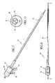
- FIG. 1is a perspective view of a first embodiment of the heat exchange catheter of the present invention.
- FIG. 2is a bottom plan view of the embodiment of FIG. 1 .
- FIG. 3is a cross-sectional view taken along line 3 - 3 of FIG. 2 .
- FIG. 4is an enlarged cross-sectional view of the invention.
- FIG. 5is a sectional view taken along lines 5 - 5 of FIG. 4 .
- FIG. 6is a perspective view of the distal portion of the heat exchange catheter.
- FIG. 7is a perspective view of a second embodiment of the heat exchange catheter of the present invention.
- FIG. 8is a bottom plan view of the embodiment of FIG. 7 .
- FIG. 9is a cross-sectional view taken along line 9 - 9 of FIG. 8 .
- FIG. 10is an enlarged cross-sectional view of the second embodiment of the invention.
- FIG. 11is a sectional view taken along lines 11 - 11 of FIG. 10 .
- FIGS. 1-6illustrate a first embodiment of the heat exchange catheter of the present invention, designated generally as 10 .
- the catheter 10includes an inflow housing assembly, designated generally as 12 and an outflow housing assembly, designated generally as 14 .
- the generally cylindrical housing assemblies 12 , 14are coupled to each other and are serially positioned along a common central axis 16 .
- a flexible outer sleeve 18projects from the distal end of the inflow housing assembly 12 .
- An accessory portion 19 of a multi-lumen tube, designated generally as 20is also positioned along the central axis 16 and extends beyond the end of the outer sleeve 18 .
- the inflow housing assembly 12includes an inflow housing main section 22 and an inflow housing inlet section 24 coupled to the inflow housing main section for providing an inlet flow of warming fluid to the inflow housing main section.
- the inflow housing main section 22 and the inflow housing inlet section 24have respective openings therein for providing for the inlet flow, designated by arrows 26 .
- the inflow housing main section 22 and the inflow housing inlet section 24together comprise an integral, molded plastic part.
- the outflow housing assembly 14includes an outflow housing main section 28 , which is along the central axis 16 of the inflow housing main section 22 .
- the outflow housing main section 28is coupled to the inflow housing main section 22 via a divider element (i.e. flow separator means), designated generally as 30 .
- An outflow housing outlet section 32is coupled to the outflow housing main section 28 for receiving an outlet flow of warming fluid from the outflow housing main section 28 , the outlet flow, designated by arrows 34 .
- the outflow housing main section 28 and the outflow housing outlet section 32have respective openings for the inlet flow 26 and the outlet flow 34 .
- the divider element 30includes a proximal axially oriented portion 36 secured to a proximal end of the inflow housing main section 22 and to a distal end of the outflow housing main section 28 .
- a radially inwardly extending portion 38depends from a distal end of the proximal axially oriented portion 36 .
- the radially inward extending portion 38is radially off center from the central axis 16 .
- a distal axially oriented portion 40depends from the radially inwardly extending portion 38 .
- the distal axially oriented portion 40is secured to a proximal end of an outflow portion 42 of the multi-lumen tube 20 .
- the multi-lumen tube 20 central axis(which is also the central axis of the outflow portion 42 ) is positioned offset from the central axis 16 .
- the inflow housing main section 22includes an axial extension 44 .
- the outer sleeve 18is secured between the outer surface of the axial extension 44 and a strain relief element 48 .
- FIG. 4illustrates the outflow portion 42 of the multi-lumen tube 20 being secured to the inner surface of the distal axially oriented portion 40 it may be secured in other locations such as the outer surface of the distal axially oriented portion 40 .
- a LUER fitting 46extends rearwardly from a proximal end of the outflow housing main section 28 for providing access to the accessory portion 19 .
- the discharge tube 20may provide access for the discharge of bladder fluid or may, for example, provide access for a guide wire or endoscope.
- the outer sleeve 18is preferably made from a flexible, relatively non-stretchable, polyester film such as polyethylene terephthalate (PET), having a fixed diameter upon introduction of fluid therein. Preferably, this diameter is about 22 French, which corresponds to the average diameter of the urethra in adult male humans. (This is an outside diameter of about 0.288 inches.) It may have an inside diameter of about 0.285 inches.
- the length of the outer sleeve 18may be on the order of, for example, from about 12 inches to about 24 inches.
- the accessory portion 19 of the multi-lumen tube 20is integrally formed within an interior volume of the outflow portion 42 .
- Both portions 19 , 14preferably have substantially circular cross-sections.
- the accessory portion 19has a cross-section smaller than the outflow portion 42 .
- the outflow portion 42is offset from the accessory portion 19 such that the outflow portion 42 and the accessory portion 19 are integrally joined at a common wall.
- the space between the outflow portion 42 and the accessory portion 19defines a fluid return passageway and the space within the accessory portion defines an accessory passageway.
- the multi-lumen tube 20may be formed of, for example, a suitable plastic such as polyethylene.
- the outflow portion 42may have an outside diameter of about 0.162 inches and an inside diameter of about 0.148 inches. Therefore, the wall thickness of the outflow portion 42 is about 0.007 inches. Generally, the outflow portion may have a wall thickness in a range of about 0.005-0.009 inches.
- the outflow portion 42is required to be sufficiently rigid so that the inlet flow does not collapse the outflow portion 42 .
- the accessory portionmay, for example, have an outside diameter of about 0.079 inches and an inside diameter of about 0.055 inches. Therefore, the wall thickness of the accessory portion 19 may be, for example, about 0.012 inches. Generally, the accessory portion may have a wall thickness in a range of about 0.009-0.017 inches.
- the multi-lumen tube 20is essentially non-collapsible.
- a strain relief element 48 in the form of a length of heavier gauge plastic tubingis attached to the inflow housing assembly 12 by telescoping a portion of the tubing over the outer surface of barbed axial extension 44 . Strain relief element 48 extends a distance of approximately five centimeters beyond the end of axial extension 44 .
- ablative devicesare inserted into the prostate region of a patient.
- the heat exchange catheter 10operating as a warming catheter, is inserted through the patient's urethra at least to the bladder neck and generally into the bladder.
- Warming fluidis delivered through the catheter 10 during operation of the ablative surgical devices.
- the warming fluidis delivered into the bladder.
- the urethrais warmed by the warming fluid to preserve living tissue thereof.
- the ablative devicesare preferably cryosurgical probes such as manufactured and marketed by Endocare, Inc., of Irvine, Calif. Generally, six cryosurgical probes are used as well as four temperature probes. Alternatively, other ablative devices may be used, for example, radio frequency electrodes, laser fibers, microwave catheters, or high-intensity focused ultrasound. In such instances the heat exchange fluid is cool so as to prevent the urethra from the heating by the ablative elements.
- the inflow housing assembly 12receives heat exchanges fluid from a pump and warmer, which are, in turn, connected to a reservoir.
- the warming fluidshould be supplied at temperatures sufficient so as to not thermally damage the urethra.
- Appropriate fluidsinclude sterile water, physiological saline, and the like and should be such fluids as are biocompatible and physiologically benign in the event of inadvertent rupture of the outer sleeve 18 .
- the warming fluidpasses through the inflow housing assembly 12 , as shown by arrows 26 , and into the inlet fluid passageway formed within the flexible outer sleeve 18 .
- a closed fluid circulation pathis provided as the fluid is returned to the reservoir.
- the countercurrent flow of incoming and outgoing fluidallows the warmer incoming fluid in outer sleeve 18 to warm the cooler outgoing fluid in the multi-lumen tube 20 .
- the thermal exchangeis even along the length of catheter 10 .
- the entire apparatus of the catheter 10may be constructed in larger or smaller sizes as needed depending on the criteria of patient and use. For example, a catheter 10 for use on a child will be smaller than that used on an adult. Similarly, a catheter 10 for use elsewhere in the body may be smaller or larger than that used in the urethra.
- the inflow housing assembly 54includes an inflow housing main section 56 that comprises an inflow block.
- the outflow housing assembly 58includes an outflow housing main section 60 that comprises an outflow block.
- the outflow blockhas an axial extension 62 having a decreased diameter.
- a mating surfaceis formed by the presentation of the axial extension 62 being offset from the central axis 66 .
- An inner radial surface of the axial extension 62is secured to an outer surface of the outflow portion 64 of the multi-lumen tube 68 .
- the outer sleeve 70may be secured to an outer surface of an axial extension 72 of the inflow housing main section 56 , as shown in FIG. 10 . Alternatively, it may be secured to an inner surface of the axial extension 72 .
- a LUER fitting 74is secured to and extends from a proximal end of the outflow housing main section 60 for providing access to an accessory portion 76 of the multi-lumen tube 68 .
- the inflow housing inlet section 78 and outflow housing outlet section 80are separate pieces from their respective main sections 56 , 60 . They are threaded into their positions relative to their associated main sections.
- the flow separation means in this embodimentis the material that forms the blocks 56 , 60 . Inlet fluid passageways and outlet fluid passageways are provided within these blocks.
- This embodimentoperates in the same manner as that described above with respect to the first embodiment with inlet flow, designated by arrows 82 , passing through the inflow housing assembly 54 , around the distal end of the outflow portion 64 as shown by arrows 84 .
- the flowthus becomes an output flow 86 that flows through the outflow housing assembly 58 .
- the examples discussed aboverefer to the use of a warming fluid it is understood that if the ablative devices are for heating rather than for cooling, the heat exchange fluid would be a cooling fluid.
- the heat exchange cathetermay find additional utility in other areas of surgery where thermal treatment of maintenance of tissues is required with or without the capability of drainage.
- an extended length cathetermay be used for thermal treatment within the intestinal tract or the esophagus.
- Shorter versionsmay find utility in other areas such as nasal passages, otic areas, joints, i.e. arthroscopy, or the like, where adjacent tissues may be undergoing cryogenic or other thermal treatment.
- varied forms of the apparatus and methodmay be used in virtually any body cavity where tissues are exposed to thermal extremes and damage to adjacent tissues is to be avoided. They may find particular utility anywhere cryogenic probe devices are being used to destroy and/or remove tumerous growths.
- FIGS. 1-6has fewer parts than the block embodiment of FIGS. 7-11 and therefore has manufacturing advantages. Molding rather than using machined and standard off the shelf components results in cost advantages.
- the block embodiment of FIGS. 7-11has the advantage of obviating up front tooling expenses.
- the reservoir usedis preferably a removable and disposable plastic container, such as an intravenous bag or a rigid container, which may be prepackaged with a fixed volume of sterile fluid, for example one liter.
- sterile fluidfor example one liter.
- Appropriate fluidsinclude sterile water, physiological saline, and the like and should be such fluids as are biocompatible and physiologically benign in the event of inadvertent rupture of the balloons.
- the reservoirincludes two fittings for connection of the inflow housing inlet section and outflow housing outlet section. These fittings may be standard piercable IV bag fittings.
- a heating blockis configured to removably accept and hold reservoir so as to heat the fluid contained therein.
- the heating blockincludes a vertical slot or window, which permits volume indicia on the reservoir to be viewed.
- the heating blockitself may be a simple resistance heating means or an infrared heater or any other suitable heater capable of raising the temperature of the fluid within reservoir to approximately 42 degrees C. Heating the circulation fluid to this level has been found to provide sufficient warmth within the balloons to counter the cold of a cryoprobe and maintain the urethral tissues at about normal body temperature during cryogenic surgery of the prostate. Suitable heater control means allows the operator to select the desired temperature for heater block.
- a pumpDownstream from the heating block is a pump, which provides motive force to the fluid to maintain a constant and even flow through the system.
- automatic control meansare activated to maintain these levels.
- the automatic controlsinclude monitoring sensors for supply temperature, return temperature and flow rate.
- pump and heater activating switchesare included and electrically linked through a control circuit to their respective units as is a low flow alarm.
Landscapes
- Health & Medical Sciences (AREA)
- Vascular Medicine (AREA)
- Animal Behavior & Ethology (AREA)
- Engineering & Computer Science (AREA)
- Biomedical Technology (AREA)
- Heart & Thoracic Surgery (AREA)
- Physics & Mathematics (AREA)
- Life Sciences & Earth Sciences (AREA)
- Thermal Sciences (AREA)
- General Health & Medical Sciences (AREA)
- Public Health (AREA)
- Veterinary Medicine (AREA)
- Thermotherapy And Cooling Therapy Devices (AREA)
- External Artificial Organs (AREA)
- Infusion, Injection, And Reservoir Apparatuses (AREA)
Abstract
Description
Claims (18)
Priority Applications (7)
| Application Number | Priority Date | Filing Date | Title |
|---|---|---|---|
| US11/417,407US7621890B2 (en) | 2005-06-09 | 2006-05-04 | Heat exchange catheter with multi-lumen tube having a fluid return passageway |
| PCT/US2007/067203WO2007130813A2 (en) | 2006-05-04 | 2007-04-23 | Heat exchange catheter with multi-lumen tube having a fluid return passageway |
| CA2649885ACA2649885C (en) | 2006-05-04 | 2007-04-23 | Heat exchange catheter with multi-lumen tube having a fluid return passageway |
| CN2007800159463ACN101437477B (en) | 2006-05-04 | 2007-04-23 | Heat exchange conduit with multilumen tube with liquid return channel |
| EP07761109.3AEP2012721B1 (en) | 2006-05-04 | 2007-04-23 | Heat exchange catheter with multi-lumen tube having a fluid return passageway |
| IL194848AIL194848A (en) | 2006-05-04 | 2008-10-22 | Heat exchange catheter with multi-lumen tube having a fluid return passageway |
| US12/623,283US20100292766A1 (en) | 2005-06-09 | 2009-11-20 | Heat exchange catheter with multi-lumen tube having a fluid return passageway |
Applications Claiming Priority (2)
| Application Number | Priority Date | Filing Date | Title |
|---|---|---|---|
| US11/148,454US7621889B2 (en) | 2005-06-09 | 2005-06-09 | Heat exchange catheter and method of use |
| US11/417,407US7621890B2 (en) | 2005-06-09 | 2006-05-04 | Heat exchange catheter with multi-lumen tube having a fluid return passageway |
Related Parent Applications (1)
| Application Number | Title | Priority Date | Filing Date |
|---|---|---|---|
| US11/148,454Continuation-In-PartUS7621889B2 (en) | 2005-06-09 | 2005-06-09 | Heat exchange catheter and method of use |
Related Child Applications (1)
| Application Number | Title | Priority Date | Filing Date |
|---|---|---|---|
| US12/623,283ContinuationUS20100292766A1 (en) | 2005-06-09 | 2009-11-20 | Heat exchange catheter with multi-lumen tube having a fluid return passageway |
Publications (2)
| Publication Number | Publication Date |
|---|---|
| US20060282039A1 US20060282039A1 (en) | 2006-12-14 |
| US7621890B2true US7621890B2 (en) | 2009-11-24 |
Family
ID=38668438
Family Applications (2)
| Application Number | Title | Priority Date | Filing Date |
|---|---|---|---|
| US11/417,407Active2026-02-07US7621890B2 (en) | 2005-06-09 | 2006-05-04 | Heat exchange catheter with multi-lumen tube having a fluid return passageway |
| US12/623,283AbandonedUS20100292766A1 (en) | 2005-06-09 | 2009-11-20 | Heat exchange catheter with multi-lumen tube having a fluid return passageway |
Family Applications After (1)
| Application Number | Title | Priority Date | Filing Date |
|---|---|---|---|
| US12/623,283AbandonedUS20100292766A1 (en) | 2005-06-09 | 2009-11-20 | Heat exchange catheter with multi-lumen tube having a fluid return passageway |
Country Status (6)
| Country | Link |
|---|---|
| US (2) | US7621890B2 (en) |
| EP (1) | EP2012721B1 (en) |
| CN (1) | CN101437477B (en) |
| CA (1) | CA2649885C (en) |
| IL (1) | IL194848A (en) |
| WO (1) | WO2007130813A2 (en) |
Cited By (11)
| Publication number | Priority date | Publication date | Assignee | Title |
|---|---|---|---|---|
| US9243726B2 (en) | 2012-10-03 | 2016-01-26 | Aarne H. Reid | Vacuum insulated structure with end fitting and method of making same |
| US20160106578A1 (en)* | 2009-02-26 | 2016-04-21 | Advanced Cooling Therapy, Inc. | Devices and methods for controlling patient temperature |
| US10065256B2 (en) | 2015-10-30 | 2018-09-04 | Concept Group Llc | Brazing systems and methods |
| US10413444B2 (en) | 2009-02-26 | 2019-09-17 | Advanced Cooling Therapy, Inc. | Treatment of ischemia-reperfusion injury by controlling patient temperature |
| US10497908B2 (en) | 2015-08-24 | 2019-12-03 | Concept Group, Llc | Sealed packages for electronic and energy storage devices |
| US10723538B2 (en) | 2014-02-20 | 2020-07-28 | Concept Group Llc | Vacuum insulated articles and methods of making same |
| US10823326B2 (en) | 2016-11-15 | 2020-11-03 | Concept Group Llc | Enhanced vacuum-insulated articles with controlled microporous insulation |
| US10835215B2 (en) | 2012-09-12 | 2020-11-17 | Convergent Life Sciences, Inc. | Method and apparatus for laser ablation under ultrasound guidance |
| US11008153B2 (en) | 2016-11-15 | 2021-05-18 | Concept Group Llp | Multiply-insulated assemblies |
| US11320086B2 (en) | 2017-08-25 | 2022-05-03 | Concept Group Llc | Multiple geometry and multiple material insulated components |
| US11702271B2 (en) | 2016-03-04 | 2023-07-18 | Concept Group Llc | Vacuum insulated articles with reflective material enhancement |
Families Citing this family (38)
| Publication number | Priority date | Publication date | Assignee | Title |
|---|---|---|---|---|
| US10363092B2 (en) | 2006-03-24 | 2019-07-30 | Neuwave Medical, Inc. | Transmission line with heat transfer ability |
| US8486127B2 (en)* | 2006-05-24 | 2013-07-16 | Kambiz Dowlatshahi | High temperature thermal therapy of breast cancer |
| US11389235B2 (en) | 2006-07-14 | 2022-07-19 | Neuwave Medical, Inc. | Energy delivery systems and uses thereof |
| US10376314B2 (en) | 2006-07-14 | 2019-08-13 | Neuwave Medical, Inc. | Energy delivery systems and uses thereof |
| US8118803B1 (en)* | 2006-12-19 | 2012-02-21 | Abbott Cardiovascular Systems Inc. | Deflectable catheter assembly |
| CA2684807A1 (en) | 2007-04-05 | 2008-10-16 | Velomedix, Inc. | Automated therapy system and method |
| US20080281200A1 (en)* | 2007-05-10 | 2008-11-13 | Misonix, Incorporated | Elevated coupling liquid temperature during HIFU treatment method and hardware |
| US8380299B2 (en)* | 2007-07-30 | 2013-02-19 | Nuvue Therapeutics, Inc. | Fluid flowing device and method for tissue diagnosis or therapy |
| US8483831B1 (en) | 2008-02-15 | 2013-07-09 | Holaira, Inc. | System and method for bronchial dilation |
| JP2011519699A (en) | 2008-05-09 | 2011-07-14 | インノブアトイブエ プルモナルイ ソルウトイオンス,インコーポレイティッド | Systems, assemblies and methods for treatment of bronchial trees |
| WO2010124109A1 (en) | 2009-04-22 | 2010-10-28 | Nuvue Therapeutics, Inc. | Fluid flowing device and method for tissue diagnosis or therapy |
| EP3549544B1 (en) | 2009-07-28 | 2021-01-06 | Neuwave Medical, Inc. | DEVICE FOR ABLATION |
| WO2011056684A2 (en)* | 2009-10-27 | 2011-05-12 | Innovative Pulmonary Solutions, Inc. | Delivery devices with coolable energy emitting assemblies |
| WO2011060200A1 (en) | 2009-11-11 | 2011-05-19 | Innovative Pulmonary Solutions, Inc. | Systems, apparatuses, and methods for treating tissue and controlling stenosis |
| ES2856026T3 (en) | 2010-05-03 | 2021-09-27 | Neuwave Medical Inc | Power supply systems |
| US9622670B2 (en) | 2010-07-09 | 2017-04-18 | Potrero Medical, Inc. | Method and apparatus for pressure measurement |
| WO2012121786A1 (en)* | 2011-03-09 | 2012-09-13 | Icecure Medical Ltd. | Cryosurgical instrument with redirected flow |
| ES2864589T3 (en) | 2011-04-12 | 2021-10-14 | Thermedical Inc | Devices for conformal therapy in fluid-enhanced ablation |
| US9192438B2 (en) | 2011-12-21 | 2015-11-24 | Neuwave Medical, Inc. | Energy delivery systems and uses thereof |
| US10022176B2 (en) | 2012-08-15 | 2018-07-17 | Thermedical, Inc. | Low profile fluid enhanced ablation therapy devices and methods |
| US20140088457A1 (en)* | 2012-09-26 | 2014-03-27 | Covidien Lp | Bleeding containment device |
| US9610396B2 (en) | 2013-03-15 | 2017-04-04 | Thermedical, Inc. | Systems and methods for visualizing fluid enhanced ablation therapy |
| US9033972B2 (en) | 2013-03-15 | 2015-05-19 | Thermedical, Inc. | Methods and devices for fluid enhanced microwave ablation therapy |
| DE102014013419A1 (en)* | 2014-09-10 | 2016-03-10 | Fresenius Medical Care Deutschland Gmbh | Device comprising a multi-lumen tube |
| US10537465B2 (en)* | 2015-03-31 | 2020-01-21 | Zoll Circulation, Inc. | Cold plate design in heat exchanger for intravascular temperature management catheter and/or heat exchange pad |
| US10022265B2 (en)* | 2015-04-01 | 2018-07-17 | Zoll Circulation, Inc. | Working fluid cassette with hinged plenum or enclosure for interfacing heat exchanger with intravascular temperature management catheter |
| CN113367788B (en) | 2015-10-26 | 2024-09-06 | 纽韦弗医疗设备公司 | Energy delivery systems and uses thereof |
| US10531917B2 (en) | 2016-04-15 | 2020-01-14 | Neuwave Medical, Inc. | Systems and methods for energy delivery |
| US9743984B1 (en) | 2016-08-11 | 2017-08-29 | Thermedical, Inc. | Devices and methods for delivering fluid to tissue during ablation therapy |
| CN106963632A (en)* | 2017-03-06 | 2017-07-21 | 陈国杰 | Hot pin in fluid |
| CN108211095B (en)* | 2018-01-12 | 2023-10-27 | 佛山博骏生物科技有限公司 | Catheter for intravascular sub-low temperature treatment |
| US11672596B2 (en) | 2018-02-26 | 2023-06-13 | Neuwave Medical, Inc. | Energy delivery devices with flexible and adjustable tips |
| US11083871B2 (en) | 2018-05-03 | 2021-08-10 | Thermedical, Inc. | Selectively deployable catheter ablation devices |
| US11918277B2 (en) | 2018-07-16 | 2024-03-05 | Thermedical, Inc. | Inferred maximum temperature monitoring for irrigated ablation therapy |
| CN109528319B (en)* | 2018-12-29 | 2024-06-18 | 天津美电医疗科技有限公司 | Natural cavity protection sleeve |
| US11832879B2 (en) | 2019-03-08 | 2023-12-05 | Neuwave Medical, Inc. | Systems and methods for energy delivery |
| WO2023055551A1 (en)* | 2021-09-29 | 2023-04-06 | Spiral Therapeutics Inc. | Endoscopic systems and methods for treating hearing loss |
| CN115778517A (en)* | 2022-11-14 | 2023-03-14 | 上海导向医疗系统有限公司 | Urethral heat preservation device for intelligent temperature regulation and emergency treatment and emergency treatment method |
Citations (38)
| Publication number | Priority date | Publication date | Assignee | Title |
|---|---|---|---|---|
| US1011606A (en) | 1910-03-05 | 1911-12-12 | Jacob A Fulton | Appliance for subjecting portions of the human system to heat or cold. |
| US3087493A (en) | 1960-04-27 | 1963-04-30 | George W Schossow | Endotracheal tube |
| US4244377A (en) | 1978-10-19 | 1981-01-13 | Grams Guenter A | Ear probe for use in closed-loop caloric irrigation |
| US4813429A (en) | 1986-05-12 | 1989-03-21 | Biodan Medical Systems Ltd. | Catheter and probe |
| US4820349A (en) | 1987-08-21 | 1989-04-11 | C. R. Bard, Inc. | Dilatation catheter with collapsible outer diameter |
| US4823812A (en) | 1986-05-12 | 1989-04-25 | Biodan Medical Systems Ltd. | Applicator for insertion into a body opening for medical purposes |
| US5246421A (en) | 1992-02-12 | 1993-09-21 | Saab Mark A | Method of treating obstructed regions of bodily passages |
| US5248312A (en) | 1992-06-01 | 1993-09-28 | Sensor Electronics, Inc. | Liquid metal-filled balloon |
| US5249585A (en) | 1988-07-28 | 1993-10-05 | Bsd Medical Corporation | Urethral inserted applicator for prostate hyperthermia |
| US5257977A (en) | 1990-03-22 | 1993-11-02 | Argomed Ltd. | Technique for localized thermal treatment of mammals |
| US5264260A (en) | 1991-06-20 | 1993-11-23 | Saab Mark A | Dilatation balloon fabricated from low molecular weight polymers |
| US5342301A (en) | 1992-08-13 | 1994-08-30 | Advanced Polymers Incorporated | Multi-lumen balloons and catheters made therewith |
| US5358486A (en) | 1987-01-09 | 1994-10-25 | C. R. Bard, Inc. | Multiple layer high strength balloon for dilatation catheter |
| US5411477A (en) | 1990-05-11 | 1995-05-02 | Saab; Mark A. | High-strength, thin-walled single piece catheters |
| US5437673A (en)* | 1993-02-04 | 1995-08-01 | Cryomedical Sciences, Inc. | Closed circulation tissue warming apparatus and method of using the same in prostate surgery |
| US5456680A (en) | 1993-09-14 | 1995-10-10 | Spectranetics Corp | Fiber optic catheter with shortened guide wire lumen |
| US5460628A (en) | 1991-01-28 | 1995-10-24 | Neuwirth; Robert S. | Heated balloon medical apparatus with fluid agitating means |
| US5480417A (en) | 1988-11-21 | 1996-01-02 | Technomed Medical Systems | Method and apparatus for the surgical treatment of tissues by thermal effect, and in particular the prostate, using a urethral microwave-emitting probe means |
| US5499973A (en) | 1994-09-08 | 1996-03-19 | Saab; Mark A. | Variable stiffness balloon dilatation catheters |
| US5501227A (en) | 1986-04-15 | 1996-03-26 | Yock; Paul G. | Angioplasty apparatus facilitating rapid exchange and method |
| US5549559A (en) | 1990-03-22 | 1996-08-27 | Argomed Ltd. | Thermal treatment apparatus |
| US5624392A (en) | 1990-05-11 | 1997-04-29 | Saab; Mark A. | Heat transfer catheters and methods of making and using same |
| US5772659A (en) | 1995-09-26 | 1998-06-30 | Valleylab Inc. | Electrosurgical generator power control circuit and method |
| US5827269A (en) | 1996-12-31 | 1998-10-27 | Gynecare, Inc. | Heated balloon having a reciprocating fluid agitator |
| US5843144A (en) | 1995-06-26 | 1998-12-01 | Urologix, Inc. | Method for treating benign prostatic hyperplasia with thermal therapy |
| US6004289A (en) | 1990-05-15 | 1999-12-21 | Medtronic Ave, Inc. | Multiple layer high strength balloon for dilatation catheter |
| US6017361A (en) | 1997-03-13 | 2000-01-25 | Endo Care, Inc. | Urethral warming catheter |
| US6033399A (en) | 1997-04-09 | 2000-03-07 | Valleylab, Inc. | Electrosurgical generator with adaptive power control |
| US6067475A (en) | 1998-11-05 | 2000-05-23 | Urologix, Inc. | Microwave energy delivery system including high performance dual directional coupler for precisely measuring forward and reverse microwave power during thermal therapy |
| US6139571A (en)* | 1997-07-09 | 2000-10-31 | Fuller Research Corporation | Heated fluid surgical instrument |
| US6264679B1 (en) | 1999-08-20 | 2001-07-24 | Radiant Medical, Inc. | Heat exchange catheter with discrete heat exchange elements |
| US6414281B1 (en) | 1999-07-30 | 2002-07-02 | Watlow Electric Manufacturing Company | Hot-toe multicell electric heater |
| US20020177804A1 (en) | 1992-08-13 | 2002-11-28 | Radiant Medical, Inc. | Heat transfer catcheters methods of making and using same |
| US20030055415A1 (en) | 2001-09-20 | 2003-03-20 | Xiaoyu Yu | Malleable cryosurgical probe |
| US6767346B2 (en) | 2001-09-20 | 2004-07-27 | Endocare, Inc. | Cryosurgical probe with bellows shaft |
| US20040167593A1 (en) | 1999-08-20 | 2004-08-26 | Radiant Medical, Inc. | Heat exchange catheter with discrete heat exchange elements |
| WO2004098673A2 (en) | 2003-04-30 | 2004-11-18 | Endocare, Inc. | Closed system warming catheter and method of use |
| US6905494B2 (en)* | 1998-03-31 | 2005-06-14 | Innercool Therapies, Inc. | Method and device for performing cooling- or cryo-therapies for, e.g., angioplasty with reduced restenosis or pulmonary vein cell necrosis to inhibit atrial fibrillation employing tissue protection |
Family Cites Families (4)
| Publication number | Priority date | Publication date | Assignee | Title |
|---|---|---|---|---|
| US6379378B1 (en)* | 2000-03-03 | 2002-04-30 | Innercool Therapies, Inc. | Lumen design for catheter |
| US6141281A (en)* | 1998-04-29 | 2000-10-31 | Enhanced Memory Systems, Inc. | Technique for reducing element disable fuse pitch requirements in an integrated circuit device incorporating replaceable circuit elements |
| US6610083B2 (en)* | 1998-08-24 | 2003-08-26 | Radiant Medical, Inc. | Multiple lumen heat exchange catheters |
| EP1205167B1 (en)* | 1999-02-19 | 2006-10-11 | Alsius Corporation | Central venous line catheter having temperature control system |
- 2006
- 2006-05-04USUS11/417,407patent/US7621890B2/enactiveActive
- 2007
- 2007-04-23EPEP07761109.3Apatent/EP2012721B1/ennot_activeNot-in-force
- 2007-04-23CACA2649885Apatent/CA2649885C/ennot_activeExpired - Fee Related
- 2007-04-23CNCN2007800159463Apatent/CN101437477B/enactiveActive
- 2007-04-23WOPCT/US2007/067203patent/WO2007130813A2/enactiveApplication Filing
- 2008
- 2008-10-22ILIL194848Apatent/IL194848A/enactiveIP Right Grant
- 2009
- 2009-11-20USUS12/623,283patent/US20100292766A1/ennot_activeAbandoned
Patent Citations (50)
| Publication number | Priority date | Publication date | Assignee | Title |
|---|---|---|---|---|
| US1011606A (en) | 1910-03-05 | 1911-12-12 | Jacob A Fulton | Appliance for subjecting portions of the human system to heat or cold. |
| US3087493A (en) | 1960-04-27 | 1963-04-30 | George W Schossow | Endotracheal tube |
| US4244377A (en) | 1978-10-19 | 1981-01-13 | Grams Guenter A | Ear probe for use in closed-loop caloric irrigation |
| US5501227A (en) | 1986-04-15 | 1996-03-26 | Yock; Paul G. | Angioplasty apparatus facilitating rapid exchange and method |
| US4813429A (en) | 1986-05-12 | 1989-03-21 | Biodan Medical Systems Ltd. | Catheter and probe |
| US4823812A (en) | 1986-05-12 | 1989-04-25 | Biodan Medical Systems Ltd. | Applicator for insertion into a body opening for medical purposes |
| US5358486A (en) | 1987-01-09 | 1994-10-25 | C. R. Bard, Inc. | Multiple layer high strength balloon for dilatation catheter |
| US5755690A (en) | 1987-01-09 | 1998-05-26 | C. R. Bard | Multiple layer high strength balloon for dilatation catheter |
| US4820349A (en) | 1987-08-21 | 1989-04-11 | C. R. Bard, Inc. | Dilatation catheter with collapsible outer diameter |
| US5249585A (en) | 1988-07-28 | 1993-10-05 | Bsd Medical Corporation | Urethral inserted applicator for prostate hyperthermia |
| US5480417A (en) | 1988-11-21 | 1996-01-02 | Technomed Medical Systems | Method and apparatus for the surgical treatment of tissues by thermal effect, and in particular the prostate, using a urethral microwave-emitting probe means |
| US5257977A (en) | 1990-03-22 | 1993-11-02 | Argomed Ltd. | Technique for localized thermal treatment of mammals |
| US5549559A (en) | 1990-03-22 | 1996-08-27 | Argomed Ltd. | Thermal treatment apparatus |
| US5411477A (en) | 1990-05-11 | 1995-05-02 | Saab; Mark A. | High-strength, thin-walled single piece catheters |
| US6440158B1 (en) | 1990-05-11 | 2002-08-27 | Mark A. Saab | Heat transfer catheter apparatus and method of making and using same |
| US5624392A (en) | 1990-05-11 | 1997-04-29 | Saab; Mark A. | Heat transfer catheters and methods of making and using same |
| US5902268A (en) | 1990-05-11 | 1999-05-11 | Saab; Mark A. | Heat transfer catheter apparatus and method of making and using same |
| US6004289A (en) | 1990-05-15 | 1999-12-21 | Medtronic Ave, Inc. | Multiple layer high strength balloon for dilatation catheter |
| US5460628A (en) | 1991-01-28 | 1995-10-24 | Neuwirth; Robert S. | Heated balloon medical apparatus with fluid agitating means |
| US5264260A (en) | 1991-06-20 | 1993-11-23 | Saab Mark A | Dilatation balloon fabricated from low molecular weight polymers |
| US5246421A (en) | 1992-02-12 | 1993-09-21 | Saab Mark A | Method of treating obstructed regions of bodily passages |
| US5248312A (en) | 1992-06-01 | 1993-09-28 | Sensor Electronics, Inc. | Liquid metal-filled balloon |
| US20020177804A1 (en) | 1992-08-13 | 2002-11-28 | Radiant Medical, Inc. | Heat transfer catcheters methods of making and using same |
| US20050113893A1 (en) | 1992-08-13 | 2005-05-26 | Radiant Medical, Inc. | Heat transfer catheters and methods of making and using same |
| US20030004456A1 (en) | 1992-08-13 | 2003-01-02 | Saab Mark A. | Multi-lumen heat transfer catheters |
| US20030028212A1 (en) | 1992-08-13 | 2003-02-06 | Saab Mark A. | Multi-lumen catheters and methods for using same |
| US6623516B2 (en)* | 1992-08-13 | 2003-09-23 | Mark A. Saab | Method for changing the temperature of a selected body region |
| US5342301A (en) | 1992-08-13 | 1994-08-30 | Advanced Polymers Incorporated | Multi-lumen balloons and catheters made therewith |
| US6905510B2 (en) | 1992-08-13 | 2005-06-14 | Mark A. Saab | Heat transfer catheters and methods of making and using same |
| US5569195A (en) | 1992-08-13 | 1996-10-29 | Saab; Mark A. | Medical balloon and method of making same |
| US6966889B2 (en) | 1992-08-13 | 2005-11-22 | Saab Mark A | Multi-lumen catheters and methods for using same |
| US5437673A (en)* | 1993-02-04 | 1995-08-01 | Cryomedical Sciences, Inc. | Closed circulation tissue warming apparatus and method of using the same in prostate surgery |
| US5456680A (en) | 1993-09-14 | 1995-10-10 | Spectranetics Corp | Fiber optic catheter with shortened guide wire lumen |
| US5499973A (en) | 1994-09-08 | 1996-03-19 | Saab; Mark A. | Variable stiffness balloon dilatation catheters |
| US5843144A (en) | 1995-06-26 | 1998-12-01 | Urologix, Inc. | Method for treating benign prostatic hyperplasia with thermal therapy |
| US5772659A (en) | 1995-09-26 | 1998-06-30 | Valleylab Inc. | Electrosurgical generator power control circuit and method |
| US5827269A (en) | 1996-12-31 | 1998-10-27 | Gynecare, Inc. | Heated balloon having a reciprocating fluid agitator |
| US6017361A (en) | 1997-03-13 | 2000-01-25 | Endo Care, Inc. | Urethral warming catheter |
| US6419690B1 (en) | 1997-03-13 | 2002-07-16 | Endocare, Inc. | Urethral warming catheter |
| US6033399A (en) | 1997-04-09 | 2000-03-07 | Valleylab, Inc. | Electrosurgical generator with adaptive power control |
| US6139571A (en)* | 1997-07-09 | 2000-10-31 | Fuller Research Corporation | Heated fluid surgical instrument |
| US6905494B2 (en)* | 1998-03-31 | 2005-06-14 | Innercool Therapies, Inc. | Method and device for performing cooling- or cryo-therapies for, e.g., angioplasty with reduced restenosis or pulmonary vein cell necrosis to inhibit atrial fibrillation employing tissue protection |
| US6067475A (en) | 1998-11-05 | 2000-05-23 | Urologix, Inc. | Microwave energy delivery system including high performance dual directional coupler for precisely measuring forward and reverse microwave power during thermal therapy |
| US6414281B1 (en) | 1999-07-30 | 2002-07-02 | Watlow Electric Manufacturing Company | Hot-toe multicell electric heater |
| US6264679B1 (en) | 1999-08-20 | 2001-07-24 | Radiant Medical, Inc. | Heat exchange catheter with discrete heat exchange elements |
| US6702840B2 (en) | 1999-08-20 | 2004-03-09 | Radiant Medical, Inc. | Heat exchange catheter with discrete heat exchange elements |
| US20040167593A1 (en) | 1999-08-20 | 2004-08-26 | Radiant Medical, Inc. | Heat exchange catheter with discrete heat exchange elements |
| US20030055415A1 (en) | 2001-09-20 | 2003-03-20 | Xiaoyu Yu | Malleable cryosurgical probe |
| US6767346B2 (en) | 2001-09-20 | 2004-07-27 | Endocare, Inc. | Cryosurgical probe with bellows shaft |
| WO2004098673A2 (en) | 2003-04-30 | 2004-11-18 | Endocare, Inc. | Closed system warming catheter and method of use |
Non-Patent Citations (3)
| Title |
|---|
| Onik, Cohen, et al. Transrectal Ultrasound-Guided Percutaneous Radical Cryosurgical Ablation of the Prostate, 72 Cancer 1291 (1993). |
| Onik, Ultrasound-Guided Cryosurgery, Scientific American AT 62 (Jan.1996). |
| Wong, et al. Cryosurgery as a Treatment for Prostate Carcinoma, 79 Cancer 963 (Mar. 1997). |
Cited By (21)
| Publication number | Priority date | Publication date | Assignee | Title |
|---|---|---|---|---|
| US10568761B2 (en) | 2009-02-26 | 2020-02-25 | Advanced Cooling Therapy, Inc. | Methods for core body temperature management |
| US20160106578A1 (en)* | 2009-02-26 | 2016-04-21 | Advanced Cooling Therapy, Inc. | Devices and methods for controlling patient temperature |
| US12268631B2 (en) | 2009-02-26 | 2025-04-08 | Advanced Cooling Therapy, Inc. | Devices and methods for protecting esophageal tissue from thermal injury |
| US11633299B2 (en) | 2009-02-26 | 2023-04-25 | Advanced Cooling Therapy, Inc. | Methods for protecting esophageal tissue from thermal injury |
| US10363162B2 (en) | 2009-02-26 | 2019-07-30 | Advanced Cooling Therapy, Inc. | Devices and methods for controlling patient temperature |
| US10413444B2 (en) | 2009-02-26 | 2019-09-17 | Advanced Cooling Therapy, Inc. | Treatment of ischemia-reperfusion injury by controlling patient temperature |
| US10716703B2 (en)* | 2009-02-26 | 2020-07-21 | Advanced Cooling Therapy, Inc. | Devices and methods for controlling patient temperature |
| US10835215B2 (en) | 2012-09-12 | 2020-11-17 | Convergent Life Sciences, Inc. | Method and apparatus for laser ablation under ultrasound guidance |
| US11204127B2 (en) | 2012-10-03 | 2021-12-21 | Concept Group, Llc | Vacuum insulated structure with end fitting and method of making same |
| US10495250B2 (en) | 2012-10-03 | 2019-12-03 | Concept Group, Llc | Vacuum insulated structure with end fitting and method of making same |
| US9243726B2 (en) | 2012-10-03 | 2016-01-26 | Aarne H. Reid | Vacuum insulated structure with end fitting and method of making same |
| US9874303B2 (en) | 2012-10-03 | 2018-01-23 | Aarne H Reid | Vacuum insulated structure with end fitting and method of making same |
| US10723538B2 (en) | 2014-02-20 | 2020-07-28 | Concept Group Llc | Vacuum insulated articles and methods of making same |
| US10497908B2 (en) | 2015-08-24 | 2019-12-03 | Concept Group, Llc | Sealed packages for electronic and energy storage devices |
| US10923691B2 (en) | 2015-08-24 | 2021-02-16 | Concept Group, Llc | Sealed packages for electronic and energy storage devices |
| US10065256B2 (en) | 2015-10-30 | 2018-09-04 | Concept Group Llc | Brazing systems and methods |
| US11702271B2 (en) | 2016-03-04 | 2023-07-18 | Concept Group Llc | Vacuum insulated articles with reflective material enhancement |
| US10823326B2 (en) | 2016-11-15 | 2020-11-03 | Concept Group Llc | Enhanced vacuum-insulated articles with controlled microporous insulation |
| US11008153B2 (en) | 2016-11-15 | 2021-05-18 | Concept Group Llp | Multiply-insulated assemblies |
| US11548717B2 (en) | 2016-11-15 | 2023-01-10 | Concept Group Llc | Multiply-insulated assemblies |
| US11320086B2 (en) | 2017-08-25 | 2022-05-03 | Concept Group Llc | Multiple geometry and multiple material insulated components |
Also Published As
| Publication number | Publication date |
|---|---|
| EP2012721B1 (en) | 2016-04-20 |
| CA2649885A1 (en) | 2007-11-15 |
| US20100292766A1 (en) | 2010-11-18 |
| CN101437477A (en) | 2009-05-20 |
| EP2012721A2 (en) | 2009-01-14 |
| CA2649885C (en) | 2014-09-16 |
| EP2012721A4 (en) | 2010-11-24 |
| WO2007130813A2 (en) | 2007-11-15 |
| CN101437477B (en) | 2011-01-12 |
| US20060282039A1 (en) | 2006-12-14 |
| WO2007130813A3 (en) | 2008-08-21 |
| IL194848A (en) | 2016-07-31 |
| IL194848A0 (en) | 2009-08-03 |
Similar Documents
| Publication | Publication Date | Title |
|---|---|---|
| US7621890B2 (en) | Heat exchange catheter with multi-lumen tube having a fluid return passageway | |
| US6972014B2 (en) | Open system heat exchange catheters and methods of use | |
| US6017361A (en) | Urethral warming catheter | |
| US7621889B2 (en) | Heat exchange catheter and method of use | |
| US5437673A (en) | Closed circulation tissue warming apparatus and method of using the same in prostate surgery | |
| US6726708B2 (en) | Therapeutic heating and cooling via temperature management of a colon-inserted balloon | |
| US6918924B2 (en) | Method and apparatus for regulating patient temperature by irrigating the bladder with a fluid | |
| US5542928A (en) | Method and device for thermal ablation having improved heat transfer | |
| US8323324B2 (en) | Therapeutic heating and cooling via temperature management of a colon-inserted dual balloon | |
| JPH08512226A (en) | Benign prostatic hyperplasia catheter with urethral cooling | |
| EP1357869B1 (en) | Baloon cathether for treatment of a mammalian duct or cavity by pressure or heat | |
| US6893454B2 (en) | Intrarectal heat exchange catheter | |
| US20040220557A1 (en) | Closed system warming catheter and method of use |
Legal Events
| Date | Code | Title | Description |
|---|---|---|---|
| AS | Assignment | Owner name:ENDOCARE, INC., CALIFORNIA Free format text:ASSIGNMENT OF ASSIGNORS INTEREST;ASSIGNORS:DUONG, THACH;EUM, JAY J.;LIU, JENNY C.;REEL/FRAME:017835/0667 Effective date:20060502 | |
| STCF | Information on status: patent grant | Free format text:PATENTED CASE | |
| FEPP | Fee payment procedure | Free format text:PAT HOLDER NO LONGER CLAIMS SMALL ENTITY STATUS, ENTITY STATUS SET TO UNDISCOUNTED (ORIGINAL EVENT CODE: STOL); ENTITY STATUS OF PATENT OWNER: LARGE ENTITY | |
| FPAY | Fee payment | Year of fee payment:4 | |
| AS | Assignment | Owner name:REGIONS BANK, TENNESSEE Free format text:SECURITY AGREEMENT;ASSIGNOR:ENDOCARE, INC.;REEL/FRAME:032372/0077 Effective date:20140203 | |
| AS | Assignment | Owner name:MIDCAP FINANCIAL TRUST, AS ADMINISTRATIVE AGENT, MARYLAND Free format text:SECURITY INTEREST;ASSIGNORS:HEALTHTRONICS, INC.;ENDOCARE, INC.;REEL/FRAME:038063/0201 Effective date:20160308 Owner name:MIDCAP FINANCIAL TRUST, AS ADMINISTRATIVE AGENT, M Free format text:SECURITY INTEREST;ASSIGNORS:HEALTHTRONICS, INC.;ENDOCARE, INC.;REEL/FRAME:038063/0201 Effective date:20160308 | |
| FPAY | Fee payment | Year of fee payment:8 | |
| AS | Assignment | Owner name:ENDOCARE, INC., TEXAS Free format text:RELEASE BY SECURED PARTY;ASSIGNOR:MIDCAP FINANCIAL TRUST, AS ADMINISTRATIVE AGENT;REEL/FRAME:046429/0787 Effective date:20180625 | |
| AS | Assignment | Owner name:HEALTHTRONICS, INC., TEXAS Free format text:RELEASE BY SECURED PARTY;ASSIGNOR:REGIONS BANK;REEL/FRAME:046500/0151 Effective date:20160308 Owner name:ENDOCARE, INC., TEXAS Free format text:RELEASE BY SECURED PARTY;ASSIGNOR:REGIONS BANK;REEL/FRAME:046500/0151 Effective date:20160308 | |
| AS | Assignment | Owner name:VARIAN MEDICAL SYSTEMS, INC., CALIFORNIA Free format text:ASSIGNMENT OF ASSIGNORS INTEREST;ASSIGNOR:ENDOCARE;REEL/FRAME:055739/0294 Effective date:20210308 | |
| MAFP | Maintenance fee payment | Free format text:PAYMENT OF MAINTENANCE FEE, 12TH YEAR, LARGE ENTITY (ORIGINAL EVENT CODE: M1553); ENTITY STATUS OF PATENT OWNER: LARGE ENTITY Year of fee payment:12 |