US7621886B2 - Implantable fluid management system for the removal of excess fluid - Google Patents
Implantable fluid management system for the removal of excess fluidDownload PDFInfo
- Publication number
- US7621886B2 US7621886B2US11/181,539US18153905AUS7621886B2US 7621886 B2US7621886 B2US 7621886B2US 18153905 AUS18153905 AUS 18153905AUS 7621886 B2US7621886 B2US 7621886B2
- Authority
- US
- United States
- Prior art keywords
- pump
- fluid
- electromechanical pump
- bladder
- controller
- Prior art date
- Legal status (The legal status is an assumption and is not a legal conclusion. Google has not performed a legal analysis and makes no representation as to the accuracy of the status listed.)
- Expired - Lifetime
Links
- 239000012530fluidSubstances0.000titleclaimsabstractdescription104
- 238000000034methodMethods0.000claimsdescription33
- 210000003200peritoneal cavityAnatomy0.000claimsdescription30
- 210000001519tissueAnatomy0.000claimsdescription13
- 238000004873anchoringMethods0.000claimsdescription10
- 230000004913activationEffects0.000claimsdescription8
- 230000003213activating effectEffects0.000claimsdescription7
- 230000008878couplingEffects0.000claimsdescription6
- 238000010168coupling processMethods0.000claimsdescription6
- 238000005859coupling reactionMethods0.000claimsdescription6
- 238000007920subcutaneous administrationMethods0.000claimsdescription6
- 238000002513implantationMethods0.000claimsdescription5
- 238000004891communicationMethods0.000claimsdescription3
- 230000000541pulsatile effectEffects0.000claimsdescription3
- 206010003445AscitesDiseases0.000abstractdescription14
- 208000003906hydrocephalusDiseases0.000abstractdescription6
- 206010037423Pulmonary oedemaDiseases0.000abstractdescription2
- 208000005973chronic pericardial effusionDiseases0.000abstractdescription2
- 208000005333pulmonary edemaDiseases0.000abstractdescription2
- 210000003932urinary bladderAnatomy0.000description40
- 238000003780insertionMethods0.000description20
- 230000037431insertionEffects0.000description20
- 230000007246mechanismEffects0.000description17
- 239000000463materialSubstances0.000description14
- 238000007726management methodMethods0.000description13
- 230000001684chronic effectEffects0.000description11
- 210000003567ascitic fluidAnatomy0.000description9
- 238000011282treatmentMethods0.000description9
- 208000015181infectious diseaseDiseases0.000description7
- 238000012546transferMethods0.000description7
- 239000003795chemical substances by applicationSubstances0.000description6
- 238000013461designMethods0.000description6
- 239000003814drugSubstances0.000description6
- 210000002700urineAnatomy0.000description6
- 210000002784stomachAnatomy0.000description5
- 102000004190EnzymesHuman genes0.000description4
- 108090000790EnzymesProteins0.000description4
- 208000005228Pericardial EffusionDiseases0.000description4
- 210000003815abdominal wallAnatomy0.000description4
- 230000003115biocidal effectEffects0.000description4
- 238000000576coating methodMethods0.000description4
- 150000001875compoundsChemical class0.000description4
- 229940079593drugDrugs0.000description4
- 239000000126substanceSubstances0.000description4
- 238000002604ultrasonographyMethods0.000description4
- 210000005166vasculatureAnatomy0.000description4
- 208000002151Pleural effusionDiseases0.000description3
- 230000003187abdominal effectEffects0.000description3
- 239000000853adhesiveSubstances0.000description3
- 230000001070adhesive effectEffects0.000description3
- 230000002924anti-infective effectEffects0.000description3
- 210000001367arteryAnatomy0.000description3
- 210000001175cerebrospinal fluidAnatomy0.000description3
- 210000000056organAnatomy0.000description3
- 238000010992refluxMethods0.000description3
- 229960005475antiinfective agentDrugs0.000description2
- 239000004599antimicrobialSubstances0.000description2
- 230000010065bacterial adhesionEffects0.000description2
- 230000003385bacteriostatic effectEffects0.000description2
- 230000000975bioactive effectEffects0.000description2
- 239000000560biocompatible materialSubstances0.000description2
- 210000001124body fluidAnatomy0.000description2
- 238000009954braidingMethods0.000description2
- 230000000694effectsEffects0.000description2
- 210000005095gastrointestinal systemAnatomy0.000description2
- 210000001035gastrointestinal tractAnatomy0.000description2
- 238000010438heat treatmentMethods0.000description2
- 238000003384imaging methodMethods0.000description2
- 230000003993interactionEffects0.000description2
- 230000007774longtermEffects0.000description2
- 229910052751metalInorganic materials0.000description2
- 239000002184metalSubstances0.000description2
- 150000002739metalsChemical class0.000description2
- 229910001000nickel titaniumInorganic materials0.000description2
- HLXZNVUGXRDIFK-UHFFFAOYSA-Nnickel titaniumChemical compound[Ti].[Ti].[Ti].[Ti].[Ti].[Ti].[Ti].[Ti].[Ti].[Ti].[Ti].[Ni].[Ni].[Ni].[Ni].[Ni].[Ni].[Ni].[Ni].[Ni].[Ni].[Ni].[Ni].[Ni].[Ni]HLXZNVUGXRDIFK-UHFFFAOYSA-N0.000description2
- 239000004033plasticSubstances0.000description2
- 229920003023plasticPolymers0.000description2
- 229920000642polymerPolymers0.000description2
- 230000001737promoting effectEffects0.000description2
- 230000002685pulmonary effectEffects0.000description2
- 238000005086pumpingMethods0.000description2
- 230000002441reversible effectEffects0.000description2
- -1stainless steelsChemical class0.000description2
- 238000001356surgical procedureMethods0.000description2
- 102000009027AlbuminsHuman genes0.000description1
- 108010088751AlbuminsProteins0.000description1
- 241000283690Bos taurusSpecies0.000description1
- 241000282465CanisSpecies0.000description1
- 206010007559Cardiac failure congestiveDiseases0.000description1
- 208000017667Chronic DiseaseDiseases0.000description1
- 241000283073Equus caballusSpecies0.000description1
- 241000282324FelisSpecies0.000description1
- 206010019280Heart failuresDiseases0.000description1
- 206010019663Hepatic failureDiseases0.000description1
- 206010062070Peritonitis bacterialDiseases0.000description1
- 238000012356Product developmentMethods0.000description1
- 229910000831SteelInorganic materials0.000description1
- 238000010521absorption reactionMethods0.000description1
- 229910045601alloyInorganic materials0.000description1
- 239000000956alloySubstances0.000description1
- 210000003484anatomyAnatomy0.000description1
- 210000004369bloodAnatomy0.000description1
- 239000008280bloodSubstances0.000description1
- 210000004204blood vesselAnatomy0.000description1
- 210000000746body regionAnatomy0.000description1
- 210000004556brainAnatomy0.000description1
- 230000010261cell growthEffects0.000description1
- 230000005465channelingEffects0.000description1
- 230000006835compressionEffects0.000description1
- 238000007906compressionMethods0.000description1
- 230000008602contractionEffects0.000description1
- 238000011461current therapyMethods0.000description1
- 239000002934diureticSubstances0.000description1
- 229940030606diureticsDrugs0.000description1
- 230000005672electromagnetic fieldEffects0.000description1
- 238000001125extrusionMethods0.000description1
- 230000003176fibrotic effectEffects0.000description1
- 230000006870functionEffects0.000description1
- 230000006872improvementEffects0.000description1
- 238000010348incorporationMethods0.000description1
- 230000001939inductive effectEffects0.000description1
- 210000002570interstitial cellAnatomy0.000description1
- 238000002697interventional radiologyMethods0.000description1
- 150000002500ionsChemical class0.000description1
- 208000007903liver failureDiseases0.000description1
- 231100000835liver failureToxicity0.000description1
- 238000004519manufacturing processMethods0.000description1
- 210000004379membraneAnatomy0.000description1
- 239000012528membraneSubstances0.000description1
- 238000002324minimally invasive surgeryMethods0.000description1
- 239000000203mixtureSubstances0.000description1
- 238000012986modificationMethods0.000description1
- 230000004048modificationEffects0.000description1
- 238000012544monitoring processMethods0.000description1
- 210000003205muscleAnatomy0.000description1
- 235000015097nutrientsNutrition0.000description1
- 230000001575pathological effectEffects0.000description1
- 230000002572peristaltic effectEffects0.000description1
- 102000004169proteins and genesHuman genes0.000description1
- 108090000623proteins and genesProteins0.000description1
- 230000002787reinforcementEffects0.000description1
- 230000000241respiratory effectEffects0.000description1
- 210000003752saphenous veinAnatomy0.000description1
- 229910001285shape-memory alloyInorganic materials0.000description1
- 239000007787solidSubstances0.000description1
- 241000894007speciesSpecies0.000description1
- 229910001220stainless steelInorganic materials0.000description1
- 239000010959steelSubstances0.000description1
- 230000001960triggered effectEffects0.000description1
- 230000005641tunnelingEffects0.000description1
- 230000002792vascularEffects0.000description1
- 210000001631vena cava inferiorAnatomy0.000description1
- 230000002861ventricularEffects0.000description1
- 230000000007visual effectEffects0.000description1
Images


Classifications
- A—HUMAN NECESSITIES
- A61—MEDICAL OR VETERINARY SCIENCE; HYGIENE
- A61M—DEVICES FOR INTRODUCING MEDIA INTO, OR ONTO, THE BODY; DEVICES FOR TRANSDUCING BODY MEDIA OR FOR TAKING MEDIA FROM THE BODY; DEVICES FOR PRODUCING OR ENDING SLEEP OR STUPOR
- A61M27/00—Drainage appliance for wounds or the like, i.e. wound drains, implanted drains
- A61M27/002—Implant devices for drainage of body fluids from one part of the body to another
- A—HUMAN NECESSITIES
- A61—MEDICAL OR VETERINARY SCIENCE; HYGIENE
- A61M—DEVICES FOR INTRODUCING MEDIA INTO, OR ONTO, THE BODY; DEVICES FOR TRANSDUCING BODY MEDIA OR FOR TAKING MEDIA FROM THE BODY; DEVICES FOR PRODUCING OR ENDING SLEEP OR STUPOR
- A61M1/00—Suction or pumping devices for medical purposes; Devices for carrying-off, for treatment of, or for carrying-over, body-liquids; Drainage systems
- A61M1/14—Dialysis systems; Artificial kidneys; Blood oxygenators ; Reciprocating systems for treatment of body fluids, e.g. single needle systems for hemofiltration or pheresis
- A61M1/28—Peritoneal dialysis ; Other peritoneal treatment, e.g. oxygenation
- A—HUMAN NECESSITIES
- A61—MEDICAL OR VETERINARY SCIENCE; HYGIENE
- A61M—DEVICES FOR INTRODUCING MEDIA INTO, OR ONTO, THE BODY; DEVICES FOR TRANSDUCING BODY MEDIA OR FOR TAKING MEDIA FROM THE BODY; DEVICES FOR PRODUCING OR ENDING SLEEP OR STUPOR
- A61M27/00—Drainage appliance for wounds or the like, i.e. wound drains, implanted drains
- A61M27/002—Implant devices for drainage of body fluids from one part of the body to another
- A61M27/006—Cerebrospinal drainage; Accessories therefor, e.g. valves
- A—HUMAN NECESSITIES
- A61—MEDICAL OR VETERINARY SCIENCE; HYGIENE
- A61M—DEVICES FOR INTRODUCING MEDIA INTO, OR ONTO, THE BODY; DEVICES FOR TRANSDUCING BODY MEDIA OR FOR TAKING MEDIA FROM THE BODY; DEVICES FOR PRODUCING OR ENDING SLEEP OR STUPOR
- A61M39/00—Tubes, tube connectors, tube couplings, valves, access sites or the like, specially adapted for medical use
- A61M39/22—Valves or arrangement of valves
- A61M39/24—Check- or non-return valves
- A—HUMAN NECESSITIES
- A61—MEDICAL OR VETERINARY SCIENCE; HYGIENE
- A61M—DEVICES FOR INTRODUCING MEDIA INTO, OR ONTO, THE BODY; DEVICES FOR TRANSDUCING BODY MEDIA OR FOR TAKING MEDIA FROM THE BODY; DEVICES FOR PRODUCING OR ENDING SLEEP OR STUPOR
- A61M5/00—Devices for bringing media into the body in a subcutaneous, intra-vascular or intramuscular way; Accessories therefor, e.g. filling or cleaning devices, arm-rests
- A61M5/14—Infusion devices, e.g. infusing by gravity; Blood infusion; Accessories therefor
- A61M5/142—Pressure infusion, e.g. using pumps
- A61M5/14244—Pressure infusion, e.g. using pumps adapted to be carried by the patient, e.g. portable on the body
- A61M5/14276—Pressure infusion, e.g. using pumps adapted to be carried by the patient, e.g. portable on the body specially adapted for implantation
- A—HUMAN NECESSITIES
- A61—MEDICAL OR VETERINARY SCIENCE; HYGIENE
- A61M—DEVICES FOR INTRODUCING MEDIA INTO, OR ONTO, THE BODY; DEVICES FOR TRANSDUCING BODY MEDIA OR FOR TAKING MEDIA FROM THE BODY; DEVICES FOR PRODUCING OR ENDING SLEEP OR STUPOR
- A61M39/00—Tubes, tube connectors, tube couplings, valves, access sites or the like, specially adapted for medical use
- A61M39/22—Valves or arrangement of valves
- A61M39/24—Check- or non-return valves
- A61M2039/2473—Valve comprising a non-deformable, movable element, e.g. ball-valve, valve with movable stopper or reciprocating element
- A61M2039/248—Ball-valve
- A—HUMAN NECESSITIES
- A61—MEDICAL OR VETERINARY SCIENCE; HYGIENE
- A61M—DEVICES FOR INTRODUCING MEDIA INTO, OR ONTO, THE BODY; DEVICES FOR TRANSDUCING BODY MEDIA OR FOR TAKING MEDIA FROM THE BODY; DEVICES FOR PRODUCING OR ENDING SLEEP OR STUPOR
- A61M2205/00—General characteristics of the apparatus
- A61M2205/10—General characteristics of the apparatus with powered movement mechanisms
- A61M2205/103—General characteristics of the apparatus with powered movement mechanisms rotating
- A—HUMAN NECESSITIES
- A61—MEDICAL OR VETERINARY SCIENCE; HYGIENE
- A61M—DEVICES FOR INTRODUCING MEDIA INTO, OR ONTO, THE BODY; DEVICES FOR TRANSDUCING BODY MEDIA OR FOR TAKING MEDIA FROM THE BODY; DEVICES FOR PRODUCING OR ENDING SLEEP OR STUPOR
- A61M2205/00—General characteristics of the apparatus
- A61M2205/33—Controlling, regulating or measuring
- A61M2205/3331—Pressure; Flow
- A61M2205/3334—Measuring or controlling the flow rate
- A—HUMAN NECESSITIES
- A61—MEDICAL OR VETERINARY SCIENCE; HYGIENE
- A61M—DEVICES FOR INTRODUCING MEDIA INTO, OR ONTO, THE BODY; DEVICES FOR TRANSDUCING BODY MEDIA OR FOR TAKING MEDIA FROM THE BODY; DEVICES FOR PRODUCING OR ENDING SLEEP OR STUPOR
- A61M2205/00—General characteristics of the apparatus
- A61M2205/33—Controlling, regulating or measuring
- A61M2205/3331—Pressure; Flow
- A61M2205/3355—Controlling downstream pump pressure
- A—HUMAN NECESSITIES
- A61—MEDICAL OR VETERINARY SCIENCE; HYGIENE
- A61M—DEVICES FOR INTRODUCING MEDIA INTO, OR ONTO, THE BODY; DEVICES FOR TRANSDUCING BODY MEDIA OR FOR TAKING MEDIA FROM THE BODY; DEVICES FOR PRODUCING OR ENDING SLEEP OR STUPOR
- A61M2205/00—General characteristics of the apparatus
- A61M2205/82—Internal energy supply devices
- A61M2205/8206—Internal energy supply devices battery-operated
- A—HUMAN NECESSITIES
- A61—MEDICAL OR VETERINARY SCIENCE; HYGIENE
- A61M—DEVICES FOR INTRODUCING MEDIA INTO, OR ONTO, THE BODY; DEVICES FOR TRANSDUCING BODY MEDIA OR FOR TAKING MEDIA FROM THE BODY; DEVICES FOR PRODUCING OR ENDING SLEEP OR STUPOR
- A61M2205/00—General characteristics of the apparatus
- A61M2205/82—Internal energy supply devices
- A61M2205/8237—Charging means
- A—HUMAN NECESSITIES
- A61—MEDICAL OR VETERINARY SCIENCE; HYGIENE
- A61M—DEVICES FOR INTRODUCING MEDIA INTO, OR ONTO, THE BODY; DEVICES FOR TRANSDUCING BODY MEDIA OR FOR TAKING MEDIA FROM THE BODY; DEVICES FOR PRODUCING OR ENDING SLEEP OR STUPOR
- A61M2205/00—General characteristics of the apparatus
- A61M2205/82—Internal energy supply devices
- A61M2205/8275—Mechanical
- A61M2205/8287—Mechanical operated by an external magnetic or electromagnetic field
- A—HUMAN NECESSITIES
- A61—MEDICAL OR VETERINARY SCIENCE; HYGIENE
- A61M—DEVICES FOR INTRODUCING MEDIA INTO, OR ONTO, THE BODY; DEVICES FOR TRANSDUCING BODY MEDIA OR FOR TAKING MEDIA FROM THE BODY; DEVICES FOR PRODUCING OR ENDING SLEEP OR STUPOR
- A61M2210/00—Anatomical parts of the body
- A61M2210/06—Head
- A61M2210/0693—Brain, cerebrum
- A—HUMAN NECESSITIES
- A61—MEDICAL OR VETERINARY SCIENCE; HYGIENE
- A61M—DEVICES FOR INTRODUCING MEDIA INTO, OR ONTO, THE BODY; DEVICES FOR TRANSDUCING BODY MEDIA OR FOR TAKING MEDIA FROM THE BODY; DEVICES FOR PRODUCING OR ENDING SLEEP OR STUPOR
- A61M2210/00—Anatomical parts of the body
- A61M2210/10—Trunk
- A61M2210/101—Pleural cavity
- A—HUMAN NECESSITIES
- A61—MEDICAL OR VETERINARY SCIENCE; HYGIENE
- A61M—DEVICES FOR INTRODUCING MEDIA INTO, OR ONTO, THE BODY; DEVICES FOR TRANSDUCING BODY MEDIA OR FOR TAKING MEDIA FROM THE BODY; DEVICES FOR PRODUCING OR ENDING SLEEP OR STUPOR
- A61M2210/00—Anatomical parts of the body
- A61M2210/10—Trunk
- A61M2210/1017—Peritoneal cavity
- A—HUMAN NECESSITIES
- A61—MEDICAL OR VETERINARY SCIENCE; HYGIENE
- A61M—DEVICES FOR INTRODUCING MEDIA INTO, OR ONTO, THE BODY; DEVICES FOR TRANSDUCING BODY MEDIA OR FOR TAKING MEDIA FROM THE BODY; DEVICES FOR PRODUCING OR ENDING SLEEP OR STUPOR
- A61M2210/00—Anatomical parts of the body
- A61M2210/10—Trunk
- A61M2210/1042—Alimentary tract
- A61M2210/1053—Stomach
- A—HUMAN NECESSITIES
- A61—MEDICAL OR VETERINARY SCIENCE; HYGIENE
- A61M—DEVICES FOR INTRODUCING MEDIA INTO, OR ONTO, THE BODY; DEVICES FOR TRANSDUCING BODY MEDIA OR FOR TAKING MEDIA FROM THE BODY; DEVICES FOR PRODUCING OR ENDING SLEEP OR STUPOR
- A61M2210/00—Anatomical parts of the body
- A61M2210/10—Trunk
- A61M2210/1042—Alimentary tract
- A61M2210/106—Small intestine
- A—HUMAN NECESSITIES
- A61—MEDICAL OR VETERINARY SCIENCE; HYGIENE
- A61M—DEVICES FOR INTRODUCING MEDIA INTO, OR ONTO, THE BODY; DEVICES FOR TRANSDUCING BODY MEDIA OR FOR TAKING MEDIA FROM THE BODY; DEVICES FOR PRODUCING OR ENDING SLEEP OR STUPOR
- A61M2210/00—Anatomical parts of the body
- A61M2210/10—Trunk
- A61M2210/1042—Alimentary tract
- A61M2210/1064—Large intestine
- A—HUMAN NECESSITIES
- A61—MEDICAL OR VETERINARY SCIENCE; HYGIENE
- A61M—DEVICES FOR INTRODUCING MEDIA INTO, OR ONTO, THE BODY; DEVICES FOR TRANSDUCING BODY MEDIA OR FOR TAKING MEDIA FROM THE BODY; DEVICES FOR PRODUCING OR ENDING SLEEP OR STUPOR
- A61M2210/00—Anatomical parts of the body
- A61M2210/10—Trunk
- A61M2210/1078—Urinary tract
- A61M2210/1085—Bladder
- A—HUMAN NECESSITIES
- A61—MEDICAL OR VETERINARY SCIENCE; HYGIENE
- A61M—DEVICES FOR INTRODUCING MEDIA INTO, OR ONTO, THE BODY; DEVICES FOR TRANSDUCING BODY MEDIA OR FOR TAKING MEDIA FROM THE BODY; DEVICES FOR PRODUCING OR ENDING SLEEP OR STUPOR
- A61M2210/00—Anatomical parts of the body
- A61M2210/12—Blood circulatory system
- A61M2210/122—Pericardium
- A—HUMAN NECESSITIES
- A61—MEDICAL OR VETERINARY SCIENCE; HYGIENE
- A61M—DEVICES FOR INTRODUCING MEDIA INTO, OR ONTO, THE BODY; DEVICES FOR TRANSDUCING BODY MEDIA OR FOR TAKING MEDIA FROM THE BODY; DEVICES FOR PRODUCING OR ENDING SLEEP OR STUPOR
- A61M2230/00—Measuring parameters of the user
- A61M2230/005—Parameter used as control input for the apparatus
- A—HUMAN NECESSITIES
- A61—MEDICAL OR VETERINARY SCIENCE; HYGIENE
- A61M—DEVICES FOR INTRODUCING MEDIA INTO, OR ONTO, THE BODY; DEVICES FOR TRANSDUCING BODY MEDIA OR FOR TAKING MEDIA FROM THE BODY; DEVICES FOR PRODUCING OR ENDING SLEEP OR STUPOR
- A61M2230/00—Measuring parameters of the user
- A61M2230/20—Blood composition characteristics
- A61M2230/208—Blood composition characteristics pH-value
- A—HUMAN NECESSITIES
- A61—MEDICAL OR VETERINARY SCIENCE; HYGIENE
- A61M—DEVICES FOR INTRODUCING MEDIA INTO, OR ONTO, THE BODY; DEVICES FOR TRANSDUCING BODY MEDIA OR FOR TAKING MEDIA FROM THE BODY; DEVICES FOR PRODUCING OR ENDING SLEEP OR STUPOR
- A61M2230/00—Measuring parameters of the user
- A61M2230/50—Temperature
- A—HUMAN NECESSITIES
- A61—MEDICAL OR VETERINARY SCIENCE; HYGIENE
- A61M—DEVICES FOR INTRODUCING MEDIA INTO, OR ONTO, THE BODY; DEVICES FOR TRANSDUCING BODY MEDIA OR FOR TAKING MEDIA FROM THE BODY; DEVICES FOR PRODUCING OR ENDING SLEEP OR STUPOR
- A61M5/00—Devices for bringing media into the body in a subcutaneous, intra-vascular or intramuscular way; Accessories therefor, e.g. filling or cleaning devices, arm-rests
- A61M5/14—Infusion devices, e.g. infusing by gravity; Blood infusion; Accessories therefor
- A61M5/168—Means for controlling media flow to the body or for metering media to the body, e.g. drip meters, counters ; Monitoring media flow to the body
- A61M5/172—Means for controlling media flow to the body or for metering media to the body, e.g. drip meters, counters ; Monitoring media flow to the body electrical or electronic
- A61M5/1723—Means for controlling media flow to the body or for metering media to the body, e.g. drip meters, counters ; Monitoring media flow to the body electrical or electronic using feedback of body parameters, e.g. blood-sugar, pressure
Definitions
- the inventionis generally in the field of medical devices. More particularly, it relates to implantable pump-assisted drainage devices, e.g., for transvesicluar drainage, capable of draining fluid from a bodily cavity into another bodily cavity, such as a bladder.
- implantable pump-assisted drainage devicese.g., for transvesicluar drainage, capable of draining fluid from a bodily cavity into another bodily cavity, such as a bladder.
- Chronic pericardial effusions, normopressure hydrocephalus, hydrocephalus, chronic pulmonary effusion, pulmonary edema, and ascitesare but a few of the conditions in which chronic fluid collections persist and result in increased morbidity and mortality.
- asciteswhich is a highly debilitating complication associated with many medical conditions including liver failure and congestive heart failure. Untreated ascites can result in respiratory compromise, compression of the inferior vena cava (a vital blood vessel) and spontaneous bacterial peritonitis (a life-threatening condition). In order to treat chronic ascites, medicine has turned to both drugs and surgery.
- ascitesThe drugs required to treat ascites are typically long-term and frequently result in complications.
- the most common pharmaceutical treatment of ascitesinvolves the use of diuretics to remove fluid from the patient's body through their urine.
- the difficulty with this treatmentis that fluid is removed from the entire body, including the circulating volume of blood, and can result in excessive loss of fluid required to perfuse the vital organs of the human body.
- the medicinesfrequently fail. In such cases, surgical, or invasive, procedures are indicated.
- An implantable fluid management systemmay typically comprise a first tube member having a first end, a second end, and a length which defines a lumen therethrough and having at least one opening at the first end or along the length, a second tube member having a first end, a second end, and a length which defines a lumen therethrough, a pump fluidly coupled to the first tube member and the second tube member for urging fluid through each tube member, and a shunt connected to the second end of the second tube member, wherein the shunt is adapted to anchor the second end of the second tube member to a wall of a hollow body organ in a fluid-tight seal.
- the implantable fluid management systemmay be utilized for chronic excess fluid drainage from one bodily cavity to a second bodily cavity, e.g., a urinary bladder.
- An implantable electromechanically powered and/or magnetically coupled vesicular pumpmay be utilized to permit assisted flow of the excess fluid collections into the bladder. This flow may be directed to be unidirectional through the system.
- the device of the systemmay be used as an ascites drainage device.
- the device of the systemmay be used for peritoneovesicular drainage of the peritoneal fluid from the peritoneal cavity into, e.g., the bladder.
- the drainage of the fluidmay be uni-directional through the system.
- a pump which is fully implantablemay be utilized with the system to transfer excess fluid from a variety of locations in the human body, for instance, the peritoneal cavity, to another region within the body, for instance, the urinary bladder, for the treatment of chronic fluid collections.
- the systemincluding the pump and/or tubular members, may be configured to enable fluid flow in only one direction into, e.g., the bladder, to prevent the reflux of urine or other fluids into the area being drained while still allowing the drainage of the fluid into the bladder.
- This unidirectional configurationmay be achieved through incorporation of a uni-directional valve in the lumen of the tubing or through the use of a uni-directional pump which may also be prevented from being driven in reverse.
- the devicemay include at least two distinct flexible tubular members each defining at least one lumen therethrough.
- One tubular membermay be used for drawing fluid from the region to be drained into or through the pump while the other tube may be used for channeling the fluid from the pump into the hollow body organ such as the bladder.
- the tube for drawing the excess fluid from the body cavitymay contain or define at least one opening, and may preferably define multiple perforations, and/or anti-clogging mechanisms in the region of the fluid intake.
- This tubular membermay also optionally incorporate chemical- or pressure-sensing elements to trigger and/or prevent activation of the pump under specific circumstances.
- the tubular member carrying the pumped fluid to the bladdermay feature an anchoring mechanism such as a shunt mentioned above (e.g., a flange, pigtail coil, etc.) and may optionally be coated with a hydrophilic material to prevent encrustation.
- the tip of this tubingmay also optionally incorporate chemical- or pressure-sensing elements to trigger and/or prevent activation of the pump under specific circumstances ensuring that the pump does not generate excessive bladder pressures.
- These sensorscan be placed anywhere along the length of either tube, including the extremes of a position at the site of pump attachment and a position at the tip of the tubing.
- the two tubescan be integrated together into a single tubular member having two distinct lumens for ease of insertion.
- the shunt for anchoring to the bladder wallmay, in one variation, comprise a hollow, cylindrical column with flanges at either or both ends to provide secure anchorage in the bladder wall.
- the shuntmay have an integrated mechanism to ensure uni-directional flow of fluid while preventing reflux of urine and other fluids back through the shunt.
- One variation of the shuntmay provide a passive ball-valve mechanism which allows for drainage of fluid into the bladder whenever a certain minimum threshold pressure is achieved at the collection site.
- Another variationmay provide an active valve mechanism which allows for controlled drainage of fluid into the bladder whenever the valve is actuated.
- the systemcan be made available in multiple configurations and designs for varying types and severity of fluid collections.
- the tubing connecting the pump to the ventricle of the brainmay be fabricated to be significantly longer than the tubing for chronic ascites which need only reach an adjacent peritoneal cavity.
- the methods of insertion of the fluid management systemmay be based, in part, on the location of the fluid collection.
- the tubular member spanning to the bladder wallmay be placed, e.g., cystoscopically or transabdominally, using minimally invasive procedures.
- the pumpmay be placed subcutaneously using interventional radiology techniques including radiographic imaging such as ultrasound.
- the inflow tubing connected to the pumpin one variation, may be tunneled subcutaneously to the site of drainage and the outflow tubing can be subcutaneously channeled to the bladder.
- the pumpcan be placed in the peritoneal cavity, or other bodily cavity, and activated remotely or set to operate independently based on pressure signals sensed from the fluid.
- the pumpmay be tethered to an inductive charging coil for recharging or, if a battery with sufficient life is used, may carry its own independent power supply.
- the systemmay also optionally include controls to limit the operation of the pump and provide feedback to ensure that the pump is operating correctly. Thus the total fluid flow can be monitored and tightly controlled.
- FIG. 1shows a cross-sectional view of a variation of a shunt device.
- FIG. 2shows a cross-sectional view of an implanted shunt.
- FIG. 3shows a cross-sectional view of the implanted shunt when the peritoneal fluid pressure is insufficient to open the valve.
- FIG. 4shows a cross-sectional view in an illustration of an example of an insertion device within which the shunt can be implanted in the bladder wall.
- FIGS. 5A to 5Cshow alternative variations of the fluid management system with differing valve types, differing valve positioning and differing number of valves.
- FIGS. 6A and 6Bshow cross-sectional illustrations of an alternative variation of the system and a detail view of the shunt, respectively, in which an active, externally, or internally controlled valve is utilized.
- FIG. 7shows a cross-sectional illustration of an alternative variation of the drainage system in which a pump may be included along the length of the tubing.
- FIGS. 8A to 8Cshow illustrations of a few of the alternative variations of the drainage system in which the peritoneal cavity, the pulmonary space, and the ventricular space are able to be drained.
- FIG. 9shows an illustrative magnetically-coupled variation of the drainage system with an illustration of an externally located drive.
- FIGS. 10A to 10Cshow a variation of the drainage system in which the tubes and pump may be removably attachable allowing for increased ease of insertion.
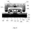
- FIG. 11Ashows an implantable pump variation having removably attachable tubing in the attached position.
- FIG. 11Bshows a variation on an implantable pump which may have its moment forces generated by the pump balanced.
- FIG. 12Ashows a variation of the drainage system having a single dual-lumen tube.
- FIGS. 12B to 12Gshow additional variations of the single dual-lumen tube.
- FIG. 13shows a magnetically-coupled variation of the pump and external drive in which the magnetic interaction is circumferential.
- FIG. 14shows an illustration of an electromechanical variation of the system in which the implanted pump may be rechargeable.
- FIG. 15shows an illustration of an electromechanical variation of the device in which the implanted pump may be placed in a non-subcutaneous position.
- FIGS. 16A to 16Cshow illustration of a few of the possible uses of the drainage system in the drainage of chronic fluid collections in various regions of the body.
- FIG. 17shows a variation of the drainage system which may be fluidly coupled to the vascular system.
- FIG. 18shows another variation of the drainage system which may be coupled to a stomach or another portion of the gastro-intestinal system.
- the implantable fluid management systemmay comprise devices for facilitating the removal of fluid from a body region where drainage is desired.
- the devices disclosed hereinmay be utilized for chronic excess fluid drainage from one bodily cavity to a second bodily cavity, e.g., a urinary bladder.
- An implantable electromechanically powered and/or magnetically coupled vesicular pumpmay be utilized to permit assisted flow of the excess fluid collections into the bladder. This flow may be directed to be uni-directional through the system.
- a vesicular shunt or drain 1may be utilized with the fluid management system for anchoring a tubing member to the wall of a urinary bladder.
- Shunt or drain 1may be implanted in the bladder wall 9 , as shown in FIG. 2 , and can be configured to provide for uni-directional drainage of fluid into the bladder.
- the shunt or drain 1may comprise a flange or projection 2 , 3 at each end of the shunt 1 to facilitate firmly anchoring the shunt 1 across the bladder wall 9 .
- Alternative variations of the shunt 1may utilize other anchoring mechanisms, including, but not limited to, screw threading on the outside of shunt 1 , staples, sutures, adhesive compounds, one or more barbs, etc., and combinations thereof.
- the shunt 1may be configured to define a lumen through the shaft of the device with a valving mechanism positioned within this lumen.
- a ball-valve 4may be positioned to obstruct an inflow opening of the lumen.
- a biasing elementsuch as a spring 5 may be configured to provide a closing pressure against the ball-valve 4 such that the lumen remains shut until a minimum threshold pressure is developed by the fluid which may force the ball-valve 4 open or until a pump is actuated to open the valve 4 .
- the inflow port of the shunt 1may optionally include a porous mesh or filter 6 to allow for the free flow of fluid through shunt 1 while preventing the incarceration of tissues at the drainage site.
- the mesh or filter 6may be configured to filter the fluid through a polymer to sequester components which may be present within the fluid, such as albumin and other proteins, while allowing the flow of fluids and ions across the semi-permeable membrane.
- the peritoneal fluid 19may urge the ball-valve 4 open to then allow fluid flow into the bladder 8 .
- the peritoneal fluid 19may mix with the urine 20 and any other fluids which may be present.
- the ball-valve 4may be urged shut to prevent further fluid flow through the shunt 1 .
- the spring force exerted by the biasing element to shut the valve 4 within the shunt 1may be varied depending upon the amount of fluid flow desired.
- valve 4will remain closed preventing reflux of urine and other fluids back into the peritoneal cavity 7 , as depicted in FIG. 3 .
- the shunt 1may be designed to be deployed transurethrally or transabdominally via an insertion device 10 , such as that depicted in the variation of FIG. 4 .
- Various devicessuch as endoscopes, catheters, introducers, etc., may also be utilized as an insertion device 10 depending upon the patient anatomy and the location where the shunt 1 is to be placed.
- a specially configured insertion device 10may define a cavity or channel within which the shunt 1 may be positioned for deployment within a patient.
- the variation shown in the figuremay incorporate flexible flanges 2 , 3 on one or both ends of the shunt 1 .
- one or both flanges 2 , 3may be configured in a low profile configuration and after delivery, one or both flanges 2 , 3 may be configured to self-expand or reconfigure into a larger configuration. Accordingly, flanges 2 , 3 may optionally be fabricated from spring steels, shape memory alloys and superelastic alloys such as nitinol, etc.
- a tubing member 11may be attached to the inflow port of shunt 1 .
- This tubing member 11may be made such that it is sufficiently long enough to reach the region within the body where excess fluid collects.
- tubing member 11may have a perforated receptacle 12 , as described in further detail below, through which the collected fluid may drain into the tubing 11 .
- Other methods for fluid transportmay include, but are not limited to, conduits, catheters, saphenous arteries or vessels, artificial tubular grafts, etc.
- valves of a variety of different typesmay utilize one or more valves of a variety of different types.
- passively-actuated valvesi.e., valves which are configured to automatically open and close without being actively actuated, such as the ball-valve 4 shown in FIG. 5A and flapper valve 13 as shown in FIG. 5B .
- the flapper type valve 13may be positioned within shunt 1 near the outflow port, as shown in FIG. 5B , or it may also be positioned closer to the inflow port, as shown in FIG. 5C .
- An additional optional valve 14may be incorporated into the tubing member 11 anywhere along the length of tubing 11 .
- the types of valves disclosedare intended to be illustrative and is not intended to be limiting. Other variations of the valves are intended to be within the scope of this disclosure.
- FIG. 6Ashows one variation of an active valve 15 positioned within the lumen of shunt 1 in combination with the tubular member 11 .
- FIG. 6Bshows a cross-sectional side view of the shunt 1 along having the active valve 15 positioned within.
- Active valve 15may be actuatable via a remotely located controller to open and shut upon receiving a signal.
- sensors positioned within the shunt 1 or within the tubing 11may provide a signal to the active valve 15 to open or shut according to the signal.
- an electronic valvemay be configured to become triggered via communication across the tissues of the human body through electromagnetic signals such as radio frequency, microwave, or other electromagnetic frequencies.
- electromagnetic signalssuch as radio frequency, microwave, or other electromagnetic frequencies.
- pressure (patient-applied or otherwise) mechanical, magnetic, or other methods of communicationmay be utilized to signal allowing for drainage only at selected times.
- the valve of the devicecan take many shapes and the device can be manufactured from any of a variety of materials provided that they are biocompatible.
- the fluid management systemmay also be configured to incorporate a pump 16 , as shown in FIG. 7 .
- Pump 16when placed subcutaneously, can be actuated to provide an active pumping mechanism with or without the use of passive or active valves, as described in further detail below.
- Pump 16may be configured as a uni-directional pump to facilitate fluid transfer in a single direction. This uni-directional pump feature may be utilized in place of the valve or in combination with the valves.
- the patientmay optionally perform maneuvers to help increase the pressure of any fluid which may be contained within the body cavity. For instance, the patient may bear down to increase intra-abdominal pressure to facilitate drainage of the peritoneal cavity. Alternatively, the patient may also wear or apply a girdle designed to increase abdominal pressure or apply a urethral catheter to decrease bladder pressure.
- the fluid management systemmay be configured to drain fluid collections from a variety of different regions within the body.
- the shunt 1may be anchored within the bladder wall
- the receptacle 12may be placed, as described above, within the peritoneal cavity as shown in FIG. 8A .
- FIG. 8BAnother example is shown in FIG. 8B where the receptacle 17 may be positioned within the pulmonary space for draining pulmonary effusions
- FIG. 8Cshows an example where the receptacle 18 may be positioned within the cerebrospinal region for draining excess cerbrospinal fluid.
- a receptaclemay be positioned within the pericardial region for draining pericardial effusions.
- the shunt, pump, or tubular devicesmay incorporate one or several anti-infective agents to inhibit the spread of infection between body cavities.
- anti-infective agentswhich may be utilized may include, e.g., bacteriostatic materials, bacteriocidal materials, one or more antibiotic dispensers, antibiotic eluting materials, entrained radioisotopes, heating elements, bioactive plastics, surfaces which encourage epithelialization, and coatings which prevent bacterial adhesion, and combinations thereof.
- the devicesmay also incorporate anti-clogging agents.
- anti-clogging agentsmay include, e.g., active ultrasonic components, an inner and outer sleeve which, when actively agitated through coupling to the pump drive or through a flow driven mechanism, disrupts the inner lumen, surfaces which encourage epithelialization, enzyme eluting materials, enzyme eluting materials which specifically target the proteinaceous components of ascites, enzyme eluting materials which specifically target the proteinaceous and encrustation promoting components of urine, chemical eluting surfaces, an intermittent plunger mechanism, coatings which prevent adhesion of proteinaceous compounds, and combinations thereof.
- the anti-infective and/or anti-clogging agentsmay be infused through the devices via a reservoir contained, for instance, in the pump or in a separate reservoir. Alternatively, the agents may be integrated within or coated upon the surfaces of the various components of the system.
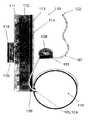
- FIG. 9shows an illustrative detail view of another variation of the system of FIG. 7 above.
- fluidmay be drawn up and carried away by the uptake tube 107 , which in this case, has been perforated to prevent blockage.
- Alternate variationsmay include an uptake screen at the terminus of the uptake tubing member 107 .
- multiple perforations or openingsare shown in tubing member 107 , a single opening may also be defined at the terminal end of the tubing 107 or along the length of the tubing 107 .
- the uptake tubing 107may also include, but is not limited to, conduits, catheters, saphenous arteries or vessels, artificial tubular grafts, etc.
- the tubing 107may be positioned where the excess fluid typically collects within the cavity. Tubing 107 may simply be left within the cavity or it may be anchored to a tissue wall via any number of methods for fastening the tubing 107 , e.g., sutures, staples, clamps, adhesives, etc.
- the uptake tubing 107leads to the pump 101 , which may be used to actively pump or urge the fluid from the uptake tubing 107 and through the outflow tube 108 and into the bladder 110 .
- an optional bladder anchor or shunt 109may be utilized to secure the distal end or portion of outflow tube 108 and prevent detachment of tubing 108 during bladder contraction.
- the bladder anchor or shunt 109may be configured in any one of the variations as described above for the shunt 1 .
- the pump 101can be powered and operated by electromechanical forces or magnetic coupling.
- the pump 101may be placed under the skin 111 in either the subcutaneous space 112 or in the musculature of the abdominal wall 113 .
- the pump 101may be configured as a peristaltic pump, but may also be a gear-pump, turbine-pump, impeller-pump, radial-flow-pump, centrifugal-pump, piston-pump, or any other suitable pump type.
- the pump 101 designensures unidirectional operation.
- the pump 101may be configured to incorporate a pulsatile or oscillating mechanism within the pump 101 to aid in jarring free any materials from collecting or becoming encrusted to thereby prevent the pump 101 or tubing from clogging.
- valvesmay be configured to ensure unidirectional operation.
- the pump 101is preferably enclosed in a housing, shroud or casing 125 made of any suitable biocompatible material.
- the magnetically-coupled driveis also enclosed in the pump housing 125 , in this particular variation, is the magnetically-coupled drive.
- One, two, or more magnets 103may be provided to operate the pump 101 .
- a separate control module 116which is remotely located from the implanted pump 101 may be used to drive external magnets 105 located within the drive unit 102 or magnets 105 may be used to provide an oscillating or alternating electromagnetic field to correspondingly couple through the skin 111 with a magnetic field of the implanted magnets 103 located within the pump 101 .
- the implanted magnets 103are stimulated or urged to move, thereby transferring their kinetic force to operate the pump 101 . While FIG.
- any magnetic field capable of causing or urging the pump magnets 103 to rotatecould be used to operate the pump.
- the pumpmay utilize a gear mechanism whereby the external drive rotates or oscillates two elements in opposite direction thereby canceling any torques generated.
- the pump 101could be electromechanically powered through an implanted battery with external activating and/or monitoring without the requirement for magnetic coupling in which case drive unit 102 may be configured to function as a remote switch for activating the pump 101 .
- One or more sensorsmay be integrated into the implanted pump 103 for detecting a variety of fluid and/or pump parameters. For instance, FIG.
- FIG. 9shows at least one sensor 104 integrated within implanted pump 101 .
- a corresponding sensor 106may be built into the interface of the external drive 102 . Both sensors 104 and 106 may be positioned within their respective units such that when the drive 102 is optimally aligned with implanted pump 101 , the sensors 104 , 106 may indicate to the physician or patient that the pump 101 and drive 102 are optimally engaged and able to efficiently transfer power and/or information.
- the drive 102 or some other indicatormay be used to convey the presence of an optimal engagement to the physician or patient through a variety of methods, for instance, a visual message or indicator signal such as a light or audible signal may be initiated once the sensors 104 , 106 have been aligned.
- These sensors 104 , 106may also transfer information from the pump 101 to the drive 102 , and/or from the drive 102 to the pump 101 , during operation to monitor fluid pressures and/or fluid flows.
- additional magnetscould also be utilized to anchor the pump 101 to the drive 102 against rotational forces generated during the power transfer operation.
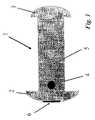
- FIGS. 10A to 10CThe individual implantable components of the system are shown in detail in FIGS. 10A to 10C .
- the outflow tubing 108is shown in one variation in its insertion trocar 117 .
- the bladder anchor 109 and an optional removably attachable port 118which may be designed to couple with an insertion port 120 on the pump 101 .
- FIG. 10Billustrates one variation of the inflow drainage tubing 107 in an insertion trocar 117 with an optional removably attachable port 119 .
- these variationsshow the tubing 107 , 108 positioned within insertion trocars 117 for deployment within a patient, the tubing 107 , 108 may be implanted through various other methods as may be contemplated by one of ordinary skill in the art.
- FIG. 10Cillustrates one variation of the implantable pump 101 with tubing detached.
- the pump 101is illustrated with anchors 121 to resist rotational forces generated with pump use.
- the pump housing 125may be anchored by barbed insertion pins 121 and/or materials designed to promote fibrotic ingrowth for anchoring the pump 101 within the muscle 113 or subcutaneous space 112 .
- Alternative variations of the pump device 101may use other anchoring mechanisms, e.g., screw threading defined on outside surfaces of pump 101 , staples, sutures, adhesive compounds, a porous solid promoting interstitial cell growth, one or more pins designed to be inserted into the abdominal wall, etc., and combinations thereof.
- the tubing 107 , 108 and pump 101are separate components and may placed individually.
- the two tubes 107 , 108may be first inserted through a single incision in the skin and placed in their approximate positions within the patient.
- the pump 101may then be inserted through the incision and attached to both tubes 107 , 108 and secured at the implantation site.
- the tubing 107 , 108may be attached to the pump 101 prior to implantation or during manufacture and the entire system may be implanted as a single system.
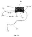
- FIG. 11Aillustrates the pump 101 and tubing 107 , 108 of FIGS. 10A to 10C in which the tubing 107 , 108 has been attached to the corresponding outflow and inflow ports of pump 101 at the junctures of tubing port 118 to pump 120 and tubing port 119 to pump 120 .
- sensors 122 , 124on the ends of the inflow tubing 107 and outflow tubing 108 , respectively.
- sensors 122 , 124may be configured to sense any one of a number of fluid parameters. For instance, one or both sensors 122 , 124 may detect fluid pressures and/or various chemical parameters such as pH of the fluid, or the presence of certain chemicals, etc.
- One or both sensors 122 , 124may also be configured to provide positive and/or negative feedback to the control mechanism, such as the externally located drive unit 102 or an integrated controller located within the pump 101 , in the control of fluid flows.
- the control mechanismsuch as the externally located drive unit 102 or an integrated controller located within the pump 101 , in the control of fluid flows.
- both sensors 122 , 124are shown located at the terminal ends of tubing 107 , 108 , respectively, they may optionally be located anywhere along the lengths of their respective tubes 107 , 108 , if desired or necessary.
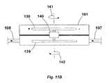
- FIG. 11Bshows a cross-sectional view of another variation of pump 101 which may be utilized to effectively eliminate any excessive movement which may be imparted by torquing forces generated by the pump 101 .
- pump 101After pump 101 has been implanted within a patient, it is generally desirable to inhibit movement of the pump 101 within the body. This may be accomplished through a variety of methods, such as securely anchoring the pump 101 to the surrounding tissue.
- This pump variationmay also be configured to reduce any torque which may be seen by tissues adjacent to the implanted pump 101 . This may be accomplished, in part, by utilizing at least two counter-rotating or counter-oscillating elements within the pump 101 which may rotate or oscillate during pumping such that oppositely generated moments or rotational moments effectively cancel out or balance each other.
- a driver unitsuch as that described above, were activated to rotate element 138 in a first direction, a first rotational moment 141 is generated.
- This moment 141if unbalanced, may impart forces from the pump 101 to the surrounding tissue potentially resulting in damage to the tissue.
- Element 138may be rotationally coupled to a gear box 140 which may be configured to reverse the imparted direction of rotation such that element 139 , which is also rotationally coupled to gear box 140 , is compelled to rotate in an opposite direction from element 138 thus creating a rotational moment 142 .
- the opposite rotational moments 141 , 142may effectively balance or cancel one another such that the net force imparted by the pump 101 to the surrounding tissue is minimized, potentially to a zero load.
- the counter-rotating or counter-oscillating (depending upon the type of pump utilized) elements within a pumpmay be balanced in mass and in configuration in any number of ways to optimize the resulting effect on the pump, depending upon the desired effects.
- FIG. 12Aillustrates one variation of the fluid management system in which both inflow 107 and outflow 108 tubing share a common wall.
- This arrangementmay be utilized ideally for the peritoneal fluid draining design because the bladder 110 and peritoneal cavity 115 share a common wall which facilitates the insertion of a single dual-lumen tube.
- flange 123which can be utilized to prevent insertion of the inflow tubing 107 into the bladder 110 in the case of the single-puncture placement.
- any one of the shunt 1 variations described abovemay be utilized with this variation.
- FIGS. 12B and 12Cshow cross-sectional side and end views, respectively, of the tubing variation of FIG. 12A .
- inflow tubing 107 and outflow tubing 108may share common wall 133 , which may be reinforced to maintain the structural integrity of the tubing.
- the inflow tubing 107may define one or a plurality of openings 134 for drawing the fluid within tubing 107 . Openings 134 may be defined along just a portion of tubing 107 or it may be defined along a majority of the length of tubing 107 depending upon the desired application. In operation, the fluid within the body cavity may be drawn into tubing 107 through openings 134 and drawn into pump 103 .
- FIGS. 12D and 12Eshow another variation of tubing 107 ′ and 108 ′ in which both tubes are formed from a single extrusion 135 .
- tubing 107 ′may define one or a plurality of openings 134 .
- FIGS. 12F and 12Gshow cross-sectional side and end views of yet another variation of a single-tube dual-lumen variation in which outflow tubing 108 ′′ may be coaxially positioned within inflow tubing 107 ′′.
- openings 134may be defined along a length of inflow tubing 107 ′′ while outflow tubing 108 ′′ may remain intact.
- Both inflow and outflow tubing, or just one of the tubes,may be reinforced along a portion of its length of along its entire length. Reinforcement of the tubing may be accomplished via ribbon or wire braiding or lengths of wire or ribbon embedded or integrated within or along the tubing.
- the braiding or wiremay be fabricated from metals such as stainless steels, superelastic metals such as nitinol, or from a variety of suitable polymers.
- FIG. 13illustrates one variation of the pump device in which the magnetic coupling mechanism employed allows for circumferential interaction.
- the pump 101may be implanted under the skin 111 yet close to the surface such that the pump magnets 103 may be positioned within the inner diameter of, and/or in the same plane as, the external drive magnets 105 .
- the arms 127 of the drive unitmay protrude to define a circumferential cavity for receiving the implanted pump 101 and the overlying skin 111 within this channel.
- the design of the holding arms 127may be blunted to prevent excessive pressure from being exerted upon the skin 111 over the site of insertion.
- the driveshaft 126is shown which transfers power to the magnet holding arm 127 of the drive.
- This designcan also employ one or several pump anchors 121 , sensors 104 , 106 and/or other features and combinations of the pump and tubing.
- FIGS. 14 and 15illustrate non-magnetically powered pumps in which the implanted pump may be powered by a battery or other implantable power source.
- the pump 101may communicate with the external interface 116 using radiowave or electromagnetic signal generators and receivers 128 , 129 to transfer information and/or activation signals.
- This pump 101can be placed subcutaneously (as shown in FIG. 14 ) or in any other region suitable for implantation (for instance, the pump 101 of FIG. 15 may be implanted directly within the peritoneal cavity) so long as it can communicate with the external component 116 .
- the pumpcan also be internally controlled using the sensors 122 , 124 to determine when to activate the pump.
- These variationsmay be configured so that the physician or patient may be able to intervene using the external control mechanism 116 in order to prevent the operation of the pump 101 in undesirable circumstances.
- the physician and/or patientmay activate the pump 101 using the external controls 116 at their discretion.
- the controlsmay be easily programmed to incorporate various parameters such as a maximum drainage per day and simple drainage controls such as no drainage when the bladder exceeds a certain pressure.
- the pump 101can also be programmed to be activated under certain circumstances, e.g., once the peritoneal pressure sensor 122 experiences a pressure above a certain threshold.
- the devicemay be designed to drain a variety of different fluid collections including, but not limited to, the excess fluid within the peritoneal cavity, as shown in FIG. 16A , pulmonary effusions, as shown in FIG. 16B , and excessive cerebrospinal fluid, as shown in FIG. 16C .
- These figuresshow the bladder anchor 109 , the outflow tube 108 , the pump 101 , the inflow tube 107 , and the drainage ports for the peritoneal 130 , pleural 131 and cerebrospinal 132 drainage sites, although other variations utilizing different features, such as the single tube, dual-lumen tubing described above may be substituted in further variations.
- drainage from other regions of the body using the system and variations thereofare contemplated, such as application for drainage of pericardial effusions. It is important to note that any feature of the present invention can be incorporated into any these designs.
- the housing, shroud or casing 125 of the pumpcan take many shapes and the pump housing 125 can be manufactured from any of a variety of biocompatible materials.
- the pump housing 125may incorporate anti-infective components or agents in order to prevent the spread of infection between the body cavities.
- anti-infective components or agentsmay include, e.g., bacteriostatic materials, bacteriocidal materials, one or more antibiotic dispensers, antibiotic eluting materials, entrained radioisotopes, heating elements, bioactive plastics, surfaces which encourage epithelialization, coatings which prevent bacterial adhesion, etc., and combinations thereof.
- the devicemay also incorporate anti-clogging components, e.g., active ultrasonic components, surfaces which encourage epithelialization, enzyme eluting materials, chemical eluting surfaces, coatings which prevent adhesion of proteinaceous compounds, etc., and combinations thereof.
- anti-clogging componentse.g., active ultrasonic components, surfaces which encourage epithelialization, enzyme eluting materials, chemical eluting surfaces, coatings which prevent adhesion of proteinaceous compounds, etc., and combinations thereof.
- the devicehas been designed to allow for minimally invasive placement, ideally through the use of non-invasive radiographic imaging tools such as abdominal ultrasound. Placement of the fluid management system may be facilitated by filling the bladder 110 and using ultrasound to locate this space; the outflow tubing 108 can then be placed through a small incision and a simple puncture.
- the inflow tubing 107can also be placed in a similar manner using subcutaneous tunneling of the tubing and ultrasound guidance. Once the tubing has been placed, the outflow tubing 107 and the inflow tubing 108 may then be attached to the pump 101 at the insertion sites. The pump 101 may then be set into its site of implantation (for instance, in the subcutaneous space) after which the wound is closed and allowed to heal.
- FIG. 17shows ouflow tubing 108 fluidly coupled in a fluid-tight seal to the vasculature 136 of the patient.
- the fluid collected through inflow tubing 107may be urged via pump 101 through outflow tubing 108 and passed into the vasculature 136 via an anastomotic connection at one of any number of suitable locations along the vasculature.
- the outflow tubing 108may be a saphenous vein or artery.
- the anastomotic connection between tubing 108 and the vasculatureis preferably a fluid-tight seal and may be accomplished through any variety of methods as known to one of skill in the art.
- FIG. 18shows outflow tubing 108 fluidly connected to a stomach 137 of the patient.
- the collected fluidmay be passed into the stomach 137 through use of the shunt described above or through another anastomotic connection to allow for the absorption of any additional nutrients which may be present in the excess fluid.
- the fluid urged into the stomachmay then be passed through the gastro-intestinal system of the patient and eventually voided from the body.
- outflow tubing 108may alternatively be coupled to other suitable regions of the gastro-intestinal tract, such as regions of the small and large intestinal tracts.
- the deviceWhile the device is primarily contemplated for use in human patients, the invention will also have veterinary uses or product development purposes in equine, bovine, canine, feline, and other mammalian species.
Landscapes
- Health & Medical Sciences (AREA)
- Heart & Thoracic Surgery (AREA)
- Engineering & Computer Science (AREA)
- Biomedical Technology (AREA)
- Public Health (AREA)
- General Health & Medical Sciences (AREA)
- Anesthesiology (AREA)
- Veterinary Medicine (AREA)
- Hematology (AREA)
- Life Sciences & Earth Sciences (AREA)
- Animal Behavior & Ethology (AREA)
- Otolaryngology (AREA)
- Ophthalmology & Optometry (AREA)
- Vascular Medicine (AREA)
- Emergency Medicine (AREA)
- Urology & Nephrology (AREA)
- Neurology (AREA)
- Pulmonology (AREA)
- External Artificial Organs (AREA)
Abstract
Description
Claims (24)
Priority Applications (1)
| Application Number | Priority Date | Filing Date | Title |
|---|---|---|---|
| US11/181,539US7621886B2 (en) | 2002-02-25 | 2005-07-13 | Implantable fluid management system for the removal of excess fluid |
Applications Claiming Priority (6)
| Application Number | Priority Date | Filing Date | Title |
|---|---|---|---|
| US35928702P | 2002-02-25 | 2002-02-25 | |
| US38934602P | 2002-06-18 | 2002-06-18 | |
| US10/369,550US7335179B2 (en) | 2002-02-25 | 2003-02-21 | Vesicular shunt for the drainage of excess fluid |
| US49644103P | 2003-08-21 | 2003-08-21 | |
| US10/700,863US7311690B2 (en) | 2002-02-25 | 2003-11-03 | Implantable fluid management system for the removal of excess fluid |
| US11/181,539US7621886B2 (en) | 2002-02-25 | 2005-07-13 | Implantable fluid management system for the removal of excess fluid |
Related Parent Applications (2)
| Application Number | Title | Priority Date | Filing Date |
|---|---|---|---|
| US10/369,550Continuation-In-PartUS7335179B2 (en) | 2002-02-25 | 2003-02-21 | Vesicular shunt for the drainage of excess fluid |
| US10/700,863ContinuationUS7311690B2 (en) | 2002-02-25 | 2003-11-03 | Implantable fluid management system for the removal of excess fluid |
Publications (2)
| Publication Number | Publication Date |
|---|---|
| US20050273034A1 US20050273034A1 (en) | 2005-12-08 |
| US7621886B2true US7621886B2 (en) | 2009-11-24 |
Family
ID=32738892
Family Applications (8)
| Application Number | Title | Priority Date | Filing Date |
|---|---|---|---|
| US10/700,863Expired - LifetimeUS7311690B2 (en) | 2002-02-25 | 2003-11-03 | Implantable fluid management system for the removal of excess fluid |
| US10/826,237Expired - LifetimeUS7909790B2 (en) | 2002-02-25 | 2004-04-17 | Implantable fluid management system for the removal of excess fluid |
| US11/181,539Expired - LifetimeUS7621886B2 (en) | 2002-02-25 | 2005-07-13 | Implantable fluid management system for the removal of excess fluid |
| US11/198,079Expired - LifetimeUS7195608B2 (en) | 2002-02-25 | 2005-08-04 | Implantable fluid management system for the removal of excess fluid |
| US13/029,069Expired - Fee RelatedUS8517973B2 (en) | 2002-02-25 | 2011-02-16 | Implantable fluid management system for the removal of excess fluid |
| US13/973,981Expired - LifetimeUS8882699B2 (en) | 2002-02-25 | 2013-08-22 | Implantable fluid management system for the removal of excess fluid |
| US13/973,984Expired - Fee RelatedUS9421347B2 (en) | 2002-02-25 | 2013-08-22 | Implantable fluid management system for the removal of excess fluid |
| US15/220,812Expired - LifetimeUS9913968B2 (en) | 2002-02-25 | 2016-07-27 | Implantable fluid management system for the removal of excess fluid |
Family Applications Before (2)
| Application Number | Title | Priority Date | Filing Date |
|---|---|---|---|
| US10/700,863Expired - LifetimeUS7311690B2 (en) | 2002-02-25 | 2003-11-03 | Implantable fluid management system for the removal of excess fluid |
| US10/826,237Expired - LifetimeUS7909790B2 (en) | 2002-02-25 | 2004-04-17 | Implantable fluid management system for the removal of excess fluid |
Family Applications After (5)
| Application Number | Title | Priority Date | Filing Date |
|---|---|---|---|
| US11/198,079Expired - LifetimeUS7195608B2 (en) | 2002-02-25 | 2005-08-04 | Implantable fluid management system for the removal of excess fluid |
| US13/029,069Expired - Fee RelatedUS8517973B2 (en) | 2002-02-25 | 2011-02-16 | Implantable fluid management system for the removal of excess fluid |
| US13/973,981Expired - LifetimeUS8882699B2 (en) | 2002-02-25 | 2013-08-22 | Implantable fluid management system for the removal of excess fluid |
| US13/973,984Expired - Fee RelatedUS9421347B2 (en) | 2002-02-25 | 2013-08-22 | Implantable fluid management system for the removal of excess fluid |
| US15/220,812Expired - LifetimeUS9913968B2 (en) | 2002-02-25 | 2016-07-27 | Implantable fluid management system for the removal of excess fluid |
Country Status (1)
| Country | Link |
|---|---|
| US (8) | US7311690B2 (en) |
Cited By (49)
| Publication number | Priority date | Publication date | Assignee | Title |
|---|---|---|---|---|
| US20080125690A1 (en)* | 2006-09-24 | 2008-05-29 | Delaporte Stephen E | Electroactive polymer actuated cerebrospinal fluid shunt |
| US20090275924A1 (en)* | 2006-04-26 | 2009-11-05 | Eastern Virginia Medical School | Systems and Methods for Monitoring and Controlling Internal Pressure of an Eye or Body Part |
| US7678068B2 (en)* | 2002-12-02 | 2010-03-16 | Gi Dynamics, Inc. | Atraumatic delivery devices |
| US7758535B2 (en) | 2002-12-02 | 2010-07-20 | Gi Dynamics, Inc. | Bariatric sleeve delivery devices |
| US7766861B2 (en) | 2002-12-02 | 2010-08-03 | Gi Dynamics, Inc. | Anti-obesity devices |
| WO2014145370A1 (en)* | 2013-03-15 | 2014-09-18 | Syntheon, Llc | Integrated catheter and powered injector system for use in performing radial angiography |
| US9155609B2 (en) | 2002-12-02 | 2015-10-13 | Gi Dynamics, Inc. | Bariatric sleeve |
| US9237944B2 (en) | 2003-12-09 | 2016-01-19 | Gi Dynamics, Inc. | Intestinal sleeve |
| US9248221B2 (en) | 2014-04-08 | 2016-02-02 | Incuvate, Llc | Aspiration monitoring system and method |
| US9339636B1 (en) | 2012-09-06 | 2016-05-17 | Mubashir H Khan | Subcutaneous fluid pump |
| US9421347B2 (en) | 2002-02-25 | 2016-08-23 | Sequana Medical Ag | Implantable fluid management system for the removal of excess fluid |
| US9433427B2 (en) | 2014-04-08 | 2016-09-06 | Incuvate, Llc | Systems and methods for management of thrombosis |
| US9730822B2 (en) | 2014-04-30 | 2017-08-15 | Lean Medical Technologies, LLC | Gastrointestinal device |
| US9883877B2 (en) | 2014-05-19 | 2018-02-06 | Walk Vascular, Llc | Systems and methods for removal of blood and thrombotic material |
| US10226263B2 (en) | 2015-12-23 | 2019-03-12 | Incuvate, Llc | Aspiration monitoring system and method |
| US10232171B2 (en) | 2003-04-09 | 2019-03-19 | Cochlear Limited | Implant magnet system |
| US10252037B2 (en) | 2011-02-16 | 2019-04-09 | Sequana Medical Ag | Apparatus and methods for treating intracorporeal fluid accumulation |
| US10349982B2 (en) | 2011-11-01 | 2019-07-16 | Nuvasive Specialized Orthopedics, Inc. | Adjustable magnetic devices and methods of using same |
| US10398824B2 (en) | 2004-08-18 | 2019-09-03 | Sequana Medical Nv | Dialysis implant and methods of use |
| US10478232B2 (en) | 2009-04-29 | 2019-11-19 | Nuvasive Specialized Orthopedics, Inc. | Interspinous process device and method |
| US10561440B2 (en) | 2015-09-03 | 2020-02-18 | Vesatek, Llc | Systems and methods for manipulating medical devices |
| US10569003B2 (en) | 2012-02-15 | 2020-02-25 | Sequana Medical Nv | Systems and methods for fluid management |
| US10617453B2 (en) | 2015-10-16 | 2020-04-14 | Nuvasive Specialized Orthopedics, Inc. | Adjustable devices for treating arthritis of the knee |
| US10646262B2 (en) | 2011-02-14 | 2020-05-12 | Nuvasive Specialized Orthopedics, Inc. | System and method for altering rotational alignment of bone sections |
| US10660675B2 (en) | 2010-06-30 | 2020-05-26 | Nuvasive Specialized Orthopedics, Inc. | External adjustment device for distraction device |
| US10702292B2 (en) | 2015-08-28 | 2020-07-07 | Incuvate, Llc | Aspiration monitoring system and method |
| US10716922B2 (en) | 2016-08-26 | 2020-07-21 | Sequana Medical Nv | Implantable fluid management system having clog resistant catheters, and methods of using same |
| US10729470B2 (en) | 2008-11-10 | 2020-08-04 | Nuvasive Specialized Orthopedics, Inc. | External adjustment device for distraction device |
| US10743794B2 (en) | 2011-10-04 | 2020-08-18 | Nuvasive Specialized Orthopedics, Inc. | Devices and methods for non-invasive implant length sensing |
| US10751094B2 (en) | 2013-10-10 | 2020-08-25 | Nuvasive Specialized Orthopedics, Inc. | Adjustable spinal implant |
| US10769244B2 (en) | 2016-08-26 | 2020-09-08 | Sequana Medical Nv | Systems and methods for managing and analyzing data generated by an implantable device |
| US10835290B2 (en) | 2015-12-10 | 2020-11-17 | Nuvasive Specialized Orthopedics, Inc. | External adjustment device for distraction device |
| US10898631B2 (en) | 2017-05-24 | 2021-01-26 | Sequana Medical Nv | Direct sodium removal method, solution and apparatus to reduce fluid overload in heart failure patients |
| US10918425B2 (en) | 2016-01-28 | 2021-02-16 | Nuvasive Specialized Orthopedics, Inc. | System and methods for bone transport |
| US11191579B2 (en) | 2012-10-29 | 2021-12-07 | Nuvasive Specialized Orthopedics, Inc. | Adjustable devices for treating arthritis of the knee |
| US11202707B2 (en) | 2008-03-25 | 2021-12-21 | Nuvasive Specialized Orthopedics, Inc. | Adjustable implant system |
| US11234849B2 (en) | 2006-10-20 | 2022-02-01 | Nuvasive Specialized Orthopedics, Inc. | Adjustable implant and method of use |
| US11246694B2 (en) | 2014-04-28 | 2022-02-15 | Nuvasive Specialized Orthopedics, Inc. | System for informational magnetic feedback in adjustable implants |
| US11357549B2 (en) | 2004-07-02 | 2022-06-14 | Nuvasive Specialized Orthopedics, Inc. | Expandable rod system to treat scoliosis and method of using the same |
| US11439449B2 (en) | 2014-12-26 | 2022-09-13 | Nuvasive Specialized Orthopedics, Inc. | Systems and methods for distraction |
| US11497521B2 (en) | 2008-10-13 | 2022-11-15 | Walk Vascular, Llc | Assisted aspiration catheter system |
| US11510689B2 (en) | 2016-04-06 | 2022-11-29 | Walk Vascular, Llc | Systems and methods for thrombolysis and delivery of an agent |
| US11540847B2 (en) | 2015-10-09 | 2023-01-03 | Incuvate, Llc | Systems and methods for management of thrombosis |
| US11559618B2 (en) | 2017-05-24 | 2023-01-24 | Sequana Medical Nv | Formulations and methods for direct sodium removal in patients having severe renal dysfunction |
| US11612416B2 (en) | 2015-02-19 | 2023-03-28 | Nuvasive Specialized Orthopedics, Inc. | Systems and methods for vertebral adjustment |
| US11653945B2 (en) | 2007-02-05 | 2023-05-23 | Walk Vascular, Llc | Thrombectomy apparatus and method |
| US11678905B2 (en) | 2018-07-19 | 2023-06-20 | Walk Vascular, Llc | Systems and methods for removal of blood and thrombotic material |
| US12171444B2 (en) | 2021-02-15 | 2024-12-24 | Walk Vascular, Llc | Systems and methods for removal of blood and thrombotic material |
| US12274458B2 (en) | 2021-02-15 | 2025-04-15 | Walk Vascular, Llc | Systems and methods for removal of blood and thrombotic material |
Families Citing this family (286)
| Publication number | Priority date | Publication date | Assignee | Title |
|---|---|---|---|---|
| US6450173B1 (en) | 1999-08-12 | 2002-09-17 | Obtech Medical Ag | Heartburn and reflux disease treatment with controlled wireless energy supply |
| US6464628B1 (en) | 1999-08-12 | 2002-10-15 | Obtech Medical Ag | Mechanical anal incontinence |
| US6471635B1 (en) | 2000-02-10 | 2002-10-29 | Obtech Medical Ag | Anal incontinence disease treatment with controlled wireless energy supply |
| US6482145B1 (en) | 2000-02-14 | 2002-11-19 | Obtech Medical Ag | Hydraulic anal incontinence treatment |
| ATE391468T1 (en) | 2000-02-10 | 2008-04-15 | Potencia Medical Ag | MECHANICAL DEVICE FOR IMPOTENCY TREATMENT |
| AU764705B2 (en)* | 2000-02-10 | 2003-08-28 | Implantica Patent Ltd. | Urinary incontinence treatment with wireless energy supply |
| CA2635435C (en) | 2000-02-10 | 2010-05-25 | Potencia Medical Ag | Controlled urinary incontinence treatment |
| ATE416743T1 (en) | 2000-02-11 | 2008-12-15 | Potentica Ag | DEVICE WITH ENERGY CONVERSION MEANS FOR TREATING IMPOTENCY |
| US7442165B2 (en) | 2000-02-14 | 2008-10-28 | Obtech Medical Ag | Penile prosthesis |
| US20030100929A1 (en) | 2000-02-14 | 2003-05-29 | Peter Forsell | Controlled penile prosthesis |
| WO2001047440A2 (en) | 2000-02-14 | 2001-07-05 | Potencia Medical Ag | Male impotence prosthesis apparatus with wireless energy supply |
| US8091556B2 (en)* | 2001-04-20 | 2012-01-10 | V-Wave Ltd. | Methods and apparatus for reducing localized circulatory system pressure |
| CA2477054C (en)* | 2002-02-25 | 2011-05-31 | Daniel R. Burnett | Vesicular shunt for the drainage of excess fluid |
| US9694166B2 (en) | 2002-03-26 | 2017-07-04 | Medtronics Ps Medical, Inc. | Method of draining cerebrospinal fluid |
| US20030216710A1 (en)* | 2002-03-26 | 2003-11-20 | Hurt Robert F. | Catheter |
| EP1490148A2 (en) | 2002-04-01 | 2004-12-29 | Med-El Elektromedizinische Geräte GmbH | Reducing effect of magnetic and electromagnetic fields on an implants magnet and/or electronic |
| JP2006517850A (en)* | 2003-02-18 | 2006-08-03 | メドトロニック・インコーポレーテッド | Occlusion resistant hydrocephalus shunt |
| US20080119703A1 (en) | 2006-10-04 | 2008-05-22 | Mark Brister | Analyte sensor |
| US20190357827A1 (en) | 2003-08-01 | 2019-11-28 | Dexcom, Inc. | Analyte sensor |
| US9135402B2 (en) | 2007-12-17 | 2015-09-15 | Dexcom, Inc. | Systems and methods for processing sensor data |
| US7591801B2 (en) | 2004-02-26 | 2009-09-22 | Dexcom, Inc. | Integrated delivery device for continuous glucose sensor |
| US8626257B2 (en) | 2003-08-01 | 2014-01-07 | Dexcom, Inc. | Analyte sensor |
| US8886273B2 (en) | 2003-08-01 | 2014-11-11 | Dexcom, Inc. | Analyte sensor |
| US7920906B2 (en) | 2005-03-10 | 2011-04-05 | Dexcom, Inc. | System and methods for processing analyte sensor data for sensor calibration |
| US8038639B2 (en) | 2004-11-04 | 2011-10-18 | Baxter International Inc. | Medical fluid system with flexible sheeting disposable unit |
| US9247900B2 (en) | 2004-07-13 | 2016-02-02 | Dexcom, Inc. | Analyte sensor |
| US8636721B2 (en) | 2003-11-20 | 2014-01-28 | Henry M. Jackson Foundation For The Advancement Of Military Medicine, Inc. | Portable hand pump for evacuation of fluids |
| US8364230B2 (en) | 2006-10-04 | 2013-01-29 | Dexcom, Inc. | Analyte sensor |
| US8425417B2 (en) | 2003-12-05 | 2013-04-23 | Dexcom, Inc. | Integrated device for continuous in vivo analyte detection and simultaneous control of an infusion device |
| US8287453B2 (en) | 2003-12-05 | 2012-10-16 | Dexcom, Inc. | Analyte sensor |
| US8364231B2 (en) | 2006-10-04 | 2013-01-29 | Dexcom, Inc. | Analyte sensor |
| US8423114B2 (en) | 2006-10-04 | 2013-04-16 | Dexcom, Inc. | Dual electrode system for a continuous analyte sensor |
| US11633133B2 (en) | 2003-12-05 | 2023-04-25 | Dexcom, Inc. | Dual electrode system for a continuous analyte sensor |
| US8425416B2 (en) | 2006-10-04 | 2013-04-23 | Dexcom, Inc. | Analyte sensor |
| JP2007527742A (en) | 2004-02-03 | 2007-10-04 | アトリア メディカル インク | Apparatus and method for controlling pressure in a living body |
| WO2009048462A1 (en) | 2007-10-09 | 2009-04-16 | Dexcom, Inc. | Integrated insulin delivery system with continuous glucose sensor |
| US8808228B2 (en) | 2004-02-26 | 2014-08-19 | Dexcom, Inc. | Integrated medicament delivery device for use with continuous analyte sensor |
| US7783333B2 (en) | 2004-07-13 | 2010-08-24 | Dexcom, Inc. | Transcutaneous medical device with variable stiffness |
| US8886272B2 (en) | 2004-07-13 | 2014-11-11 | Dexcom, Inc. | Analyte sensor |
| US20070045902A1 (en) | 2004-07-13 | 2007-03-01 | Brauker James H | Analyte sensor |
| US7654956B2 (en) | 2004-07-13 | 2010-02-02 | Dexcom, Inc. | Transcutaneous analyte sensor |
| JP4964771B2 (en)* | 2004-07-20 | 2012-07-04 | メドトロニック,インコーポレイテッド | Cerebrospinal fluid drainage device |
| US8337475B2 (en) | 2004-10-12 | 2012-12-25 | C. R. Bard, Inc. | Corporeal drainage system |
| US7585280B2 (en) | 2004-12-29 | 2009-09-08 | Codman & Shurtleff, Inc. | System and method for measuring the pressure of a fluid system within a patient |
| US20080097277A1 (en)* | 2005-02-22 | 2008-04-24 | Saunders Richard L | Controllable Shunt |
| US10362947B2 (en)* | 2005-03-15 | 2019-07-30 | Integra LifeSciences Switzerland Sarl | Pressure sensing devices |
| US7510533B2 (en)* | 2005-03-15 | 2009-03-31 | Codman & Shurtleff, Inc. | Pressure sensing valve |
| US20060211945A1 (en)* | 2005-03-15 | 2006-09-21 | Codman & Shurtleff, Inc. | Pressure sensing methods |
| US20060235349A1 (en)* | 2005-04-14 | 2006-10-19 | Brett Osborn | Implantable anti-clogging device for maintenance of cerebrospinal fluid shunt patency |
| US8068910B2 (en)* | 2005-04-28 | 2011-11-29 | Medtronic, Inc. | Flexible tube sensor for sensing urinary sphincter pressure |
| US7623923B2 (en)* | 2005-04-28 | 2009-11-24 | Medtronic, Inc. | Tube sensor for penile tumescence |
| US7610093B2 (en)* | 2005-04-28 | 2009-10-27 | Medtronic, Inc. | Implantable optical pressure sensor for sensing urinary sphincter pressure |
| US7328070B2 (en)* | 2005-04-28 | 2008-02-05 | Medtronic, Inc. | Multi-tube sensor for sensing urinary sphincter and urethral pressure |
| US8002730B2 (en)* | 2005-04-29 | 2011-08-23 | Medtronic, Inc. | Anti-thrombogenic venous shunt system and method |
| US20080281250A1 (en)* | 2005-05-10 | 2008-11-13 | Marvin Bergsneider | Self-Clearing Catheter for Clinical Implantation |
| US20070038171A1 (en)* | 2005-07-25 | 2007-02-15 | Mayer Peter L | Shunt system |
| US8177772B2 (en) | 2005-09-26 | 2012-05-15 | C. R. Bard, Inc. | Catheter connection systems |
| US8328792B2 (en) | 2005-10-27 | 2012-12-11 | C. R. Bard, Inc. | Enhanced pre-wetted intermittent catheter with lubricious coating |
| WO2007083288A2 (en) | 2006-01-23 | 2007-07-26 | Atria Medical Inc. | Heart anchor device |
| WO2007092875A2 (en)* | 2006-02-09 | 2007-08-16 | Pizzi Francis J | Dual channel shunt device and method for ventriculo-peritoneal shunting of bloody cerebrospinal fluid |
| US20070255176A1 (en)* | 2006-04-28 | 2007-11-01 | Medtronic, Inc. | Voiding detection with learning mode |
| US7522061B2 (en) | 2006-04-28 | 2009-04-21 | Medtronic, Inc. | External voiding sensor system |
| US7855653B2 (en)* | 2006-04-28 | 2010-12-21 | Medtronic, Inc. | External voiding sensor system |
| US8298142B2 (en) | 2006-10-04 | 2012-10-30 | Dexcom, Inc. | Analyte sensor |
| US8449464B2 (en) | 2006-10-04 | 2013-05-28 | Dexcom, Inc. | Analyte sensor |
| US8478377B2 (en) | 2006-10-04 | 2013-07-02 | Dexcom, Inc. | Analyte sensor |
| US8562528B2 (en) | 2006-10-04 | 2013-10-22 | Dexcom, Inc. | Analyte sensor |
| US8447376B2 (en) | 2006-10-04 | 2013-05-21 | Dexcom, Inc. | Analyte sensor |
| US8275438B2 (en) | 2006-10-04 | 2012-09-25 | Dexcom, Inc. | Analyte sensor |
| US20100254830A1 (en)* | 2006-10-10 | 2010-10-07 | Beebe David J | Magnetically driven micro-pumping method using external rotating stirrer |
| CA2668077C (en) | 2006-10-31 | 2015-12-29 | Novashunt Ag | An implantable fluid management device for the removal of excess fluid |
| US20080234638A1 (en)* | 2007-03-24 | 2008-09-25 | David Christopher Antonio | Valves, Valved Fluid Transfer Devices and Ambulatory Infusion Devices Including The Same |
| CA2684807A1 (en) | 2007-04-05 | 2008-10-16 | Velomedix, Inc. | Automated therapy system and method |
| US9072866B2 (en) | 2007-04-13 | 2015-07-07 | Neuro Diagnostic Devices, Inc. | Cerebrospinal fluid evaluation system having thermal flow and flow rate measurement pad using a plurality of control sensors |
| GB2449296A (en)* | 2007-05-17 | 2008-11-19 | Centrax Ltd | Device for diverting fluid |
| WO2008154312A1 (en) | 2007-06-08 | 2008-12-18 | Dexcom, Inc. | Integrated medicament delivery device for use with continuous analyte sensor |
| US8366652B2 (en)* | 2007-08-17 | 2013-02-05 | The Invention Science Fund I, Llc | Systems, devices, and methods including infection-fighting and monitoring shunts |
| US20110160644A1 (en)* | 2007-08-17 | 2011-06-30 | Searete Llc, A Limited Liability Corporation Of The State Of Delaware | Systems, devices, and methods including catheters configured to release ultraviolet energy absorbing agents |
| US8029740B2 (en)* | 2008-07-11 | 2011-10-04 | The Invention Science Fund I, Llc | Event-triggered self-sterilization of article surfaces |
| US8460229B2 (en) | 2007-08-17 | 2013-06-11 | The Invention Science Fund I, Llc | Systems, devices, and methods including catheters having components that are actively controllable between transmissive and reflective states |
| US20090048648A1 (en)* | 2007-08-17 | 2009-02-19 | Searete Llc, A Limited Liability Corporation Of The State Of Delaware | Self-sterilizing device |
| US8706211B2 (en) | 2007-08-17 | 2014-04-22 | The Invention Science Fund I, Llc | Systems, devices, and methods including catheters having self-cleaning surfaces |
| US8114346B2 (en)* | 2007-08-17 | 2012-02-14 | The Invention Science Fund I, Llc | Event-triggered ultraviolet light sterilization of surfaces |
| US20090163964A1 (en)* | 2007-08-17 | 2009-06-25 | Searete Llc, A Limited Liability Corporation Of The State Of Delaware | System, devices, and methods including sterilizing excitation delivery implants with general controllers and onboard power |
| US8734718B2 (en)* | 2007-08-17 | 2014-05-27 | The Invention Science Fund I, Llc | Systems, devices, and methods including catheters having an actively controllable therapeutic agent delivery component |
| US8162924B2 (en) | 2007-08-17 | 2012-04-24 | The Invention Science Fund I, Llc | System, devices, and methods including actively-controllable superoxide water generating systems |
| US8647292B2 (en)* | 2007-08-17 | 2014-02-11 | The Invention Science Fund I, Llc | Systems, devices, and methods including catheters having components that are actively controllable between two or more wettability states |
| US8753304B2 (en)* | 2007-08-17 | 2014-06-17 | The Invention Science Fund I, Llc | Systems, devices, and methods including catheters having acoustically actuatable waveguide components for delivering a sterilizing stimulus to a region proximate a surface of the catheter |
| US20090177254A1 (en)* | 2007-08-17 | 2009-07-09 | Searete Llc, A Limited Liability Of The State Of The State Of Delaware | System, devices, and methods including actively-controllable electrostatic and electromagnetic sterilizing excitation delivery system |
| US8702640B2 (en)* | 2007-08-17 | 2014-04-22 | The Invention Science Fund I, Llc | System, devices, and methods including catheters configured to monitor and inhibit biofilm formation |
| US8417312B2 (en) | 2007-10-25 | 2013-04-09 | Dexcom, Inc. | Systems and methods for processing sensor data |
| US20090112262A1 (en) | 2007-10-30 | 2009-04-30 | Scott Pool | Skeletal manipulation system |
| US9204812B2 (en) | 2007-10-31 | 2015-12-08 | DePuy Synthes Products, LLC | Wireless pressure sensing shunts |
| US8480612B2 (en)* | 2007-10-31 | 2013-07-09 | DePuy Synthes Products, LLC | Wireless shunts with storage |
| US8454524B2 (en) | 2007-10-31 | 2013-06-04 | DePuy Synthes Products, LLC | Wireless flow sensor |
| US7842004B2 (en)* | 2007-10-31 | 2010-11-30 | Codman & Shurtleff, Inc. | Wireless pressure setting indicator |
| US8419638B2 (en)* | 2007-11-19 | 2013-04-16 | Proteus Digital Health, Inc. | Body-associated fluid transport structure evaluation devices |
| US8290559B2 (en) | 2007-12-17 | 2012-10-16 | Dexcom, Inc. | Systems and methods for processing sensor data |
| WO2009096851A1 (en)* | 2008-01-28 | 2009-08-06 | Milux Holding Sa | A drainage device comprising a filter cleaning device |
| WO2009096854A1 (en)* | 2008-01-28 | 2009-08-06 | Milux Holding Sa | An implantable fluid movement device |
| MX2010008003A (en) | 2008-01-29 | 2010-09-24 | Milux Holding Sa | Apparatus for treating obesity. |
| US8396528B2 (en) | 2008-03-25 | 2013-03-12 | Dexcom, Inc. | Analyte sensor |
| US8192371B2 (en)* | 2008-03-31 | 2012-06-05 | The Invention Science Fund I, Llc | Systems and methods for obtaining analytes from a body |
| US8211053B2 (en)* | 2008-05-13 | 2012-07-03 | Equilibrate, Llc | Interosmolar fluid removal |
| US8608739B2 (en)* | 2008-07-22 | 2013-12-17 | Covidien Lp | Electrosurgical devices, systems and methods of using the same |
| US9078964B2 (en)* | 2008-08-21 | 2015-07-14 | Sur-Real Industries, Inc. | Pump device, tube device and method for movement and collection of fluid |
| US20100152608A1 (en)* | 2008-09-12 | 2010-06-17 | Hatlestad John D | Chronically implanted abdominal pressure sensor for continuous ambulatory assessment of renal functions |
| WO2010042046A1 (en) | 2008-10-10 | 2010-04-15 | Milux Holding S.A. | Apparatus, system and operation method for the treatment of female sexual dysfunction |
| EP2344106B8 (en)* | 2008-10-10 | 2022-07-20 | MedicalTree Patent Ltd. | Heart help device |
| WO2010042018A1 (en) | 2008-10-10 | 2010-04-15 | Milux Holding S.A. | Heart help device, system and method |
| US10668196B2 (en)* | 2008-10-10 | 2020-06-02 | Peter Forsell | Heart assisting device |
| EP3851076A1 (en) | 2008-10-10 | 2021-07-21 | MedicalTree Patent Ltd. | An improved artificial valve |
| WO2010042011A1 (en)* | 2008-10-10 | 2010-04-15 | Milux Holding Sa | Heart help device, system, and method |
| AU2009302955B2 (en) | 2008-10-10 | 2017-01-05 | Implantica Patent Ltd. | Fastening means for implantable medical control assembly |
| EP2349095B1 (en)* | 2008-10-10 | 2023-06-07 | MedicalTree Patent Ltd. | An improved artifical valve |
| US8475355B2 (en)* | 2008-10-10 | 2013-07-02 | Milux Holding S.A. | Heart help device, system, and method |
| HUE055585T2 (en)* | 2008-10-10 | 2021-12-28 | Implantica Patent Ltd | Implantable device for internal urinary control |
| US20210378811A1 (en)* | 2008-10-10 | 2021-12-09 | Peter Forsell | Fastening means for implantable medical control assembly |
| US11660430B2 (en)* | 2008-10-10 | 2023-05-30 | Peter Forsell | Heart assisting device |
| EP2349384B1 (en)* | 2008-10-10 | 2021-03-17 | MedicalTree Patent Ltd. | Heart help device system |
| US8874215B2 (en) | 2008-10-10 | 2014-10-28 | Peter Forsell | System, an apparatus, and a method for treating a sexual dysfunctional female patient |
| US8585627B2 (en)* | 2008-12-04 | 2013-11-19 | The Invention Science Fund I, Llc | Systems, devices, and methods including catheters configured to monitor biofilm formation having biofilm spectral information configured as a data structure |
| US20120041285A1 (en) | 2008-12-04 | 2012-02-16 | Searete Llc, A Limited Liability Corporation Of The State Of Delaware | Systems, devices, and methods including implantable devices with anti-microbial properties |
| US20110152751A1 (en)* | 2008-12-04 | 2011-06-23 | Searete Llc, A Limited Liability Corporation Of The State Of Delaware | Systems, devices, and methods including catheters having UV-Energy emitting coatings |
| EP2384168B1 (en)* | 2008-12-04 | 2014-10-08 | Searete LLC | Actively-controllable sterilizing excitation delivery implants |
| US9572921B2 (en)* | 2008-12-17 | 2017-02-21 | Smith & Nephew, Inc. | Cartridge assembly |
| US8197490B2 (en) | 2009-02-23 | 2012-06-12 | Ellipse Technologies, Inc. | Non-invasive adjustable distraction system |
| US8088091B2 (en) | 2009-03-09 | 2012-01-03 | New Jersey Institute Of Technology | No clog shunt using a compact fluid drag path |
| US9034034B2 (en) | 2010-12-22 | 2015-05-19 | V-Wave Ltd. | Devices for reducing left atrial pressure, and methods of making and using same |
| US12186176B2 (en) | 2009-05-04 | 2025-01-07 | V-Wave Ltd. | Shunt for redistributing atrial blood volume |
| WO2010128501A1 (en) | 2009-05-04 | 2010-11-11 | V-Wave Ltd. | Device and method for regulating pressure in a heart chamber |
| US10076403B1 (en) | 2009-05-04 | 2018-09-18 | V-Wave Ltd. | Shunt for redistributing atrial blood volume |
| US20210161637A1 (en) | 2009-05-04 | 2021-06-03 | V-Wave Ltd. | Shunt for redistributing atrial blood volume |
| US7967797B2 (en)* | 2009-05-19 | 2011-06-28 | Nexus Medical, Llc | Intravascular valve component with improved valve positioning |
| US10952836B2 (en) | 2009-07-17 | 2021-03-23 | Peter Forsell | Vaginal operation method for the treatment of urinary incontinence in women |
| US9949812B2 (en) | 2009-07-17 | 2018-04-24 | Peter Forsell | Vaginal operation method for the treatment of anal incontinence in women |
| WO2011014201A1 (en) | 2009-07-29 | 2011-02-03 | C. R. Bard, Inc. | Catheter having improved drainage and/or a retractable sleeve and method of using the same |
| WO2011019359A1 (en) | 2009-08-13 | 2011-02-17 | C. R. Bard, Inc. | Catheter having internal hydrating fluid storage and/or catheter package using the same and method of making and/or using the same |
| DE102009060533B4 (en)* | 2009-12-23 | 2019-07-11 | Christoph Miethke Gmbh & Co Kg | Implantable shunt system |
| US10912917B2 (en) | 2009-12-23 | 2021-02-09 | C. R. Bard, Inc. | Catheter assembly/package utilizing a hydrating/hydrogel sleeve and method of making and using the same |
| EP2542291A4 (en) | 2010-03-04 | 2013-08-07 | Bard Inc C R | CATHETER ASSEMBLY / PACKAGE USING MOISTURIZER / HYDROGEL SLEEVE AND EXTERNAL SHEET LAYER AND METHOD OF MANUFACTURING AND USING THE SAME |
| US20120302938A1 (en)* | 2010-03-19 | 2012-11-29 | University Of Washington | Drainage systems for excess body fluids and associated methods |
| CA2793672C (en) | 2010-03-19 | 2020-08-04 | University Of Washington | Drainage systems for excess body fluids |
| EP2571564A4 (en)* | 2010-05-21 | 2018-04-04 | Shuntcheck, Inc. | Csf shunt flow enhancer, method for generating csf flow in shunts and assessment of partial and complete occlusion of csf shunt systems |
| US10010439B2 (en) | 2010-06-13 | 2018-07-03 | Synerz Medical, Inc. | Intragastric device for treating obesity |
| US9526648B2 (en) | 2010-06-13 | 2016-12-27 | Synerz Medical, Inc. | Intragastric device for treating obesity |
| US10420665B2 (en) | 2010-06-13 | 2019-09-24 | W. L. Gore & Associates, Inc. | Intragastric device for treating obesity |
| US8628554B2 (en) | 2010-06-13 | 2014-01-14 | Virender K. Sharma | Intragastric device for treating obesity |
| US9554725B2 (en) | 2010-08-03 | 2017-01-31 | Medtronic Monitoring, Inc. | Medical device and methods of monitoring a patient with renal dysfunction |
| WO2012021378A2 (en) | 2010-08-09 | 2012-02-16 | Ellipse Technologies, Inc. | Maintenance feature in magnetic implant |
| US9149615B2 (en) | 2010-08-17 | 2015-10-06 | DePuy Synthes Products, Inc. | Method and tools for implanted device |
| US8322365B2 (en) | 2010-08-17 | 2012-12-04 | Codman & Shurtleff, Inc. | Implantable adjustable valve |
| WO2012033420A2 (en)* | 2010-09-10 | 2012-03-15 | Telemetry Research Limited | Catheter and shunt system including the catheter |
| US20120078159A1 (en) | 2010-09-29 | 2012-03-29 | Codman & Shurtleff, Inc | Multi-lumen ventricular drainage catheter |
| US9675327B2 (en) | 2011-02-16 | 2017-06-13 | Sequana Medical Ag | Apparatus and methods for noninvasive monitoring of cancerous cells |
| WO2012112932A1 (en)* | 2011-02-17 | 2012-08-23 | Medtronic, Inc. | Method and device to treat kidney disease |
| US9662058B2 (en)* | 2011-03-07 | 2017-05-30 | Potrero Medical, Inc. | Sensing Foley catheter |
| EP2697650B1 (en) | 2011-04-15 | 2020-09-30 | Dexcom, Inc. | Advanced analyte sensor calibration and error detection |
| US9205241B2 (en)* | 2011-07-12 | 2015-12-08 | Warsaw Orthopedic, Inc. | Medical devices and methods comprising an adhesive material |
| US9629715B2 (en) | 2011-07-28 | 2017-04-25 | V-Wave Ltd. | Devices for reducing left atrial pressure having biodegradable constriction, and methods of making and using same |
| US11135054B2 (en) | 2011-07-28 | 2021-10-05 | V-Wave Ltd. | Interatrial shunts having biodegradable material, and methods of making and using same |
| US9101678B2 (en) | 2011-11-03 | 2015-08-11 | Elwha Llc | Heat-sanitization of surfaces |
| RO127629B1 (en)* | 2011-11-15 | 2013-07-30 | Alexandru Ciocâlteu | Kit of devices for peritoneal filtration and use thereof |
| US8771220B2 (en)* | 2011-12-07 | 2014-07-08 | Alcon Research, Ltd. | Glaucoma active pressure regulation shunt |
| WO2013122580A1 (en)* | 2012-02-15 | 2013-08-22 | Sequana Medical Ag | Systems and methods for treating chronic liver failure based on peritioneal dialysis |
| US20130226066A1 (en)* | 2012-02-23 | 2013-08-29 | Jung-Tung Liu | Apparatus for monitoring cerebrospinal fluid drainage |
| WO2013165374A1 (en)* | 2012-04-30 | 2013-11-07 | Martin Morris | Bicorporal partially subcutaneous positive displacement pump |
| US20140012180A1 (en)* | 2012-05-01 | 2014-01-09 | Nidus Medical, Llc | Peritoneal drain and infusion |
| EP2706592B1 (en) | 2012-09-11 | 2016-05-04 | swissbatt AG | Battery with precisely positioned construction |
| USD743543S1 (en) | 2012-10-31 | 2015-11-17 | Sequana Medical Ag | Catheter with staggered slits |
| US9144660B2 (en) | 2012-10-31 | 2015-09-29 | Sequana Medical Ag | Implantable catheters with staggered slits, and methods of using same |
| USD743542S1 (en) | 2012-10-31 | 2015-11-17 | Sequana Medical Ag | Catheter with staggered slits |
| TWI566791B (en)* | 2012-12-05 | 2017-01-21 | 鄭明輝 | Device for draining lymph into vein |
| EP2928365B8 (en) | 2012-12-06 | 2019-03-27 | Frederick J. Fritz | Csf shunt flow evaluation apparatus using a conformable expanded dynamic range thermosensor |
| CA3094655C (en) | 2013-01-22 | 2023-01-24 | Anuncia, Inc. | Systems and methods for shunting fluid |
| US9126009B2 (en) | 2013-03-12 | 2015-09-08 | DePuy Synthes Products, Inc. | System and method for determining position and pressure of an implantable shunt |
| US8998882B2 (en) | 2013-03-13 | 2015-04-07 | C. R. Bard, Inc. | Enhanced pre-wetted intermittent catheter with lubricious coating |
| US9649481B2 (en)* | 2013-03-14 | 2017-05-16 | Siddharth Sadanand | Shunt flow monitor |
| US20140275863A1 (en)* | 2013-03-14 | 2014-09-18 | Vital Herd, Inc. | Fluid analysis device and related method |
| US9577459B2 (en) | 2013-03-15 | 2017-02-21 | Sequana Medical Ag | Systems and methods for regulating inductive energy transfer to an implantable system |
| EP2999412B1 (en) | 2013-05-21 | 2020-05-06 | V-Wave Ltd. | Apparatus for delivering devices for reducing left atrial pressure |
| WO2015049588A2 (en) | 2013-10-01 | 2015-04-09 | Md Start Sa | Systems and methods for moving and circulating fluid to treat alzheimer's disease |
| CN106102561A (en)* | 2014-01-14 | 2016-11-09 | 塞奎阿纳医疗股份公司 | Apparatus and method for the non-intruding monitor of cancerous tumor cell |
| JP6637430B2 (en) | 2014-01-15 | 2020-01-29 | タフツ メディカル センター, インク.Tufts Medical Center, Inc. | Intravascular cerebrospinal fluid shunt |
| AU2015206267B2 (en) | 2014-01-16 | 2018-02-01 | Aqueduct Neurosciences, Inc. | Pressure reference assemblies for body fluid drainage systems and associated methods |
| WO2015129894A1 (en)* | 2014-02-27 | 2015-09-03 | 凸版印刷株式会社 | Microneedle unit and microneedle receptacle |
| US9681983B2 (en) | 2014-03-13 | 2017-06-20 | Novartis Ag | Debris clearance system for an ocular implant |
| US9603742B2 (en)* | 2014-03-13 | 2017-03-28 | Novartis Ag | Remote magnetic driven flow system |
| AU2015247353B2 (en) | 2014-04-18 | 2020-07-09 | Anuncia, Inc | Systems and methods for shunting fluid |
| US9901722B2 (en) | 2014-06-01 | 2018-02-27 | White Swell Medical Ltd | System and method for treatment of pulmonary edema |
| CA2949755C (en) | 2014-06-15 | 2022-08-02 | Paragate Medical Ltd. | Continuous implantable peritoneal dialysis |
| US9655774B2 (en) | 2014-06-19 | 2017-05-23 | California Institute Of Technology | Small molecule transport device for drug delivery or waste removal |
| US10639458B2 (en) | 2014-06-26 | 2020-05-05 | The Trustees Of The University Of Pennsylvania | Devices and methods for alleviating lymphatic system congestion |
| CN104042374B (en)* | 2014-07-10 | 2017-02-08 | 李麟荪 | Abdominal dropsy internal-drainage one-way support |
| US10272188B1 (en)* | 2014-07-23 | 2019-04-30 | Mensanan Therapeutics LLC | Cerebrospinal fluid treatment |
| GB201417623D0 (en) | 2014-10-06 | 2014-11-19 | Ecole Polytech | Medical fluid drainage system and method |
| CN107148293B (en)* | 2014-10-31 | 2020-08-11 | 西瑞维斯克有限责任公司 | Method and system for treating hydrocephalus |
| US10226193B2 (en) | 2015-03-31 | 2019-03-12 | Medtronic Ps Medical, Inc. | Wireless pressure measurement and monitoring for shunts |
| EP3291773A4 (en) | 2015-05-07 | 2019-05-01 | The Medical Research, Infrastructure, And Health Services Fund Of The Tel Aviv Medical Center | TEMPORARY INTERAURICULAR SHUNTS |
| IL255599B (en) | 2015-05-11 | 2022-08-01 | White Swell Medical Ltd | System and method for reducing outlet pressure from a canal |
| US10238314B2 (en)* | 2015-05-14 | 2019-03-26 | Vesiflo | System and method for collecting clinical data associated with a medical apparatus including an implantable device |
| US11040172B2 (en) | 2015-07-20 | 2021-06-22 | Strataca Systems Limited | Ureteral and bladder catheters and methods of inducing negative pressure to increase renal perfusion |
| US11541205B2 (en) | 2015-07-20 | 2023-01-03 | Roivios Limited | Coated urinary catheter or ureteral stent and method |
| US10512713B2 (en) | 2015-07-20 | 2019-12-24 | Strataca Systems Limited | Method of removing excess fluid from a patient with hemodilution |
| US10493232B2 (en) | 2015-07-20 | 2019-12-03 | Strataca Systems Limited | Ureteral catheters, bladder catheters, systems, kits and methods for inducing negative pressure to increase renal function |
| HUE049050T2 (en) | 2015-07-20 | 2020-08-28 | Strataca Systems Ltd | Ureteral and bladder catheters |
| US12064567B2 (en) | 2015-07-20 | 2024-08-20 | Roivios Limited | Percutaneous urinary catheter |
| US10918827B2 (en) | 2015-07-20 | 2021-02-16 | Strataca Systems Limited | Catheter device and method for inducing negative pressure in a patient's bladder |
| US10926062B2 (en) | 2015-07-20 | 2021-02-23 | Strataca Systems Limited | Ureteral and bladder catheters and methods of inducing negative pressure to increase renal perfusion |
| CA2997727C (en)* | 2015-09-23 | 2020-08-04 | Synerz Medical, Inc. | Intragastric device for treating obesity |
| US10092387B2 (en) | 2015-09-24 | 2018-10-09 | California Institute Of Technology | Implantable device for retaining live cells and providing nutrients thereto |
| US10272230B2 (en) | 2015-10-30 | 2019-04-30 | Cerevasc, Llc | Systems and methods for treating hydrocephalus |
| US10779980B2 (en) | 2016-04-27 | 2020-09-22 | Synerz Medical, Inc. | Intragastric device for treating obesity |
| US10349968B2 (en)* | 2016-05-02 | 2019-07-16 | Covidien Lp | Devices, systems, and methods for establishing electrical and fluid connections to surgical instruments |
| US20170340460A1 (en) | 2016-05-31 | 2017-11-30 | V-Wave Ltd. | Systems and methods for making encapsulated hourglass shaped stents |
| US10835394B2 (en) | 2016-05-31 | 2020-11-17 | V-Wave, Ltd. | Systems and methods for making encapsulated hourglass shaped stents |
| WO2018017365A1 (en) | 2016-07-18 | 2018-01-25 | Merit Medical Systems, Inc. | Inflatable radial artery compression device |
| US9750591B1 (en) | 2016-07-29 | 2017-09-05 | Sam Sultan | Systems and methods for assisting patients in emptying their bladder efficiently |
| JP7208132B2 (en)* | 2016-08-12 | 2023-01-18 | ハキム,カーロス・エー | Externally programmable magnetic valve assembly and controller |
| US12420075B2 (en) | 2016-08-12 | 2025-09-23 | Ceredyn Biotechnology Llc | Externally programable magnetic valve assembly and controller |
| EP3522827A4 (en)* | 2016-10-10 | 2020-07-15 | Cook Medical Technologies LLC | DEVICES AND METHODS FOR TREATING CONGESTIVE HEART FAILURE, ASCITES AND OTHER DISEASES RELATING TO EXCESSIVE BODY LIQUID |
| WO2018071600A1 (en) | 2016-10-11 | 2018-04-19 | Cerevasc, Llc | Methods and systems for treating hydrocephalus |
| JP2019530539A (en) | 2016-10-13 | 2019-10-24 | アルキオーネ・ライフサイエンシズ・インコーポレイテッドAlcyone Lifesciences, Inc. | Shunt flasher and related methods |
| IL266273B (en)* | 2016-11-01 | 2022-09-01 | White Swell Medical Ltd | Systems and methods for treating excess fluids |
| CN106620928B (en)* | 2016-11-09 | 2021-05-07 | 武汉嘉联瑞通应用科技有限公司 | Composite safety transfusion device |
| FR3059553B1 (en)* | 2016-12-07 | 2021-04-23 | Univ Grenoble Alpes | IMPLANTABLE DEVICE |
| US11857745B2 (en)* | 2017-02-07 | 2024-01-02 | ewimed | Method and apparatus for treating fluid build-up in a body cavity, including method and apparatus for treating ascites and pleural effusions |
| EP4397241A3 (en)* | 2017-02-24 | 2024-10-16 | SNP - Smart Neuro Products GmbH | Device for drainage of the brain |
| US10912873B2 (en) | 2017-03-02 | 2021-02-09 | White Swell Medical Ltd | Systems and methods for reducing pressure at an outflow of a duct |
| US11291807B2 (en) | 2017-03-03 | 2022-04-05 | V-Wave Ltd. | Asymmetric shunt for redistributing atrial blood volume |
| WO2018158747A1 (en) | 2017-03-03 | 2018-09-07 | V-Wave Ltd. | Shunt for redistributing atrial blood volume |
| US10485457B2 (en)* | 2017-03-10 | 2019-11-26 | National Guard Health Affairs | Device connectable to a dialysis catheter for in situ analysis |
| EP3600178B1 (en) | 2017-03-19 | 2024-05-01 | White Swell Medical Ltd | Devices for reducing pressure |
| CA3062611A1 (en) | 2017-05-14 | 2018-11-22 | Paragate Medical Ltd. | Implantable fluid extraction system |
| US11179516B2 (en) | 2017-06-22 | 2021-11-23 | Baxter International Inc. | Systems and methods for incorporating patient pressure into medical fluid delivery |
| JP2020531159A (en)* | 2017-08-25 | 2020-11-05 | ストラタカ システムズ リミテッド | Indwelling pump to facilitate removal of urine from the urinary tract |
| US20190120785A1 (en) | 2017-10-24 | 2019-04-25 | Dexcom, Inc. | Pre-connected analyte sensors |
| US11331022B2 (en) | 2017-10-24 | 2022-05-17 | Dexcom, Inc. | Pre-connected analyte sensors |
| US11369721B2 (en)* | 2017-12-05 | 2022-06-28 | 3Dt Holdings, Llc | Point of injury device to stabilize intracranial pressure and method of stabilization |
| KR20200100678A (en)* | 2017-12-15 | 2020-08-26 | 더 보드 오브 리젠츠 오브 더 유니버시티 오브 텍사스 시스템 | System and method for draining subdural hematoma |
| WO2019142152A1 (en) | 2018-01-20 | 2019-07-25 | V-Wave Ltd. | Devices and methods for providing passage between heart chambers |
| US11458287B2 (en) | 2018-01-20 | 2022-10-04 | V-Wave Ltd. | Devices with dimensions that can be reduced and increased in vivo, and methods of making and using the same |
| US10898698B1 (en) | 2020-05-04 | 2021-01-26 | V-Wave Ltd. | Devices with dimensions that can be reduced and increased in vivo, and methods of making and using the same |
| EP3752237A4 (en) | 2018-02-13 | 2021-11-17 | White Swell Medical Ltd | INTRAVASCULAR CATHETERS |
| EP3762083B1 (en) | 2018-03-08 | 2025-02-12 | CereVasc, Inc. | Systems for minimally invasive drug delivery to a subarachnoid space |
| US11992637B2 (en)* | 2018-07-02 | 2024-05-28 | Minnetronix Neuro, Inc. | Systems, catheters, and methods for treating along the central nervous system |
| KR102271744B1 (en)* | 2018-07-25 | 2021-07-01 | 가톨릭대학교 산학협력단 | Biomimetic artficial bladder and control method thereof |
| WO2020037084A1 (en)* | 2018-08-14 | 2020-02-20 | NXT Biomedical | System and method for treatment via bodily drainage or injection |
| US12220510B2 (en)* | 2018-10-24 | 2025-02-11 | Bard Peripheral Vascular, Inc. | Implantable device for treating hypervolemia |
| EP3852859A1 (en) | 2018-10-24 | 2021-07-28 | Bard Peripheral Vascular, Inc. | Catheters, catheter-based systems, and methods thereof for treating hypervolemia |
| CN109157685A (en)* | 2018-10-26 | 2019-01-08 | 青岛大学附属医院 | Negative pressure drainage device is used in a kind of operation of Breast Surgery |
| KR102161349B1 (en)* | 2018-10-29 | 2020-09-29 | 인제대학교 산학협력단 | Peritoneum-Bladder drainage catheter for intraperitoneal ascites to bladder |
| CN109498929A (en)* | 2018-12-10 | 2019-03-22 | 李从宾 | A kind of department of anesthesia's spraying device |
| US12357792B2 (en) | 2019-01-04 | 2025-07-15 | Shifamed Holdings, Llc | Internal recharging systems and methods of use |
| EP3880270A4 (en)* | 2019-02-07 | 2022-07-06 | Bearpac Medical, LLC | FLUID REMOVAL SYSTEM |
| US11717652B2 (en) | 2019-02-26 | 2023-08-08 | White Swell Medical Ltd | Devices and methods for treating edema |
| US11793996B2 (en) | 2019-02-26 | 2023-10-24 | White Swell Medical Ltd | Devices and methods for treating edema |
| US11660426B2 (en) | 2019-02-26 | 2023-05-30 | White Swell Medical Ltd | Devices and methods for treating edema |
| US11724095B2 (en) | 2019-02-26 | 2023-08-15 | White Swell Medical Ltd | Devices and methods for treating edema |
| US11931560B2 (en) | 2019-02-26 | 2024-03-19 | White Swell Medical Ltd | Devices and methods for treating edema |
| CN110003963B (en)* | 2019-03-15 | 2021-06-08 | 中国煤层气集团有限公司 | Gas Shock Water Washing Filter Unit |
| US12226602B2 (en) | 2019-04-03 | 2025-02-18 | V-Wave Ltd. | Systems for delivering implantable devices across an atrial septum |
| US11612385B2 (en) | 2019-04-03 | 2023-03-28 | V-Wave Ltd. | Systems and methods for delivering implantable devices across an atrial septum |
| CN118490901A (en)* | 2019-04-23 | 2024-08-16 | 罗维奥斯有限公司 | Pump assembly and system for inducing negative pressure in a portion of a patient's urinary tract |
| KR102266831B1 (en)* | 2019-04-29 | 2021-06-17 | 인제대학교 산학협력단 | Anchor fixation type peritoneum-bladder shunt catheter for intraperitoneal ascites drain to bladder |
| EP3972499A1 (en) | 2019-05-20 | 2022-03-30 | V-Wave Ltd. | Systems and methods for creating an interatrial shunt |
| US11730884B2 (en)* | 2019-09-05 | 2023-08-22 | Forcast Orthopedics Inc. | Implantable externally driven fluid delivery system |
| JP7648607B2 (en) | 2019-09-09 | 2025-03-18 | シファメド・ホールディングス・エルエルシー | ADJUSTABLE SHUNTS AND ASSOCIATED SYSTEMS AND METHODS - Patent application |
| CN110575609B (en)* | 2019-09-26 | 2022-01-11 | 重庆大学附属肿瘤医院 | External member for bile re-infusing into intestinal tract after external drainage |
| CA3168246A1 (en)* | 2020-01-16 | 2021-07-22 | Starling Medical, Inc. | Bodily fluid management sytem |
| US11865270B2 (en) | 2020-01-16 | 2024-01-09 | Starling Medical, Inc. | Bodily fluid management system |
| WO2021216964A1 (en) | 2020-04-23 | 2021-10-28 | Shifamed Holdings, Llc | Systems and methods for radiographic monitoring of shunts |
| JP2023540220A (en) | 2020-08-25 | 2023-09-22 | シファメド・ホールディングス・エルエルシー | Adjustable interatrial flow diverter and related systems and methods |
| EP4243915A4 (en) | 2020-11-12 | 2024-08-07 | Shifamed Holdings, LLC | ADJUSTABLE IMPLANTABLE DEVICES AND RELATED METHODS |
| TWI768541B (en)* | 2020-11-12 | 2022-06-21 | 鄭靖蓉 | Apparatus for draining lymph into vein |
| US11234702B1 (en) | 2020-11-13 | 2022-02-01 | V-Wave Ltd. | Interatrial shunt having physiologic sensor |
| US12090290B2 (en) | 2021-03-09 | 2024-09-17 | Shifamed Holdings, Llc | Shape memory actuators for adjustable shunting systems, and associated systems and methods |
| US12426864B2 (en) | 2021-06-18 | 2025-09-30 | Merit Medical Systems, Inc. | Hemostasis devices and methods of use |
| US20230233748A1 (en)* | 2022-01-27 | 2023-07-27 | Kenneth R. STUEBE | Methods and devices for placement of subdural drains and other medical devices within a cranium |
| AU2023252664A1 (en) | 2022-04-14 | 2024-10-17 | V-Wave Ltd. | Interatrial shunt with expanded neck region |
| EP4514437A1 (en)* | 2022-04-29 | 2025-03-05 | Mayo Foundation for Medical Education and Research | Systems and methods for draining cerebrospinal fluid |
| US20230355937A1 (en)* | 2022-05-05 | 2023-11-09 | Samuel Robert Browd | Dynamically Controlled Cerebrospinal Fluid Shunt |
| WO2024233931A2 (en)* | 2023-05-10 | 2024-11-14 | Qura, Inc. | Implantable pressure sensor system for measurement and wireless transmission of internal pressures |
| WO2025035132A1 (en)* | 2023-08-09 | 2025-02-13 | Cerulean Scientific Inc. | Minimally-invasive clog-resistant shunts and catheters |
| US12296122B2 (en) | 2023-10-18 | 2025-05-13 | V-Wave Ltd. | Hybrid devices with dimensions that can be adjusted in vivo and methods of manufacturing thereof |
| US12138378B1 (en) | 2023-12-13 | 2024-11-12 | Lymphatica Medtech SA | Systems and methods for a bodily fluid drainage system |
Citations (65)
| Publication number | Priority date | Publication date | Assignee | Title |
|---|---|---|---|---|
| US3575158A (en) | 1969-07-18 | 1971-04-20 | Fairchild Hiller Corp | Method of controlling urine flow from the bladder with an inplantable pump |
| US3654932A (en) | 1969-11-26 | 1972-04-11 | John B Newkirk | Surgical drain for shunting fluid |
| US3810259A (en) | 1971-01-25 | 1974-05-14 | Fairchild Industries | Implantable urinary control apparatus |
| US3910283A (en) | 1973-10-09 | 1975-10-07 | Harry H Leveen | Process for treatment of ascites and device to accomplish same |
| US4083786A (en) | 1975-03-20 | 1978-04-11 | Asahi Kasei Kogyo Kabushiki Kaisha | Apparatus for treating ascites |
| US4261341A (en) | 1979-06-08 | 1981-04-14 | Hakim Company Limited | Method and apparatus for the treatment of ascites |
| US4610625A (en) | 1985-09-23 | 1986-09-09 | Bunn Richard L | Burner |
| US4610658A (en)* | 1985-02-21 | 1986-09-09 | Henry Buchwald | Automated peritoneovenous shunt |
| US4615691A (en) | 1983-12-08 | 1986-10-07 | Salomon Hakim | Surgically-implantable stepping motor |
| US4618343A (en) | 1983-09-15 | 1986-10-21 | Fresenius Ag | Apparatus for peritoneal dialysis |
| US4725207A (en) | 1985-02-21 | 1988-02-16 | Regents Of The University Of Minnesota | Automated peritoneovenous shunt |
| US4779614A (en) | 1987-04-09 | 1988-10-25 | Nimbus Medical, Inc. | Magnetically suspended rotor axial flow blood pump |
| US4850955A (en)* | 1986-12-02 | 1989-07-25 | Codman & Shurtleff | Body fluid transfer device |
| US4904236A (en) | 1987-01-30 | 1990-02-27 | Vir Engineering | Fluid flow control valve |
| US4963129A (en) | 1988-09-17 | 1990-10-16 | Willy Ruesch Ag | System for the drainage of body cavities |
| US5021048A (en) | 1989-08-04 | 1991-06-04 | Medtronic, Inc. | Blood pump drive system |
| US5071408A (en) | 1988-10-07 | 1991-12-10 | Ahmed Abdul Mateen | Medical valve |
| US5078688A (en) | 1989-09-22 | 1992-01-07 | Baxter International Inc. | Paracentesis catheter system |
| US5147281A (en) | 1990-04-23 | 1992-09-15 | Advanced Medical Systems, Inc. | Biological fluid pumping means and method |
| US5167615A (en) | 1990-05-15 | 1992-12-01 | Pudenz-Schulte Medical Research Corporation | Flow control device having selectable alternative fluid pathways |
| US5356386A (en)* | 1987-06-05 | 1994-10-18 | Uresil Corporation | Apparatus for locating body cavities |
| US5385541A (en) | 1992-04-24 | 1995-01-31 | Loma Linda University Medical Center | Cerebrospinal fluid shunt capable of minimal invasive revision |
| US5387188A (en) | 1993-05-10 | 1995-02-07 | Pudenz-Schulte Medical Research Corporation | Pulsatile flow-accommodating fluid shunt |
| US5395350A (en) | 1994-02-14 | 1995-03-07 | Summers; Daniel A. | Paracentesis valve |
| US5397354A (en) | 1992-08-19 | 1995-03-14 | Wilk; Peter J. | Method and device for removing a toxic substance from blood |
| US5472323A (en) | 1993-01-07 | 1995-12-05 | Tdk Corporation | Movable magnet type pump |
| US5474683A (en) | 1993-03-03 | 1995-12-12 | Deka Products Limited Partnership | Peritoneal dialysis systems and methods employing pneumatic pressure and temperature-corrected liquid volume measurements |
| US5575770A (en) | 1995-04-05 | 1996-11-19 | Therex Corporation | Implantable drug infusion system with safe bolus capability |
| US5637083A (en) | 1996-01-19 | 1997-06-10 | Pudenz-Schulte Medical Research Corporation | Implantable adjustable fluid flow control valve |
| WO1997041799A1 (en) | 1996-05-05 | 1997-11-13 | Influence Medical Technologies Ltd. | Implantable pump and prosthetic devices |
| US5725506A (en) | 1996-01-05 | 1998-03-10 | Denver Biomaterials, Inc. | Device for paracentesis and thoracentesis |
| WO1998016171A1 (en) | 1996-10-15 | 1998-04-23 | Mirimedical, Inc. | Treatment of renal failure |
| US5830172A (en) | 1991-04-11 | 1998-11-03 | Leveen; Harry H. | Ascites valve |
| US5947911A (en) | 1997-01-09 | 1999-09-07 | Via Medical Corporation | Method and apparatus for reducing purge volume in a blood chemistry monitoring system |
| US5980478A (en) | 1997-10-10 | 1999-11-09 | Transvivo, Inc. | Apparatus and method for the treatment of acute and chronic renal disease by continuous passive plasma ultrafiltration |
| US6007511A (en)* | 1991-05-08 | 1999-12-28 | Prywes; Arnold S. | Shunt valve and therapeutic delivery system for treatment of glaucoma and methods and apparatus for its installation |
| US6022333A (en) | 1997-05-01 | 2000-02-08 | S.L.I.M. Tech, Ltd. | Method and system for removing materials from lymphatic and other fluids |
| USD420738S (en) | 1998-09-22 | 2000-02-15 | Chek Med Systems, Inc. | Paracentesis pump |
| US6132415A (en) | 1999-02-09 | 2000-10-17 | Vasca, Inc. | Systems and methods for removing retained fluids and infusing therapeutic fluids |
| GB2350794A (en) | 1999-04-20 | 2000-12-13 | Nagy Adly Habib | Implantable pump |
| US6162238A (en) | 1999-02-24 | 2000-12-19 | Aaron V. Kaplan | Apparatus and methods for control of body lumens |
| US6193684B1 (en) | 1997-01-21 | 2001-02-27 | Vasca, Inc. | Device for percutaneous peritoneal dialysis |
| US6254567B1 (en) | 1999-02-26 | 2001-07-03 | Nxstage Medical, Inc. | Flow-through peritoneal dialysis systems and methods with on-line dialysis solution regeneration |
| US6264625B1 (en) | 1996-07-11 | 2001-07-24 | Cs Fluids, Inc. | Method and apparatus for treating adult-onset dementia of the Alzheimer's type |
| US20020013545A1 (en) | 1998-01-29 | 2002-01-31 | David Soltanpour | Synthetic muscle based diaphragm pump apparatuses |
| US20020022793A1 (en) | 1999-03-17 | 2002-02-21 | Medtronic, Inc. | Tool for adjusting an implantable adjustable fluid flow control valve |
| US6417750B1 (en) | 1994-05-02 | 2002-07-09 | Srs Medical Systems, Inc. | Magnetically-coupled implantable medical devices |
| US6436087B1 (en) | 1998-02-03 | 2002-08-20 | Salient Interventional Systems, Inc. | Methods and systems for treating ischemia |
| US20030163079A1 (en) | 2002-02-25 | 2003-08-28 | Burnett Daniel Rogers | Vesicular shunt for the drainage of excess fluid |
| US6689085B1 (en)* | 1996-07-11 | 2004-02-10 | Eunoe, Inc. | Method and apparatus for treating adult-onset dementia of the Alzheimer's type |
| US20040049288A1 (en) | 2000-10-20 | 2004-03-11 | Levin John M. | Prosthesis for internal peritoneal dialysis and method of providing peritoneal dialysis |
| US20040147871A1 (en) | 2002-02-25 | 2004-07-29 | Burnett Daniel R. | Implantable fluid management system for the removal of excess fluid |
| US6827682B2 (en) | 1999-06-23 | 2004-12-07 | Mogens Bugge | Implantable device for utilization of the hydraulic energy of the heart |
| US6846168B2 (en) | 2001-11-13 | 2005-01-25 | William D. Davis | Pump with an electrodynamically supported impeller and a hydrodynamic bearing between the impeller and the stator |
| US6875192B1 (en) | 1998-11-10 | 2005-04-05 | Eunoe, Inc. | Devices and methods for removing cerebrospinal fluids from a patient's CSF space |
| US6887214B1 (en) | 2000-09-12 | 2005-05-03 | Chf Solutions, Inc. | Blood pump having a disposable blood passage cartridge with integrated pressure sensors |
| US6894456B2 (en)* | 2001-11-07 | 2005-05-17 | Quallion Llc | Implantable medical power module |
| US6905474B2 (en) | 2000-09-11 | 2005-06-14 | Csf Dynamic A/S | Fluid shunt system and a method for the treatment of hydrocephalus |
| US20050131340A1 (en) | 2000-09-22 | 2005-06-16 | Sorenson James L. | Apparatus and method for peritoneal dialysis |
| US6926691B2 (en) | 2000-12-11 | 2005-08-09 | Christoph Miethke | Hydrocephalus valve |
| US6955655B2 (en) | 1997-02-14 | 2005-10-18 | Nxstage Medical, Inc. | Hemofiltration system |
| US20060058731A1 (en) | 2004-08-18 | 2006-03-16 | Burnett Daniel R | Dialysis implant and methods of use |
| US7025739B2 (en) | 2001-08-09 | 2006-04-11 | Integra Lifesciences Corporation | System and method for treating elevated intracranial pressure |
| US20070106205A1 (en) | 2002-02-11 | 2007-05-10 | Baxter International Inc. | Dialysis connector and cap having an integral disinfectant |
| US20080108935A1 (en) | 1999-10-22 | 2008-05-08 | Nyhart Eldon H Jr | Apparatus For The Controllable Modification Of Compound Concentration In A Tube |
Family Cites Families (42)
| Publication number | Priority date | Publication date | Assignee | Title |
|---|---|---|---|---|
| GB1010067A (en)* | 1962-05-28 | 1965-11-17 | Stanley Charles Wade | Improvements relating to the control of fluids |
| US3540451A (en) | 1967-02-28 | 1970-11-17 | William V Zeman | Drainage cannula with tissue connecting assemblies on both ends |
| US3516410A (en) | 1968-01-03 | 1970-06-23 | Salomon Hakim | Cerebro-ventricular catheter |
| US3608088A (en) | 1969-04-17 | 1971-09-28 | Univ Minnesota | Implantable blood pump |
| US3626950A (en) | 1970-06-19 | 1971-12-14 | Heyer Schulte Corp | Catheter with augmented drainage means |
| US3669116A (en)* | 1970-07-06 | 1972-06-13 | Heyer Schulte Corp | Drainage catheter with anticlogging means |
| GB1562489A (en) | 1975-11-20 | 1980-03-12 | Agfa Gevaert | Apparatus for unloading radiographic cassettes in daylight |
| JPS5270786U (en) | 1975-11-21 | 1977-05-26 | ||
| US4240434A (en) | 1978-10-10 | 1980-12-23 | Newkirk John B | Peritoneo-venous shunt |
| US4368737A (en) | 1980-07-07 | 1983-01-18 | Purdue Research Foundation | Implantable catheter |
| US4557724A (en) | 1981-02-17 | 1985-12-10 | University Of Utah Research Foundation | Apparatus and methods for minimizing cellular adhesion on peritoneal injection catheters |
| US4416657A (en)* | 1982-08-13 | 1983-11-22 | Berglund Rickey T | Abdominal catheter implant |
| US4595390A (en)* | 1983-07-21 | 1986-06-17 | Salomon Hakim | Magnetically-adjustable cerebrospinal fluid shunt valve |
| US4584994A (en)* | 1983-09-30 | 1986-04-29 | Charles Bamberger | Electromagnetic implant |
| US4468219A (en) | 1983-12-20 | 1984-08-28 | International Business Machines Corporation | Pump flow rate compensation system |
| US4657530A (en) | 1984-04-09 | 1987-04-14 | Henry Buchwald | Compression pump-catheter |
| US4690673A (en)* | 1985-11-26 | 1987-09-01 | Imed Corporation | Dual mode I.V. infusion device with distal sensor |
| US4950232A (en) | 1987-08-11 | 1990-08-21 | Surelab Superior Research Laboratories | Cerebrospinal fluid shunt system |
| NL8801400A (en) | 1988-06-01 | 1990-01-02 | Akzo Nv | Apparatus for withdrawing an optimum amount of blood per unit time from a donor. |
| GB8824855D0 (en) | 1988-10-24 | 1988-11-30 | Byrne P O | Dialysis |
| US5141493A (en) | 1990-01-26 | 1992-08-25 | Sarcos Group | Peritoneal dialysis system |
| US5520632A (en) | 1991-04-11 | 1996-05-28 | Robert Leveen | Ascites valve |
| WO1993025816A1 (en) | 1992-06-09 | 1993-12-23 | Sabratek Corporation | Programmable infusion pump with interchangeable tubing |
| US5431637A (en) | 1992-07-31 | 1995-07-11 | Sherwood Medical Company | Endotracheal suction catheter |
| US5360414A (en) | 1992-10-08 | 1994-11-01 | Yarger Richard J | Tube for draining body cavities, viscera and wounds |
| US5391143A (en) | 1993-03-12 | 1995-02-21 | Kensey Nash Corporation | Method and system for effecting weight reduction of living beings |
| US5254084A (en) | 1993-03-26 | 1993-10-19 | Geary Gregory L | Peritoneal catheter device for dialysis |
| US5489276A (en) | 1994-10-07 | 1996-02-06 | Kormed, Inc. | Vacuum tube tip construction |
| US5788468A (en)* | 1994-11-03 | 1998-08-04 | Memstek Products, Llc | Microfabricated fluidic devices |
| JP3007285B2 (en) | 1995-08-28 | 2000-02-07 | 株式会社小池メディカル | Liquid waste treatment equipment |
| US6558686B1 (en) | 1995-11-08 | 2003-05-06 | Baylor College Of Medicine | Method of coating medical devices with a combination of antiseptics and antiseptic coating therefor |
| IT1288975B1 (en) | 1996-08-16 | 1998-09-25 | Valter Paderni | SYSTEM FOR THE EXTRACTION OF FLUIDS |
| ATE260126T1 (en) | 1997-06-25 | 2004-03-15 | Biotap As | TRANSCUTANE IMPLANT DEVICE |
| US5989207A (en) | 1997-11-03 | 1999-11-23 | Hughes; Boyd R. | Double swirl stent |
| TW546582B (en)* | 1999-07-08 | 2003-08-11 | Primax Electronics Ltd | Pointing device using two line-shaped image input devices and fingerprint to generate displacement signals |
| US6533733B1 (en) | 1999-09-24 | 2003-03-18 | Ut-Battelle, Llc | Implantable device for in-vivo intracranial and cerebrospinal fluid pressure monitoring |
| US20020073545A1 (en)* | 2000-12-19 | 2002-06-20 | Adc Telecommunications, Inc. | Enhanced heat transfer for housings |
| WO2003014700A2 (en)* | 2001-08-08 | 2003-02-20 | Theragenics Corporation | Use of isotopes to provide information to an article |
| US7087036B2 (en) | 2002-05-24 | 2006-08-08 | Baxter International Inc. | Fail safe system for operating medical fluid valves |
| US7322971B2 (en) | 2003-02-07 | 2008-01-29 | Alfred E. Mann Institute For Biomedical Engineering At The University Of Southern California | Surgical drain with sensors for monitoring internal tissue condition by transmittance |
| US7128735B2 (en) | 2004-01-02 | 2006-10-31 | Richard Scott Weston | Reduced pressure wound treatment appliance |
| CA2668077C (en) | 2006-10-31 | 2015-12-29 | Novashunt Ag | An implantable fluid management device for the removal of excess fluid |
- 2003
- 2003-11-03USUS10/700,863patent/US7311690B2/ennot_activeExpired - Lifetime
- 2004
- 2004-04-17USUS10/826,237patent/US7909790B2/ennot_activeExpired - Lifetime
- 2005
- 2005-07-13USUS11/181,539patent/US7621886B2/ennot_activeExpired - Lifetime
- 2005-08-04USUS11/198,079patent/US7195608B2/ennot_activeExpired - Lifetime
- 2011
- 2011-02-16USUS13/029,069patent/US8517973B2/ennot_activeExpired - Fee Related
- 2013
- 2013-08-22USUS13/973,981patent/US8882699B2/ennot_activeExpired - Lifetime
- 2013-08-22USUS13/973,984patent/US9421347B2/ennot_activeExpired - Fee Related
- 2016
- 2016-07-27USUS15/220,812patent/US9913968B2/ennot_activeExpired - Lifetime
Patent Citations (72)
| Publication number | Priority date | Publication date | Assignee | Title |
|---|---|---|---|---|
| US3575158A (en) | 1969-07-18 | 1971-04-20 | Fairchild Hiller Corp | Method of controlling urine flow from the bladder with an inplantable pump |
| US3654932A (en) | 1969-11-26 | 1972-04-11 | John B Newkirk | Surgical drain for shunting fluid |
| US3810259A (en) | 1971-01-25 | 1974-05-14 | Fairchild Industries | Implantable urinary control apparatus |
| US3910283A (en) | 1973-10-09 | 1975-10-07 | Harry H Leveen | Process for treatment of ascites and device to accomplish same |
| US4083786A (en) | 1975-03-20 | 1978-04-11 | Asahi Kasei Kogyo Kabushiki Kaisha | Apparatus for treating ascites |
| US4261341A (en) | 1979-06-08 | 1981-04-14 | Hakim Company Limited | Method and apparatus for the treatment of ascites |
| US4618343A (en) | 1983-09-15 | 1986-10-21 | Fresenius Ag | Apparatus for peritoneal dialysis |
| US4615691A (en) | 1983-12-08 | 1986-10-07 | Salomon Hakim | Surgically-implantable stepping motor |
| US4610658A (en)* | 1985-02-21 | 1986-09-09 | Henry Buchwald | Automated peritoneovenous shunt |
| US4725207A (en) | 1985-02-21 | 1988-02-16 | Regents Of The University Of Minnesota | Automated peritoneovenous shunt |
| US4610625A (en) | 1985-09-23 | 1986-09-09 | Bunn Richard L | Burner |
| US4850955A (en)* | 1986-12-02 | 1989-07-25 | Codman & Shurtleff | Body fluid transfer device |
| US4904236A (en) | 1987-01-30 | 1990-02-27 | Vir Engineering | Fluid flow control valve |
| US4779614A (en) | 1987-04-09 | 1988-10-25 | Nimbus Medical, Inc. | Magnetically suspended rotor axial flow blood pump |
| US5356386A (en)* | 1987-06-05 | 1994-10-18 | Uresil Corporation | Apparatus for locating body cavities |
| US4963129A (en) | 1988-09-17 | 1990-10-16 | Willy Ruesch Ag | System for the drainage of body cavities |
| US5071408A (en) | 1988-10-07 | 1991-12-10 | Ahmed Abdul Mateen | Medical valve |
| US5021048A (en) | 1989-08-04 | 1991-06-04 | Medtronic, Inc. | Blood pump drive system |
| US5078688A (en) | 1989-09-22 | 1992-01-07 | Baxter International Inc. | Paracentesis catheter system |
| US5147281A (en) | 1990-04-23 | 1992-09-15 | Advanced Medical Systems, Inc. | Biological fluid pumping means and method |
| US5167615A (en) | 1990-05-15 | 1992-12-01 | Pudenz-Schulte Medical Research Corporation | Flow control device having selectable alternative fluid pathways |
| US5830172A (en) | 1991-04-11 | 1998-11-03 | Leveen; Harry H. | Ascites valve |
| US6007511A (en)* | 1991-05-08 | 1999-12-28 | Prywes; Arnold S. | Shunt valve and therapeutic delivery system for treatment of glaucoma and methods and apparatus for its installation |
| US5385541A (en) | 1992-04-24 | 1995-01-31 | Loma Linda University Medical Center | Cerebrospinal fluid shunt capable of minimal invasive revision |
| US5397354A (en) | 1992-08-19 | 1995-03-14 | Wilk; Peter J. | Method and device for removing a toxic substance from blood |
| US5472323A (en) | 1993-01-07 | 1995-12-05 | Tdk Corporation | Movable magnet type pump |
| US5474683A (en) | 1993-03-03 | 1995-12-12 | Deka Products Limited Partnership | Peritoneal dialysis systems and methods employing pneumatic pressure and temperature-corrected liquid volume measurements |
| US5387188A (en) | 1993-05-10 | 1995-02-07 | Pudenz-Schulte Medical Research Corporation | Pulsatile flow-accommodating fluid shunt |
| US5395350A (en) | 1994-02-14 | 1995-03-07 | Summers; Daniel A. | Paracentesis valve |
| US6417750B1 (en) | 1994-05-02 | 2002-07-09 | Srs Medical Systems, Inc. | Magnetically-coupled implantable medical devices |
| US5575770A (en) | 1995-04-05 | 1996-11-19 | Therex Corporation | Implantable drug infusion system with safe bolus capability |
| US5725506A (en) | 1996-01-05 | 1998-03-10 | Denver Biomaterials, Inc. | Device for paracentesis and thoracentesis |
| US5637083A (en) | 1996-01-19 | 1997-06-10 | Pudenz-Schulte Medical Research Corporation | Implantable adjustable fluid flow control valve |
| WO1997041799A1 (en) | 1996-05-05 | 1997-11-13 | Influence Medical Technologies Ltd. | Implantable pump and prosthetic devices |
| US7025742B2 (en) | 1996-07-11 | 2006-04-11 | Integra Lifesciences Corporation | Internally powered CSF pump systems and methods |
| US6689085B1 (en)* | 1996-07-11 | 2004-02-10 | Eunoe, Inc. | Method and apparatus for treating adult-onset dementia of the Alzheimer's type |
| US6264625B1 (en) | 1996-07-11 | 2001-07-24 | Cs Fluids, Inc. | Method and apparatus for treating adult-onset dementia of the Alzheimer's type |
| WO1998016171A1 (en) | 1996-10-15 | 1998-04-23 | Mirimedical, Inc. | Treatment of renal failure |
| US5902336A (en) | 1996-10-15 | 1999-05-11 | Mirimedical, Inc. | Implantable device and method for removing fluids from the blood of a patient method for implanting such a device and method for treating a patient experiencing renal failure |
| US5947911A (en) | 1997-01-09 | 1999-09-07 | Via Medical Corporation | Method and apparatus for reducing purge volume in a blood chemistry monitoring system |
| US6193684B1 (en) | 1997-01-21 | 2001-02-27 | Vasca, Inc. | Device for percutaneous peritoneal dialysis |
| US6955655B2 (en) | 1997-02-14 | 2005-10-18 | Nxstage Medical, Inc. | Hemofiltration system |
| US6022333A (en) | 1997-05-01 | 2000-02-08 | S.L.I.M. Tech, Ltd. | Method and system for removing materials from lymphatic and other fluids |
| US5980478A (en) | 1997-10-10 | 1999-11-09 | Transvivo, Inc. | Apparatus and method for the treatment of acute and chronic renal disease by continuous passive plasma ultrafiltration |
| US20020013545A1 (en) | 1998-01-29 | 2002-01-31 | David Soltanpour | Synthetic muscle based diaphragm pump apparatuses |
| US6436087B1 (en) | 1998-02-03 | 2002-08-20 | Salient Interventional Systems, Inc. | Methods and systems for treating ischemia |
| USD420738S (en) | 1998-09-22 | 2000-02-15 | Chek Med Systems, Inc. | Paracentesis pump |
| US6875192B1 (en) | 1998-11-10 | 2005-04-05 | Eunoe, Inc. | Devices and methods for removing cerebrospinal fluids from a patient's CSF space |
| US6132415A (en) | 1999-02-09 | 2000-10-17 | Vasca, Inc. | Systems and methods for removing retained fluids and infusing therapeutic fluids |
| US6162238A (en) | 1999-02-24 | 2000-12-19 | Aaron V. Kaplan | Apparatus and methods for control of body lumens |
| US6254567B1 (en) | 1999-02-26 | 2001-07-03 | Nxstage Medical, Inc. | Flow-through peritoneal dialysis systems and methods with on-line dialysis solution regeneration |
| US20020022793A1 (en) | 1999-03-17 | 2002-02-21 | Medtronic, Inc. | Tool for adjusting an implantable adjustable fluid flow control valve |
| GB2350794A (en) | 1999-04-20 | 2000-12-13 | Nagy Adly Habib | Implantable pump |
| US6827682B2 (en) | 1999-06-23 | 2004-12-07 | Mogens Bugge | Implantable device for utilization of the hydraulic energy of the heart |
| US20080108935A1 (en) | 1999-10-22 | 2008-05-08 | Nyhart Eldon H Jr | Apparatus For The Controllable Modification Of Compound Concentration In A Tube |
| US6905474B2 (en) | 2000-09-11 | 2005-06-14 | Csf Dynamic A/S | Fluid shunt system and a method for the treatment of hydrocephalus |
| US6887214B1 (en) | 2000-09-12 | 2005-05-03 | Chf Solutions, Inc. | Blood pump having a disposable blood passage cartridge with integrated pressure sensors |
| US20050131340A1 (en) | 2000-09-22 | 2005-06-16 | Sorenson James L. | Apparatus and method for peritoneal dialysis |
| US20040049288A1 (en) | 2000-10-20 | 2004-03-11 | Levin John M. | Prosthesis for internal peritoneal dialysis and method of providing peritoneal dialysis |
| US6926691B2 (en) | 2000-12-11 | 2005-08-09 | Christoph Miethke | Hydrocephalus valve |
| US7025739B2 (en) | 2001-08-09 | 2006-04-11 | Integra Lifesciences Corporation | System and method for treating elevated intracranial pressure |
| US6894456B2 (en)* | 2001-11-07 | 2005-05-17 | Quallion Llc | Implantable medical power module |
| US6846168B2 (en) | 2001-11-13 | 2005-01-25 | William D. Davis | Pump with an electrodynamically supported impeller and a hydrodynamic bearing between the impeller and the stator |
| US20070106205A1 (en) | 2002-02-11 | 2007-05-10 | Baxter International Inc. | Dialysis connector and cap having an integral disinfectant |
| US20050096582A1 (en) | 2002-02-25 | 2005-05-05 | Burnett Daniel R. | Implantable fluid management system for the removal of excess fluid |
| US20040147871A1 (en) | 2002-02-25 | 2004-07-29 | Burnett Daniel R. | Implantable fluid management system for the removal of excess fluid |
| US7195608B2 (en) | 2002-02-25 | 2007-03-27 | Burnett Daniel R | Implantable fluid management system for the removal of excess fluid |
| US7311690B2 (en) | 2002-02-25 | 2007-12-25 | Novashunt Ag | Implantable fluid management system for the removal of excess fluid |
| US7335179B2 (en) | 2002-02-25 | 2008-02-26 | Novashunt Ag | Vesicular shunt for the drainage of excess fluid |
| US20030163079A1 (en) | 2002-02-25 | 2003-08-28 | Burnett Daniel Rogers | Vesicular shunt for the drainage of excess fluid |
| US20080154173A1 (en) | 2002-02-25 | 2008-06-26 | Novashunt Ag | Vesicular shunt for the drainage of excess fluid |
| US20060058731A1 (en) | 2004-08-18 | 2006-03-16 | Burnett Daniel R | Dialysis implant and methods of use |
Non-Patent Citations (20)
| Title |
|---|
| Costanzo et al., "Early Ultrafiltration in Patients with Decompensated Heart Failure and Diuretic Resistance," J. Am. Coll. Cardiol., vol. 46 (11), pp. 2047-2051 (2005). |
| Houlberg et al., "Terminal Right Heart Failure Due to Complex Congenital Cardiac Disease Successfully Managed by Home Peritoneal Drainage," Cardiol. Young, vol. 13, pp. 568-570 (2003). |
| International Search Report for PCT/US2004/026781, 2 pages (mailed Sep. 28, 2005). |
| Ortiz et al., "Long-Term Automated Peritoneal Dialysis in Patients with Refractory Congestive Heart Failure," Advances in Peritoneal Dialysis, vol. 19, pp. 77-80 (2003). |
| Rozenbilt et al., "Peritoneal-Urinary Drainage for Treatment of Refractory Ascites: A Pilot Study", Journal of Vascular and Interventional Radiology, vol. 9 (6), Nov./Dec. 1998, pp. 998-1005.* |
| Rozenblit, et al., "Peritoneal-Urinary Drainage for Treatment of Refractory Ascites: A Pilot Study" Nov./Dec. 1998, Journal of Vascular and Interventional Radiology, vol. 9(6)pp. 998-1005.* |
| U.S. Appl. No. 11/933,214, filed Oct. 31, 2007, Burnett. |
| USPTO, Corrected Notice of Allowance and Fees Due for U.S. Appl. No. 10/700,863, 5 pages (mailed Nov. 8, 2007). |
| USPTO, Final Office Action for U.S. Appl. No. 10/826,237, 10 pages (mailed Jul. 5, 2007). |
| USPTO, Final Office Action for U.S. Appl. No. 10/826,237, 10 pages (mailed Oct. 28, 2008). |
| USPTO, Non-Final Office Action for U.S. Appl. No. 10/369,550, 13 pages (mailed Mar. 9, 2006). |
| USPTO, Non-Final Office Action for U.S. Appl. No. 10/700,863, 11 pages (mailed Feb. 2, 2006). |
| USPTO, Non-Final Office Action for U.S. Appl. No. 10/826,237, 10 pages (mailed Feb. 22, 2008). |
| USPTO, Non-Final Office Action for U.S. Appl. No. 10/826,237, 8 pages (mailed Dec. 19, 2006). |
| USPTO, Non-Final Office Action for U.S. Appl. No. 11/198,079, 7 pages (mailed Feb. 2, 2006). |
| USPTO, Notice of Allowance and Fees Due for U.S. Appl. No. 10/369,550, 4 pages (mailed Sep. 24, 2007). |
| USPTO, Notice of Allowance and Fees Due for U.S. Appl. No. 10/700,863, 7 pages (mailed Nov. 2, 2006). |
| USPTO, Notice of Allowance and Fees Due for U.S. Appl. No. 11/198,079, 4 pages (mailed Oct. 5, 2006). |
| USPTO, Supplemental Notice of Allowability for U.S. Appl. No. 10/369,550, 2 pages (mailed Dec. 17, 2007). |
| USPTO, Supplemental Notice of Allowability for U.S. Appl. No. 11/198,079, 2 pages (mailed Jan. 9, 2007). |
Cited By (88)
| Publication number | Priority date | Publication date | Assignee | Title |
|---|---|---|---|---|
| US9421347B2 (en) | 2002-02-25 | 2016-08-23 | Sequana Medical Ag | Implantable fluid management system for the removal of excess fluid |
| US9901474B2 (en) | 2002-12-02 | 2018-02-27 | Gi Dynamics, Inc. | Anti-obesity devices |
| US7758535B2 (en) | 2002-12-02 | 2010-07-20 | Gi Dynamics, Inc. | Bariatric sleeve delivery devices |
| US7766861B2 (en) | 2002-12-02 | 2010-08-03 | Gi Dynamics, Inc. | Anti-obesity devices |
| US9155609B2 (en) | 2002-12-02 | 2015-10-13 | Gi Dynamics, Inc. | Bariatric sleeve |
| US9750596B2 (en) | 2002-12-02 | 2017-09-05 | Gi Dynamics, Inc. | Bariatric sleeve |
| US7678068B2 (en)* | 2002-12-02 | 2010-03-16 | Gi Dynamics, Inc. | Atraumatic delivery devices |
| US10232171B2 (en) | 2003-04-09 | 2019-03-19 | Cochlear Limited | Implant magnet system |
| US9744061B2 (en) | 2003-12-09 | 2017-08-29 | Gi Dynamics, Inc. | Intestinal sleeve |
| US9237944B2 (en) | 2003-12-09 | 2016-01-19 | Gi Dynamics, Inc. | Intestinal sleeve |
| US11357549B2 (en) | 2004-07-02 | 2022-06-14 | Nuvasive Specialized Orthopedics, Inc. | Expandable rod system to treat scoliosis and method of using the same |
| US10398824B2 (en) | 2004-08-18 | 2019-09-03 | Sequana Medical Nv | Dialysis implant and methods of use |
| US11839712B2 (en) | 2004-08-18 | 2023-12-12 | Sequana Medical Nv | Implantable fluid management system for treating heart failure |
| US20090275924A1 (en)* | 2006-04-26 | 2009-11-05 | Eastern Virginia Medical School | Systems and Methods for Monitoring and Controlling Internal Pressure of an Eye or Body Part |
| US9381301B2 (en)* | 2006-04-26 | 2016-07-05 | Eastern Virginia Medical School | Systems and methods for monitoring and controlling internal pressure of an eye or body part |
| US20080125690A1 (en)* | 2006-09-24 | 2008-05-29 | Delaporte Stephen E | Electroactive polymer actuated cerebrospinal fluid shunt |
| US8211051B2 (en)* | 2006-09-24 | 2012-07-03 | Delaporte Stephen E | Electroactive polymer actuated cerebrospinal fluid shunt |
| US11234849B2 (en) | 2006-10-20 | 2022-02-01 | Nuvasive Specialized Orthopedics, Inc. | Adjustable implant and method of use |
| US11672684B2 (en) | 2006-10-20 | 2023-06-13 | Nuvasive Specialized Orthopedics, Inc. | Adjustable implant and method of use |
| US12369940B2 (en) | 2007-02-05 | 2025-07-29 | Walk Vascular, Llc | Thrombectomy apparatus and method |
| US11653945B2 (en) | 2007-02-05 | 2023-05-23 | Walk Vascular, Llc | Thrombectomy apparatus and method |
| US11202707B2 (en) | 2008-03-25 | 2021-12-21 | Nuvasive Specialized Orthopedics, Inc. | Adjustable implant system |
| US11497521B2 (en) | 2008-10-13 | 2022-11-15 | Walk Vascular, Llc | Assisted aspiration catheter system |
| US12329406B2 (en) | 2008-10-13 | 2025-06-17 | Walk Vascular, Llc | Assisted aspiration catheter system |
| US10729470B2 (en) | 2008-11-10 | 2020-08-04 | Nuvasive Specialized Orthopedics, Inc. | External adjustment device for distraction device |
| US10478232B2 (en) | 2009-04-29 | 2019-11-19 | Nuvasive Specialized Orthopedics, Inc. | Interspinous process device and method |
| US10660675B2 (en) | 2010-06-30 | 2020-05-26 | Nuvasive Specialized Orthopedics, Inc. | External adjustment device for distraction device |
| US10646262B2 (en) | 2011-02-14 | 2020-05-12 | Nuvasive Specialized Orthopedics, Inc. | System and method for altering rotational alignment of bone sections |
| US10252037B2 (en) | 2011-02-16 | 2019-04-09 | Sequana Medical Ag | Apparatus and methods for treating intracorporeal fluid accumulation |
| US11235131B2 (en) | 2011-02-16 | 2022-02-01 | Sequana Medical Nv | Apparatus and methods for treating intracorporeal fluid accumulation |
| US10743794B2 (en) | 2011-10-04 | 2020-08-18 | Nuvasive Specialized Orthopedics, Inc. | Devices and methods for non-invasive implant length sensing |
| US11123107B2 (en) | 2011-11-01 | 2021-09-21 | Nuvasive Specialized Orthopedics, Inc. | Adjustable magnetic devices and methods of using same |
| US10349982B2 (en) | 2011-11-01 | 2019-07-16 | Nuvasive Specialized Orthopedics, Inc. | Adjustable magnetic devices and methods of using same |
| US10569003B2 (en) | 2012-02-15 | 2020-02-25 | Sequana Medical Nv | Systems and methods for fluid management |
| US11793916B2 (en) | 2012-02-15 | 2023-10-24 | Sequana Medical Nv | Systems and methods for fluid management |
| US9656049B1 (en) | 2012-09-06 | 2017-05-23 | Mubashir H. Khan | Subcutaneous fluid pump |
| US9339636B1 (en) | 2012-09-06 | 2016-05-17 | Mubashir H Khan | Subcutaneous fluid pump |
| US11213330B2 (en) | 2012-10-29 | 2022-01-04 | Nuvasive Specialized Orthopedics, Inc. | Adjustable devices for treating arthritis of the knee |
| US11191579B2 (en) | 2012-10-29 | 2021-12-07 | Nuvasive Specialized Orthopedics, Inc. | Adjustable devices for treating arthritis of the knee |
| WO2014145370A1 (en)* | 2013-03-15 | 2014-09-18 | Syntheon, Llc | Integrated catheter and powered injector system for use in performing radial angiography |
| US10751094B2 (en) | 2013-10-10 | 2020-08-25 | Nuvasive Specialized Orthopedics, Inc. | Adjustable spinal implant |
| US9433427B2 (en) | 2014-04-08 | 2016-09-06 | Incuvate, Llc | Systems and methods for management of thrombosis |
| US10922704B2 (en) | 2014-04-08 | 2021-02-16 | Incuvate, Llc | Systems and methods for management of thrombosis |
| US9913936B2 (en) | 2014-04-08 | 2018-03-13 | Incuvate, Llc | Systems and methods for management of thrombosis |
| US10192230B2 (en) | 2014-04-08 | 2019-01-29 | Incuvate, Llc | Systems and methods for management of thrombosis |
| US9895473B2 (en) | 2014-04-08 | 2018-02-20 | Incuvate, Llc | Aspiration monitoring system and method |
| US10603415B2 (en) | 2014-04-08 | 2020-03-31 | Incuvate, Llc | Aspiration monitoring system and method |
| US9248221B2 (en) | 2014-04-08 | 2016-02-02 | Incuvate, Llc | Aspiration monitoring system and method |
| US11678896B2 (en) | 2014-04-08 | 2023-06-20 | Incuvate, Llc | Aspiration monitoring system and method |
| US12002065B2 (en) | 2014-04-08 | 2024-06-04 | Incuvate, Llc | Systems and methods for management of thrombosis |
| US11246694B2 (en) | 2014-04-28 | 2022-02-15 | Nuvasive Specialized Orthopedics, Inc. | System for informational magnetic feedback in adjustable implants |
| US10568755B2 (en) | 2014-04-30 | 2020-02-25 | Lean Medical Technologies, Inc. | Gastrointestinal device |
| US9744062B2 (en) | 2014-04-30 | 2017-08-29 | Lean Medical Technologies, LLC | Gastrointestinal device |
| US9913744B2 (en) | 2014-04-30 | 2018-03-13 | Lean Medical Technologies, Inc. | Gastrointestinal device |
| US9730822B2 (en) | 2014-04-30 | 2017-08-15 | Lean Medical Technologies, LLC | Gastrointestinal device |
| US9883877B2 (en) | 2014-05-19 | 2018-02-06 | Walk Vascular, Llc | Systems and methods for removal of blood and thrombotic material |
| US12150659B2 (en) | 2014-05-19 | 2024-11-26 | Walk Vascular, Llc | Systems and methods for removal of blood and thrombotic material |
| US12156665B2 (en) | 2014-05-19 | 2024-12-03 | Walk Vascular, Llc | Systems and methods for removal of blood and thrombotic material |
| US10716583B2 (en) | 2014-05-19 | 2020-07-21 | Walk Vascular, Llc | Systems and methods for removal of blood and thrombotic material |
| US11490909B2 (en) | 2014-05-19 | 2022-11-08 | Walk Vascular, Llc | Systems and methods for removal of blood and thrombotic material |
| US11439449B2 (en) | 2014-12-26 | 2022-09-13 | Nuvasive Specialized Orthopedics, Inc. | Systems and methods for distraction |
| US11612416B2 (en) | 2015-02-19 | 2023-03-28 | Nuvasive Specialized Orthopedics, Inc. | Systems and methods for vertebral adjustment |
| US12076051B2 (en) | 2015-02-19 | 2024-09-03 | Nuvasive Specialized Orthopedics, Inc. | Systems and methods for vertebral adjustment |
| US10702292B2 (en) | 2015-08-28 | 2020-07-07 | Incuvate, Llc | Aspiration monitoring system and method |
| US11744600B2 (en) | 2015-08-28 | 2023-09-05 | Incuvate, Llc | Aspiration monitoring system and method |
| US10561440B2 (en) | 2015-09-03 | 2020-02-18 | Vesatek, Llc | Systems and methods for manipulating medical devices |
| US11672561B2 (en) | 2015-09-03 | 2023-06-13 | Walk Vascular, Llc | Systems and methods for manipulating medical devices |
| US11540847B2 (en) | 2015-10-09 | 2023-01-03 | Incuvate, Llc | Systems and methods for management of thrombosis |
| US10617453B2 (en) | 2015-10-16 | 2020-04-14 | Nuvasive Specialized Orthopedics, Inc. | Adjustable devices for treating arthritis of the knee |
| US10835290B2 (en) | 2015-12-10 | 2020-11-17 | Nuvasive Specialized Orthopedics, Inc. | External adjustment device for distraction device |
| US11051832B2 (en) | 2015-12-23 | 2021-07-06 | Incuvate, Llc | Aspiration monitoring system and method |
| US10226263B2 (en) | 2015-12-23 | 2019-03-12 | Incuvate, Llc | Aspiration monitoring system and method |
| US11771445B2 (en) | 2015-12-23 | 2023-10-03 | Incuvate, Llc | Aspiration monitoring system and method |
| US10918425B2 (en) | 2016-01-28 | 2021-02-16 | Nuvasive Specialized Orthopedics, Inc. | System and methods for bone transport |
| US11510689B2 (en) | 2016-04-06 | 2022-11-29 | Walk Vascular, Llc | Systems and methods for thrombolysis and delivery of an agent |
| US11854697B2 (en) | 2016-08-26 | 2023-12-26 | Sequana Medical Nv | Systems and methods for managing and analyzing data generated by an implantable device |
| US10769244B2 (en) | 2016-08-26 | 2020-09-08 | Sequana Medical Nv | Systems and methods for managing and analyzing data generated by an implantable device |
| US10716922B2 (en) | 2016-08-26 | 2020-07-21 | Sequana Medical Nv | Implantable fluid management system having clog resistant catheters, and methods of using same |
| US11464891B2 (en) | 2017-05-24 | 2022-10-11 | Sequana Medical Nv | Implantable pump for direct sodium removal therapy having on-board analyte sensor |
| US11844890B2 (en) | 2017-05-24 | 2023-12-19 | Sequana Medical Nv | Formulations and methods for direct sodium removal in patients having heart failure and/or severe renal dysfunction |
| US11602583B2 (en) | 2017-05-24 | 2023-03-14 | Sequana Medical Nv | Direct sodium removal method, solution and apparatus to reduce fluid overload in heart failure patients |
| US10918778B2 (en) | 2017-05-24 | 2021-02-16 | Sequana Medical Nv | Direct sodium removal method, solution and apparatus to reduce fluid overload in heart failure patients |
| US11559618B2 (en) | 2017-05-24 | 2023-01-24 | Sequana Medical Nv | Formulations and methods for direct sodium removal in patients having severe renal dysfunction |
| US10898631B2 (en) | 2017-05-24 | 2021-01-26 | Sequana Medical Nv | Direct sodium removal method, solution and apparatus to reduce fluid overload in heart failure patients |
| US11678905B2 (en) | 2018-07-19 | 2023-06-20 | Walk Vascular, Llc | Systems and methods for removal of blood and thrombotic material |
| US12171444B2 (en) | 2021-02-15 | 2024-12-24 | Walk Vascular, Llc | Systems and methods for removal of blood and thrombotic material |
| US12171445B2 (en) | 2021-02-15 | 2024-12-24 | Walk Vascular, Llc | Systems and methods for removal of blood and thrombotic material |
| US12274458B2 (en) | 2021-02-15 | 2025-04-15 | Walk Vascular, Llc | Systems and methods for removal of blood and thrombotic material |
Also Published As
| Publication number | Publication date |
|---|---|
| US7909790B2 (en) | 2011-03-22 |
| US20130338565A1 (en) | 2013-12-19 |
| US20060036208A1 (en) | 2006-02-16 |
| US9913968B2 (en) | 2018-03-13 |
| US7195608B2 (en) | 2007-03-27 |
| US8517973B2 (en) | 2013-08-27 |
| US20160331947A1 (en) | 2016-11-17 |
| US20050096582A1 (en) | 2005-05-05 |
| US20110178455A1 (en) | 2011-07-21 |
| US7311690B2 (en) | 2007-12-25 |
| US20040147871A1 (en) | 2004-07-29 |
| US9421347B2 (en) | 2016-08-23 |
| US8882699B2 (en) | 2014-11-11 |
| US20130338566A1 (en) | 2013-12-19 |
| US20050273034A1 (en) | 2005-12-08 |
Similar Documents
| Publication | Publication Date | Title |
|---|---|---|
| US9913968B2 (en) | Implantable fluid management system for the removal of excess fluid | |
| EP2374487B1 (en) | Vesicular shunt for the drainage of excess fluid | |
| US8398577B2 (en) | Implantable fluid management device for the removal of excess fluid | |
| US12434038B2 (en) | Implantable shunt system and method | |
| AU2007313638B2 (en) | An implantable fluid management device for the removal of excess fluid |
Legal Events
| Date | Code | Title | Description |
|---|---|---|---|
| AS | Assignment | Owner name:NOVASHUNT AG, SWITZERLAND Free format text:ASSIGNMENT OF ASSIGNORS INTEREST;ASSIGNOR:BURNETT, DANIEL R;REEL/FRAME:019519/0882 Effective date:20070410 | |
| STCF | Information on status: patent grant | Free format text:PATENTED CASE | |
| AS | Assignment | Owner name:SEQUANA MEDICAL AG, SWITZERLAND Free format text:CHANGE OF NAME;ASSIGNOR:NOVASHUNT AG;REEL/FRAME:026638/0365 Effective date:20110607 | |
| FPAY | Fee payment | Year of fee payment:4 | |
| AS | Assignment | Owner name:BOOTSTRAP EUROPE S.C.SP., LUXEMBOURG Free format text:SECURITY INTEREST;ASSIGNOR:SEQUANA MEDICAL AG;REEL/FRAME:039884/0368 Effective date:20160914 | |
| FPAY | Fee payment | Year of fee payment:8 | |
| AS | Assignment | Owner name:SEQUANA MEDICAL NV, BELGIUM Free format text:CHANGE OF NAME;ASSIGNOR:SEQUANA MEDICAL AG;REEL/FRAME:049414/0245 Effective date:20181011 | |
| AS | Assignment | Owner name:SEQUANA MEDICAL NV, BELGIUM Free format text:RELEASE BY SECURED PARTY;ASSIGNOR:BOOTSTRAP EUROPE S.C.SP.;REEL/FRAME:053375/0176 Effective date:20200716 | |
| MAFP | Maintenance fee payment | Free format text:PAYMENT OF MAINTENANCE FEE, 12TH YR, SMALL ENTITY (ORIGINAL EVENT CODE: M2553); ENTITY STATUS OF PATENT OWNER: SMALL ENTITY Year of fee payment:12 |