US7621772B1 - Electrical connector with a compliant cable strain relief element - Google Patents
Electrical connector with a compliant cable strain relief elementDownload PDFInfo
- Publication number
- US7621772B1 US7621772B1US12/143,291US14329108AUS7621772B1US 7621772 B1US7621772 B1US 7621772B1US 14329108 AUS14329108 AUS 14329108AUS 7621772 B1US7621772 B1US 7621772B1
- Authority
- US
- United States
- Prior art keywords
- flexible
- cable
- strain relief
- electrical connector
- housing
- Prior art date
- Legal status (The legal status is an assumption and is not a legal conclusion. Google has not performed a legal analysis and makes no representation as to the accuracy of the status listed.)
- Active
Links
Images


Classifications
- H—ELECTRICITY
- H01—ELECTRIC ELEMENTS
- H01R—ELECTRICALLY-CONDUCTIVE CONNECTIONS; STRUCTURAL ASSOCIATIONS OF A PLURALITY OF MUTUALLY-INSULATED ELECTRICAL CONNECTING ELEMENTS; COUPLING DEVICES; CURRENT COLLECTORS
- H01R13/00—Details of coupling devices of the kinds covered by groups H01R12/70 or H01R24/00 - H01R33/00
- H01R13/58—Means for relieving strain on wire connection, e.g. cord grip, for avoiding loosening of connections between wires and terminals within a coupling device terminating a cable
- H01R13/5804—Means for relieving strain on wire connection, e.g. cord grip, for avoiding loosening of connections between wires and terminals within a coupling device terminating a cable comprising a separate cable clamping part
- H01R13/5812—Means for relieving strain on wire connection, e.g. cord grip, for avoiding loosening of connections between wires and terminals within a coupling device terminating a cable comprising a separate cable clamping part the cable clamping being achieved by mounting the separate part on the housing of the coupling device
- H—ELECTRICITY
- H01—ELECTRIC ELEMENTS
- H01R—ELECTRICALLY-CONDUCTIVE CONNECTIONS; STRUCTURAL ASSOCIATIONS OF A PLURALITY OF MUTUALLY-INSULATED ELECTRICAL CONNECTING ELEMENTS; COUPLING DEVICES; CURRENT COLLECTORS
- H01R13/00—Details of coupling devices of the kinds covered by groups H01R12/70 or H01R24/00 - H01R33/00
- H01R13/646—Details of coupling devices of the kinds covered by groups H01R12/70 or H01R24/00 - H01R33/00 specially adapted for high-frequency, e.g. structures providing an impedance match or phase match
- H01R13/6461—Means for preventing cross-talk
- H—ELECTRICITY
- H01—ELECTRIC ELEMENTS
- H01R—ELECTRICALLY-CONDUCTIVE CONNECTIONS; STRUCTURAL ASSOCIATIONS OF A PLURALITY OF MUTUALLY-INSULATED ELECTRICAL CONNECTING ELEMENTS; COUPLING DEVICES; CURRENT COLLECTORS
- H01R13/00—Details of coupling devices of the kinds covered by groups H01R12/70 or H01R24/00 - H01R33/00
- H01R13/648—Protective earth or shield arrangements on coupling devices, e.g. anti-static shielding
- H01R13/658—High frequency shielding arrangements, e.g. against EMI [Electro-Magnetic Interference] or EMP [Electro-Magnetic Pulse]
- H01R13/6598—Shield material
- H01R13/6599—Dielectric material made conductive, e.g. plastic material coated with metal
- H—ELECTRICITY
- H01—ELECTRIC ELEMENTS
- H01R—ELECTRICALLY-CONDUCTIVE CONNECTIONS; STRUCTURAL ASSOCIATIONS OF A PLURALITY OF MUTUALLY-INSULATED ELECTRICAL CONNECTING ELEMENTS; COUPLING DEVICES; CURRENT COLLECTORS
- H01R13/00—Details of coupling devices of the kinds covered by groups H01R12/70 or H01R24/00 - H01R33/00
- H01R13/73—Means for mounting coupling parts to apparatus or structures, e.g. to a wall
- H01R13/74—Means for mounting coupling parts in openings of a panel
- H01R13/741—Means for mounting coupling parts in openings of a panel using snap fastening means
- H—ELECTRICITY
- H01—ELECTRIC ELEMENTS
- H01R—ELECTRICALLY-CONDUCTIVE CONNECTIONS; STRUCTURAL ASSOCIATIONS OF A PLURALITY OF MUTUALLY-INSULATED ELECTRICAL CONNECTING ELEMENTS; COUPLING DEVICES; CURRENT COLLECTORS
- H01R24/00—Two-part coupling devices, or either of their cooperating parts, characterised by their overall structure
- H01R24/60—Contacts spaced along planar side wall transverse to longitudinal axis of engagement
- H01R24/62—Sliding engagements with one side only, e.g. modular jack coupling devices
- H01R24/64—Sliding engagements with one side only, e.g. modular jack coupling devices for high frequency, e.g. RJ 45
- H—ELECTRICITY
- H01—ELECTRIC ELEMENTS
- H01R—ELECTRICALLY-CONDUCTIVE CONNECTIONS; STRUCTURAL ASSOCIATIONS OF A PLURALITY OF MUTUALLY-INSULATED ELECTRICAL CONNECTING ELEMENTS; COUPLING DEVICES; CURRENT COLLECTORS
- H01R9/00—Structural associations of a plurality of mutually-insulated electrical connecting elements, e.g. terminal strips or terminal blocks; Terminals or binding posts mounted upon a base or in a case; Bases therefor
- H01R9/03—Connectors arranged to contact a plurality of the conductors of a multiconductor cable, e.g. tapping connections
- H01R9/031—Connectors arranged to contact a plurality of the conductors of a multiconductor cable, e.g. tapping connections for multiphase cables, e.g. with contact members penetrating insulation of a plurality of conductors
Definitions
- the subject matter hereinrelates generally to electrical connectors, and more particularly to electrical connectors having compliant cable strain relief elements.
- Various electronic systemssuch as those used to transmit signals in the telecommunications industry, include connector assemblies with electrical wires arranged in differential pairs.
- One wire in the differential paircarries a positive signal and the other wire carries a negative signal intended to have the same absolute magnitude, but at an opposite polarity.
- An RJ-45 electrical connectoris one example of a connector used to transmit electrical signals in differential pairs.
- the electrical connectormay either be a plug or an outlet jack that is terminated to the end of a cable having individual wires.
- the electrical connectorincludes a cable strain relief to relieve stress on the wires terminated within the electrical connector.
- the cable strain reliefis typically an overmolded portion at the interface of the cable and the electrical connector. The additional step of providing the overmolded strain relief can add cost to the overall connector in terms of both time and material.
- At least some known connector assembliesinclude an end wall having an opening through which the cable passes.
- the openingserves as a bend limiting feature that resists bending of the cable.
- such designsprovide little strain relief.
- the size of the openingneeds to be closely matched to the diameter of the cable to provide adequate bend limiting. As such, many different components with different sized openings need to be provided to accommodate a range of cable sizes.
- an electrical connectorin one embodiment, includes a wire termination sub-assembly having a housing holding a plurality of contacts at a wire termination end of the housing. The contacts are configured to be electrically coupled to wires of a cable.
- the wire termination sub-assemblyfurther includes a strain relief element coupled to the housing.
- the strain relief elementincludes an end wall having an opening therein, and the strain relief element includes a flexible beam extending axially inward from the opening. The flexible beam is configured to engage the cable.
- the flexible beammay extend between a fixed end and free end, where the flexible beam is flexed about the fixed end to provide a normal force on the cable.
- the flexible beammay have a retention feature extending radially inward from the flexible beam, wherein the retention feature engages the cable.
- the retention featuremay be approximately centered between the fixed end and the free end.
- the strain relief elementmay include a boss extending rearward from the end wall, with the boss defining a channel therethrough for receiving the cable and with the opening providing access to the channel.
- the flexible beammay extend along the radially inner surface of the boss.
- the strain relief elementmay include a plurality of ribs extending axially inward from the opening, wherein at least one rib is positioned on either side of the flexible beam, the ribs and flexible beam cooperating to hold the cable.
- the housing or the strain relief elementmay include a rail that correspond with the flexible beam.
- the railmay be positioned radially outward with respect to the corresponding flexible beam, wherein the rail defines a flex limit for the flexible beam when the flexible beam engages the rail.
- the strain relief elementmay include a boss extending outward from the end wall, wherein the rail and the flexible beam extends from a distal end of the boss to a proximal end of the boss that is substantially aligned with the end wall.
- the housingmay include walls defining a chamber extending inward from the wire termination end, wherein the rail extends along the walls defining the chamber.
- the flexible beammay extend from the end wall into the chamber along the rail.
- an electrical connectorin another embodiment, includes a jack housing having a mating end and a wire terminating end, a contact sub-assembly received in the jack housing having a plurality of jack contacts mounted to a substrate, and a wire termination sub-assembly coupled to the wire termination end of the housing.
- the wire termination sub-assemblyhas a housing holding a plurality of contacts that are configured to be electrically coupled to the jack contacts and to wires of a cable.
- the wire termination sub-assemblyfurther has a strain relief element coupled to the housing with the strain relief element including an end wall having an opening therein.
- the strain relief elementalso including a plurality of flexible beams extending axially inward from the opening, wherein the flexible beams are configured to engage the cable.
- an electrical connectorincluding a housing and a cable strain relief coupled to the housing.
- the cable strain reliefincludes an end wall having an outer surface and an inner surface generally facing the housing and the end wall includes an opening therethrough configured to receive a cable.
- the cable strain reliefhas a plurality of flexible beams circumferentially spaced around the opening and extending axially from the opening.
- FIG. 1is a front perspective view of an electrical connector formed in accordance with an exemplary embodiment.
- FIG. 2is an exploded view of the electrical connector shown in FIG. 1 illustrating a cable strain relief element.
- FIG. 3is a perspective view of the strain relief element shown in FIG. 2 .
- FIG. 4is a perspective cross-sectional view of the strain relief element showing a plurality of flexible beams.
- FIG. 5is a cross-sectional view of the strain relief element illustrating the flexible beam in an un-deflected and a deflected state.
- FIG. 6is a rear exploded perspective view of an alternative electrical connector.
- FIG. 7is a cross-sectional view of the assembled electrical connector shown in FIG. 6 .
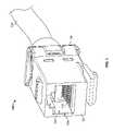
- FIG. 1is a front perspective view of an electrical connector 100 formed in accordance with an exemplary embodiment.
- the electrical connector 100is illustrated as an RJ-45 jack or receptacle, however the subject matter described herein may be used with other types of electrical connectors.
- the RJ-45 jackis thus merely illustrative.
- the electrical connector 100is provided at the end of a cable 101 .
- the cable 101includes multiple wires, arranged in differential pairs, such as in a twisted wire pair configuration.
- the electrical connector 100has a front or mating end 102 and a wire termination end 104 .
- a mating cavity 106is provided at the mating end 102 and is configured to receive a mating connector (not shown) therein.
- a mating end opening 108is also provided at the mating end 102 that provides access to the mating cavity 106 .
- Jack contacts 110are arranged within the mating cavity 106 in an array for mating engagement with mating contacts (not shown) of the mating connector.
- the mating cavity 106accepts an RJ-45 plug (not shown) inserted through the mating end opening 108 .
- the RJ-45 plughas mating contacts which electrically interface with the array of jack contacts 110 .
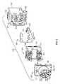
- FIG. 2is an exploded view of the electrical connector 100 illustrating a cable strain relief element 120 .
- the electrical connector 100includes a jack housing 122 , a contact sub-assembly 124 and a wire termination sub-assembly 126 .
- the contact sub-assembly 124is loaded into the jack housing 122 and the wire termination sub-assembly 126 is coupled to the jack housing 122 .
- the jack housing 122is generally box-shaped, however the jack housing 122 may have any shape depending on the particular application.
- the jack housing 122extends between the front end 102 and a rear end 128 .
- the mating cavity 106extends at least partially between the front and rear ends 102 , 128 .
- the jack housing 122is fabricated from a dielectric material, such as a plastic material.
- the jack housing 122may be shielded, such as by being fabricated by a metal material or a metalized plastic material, or by having a shield element.
- the jack housing 122includes latches 130 , 132 for mounting to a wall panel.
- the jack housing 122also includes slots 134 in side walls of the jack housing 122 .
- the contact sub-assembly 124includes a substrate 136 , such as a circuit board, and a tray 138 extending from one side of the substrate 136 .
- the jack contacts 110are mounted to the substrate 136 and are supported by the tray 138 .
- the jack contacts 110may include pins that are through-hole mounted to the substrate 136 .
- the jack contacts 110may be soldered to the substrate 136 or the jack contacts 110 may be supported by the substrate 136 for direct mating with the wires of the cables or with other contacts.
- the contact sub-assembly 124is received in the jack housing 122 such that the jack contacts 110 are presented at the mating cavity 106 .
- the wire termination sub-assembly 126includes a wire termination housing 140 that holds a plurality of wire termination contacts 142 in respective contact towers 144 .
- the contact towers 144extend from a rear end of the housing 140 and include slots 146 that receive the wires of the cable 101 (shown in FIG. 1 ).
- the contacts 142are illustrated as being insulation displacement contacts, however any type of contacts may be provided for terminating to the individual wires of the cable 101 .
- the contacts 142are configured to be electrically and mechanically coupled to the substrate 136 of the contact sub-assembly 124 when the electrical connector 100 is assembled.
- the contacts 142may include pins that project from a mating end 148 of the housing 140 and that are received in through-holes in the substrate 136 .
- traces routed along the substrate 136may connect the contacts 142 with the jack contacts 110 .
- the contacts 142may be press-fit or soldered to the through-holes in the substrate 136 .
- the wire termination sub-assembly 126is coupled to the rear end 128 of the jack housing 122 .
- the housing 140includes tabs 150 on the sides of the housing 140 that are received in the slots 134 in the jack housing 122 to secure the wire termination sub-assembly 126 to the jack housing 122 .
- the strain relief element 120is coupled to the housing 140 and is configured to hold the cable 101 (shown in FIG. 1 ) and/or the associated wires of the cable 101 .
- the strain relief element 120includes an end wall 152 that defines the wire termination end 104 of the electrical connector 100 . When the electrical connector 100 is assembled, the strain relief element 120 defines an end cap at the wire termination end 104 .
- the strain relief element 120also includes an opening 154 extending therethrough that is configured to receive the cable 101 . The opening 154 extends transversely through the end wall 152 .
- the strain relief element 120includes a boss 156 extending rearward from the end wall 152 .
- the boss 156defines a channel 158 extending therethrough.
- a plurality of flexible beams 160 and a plurality of ribs 162extend axially along, and inward into, the channel 158 from the boss 156 .
- FIG. 2illustrates four flexible beams 160 and four ribs 162 positioned between adjacent ones of the flexible beams 160 .
- Other embodimentsmay have any number of flexible beams 160 and ribs 162 , including just a single beam 160 and/or a single rib 162 .
- the strain relief element 120may not include any beams 160 .
- the channel 158extends between a distal end 164 and a proximal end 166 that is substantially aligned with the end wall 152 .
- the distal end 164is provided a distance from the proximal end 166 and/or the end wall 152 .
- the opening 154is defined at the distal end 164 of the boss 156 .
- the flexible beams 160 and ribs 162extend at least partially between the distal end 164 and the proximal end 166 .
- the flexible beams 160 and ribs 162extend from the distal end 164 to the proximal end 166 .
- the flexible beams 160 and the ribs 162cooperate to engage and/or hold the cable 101 within the strain relief element 120 .
- the flexible beams 160 and the ribs 162may reduce stresses on the wires due to bending or other movement of the cable 101 .
- FIG. 3is a perspective view of the interior side of the strain relief element 120 .
- the strain relief element 120includes the end wall 152 and top and bottom walls 170 , 172 .
- Tabs 174are provided on the top and bottom walls 170 , 172 for mounting to the housing 140 (shown in FIG. 2 ).
- a plurality of inner walls 176are provided on the interior side of the strain relief element 120 .
- the inner walls 176may be sized, shaped and positioned to complement the housing 140 of the wire termination sub-assembly 126 (shown in FIG. 2 ), such as by fitting between and/or around the contact towers 144 (shown in FIG. 2 ).
- the inner walls 176may be used to organize and/or position the wires of the cable 101 (shown in FIG. 1 ) during assembly of the strain relief element 120 with the housing 140 .
- the wiresmay be laced around and/or through the inner walls 176 such that the wires are properly positioned for mating with the contacts 142 during assembly of the strain relief element 120 with the housing 140 .
- the ribs 162are illustrated in FIG. 3 as extending along the boss 156 to the end of the channel 158 .
- the ribs 162extend axially along the boss 156 .
- rails 178are provided between the ribs 162 .
- the rails 178define a radially inner surface of the boss 156 and radially outer surface of the channel 158 .
- the rails 178are defined by the boss 156 .
- the rails 178extend from the distal end 164 to the proximal end 166 and are positioned radially outward from the flexible beams 160 . In other words, the flexible beams 160 are aligned with, and positioned radially inward with respect to, the rails 178 .
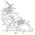
- FIG. 4is a cross-sectional view of the strain relief element 120 showing a plurality of flexible beams 160 .
- the flexible beams 160extend between fixed ends 180 and free ends 182 .
- the flexible beams 160thus define cantilevered beams that are attached to the boss 156 at the fixed ends 180 .
- the flexible beams 160are fixed proximate the opening 154 and the free ends 182 are substantially aligned with the end wall 152 .
- the free ends 182are generally elevated above the corresponding rails 178 such that a flex space 184 is defined between the flexible beams 160 and the rails 178 .
- the flexible beams 160are flexed outward and engage the cable 101 to hold the cable 101 between the flexible beams 160 .
- the flexing of the flexible beams 160provides a normal force on the cable 101 in a generally radially inward direction.
- retention features 186extend radially inward from the flexible beams 160 .
- the retention features 186are configured to engage the cable 101 when the cable 101 is loaded into the strain relief element 120 .
- the retention features 186are positioned generally centrally along the beams 160 , however, the location may be strategically selected to any location along the beam 160 .
- the location of the retention feature 186may control an amount of normal force on the cable 101 or the location of the retention feature 186 may control an amount of deflection or a rate of deflection of the beam 160 .
- the size and/or shape of the retention feature 186may control an amount of deflection or a rate of deflection of the beam 160 .
- the flexible beams 160may be integrally formed with the boss 156 and/or the strain relief element 120 .
- the strain relief element 120may be a molded plastic material.
- the strain relief element 120may be coated or plated or otherwise fabricated from a conductive material to provide shielding and the flexible beams 160 may engage a shield or cable braid of the cable 101 to provide a ground path between the cable 101 and the strain relief element 120 .
- an even number of flexible beams 160are provided and the flexible beams 160 are circumferentially spaced apart from one another around the channel 158 .
- Each flexible beam 160may have a complimentary flexible beam 160 directly opposite therefrom that together define a beam set (e.g. the flexible beams 160 shown in cross-section in FIG. 4 ).
- the flexible beams 160 of the beam setprovide opposite normal forces on the cable 101 .
- the flexible beams 160 of a beam setare separated from one another by a fixed end distance 188 between the fixed ends 180 .
- the flexible beams 160 of a beam setare separated from one another by a free end distance 190 between the free ends 182 .
- the distances 188 , 190may be the same as one another or may be different from one another.
- the fixed end distance 188is fixed and does not change upon loading or movement of the cable 101 .
- the free end distance 190is changeable as the cable 101 is loaded into the channel 158 by flexing the flexible beams 160 outward.
- FIG. 5is a cross-sectional partial view of the strain relief element 120 illustrating the flexible beam 160 in an un-deflected state (e.g. the left view in FIG. 5 ) and a deflected state (e.g. the right view in FIG. 5 ).
- the flexible beam 160may be transferred to the deflected state when the cable 101 (shown in FIG. 1 ) is loaded into the strain relief element 120 .
- the cable 101engages the flexible beam 160 and/or the retention feature 186
- the free end 182 of the flexible beam 160is pushed generally toward the rail 178 .
- the diameter of the cable 101is one factor that determines how much the flexible beam 160 deflects.
- the beam 160begins to fill the flex space 184 .
- the beam 160imparts a normal force on the cable 101 in a direction generally away from the beam 160 , such as the direction of arrow A illustrated in FIG. 5 .
- the flexible beam 160may engage the rail 178 which defines a flex limit, however, the amount of deflection may be less than the amount needed to engage the rail 178 , depending on the size of the cable 101 .
- the beam 160defines a simply supported beam as opposed to a cantilevered beam.
- the beam 160may function differently than a cantilevered beam. For example, the normal force imparted on the cable 101 may be different.
- the normal force imparted on the cable 101 by the beam 160 as a cantilevered beamis less than the normal force imparted on the cable 101 by the beam 160 as a simply supported beam.
- further deflection of the beam 160deflects the beam 160 generally at the center of the beam 160 , such as proximate to the retention feature 186 .
- FIG. 6is a rear perspective exploded view of an alternative electrical connector 200 .
- the electrical connector 200is similar to the electrical connector 100 in some respects, and like components are identified with like reference numerals.
- the electrical connector 200includes a wire termination sub-assembly 202 coupled to the jack housing 122 .
- the wire termination sub-assembly 202includes a housing 204 holding a plurality of contacts 206 .
- the housing 204includes a plurality of walls 208 defining a chamber 210 extending inward from a wire termination end 212 .
- the walls 208include a plurality of rails 214 that extend along the walls 208 . In the illustrated embodiment, four rails 214 are provided. Optionally, the rails 214 may be curved.
- the wire termination sub-assembly 202also includes a strain relief element 216 .
- the strain relief element 216includes an end wall 218 and an opening 220 extending therethrough.
- a plurality of flexible beams 222extend inward from the end wall 218 at the opening 220 .
- the flexible beams 222include fixed ends 224 and free ends 226 .
- the beams 222may be rotated radially outward about the fixed ends 224 when a cable is inserted through the opening 220 .
- the beams 222impart a normal force on the cable when inserted therethrough.
- the strain relief element 216when the strain relief element 216 is coupled to the housing 204 , the beams 222 are substantially aligned with the rails 214 .
- the beams 222may be deflected until the free ends 226 engage the rails 214 , and in some embodiments may be further deflected even after the free ends 226 engage the rails 214 , such as by deflecting the center portion of the beams 222 outward.
- FIG. 7is a cross-sectional view of the assembled electrical connector 200 .
- FIG. 7illustrates the strain relief element 216 coupled to the housing 204 .
- the flexible beams 222are aligned with the rails 214 .
- the beams 222are deflected outward toward the rails 214 , which define flex limits for the free ends 226 of the beams 222 .
- the cableis inserted into the strain relief element 216 prior to coupling the strain relief element 216 to the housing 204 .
Landscapes
- Details Of Connecting Devices For Male And Female Coupling (AREA)
Abstract
Description
Claims (18)
Priority Applications (12)
| Application Number | Priority Date | Filing Date | Title |
|---|---|---|---|
| US12/143,291US7621772B1 (en) | 2008-06-20 | 2008-06-20 | Electrical connector with a compliant cable strain relief element |
| US12/485,457US7874865B2 (en) | 2008-06-20 | 2009-06-16 | Electrical connector with a compliant cable strain relief element |
| KR1020107028390AKR101311106B1 (en) | 2008-06-20 | 2009-06-18 | Electrical connector with a compliant cable strain relief element |
| PCT/US2009/003640WO2009154759A1 (en) | 2008-06-20 | 2009-06-18 | Electrical connector with a compliant cable strain relief element |
| CN2009801230351ACN102067388B (en) | 2008-06-20 | 2009-06-18 | Electrical connector with a compliant cable strain relief element |
| EP09767072.3AEP2308138B1 (en) | 2008-06-20 | 2009-06-18 | Electrical connector with a compliant cable strain relief element |
| CA2727981ACA2727981C (en) | 2008-06-20 | 2009-06-18 | Electrical connector with a compliant cable strain relief element |
| HK11107661.0AHK1153574B (en) | 2008-06-20 | 2009-06-18 | Electrical connector with a compliant cable strain relief element |
| MX2010014046AMX2010014046A (en) | 2008-06-20 | 2009-06-18 | Electrical connector with a compliant cable strain relief element. |
| JP2011514613AJP5388242B2 (en) | 2008-06-20 | 2009-06-18 | Electrical connector with elastic cable strain relief member |
| TW098120576ATWI463746B (en) | 2008-06-20 | 2009-06-19 | Electrical connector with a compliant cable strain relief element |
| ARP090102280AAR072276A1 (en) | 2008-06-20 | 2009-06-22 | ELECTRICAL CONNECTOR WITH A FLEXIBLE VOLTAGE RELIEF ELEMENT |
Applications Claiming Priority (1)
| Application Number | Priority Date | Filing Date | Title |
|---|---|---|---|
| US12/143,291US7621772B1 (en) | 2008-06-20 | 2008-06-20 | Electrical connector with a compliant cable strain relief element |
Related Child Applications (1)
| Application Number | Title | Priority Date | Filing Date |
|---|---|---|---|
| US12/485,457Continuation-In-PartUS7874865B2 (en) | 2008-06-20 | 2009-06-16 | Electrical connector with a compliant cable strain relief element |
Publications (1)
| Publication Number | Publication Date |
|---|---|
| US7621772B1true US7621772B1 (en) | 2009-11-24 |
Family
ID=41327773
Family Applications (1)
| Application Number | Title | Priority Date | Filing Date |
|---|---|---|---|
| US12/143,291ActiveUS7621772B1 (en) | 2008-06-20 | 2008-06-20 | Electrical connector with a compliant cable strain relief element |
Country Status (1)
| Country | Link |
|---|---|
| US (1) | US7621772B1 (en) |
Cited By (16)
| Publication number | Priority date | Publication date | Assignee | Title |
|---|---|---|---|---|
| US20100285688A1 (en)* | 2008-01-02 | 2010-11-11 | Jeroen De Bruijn | Cable connector and cable clamp |
| US20150079837A1 (en)* | 2013-08-14 | 2015-03-19 | Lear Corporation | Electric Connector with Wire Retainer Tube |
| US20150311646A1 (en)* | 2014-04-23 | 2015-10-29 | Tyco Electronics Corporation | Electrical connector with shield cap and shielded terminals |
| CN105762564A (en)* | 2010-02-03 | 2016-07-13 | 泰科电子荷兰公司 | Enclosure assembly for a connector, strain relief element, and method |
| US20160268727A1 (en)* | 2013-12-26 | 2016-09-15 | Yazaki Corporation | Rear holder |
| ES2584540A1 (en)* | 2015-03-27 | 2016-09-28 | Te Connectivity Amp España, S.L.U. | Latch for telecommunications connector |
| US20160336699A1 (en)* | 2014-01-20 | 2016-11-17 | Reichle & De-Massari Ag | Plug connector device |
| US11158980B2 (en)* | 2018-11-30 | 2021-10-26 | Commscope Technologies Llc | Modular telecommunications plug and method |
| EP3793037A4 (en)* | 2018-12-28 | 2022-05-18 | Jiangsu Enman Electronic Industry Co., Ltd. | Pre-organized wire fastening device, electric plug connector adopting structure and female seat thereof |
| US11356751B2 (en) | 2017-06-19 | 2022-06-07 | Commscope Technologies Llc | High density bezel for patch panel |
| US11356752B2 (en) | 2017-11-10 | 2022-06-07 | Commscope Technologies Llc | Telecommunications panel with grounding wire |
| US11367985B2 (en)* | 2016-08-15 | 2022-06-21 | Commscope Technologies Llc | Connector assembly with grounding |
| US11509105B2 (en) | 2015-03-20 | 2022-11-22 | CommScope Connectivity Spain, S.L. | Connector with separable lacing fixture |
| US12003059B2 (en) | 2018-11-30 | 2024-06-04 | Commscope Technologies Llc | Modular telecommunications plug and method |
| US12170426B2 (en) | 2019-07-11 | 2024-12-17 | Commscope Technologies Llc | Modular telecommunications plug and method |
| US12206205B2 (en) | 2015-03-27 | 2025-01-21 | CommScope Connectivity Spain, S.L. | Cover assembly for a telecommunications connector |
Citations (24)
| Publication number | Priority date | Publication date | Assignee | Title |
|---|---|---|---|---|
| US1725883A (en)* | 1928-02-10 | 1929-08-27 | Chase Companies Inc | Connecter for attaching electric cables or conduits to outlet boxes and the like |
| US1830250A (en)* | 1929-04-02 | 1931-11-03 | Thomas B Tiefenbacher | Outlet box fitting |
| US3858151A (en)* | 1973-06-04 | 1974-12-31 | Eaton Corp | Flexible conduit connector |
| US4441776A (en)* | 1981-11-09 | 1984-04-10 | Itt Corporation | Quick detachable coupling |
| US4711507A (en)* | 1985-10-07 | 1987-12-08 | Thomas & Betts Corporation | Electrical connector and latching apparatus therefor |
| US4737118A (en)* | 1985-12-20 | 1988-04-12 | Amp Incorporated | Hermaphroditic flat cable connector |
| US5445538A (en)* | 1993-11-17 | 1995-08-29 | Thomas & Betts Corporation | Electrical connector strain relief |
| US5732984A (en)* | 1980-10-29 | 1998-03-31 | Proprietary Technology, Inc. | Manually releasable quick connector |
| US5866853A (en)* | 1993-10-07 | 1999-02-02 | Sheehan; Robert K. | Liquid-tight, strain-relief connector for connecting conduit and the like |
| US6056586A (en)* | 1998-07-30 | 2000-05-02 | Lucent Technologies Inc. | Anchoring member for a communication cable |
| US6142828A (en) | 1998-11-24 | 2000-11-07 | The Whitaker Corporation | Shielded connector having adjustable cable exit |
| US6238231B1 (en)* | 1997-09-03 | 2001-05-29 | Avaya Technology Corp. | Strain relief apparatus for use in a communication plug |
| US20010027043A1 (en)* | 2000-03-01 | 2001-10-04 | Kazuyaki Shiraki | Electrical connection system |
| US6422884B1 (en)* | 2000-06-27 | 2002-07-23 | Sentinel Lighting Wiring Systems, Inc. | Pre-wired circuit component for flexible wiring system |
| US20020155746A1 (en)* | 2001-04-19 | 2002-10-24 | Simpson Jeffrey S. | Cable assembly latch |
| US20030100215A1 (en)* | 2001-11-29 | 2003-05-29 | Werner Bachman | Durable rj-45 data connector assembly |
| US6872886B2 (en)* | 2001-05-01 | 2005-03-29 | Bridgeport Fittings, Inc. | Electrical cable connector |
| US20050202697A1 (en)* | 2004-03-12 | 2005-09-15 | Panduit Corp. | Methods and apparatus for reducing crosstalk in electrical connectors |
| US6953362B2 (en)* | 2000-08-17 | 2005-10-11 | Krone Gmbh | Electrical plug connector with cable manager |
| US20070141908A1 (en)* | 2005-05-02 | 2007-06-21 | Tyco Electronics Corporation | Electrical connector with enhanced jack interface |
| US20070240902A1 (en)* | 2004-02-25 | 2007-10-18 | Paul Tapper | Cable Entry Device Comprising Means for Adjustment |
| US20070278006A1 (en)* | 2006-06-05 | 2007-12-06 | Halex/Scott Fetzer Company | Snap-in connector for electrical junction box |
| US7384298B2 (en)* | 2005-08-08 | 2008-06-10 | Panduit Corp. | Wire containment cap |
| US7401402B2 (en)* | 2003-03-11 | 2008-07-22 | Adc Gmbh | Method for high-frequency tuning an electrical device, and a printed circuit board suitable therefor |
- 2008
- 2008-06-20USUS12/143,291patent/US7621772B1/enactiveActive
Patent Citations (27)
| Publication number | Priority date | Publication date | Assignee | Title |
|---|---|---|---|---|
| US1725883A (en)* | 1928-02-10 | 1929-08-27 | Chase Companies Inc | Connecter for attaching electric cables or conduits to outlet boxes and the like |
| US1830250A (en)* | 1929-04-02 | 1931-11-03 | Thomas B Tiefenbacher | Outlet box fitting |
| US3858151A (en)* | 1973-06-04 | 1974-12-31 | Eaton Corp | Flexible conduit connector |
| US5732984A (en)* | 1980-10-29 | 1998-03-31 | Proprietary Technology, Inc. | Manually releasable quick connector |
| US4441776A (en)* | 1981-11-09 | 1984-04-10 | Itt Corporation | Quick detachable coupling |
| US4711507A (en)* | 1985-10-07 | 1987-12-08 | Thomas & Betts Corporation | Electrical connector and latching apparatus therefor |
| US4737118A (en)* | 1985-12-20 | 1988-04-12 | Amp Incorporated | Hermaphroditic flat cable connector |
| US5866853A (en)* | 1993-10-07 | 1999-02-02 | Sheehan; Robert K. | Liquid-tight, strain-relief connector for connecting conduit and the like |
| US5445538A (en)* | 1993-11-17 | 1995-08-29 | Thomas & Betts Corporation | Electrical connector strain relief |
| US6238231B1 (en)* | 1997-09-03 | 2001-05-29 | Avaya Technology Corp. | Strain relief apparatus for use in a communication plug |
| US6056586A (en)* | 1998-07-30 | 2000-05-02 | Lucent Technologies Inc. | Anchoring member for a communication cable |
| US6142828A (en) | 1998-11-24 | 2000-11-07 | The Whitaker Corporation | Shielded connector having adjustable cable exit |
| US20010027043A1 (en)* | 2000-03-01 | 2001-10-04 | Kazuyaki Shiraki | Electrical connection system |
| US6422884B1 (en)* | 2000-06-27 | 2002-07-23 | Sentinel Lighting Wiring Systems, Inc. | Pre-wired circuit component for flexible wiring system |
| US6953362B2 (en)* | 2000-08-17 | 2005-10-11 | Krone Gmbh | Electrical plug connector with cable manager |
| US20020155746A1 (en)* | 2001-04-19 | 2002-10-24 | Simpson Jeffrey S. | Cable assembly latch |
| US6872886B2 (en)* | 2001-05-01 | 2005-03-29 | Bridgeport Fittings, Inc. | Electrical cable connector |
| US6582248B2 (en)* | 2001-11-29 | 2003-06-24 | Neutrik Ag | Durable RJ-45 data connector assembly |
| US20030100215A1 (en)* | 2001-11-29 | 2003-05-29 | Werner Bachman | Durable rj-45 data connector assembly |
| US7401402B2 (en)* | 2003-03-11 | 2008-07-22 | Adc Gmbh | Method for high-frequency tuning an electrical device, and a printed circuit board suitable therefor |
| US20070240902A1 (en)* | 2004-02-25 | 2007-10-18 | Paul Tapper | Cable Entry Device Comprising Means for Adjustment |
| US20050202697A1 (en)* | 2004-03-12 | 2005-09-15 | Panduit Corp. | Methods and apparatus for reducing crosstalk in electrical connectors |
| US20070141908A1 (en)* | 2005-05-02 | 2007-06-21 | Tyco Electronics Corporation | Electrical connector with enhanced jack interface |
| US7404739B2 (en)* | 2005-05-02 | 2008-07-29 | Tyco Electronics Corporation | Electrical connector with enhanced jack interface |
| US7384298B2 (en)* | 2005-08-08 | 2008-06-10 | Panduit Corp. | Wire containment cap |
| US20070278006A1 (en)* | 2006-06-05 | 2007-12-06 | Halex/Scott Fetzer Company | Snap-in connector for electrical junction box |
| US7432452B2 (en)* | 2006-06-05 | 2008-10-07 | Halex/Scott Fetzer Company | Snap-in connector for electrical junction box |
Cited By (30)
| Publication number | Priority date | Publication date | Assignee | Title |
|---|---|---|---|---|
| US8342877B2 (en)* | 2008-01-02 | 2013-01-01 | Fci | Cable connector and cable clamp |
| US20100285688A1 (en)* | 2008-01-02 | 2010-11-11 | Jeroen De Bruijn | Cable connector and cable clamp |
| CN105762564A (en)* | 2010-02-03 | 2016-07-13 | 泰科电子荷兰公司 | Enclosure assembly for a connector, strain relief element, and method |
| CN105762564B (en)* | 2010-02-03 | 2019-01-29 | 泰科电子连接荷兰公司 | Closed component, strain removing element and method for connector |
| US20150079837A1 (en)* | 2013-08-14 | 2015-03-19 | Lear Corporation | Electric Connector with Wire Retainer Tube |
| CN104682090A (en)* | 2013-08-14 | 2015-06-03 | 李尔公司 | Electric connector with wire retainer tube |
| CN104682090B (en)* | 2013-08-14 | 2020-02-11 | 李尔公司 | Electrical connector with wire retention tube |
| US9281611B2 (en)* | 2013-08-14 | 2016-03-08 | Lear Corporation | Electric connector with wire retainer tube |
| US20160268727A1 (en)* | 2013-12-26 | 2016-09-15 | Yazaki Corporation | Rear holder |
| US9640903B2 (en)* | 2013-12-26 | 2017-05-02 | Yazaki Corporation | Rear holder capable of absorbing dimensional variations in electric wires |
| US10122135B2 (en)* | 2014-01-20 | 2018-11-06 | Reichle & De-Massari Ag | Plug connector device having a wiring block with at least one receiving region |
| US20160336699A1 (en)* | 2014-01-20 | 2016-11-17 | Reichle & De-Massari Ag | Plug connector device |
| US10476212B2 (en) | 2014-04-23 | 2019-11-12 | Commscope Technologies Llc | Electrical connector with shield cap and shielded terminals |
| US9847607B2 (en)* | 2014-04-23 | 2017-12-19 | Commscope Technologies Llc | Electrical connector with shield cap and shielded terminals |
| US20150311646A1 (en)* | 2014-04-23 | 2015-10-29 | Tyco Electronics Corporation | Electrical connector with shield cap and shielded terminals |
| US11509105B2 (en) | 2015-03-20 | 2022-11-22 | CommScope Connectivity Spain, S.L. | Connector with separable lacing fixture |
| US12355196B2 (en) | 2015-03-27 | 2025-07-08 | CommScope Connectivity Spain, S.L. | Latch for telecommunications connector |
| US12206205B2 (en) | 2015-03-27 | 2025-01-21 | CommScope Connectivity Spain, S.L. | Cover assembly for a telecommunications connector |
| US11342718B2 (en) | 2015-03-27 | 2022-05-24 | CommScope Connectivity Spain, S.L. | Latch for telecommunications connector |
| ES2584540A1 (en)* | 2015-03-27 | 2016-09-28 | Te Connectivity Amp España, S.L.U. | Latch for telecommunications connector |
| US11367985B2 (en)* | 2016-08-15 | 2022-06-21 | Commscope Technologies Llc | Connector assembly with grounding |
| US12149032B2 (en)* | 2016-08-15 | 2024-11-19 | Commscope Technologies Llc | Connector assembly with grounding |
| US20220393412A1 (en)* | 2016-08-15 | 2022-12-08 | Commscope Technologies Llc | Connector assembly with grounding |
| US11356751B2 (en) | 2017-06-19 | 2022-06-07 | Commscope Technologies Llc | High density bezel for patch panel |
| US11838700B2 (en) | 2017-06-19 | 2023-12-05 | Commscope Technologies Llc | High density bezel for patch panel |
| US11356752B2 (en) | 2017-11-10 | 2022-06-07 | Commscope Technologies Llc | Telecommunications panel with grounding wire |
| US12003059B2 (en) | 2018-11-30 | 2024-06-04 | Commscope Technologies Llc | Modular telecommunications plug and method |
| US11158980B2 (en)* | 2018-11-30 | 2021-10-26 | Commscope Technologies Llc | Modular telecommunications plug and method |
| EP3793037A4 (en)* | 2018-12-28 | 2022-05-18 | Jiangsu Enman Electronic Industry Co., Ltd. | Pre-organized wire fastening device, electric plug connector adopting structure and female seat thereof |
| US12170426B2 (en) | 2019-07-11 | 2024-12-17 | Commscope Technologies Llc | Modular telecommunications plug and method |
Similar Documents
| Publication | Publication Date | Title |
|---|---|---|
| US7621772B1 (en) | Electrical connector with a compliant cable strain relief element | |
| CA2727981C (en) | Electrical connector with a compliant cable strain relief element | |
| US8449330B1 (en) | Cable header connector | |
| US8449329B1 (en) | Cable header connector having cable subassemblies with ground shields connected to a metal holder | |
| US7909622B2 (en) | Shielded cassette for a cable interconnect system | |
| RU2667090C2 (en) | Electrical connector with guarantied terminal position | |
| US8337238B2 (en) | Cable clip for a connector assembly | |
| JPH10321306A (en) | Connector with shield having latch and grounding structure | |
| US7878824B2 (en) | Shielded cassette for a cable interconnect system | |
| WO2017199756A1 (en) | Electrical connector equipped with signal terminals and ground terminal and electrical connector device using same electrical connector | |
| US7568949B2 (en) | Connecting socket for a data network | |
| US6945795B1 (en) | Quadrax interconnect grounding | |
| US20210273357A1 (en) | Connector assembly with interchangeable front | |
| US11462342B2 (en) | Cable harness assembly with a shielded twisted pair cable | |
| CN116404486A (en) | Cable connector assembly | |
| HK1153574B (en) | Electrical connector with a compliant cable strain relief element | |
| US20040147146A1 (en) | Receptacle connector with separable ground fingers | |
| US20230208061A1 (en) | Connector Having a Housing with a Window | |
| CN118825724A (en) | Connector having a dielectric fixed in a housing |
Legal Events
| Date | Code | Title | Description |
|---|---|---|---|
| AS | Assignment | Owner name:TYCO ELECTRONICS CORPORATION, PENNSYLVANIA Free format text:ASSIGNMENT OF ASSIGNORS INTEREST;ASSIGNOR:TOBEY, SHAWN PHILLIP;REEL/FRAME:021129/0492 Effective date:20080620 | |
| STCF | Information on status: patent grant | Free format text:PATENTED CASE | |
| FPAY | Fee payment | Year of fee payment:4 | |
| AS | Assignment | Owner name:TYCO ELECTRONICS SERVICES GMBH, SWITZERLAND Free format text:ASSIGNMENT OF ASSIGNORS INTEREST;ASSIGNOR:TYCO ELECTRONICS CORPORATION;REEL/FRAME:036074/0740 Effective date:20150410 | |
| AS | Assignment | Owner name:COMMSCOPE EMEA LIMITED, IRELAND Free format text:ASSIGNMENT OF ASSIGNORS INTEREST;ASSIGNOR:TYCO ELECTRONICS SERVICES GMBH;REEL/FRAME:036956/0001 Effective date:20150828 | |
| AS | Assignment | Owner name:COMMSCOPE TECHNOLOGIES LLC, NORTH CAROLINA Free format text:ASSIGNMENT OF ASSIGNORS INTEREST;ASSIGNOR:COMMSCOPE EMEA LIMITED;REEL/FRAME:037012/0001 Effective date:20150828 | |
| AS | Assignment | Owner name:JPMORGAN CHASE BANK, N.A., AS COLLATERAL AGENT, ILLINOIS Free format text:PATENT SECURITY AGREEMENT (TERM);ASSIGNOR:COMMSCOPE TECHNOLOGIES LLC;REEL/FRAME:037513/0709 Effective date:20151220 Owner name:JPMORGAN CHASE BANK, N.A., AS COLLATERAL AGENT, ILLINOIS Free format text:PATENT SECURITY AGREEMENT (ABL);ASSIGNOR:COMMSCOPE TECHNOLOGIES LLC;REEL/FRAME:037514/0196 Effective date:20151220 Owner name:JPMORGAN CHASE BANK, N.A., AS COLLATERAL AGENT, IL Free format text:PATENT SECURITY AGREEMENT (TERM);ASSIGNOR:COMMSCOPE TECHNOLOGIES LLC;REEL/FRAME:037513/0709 Effective date:20151220 Owner name:JPMORGAN CHASE BANK, N.A., AS COLLATERAL AGENT, IL Free format text:PATENT SECURITY AGREEMENT (ABL);ASSIGNOR:COMMSCOPE TECHNOLOGIES LLC;REEL/FRAME:037514/0196 Effective date:20151220 | |
| FPAY | Fee payment | Year of fee payment:8 | |
| AS | Assignment | Owner name:COMMSCOPE, INC. OF NORTH CAROLINA, NORTH CAROLINA Free format text:RELEASE BY SECURED PARTY;ASSIGNOR:JPMORGAN CHASE BANK, N.A.;REEL/FRAME:048840/0001 Effective date:20190404 Owner name:ANDREW LLC, NORTH CAROLINA Free format text:RELEASE BY SECURED PARTY;ASSIGNOR:JPMORGAN CHASE BANK, N.A.;REEL/FRAME:048840/0001 Effective date:20190404 Owner name:COMMSCOPE TECHNOLOGIES LLC, NORTH CAROLINA Free format text:RELEASE BY SECURED PARTY;ASSIGNOR:JPMORGAN CHASE BANK, N.A.;REEL/FRAME:048840/0001 Effective date:20190404 Owner name:ALLEN TELECOM LLC, ILLINOIS Free format text:RELEASE BY SECURED PARTY;ASSIGNOR:JPMORGAN CHASE BANK, N.A.;REEL/FRAME:048840/0001 Effective date:20190404 Owner name:REDWOOD SYSTEMS, INC., NORTH CAROLINA Free format text:RELEASE BY SECURED PARTY;ASSIGNOR:JPMORGAN CHASE BANK, N.A.;REEL/FRAME:048840/0001 Effective date:20190404 Owner name:COMMSCOPE, INC. OF NORTH CAROLINA, NORTH CAROLINA Free format text:RELEASE BY SECURED PARTY;ASSIGNOR:JPMORGAN CHASE BANK, N.A.;REEL/FRAME:049260/0001 Effective date:20190404 Owner name:REDWOOD SYSTEMS, INC., NORTH CAROLINA Free format text:RELEASE BY SECURED PARTY;ASSIGNOR:JPMORGAN CHASE BANK, N.A.;REEL/FRAME:049260/0001 Effective date:20190404 Owner name:ANDREW LLC, NORTH CAROLINA Free format text:RELEASE BY SECURED PARTY;ASSIGNOR:JPMORGAN CHASE BANK, N.A.;REEL/FRAME:049260/0001 Effective date:20190404 Owner name:COMMSCOPE TECHNOLOGIES LLC, NORTH CAROLINA Free format text:RELEASE BY SECURED PARTY;ASSIGNOR:JPMORGAN CHASE BANK, N.A.;REEL/FRAME:049260/0001 Effective date:20190404 Owner name:ALLEN TELECOM LLC, ILLINOIS Free format text:RELEASE BY SECURED PARTY;ASSIGNOR:JPMORGAN CHASE BANK, N.A.;REEL/FRAME:049260/0001 Effective date:20190404 | |
| AS | Assignment | Owner name:JPMORGAN CHASE BANK, N.A., NEW YORK Free format text:TERM LOAN SECURITY AGREEMENT;ASSIGNORS:COMMSCOPE, INC. OF NORTH CAROLINA;COMMSCOPE TECHNOLOGIES LLC;ARRIS ENTERPRISES LLC;AND OTHERS;REEL/FRAME:049905/0504 Effective date:20190404 Owner name:JPMORGAN CHASE BANK, N.A., NEW YORK Free format text:ABL SECURITY AGREEMENT;ASSIGNORS:COMMSCOPE, INC. OF NORTH CAROLINA;COMMSCOPE TECHNOLOGIES LLC;ARRIS ENTERPRISES LLC;AND OTHERS;REEL/FRAME:049892/0396 Effective date:20190404 Owner name:WILMINGTON TRUST, NATIONAL ASSOCIATION, AS COLLATE Free format text:PATENT SECURITY AGREEMENT;ASSIGNOR:COMMSCOPE TECHNOLOGIES LLC;REEL/FRAME:049892/0051 Effective date:20190404 Owner name:WILMINGTON TRUST, NATIONAL ASSOCIATION, AS COLLATERAL AGENT, CONNECTICUT Free format text:PATENT SECURITY AGREEMENT;ASSIGNOR:COMMSCOPE TECHNOLOGIES LLC;REEL/FRAME:049892/0051 Effective date:20190404 | |
| MAFP | Maintenance fee payment | Free format text:PAYMENT OF MAINTENANCE FEE, 12TH YEAR, LARGE ENTITY (ORIGINAL EVENT CODE: M1553); ENTITY STATUS OF PATENT OWNER: LARGE ENTITY Year of fee payment:12 | |
| AS | Assignment | Owner name:WILMINGTON TRUST, DELAWARE Free format text:SECURITY INTEREST;ASSIGNORS:ARRIS SOLUTIONS, INC.;ARRIS ENTERPRISES LLC;COMMSCOPE TECHNOLOGIES LLC;AND OTHERS;REEL/FRAME:060752/0001 Effective date:20211115 | |
| AS | Assignment | Owner name:APOLLO ADMINISTRATIVE AGENCY LLC, NEW YORK Free format text:SECURITY INTEREST;ASSIGNORS:ARRIS ENTERPRISES LLC;COMMSCOPE TECHNOLOGIES LLC;COMMSCOPE INC., OF NORTH CAROLINA;AND OTHERS;REEL/FRAME:069889/0114 Effective date:20241217 | |
| AS | Assignment | Owner name:RUCKUS WIRELESS, LLC (F/K/A RUCKUS WIRELESS, INC.), NORTH CAROLINA Free format text:RELEASE OF SECURITY INTEREST AT REEL/FRAME 049905/0504;ASSIGNOR:JPMORGAN CHASE BANK, N.A., AS COLLATERAL AGENT;REEL/FRAME:071477/0255 Effective date:20241217 Owner name:COMMSCOPE TECHNOLOGIES LLC, NORTH CAROLINA Free format text:RELEASE OF SECURITY INTEREST AT REEL/FRAME 049905/0504;ASSIGNOR:JPMORGAN CHASE BANK, N.A., AS COLLATERAL AGENT;REEL/FRAME:071477/0255 Effective date:20241217 Owner name:COMMSCOPE, INC. OF NORTH CAROLINA, NORTH CAROLINA Free format text:RELEASE OF SECURITY INTEREST AT REEL/FRAME 049905/0504;ASSIGNOR:JPMORGAN CHASE BANK, N.A., AS COLLATERAL AGENT;REEL/FRAME:071477/0255 Effective date:20241217 Owner name:ARRIS SOLUTIONS, INC., NORTH CAROLINA Free format text:RELEASE OF SECURITY INTEREST AT REEL/FRAME 049905/0504;ASSIGNOR:JPMORGAN CHASE BANK, N.A., AS COLLATERAL AGENT;REEL/FRAME:071477/0255 Effective date:20241217 Owner name:ARRIS TECHNOLOGY, INC., NORTH CAROLINA Free format text:RELEASE OF SECURITY INTEREST AT REEL/FRAME 049905/0504;ASSIGNOR:JPMORGAN CHASE BANK, N.A., AS COLLATERAL AGENT;REEL/FRAME:071477/0255 Effective date:20241217 Owner name:ARRIS ENTERPRISES LLC (F/K/A ARRIS ENTERPRISES, INC.), NORTH CAROLINA Free format text:RELEASE OF SECURITY INTEREST AT REEL/FRAME 049905/0504;ASSIGNOR:JPMORGAN CHASE BANK, N.A., AS COLLATERAL AGENT;REEL/FRAME:071477/0255 Effective date:20241217 |