US7620480B2 - Cooling components across a continuum - Google Patents
Cooling components across a continuumDownload PDFInfo
- Publication number
- US7620480B2 US7620480B2US11/264,786US26478605AUS7620480B2US 7620480 B2US7620480 B2US 7620480B2US 26478605 AUS26478605 AUS 26478605AUS 7620480 B2US7620480 B2US 7620480B2
- Authority
- US
- United States
- Prior art keywords
- continuum
- irreversibility
- levels
- control scheme
- policy
- Prior art date
- Legal status (The legal status is an assumption and is not a legal conclusion. Google has not performed a legal analysis and makes no representation as to the accuracy of the status listed.)
- Expired - Fee Related, expires
Links
Images


Classifications
- G—PHYSICS
- G06—COMPUTING OR CALCULATING; COUNTING
- G06F—ELECTRIC DIGITAL DATA PROCESSING
- G06F1/00—Details not covered by groups G06F3/00 - G06F13/00 and G06F21/00
- G06F1/16—Constructional details or arrangements
- G06F1/20—Cooling means
- G06F1/206—Cooling means comprising thermal management
- Y—GENERAL TAGGING OF NEW TECHNOLOGICAL DEVELOPMENTS; GENERAL TAGGING OF CROSS-SECTIONAL TECHNOLOGIES SPANNING OVER SEVERAL SECTIONS OF THE IPC; TECHNICAL SUBJECTS COVERED BY FORMER USPC CROSS-REFERENCE ART COLLECTIONS [XRACs] AND DIGESTS
- Y02—TECHNOLOGIES OR APPLICATIONS FOR MITIGATION OR ADAPTATION AGAINST CLIMATE CHANGE
- Y02D—CLIMATE CHANGE MITIGATION TECHNOLOGIES IN INFORMATION AND COMMUNICATION TECHNOLOGIES [ICT], I.E. INFORMATION AND COMMUNICATION TECHNOLOGIES AIMING AT THE REDUCTION OF THEIR OWN ENERGY USE
- Y02D10/00—Energy efficient computing, e.g. low power processors, power management or thermal management
Definitions
- a data centermay be defined as a location, for instance, a room that houses computer systems arranged in a number of racks.
- a standard rackfor instance, an electronics cabinet, is defined as an Electronics Industry Association (EIA) enclosure, 78 in. (2 meters) wide, 24 in. (0.61 meter) wide and 30 in. (0.76 meter) deep.
- EIAElectronics Industry Association
- These racksare configured to house a number of computer systems, about forty (40) systems, with future configurations of racks being designed to accommodate 200 or more systems.
- the computer systemstypically dissipate relatively significant amounts of heat during the operation of the respective components. For example, a typical computer system comprising multiple microprocessors may dissipate approximately 250 W of power. Thus, a rack containing forty (40) computer systems of this type may dissipate approximately 10 KW of power.
- a method of cooling components across a continuum having a plurality of levelsis disclosed.
- detected data related to the components across the continuumis received and evaluated.
- a control schemeis developed based upon the evaluated data, where the control scheme is configured to manipulate one or more actuators across a plurality of levels.
- the actuators across the plurality of levelsare manipulated in accordance with the developed control scheme.
- FIG. 1Ashows a block diagram of a cooling control system according to an embodiment of the invention
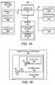
- FIG. 1Bshows a block diagram of a computational continuum, according to an embodiment of the invention
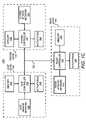
- FIG. 1Cshows a block diagram of a cooling control system according to another embodiment of the invention.
- FIG. 2shows a flow diagram of a method for cooling components across a continuum, according to an embodiment of the invention.
- FIG. 3illustrates a computer system, which may be employed to perform the various functions of the cooling control systems, according to an embodiment of the invention.
- a holistic approach to cooling components in a roomis disclosed herein. More particularly, the disclosed method for cooling the components crosses multiple levels of a continuum to achieve one or more policies.
- one or more control schemesmay be developed based upon evaluated data indicating that one or more policies are not being met.
- the one or more control schemesmay be implemented across the continuum.
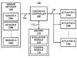
- the cooling control system 100is configured to control cooling at multiple component levels in a holistic manner.
- the multiple component levelsmay be considered as a continuum 120 (shown in FIG. 1B ) for purposes of control because the cooling control system 100 is configured to control actuators associated with each of the multiple levels under a holistic control scheme.
- the cooling control system 100may be operated in various manners to substantially increase the compaction and density of components in a room.
- the cooling control system 100may implement one or more algorithms designed to reduce or minimize the amount of energy consumed in cooling the components at a plurality of the multiple levels.
- the multiple levels in a computational environmentmay include, for instance, a chip level, a system level, a rack level, a row level, a zonal level, a room level, etc.
- FIG. 1Bonly a chip level 122 , a system level 124 , and a room level 126 are shown for purposes of simplicity of illustration. It should, however, be understood that the computational continuum 120 shown in FIG. 1B may include any number of levels as described above.
- the arrows 128generally signify that information and policy assignments may be transferred among the different levels 122 - 126 .
- the cooling control system 100includes a continuum controller 102 configured to perform evaluation and control operations in the cooling control system 100 .
- the continuum controller 102is depicted as comprising a single device, the evaluation and control operations performed by the continuum controller 102 may be performed by any number of different devices without departing from a scope of the cooling control system 100 .
- the continuum controller 102may comprise a microprocessor, a micro-controller, an application specific integrated circuit (ASIC), and the like, configured to perform the various evaluation and control operations described herein.
- ASICapplication specific integrated circuit
- At least one of the sensors 106 a - 106 nmay be positioned to detect a condition around a heat generating component, such as, a processor, a micro-controller, a high-speed video card, a memory, a semi-conductor device, and the like.
- a condition around a heat generating componentsuch as, a processor, a micro-controller, a high-speed video card, a memory, a semi-conductor device, and the like.
- another of the sensors 106 a - 106 nmay be positioned to detect a condition around a heat generating system, such as, a server, a hard drive, a monitor, and the like.
- another of the sensors 106 a - 106 nmay be positioned to detect a condition at a location in the room housing the components of the continuum 120 .
- the data pertaining to the conditions detected by the sensors 106 a - 106 nmay be transmitted to the continuum controller 102 through a network represented by the arrow 108 .
- the network 108generally represents a wired or wireless structure in the computing environment for the transmission of data between the various components of the cooling control system 100 .
- the network 108may comprise an existing network infrastructure or it may comprise a separate network configuration installed for the purpose of controlling cooling by the continuum controller 102 .
- the sensors 106 a - 106 n and/or the continuum controller 102may be equipped with or have access to software and/or hardware to enable these devices to transmit and/or receive data over the network 108 .
- the continuum controller 102may store the data received from the sensors 106 a - 106 n in a memory 110 .
- the continuum controller 102may be in communication with the memory 110 through, for instance, a memory bus represented by the arrow 112 .
- the memory 110may form part of the continuum controller 102 .
- the memory 110may be configured to provide storage of software, algorithms, and the like, that provide the functionality of the continuum controller 102 .
- the memory 110may store an operating system, application programs, program data, and the like.
- the memory 110may be implemented as a combination of volatile and non-volatile memory, such as DRAM, EEPROM, MRAM, flash memory, and the like.
- the memory 110may comprise a device configured to read from and write to a removable media, such as, a floppy disk, a CD-ROM, a DVD-ROM, or other optical or magnetic media.
- the memory 110may also store an evaluation module 114 and a control module 116 , which the continuum controller 102 may implement to control cooling provisioning in the continuum 120 .
- the evaluation module 114may comprise one or more algorithms that the continuum controller 102 may implement in evaluating the data received from the sensors 106 a - 106 n .
- the evaluation module 114may be implemented to evaluate the data to determine how one or more actuators 118 a - 118 n , where “n” is an integer greater than one, that affect cooling provisioning may be operated to meet one or more policies.
- suitable policiesinclude, for instance, thermal management based polices, energy efficiency based policies, irreversibility based policies, and performance based policies.
- Thermal management based policiesare generally designed to ensure that proper temperatures are maintained at maximum performance levels.
- Energy efficiency based policiesare designed to substantially optimize energy efficiencies of the devices contained in the computing environment.
- Irreversibility based policiesare designed to reduce the thermodynamic irreversibility of the devices by substantially optimizing flow work, thermodynamic work, and heat transfer.
- the continuum controller 102may implement the control module 116 to develop control schemes for operating the actuators 118 a - 118 n across the continuum 120 to achieve or meet one or more of the policies.
- the control schemesmay further be developed according to various policies, such as, operational policies and sustainability policies.
- Operational policiesmay be employed to govern the operation of the computational and environmental resources in the continuum 120 at, for instance, the chip, system, and room levels 122 - 126 .
- operational policiesmay prescribe required computational performance, prevent or mitigate failures in the cooling control system, provide thermal management, meet a wide variety of potential user needs, etc.
- operational policiesmay enable the selection to increase the reaction time to air conditioning failures by having redundancy or lower temperature at the expense of greater energy use.
- the policiesmay be weighted according to user needs and priorities and may be dynamic.
- the policiesmay target elements in the continuum 120 , such as, individual chips, servers, racks, etc., or the policies may target the continuum 120 as a whole.
- the computational performance policiesmay have more weight at night at the expense of operational cost policies when the cost of electricity is relatively low. Conversely, in the daytime, as the cost of electricity rises, performance policies may have less weight.
- the weightingsmay change with changes in user priorities.
- the sensors 106 a - 106 n and the actuators 118 a - 118 n associated with one or more chipsmay be configured as disclosed in commonly assigned U.S. Pat. No. 6,612,120, entitled “Spray Cooling with Local Control of Nozzles”, the disclosure of which is hereby incorporated by reference in its entirety.
- the sensors 106 a - 106 n and the actuators 118 a - 118 n associated with one or more chipsmay be configured as disclosed in commonly assigned U.S. Pat. No. 6,904,968, entitled “Method and Apparatus for Individually Cooling Components of Electronic Systems”, the disclosure of which is hereby incorporated by reference in its entirety.
- the sensors 106 a - 106 nmay comprise temperature sensors positioned at various locations in a server.
- the actuators 118 a - 118 nmay comprise one or more fans positioned to direct airflow through the server as disclosed in commonly assigned U.S. patent application Ser. No. 10/734,174, Application Publication No. 2005/0128710, entitled “Cooling System for Electronic Components”, the disclosure of which is hereby incorporated by reference in its entirety.
- the sensors 106 a - 106 n and the actuators 118 a - 118 nmay comprise refrigerated cooling components as disclosed in commonly assigned U.S. Pat. No. 7,024,573, entitled “Method and Apparatus for Cooling Heat Generating Components”, the disclosure of which is hereby incorporated by reference in its entirety.
- the sensors 106 a - 106 n and the actuators 118 a - 118 nmay be configured and operated as disclosed in commonly assigned U.S. Pat. No. 6,574,104, entitled “Smart Cooling of Data Centers”, the disclosure of which is hereby incorporated by reference in its entirety.
- the actuators 118 a - 118 nmay comprise one or both of air conditioning units and controllable vent tiles.
- the sensors 106 a - 106 n and the actuators 118 a - 118 nmay be configured and operated as disclosed in commonly assigned U.S. patent application Ser No. 10/853,529, Application Publication No. 2005/0278070, entitled “Energy Efficient CRAC Unit Operation”, the disclosure of which is hereby incorporated by reference in its entirety.
- the cooling control system 100 ′does not include the continuum controller 102 depicted in FIG. 1A . Instead, the cooling control system 100 ′ is depicted with each of the multiple levels 122 - 126 of the continuum 120 being in communication with each other. Thus, as described in greater detail herein below, in contrast to the cooling control system 100 depicted in FIG. 1A , information and policies may be transmitted to each other instead of having a centralized controller, such as the continuum controller 102 .
- any reasonably suitable number of the multiple levels 122 - 126may be included in the cooling control system 100 ′ without departing from a scope of the cooling control system 100 ′.
- single ones of the multiple levels 122 - 126have been depicted for purposes of simplicity and not of limitation.
- levels other than those depicted in FIG. 1Cmay be included in the cooling control system 100 ′ without departing from a scope of the cooling control system 100 ′. These levels may include, for instance, a rack level, a row of racks level, a cluster of racks level, etc.
- the controller 152 , 162 , 172may communicate information pertaining to conditions detected by the sensor network 104 to each other.
- the sensor network 104is depicted as being configured to detect one or more conditions at the respective levels 122 - 126 .
- the chip level 122includes a chip sensor network 154 that may comprise one or more of the sensors 106 a - 106 n depicted in FIG. 1A .
- the system level 124includes a system sensor network 164 that may also include one or more of the sensors 106 a - 106 n and the room level 126 includes a room sensor network 174 that may further include one or more of the sensors 106 a - 106 n .
- one or more of the sensors 106 a - 106 nmay form part of more than one of the levels 122 - 126 .
- the conditions detected by one or more of the sensors 106 a - 106 nmay be used to evaluate conditions at more than one level 122 - 126 .
- Each of the levels 122 - 126may also include respective memories 156 , 166 , 176 configured to provide storage of software, algorithms, and the like, that provide the functionalities of the controllers 152 , 162 , 172 .
- the memories 156 , 166 , 176may store operating systems, application programs, program data, and the like.
- the memories 156 , 166 , 176may each be implemented as a combination of volatile and non-volatile memory, such as DRAM, EEPROM, MRAM, flash memory, and the like.
- the memories 156 , 166 , 176may each comprise a device configured to read from and write to a removable media, such as, a floppy disk, a CD-ROM, a DVD-ROM, or other optical or magnetic media.
- the memories 156 , 166 , 176may each store algorithms designed to enable the controllers 152 , 162 , 172 to control respective actuators 158 , 168 , 178 , which may include one or more of the actuators 118 a - 118 n depicted in FIG. 1A .
- the memories 156 , 166 , 176may each store one or more algorithms designed to enable the cooling control system 100 ′ to be operated in a holistic manner.
- the controllers 152 , 162 , 172may collectively perform various operations of the continuum controller 102 described above.
- the controllers 152 , 162 , 172may be configured to implement an evaluation module 114 and a control module 116 .
- the controllers 152 , 162 , 172are configured to control their respective actuators 158 , 168 , 178 , based upon data pertaining to a plurality of levels in the continuum 120 and thus implement a holistic control scheme.
- a description of a manner in which the controllers 152 , 162 , 172 operateis set forth below with respect to FIG. 2 .
- FIG. 2there is shown a flow diagram of a method 200 for cooling electronic components across a continuum 120 , according to an example. It is to be understood that the following description of the method 200 is but one manner of a variety of different manners in which an example of the invention may be practiced. It should also be apparent to those of ordinary skill in the art that the method 200 represents a generalized illustration and that other steps may be added or existing steps may be removed, modified or rearranged without departing from a scope of the method 200 .
- the continuum 120is comprised of multiple levels that may include, for instance, a chip level 122 , a system level 124 , a rack level, a row level, a zonal level, a room level 126 , etc.
- the method 200may be implemented by the continuum controller 102 or the controllers 152 , 162 , 172 to evaluate data across the continuum 120 . More particularly, the continuum controller 102 or the controllers 152 , 162 , 172 may evaluate the data to develop one or more control schemes for controlling one or more actuators 118 a - 118 n across the continuum 120 .
- the continuum controller 102 or the controllers 152 , 162 , 172may control the one or more actuators 118 a - 118 n based upon polices that extend beyond any individual level of the continuum 120 .
- the method 200may be performed to substantially increase the compaction and density of computer components in a room.
- the method 200may be implemented to substantially reduce or minimize the amount of energy consumed in cooling the components in the multiple levels of the continuum 120 .
- the method 200may be initiated at step 202 in response to any of a number of stimuli or conditions.
- the method 200may be initiated with activation of the components in the room 100 , such as, air conditioning units, heat generating components, etc.
- the method 200may be manually initiated or the continuum controller 102 or the controllers 152 , 162 , 172 may be programmed to initiate the method 200 at various times, for a set duration of time, substantially continuously, etc.
- the sensors 106 a - 106 nmay detect one or more conditions and data pertaining to the detected one or more conditions may be received by the continuum controller 102 , as indicated at step 204 .
- conditions detected by the sensors 106 a - 106 n of the sensor networks 154 , 164 , 174may be communicated to each of the controllers 152 , 162 , 172 at step 204 .
- the continuum controller 102 or the controllers 152 , 162 , 172may implement an evaluation module 114 to evaluate the received data as indicated at step 206 .
- the continuum controller 102 or controllers 152 , 162 , 172may evaluate the received data to determine whether one or more policies are being met, as indicated at step 208 . If the policies are being met, the continuum controller 102 or controllers 152 , 162 , 172 may continue to receive and evaluate data as indicated at steps 204 and 206 .
- a control scheme that crosses multiple levels of the continuum 120may be developed to vary conditions in the computing environment, as indicated at step 210 . More particularly, a control scheme configured to control one or more actuators 118 a - 18 n across the continuum 120 to achieve one or more of the desired policies may be developed at step 210 .
- One of the policies that may be achievedincludes thermal management based policies, which are designed to substantially ensure that the heat generating components, such as, servers, computers, disk drives, etc., operate under proper temperature conditions at various performance levels.
- the provisioning of cooling resources at the multiple levelsmay be varied to substantially maintain temperatures at desired levels.
- a control schememay be developed at step 210 to manipulate one or more of the actuators 118 a - 118 n to substantially ensure that the heat generating components are operating under desired conditions.
- Another of the policiesmay include energy efficiency based policies, which are designed to substantially optimize energy efficiencies of cooling devices, such as, air conditioning units, condensers, fans, etc., contained in the computing environment.
- the energy efficiency levels of the devicesmay be determined according to their respective coefficients of performance and a control scheme may be developed at step 210 to manipulate one or more of the actuators 118 a - 118 n to substantially ensure that coefficients of performance of the cooling devices are at desired levels.
- a usermay select the energy efficiency needed or desired and the actuators 118 a - 118 n at the multiple levels may be operated accordingly.
- the power on chip and systemmay be changed by using a power management system to obtain the desired or needed level of energy efficiency.
- Another of the policiesmay include irreversibility based policies, which are designed to substantially minimize the overall irreversibility at the multiple levels of the continuum 120 .
- Irreversibilityrepresents irreversible processes, such as, mixing of hot and cold streams of air. By drawing finite volumes, and using temperatures at various boundaries, the level of irreversibility may be determined, for instance, the difference in temperature between the inlet of a given system and the inlet of a heat generating device, the inlet of a heat generating device to vent tile supply, etc.
- a control scheme for the actuators 118 a - 118 nmay be developed at step 210 to reduce the thermodynamic irreversibility of the system(s) by optimization of flow work, thermodynamic work and heat transfer.
- Flow workdistributes air judiciously around the room, thermodynamic work compresses the refrigerant to exchange heat at low temperature to high temperature and efficient heat transfer ensures that irreversibilities in the heat exchangers are relatively low.
- Irreversibilities in flowmay occur due to mixing of hot and cold air streams or due to flow expansion and contraction through vents/inlets and across aisles, ceiling space, plenum, etc.
- Irreversibilities in thermodynamic workmay occur due to low isentropic efficiency of the compressor or high friction losses in the cooling cycle.
- Irreversibilities in heat transfermay occur due to un-optimized heat exchanger design and operation.
- Irreversibilities in heat transfer ( ⁇ T )may also be reduced by operating the components in the continuum 120 relatively close to the heat rejection temperature or the ambient temperature.
- mis the mass flow rate
- Ris a gas constant
- Cpis the specific heat capacity of air
- T outis the outlet temperature
- T inis the inlet temperature
- P outis the outlet pressure
- P inis the inlet pressure
- T 0is a reference temperature, and in some cases, the lowest temperature of heat rejection.
- irreversibilityis a path variable
- total irreversibilityis a summation of all the combined values for every significant process in the computing environment of the continuum 120 . Processes may be identified based on control volumes created around each key region of transport. A typical process may include, for instance, heat addition in a server or flow of cold air from a vent tile to an inlet of a heat generating device.
- Another policymay be performance based, in which, manipulations of the actuators are calculated to substantially improve compute performance at the multiple levels of the continuum 120 .
- Sustainability policiesmay be employed to affect the operational cost of the cooling control system 100 , 100 ′ or reduce the effect of the computing resources on the environment in which the computing resources are contained by substantially improving operational efficiency.
- sustainability policiesmay enable the operation of cooling systems at higher temperatures to save energy at the expense of lower reaction time.
- the policiesmay also be weighted according to user needs and priorities and may be dynamic.
- the policiesmay further target elements in the computing environment, such as, individual chips, servers, racks, etc., or the policies may target the computing environment as a whole.
- the computational performance policiesmay have more weight at night at the expense of operational cost policies when the cost of electricity is relatively low. Conversely, in the daytime, as the cost of electricity rises, performance policies may have less weight.
- the weightingsmay change with changes in user priorities.
- Policiesmay further be defined to govern the placement of computational workload within the continuum 120 or within computing environments located across the globe as described above.
- step 214it may be determined as to whether the method 200 is to continue. If a “no” condition is reached at step 214 , the method 200 may end as indicated at step 216 . The method 200 may end, for instance, following a predetermined length of time, following a predetermined number of iterations, manually discontinued, etc. If a “yes” condition is reached at step 214 , the method 200 may continue beginning at step 204 . As such, the method 200 may be repeated for a number of times to substantially continuously vary the conditions based upon information shared among the continuum 120 .
- the operations illustrated in the method 200may be contained as a utility, program, or a subprogram, in any desired computer accessible medium.
- the method 200may be embodied by a computer program, which can exist in a variety of forms both active and inactive. For example, they can exist as software program(s) comprised of program instructions in source code, object code, executable code or other formats. Any of the above can be embodied on a computer readable medium, which include storage devices and signals, in compressed or uncompressed form.
- Exemplary computer readable storage devicesinclude conventional computer system RAM, ROM, EPROM, EEPROM, and magnetic or optical disks or tapes.
- Exemplary computer readable signalsare signals that a computer system hosting or running the computer program can be configured to access, including signals downloaded through the Internet or other networks. Concrete examples of the foregoing include distribution of the programs on a CD ROM or via Internet download. In a sense, the Internet itself, as an abstract entity, is a computer readable medium. The same is true of computer networks in general. It is therefore to be understood that any electronic device capable of executing the above-described functions may perform those functions enumerated above.
- FIG. 3illustrates a computer system 300 , which may be employed to perform the various functions of the continuum controller 102 or the controllers 152 , 162 , 172 described herein above, according to an embodiment.
- the computer system 300may be used as a platform for executing one or more of the functions described hereinabove with respect to the continuum controller 102 or the controllers 152 , 162 , 172 .
- the computer system 300includes one or more controllers, such as a processor 302 .
- the processor 302may be used to execute some or all of the steps described in the method 200 . Commands and data from the processor 302 are communicated over a communication bus 304 .
- the computer system 300also includes a main memory 306 , such as a random access memory (RAM), where the program code for, for instance, the continuum controller 102 or the controllers 152 , 162 , 172 , may be executed during runtime, and a secondary memory 308 .
- RAMrandom access memory
- the secondary memory 308includes, for example, one or more hard disk drives 310 and/or a removable storage drive 312 , representing a floppy diskette drive, a magnetic tape drive, a compact disk drive, etc., where a copy of the program code for the environmental control system may be stored.
- the removable storage drive 310reads from and/or writes to a removable storage unit 314 in a well-known manner.
- User input and output devicesmay include a keyboard 316 , a mouse 318 , and a display 320 .
- a display adaptor 322may interface with the communication bus 304 and the display 320 and may receive display data from the processor 302 and convert the display data into display commands for the display 320 .
- the processor 302may communicate over a network, for instance, the Internet, LAN, etc., through a network adaptor 324 .
- the computer system 300may include a system board or blade used in a rack in a data center, a conventional “white box” server or computing device, etc. Also, one or more of the components in FIG. 3 may be optional (for instance, user input devices, secondary memory, etc.).
Landscapes
- Engineering & Computer Science (AREA)
- Theoretical Computer Science (AREA)
- Human Computer Interaction (AREA)
- Physics & Mathematics (AREA)
- General Engineering & Computer Science (AREA)
- General Physics & Mathematics (AREA)
- Cooling Or The Like Of Electrical Apparatus (AREA)
- Air Conditioning Control Device (AREA)
- Control Of Heat Treatment Processes (AREA)
- Turbine Rotor Nozzle Sealing (AREA)
Abstract
Description
Σφ=φf+φwφT. Equation (1)
Claims (12)
Priority Applications (4)
| Application Number | Priority Date | Filing Date | Title |
|---|---|---|---|
| US11/264,786US7620480B2 (en) | 2005-11-01 | 2005-11-01 | Cooling components across a continuum |
| CN2006800501865ACN101356485B (en) | 2005-11-01 | 2006-11-01 | Cooling components across a continuum |
| PCT/US2006/042927WO2007053766A2 (en) | 2005-11-01 | 2006-11-01 | Cooling components across a continuum |
| EP06836867AEP1943579A2 (en) | 2005-11-01 | 2006-11-01 | Cooling components across a continuum |
Applications Claiming Priority (1)
| Application Number | Priority Date | Filing Date | Title |
|---|---|---|---|
| US11/264,786US7620480B2 (en) | 2005-11-01 | 2005-11-01 | Cooling components across a continuum |
Publications (2)
| Publication Number | Publication Date |
|---|---|
| US20070100494A1 US20070100494A1 (en) | 2007-05-03 |
| US7620480B2true US7620480B2 (en) | 2009-11-17 |
Family
ID=37769361
Family Applications (1)
| Application Number | Title | Priority Date | Filing Date |
|---|---|---|---|
| US11/264,786Expired - Fee RelatedUS7620480B2 (en) | 2005-11-01 | 2005-11-01 | Cooling components across a continuum |
Country Status (4)
| Country | Link |
|---|---|
| US (1) | US7620480B2 (en) |
| EP (1) | EP1943579A2 (en) |
| CN (1) | CN101356485B (en) |
| WO (1) | WO2007053766A2 (en) |
Cited By (35)
| Publication number | Priority date | Publication date | Assignee | Title |
|---|---|---|---|---|
| US20070038414A1 (en)* | 2005-05-02 | 2007-02-15 | American Power Conversion Corporation | Methods and systems for managing facility power and cooling |
| US20070078635A1 (en)* | 2005-05-02 | 2007-04-05 | American Power Conversion Corporation | Methods and systems for managing facility power and cooling |
| US20080174954A1 (en)* | 2007-01-24 | 2008-07-24 | Vangilder James W | System and method for evaluating equipment rack cooling performance |
| US20100076608A1 (en)* | 2008-09-25 | 2010-03-25 | Hitachi, Ltd. | System and method for controlling air conditioning facilities, and system and method for power management of computer room |
| US20100131109A1 (en)* | 2008-11-25 | 2010-05-27 | American Power Conversion Corporation | System and method for assessing and managing data center airflow and energy usage |
| US20100256959A1 (en)* | 2009-04-01 | 2010-10-07 | American Power Conversion Corporation | Method for computing cooling redundancy at the rack level |
| US20100287018A1 (en)* | 2009-05-08 | 2010-11-11 | American Power Conversion Corporation | System and method for arranging equipment in a data center |
| US20100286956A1 (en)* | 2009-05-08 | 2010-11-11 | American Power Conversion Corporation | System and method for predicting cooling performance of arrangements of equipment in a data center |
| US20100286955A1 (en)* | 2009-05-08 | 2010-11-11 | American Power Conversion Corporation | System and method for predicting maximum cooler and rack capacities in a data center |
| US8174829B1 (en)* | 2009-01-29 | 2012-05-08 | Hewlett-Packard Development Company, L.P. | Cooling electronic devices provided in rows of racks |
| US8322155B2 (en) | 2006-08-15 | 2012-12-04 | American Power Conversion Corporation | Method and apparatus for cooling |
| US8327656B2 (en) | 2006-08-15 | 2012-12-11 | American Power Conversion Corporation | Method and apparatus for cooling |
| US8425287B2 (en) | 2007-01-23 | 2013-04-23 | Schneider Electric It Corporation | In-row air containment and cooling system and method |
| US8424336B2 (en) | 2006-12-18 | 2013-04-23 | Schneider Electric It Corporation | Modular ice storage for uninterruptible chilled water |
| US8509959B2 (en) | 2010-08-12 | 2013-08-13 | Schneider Electric It Corporation | System and method for predicting transient cooling performance for a data center |
| US8560677B2 (en) | 2009-02-13 | 2013-10-15 | Schneider Electric It Corporation | Data center control |
| US8688413B2 (en) | 2010-12-30 | 2014-04-01 | Christopher M. Healey | System and method for sequential placement of cooling resources within data center layouts |
| US8725307B2 (en) | 2011-06-28 | 2014-05-13 | Schneider Electric It Corporation | System and method for measurement aided prediction of temperature and airflow values in a data center |
| US8825451B2 (en) | 2010-12-16 | 2014-09-02 | Schneider Electric It Corporation | System and methods for rack cooling analysis |
| US8972217B2 (en) | 2010-06-08 | 2015-03-03 | Schneider Electric It Corporation | System and method for predicting temperature values in a data center |
| US8996180B2 (en) | 2010-09-17 | 2015-03-31 | Schneider Electric It Corporation | System and method for predicting perforated tile airflow in a data center |
| US9223905B2 (en) | 2011-03-25 | 2015-12-29 | Schneider Electric It Corporation | Systems and methods for predicting fluid dynamics in a data center |
| US9348380B2 (en) | 2013-12-28 | 2016-05-24 | Samsung Electronics Co., Ltd. | Dynamic thermal budget allocation for memory array |
| US9519517B2 (en) | 2009-02-13 | 2016-12-13 | Schneider Electtic It Corporation | Data center control |
| US9568206B2 (en) | 2006-08-15 | 2017-02-14 | Schneider Electric It Corporation | Method and apparatus for cooling |
| US9750163B2 (en)* | 2015-08-20 | 2017-08-29 | Hongfujin Precision Electronics (Tianjin) Co., Ltd. | Thermal dissipation system for server |
| US9753465B1 (en) | 2009-07-21 | 2017-09-05 | The Research Foundation For The State University Of New York | Energy aware processing load distribution system and method |
| US9778718B2 (en) | 2009-02-13 | 2017-10-03 | Schneider Electric It Corporation | Power supply and data center control |
| US9830410B2 (en) | 2011-12-22 | 2017-11-28 | Schneider Electric It Corporation | System and method for prediction of temperature values in an electronics system |
| US9952103B2 (en) | 2011-12-22 | 2018-04-24 | Schneider Electric It Corporation | Analysis of effect of transient events on temperature in a data center |
| US10001761B2 (en) | 2014-12-30 | 2018-06-19 | Schneider Electric It Corporation | Power consumption model for cooling equipment |
| US10102313B2 (en) | 2014-12-30 | 2018-10-16 | Schneider Electric It Corporation | Raised floor plenum tool |
| US10210288B2 (en) | 2012-12-27 | 2019-02-19 | Schneider Electric It Corporation | Systems and methods of visualizing airflow |
| US11076507B2 (en) | 2007-05-15 | 2021-07-27 | Schneider Electric It Corporation | Methods and systems for managing facility power and cooling |
| US11076509B2 (en) | 2017-01-24 | 2021-07-27 | The Research Foundation for the State University | Control systems and prediction methods for it cooling performance in containment |
Families Citing this family (12)
| Publication number | Priority date | Publication date | Assignee | Title |
|---|---|---|---|---|
| US7640760B2 (en)* | 2005-03-25 | 2010-01-05 | Hewlett-Packard Development Company, L.P. | Temperature control using a sensor network |
| US7676280B1 (en) | 2007-01-29 | 2010-03-09 | Hewlett-Packard Development Company, L.P. | Dynamic environmental management |
| US8909384B1 (en)* | 2007-08-27 | 2014-12-09 | Hewlett-Packard Development Company, L.P. | Computing apparatus operable under multiple operational policies |
| US8260928B2 (en)* | 2008-05-05 | 2012-09-04 | Siemens Industry, Inc. | Methods to optimally allocating the computer server load based on the suitability of environmental conditions |
| US20090299544A1 (en)* | 2008-05-30 | 2009-12-03 | Minebea Co., Ltd. | System and method for fan tray control and monitoring system |
| US8086359B2 (en)* | 2009-02-23 | 2011-12-27 | Novell, Inc. | Dynamic thermal load balancing |
| US9606586B2 (en) | 2012-01-23 | 2017-03-28 | Microsoft Technology Licensing, Llc | Heat transfer device |
| US10228668B2 (en) | 2012-07-06 | 2019-03-12 | Hewlett Packard Enterprise Development Lp | Management of airflow provisioning to meet a cooling influence redundancy level |
| US20140041827A1 (en)* | 2012-08-08 | 2014-02-13 | Edward C. Giaimo, III | Heat Transfer Device Management |
| US9311909B2 (en) | 2012-09-28 | 2016-04-12 | Microsoft Technology Licensing, Llc | Sensed sound level based fan speed adjustment |
| WO2015171098A2 (en)* | 2012-10-31 | 2015-11-12 | Hewlett-Packard Development Company, L.P. | Managing airflow distribution through adaptive vent tiles |
| JP6020115B2 (en)* | 2012-12-11 | 2016-11-02 | 富士通株式会社 | Information processing apparatus, information processing system, information processing method, and program |
Citations (10)
| Publication number | Priority date | Publication date | Assignee | Title |
|---|---|---|---|---|
| US6574104B2 (en) | 2001-10-05 | 2003-06-03 | Hewlett-Packard Development Company L.P. | Smart cooling of data centers |
| US6612120B2 (en) | 2001-02-22 | 2003-09-02 | Hewlett-Packard Development Company, L.P. | Spray cooling with local control of nozzles |
| WO2004051156A1 (en) | 2002-12-04 | 2004-06-17 | Hewlett-Packard Development Company, L.P. | Cooling system with evaporators distributed in parallel |
| US20040141542A1 (en)* | 2003-01-16 | 2004-07-22 | Sharma Ratnesh K. | Agent based control method and system for energy management |
| US20040163001A1 (en) | 2003-02-14 | 2004-08-19 | Bodas Devadatta V. | Enterprise power and thermal management |
| US20040240514A1 (en)* | 2003-05-29 | 2004-12-02 | Bash Cullen Edwin | Air re-circulation index |
| US6834811B1 (en) | 2003-04-01 | 2004-12-28 | Hewlett-Packard Development Company, L.P. | Market-based temperature control system and method |
| US20050024828A1 (en) | 2003-07-31 | 2005-02-03 | Ricardo Espinoza-Ibarra | Heat sink fan management based on performance requirements |
| US6904968B2 (en) | 2001-09-14 | 2005-06-14 | Hewlett-Packard Development Company, L.P. | Method and apparatus for individually cooling components of electronic systems |
| US6925828B1 (en) | 1999-06-30 | 2005-08-09 | Fujitsu Siemens Computers Gmbh | Device for cooling and electrical appliance |
- 2005
- 2005-11-01USUS11/264,786patent/US7620480B2/ennot_activeExpired - Fee Related
- 2006
- 2006-11-01WOPCT/US2006/042927patent/WO2007053766A2/enactiveApplication Filing
- 2006-11-01CNCN2006800501865Apatent/CN101356485B/ennot_activeExpired - Fee Related
- 2006-11-01EPEP06836867Apatent/EP1943579A2/ennot_activeWithdrawn
Patent Citations (10)
| Publication number | Priority date | Publication date | Assignee | Title |
|---|---|---|---|---|
| US6925828B1 (en) | 1999-06-30 | 2005-08-09 | Fujitsu Siemens Computers Gmbh | Device for cooling and electrical appliance |
| US6612120B2 (en) | 2001-02-22 | 2003-09-02 | Hewlett-Packard Development Company, L.P. | Spray cooling with local control of nozzles |
| US6904968B2 (en) | 2001-09-14 | 2005-06-14 | Hewlett-Packard Development Company, L.P. | Method and apparatus for individually cooling components of electronic systems |
| US6574104B2 (en) | 2001-10-05 | 2003-06-03 | Hewlett-Packard Development Company L.P. | Smart cooling of data centers |
| WO2004051156A1 (en) | 2002-12-04 | 2004-06-17 | Hewlett-Packard Development Company, L.P. | Cooling system with evaporators distributed in parallel |
| US20040141542A1 (en)* | 2003-01-16 | 2004-07-22 | Sharma Ratnesh K. | Agent based control method and system for energy management |
| US20040163001A1 (en) | 2003-02-14 | 2004-08-19 | Bodas Devadatta V. | Enterprise power and thermal management |
| US6834811B1 (en) | 2003-04-01 | 2004-12-28 | Hewlett-Packard Development Company, L.P. | Market-based temperature control system and method |
| US20040240514A1 (en)* | 2003-05-29 | 2004-12-02 | Bash Cullen Edwin | Air re-circulation index |
| US20050024828A1 (en) | 2003-07-31 | 2005-02-03 | Ricardo Espinoza-Ibarra | Heat sink fan management based on performance requirements |
Non-Patent Citations (2)
| Title |
|---|
| Patel, C. et al., "Smart Chip, System and Data Center Enabled by Advanced Flexible Cooling Resources", 21st IEEE Semi-Therm Symposium, 2005. |
| Patel, C. et al., "Smart Chip, System and Data Center Enabled by Advanced Flexible Cooling Resources", 21st IEEE Semi-Therm Symposium, Mar. 15-17, 2005.* |
Cited By (61)
| Publication number | Priority date | Publication date | Assignee | Title |
|---|---|---|---|---|
| US20110307820A1 (en)* | 2005-05-02 | 2011-12-15 | American Power Conversion Corporation | Methods and systems for managing facility power and cooling |
| US20070078635A1 (en)* | 2005-05-02 | 2007-04-05 | American Power Conversion Corporation | Methods and systems for managing facility power and cooling |
| US8639482B2 (en) | 2005-05-02 | 2014-01-28 | Schneider Electric It Corporation | Methods and systems for managing facility power and cooling |
| US8315841B2 (en)* | 2005-05-02 | 2012-11-20 | American Power Conversion Corporation | Methods and systems for managing facility power and cooling |
| US20070038414A1 (en)* | 2005-05-02 | 2007-02-15 | American Power Conversion Corporation | Methods and systems for managing facility power and cooling |
| US7881910B2 (en) | 2005-05-02 | 2011-02-01 | American Power Conversion Corporation | Methods and systems for managing facility power and cooling |
| US7885795B2 (en) | 2005-05-02 | 2011-02-08 | American Power Conversion Corporation | Methods and systems for managing facility power and cooling |
| US8327656B2 (en) | 2006-08-15 | 2012-12-11 | American Power Conversion Corporation | Method and apparatus for cooling |
| US8322155B2 (en) | 2006-08-15 | 2012-12-04 | American Power Conversion Corporation | Method and apparatus for cooling |
| US9568206B2 (en) | 2006-08-15 | 2017-02-14 | Schneider Electric It Corporation | Method and apparatus for cooling |
| US9115916B2 (en) | 2006-08-15 | 2015-08-25 | Schneider Electric It Corporation | Method of operating a cooling system having one or more cooling units |
| US8424336B2 (en) | 2006-12-18 | 2013-04-23 | Schneider Electric It Corporation | Modular ice storage for uninterruptible chilled water |
| US9080802B2 (en) | 2006-12-18 | 2015-07-14 | Schneider Electric It Corporation | Modular ice storage for uninterruptible chilled water |
| US8425287B2 (en) | 2007-01-23 | 2013-04-23 | Schneider Electric It Corporation | In-row air containment and cooling system and method |
| US7991592B2 (en) | 2007-01-24 | 2011-08-02 | American Power Conversion Corporation | System and method for evaluating equipment rack cooling performance |
| US8712735B2 (en) | 2007-01-24 | 2014-04-29 | Schneider Electric It Corporation | System and method for evaluating equipment rack cooling performance |
| US20080174954A1 (en)* | 2007-01-24 | 2008-07-24 | Vangilder James W | System and method for evaluating equipment rack cooling performance |
| US11076507B2 (en) | 2007-05-15 | 2021-07-27 | Schneider Electric It Corporation | Methods and systems for managing facility power and cooling |
| US11503744B2 (en) | 2007-05-15 | 2022-11-15 | Schneider Electric It Corporation | Methods and systems for managing facility power and cooling |
| US8155793B2 (en)* | 2008-09-25 | 2012-04-10 | Hitachi, Ltd. | System and method for controlling air conditioning facilities, and system and method for power management of computer room |
| US20100076608A1 (en)* | 2008-09-25 | 2010-03-25 | Hitachi, Ltd. | System and method for controlling air conditioning facilities, and system and method for power management of computer room |
| US9494985B2 (en) | 2008-11-25 | 2016-11-15 | Schneider Electric It Corporation | System and method for assessing and managing data center airflow and energy usage |
| US8209056B2 (en) | 2008-11-25 | 2012-06-26 | American Power Conversion Corporation | System and method for assessing and managing data center airflow and energy usage |
| US20100131109A1 (en)* | 2008-11-25 | 2010-05-27 | American Power Conversion Corporation | System and method for assessing and managing data center airflow and energy usage |
| US8174829B1 (en)* | 2009-01-29 | 2012-05-08 | Hewlett-Packard Development Company, L.P. | Cooling electronic devices provided in rows of racks |
| US9519517B2 (en) | 2009-02-13 | 2016-12-13 | Schneider Electtic It Corporation | Data center control |
| US9778718B2 (en) | 2009-02-13 | 2017-10-03 | Schneider Electric It Corporation | Power supply and data center control |
| US8560677B2 (en) | 2009-02-13 | 2013-10-15 | Schneider Electric It Corporation | Data center control |
| US9904331B2 (en) | 2009-04-01 | 2018-02-27 | Schneider Electric It Corporation | Method for computing cooling redundancy at the rack level |
| US20100256959A1 (en)* | 2009-04-01 | 2010-10-07 | American Power Conversion Corporation | Method for computing cooling redundancy at the rack level |
| US8355890B2 (en) | 2009-05-08 | 2013-01-15 | American Power Conversion Corporation | System and method for predicting maximum cooler and rack capacities in a data center |
| US20100286956A1 (en)* | 2009-05-08 | 2010-11-11 | American Power Conversion Corporation | System and method for predicting cooling performance of arrangements of equipment in a data center |
| US20100287018A1 (en)* | 2009-05-08 | 2010-11-11 | American Power Conversion Corporation | System and method for arranging equipment in a data center |
| US9996659B2 (en) | 2009-05-08 | 2018-06-12 | Schneider Electric It Corporation | System and method for arranging equipment in a data center |
| US8554515B2 (en) | 2009-05-08 | 2013-10-08 | Schneider Electric It Corporation | System and method for predicting cooling performance of arrangements of equipment in a data center |
| US20100286955A1 (en)* | 2009-05-08 | 2010-11-11 | American Power Conversion Corporation | System and method for predicting maximum cooler and rack capacities in a data center |
| US8249825B2 (en) | 2009-05-08 | 2012-08-21 | American Power Conversion Corporation | System and method for predicting cooling performance of arrangements of equipment in a data center |
| US8219362B2 (en) | 2009-05-08 | 2012-07-10 | American Power Conversion Corporation | System and method for arranging equipment in a data center |
| US10614194B2 (en) | 2009-05-08 | 2020-04-07 | Schneider Electric It Corporation | System and method for arranging equipment in a data center |
| US12189449B2 (en) | 2009-07-21 | 2025-01-07 | The Research Foundation For The State University Of New York | Energy aware processing load distribution system and method |
| US9753465B1 (en) | 2009-07-21 | 2017-09-05 | The Research Foundation For The State University Of New York | Energy aware processing load distribution system and method |
| US11886914B1 (en) | 2009-07-21 | 2024-01-30 | The Research Foundation For The State University Of New York | Energy efficient scheduling for computing systems and method therefor |
| US11194353B1 (en) | 2009-07-21 | 2021-12-07 | The Research Foundation for the State University | Energy aware processing load distribution system and method |
| US8972217B2 (en) | 2010-06-08 | 2015-03-03 | Schneider Electric It Corporation | System and method for predicting temperature values in a data center |
| US9418179B2 (en) | 2010-08-12 | 2016-08-16 | Schneider Electric It Corporation | System and method for predicting transient cooling performance for data center |
| US8509959B2 (en) | 2010-08-12 | 2013-08-13 | Schneider Electric It Corporation | System and method for predicting transient cooling performance for a data center |
| US8996180B2 (en) | 2010-09-17 | 2015-03-31 | Schneider Electric It Corporation | System and method for predicting perforated tile airflow in a data center |
| US8825451B2 (en) | 2010-12-16 | 2014-09-02 | Schneider Electric It Corporation | System and methods for rack cooling analysis |
| US8688413B2 (en) | 2010-12-30 | 2014-04-01 | Christopher M. Healey | System and method for sequential placement of cooling resources within data center layouts |
| US9223905B2 (en) | 2011-03-25 | 2015-12-29 | Schneider Electric It Corporation | Systems and methods for predicting fluid dynamics in a data center |
| US8725307B2 (en) | 2011-06-28 | 2014-05-13 | Schneider Electric It Corporation | System and method for measurement aided prediction of temperature and airflow values in a data center |
| US9830410B2 (en) | 2011-12-22 | 2017-11-28 | Schneider Electric It Corporation | System and method for prediction of temperature values in an electronics system |
| US9952103B2 (en) | 2011-12-22 | 2018-04-24 | Schneider Electric It Corporation | Analysis of effect of transient events on temperature in a data center |
| US10210288B2 (en) | 2012-12-27 | 2019-02-19 | Schneider Electric It Corporation | Systems and methods of visualizing airflow |
| US9348380B2 (en) | 2013-12-28 | 2016-05-24 | Samsung Electronics Co., Ltd. | Dynamic thermal budget allocation for memory array |
| US10102313B2 (en) | 2014-12-30 | 2018-10-16 | Schneider Electric It Corporation | Raised floor plenum tool |
| US10001761B2 (en) | 2014-12-30 | 2018-06-19 | Schneider Electric It Corporation | Power consumption model for cooling equipment |
| US9750163B2 (en)* | 2015-08-20 | 2017-08-29 | Hongfujin Precision Electronics (Tianjin) Co., Ltd. | Thermal dissipation system for server |
| US11076509B2 (en) | 2017-01-24 | 2021-07-27 | The Research Foundation for the State University | Control systems and prediction methods for it cooling performance in containment |
| US11985802B2 (en) | 2017-01-24 | 2024-05-14 | The Research Foundation For The State University Of New York | Control systems and prediction methods for it cooling performance in containment |
| US12426215B2 (en) | 2017-01-24 | 2025-09-23 | The Research Foundation For The State University Of New York | Control systems and prediction methods for it cooling performance in containment |
Also Published As
| Publication number | Publication date |
|---|---|
| WO2007053766A3 (en) | 2007-11-08 |
| CN101356485A (en) | 2009-01-28 |
| CN101356485B (en) | 2012-07-04 |
| EP1943579A2 (en) | 2008-07-16 |
| US20070100494A1 (en) | 2007-05-03 |
| WO2007053766A2 (en) | 2007-05-10 |
Similar Documents
| Publication | Publication Date | Title |
|---|---|---|
| US7620480B2 (en) | Cooling components across a continuum | |
| US8794017B2 (en) | Cooling medium distribution through a network of passages having a plurality of actuators | |
| US7640760B2 (en) | Temperature control using a sensor network | |
| US7596431B1 (en) | Method for assessing electronic devices | |
| US7031870B2 (en) | Data center evaluation using an air re-circulation index | |
| US7669431B2 (en) | Cooling provisioning for heat generating devices | |
| US6886353B2 (en) | Cooling system | |
| Joshi et al. | Energy efficient thermal management of data centers | |
| US7117129B1 (en) | Commissioning of sensors | |
| US7426453B2 (en) | Workload placement based upon CRAC unit capacity utilizations | |
| US7218996B1 (en) | Method for thermally managing a room | |
| US7558649B1 (en) | Method for predicting airflow rates | |
| US7461273B2 (en) | Power distribution among servers | |
| US6834512B2 (en) | Cooling of data centers | |
| US9009061B2 (en) | Cooling resource capacity allocation based on optimization of cost function with lagrange multipliers | |
| US8939824B1 (en) | Air moving device with a movable louver | |
| US20040240514A1 (en) | Air re-circulation index | |
| US20130242504A1 (en) | Cooling an electronic assembly using position variable flow restrictors | |
| US7682234B1 (en) | Correlation of airflow delivery devices and air movers | |
| US8626918B2 (en) | Workload allocation based upon heat re-circulation causes | |
| US8352085B2 (en) | Distribution of cooling resources using hierarchically identified cooling microgrids | |
| EP2215539B1 (en) | System synthesis to meet an exergy loss target value | |
| Joshi et al. | Introduction to data center energy flow and thermal management | |
| US8630739B2 (en) | Exergy based evaluation of an infrastructure | |
| Kumar et al. | Data center air handling unit fan speed optimization using machine learning techniques |
Legal Events
| Date | Code | Title | Description |
|---|---|---|---|
| AS | Assignment | Owner name:HEWLETT-PACKARD DEVELOPMENT COMPANY, L.P., TEXAS Free format text:ASSIGNMENT OF ASSIGNORS INTEREST;ASSIGNORS:PATEL, CHANDRAKANT D.;BASH, CULLEN E.;SHARMA, RATNESH K.;AND OTHERS;REEL/FRAME:017192/0676;SIGNING DATES FROM 20051013 TO 20051014 | |
| AS | Assignment | Owner name:HEWLETT-PACKARD DEVELOPMENT COMPANY, L.P., TEXAS Free format text:ASSIGNMENT OF ASSIGNORS INTEREST;ASSIGNOR:ABDLMONEM BEITELMAL;REEL/FRAME:021226/0747 Effective date:20080701 | |
| STCF | Information on status: patent grant | Free format text:PATENTED CASE | |
| FPAY | Fee payment | Year of fee payment:4 | |
| AS | Assignment | Owner name:HEWLETT PACKARD ENTERPRISE DEVELOPMENT LP, TEXAS Free format text:ASSIGNMENT OF ASSIGNORS INTEREST;ASSIGNOR:HEWLETT-PACKARD DEVELOPMENT COMPANY, L.P.;REEL/FRAME:037079/0001 Effective date:20151027 | |
| FPAY | Fee payment | Year of fee payment:8 | |
| FEPP | Fee payment procedure | Free format text:MAINTENANCE FEE REMINDER MAILED (ORIGINAL EVENT CODE: REM.); ENTITY STATUS OF PATENT OWNER: LARGE ENTITY | |
| LAPS | Lapse for failure to pay maintenance fees | Free format text:PATENT EXPIRED FOR FAILURE TO PAY MAINTENANCE FEES (ORIGINAL EVENT CODE: EXP.); ENTITY STATUS OF PATENT OWNER: LARGE ENTITY | |
| STCH | Information on status: patent discontinuation | Free format text:PATENT EXPIRED DUE TO NONPAYMENT OF MAINTENANCE FEES UNDER 37 CFR 1.362 | |
| FP | Lapsed due to failure to pay maintenance fee | Effective date:20211117 |