US7620377B2 - Bandwidth enhancement for envelope elimination and restoration transmission systems - Google Patents
Bandwidth enhancement for envelope elimination and restoration transmission systemsDownload PDFInfo
- Publication number
- US7620377B2 US7620377B2US11/512,256US51225606AUS7620377B2US 7620377 B2US7620377 B2US 7620377B2US 51225606 AUS51225606 AUS 51225606AUS 7620377 B2US7620377 B2US 7620377B2
- Authority
- US
- United States
- Prior art keywords
- signal
- envelope
- transmitter
- emphasis
- emphasis filter
- Prior art date
- Legal status (The legal status is an assumption and is not a legal conclusion. Google has not performed a legal analysis and makes no representation as to the accuracy of the status listed.)
- Expired - Fee Related, expires
Links
Images


Classifications
- H—ELECTRICITY
- H04—ELECTRIC COMMUNICATION TECHNIQUE
- H04B—TRANSMISSION
- H04B1/00—Details of transmission systems, not covered by a single one of groups H04B3/00 - H04B13/00; Details of transmission systems not characterised by the medium used for transmission
- H04B1/02—Transmitters
- H04B1/04—Circuits
- H04B1/0475—Circuits with means for limiting noise, interference or distortion
- H—ELECTRICITY
- H03—ELECTRONIC CIRCUITRY
- H03C—MODULATION
- H03C5/00—Amplitude modulation and angle modulation produced simultaneously or at will by the same modulating signal
- H—ELECTRICITY
- H03—ELECTRONIC CIRCUITRY
- H03F—AMPLIFIERS
- H03F1/00—Details of amplifiers with only discharge tubes, only semiconductor devices or only unspecified devices as amplifying elements
- H03F1/02—Modifications of amplifiers to raise the efficiency, e.g. gliding Class A stages, use of an auxiliary oscillation
- H03F1/0205—Modifications of amplifiers to raise the efficiency, e.g. gliding Class A stages, use of an auxiliary oscillation in transistor amplifiers
- H—ELECTRICITY
- H03—ELECTRONIC CIRCUITRY
- H03F—AMPLIFIERS
- H03F1/00—Details of amplifiers with only discharge tubes, only semiconductor devices or only unspecified devices as amplifying elements
- H03F1/32—Modifications of amplifiers to reduce non-linear distortion
- H—ELECTRICITY
- H03—ELECTRONIC CIRCUITRY
- H03F—AMPLIFIERS
- H03F1/00—Details of amplifiers with only discharge tubes, only semiconductor devices or only unspecified devices as amplifying elements
- H03F1/42—Modifications of amplifiers to extend the bandwidth
- H03F1/48—Modifications of amplifiers to extend the bandwidth of aperiodic amplifiers
- H03F1/486—Modifications of amplifiers to extend the bandwidth of aperiodic amplifiers with IC amplifier blocks
- H—ELECTRICITY
- H03—ELECTRONIC CIRCUITRY
- H03F—AMPLIFIERS
- H03F3/00—Amplifiers with only discharge tubes or only semiconductor devices as amplifying elements
- H03F3/20—Power amplifiers, e.g. Class B amplifiers, Class C amplifiers
- H03F3/24—Power amplifiers, e.g. Class B amplifiers, Class C amplifiers of transmitter output stages
- H—ELECTRICITY
- H03—ELECTRONIC CIRCUITRY
- H03F—AMPLIFIERS
- H03F2200/00—Indexing scheme relating to amplifiers
- H03F2200/324—An amplitude modulator or demodulator being used in the amplifier circuit
- H—ELECTRICITY
- H03—ELECTRONIC CIRCUITRY
- H03F—AMPLIFIERS
- H03F2200/00—Indexing scheme relating to amplifiers
- H03F2200/36—Indexing scheme relating to amplifiers the amplifier comprising means for increasing the bandwidth
- H—ELECTRICITY
- H03—ELECTRONIC CIRCUITRY
- H03F—AMPLIFIERS
- H03F2200/00—Indexing scheme relating to amplifiers
- H03F2200/504—Indexing scheme relating to amplifiers the supply voltage or current being continuously controlled by a controlling signal, e.g. the controlling signal of a transistor implemented as variable resistor in a supply path for, an IC-block showed amplifier
Definitions
- the present inventionrelates to radio frequency (RF) communication systems and more particularly to systems and methods for bandwidth enhancement in envelope elimination and restoration transmission systems.
- RFradio frequency
- Wireless transmission systemsare well known in the art. As wireless networks have become more pervasive and product manufacturing costs have made the demand for wireless phones and two-way radios steadily increase.
- these devicesWhen transmitting a signal, these devices take an input signal, modulate it using one or more known modulation schemes, and amplify the signal for transmission.
- the power amplifiertakes the modulated signal as its input and amplifies it using a constant or variable amplification technique. Ideally, this process yields an amplified copy of the amplifier's input signal across the signal's spectrum. In practice this type of linear amplification is difficult to obtain.
- the output power of a power amplifieris generally a direct function of its supply power, that is, a higher supply power will yield greater amplification.
- the level of the input signal, the signal to be amplifiedwill also affect the output power level of the amplified signal independent of supply power.
- it becomes necessary to modify or modulate the power level of the amplifier's supply voltagein systems in which it is desirable to maintain a power amplifier at or near its saturation level, it becomes necessary to modify or modulate the power level of the amplifier's supply voltage.
- An EER amplifiergenerates a signal component representative of an input signal's envelope and couples the signal to the supply input of a power amplifier.
- the EER amplifierwill also generate a signal component representative of the input signal's phase and couples that signal to the input of the power amplifier.
- the component of the input signal representative of the signal's phasewill have its amplitude adjusted corresponding to the value of the component of the input signal representative of the signal's envelope, which is coupled to the power supply input of the power amplifier.
- EER-based transmittershave seen only limited use.
- At least one embodiment of the inventionprovides an envelope elimination and restoration (EER) radio frequency (RF) transmitter.
- the EER transmittercomprises a data source input adapted to receive a data signal to be transmitted, an envelope signal path comprising a power supply modulator, a phase signal path comprising a local oscillator, a power amplifier at the terminal end of the envelope and phase signal paths that recombines the two signals for RF transmission, and a pre-emphasis filter in the envelope signal path adapted to pre-emphasize the envelope signal before it reaches the power supply modulator.
- the system for power amplification of an input signal prior to RF transmissioncomprises an envelope detector circuit adapted to generate an envelope voltage level from the input signal, a power supply modulator coupled to the envelope detector circuit adapted to determine a supply voltage from the envelope voltage level signal, an input signal conditioning circuit adapted to remove amplitude information from the input signal and to mix the stripped signal with a local oscillator signal, a power amplifier that receives as inputs signals from the power supply modulator and the input signal conditioning circuit and whose output is connected to an RF antenna, and a pre-emphasis module adapted to perform a pre-emphasis operation on the envelope voltage level signal prior to input to the power supply modulator.
- a method for extending the bandwidth capabilities of an envelope elimination and restoration (EER) RF transmittercomprises applying a pre-emphasis filter to an envelope signal prior to that signal being input to a supply modulator that is coupled to a power amplifier of the RF transmitter.
- a further embodiment of the inventionprovides a method of generating a supply modulator signal for a power amplifier of an RF transmitter.
- the method according to this embodimentcomprises separating a digital data source signal into respective envelope and phase data paths, subjecting the digital data source signal on the envelope data path to an envelope detection process that generates a signal corresponding to the envelope of the digital data, applying a pre-emphasis filter to this envelope signal to generate a pre-emphasized envelope signal, performing a digital to analog conversion of the pre-emphasized envelope signal, and supplying the pre-emphasized envelope signal to a power supply modulator connected to the input of the power amplifier.
- FIG. 1is a block circuit diagram illustrating an exemplary topology of a conventional envelope elimination and restoration (EER) transmitter;
- EERenvelope elimination and restoration
- FIG. 2is a block circuit diagram illustrating an exemplary topology of the conventional EER transmitter of FIG. 1 highlighting the supply modulator components that are primarily responsible for intermodulation distortion;
- FIG. 3is a series of graphs depicting simulation results of a double sideband-suppressed carrier amplitude modulated (DSB-SC AM) signal in a conventional EER transmitter illustrating the results of intermodulation distortion on the resultant waveform;
- DSB-SC AMcarrier amplitude modulated
- FIG. 4is a frequency domain plot of simulation results using a 10 kHz DSB-SC AM signal with a 20 kHz envelope using infinite envelope bandwidth and finite envelope bandwidth resulting in intermodulation distortion;
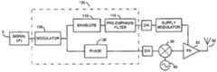
- FIG. 5is a block circuit diagram illustrating an exemplary topology of an envelope elimination and restoration (EER) transmitter having an increased bandwidth capability and reduced intermodulation distortion according to at least one embodiment of the invention
- FIG. 6is a Bode plot illustrating the amplitude and phase frequency response of a power supply modulator and the corresponding inverse amplitude and phase frequency response of the pre-emphasis filter according to at least one embodiment of the invention
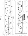
- FIG. 7is a series of graphs illustrating measured results of a data source signal in an EER transmitter using a pre-emphasis filter according to one or more embodiments of the invention including the signal before the supply modulator, the signal after the supply modulator without pre-emphasis applied, the signal before the supply modulator with pre-emphasis applied and the signal after the supply modulator with pre-emphasis applied.
- FIG. 8is a frequency domain plot of a simulation result of an EER transmitter using a DSB-SC AM signal with 500 kHz modulation bandwidth at 800 MHz RF with an 850 kHz envelope bandwidth both with and without pre-emphasis filtering applied in accordance with the various embodiments of the invention.
- FIG. 9is a flow chart outlining the steps of a method for enhancing bandwidth in an EER transmitter according to various embodiments of the invention.
- the transmitterincludes a signal source 5 for receiving a signal to be amplified and transmitted.
- An envelope detector 10receives the signal to be amplified and produces an envelope signal corresponding to the envelope of that signal.
- the envelope signalis fed to a power supply modulator connected to the power source input of a power amplifier 50 of the transmitter.
- the signal to be amplifiedis also received by a limiter 20 .
- the signal produced by the limiter 20contains the phase component of the signal to be amplified. This signal is supplied to the input of the power amplifier 50 and is amplified in accordance with the amplification level dictated by the power supply modulator.
- the power amplifier 50is coupled to an RF antenna 55 .
- FIG. 2is a block circuit diagram illustrating an exemplary topology of the conventional EER transmitter of FIG. 1 highlighting the supply modulator components that create the intermodulation distortion.
- the contents of the dotted circle surrounding the power amplifier 50 and corresponding signal and power inputsis shown in greater detail in the box above.
- the supply modulatoris used to reapply the input signal's envelope information to the amplified phase information by supplying a modulated power source to the signal corresponding to the input signal's envelope.
- the supply modulatorincludes low-pass filters for suppression of higher frequency harmonics. Loss of the high frequency content of the original signal produces intermodulation distortion when the phase and envelope signal are recombined in the amplifier.
- FIG. 3is a series of graphs depicting simulation results of a double sideband-suppressed carrier amplitude modulated (DSB-SC AM) signal in a conventional EER transmitter illustrating the results of intermodulation distortion on the resultant waveform.
- the first graph 71shows the source input, in this case, a DSB-SC waveform.
- the envelope signal of the DSB-SC signal 71is shown in graph 72 .
- the phase signal component of the DSB-SCis shown in graph 73 and is derived from the expression
- FIG. 4is a frequency domain plot of simulation results using a 10 kHz DSB-SC AM signal with a 20 kHz envelope using infinite envelope bandwidth and finite envelope bandwidth resulting in intermodulation distortion.
- the resultant signalis devoid of intermodulation distortion.
- the finite envelope path bandwidthresults in intermodulation distortion.
- the intermodulation distortionshows up as harmonic echoes around the desired signal, as shown on the right and left sides of 100 kHz frequency.
- FIG. 5a block circuit diagram illustrating an exemplary topology of an envelope elimination and restoration (EER) transmitter having an increased bandwidth and reduced intermodulation distortion according to at least one embodiment of the invention is depicted.
- the EER transmitterbegins with a signal source 5 and terminates with a power amplifier 50 connected to a RF antenna 55 .
- the power amplifier 50is modulated by a supply modulator in accordance with an envelope signal of the input waveform. Also, the phase component is fed to the power amplifier's 50 signal input.
- the transmitter of FIG. 5differs from the conventional transmitter in that logic block 100 includes a pre-emphasis filter 115 prior to the supply modulator that, in various embodiments, pre-emphasizes the envelope signal with the inverse frequency response of the supply modulator.
- the block 100may be implemented as a single circuit board, as a plurality of discrete circuit elements, or in programmable logic such as a field programmable gate array (FPGA).
- FPGAfield programmable gate array
- One or more of the block components 100may also be implemented as code executed by a digital signal processor (DSP).
- DSPdigital signal processor
- FIG. 6a Bode plot illustrating the amplitude and phase frequency response of a power supply modulator and the corresponding inverse amplitude and phase frequency response of the pre-emphasis filter according to at least one embodiment of the invention is depicted.
- the power supply modulatorhas a generally low pass frequency response, with a cut off frequency around 100 kHz.
- the pre-emphasis filterhas a frequency response that is generally high pass, passing frequencies above 100 kHz.
- This pre-emphasis filtercan be realized as shown in the figure as an infinite impulse response (IIR) digital filter.
- IIRinfinite impulse response
- FIG. 7is a series of graphs illustrating measured results of a data source signal in an EER transmitter using a pre-emphasis filter according to one or more embodiments of the invention including the signal before the supply modulator, the signal after the supply modulator without pre-emphasis applied, the signal before the supply modulator with pre-emphasis applied and the signal after the supply modulator with pre-emphasis applied.
- the first graph in FIG. 7shows the envelope signal before reaching the supply modulator.
- the second graphshows the same envelope signal after modulation by the supply modulator. As seen in this graph, the supply modulator has resulted in high-frequency distortion resulting from the low-pass filter response. The high-frequency transitions have been clipped.
- the third graph of FIG. 7shows the same envelope signal as the first graph, but with pre-emphasis filtering applied in accordance with at least one embodiment of the invention.
- the high-frequency enhancement resulting from the pre-emphasispre-biases the signal to prevent the affects of the supply modulator.
- the resulting post supply modulator signal shown in the fourth graph of FIG. 7shows a graph nearly identical to that of the first graph, that is, the original envelope signal prior to modulation. This resulting graph is devoid of the high-frequency distortion typically resulting from supply modulators in EER transmitters.
- FIG. 8is a frequency domain plot of measured results of result of an EER transmitter on a DSB-SC AM signal with 500 kHz modulation bandwidth at 800 MHz RF with an 850 kHz envelope bandwidth both with and without pre-emphasis filtering applied in accordance with the various embodiments of the invention.
- the comparison graph of FIG. 8shows approximately 18 dB reduction in intermodulation distortion when compared to the same system without pre-emphasis filtering.
- the measured results in the graph of FIG. 8show intermodulation distortion levels with and without pre-emphasis applied.
- the inventor of this inventionalso discovered that the applying the pre-emphasis filter also made the system robust to mismatch errors.
- a ten percent (10%) mismatch between the pre-emphasis filter and the system responseresulted in only 3 dB degradation in intermodulation reduction—that is, intermodulation reduction was still significant even in the presence of a 10% mismatch.
- Similar testingwas done with the same system as that shown in FIG. 8 , but with a DSB-SC AM signal with 50 kHz modulation bandwidth at 40 MHz RF with a 225 kHz envelope and a 850 kHz envelope bandwidth resulting in 11 dB and 16 dB intermodulation distortion respectively.
- FIG. 9is a flow chart outlining the steps of a method for enhancing bandwidth in an EER transmitter according to various embodiments of the invention.
- the processbeings in block 200 .
- a data source signalis received in the transmitter.
- the data source signalis any signal to be output by the EER transmitter.
- intermediate modulation (IM)is performed. This can be performed using any known modulation technique.
- the signalis split into envelope and phase paths.
- pre-emphasisis applied to the envelope signal.
- thismay comprise applying a pre-emphasis filter that has been designed/programmed to apply an inverse supply modulator frequency response to the transmit signal to pre-bias the signal to counter the modulator's unintended effects.
- the output of the pre-emphasisis supplied to the supply modulator.
- the phase signalis applied to the amplifier's input.
- the supply modulatormodulates the power supply (power amplifier) so that the phase signal is amplified according to the envelope signal's amplitude for transmission. The method stops in block 240 .
- the pre-emphasis techniques described herein in accordance with the various embodiments of the inventionreduce intermodulation distortion in an envelope elimination and restoration transmitter, and thereby increasing the effective bandwidth of these devices.
- the pre-emphasis techniques disclosed hereinmay be implemented at the circuit level in a variety of different manifestations including, as part of an intermodulation algorithm, just prior to reaching the power supply modulator in programmable logic (PLA, FPGA, etc.) or even in analog circuitry with little impact on existing EER transmitter designs and minimal additional power consumption.
Landscapes
- Engineering & Computer Science (AREA)
- Power Engineering (AREA)
- Computer Networks & Wireless Communication (AREA)
- Signal Processing (AREA)
- Physics & Mathematics (AREA)
- Nonlinear Science (AREA)
- Transmitters (AREA)
Abstract
Description
The phase signal undergoes phase reversal as shown in
When the envelope signal is low pass filtered as shown in
Claims (21)
Priority Applications (1)
| Application Number | Priority Date | Filing Date | Title |
|---|---|---|---|
| US11/512,256US7620377B2 (en) | 2006-08-30 | 2006-08-30 | Bandwidth enhancement for envelope elimination and restoration transmission systems |
Applications Claiming Priority (1)
| Application Number | Priority Date | Filing Date | Title |
|---|---|---|---|
| US11/512,256US7620377B2 (en) | 2006-08-30 | 2006-08-30 | Bandwidth enhancement for envelope elimination and restoration transmission systems |
Publications (2)
| Publication Number | Publication Date |
|---|---|
| US20080057881A1 US20080057881A1 (en) | 2008-03-06 |
| US7620377B2true US7620377B2 (en) | 2009-11-17 |
Family
ID=39152314
Family Applications (1)
| Application Number | Title | Priority Date | Filing Date |
|---|---|---|---|
| US11/512,256Expired - Fee RelatedUS7620377B2 (en) | 2006-08-30 | 2006-08-30 | Bandwidth enhancement for envelope elimination and restoration transmission systems |
Country Status (1)
| Country | Link |
|---|---|
| US (1) | US7620377B2 (en) |
Cited By (6)
| Publication number | Priority date | Publication date | Assignee | Title |
|---|---|---|---|---|
| US20060245517A1 (en)* | 2003-07-25 | 2006-11-02 | Matsushita Electric Industrial Co., Ltd. | Amplifier apparatus |
| US20090119554A1 (en)* | 2007-11-06 | 2009-05-07 | Agere Systems Inc. | Backplane emulation technique for automated testing |
| US20130109442A1 (en)* | 2011-06-08 | 2013-05-02 | Sriraman Dakshinamurthy | Methods and Systems for Pre-Emphasis of an Envelope Tracking Power Amplifier Supply Voltage |
| US8953711B2 (en) | 2013-06-04 | 2015-02-10 | Qualcomm Incorporated | Configurable pre-emphasis component for transmission circuitry |
| US9191250B2 (en) | 2013-11-26 | 2015-11-17 | Blackberry Limited | Extended bandwidth adaptive digital pre-distortion with reconfigurable analog front-ends |
| US9853600B1 (en)* | 2016-06-27 | 2017-12-26 | Raytheon Company | System and method for adaptive power modulation for power amplifier |
Families Citing this family (6)
| Publication number | Priority date | Publication date | Assignee | Title |
|---|---|---|---|---|
| US8300728B1 (en)* | 2008-09-24 | 2012-10-30 | Rockwell Collins, Inc. | Complex envelope elimination and restoration transmitter |
| KR101522644B1 (en)* | 2009-03-05 | 2015-05-26 | 삼성전자주식회사 | Apparatus and method for improving linearity of transmitter |
| US9442186B2 (en)* | 2013-05-13 | 2016-09-13 | Microsoft Technology Licensing, Llc | Interference reduction for TOF systems |
| CN105409117B (en)* | 2014-05-22 | 2018-08-14 | 华为技术有限公司 | Common local oscillator circuit, transmitting system and method of determining correction coefficients for common local oscillator circuit |
| US10462452B2 (en) | 2016-03-16 | 2019-10-29 | Microsoft Technology Licensing, Llc | Synchronizing active illumination cameras |
| JP6642154B2 (en) | 2016-03-17 | 2020-02-05 | 富士通株式会社 | Optical transmitter and method for transmitting optical signal |
Citations (15)
| Publication number | Priority date | Publication date | Assignee | Title |
|---|---|---|---|---|
| US6141541A (en) | 1997-12-31 | 2000-10-31 | Motorola, Inc. | Method, device, phone and base station for providing envelope-following for variable envelope radio frequency signals |
| US6151571A (en) | 1999-08-31 | 2000-11-21 | Andersen Consulting | System, method and article of manufacture for detecting emotion in voice signals through analysis of a plurality of voice signal parameters |
| US6275806B1 (en) | 1999-08-31 | 2001-08-14 | Andersen Consulting, Llp | System method and article of manufacture for detecting emotion in voice signals by utilizing statistics for voice signal parameters |
| US6377116B1 (en) | 2000-05-08 | 2002-04-23 | Iowa State University Research Foundation, Inc. | Pre-distorter and corresponding method for deriving same |
| US6538509B2 (en) | 2001-03-09 | 2003-03-25 | Dragonwave Inc. | Linearizer for a power amplifier |
| US6600369B2 (en) | 2001-12-07 | 2003-07-29 | Motorola, Inc. | Wideband linear amplifier with predistortion error correction |
| US6696866B2 (en) | 2002-07-24 | 2004-02-24 | Motorola, Inc. | Method and apparatus for providing a supply voltage based on an envelope of a radio frequency signal |
| US6725021B1 (en) | 2002-06-20 | 2004-04-20 | Motorola, Inc. | Method for tuning an envelope tracking amplification system |
| US6735419B2 (en) | 2001-01-18 | 2004-05-11 | Motorola, Inc. | High efficiency wideband linear wireless power amplifier |
| US6801082B2 (en) | 2002-12-31 | 2004-10-05 | Motorola, Inc. | Power amplifier circuit and method using bandlimited signal component estimates |
| US6826960B2 (en) | 2002-08-07 | 2004-12-07 | Quartz Sensors, Inc. | Triaxial acceleration sensor |
| US6868931B2 (en) | 1994-05-27 | 2005-03-22 | Deka Products Limited Partnership | Speed limiting for a balancing transporter accounting for variations in system capability |
| US20060240789A1 (en)* | 2005-04-25 | 2006-10-26 | Nokia Corporation | Reuse of digital-to-analog converters in a multi-mode transmitter |
| US7421037B2 (en)* | 2003-11-20 | 2008-09-02 | Nokia Corporation | Reconfigurable transmitter with direct digital to RF modulator |
| US7424064B2 (en)* | 2003-11-20 | 2008-09-09 | Nokia Corporation | Polar transmitter with digital to RF converter |
- 2006
- 2006-08-30USUS11/512,256patent/US7620377B2/ennot_activeExpired - Fee Related
Patent Citations (15)
| Publication number | Priority date | Publication date | Assignee | Title |
|---|---|---|---|---|
| US6868931B2 (en) | 1994-05-27 | 2005-03-22 | Deka Products Limited Partnership | Speed limiting for a balancing transporter accounting for variations in system capability |
| US6141541A (en) | 1997-12-31 | 2000-10-31 | Motorola, Inc. | Method, device, phone and base station for providing envelope-following for variable envelope radio frequency signals |
| US6151571A (en) | 1999-08-31 | 2000-11-21 | Andersen Consulting | System, method and article of manufacture for detecting emotion in voice signals through analysis of a plurality of voice signal parameters |
| US6275806B1 (en) | 1999-08-31 | 2001-08-14 | Andersen Consulting, Llp | System method and article of manufacture for detecting emotion in voice signals by utilizing statistics for voice signal parameters |
| US6377116B1 (en) | 2000-05-08 | 2002-04-23 | Iowa State University Research Foundation, Inc. | Pre-distorter and corresponding method for deriving same |
| US6735419B2 (en) | 2001-01-18 | 2004-05-11 | Motorola, Inc. | High efficiency wideband linear wireless power amplifier |
| US6538509B2 (en) | 2001-03-09 | 2003-03-25 | Dragonwave Inc. | Linearizer for a power amplifier |
| US6600369B2 (en) | 2001-12-07 | 2003-07-29 | Motorola, Inc. | Wideband linear amplifier with predistortion error correction |
| US6725021B1 (en) | 2002-06-20 | 2004-04-20 | Motorola, Inc. | Method for tuning an envelope tracking amplification system |
| US6696866B2 (en) | 2002-07-24 | 2004-02-24 | Motorola, Inc. | Method and apparatus for providing a supply voltage based on an envelope of a radio frequency signal |
| US6826960B2 (en) | 2002-08-07 | 2004-12-07 | Quartz Sensors, Inc. | Triaxial acceleration sensor |
| US6801082B2 (en) | 2002-12-31 | 2004-10-05 | Motorola, Inc. | Power amplifier circuit and method using bandlimited signal component estimates |
| US7421037B2 (en)* | 2003-11-20 | 2008-09-02 | Nokia Corporation | Reconfigurable transmitter with direct digital to RF modulator |
| US7424064B2 (en)* | 2003-11-20 | 2008-09-09 | Nokia Corporation | Polar transmitter with digital to RF converter |
| US20060240789A1 (en)* | 2005-04-25 | 2006-10-26 | Nokia Corporation | Reuse of digital-to-analog converters in a multi-mode transmitter |
Cited By (9)
| Publication number | Priority date | Publication date | Assignee | Title |
|---|---|---|---|---|
| US20060245517A1 (en)* | 2003-07-25 | 2006-11-02 | Matsushita Electric Industrial Co., Ltd. | Amplifier apparatus |
| US20090119554A1 (en)* | 2007-11-06 | 2009-05-07 | Agere Systems Inc. | Backplane emulation technique for automated testing |
| US7882404B2 (en)* | 2007-11-06 | 2011-02-01 | Agere Systems Inc. | Backplane emulation technique for automated testing |
| US20130109442A1 (en)* | 2011-06-08 | 2013-05-02 | Sriraman Dakshinamurthy | Methods and Systems for Pre-Emphasis of an Envelope Tracking Power Amplifier Supply Voltage |
| US9197175B2 (en)* | 2011-06-08 | 2015-11-24 | Broadcom Corporation | Methods and systems for pre-emphasis of an envelope tracking power amplifier supply voltage |
| US8953711B2 (en) | 2013-06-04 | 2015-02-10 | Qualcomm Incorporated | Configurable pre-emphasis component for transmission circuitry |
| US9191250B2 (en) | 2013-11-26 | 2015-11-17 | Blackberry Limited | Extended bandwidth adaptive digital pre-distortion with reconfigurable analog front-ends |
| US9853600B1 (en)* | 2016-06-27 | 2017-12-26 | Raytheon Company | System and method for adaptive power modulation for power amplifier |
| US20170373642A1 (en)* | 2016-06-27 | 2017-12-28 | Raytheon Company | System and method for adaptive power modulation for power amplifier |
Also Published As
| Publication number | Publication date |
|---|---|
| US20080057881A1 (en) | 2008-03-06 |
Similar Documents
| Publication | Publication Date | Title |
|---|---|---|
| US7620377B2 (en) | Bandwidth enhancement for envelope elimination and restoration transmission systems | |
| US8942649B2 (en) | Radio-frequency transmitter and amplifier | |
| US5838210A (en) | Method and apparatus for generating a modulated signal | |
| US6590940B1 (en) | Power modulation systems and methods that separately amplify low and high frequency portions of an amplitude waveform | |
| US8666325B2 (en) | Polar feedback receiver for modulator | |
| US20060178120A1 (en) | Transmitting/receiving device having a polar modulator with variable predistortion | |
| US20090060089A1 (en) | Polar modulation transmitter circuit and communications device | |
| US9602325B2 (en) | Transmitter and method of transmitting | |
| CN102368757B (en) | Predistortion circuit | |
| US6268818B1 (en) | Method and apparatus for improving modulation accuracy | |
| WO2012023624A1 (en) | Chireix power amplification method and transmitter using envelope-tracking power supply | |
| US8010063B2 (en) | Signal enhancement in RF transmitters employing non-linear filtering | |
| US7095799B2 (en) | Systems and methods for providing baseband-derived predistortion to increase efficiency of transmitters | |
| US9843345B2 (en) | Transmitter with quantization noise compensation | |
| CN100380823C (en) | Blind cancellation of cross modulation by adding modulated signal | |
| US20080317167A1 (en) | Generation of a Transmission Signal | |
| US7944321B2 (en) | Harmonic suppressing circuit | |
| US10637415B1 (en) | Linearity improving system and linearity improving method | |
| CN114978330B (en) | Feedforward post-compensation linearization radio frequency optical transmitter and improvement method thereof | |
| US8229029B2 (en) | Transmitter with reduced spectral regrowth and associated methods | |
| US8233850B1 (en) | Broadband power amplifier with partial-envelope transference | |
| EP2685689B1 (en) | Technique for generating a radio frequency signal based on a peak compensation signal | |
| US10652057B1 (en) | All digital outphasing transmitter | |
| GB2346773A (en) | Pre-clipping module for a non-linear high power amplifier | |
| Weldon et al. | Using amplifiers with poor linearity to linearize amplifiers with good linearity |
Legal Events
| Date | Code | Title | Description |
|---|---|---|---|
| AS | Assignment | Owner name:GENERAL DYNAMICS C4 SYSTEMS, ARIZONA Free format text:ASSIGNMENT OF ASSIGNORS INTEREST;ASSIGNOR:DWYER, RICHARD JAMES;REEL/FRAME:018245/0154 Effective date:20060822 | |
| STCF | Information on status: patent grant | Free format text:PATENTED CASE | |
| FEPP | Fee payment procedure | Free format text:PAYOR NUMBER ASSIGNED (ORIGINAL EVENT CODE: ASPN); ENTITY STATUS OF PATENT OWNER: LARGE ENTITY | |
| FPAY | Fee payment | Year of fee payment:4 | |
| AS | Assignment | Owner name:GENERAL DYNAMICS MISSION SYSTEMS, INC, VIRGINIA Free format text:MERGER AND CHANGE OF NAME;ASSIGNORS:GENERAL DYNAMICS MISSION SYSTEMS, LLC;GENERAL DYNAMICS ADVANCED INFORMATION SYSTEMS, INC.;REEL/FRAME:039117/0839 Effective date:20151209 Owner name:GENERAL DYNAMICS ADVANCED INFORMATION SYSTEMS, INC Free format text:MERGER;ASSIGNOR:GENERAL DYNAMICS C4 SYSTEMS, INC.;REEL/FRAME:039117/0063 Effective date:20151209 | |
| AS | Assignment | Owner name:GENERAL DYNAMICS MISSION SYSTEMS, INC., VIRGINIA Free format text:MERGER;ASSIGNOR:GENERAL DYNAMICS ADVANCED INFORMATION SYSTEMS, INC.;REEL/FRAME:039269/0131 Effective date:20151209 Owner name:GENERAL DYNAMICS ADVANCED INFORMATION SYSTEMS, INC Free format text:MERGER;ASSIGNOR:GENERAL DYNAMICS C4 SYSTEMS, INC.;REEL/FRAME:039269/0007 Effective date:20151209 | |
| FPAY | Fee payment | Year of fee payment:8 | |
| FEPP | Fee payment procedure | Free format text:MAINTENANCE FEE REMINDER MAILED (ORIGINAL EVENT CODE: REM.); ENTITY STATUS OF PATENT OWNER: LARGE ENTITY | |
| LAPS | Lapse for failure to pay maintenance fees | Free format text:PATENT EXPIRED FOR FAILURE TO PAY MAINTENANCE FEES (ORIGINAL EVENT CODE: EXP.); ENTITY STATUS OF PATENT OWNER: LARGE ENTITY | |
| STCH | Information on status: patent discontinuation | Free format text:PATENT EXPIRED DUE TO NONPAYMENT OF MAINTENANCE FEES UNDER 37 CFR 1.362 | |
| FP | Lapsed due to failure to pay maintenance fee | Effective date:20211117 | |
| AS | Assignment | Owner name:SUNCOR ENERGY INC., CANADA Free format text:ASSIGNMENT OF ASSIGNORS INTEREST;ASSIGNORS:HUQ, IFTIKHAR;ABBASPOUR, ALI;DOUCHETTE, BRIAN;AND OTHERS;SIGNING DATES FROM 20210303 TO 20221017;REEL/FRAME:062220/0445 |