US7620370B2 - Mobile broadband wireless access point network with wireless backhaul - Google Patents
Mobile broadband wireless access point network with wireless backhaulDownload PDFInfo
- Publication number
- US7620370B2 US7620370B2US11/623,110US62311007AUS7620370B2US 7620370 B2US7620370 B2US 7620370B2US 62311007 AUS62311007 AUS 62311007AUS 7620370 B2US7620370 B2US 7620370B2
- Authority
- US
- United States
- Prior art keywords
- backhaul
- node
- access
- network
- nodes
- Prior art date
- Legal status (The legal status is an assumption and is not a legal conclusion. Google has not performed a legal analysis and makes no representation as to the accuracy of the status listed.)
- Active, expires
Links
- 230000005540biological transmissionEffects0.000claimsabstractdescription157
- 238000000034methodMethods0.000claimsabstractdescription126
- 238000004891communicationMethods0.000claimsabstractdescription84
- 238000012545processingMethods0.000claimsdescription20
- 230000000116mitigating effectEffects0.000claimsdescription19
- 238000005259measurementMethods0.000claimsdescription11
- 238000013459approachMethods0.000claimsdescription9
- 238000000926separation methodMethods0.000claimsdescription9
- 238000013507mappingMethods0.000claimsdescription8
- 230000002829reductive effectEffects0.000claimsdescription8
- 230000010287polarizationEffects0.000claimsdescription7
- 230000003044adaptive effectEffects0.000claimsdescription6
- 230000002452interceptive effectEffects0.000claimsdescription6
- 235000008694Humulus lupulusNutrition0.000claimsdescription5
- 230000008878couplingEffects0.000claimsdescription4
- 238000010168coupling processMethods0.000claimsdescription4
- 238000005859coupling reactionMethods0.000claimsdescription4
- 230000005672electromagnetic fieldEffects0.000claimsdescription3
- 238000012544monitoring processMethods0.000claimsdescription3
- 230000008569processEffects0.000description32
- 230000003595spectral effectEffects0.000description26
- 230000001965increasing effectEffects0.000description25
- 238000009434installationMethods0.000description18
- 230000007246mechanismEffects0.000description18
- 238000007726management methodMethods0.000description17
- 238000001228spectrumMethods0.000description15
- 230000008859changeEffects0.000description12
- 230000008901benefitEffects0.000description11
- 230000006978adaptationEffects0.000description9
- 230000007423decreaseEffects0.000description9
- 238000005516engineering processMethods0.000description7
- 238000006243chemical reactionMethods0.000description5
- 238000009826distributionMethods0.000description5
- 238000001914filtrationMethods0.000description4
- 230000001360synchronised effectEffects0.000description4
- 238000012937correctionMethods0.000description3
- 238000010586diagramMethods0.000description3
- 230000006870functionEffects0.000description3
- 238000007781pre-processingMethods0.000description3
- 230000005855radiationEffects0.000description3
- 238000012546transferMethods0.000description3
- 239000000969carrierSubstances0.000description2
- 239000013256coordination polymerSubstances0.000description2
- 238000001514detection methodMethods0.000description2
- 230000000694effectsEffects0.000description2
- 230000005611electricityEffects0.000description2
- 230000002708enhancing effectEffects0.000description2
- 230000003179granulationEffects0.000description2
- 238000005469granulationMethods0.000description2
- 238000003780insertionMethods0.000description2
- 238000012423maintenanceMethods0.000description2
- 238000012360testing methodMethods0.000description2
- 230000007704transitionEffects0.000description2
- ODCKICSDIPVTRM-UHFFFAOYSA-N[4-[2-hydroxy-3-(propan-2-ylazaniumyl)propoxy]naphthalen-1-yl] sulfateChemical compoundC1=CC=C2C(OCC(O)CNC(C)C)=CC=C(OS(O)(=O)=O)C2=C1ODCKICSDIPVTRM-UHFFFAOYSA-N0.000description1
- 230000015572biosynthetic processEffects0.000description1
- 230000003139buffering effectEffects0.000description1
- 230000001413cellular effectEffects0.000description1
- 230000001427coherent effectEffects0.000description1
- 230000000052comparative effectEffects0.000description1
- 230000002860competitive effectEffects0.000description1
- 125000004122cyclic groupChemical group0.000description1
- 230000003247decreasing effectEffects0.000description1
- 230000001419dependent effectEffects0.000description1
- 238000013461designMethods0.000description1
- 230000036039immunityEffects0.000description1
- 230000003116impacting effectEffects0.000description1
- 230000006872improvementEffects0.000description1
- 230000037431insertionEffects0.000description1
- 238000011900installation processMethods0.000description1
- 230000010354integrationEffects0.000description1
- 238000002955isolationMethods0.000description1
- 238000005304joiningMethods0.000description1
- 239000011159matrix materialSubstances0.000description1
- 238000012986modificationMethods0.000description1
- 230000004048modificationEffects0.000description1
- 230000006855networkingEffects0.000description1
- 238000005457optimizationMethods0.000description1
- 230000036961partial effectEffects0.000description1
- 230000035515penetrationEffects0.000description1
- 229920001690polydopaminePolymers0.000description1
- 238000002360preparation methodMethods0.000description1
- 238000013139quantizationMethods0.000description1
- 230000009467reductionEffects0.000description1
- 238000005070samplingMethods0.000description1
- 238000007493shaping processMethods0.000description1
- 230000011664signalingEffects0.000description1
- 238000000638solvent extractionMethods0.000description1
- 230000003068static effectEffects0.000description1
- 239000002699waste materialSubstances0.000description1
Images


Classifications
- H—ELECTRICITY
- H04—ELECTRIC COMMUNICATION TECHNIQUE
- H04W—WIRELESS COMMUNICATION NETWORKS
- H04W28/00—Network traffic management; Network resource management
- H04W28/16—Central resource management; Negotiation of resources or communication parameters, e.g. negotiating bandwidth or QoS [Quality of Service]
- H04W28/18—Negotiating wireless communication parameters
- H—ELECTRICITY
- H04—ELECTRIC COMMUNICATION TECHNIQUE
- H04B—TRANSMISSION
- H04B7/00—Radio transmission systems, i.e. using radiation field
- H04B7/02—Diversity systems; Multi-antenna system, i.e. transmission or reception using multiple antennas
- H04B7/04—Diversity systems; Multi-antenna system, i.e. transmission or reception using multiple antennas using two or more spaced independent antennas
- H04B7/0413—MIMO systems
- H04B7/0417—Feedback systems
- H—ELECTRICITY
- H04—ELECTRIC COMMUNICATION TECHNIQUE
- H04W—WIRELESS COMMUNICATION NETWORKS
- H04W16/00—Network planning, e.g. coverage or traffic planning tools; Network deployment, e.g. resource partitioning or cells structures
- H04W16/02—Resource partitioning among network components, e.g. reuse partitioning
- H04W16/10—Dynamic resource partitioning
- H—ELECTRICITY
- H04—ELECTRIC COMMUNICATION TECHNIQUE
- H04W—WIRELESS COMMUNICATION NETWORKS
- H04W52/00—Power management, e.g. Transmission Power Control [TPC] or power classes
- H04W52/04—Transmission power control [TPC]
- H04W52/38—TPC being performed in particular situations
- H04W52/42—TPC being performed in particular situations in systems with time, space, frequency or polarisation diversity
- H—ELECTRICITY
- H04—ELECTRIC COMMUNICATION TECHNIQUE
- H04W—WIRELESS COMMUNICATION NETWORKS
- H04W92/00—Interfaces specially adapted for wireless communication networks
- H04W92/16—Interfaces between hierarchically similar devices
- H04W92/20—Interfaces between hierarchically similar devices between access points
- H—ELECTRICITY
- H04—ELECTRIC COMMUNICATION TECHNIQUE
- H04W—WIRELESS COMMUNICATION NETWORKS
- H04W16/00—Network planning, e.g. coverage or traffic planning tools; Network deployment, e.g. resource partitioning or cells structures
- H04W16/18—Network planning tools
- H—ELECTRICITY
- H04—ELECTRIC COMMUNICATION TECHNIQUE
- H04W—WIRELESS COMMUNICATION NETWORKS
- H04W72/00—Local resource management
- H04W72/50—Allocation or scheduling criteria for wireless resources
- H04W72/54—Allocation or scheduling criteria for wireless resources based on quality criteria
- H04W72/541—Allocation or scheduling criteria for wireless resources based on quality criteria using the level of interference
- H—ELECTRICITY
- H04—ELECTRIC COMMUNICATION TECHNIQUE
- H04W—WIRELESS COMMUNICATION NETWORKS
- H04W84/00—Network topologies
- H04W84/02—Hierarchically pre-organised networks, e.g. paging networks, cellular networks, WLAN [Wireless Local Area Network] or WLL [Wireless Local Loop]
- H04W84/04—Large scale networks; Deep hierarchical networks
- H04W84/042—Public Land Mobile systems, e.g. cellular systems
- H04W84/047—Public Land Mobile systems, e.g. cellular systems using dedicated repeater stations
- H—ELECTRICITY
- H04—ELECTRIC COMMUNICATION TECHNIQUE
- H04W—WIRELESS COMMUNICATION NETWORKS
- H04W88/00—Devices specially adapted for wireless communication networks, e.g. terminals, base stations or access point devices
- H04W88/08—Access point devices
Definitions
- the present inventionrelates to communications networks, in general and, in particular, to WiMAX communication systems.
- Broadband wirelessis expected to be one of the main drivers of the telecommunications industry. There is a substantial increase in demand for broadband connectivity, with personal broadband being the key growth engine for mobile wireless broadband networks.
- An access networkis the air interface network providing traffic communication between mobile terminals (subscribers) and their associated access points (base stations), while a backhaul network is the air interface network providing traffic communication between the various base stations and a core network.
- the networksmay be arranged to transfer data alone, as in Wi-Fi networks, or may be arranged for triple play services (video, audio and data), typically WiMAX (or other competitive technology, such as 3GPP-LTE).
- the access network and the backhaul networkeach require their own separate transmission equipment, antennas, etc, at great cost to the operator.
- the choice of backhaul technologymust take into account such parameters as capacity, cost and coverage.
- Base station backhaultypically is performed via wired infrastructure (e.g., E1/T1 leased lines), or via wireless Point-to-point (PTP) microwave links to each base station, which is expensive to deploy (equipment and installation).
- PTPPoint-to-point
- the backhaul components of conventional base stationsrequire strategic deployment location on high and expensive towers.
- OFDMOrthogonal Frequency Division Multiplexing
- single carrier technologyconstant power with a fixed modulation scheme
- Mobile WiMAXas defined in IEEE Standard 802.16e-2005 Standardization for WiMAX, was originally designed to provide mobile broadband access for mobile devices, i.e., broadband wireless data-optimized technology, providing carrier-grade triple play services using a variety of user devices (such as laptops, PDAs, handheld devices, smart phones, etc.).
- a complete mobile WiMAX Radio Access Network (RAN)requires deployment of massive infrastructure, including base station sites with high towers, base station equipment, antennas, and a separate backhaul network, as described above.
- the traditional approach for mobile WiMAX network infrastructure deploymentis similar to that of cellular phone networks.
- the networkis based on macro-cell deployment, that is, the base stations, radios and antennas are installed on top of high towers, transmitting at high power, so as to maximize the base station coverage area.
- the goalis to minimize the number of sites. This can be achieved by deploying more powerful base station equipment for increasing the cell range (e.g., high power radios, multiple radios on each sector with smart antenna techniques), resulting in more expensive base station equipment.
- this approachis adequate mainly for the coverage phase, when a relatively small number of subscribers share the cell capacity. As the cell coverage area is large, covering a large number of potential subscribers, additional subscribers in each area can rapidly be blocked due to limited base-station capacity.
- Wi-Fi networksdeployed mainly according to outdoor Wi-Fi mesh technology.
- the typical Wi-Fi setupcontains one or more Access Points (APs) (which is the equivalent terminology to Base Station in WiMax), having relatively limited range, deployed along telephone poles, street poles, electricity poles and rooftops. Due to the access point unit's smaller coverage range, a large number of access point units are required to cover a given area, typically between 20 to 30 access points per square mile, with wired backhaul at each 3 or 4 hops (known as micro or pico cell deployment).
- APsAccess Points
- WiMaxBase Station in WiMax
- Wi-Fi access point unitsrequire costly power amplifiers in each unit to extend the capacity in the downlink, but are still limited by link budget in the uplink, due to limited transmission power from mobile station units (such as a laptop, which typically transmits about 20 dbm on a single small integrated antenna) and due to the fact that Wi-Fi utilizes OFDM, where there is no spectral sub-channelization in uplink, which would enable enhancing the link budget.
- mobile station unitssuch as a laptop, which typically transmits about 20 dbm on a single small integrated antenna
- Wi-Fiutilizes OFDM, where there is no spectral sub-channelization in uplink, which would enable enhancing the link budget.
- conventional Wi-Fi networksoperate only on unlicensed bands, typically 2.4 GigaHz or 5 GigaHz bands, and suffer from severe interference and difficult radio-planning issues.
- the present inventionrelates to a wireless broadband communication network, herein illustrated by way of example only as a WiMAX® network, including a plurality of low cost, high capacity access point units deployed in micro or pico cells.
- Each access point unitprovides service to a plurality of mobile subscribers, and communicates with one or more other access point units, preferably, over an in-band, point to point backhaul network.
- the access point unitsare arranged in clusters, and coupled for multi-hop transmission.
- One access point in each clusteris designated as a feeder node and is coupled to the core network for providing backhaul to the core for the entire cluster, as well as coordination of the other access points in the cluster.
- the WiMAX network of the inventionincorporates also a point to point communication system providing a broadband wireless backhaul interconnection between access point nodes in the network.
- various nodescan communicate with one another, and not only with mobile subscribers or the core network, as in conventional networks.
- Each nodecan be an access point, a base station, a relay station, or any other infrastructure element which supports wireless infrastructure to infrastructure communication.
- Each nodepreferably includes a single controller (typically a MAC controller) for controlling and coordinating both access and backhaul communications in the node.
- a conventional backhaul networkpreferably a wired network, may be utilized to provide backhaul between the core network and each feeder node, which manages the cluster and distributes the traffic between the various nodes within the cluster.
- Each node's hardwarepreferably includes a plurality of radio transceivers with associated modems which are controlled by the MAC controller.
- the method and system of the inventioninvolve the use of multiple omni-directional antennas in each access point, one coupled to each modem.
- Each nodehas two modes of operation—access communication to mobile stations and backhaul communication between access points and towards the core. In access, using omni antennas, each node can provide up to 3 sectors for concurrent transmission.
- the MAC controllerphysically manages the node, although, logically, each antenna group or each sector is driven by a different MAC instance, which manages the modem and radios associated with that group.
- Thissimulates a low cost directional antenna with high link budget, to reach up to 400 meter cell coverage.
- omni antennaspermit multiple concurrent transmissions over multiple antennas in backhaul, for example, MIMO (Multiple In Multiple Out) for point-to-point transmissions over a single link, and SDMA (Spatial Division Multiple Access) for point to multi-point transmissions over several spatially separated links between an access point and its associated mobile stations (subscribers).
- MIMOMultiple In Multiple Out
- SDMASpatial Division Multiple Access
- a WiMAX networkincluding a plurality of WiMAX nodes deployed in micro or pico cells for providing access service to a plurality of mobile subscribers; a plurality of these nodes being arranged in a cluster; one of the nodes in each cluster being a feeder node coupled to a core network; the nodes in each cluster being coupled for multi-hop transmission to the feeder node.
- each nodeincludes a housing; a plurality of omni-directional antennas mounted on the housing; a plurality of transceivers mounted in the housing, each transceiver having an associated modem and being coupled to one of the antennas; and a chip including a MAC processor which directs and coordinates operation of all other elements in the node; a packet processor coupled to an inlet of the MAC processor for providing packets to the modem with air interface attributes; a routing table in the MAC processor for routing packets passing therethrough; a burst modulator coupled to the MAC processor for producing symbol busts for each sector over which that node is transmitting from a plurality of packets having at least some common air interface attributes; a symbol builder coupled to the burst modulator for receiving the symbol bursts and building an OFDM symbol according to a number of streams, sectors and antenna technique for transmitting each burst, and mapping each burst's symbols to frequency and time slots into an OFDMA time/frequency map;
- a method of WiMAX communicationincluding deploying a plurality of WiMAX nodes in micro or pico cells for providing access service to a plurality of mobile subscribers, arranging a plurality of these nodes in a cluster, coupling one of the nodes in each cluster to a core network to serve as a feeder node, and coupling the other nodes in each cluster for multi-hop transmission to the feeder node.
- FIG. 1is a schematic illustration of a wireless network constructed and operative in accordance with one embodiment of the present invention
- FIG. 2 ais a schematic illustration of a deployment topology according to one embodiment of the invention, transmitting over a MIMO link;
- FIG. 2 bis a schematic illustration of a deployment topology according to an alternative embodiment of the invention, transmitting over an SDMA link;
- FIG. 3 ais a plan view illustration of a wireless access point unit, according to one embodiment of the invention.
- FIG. 3 bis a schematic sectional view of the elements of the access point unit of FIG. 3 a;
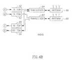
- FIG. 4is a block diagram illustration of an access point unit according to one embodiment of the invention.
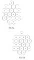
- FIG. 5 ais a schematic illustration of an antenna configuration according to one embodiment of the invention.
- FIGS. 5 b and 5 cillustrate two embodiments of sectorization by the antenna configuration of FIG. 5 a;
- FIG. 5 dis a schematic illustration of an antenna configuration according to an alternative embodiment of the invention.
- FIG. 5 eillustrates an embodiment of sectorization by the antenna configuration of FIG. 5 d
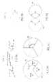
- FIG. 6 ais a schematic illustration of a 1:1 frequency re-use scheme
- FIG. 6 bis a schematic illustration of a 3:3 frequency re-use scheme
- FIG. 6 cis a schematic illustration of a 1:3 frequency re-use scheme
- FIG. 7illustrates smart connectivity MAC principles, according to one embodiment of the invention.
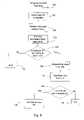
- FIG. 8is a flow chart illustrating backhaul time slot allocation, according to one embodiment of the invention.
- FIG. 9is a flow chart illustrating adaptive parameter selection, according to one embodiment of the invention.
- FIG. 10is a graphical illustration of time and frequency allocation (OFDMA), according to one embodiment of the invention.
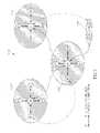
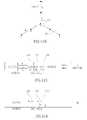
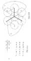
- FIG. 11 ais a schematic illustration of a fractional frequency re-use scheme, according to one embodiment of the invention.
- FIG. 11 bis a schematic illustration of a deployment of nodes in a cluster using the fractional frequency re-use scheme of FIG. 11 a;
- FIGS. 11 c to 11 gare schematic illustrations of time division among transmission frames in the cluster of FIG. 11 b;
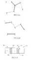
- FIGS. 12 a and 12 bare schematic illustrations of a MIMO configuration and a SDMA configuration, respectively, according to one embodiment of the invention.
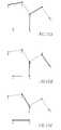
- FIGS. 13 a and 13 bare schematic illustrations of transmissions at different times on an SDMA configuration, according to one embodiment of the invention.
- FIG. 13 cis a schematic illustration of transmission frame according to the SDMA configuration of FIG. 13 a;
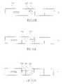
- FIG. 14 aillustrates a time division frame arrangement using a spatial interference mitigation scheme for an access point, according to one embodiment of the invention
- FIG. 14 bis a schematic illustration of the spatial interference mitigation scheme according to FIG. 14 a;
- FIGS. 15 a , 15 b and 15 care schematic illustrations of transmissions at different times on the spatial interference mitigation scheme of FIG. 14 a;
- FIG. 16is a flow chart illustrating radio resource re-use management, according to one embodiment of the invention.
- FIG. 17is a flow chart illustrating packet selection for transmission, according to one embodiment of the invention.
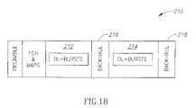
- FIG. 18is a schematic illustration of a transmission frame, according to one embodiment of the invention.
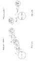
- FIGS. 19 a and 19 bare schematic illustrations of backhaul and access coordination in a cluster in a star configuration deployment, according to one embodiment of the invention.
- FIGS. 20 a and 20 bare schematic illustrations of backhaul and access coordination in a cluster in a multi-hop configuration deployment, according to one embodiment of the invention.
- FIG. 21 ais a flow chart illustrating transmitter power control, according to one embodiment of the invention.
- FIG. 21 bis a graphical illustration of transmitter power, according to the embodiment of FIG. 21 a;
- FIGS. 22 a and 22 bare schematic illustrations of transmission power control according to one embodiment of the invention.
- FIG. 23 ais a schematic illustration of the capacity distribution of a WiMAX cluster according to one embodiment of the invention.
- FIG. 23 bis a schematic illustration of the capacity distribution of a conventional WiMAX network.
- the present inventionrelates to a next-generation mobile broadband wireless network, particularly a wireless WiMAX network, having a plurality of access point nodes also serving as an internal backhaul network between the various nodes, i.e., base stations, relay stations, access points, etc.
- a next-generation mobile broadband wireless networkparticularly a wireless WiMAX network
- a wireless WiMAX networkhaving a plurality of access point nodes also serving as an internal backhaul network between the various nodes, i.e., base stations, relay stations, access points, etc.
- all the access and backhauling descriptionsrefer to any of these possibilities of infrastructure devices.
- an access networkis the air interface network providing communications between access points (base or relay stations) and mobile terminals, defined by IEEE802.16e-2005 standardization (WiMAX)
- a backhaul networkis the air interface network providing broadband wireless interconnection between access points within the network.
- each nodehas a single controller for controlling and coordinating access and backhaul communication.
- equipment for both access communication and point to point (PTP) backhaul communicationis built-in in a single module.
- PTPpoint to point
- the PTP communicationoperates over the same spectrum allocation (same frequency channel) that is used for access to the wireless subscriber terminals (“in-band” backhauling). This capability is particularly useful for deployments in licensed frequency bands, where the availability of extra spectrum for backhauling might impact the cost of deployment. With this solution, no additional separate frequency slice is required for the backhaul network, saving the costs of additional spectrum fees and frequency planning.
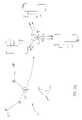
- the network 10includes a plurality of access point units 12 , each of which acts as a base station for its cell.
- the term access point unitrefers also to base stations and to relay stations.
- Deployment coverageis provided by a network of base stations, which is logically divided to multiple clusters 14 , 14 ′ (defined as a logically connected group of base stations).
- Each cluster 14is formed of a group of access point nodes 12 wirelessly interconnected to each other (as shown in heavy black lines), each of which provides wireless access to part of the cluster.
- each clusterone access point coordinates all the access points within the cluster and manages the backhaul network interference-mitigation scheme.
- This access pointis referred to as a feeder node 12 ′.
- the feeder nodes 12 ′ in each clusterare physically connected to the wired backhaul 16 and serve as the backhaul connection point of the whole cluster 14 to the core network (not shown).
- Each node 12provides access to wireless subscribers in its cell coverage area and communicates with at least one other node in the cluster, via the point-to-point communication of the invention, as described below. This communication can either be directly with the feeder node or via another node acting as a relay, to transfer its aggregated traffic towards the core network.
- the WiMAX network of the present inventionhas increased capacity with low cost infrastructure that provides both access and backhaul with high spectral efficiency, while reducing the effects of interference between links. This is accomplished by means of a low cost access point unit having a built-in backhauling mechanism connecting the access points to one another for relaying their aggregated traffic to the core network.
- the networkutilizes a high capacity point-to-point communication system between the access points, serving as the internal backhaul network between the various nodes in the network, i.e., base stations, relay stations, access points, etc.
- the high capacity in the PTP linkis achieved via methods of increasing the link spectral efficiency (transmitted bits/sec/Hz), although this compromises the link budget (maximum path loss with received transmission).
- thisis accomplished by performing high density modulation (QPSK to 256 QAM, at present) and providing multiple concurrent transmissions over multiple antennas.
- QPSKhigh density modulation
- multiple transmissionsare provided by creating virtual groups of omni-directional antennas, each group creating a beam at a certain beam width and transmitting a single stream.
- the spectral efficiencycan be increased using MIMO (Multiple In/Multiple Out) antenna techniques (adaptively allocating 1, 2 or 3 MIMO streams to different antennas) resulting in a PTP link with much higher spectral efficiency as compared to the average access network spectral efficiency, and the link budget can be improved by using beam forming with the omni-directional antennas.
- MIMOMultiple In/Multiple Out
- the access point units 12 of FIG. 1are deployed in micro-cell/pico-cell deployment configuration.
- Micro/pico cellsare defined as relatively small cells (typically 300-400 m radius in dense urban areas, as an example) installed in outdoor sites, typically on street lamp posts, telephone or electric poles, and rooftops, etc., as known in conventional outdoor Wi-Fi networks, as well as indoor sites, for in-building coverage extension and extra capacity requirements in indoor locations.
- Deployment topology of the access point unitsis preferably using a multi-hop relay topology, rather than macro-cell or mesh technology. This means that each mobile station is coupled to a core mobile network just by the feeder node, or by one or more relay nodes for data relay.
- each access point unit 12includes built-in, Point to Point backhaul, only a single box need be installed in each location, which results in easy and low cost site preparation (no need for preparing conventional wired backhaul from the core to each node, but only to one node in each cluster (the feeder)) and a low-cost installation (single unit installation).
- the unitcan be equipped with fewer antennas, such as 2 or 3 antennas, very similar to conventional Wi-Fi MIMO indoor units.
- the nodes in the cluster 14 of FIG. 1may be interconnected in a tree topology, the feeder node being the root of that tree, as illustrated schematically in FIG. 2 a .
- the topologyis preferably star, multi-hop or any combination of these two topologies.
- All traffic from all nodes 12 in the clusteris routed to and from the feeder node 12 ′, and then to the wired Internet network.
- the path from each node communicating with the feeder nodeis known and static under given link and network conditions. Alternatively, routing can also adapt itself due to traffic load sharing between nodes, interference conditions, and other deployment issues.
- one access pointcan communicate concurrently with multiple mobile stations in the same frequency band using SDMA (Space Division Multiple Access) techniques.
- the transmissionsare separated by different beam allocations, which are spatially separated due to geographic separation in deployment.
- SDMArequires multiple antennas on the feeder node and, theoretically, only one antenna on the other nodes.
- multiple antennas on the non-feeder nodeswill increase the link budget between nodes and, thus, improve the robustness of the deployment.
- a distributed Pico-cell deploymentprovides much higher capacity per area compared to a Macro-cell deployment, due to the fact that multiple cells are deployed over the same physical area.
- About 8 Pico-cell nodesare required to cover the same geographical area as a single Macro-cell, that is, the total capacity over the area is up to 8 times higher.
- the access pointcoordinates the mobile station access via WiMAX air bursts to the different mobile stations according to control bursts defined as MAP.
- the backhaul burstswill be allocated in pre-defined time slots for backhauling, as explained in detail below.
- the present networkhas standard compliancy in the air interface between mobile stations and the access points. In addition, it will support base station to base station communication on the same frequency channel and bandwidth during different periods within the frame, managed by the MAC controller. All backhauling processes are completely transparent to the WiMax air interface, as defined by IEEE 802.16e.
- each access point unithas self-planning capabilities, which include self-installation and self-interconnection in the network.
- Self-planning access pointsenable a new node joining the network to automatically configure its own RF parameters, both in terms of bandwidth and transmission parameters, such as antenna beam pattern width, antenna polarization selection, antenna beam direction, beam transmit power and MIMO data streams allocated to it, and in terms of route.
- This self-planning capabilityprovides significant benefits to the operator, as it saves frequency-planning costs (new planning for additional nodes in the network), eases the installation and decreases its costs, and enables a quick and inexpensive way to increase the network capacity by adding additional access points without requiring high installation costs.
- self-planningallows easy deployment of mobile broadband wireless communication infrastructure, such as WiMAX® infrastructure by a technician skilled in the art, and no specialist in telecommunication networks is required.
- a particular feature of the node hardware of a preferred embodiment of the present inventionis that the access and backhaul can be managed by a single Radio-PHY-MAC unit, utilizing the same resources (same hardware, same spectrum or frequency bank, and MAC functionalities) for both access and backhaul, and manipulating both traffic types on a frame by frame basis.
- a single scheduler(software algorithm) manages the traffic allocation to both the access point and PTP link portions of the frames, allocating traffic on each frame to each mobile station or backhaul node in accordance with a set of operator configurations for Quality of Service (QoS), which enables tight control of packet delay, packet delay jitter and packet rates for both backhaul and access.
- QoSQuality of Service
- each node in the networkincludes a WiMAX RF transceiver (including an RF transmitter and an RF receiver), a power amplifier for the relevant frequency band and power class, an RF filter bank switch to select the band of interest, a low noise reference frequency source and low noise amplifier, an RF filter to meet noise/spur standard requirements, and a transmit/receive switch with a suitable reference clock, as known.
- the transmitter and receiverare designed in Direct Conversion (zero IF transceiver) architecture, with direct up conversion/down conversion directly from the baseband signal to the RF signal, using a single active mixer.
- FIGS. 3 a and 3 bthere are shown respective plan view and sectional illustrations of a wireless next-generation mobile broadband node 30 , according to one embodiment of the invention, serving as an access point unit or base station (or relay station).
- Each node 30includes at least one and, preferably, a plurality of RF transceivers 32 for access to mobile stations within its coverage range, as well as for the high capacity backhaul point-to-point (PTP) link for communication with other nodes in the network.
- PTPpoint-to-point
- Each RF transceiver 32is coupled to an antenna 38 .
- antennas 38are omni-directional antennas, although alternatively, they can be directional antennas.
- a suitable modem 34is provided between each RF transceiver 32 and its associated antenna 38 . Both access and backhaul are coordinated and synchronized by a single controller 36 , here shown as a MAC controller, coupled to the transceivers via the modems, permitting utilization of the same hardware resources of the node, that is, the same radio, modem and antenna elements, for both access and backhaul.
- each node or access point unitis based on low-cost, standard off-the-shelf radio transceivers with power amplifiers (“terminal RF-IC” modules), such as those used at present in mobile consumer terminals.
- terminal RF-ICstandard off-the-shelf radio transceivers with power amplifiers
- each nodealso includes a plurality of low-cost standard omni-directional antennas 38 , preferably arranged in groups of 6, 9 or 12 antennas. Using these modules drastically reduces the access point unit cost. Therefore, the access point unit is a low-cost, low-power and small-form-factor unit.
- the low cost RF transceiversmay be those typically utilized in WiMAX mobile station handset units, which are designed, architecturally, to transmit low power.
- the radiois typically zero IF architecture, which requires compensation of I/Q phase misbalancing, gain misbalancing and DC offset.
- this type of transmissionintroduces distortion, I/Q DC offset/gain and phase imbalance, which must be treated in the modem (as by pre-compensation) and post-compensation (in the receiver). In one embodiment of the present invention, this is accomplished in a transceiver front end module, described below.
- This dynamic range requirementcan be improved by using a large bit analog to digital (A/D) converter and/or by increasing the sampling frequency, which decreases quantization noise by decimating the signal and filtering it.
- transmission powerpreferably is limited to the low power utilized in the mobile station. (Beam forming techniques can be used later to improve coverage or link budget by enhancing the power transmitted by the unit).
- a System-On-Chip (SoC) 40functions as the main building block of node 30 .
- the full network solutioncan be integrated into the SoC, enabling standard mobile access services, with a backhauling network connecting the access points to the network backbone.
- a memory 42is provided for storing the various algorithms for operation of the node, as well as a power supply 44 to supply the low power (about 7 W, at present) required by the node components.
- Node 30acts as a standard Mobile WiMAX 802.16e base station for access to WiMAX subscribers within its coverage range, as well as for the wireless backhaul link.
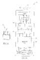
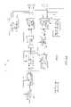
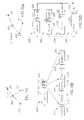
- FIG. 4there is shown a block diagram illustration of one exemplary embodiment of an access point unit 50 according to the invention.
- the heart of access point unit 50is its MAC processor 52 which directs and coordinates the operation of all the other elements in the unit.
- the MAC processor 52is responsible for all internal-external data transfer integrity. Data is received from two main directions—the receiver modem path and external network feeding (by Ethernet or similar connection). Receiver modem data is transmitted further to other base or relay stations or to mobile stations, or to an external network, if the unit is a feeder. Data received by an external network should be routed to either the air interface modem transmitter toward a target base station over the air, or toward a target mobile station over the air, or toward a network element outside the system.
- the MAC layerserves also as a general data path controller for link establishment, link maintenance, controlling and signaling between different wireless stations.
- the MAC processoralso validates all packet data passing through it in any direction.
- the packet processoris the heart of Quality of Service (QoS) based data flows and, when the access point unit is in transmit mode, provides data preprocessing and transmission preprocessing for MAC processor 52 , which is significant in building a high integrity data transport layer between any two wireless stations.
- QoSQuality of Service
- the integrity of received packetsis checked and, preferably, only error free, full packets are available for further data routing by the packet processor.
- Packet processor 54serves to receive and classify packets to be transmitted by access point unit 50 . All data packets (incoming and outgoing) are monitored, counted, enqueued according to QoS parametric configuration (a set of QoS classifiers), and stored until transmission.
- QoS parametric configurationa set of QoS classifiers
- the functions of the packet processorcan be accomplished by means of hardware or software, and preferably utilizing soft partitioning between hardware and software, such that bit manipulation and critical timing processes are carried out in hardware, while non-critical timing and protocol management are accomplished via software.
- All outgoing data to the modemis preprocessed by MAC processor 52 .
- the MACadds headers, block enumerations, encryption and other air interface controls to be used by the MAC processor of the receiving node. These controls are compiled at the transmitter and decompiled at the receiver. Outgoing data to the feeder generally needs less preprocessing.
- MAC 52decides, for each frame, from which queue to accept packets for transmission
- the MAC processorbuilds and stores a map of routes in the cluster from access point to access point. In addition, it periodically builds a routing table that defines which mobile station CID (connection ID) belongs to which access point according to this routing table and according to the topology built within cluster. The MAC knows the path to each CID and routes the packets along the required route.
- Each allocated packet from a queueis provided to the modem transmitter with air interface attributes, which may be selected from: modulation type (BPSK to 256QAM); antenna beam (which can be one of three sector beams, in access mode, or backhaul beam, while working in backhaul period); MIMO configuration; coding type and rate (such as CTC or PTC or CC at different rates, preferably as 1 ⁇ 2 or 1 ⁇ 3 or 2 ⁇ 3 or 3 ⁇ 4 or 5 ⁇ 6 or 7 ⁇ 8); in the case of a backhaul packet, which backhaul beam is selected, and if it is to a mobile station, toward which mobile station to transmit it, among others.
- modulation typeBPSK to 256QAM
- antenna beamwhich can be one of three sector beams, in access mode, or backhaul beam, while working in backhaul period
- MIMO configurationMIMO configuration
- coding type and ratesuch as CTC or PTC or CC at different rates, preferably as 1 ⁇ 2 or 1 ⁇ 3 or 2 ⁇ 3 or 3 ⁇ 4 or 5 ⁇
- the MAC processorcollects a set of packets with some of the same attributes (i.e., modulation, coding, stream, and antenna for access communications and, for backhaul packets, also having the same backhaul link) and sends the set of packets to a burst modulator 56 for processing the packets into bursts.
- the modem bursts and data capacitiesare dictated by a software scheduler in MAC processor 52 and defined in an air-map frame.
- Burst modulator 56is a high capacity burst modulator, and is responsible for the processing of the bursts configured by the MAC processor. Modulator processing includes bit randomization, coding, interleaving, repetition and modulation mapping. As known, the burst modulator process unit is a burst (a collection of frequencies over time). Each burst has physical layer attributes that define the exact processing that must be performed during processing. These attributes define the coding type (CTC, PTC, and CC) and rate, the modulation mapping (BPSK to 256QAM at present) and the repetition rate. These attributes are assigned by the MAC processor according to channel conditions and other link level parameters.
- the burst modulator 56produces symbol bursts for each sector over which the node is transmitting, ready to be processed toward the antennas 66 .
- One feature of the present inventionis that the same burst modulator 56 produces bursts for all the sectors, both access network and backhaul network, for all types of modulation, coding and MIMO streams. It will be appreciated the modulator 56 is differently configured for access and backhaul operation, according to MAC controller decisions, according to a destination air interface routing table and link conditions, such as SNR and interference measurements.
- the processed bursts built by the modulator 56are then passed to a symbol builder 58 that builds an OFDM symbol according to the number of streams, the sectors and the antenna technique that each burst should be transmitted with.
- Each burst's symbolis mapped to frequency and time slots into the OFDMA time/frequency map (described below) before transmission.
- each symbolis mapped in the frequency/time slot which was selected by the MAC processor for that transmission.
- the MIMO subsystemis responsible for all the signal processing related to the multiple input-multiple output communication (where input ⁇ output refers to streams per user or users that share the same time ⁇ frequency resources).
- Both backhaul and the multiple access communicationsmay require the support of one or more of four types of MIMO techniques in use today:
- the STC and MIMO multiplexing schemesmay use a pair of antennas (one from each triplet), while the triplet members may be used for sectorization within a cell.
- An antenna array and radio calibration module 61is provided for calibration of the transceivers and their associated antennas.
- the antenna array and radio calibrationutilizing narrow beam forming, or null steering or SDMA, should be employed to calibrate the phase and the amplitude of the radio chains between each other, in order to provide adequate beam forming/SDMA performance.
- Tx FEMtransmitter front-end module
- Transceiver 64is a radio transceiver well known in mobile stations (e.g., cell phones), having a low form factor, utilizing low power, and having low cost.
- mobile stationse.g., cell phones
- Such radio transceiversare manufactured and marketed by Analog Devices, Inc., Norwood, Mass., USA, e.g. AD9352 WiMAX/WiBRO RF MxFETM transceiver, and Maxim Integrated Products, Inc., Sunnyvale, Calif., USA, among others, and are standard, off-the-shelf devices.
- transmissionsare received via antennas 66 and transceiver 64 and amplified and down-converted to baseband signals or to IF signals, depending on the architecture of RF transceiver 64 .
- the incoming datais received in a receiver front end module (Rx FEM) 68 , which receives the OFDMA signal transmitted to it and performs the inverse operation of the TxFEM, such as Analog to Digital conversion, spectral filtering, automatic gain control, frequency/time/phase correction, CP de-insertion, FFT.
- This OFDMA signalis then processed by a multi-antenna synchronization module 70 coupled to a MIMO and beam forming receiver 72 .
- Multi-antenna synchronization module 70synchronizes carrier frequency, symbol timing frequency, power and phase of all the signals received by the various antennas (six, in a preferred embodiment of the invention). Synchronization is required due to the fact that all the receiver paths including MIMO beam forming should work on baseband coherent signals. It will be appreciated that calibration data is received in synchronization module 70 from calibration module 61 .
- the synchronized signalsare sent to MIMO receiver 72 , which implements an interference cancellation algorithm between multiple streams received from the six antennas.
- MIMO receiver 72implements an interference cancellation algorithm between multiple streams received from the six antennas.
- Thiscan be accomplished by well known algorithmic techniques, e.g., MMSE, SVD, BLAST, MMSE-SIC, MMSE-OSIC and other MIMO receiver techniques. It will be appreciated that different techniques may be used for access and for backhaul, since in backhaul it is possible to send channel side information via a robust feedback channel to the transmitter and use special beam forming to cancel interference in the transmitter, to significantly improve MIMO performance and reduce inter-stream interference.
- the signalsgo to a symbol de-builder 74 , where a group of OFDM symbols is de-mapped in time and frequency, either to a set of bursts (in access), as defined by the MAC processor, or, in backhaul, to the control channel defined during backhaul interconnection.
- the burstsare processed in a high speed burst demodulator 76 , which performs symbol soft decoding, de-interleaves the burst, in case of repetition coding, combines repeated symbols in the time domain (and performs MRC on it), decodes it according to specific coding type, such as CTC or PTC or CC, and de-randomizes it to produce data packets which go to MAC processor 52 for further processing.
- All incoming data to the MAC processor 52 from the modemhas to be checked for data integrity.
- Internal (RX modem) datais stripped from MAC headers and subheaders, decrypted (for encrypted data), checked for data continuity, retransmissions and other data inconsistency errors.
- the MAC processorassembles the packets from one or more data receptions from the modem RX path. Only error free, full packets are now available for further data routing by the packet processor 54 .
- the data flow countersare updated to reflect the status of the packet buffer inside the access point unit.
- the MAC processorperforms QoS algorithms for traffic monitoring in the transmission path out of the node to another node or to the wire line network toward the Access Service Network Gateway (ASNGW). Packets are usually discarded after being transmitted, but may also be discarded based on long waiting in queues.
- ASNGWAccess Service Network Gateway
- the network's peak throughputcan be higher than 200 Mb/sec.
- the unitincludes embedded ARQ (automatic repeat request), which is known in the art.
- ARQneeds a close relation between the physical (modem) layer and the data layer.
- a high speed ARQenforces embedding some of the ARQ processing in the MAC hardware section.
- Antenna Configuration(Sectorization, MIMO, Beam Forming)
- a sectoris a logical entity (segment of bandwidth) managed by a single virtual MAC (MAC instance) and a modem functionality (physically including an antenna front end module, MIMO beam forming device and RF transceiver and antennas).
- Cell sectorizationis associated with applying several PHY ⁇ MAC entities to a cell (e.g., three sectors per cell), where each sector gives service to a centralized zone in the cell, preferably 120° sectors.
- the antenna configuration in the system of the present inventionallows inherent sectorization within a cell, by using directional antennas, or by use of beam forming techniques which control the radiation of the beams from omni-directional antennas.
- Virtual antenna sectorizationpermits the use of low cost omni-directional antennas, where the antennas utilized act as directional antennas towards each sector.
- the MAC processor in each nodeknows how to decide which mobile station (or relay station) transmits or receives on each beam from each antenna.
- One embodiment of a method for associating a user with the sector that will serve itis accomplished by measuring the receiver's ability to receive and detect service from the given sector.
- the MIMO/Beam Forming Receiverhas knowledge of detection quality of a given user from all the sectors existing in the cell. These criteria may be based on semi-static measurements (e.g., long averaged CQI (Channel Quality Information, such as RSSI, SNR and CINR), dynamic measurements (e.g., Channel Side Information (CSI)) or measured interference criteria.
- semi-static measurementse.g., long averaged CQI (Channel Quality Information, such as RSSI, SNR and CINR)
- dynamic measurementse.g., Channel Side Information (CSI)
- the nodemay obtain the required information explicitly (e.g., by user feedback) or implicitly, based on channel reciprocity (e.g., by sounding).
- Other techniquesincluding DoA (direction of arrival), DoD, MRC, MMSE, or others, can alternatively be used for detection of best antenna beam service for the mobile station.
- the MAC processorbuilds a database of all the subscribers in the network and their location in space (for both access and backhaul), which is used for directing bursts to the various sectors.
- the MAC processorconfigures the direction of the bursts for those mobile stations, and sends instructions to the burst modulator, the symbol builder and the MIMO beam former, and modem transmitter for transmission.
- each access point unitmay include 6, 9 or even 12 antennas
- the access point unitincorporates six radio hardware chains, each of which transmits and receives RF signals to/from one of the six antennas, and the modem transmits signals over the six antennas to perform sectorization via beam forming techniques or MIMO.
- MIMObeam forming techniques
- six complete channelsare formed for smart antenna manipulations, such as beam-forming, and antenna diversity schemes, such as maximum Ratio Combining or STC, thus gaining range extension, reduced fade margin and improved link performance in multi-path conditions.
- the direction and width of the beamare dictated by the antenna physical location and antenna characteristics.
- the use of omni-directional antennaspermits later selection of beam characteristics by forming virtual antenna groups, using smart antenna techniques configurable by software.
- a bit stream (data or symbols) to be transmittedcan be transmitted over a link by all the antennas in the node or by sub-groups of antennas (e.g., 2, 3 or 6, depending on the total number of antennas in the node).
- sub-groups of antennase.g. 2, 3 or 6, depending on the total number of antennas in the node.
- transmission of the same stream (1 stream) over all the antennaswill improve the SNR, and the spectral efficiency will increase in proportion to the improvement in SNR.
- the bit streamcan be split into two or more MIMO streams by the modem (PHY) in the node, then the rate can be doubled (or higher) by transmitting more than one symbol on the same frequency at the same time. This, of course, will reduce the link budget per stream, which will reduce the SNR per stream.
- Each MIMO streamis allocated an appropriate grouping of antennas, according to the network and/or the link configuration. Transmitting multiple streams can be accomplished when the streams are spatially separated. This separation can be gained by physical geometry separation between antennas or by rich scattering contributed by the channel, or where the streams are separated by polarization of the electromagnetic fields of the antennas, such that each stream has a different polarization, or by any other means of parallelization of the streams within predefined channels. Thus, the capacity can be increased by a factor of the number of streams since, when utilizing MIMO techniques, each receiving antenna can cancel adjacent stream interference, so as to properly receive the stream that was directed to it.
- One proposed antenna configurationinvolves allocating antennas to create two groups 80 , 82 of antennas, each having three omni-directional antennas arranged in a triangle (as shown in hardware in FIG. 3 a ).
- the antenna groups 80 and 82are spatially separated, with the distance d between antennas in each group typically being lambda/2, with distance L between two groups, typically >5 lambda.
- two groups of three omni-antennascan be utilized at smaller spatial distances, i.e. L ⁇ 5 lambda, with polarization, i.e., one group being vertically polarized and the second being horizontally polarized, as when there is a 90° mechanical angular spatial separation between the antennas.
- each group of antennasgenerates three beams 84 (of 120° each) using beam-forming, as shown schematically in FIG. 5 b .
- a diversity scheme between the two groups of antennasis preferably employed, using transmit and receive diversity methods, such as STC (Space Time Coding), CDD (Cyclic Delay Diversity), MRC (Maximum Ratio Combining), selection diversity, which provide enhancement of the link budget, resulting in increased SNR and increased spectral efficiency.
- STCSpace Time Coding
- CDDCyclic Delay Diversity
- MRCMaximum Ratio Combining
- selection diversitywhich provide enhancement of the link budget, resulting in increased SNR and increased spectral efficiency.
- each beamscan form three virtual sectors, where each virtual sector transmits and receives in a different frequency range.
- Beam-formingcan also be used for sub-sectorization of each sector into two sub-sectors (additionally increasing the link budget), to provide essentially six sectors 86 , as shown in FIG. 5 c .
- This techniqueis useful, in access only, to increase link budget.
- each sub-sectoris 60° (360°/6), so each pair of beams forms a sector and uses the same frequency group.
- twelve antennasare required, six antennas for 60° sub-sector and six antennas for the additional stream.
- the pairs forming each sectorare illustrated as being adjacent to one another, but they are not limited to such configuration.
- the beam widthcan be 360/3 or 120°.
- the rateis twice the rate of one stream and the spectral efficiency is twice that of one stream.
- the beamis wider, causing the link budget to go down.
- each streamis transmitted to and from two antennas at a beam width of 360/2 or 180°, resulting in three times the spectral efficiency but much lower link budget and more difficult reception.
- This optionrequires an antenna configuration of three pairs of antennas (not illustrated).
- Each antennacan be arranged for 1, 2 or 3 MIMO streams having beam widths as follows, when using omni-directional antennas:
- antennas1 stream 60° 2 streams 120° 3 streams 180° 9 antennas: 1 stream 40° 2 streams 80° 3 streams 120° 12 antennas: 1 stream 30° 2 streams 60° 3 streams 90°
- An alternative proposed configurationis 6 antennas 88 arranged in a circle, as shown in FIG. 5 d .
- two beams 89 of 60°are generated by the six antennas.
- Only beam forming for single transmissions or SDMA for multiple concurrent transmissions(described in detail below) can be utilized. (Since these antennas are not sufficiently separated spatially, MIMO cannot be utilized.)
- Another alternative embodimentis to utilize a plurality of directional antennas. For example, using directional antennas of 90° each, the angle of each antenna should be 90° divided by the number of antennas times the number of streams.
- the number of antennasis configurable (i.e., selected in advance and fixed in the hardware)
- the number of streamspreferably is dynamic and adaptive, and is adjusted over time.
- 1, 2 or 3 MIMO streamsare adaptively allocated to different antennas, depending on measured link conditions, and the bandwidth beam pattern (from 180 degrees to 60 degrees) is selected to improve link budget.
- the number of streamsis selected depending on the amount of interference, noise, signal strength (RSSI), CINR (Carrier to Interference and Noise Ratio), etc., at any given time along the link. Accordingly, the number of streams can change periodically, although not necessarily in real time.
- each access point node in the networkpreferably provides statistical information to the transmitter in the other node on its link required in order to permit adaptive allocation of not only MIMO streams, but also of modulation and coding, as described below.
- the novel WiMAX networkis fully WiMAX compliant. It includes a 802.16e-compliant base station, having full PHY and MAC features, as per 802.16e wave 2 WiMAX profile or any WiMax profile which will be adopted from time to time. It supports optional base station features in wave 2 (IO-BF, IO-MIMO). In addition, it supports channel bandwidths of 3.5, 5, 7 and 10 MHz, and supports WiMax Networking architecture and interfaces. Furthermore, the network is transparent to WiMAX and to other wireless networks.
- the network of a preferred embodiment of the present inventionis characterized by self-learning, which permits self-installation and self-interconnection of nodes.
- a self-installed WiMax access point networkeliminates the need for deployment network planning, i.e, frequency planning, antenna direction alignment, antenna width tuning, and power allocation to each sector, each of which is required in conventional systems. This is accomplished by means of a mechanism which performs self learning during deployment by determining physical layer parameters of neighboring base stations, and selecting its own physical layer parameters in accordance therewith. This mechanism is described briefly below, and in detail in Applicant's co-pending application entitled ACCESS POINT PLANNING MECHANISM.
- a network planis devised, indicating locations of feeder nodes, based on coverage predictions.
- a default configuration for beginning workis programmed into the feeder nodes, and the feeder nodes are coupled to the data feeder (wired backbone).
- a clusterization network planis also set—i.e., whether multiple clusters forming the network will utilize the same frequency, or whether a frequency re-use scheme (typically, re-use 1:3 or re-use 1:1 or re-use 3:3) (described in detail below) will be utilized.
- Each access point in the networktransmits within its selected bandwidth. When a new access point enters the network, it must first receive transmissions from all the access points already around it in the network.
- Self-installationis enabled by self-planning algorithms utilizing smart antenna technologies. As part of its self-installation process, each access point unit performs space and frequency channel sounding, so as to produce an “RF spatial map” of the environment frequencies, i.e., on which frequencies which near-by access point units are broadcasting.
- the access pointautomatically detects WiMax 802.16e physical layer parameters of the clusters around it, including the existence of a frequency re-use scheme, and whether any WiMax frame permutation methods—PUSC, FUSC or AMC schemes—are in use. It also detects beam direction of departure from the edge access points of each of the surrounding clusters, as well as the beam width and pattern and sectorization beam center.
- WiMax 802.16e physical layer parameters of the clusters around itincluding the existence of a frequency re-use scheme, and whether any WiMax frame permutation methods—PUSC, FUSC or AMC schemes—are in use. It also detects beam direction of departure from the edge access points of each of the surrounding clusters, as well as the beam width and pattern and sectorization beam center.
- the new access pointBased on the signal strength, direction and other selected parameters of the signals received, the new access point selects the appropriate physical layer parameters for itself, including bandwidth (frequency range), FFT size, guard time used, permutation scheme, directions of beam arrival and the distribution of the beam in space, as well as beam power, for each sector of its own access transmissions, as well as the frequency to be assigned to each virtual sector (in case of re-use 1:3).
- bandwidthfrequency range
- FFT sizefrequency range
- guard time usedguard time used
- permutation schemedirections of beam arrival and the distribution of the beam in space, as well as beam power, for each sector of its own access transmissions, as well as the frequency to be assigned to each virtual sector (in case of re-use 1:3).
- one preferred embodimentemploys software that controls the modem and radio performance, in order to incorporate a Spatial Spectrum Analyzer, which enables spatial spectral interference management.
- the new access pointdetermines which frequency or frequencies are available in which directions, with the least interference from adjacent access points, and then utilizes beam-forming techniques to maximize its own coverage. Interference management is based on the principle that fixed beam forming in access generates a constant interference pattern, and constant interference is manageable.
- the access points of the present inventiontake advantage of interference knowledge, and utilize power control, and sub-channel management, as well as null steering (spatial filtering in Up Link and Dl Link) and in-band sub-channel selection in Down Link, for interference management, as known. Additional techniques that can be used for interference management in the access network include frequency re-use as described below and use of multiple sectors as described above.
- the network of the present inventionsupports several radio access network deployment frequency re-use schemes.
- the frequency re-use schemedefines the division of bandwidth (frequency channel) between sectors of a cell or between entire cells.
- a frequency reuse of 1:1implies that all cells use the same sub-carriers (frequency band or sub-band) F across their borders, as illustrated in FIG. 6 a .
- FIG. 6 bAn alternative re-use 3:3 is shown in FIG. 6 b , where each cell in each group of 3 cells utilizes a different frequency band or sub-band f 1 , f 2 , f 3 (out of 3 possible bands). This arrangement provides increased link budget in each cell at the expense of capacity of each cell, which is reduced to one third.
- a frequency re-use scheme of 1:3, as shown in FIG. 6 cindicates that each cell is divided into three sectors, and each sector operates in a different frequency band or sub-band (1 ⁇ 3 of the spectrum) f 1 , f 2 , f 3 , with coordination between cells to minimize interference.
- beam-formingis used to perform virtual sectorization, as described above. This approach minimizes inter-cell interference, though the peak spectral efficiency is degraded by 3 on each sector, thus each sector peak rate is reduced by 3.
- the frequency re-use schemewill be selected depending on the network deployment topology.
- Re-use 1:3is the default re-use scheme for use by the access point.
- the available bandwidthis divided to 3 groups of bandwidths, each driven by a separate MAC instance (virtual portion of the MAC controller) or preferably, the MAC controller manages three MAC instances, one for each virtual sector.
- a single controllercoordinates and controls all three groups. Power management on each sub-carrier, sub-band or band is provided to control access point density topology and network interference management.
- this processcan be implemented manually, by an operator, rather than automatically by the access points of the system.
- this processcan be utilized with or without other processes and mechanisms described in this application.
- self-installationis an option which provides advantages in the network, but it is not required.
- a new access point node 112when added to the network 110 , it first undergoes installation in the access network (either self-installation or manual installation by an operator), which means that it performs multiple access beam forming adaptation and power adaptation to enter the existing re-use deployment scheme.
- the new access pointnow undergoes self-interconnection (or manual interconnection by an operator), in order to enter the backhaul network, as illustrated schematically in FIG. 7 .
- the feeder nodewill allocate to the new access point a backhaul time slot within the cluster.
- the self-interconnection processis substantially as follows.
- the new access point 112must be synchronized with all the access points 112 ′, 112 ′′ around it in the cluster that are transmitting a downlink signal in its range of frequencies.
- the access pointmaps the various access point transmissions, the angle of arrival from each access point, signal to noise ratio (SNR) over all the routes toward one or more feeders in its range, available capacity, interference metrics, and other selected parameters.
- SNRsignal to noise ratio
- a router 114may be provided to feed data to the feeder. (The router is above the WiMAX air interface network.)
- a feeder nodewill select the best route to it for the new access point. This will be the route on which the new access point entering the cluster will experience the best throughput performance without substantially reducing the feeder node capacity. In case there is a conflict between these two requirements, the feeder node capacity has higher priority.
- the new access point 112now connects to the selected access point 112 ′ (which may be the feeder node or another access point (relay node) which is, itself, coupled to the feeder node), as if it were a mobile station.
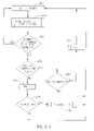
- the self-interconnection process of an access point (AP) to the backhauling networkis illustrated in block diagram form in FIG. 8 . While the access point underwent self-installation, it performed pre-selected physical layer scans (beams, azimuths, frequencies, modem specifics parameters, etc.) and located one or more access points transmitting on different frequencies (block 120 ).
- the self-installing access pointselects the best access point to communicate with (block 122 ) based on link conditions, and performs a standard 802.16e network entry registration (block 124 ) as a ‘Special Mobile Station’, which includes ranging processes, capability negotiation, etc., ending by registering to the preferred access point.
- the selected “best” access pointis not an access point according to the invention (block 128 )
- the new access pointcontinues to provide access services to its mobile stations, and continues to seek a backhaul connection elsewhere, thus ending the registration process (block 130 ).
- the selected access pointis an access point according to the invention (block 128 )
- a special MAC messagewill be sent to the access point indicating this fact.
- the access pointwill now request the feeder to allocate to it a backhaul time slot (block 132 ).
- the relaywill forward the request to the feeder.
- the feedernow selects the best backhaul route to the feeder node and allocates temporary PHY and MAC parameters, such as available capacity, time slots, sub-carrier allocations and other interference and cluster-related parameters (block 134 ).
- the access pointsmeasure the interference in the entire cluster generated by transmission on the proposed link (block 136 ) to determine the level of interference generated (block 137 ). If the best connection for the access point results in interference for the cluster above a pre-selected threshold level, the feeder will reject the connection (block 139 ) and disconnect the new access point, and it will have to seek a different feeder in another cluster.
- the feederwill again perform interference mechanism in the cluster as described in detail below.
- This new routeremains as a fixed route until a change occurs within the access point clusters, or the feeder decides to change the route due to interference issues.
- the feeder nodesince the feeder node decides on the best route of hops to interconnect each access point with each other and with the feeder access point, once a backhaul time slot has been allocated to a new access point, the feeder must reconfigure the backhaul over the entire cluster, taking into account topology and interference measurements over the network.
- the feedernow re-allocates backhaul time slots between each link in its cluster using the mechanism described below.
- the routing protocolis controlled by the feeder access point such that the feeder sets up each route to each access point based on spatial interference between access points and within the frequency band interference. Periodically, the feeder access point can update the routing table for each access point to the feeder access point.
- the feeder access pointreserves a constant capacity (e.g., allocation of time over channel bandwidth) for each access point within the cluster. It should be noted that the feeder access point can learn the traffic requirements for each access point toward a route and dynamically optimize it, by adapting the capacity to each route based on a set of predefined operator rules, such as minimum delay to a predefined access point, prioritizing the access point within the cluster (access point class of service), access point minimum/maximum rate, average rate, constant rate requirement and any other additional rate management required by the operator.
- a connection-oriented protocolpreferably provides fully controlled latency and jitter ⁇ 1-2 frame constant delay.
- the feederPeriodically, the feeder measures the interference in its cluster during access transmissions and can adapt power, beam direction, PHY configuration and frequency in order to reduce the interference to the minimum level possible, under current conditions.
- the feederwill instruct whichever node is causing interference in the cluster to lower its power and measure again. It will be appreciated that, as additional access point units are added in a given area, in order to increase capacity, it is possible that the feeder node, itself, will be the node causing interference in the cluster. If this is the case, the feeder will reduce its own transmissions in access until the interference is resolved. Thus, in some cases, the feeder will no longer be required for access transmissions at all, but can devote itself to providing only backhaul services for all the relays in the cluster coupled to it. This mechanism for backhaul is described in detail below.
- Self-planningsaves the frequency planning costs from the operator.
- Self-planningis preferably performed automatically periodically, as well as upon any change event in the network. It is essential mainly when increasing the access point density (“capacity phase”) of the network.
- Another advantage of the present networkis that it is self-healing.
- the networkis resilient, and can reduce network failure substantially to a single point. Thus, if an access point discovers that it can no longer contact an adjacent access point, it will notify all the other access points in the cluster and adjust its own installation parameters accordingly.
- a protocolruns periodically between each feeder and its associated access points, to check that all registered access points still exist in the network, similar to a “keep alive” message transmitted periodically, which is acknowledged by each access point.
- each access pointalso can run a self connectivity “keep alive” to the access point it is attached to, to ensure that it is still connected to the network.
- the access pointdoes not receive any keep alive message from the cluster feeder for a pre-defined period of time, it will conclude that the adjacent access point is lost.
- the feeder node and other access points coupled to the lost access pointwill discover the absence of that access point.
- the disconnected access point or pointswill now undergo re-registration, self-installation and re-connection, as described above. It will be appreciated that, at this time, the access point may connect to a different access point or even to a feeder node in a different cluster, depending upon the operator strategy and the local conditions.
- interconnection process described aboveis automatic and self-contained within the various access points, thereby providing certain advantages to the network (particularly in cost and uninterrupted service). However, it will be appreciated that, alternatively, this interconnection can be accomplished manually by an operator. Thus, this process can be utilized with or without the other processes and mechanisms described in the present application.
- a single scheduler within each access point unitmanages both the access and backhaul.
- One example of a decision-making process of the scheduleris described in FIG. 17 .
- a packet received from a core networkis received in the scheduler after having been classified by the core network (block 200 ).
- the packetis parsed, and selected attributes (for example, addresses, QoS) are retrieved (block 202 ).
- Each packetis stored in a packet buffering element (e.g., a memory) (block 204 ) in a certain queue, according to its retrieved attributes.
- packet policingis utilized (block 206 ) to permit only an appropriate number of packets onto the link, to prevent port flooding and to limit the packet rate of each queue to the QoS rate required.
- the schedulernow decides which packets in which queues are to be transmitted over backhaul to the destination access point, and which packets are to be transmitted over their access links, in each frame (block 208 ).
- the frame builder in the MACbuilds each frame with the selected packets, for both backhaul and access, for transmission over the air (block 209 ).
- the in-band backhaulingmay be performed by allocating a time slot for backhaul traffic (a ‘Backhaul period’) in each WiMAX frame 210 .
- the WiMAX frame 210may be divided into an ‘Access period’ 212 for downlink and an ‘Access period’ 214 for uplink, and a ‘Backhaul period’ 216 for downlink and a ‘Backhaul period’ 218 for uplink.
- the access period and the backhaul periodare coordinated and synchronized, thus avoiding interference between the access communication and the backhaul communication, even while they are operating over the same frequency.
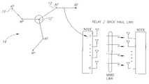
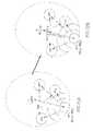
- FIG. 19 athere is shown an example of 4 nodes in a star topology.
- the feeder 220is coupled to, and controls transmission of, three access points 222 , 224 , 226 each of which, in turn, is coupled to a plurality of mobile stations (not shown).
- Associated transmission framesare illustrated schematically in FIG. 19 b .
- the frame of feeder 220has a time slot 228 for access and three time slots 230 , 232 , 234 for backhaul, one for backhaul communication with each access point 222 , 224 and 226 .
- each of the access points 222 , 224 , 226has a corresponding backhaul slot 230 ′, 232 ′ or 234 ′, and an access time slot 236 (or two) longer than that of feeder 220 , since each access point can provide access communication during the entire period when it is not communicating with the feeder 220 (backhaul).
- the star-3 topologyassumes a 2 stream MIMO configuration in a point-to-point backhaul link and a spectral efficiency factor of about 8 times higher than the average access spectral efficiency.
- the duration of the backhaul period in the frameis 12.5% of the duration of the access period per backhaul link.
- the average capacity waste due to backhaul overheadis about 20%, while the overall network average node capacity is about 80% of the maximum node capacity.
- a multi-hop topologycan be utilized.
- FIG. 20 athere is shown an example of 4 nodes in a multi-hop topology.
- the feeder 240is coupled to, and controls transmission of, an access point 242 and a relay 244 which, in turn, is coupled to access point 246 .
- each of the nodesis coupled to a plurality of mobile stations (not shown). Mapping of access and backhaul frames over these four access points is illustrated schematically in FIG. 20 b .
- the frame of feeder 240has a time slot 248 for access and two time slots 250 , 252 for backhaul, one for backhaul communication with access point 242 and one for backhaul communication with relay 244 and, through the relay, with access point 246 .
- both uplink and downlink time slotsare provided in the frame, although only one is illustrated.
- the frames of each of the access points 242 , 244 , 246has a corresponding backhaul slot 250 ′, 252 ′ or 254 ′, and an access time slot 266 (or two) longer than that of feeder 240 .
- the backhaul slot of relay 244is of the same length as slot 252 of the feeder, since relay 244 must provide backhaul communication both for itself and for second tier access point 246 .
- the Point-to-Point (PTP) backhaul link used for inter-access point interconnectionhas a significantly higher capacity compared to the average aggregated node access capacity (which can be on the order of 6-12 times higher).
- PTPPoint-to-Point
- a “narrow” time slotis sufficient for backhauling all the aggregated traffic of the node, even when relaying the entire traffic of another node, resulting in low overhead on the node.
- this methodwhen utilizing frequency re-use or division schemes, can lead to a large number of time slots for transmitting and receiving access communications and for transmitting and receiving backhaul communications, requiring many transitions from transmission to reception in each frame. This can be problematic, due to the hardware limitations regarding the time required for conventional transceivers to convert from one to the other. Accordingly, it would be desirable to provide a method for minimizing the number of transitions between transmission and reception in such cases. According to one embodiment of the present invention, this can be accomplished by the feeder MAC causing the frame builder to build each frame with all transmission time slots adjacent one another and all receiving time slots adjacent one another. Preferably, consecutive frames begin with the same state of the transceiver as the previous frame ended. While this embodiment has great advantages in terms of efficiency of the overall network, it requires coordination throughout the network of the various feeder MACs.
- the backhaul network of the present inventionutilizes a novel point to point (PTP) communication system providing a broadband wireless backhaul interconnection between the nodes forming each link in the network.
- a conventional backhaul networkpreferably a wired network, may be utilized to provide backhaul between the core network and the feeder node in each cluster.
- the PTP communicationoperates over the same spectrum allocation (same frequency channel) and same channel bandwidth (utilizing the same frequency channel slice) that is used for multiple access to the wireless subscriber terminals (“in-band” backhauling).
- the present inventionhas aspects affecting two levels of the communication network—the link level, providing a high capacity link between two nodes, and the network level, providing a backhaul network utilizing one or more interference mitigation mechanisms between links which are operative concurrently, to significantly reduce disruptive interference. These two aspects will be described briefly below.
- This communication systemis described in more detail in Applicant's co-pending patent application entitled: POINT-TO-POINT COMMUNICATION METHOD WITH INTERFERENCE MITIGATION.
- Each backhaul linkis a high capacity point-to-point link connecting one node in the network to another node, transferring its aggregated traffic towards the core network.
- the high capacity in the PTP linkis achieved via methods of increasing the link spectral efficiency (transmitted bits/sec/Hz), although this compromises the link budget (thus reduces the permitted signal loss during communication propagation).
- thisis accomplished by performing high density linear modulation, preferably QPSK to 256 QAM (at present), and providing multiple concurrent transmissions over multiple antennas forming MIMO (Multiple In/Multiple Out) streams.
- multiple concurrent transmissionsare provided by creating virtual groups of omni-directional antennas, each group creating a beam at a certain beam width and transmitting a single stream.
- the spectral efficiencycan be increased using MIMO antenna techniques (adaptively allocating 1, 2 or 3 MIMO streams to different antennas) for point-to-point transmissions over a single link, resulting in a PTP link with much higher spectral efficiency compared to the average access network spectral efficiency.
- the spectral efficiencyis improved by a factor of the number of streams (under the assumption that the channel is rich in terms of multi-path, which allows several concurrent streams which are spatially separated), as known.
- SDMASpatial Division Multiple Access
- the present inventionprovides improved PTP communication having high frequency diversity, variable modulation, turbo or non-turbo coding, preferably using MIMO and dynamically adapted Beam Forming, according to the instantaneous radio link conditions (such as Signal to Noise Ratio) based on measurements performed over each single link, or, when in a network, over all the links in the cluster.
- a plurality of directional antennascan be utilized instead of omni-directional antennas, and the number of MIMO streams will be defined in accordance with the number and beam width of the antennas.
- rate optimizationcan be provided, while compromising the extra range, by using higher modulation, preferably 128-256 QAM, in the PTP link, and by using MIMO, preferably 1 stream to 3 streams, to increase the rate in the PTP link.
- the rate in the PTP linkis adaptive—it can be adapted according to the link conditions (SNR or CINR, BER or any other interference estimation) to achieve up to 256 QAM modulations.
- Adaptation of modulationcan vary between QPSK, 16 QAM, 64 QAM, 128 QAM and 256 QAM, with the optimal modulation being selected in accordance with a pre-defined modulation adaptation scheme.
- Adaptation of MIMO streams and modulationare interrelated and preferably are jointly determined.
- the adaptation of the modulation, coding and MIMO streamsis based on the link SNR, level of interference and Bit Error Rate experienced within the link. See, for example, FIG. 9 , a flow chart of a link adaptation process according to one embodiment of the invention, carried out by the MAC controller.
- each nodesends a CQI (Channel Quality Information) message over the link (block 140 ) and receives the CQI message sent by the node connected to it (block 146 ).
- CQIChannel Quality Information
- the CQI messagecan carry information on CINR on each remote antenna (block 140 ), e.g., effective CINR sampled by the remote receiver after the multiple antenna demodulating processing, received BER (Bit Error Rate) or BLER (Block Error Rate), received RSSI on each remote antenna, effective RSSI sampled by the remote receiver after the multiple antenna demodulating processing, and/or any additional link level estimator providing information on the link quality, due to signal attenuation or interference (block 140 ).
- the CQI information of each link side receiveris used to adapt the modulation of the link in its transmission by using channel and interference reciprocity. This will reduce complexity (no need for feedback), but also reduces the link adaptation performance.
- the level of service required for the link(stored in the memory) is now checked (block 142 ) and, in accordance to pre-defined schemes, the modulation, coding and number of MIMO streams are selected (block 144 ), based on the measured and reported CQI data.
- a possible adaptation scheme(modulation, coding, MIMO) is described below:
- a backhaul coding schemewhich is not in used in IEEE 802.16e, can be used in addition to convolutional code and convolutional turbo code.
- a block turbo code or product turbo codewhich is adapted to high SNR or CINR and high capacity (low latency iterative decoding), can optionally be used for backhaul PTP coding, particularly at higher modulations. This, theoretically, will increase coding gain of about 2 db at 25 db CINR link condition.
- the following tableprovides several link level physical layer configuration and respective spectral efficiencies achieved according to them.
- Spectral efficiencydefines the maximum number of bits which can be carried by one Hz over the air.
- the feeder nodeWhen there is more than one link utilizing PTP communication according to the invention near one another, interference is likely to arise during concurrent transmission over spatially close links.
- the feeder nodeself-learns the interference within the cluster on each backhaul link, and adaptively optimizes the cluster backhauling links to the network by tuning beam width, power, sub-carrier allocation and modulation.
- the feeder nodeIn order to collect information about link conditions, the feeder node periodically exercises the interference within the cluster. Interference exercising, in one embodiment, is carried out by allocating a pilot frequency within the channel bandwidth for interference management, uniquely for each link.
- a specific nodehas the capability to measure its unique link CQI and interference power on another link by measuring the power on the pilot of the adjacent link within the cluster and on adjacent clusters.
- the feederinstructs some or all of the nodes to transmit, and receives feedback regarding quality of the received transmissions from its remote nodes and interference estimation of each node within the cluster impacting this link).
- the nodethen adapts all link parameters based on the interference, and load balancing.
- interference mitigationis highly desirable.
- a number of mechanismsare available for such interference mitigation, particularly for the backhaul PTP link, which are designed to maintain a CINR as high as possible in each link, so that the spectral efficiency of each backhaul link will remain high.
- Theseinclude, among others, transmitter power control, spatial beam coordination, sub-channel management (OFDMA), as well as null steering, coding (CDMA), link coordination, and fractional frequency re-use, which will be explained in detail below.
- OFDMAsub-channel management
- CDMAnull steering, coding
- link coordinationlink coordination
- fractional frequency re-usewhich will be explained in detail below.
- the MAC processorperforms all interference mechanisms, both in the feeder and in each link, in particular as defined in Applicant's co-pending patent application entitled: POINT-TO-POINT COMMUNICATION METHOD WITH INTERFERENCE MITIGATION.
- Transmitter power controlis useful to permit reduction of the transmitter power, during backhaul transmission, to the minimum required in order for the receiver to receive the transmission with acceptable BER or BLER at the particular required CINR.
- the power control processis divided into two main phases, the first carried out on the link level, to adjust the power control on each link, and the second carried out by the feeder to adjust the power control on each link, in order to reduce interference on other links.
- the first phase of TPCis providing a target CINR (which is configurable) for each node.
- CINRwhich is configurable
- each nodemeasures the CINR in its receiver and reports to its remote node the CINR it measured.
- the actual measured CINRis compared to the target CINR, and the transmission power altered, if necessary, in an effort to move towards the target CINR.
- the remote nodewill increase or decrease its transmission power, accordingly. As a consequence, the CINR in the near link will increase, decrease or remain without any change. This CINR will be reported to the remote node and it will decide to increase, decrease or maintain the transmission power, according to the CINR change. The remote node will increase its transmitter power only if the CINR increases after increasing the power. Otherwise, it will maintain or decrease the power. The decision to decrease or retain the power is dependent on the CINR change rate due to the power change—if no change in CINR occurs, the transmitter power remains constant.
- the lowest power that maintains the CINR unchangedis the optimal transmission power for the link under adjacent link conditions in the cluster.
- FIG. 21 athere is shown a flow chart of one method of setting the transmitter power in a certain link.
- the feeder nodeAfter the first phase of transmitter power control is accomplished over each link in the cluster, the feeder node will begin a process of cluster-wise interference minimization.
- the interference minimization mechanism for the clusterlocates strong interferers within the cluster and acts to limit their transmitter power to minimize the interference they produce on other links throughout the cluster, as illustrated schematically in FIGS. 22 a and 22 b.
- the processis managed by the feeder node and is described below:
- One preferred method of interference mitigationis sub-channel management, which permits allocation of a part of the frequency channel bandwidth to a certain backhaul link and a different part of the frequency channel bandwidth to other backhaul links.
- the high capacity point-to-point linkutilizes adaptive 64-2048 OFDMA (orthogonal frequency division multiple access) transmission, which enables high granularity in bandwidth allocation to each link and modulation according to the channel conditions.
- OFDMApermits allocation of portions of time and frequency to different backhaul links.
- a time and frequency allocation plan according to one embodiment of the inventionis illustrated schematically in FIG. 10 .
- the available time Tis divided into n time slots, while the frequency band F is divided into up to 2048 frequency slots.
- Each backhaul linkis allocated one or several, contiguous or non-contiguous allocations of these time/frequency slots.
- different datacan be loaded on each frequency/time slot (defined as bins), enabling full frequency and time diversity.
- source informationcan be dynamically transmitted over different sub-channels with different power levels, modulation and coding schemes, and at different time and frequency allocations on different MIMO streams on each backhaul link.
- each backhaul linkcan utilize a different part of the spectrum or time to communicate with its remote link.
- the process of selecting which band to utilize on each backhaul linkcan be carried out in a centralized fashion.
- the feeder nodeaccording to interference reported by each node in the cluster, can produce an interference map indicating the interference caused by each link on the other links, and can co-ordinate the spectrum such that a link which suffers from interference will operate on a different frequency slice concurrently, or on a different time slice over the whole spectrum.
- null steeringinvolves adjustment of the beam pattern whereby the spatial arrangement of the beam at least partially cancels the effect of transmission of a certain link in the direction of another link. This technique is known in the art and can be used together with, or instead of, alternative methods of interference mitigation described herein.
- Another method of minimizing interference in backhaulis encoding the transmission (CDMA).
- CDMACode Division Multiple Access
- One suitable methodis to allocate to each link a code from the family of Walsh-Hadamard codes, although any other CDMA code can, alternatively, be employed.
- each linkcan transmit when it has data to transmit.
- the interference in demodulation of data from one link to anotherwill be spread and flattened, which will make it easier to measure average burst interference over the whole demodulation period and provide better BER or BLER performance due to white noise.
- the feeder node in each clusterallocates codes to each backhaul link in its cluster.
- a unique CDMA codeis allocated to each backhaul link, such that better concurrent performance and interference flattening can be achieved within each cluster (or multiple cluster, in case coding is managed by the operator). It will be appreciated that this method can be used together with, or instead of, any other backhaul interference mitigation method.
- interference mitigationserves principally to reduce the interference within each cluster.
- interference between clusterscan also pose a performance limitation.
- One method of interference mitigation that reduces both intra-cluster and inter-cluster interferenceis called fractional frequency division or re-use. It is important to note that this method can be utilized both in multiple access periods and in backhaul. In multiple access periods, it is used to increase the capacity within the cell, while in backhaul periods, it is utilized to reduce interference between clusters.
- this frequency division methoddivides each cell into tiers, according to number of hops from the feeder, and then into sectors, as illustrated in FIGS. 11 a and 11 b .
- the sectors in the first tier 150utilize a 1:1 re-use scheme, i.e., all transmit and receive on the same frequency range F (over the total spectrum), while the second tier is further divided into six sub-sectors 152 , and utilizes a 1:3 re-use scheme, i.e., each sector transmits and receives on one third of the total frequency range, f 1 , f 2 or f 3 .
- the clusteris divided into tiers, according to number of hops from the feeder, as illustrated in FIG. 11 b .
- the first hopis the first tier, which communicates in the backhaul period over a backhaul link with the first 3 access points around the feeder, and the second tier communicates with a relay along the route, over a different frequency, as described below.
- each relayhas a dedicated time slot for receiving ( 162 for B, 164 for F, and 166 for D) and for transmitting (not shown but completely symmetric) to the feeder A.
- the relayscommunicate with tier 2 (second hop nodes) C, E and G, during the full time slot on one third of the bandwidth ( 167 for B to C, 168 for D to E, and 169 for F to G) ( FIGS. 11 c , 11 d , 11 g ).
- Each second tier node C, E and Ghas enlarged access time 170 , shown in FIG. 11 e for node C.
- communication between the relays and second tier nodeswill not dramatically degrade backhaul performance, even though only transmitting over one third the bandwidth. This is because each relay can communicate with its tier 2 node during two time slots of the first tier nodes' communication with the feeder ( 167 and 172 in FIGS. 11 d and 11 e ), when each of the relays on a different path to the feeder communicates with the feeder.
- each of those time slotsis longer than its own backhaul time slots 167 , because the relay nodes must have time to relay traffic to and from their own mobile stations, as well as to transmit aggregated traffic to and from the tier 2 node.
- a relay nodean access point in the middle of a route
- itcan provide additional communication time to the tier 2 access point.
- backhaul sectorizationcan be to more than three sub-channels, even though access is limited to three by accepted IEEE 802.16e standards.
- fractional frequency re-use mechanismin both access and backhaul, is an optional mechanism, which the operator can choose to operate or not, and will not impact any other mechanism described herein.
- the feeder nodehas a choice of two modes of operation in backhaul—MIMO for point-to-point operation, or SDMA for point to multi-point operation, as defined by the operator.
- MIMOpoint-to-point operation
- SDMApoint to multi-point operation
- FIGS. 12 a and 12 bA schematic illustration of the difference between multi-stream MIMO and SDMA communication is shown in FIGS. 12 a and 12 b .
- SDMA in backhaulinvolves concurrent point to multi-point transmissions between the feeder node and the other nodes (access point, base station, relays, etc.) in the cluster, the group changing depending on the time slot, as shown in FIGS. 13 a and 13 b .
- a sample frame for SDMA modeis illustrated schematically in FIG. 13 c . As can be seen, frame 180 includes a downlink portion 182 and an uplink portion 184 .
- a segment 186is allocated for simultaneous point to multi-point transmission, on the same frequency, from the feeder node 1 to access points 2 , 3 and 4 which are defined as tier 1 (see FIG. 13 a ), and a segment 187 is allocated for simultaneous multiple transmission on the secondary hop access points, from 2 to 6 , 3 to 5 , and 4 to 7 , which are defined as tier 2 (see FIG. 13 a ).
- a segment 188is allocated for multi-point transmission to the feeder node 1 from access points 2 , 3 and 4
- a segment 189is allocated for multiple transmissions on the secondary hop access points, from 6 to 2 , 5 to 3 , and 7 to 4 .
- the nodes according to the inventioncan take advantage of radio resources re-use, a method of providing spatial interference mitigation, due to the fact that the feeder node within each cluster is aware of the interference on each backhaul link in its cluster.
- geographically separated backhaul linkscan use the same radio resources, at the same time, for concurrent backhaul transmissions on the same radio frequency channel (slice), without creating interference, even without requiring coding or other interference management methods.
- the linksare geographically separated; that beam forming is used to provide directional beams (60° or 120°, depending on the antenna configuration); that the feeder centrally manages the cluster and is aware at any given time of the total interference acting on the various links; and due to the typical deployment below roof-top level, resulting in isolation due to building penetration between access points (or relays).
- the level of interference between links far away on different roadswill be lower, on average, than in the case of transmission above roof level.
- the networkenjoys improved capacity: multiple transmissions provide multiplexing gain, which increases capacity by several factors.
- the frame structure of the communication channel between base station and mobile station and between base station and base stationcan be divided in the time domain.
- FIG. 14 aOne example is illustrated schematically in FIG. 14 a .
- a feeder node Acoupled to a core network, communicates over a link with one of the access points B 1 , B 3 , B 5 , each of which communicates with one or more mobile stations.
- one of the second hop (tier 2 ) access points B 4 , B 2 , B 6which communicates with the feeder node A through another access point, can communicate with its adjacent access point.
- B 5communicates with B 4 , at the same time as A communicates with B 1 , during time T 1 . This is possible due to the network characteristics set forth above, so that little or no interference is measured in the coupling of these two links.
- beam forminghas provided two substantially triangular coverage areas during time T 1 , which substantially do not interfere with one another.
- the groups of links having transmission at any given timecan change, as set forth in FIG. 14 a and illustrated schematically, as an additional example, in FIGS. 15 a , 15 b and 15 c , the highlighted links being operative concurrently.
- PTPPoint to Point backhauling
- FIG. 15 aPTP (Point to Point backhauling) transmission is illustrated as occurring concurrently between feeder node A and relay 1 , and between access points 5 and 4 .
- FIG. 15 aPTP (Point to Point backhauling) transmission is illustrated as occurring concurrently between feeder node A and relay 1 , and between access points 5 and 4 .
- FIG. 15 aPTP (Point to Point backhauling) transmission is illustrated as occurring concurrently between feeder node A and relay 1 , and between access points 5 and 4 .
- FIG. 15 aPTP (Point to Point backhauling) transmission is illustrated as occurring
- PTP transmissionoccurs concurrently between feeder A and relay 3 , and between access points 1 and 6 , and during a third time slot, as shown in FIG. 15 c , PTP transmission occurs concurrently between feeder A and relay 5 , and between access points 3 and 2 .
- the feeder access pointis responsible for the allocation of radio resources among all the access points in its cluster.
- a suitable software algorithmpermits the feeder to perform this allocation.
- a flow chart of one example of a suitable protocol for such radio resources re-useis shown in FIG. 16 .
- a link testis performed on one backhaul link in the cluster, while all the links in the cluster are working, to permit measurement of the interference over that link (block 190 ).
- each link in the clusteris requested to measure pre-selected link characteristics during transmission/reception by the tested link, for example, interference parameters, CINR, SNR, BER or BLER (block 192 ).
- the results of these measurementsare sent to the associated feeder node in the cluster (block 194 ).
- a software algorithm running in the feederdetermines the optimum link pairing (block 196 ) under the present network link conditions (i.e., which link transmits together with which other link), changing the current arrangement as necessary. This procedure is repeated for each link within the cluster (block 198 ).
- the feedercan request operation of certain links in the cluster, while measuring on one or more links, in order to determine the optimum link pairing. Based upon the results, the feeder may determine that an access point should be reconnected in a different manner to the feeder and/or may provide a different route for one or more access points in order to maximize capacity due to this radio resources re-use.
- multiple access transmissioncan occur concurrently with backhauling transmission on access points which are not participating in the backhauling transmission at a certain time. This is accomplished by utilizing a beam forming antenna in the backhauling process, which will strongly attenuate access transmission interference due to about 15 db front back attenuation and geographical separation of access points transmitting access from the backhaul transmission.
- a backhauling transmissiontakes place, no multiple access occurs within the cluster. This will completely eliminate access-to-backhaul interference but at the cost of total cluster throughput, since less time is available for access.
- the overall network performance of the Micro/Pico-cell based WiMAX networkis much higher than that of the traditional Macro-cell based WiMAX network. For example, comparing a typical Micro/Pico-cell network to a Macro-cell network, in terms of total capacity in a certain coverage area (total capacity in Mbps per Square-mile), can result in about 5 times higher capacity with the Micro/Pico-cell based network.
- FIGS. 23 a and 23 bThis comparative capacity is illustrated schematically in FIGS. 23 a and 23 b , showing, respectively, a cluster 280 in a WiMAX network according to an embodiment of the present invention, and a cell 290 (of comparable size) of a conventional WiMAX network.
- the circles (A, B, C, D) around each noderepresent areas of gradually reduced capacity.
- the capacity of the feeder 282(or of a relay in a cluster) is lower than that of the nodes 284 coupled to it.
- the capacity distribution around each nodeis substantially the same as that around the base station 292 in cell 290 , as illustrated in FIG. 23 b .
- the peak rate of mobile stations within the cluster area 280is dispersed over the coverage area of the cluster, providing more homogeneous capacity distribution than that provided in cell 290 in macro-cell deployment. Furthermore, there are larger areas with much lower overall capacity D in the macro-cell deployment scheme than in the micro-cell deployment of the present invention.
- a wireless network according to the present inventionhas standard compliancy in the air interface between mobile stations and access points, and all processes are completely transparent to the air interface, as defined by IEEE 802.16e.
- a network according to the inventionprovides advantages over conventional WiMAX solutions.
- Mobile operatorsare expected to deploy WiMAX as an overlay to their UMTS/HSDPA deployment, providing high capacity data services with WiMAX and competing with fixed carriers having a broadband mobile offering.
- WiMAX access point unitsWith the availability of WiMAX access point units according to the invention, the overlay becomes simple and inexpensive. Installing a low-cost, single box WiMAX access point unit over existing sites (towers), results in extensive broadband WiMAX coverage. Deployment extension for extra coverage and capacity requirements would be performed using Micro/Pico-cell WiMAX access point units, installed on street-poles and in indoor locations.
- An additional advantage of utilizing a low-cost and easy to install access point unitis that it provides the operator with the means to easily enhance the network capacity as required, by installing additional access point units in the network. With the increasing number of subscribers, and the increasing capacity per subscriber, the ability to easily install additional access point units in the network is advantageous.
- the network of the present inventionprovides safety and poses less of a RF radiation threat than do conventional systems, due to the smaller quantity of radiation generated by them than in conventional antenna arrangements.
- an access pointcan also serve as a “relay station” proposed in the WiMAX Mobile Multi hop Relay standardization, by implementing the standard interface to the Macro Base Station.
Landscapes
- Engineering & Computer Science (AREA)
- Computer Networks & Wireless Communication (AREA)
- Signal Processing (AREA)
- Quality & Reliability (AREA)
- Mobile Radio Communication Systems (AREA)
Abstract
Description
- 1. STC—Space Time Codes (or Space Frequency Codes) e.g.—Alamouti Space Time Block Code (optionally coupled with MRC at the receiver) which is used to increase the SNR of a user's link using power and diversity gains.
- 2. MIMO multiplexing (or SDM)—multiple concurrent streams are transmitted to a user (e.g., 2 codes for 2×2 MIMO) and the user demodulates the multiple streams either with a linear receiver (e.g., LMMSE) or iteratively (e.g., SIC-Success Interference Cancellation). MIMO multiplexing is used for increasing peak rate by a factor of very close to 2.
- 3. SDMA (Space division multiple access)—multiple users are multiplexed on the same time\frequency resources and, in this way, capacity is increased. The base station can increase the user's spatial separation with additional beam forming, described below.
- 4. Adaptive closed loop beam forming (BF) is used to maximize the capacity of the multiple streams, wherein the base station forms the optimum beam for the user based on the user's feedback of its CSI (Channel Side Information) or a preferred codeword (e.g., by a known code book). An example of a closed loop MIMO scheme is the SVD approach, which uses unitary pre-coding.
| 6 antennas: | 1 | 60° |
| 2 | 120° | |
| 3 | 180° | |
| 9 antennas: | 1 | 40° |
| 2 | 80° | |
| 3 | 120° | |
| 12 antennas: | 1 | 30° |
| 2 | 60° | |
| 3 streams | 90° | |
- Each node reports to the remote node its CQI over a robust link over the air.
- Each CQI is received from the remote node and reported to the MAC controller.
- The MAC controller adapts the modulation, coding and MIMO streams allocation over the link based on pre-defined CINR required per modulation and MIMO scheme. Alternatively, the CQI can provide information regarding the MIMO streams' spatial separation of this specific link. This determines the capabilities of this link to operate in MIMO. If it is capable, MIMO will be enabled on this link. If not, beam forming will be explored on both sides of the link.
- After the MAC adapts the modulation, coding and MIMO streams over the link, it will track the link conditions by monitoring the CQI from the remote link such as BER or BLER. In case a high BLER or BER is observed, the MAC controller will iteratively decrease the modulation, increase coding and de-allocate MIMO streams until a pre-selected required BER is obtained. (It will be appreciated that it is not correct to look only at the BER of the node's receiver, due to different interference pattern on both end of the link.)
| Maximum modulation | |||
| (assuming turbo coding with ~0.9 | Number of MIMO | Spectral | |
| rate and other PHY overhead) | efficiency | ||
| 64 | 1 | 5 | bit/sec/ | |
| 2 | 10 | bit/sec/ | ||
| 3 | streams | 15 | bit/sec/ | |
| 128 | 1 | 6 | bit/sec/ | |
| 2 | 12 | bit/sec/ | ||
| 3 | streams | 18 | bit/sec/Hz | |
| 256 | 1 | stream | ~7 | bit/sec/ |
| 2 | 14 | bit/sec/ | ||
| 3 | streams | 21 | bit/sec/Hz | |
- One link begins this process by setting an estimated Transmit power (block260) which, in one embodiment, can be extracted from the Receive Signal Strength Indication (RSSI) on this link.
- Then the transmitting node of the link polls feedback CQI (returning backhaul CQR) (block262). In one embodiment, this is the CINR measured in the remote receiver on the communication link.
- In case the required CINR is reached (block264), the power is maintained and the link is periodically monitored to ensure maintenance of the CINR, preferably with a window of CINR—called “hysteresis” as known in the art
- In case the target CINR is not reached (is below the range) (block264) the transmitter node will check the CINR gradient (change in CINR due to change in power) (block266) experienced from the last transmission. This slope is illustrated graphically in
FIG. 21 b. In case this gradient is not positive (equal to or below zero) (block268), the node will check if it is a negative CINR gradient, which means that adding power reduces the remote CINR, which can be caused due to power amplifier saturation. If so, it will reduce power (block270) and repeat the whole process with the newly set transmitter power (block260). - In case a zero gradient was experienced within the link, it means that adding power does not improve CINR. This indicates that no change in power should take place (there is no advantage to adding power, because the link is interference limited).
- In case a positive CINR gradient is observed, which means that adding power in the transmitter increases the CINR at the remote receiver, further power can be added (block272). If the CINR continues to increase, the power can be increased (block274) until the maximum power is reached (block276), or until the CINR no longer increases with increasing power.
This link level power control process is repeated periodically in order to track cluster and network interference changes. It will be appreciated that this process can be done relatively infrequently, so as to avoid frequent increases and decreases of transmission power over the links in the clusters.
- The feeder node periodically polls every node within the cluster and requests an interference estimation of each node due to other nodes. Thus, in
FIG. 22 a, the feeder F requests SINR reports from the other four access points in the cluster, AP1, AP2, AP3 and AP4. - This data is analyzed, and the feeder node updates a cluster interference map, which includes cluster deployment topology and routes with their interference maps.
- The feeder node monitors interference estimations on all the links and decides if interference above a pre-set threshold exists.
- The feeder node analyzes the interference map to identify common interference source(s)—which are strong interferers affecting other “victim” links within the cluster. Thus, in the case illustrated in
FIG. 22 a, access point AP4 causes unacceptable interference in the other links in the cluster. - The feeder node orders the identified interferer to lower its Tx power, in an attempt to minimize intra-cluster interference. This process preferably includes choosing one victim link and trying to improve its SINR by reducing the TX power of the interferer. This process is carried out one by one, while each victim link's SINR is exercised by changing the TX power of each interferer, iteratively.
- In this way, the transmitter power of the interferer AP4 is gradually reduced, while continuing to poll the “victim” access points' SINR, until an acceptable trade-off between the performance of all the access points is achieved, as shown, for example, in
FIG. 22 b. In this way, the overall performance in the link is optimized, as many gain performance at the expense of a single interferer.
- The feeder node periodically polls every node within the cluster and requests an interference estimation of each node due to other nodes. Thus, in
Claims (81)
Priority Applications (6)
| Application Number | Priority Date | Filing Date | Title |
|---|---|---|---|
| US11/623,110US7620370B2 (en) | 2006-07-13 | 2007-01-15 | Mobile broadband wireless access point network with wireless backhaul |
| US11/623,774US7574179B2 (en) | 2006-07-13 | 2007-01-17 | Mobile broadband wireless network with interference mitigation mechanism to minimize interference within a cluster during multiple concurrent transmissions |
| US11/995,210US7969910B2 (en) | 2006-07-13 | 2007-09-09 | Access point planning mechanism |
| PCT/IL2007/001108WO2008029411A2 (en) | 2006-09-08 | 2007-09-09 | Access point planning mechanism |
| EP07805568.8AEP2067273B1 (en) | 2006-09-08 | 2007-09-09 | Access point planning mechanism |
| IL197421AIL197421A (en) | 2006-09-08 | 2009-03-05 | Access point planning mechanism |
Applications Claiming Priority (4)
| Application Number | Priority Date | Filing Date | Title |
|---|---|---|---|
| US83072706P | 2006-07-13 | 2006-07-13 | |
| US84318306P | 2006-09-08 | 2006-09-08 | |
| US84307906P | 2006-09-08 | 2006-09-08 | |
| US11/623,110US7620370B2 (en) | 2006-07-13 | 2007-01-15 | Mobile broadband wireless access point network with wireless backhaul |
Related Child Applications (2)
| Application Number | Title | Priority Date | Filing Date |
|---|---|---|---|
| US11/623,774DivisionUS7574179B2 (en) | 2006-07-13 | 2007-01-17 | Mobile broadband wireless network with interference mitigation mechanism to minimize interference within a cluster during multiple concurrent transmissions |
| US11/995,210ContinuationUS7969910B2 (en) | 2006-07-13 | 2007-09-09 | Access point planning mechanism |
Publications (2)
| Publication Number | Publication Date |
|---|---|
| US20080090575A1 US20080090575A1 (en) | 2008-04-17 |
| US7620370B2true US7620370B2 (en) | 2009-11-17 |
Family
ID=39157673
Family Applications (2)
| Application Number | Title | Priority Date | Filing Date |
|---|---|---|---|
| US11/623,110Active2027-04-28US7620370B2 (en) | 2006-07-13 | 2007-01-15 | Mobile broadband wireless access point network with wireless backhaul |
| US11/995,210Active2028-02-04US7969910B2 (en) | 2006-07-13 | 2007-09-09 | Access point planning mechanism |
Family Applications After (1)
| Application Number | Title | Priority Date | Filing Date |
|---|---|---|---|
| US11/995,210Active2028-02-04US7969910B2 (en) | 2006-07-13 | 2007-09-09 | Access point planning mechanism |
Country Status (3)
| Country | Link |
|---|---|
| US (2) | US7620370B2 (en) |
| EP (1) | EP2067273B1 (en) |
| WO (1) | WO2008029411A2 (en) |
Cited By (229)
| Publication number | Priority date | Publication date | Assignee | Title |
|---|---|---|---|---|
| US20080108317A1 (en)* | 2006-11-06 | 2008-05-08 | Institute For Information Industry | Signal relay apparatus, method, and computer readable medium adapted for wireless network |
| US20080181160A1 (en)* | 2007-01-30 | 2008-07-31 | Motorola, Inc. | Method and apparatus for transmitting frames across a communication network |
| US20090003303A1 (en)* | 2007-06-12 | 2009-01-01 | Jing Zhu | Techniques for coexistence-aware resource allocation in wireless networks |
| US20090034458A1 (en)* | 2007-08-02 | 2009-02-05 | Gavin Bernard Horn | Method for scheduling orthogonally over multiple hops |
| US20090109868A1 (en)* | 2006-09-14 | 2009-04-30 | Vanu, Inc. | Communication network topology determination |
| US20090109939A1 (en)* | 2007-10-24 | 2009-04-30 | Qualcomm Incorporated | Pilot report based on interference indications in wireless communication systems |
| US20090129354A1 (en)* | 2007-11-19 | 2009-05-21 | Qualcomm Incorporated | Access point configuration schemes |
| US20090245093A1 (en)* | 2008-03-31 | 2009-10-01 | Qualcomm Incorporated | Apparatus and methods for update of symbol information |
| US20090245082A1 (en)* | 2008-03-28 | 2009-10-01 | Qualcomm Incorporated | System and Methods For Cancelling Interference In a Communication System |
| US20090296863A1 (en)* | 2008-01-30 | 2009-12-03 | Nokia Corporation | Interference Estimator |
| US20100002596A1 (en)* | 2006-07-24 | 2010-01-07 | Song Wu | Method and device for power control in hsdpa |
| US20100113077A1 (en)* | 2008-10-31 | 2010-05-06 | Samsung Electronics Co. Ltd. | Apparatus and method for uplink power control in wireless communication system |
| US20110021153A1 (en)* | 2009-07-10 | 2011-01-27 | Saeid Safavi | Centralized cross-layer enhanced method and apparatus for interference mitigation in a wireless network |
| US20110047539A1 (en)* | 2009-08-24 | 2011-02-24 | Nokia Corporation | Software defined radio management |
| US20110122788A1 (en)* | 2009-11-20 | 2011-05-26 | Deutsche Telekom Ag | Method and system for improving quality of service in distributed wireless networks |
| US20120044845A1 (en)* | 2010-08-20 | 2012-02-23 | Samsung Electronics Co. Ltd. | Transmission power control method of base station in ofdma-based wireless communication system |
| US20120113888A1 (en)* | 2009-07-27 | 2012-05-10 | Sony Corporation | Base station, communication system, mobile terminal, and relay device |
| US8233406B1 (en)* | 2008-11-06 | 2012-07-31 | Sprint Communications Company L.P. | Communication system and method for operating a control database for a wireless communication system |
| US8238318B1 (en) | 2011-08-17 | 2012-08-07 | CBF Networks, Inc. | Intelligent backhaul radio |
| US20120215876A1 (en)* | 2011-02-23 | 2012-08-23 | Nec Corporation | Information processing system |
| US8300590B1 (en) | 2011-10-11 | 2012-10-30 | CBF Networks, Inc. | Intelligent backhaul system |
| US8385305B1 (en) | 2012-04-16 | 2013-02-26 | CBF Networks, Inc | Hybrid band intelligent backhaul radio |
| US20130091501A1 (en)* | 2011-10-05 | 2013-04-11 | International Business Machines Corporation | Defining And Managing Virtual Networks In Multi-Tenant Virtualized Data Centers |
| US8422540B1 (en) | 2012-06-21 | 2013-04-16 | CBF Networks, Inc. | Intelligent backhaul radio with zero division duplexing |
| US20130142174A1 (en)* | 2010-08-23 | 2013-06-06 | Telefonaktiebolaget Lm Ericsson (Publ) | Device and method for wcdma uplink transmissions |
| US8467363B2 (en) | 2011-08-17 | 2013-06-18 | CBF Networks, Inc. | Intelligent backhaul radio and antenna system |
| US8502733B1 (en) | 2012-02-10 | 2013-08-06 | CBF Networks, Inc. | Transmit co-channel spectrum sharing |
| US20130208704A1 (en)* | 2010-08-23 | 2013-08-15 | Telefonaktiebolaget Lm Ericsson (Publ) | Device and method for improved closed loop diversity |
| US20130223324A1 (en)* | 2012-02-09 | 2013-08-29 | Qualcomm Incorporated | Apparatus and method for opportunistic relay association |
| US20130230112A1 (en)* | 2010-09-14 | 2013-09-05 | Sony Corporation | Communication device using spatial diversity, communications system and method |
| US8537761B1 (en)* | 2005-12-28 | 2013-09-17 | At&T Intellectual Property Ii, L.P. | Incorporation of mesh base stations in a wireless system |
| USD704174S1 (en) | 2012-08-14 | 2014-05-06 | CBF Networks, Inc. | Intelligent backhaul radio with symmetric wing radome |
| US8824979B2 (en) | 2007-09-21 | 2014-09-02 | Qualcomm Incorporated | Interference management employing fractional frequency reuse |
| US8839362B2 (en) | 2006-07-31 | 2014-09-16 | Motorola Mobility Llc | Method and apparatus for managing transmit power for device-to-device communication |
| US8837305B2 (en) | 2007-11-27 | 2014-09-16 | Qualcomm Incorporated | Interference management in a wireless communication system using beam and null steering |
| US8872715B2 (en) | 2011-08-17 | 2014-10-28 | CBF Networks, Inc. | Backhaul radio with a substrate tab-fed antenna assembly |
| US8948095B2 (en)* | 2007-11-27 | 2015-02-03 | Qualcomm Incorporated | Interference management in a wireless communication system using frequency selective transmission |
| US8982772B2 (en) | 2011-08-17 | 2015-03-17 | CBF Networks, Inc. | Radio transceiver with improved radar detection |
| US8989762B1 (en) | 2013-12-05 | 2015-03-24 | CBF Networks, Inc. | Advanced backhaul services |
| US9049611B2 (en) | 2011-08-17 | 2015-06-02 | CBF Networks, Inc. | Backhaul radio with extreme interference protection |
| US9065584B2 (en) | 2010-09-29 | 2015-06-23 | Qualcomm Incorporated | Method and apparatus for adjusting rise-over-thermal threshold |
| US9066306B2 (en) | 2007-09-21 | 2015-06-23 | Qualcomm Incorporated | Interference management utilizing power control |
| US9078269B2 (en) | 2007-09-21 | 2015-07-07 | Qualcomm Incorporated | Interference management utilizing HARQ interlaces |
| US9137806B2 (en) | 2007-09-21 | 2015-09-15 | Qualcomm Incorporated | Interference management employing fractional time reuse |
| US9209902B2 (en) | 2013-12-10 | 2015-12-08 | At&T Intellectual Property I, L.P. | Quasi-optical coupler |
| US9312895B1 (en) | 2008-08-07 | 2016-04-12 | Hypres, Inc. | Two stage radio frequency interference cancellation system and method |
| US9312919B1 (en) | 2014-10-21 | 2016-04-12 | At&T Intellectual Property I, Lp | Transmission device with impairment compensation and methods for use therewith |
| US9344973B2 (en) | 2007-09-21 | 2016-05-17 | Qualcomm Incorporated | Interference management utilizing power and attenuation profiles |
| US9461706B1 (en) | 2015-07-31 | 2016-10-04 | At&T Intellectual Property I, Lp | Method and apparatus for exchanging communication signals |
| US9467870B2 (en) | 2013-11-06 | 2016-10-11 | At&T Intellectual Property I, L.P. | Surface-wave communications and methods thereof |
| US9474080B2 (en) | 2011-08-17 | 2016-10-18 | CBF Networks, Inc. | Full duplex backhaul radio with interference measurement during a blanking interval |
| US9490869B1 (en) | 2015-05-14 | 2016-11-08 | At&T Intellectual Property I, L.P. | Transmission medium having multiple cores and methods for use therewith |
| US20160338087A1 (en)* | 2014-01-14 | 2016-11-17 | Nokia Solutions And Networks Oy | Backhaul scheduling in multi-hop system |
| US9503189B2 (en) | 2014-10-10 | 2016-11-22 | At&T Intellectual Property I, L.P. | Method and apparatus for arranging communication sessions in a communication system |
| US9509415B1 (en) | 2015-06-25 | 2016-11-29 | At&T Intellectual Property I, L.P. | Methods and apparatus for inducing a fundamental wave mode on a transmission medium |
| US9520945B2 (en) | 2014-10-21 | 2016-12-13 | At&T Intellectual Property I, L.P. | Apparatus for providing communication services and methods thereof |
| US9525524B2 (en) | 2013-05-31 | 2016-12-20 | At&T Intellectual Property I, L.P. | Remote distributed antenna system |
| US9526016B2 (en) | 2014-02-14 | 2016-12-20 | Samsung Electronics Co., Ltd. | Computing system with feedback mechanism and method of operation thereof |
| US9525210B2 (en) | 2014-10-21 | 2016-12-20 | At&T Intellectual Property I, L.P. | Guided-wave transmission device with non-fundamental mode propagation and methods for use therewith |
| US9531427B2 (en) | 2014-11-20 | 2016-12-27 | At&T Intellectual Property I, L.P. | Transmission device with mode division multiplexing and methods for use therewith |
| US9564947B2 (en) | 2014-10-21 | 2017-02-07 | At&T Intellectual Property I, L.P. | Guided-wave transmission device with diversity and methods for use therewith |
| US9578539B1 (en)* | 2013-07-19 | 2017-02-21 | Sprint Spectrum L.P. | Transmitting a data packet over a wireless communication link |
| US9577306B2 (en) | 2014-10-21 | 2017-02-21 | At&T Intellectual Property I, L.P. | Guided-wave transmission device and methods for use therewith |
| US9608692B2 (en) | 2015-06-11 | 2017-03-28 | At&T Intellectual Property I, L.P. | Repeater and methods for use therewith |
| US9608740B2 (en) | 2015-07-15 | 2017-03-28 | At&T Intellectual Property I, L.P. | Method and apparatus for launching a wave mode that mitigates interference |
| US9615269B2 (en) | 2014-10-02 | 2017-04-04 | At&T Intellectual Property I, L.P. | Method and apparatus that provides fault tolerance in a communication network |
| US9628854B2 (en) | 2014-09-29 | 2017-04-18 | At&T Intellectual Property I, L.P. | Method and apparatus for distributing content in a communication network |
| US9628116B2 (en) | 2015-07-14 | 2017-04-18 | At&T Intellectual Property I, L.P. | Apparatus and methods for transmitting wireless signals |
| US9640850B2 (en) | 2015-06-25 | 2017-05-02 | At&T Intellectual Property I, L.P. | Methods and apparatus for inducing a non-fundamental wave mode on a transmission medium |
| US9653770B2 (en) | 2014-10-21 | 2017-05-16 | At&T Intellectual Property I, L.P. | Guided wave coupler, coupling module and methods for use therewith |
| US9654173B2 (en) | 2014-11-20 | 2017-05-16 | At&T Intellectual Property I, L.P. | Apparatus for powering a communication device and methods thereof |
| US9667317B2 (en) | 2015-06-15 | 2017-05-30 | At&T Intellectual Property I, L.P. | Method and apparatus for providing security using network traffic adjustments |
| US9680670B2 (en) | 2014-11-20 | 2017-06-13 | At&T Intellectual Property I, L.P. | Transmission device with channel equalization and control and methods for use therewith |
| US9685992B2 (en) | 2014-10-03 | 2017-06-20 | At&T Intellectual Property I, L.P. | Circuit panel network and methods thereof |
| US9692101B2 (en) | 2014-08-26 | 2017-06-27 | At&T Intellectual Property I, L.P. | Guided wave couplers for coupling electromagnetic waves between a waveguide surface and a surface of a wire |
| US9699785B2 (en) | 2012-12-05 | 2017-07-04 | At&T Intellectual Property I, L.P. | Backhaul link for distributed antenna system |
| US9699688B2 (en) | 2007-08-02 | 2017-07-04 | Qualcomm Incorporated | Method for scheduling orthogonally over multiple hops |
| US9705571B2 (en) | 2015-09-16 | 2017-07-11 | At&T Intellectual Property I, L.P. | Method and apparatus for use with a radio distributed antenna system |
| US9705561B2 (en) | 2015-04-24 | 2017-07-11 | At&T Intellectual Property I, L.P. | Directional coupling device and methods for use therewith |
| US9713019B2 (en) | 2011-08-17 | 2017-07-18 | CBF Networks, Inc. | Self organizing backhaul radio |
| US9716572B2 (en) | 2014-10-30 | 2017-07-25 | At&T Intellectual Property I, L.P. | MIMO based adaptive beamforming over OFDMA architecture |
| US9722318B2 (en) | 2015-07-14 | 2017-08-01 | At&T Intellectual Property I, L.P. | Method and apparatus for coupling an antenna to a device |
| US9729197B2 (en) | 2015-10-01 | 2017-08-08 | At&T Intellectual Property I, L.P. | Method and apparatus for communicating network management traffic over a network |
| US9735833B2 (en) | 2015-07-31 | 2017-08-15 | At&T Intellectual Property I, L.P. | Method and apparatus for communications management in a neighborhood network |
| US9742462B2 (en) | 2014-12-04 | 2017-08-22 | At&T Intellectual Property I, L.P. | Transmission medium and communication interfaces and methods for use therewith |
| US9748626B2 (en) | 2015-05-14 | 2017-08-29 | At&T Intellectual Property I, L.P. | Plurality of cables having different cross-sectional shapes which are bundled together to form a transmission medium |
| US9749013B2 (en) | 2015-03-17 | 2017-08-29 | At&T Intellectual Property I, L.P. | Method and apparatus for reducing attenuation of electromagnetic waves guided by a transmission medium |
| US9749053B2 (en) | 2015-07-23 | 2017-08-29 | At&T Intellectual Property I, L.P. | Node device, repeater and methods for use therewith |
| US9755697B2 (en) | 2014-09-15 | 2017-09-05 | At&T Intellectual Property I, L.P. | Method and apparatus for sensing a condition in a transmission medium of electromagnetic waves |
| US9762289B2 (en) | 2014-10-14 | 2017-09-12 | At&T Intellectual Property I, L.P. | Method and apparatus for transmitting or receiving signals in a transportation system |
| US9769128B2 (en) | 2015-09-28 | 2017-09-19 | At&T Intellectual Property I, L.P. | Method and apparatus for encryption of communications over a network |
| US9769020B2 (en) | 2014-10-21 | 2017-09-19 | At&T Intellectual Property I, L.P. | Method and apparatus for responding to events affecting communications in a communication network |
| US9780834B2 (en) | 2014-10-21 | 2017-10-03 | At&T Intellectual Property I, L.P. | Method and apparatus for transmitting electromagnetic waves |
| US9793955B2 (en) | 2015-04-24 | 2017-10-17 | At&T Intellectual Property I, Lp | Passive electrical coupling device and methods for use therewith |
| US9793951B2 (en) | 2015-07-15 | 2017-10-17 | At&T Intellectual Property I, L.P. | Method and apparatus for launching a wave mode that mitigates interference |
| US9793954B2 (en) | 2015-04-28 | 2017-10-17 | At&T Intellectual Property I, L.P. | Magnetic coupling device and methods for use therewith |
| US9800327B2 (en) | 2014-11-20 | 2017-10-24 | At&T Intellectual Property I, L.P. | Apparatus for controlling operations of a communication device and methods thereof |
| US9820146B2 (en) | 2015-06-12 | 2017-11-14 | At&T Intellectual Property I, L.P. | Method and apparatus for authentication and identity management of communicating devices |
| US9836957B2 (en) | 2015-07-14 | 2017-12-05 | At&T Intellectual Property I, L.P. | Method and apparatus for communicating with premises equipment |
| US9838896B1 (en) | 2016-12-09 | 2017-12-05 | At&T Intellectual Property I, L.P. | Method and apparatus for assessing network coverage |
| US9847850B2 (en) | 2014-10-14 | 2017-12-19 | At&T Intellectual Property I, L.P. | Method and apparatus for adjusting a mode of communication in a communication network |
| US9847566B2 (en) | 2015-07-14 | 2017-12-19 | At&T Intellectual Property I, L.P. | Method and apparatus for adjusting a field of a signal to mitigate interference |
| US9853342B2 (en) | 2015-07-14 | 2017-12-26 | At&T Intellectual Property I, L.P. | Dielectric transmission medium connector and methods for use therewith |
| US9860075B1 (en) | 2016-08-26 | 2018-01-02 | At&T Intellectual Property I, L.P. | Method and communication node for broadband distribution |
| US9866309B2 (en) | 2015-06-03 | 2018-01-09 | At&T Intellectual Property I, Lp | Host node device and methods for use therewith |
| US9865911B2 (en) | 2015-06-25 | 2018-01-09 | At&T Intellectual Property I, L.P. | Waveguide system for slot radiating first electromagnetic waves that are combined into a non-fundamental wave mode second electromagnetic wave on a transmission medium |
| US9871283B2 (en) | 2015-07-23 | 2018-01-16 | At&T Intellectual Property I, Lp | Transmission medium having a dielectric core comprised of plural members connected by a ball and socket configuration |
| US9871282B2 (en) | 2015-05-14 | 2018-01-16 | At&T Intellectual Property I, L.P. | At least one transmission medium having a dielectric surface that is covered at least in part by a second dielectric |
| US9876605B1 (en) | 2016-10-21 | 2018-01-23 | At&T Intellectual Property I, L.P. | Launcher and coupling system to support desired guided wave mode |
| US9876264B2 (en) | 2015-10-02 | 2018-01-23 | At&T Intellectual Property I, Lp | Communication system, guided wave switch and methods for use therewith |
| US9876571B2 (en) | 2015-02-20 | 2018-01-23 | At&T Intellectual Property I, Lp | Guided-wave transmission device with non-fundamental mode propagation and methods for use therewith |
| US9882277B2 (en) | 2015-10-02 | 2018-01-30 | At&T Intellectual Property I, Lp | Communication device and antenna assembly with actuated gimbal mount |
| US9882257B2 (en) | 2015-07-14 | 2018-01-30 | At&T Intellectual Property I, L.P. | Method and apparatus for launching a wave mode that mitigates interference |
| US9893795B1 (en) | 2016-12-07 | 2018-02-13 | At&T Intellectual Property I, Lp | Method and repeater for broadband distribution |
| US9906269B2 (en) | 2014-09-17 | 2018-02-27 | At&T Intellectual Property I, L.P. | Monitoring and mitigating conditions in a communication network |
| US9904535B2 (en) | 2015-09-14 | 2018-02-27 | At&T Intellectual Property I, L.P. | Method and apparatus for distributing software |
| US9911020B1 (en) | 2016-12-08 | 2018-03-06 | At&T Intellectual Property I, L.P. | Method and apparatus for tracking via a radio frequency identification device |
| US9913139B2 (en) | 2015-06-09 | 2018-03-06 | At&T Intellectual Property I, L.P. | Signal fingerprinting for authentication of communicating devices |
| US9912027B2 (en) | 2015-07-23 | 2018-03-06 | At&T Intellectual Property I, L.P. | Method and apparatus for exchanging communication signals |
| US9912382B2 (en) | 2015-06-03 | 2018-03-06 | At&T Intellectual Property I, Lp | Network termination and methods for use therewith |
| US9912419B1 (en) | 2016-08-24 | 2018-03-06 | At&T Intellectual Property I, L.P. | Method and apparatus for managing a fault in a distributed antenna system |
| US9917341B2 (en) | 2015-05-27 | 2018-03-13 | At&T Intellectual Property I, L.P. | Apparatus and method for launching electromagnetic waves and for modifying radial dimensions of the propagating electromagnetic waves |
| US9927517B1 (en) | 2016-12-06 | 2018-03-27 | At&T Intellectual Property I, L.P. | Apparatus and methods for sensing rainfall |
| US9948333B2 (en) | 2015-07-23 | 2018-04-17 | At&T Intellectual Property I, L.P. | Method and apparatus for wireless communications to mitigate interference |
| US9948354B2 (en) | 2015-04-28 | 2018-04-17 | At&T Intellectual Property I, L.P. | Magnetic coupling device with reflective plate and methods for use therewith |
| US9954287B2 (en) | 2014-11-20 | 2018-04-24 | At&T Intellectual Property I, L.P. | Apparatus for converting wireless signals and electromagnetic waves and methods thereof |
| US9967173B2 (en) | 2015-07-31 | 2018-05-08 | At&T Intellectual Property I, L.P. | Method and apparatus for authentication and identity management of communicating devices |
| US9973940B1 (en) | 2017-02-27 | 2018-05-15 | At&T Intellectual Property I, L.P. | Apparatus and methods for dynamic impedance matching of a guided wave launcher |
| US9991580B2 (en) | 2016-10-21 | 2018-06-05 | At&T Intellectual Property I, L.P. | Launcher and coupling system for guided wave mode cancellation |
| US9997819B2 (en) | 2015-06-09 | 2018-06-12 | At&T Intellectual Property I, L.P. | Transmission medium and method for facilitating propagation of electromagnetic waves via a core |
| US9999038B2 (en) | 2013-05-31 | 2018-06-12 | At&T Intellectual Property I, L.P. | Remote distributed antenna system |
| US9998870B1 (en) | 2016-12-08 | 2018-06-12 | At&T Intellectual Property I, L.P. | Method and apparatus for proximity sensing |
| US10009901B2 (en) | 2015-09-16 | 2018-06-26 | At&T Intellectual Property I, L.P. | Method, apparatus, and computer-readable storage medium for managing utilization of wireless resources between base stations |
| US10009067B2 (en) | 2014-12-04 | 2018-06-26 | At&T Intellectual Property I, L.P. | Method and apparatus for configuring a communication interface |
| US10009063B2 (en) | 2015-09-16 | 2018-06-26 | At&T Intellectual Property I, L.P. | Method and apparatus for use with a radio distributed antenna system having an out-of-band reference signal |
| US10009065B2 (en) | 2012-12-05 | 2018-06-26 | At&T Intellectual Property I, L.P. | Backhaul link for distributed antenna system |
| US10020844B2 (en) | 2016-12-06 | 2018-07-10 | T&T Intellectual Property I, L.P. | Method and apparatus for broadcast communication via guided waves |
| US10020587B2 (en) | 2015-07-31 | 2018-07-10 | At&T Intellectual Property I, L.P. | Radial antenna and methods for use therewith |
| US10027397B2 (en) | 2016-12-07 | 2018-07-17 | At&T Intellectual Property I, L.P. | Distributed antenna system and methods for use therewith |
| US10033107B2 (en) | 2015-07-14 | 2018-07-24 | At&T Intellectual Property I, L.P. | Method and apparatus for coupling an antenna to a device |
| US10033108B2 (en) | 2015-07-14 | 2018-07-24 | At&T Intellectual Property I, L.P. | Apparatus and methods for generating an electromagnetic wave having a wave mode that mitigates interference |
| US10044409B2 (en) | 2015-07-14 | 2018-08-07 | At&T Intellectual Property I, L.P. | Transmission medium and methods for use therewith |
| US10051483B2 (en) | 2015-10-16 | 2018-08-14 | At&T Intellectual Property I, L.P. | Method and apparatus for directing wireless signals |
| US10051643B2 (en) | 2011-08-17 | 2018-08-14 | Skyline Partners Technology Llc | Radio with interference measurement during a blanking interval |
| US10051629B2 (en) | 2015-09-16 | 2018-08-14 | At&T Intellectual Property I, L.P. | Method and apparatus for use with a radio distributed antenna system having an in-band reference signal |
| US10069535B2 (en) | 2016-12-08 | 2018-09-04 | At&T Intellectual Property I, L.P. | Apparatus and methods for launching electromagnetic waves having a certain electric field structure |
| US10074890B2 (en) | 2015-10-02 | 2018-09-11 | At&T Intellectual Property I, L.P. | Communication device and antenna with integrated light assembly |
| US10079661B2 (en) | 2015-09-16 | 2018-09-18 | At&T Intellectual Property I, L.P. | Method and apparatus for use with a radio distributed antenna system having a clock reference |
| US10090594B2 (en) | 2016-11-23 | 2018-10-02 | At&T Intellectual Property I, L.P. | Antenna system having structural configurations for assembly |
| US10090606B2 (en) | 2015-07-15 | 2018-10-02 | At&T Intellectual Property I, L.P. | Antenna system with dielectric array and methods for use therewith |
| US10103422B2 (en) | 2016-12-08 | 2018-10-16 | At&T Intellectual Property I, L.P. | Method and apparatus for mounting network devices |
| US10103801B2 (en) | 2015-06-03 | 2018-10-16 | At&T Intellectual Property I, L.P. | Host node device and methods for use therewith |
| US10135147B2 (en) | 2016-10-18 | 2018-11-20 | At&T Intellectual Property I, L.P. | Apparatus and methods for launching guided waves via an antenna |
| US10135146B2 (en) | 2016-10-18 | 2018-11-20 | At&T Intellectual Property I, L.P. | Apparatus and methods for launching guided waves via circuits |
| US10136434B2 (en) | 2015-09-16 | 2018-11-20 | At&T Intellectual Property I, L.P. | Method and apparatus for use with a radio distributed antenna system having an ultra-wideband control channel |
| US10135145B2 (en) | 2016-12-06 | 2018-11-20 | At&T Intellectual Property I, L.P. | Apparatus and methods for generating an electromagnetic wave along a transmission medium |
| US10142086B2 (en) | 2015-06-11 | 2018-11-27 | At&T Intellectual Property I, L.P. | Repeater and methods for use therewith |
| US10142085B2 (en) | 2016-05-31 | 2018-11-27 | At&T Mobility Ii Llc | Assigning an access point based upon a power state of a mobile device |
| US10139820B2 (en) | 2016-12-07 | 2018-11-27 | At&T Intellectual Property I, L.P. | Method and apparatus for deploying equipment of a communication system |
| US10144036B2 (en) | 2015-01-30 | 2018-12-04 | At&T Intellectual Property I, L.P. | Method and apparatus for mitigating interference affecting a propagation of electromagnetic waves guided by a transmission medium |
| US10148016B2 (en) | 2015-07-14 | 2018-12-04 | At&T Intellectual Property I, L.P. | Apparatus and methods for communicating utilizing an antenna array |
| US10154493B2 (en) | 2015-06-03 | 2018-12-11 | At&T Intellectual Property I, L.P. | Network termination and methods for use therewith |
| US10168695B2 (en) | 2016-12-07 | 2019-01-01 | At&T Intellectual Property I, L.P. | Method and apparatus for controlling an unmanned aircraft |
| US10170840B2 (en) | 2015-07-14 | 2019-01-01 | At&T Intellectual Property I, L.P. | Apparatus and methods for sending or receiving electromagnetic signals |
| US10178445B2 (en) | 2016-11-23 | 2019-01-08 | At&T Intellectual Property I, L.P. | Methods, devices, and systems for load balancing between a plurality of waveguides |
| US20190045583A1 (en)* | 2016-02-03 | 2019-02-07 | Nokia Solutions And Networks Oy | Multiconnectivity cluster |
| US10205655B2 (en) | 2015-07-14 | 2019-02-12 | At&T Intellectual Property I, L.P. | Apparatus and methods for communicating utilizing an antenna array and multiple communication paths |
| US10224634B2 (en) | 2016-11-03 | 2019-03-05 | At&T Intellectual Property I, L.P. | Methods and apparatus for adjusting an operational characteristic of an antenna |
| US10225025B2 (en) | 2016-11-03 | 2019-03-05 | At&T Intellectual Property I, L.P. | Method and apparatus for detecting a fault in a communication system |
| US10243270B2 (en) | 2016-12-07 | 2019-03-26 | At&T Intellectual Property I, L.P. | Beam adaptive multi-feed dielectric antenna system and methods for use therewith |
| US10243784B2 (en) | 2014-11-20 | 2019-03-26 | At&T Intellectual Property I, L.P. | System for generating topology information and methods thereof |
| US10264586B2 (en) | 2016-12-09 | 2019-04-16 | At&T Mobility Ii Llc | Cloud-based packet controller and methods for use therewith |
| US10271334B2 (en)* | 2016-12-21 | 2019-04-23 | Verizon Patent And Licensing Inc. | System and method for controlling the distribution of antenna beams between an access network and a backhaul link based on network traffic conditions |
| US10291334B2 (en) | 2016-11-03 | 2019-05-14 | At&T Intellectual Property I, L.P. | System for detecting a fault in a communication system |
| US10291311B2 (en) | 2016-09-09 | 2019-05-14 | At&T Intellectual Property I, L.P. | Method and apparatus for mitigating a fault in a distributed antenna system |
| US10298293B2 (en) | 2017-03-13 | 2019-05-21 | At&T Intellectual Property I, L.P. | Apparatus of communication utilizing wireless network devices |
| US10305190B2 (en) | 2016-12-01 | 2019-05-28 | At&T Intellectual Property I, L.P. | Reflecting dielectric antenna system and methods for use therewith |
| US10312567B2 (en) | 2016-10-26 | 2019-06-04 | At&T Intellectual Property I, L.P. | Launcher with planar strip antenna and methods for use therewith |
| US10320586B2 (en) | 2015-07-14 | 2019-06-11 | At&T Intellectual Property I, L.P. | Apparatus and methods for generating non-interfering electromagnetic waves on an insulated transmission medium |
| US10326494B2 (en) | 2016-12-06 | 2019-06-18 | At&T Intellectual Property I, L.P. | Apparatus for measurement de-embedding and methods for use therewith |
| US10326689B2 (en) | 2016-12-08 | 2019-06-18 | At&T Intellectual Property I, L.P. | Method and system for providing alternative communication paths |
| US10340603B2 (en) | 2016-11-23 | 2019-07-02 | At&T Intellectual Property I, L.P. | Antenna system having shielded structural configurations for assembly |
| US10340601B2 (en) | 2016-11-23 | 2019-07-02 | At&T Intellectual Property I, L.P. | Multi-antenna system and methods for use therewith |
| US10340983B2 (en) | 2016-12-09 | 2019-07-02 | At&T Intellectual Property I, L.P. | Method and apparatus for surveying remote sites via guided wave communications |
| US10340573B2 (en) | 2016-10-26 | 2019-07-02 | At&T Intellectual Property I, L.P. | Launcher with cylindrical coupling device and methods for use therewith |
| US10341142B2 (en) | 2015-07-14 | 2019-07-02 | At&T Intellectual Property I, L.P. | Apparatus and methods for generating non-interfering electromagnetic waves on an uninsulated conductor |
| US10340600B2 (en) | 2016-10-18 | 2019-07-02 | At&T Intellectual Property I, L.P. | Apparatus and methods for launching guided waves via plural waveguide systems |
| US10348391B2 (en) | 2015-06-03 | 2019-07-09 | At&T Intellectual Property I, L.P. | Client node device with frequency conversion and methods for use therewith |
| WO2019136170A1 (en)* | 2018-01-05 | 2019-07-11 | Cimcon Lighting, Inc. | Configurable data center platform |
| US10355367B2 (en) | 2015-10-16 | 2019-07-16 | At&T Intellectual Property I, L.P. | Antenna structure for exchanging wireless signals |
| US10361489B2 (en) | 2016-12-01 | 2019-07-23 | At&T Intellectual Property I, L.P. | Dielectric dish antenna system and methods for use therewith |
| US10359749B2 (en) | 2016-12-07 | 2019-07-23 | At&T Intellectual Property I, L.P. | Method and apparatus for utilities management via guided wave communication |
| US10374316B2 (en) | 2016-10-21 | 2019-08-06 | At&T Intellectual Property I, L.P. | System and dielectric antenna with non-uniform dielectric |
| US10382976B2 (en) | 2016-12-06 | 2019-08-13 | At&T Intellectual Property I, L.P. | Method and apparatus for managing wireless communications based on communication paths and network device positions |
| US10389029B2 (en) | 2016-12-07 | 2019-08-20 | At&T Intellectual Property I, L.P. | Multi-feed dielectric antenna system with core selection and methods for use therewith |
| US10389037B2 (en) | 2016-12-08 | 2019-08-20 | At&T Intellectual Property I, L.P. | Apparatus and methods for selecting sections of an antenna array and use therewith |
| US10390299B2 (en)* | 2014-08-08 | 2019-08-20 | China Academy Of Telecommunications Technology | Access method and device in heterogeneous network |
| US10396887B2 (en) | 2015-06-03 | 2019-08-27 | At&T Intellectual Property I, L.P. | Client node device and methods for use therewith |
| US10411356B2 (en) | 2016-12-08 | 2019-09-10 | At&T Intellectual Property I, L.P. | Apparatus and methods for selectively targeting communication devices with an antenna array |
| US10439675B2 (en) | 2016-12-06 | 2019-10-08 | At&T Intellectual Property I, L.P. | Method and apparatus for repeating guided wave communication signals |
| US10446936B2 (en) | 2016-12-07 | 2019-10-15 | At&T Intellectual Property I, L.P. | Multi-feed dielectric antenna system and methods for use therewith |
| US20190335388A1 (en)* | 2017-01-11 | 2019-10-31 | Huawei Technologies Duesseldorf Gmbh | Radio access network control unit and dynamic small cell |
| US10498044B2 (en) | 2016-11-03 | 2019-12-03 | At&T Intellectual Property I, L.P. | Apparatus for configuring a surface of an antenna |
| US10530505B2 (en) | 2016-12-08 | 2020-01-07 | At&T Intellectual Property I, L.P. | Apparatus and methods for launching electromagnetic waves along a transmission medium |
| US10535928B2 (en) | 2016-11-23 | 2020-01-14 | At&T Intellectual Property I, L.P. | Antenna system and methods for use therewith |
| US10547348B2 (en) | 2016-12-07 | 2020-01-28 | At&T Intellectual Property I, L.P. | Method and apparatus for switching transmission mediums in a communication system |
| US10548132B2 (en) | 2011-08-17 | 2020-01-28 | Skyline Partners Technology Llc | Radio with antenna array and multiple RF bands |
| US10601494B2 (en) | 2016-12-08 | 2020-03-24 | At&T Intellectual Property I, L.P. | Dual-band communication device and method for use therewith |
| US10637149B2 (en) | 2016-12-06 | 2020-04-28 | At&T Intellectual Property I, L.P. | Injection molded dielectric antenna and methods for use therewith |
| US10650940B2 (en) | 2015-05-15 | 2020-05-12 | At&T Intellectual Property I, L.P. | Transmission medium having a conductive material and methods for use therewith |
| US10665942B2 (en) | 2015-10-16 | 2020-05-26 | At&T Intellectual Property I, L.P. | Method and apparatus for adjusting wireless communications |
| US10679767B2 (en) | 2015-05-15 | 2020-06-09 | At&T Intellectual Property I, L.P. | Transmission medium having a conductive material and methods for use therewith |
| US10694379B2 (en) | 2016-12-06 | 2020-06-23 | At&T Intellectual Property I, L.P. | Waveguide system with device-based authentication and methods for use therewith |
| US10708918B2 (en) | 2011-08-17 | 2020-07-07 | Skyline Partners Technology Llc | Electronic alignment using signature emissions for backhaul radios |
| US10716111B2 (en) | 2011-08-17 | 2020-07-14 | Skyline Partners Technology Llc | Backhaul radio with adaptive beamforming and sample alignment |
| US10727599B2 (en) | 2016-12-06 | 2020-07-28 | At&T Intellectual Property I, L.P. | Launcher with slot antenna and methods for use therewith |
| US10755542B2 (en) | 2016-12-06 | 2020-08-25 | At&T Intellectual Property I, L.P. | Method and apparatus for surveillance via guided wave communication |
| US10764891B2 (en) | 2011-08-17 | 2020-09-01 | Skyline Partners Technology Llc | Backhaul radio with advanced error recovery |
| US10777873B2 (en) | 2016-12-08 | 2020-09-15 | At&T Intellectual Property I, L.P. | Method and apparatus for mounting network devices |
| US10784670B2 (en) | 2015-07-23 | 2020-09-22 | At&T Intellectual Property I, L.P. | Antenna support for aligning an antenna |
| US10811767B2 (en) | 2016-10-21 | 2020-10-20 | At&T Intellectual Property I, L.P. | System and dielectric antenna with convex dielectric radome |
| US10819035B2 (en) | 2016-12-06 | 2020-10-27 | At&T Intellectual Property I, L.P. | Launcher with helical antenna and methods for use therewith |
| US10916969B2 (en) | 2016-12-08 | 2021-02-09 | At&T Intellectual Property I, L.P. | Method and apparatus for providing power using an inductive coupling |
| US10938108B2 (en) | 2016-12-08 | 2021-03-02 | At&T Intellectual Property I, L.P. | Frequency selective multi-feed dielectric antenna system and methods for use therewith |
| US10999748B1 (en)* | 2019-12-11 | 2021-05-04 | Sprint Spectrum L.P. | Donor selection for relay nodes based on frequency separation |
| US11032819B2 (en) | 2016-09-15 | 2021-06-08 | At&T Intellectual Property I, L.P. | Method and apparatus for use with a radio distributed antenna system having a control channel reference signal |
| US20220070867A1 (en)* | 2011-08-17 | 2022-03-03 | Skyline Partners Technology Llc | Backhaul radio with advanced error recovery |
| US11350422B2 (en)* | 2017-08-04 | 2022-05-31 | Sony Corporation | Control device, wireless device, method, and recording medium |
| US11606876B2 (en) | 2016-05-19 | 2023-03-14 | Cimcon Lighting, Inc. | Configurable data center platform |
Families Citing this family (193)
| Publication number | Priority date | Publication date | Assignee | Title |
|---|---|---|---|---|
| US8363744B2 (en) | 2001-06-10 | 2013-01-29 | Aloft Media, Llc | Method and system for robust, secure, and high-efficiency voice and packet transmission over ad-hoc, mesh, and MIMO communication networks |
| US11309943B2 (en)* | 2004-04-02 | 2022-04-19 | Rearden, Llc | System and methods for planned evolution and obsolescence of multiuser spectrum |
| US11451275B2 (en) | 2004-04-02 | 2022-09-20 | Rearden, Llc | System and method for distributed antenna wireless communications |
| US11394436B2 (en) | 2004-04-02 | 2022-07-19 | Rearden, Llc | System and method for distributed antenna wireless communications |
| KR20060028989A (en)* | 2004-09-30 | 2006-04-04 | 엘지전자 주식회사 | Signal Processing Method Applied to Multiple Input / Output System |
| KR100965655B1 (en)* | 2006-03-06 | 2010-06-23 | 삼성전자주식회사 | Signal transmission and reception method in communication system |
| KR100829817B1 (en)* | 2006-05-22 | 2008-05-16 | 한국전자통신연구원 | Relay station, terminal and base station in cellular system, and method for relaying between terminal and base station |
| US7574179B2 (en)* | 2006-07-13 | 2009-08-11 | Designart Networks Ltd | Mobile broadband wireless network with interference mitigation mechanism to minimize interference within a cluster during multiple concurrent transmissions |
| JP5150153B2 (en)* | 2006-07-13 | 2013-02-20 | 日本電気通信システム株式会社 | Resource allocation apparatus, centralized control apparatus, radio base station, radio communication system, resource allocation method, and resource allocation program |
| US8203994B2 (en)* | 2006-10-04 | 2012-06-19 | Industrial Technology Research Institute | Wireless communication systems, methods, and data structure |
| US8265178B2 (en)* | 2006-11-07 | 2012-09-11 | Qualcomm Incorporated | Methods and apparatus for signal and timing detection in wireless communication systems |
| US20080107200A1 (en)* | 2006-11-07 | 2008-05-08 | Telecis Wireless, Inc. | Preamble detection and synchronization in OFDMA wireless communication systems |
| US8213314B2 (en)* | 2006-11-08 | 2012-07-03 | Nokia Siemens Networks Gmbh & Co. Kg | Virtual space-time code for relay networks |
| US7920826B2 (en)* | 2006-11-10 | 2011-04-05 | Electronics And Telecommunications Research Institute | Method of forming frame in multi-hop relay system and system for implementing the method |
| GB0700801D0 (en)* | 2007-01-16 | 2007-02-21 | Nortel Networks Ltd | Shared radio backhaul system |
| EP2129007B1 (en)* | 2007-03-20 | 2016-06-29 | Fujitsu Limited | Radio communication method in traffic system, radio base station, and radio terminal |
| US8948046B2 (en)* | 2007-04-27 | 2015-02-03 | Aerohive Networks, Inc. | Routing method and system for a wireless network |
| KR101468490B1 (en) | 2007-05-02 | 2014-12-10 | 삼성전자주식회사 | Method and apparatus for qualitatively transmitting and receiving a set of control channels in a wireless communication system |
| JP4877858B2 (en)* | 2007-06-01 | 2012-02-15 | 三菱電機株式会社 | Communications system |
| US8977852B2 (en)* | 2007-06-18 | 2015-03-10 | Telefonaktiebolaget L M Ericsson (Publ) | Security for software defined radio terminals |
| US8248949B2 (en)* | 2007-09-20 | 2012-08-21 | Motorola Solutions, Inc. | Method and device for providing an alternative backhaul portal in a mesh network |
| US20090080499A1 (en)* | 2007-09-21 | 2009-03-26 | Qualcomm Incorporated | Interference management employing fractional code reuse |
| US7907572B2 (en)* | 2007-09-28 | 2011-03-15 | Intel Corporation | Collocated radio coexistence method |
| WO2009046409A2 (en)* | 2007-10-04 | 2009-04-09 | Nortel Networks Limited | Forming spatial beams within a cell segment |
| US8942163B2 (en)* | 2007-10-19 | 2015-01-27 | Sparkmotion Inc. | Wireless communications network base station extension |
| CN103986567A (en)* | 2007-11-27 | 2014-08-13 | 日本电气株式会社 | Radio signal transmission device, radio signal transmission method, radio signal reception device, and radio signal reception method |
| EP2811803B1 (en)* | 2007-11-30 | 2019-09-25 | Alcatel Lucent | Method for performing resource allocation in a wireless communication network and base station |
| US8532201B2 (en)* | 2007-12-12 | 2013-09-10 | Qualcomm Incorporated | Methods and apparatus for identifying a preamble sequence and for estimating an integer carrier frequency offset |
| US8537931B2 (en)* | 2008-01-04 | 2013-09-17 | Qualcomm Incorporated | Methods and apparatus for synchronization and detection in wireless communication systems |
| US8711768B2 (en)* | 2008-01-16 | 2014-04-29 | Qualcomm Incorporated | Serving base station selection based on backhaul capability |
| US7839771B2 (en)* | 2008-02-21 | 2010-11-23 | Aerohive Networks, Inc. | Backhaul failover method and system for a wireless network |
| US8068535B2 (en)* | 2008-03-28 | 2011-11-29 | Telefonaktiebolaget L M Ericsson (Publ) | Robust iterative linear system solvers |
| US8218502B1 (en) | 2008-05-14 | 2012-07-10 | Aerohive Networks | Predictive and nomadic roaming of wireless clients across different network subnets |
| US9307426B2 (en) | 2008-06-13 | 2016-04-05 | Telefonaktiebolaget L M Ericsson (Publ) | Method and apparatus for testing mobile terminals in an OFDM system |
| WO2009151361A1 (en)* | 2008-06-13 | 2009-12-17 | Telefonaktiebolaget L M Ericsson (Publ) | Method and apparatus for a performance test in an ofdma system |
| US8675550B2 (en)* | 2008-06-14 | 2014-03-18 | Alcatel Lucent | Method for backhaul interference management with access terminal router |
| US8274955B2 (en)* | 2008-06-16 | 2012-09-25 | Xg Technology, Inc. | Keep alive timeslots in a heterogeneous MAC protocol to track handsets in a wireless network |
| TWI395504B (en) | 2008-06-18 | 2013-05-01 | Quanta Comp Inc | Method for establishing adaptive mobile cluster network |
| WO2009153810A2 (en)* | 2008-06-18 | 2009-12-23 | Centre Of Excellence In Wireless Technology | Precoding for multiple transmission streams in multiple antenna systems |
| US9225575B2 (en) | 2008-06-18 | 2015-12-29 | Center Of Excellence In Wireless Technology | Precoding for single transmission streams in multiple antenna systems |
| WO2010008902A1 (en)* | 2008-06-24 | 2010-01-21 | Henry Cooper | Device and method for portable and permanent wireless network |
| IL199630A0 (en)* | 2008-06-30 | 2010-04-15 | Designart Networks Ltd | Wireless backhaul |
| EP2294874B1 (en)* | 2008-07-02 | 2021-01-27 | Ericsson WiFi Inc. | Wireless mesh network |
| CN102067526B (en)* | 2008-07-03 | 2013-10-30 | 中兴通讯股份有限公司 | Synchronization and Scheduling Method for Hierarchical Wireless Access System |
| US8737229B2 (en)* | 2008-07-11 | 2014-05-27 | Qualcomm Incorporated | Access mechanisms for base stations in heterogeneous access point networks |
| KR101527978B1 (en)* | 2008-08-06 | 2015-06-18 | 엘지전자 주식회사 | Method and apparatus for communicating using sub-frames between base stations and repeaters |
| US8958371B2 (en)* | 2008-09-12 | 2015-02-17 | Qualcomm Incorporated | Interference management for different wireless communication technologies |
| US8971822B2 (en) | 2008-09-18 | 2015-03-03 | Nokia Siemens Networks Oy | Inter-cell coordination for feeding relay nodes |
| US8190168B2 (en)* | 2008-09-30 | 2012-05-29 | Intel Corporation | Enhanced scheduling techniques for wireless communication networks |
| KR101221289B1 (en)* | 2008-10-01 | 2013-01-21 | 엘지전자 주식회사 | Method and apparatus for wireless resource allocation for relay in wireless communication system |
| US8520590B1 (en)* | 2008-10-09 | 2013-08-27 | Clearwire Ip Holdings Llc | Efficient in-band backhaul |
| IL194996A0 (en)* | 2008-10-30 | 2011-08-01 | Mariana Goldhamer | A method for depoying heterogeneous base stations in a wireless network |
| US9674892B1 (en) | 2008-11-04 | 2017-06-06 | Aerohive Networks, Inc. | Exclusive preshared key authentication |
| US8190083B2 (en)* | 2008-11-18 | 2012-05-29 | Qualcomm Incorporated | Methods and apparatus for communicating in a system including relay stations |
| US8331975B2 (en) | 2008-12-03 | 2012-12-11 | Interdigital Patent Holdings, Inc. | Uplink power control for distributed wireless communication |
| US8719471B2 (en)* | 2008-12-05 | 2014-05-06 | Advanced Fusion Technologies | Method and system for enhanced interconnectivity in vessel computers |
| JP5073687B2 (en)* | 2009-01-07 | 2012-11-14 | 株式会社エヌ・ティ・ティ・ドコモ | Base station apparatus and information transmission method |
| US8483194B1 (en) | 2009-01-21 | 2013-07-09 | Aerohive Networks, Inc. | Airtime-based scheduling |
| US8774164B2 (en) | 2009-02-25 | 2014-07-08 | At&T Mobility Ii Llc | Adaptive R99 and HS PS (high speed packet-switched) link diversity for coverage and capacity enhancement of circuit-switched calls |
| KR101530201B1 (en)* | 2009-03-03 | 2015-06-19 | 삼성전자주식회사 | A signal transmission system for transmitting a signal by applying an interference control method and / or a transmission power control method and a method thereof |
| US8611288B1 (en) | 2009-03-05 | 2013-12-17 | Marvell International Ltd | Systems and methods for link adaptation in wireless communication systems |
| FR2942930A1 (en)* | 2009-03-05 | 2010-09-10 | Thomson Licensing | METHOD FOR CONFIGURING A WIRELESS NETWORK |
| US8982803B1 (en)* | 2009-03-05 | 2015-03-17 | Marvell International Ltd. | Systems and methods for link adaption in wireless communication systems |
| KR101642413B1 (en)* | 2009-03-11 | 2016-07-25 | 삼성전자주식회사 | Method and Apparatus for Allocating Backhaul Transmission Resource of in wireless communication systems based on relay |
| WO2010104338A2 (en)* | 2009-03-11 | 2010-09-16 | Samsung Electronics Co., Ltd. | Method and apparatus for allocating backhaul transmission resource in wireless communication system based on relay |
| EP2409426A4 (en) | 2009-03-20 | 2015-04-08 | Ct Of Excellence In Wireless Technology | COGNITIVE INTERFERENCE MANAGEMENT IN WIRELESS NETWORKS COMPRISING RELAYS, MACRO-CELLS, MICRO-CELLS, PICO-CELLS AND FEMTO-CELLS |
| US8036675B2 (en)* | 2009-03-31 | 2011-10-11 | Alvarion Ltd. | Load balancing in wireless networks |
| JP5038350B2 (en) | 2009-04-27 | 2012-10-03 | 株式会社エヌ・ティ・ティ・ドコモ | Mobile communication system |
| KR101404030B1 (en)* | 2009-04-27 | 2014-06-09 | 가부시키가이샤 엔티티 도코모 | mobile communication system |
| JP5072900B2 (en)* | 2009-04-27 | 2012-11-14 | 株式会社エヌ・ティ・ティ・ドコモ | Handover method |
| JP4937296B2 (en)* | 2009-04-27 | 2012-05-23 | 株式会社エヌ・ティ・ティ・ドコモ | Mobile communication system |
| US8385978B2 (en)* | 2009-05-22 | 2013-02-26 | Fimax Technology Limited | Multi-function wireless apparatus |
| CN101932123B (en)* | 2009-06-23 | 2013-05-08 | 财团法人资讯工业策进会 | Relay station and backhaul connection method thereof |
| US11115857B2 (en) | 2009-07-10 | 2021-09-07 | Extreme Networks, Inc. | Bandwidth sentinel |
| US9900251B1 (en) | 2009-07-10 | 2018-02-20 | Aerohive Networks, Inc. | Bandwidth sentinel |
| US8494073B2 (en)* | 2009-07-14 | 2013-07-23 | Cisco Technology, Inc. | Beamforming weight estimation using wideband multipath direction of arrival analysis |
| CN101969644B (en)* | 2009-07-27 | 2013-04-03 | 中国移动通信集团公司 | Relay transmission method and equipment |
| US8351451B2 (en) | 2009-08-04 | 2013-01-08 | Sony Corporation | System, apparatus and method for managing AP selection and signal quality |
| US8345609B2 (en) | 2009-08-04 | 2013-01-01 | Sony Corporation | System, apparatus and method for proactively re-assessing the availability and quality of surrounding channels for infrastructure operation in wireless mesh nodes |
| US8300578B2 (en) | 2009-08-04 | 2012-10-30 | Sony Corporation | System, apparatus and method for seamless roaming through the use of routing update messages |
| KR20110014101A (en) | 2009-08-04 | 2011-02-10 | 엘지전자 주식회사 | Relay backhaul resource allocation |
| US9210622B2 (en)* | 2009-08-12 | 2015-12-08 | Qualcomm Incorporated | Method and apparatus for relay backhaul design in a wireless communication system |
| US9125133B2 (en)* | 2009-08-12 | 2015-09-01 | Qualcomm Incorporated | Method and apparatus for relay backhaul design in a wireless communication system |
| CN102045795B (en) | 2009-10-15 | 2015-05-06 | 华为技术有限公司 | Method and device for acquiring information from target base station |
| WO2011047333A1 (en)* | 2009-10-15 | 2011-04-21 | Saeid Safavi | Methods and apparatus for centralized and coordinated interference mitigation in a wlan network |
| US8630267B1 (en)* | 2009-11-24 | 2014-01-14 | Cisco Technology, Inc. | Interference suppression in wireless backhaul network using collaborative weight update scheme |
| IL206455A (en) | 2010-01-28 | 2016-11-30 | Elta Systems Ltd | Cellular communication system with moving base stations and methods and apparatus useful in conjunction therewith |
| KR101638917B1 (en)* | 2010-02-09 | 2016-07-13 | 엘지전자 주식회사 | Method and apparatus of transmitting ppdu frame in wireless local area network |
| WO2011115347A1 (en)* | 2010-03-17 | 2011-09-22 | Lg Electronics Inc. | Architecture and method of relay node rf for carrier aggregation |
| KR101703863B1 (en) | 2010-03-17 | 2017-02-07 | 엘지전자 주식회사 | Architecture and method of relay node rf for carrier aggregation |
| US8447237B2 (en) | 2010-04-12 | 2013-05-21 | Telefonaktiebolaget L M Ericsson (Publ) | Interference avoidance in white space communication systems |
| US8364188B2 (en)* | 2010-06-04 | 2013-01-29 | Alcatel Lucent | Method and controller for allocating whitespace spectrum |
| EP3860280A1 (en)* | 2010-06-04 | 2021-08-04 | Board of Regents, The University of Texas System | Wireless communication method and appartus |
| US20110300850A1 (en)* | 2010-06-08 | 2011-12-08 | Bandrich, Inc. | Two-way wireless communication apparatus and system applying the same |
| US20110305148A1 (en)* | 2010-06-14 | 2011-12-15 | Snu R&Db Foundation | Opportunistic concurrent transmission method of wireless network and wireless network system using the same |
| KR101095348B1 (en)* | 2010-06-14 | 2011-12-16 | 서울대학교산학협력단 | Wireless network system and connection control method of wireless network system |
| US8671187B1 (en) | 2010-07-27 | 2014-03-11 | Aerohive Networks, Inc. | Client-independent network supervision application |
| JP5073021B2 (en)* | 2010-07-28 | 2012-11-14 | 株式会社エヌ・ティ・ティ・ドコモ | Intracluster cooperation and intercluster interference avoidance method, radio communication system, aggregation station, and radio base station |
| WO2012016187A2 (en) | 2010-07-30 | 2012-02-02 | Board Of Regents | Distributed rate allocation and collision detection in wireless networks |
| AU2015201185B2 (en)* | 2010-08-26 | 2016-06-23 | Qualcomm Incorporated | Single stream phase tracking during channel estimation in a very high throughput wireless mimo communication system |
| US8494075B2 (en) | 2010-08-26 | 2013-07-23 | Qualcomm Incorporated | Single stream phase tracking during channel estimation in a very high throughput wireless MIMO communication system |
| US9002277B2 (en) | 2010-09-07 | 2015-04-07 | Aerohive Networks, Inc. | Distributed channel selection for wireless networks |
| US8681768B2 (en)* | 2010-09-21 | 2014-03-25 | Vantrix Corporation | System and method of pacing real time media transmission over a broadband channel using micro bursting |
| GB2484279B (en)* | 2010-10-04 | 2014-11-12 | Airspan Networks Inc | Apparatus and method for controlling a wireless feeder network |
| GB2484278A (en) | 2010-10-04 | 2012-04-11 | Airspan Networks Inc | Suppressing co-channel interference in dependence upon probabilities of establishing a link between a base station and a terminal via resource blocks |
| GB2484280B (en) | 2010-10-04 | 2014-10-08 | Airspan Networks Inc | Apparatus and method for controlling a wireless feeder network |
| US8379528B1 (en) | 2010-10-15 | 2013-02-19 | Sprint Communications Company L.P. | Transfer of messages to user devices of a wireless local area network access point |
| US9451476B2 (en) | 2010-11-24 | 2016-09-20 | Elta Systems Ltd. | Various routing architectures for dynamic multi-hop backhauling cellular network and various methods useful in conjunction therewith |
| US9351173B2 (en) | 2010-11-24 | 2016-05-24 | Elta Systems Ltd. | Architecture and methods for traffic management by tunneling in hierarchical cellular networks |
| WO2012122508A2 (en) | 2011-03-09 | 2012-09-13 | Board Of Regents | Network routing system, method, and computer program product |
| IL218046B (en) | 2012-02-12 | 2018-11-29 | Elta Systems Ltd | Multi-directional relay architecture and apparatus and methods of operation useful in conjunction therewith |
| WO2012144709A1 (en)* | 2011-04-20 | 2012-10-26 | 엘지전자 주식회사 | Method and apparatus for reporting channel quality indicator in wireless communication system |
| US8687616B1 (en) | 2011-07-14 | 2014-04-01 | Sprint Communications Company L.P. | Wireless wide area network characteristics indicated over a wireless local area network |
| US9357401B2 (en)* | 2011-08-05 | 2016-05-31 | Google Inc. | Method and apparatus for adaptive reduction of interference in a small cell of a mobile telecommunication system |
| US9014000B2 (en)* | 2011-10-14 | 2015-04-21 | Broadcom Corporation | Adaptive traffic manager for wireless applications |
| US10091065B1 (en) | 2011-10-31 | 2018-10-02 | Aerohive Networks, Inc. | Zero configuration networking on a subnetted network |
| US9222809B1 (en)* | 2011-11-13 | 2015-12-29 | SeeScan, Inc. | Portable pipe inspection systems and apparatus |
| GB2500208B (en)* | 2012-03-13 | 2017-04-12 | Airspan Networks Inc | Cooperative components in a wireless feeder network |
| WO2013140817A1 (en)* | 2012-03-22 | 2013-09-26 | 京セラ株式会社 | Communication system, communication device, and communication control method |
| US9736703B2 (en) | 2012-04-06 | 2017-08-15 | Plume Design, Inc. | Interference management and network performance optimization in dense WiFi networks |
| US11109244B2 (en) | 2012-04-06 | 2021-08-31 | Plume Design, Inc. | Optimization of distributed Wi-Fi networks |
| US9060289B2 (en) | 2012-04-23 | 2015-06-16 | Wildfire.Exchange, Inc. | Interference management and network performance optimization in small cells |
| KR101952308B1 (en) | 2012-05-31 | 2019-05-31 | 삼성전자주식회사 | Apparatus for point-to-muliti point communication in comminication system and method thereof |
| CN104769864B (en) | 2012-06-14 | 2018-05-04 | 艾诺威网络有限公司 | Multicast to Unicast Conversion Technology |
| US10588173B2 (en)* | 2012-06-22 | 2020-03-10 | Honeywell International Inc. | Wi-Fi mesh fire detection system |
| US8965428B2 (en)* | 2012-07-24 | 2015-02-24 | Telefonaktiebolaget L M Ericsson (Publ) | Systems, methods and devices for reducing impact of fading dips on radio channels |
| US9060279B2 (en) | 2012-07-31 | 2015-06-16 | Aruba Networks, Inc. | System and method for computing coverage set and resource allocations in wireless networks |
| US9131391B2 (en) | 2012-08-06 | 2015-09-08 | Wildfire.Exchange, Inc. | Dynamic channel selection algorithms for interference management in WIFI networks |
| EP2892300B1 (en)* | 2012-08-31 | 2019-02-20 | Sony Corporation | Communication control apparatus, terminal apparatus, communication control method, program and communication control system |
| KR101969560B1 (en) | 2012-09-24 | 2019-04-16 | 삼성전자주식회사 | System and method for setting up radio front haul link in cloud cell communication system |
| US11189917B2 (en) | 2014-04-16 | 2021-11-30 | Rearden, Llc | Systems and methods for distributing radioheads |
| US10194346B2 (en) | 2012-11-26 | 2019-01-29 | Rearden, Llc | Systems and methods for exploiting inter-cell multiplexing gain in wireless cellular systems via distributed input distributed output technology |
| US9480106B2 (en)* | 2012-11-28 | 2016-10-25 | T-Mobile Usa, Inc. | Inter-base station logical interface communication using relay devices |
| US9137724B1 (en)* | 2012-12-21 | 2015-09-15 | Juniper Networks, Inc. | Methods and apparatus for load balancing in high density depolyments of wireless access points according to spatial stream capabilities |
| US9231681B2 (en) | 2013-01-21 | 2016-01-05 | Intel Corporation | Apparatus, system and method of wireless backhaul and access communication via a common antenna array |
| US9326273B2 (en) | 2013-01-24 | 2016-04-26 | Intel Corporation | Apparatus, system and method of wireless backhaul communication between wireless communication nodes |
| US10164698B2 (en) | 2013-03-12 | 2018-12-25 | Rearden, Llc | Systems and methods for exploiting inter-cell multiplexing gain in wireless cellular systems via distributed input distributed output technology |
| US20160020844A1 (en)* | 2013-03-14 | 2016-01-21 | Google Inc. | Systems and methods for wireless backhaul transport |
| US10389650B2 (en) | 2013-03-15 | 2019-08-20 | Aerohive Networks, Inc. | Building and maintaining a network |
| US9277480B2 (en) | 2013-03-15 | 2016-03-01 | Facebook, Inc. | Cloud controller for next generation data network |
| RU2767777C2 (en) | 2013-03-15 | 2022-03-21 | Риарден, Ллк | Systems and methods of radio frequency calibration using the principle of reciprocity of channels in wireless communication with distributed input - distributed output |
| US9526074B2 (en) | 2013-03-15 | 2016-12-20 | Google Technology Holdings LLC | Methods and apparatus for determining a transmit antenna gain and a spatial mode of a device |
| US9413772B2 (en) | 2013-03-15 | 2016-08-09 | Aerohive Networks, Inc. | Managing rogue devices through a network backhaul |
| WO2014148875A1 (en)* | 2013-03-22 | 2014-09-25 | Lg Electronics Inc. | Method and apparatus for performing interference coordination in wireless communication system |
| ITMI20130532A1 (en)* | 2013-04-08 | 2014-10-09 | Giuseppe Bianchi | METHOD FOR PROCESSING DATA PACKAGES, INCLUDING THEIR TRANSMISSION USING MORE THAN ONE MAC PROTOCOL, AND WIRELESS NETWORK KNOT |
| US9661515B2 (en) | 2013-04-25 | 2017-05-23 | Plume Design, Inc. | Cloud-based management platform for heterogeneous wireless devices |
| US9485154B2 (en)* | 2013-06-26 | 2016-11-01 | Ciena Corporation | Multiple-pipe techniques and multiple optical streams for managing over-the-top traffic |
| WO2014206461A1 (en)* | 2013-06-26 | 2014-12-31 | Huawei Technologies Co., Ltd. | Architecture and method in a wireless communication network |
| US9036589B2 (en)* | 2013-06-27 | 2015-05-19 | Verizon Patent And Licensing Inc. | Transmitting data flows via particular connection points accessible via one or more access points |
| FR3007917B1 (en)* | 2013-06-27 | 2015-07-31 | Airbus Operations Sas | WIRELESS TELECOMMUNICATION NETWORK PARTITIONED WITH WIRELESS ACCESS |
| US10560244B2 (en) | 2013-07-24 | 2020-02-11 | At&T Intellectual Property I, L.P. | System and method for reducing inter-cellsite interference in full-duplex communications |
| KR102185365B1 (en)* | 2013-07-31 | 2020-12-01 | 삼성전자주식회사 | method and apparatus for connecting terminals and Access Point apparatus among plural of Access Point apparatus which are located on the same network |
| US9608859B2 (en)* | 2013-10-25 | 2017-03-28 | Aruba Networks, Inc. | System, apparatus and method for reducing failover time through redundancy using virtual access points |
| US10034179B2 (en) | 2013-10-30 | 2018-07-24 | Sai C. Manapragada | System and method for extending range and coverage of bandwidth intensive wireless data streams |
| US9642139B1 (en) | 2013-11-14 | 2017-05-02 | Sprint Communications Company L.P. | In-band backhaul from a wireless macrocell |
| US9781610B2 (en)* | 2013-12-18 | 2017-10-03 | Qualcomm Incorporated | Small cell clusters for signaling load reduction, time synchronization, KPI filtering and spectrum coordination |
| WO2015098228A1 (en)* | 2013-12-24 | 2015-07-02 | ソニー株式会社 | Wireless communication apparatus, communication control apparatus, wireless communication method, and communication control method |
| CN106465156A (en)* | 2014-01-20 | 2017-02-22 | 诺基亚通信公司 | Dynamic Automatic Neighbor List Management in Self-optimizing Networks |
| CN103974408B (en)* | 2014-04-01 | 2017-09-15 | 宽兆科技(深圳)有限公司 | A kind of OFDMA system and control method netted based on Mesh |
| US11290162B2 (en) | 2014-04-16 | 2022-03-29 | Rearden, Llc | Systems and methods for mitigating interference within actively used spectrum |
| US9906980B2 (en)* | 2014-05-08 | 2018-02-27 | Telefonaktiebolaget L M Ericsson (Publ) | Methods to signal current MIMO stream interference mitigation status |
| US20170208479A1 (en)* | 2014-07-23 | 2017-07-20 | Ntt Docomo, Inc. | Radio base station and radio communication method |
| US9717067B2 (en)* | 2014-09-09 | 2017-07-25 | Vivint, Inc. | Location-based access point module control |
| DE102014221956A1 (en)* | 2014-10-28 | 2016-05-12 | Bayerische Motoren Werke Aktiengesellschaft | Apparatus, vehicle, method and computer program for a relay transceiver and a network component |
| US11032176B2 (en)* | 2015-01-14 | 2021-06-08 | Hughes Network Systems, Llc | Determining link conditions of a client LAN/WAN from measurement point to client devices and application servers of interest |
| US9985714B1 (en)* | 2015-01-20 | 2018-05-29 | Sprint Spectrum L.P. | Systems and methods for simultaneous backhaul management for multiple relay nodes |
| US9807624B2 (en)* | 2015-06-01 | 2017-10-31 | T-Mobile Usa, Inc. | Self-adjusting wireless in-band backhaul |
| US10575235B2 (en)* | 2015-06-10 | 2020-02-25 | At&T Intellectual Property I, L.P. | Facilitation of network resource routing and resource optimization |
| US10219169B1 (en)* | 2015-07-09 | 2019-02-26 | Quantenna Communications, Inc. | Hybrid MU-MIMO spatial mapping using both explicit sounding and crosstalk tracking in a wireless local area network |
| EP3320720B1 (en)* | 2015-09-14 | 2021-07-07 | Lenovo Innovations Limited (Hong Kong) | Contention window size adjustment in a wireless communication system |
| US10356826B2 (en) | 2016-06-29 | 2019-07-16 | Facebook, Inc. | Simultaneous bidirectional wireless link |
| US9787373B1 (en) | 2016-06-29 | 2017-10-10 | Facebook, Inc. | Hybrid node |
| EP3488625A1 (en)* | 2016-07-20 | 2019-05-29 | Petra Systems, Inc. | Integrated street light controller and small cell |
| US10694527B2 (en)* | 2016-08-04 | 2020-06-23 | Qualcomm Incorporated | Co-existence of reliable low latency and other services in a wireless network |
| CN109845343B (en)* | 2016-09-30 | 2021-07-06 | 瑞典爱立信有限公司 | Method and node for cell selection in a wireless communication network |
| CN108270470B (en)* | 2016-12-30 | 2021-02-23 | 华为技术有限公司 | A method of data transmission, sending end device and receiving end device |
| EP3706392B1 (en)* | 2017-11-03 | 2023-04-26 | Beijing Xiaomi Mobile Software Co., Ltd. | Backhaul bandwidth adjusting method and apparatus |
| US10637563B2 (en) | 2018-08-06 | 2020-04-28 | At&T Intellectual Property I, L.P. | Dynamic adjustment of integrated access and backhaul link partition for emergency communications |
| US11838928B2 (en) | 2018-11-02 | 2023-12-05 | Qualcomm Incorporated | Dynamic resource management |
| US11240801B2 (en) | 2018-11-02 | 2022-02-01 | Qualcomm Incorporated | Dynamic resource management |
| MX2021005347A (en)* | 2018-11-07 | 2021-06-30 | Commscope Technologies Llc | Wireless local area network with reliable backhaul between access points. |
| US10841964B2 (en) | 2018-11-27 | 2020-11-17 | Verizon Patent And Licensing Inc. | Systems and methods for RAN slicing in a wireless access network |
| CN111756402A (en)* | 2019-03-28 | 2020-10-09 | 深圳市威富通讯技术有限公司 | WIFI signal transceiver |
| JP7073296B2 (en)* | 2019-03-29 | 2022-05-23 | Hapsモバイル株式会社 | Interference canceling by variable division of feeder link transmission band in multi-gateway HAPS system |
| CN114051749B (en)* | 2019-05-17 | 2024-06-04 | 交互数字专利控股公司 | Techniques for improving reliability in IEEE 802.11 |
| US10903870B1 (en) | 2019-07-15 | 2021-01-26 | Cypress Semiconductor Corporation | Angle of propagation estimation in a multipath communication system |
| US20210112550A1 (en)* | 2019-10-10 | 2021-04-15 | T-Mobile Usa, Inc. | Detecting interference between base stations and microwave backhaul transceivers |
| US10728009B1 (en)* | 2019-10-10 | 2020-07-28 | T-Mobile Usa, Inc. | Mitigating interference between base stations and microwave backhaul transceivers |
| JP7533569B2 (en)* | 2020-03-17 | 2024-08-14 | 日本電信電話株式会社 | Base station, base station system, and communication method |
| WO2022044108A1 (en)* | 2020-08-25 | 2022-03-03 | 日本電信電話株式会社 | Method for determining installation position for movable base station and connection-destination base stations, and information processing device |
| US11876754B2 (en)* | 2020-09-14 | 2024-01-16 | Qualcomm Incorporated | Signaling of intended time division duplexing downlink-uplink configuration |
| US12402067B2 (en)* | 2022-09-19 | 2025-08-26 | Verizon Patent And Licensing Inc. | Method and system for admission and capacity control for integrated access and backhaul network |
| US20250254533A1 (en)* | 2024-02-05 | 2025-08-07 | Aviat U.S., Inc. | Radio frequency interference reduction systems and methods |
Citations (4)
| Publication number | Priority date | Publication date | Assignee | Title |
|---|---|---|---|---|
| US20050122999A1 (en)* | 2003-12-08 | 2005-06-09 | Kiwi Networks | System and method for interference mitigation for wireless communication |
| US20060229090A1 (en)* | 2005-03-07 | 2006-10-12 | Ladue Christoph K | Symbol stream virtual radio organism method & apparatus |
| US20080014955A1 (en)* | 2006-07-11 | 2008-01-17 | Shannon Michael L | System and method for communicating with a network node behind a subscriber station with an ip convergence sub-layer |
| US20080107092A1 (en)* | 2006-11-08 | 2008-05-08 | Pouya Taaghol | Universal services interface for wireless broadband networks |
Family Cites Families (13)
| Publication number | Priority date | Publication date | Assignee | Title |
|---|---|---|---|---|
| US6496700B1 (en)* | 1996-04-04 | 2002-12-17 | At&T Wireless Services, Inc. | Method for determining organization parameters in a wireless communication system |
| US6912204B2 (en) | 2001-01-19 | 2005-06-28 | Nokia Networks Oy | Apparatus and associated method, for dynamically selecting frequency levels upon which to define communication channels |
| US6996086B2 (en)* | 2001-04-26 | 2006-02-07 | Telefonaktiebolaget Lm Ericsson (Publ) | Radio access network with meshed radio base stations |
| US7689225B2 (en)* | 2002-01-28 | 2010-03-30 | Ntt Docomo, Inc. | Method and apparatus for dormant mode support with paging |
| US7015809B1 (en)* | 2002-08-14 | 2006-03-21 | Skipper Wireless Inc. | Method and system for providing an active routing antenna |
| KR100542090B1 (en)* | 2002-12-16 | 2006-01-11 | 한국전자통신연구원 | Error control method, wireless access control frame design method, terminal registration method and recording medium in wireless communication system |
| US20040162115A1 (en)* | 2003-02-14 | 2004-08-19 | Martin Smith | Wireless antennas, networks, methods, software, and services |
| US7783258B2 (en)* | 2003-02-14 | 2010-08-24 | Nortel Networks Limited | Wireless communication |
| US7215973B2 (en)* | 2003-02-24 | 2007-05-08 | Autocell Laboratories Inc. | Apparatus for adjusting channel interference between access points in a wireless network |
| US7158814B2 (en) | 2004-06-10 | 2007-01-02 | Interdigital Technology Corporation | Method and system for utilizing smart antennas establishing a backhaul network |
| US20060193300A1 (en)* | 2004-09-16 | 2006-08-31 | Airtight Networks, Inc. (F/K/A Wibhu Technologies, Inc.) | Method and apparatus for monitoring multiple network segments in local area networks for compliance with wireless security policy |
| US7929484B2 (en)* | 2004-11-11 | 2011-04-19 | Pine Valley Investments, Inc. | Wireless communication network providing multi-hop communications |
| US7706248B2 (en)* | 2005-06-29 | 2010-04-27 | Intel Corporation | Multicarrier receiver and method for time-delay compensation in a multi-user uplink |
- 2007
- 2007-01-15USUS11/623,110patent/US7620370B2/enactiveActive
- 2007-09-09EPEP07805568.8Apatent/EP2067273B1/enactiveActive
- 2007-09-09USUS11/995,210patent/US7969910B2/enactiveActive
- 2007-09-09WOPCT/IL2007/001108patent/WO2008029411A2/enactiveApplication Filing
Patent Citations (6)
| Publication number | Priority date | Publication date | Assignee | Title |
|---|---|---|---|---|
| US20050122999A1 (en)* | 2003-12-08 | 2005-06-09 | Kiwi Networks | System and method for interference mitigation for wireless communication |
| US7366202B2 (en)* | 2003-12-08 | 2008-04-29 | Colubris Networks, Inc. | System and method for interference mitigation for wireless communication |
| US20080227401A1 (en)* | 2003-12-08 | 2008-09-18 | Kiwi Networks | System and method for interference mitigation for wireless communication |
| US20060229090A1 (en)* | 2005-03-07 | 2006-10-12 | Ladue Christoph K | Symbol stream virtual radio organism method & apparatus |
| US20080014955A1 (en)* | 2006-07-11 | 2008-01-17 | Shannon Michael L | System and method for communicating with a network node behind a subscriber station with an ip convergence sub-layer |
| US20080107092A1 (en)* | 2006-11-08 | 2008-05-08 | Pouya Taaghol | Universal services interface for wireless broadband networks |
Cited By (396)
| Publication number | Priority date | Publication date | Assignee | Title |
|---|---|---|---|---|
| US8537761B1 (en)* | 2005-12-28 | 2013-09-17 | At&T Intellectual Property Ii, L.P. | Incorporation of mesh base stations in a wireless system |
| US9491657B2 (en) | 2005-12-28 | 2016-11-08 | At&T Intellectual Property Ii, L.P. | Incorporation of mesh base stations in a wireless system |
| US10085221B2 (en) | 2005-12-28 | 2018-09-25 | At&T Intellectual Property Ii, L.P. | Incorporation of mesh base stations in a wireless system |
| US10779248B2 (en) | 2005-12-28 | 2020-09-15 | At&T Intellectual Property Ii, L.P. | Incorporation of mesh base stations in a wireless system |
| US20100002596A1 (en)* | 2006-07-24 | 2010-01-07 | Song Wu | Method and device for power control in hsdpa |
| US8570882B2 (en)* | 2006-07-24 | 2013-10-29 | Da Tang Mobile Communications Equipment Co., Ltd | Method and device for power control in HSDPA |
| US8839362B2 (en) | 2006-07-31 | 2014-09-16 | Motorola Mobility Llc | Method and apparatus for managing transmit power for device-to-device communication |
| US20090109868A1 (en)* | 2006-09-14 | 2009-04-30 | Vanu, Inc. | Communication network topology determination |
| US20110188409A1 (en)* | 2006-09-14 | 2011-08-04 | Vanu, Inc. | Communication Network Topology Determination |
| US7929460B2 (en)* | 2006-09-14 | 2011-04-19 | Vanu, Inc. | Communication network topology determination |
| US7853228B2 (en)* | 2006-11-06 | 2010-12-14 | Institute For Information Industry | Signal relay apparatus, method, and computer readable medium adapted for wireless network |
| US20080108317A1 (en)* | 2006-11-06 | 2008-05-08 | Institute For Information Industry | Signal relay apparatus, method, and computer readable medium adapted for wireless network |
| US8761079B2 (en)* | 2007-01-30 | 2014-06-24 | Motorola Mobility Llc | Method and apparatus for selecting appropriate coding scheme and transmission rate for transmitting a frame across a communication network |
| US20080181160A1 (en)* | 2007-01-30 | 2008-07-31 | Motorola, Inc. | Method and apparatus for transmitting frames across a communication network |
| US20090003303A1 (en)* | 2007-06-12 | 2009-01-01 | Jing Zhu | Techniques for coexistence-aware resource allocation in wireless networks |
| US8472331B2 (en)* | 2007-06-12 | 2013-06-25 | Intel Corporation | Techniques for coexistence-aware resource allocation in wireless networks |
| US8503374B2 (en)* | 2007-08-02 | 2013-08-06 | Qualcomm Incorporated | Method for scheduling orthogonally over multiple hops |
| US9699688B2 (en) | 2007-08-02 | 2017-07-04 | Qualcomm Incorporated | Method for scheduling orthogonally over multiple hops |
| US20090034458A1 (en)* | 2007-08-02 | 2009-02-05 | Gavin Bernard Horn | Method for scheduling orthogonally over multiple hops |
| US8824979B2 (en) | 2007-09-21 | 2014-09-02 | Qualcomm Incorporated | Interference management employing fractional frequency reuse |
| US9137806B2 (en) | 2007-09-21 | 2015-09-15 | Qualcomm Incorporated | Interference management employing fractional time reuse |
| US9344973B2 (en) | 2007-09-21 | 2016-05-17 | Qualcomm Incorporated | Interference management utilizing power and attenuation profiles |
| US9374791B2 (en) | 2007-09-21 | 2016-06-21 | Qualcomm Incorporated | Interference management utilizing power and attenuation profiles |
| US9066306B2 (en) | 2007-09-21 | 2015-06-23 | Qualcomm Incorporated | Interference management utilizing power control |
| US9078269B2 (en) | 2007-09-21 | 2015-07-07 | Qualcomm Incorporated | Interference management utilizing HARQ interlaces |
| US8811198B2 (en)* | 2007-10-24 | 2014-08-19 | Qualcomm Incorporated | Pilot report based on interference indications in wireless communication systems |
| US20090109939A1 (en)* | 2007-10-24 | 2009-04-30 | Qualcomm Incorporated | Pilot report based on interference indications in wireless communication systems |
| US20090129354A1 (en)* | 2007-11-19 | 2009-05-21 | Qualcomm Incorporated | Access point configuration schemes |
| US9014155B2 (en)* | 2007-11-19 | 2015-04-21 | Rajarshi Gupta | Access point configuration schemes |
| US8948095B2 (en)* | 2007-11-27 | 2015-02-03 | Qualcomm Incorporated | Interference management in a wireless communication system using frequency selective transmission |
| US9288814B2 (en) | 2007-11-27 | 2016-03-15 | Qualcomm Incorporated | Interface management in wireless communication system using hybrid time reuse |
| US8867456B2 (en) | 2007-11-27 | 2014-10-21 | Qualcomm Incorporated | Interface management in wireless communication system using hybrid time reuse |
| US8848619B2 (en)* | 2007-11-27 | 2014-09-30 | Qualcomm Incorporated | Interface management in a wireless communication system using subframe time reuse |
| US9119217B2 (en) | 2007-11-27 | 2015-08-25 | Qualcomm Incorporated | Interference management in a wireless communication system using frequency selective transmission |
| US9072102B2 (en) | 2007-11-27 | 2015-06-30 | Qualcomm Incorporated | Interference management in a wireless communication system using adaptive path loss adjustment |
| US8837305B2 (en) | 2007-11-27 | 2014-09-16 | Qualcomm Incorporated | Interference management in a wireless communication system using beam and null steering |
| US20090296863A1 (en)* | 2008-01-30 | 2009-12-03 | Nokia Corporation | Interference Estimator |
| US20090245082A1 (en)* | 2008-03-28 | 2009-10-01 | Qualcomm Incorporated | System and Methods For Cancelling Interference In a Communication System |
| US8203998B2 (en)* | 2008-03-28 | 2012-06-19 | Qualcomm Incorporated | System and methods for cancelling interference in a communication system |
| US8750091B2 (en)* | 2008-03-31 | 2014-06-10 | Qualcomm Incorporated | Apparatus and methods for update of symbol information |
| US20140286153A1 (en)* | 2008-03-31 | 2014-09-25 | Qualcomm Incorporated | Apparatus and methods for update of symbol information |
| US20090245093A1 (en)* | 2008-03-31 | 2009-10-01 | Qualcomm Incorporated | Apparatus and methods for update of symbol information |
| US9312895B1 (en) | 2008-08-07 | 2016-04-12 | Hypres, Inc. | Two stage radio frequency interference cancellation system and method |
| US9838051B1 (en) | 2008-08-07 | 2017-12-05 | Hypres, Inc. | Two stage radio frequency interference cancellation system and method |
| US8571593B2 (en)* | 2008-10-31 | 2013-10-29 | Samsung Electronics Co., Ltd. | Apparatus and method for uplink power control in wireless communication system |
| US20100113077A1 (en)* | 2008-10-31 | 2010-05-06 | Samsung Electronics Co. Ltd. | Apparatus and method for uplink power control in wireless communication system |
| US8233406B1 (en)* | 2008-11-06 | 2012-07-31 | Sprint Communications Company L.P. | Communication system and method for operating a control database for a wireless communication system |
| US20110021153A1 (en)* | 2009-07-10 | 2011-01-27 | Saeid Safavi | Centralized cross-layer enhanced method and apparatus for interference mitigation in a wireless network |
| US20120113888A1 (en)* | 2009-07-27 | 2012-05-10 | Sony Corporation | Base station, communication system, mobile terminal, and relay device |
| US8989077B2 (en)* | 2009-07-27 | 2015-03-24 | Sony Corporation | Base station, communication system, mobile terminal, and relay device |
| US10530460B2 (en) | 2009-07-27 | 2020-01-07 | Sony Corporation | Allocating time-frequency blocks for a relay link and an access link |
| US11211995B2 (en) | 2009-07-27 | 2021-12-28 | Sony Corporation | Allocating time-frequency blocks for a relay link and an access link |
| US20110047539A1 (en)* | 2009-08-24 | 2011-02-24 | Nokia Corporation | Software defined radio management |
| US8780743B2 (en)* | 2009-11-20 | 2014-07-15 | Deutsche Telekom Ag | Method and system for improving quality of service in distributed wireless networks |
| US20110122788A1 (en)* | 2009-11-20 | 2011-05-26 | Deutsche Telekom Ag | Method and system for improving quality of service in distributed wireless networks |
| US11617134B2 (en) | 2010-08-20 | 2023-03-28 | Samsung Electronics Co., Ltd. | Transmission power control method of base station in OFDMA-based wireless communication system |
| US11457405B2 (en)* | 2010-08-20 | 2022-09-27 | Samsung Electronics Co., Ltd. | Transmission power control method of base station in OFDMA-based wireless communication system |
| US11323962B2 (en) | 2010-08-20 | 2022-05-03 | Samsung Electronics Co., Ltd. | Transmission power control method of base station in OFDMA-based wireless communication system |
| US20120044845A1 (en)* | 2010-08-20 | 2012-02-23 | Samsung Electronics Co. Ltd. | Transmission power control method of base station in ofdma-based wireless communication system |
| US11375450B2 (en) | 2010-08-20 | 2022-06-28 | Samsung Electronics Co., Ltd. | Transmission power control method of base station in OFDMA-based wireless communication system |
| US11617133B2 (en) | 2010-08-20 | 2023-03-28 | Samsung Electronics Co., Ltd. | Transmission power control method of base station in OFDMA-based wireless communication system |
| US20160073272A1 (en)* | 2010-08-23 | 2016-03-10 | Telefonaktiebolaget L M Ericsson (Publ) | Device and Method for Improved Closed Loop Diversity |
| US9198050B2 (en)* | 2010-08-23 | 2015-11-24 | Telefonaktiebolaget L M Ericsson (Publ) | Device and method for improved closed loop diversity |
| US20130208704A1 (en)* | 2010-08-23 | 2013-08-15 | Telefonaktiebolaget Lm Ericsson (Publ) | Device and method for improved closed loop diversity |
| US20130142174A1 (en)* | 2010-08-23 | 2013-06-06 | Telefonaktiebolaget Lm Ericsson (Publ) | Device and method for wcdma uplink transmissions |
| US10412708B2 (en)* | 2010-08-23 | 2019-09-10 | Telefonaktiebolaget Lm Ericsson (Publ) | Device and method for WCDMA uplink transmissions |
| US9451475B2 (en)* | 2010-08-23 | 2016-09-20 | Telefonaktiebolaget Lm Ericsson (Publ) | Device and method for improved closed loop diversity |
| US8995593B2 (en)* | 2010-09-14 | 2015-03-31 | Sony Corporation | Communication device using spatial diversity, communications system and method |
| US20130230112A1 (en)* | 2010-09-14 | 2013-09-05 | Sony Corporation | Communication device using spatial diversity, communications system and method |
| US9065584B2 (en) | 2010-09-29 | 2015-06-23 | Qualcomm Incorporated | Method and apparatus for adjusting rise-over-thermal threshold |
| US9154382B2 (en)* | 2011-02-23 | 2015-10-06 | Nec Corporation | Information processing system |
| US20120215876A1 (en)* | 2011-02-23 | 2012-08-23 | Nec Corporation | Information processing system |
| US10548132B2 (en) | 2011-08-17 | 2020-01-28 | Skyline Partners Technology Llc | Radio with antenna array and multiple RF bands |
| US10306635B2 (en) | 2011-08-17 | 2019-05-28 | Skyline Partners Technology Llc | Hybrid band radio with multiple antenna arrays |
| US9049611B2 (en) | 2011-08-17 | 2015-06-02 | CBF Networks, Inc. | Backhaul radio with extreme interference protection |
| US9001809B2 (en) | 2011-08-17 | 2015-04-07 | CBF Networks, Inc. | Intelligent backhaul radio with transmit and receive antenna arrays |
| US10716111B2 (en) | 2011-08-17 | 2020-07-14 | Skyline Partners Technology Llc | Backhaul radio with adaptive beamforming and sample alignment |
| US9178558B2 (en) | 2011-08-17 | 2015-11-03 | CBF Networks, Inc. | Backhaul radio with horizontally or vertically arranged receive antenna arrays |
| US10720969B2 (en) | 2011-08-17 | 2020-07-21 | Skyline Partners Technology Llc | Radio with spatially-offset directional antenna sub-arrays |
| US8982772B2 (en) | 2011-08-17 | 2015-03-17 | CBF Networks, Inc. | Radio transceiver with improved radar detection |
| US10735979B2 (en) | 2011-08-17 | 2020-08-04 | Skyline Partners Technology Llc | Self organizing backhaul radio |
| US10764891B2 (en) | 2011-08-17 | 2020-09-01 | Skyline Partners Technology Llc | Backhaul radio with advanced error recovery |
| US10708918B2 (en) | 2011-08-17 | 2020-07-07 | Skyline Partners Technology Llc | Electronic alignment using signature emissions for backhaul radios |
| US9282560B2 (en) | 2011-08-17 | 2016-03-08 | CBF Networks, Inc. | Full duplex backhaul radio with transmit beamforming and SC-FDE modulation |
| US9609530B2 (en) | 2011-08-17 | 2017-03-28 | CBF Networks, Inc. | Aperture-fed, stacked-patch antenna assembly |
| US8928542B2 (en) | 2011-08-17 | 2015-01-06 | CBF Networks, Inc. | Backhaul radio with an aperture-fed antenna assembly |
| US9313674B2 (en) | 2011-08-17 | 2016-04-12 | CBF Networks, Inc. | Backhaul radio with extreme interference protection |
| US8872715B2 (en) | 2011-08-17 | 2014-10-28 | CBF Networks, Inc. | Backhaul radio with a substrate tab-fed antenna assembly |
| US10506611B2 (en)* | 2011-08-17 | 2019-12-10 | Skyline Partners Technology Llc | Radio with interference measurement during a blanking interval |
| US11134491B2 (en) | 2011-08-17 | 2021-09-28 | Skyline Partners Technology Llc | Radio with antenna array and multiple RF bands |
| US9345036B2 (en) | 2011-08-17 | 2016-05-17 | CBF Networks, Inc. | Full duplex radio transceiver with remote radar detection |
| US8824442B2 (en) | 2011-08-17 | 2014-09-02 | CBF Networks, Inc. | Intelligent backhaul radio with adaptive channel bandwidth control |
| US9350411B2 (en) | 2011-08-17 | 2016-05-24 | CBF Networks, Inc. | Full duplex backhaul radio with MIMO antenna array |
| US8811365B2 (en) | 2011-08-17 | 2014-08-19 | CBF Networks, Inc. | Intelligent backhaul radio |
| US11160078B2 (en) | 2011-08-17 | 2021-10-26 | Skyline Partners Technology, Llc | Backhaul radio with adaptive beamforming and sample alignment |
| US9408215B2 (en) | 2011-08-17 | 2016-08-02 | CBF Networks, Inc. | Full duplex backhaul radio with transmit beamforming |
| US10313898B2 (en) | 2011-08-17 | 2019-06-04 | Skyline Partners Technology Llc | Aperture-fed, stacked-patch antenna assembly |
| US9055463B2 (en) | 2011-08-17 | 2015-06-09 | CBF Networks, Inc. | Intelligent backhaul radio with receiver performance enhancement |
| US11166280B2 (en) | 2011-08-17 | 2021-11-02 | Skyline Partners Technology, Llc | Backhaul radio with advanced error recovery |
| US9474080B2 (en) | 2011-08-17 | 2016-10-18 | CBF Networks, Inc. | Full duplex backhaul radio with interference measurement during a blanking interval |
| US20210392645A1 (en)* | 2011-08-17 | 2021-12-16 | Skyline Partners Technology Llc | Radio with antenna array and multiple rf bands |
| US10237760B2 (en) | 2011-08-17 | 2019-03-19 | Skyline Partners Technology Llc | Self organizing backhaul radio |
| US10051643B2 (en) | 2011-08-17 | 2018-08-14 | Skyline Partners Technology Llc | Radio with interference measurement during a blanking interval |
| US8467363B2 (en) | 2011-08-17 | 2013-06-18 | CBF Networks, Inc. | Intelligent backhaul radio and antenna system |
| US20220070867A1 (en)* | 2011-08-17 | 2022-03-03 | Skyline Partners Technology Llc | Backhaul radio with advanced error recovery |
| US11271613B2 (en) | 2011-08-17 | 2022-03-08 | Skyline Partners Technology Llc | Radio with spatially-offset directional antenna sub-arrays |
| US11283192B2 (en) | 2011-08-17 | 2022-03-22 | Skyline Partners Technology Llc | Aperture-fed, stacked-patch antenna assembly |
| US20190007950A1 (en)* | 2011-08-17 | 2019-01-03 | Skyline Partners Technology Llc | Radio with interference measurement during a blanking interval |
| US11343684B2 (en) | 2011-08-17 | 2022-05-24 | Skyline Partners Technology Llc | Self organizing backhaul radio |
| US8238318B1 (en) | 2011-08-17 | 2012-08-07 | CBF Networks, Inc. | Intelligent backhaul radio |
| US9713157B2 (en) | 2011-08-17 | 2017-07-18 | CBF Networks, Inc. | Method for installing a backhaul link with alignment signals |
| US9713155B2 (en) | 2011-08-17 | 2017-07-18 | CBF Networks, Inc. | Radio with antenna array and multiple RF bands |
| US9712216B2 (en) | 2011-08-17 | 2017-07-18 | CBF Networks, Inc. | Radio with spatially-offset directional antenna sub-arrays |
| US9713019B2 (en) | 2011-08-17 | 2017-07-18 | CBF Networks, Inc. | Self organizing backhaul radio |
| US9572163B2 (en) | 2011-08-17 | 2017-02-14 | CBF Networks, Inc. | Hybrid band radio with adaptive antenna arrays |
| US20220286873A1 (en)* | 2011-08-17 | 2022-09-08 | Skyline Partners Technology Llc | Self organizing backhaul radio |
| US9578643B2 (en) | 2011-08-17 | 2017-02-21 | CBF Networks, Inc. | Backhaul radio with antenna array and multiple RF carrier frequencies |
| US9577700B2 (en) | 2011-08-17 | 2017-02-21 | CBF Networks, Inc. | Radio with asymmetrical directional antenna sub-arrays |
| US9577733B2 (en) | 2011-08-17 | 2017-02-21 | CBF Networks, Inc. | Method for installing a backhaul link with multiple antenna patterns |
| US8311023B1 (en) | 2011-08-17 | 2012-11-13 | CBF Networks, Inc. | Intelligent backhaul radio |
| US9655133B2 (en) | 2011-08-17 | 2017-05-16 | CBF Networks, Inc. | Radio with interference measurement during a blanking interval |
| US10135501B2 (en) | 2011-08-17 | 2018-11-20 | Skyline Partners Technology Llc | Radio with spatially-offset directional antenna sub-arrays |
| US20130091501A1 (en)* | 2011-10-05 | 2013-04-11 | International Business Machines Corporation | Defining And Managing Virtual Networks In Multi-Tenant Virtualized Data Centers |
| US10785754B2 (en) | 2011-10-11 | 2020-09-22 | Skyline Partners Technology Llc | Method for deploying a backhaul radio with antenna array |
| US8300590B1 (en) | 2011-10-11 | 2012-10-30 | CBF Networks, Inc. | Intelligent backhaul system |
| US8761100B2 (en) | 2011-10-11 | 2014-06-24 | CBF Networks, Inc. | Intelligent backhaul system |
| US8830943B2 (en) | 2011-10-11 | 2014-09-09 | CBF Networks, Inc. | Intelligent backhaul management system |
| US9226315B2 (en) | 2011-10-11 | 2015-12-29 | CBF Networks, Inc. | Intelligent backhaul radio with multi-interface switching |
| US8976662B2 (en)* | 2012-02-09 | 2015-03-10 | Qualcomm Incorporated | Apparatus and method for opportunistic relay association |
| US20130223324A1 (en)* | 2012-02-09 | 2013-08-29 | Qualcomm Incorporated | Apparatus and method for opportunistic relay association |
| US10129888B2 (en) | 2012-02-10 | 2018-11-13 | Skyline Partners Technology Llc | Method for installing a fixed wireless access link with alignment signals |
| US9325398B2 (en) | 2012-02-10 | 2016-04-26 | CBF Networks, Inc. | Method for installing a backhaul radio with an antenna array |
| US10736110B2 (en) | 2012-02-10 | 2020-08-04 | Skyline Partners Technology Llc | Method for installing a fixed wireless access link with alignment signals |
| US8502733B1 (en) | 2012-02-10 | 2013-08-06 | CBF Networks, Inc. | Transmit co-channel spectrum sharing |
| US9179240B2 (en) | 2012-02-10 | 2015-11-03 | CBF Networks, Inc. | Transmit co-channel spectrum sharing |
| US9226295B2 (en) | 2012-04-16 | 2015-12-29 | CBF Networks, Inc. | Hybrid band radio with data direction determined by a link performance metric |
| US8942216B2 (en) | 2012-04-16 | 2015-01-27 | CBF Networks, Inc. | Hybrid band intelligent backhaul radio |
| US8385305B1 (en) | 2012-04-16 | 2013-02-26 | CBF Networks, Inc | Hybrid band intelligent backhaul radio |
| US9374822B2 (en) | 2012-04-16 | 2016-06-21 | CBF Networks, Inc. | Method for installing a hybrid band radio |
| US10932267B2 (en) | 2012-04-16 | 2021-02-23 | Skyline Partners Technology Llc | Hybrid band radio with multiple antenna arrays |
| US10063363B2 (en) | 2012-06-21 | 2018-08-28 | Skyline Partners Technology Llc | Zero division duplexing MIMO radio with adaptable RF and/or baseband cancellation |
| US8948235B2 (en) | 2012-06-21 | 2015-02-03 | CBF Networks, Inc. | Intelligent backhaul radio with co-band zero division duplexing utilizing transmitter to receiver antenna isolation adaptation |
| US11343060B2 (en) | 2012-06-21 | 2022-05-24 | Skyline Partners Technology Llc | Zero division duplexing mimo radio with adaptable RF and/or baseband cancellation |
| US9490918B2 (en) | 2012-06-21 | 2016-11-08 | CBF Networks, Inc. | Zero division duplexing MIMO backhaul radio with adaptable RF and/or baseband cancellation |
| US8422540B1 (en) | 2012-06-21 | 2013-04-16 | CBF Networks, Inc. | Intelligent backhaul radio with zero division duplexing |
| US8638839B2 (en) | 2012-06-21 | 2014-01-28 | CBF Networks, Inc. | Intelligent backhaul radio with co-band zero division duplexing |
| USD704174S1 (en) | 2012-08-14 | 2014-05-06 | CBF Networks, Inc. | Intelligent backhaul radio with symmetric wing radome |
| US9699785B2 (en) | 2012-12-05 | 2017-07-04 | At&T Intellectual Property I, L.P. | Backhaul link for distributed antenna system |
| US10009065B2 (en) | 2012-12-05 | 2018-06-26 | At&T Intellectual Property I, L.P. | Backhaul link for distributed antenna system |
| US9788326B2 (en) | 2012-12-05 | 2017-10-10 | At&T Intellectual Property I, L.P. | Backhaul link for distributed antenna system |
| US10194437B2 (en) | 2012-12-05 | 2019-01-29 | At&T Intellectual Property I, L.P. | Backhaul link for distributed antenna system |
| US9930668B2 (en) | 2013-05-31 | 2018-03-27 | At&T Intellectual Property I, L.P. | Remote distributed antenna system |
| US9525524B2 (en) | 2013-05-31 | 2016-12-20 | At&T Intellectual Property I, L.P. | Remote distributed antenna system |
| US10051630B2 (en) | 2013-05-31 | 2018-08-14 | At&T Intellectual Property I, L.P. | Remote distributed antenna system |
| US9999038B2 (en) | 2013-05-31 | 2018-06-12 | At&T Intellectual Property I, L.P. | Remote distributed antenna system |
| US10091787B2 (en) | 2013-05-31 | 2018-10-02 | At&T Intellectual Property I, L.P. | Remote distributed antenna system |
| US9578539B1 (en)* | 2013-07-19 | 2017-02-21 | Sprint Spectrum L.P. | Transmitting a data packet over a wireless communication link |
| US9674711B2 (en) | 2013-11-06 | 2017-06-06 | At&T Intellectual Property I, L.P. | Surface-wave communications and methods thereof |
| US9467870B2 (en) | 2013-11-06 | 2016-10-11 | At&T Intellectual Property I, L.P. | Surface-wave communications and methods thereof |
| US9661505B2 (en) | 2013-11-06 | 2017-05-23 | At&T Intellectual Property I, L.P. | Surface-wave communications and methods thereof |
| US9876530B2 (en) | 2013-12-05 | 2018-01-23 | Skyline Partners Technology, Llc | Advanced backhaul services |
| US11303322B2 (en) | 2013-12-05 | 2022-04-12 | Skyline Partners Technology Llc | Advanced backhaul services |
| US10700733B2 (en) | 2013-12-05 | 2020-06-30 | Skyline Partners Technology Llc | Advanced backhaul services |
| US10284253B2 (en) | 2013-12-05 | 2019-05-07 | Skyline Partners Technology Llc | Advanced backhaul services |
| US8989762B1 (en) | 2013-12-05 | 2015-03-24 | CBF Networks, Inc. | Advanced backhaul services |
| US9876584B2 (en) | 2013-12-10 | 2018-01-23 | At&T Intellectual Property I, L.P. | Quasi-optical coupler |
| US9479266B2 (en) | 2013-12-10 | 2016-10-25 | At&T Intellectual Property I, L.P. | Quasi-optical coupler |
| US9794003B2 (en) | 2013-12-10 | 2017-10-17 | At&T Intellectual Property I, L.P. | Quasi-optical coupler |
| US9209902B2 (en) | 2013-12-10 | 2015-12-08 | At&T Intellectual Property I, L.P. | Quasi-optical coupler |
| US20160338087A1 (en)* | 2014-01-14 | 2016-11-17 | Nokia Solutions And Networks Oy | Backhaul scheduling in multi-hop system |
| US9526016B2 (en) | 2014-02-14 | 2016-12-20 | Samsung Electronics Co., Ltd. | Computing system with feedback mechanism and method of operation thereof |
| US10390299B2 (en)* | 2014-08-08 | 2019-08-20 | China Academy Of Telecommunications Technology | Access method and device in heterogeneous network |
| US9692101B2 (en) | 2014-08-26 | 2017-06-27 | At&T Intellectual Property I, L.P. | Guided wave couplers for coupling electromagnetic waves between a waveguide surface and a surface of a wire |
| US10096881B2 (en) | 2014-08-26 | 2018-10-09 | At&T Intellectual Property I, L.P. | Guided wave couplers for coupling electromagnetic waves to an outer surface of a transmission medium |
| US9755697B2 (en) | 2014-09-15 | 2017-09-05 | At&T Intellectual Property I, L.P. | Method and apparatus for sensing a condition in a transmission medium of electromagnetic waves |
| US9768833B2 (en) | 2014-09-15 | 2017-09-19 | At&T Intellectual Property I, L.P. | Method and apparatus for sensing a condition in a transmission medium of electromagnetic waves |
| US9906269B2 (en) | 2014-09-17 | 2018-02-27 | At&T Intellectual Property I, L.P. | Monitoring and mitigating conditions in a communication network |
| US10063280B2 (en) | 2014-09-17 | 2018-08-28 | At&T Intellectual Property I, L.P. | Monitoring and mitigating conditions in a communication network |
| US9628854B2 (en) | 2014-09-29 | 2017-04-18 | At&T Intellectual Property I, L.P. | Method and apparatus for distributing content in a communication network |
| US9998932B2 (en) | 2014-10-02 | 2018-06-12 | At&T Intellectual Property I, L.P. | Method and apparatus that provides fault tolerance in a communication network |
| US9615269B2 (en) | 2014-10-02 | 2017-04-04 | At&T Intellectual Property I, L.P. | Method and apparatus that provides fault tolerance in a communication network |
| US9973416B2 (en) | 2014-10-02 | 2018-05-15 | At&T Intellectual Property I, L.P. | Method and apparatus that provides fault tolerance in a communication network |
| US9685992B2 (en) | 2014-10-03 | 2017-06-20 | At&T Intellectual Property I, L.P. | Circuit panel network and methods thereof |
| US9503189B2 (en) | 2014-10-10 | 2016-11-22 | At&T Intellectual Property I, L.P. | Method and apparatus for arranging communication sessions in a communication system |
| US9866276B2 (en) | 2014-10-10 | 2018-01-09 | At&T Intellectual Property I, L.P. | Method and apparatus for arranging communication sessions in a communication system |
| US9762289B2 (en) | 2014-10-14 | 2017-09-12 | At&T Intellectual Property I, L.P. | Method and apparatus for transmitting or receiving signals in a transportation system |
| US9847850B2 (en) | 2014-10-14 | 2017-12-19 | At&T Intellectual Property I, L.P. | Method and apparatus for adjusting a mode of communication in a communication network |
| US9973299B2 (en) | 2014-10-14 | 2018-05-15 | At&T Intellectual Property I, L.P. | Method and apparatus for adjusting a mode of communication in a communication network |
| US9520945B2 (en) | 2014-10-21 | 2016-12-13 | At&T Intellectual Property I, L.P. | Apparatus for providing communication services and methods thereof |
| US9525210B2 (en) | 2014-10-21 | 2016-12-20 | At&T Intellectual Property I, L.P. | Guided-wave transmission device with non-fundamental mode propagation and methods for use therewith |
| US9871558B2 (en) | 2014-10-21 | 2018-01-16 | At&T Intellectual Property I, L.P. | Guided-wave transmission device and methods for use therewith |
| US9596001B2 (en) | 2014-10-21 | 2017-03-14 | At&T Intellectual Property I, L.P. | Apparatus for providing communication services and methods thereof |
| US9577307B2 (en) | 2014-10-21 | 2017-02-21 | At&T Intellectual Property I, L.P. | Guided-wave transmission device and methods for use therewith |
| US9627768B2 (en) | 2014-10-21 | 2017-04-18 | At&T Intellectual Property I, L.P. | Guided-wave transmission device with non-fundamental mode propagation and methods for use therewith |
| US9960808B2 (en) | 2014-10-21 | 2018-05-01 | At&T Intellectual Property I, L.P. | Guided-wave transmission device and methods for use therewith |
| US9876587B2 (en) | 2014-10-21 | 2018-01-23 | At&T Intellectual Property I, L.P. | Transmission device with impairment compensation and methods for use therewith |
| US9954286B2 (en) | 2014-10-21 | 2018-04-24 | At&T Intellectual Property I, L.P. | Guided-wave transmission device with non-fundamental mode propagation and methods for use therewith |
| US9948355B2 (en) | 2014-10-21 | 2018-04-17 | At&T Intellectual Property I, L.P. | Apparatus for providing communication services and methods thereof |
| US9312919B1 (en) | 2014-10-21 | 2016-04-12 | At&T Intellectual Property I, Lp | Transmission device with impairment compensation and methods for use therewith |
| US9577306B2 (en) | 2014-10-21 | 2017-02-21 | At&T Intellectual Property I, L.P. | Guided-wave transmission device and methods for use therewith |
| US9780834B2 (en) | 2014-10-21 | 2017-10-03 | At&T Intellectual Property I, L.P. | Method and apparatus for transmitting electromagnetic waves |
| US9653770B2 (en) | 2014-10-21 | 2017-05-16 | At&T Intellectual Property I, L.P. | Guided wave coupler, coupling module and methods for use therewith |
| US9769020B2 (en) | 2014-10-21 | 2017-09-19 | At&T Intellectual Property I, L.P. | Method and apparatus for responding to events affecting communications in a communication network |
| US9912033B2 (en) | 2014-10-21 | 2018-03-06 | At&T Intellectual Property I, Lp | Guided wave coupler, coupling module and methods for use therewith |
| US9705610B2 (en) | 2014-10-21 | 2017-07-11 | At&T Intellectual Property I, L.P. | Transmission device with impairment compensation and methods for use therewith |
| US9571209B2 (en) | 2014-10-21 | 2017-02-14 | At&T Intellectual Property I, L.P. | Transmission device with impairment compensation and methods for use therewith |
| US9564947B2 (en) | 2014-10-21 | 2017-02-07 | At&T Intellectual Property I, L.P. | Guided-wave transmission device with diversity and methods for use therewith |
| US9716572B2 (en) | 2014-10-30 | 2017-07-25 | At&T Intellectual Property I, L.P. | MIMO based adaptive beamforming over OFDMA architecture |
| US10090974B2 (en) | 2014-10-30 | 2018-10-02 | At&T Intellectual Property I, L.P. | MIMO based adaptive beamforming over OFDMA architecture |
| US9544006B2 (en) | 2014-11-20 | 2017-01-10 | At&T Intellectual Property I, L.P. | Transmission device with mode division multiplexing and methods for use therewith |
| US9742521B2 (en) | 2014-11-20 | 2017-08-22 | At&T Intellectual Property I, L.P. | Transmission device with mode division multiplexing and methods for use therewith |
| US10243784B2 (en) | 2014-11-20 | 2019-03-26 | At&T Intellectual Property I, L.P. | System for generating topology information and methods thereof |
| US9531427B2 (en) | 2014-11-20 | 2016-12-27 | At&T Intellectual Property I, L.P. | Transmission device with mode division multiplexing and methods for use therewith |
| US9654173B2 (en) | 2014-11-20 | 2017-05-16 | At&T Intellectual Property I, L.P. | Apparatus for powering a communication device and methods thereof |
| US9749083B2 (en) | 2014-11-20 | 2017-08-29 | At&T Intellectual Property I, L.P. | Transmission device with mode division multiplexing and methods for use therewith |
| US9800327B2 (en) | 2014-11-20 | 2017-10-24 | At&T Intellectual Property I, L.P. | Apparatus for controlling operations of a communication device and methods thereof |
| US9954287B2 (en) | 2014-11-20 | 2018-04-24 | At&T Intellectual Property I, L.P. | Apparatus for converting wireless signals and electromagnetic waves and methods thereof |
| US9712350B2 (en) | 2014-11-20 | 2017-07-18 | At&T Intellectual Property I, L.P. | Transmission device with channel equalization and control and methods for use therewith |
| US9680670B2 (en) | 2014-11-20 | 2017-06-13 | At&T Intellectual Property I, L.P. | Transmission device with channel equalization and control and methods for use therewith |
| US9742462B2 (en) | 2014-12-04 | 2017-08-22 | At&T Intellectual Property I, L.P. | Transmission medium and communication interfaces and methods for use therewith |
| US10009067B2 (en) | 2014-12-04 | 2018-06-26 | At&T Intellectual Property I, L.P. | Method and apparatus for configuring a communication interface |
| US10144036B2 (en) | 2015-01-30 | 2018-12-04 | At&T Intellectual Property I, L.P. | Method and apparatus for mitigating interference affecting a propagation of electromagnetic waves guided by a transmission medium |
| US9876570B2 (en) | 2015-02-20 | 2018-01-23 | At&T Intellectual Property I, Lp | Guided-wave transmission device with non-fundamental mode propagation and methods for use therewith |
| US9876571B2 (en) | 2015-02-20 | 2018-01-23 | At&T Intellectual Property I, Lp | Guided-wave transmission device with non-fundamental mode propagation and methods for use therewith |
| US9749013B2 (en) | 2015-03-17 | 2017-08-29 | At&T Intellectual Property I, L.P. | Method and apparatus for reducing attenuation of electromagnetic waves guided by a transmission medium |
| US9831912B2 (en) | 2015-04-24 | 2017-11-28 | At&T Intellectual Property I, Lp | Directional coupling device and methods for use therewith |
| US10224981B2 (en) | 2015-04-24 | 2019-03-05 | At&T Intellectual Property I, Lp | Passive electrical coupling device and methods for use therewith |
| US9705561B2 (en) | 2015-04-24 | 2017-07-11 | At&T Intellectual Property I, L.P. | Directional coupling device and methods for use therewith |
| US9793955B2 (en) | 2015-04-24 | 2017-10-17 | At&T Intellectual Property I, Lp | Passive electrical coupling device and methods for use therewith |
| US9948354B2 (en) | 2015-04-28 | 2018-04-17 | At&T Intellectual Property I, L.P. | Magnetic coupling device with reflective plate and methods for use therewith |
| US9793954B2 (en) | 2015-04-28 | 2017-10-17 | At&T Intellectual Property I, L.P. | Magnetic coupling device and methods for use therewith |
| US9887447B2 (en) | 2015-05-14 | 2018-02-06 | At&T Intellectual Property I, L.P. | Transmission medium having multiple cores and methods for use therewith |
| US9748626B2 (en) | 2015-05-14 | 2017-08-29 | At&T Intellectual Property I, L.P. | Plurality of cables having different cross-sectional shapes which are bundled together to form a transmission medium |
| US9490869B1 (en) | 2015-05-14 | 2016-11-08 | At&T Intellectual Property I, L.P. | Transmission medium having multiple cores and methods for use therewith |
| US9871282B2 (en) | 2015-05-14 | 2018-01-16 | At&T Intellectual Property I, L.P. | At least one transmission medium having a dielectric surface that is covered at least in part by a second dielectric |
| US10650940B2 (en) | 2015-05-15 | 2020-05-12 | At&T Intellectual Property I, L.P. | Transmission medium having a conductive material and methods for use therewith |
| US10679767B2 (en) | 2015-05-15 | 2020-06-09 | At&T Intellectual Property I, L.P. | Transmission medium having a conductive material and methods for use therewith |
| US9917341B2 (en) | 2015-05-27 | 2018-03-13 | At&T Intellectual Property I, L.P. | Apparatus and method for launching electromagnetic waves and for modifying radial dimensions of the propagating electromagnetic waves |
| US9967002B2 (en) | 2015-06-03 | 2018-05-08 | At&T Intellectual I, Lp | Network termination and methods for use therewith |
| US9935703B2 (en) | 2015-06-03 | 2018-04-03 | At&T Intellectual Property I, L.P. | Host node device and methods for use therewith |
| US10812174B2 (en) | 2015-06-03 | 2020-10-20 | At&T Intellectual Property I, L.P. | Client node device and methods for use therewith |
| US10103801B2 (en) | 2015-06-03 | 2018-10-16 | At&T Intellectual Property I, L.P. | Host node device and methods for use therewith |
| US9912381B2 (en) | 2015-06-03 | 2018-03-06 | At&T Intellectual Property I, Lp | Network termination and methods for use therewith |
| US9912382B2 (en) | 2015-06-03 | 2018-03-06 | At&T Intellectual Property I, Lp | Network termination and methods for use therewith |
| US10396887B2 (en) | 2015-06-03 | 2019-08-27 | At&T Intellectual Property I, L.P. | Client node device and methods for use therewith |
| US10050697B2 (en) | 2015-06-03 | 2018-08-14 | At&T Intellectual Property I, L.P. | Host node device and methods for use therewith |
| US10154493B2 (en) | 2015-06-03 | 2018-12-11 | At&T Intellectual Property I, L.P. | Network termination and methods for use therewith |
| US10797781B2 (en) | 2015-06-03 | 2020-10-06 | At&T Intellectual Property I, L.P. | Client node device and methods for use therewith |
| US10348391B2 (en) | 2015-06-03 | 2019-07-09 | At&T Intellectual Property I, L.P. | Client node device with frequency conversion and methods for use therewith |
| US9866309B2 (en) | 2015-06-03 | 2018-01-09 | At&T Intellectual Property I, Lp | Host node device and methods for use therewith |
| US9997819B2 (en) | 2015-06-09 | 2018-06-12 | At&T Intellectual Property I, L.P. | Transmission medium and method for facilitating propagation of electromagnetic waves via a core |
| US9913139B2 (en) | 2015-06-09 | 2018-03-06 | At&T Intellectual Property I, L.P. | Signal fingerprinting for authentication of communicating devices |
| US10142010B2 (en) | 2015-06-11 | 2018-11-27 | At&T Intellectual Property I, L.P. | Repeater and methods for use therewith |
| US10027398B2 (en) | 2015-06-11 | 2018-07-17 | At&T Intellectual Property I, Lp | Repeater and methods for use therewith |
| US10142086B2 (en) | 2015-06-11 | 2018-11-27 | At&T Intellectual Property I, L.P. | Repeater and methods for use therewith |
| US9608692B2 (en) | 2015-06-11 | 2017-03-28 | At&T Intellectual Property I, L.P. | Repeater and methods for use therewith |
| US9820146B2 (en) | 2015-06-12 | 2017-11-14 | At&T Intellectual Property I, L.P. | Method and apparatus for authentication and identity management of communicating devices |
| US9667317B2 (en) | 2015-06-15 | 2017-05-30 | At&T Intellectual Property I, L.P. | Method and apparatus for providing security using network traffic adjustments |
| US10069185B2 (en) | 2015-06-25 | 2018-09-04 | At&T Intellectual Property I, L.P. | Methods and apparatus for inducing a non-fundamental wave mode on a transmission medium |
| US9640850B2 (en) | 2015-06-25 | 2017-05-02 | At&T Intellectual Property I, L.P. | Methods and apparatus for inducing a non-fundamental wave mode on a transmission medium |
| US9509415B1 (en) | 2015-06-25 | 2016-11-29 | At&T Intellectual Property I, L.P. | Methods and apparatus for inducing a fundamental wave mode on a transmission medium |
| US10090601B2 (en) | 2015-06-25 | 2018-10-02 | At&T Intellectual Property I, L.P. | Waveguide system and methods for inducing a non-fundamental wave mode on a transmission medium |
| US9882657B2 (en) | 2015-06-25 | 2018-01-30 | At&T Intellectual Property I, L.P. | Methods and apparatus for inducing a fundamental wave mode on a transmission medium |
| US9787412B2 (en) | 2015-06-25 | 2017-10-10 | At&T Intellectual Property I, L.P. | Methods and apparatus for inducing a fundamental wave mode on a transmission medium |
| US9865911B2 (en) | 2015-06-25 | 2018-01-09 | At&T Intellectual Property I, L.P. | Waveguide system for slot radiating first electromagnetic waves that are combined into a non-fundamental wave mode second electromagnetic wave on a transmission medium |
| US9882257B2 (en) | 2015-07-14 | 2018-01-30 | At&T Intellectual Property I, L.P. | Method and apparatus for launching a wave mode that mitigates interference |
| US10320586B2 (en) | 2015-07-14 | 2019-06-11 | At&T Intellectual Property I, L.P. | Apparatus and methods for generating non-interfering electromagnetic waves on an insulated transmission medium |
| US9947982B2 (en) | 2015-07-14 | 2018-04-17 | At&T Intellectual Property I, Lp | Dielectric transmission medium connector and methods for use therewith |
| US10044409B2 (en) | 2015-07-14 | 2018-08-07 | At&T Intellectual Property I, L.P. | Transmission medium and methods for use therewith |
| US10033108B2 (en) | 2015-07-14 | 2018-07-24 | At&T Intellectual Property I, L.P. | Apparatus and methods for generating an electromagnetic wave having a wave mode that mitigates interference |
| US9836957B2 (en) | 2015-07-14 | 2017-12-05 | At&T Intellectual Property I, L.P. | Method and apparatus for communicating with premises equipment |
| US9929755B2 (en) | 2015-07-14 | 2018-03-27 | At&T Intellectual Property I, L.P. | Method and apparatus for coupling an antenna to a device |
| US9628116B2 (en) | 2015-07-14 | 2017-04-18 | At&T Intellectual Property I, L.P. | Apparatus and methods for transmitting wireless signals |
| US10205655B2 (en) | 2015-07-14 | 2019-02-12 | At&T Intellectual Property I, L.P. | Apparatus and methods for communicating utilizing an antenna array and multiple communication paths |
| US10341142B2 (en) | 2015-07-14 | 2019-07-02 | At&T Intellectual Property I, L.P. | Apparatus and methods for generating non-interfering electromagnetic waves on an uninsulated conductor |
| US10033107B2 (en) | 2015-07-14 | 2018-07-24 | At&T Intellectual Property I, L.P. | Method and apparatus for coupling an antenna to a device |
| US9847566B2 (en) | 2015-07-14 | 2017-12-19 | At&T Intellectual Property I, L.P. | Method and apparatus for adjusting a field of a signal to mitigate interference |
| US10148016B2 (en) | 2015-07-14 | 2018-12-04 | At&T Intellectual Property I, L.P. | Apparatus and methods for communicating utilizing an antenna array |
| US9853342B2 (en) | 2015-07-14 | 2017-12-26 | At&T Intellectual Property I, L.P. | Dielectric transmission medium connector and methods for use therewith |
| US9722318B2 (en) | 2015-07-14 | 2017-08-01 | At&T Intellectual Property I, L.P. | Method and apparatus for coupling an antenna to a device |
| US10170840B2 (en) | 2015-07-14 | 2019-01-01 | At&T Intellectual Property I, L.P. | Apparatus and methods for sending or receiving electromagnetic signals |
| US9793951B2 (en) | 2015-07-15 | 2017-10-17 | At&T Intellectual Property I, L.P. | Method and apparatus for launching a wave mode that mitigates interference |
| US10090606B2 (en) | 2015-07-15 | 2018-10-02 | At&T Intellectual Property I, L.P. | Antenna system with dielectric array and methods for use therewith |
| US9608740B2 (en) | 2015-07-15 | 2017-03-28 | At&T Intellectual Property I, L.P. | Method and apparatus for launching a wave mode that mitigates interference |
| US9871283B2 (en) | 2015-07-23 | 2018-01-16 | At&T Intellectual Property I, Lp | Transmission medium having a dielectric core comprised of plural members connected by a ball and socket configuration |
| US10074886B2 (en) | 2015-07-23 | 2018-09-11 | At&T Intellectual Property I, L.P. | Dielectric transmission medium comprising a plurality of rigid dielectric members coupled together in a ball and socket configuration |
| US10784670B2 (en) | 2015-07-23 | 2020-09-22 | At&T Intellectual Property I, L.P. | Antenna support for aligning an antenna |
| US9912027B2 (en) | 2015-07-23 | 2018-03-06 | At&T Intellectual Property I, L.P. | Method and apparatus for exchanging communication signals |
| US9806818B2 (en) | 2015-07-23 | 2017-10-31 | At&T Intellectual Property I, Lp | Node device, repeater and methods for use therewith |
| US9749053B2 (en) | 2015-07-23 | 2017-08-29 | At&T Intellectual Property I, L.P. | Node device, repeater and methods for use therewith |
| US9948333B2 (en) | 2015-07-23 | 2018-04-17 | At&T Intellectual Property I, L.P. | Method and apparatus for wireless communications to mitigate interference |
| US9735833B2 (en) | 2015-07-31 | 2017-08-15 | At&T Intellectual Property I, L.P. | Method and apparatus for communications management in a neighborhood network |
| US10020587B2 (en) | 2015-07-31 | 2018-07-10 | At&T Intellectual Property I, L.P. | Radial antenna and methods for use therewith |
| US9967173B2 (en) | 2015-07-31 | 2018-05-08 | At&T Intellectual Property I, L.P. | Method and apparatus for authentication and identity management of communicating devices |
| US9461706B1 (en) | 2015-07-31 | 2016-10-04 | At&T Intellectual Property I, Lp | Method and apparatus for exchanging communication signals |
| US9838078B2 (en) | 2015-07-31 | 2017-12-05 | At&T Intellectual Property I, L.P. | Method and apparatus for exchanging communication signals |
| US9904535B2 (en) | 2015-09-14 | 2018-02-27 | At&T Intellectual Property I, L.P. | Method and apparatus for distributing software |
| US10931330B2 (en) | 2015-09-16 | 2021-02-23 | At&T Intellectual Property I, L.P. | Method and apparatus for use with a radio distributed antenna system having an out-of- band reference signal |
| US10136434B2 (en) | 2015-09-16 | 2018-11-20 | At&T Intellectual Property I, L.P. | Method and apparatus for use with a radio distributed antenna system having an ultra-wideband control channel |
| US10298371B2 (en) | 2015-09-16 | 2019-05-21 | At&T Intellectual Property I, L.P. | Method and apparatus for use with a radio distributed antenna system having an in-band reference signal |
| US10516515B2 (en) | 2015-09-16 | 2019-12-24 | At&T Intellectual Property I, L.P. | Method and apparatus for use with a radio distributed antenna system having an in-band reference signal |
| US10396954B2 (en) | 2015-09-16 | 2019-08-27 | At&T Intellectual Property I, L.P. | Method and apparatus for use with a radio distributed antenna system having a clock reference |
| US10009901B2 (en) | 2015-09-16 | 2018-06-26 | At&T Intellectual Property I, L.P. | Method, apparatus, and computer-readable storage medium for managing utilization of wireless resources between base stations |
| US10051629B2 (en) | 2015-09-16 | 2018-08-14 | At&T Intellectual Property I, L.P. | Method and apparatus for use with a radio distributed antenna system having an in-band reference signal |
| US10314047B2 (en) | 2015-09-16 | 2019-06-04 | At&T Intellectual Property I, L.P. | Method and apparatus for managing utilization of wireless resources |
| US10009063B2 (en) | 2015-09-16 | 2018-06-26 | At&T Intellectual Property I, L.P. | Method and apparatus for use with a radio distributed antenna system having an out-of-band reference signal |
| US9973242B2 (en) | 2015-09-16 | 2018-05-15 | At&T Intellectual Property I, L.P. | Method and apparatus for use with a radio distributed antenna system |
| US10547349B2 (en) | 2015-09-16 | 2020-01-28 | At&T Intellectual Property I, L.P. | Method and apparatus for use with a radio distributed antenna system having an out-of-band reference signal |
| US10079661B2 (en) | 2015-09-16 | 2018-09-18 | At&T Intellectual Property I, L.P. | Method and apparatus for use with a radio distributed antenna system having a clock reference |
| US10772102B2 (en) | 2015-09-16 | 2020-09-08 | At&T Intellectual Property I, L.P. | Method and apparatus for managing utilization of wireless resources via use of a reference signal to reduce distortion |
| US10225842B2 (en) | 2015-09-16 | 2019-03-05 | At&T Intellectual Property I, L.P. | Method, device and storage medium for communications using a modulated signal and a reference signal |
| US10736117B2 (en) | 2015-09-16 | 2020-08-04 | At&T Intellectual Property I, L.P. | Method and base station for managing utilization of wireless resources using multiple carrier frequencies |
| US9705571B2 (en) | 2015-09-16 | 2017-07-11 | At&T Intellectual Property I, L.P. | Method and apparatus for use with a radio distributed antenna system |
| US10512092B2 (en) | 2015-09-16 | 2019-12-17 | At&T Intellectual Property I, L.P. | Modulated signals in spectral segments for managing utilization of wireless resources |
| US10356786B2 (en) | 2015-09-16 | 2019-07-16 | At&T Intellectual Property I, L.P. | Method and apparatus for use with a radio distributed antenna system having an ultra-wideband control channel |
| US10349418B2 (en) | 2015-09-16 | 2019-07-09 | At&T Intellectual Property I, L.P. | Method and apparatus for managing utilization of wireless resources via use of a reference signal to reduce distortion |
| US9769128B2 (en) | 2015-09-28 | 2017-09-19 | At&T Intellectual Property I, L.P. | Method and apparatus for encryption of communications over a network |
| US9729197B2 (en) | 2015-10-01 | 2017-08-08 | At&T Intellectual Property I, L.P. | Method and apparatus for communicating network management traffic over a network |
| US9882277B2 (en) | 2015-10-02 | 2018-01-30 | At&T Intellectual Property I, Lp | Communication device and antenna assembly with actuated gimbal mount |
| US10074890B2 (en) | 2015-10-02 | 2018-09-11 | At&T Intellectual Property I, L.P. | Communication device and antenna with integrated light assembly |
| US9876264B2 (en) | 2015-10-02 | 2018-01-23 | At&T Intellectual Property I, Lp | Communication system, guided wave switch and methods for use therewith |
| US10051483B2 (en) | 2015-10-16 | 2018-08-14 | At&T Intellectual Property I, L.P. | Method and apparatus for directing wireless signals |
| US10665942B2 (en) | 2015-10-16 | 2020-05-26 | At&T Intellectual Property I, L.P. | Method and apparatus for adjusting wireless communications |
| US10355367B2 (en) | 2015-10-16 | 2019-07-16 | At&T Intellectual Property I, L.P. | Antenna structure for exchanging wireless signals |
| US20190045583A1 (en)* | 2016-02-03 | 2019-02-07 | Nokia Solutions And Networks Oy | Multiconnectivity cluster |
| US11606876B2 (en) | 2016-05-19 | 2023-03-14 | Cimcon Lighting, Inc. | Configurable data center platform |
| US10142085B2 (en) | 2016-05-31 | 2018-11-27 | At&T Mobility Ii Llc | Assigning an access point based upon a power state of a mobile device |
| US9912419B1 (en) | 2016-08-24 | 2018-03-06 | At&T Intellectual Property I, L.P. | Method and apparatus for managing a fault in a distributed antenna system |
| US9860075B1 (en) | 2016-08-26 | 2018-01-02 | At&T Intellectual Property I, L.P. | Method and communication node for broadband distribution |
| US10291311B2 (en) | 2016-09-09 | 2019-05-14 | At&T Intellectual Property I, L.P. | Method and apparatus for mitigating a fault in a distributed antenna system |
| US11032819B2 (en) | 2016-09-15 | 2021-06-08 | At&T Intellectual Property I, L.P. | Method and apparatus for use with a radio distributed antenna system having a control channel reference signal |
| US10135147B2 (en) | 2016-10-18 | 2018-11-20 | At&T Intellectual Property I, L.P. | Apparatus and methods for launching guided waves via an antenna |
| US10135146B2 (en) | 2016-10-18 | 2018-11-20 | At&T Intellectual Property I, L.P. | Apparatus and methods for launching guided waves via circuits |
| US10340600B2 (en) | 2016-10-18 | 2019-07-02 | At&T Intellectual Property I, L.P. | Apparatus and methods for launching guided waves via plural waveguide systems |
| US10374316B2 (en) | 2016-10-21 | 2019-08-06 | At&T Intellectual Property I, L.P. | System and dielectric antenna with non-uniform dielectric |
| US9991580B2 (en) | 2016-10-21 | 2018-06-05 | At&T Intellectual Property I, L.P. | Launcher and coupling system for guided wave mode cancellation |
| US10811767B2 (en) | 2016-10-21 | 2020-10-20 | At&T Intellectual Property I, L.P. | System and dielectric antenna with convex dielectric radome |
| US9876605B1 (en) | 2016-10-21 | 2018-01-23 | At&T Intellectual Property I, L.P. | Launcher and coupling system to support desired guided wave mode |
| US10340573B2 (en) | 2016-10-26 | 2019-07-02 | At&T Intellectual Property I, L.P. | Launcher with cylindrical coupling device and methods for use therewith |
| US10312567B2 (en) | 2016-10-26 | 2019-06-04 | At&T Intellectual Property I, L.P. | Launcher with planar strip antenna and methods for use therewith |
| US10291334B2 (en) | 2016-11-03 | 2019-05-14 | At&T Intellectual Property I, L.P. | System for detecting a fault in a communication system |
| US10498044B2 (en) | 2016-11-03 | 2019-12-03 | At&T Intellectual Property I, L.P. | Apparatus for configuring a surface of an antenna |
| US10224634B2 (en) | 2016-11-03 | 2019-03-05 | At&T Intellectual Property I, L.P. | Methods and apparatus for adjusting an operational characteristic of an antenna |
| US10225025B2 (en) | 2016-11-03 | 2019-03-05 | At&T Intellectual Property I, L.P. | Method and apparatus for detecting a fault in a communication system |
| US10178445B2 (en) | 2016-11-23 | 2019-01-08 | At&T Intellectual Property I, L.P. | Methods, devices, and systems for load balancing between a plurality of waveguides |
| US10340603B2 (en) | 2016-11-23 | 2019-07-02 | At&T Intellectual Property I, L.P. | Antenna system having shielded structural configurations for assembly |
| US10535928B2 (en) | 2016-11-23 | 2020-01-14 | At&T Intellectual Property I, L.P. | Antenna system and methods for use therewith |
| US10340601B2 (en) | 2016-11-23 | 2019-07-02 | At&T Intellectual Property I, L.P. | Multi-antenna system and methods for use therewith |
| US10090594B2 (en) | 2016-11-23 | 2018-10-02 | At&T Intellectual Property I, L.P. | Antenna system having structural configurations for assembly |
| US10305190B2 (en) | 2016-12-01 | 2019-05-28 | At&T Intellectual Property I, L.P. | Reflecting dielectric antenna system and methods for use therewith |
| US10361489B2 (en) | 2016-12-01 | 2019-07-23 | At&T Intellectual Property I, L.P. | Dielectric dish antenna system and methods for use therewith |
| US10727599B2 (en) | 2016-12-06 | 2020-07-28 | At&T Intellectual Property I, L.P. | Launcher with slot antenna and methods for use therewith |
| US10020844B2 (en) | 2016-12-06 | 2018-07-10 | T&T Intellectual Property I, L.P. | Method and apparatus for broadcast communication via guided waves |
| US10382976B2 (en) | 2016-12-06 | 2019-08-13 | At&T Intellectual Property I, L.P. | Method and apparatus for managing wireless communications based on communication paths and network device positions |
| US10637149B2 (en) | 2016-12-06 | 2020-04-28 | At&T Intellectual Property I, L.P. | Injection molded dielectric antenna and methods for use therewith |
| US10819035B2 (en) | 2016-12-06 | 2020-10-27 | At&T Intellectual Property I, L.P. | Launcher with helical antenna and methods for use therewith |
| US10135145B2 (en) | 2016-12-06 | 2018-11-20 | At&T Intellectual Property I, L.P. | Apparatus and methods for generating an electromagnetic wave along a transmission medium |
| US10755542B2 (en) | 2016-12-06 | 2020-08-25 | At&T Intellectual Property I, L.P. | Method and apparatus for surveillance via guided wave communication |
| US9927517B1 (en) | 2016-12-06 | 2018-03-27 | At&T Intellectual Property I, L.P. | Apparatus and methods for sensing rainfall |
| US10694379B2 (en) | 2016-12-06 | 2020-06-23 | At&T Intellectual Property I, L.P. | Waveguide system with device-based authentication and methods for use therewith |
| US10326494B2 (en) | 2016-12-06 | 2019-06-18 | At&T Intellectual Property I, L.P. | Apparatus for measurement de-embedding and methods for use therewith |
| US10439675B2 (en) | 2016-12-06 | 2019-10-08 | At&T Intellectual Property I, L.P. | Method and apparatus for repeating guided wave communication signals |
| US9893795B1 (en) | 2016-12-07 | 2018-02-13 | At&T Intellectual Property I, Lp | Method and repeater for broadband distribution |
| US10359749B2 (en) | 2016-12-07 | 2019-07-23 | At&T Intellectual Property I, L.P. | Method and apparatus for utilities management via guided wave communication |
| US10446936B2 (en) | 2016-12-07 | 2019-10-15 | At&T Intellectual Property I, L.P. | Multi-feed dielectric antenna system and methods for use therewith |
| US10139820B2 (en) | 2016-12-07 | 2018-11-27 | At&T Intellectual Property I, L.P. | Method and apparatus for deploying equipment of a communication system |
| US10168695B2 (en) | 2016-12-07 | 2019-01-01 | At&T Intellectual Property I, L.P. | Method and apparatus for controlling an unmanned aircraft |
| US10547348B2 (en) | 2016-12-07 | 2020-01-28 | At&T Intellectual Property I, L.P. | Method and apparatus for switching transmission mediums in a communication system |
| US10243270B2 (en) | 2016-12-07 | 2019-03-26 | At&T Intellectual Property I, L.P. | Beam adaptive multi-feed dielectric antenna system and methods for use therewith |
| US10389029B2 (en) | 2016-12-07 | 2019-08-20 | At&T Intellectual Property I, L.P. | Multi-feed dielectric antenna system with core selection and methods for use therewith |
| US10027397B2 (en) | 2016-12-07 | 2018-07-17 | At&T Intellectual Property I, L.P. | Distributed antenna system and methods for use therewith |
| US10389037B2 (en) | 2016-12-08 | 2019-08-20 | At&T Intellectual Property I, L.P. | Apparatus and methods for selecting sections of an antenna array and use therewith |
| US10530505B2 (en) | 2016-12-08 | 2020-01-07 | At&T Intellectual Property I, L.P. | Apparatus and methods for launching electromagnetic waves along a transmission medium |
| US10938108B2 (en) | 2016-12-08 | 2021-03-02 | At&T Intellectual Property I, L.P. | Frequency selective multi-feed dielectric antenna system and methods for use therewith |
| US10777873B2 (en) | 2016-12-08 | 2020-09-15 | At&T Intellectual Property I, L.P. | Method and apparatus for mounting network devices |
| US10601494B2 (en) | 2016-12-08 | 2020-03-24 | At&T Intellectual Property I, L.P. | Dual-band communication device and method for use therewith |
| US9998870B1 (en) | 2016-12-08 | 2018-06-12 | At&T Intellectual Property I, L.P. | Method and apparatus for proximity sensing |
| US10411356B2 (en) | 2016-12-08 | 2019-09-10 | At&T Intellectual Property I, L.P. | Apparatus and methods for selectively targeting communication devices with an antenna array |
| US10103422B2 (en) | 2016-12-08 | 2018-10-16 | At&T Intellectual Property I, L.P. | Method and apparatus for mounting network devices |
| US10326689B2 (en) | 2016-12-08 | 2019-06-18 | At&T Intellectual Property I, L.P. | Method and system for providing alternative communication paths |
| US10916969B2 (en) | 2016-12-08 | 2021-02-09 | At&T Intellectual Property I, L.P. | Method and apparatus for providing power using an inductive coupling |
| US9911020B1 (en) | 2016-12-08 | 2018-03-06 | At&T Intellectual Property I, L.P. | Method and apparatus for tracking via a radio frequency identification device |
| US10069535B2 (en) | 2016-12-08 | 2018-09-04 | At&T Intellectual Property I, L.P. | Apparatus and methods for launching electromagnetic waves having a certain electric field structure |
| US10340983B2 (en) | 2016-12-09 | 2019-07-02 | At&T Intellectual Property I, L.P. | Method and apparatus for surveying remote sites via guided wave communications |
| US10264586B2 (en) | 2016-12-09 | 2019-04-16 | At&T Mobility Ii Llc | Cloud-based packet controller and methods for use therewith |
| US9838896B1 (en) | 2016-12-09 | 2017-12-05 | At&T Intellectual Property I, L.P. | Method and apparatus for assessing network coverage |
| US10827506B2 (en) | 2016-12-21 | 2020-11-03 | Verizon Patent And Licensing Inc. | System and method for controlling the distribution of antenna beams between an access network and a backhaul link based on network traffic conditions |
| US10271334B2 (en)* | 2016-12-21 | 2019-04-23 | Verizon Patent And Licensing Inc. | System and method for controlling the distribution of antenna beams between an access network and a backhaul link based on network traffic conditions |
| US11533678B2 (en) | 2017-01-11 | 2022-12-20 | Huawei Technologies Duesseldorf Gmbh | Radio access network control unit and dynamic small cell |
| US10849055B2 (en)* | 2017-01-11 | 2020-11-24 | Huawei Technologies Duesseldorf Gmbh | Radio access network control unit and dynamic small cell |
| US20190335388A1 (en)* | 2017-01-11 | 2019-10-31 | Huawei Technologies Duesseldorf Gmbh | Radio access network control unit and dynamic small cell |
| US9973940B1 (en) | 2017-02-27 | 2018-05-15 | At&T Intellectual Property I, L.P. | Apparatus and methods for dynamic impedance matching of a guided wave launcher |
| US10298293B2 (en) | 2017-03-13 | 2019-05-21 | At&T Intellectual Property I, L.P. | Apparatus of communication utilizing wireless network devices |
| US11350422B2 (en)* | 2017-08-04 | 2022-05-31 | Sony Corporation | Control device, wireless device, method, and recording medium |
| WO2019136170A1 (en)* | 2018-01-05 | 2019-07-11 | Cimcon Lighting, Inc. | Configurable data center platform |
| US10999748B1 (en)* | 2019-12-11 | 2021-05-04 | Sprint Spectrum L.P. | Donor selection for relay nodes based on frequency separation |
Also Published As
| Publication number | Publication date |
|---|---|
| WO2008029411A3 (en) | 2009-05-07 |
| EP2067273B1 (en) | 2016-08-24 |
| US20100128630A1 (en) | 2010-05-27 |
| US7969910B2 (en) | 2011-06-28 |
| EP2067273A2 (en) | 2009-06-10 |
| WO2008029411A2 (en) | 2008-03-13 |
| US20080090575A1 (en) | 2008-04-17 |
| EP2067273A4 (en) | 2012-04-25 |
Similar Documents
| Publication | Publication Date | Title |
|---|---|---|
| US7620370B2 (en) | Mobile broadband wireless access point network with wireless backhaul | |
| EP2052465B1 (en) | Wimax access point network with backhaul technology | |
| EP3694137B1 (en) | Point-to-point communication method with interference mitigation | |
| US7593729B2 (en) | Point to point link and communication method | |
| US10506611B2 (en) | Radio with interference measurement during a blanking interval | |
| US9655133B2 (en) | Radio with interference measurement during a blanking interval | |
| US9313674B2 (en) | Backhaul radio with extreme interference protection | |
| US8948064B2 (en) | Method and apparatus for long range private broadband wireless communication system | |
| US9049611B2 (en) | Backhaul radio with extreme interference protection | |
| US9094893B2 (en) | Method and apparatus for establishing service route | |
| KR102667404B1 (en) | Systems and methods for mitigating interference within actively used spectrum | |
| CN101394227B (en) | Combined processing method for route selection and sub-channel distribution in relay system | |
| IL196498A (en) | Wimax access point network with backhaul technology | |
| Zhao et al. | Two frequency reuse schemes in OFDMA-TDD based two-hop relay networks | |
| WO2008029412A2 (en) | Point-to-point communication method | |
| IL197422A (en) | Point-to-point communication method | |
| Belschner | Scheduling heuristic for reduced complexity of coordinated beamforming in large multi-carrier heterogeneous wireless networks | |
| Kotelba et al. | FP7 ICT-2007-215533 | |
| HK40003124A (en) | Systems and methods for mitigating interference within actively used spectrum | |
| Liu et al. | System Performance Evaluation on FuTURE B3G TDD System from Field Channel Measurement |
Legal Events
| Date | Code | Title | Description |
|---|---|---|---|
| AS | Assignment | Owner name:DESIGNART NETWORKS LTD, ISRAEL Free format text:ASSIGNMENT OF ASSIGNORS INTEREST;ASSIGNORS:BARAK, OZ;TOUBOUL, ASSAF;REEL/FRAME:018992/0198 Effective date:20070308 | |
| AS | Assignment | Owner name:DESIGNART NETWORKS LTD, ISRAEL Free format text:ASSIGNMENT OF ASSIGNORS INTEREST;ASSIGNORS:TOUBOUL, ASSAF;BARAK, OZ;REEL/FRAME:021813/0116;SIGNING DATES FROM 20081030 TO 20081031 Owner name:DESIGNART NETWORKS LTD, ISRAEL Free format text:ASSIGNMENT OF ASSIGNORS INTEREST;ASSIGNORS:TOUBOUL, ASSAF;BARAK, OZ;SIGNING DATES FROM 20081030 TO 20081031;REEL/FRAME:021813/0116 | |
| STCF | Information on status: patent grant | Free format text:PATENTED CASE | |
| AS | Assignment | Owner name:PLENUS II LIMITED PARTNERSHIP,ISRAEL Free format text:LIEN;ASSIGNOR:DESIGNART NETWORKS LTD;REEL/FRAME:024424/0522 Effective date:20100506 Owner name:PLENUS II (D.C.M) LIMITED PARTNERSHIP,ISRAEL Free format text:LIEN;ASSIGNOR:DESIGNART NETWORKS LTD;REEL/FRAME:024424/0522 Effective date:20100506 Owner name:PLENUS III LIMITED PARTNERSHIP,ISRAEL Free format text:LIEN;ASSIGNOR:DESIGNART NETWORKS LTD;REEL/FRAME:024424/0522 Effective date:20100506 Owner name:PLENUS III (D.C.M) LIMITED PARTNERSHIP,ISRAEL Free format text:LIEN;ASSIGNOR:DESIGNART NETWORKS LTD;REEL/FRAME:024424/0522 Effective date:20100506 Owner name:PLENUS III (2) LIMITED PARTNERSHIP,ISRAEL Free format text:LIEN;ASSIGNOR:DESIGNART NETWORKS LTD;REEL/FRAME:024424/0522 Effective date:20100506 Owner name:PLENUS III (C.I.), L.P,ISRAEL Free format text:LIEN;ASSIGNOR:DESIGNART NETWORKS LTD;REEL/FRAME:024424/0522 Effective date:20100506 Owner name:PLENUS II LIMITED PARTNERSHIP, ISRAEL Free format text:LIEN;ASSIGNOR:DESIGNART NETWORKS LTD;REEL/FRAME:024424/0522 Effective date:20100506 Owner name:PLENUS II (D.C.M) LIMITED PARTNERSHIP, ISRAEL Free format text:LIEN;ASSIGNOR:DESIGNART NETWORKS LTD;REEL/FRAME:024424/0522 Effective date:20100506 Owner name:PLENUS III LIMITED PARTNERSHIP, ISRAEL Free format text:LIEN;ASSIGNOR:DESIGNART NETWORKS LTD;REEL/FRAME:024424/0522 Effective date:20100506 Owner name:PLENUS III (D.C.M) LIMITED PARTNERSHIP, ISRAEL Free format text:LIEN;ASSIGNOR:DESIGNART NETWORKS LTD;REEL/FRAME:024424/0522 Effective date:20100506 Owner name:PLENUS III (2) LIMITED PARTNERSHIP, ISRAEL Free format text:LIEN;ASSIGNOR:DESIGNART NETWORKS LTD;REEL/FRAME:024424/0522 Effective date:20100506 Owner name:PLENUS III (C.I.), L.P, ISRAEL Free format text:LIEN;ASSIGNOR:DESIGNART NETWORKS LTD;REEL/FRAME:024424/0522 Effective date:20100506 | |
| AS | Assignment | Owner name:DESIGNART NETWORKS LTD, ISRAEL Free format text:LIEN;ASSIGNORS:PLENUS II LIMITED PARTNERSHIP;PLENUS II(D.C.M.) LIMITED PARTNERSHIP;PLENUS III LIMITED PARTNERSHIP;AND OTHERS;REEL/FRAME:025468/0404 Effective date:20101130 | |
| AS | Assignment | Owner name:QUALCOMM INCORPORATED, CALIFORNIA Free format text:ASSIGNMENT OF ASSIGNORS INTEREST;ASSIGNOR:DESIGNART NETWORKS LTD;REEL/FRAME:029099/0742 Effective date:20120920 | |
| FEPP | Fee payment procedure | Free format text:PAYOR NUMBER ASSIGNED (ORIGINAL EVENT CODE: ASPN); ENTITY STATUS OF PATENT OWNER: LARGE ENTITY | |
| FEPP | Fee payment procedure | Free format text:PAT HOLDER NO LONGER CLAIMS SMALL ENTITY STATUS, ENTITY STATUS SET TO UNDISCOUNTED (ORIGINAL EVENT CODE: STOL); ENTITY STATUS OF PATENT OWNER: LARGE ENTITY | |
| REFU | Refund | Free format text:REFUND - SURCHARGE, PETITION TO ACCEPT PYMT AFTER EXP, UNINTENTIONAL (ORIGINAL EVENT CODE: R2551); ENTITY STATUS OF PATENT OWNER: LARGE ENTITY | |
| FPAY | Fee payment | Year of fee payment:4 | |
| FPAY | Fee payment | Year of fee payment:8 | |
| MAFP | Maintenance fee payment | Free format text:PAYMENT OF MAINTENANCE FEE, 12TH YEAR, LARGE ENTITY (ORIGINAL EVENT CODE: M1553); ENTITY STATUS OF PATENT OWNER: LARGE ENTITY Year of fee payment:12 |