US7620323B2 - Method and apparatus for interconnecting a plurality of optical transducers with a wavelength division multiplexed optical switch - Google Patents
Method and apparatus for interconnecting a plurality of optical transducers with a wavelength division multiplexed optical switchDownload PDFInfo
- Publication number
- US7620323B2 US7620323B2US10/099,890US9989002AUS7620323B2US 7620323 B2US7620323 B2US 7620323B2US 9989002 AUS9989002 AUS 9989002AUS 7620323 B2US7620323 B2US 7620323B2
- Authority
- US
- United States
- Prior art keywords
- transponders
- optical
- node
- channel wavelengths
- channel
- Prior art date
- Legal status (The legal status is an assumption and is not a legal conclusion. Google has not performed a legal analysis and makes no representation as to the accuracy of the status listed.)
- Expired - Fee Related, expires
Links
- 230000003287optical effectEffects0.000titleclaimsabstractdescription237
- 238000000034methodMethods0.000titledescription10
- 230000008878couplingEffects0.000claimsabstractdescription49
- 238000010168coupling processMethods0.000claimsabstractdescription49
- 238000005859coupling reactionMethods0.000claimsabstractdescription49
- 238000004891communicationMethods0.000claimsabstractdescription42
- 230000004044responseEffects0.000claimsabstractdescription6
- 238000001914filtrationMethods0.000claimsdescription9
- 230000000903blocking effectEffects0.000claimsdescription6
- 230000009977dual effectEffects0.000claimsdescription6
- 238000012546transferMethods0.000abstractdescription5
- 230000005540biological transmissionEffects0.000description37
- 239000000835fiberSubstances0.000description25
- 239000010409thin filmSubstances0.000description16
- 238000003780insertionMethods0.000description8
- 230000037431insertionEffects0.000description8
- 238000013459approachMethods0.000description5
- 230000008901benefitEffects0.000description5
- 230000008859changeEffects0.000description5
- 239000000758substrateSubstances0.000description5
- VYPSYNLAJGMNEJ-UHFFFAOYSA-NSilicium dioxideChemical compoundO=[Si]=OVYPSYNLAJGMNEJ-UHFFFAOYSA-N0.000description4
- 230000001419dependent effectEffects0.000description4
- 238000009434installationMethods0.000description4
- 239000000463materialSubstances0.000description4
- 238000006243chemical reactionMethods0.000description3
- 238000013461designMethods0.000description3
- 239000002019doping agentSubstances0.000description3
- 238000005516engineering processMethods0.000description3
- 230000007246mechanismEffects0.000description3
- 239000004065semiconductorSubstances0.000description3
- 229910052691ErbiumInorganic materials0.000description2
- XUIMIQQOPSSXEZ-UHFFFAOYSA-NSiliconChemical compound[Si]XUIMIQQOPSSXEZ-UHFFFAOYSA-N0.000description2
- 230000009471actionEffects0.000description2
- 230000003321amplificationEffects0.000description2
- 230000000694effectsEffects0.000description2
- 230000005684electric fieldEffects0.000description2
- UYAHIZSMUZPPFV-UHFFFAOYSA-NerbiumChemical compound[Er]UYAHIZSMUZPPFV-UHFFFAOYSA-N0.000description2
- 239000004744fabricSubstances0.000description2
- 238000003199nucleic acid amplification methodMethods0.000description2
- 230000005693optoelectronicsEffects0.000description2
- 230000008569processEffects0.000description2
- 229910052710siliconInorganic materials0.000description2
- 239000010703siliconSubstances0.000description2
- 239000000377silicon dioxideSubstances0.000description2
- 241000272525Anas platyrhynchosSpecies0.000description1
- 229910052779NeodymiumInorganic materials0.000description1
- 229910052777PraseodymiumInorganic materials0.000description1
- 229910052770UraniumInorganic materials0.000description1
- 229910052769YtterbiumInorganic materials0.000description1
- 230000015556catabolic processEffects0.000description1
- 239000000470constituentSubstances0.000description1
- 238000006731degradation reactionMethods0.000description1
- 230000001747exhibiting effectEffects0.000description1
- 238000000605extractionMethods0.000description1
- 230000006870functionEffects0.000description1
- 238000011900installation processMethods0.000description1
- 239000000203mixtureSubstances0.000description1
- QEFYFXOXNSNQGX-UHFFFAOYSA-Nneodymium atomChemical compound[Nd]QEFYFXOXNSNQGX-UHFFFAOYSA-N0.000description1
- 239000013307optical fiberSubstances0.000description1
- PUDIUYLPXJFUGB-UHFFFAOYSA-Npraseodymium atomChemical compound[Pr]PUDIUYLPXJFUGB-UHFFFAOYSA-N0.000description1
- 238000005086pumpingMethods0.000description1
- 229910052761rare earth metalInorganic materials0.000description1
- 150000002910rare earth metalsChemical class0.000description1
- 230000006798recombinationEffects0.000description1
- 238000005215recombinationMethods0.000description1
- 230000008929regenerationEffects0.000description1
- 238000011069regeneration methodMethods0.000description1
- 230000011664signalingEffects0.000description1
- 230000005236sound signalEffects0.000description1
- 238000012549trainingMethods0.000description1
- 230000007704transitionEffects0.000description1
- NAWDYIZEMPQZHO-UHFFFAOYSA-NytterbiumChemical compound[Yb]NAWDYIZEMPQZHO-UHFFFAOYSA-N0.000description1
Images


Classifications
- H—ELECTRICITY
- H04—ELECTRIC COMMUNICATION TECHNIQUE
- H04J—MULTIPLEX COMMUNICATION
- H04J14/00—Optical multiplex systems
- H04J14/02—Wavelength-division multiplex systems
- H04J14/0278—WDM optical network architectures
- H04J14/0283—WDM ring architectures
- H—ELECTRICITY
- H04—ELECTRIC COMMUNICATION TECHNIQUE
- H04B—TRANSMISSION
- H04B10/00—Transmission systems employing electromagnetic waves other than radio-waves, e.g. infrared, visible or ultraviolet light, or employing corpuscular radiation, e.g. quantum communication
- H04B10/25—Arrangements specific to fibre transmission
- H04B10/2581—Multimode transmission
- G—PHYSICS
- G02—OPTICS
- G02B—OPTICAL ELEMENTS, SYSTEMS OR APPARATUS
- G02B6/00—Light guides; Structural details of arrangements comprising light guides and other optical elements, e.g. couplings
- G02B6/24—Coupling light guides
- G02B6/26—Optical coupling means
- G02B6/28—Optical coupling means having data bus means, i.e. plural waveguides interconnected and providing an inherently bidirectional system by mixing and splitting signals
- G02B6/293—Optical coupling means having data bus means, i.e. plural waveguides interconnected and providing an inherently bidirectional system by mixing and splitting signals with wavelength selective means
- G02B6/29346—Optical coupling means having data bus means, i.e. plural waveguides interconnected and providing an inherently bidirectional system by mixing and splitting signals with wavelength selective means operating by wave or beam interference
- G02B6/29361—Interference filters, e.g. multilayer coatings, thin film filters, dichroic splitters or mirrors based on multilayers, WDM filters
- G02B6/29362—Serial cascade of filters or filtering operations, e.g. for a large number of channels
- G02B6/29365—Serial cascade of filters or filtering operations, e.g. for a large number of channels in a multireflection configuration, i.e. beam following a zigzag path between filters or filtering operations
- G02B6/29367—Zigzag path within a transparent optical block, e.g. filter deposited on an etalon, glass plate, wedge acting as a stable spacer
- G—PHYSICS
- G02—OPTICS
- G02B—OPTICAL ELEMENTS, SYSTEMS OR APPARATUS
- G02B6/00—Light guides; Structural details of arrangements comprising light guides and other optical elements, e.g. couplings
- G02B6/24—Coupling light guides
- G02B6/26—Optical coupling means
- G02B6/28—Optical coupling means having data bus means, i.e. plural waveguides interconnected and providing an inherently bidirectional system by mixing and splitting signals
- G02B6/293—Optical coupling means having data bus means, i.e. plural waveguides interconnected and providing an inherently bidirectional system by mixing and splitting signals with wavelength selective means
- G02B6/29379—Optical coupling means having data bus means, i.e. plural waveguides interconnected and providing an inherently bidirectional system by mixing and splitting signals with wavelength selective means characterised by the function or use of the complete device
- G02B6/2938—Optical coupling means having data bus means, i.e. plural waveguides interconnected and providing an inherently bidirectional system by mixing and splitting signals with wavelength selective means characterised by the function or use of the complete device for multiplexing or demultiplexing, i.e. combining or separating wavelengths, e.g. 1xN, NxM
- G02B6/29382—Optical coupling means having data bus means, i.e. plural waveguides interconnected and providing an inherently bidirectional system by mixing and splitting signals with wavelength selective means characterised by the function or use of the complete device for multiplexing or demultiplexing, i.e. combining or separating wavelengths, e.g. 1xN, NxM including at least adding or dropping a signal, i.e. passing the majority of signals
- G02B6/29383—Adding and dropping
- G—PHYSICS
- G02—OPTICS
- G02B—OPTICAL ELEMENTS, SYSTEMS OR APPARATUS
- G02B6/00—Light guides; Structural details of arrangements comprising light guides and other optical elements, e.g. couplings
- G02B6/24—Coupling light guides
- G02B6/26—Optical coupling means
- G02B6/28—Optical coupling means having data bus means, i.e. plural waveguides interconnected and providing an inherently bidirectional system by mixing and splitting signals
- G02B6/293—Optical coupling means having data bus means, i.e. plural waveguides interconnected and providing an inherently bidirectional system by mixing and splitting signals with wavelength selective means
- G02B6/29379—Optical coupling means having data bus means, i.e. plural waveguides interconnected and providing an inherently bidirectional system by mixing and splitting signals with wavelength selective means characterised by the function or use of the complete device
- G02B6/29391—Power equalisation of different channels, e.g. power flattening
- G—PHYSICS
- G02—OPTICS
- G02B—OPTICAL ELEMENTS, SYSTEMS OR APPARATUS
- G02B6/00—Light guides; Structural details of arrangements comprising light guides and other optical elements, e.g. couplings
- G02B6/24—Coupling light guides
- G02B6/26—Optical coupling means
- G02B6/28—Optical coupling means having data bus means, i.e. plural waveguides interconnected and providing an inherently bidirectional system by mixing and splitting signals
- G02B6/293—Optical coupling means having data bus means, i.e. plural waveguides interconnected and providing an inherently bidirectional system by mixing and splitting signals with wavelength selective means
- G02B6/29379—Optical coupling means having data bus means, i.e. plural waveguides interconnected and providing an inherently bidirectional system by mixing and splitting signals with wavelength selective means characterised by the function or use of the complete device
- G02B6/29395—Optical coupling means having data bus means, i.e. plural waveguides interconnected and providing an inherently bidirectional system by mixing and splitting signals with wavelength selective means characterised by the function or use of the complete device configurable, e.g. tunable or reconfigurable
- G—PHYSICS
- G02—OPTICS
- G02B—OPTICAL ELEMENTS, SYSTEMS OR APPARATUS
- G02B6/00—Light guides; Structural details of arrangements comprising light guides and other optical elements, e.g. couplings
- G02B6/24—Coupling light guides
- G02B6/26—Optical coupling means
- G02B6/35—Optical coupling means having switching means
- G02B6/354—Switching arrangements, i.e. number of input/output ports and interconnection types
- G02B6/356—Switching arrangements, i.e. number of input/output ports and interconnection types in an optical cross-connect device, e.g. routing and switching aspects of interconnecting different paths propagating different wavelengths to (re)configure the various input and output links
- H—ELECTRICITY
- H04—ELECTRIC COMMUNICATION TECHNIQUE
- H04B—TRANSMISSION
- H04B10/00—Transmission systems employing electromagnetic waves other than radio-waves, e.g. infrared, visible or ultraviolet light, or employing corpuscular radiation, e.g. quantum communication
- H04B10/27—Arrangements for networking
- H—ELECTRICITY
- H04—ELECTRIC COMMUNICATION TECHNIQUE
- H04J—MULTIPLEX COMMUNICATION
- H04J14/00—Optical multiplex systems
- H04J14/02—Wavelength-division multiplex systems
- H04J14/0201—Add-and-drop multiplexing
- H04J14/0202—Arrangements therefor
- H04J14/0204—Broadcast and select arrangements, e.g. with an optical splitter at the input before adding or dropping
- H—ELECTRICITY
- H04—ELECTRIC COMMUNICATION TECHNIQUE
- H04J—MULTIPLEX COMMUNICATION
- H04J14/00—Optical multiplex systems
- H04J14/02—Wavelength-division multiplex systems
- H04J14/0201—Add-and-drop multiplexing
- H04J14/0202—Arrangements therefor
- H04J14/0205—Select and combine arrangements, e.g. with an optical combiner at the output after adding or dropping
- H—ELECTRICITY
- H04—ELECTRIC COMMUNICATION TECHNIQUE
- H04J—MULTIPLEX COMMUNICATION
- H04J14/00—Optical multiplex systems
- H04J14/02—Wavelength-division multiplex systems
- H04J14/0201—Add-and-drop multiplexing
- H04J14/0202—Arrangements therefor
- H04J14/021—Reconfigurable arrangements, e.g. reconfigurable optical add/drop multiplexers [ROADM] or tunable optical add/drop multiplexers [TOADM]
- H04J14/0212—Reconfigurable arrangements, e.g. reconfigurable optical add/drop multiplexers [ROADM] or tunable optical add/drop multiplexers [TOADM] using optical switches or wavelength selective switches [WSS]
- H—ELECTRICITY
- H04—ELECTRIC COMMUNICATION TECHNIQUE
- H04J—MULTIPLEX COMMUNICATION
- H04J14/00—Optical multiplex systems
- H04J14/02—Wavelength-division multiplex systems
- H04J14/0201—Add-and-drop multiplexing
- H04J14/0215—Architecture aspects
- H04J14/0217—Multi-degree architectures, e.g. having a connection degree greater than two
- H—ELECTRICITY
- H04—ELECTRIC COMMUNICATION TECHNIQUE
- H04J—MULTIPLEX COMMUNICATION
- H04J14/00—Optical multiplex systems
- H04J14/02—Wavelength-division multiplex systems
- H04J14/0201—Add-and-drop multiplexing
- H04J14/0215—Architecture aspects
- H04J14/022—For interconnection of WDM optical networks
- H—ELECTRICITY
- H04—ELECTRIC COMMUNICATION TECHNIQUE
- H04J—MULTIPLEX COMMUNICATION
- H04J14/00—Optical multiplex systems
- H04J14/02—Wavelength-division multiplex systems
- H04J14/0278—WDM optical network architectures
- H04J14/0286—WDM hierarchical architectures
- H—ELECTRICITY
- H04—ELECTRIC COMMUNICATION TECHNIQUE
- H04L—TRANSMISSION OF DIGITAL INFORMATION, e.g. TELEGRAPHIC COMMUNICATION
- H04L12/00—Data switching networks
- H04L12/28—Data switching networks characterised by path configuration, e.g. LAN [Local Area Networks] or WAN [Wide Area Networks]
- H04L12/42—Loop networks
- H—ELECTRICITY
- H04—ELECTRIC COMMUNICATION TECHNIQUE
- H04Q—SELECTING
- H04Q11/00—Selecting arrangements for multiplex systems
- H04Q11/0001—Selecting arrangements for multiplex systems using optical switching
- H04Q11/0005—Switch and router aspects
- G—PHYSICS
- G02—OPTICS
- G02B—OPTICAL ELEMENTS, SYSTEMS OR APPARATUS
- G02B6/00—Light guides; Structural details of arrangements comprising light guides and other optical elements, e.g. couplings
- G02B6/24—Coupling light guides
- G02B6/26—Optical coupling means
- G02B6/35—Optical coupling means having switching means
- G02B6/351—Optical coupling means having switching means involving stationary waveguides with moving interposed optical elements
- G02B6/3512—Optical coupling means having switching means involving stationary waveguides with moving interposed optical elements the optical element being reflective, e.g. mirror
- G—PHYSICS
- G02—OPTICS
- G02B—OPTICAL ELEMENTS, SYSTEMS OR APPARATUS
- G02B6/00—Light guides; Structural details of arrangements comprising light guides and other optical elements, e.g. couplings
- G02B6/24—Coupling light guides
- G02B6/26—Optical coupling means
- G02B6/35—Optical coupling means having switching means
- G02B6/354—Switching arrangements, i.e. number of input/output ports and interconnection types
- G02B6/3544—2D constellations, i.e. with switching elements and switched beams located in a plane
- G02B6/3548—1xN switch, i.e. one input and a selectable single output of N possible outputs
- G—PHYSICS
- G02—OPTICS
- G02B—OPTICAL ELEMENTS, SYSTEMS OR APPARATUS
- G02B6/00—Light guides; Structural details of arrangements comprising light guides and other optical elements, e.g. couplings
- G02B6/24—Coupling light guides
- G02B6/26—Optical coupling means
- G02B6/35—Optical coupling means having switching means
- G02B6/3564—Mechanical details of the actuation mechanism associated with the moving element or mounting mechanism details
- G02B6/3568—Mechanical details of the actuation mechanism associated with the moving element or mounting mechanism details characterised by the actuating force
- G02B6/357—Electrostatic force
- G—PHYSICS
- G02—OPTICS
- G02B—OPTICAL ELEMENTS, SYSTEMS OR APPARATUS
- G02B6/00—Light guides; Structural details of arrangements comprising light guides and other optical elements, e.g. couplings
- G02B6/24—Coupling light guides
- G02B6/26—Optical coupling means
- G02B6/35—Optical coupling means having switching means
- G02B6/3564—Mechanical details of the actuation mechanism associated with the moving element or mounting mechanism details
- G02B6/3568—Mechanical details of the actuation mechanism associated with the moving element or mounting mechanism details characterised by the actuating force
- G02B6/3578—Piezoelectric force
- G—PHYSICS
- G02—OPTICS
- G02B—OPTICAL ELEMENTS, SYSTEMS OR APPARATUS
- G02B6/00—Light guides; Structural details of arrangements comprising light guides and other optical elements, e.g. couplings
- G02B6/24—Coupling light guides
- G02B6/26—Optical coupling means
- G02B6/35—Optical coupling means having switching means
- G02B6/3564—Mechanical details of the actuation mechanism associated with the moving element or mounting mechanism details
- G02B6/3582—Housing means or package or arranging details of the switching elements, e.g. for thermal isolation
- H—ELECTRICITY
- H04—ELECTRIC COMMUNICATION TECHNIQUE
- H04J—MULTIPLEX COMMUNICATION
- H04J14/00—Optical multiplex systems
- H04J14/02—Wavelength-division multiplex systems
- H04J14/0201—Add-and-drop multiplexing
- H04J14/0202—Arrangements therefor
- H04J14/0206—Express channels arrangements
- H—ELECTRICITY
- H04—ELECTRIC COMMUNICATION TECHNIQUE
- H04L—TRANSMISSION OF DIGITAL INFORMATION, e.g. TELEGRAPHIC COMMUNICATION
- H04L12/00—Data switching networks
- H04L12/28—Data switching networks characterised by path configuration, e.g. LAN [Local Area Networks] or WAN [Wide Area Networks]
- H04L12/42—Loop networks
- H04L2012/421—Interconnected ring systems
- H—ELECTRICITY
- H04—ELECTRIC COMMUNICATION TECHNIQUE
- H04Q—SELECTING
- H04Q11/00—Selecting arrangements for multiplex systems
- H04Q11/0001—Selecting arrangements for multiplex systems using optical switching
- H04Q11/0005—Switch and router aspects
- H04Q2011/0007—Construction
- H04Q2011/0016—Construction using wavelength multiplexing or demultiplexing
- H—ELECTRICITY
- H04—ELECTRIC COMMUNICATION TECHNIQUE
- H04Q—SELECTING
- H04Q11/00—Selecting arrangements for multiplex systems
- H04Q11/0001—Selecting arrangements for multiplex systems using optical switching
- H04Q11/0005—Switch and router aspects
- H04Q2011/0007—Construction
- H04Q2011/0024—Construction using space switching
- H—ELECTRICITY
- H04—ELECTRIC COMMUNICATION TECHNIQUE
- H04Q—SELECTING
- H04Q11/00—Selecting arrangements for multiplex systems
- H04Q11/0001—Selecting arrangements for multiplex systems using optical switching
- H04Q11/0005—Switch and router aspects
- H04Q2011/0007—Construction
- H04Q2011/0026—Construction using free space propagation (e.g. lenses, mirrors)
- H04Q2011/003—Construction using free space propagation (e.g. lenses, mirrors) using switches based on microelectro-mechanical systems [MEMS]
- H—ELECTRICITY
- H04—ELECTRIC COMMUNICATION TECHNIQUE
- H04Q—SELECTING
- H04Q11/00—Selecting arrangements for multiplex systems
- H04Q11/0001—Selecting arrangements for multiplex systems using optical switching
- H04Q11/0005—Switch and router aspects
- H04Q2011/0052—Interconnection of switches
- H—ELECTRICITY
- H04—ELECTRIC COMMUNICATION TECHNIQUE
- H04Q—SELECTING
- H04Q11/00—Selecting arrangements for multiplex systems
- H04Q11/0001—Selecting arrangements for multiplex systems using optical switching
- H04Q11/0062—Network aspects
- H04Q2011/0079—Operation or maintenance aspects
- H—ELECTRICITY
- H04—ELECTRIC COMMUNICATION TECHNIQUE
- H04Q—SELECTING
- H04Q11/00—Selecting arrangements for multiplex systems
- H04Q11/0001—Selecting arrangements for multiplex systems using optical switching
- H04Q11/0062—Network aspects
- H04Q2011/009—Topology aspects
- H04Q2011/0092—Ring
Definitions
- the inventionrelates generally to wavelength division multiplexed optical communication systems, and more particularly, to wavelength division multiplexed optical communication systems which include reconfigurable optical switches.
- Wavelength division multiplexinghas been explored as an approach for increasing the capacity of fiber optic networks to support the rapid growth in data and voice traffic applications.
- a WDM systememploys plural optical signal channels, each channel being assigned a particular channel wavelength.
- signal channelsare generated, multiplexed, and transmitted over a single waveguide, and demultiplexed to individually route each channel wavelength to a designated receiver.
- optical amplifierssuch as doped fiber amplifiers, plural optical channels are directly amplified simultaneously, facilitating the use of WDM systems in long-distance optical systems.
- Proposed wavelength division multiplexed optical communication systemstypically include multiplexer and demultiplexer switching elements which permit only a fixed number of optical channels to be used in the optical system.
- the multiplexed signalis broken down into its constituent optical signals through the use of an integrated frequency router demultiplexer.
- the frequency routeruses silicon optical bench technology in which plural phosphorus-doped silica waveguides are disposed on a silicon substrate.
- An optical staroutputs to an array of N waveguides having adjacent optical path lengths which differ by q wavelengths; this array in turn feeds an output N ⁇ N star.
- Such a frequency router design for an optical communication systemis described in Alexander et al., J. Lightwave Tech., Vol. 11, No.
- the present inventionprovides a node that includes a first plurality of transponders each generating and/or receiving an information-bearing optical signal at a different channel wavelength from one another.
- An optical coupling arrangementtransfers the channel wavelengths between a link connected to the node and the first plurality of transponders.
- the arrangementis adaptable to reconfigure its operational state to selectively direct different ones of the channel wavelengths from the link to different ones of the transponders without disturbing the optical path through the node traversed by any other channel wavelengths.
- a communications and configuration arrangementis provided, which transfers data identifying the respective channel wavelengths at which the transponders operate from the transponders to the optical coupling arrangement. In response to the transferred data, the communications and configuration arrangement reconfigures the operational state of the optical coupling arrangement.
- the first plurality of transpondersrespectively include a plurality of receivers receiving the information-bearing optical signals.
- the communications and configuration arrangementreconfigures the operational state of at least the portion of the optical coupling arrangement transferring the channel wavelengths from the link to the first plurality of transponders so that the transponders can receive optical signals at the channel wavelengths at which they respectively operate.
- the transponderseach include an identifying element containing data identifying the respective channel wavelengths at which the transponders operate.
- the optical coupling arrangementhas a receiving element for obtaining the data contained in the identifying element.
- the optical coupling arrangementincludes a tunable coupling arrangement for selectively transferring the different ones of the channel wavelengths from the link to the first plurality of transponders.
- the optical coupling arrangementalso includes a passive coupling arrangement for directing the channel wavelengths from the transponders to the link.
- the optical coupling arrangementincludes a reconfigurable optical switch having at least three ports.
- the reconfigurable optical switchis adaptable to reconfigure its operational state to receive at any of the ports any of the channel wavelengths at which the first plurality of transponders operate and direct the channel wavelengths to any of the other ports of the optical switch.
- the optical coupling arrangementincludes a reconfigurable optical switch having at least three ports.
- the reconfigurable optical switchis adaptable to reconfigure its operational state to receive at a plurality of the ports any of the channel wavelengths at which the first plurality of transmitters operate and direct the channel wavelengths to any remaining ones of the ports of the optical switch.
- a second plurality of transponderswhich serve as backup transponders in the event of a failure in one or more of the transponders in the first plurality of transponders.
- the optical coupling arrangementincludes at least two reconfigurable optical switches each having at least three ports.
- a first of the reconfigurable optical switchesis adaptable to reconfigure its operational state to drop channel wavelengths to the first plurality of transponders and to receive channel wavelengths from the second plurality of transponders.
- a second of the reconfigurable optical switchesis adaptable to reconfigure its operational state to drop channel wavelengths to the second plurality of transponders and to receive channel wavelengths from the first plurality of transponders.
- the first and second plurality of transpondersare arranged in transponder pairs comprising transponders from each of the first and second plurality of transponders.
- the transponders in each of the transponder pairsmay be located in adjacent slots in electrical connection with one another for transferring electrical data signals therebetween.
- the optical coupling arrangementincludes at least four reconfigurable optical switches.
- a first transponder in each of the transponder pairstransmits and receives channel wavelengths to first and second ones of the reconfigurable optical switches, respectively.
- a second transponder in each of the transponder pairstransmits and receives channel wavelengths to third and fourth ones of the reconfigurable optical switches, respectively.
- the optical coupling arrangementincludes at least two passive coupling arrangements and two reconfigurable optical switches each having a plurality of ports.
- a first transponder in each of the transponder pairssends and receives channel wavelengths from a first of the passive coupling arrangements and a first of the optical switches associated therewith.
- a second transponder in each of the transponder pairssends and receives channel wavelengths from a second of the passive coupling arrangements and a second of the optical switches associated therewith.
- a methodfor assigning channel wavelengths to a plurality of ports of an optical switch.
- the methodbegins by receiving a plurality of transmitters in the plurality of the ports of the optical switch.
- the transmittersare operable at distinct wavelengths from one another.
- Datais obtained from the transmitters identifying one or more operating characteristics of the transmitters, which characteristics include the distinct wavelengths at which the transmitters respectively operate.
- the optical switchis configured so that the plurality of ports are assigned channel wavelengths respectively corresponding to the distinct wavelengths of the transmitters received in the plurality of ports.
- the datamay be manually input by a technician or read directly from the transmitter.
- the plurality of transmittersare received in a plurality of transponder slots, each of which optically communicates with a predetermined one of the ports of the optical switch.
- the plurality of transponder slotsmay be optically coupled with the ports of the optical switch via an optical backplane.
- a methodfor automatically provisioning a service in an optical transmission system having a plurality of nodes, at least one of which includes at least one optical switch, The method begins by identifying a transponder coupled to a given port of an optical switch and which is associated with the service to be provisioned.
- the optical switchis configured so that the given port is assigned a channel wavelength based at least in part on the identification of the transponder.
- a first protection schemeis provided for the service being provisioned.
- the first protection schememay be selectively switched to a second protection scheme for the service being provisioned.
- the first protection schemeis selected from the group consisting of a dedicated protection scheme, a shared protection scheme, a dual homing path protection, a dual ring interworking scheme, and a 1:N protection scheme.
- FIG. 1is a schematic representation of a wavelength division multiplexed optical communication system in accordance with the present invention.
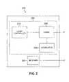
- FIG. 2is a schematic representation of an exemplary transponder in accordance with the present invention.
- FIG. 3shows an exemplary reconfigurable optical switch that may be employed in the present invention.
- FIG. 4shows an exemplary network node that provides protected services in the event of a fault.
- FIG. 5shows another network node that provides an additional degree of protection services in the event of a fault.
- FIG. 6shows a network node similar to that of FIG. 5 in which one of the optical switches is replaced with passive couplers.
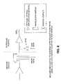
- FIG. 7shows a network node similar to that of FIG. 6 in which another of the optical switches is replaced with a splitter followed by tunable bandpass filters.
- FIG. 8shows yet another network node configuration.
- a WDM optical transmission systemwhich employs reconfigurable switching elements that can dynamically change the channel wavelength that is routed between any pair of input and output ports.
- the present inventionprovides a “plug and play” arrangement in which any transmitter can be connected to any input port of the switching element, after which the switching element is reconfigured so that its input ports are assigned to the operating wavelengths of the transmitters respectively connected to those ports, thus allowing the wavelengths to be properly routed through the switching element.
- reconfigurable optical elementscan dynamically change the path along which a given wavelength is routed to effectively reconstruct the topology of the network as necessary to accommodate a change in demand or to restore services around a network failure.
- reconfigurable optical elementsinclude optical Add/Drop Multiplexers (OADM) and Optical Cross-Connects (OXC).
- OADMsare used to separate or drop one or more wavelength components from a WDM signal, which is then directed onto a different path. In some cases the dropped wavelengths are directed onto a common fiber path and in other cases each dropped wavelength is directed onto its own fiber path.
- OXCsare more flexible devices than OADMs, which can redistribute in virtually any arrangement the components of multiple WDM input signals onto any number of output paths.
- current OXC'sgenerally employ optoelectronic regeneration at their network interfaces, thus requiring optical-to-electrical interfaces into and out of the cross-connect.
- Such an arrangementgives rise to a number of limitations, including a relatively high insertion loss because the optical signals must pass through three discrete components.
- the componentsare relatively expensive while still not providing a completely flexible switch that can transfer light between any two subsets of the ports.
- regeneratorsovercome the problem of insertion loss and effectively allow wavelength conversion of the signal as it traverses the switch fabric, they substantially add to the cost of an already expensive switch fabric because a regenerator is required for each and every wavelength that is used in the network.
- This referencediscloses an optical switching element in which each and every wavelength component can be directed from any given port to any other port without constraint. More specifically, unlike most optical switches, this switch is not limited to providing connections between a subset of input ports and a subset of output ports, or vice versa. Rather, this switch can also provide a connection between two ports within the same subset (either input or output). While the present invention may employ any of the aforementioned reconfigurable optical switches, the optical switch disclosed in U.S. patent application Ser. No. 09/691,812 will serve as an exemplary reconfigurable optical switch, and accordingly, additional details concerning this switch will be presented below.
- FIG. 1schematically depicts a bi-directional wavelength division multiplexed (WDM) optical communication system 10 according to one embodiment of the present invention.
- Optical communication system 10includes optical transmission paths 40 1 and 40 2 for transporting information in opposite directions, a first pair of optical switches 30 1 and 30 2 , which are typically co-located in a common node, a second pair of optical switches 32 1 , and 32 2 , which are also typically co-located in a common node, and a plurality of optical transponders 20 1 - 20 6 and 60 1 - 60 6 , e.g., transmitter/receiver pairs, respectively assigned to the first and second pair of optical switches 30 and 32 .
- WDMwavelength division multiplexed
- Each optical transponderemits and receives an information-bearing optical signal at an optical channel wavelength that differs from transmitter to transmitter.
- information-bearing optical signalrefers to an optical signal which has been coded with information, including, but not limited to, audio signals, video signals, and computer data.
- the WDM optical communication systems of the present inventioninclude N channels, where N is a whole number greater than or equal to 2. Exemplary values for N are 4, 8, and 16 optical channels. In the optical system of FIG. 1 , N is depicted as 6 for ease of illustration.
- WDM systemssuch as shown in FIG. 1 , which have a point-to-point configuration consisting of end terminals or nodes spaced from each other by one or more segments of optical fiber.
- WDM systemshaving a ring or loop configuration are currently being developed. Such systems typically include a plurality of nodes located along the ring. At least one optical add/drop element, associated with each node, is typically connected to the ring with optical connectors. The optical add/drop element permits both addition and extraction of channels to and from the ring.
- One of the nodestypically has a plurality of associated add/drop elements for transmitting and receiving a corresponding plurality of channels to/from other nodes along the ring.
- a hub or central office nodetypically has a plurality of associated add/drop elements for transmitting and receiving a corresponding plurality of channels to/from other nodes along the ring.
- the present inventionis equally applicable to other network topologies in addition to rings such as a mesh topology.
- FIG. 2shows an exemplary transponder 200 that may be employed as optical transponders 20 1 - 20 8 and 60 1 - 60 8 seen in FIG. 1 .
- Transponder 200includes a transmitter 250 and receiver 240 .
- the receiver 240generally detects the optical signal and converts it to an electrical signal, typically through the use of a photodiode device.
- the transmitter 250generally includes a laser 220 , such as a DFB semiconductor laser, a laser controller 210 , and a modulator 230 for creation of an information-bearing optical signal.
- the transmitter laser 220is a DFB semiconductor diode laser, generally comprising one or more III-V semiconductor materials, commercially available from a wide variety of suppliers.
- the laseroutputs an optical carrier signal at a particular wavelength assigned to its channel.
- the laser controller 210provides the required laser bias current as well as thermal control of the laser 220 . Using thermal control, the precise operating wavelength of the laser is maintained, typically to within a one-angstrom bandwidth or less.
- the optical transmitter 250typically includes a modulator 230 for imparting information to the optical carrier signal.
- An exemplary modulatoris an external modulator, such as a Mach-Zehnder modulator, employing a waveguiding medium whose refractive index changes according to the applied electrical field, i.e., a material exhibiting an electro-optic effect.
- a Mach-Zehnder modulatoremploying a waveguiding medium whose refractive index changes according to the applied electrical field, i.e., a material exhibiting an electro-optic effect.
- two optical interferometer pathsare provided in the Mach-Zehnder configuration.
- An incoming optical carrier signalis split between the two optical paths.
- At least one path of the interferometeris phase modulated.
- optical carrier signalcan alternatively be directly modulated for some system applications. It is noted that while the above-described transmitters are exemplary, any transmitting elements capable of producing optical signals for use in an optical communication system can be employed in the WDM systems of the present invention.
- the wavelengths emitted by the optical transmittersare selected to be within the 1500 nanometer range, the range in which the minimum signal attenuation occurs for silica-based fibers. More particularly, the wavelengths emitted by the optical transmitters are selected to be in the range from 1530 to 1560 nanometers. However, other wavelengths, such as those in the 1300-1500 nm range and the 1600 nm range, can also be employed in the WDM systems of the present invention.
- Optical transmittersmay operate at a single fixed wavelength or they may be tunable to operate and any wavelength within a predefined range of wavelengths.
- Each information-bearing optical signal produced by an optical transmitterconstitutes a channel in optical system 10 .
- each channelis generally associated with a unique wavelength.
- six optical transponders 20 1 - 20 6are provided to create a six-channel wavelength division multiplexed optical communication system along transmission path 40 1 and six optical transponders 60 1 - 60 6 are provided to create a six-channel wavelength division multiplexed optical communication system along transmission path 40 2 .
- the optical transmitters located within transponders 20 1 - 20 6operate at channel wavelengths of ⁇ 1 - ⁇ 6 , respectively.
- optical signal channelsare output from transponders 20 1 - 20 6 and are brought together in optical switch 30 1 for conveyance to optical waveguide 40 1 via output port 26 1 in the form of a multiplexed optical signal.
- Optical switch 30 1has six input ports that are optically coupled to the six transponders 20 1 - 20 6 through optical waveguides 22 1 - 22 6 .
- the optical transmitters located within transponders 60 1 - 60 6also operate at channel wavelengths of ⁇ 1 - ⁇ 6 respectively.
- These optical signal channelsare output from transponders 60 1 - 60 6 and are brought together in optical switch 32 2 for conveyance to optical waveguide 40 2 via output port 26 2 .
- Optical transmission path 40 1is typically an optical waveguide and is the principal transmission medium for the optical communication system.
- optical waveguideis generally selected from single-mode optical
- any optical waveguiding medium which is capable of transporting multiple optical wavelengthscan be employed as waveguide 40 1 in optical system 10 .
- optical switch 32 2Similar to optical switch 30 1 , optical switch 32 2 provides a multiplexed optical signal along optical transmission path 40 2 . Following transmission and amplification of the multiplexed optical signals along waveguides 40 1 and 40 2 , each channel must be demultiplexed and routed to the receiver located in the transponder designated for the particular optical signal channel.
- optical amplifiers 50are interposed along optical transmission paths 40 1 and 40 2 .
- Optical amplifiers 50are selected from any device which directly increases the strength of plural optical signals without the need for optical-to-electrical conversion.
- optical amplifiers 50are selected from optical waveguides doped with a material which can produce laser action in the waveguide. Such materials include rare earth dopants such as erbium, neodymium, praseodymium, ytterbium, or mixtures thereof.
- Pumping of the doped waveguide at a specific pump wavelengthcauses population inversion among the electron energy levels of the dopant, producing optical amplification of the wavelength division multiplexed optical signals.
- a wavelength band between approximately 1500 nm and approximately 1630 nmprovides gain to optical signals when the doped fiber is pumped.
- optical switches 30 1 - 30 2 and 32 1 - 32 2are generally based on multiplexers and demultiplexers that are fixed wavelength-dependent elements in which a given wavelength must be pre-assigned to a particular pair of input/output ports. As a result, each port must be connected to a different transponder that incorporates a transmitter operating at the wavelength associated with that port.
- DWDM systemsare implemented with an ever-increasing number of channels, installation of the transmitters becomes an increasingly complex task that is time-consuming and prone to error.
- this taskis simplified by employing flexible optical switches instead of fixed-wavelength dependent switching elements.
- Such optical switchesare reconfigurable elements that can dynamically change the channel wavelength that is assigned to its input and output ports.
- the optical switch 300comprises an optically transparent substrate 308 , a plurality of dielectric thin film filters 301 , 302 , 303 , and 304 , a plurality of collimating lens pairs 321 , 322 , 323 , and 324 , a plurality of tiltable mirrors 315 , 316 , 317 , and 318 and a plurality of output ports 340 1 , 340 2 , . . . 340 n .
- a first filter arrayis composed of thin film filters 301 and 303 and a second filter array is composed of thin film filters 302 and 304 .
- Each thin film filteralong with its associated collimating lens pair and tiltable mirror effectively forms a narrow band, free space switch, i.e. a switch that routes individual wavelength components along different paths.
- the tiltable mirrorsare micro mirrors such as the MEMS (microelectromechanical systems) mirrors. Alternatively, other mechanisms may be employed to control the position of the mirrors, such as piezoelectric actuators, for example.
- a WDM optical signalcomposed of different wavelengths ⁇ 1 , ⁇ 2 , ⁇ 3 and ⁇ 4 is directed from the optical input port 340 to a collimator lens 314 .
- the WDM signaltraverses substrate 308 and is received by thin film filter 301 .
- the optical component with wavelength ⁇ 1is transmitted through the thin film filter 301 , while the other wavelength components are reflected and directed to thin film filter 302 via substrate 308 .
- the wavelength component ⁇ 1which is transmitted through the thin film filter 301 , is converged by the collimating lens 321 onto the tiltable mirror 315 .
- Tiltable mirror 315is positioned so that wavelength component ⁇ 1 is reflected from the mirror to a selected one of the output ports 340 1 - 340 n via thin film filters 302 - 304 , which all reflect wavelength component ⁇ 1 .
- the particular output port that is selected to receive the wavelength componentwill determine the particular orientation of the mirror 315 .
- switching elements 30 1 - 30 2 and 32 1 - 32 2are reconfigurable, then when installing a set of transmitters or transponders that have been pre-selected to operate at the various channel wavelengths of the switch, the field technician can, in principle, connect any transmitter or transponder to any of the switch input ports.
- the switching elementscan be internally reconfigured so that their input ports correspond to the operating wavelengths of the transponders to which the respective input ports are connected. That is, the switching elements are configured to conform to the sequential arrangement of the transponders rather than requiring the sequential arrangement of the transponders to conform to the configuration of the switching element. In this way a “plug and play” approach is achieved in which the technician is able to connect any transponder to any input port of the optical switches.
- each transponderis associated with a memory module that identifies the operating wavelength of its transmitter.
- the memory modules incorporated into the transpondersmay be read only (ROM) or a rewritable memory such as RAM.
- the memory modulemay be an EPROM that stores the operating wavelength or wavelengths of the transmitter located in the transponder.
- the optical switchincorporates a controller that reads the memory module when the transponder is received by one of its input ports.
- the memory module and controllermay be replaced by alternative identification mechanisms or even eliminated. For example, in some cases the technician may simply manually input an identification number such as a serial number or a model number into the switch controller.
- the switchRegardless of the mechanism by which the switch obtains the information it needs to properly configure its input ports so that they are assigned the same wavelengths as the transponders connected to those ports, the switch in turn provides this information to software resident in the transmission network.
- This softwaremay reside in a network management element that operates at the highest level of network control.
- the softwarecan compare the wavelengths that are available on the transmission path with the operating wavelengths of the transponders that have been installed in the switch. If there is a match, the software can establish the connection at the appropriate wavelength. This process is much less prone to error because it is controlled by software and is not dependent on manual provisioning by a technician.
- the network softwarecan alert the technician or the network operations center so that an unsuitable transponder can be replaced with an appropriate transponder operating at an appropriate wavelength.
- a transpondermay be unsuitable for a variety of reasons, including, for example, because it operates at the wrong wavelength, transmission rate, or in the wrong transmission format.
- a transmitter that has been installed in a switchmay also be unsuitable because of a hardware failure or because of technician error during the installation process.
- the aforementioned inventive plug and play arrangement for installing transpondersis applicable not only to WDM communication systems of the type depicted in FIG. 1 , but also to communication systems that employ more complex arrangements of transponders and switches for the purpose of providing varying degrees of redundancy to ensure that service will be maintained in the event of a failure in a component or the transmission path. Redundancy is typically provided in such systems for two failure scenarios. One is to provide protection from a transponder failure by providing a duplicate backup transponder on both ends of the service to transmit information should either of the first transponders fail.
- the secondprotects against a fiber cut by providing two diverse paths (fibers) over which a signal can travel between the source and destination, where the signal source may come from two transponders, or be switched between paths from a single transponder.
- the transponder failureimpacts one wavelength (service) and occurs more frequently than a fiber cut, which will impact all the wavelengths in the fiber. Therefore since the network impact in these scenarios is different, the protection requirement for either of these options will depend on the type of services in the optical layer, and whether such services are protected at other layers in the network (i.e. via transmission protocol).
- the most reliable optical protection from a network equipment perspectiveis using a source pair of transponders that are simultaneously routed via different paths to a destination transponder pair.
- the signalsare routed between each transponder via an electrical backplane, where upon failure of the signals along a working path the transponders will change the signal source to the protection path, thereby ensuring communication after a failure.
- the inventive plug and play arrangementadvantageously facilitates the implementation of this type of redundancy because the protection transponders can always be inserted in adjacent slots, resulting in a less challenging backplane design because the degradation of high frequency electrical signals is reduced by minimizing the backplane interconnection lengths in this manner.
- this plug and play arrangementmay be used by the communication system to automatically restore service when a failure does arise without the need for manual reconfiguration.
- FIGS. 4-5which illustrate exemplary nodes incorporating such protection schemes, will be presented after the following discussion of various conventional protection schemes
- a number of different well-known protection techniquesmay be used in connection with networks that employ nodes that incorporate backup transponders.
- a dedicated protection techniquecan be used in which two copies of the same information-bearing signal are transmitted in opposite directions around the ring. While both signals can be transmitted at the same or different wavelengths, it generally will be more efficient to use the same wavelength because this fully utilizes the ring's capacity at that wavelength while placing no restrictions on the use of other wavelengths because of wavelength blocking.
- a dedicated protection techniqueis an extremely reliable and rapidly responsive form of protection
- a disadvantage of dedicated protectionis that it is extremely rare that the backup signal will ever be used, thus making it an inefficient and hence expensive form of protection.
- shared protectionis typically implemented by reserving a single channel as a back-up channel to protect multiple channels traveling different paths on another wavelength.
- a disadvantage of shared protectionis that restoration generally takes more time after a failure and requires more network signaling than dedicated protection because the backup channel is not already transmitting the signal at the time of failure. Since shared protection requires the backup transmitter and appropriate switches to be activated, it also has a greater probability of not restoring service because of a component failure during the restoration process. Because dedicated and shared protection schemes offer different advantages and disadvantages, different customers may prefer one over the other and thus service providers might ideally want to offer both schemes on the same network and even from the same transponder slot, if this could be arranged with minimal difficulty.
- one or more of the transponders 60 1 - 60 6may serve as backup for the remaining transponders 60 1 - 60 6 .
- This arrangementcan be called 1:N protection, where N working transponders are protected with 1 backup transponder.
- 1:N protectionin more advanced optical networks is that the entire path through a wavelength-routed network must be reconfigured during the transition to the backup transponder unless the backup transponder can transmit at the same wavelength as the primary transponder it is replacing. Such a path reconfiguration is extremely undesirable because it requires network-wide communication and reconfiguration, which leads to an additional delay in service restoration.
- the backup transponderdoes not employ the same wavelength as the failed transponder, further inefficiencies arise because one or more additional wavelengths must be reserved along all potentially protected paths, thereby setting aside bandwidth which otherwise could be used for revenue generating services. For these reasons it would advantageous to protect N transponders operating at different wavelengths with a single backup transponder that is tunable so that its output can emit the same wavelength as any of the N primary transponders, should any of them fail.
- a reconfigurable switch with an 1:N protection schemeis highly desirable because the switch controls the coupling of both the working and protection transponders to the transmission system, which means that the switch can prevent the protection transponder from transmitting through the system until a protection state is activated.
- the switchcan preferably only allow the appropriate wavelength to be coupled into the transmission system to replace the failed transponder, and this coupling can be provided at an insertion loss that is similar to original transponder.
- This functionalityenables the working and protection transponders to offer similar optical transmission capabilities when their transmitters have the same output power, which means there could be only one code of transponder for either application. It also controls from the system perspective which transponder receives a given incoming wavelength.
- This arrangementisolates the remaining transponders from any errant power output arising from the working and/or protection transponders that participate in providing protection. Finally, it also allows all protection events and actions to be isolated to the individual node in which the transponder fails, which reduces the time needed to restore service and simplifies the controlling software needed to provide the restoration.
- a 1:N protection schemeas described above only protects against a transponder failure and not a fiber cut. That is, if all N outputs are traveling on a single fiber and the fiber is cut, all N services will be disconnected. However, it should also be noted that transponder failures generally occur much more frequently that fiber cuts, and therefore the 1:N protection scheme is a suitable solution for many applications, even without reserving bandwidth for a fiber cut. If the advantages of 1:N protection are desired while protecting for a fiber cut, a hybrid protection scheme could be employed with the present invention using 1:N transponder protection and shared protection against a fiber cut.
- the shared protectionwould be implemented with a single transponder having a tunable wavelength output that circumvents fiber cuts by optically switching between two paths. Failure of the transponder would also be protected via conventional 1:N protection as described above, using a different wavelength tunable transponder.
- This form of protectionwould eliminate both the inefficiency of protection fiber paths that are rarely used, and also would eliminate the inefficiency from the need to require many backup transponders that are seldom used.
- the disadvantage of this approachwould be a complex, longer protection switching time to configure all the switches and tunable transponders, and an inability to protect against multiple transponder failures that are sharing a single protection transponder.
- FIG. 4shows a node that includes two sets of transponders 410 and 412 .
- Each set 410 and 412includes a series of transponders operational at the different wavelengths that correspond to the various channel wavelengths employed in the transmission system.
- Transponders 410receive signal wavelengths from transmission path 400 1 , via switch 414 and transmit signal wavelengths on transmission path 400 2 via switch 416 while transponders 412 receive signal wavelengths from transmission path 400 2 via switch 416 and transmit signal wavelengths on transmission path 400 1 via switch 414 .
- transponder sets 410 and 412instead of a single set of transponders, a degree of redundancy is provided to ensure that service will be maintained if, for example, a fiber cut occurs at a single point in either transmission path 400 1 or 400 2 .
- a fiber cut at point 420 on path 400 1will disrupt service provided by transponders 410 but not transponders 412 .
- transponders 412can be used to maintain service.
- a fiber cut in both transmission paths 400 1 and 400 2will disrupt service provided by both sets of transponders 410 and 412 .
- the configuration shown in FIG. 4provides relatively high reliability because it is unlikely that there would be a simultaneous failure at multiple points in the transmission paths. Other types of failures, however, will cause all service to be interrupted. For example, should a failure occur in either of the switches 414 and 416 , service provided by both sets of transponder sets 410 and 412 will be disrupted.
- FIG. 5shows another node configuration that provides an additional degree of protection relative to the configuration shown in FIG. 4 .
- the node in FIG. 5employs four switches 514 , 516 , 518 and 520 .
- the transpondersare arranged in transponder pairs 522 - 527 located in adjacent slots. The individual transponders in each pair can serve as backup for the other in case of a failure. Similar to the configuration in FIG. 4 , the transponders in each pair communicate with different switches.
- transponder 522 1receives and transmits via switches 514 and 516 , respectively, while transponder 522 2 receives and transmits via switches 520 and 518 , respectively. Since the two transponders in each pair transmit and receive on completely different switches, a failure in one switch need not disrupt service because the service provided by the impacted switch can be provided by the other transponder in the adjacent slot.
- the present inventionoffers the requisite degree of flexibility to quickly and easily reconfigure a service to support a variety of different protection schemes such as the aforementioned dedicated, shared, or 1:N protection schemes or even other protection schemes such as Dual Ring Interworking (DRI) for example, which uses the Drop and Continue feature that is discussed later in connection with FIG. 8 to split a signal in the node so that it can be dropped at multiple locations for interconnection to network
- DRIDual Ring Interworking
- the network softwarecan provision the switches for either a dedicated or shared protection scheme, eliminating the need for a technician to manually reconfigure the network.
- transponder 522 2incorporates a tunable transmitter
- a dedicated protection channelmay even be offered at the same wavelength as the in-service channel.
- FIG. 5One disadvantage of the node configuration shown in FIG. 5 is that it is relatively expensive to implement because it requires four optical switches.
- a cost savingsmay be obtained by replacing one or both switches 518 and 516 , which serve as add switches for adding wavelengths to the transmission system, with an arrangement of passive optical combiners such as couplers shown in FIG. 5 , or alternatively, with 1 ⁇ N star couplers for larger port count implementations.
- Each transpondermay be connected to a passive coupler that in turn couples the wavelength to a series of one or more additional passive couplers that couple the resulting WDM signal to the transmission system.
- the add switch 518 of FIG. 5is replaced with an arrangement of passive couplers 618 . It is to be understood that FIG.
- FIG. 7shows another embodiment of the invention in which the drop switch 514 of FIG. 5 is replaced with a passive splitter 714 followed by tunable bandpass filters 715 , each of which couple one of the dropped wavelengths to the appropriate transponder (not shown in FIG. 7 ).
- This all-passive configurationfurther reduces the cost of the node, although it may require additional optical amplifiers to accommodate the losses imparted by the passive splitters.
- One characteristic of this all-passive configurationis that not all the power in a dropped channel is in fact entirely dropped. Rather, because no filtering is performed, a portion of the dropped channel exits the node and continues along the transmission path.
- This characteristiccan be advantageous when there is a need to create multiple copies of a signal or to broadcast a signal.
- this characteristicalso prevents wavelengths from being reused because crosstalk would arise between the portion of the dropped channel remaining on the transmission path and the added channel located at the same wavelength.
- the primary disadvantage of the configuration shown in FIG. 7is that it is very bandwidth inefficient and thus unattractive unless the number of available wavelengths is greater than the total number of connections to be used in the network.
- FIG. 8shows another node that can perform the drop and continue functionality of the node in FIG. 7 , but which also allows wavelengths to be reused.
- switches 816 and 818serve as drop and add switches, respectively (see the discussion of switches 514 and 518 in FIG. 5 ).
- a passive coupler 820 preceding switch 816splits the WDM signal traveling on transmission path 800 1 as it enters the node.
- One output of the passive coupler 820is coupled to optical switch 816 and the other output of the passive coupler 820 is coupled to an input of switch 818 .
- Switch 818can therefore remove any wavelengths dropped by switch 816 that were not designated for multicast transmission.
- the capability to transmit multicastcan be used in the communication network to broadcast to multiple locations from a single transponder, or to create a dual-homing diverse path for network protection of an optical signal.
- Dual Ring Interworkingis an example of dual homing, wherein the diverse routing between two rings occurs at separate node-pairs.
- the ability to reuse wavelengths within an optical network such as in FIG. 8is one key means to improve overall network efficiency. Because there is an effective network cost to provide the facilities to transport a given wavelength, if that wavelength is used for multiple transport links within a ring or network, the cost of the wavelength is shared. Current technology requires filtering or removal of the dropped wavelength on the order of 99.9% if the wavelength is to be reused. This wavelength-dependent filtering is preferably performed while adding minimal loss to the adjacent wavelengths, which are typically only separated by 1 nm or less in current WDM systems. Technologies that are unable to meet this demanding filtering requirement with the wavelength filtering used in the drop path may also employ additional filtering to achieve the level required to reuse the same wavelength at other points in the network.
- the element providing this additional filteringis sometimes referred to as a clean up filter or a blocking filter.
- the blocking filtermay be a distinct filter element or it may be integrated with the drop element itself.
- An example of a blocking filter with the latter configurationis shown, for example, in Duck et al, U.S. Pat. No. 5,920,411.
- the drop and continue configuration shown in FIG. 8is one specific example of a blocking switch, where the passive coupler 820 does not block the wavelengths that will be dropped, and thus the second switch 818 must block the dropped wavelengths as well as adding wavelengths to the network.
- the transpondersinclude tunable lasers.
- thisis accomplished with a multiplexer having ports that generally each offer low insertion loss at a single wavelength.
- the flexibility of the tunable laseris restricted by the multiplexer so that the laser can only be used at the single wavelength.
- One way to overcome this problemis by using a passive coupler that couples all wavelengths with the same insertion loss. Of course, this solution comes at the expense of higher insertion loss.
- the present inventionprovides an alternative solution to this problem because the reconfigurable switch can serve as a low loss reconfigurable multiplexer.
- any of the wavelengths generated by the lasercan be multiplexed onto the data stream with low loss.
- This solutionis particularly advantageous because it enables systems to operate in accordance with the same engineering rules for both fixed and tunable lasers, which is important in hybrid systems using fixed and tunable transponders.
Landscapes
- Engineering & Computer Science (AREA)
- Physics & Mathematics (AREA)
- Computer Networks & Wireless Communication (AREA)
- Signal Processing (AREA)
- General Physics & Mathematics (AREA)
- Optics & Photonics (AREA)
- Electromagnetism (AREA)
- Computing Systems (AREA)
- Optical Communication System (AREA)
- Use Of Switch Circuits For Exchanges And Methods Of Control Of Multiplex Exchanges (AREA)
- Mechanical Light Control Or Optical Switches (AREA)
Abstract
Description
Claims (19)
Priority Applications (2)
| Application Number | Priority Date | Filing Date | Title |
|---|---|---|---|
| US10/099,890US7620323B2 (en) | 2001-03-16 | 2002-03-15 | Method and apparatus for interconnecting a plurality of optical transducers with a wavelength division multiplexed optical switch |
| US12/620,512US20100098406A1 (en) | 2001-03-16 | 2009-11-17 | Method and apparatus for interconnecting a plurality of optical transducers with a wavelength division multiplexed optical switch |
Applications Claiming Priority (2)
| Application Number | Priority Date | Filing Date | Title |
|---|---|---|---|
| US27631001P | 2001-03-16 | 2001-03-16 | |
| US10/099,890US7620323B2 (en) | 2001-03-16 | 2002-03-15 | Method and apparatus for interconnecting a plurality of optical transducers with a wavelength division multiplexed optical switch |
Related Child Applications (1)
| Application Number | Title | Priority Date | Filing Date |
|---|---|---|---|
| US12/620,512ContinuationUS20100098406A1 (en) | 2001-03-16 | 2009-11-17 | Method and apparatus for interconnecting a plurality of optical transducers with a wavelength division multiplexed optical switch |
Publications (2)
| Publication Number | Publication Date |
|---|---|
| US20020145779A1 US20020145779A1 (en) | 2002-10-10 |
| US7620323B2true US7620323B2 (en) | 2009-11-17 |
Family
ID=23056135
Family Applications (9)
| Application Number | Title | Priority Date | Filing Date |
|---|---|---|---|
| US10/099,891Expired - Fee RelatedUS7676157B2 (en) | 2001-03-16 | 2002-03-15 | Method and apparatus for providing gain equalization to an optical signal in an optical communication system |
| US10/098,746Expired - LifetimeUS6614953B2 (en) | 2001-03-16 | 2002-03-15 | Modular all-optical cross-connect |
| US10/099,888AbandonedUS20020145782A1 (en) | 2001-03-16 | 2002-03-15 | Method and apparatus for transferring WDM signals between different wavelength division multiplexed optical communications systems in an optically transparent manner |
| US10/099,890Expired - Fee RelatedUS7620323B2 (en) | 2001-03-16 | 2002-03-15 | Method and apparatus for interconnecting a plurality of optical transducers with a wavelength division multiplexed optical switch |
| US10/632,670Expired - Fee RelatedUS7469080B2 (en) | 2001-03-16 | 2003-08-01 | Modular all-optical cross-connect |
| US12/259,946Expired - Fee RelatedUS9258628B2 (en) | 2001-03-16 | 2008-10-28 | Method and apparatus for transferring WDM signals between different wavelength division multiplexed optical communications systems in an optically transparent manner |
| US12/343,422Expired - Fee RelatedUS7738748B2 (en) | 2001-03-16 | 2008-12-23 | Modular all-optical cross-connect |
| US12/620,512AbandonedUS20100098406A1 (en) | 2001-03-16 | 2009-11-17 | Method and apparatus for interconnecting a plurality of optical transducers with a wavelength division multiplexed optical switch |
| US15/003,037AbandonedUS20160142172A1 (en) | 2001-03-16 | 2016-01-21 | Ring network including at least one subtending ring originating and terminating at a central-office node |
Family Applications Before (3)
| Application Number | Title | Priority Date | Filing Date |
|---|---|---|---|
| US10/099,891Expired - Fee RelatedUS7676157B2 (en) | 2001-03-16 | 2002-03-15 | Method and apparatus for providing gain equalization to an optical signal in an optical communication system |
| US10/098,746Expired - LifetimeUS6614953B2 (en) | 2001-03-16 | 2002-03-15 | Modular all-optical cross-connect |
| US10/099,888AbandonedUS20020145782A1 (en) | 2001-03-16 | 2002-03-15 | Method and apparatus for transferring WDM signals between different wavelength division multiplexed optical communications systems in an optically transparent manner |
Family Applications After (5)
| Application Number | Title | Priority Date | Filing Date |
|---|---|---|---|
| US10/632,670Expired - Fee RelatedUS7469080B2 (en) | 2001-03-16 | 2003-08-01 | Modular all-optical cross-connect |
| US12/259,946Expired - Fee RelatedUS9258628B2 (en) | 2001-03-16 | 2008-10-28 | Method and apparatus for transferring WDM signals between different wavelength division multiplexed optical communications systems in an optically transparent manner |
| US12/343,422Expired - Fee RelatedUS7738748B2 (en) | 2001-03-16 | 2008-12-23 | Modular all-optical cross-connect |
| US12/620,512AbandonedUS20100098406A1 (en) | 2001-03-16 | 2009-11-17 | Method and apparatus for interconnecting a plurality of optical transducers with a wavelength division multiplexed optical switch |
| US15/003,037AbandonedUS20160142172A1 (en) | 2001-03-16 | 2016-01-21 | Ring network including at least one subtending ring originating and terminating at a central-office node |
Country Status (8)
| Country | Link |
|---|---|
| US (9) | US7676157B2 (en) |
| EP (3) | EP1368924A4 (en) |
| JP (3) | JP2004536484A (en) |
| KR (5) | KR100993182B1 (en) |
| CN (4) | CN1596517A (en) |
| AU (2) | AU2002254262A1 (en) |
| CA (4) | CA2441343A1 (en) |
| WO (4) | WO2002075998A1 (en) |
Cited By (5)
| Publication number | Priority date | Publication date | Assignee | Title |
|---|---|---|---|---|
| US20090241123A1 (en)* | 2008-03-21 | 2009-09-24 | International Business Machines Corporation | Method, apparatus, and computer program product for scheduling work in a stream-oriented computer system with configurable networks |
| US20090238178A1 (en)* | 2008-03-21 | 2009-09-24 | International Business Machines Corporation | Method, system, and computer program product for implementing stream processing using a reconfigurable optical switch |
| US20100040053A1 (en)* | 2008-08-14 | 2010-02-18 | Dell Products, Lp | System and method for dynamic maintenance of fabric subsets in a network |
| WO2011133253A3 (en)* | 2010-04-21 | 2012-03-29 | Nec Laboratories America, Inc. | Roadm systems and methods of operation |
| US9429712B2 (en) | 2014-07-23 | 2016-08-30 | Ii-Vi Incorporated | Dual-ganged optical switch |
Families Citing this family (159)
| Publication number | Priority date | Publication date | Assignee | Title |
|---|---|---|---|---|
| US6721508B1 (en) | 1998-12-14 | 2004-04-13 | Tellabs Operations Inc. | Optical line terminal arrangement, apparatus and methods |
| US6618520B2 (en)* | 1999-11-09 | 2003-09-09 | Texas Instruments Incorporated | Micromirror optical switch |
| US6922530B1 (en) | 2000-04-06 | 2005-07-26 | Fujitsu Limited | Method and apparatus for optical channel switching in an optical add/drop multiplexer |
| US6633694B2 (en)* | 2000-09-29 | 2003-10-14 | Texas Instruments Incorporated | Micromirror optical switch |
| EP1368924A4 (en)* | 2001-03-16 | 2010-01-06 | Meriton Networks Us Inc | Method and apparatus for transferring wdm signals between different wdm communications systems in optically transparent manner |
| US6941071B2 (en)* | 2001-05-25 | 2005-09-06 | International Business Machines Corporation | Test method and apparatus for parallel optical transceivers using serial equipment |
| GB0121308D0 (en) | 2001-09-03 | 2001-10-24 | Thomas Swan & Company Ltd | Optical processing |
| JP3693020B2 (en)* | 2002-01-22 | 2005-09-07 | 日本電気株式会社 | Wavelength division multiplexing optical transmission apparatus and communication system using the apparatus |
| GB0203037D0 (en)* | 2002-02-08 | 2002-03-27 | Marconi Comm Ltd | Telecommunications networks |
| US20030174935A1 (en)* | 2002-03-14 | 2003-09-18 | Miller Samuel Lee | Channel balancer for WDM optical units |
| US7085242B2 (en)* | 2002-03-22 | 2006-08-01 | Telcordia Technologies, Inc. | Virtual IP topology reconfiguration migration |
| US7076163B2 (en)* | 2002-03-27 | 2006-07-11 | Fujitsu Limited | Method and system for testing during operation of an open ring optical network |
| US7231148B2 (en)* | 2002-03-28 | 2007-06-12 | Fujitsu Limited | Flexible open ring optical network and method |
| US7116905B2 (en)* | 2002-03-27 | 2006-10-03 | Fujitsu Limited | Method and system for control signaling in an open ring optical network |
| US7072584B1 (en)* | 2002-04-22 | 2006-07-04 | Atrica Israel Ltd. | Network hub employing 1:N optical protection |
| US7283739B2 (en)* | 2002-05-29 | 2007-10-16 | Fujitsu Limited | Multiple subnets in an optical ring network and method |
| US7283740B2 (en)* | 2002-05-29 | 2007-10-16 | Fujitsu Limited | Optical ring network with optical subnets and method |
| US7184663B2 (en) | 2002-05-29 | 2007-02-27 | Fujitsu Limited | Optical ring network with hub node and method |
| US7075712B2 (en) | 2002-05-30 | 2006-07-11 | Fujitsu Limited | Combining and distributing amplifiers for optical network and method |
| US7085496B2 (en) | 2002-05-30 | 2006-08-01 | Fujitsu Limited | Passive add/drop amplifier for optical networks and method |
| US6842562B2 (en)* | 2002-05-30 | 2005-01-11 | Fujitsu Network Communications, Inc. | Optical add/drop node and method |
| US7813601B2 (en)* | 2002-09-06 | 2010-10-12 | Texas Instruments Incorporated | Reconfigurable optical add/drop multiplexer |
| US20040052530A1 (en)* | 2002-09-17 | 2004-03-18 | Cechan Tian | Optical network with distributed sub-band rejections |
| WO2004028999A2 (en)* | 2002-09-23 | 2004-04-08 | Basf Aktiengesellschaft | Thin films of oxidic materials having a high dielectric constant |
| US7715713B1 (en)* | 2002-09-30 | 2010-05-11 | Meriton Networks Us Inc. | Method and apparatus for providing multiple optical channel protection switching mechanisms in optical rings |
| US7321729B2 (en)* | 2003-05-29 | 2008-01-22 | Fujitsu Limited | Optical ring network with selective signal regeneration and wavelength conversion |
| US20050019034A1 (en)* | 2003-07-25 | 2005-01-27 | Fujitsu Network Communications, Inc. | System and method for communicating optical traffic between ring networks |
| US7483636B2 (en)* | 2003-07-28 | 2009-01-27 | Fujitsu Limited | Optical network with sub-band rejection and bypass |
| US6885798B2 (en) | 2003-09-08 | 2005-04-26 | Adc Telecommunications, Inc. | Fiber optic cable and furcation module |
| DE10343615A1 (en)* | 2003-09-20 | 2005-04-14 | Marconi Communications Gmbh | Network node for an optical communications network |
| US20050095001A1 (en)* | 2003-10-29 | 2005-05-05 | Fujitsu Limited | Method and system for increasing network capacity in an optical network |
| US7483637B2 (en) | 2003-11-26 | 2009-01-27 | Fujitsu Limited | Optical ring network with optical subnets and method |
| US7570672B2 (en)* | 2004-02-02 | 2009-08-04 | Simplexgrinnell Lp | Fiber optic multiplex modem |
| US20050175346A1 (en)* | 2004-02-10 | 2005-08-11 | Fujitsu Limited | Upgraded flexible open ring optical network and method |
| US7369765B2 (en)* | 2004-02-26 | 2008-05-06 | Fujitsu Limited | Optical network with selective mode switching |
| US20050196169A1 (en)* | 2004-03-03 | 2005-09-08 | Fujitsu Limited | System and method for communicating traffic between optical rings |
| US20050232565A1 (en)* | 2004-04-16 | 2005-10-20 | Ross Heggestad | Normal through optical panel |
| US7257288B1 (en) | 2004-04-23 | 2007-08-14 | Nistica, Inc. | Tunable optical routing systems |
| US7408639B1 (en) | 2004-04-23 | 2008-08-05 | Nistica, Inc. | Tunable optical routing systems |
| US20050286896A1 (en)* | 2004-06-29 | 2005-12-29 | Fujitsu Limited | Hybrid optical ring network |
| US7450851B2 (en)* | 2004-08-27 | 2008-11-11 | Fujitsu Limited | System and method for modularly scalable architecture for optical networks |
| US7639677B2 (en)* | 2004-11-02 | 2009-12-29 | Electronics And Telecommunications Research Institute | Optical transponder having switching function |
| US7376322B2 (en) | 2004-11-03 | 2008-05-20 | Adc Telecommunications, Inc. | Fiber optic module and system including rear connectors |
| US7826743B2 (en)* | 2004-11-22 | 2010-11-02 | Fujitsu Limited | Optical ring network for extended broadcasting |
| JP4593267B2 (en)* | 2004-12-28 | 2010-12-08 | 富士通株式会社 | Optical node and optical add / drop multiplexer |
| US7120360B2 (en)* | 2005-01-06 | 2006-10-10 | Fujitsu Limited | System and method for protecting traffic in a hubbed optical ring network |
| US7570844B2 (en)* | 2005-01-18 | 2009-08-04 | Doron Handelman | Photonic integrated circuit device and elements thereof |
| US7412147B2 (en)* | 2005-03-15 | 2008-08-12 | Adc Telecommunications, Inc. | Normal through optical panel |
| US7376323B2 (en)* | 2005-05-25 | 2008-05-20 | Adc Telecommunications, Inc. | Fiber optic adapter module |
| US7400813B2 (en) | 2005-05-25 | 2008-07-15 | Adc Telecommunications, Inc. | Fiber optic splitter module |
| US7636507B2 (en) | 2005-06-17 | 2009-12-22 | Adc Telecommunications, Inc. | Compact blind mateable optical splitter |
| US8428461B2 (en)* | 2005-06-22 | 2013-04-23 | Tellabs Operations, Inc. | Apparatus for managing an optical signal |
| US7346254B2 (en)* | 2005-08-29 | 2008-03-18 | Adc Telecommunications, Inc. | Fiber optic splitter module with connector access |
| JP4673712B2 (en)* | 2005-09-28 | 2011-04-20 | 富士通株式会社 | Network configuration apparatus and network configuration method |
| US7526198B1 (en)* | 2005-11-30 | 2009-04-28 | At&T Corp. | Methods of restoration in an ultra-long haul optical network |
| US7639946B2 (en)* | 2006-01-06 | 2009-12-29 | Fujitsu Limited | Distribution node for an optical network |
| US7418181B2 (en) | 2006-02-13 | 2008-08-26 | Adc Telecommunications, Inc. | Fiber optic splitter module |
| KR100819035B1 (en) | 2006-09-29 | 2008-04-03 | 한국전자통신연구원 | Optical line splitter system, optical system based on optical line splitter system and optical network based on the system |
| KR100833501B1 (en)* | 2006-11-17 | 2008-05-29 | 한국전자통신연구원 | Multi-Dimensional Circuit Distribution System, Operation Method and Optical Communication Network Using the Same |
| US7391954B1 (en) | 2007-05-30 | 2008-06-24 | Corning Cable Systems Llc | Attenuated optical splitter module |
| US20080298743A1 (en)* | 2007-05-31 | 2008-12-04 | Konstantinos Saravanos | Microsplitter module for optical connectivity |
| US20080298748A1 (en)* | 2007-05-31 | 2008-12-04 | Terry Dean Cox | Direct-connect optical splitter module |
| CN101355430B (en)* | 2007-07-27 | 2012-02-29 | 华为技术有限公司 | Switch frames, cluster routers |
| US8798427B2 (en) | 2007-09-05 | 2014-08-05 | Corning Cable Systems Llc | Fiber optic terminal assembly |
| US7536075B2 (en) | 2007-10-22 | 2009-05-19 | Adc Telecommunications, Inc. | Wavelength division multiplexing module |
| US7885505B2 (en)* | 2007-10-22 | 2011-02-08 | Adc Telecommunications, Inc. | Wavelength division multiplexing module |
| EP2071377B1 (en)* | 2007-12-12 | 2012-04-18 | JDS Uniphase Corporation | Packaging a reconfigurable optical add-drop module |
| US8107816B2 (en) | 2008-01-29 | 2012-01-31 | Adc Telecommunications, Inc. | Wavelength division multiplexing module |
| US8045854B2 (en)* | 2008-02-07 | 2011-10-25 | Jds Uniphase Corporation | M×N wavelength selective optical switch |
| US8213794B2 (en)* | 2008-02-12 | 2012-07-03 | Nec Laboratories America, Inc. | Programmable optical network architecture |
| US8320759B2 (en)* | 2008-03-05 | 2012-11-27 | Tellabs Operations, Inc. | Methods and apparatus for reconfigurable add drop multiplexers |
| EP2335364A4 (en)* | 2008-08-08 | 2012-06-27 | Hewlett Packard Development Co | Methods and systems for implementing high-radix switch topologies on relatively lower-radix switch physical networks |
| US8774631B2 (en)* | 2008-08-20 | 2014-07-08 | Telefonaktiebolaget L M Ericsson (Publ) | Switch node |
| CN102209921B (en) | 2008-10-09 | 2015-11-25 | 康宁光缆系统有限公司 | There is the fibre-optic terminus supported from the adapter panel of the input and output optical fiber of optical splitters |
| US8879882B2 (en) | 2008-10-27 | 2014-11-04 | Corning Cable Systems Llc | Variably configurable and modular local convergence point |
| US8396366B2 (en)* | 2008-11-10 | 2013-03-12 | Cisco Technology, Inc. | Optical safety implementation in protection switching modules |
| CN102282495B (en)* | 2009-01-15 | 2015-04-22 | Adc电信公司 | Fiber optic module, chassis and adapter |
| US8218969B2 (en)* | 2009-03-18 | 2012-07-10 | Cisco Technology, Inc. | OFDM transponder interface with variable bit transfer rate in optical communications systems |
| EP2237091A1 (en) | 2009-03-31 | 2010-10-06 | Corning Cable Systems LLC | Removably mountable fiber optic terminal |
| US8467651B2 (en) | 2009-09-30 | 2013-06-18 | Ccs Technology Inc. | Fiber optic terminals configured to dispose a fiber optic connection panel(s) within an optical fiber perimeter and related methods |
| US9547144B2 (en) | 2010-03-16 | 2017-01-17 | Corning Optical Communications LLC | Fiber optic distribution network for multiple dwelling units |
| US8792767B2 (en) | 2010-04-16 | 2014-07-29 | Ccs Technology, Inc. | Distribution device |
| US8412042B2 (en)* | 2010-04-21 | 2013-04-02 | Cisco Technology, Inc. | Innovative architecture for fully non blocking service aggregation without O-E-O conversion in a DWDM multiring interconnection node |
| US9239442B2 (en) | 2010-04-27 | 2016-01-19 | Adc Communications (Shanghai) Co., Ltd. | Fiber optic module and chassis |
| US8300995B2 (en) | 2010-06-30 | 2012-10-30 | Jds Uniphase Corporation | M X N WSS with reduced optics size |
| US8553531B2 (en)* | 2010-08-03 | 2013-10-08 | Fujitsu Limited | Method and system for implementing network element-level redundancy |
| US8547828B2 (en)* | 2010-08-03 | 2013-10-01 | Fujitsu Limited | Method and system for implementing network element-level redundancy |
| JP5609463B2 (en)* | 2010-09-14 | 2014-10-22 | 富士通株式会社 | Transmission device, control device, and signal line misconnection detection method |
| JP5617503B2 (en)* | 2010-09-30 | 2014-11-05 | 富士通株式会社 | Optical network repeater |
| WO2012054454A2 (en) | 2010-10-19 | 2012-04-26 | Corning Cable Systems Llc | Transition box for multiple dwelling unit fiber optic distribution network |
| US9182563B2 (en) | 2011-03-31 | 2015-11-10 | Adc Telecommunications, Inc. | Adapter plate for fiber optic module |
| US8768167B2 (en) | 2011-04-29 | 2014-07-01 | Telcordia Technologies, Inc. | System and method for automated provisioning of services using single step routing and wavelength assignment algorithm in DWDM networks |
| US8842947B2 (en)* | 2011-06-03 | 2014-09-23 | Futurewei Technologies, Inc. | Method and apparatus for colorless add |
| WO2013033890A1 (en) | 2011-09-06 | 2013-03-14 | Adc Telecommunications, Inc. | Adapter for fiber optic module |
| EP2582152B1 (en)* | 2011-10-12 | 2018-08-29 | ADVA Optical Networking SE | Remote node and network architecture and data transmission method for a fiber-optic network, especially for low bit-rate data transmission |
| US9219546B2 (en) | 2011-12-12 | 2015-12-22 | Corning Optical Communications LLC | Extremely high frequency (EHF) distributed antenna systems, and related components and methods |
| CN102572621A (en)* | 2012-02-02 | 2012-07-11 | 中兴通讯股份有限公司 | Optical module and wavelength division multiplexing system |
| US10110307B2 (en) | 2012-03-02 | 2018-10-23 | Corning Optical Communications LLC | Optical network units (ONUs) for high bandwidth connectivity, and related components and methods |
| US8995832B2 (en)* | 2012-04-02 | 2015-03-31 | Nec Laboratories America, Inc. | Transponder Aggregator-based optical loopback in a MD-ROADM |
| WO2013162567A1 (en) | 2012-04-26 | 2013-10-31 | Hewlett-Packard Development Company, L.P. | Optical slab |
| EP2859676B1 (en) | 2012-05-04 | 2024-01-31 | Deutsche Telekom AG | Method and device for constructing and operating a modular, highly scalable, very simple, cost-efficient and sustainable transparent optically-routed network for network capacities of greater than 1 petabit(s) |
| US9004778B2 (en) | 2012-06-29 | 2015-04-14 | Corning Cable Systems Llc | Indexable optical fiber connectors and optical fiber connector arrays |
| EP2860885B1 (en)* | 2012-07-02 | 2019-05-08 | Nec Corporation | Optical branching unit and optical branching method |
| GB2504970A (en) | 2012-08-15 | 2014-02-19 | Swan Thomas & Co Ltd | Optical device and methods to reduce cross-talk |
| US9274299B2 (en) | 2012-08-29 | 2016-03-01 | International Business Machines Corporation | Modular optical backplane and enclosure |
| US9049500B2 (en) | 2012-08-31 | 2015-06-02 | Corning Cable Systems Llc | Fiber optic terminals, systems, and methods for network service management |
| US8768116B2 (en)* | 2012-09-28 | 2014-07-01 | Avago Technologies General Ip (Singapore) Pte. Ltd. | Optical cross-connect assembly and method |
| US8909019B2 (en) | 2012-10-11 | 2014-12-09 | Ccs Technology, Inc. | System comprising a plurality of distribution devices and distribution device |
| US9621967B2 (en)* | 2012-11-26 | 2017-04-11 | Viscore Technologies | Methods and systems for passive optical switching |
| ES1141660Y (en) | 2012-12-19 | 2015-10-14 | Tyco Electronics Raychem Bvba | Distribution device with incrementally added dividers |
| US9054955B2 (en) | 2012-12-30 | 2015-06-09 | Doron Handelman | Apparatus and methods for enabling recovery from failures in optical networks |
| FR3002393B1 (en)* | 2013-02-15 | 2016-06-24 | Thales Sa | INFORMATION TRANSMISSION ARCHITECTURE, IN PARTICULAR FOR APPLICATION TO AIRCRAFT AVIONICS |
| FR3002394B1 (en) | 2013-02-15 | 2015-03-27 | Thales Sa | ARCHITECTURE FOR TRANSMITTING INFORMATION WITH A BRIDGE, IN PARTICULAR FOR APPLICATION TO THE AIRCRAFT |
| US10036396B2 (en) | 2013-03-08 | 2018-07-31 | Coriant Operations, Inc. | Field configurable fan operational profiles |
| US9497519B2 (en)* | 2013-03-18 | 2016-11-15 | Oplink Communications, Inc. | Twin multicast switch |
| CN104238025B (en)* | 2013-06-21 | 2017-12-29 | 华为技术有限公司 | light path processing method and device |
| US10185691B2 (en)* | 2013-07-30 | 2019-01-22 | Hewlett Packard Enterprise Development Lp | Two-dimensional torus topology |
| US9819436B2 (en) | 2013-08-26 | 2017-11-14 | Coriant Operations, Inc. | Intranodal ROADM fiber management apparatuses, systems, and methods |
| US9344187B2 (en)* | 2013-09-17 | 2016-05-17 | Doron Handelman | Apparatus and methods for enabling recovery in optical networks |
| WO2015126472A2 (en) | 2013-11-11 | 2015-08-27 | Adc Telecommunications, Inc. | Telecommunications module |
| CN105122681A (en) | 2013-12-31 | 2015-12-02 | 华为技术有限公司 | Optical transmitter, transmission method, optical receiver and reception method |
| WO2015112169A1 (en)* | 2014-01-25 | 2015-07-30 | Hewlett-Packard Development Company, L.P. | Bidirectional optical multiplexing employing a high contrast grating |
| US9699074B2 (en)* | 2014-04-10 | 2017-07-04 | Fujitsu Limited | Efficient utilization of transceivers for shared restoration in flexible grid optical networks |
| AU2015276109B2 (en) | 2014-06-17 | 2020-11-19 | Adc Czech Republic, S.R.O. | Cable distribution system |
| WO2015200321A1 (en) | 2014-06-23 | 2015-12-30 | Adc Telecommunications, Inc. | Fiber cable fan-out assembly and method |
| US10243661B2 (en) | 2014-08-15 | 2019-03-26 | Hewlett Packard Enterprise Development Lp | Optical mode matching |
| WO2016037262A1 (en)* | 2014-09-09 | 2016-03-17 | Viscore Technologies Inc. | Low latency optically distributed dynamic optical interconnection networks |
| US10054753B2 (en) | 2014-10-27 | 2018-08-21 | Commscope Technologies Llc | Fiber optic cable with flexible conduit |
| WO2016099531A1 (en)* | 2014-12-19 | 2016-06-23 | Hewlett Packard Enterprise Development Lp | Bonded filter substrates |
| JP2016161802A (en)* | 2015-03-03 | 2016-09-05 | 富士通株式会社 | Variable optical attenuator and optical module |
| AU2015207954C1 (en) | 2015-07-31 | 2022-05-05 | Adc Communications (Australia) Pty Limited | Cable breakout assembly |
| WO2017034931A1 (en) | 2015-08-21 | 2017-03-02 | Commscope Technologies Llc | Telecommunications module |
| US10606009B2 (en) | 2015-12-01 | 2020-03-31 | CommScope Connectivity Belgium BVBA | Cable distribution system with fan out devices |
| CN105572818B (en)* | 2015-12-29 | 2018-09-14 | 江苏奥雷光电有限公司 | Multi-channel parallel light emitting devices and multimode distance transmission system |
| EP3408701B1 (en) | 2016-01-28 | 2023-04-26 | CommScope Connectivity Belgium BVBA | Modular telecommunications enclosure |
| US10448128B2 (en)* | 2016-01-29 | 2019-10-15 | National University Corporation Nagoya University | Optical switch device |
| EP3403125B1 (en) | 2016-03-18 | 2021-07-14 | Commscope Technologies LLC | Fiber-optic cable fanout conduit arrangement and method for organizing optical fibers |
| US10222571B2 (en) | 2016-04-07 | 2019-03-05 | Commscope Technologies Llc | Telecommunications module and frame |
| US10890730B2 (en) | 2016-08-31 | 2021-01-12 | Commscope Technologies Llc | Fiber optic cable clamp and clamp assembly |
| CN107797181B (en)* | 2016-08-31 | 2020-04-28 | 华为技术有限公司 | Optical switch matrix and control method thereof |
| US10914909B2 (en) | 2016-10-13 | 2021-02-09 | Commscope Technologies Llc | Fiber optic breakout transition assembly incorporating epoxy plug and cable strain relief |
| US11562115B2 (en) | 2017-01-04 | 2023-01-24 | Stmicroelectronics S.R.L. | Configurable accelerator framework including a stream switch having a plurality of unidirectional stream links |
| CN108269224B (en) | 2017-01-04 | 2022-04-01 | 意法半导体股份有限公司 | Reconfigurable interconnect |
| CN110622051A (en) | 2017-05-08 | 2019-12-27 | 康普技术有限责任公司 | Optical fiber branch transition assembly |
| CN109212680B (en)* | 2017-06-30 | 2021-09-24 | 住友电气工业株式会社 | Receiver optics using optical attenuators |
| CN108828720B (en)* | 2018-05-30 | 2020-09-15 | 中国科学院半导体研究所 | Full-switching multimode signal optical switch architecture |
| CN108761652B (en)* | 2018-05-30 | 2020-09-15 | 中国科学院半导体研究所 | Multimode Optical Switch Architecture for Intra-Link Mode Switching and Link Switching |
| CN110582034B (en)* | 2018-06-11 | 2022-04-26 | 台达电子工业股份有限公司 | Intelligent defined light tunnel network system controller and control method thereof |
| KR102041589B1 (en)* | 2018-07-26 | 2019-11-27 | (주)코셋 | Apparatus for transmitting and receiving wavelength multiplexing optical signal bidirectionally |
| US10862706B2 (en)* | 2019-02-26 | 2020-12-08 | Ciena Corporation | Detection of node isolation in subtended ethernet ring topologies |
| CN109991582B (en)* | 2019-03-13 | 2023-11-03 | 上海交通大学 | Silicon-based hybrid integrated lidar chip system |
| US11139898B2 (en) | 2019-07-12 | 2021-10-05 | Hewlett Packard Enterprise Development Lp | Node-division multiplexing with sub-WDM node ports for pseudo-all-to-all connected optical links |
| US11593609B2 (en) | 2020-02-18 | 2023-02-28 | Stmicroelectronics S.R.L. | Vector quantization decoding hardware unit for real-time dynamic decompression for parameters of neural networks |
| CN114731026B (en)* | 2020-02-29 | 2025-08-01 | 华为技术有限公司 | DR laser |
| US11381891B2 (en)* | 2020-04-30 | 2022-07-05 | Hewlett Packard Enterprise Development Lp | Virtual fiber adapter for wavelength-as-a-service communications |
| US11531873B2 (en) | 2020-06-23 | 2022-12-20 | Stmicroelectronics S.R.L. | Convolution acceleration with embedded vector decompression |
| CN113872697B (en)* | 2020-06-30 | 2023-09-12 | 华为技术有限公司 | Optical transmitter and method of optical modulation |
| EP4009554A1 (en)* | 2020-12-01 | 2022-06-08 | Deutsche Telekom AG | System and method providing failure protection based on a faulty port in an aggregation network being an optical transport network |
| WO2022162773A1 (en)* | 2021-01-27 | 2022-08-04 | 日本電信電話株式会社 | Optical access network |
Citations (28)
| Publication number | Priority date | Publication date | Assignee | Title |
|---|---|---|---|---|
| US5267309A (en) | 1990-11-20 | 1993-11-30 | Alcatel Network Systems, Inc. | Telephone line unit having programmable read-only memory |
| US5739932A (en) | 1992-04-08 | 1998-04-14 | Hitachi, Ltd. | Optical transmission system constructing method and system |
| US5793909A (en) | 1996-09-09 | 1998-08-11 | Lucent Technologies Inc. | Optical monitoring and test access module |
| US5920414A (en) | 1995-03-22 | 1999-07-06 | Kabushiki Kaisha Toshiba | Wavelength division multiplexing optical transmission apparatus and optical repeater |
| US5953141A (en) | 1996-10-03 | 1999-09-14 | International Business Machines Corporation | Dynamic optical add-drop multiplexers and wavelength-routing networks with improved survivability and minimized spectral filtering |
| US5995256A (en)* | 1997-09-30 | 1999-11-30 | Mci Communications Corporation | Method and system for managing optical subcarrier reception |
| US5999288A (en) | 1998-02-02 | 1999-12-07 | Telcordia Technologies, Inc. | Connection set-up and path assignment in wavelength division multiplexed ring networks |
| US6067389A (en) | 1998-07-27 | 2000-05-23 | Lucent Technologies Inc. | Wavelength-selective optical cross-connect |
| US6081359A (en) | 1997-01-28 | 2000-06-27 | Nec Corporation | Transmitting apparatus and receiving apparatus for wavelength-division-multiplex signal transmission |
| US6084694A (en)* | 1997-08-27 | 2000-07-04 | Nortel Networks Corporation | WDM optical network with passive pass-through at each node |
| US6101011A (en) | 1997-05-29 | 2000-08-08 | Ciena Corporation | Modulation format adjusting optical transponders |
| US6108113A (en) | 1995-12-29 | 2000-08-22 | Mci Communications Corporation | Method and system for transporting ancillary network data |
| US6154728A (en) | 1998-04-27 | 2000-11-28 | Lucent Technologies Inc. | Apparatus, method and system for distributed and automatic inventory, status and database creation and control for remote communication sites |
| US6169994B1 (en) | 1998-04-02 | 2001-01-02 | Lucent Technologies, Inc. | Method for creating and modifying similar and dissimilar databases for use in hardware equipment configurations for telecommunication systems |
| US6195186B1 (en) | 1996-12-04 | 2001-02-27 | Nec Corporation | Optical WDM ring network |
| US6272154B1 (en) | 1998-10-30 | 2001-08-07 | Tellium Inc. | Reconfigurable multiwavelength network elements |
| US6288811B1 (en) | 2000-10-17 | 2001-09-11 | Seneca Networks | WDM optical communication system with channels supporting multiple data formats |
| US6295149B1 (en)* | 1997-01-15 | 2001-09-25 | Pirelli Cavi E Sistemi S.P.A. | System and method of telecommunication with wavelength division multiplexing comprising a demultiplexer |
| US6321255B1 (en)* | 1998-04-10 | 2001-11-20 | Cisco Technology, Inc. | Extensible storage of network device identification information |
| US6411412B1 (en)* | 2000-12-08 | 2002-06-25 | Seneca Networks | WDM optical communication network with data bridging plural optical channels between optical waveguides |
| US6414765B1 (en)* | 2000-03-07 | 2002-07-02 | Corning, Inc. | Protection switch in a two-fiber optical channel shared protection ring |
| US6516105B1 (en)* | 2000-10-10 | 2003-02-04 | Teradyne, Inc. | Optical backplane assembly and method of making same |
| US6587470B1 (en)* | 1999-03-22 | 2003-07-01 | Cisco Technology, Inc. | Flexible cross-connect with data plane |
| US20030163555A1 (en)* | 2001-02-28 | 2003-08-28 | Abdella Battou | Multi-tiered control architecture for adaptive optical networks, and methods and apparatus therefor |
| US6697546B2 (en)* | 2000-03-21 | 2004-02-24 | Fujitsu Limited | Optical node system and switched connection method |
| US20040085345A1 (en)* | 1999-05-26 | 2004-05-06 | Fujitsu Network Communications, Inc., A California Corporation | Cross-connect management with display selectable by inputting endpoints |
| US6856594B1 (en)* | 1999-08-09 | 2005-02-15 | Fujitsu Limited | ATM switching system and method for switchover between working channel and protection channel in an ATM network |
| US7136586B2 (en)* | 2000-02-18 | 2006-11-14 | Marconi Uk Intellectual Property Ltd. | Optical communication system |
Family Cites Families (47)
| Publication number | Priority date | Publication date | Assignee | Title |
|---|---|---|---|---|
| US615157A (en)* | 1898-11-29 | Traction-wheel | ||
| US5429803A (en)* | 1991-04-18 | 1995-07-04 | Lamina, Inc. | Liquid specimen container and attachable testing modules |
| JPH08278523A (en)* | 1995-04-05 | 1996-10-22 | Hitachi Ltd | Optical amplifier |
| US5504609A (en)* | 1995-05-11 | 1996-04-02 | Ciena Corporation | WDM optical communication system with remodulators |
| US5583683A (en) | 1995-06-15 | 1996-12-10 | Optical Corporation Of America | Optical multiplexing device |
| US5557439A (en)* | 1995-07-25 | 1996-09-17 | Ciena Corporation | Expandable wavelength division multiplexed optical communications systems |
| US5712932A (en)* | 1995-08-08 | 1998-01-27 | Ciena Corporation | Dynamically reconfigurable WDM optical communication systems with optical routing systems |
| US5870216A (en)* | 1995-10-26 | 1999-02-09 | Trw Inc. | Splitterless optical broadcast switch |
| US6005694A (en)* | 1995-12-28 | 1999-12-21 | Mci Worldcom, Inc. | Method and system for detecting optical faults within the optical domain of a fiber communication network |
| US5608825A (en)* | 1996-02-01 | 1997-03-04 | Jds Fitel Inc. | Multi-wavelength filtering device using optical fiber Bragg grating |
| US5774245A (en)* | 1996-07-08 | 1998-06-30 | Worldcom Network Services, Inc. | Optical cross-connect module |
| US6005697A (en)* | 1996-07-23 | 1999-12-21 | Macro-Vision Communications, L.L.C. | Multi-wavelength cross-connect optical network |
| IT1283372B1 (en)* | 1996-07-31 | 1998-04-17 | Pirelli Cavi S P A Ora Pirelli | DEVICE FOR THE INSERTION AND EXTRACTION OF OPTICAL SIGNALS |
| US6201909B1 (en)* | 1996-10-25 | 2001-03-13 | Arroyo Optics, Inc. | Wavelength selective optical routers |
| US5909295A (en)* | 1996-11-06 | 1999-06-01 | Li; Jinghui | Hybrid bi-directional wavelength division multiplexing device |
| US5881199A (en)* | 1996-12-02 | 1999-03-09 | Lucent Technologies Inc. | Optical branching device integrated with tunable attenuators for system gain/loss equalization |
| US6028689A (en) | 1997-01-24 | 2000-02-22 | The United States Of America As Represented By The Secretary Of The Air Force | Multi-motion micromirror |
| US6046833A (en)* | 1997-02-10 | 2000-04-04 | Optical Networks, Inc. | Method and apparatus for operation, protection, and restoration of heterogeneous optical communication networks |
| US6097859A (en)* | 1998-02-12 | 2000-08-01 | The Regents Of The University Of California | Multi-wavelength cross-connect optical switch |
| US6154587A (en)* | 1997-03-21 | 2000-11-28 | Oki Electric Industry Co., Ltd. | Optical cross connector apparatus |
| JP3102379B2 (en)* | 1997-04-30 | 2000-10-23 | 日本電気株式会社 | Monitoring and control method for WDM optical transmission system |
| KR100265865B1 (en) | 1997-06-16 | 2000-09-15 | 윤덕용 | All-fiber acousto-optic tunable filter |
| US6151157A (en) | 1997-06-30 | 2000-11-21 | Uniphase Telecommunications Products, Inc. | Dynamic optical amplifier |
| CN1285048A (en)* | 1998-01-05 | 2001-02-21 | 康宁股份有限公司 | Add-drop optical multiplexing device |
| JP3085274B2 (en) | 1998-01-19 | 2000-09-04 | 日本電気株式会社 | Optical transmitter |
| US6351581B1 (en)* | 1998-03-17 | 2002-02-26 | Agere Systems Optoelectronics Guardian Corp. | Optical add-drop multiplexer having an interferometer structure |
| SE512226C2 (en)* | 1998-06-25 | 2000-02-14 | Ericsson Telefon Ab L M | Wavelength selective switch and method for switching wavelength channels in an optical network |
| US6195187B1 (en)* | 1998-07-07 | 2001-02-27 | The United States Of America As Represented By The Secretary Of The Air Force | Wavelength-division multiplexed M×N×M cross-connect switch using active microring resonators |
| US6212315B1 (en) | 1998-07-07 | 2001-04-03 | Lucent Technologies Inc. | Channel power equalizer for a wavelength division multiplexed system |
| US6449073B1 (en)* | 1998-07-21 | 2002-09-10 | Corvis Corporation | Optical communication system |
| US6466341B1 (en)* | 1998-08-03 | 2002-10-15 | Agere Systems Guardian Corp. | Add/drop filter for a multi-wavelength lightwave system |
| GB2346280A (en)* | 1998-10-22 | 2000-08-02 | Hewlett Packard Co | Optical switching interface using transponders |
| US6256430B1 (en)* | 1998-11-23 | 2001-07-03 | Agere Systems Inc. | Optical crossconnect system comprising reconfigurable light-reflecting devices |
| US6192782B1 (en)* | 1998-12-31 | 2001-02-27 | John W. Rogers | Torque control means for hydraulic motor |
| US6263123B1 (en)* | 1999-03-12 | 2001-07-17 | Lucent Technologies | Pixellated WDM optical components |
| US6947670B1 (en)* | 1999-06-30 | 2005-09-20 | Lucent Technologies Inc. | Optical add/drop arrangement for ring networks employing wavelength division multiplexing |
| US6192172B1 (en)* | 1999-08-09 | 2001-02-20 | Lucent Technologies Inc. | Optical wavelength-space cross-connect switch architecture |
| CA2285128C (en)* | 1999-10-06 | 2008-02-26 | Nortel Networks Corporation | Switch for optical signals |
| US6501877B1 (en)* | 1999-11-16 | 2002-12-31 | Network Photonics, Inc. | Wavelength router |
| US6192174B1 (en)* | 1999-12-21 | 2001-02-20 | Dicon Fiberoptics, Inc. | Wavelength selection switches for optical application |
| US6631222B1 (en)* | 2000-05-16 | 2003-10-07 | Photuris, Inc. | Reconfigurable optical switch |
| EP1162855B1 (en)* | 2000-06-05 | 2005-12-07 | PIRELLI CAVI E SISTEMI S.p.A. | Optical WDM network having combined wavelength routing and fiber routing |
| US6754174B1 (en)* | 2000-09-15 | 2004-06-22 | Ciena Corporation | Interface for communications among network elements |
| US6678445B2 (en)* | 2000-12-04 | 2004-01-13 | Jds Uniphase Corporation | Dynamic gain flattening filter |
| US6721509B2 (en)* | 2000-12-05 | 2004-04-13 | Avanex Corporation | Self-adjusting optical add-drop multiplexer and optical networks using same |
| EP1368924A4 (en)* | 2001-03-16 | 2010-01-06 | Meriton Networks Us Inc | Method and apparatus for transferring wdm signals between different wdm communications systems in optically transparent manner |
| JP3798642B2 (en)* | 2001-03-26 | 2006-07-19 | 富士通株式会社 | WDM network management device |
- 2002
- 2002-03-15EPEP02725215Apatent/EP1368924A4/ennot_activeWithdrawn
- 2002-03-15JPJP2002573923Apatent/JP2004536484A/enactivePending
- 2002-03-15CNCNA028067002Apatent/CN1596517A/enactivePending
- 2002-03-15KRKR1020097017505Apatent/KR100993182B1/ennot_activeExpired - Fee Related
- 2002-03-15CACA002441343Apatent/CA2441343A1/ennot_activeAbandoned
- 2002-03-15JPJP2002574295Apatent/JP2005502222A/enactivePending
- 2002-03-15CACA002441045Apatent/CA2441045A1/ennot_activeAbandoned
- 2002-03-15KRKR10-2003-7012099Apatent/KR20030083742A/ennot_activeCeased
- 2002-03-15CNCNA028066707Apatent/CN1672351A/enactivePending
- 2002-03-15KRKR10-2003-7012107Apatent/KR20040052492A/ennot_activeCeased
- 2002-03-15WOPCT/US2002/008210patent/WO2002075998A1/enactiveApplication Filing
- 2002-03-15USUS10/099,891patent/US7676157B2/ennot_activeExpired - Fee Related
- 2002-03-15KRKR10-2003-7012102Apatent/KR20040000408A/ennot_activeCeased
- 2002-03-15CACA002441059Apatent/CA2441059A1/ennot_activeAbandoned
- 2002-03-15CNCN028067037Apatent/CN1993915B/ennot_activeExpired - Fee Related
- 2002-03-15CACA002441303Apatent/CA2441303A1/ennot_activeAbandoned
- 2002-03-15USUS10/098,746patent/US6614953B2/ennot_activeExpired - Lifetime
- 2002-03-15JPJP2002574294Apatent/JP2004536485A/enactivePending
- 2002-03-15KRKR1020097017540Apatent/KR100993500B1/ennot_activeExpired - Fee Related
- 2002-03-15WOPCT/US2002/008209patent/WO2002075403A1/ennot_activeApplication Discontinuation
- 2002-03-15WOPCT/US2002/007933patent/WO2002075369A2/enactiveApplication Filing
- 2002-03-15EPEP02723486.3Apatent/EP1368923B1/ennot_activeExpired - Lifetime
- 2002-03-15CNCNA028066693Apatent/CN1502183A/enactivePending
- 2002-03-15EPEP02725180Apatent/EP1371162A4/ennot_activeWithdrawn
- 2002-03-15WOPCT/US2002/008211patent/WO2002075999A2/enactiveApplication Filing
- 2002-03-15AUAU2002254262Apatent/AU2002254262A1/ennot_activeAbandoned
- 2002-03-15AUAU2002255763Apatent/AU2002255763A1/ennot_activeAbandoned
- 2002-03-15USUS10/099,888patent/US20020145782A1/ennot_activeAbandoned
- 2002-03-15USUS10/099,890patent/US7620323B2/ennot_activeExpired - Fee Related
- 2003
- 2003-08-01USUS10/632,670patent/US7469080B2/ennot_activeExpired - Fee Related
- 2008
- 2008-10-28USUS12/259,946patent/US9258628B2/ennot_activeExpired - Fee Related
- 2008-12-23USUS12/343,422patent/US7738748B2/ennot_activeExpired - Fee Related
- 2009
- 2009-11-17USUS12/620,512patent/US20100098406A1/ennot_activeAbandoned
- 2016
- 2016-01-21USUS15/003,037patent/US20160142172A1/ennot_activeAbandoned
Patent Citations (28)
| Publication number | Priority date | Publication date | Assignee | Title |
|---|---|---|---|---|
| US5267309A (en) | 1990-11-20 | 1993-11-30 | Alcatel Network Systems, Inc. | Telephone line unit having programmable read-only memory |
| US5739932A (en) | 1992-04-08 | 1998-04-14 | Hitachi, Ltd. | Optical transmission system constructing method and system |
| US5920414A (en) | 1995-03-22 | 1999-07-06 | Kabushiki Kaisha Toshiba | Wavelength division multiplexing optical transmission apparatus and optical repeater |
| US6108113A (en) | 1995-12-29 | 2000-08-22 | Mci Communications Corporation | Method and system for transporting ancillary network data |
| US5793909A (en) | 1996-09-09 | 1998-08-11 | Lucent Technologies Inc. | Optical monitoring and test access module |
| US5953141A (en) | 1996-10-03 | 1999-09-14 | International Business Machines Corporation | Dynamic optical add-drop multiplexers and wavelength-routing networks with improved survivability and minimized spectral filtering |
| US6195186B1 (en) | 1996-12-04 | 2001-02-27 | Nec Corporation | Optical WDM ring network |
| US6295149B1 (en)* | 1997-01-15 | 2001-09-25 | Pirelli Cavi E Sistemi S.P.A. | System and method of telecommunication with wavelength division multiplexing comprising a demultiplexer |
| US6081359A (en) | 1997-01-28 | 2000-06-27 | Nec Corporation | Transmitting apparatus and receiving apparatus for wavelength-division-multiplex signal transmission |
| US6101011A (en) | 1997-05-29 | 2000-08-08 | Ciena Corporation | Modulation format adjusting optical transponders |
| US6084694A (en)* | 1997-08-27 | 2000-07-04 | Nortel Networks Corporation | WDM optical network with passive pass-through at each node |
| US5995256A (en)* | 1997-09-30 | 1999-11-30 | Mci Communications Corporation | Method and system for managing optical subcarrier reception |
| US5999288A (en) | 1998-02-02 | 1999-12-07 | Telcordia Technologies, Inc. | Connection set-up and path assignment in wavelength division multiplexed ring networks |
| US6169994B1 (en) | 1998-04-02 | 2001-01-02 | Lucent Technologies, Inc. | Method for creating and modifying similar and dissimilar databases for use in hardware equipment configurations for telecommunication systems |
| US6321255B1 (en)* | 1998-04-10 | 2001-11-20 | Cisco Technology, Inc. | Extensible storage of network device identification information |
| US6154728A (en) | 1998-04-27 | 2000-11-28 | Lucent Technologies Inc. | Apparatus, method and system for distributed and automatic inventory, status and database creation and control for remote communication sites |
| US6067389A (en) | 1998-07-27 | 2000-05-23 | Lucent Technologies Inc. | Wavelength-selective optical cross-connect |
| US6272154B1 (en) | 1998-10-30 | 2001-08-07 | Tellium Inc. | Reconfigurable multiwavelength network elements |
| US6587470B1 (en)* | 1999-03-22 | 2003-07-01 | Cisco Technology, Inc. | Flexible cross-connect with data plane |
| US20040085345A1 (en)* | 1999-05-26 | 2004-05-06 | Fujitsu Network Communications, Inc., A California Corporation | Cross-connect management with display selectable by inputting endpoints |
| US6856594B1 (en)* | 1999-08-09 | 2005-02-15 | Fujitsu Limited | ATM switching system and method for switchover between working channel and protection channel in an ATM network |
| US7136586B2 (en)* | 2000-02-18 | 2006-11-14 | Marconi Uk Intellectual Property Ltd. | Optical communication system |
| US6414765B1 (en)* | 2000-03-07 | 2002-07-02 | Corning, Inc. | Protection switch in a two-fiber optical channel shared protection ring |
| US6697546B2 (en)* | 2000-03-21 | 2004-02-24 | Fujitsu Limited | Optical node system and switched connection method |
| US6516105B1 (en)* | 2000-10-10 | 2003-02-04 | Teradyne, Inc. | Optical backplane assembly and method of making same |
| US6288811B1 (en) | 2000-10-17 | 2001-09-11 | Seneca Networks | WDM optical communication system with channels supporting multiple data formats |
| US6411412B1 (en)* | 2000-12-08 | 2002-06-25 | Seneca Networks | WDM optical communication network with data bridging plural optical channels between optical waveguides |
| US20030163555A1 (en)* | 2001-02-28 | 2003-08-28 | Abdella Battou | Multi-tiered control architecture for adaptive optical networks, and methods and apparatus therefor |
Non-Patent Citations (4)
| Title |
|---|
| Byeong-Hoon Kim et al., "Transmission of 2.5 Gbps Signal over 640km Using 16 Channel Full Add/Drop WDM System," Conference on Communications, APCC/OECC, Oct. 18-22, 1999, pp. 306-308. |
| Stern et al., Multiwavelength Optical Networks: A Layered Approach (Prentice-Hall, May 1999), pp. 607-654. |
| U.S. Appl. No. 09/571,833, Wagener et al., filed May 16, 2000. |
| U.S. Appl. No. 09/691,812, Wegener et al., filed Oct. 19, 2000. |
Cited By (8)
| Publication number | Priority date | Publication date | Assignee | Title |
|---|---|---|---|---|
| US20090241123A1 (en)* | 2008-03-21 | 2009-09-24 | International Business Machines Corporation | Method, apparatus, and computer program product for scheduling work in a stream-oriented computer system with configurable networks |
| US20090238178A1 (en)* | 2008-03-21 | 2009-09-24 | International Business Machines Corporation | Method, system, and computer program product for implementing stream processing using a reconfigurable optical switch |
| US8125984B2 (en)* | 2008-03-21 | 2012-02-28 | International Business Machines Corporation | Method, system, and computer program product for implementing stream processing using a reconfigurable optical switch |
| US8943509B2 (en) | 2008-03-21 | 2015-01-27 | International Business Machines Corporation | Method, apparatus, and computer program product for scheduling work in a stream-oriented computer system with configurable networks |
| US20100040053A1 (en)* | 2008-08-14 | 2010-02-18 | Dell Products, Lp | System and method for dynamic maintenance of fabric subsets in a network |
| US8031703B2 (en)* | 2008-08-14 | 2011-10-04 | Dell Products, Lp | System and method for dynamic maintenance of fabric subsets in a network |
| WO2011133253A3 (en)* | 2010-04-21 | 2012-03-29 | Nec Laboratories America, Inc. | Roadm systems and methods of operation |
| US9429712B2 (en) | 2014-07-23 | 2016-08-30 | Ii-Vi Incorporated | Dual-ganged optical switch |
Also Published As
Similar Documents
| Publication | Publication Date | Title |
|---|---|---|
| US7620323B2 (en) | Method and apparatus for interconnecting a plurality of optical transducers with a wavelength division multiplexed optical switch | |
| US5986783A (en) | Method and apparatus for operation, protection, and restoration of heterogeneous optical communication networks | |
| AU705856B2 (en) | Optical multichannel system | |
| EP1360790B1 (en) | Optical transmission systems including optical protection systems, apparatuses, and methods | |
| US6046833A (en) | Method and apparatus for operation, protection, and restoration of heterogeneous optical communication networks | |
| US6542268B1 (en) | Optical channel cross connect for telecommunication systems in wdm technology (wavelength division multiplexing) having a double spatial switching structure of optical flows strictly not blocking and interposed functional units operating on single channels | |
| US20100021162A1 (en) | Wavelength division multiplexed optical communication system having a reconfigurable optical switch and a tunable backup laser transmitter | |
| US6535312B2 (en) | Versatile optical switching for wavelength-division multiplexed system | |
| US20040190901A1 (en) | Bi-directional optical network element and its control protocols for WDM rings | |
| US20050031345A1 (en) | Method and apparatus for operation, protection, and restoration of heterogeneous optical communication networks | |
| WO2001093481A1 (en) | Hybrid and scalable opto-electronic processing in a wavelength-division multiplexed system |
Legal Events
| Date | Code | Title | Description |
|---|---|---|---|
| AS | Assignment | Owner name:PHOTURIS, INC., NEW JERSEY Free format text:ASSIGNMENT OF ASSIGNORS INTEREST;ASSIGNORS:STRASSER, THOMAS ANDREW;BONENFANT PAUL;HANSEN, PER BANG;AND OTHERS;REEL/FRAME:013021/0214;SIGNING DATES FROM 20020409 TO 20020411 Owner name:PHOTURIS, INC., NEW JERSEY Free format text:ASSIGNMENT OF ASSIGNORS INTEREST;ASSIGNORS:STRASSER, THOMAS ANDREW;BONENFANT PAUL;HANSEN, PER BANG;AND OTHERS;SIGNING DATES FROM 20020409 TO 20020411;REEL/FRAME:013021/0214 | |
| AS | Assignment | Owner name:JURISTA, MR. STEVEN Z., NEW JERSEY Free format text:ASSIGNMENT OF ASSIGNORS INTEREST;ASSIGNOR:PHOTURIS, INC.;REEL/FRAME:014990/0969 Effective date:20040408 Owner name:JURISTA, MR. STEVEN Z.,NEW JERSEY Free format text:ASSIGNMENT OF ASSIGNORS INTEREST;ASSIGNOR:PHOTURIS, INC.;REEL/FRAME:014990/0969 Effective date:20040408 | |
| AS | Assignment | Owner name:MAHI NETWORKS, INC., CALIFORNIA Free format text:ASSIGNMENT OF ASSIGNORS INTEREST;ASSIGNOR:JURISTA, MR. STEVEN Z.;REEL/FRAME:015147/0593 Effective date:20040608 Owner name:MAHI NETWORKS, INC.,CALIFORNIA Free format text:ASSIGNMENT OF ASSIGNORS INTEREST;ASSIGNOR:JURISTA, MR. STEVEN Z.;REEL/FRAME:015147/0593 Effective date:20040608 | |
| AS | Assignment | Owner name:MAHI NETWORKS, INC.,CALIFORNIA Free format text:SALE DUE TO BANKRUPTCY;ASSIGNOR:PHOTURIS, INC.;REEL/FRAME:016996/0483 Effective date:20040506 Owner name:MAHI NETWORKS, INC., CALIFORNIA Free format text:SALE DUE TO BANKRUPTCY;ASSIGNOR:PHOTURIS, INC.;REEL/FRAME:016996/0483 Effective date:20040506 | |
| AS | Assignment | Owner name:MERITON NETWORKS US INC.,DELAWARE Free format text:MERGER;ASSIGNOR:MAHI NETWORKS, INC.;REEL/FRAME:016996/0958 Effective date:20051110 Owner name:MERITON NETWORKS US INC., DELAWARE Free format text:MERGER;ASSIGNOR:MAHI NETWORKS, INC.;REEL/FRAME:016996/0958 Effective date:20051110 | |
| STCF | Information on status: patent grant | Free format text:PATENTED CASE | |
| AS | Assignment | Owner name:HITACHI, LTD.,JAPAN Free format text:MERGER;ASSIGNOR:HITACHI COMMUNICATION TECHNOLOGIES, LTD.;REEL/FRAME:023774/0957 Effective date:20090710 Owner name:HITACHI, LTD., JAPAN Free format text:MERGER;ASSIGNOR:HITACHI COMMUNICATION TECHNOLOGIES, LTD.;REEL/FRAME:023774/0957 Effective date:20090710 | |
| AS | Assignment | Owner name:MERITON NETWORKS, INC., TEXAS Free format text:ASSIGNMENT OF ASSIGNORS INTEREST;ASSIGNOR:MERITON NETWORKS US, INC.;REEL/FRAME:028388/0810 Effective date:20061201 | |
| AS | Assignment | Owner name:XTERA COMMUNICATIONS, INC., TEXAS Free format text:ASSIGNMENT OF ASSIGNORS INTEREST;ASSIGNOR:MERITON NETWORKS, INC.;REEL/FRAME:028541/0891 Effective date:20120501 | |
| FPAY | Fee payment | Year of fee payment:4 | |
| FEPP | Fee payment procedure | Free format text:PAT HOLDER NO LONGER CLAIMS SMALL ENTITY STATUS, ENTITY STATUS SET TO UNDISCOUNTED (ORIGINAL EVENT CODE: STOL); ENTITY STATUS OF PATENT OWNER: LARGE ENTITY | |
| AS | Assignment | Owner name:LINKEDIN CORPORATION, CALIFORNIA Free format text:ASSIGNMENT OF ASSIGNORS INTEREST;ASSIGNOR:XTERA COMMUNICATIONS, INC.;REEL/FRAME:038979/0876 Effective date:20140527 | |
| FPAY | Fee payment | Year of fee payment:8 | |
| AS | Assignment | Owner name:MICROSOFT TECHNOLOGY LICENSING, LLC, WASHINGTON Free format text:ASSIGNMENT OF ASSIGNORS INTEREST;ASSIGNOR:LINKEDIN CORPORATION;REEL/FRAME:044746/0001 Effective date:20171018 | |
| FEPP | Fee payment procedure | Free format text:MAINTENANCE FEE REMINDER MAILED (ORIGINAL EVENT CODE: REM.); ENTITY STATUS OF PATENT OWNER: LARGE ENTITY | |
| LAPS | Lapse for failure to pay maintenance fees | Free format text:PATENT EXPIRED FOR FAILURE TO PAY MAINTENANCE FEES (ORIGINAL EVENT CODE: EXP.); ENTITY STATUS OF PATENT OWNER: LARGE ENTITY | |
| STCH | Information on status: patent discontinuation | Free format text:PATENT EXPIRED DUE TO NONPAYMENT OF MAINTENANCE FEES UNDER 37 CFR 1.362 | |
| FP | Lapsed due to failure to pay maintenance fee | Effective date:20211117 |