US7619420B2 - Capacitance measurement device - Google Patents
Capacitance measurement deviceDownload PDFInfo
- Publication number
- US7619420B2 US7619420B2US11/621,428US62142807AUS7619420B2US 7619420 B2US7619420 B2US 7619420B2US 62142807 AUS62142807 AUS 62142807AUS 7619420 B2US7619420 B2US 7619420B2
- Authority
- US
- United States
- Prior art keywords
- capacitance
- display
- port
- measured
- measurement
- Prior art date
- Legal status (The legal status is an assumption and is not a legal conclusion. Google has not performed a legal analysis and makes no representation as to the accuracy of the status listed.)
- Active
Links
Images


Classifications
- G—PHYSICS
- G01—MEASURING; TESTING
- G01R—MEASURING ELECTRIC VARIABLES; MEASURING MAGNETIC VARIABLES
- G01R27/00—Arrangements for measuring resistance, reactance, impedance, or electric characteristics derived therefrom
- G01R27/02—Measuring real or complex resistance, reactance, impedance, or other two-pole characteristics derived therefrom, e.g. time constant
- G01R27/26—Measuring inductance or capacitance; Measuring quality factor, e.g. by using the resonance method; Measuring loss factor; Measuring dielectric constants ; Measuring impedance or related variables
- G01R27/2605—Measuring capacitance
- G—PHYSICS
- G01—MEASURING; TESTING
- G01R—MEASURING ELECTRIC VARIABLES; MEASURING MAGNETIC VARIABLES
- G01R15/00—Details of measuring arrangements of the types provided for in groups G01R17/00 - G01R29/00, G01R33/00 - G01R33/26 or G01R35/00
- G01R15/12—Circuits for multi-testers, i.e. multimeters, e.g. for measuring voltage, current, or impedance at will
- G—PHYSICS
- G01—MEASURING; TESTING
- G01R—MEASURING ELECTRIC VARIABLES; MEASURING MAGNETIC VARIABLES
- G01R31/00—Arrangements for testing electric properties; Arrangements for locating electric faults; Arrangements for electrical testing characterised by what is being tested not provided for elsewhere
- G01R31/34—Testing dynamo-electric machines
Definitions
- This disclosurerelates to a capacitance measurement device.
- testsmay be performed on individual components to check for appropriate component parameters.
- a multi-metermay be used to check the resistance of individual or combinations of resistors.
- a capacitance metermay be used to measure the capacitance of individual or combinations of capacitors or other types of electrical devices.
- an apparatusin one aspect, includes a measurement device for measuring two capacitances.
- the apparatusalso includes a display module that simultaneously displays at least two numerical values based on the measured capacitances.
- the display modulemay include two or more displays. Various types of information may be presented on the two or more displays. For example, a first display may be configured to present a numerical value representative of the one measured capacitance and a second display may be configured to present a numerical value representative the other measured capacitance.
- the display modulemay implement one or more display technologies such as liquid crystal display (LCD) technology, light emitting diode (LED) technology, etc.
- the apparatusmay further include a display driver for processing one of the measured capacitances and for driving the display module to display a numerical value.
- processingmay include assigning a unit of measure to one of the measured capacitances.
- the apparatusmay further include a selector for controlling the device and the display module. For example, the selector may control one or more measurement parameters such as capacitance range. The selector may also control one or more presentation parameters such as display precision.
- an apparatusin another aspect, includes one measurement device for measuring a first capacitance and another second measurement device for measuring a second capacitance.
- the apparatusalso includes one display module for displaying a first numerical value that represents the first measured capacitance and a second display module for displaying a second numerical value that represents the second measured capacitance. Both the first and second numerical values are simultaneously displayed.
- the apparatusalso includes one display driver for driving one of the display modules and a second display driver for driving the other display module.
- a selector included in the apparatusprovides data to the first and second display drivers. Two or more ports included in the apparatus respectively connect the one measurement device to a first capacitive element and the second measurement device to a second capacitive element.
- Implementationsmay include one or more of the following features.
- the two or more portsmay include a first port connected to the first measurement device, a second port connected to the second measurement device, and a common port connected to the first and second measurement devices.
- the selectormay control one or more measurement parameters such capacitance range.
- the selectormay also control one or more presentation parameters such as display precision. For example, the selector may control the capacitance range of the first measurement device or the selector may control the displayed precision of the first and second numerical values.
- a methodin general, in another aspect, includes simultaneously displaying a first numerical value and a second numerical value on a single unit.
- the unitincludes a measurement device for measuring capacitance and a display module.
- the numerical valuesrespectively represent a first capacitance and a second capacitance measured by the single unit.
- Implementationsmay include one or more of the following features.
- the methodmay further include selecting the precision of at least one of the numerical values.
- the methodmay also include selecting the capacitance range of the measurement device.
- the first capacitancemay be provided by a first capacitive element under measurement and the second capacitance may be provided by a second capacitor element under measurement.
- the first capacitive elementmay be included in an integrated package, such as a Turbo 200TM motor-run capacitor.
- a mediumbears instructions to cause a machine to simultaneously display a first numerical value and a second numerical value on a single unit that includes a measurement device for measuring capacitance and a display module.
- the numerical valuesrespectively represent a first capacitance and a second capacitance measured by the single unit.
- Implementationsmay include one or more of the following features. Further instructions may be included to cause the machine to assign a precision of at least one of the numerical values.
- the first capacitancemay be provided by a first capacitive element under measurement and the second capacitance may be provided by a second capacitor element under measurement.
- One or both of the capacitive elementsmay be included in an integrated package, such as a Turbo 200TM motor-run capacitor.
- FIG. 1is a block diagram of a capacitor meter.
- FIGS. 2-7are a series of diagrams that illustrate measuring two capacitance values provided by a motor run capacitor.
- FIG. 8is a flow chart of operations of a display driver.
- the meter 100includes a display module 101 that includes two separate displays 102 , 104 that may present numerical values representative of the measured capacitance values.
- a display module 101that includes two separate displays 102 , 104 that may present numerical values representative of the measured capacitance values.
- One or more display technologiesmay be incorporated into one or both of the displays. For example, liquid crystal display (LCD) technology, light emitting diode (LED) technology or other similar display technologies may be incorporated into the capacitor meter.
- LCDliquid crystal display
- LEDlight emitting diode
- two display drivers 106 , 108are included in the meter 100 , however, in some arrangements, a single display driver or more than two display drivers may be implemented for driving the displays.
- One or both of the display drivers 106 , 108may be implemented in hardware or software or a combination of hardware and software.
- capacitance measurementsare performed by two capacitance measurement circuits 110 , 112 .
- One or more measurement techniquesmay be used by the capacitance measurement circuits, for example, capacitors under test may be placed in parallel with a capacitor with a known capacitance value. Dependent upon frequency variations of one or more test frequencies, the capacitance of the capacitor under test may be determined. Other capacitance measurement techniques may be implemented separately or in conjunction with comparing a capacitor under test to a known capacitance value, for example.
- three test leads 122 , 124 , 126are connected to three respective ports 116 , 118 , 120 included in the meter 100 .
- one of the three leadsi.e., lead 124
- the common lead 124is connected to a safety circuit 114 (e.g., a fuse) so that if an electrical fault occurs (e.g., one of the capacitors shorts out) the electrical circuitry of the meter 100 may not be damaged.
- a safety circuit 114e.g., a fuse
- one lead 122is connected to the left side port 116 of the meter 100 .
- the lead 122may be used in conjunction with one of the capacitance measurement circuits (and the common lead 124 ) to measure the capacitance of one capacitor under test.
- the lead 122 and the common lead 124may be connected to one or more capacitors included in a Turbo200TM or Turbo200XTM motor run capacitor produced by the American Radionic Company, Inc. of Palm Coast, Fla.
- the measured capacitance of one or more capacitors included in the motor run capacitormay be associated with a particular application such as being used as a replacement capacitor for an air conditioning unit.
- the capacitance connected between the lead 122 and the common lead 124may be measured for replacing a fan motor capacitor of an air conditioning unit.
- the capacitance measure circuit 112can be used to measure a replacement capacitor for another function of the air conditioning unit.
- the capacitance measurement circuit 112 via the lead 126 and the common lead 124may be used for measuring a replacement capacitor for a compressor included in the air conditioning unit.
- the capacitance measurement circuits 110 and 112may implement similar or different capacitance measurement techniques.
- an oscillatormay be included in one or both of the capacitance measurement circuits to produce a reference signal (e.g., a resonant frequency signal).
- a reference signale.g., a resonant frequency signal
- capacitors under testmay produce a frequency change in the reference signal. By measuring this frequency change, the capacitance of the capacitor under test may be determined. While this technique uses a frequency measurement to determine the capacitance of the capacitor under test, other capacitance measurements may be incorporated into one or both of the capacitance measurement circuits 110 , 112 .
- representative datamay be provided to the display drivers 106 , 108 .
- each of the display drivers 106 , 108may respectively provide data to each of the displays 102 , 104 .
- the display driver 106may provide data (to the display 102 ) that represents the capacitance of a replacement capacitor for the fan of an air conditioning unit.
- the display driver 108may provide data (to the display 104 ) that represents the capacitance of a replacement capacitor for a compressor included in the air conditioning unit.
- This dual display techniquemay be extremely helpful for technicians if both replacement capacitors are contained in the same integrated component package. For example, capacitances for a replacement fan capacitor and a replacement compressor capacitor provided by a single Turbo200TM motor run capacitor may be simultaneously displayed. Thereby a technician may check that both capacitance values are appropriate prior to installing the Turbo200TM motor run capacitor in the air conditioning unit. By providing this dual capacitance checking methodology, the probability of installing an incorrect capacitance value may be reduced. For example, by checking both capacitance values, a technician can determine if jumper wires have to be connected to appropriate capacitors in the motor run capacitor.
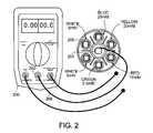
- FIGS. 2-7a series of diagrams illustrate measuring two capacitance values provided by a motor run capacitor such as a Turbo200TM.
- a capacitance of 7.5 micro-Faradis needed to replace a fan motor capacitor while a capacitance of 55.5 micro-Farad is needed to replace a compressor capacitor of an air conditioning unit.
- a common port 202 of a dual display capacitance meter 200is connected to a common connector 204 of a motor run capacitor via a common lead 208 .
- the motor run capacitorincludes six discrete capacitances (e.g., 2.5 micro-Farad, 5 micro-Farad, 5 micro-Farad, 10 micro-Farad, 20 micro-Farad and 25 micro-Farad) that may be used individually or in combination to produce the replacement capacitors (e.g., a fan motor replacement capacitor, a compressor replacement capacitor, etc.).
- the replacement capacitorse.g., a fan motor replacement capacitor, a compressor replacement capacitor, etc.
- a color-coded tabis used identify each discrete capacitance (e.g., a green tab for 2.5 micro-Farad capacitance, white tabs for 5 micro-Farad capacitances, a red tab for a 10 micro-Farad capacitance, a yellow tab for a 20 micro-Farad capacitance, a blue tab for a 25 micro-Farad capacitance).
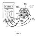
- the 5 micro-Farad capacitoris connected in parallel with one of the 2.5 micro-Farad capacitors, for example.
- a capacitance measurement port 300is connected to the 5 micro-Farad capacitor 302 via a lead 304 .
- the capacitance measurement port 300is capable of measuring capacitance values in a fixed range between 0 micro-Farad and 20 micro-Farad. While this capacitance range may be typical for fan motors of air conditioning units, in some arrangements, this range may be larger or smaller. Furthermore, the capacitance ranges may extend beyond 20 micro-Farad as an upper limit.
- the lower limitmay be larger than 0 micro-Farad.
- the capacitance rangemay be selectable by a user.
- a selector 306 included in the metermay be used to select a capacitance range.
- Other parametersmay be selected with use of the selector. For example, display precision (e.g., tenths of micro-Farad, hundredths of a micro-Farad, etc.) may be selected by a user.
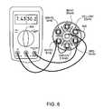
- a jumper lead 400connects the 5 micro-Farad capacitor to the 2.5 micro-Farad capacitor. Based upon this connection, the measured capacitance value increases from 4.58 micro-Farad (shown in FIG. 3 ) to 7.43 micro-Farad as shown in a left hand side display 402 . Due to tolerance levels, the measured capacitance may not exactly match the numerical sum of the capacitance values. In this example, the capacitance sum of the capacitors is 7.5 micro-Farad while the measured capacitance value is 7.43 micro-Farad. Dependent upon the use of this combination of capacitors, this capacitance may or may not be within an acceptable tolerance.
- a meter port 500 for measuring a compressor replacement capacitoris connected to a connector 502 of a 10 micro-Farad capacitor included in the motor capacitor, via a lead 504 .
- a numerical value of 10.2 micro-Faradis presented to represent the measured capacitance of the 10 micro-Farad capacitor.
- a jumper lead 600is used to connect the 10 micro-Farad capacitor in parallel with a 20 micro-Farad capacitor included in the motor run capacitor.
- the measured capacitancehas increased to 30.2 micro-Farad corresponding to connecting the 20 micro-Farad and 10 micro-Farad capacitors in parallel.
- each displayis presenting data with different precision.
- the left-hand displayis presenting data in hundredths of a micro-Farad while the right-hand display is presenting data in tenths of a micro-Farad.
- both displaysmay present data with equivalent levels of precision.
- datamay be presented with more or less precisions (e.g., thousandths of a micro-Farad).
- the precision displayedmay be selected by a user via the selector 306 .
- another jumper 700connects a 25 micro-Farad capacitor in parallel to the parallel combination of the 20 micro-Farad capacitor and the 10 micro-Farad capacitor.
- the right-hand display 506 of the dual capacitor meterpresents the numerical value (e.g., 55.5 micro-Farad) that represents the combined capacitance of the parallel connected capacitors.
- Each of the capacitance meters described in FIGS. 2-7includes a button labeled “power”, a button labeled “hold”, and a circular selector switch.
- the power buttonallows a technician to turn the meter on or off.
- the hold buttonBy pressing the hold button, in some arrangements, data currently being presented in both displays continues to be presented until an event is detected (e.g., pressing the hold button for a second time).
- a technicianis allowed to change lead connections (e.g., disconnect one or more leads) without losing the data being presented on the displays.
- the circular selectormay be used to change measurement parameters such as the capacitance range being used by one or more capacitance measurement circuits.
- the circular selectormay also be used to change presentation parameters of one or both of the displays. For example, the precision of the numerical values displayed on one or both of the displays may be controlled by the circular selector.
- various network connectionsmay be incorporated into the dual display meter.
- network connectionse.g., wireless connections, hardwire connections, etc
- datamay be passed between the meter and other digital devices (e.g., computer systems, cellular phones, etc.) by using one or more network protocols or other similar networking techniques.
- a flowchart 1400that represents some of the operations of one or both of the display drivers 106 , 108 is shown.
- Operations of the display drivers 106 , 108may be provided by one or more processors such as general purpose processors (e.g., a microprocessor) or specialized processors or other type of electrical circuitry (e.g., analog circuitry, digital circuitry, etc.).
- operations for display drivers 106 and 108may be executed separately or jointly by one or more processors or electrical circuits.
- Operations of the display driver 106include receiving 1402 data from a measurement circuit such as capacitance measurement circuit 110 .
- the received datamay be provided in one or more forms such as an analog signal, a digital signal or combination thereof.
- Operationsalso include processing 1404 the received data in preparation of displaying the data.
- the datamay be converted from a format native to the measurement circuit into a format recognizable by a display module. Conversions may be based upon data provided by other portions of the capacitance meter.
- the position of a selector located on the outer face of the capacitance metermay provide data pertinent to the display data.
- Numerical precision, measurement range, capacitance unitse.g., micro-Farads, pico-Farads, etc.
- This datamay also be provided from a data storage device (e.g., memory, magnetic media, etc.) included in the capacitance meter.
- Other processing operationsmay include calibrating the measurement data. For example, data representative of measurement variations from standard (e.g., a capacitor with known capacitance) may be applied to the measurement data for calibration. Other processing techniques such as data averaging and calculating higher order statistics may be performed for application to the measurement data or other data.
- Operationsmay also include providing 1406 the processed data to a display module.
- the display driver 106may provide data to display module 101 for presentation on the display 102 .
- the provided datamay comply with one or more formats (e.g., signal level, protocols, etc.) such that the data is recognizable by the display module.
- the operations presented in the flow chartmay be executed in a repetitive manner so that the display is rapidly refreshed. In some implementations, execution of the operations may be multiplexed with the execution of other operations (e.g., operations of another display driver).
- one or more processorsmay execute instructions to perform the operations of the display driver 106 , e.g., represented in flowchart 1400 .
- one or more general processorse.g., a microprocessor
- one or more specialized devicese.g., an application specific integrated circuit (ASIC), etc.
- ASICapplication specific integrated circuit
- One or more of the processorsmay be implemented in a single integrated circuit as a monolithic structure or in a distributed structure.
- the instructions that are executed by the processorsmay reside in a memory (e.g., random access memory (RAM), read-only memory (ROM), static RAM (SRAM), etc.).
- the instructionsmay also be stored on one or more mass storage devices (e.g., magnetic, magneto-optical disks, or optical disks, etc.).
- One or more of the operations associated with the display driver 106may be performed by one or more programmable processors (e.g., a microprocessor, an ASIC, etc.) executing a computer program.
- the execution of one or more computer programsmay include operating on input data (e.g., measurement data, a selector position, etc.) and generating output (e.g., providing display data on an output port, etc.).
- the operationsmay also be performed by a processor implemented as special purpose logic circuitry (e.g., an FPGA (field programmable gate array), an ASIC (application-specific integrated circuit), etc.).
- Operation executionmay also be executed by digital electronic circuitry, or in computer hardware, firmware, software, or in combinations of them.
- the operations described in flowchart 1400may be implemented as a computer program product, e.g., a computer program tangibly embodied in an information carrier, e.g., in a machine-readable storage device (e.g., RAM, ROM, hard-drive, CD-ROM, etc.) or in a propagated signal.
- the computer program productmay be executed by or control the operation of, data processing apparatus, e.g., a programmable processor, a computer, or multiple computers.
- a computer programmay be written in one or more forms of programming languages, including compiled or interpreted languages, and it can be deployed in any form, including as a stand-alone program or as a module, component, subroutine, or other unit suitable for use in a computing environment.
- a computer programmay be deployed to be executed on one computing device (e.g., controller, computer system, etc.) or on multiple computing devices (e.g., multiple controllers) at one site or distributed across multiple sites and interconnected by a communication network.
Landscapes
- Physics & Mathematics (AREA)
- General Physics & Mathematics (AREA)
- Measurement Of Resistance Or Impedance (AREA)
Abstract
Description
Claims (19)
Priority Applications (2)
| Application Number | Priority Date | Filing Date | Title |
|---|---|---|---|
| US11/621,428US7619420B2 (en) | 2006-08-21 | 2007-01-09 | Capacitance measurement device |
| PCT/US2007/065674WO2008024530A2 (en) | 2006-08-21 | 2007-03-30 | Capacitance measurement device |
Applications Claiming Priority (2)
| Application Number | Priority Date | Filing Date | Title |
|---|---|---|---|
| US83905806P | 2006-08-21 | 2006-08-21 | |
| US11/621,428US7619420B2 (en) | 2006-08-21 | 2007-01-09 | Capacitance measurement device |
Publications (2)
| Publication Number | Publication Date |
|---|---|
| US20080042641A1 US20080042641A1 (en) | 2008-02-21 |
| US7619420B2true US7619420B2 (en) | 2009-11-17 |
Family
ID=39100790
Family Applications (1)
| Application Number | Title | Priority Date | Filing Date |
|---|---|---|---|
| US11/621,428ActiveUS7619420B2 (en) | 2006-08-21 | 2007-01-09 | Capacitance measurement device |
Country Status (2)
| Country | Link |
|---|---|
| US (1) | US7619420B2 (en) |
| WO (1) | WO2008024530A2 (en) |
Cited By (24)
| Publication number | Priority date | Publication date | Assignee | Title |
|---|---|---|---|---|
| US20110311371A1 (en)* | 2008-03-10 | 2011-12-22 | James Ryan Johnson | Methods and apparatus for coupling capacitors |
| US20130152419A1 (en)* | 2007-01-05 | 2013-06-20 | Robert Stockman | Multiple Display Electronic Caliper |
| US20140022954A1 (en)* | 2011-02-08 | 2014-01-23 | Macheen, Inc. | System and Method for Providing Broadband Wireless Access to a Network on a White Label Basis |
| USD906247S1 (en) | 2019-07-11 | 2020-12-29 | American Radionic Company, Inc. | Capacitor |
| US11177074B1 (en) | 2005-04-07 | 2021-11-16 | Amrad Manufacturing, Llc | Capacitor for multiple replacement applications |
| US11183338B2 (en) | 2005-04-07 | 2021-11-23 | Amrad Manufacturing, Llc | Capacitor with multiple elements for multiple replacement applications |
| US11183330B2 (en) | 2018-12-28 | 2021-11-23 | Amrad Manufacturing, Llc | Capacitor with multiple elements for multiple replacement applications |
| US11183337B1 (en) | 2005-04-07 | 2021-11-23 | Amrad Manufacturing, Llc | Capacitor with multiple elements for multiple replacement applications |
| US11183341B1 (en) | 2006-12-29 | 2021-11-23 | Amrad Manufacturing, Llc | Electrolytic capacitive device |
| US11183336B2 (en) | 2005-04-07 | 2021-11-23 | Amrad Manufacturing, Llc | Capacitor with multiple elements for multiple replacement applications |
| US11183335B2 (en) | 2013-05-21 | 2021-11-23 | Amrad Manufacturing, Llc | Power factor correction capacitors |
| US11189426B1 (en) | 2005-04-07 | 2021-11-30 | Amrad Manufacturing, Llc | Capacitor with multiple elements for multiple replacement applications |
| US11195663B2 (en) | 2017-05-12 | 2021-12-07 | Amrad Manufacturing, Llc | Capacitor with multiple elements for multiple replacement applications |
| US11424077B1 (en) | 2017-12-13 | 2022-08-23 | Amrad Manufacturing, Llc | Hard start kit for multiple replacement applications |
| US11575298B2 (en) | 2021-04-30 | 2023-02-07 | Amrad Manufacturing, Llc | Hard start kit for multiple replacement applications |
| USD1045798S1 (en) | 2005-12-23 | 2024-10-08 | Amrad Manufacturing, Llc | Capacitor |
| US12125645B1 (en) | 2019-06-07 | 2024-10-22 | Amrad Manufacturing, Llc | Capacitor with multiple elements for multiple replacement applications |
| USD1052528S1 (en) | 2019-06-25 | 2024-11-26 | Amrad Manufacturing, Llc | Capacitor |
| USD1054379S1 (en) | 2020-11-24 | 2024-12-17 | Amrad Manufacturing, Llc | Capacitor with relay |
| USD1055860S1 (en) | 2018-12-13 | 2024-12-31 | Amrad Manufacturing, Llc | Magnet for attachment to a capacitor |
| US12224131B1 (en) | 2009-11-13 | 2025-02-11 | Amrad Manufacturing, Llc | Hard start kit for multiple replacement applications |
| US12260998B2 (en) | 2005-04-07 | 2025-03-25 | Amrad Manufacturing, Llc | Capacitor with multiple elements for multiple replacement applications |
| US12272503B2 (en) | 2017-05-12 | 2025-04-08 | Amrad Manufacturing, Llc | Capacitor with multiple elements for multiple replacement applications |
| US12437918B2 (en) | 2023-09-22 | 2025-10-07 | Amrad Manufacturing, Llc | Capacitor mount |
Families Citing this family (9)
| Publication number | Priority date | Publication date | Assignee | Title |
|---|---|---|---|---|
| US9367166B1 (en)* | 2007-12-21 | 2016-06-14 | Cypress Semiconductor Corporation | System and method of visualizing capacitance sensing system operation |
| TW201128499A (en)* | 2010-02-04 | 2011-08-16 | Novatek Microelectronics Corp | Touch sensing system, capacitance sensing circuit and capacitance sensing method thereof |
| US8688393B2 (en) | 2010-07-29 | 2014-04-01 | Medtronic, Inc. | Techniques for approximating a difference between two capacitances |
| CN102565543A (en)* | 2012-01-04 | 2012-07-11 | 宁波美康盛德生物科技有限公司 | Distributed capacitance detection device |
| US8933712B2 (en) | 2012-01-31 | 2015-01-13 | Medtronic, Inc. | Servo techniques for approximation of differential capacitance of a sensor |
| US10095659B2 (en) | 2012-08-03 | 2018-10-09 | Fluke Corporation | Handheld devices, systems, and methods for measuring parameters |
| US20140035607A1 (en)* | 2012-08-03 | 2014-02-06 | Fluke Corporation | Handheld Devices, Systems, and Methods for Measuring Parameters |
| US10337962B2 (en) | 2013-03-15 | 2019-07-02 | Fluke Corporation | Visible audiovisual annotation of infrared images using a separate wireless mobile device |
| US9766270B2 (en) | 2013-12-30 | 2017-09-19 | Fluke Corporation | Wireless test measurement |
Citations (24)
| Publication number | Priority date | Publication date | Assignee | Title |
|---|---|---|---|---|
| US3304473A (en) | 1963-11-12 | 1967-02-14 | Sprague Electric Co | Nonbursting electrical capacitor |
| US3377510A (en) | 1967-11-09 | 1968-04-09 | Gen Electric | Electrical apparatus |
| US3921041A (en) | 1975-02-24 | 1975-11-18 | American Radionic | Dual capacitor |
| US4028595A (en) | 1975-12-02 | 1977-06-07 | American Radionic Co., Inc. | Multi-voltage capacitor section |
| US4106068A (en) | 1977-01-27 | 1978-08-08 | General Electric Company | Pressure sensitive interrupter |
| US4112474A (en) | 1977-01-27 | 1978-09-05 | General Electric Company | Capacitor protective device |
| US4209815A (en) | 1978-04-17 | 1980-06-24 | Jard, Inc. | Capacitor protective circuit |
| US4240126A (en) | 1979-02-16 | 1980-12-16 | Icar Industria Condensatori Applicazioni Elettroelettroniche S.P.A. | Electric capacitor constructed to prevent explosion |
| US4263638A (en) | 1979-06-25 | 1981-04-21 | American Radionic Co., Inc. | Dial wound capacitor and method of making same |
| US4312027A (en) | 1980-07-21 | 1982-01-19 | American Radionic Co., Inc. | Multiple capacitor winding with electrostatic shielding |
| US4326237A (en)* | 1981-01-02 | 1982-04-20 | Sprague Electric Company | Dual AC motor-run capacitors |
| US4352145A (en) | 1980-11-05 | 1982-09-28 | American Radionic Co., Inc. | Multiple element cylindrical metallized film capacitors and method of making the same |
| US4447854A (en) | 1982-11-22 | 1984-05-08 | Sprague Electric Company | Oval dual-AC-capacitor package |
| US4558394A (en) | 1984-04-02 | 1985-12-10 | American Radionic Co., Inc. | Capacitor unit with multiple selectable capacitance values |
| US4754361A (en) | 1986-01-20 | 1988-06-28 | Ducati Energia, S.P.A. | Resinated capacitive-body capacitor with interspace and explosion-preventing device |
| US4812941A (en) | 1987-08-19 | 1989-03-14 | Magnetec Corporation | Capacitor and method of manufacture |
| US4825147A (en) | 1988-09-14 | 1989-04-25 | Sencore, Inc. | Capacitance measuring method and apparatus |
| US4897760A (en) | 1988-06-29 | 1990-01-30 | Aerovox, Inc. | Capacitor disconnection |
| US5019934A (en) | 1986-06-04 | 1991-05-28 | Aerovox Incorporated | Capacitor circuit interruption |
| US5122733A (en) | 1986-01-15 | 1992-06-16 | Karel Havel | Variable color digital multimeter |
| US5138519A (en) | 1991-09-16 | 1992-08-11 | Stockman Robert M | Selectively variable capacitor |
| US6084764A (en) | 1998-12-21 | 2000-07-04 | Hamilton Sundstrand Corporation | Capacitor disconnecting assembly |
| US20040100288A1 (en)* | 2002-11-07 | 2004-05-27 | Taiwan Semiconductor Manufacturing Co., Ltd. | Capacitance probe for suface dielectric constant measurements |
| US7203053B2 (en)* | 2005-04-07 | 2007-04-10 | American Radionic Company, Inc. | Capacitor for multiple replacement applications |
- 2007
- 2007-01-09USUS11/621,428patent/US7619420B2/enactiveActive
- 2007-03-30WOPCT/US2007/065674patent/WO2008024530A2/enactiveApplication Filing
Patent Citations (24)
| Publication number | Priority date | Publication date | Assignee | Title |
|---|---|---|---|---|
| US3304473A (en) | 1963-11-12 | 1967-02-14 | Sprague Electric Co | Nonbursting electrical capacitor |
| US3377510A (en) | 1967-11-09 | 1968-04-09 | Gen Electric | Electrical apparatus |
| US3921041A (en) | 1975-02-24 | 1975-11-18 | American Radionic | Dual capacitor |
| US4028595A (en) | 1975-12-02 | 1977-06-07 | American Radionic Co., Inc. | Multi-voltage capacitor section |
| US4106068A (en) | 1977-01-27 | 1978-08-08 | General Electric Company | Pressure sensitive interrupter |
| US4112474A (en) | 1977-01-27 | 1978-09-05 | General Electric Company | Capacitor protective device |
| US4209815A (en) | 1978-04-17 | 1980-06-24 | Jard, Inc. | Capacitor protective circuit |
| US4240126A (en) | 1979-02-16 | 1980-12-16 | Icar Industria Condensatori Applicazioni Elettroelettroniche S.P.A. | Electric capacitor constructed to prevent explosion |
| US4263638A (en) | 1979-06-25 | 1981-04-21 | American Radionic Co., Inc. | Dial wound capacitor and method of making same |
| US4312027A (en) | 1980-07-21 | 1982-01-19 | American Radionic Co., Inc. | Multiple capacitor winding with electrostatic shielding |
| US4352145A (en) | 1980-11-05 | 1982-09-28 | American Radionic Co., Inc. | Multiple element cylindrical metallized film capacitors and method of making the same |
| US4326237A (en)* | 1981-01-02 | 1982-04-20 | Sprague Electric Company | Dual AC motor-run capacitors |
| US4447854A (en) | 1982-11-22 | 1984-05-08 | Sprague Electric Company | Oval dual-AC-capacitor package |
| US4558394A (en) | 1984-04-02 | 1985-12-10 | American Radionic Co., Inc. | Capacitor unit with multiple selectable capacitance values |
| US5122733A (en) | 1986-01-15 | 1992-06-16 | Karel Havel | Variable color digital multimeter |
| US4754361A (en) | 1986-01-20 | 1988-06-28 | Ducati Energia, S.P.A. | Resinated capacitive-body capacitor with interspace and explosion-preventing device |
| US5019934A (en) | 1986-06-04 | 1991-05-28 | Aerovox Incorporated | Capacitor circuit interruption |
| US4812941A (en) | 1987-08-19 | 1989-03-14 | Magnetec Corporation | Capacitor and method of manufacture |
| US4897760A (en) | 1988-06-29 | 1990-01-30 | Aerovox, Inc. | Capacitor disconnection |
| US4825147A (en) | 1988-09-14 | 1989-04-25 | Sencore, Inc. | Capacitance measuring method and apparatus |
| US5138519A (en) | 1991-09-16 | 1992-08-11 | Stockman Robert M | Selectively variable capacitor |
| US6084764A (en) | 1998-12-21 | 2000-07-04 | Hamilton Sundstrand Corporation | Capacitor disconnecting assembly |
| US20040100288A1 (en)* | 2002-11-07 | 2004-05-27 | Taiwan Semiconductor Manufacturing Co., Ltd. | Capacitance probe for suface dielectric constant measurements |
| US7203053B2 (en)* | 2005-04-07 | 2007-04-10 | American Radionic Company, Inc. | Capacitor for multiple replacement applications |
Non-Patent Citations (7)
| Title |
|---|
| Agilent 4284A/4285A Precision LCR Meter Family Overview, Agilent Technologies, Inc., Printed May 7, 2004.* |
| Agilent 4284A/4285A Precision LCR Meter Family, Technical Overview, Printed May 2004 (Reference furnished to applicant in a previous office action).* |
| Agilent 4284A/4285A Precision LCR Meter Family, Technical Overview, Printed May 2004.* |
| Agilent Application Note E5250A-3, "Accurate and Efficient C-V Measurements", Copyright 2000, Agilent Technologies, Printed Nov. 2000 (Reference furnished to applicant in a previous office action).* |
| Agilent Application Note E5250A-3, "Accurate and Efficient C-V Measurements", Copyright 2000, Agilent Technologies, Printed Nov. 2000.* |
| American Radionic "American Radionic Introduces Capacitors Without Compromise" (Advertisement); 1989. |
| PCT International Search Report and Written Opinion, mailed Feb. 8, 2008. 10 pages. International Application No. PCT/US 07/65674 filed Mar. 30, 2007. |
Cited By (49)
| Publication number | Priority date | Publication date | Assignee | Title |
|---|---|---|---|---|
| US11183337B1 (en) | 2005-04-07 | 2021-11-23 | Amrad Manufacturing, Llc | Capacitor with multiple elements for multiple replacement applications |
| US12278059B2 (en) | 2005-04-07 | 2025-04-15 | Amrad Manufacturing, Llc | Capacitor with multiple elements for multiple replacement applications |
| US12272501B2 (en) | 2005-04-07 | 2025-04-08 | Amrad Manufacturing, Llc | Capacitor for multiple replacement applications |
| US12260998B2 (en) | 2005-04-07 | 2025-03-25 | Amrad Manufacturing, Llc | Capacitor with multiple elements for multiple replacement applications |
| US12230452B1 (en) | 2005-04-07 | 2025-02-18 | Amrad Manufacturing, Llc | Capacitor with multiple elements for multiple replacement applications |
| US12224132B1 (en) | 2005-04-07 | 2025-02-11 | Amrad Manufacturing, Llc | Capacitor with multiple elements for multiple replacement applications |
| US11651903B1 (en) | 2005-04-07 | 2023-05-16 | Amrad Manufacturing, Llc | Capacitor for multiple replacement applications |
| US11189426B1 (en) | 2005-04-07 | 2021-11-30 | Amrad Manufacturing, Llc | Capacitor with multiple elements for multiple replacement applications |
| US11183336B2 (en) | 2005-04-07 | 2021-11-23 | Amrad Manufacturing, Llc | Capacitor with multiple elements for multiple replacement applications |
| US11177074B1 (en) | 2005-04-07 | 2021-11-16 | Amrad Manufacturing, Llc | Capacitor for multiple replacement applications |
| US11183338B2 (en) | 2005-04-07 | 2021-11-23 | Amrad Manufacturing, Llc | Capacitor with multiple elements for multiple replacement applications |
| USD1045798S1 (en) | 2005-12-23 | 2024-10-08 | Amrad Manufacturing, Llc | Capacitor |
| US11631550B2 (en) | 2006-12-29 | 2023-04-18 | Amrad Manufacturing, Llc | Electrolytic capacitor with multiple sections |
| US11183341B1 (en) | 2006-12-29 | 2021-11-23 | Amrad Manufacturing, Llc | Electrolytic capacitive device |
| US12293879B2 (en) | 2006-12-29 | 2025-05-06 | Amrad Manufacturing, Llc | Electrolytic capacitive device |
| US20130152419A1 (en)* | 2007-01-05 | 2013-06-20 | Robert Stockman | Multiple Display Electronic Caliper |
| US9316474B2 (en)* | 2007-01-05 | 2016-04-19 | American Radionic Company, Inc. | Multiple display electronic caliper |
| US11215438B2 (en) | 2007-01-05 | 2022-01-04 | Dynamic Engineering Innovations, Inc. | Multiple display electronic caliper |
| US10054417B2 (en) | 2007-01-05 | 2018-08-21 | American Radionic Company, Inc. | Multiple display electronic caliper |
| US20190195610A1 (en)* | 2007-01-05 | 2019-06-27 | American Radionic Company, Inc. | Multiple Display Electronic Caliper |
| US20110311371A1 (en)* | 2008-03-10 | 2011-12-22 | James Ryan Johnson | Methods and apparatus for coupling capacitors |
| US8336207B2 (en)* | 2008-03-10 | 2012-12-25 | Rbc Manufacturing Corporation | Methods and apparatus for coupling capacitors |
| US12237115B1 (en) | 2009-11-13 | 2025-02-25 | Amrad Manufacturing Llc | Hard start kit for multiple replacement applications |
| US12224131B1 (en) | 2009-11-13 | 2025-02-11 | Amrad Manufacturing, Llc | Hard start kit for multiple replacement applications |
| US10133450B2 (en) | 2011-02-08 | 2018-11-20 | Blackberry Limited | System and method for task specific, metered bandwidth control within shared client environment on mobile communications platforms |
| US20140022954A1 (en)* | 2011-02-08 | 2014-01-23 | Macheen, Inc. | System and Method for Providing Broadband Wireless Access to a Network on a White Label Basis |
| US11183335B2 (en) | 2013-05-21 | 2021-11-23 | Amrad Manufacturing, Llc | Power factor correction capacitors |
| US12230451B2 (en) | 2013-05-21 | 2025-02-18 | Amrad Manufacturing, Llc | Power factor correction capacitors |
| US11189425B1 (en) | 2013-05-21 | 2021-11-30 | Amrad Manufacturing, Llc | Power factor correction capacitors |
| US12260997B2 (en) | 2017-05-12 | 2025-03-25 | Amrad Manufacturing, Llc | Capacitor with multiple elements for multiple replacement applications |
| US12272503B2 (en) | 2017-05-12 | 2025-04-08 | Amrad Manufacturing, Llc | Capacitor with multiple elements for multiple replacement applications |
| US12211655B2 (en) | 2017-05-12 | 2025-01-28 | Amrad Manufacturing, Llc | Capacitor with multiple elements for multiple replacement applications |
| US12308179B2 (en) | 2017-05-12 | 2025-05-20 | Amrad Manufacturing, Llc | Capacitor with multiple elements for multiple replacement applications |
| US11195663B2 (en) | 2017-05-12 | 2021-12-07 | Amrad Manufacturing, Llc | Capacitor with multiple elements for multiple replacement applications |
| US12191087B2 (en) | 2017-05-12 | 2025-01-07 | Amrad Manufacturing, Llc | Capacitor with multiple elements for multiple replacement applications |
| US11424077B1 (en) | 2017-12-13 | 2022-08-23 | Amrad Manufacturing, Llc | Hard start kit for multiple replacement applications |
| USD1055860S1 (en) | 2018-12-13 | 2024-12-31 | Amrad Manufacturing, Llc | Magnet for attachment to a capacitor |
| US12315679B2 (en) | 2018-12-28 | 2025-05-27 | Amrad Manufacturing, Llc | Capacitor with multiple elements for multiple replacement applications |
| US12230447B2 (en) | 2018-12-28 | 2025-02-18 | Amrad Manufacturing, Llc | Capacitor with multiple elements for multiple replacement applications |
| US11183330B2 (en) | 2018-12-28 | 2021-11-23 | Amrad Manufacturing, Llc | Capacitor with multiple elements for multiple replacement applications |
| US12125645B1 (en) | 2019-06-07 | 2024-10-22 | Amrad Manufacturing, Llc | Capacitor with multiple elements for multiple replacement applications |
| USD1052528S1 (en) | 2019-06-25 | 2024-11-26 | Amrad Manufacturing, Llc | Capacitor |
| USD1054986S1 (en) | 2019-06-25 | 2024-12-24 | Amrad Manufacturing, Llc | Capacitor |
| USD906247S1 (en) | 2019-07-11 | 2020-12-29 | American Radionic Company, Inc. | Capacitor |
| USD1059290S1 (en) | 2019-07-11 | 2025-01-28 | Amrad Manufacturing, Llc | Capacitor |
| USD1054379S1 (en) | 2020-11-24 | 2024-12-17 | Amrad Manufacturing, Llc | Capacitor with relay |
| US12260991B2 (en) | 2021-04-30 | 2025-03-25 | Amrad Manufacturing, Llc | Hard start kit for multiple replacement applications |
| US11575298B2 (en) | 2021-04-30 | 2023-02-07 | Amrad Manufacturing, Llc | Hard start kit for multiple replacement applications |
| US12437918B2 (en) | 2023-09-22 | 2025-10-07 | Amrad Manufacturing, Llc | Capacitor mount |
Also Published As
| Publication number | Publication date |
|---|---|
| US20080042641A1 (en) | 2008-02-21 |
| WO2008024530A2 (en) | 2008-02-28 |
| WO2008024530A3 (en) | 2008-04-10 |
Similar Documents
| Publication | Publication Date | Title |
|---|---|---|
| US7619420B2 (en) | Capacitance measurement device | |
| US5386188A (en) | In-circuit current measurement | |
| US9983061B2 (en) | Method, apparatus and system for testing optical characteristics of display module | |
| KR100485739B1 (en) | Testing method and testing device for semiconductor integrated circuits | |
| CN100494949C (en) | Universal automobile meter tester and its test method | |
| TWI435093B (en) | Detection circuit of display panel | |
| CN109143032B (en) | Circuit board self-detection system | |
| US20100127711A1 (en) | Testing apparatus for testing electronic system with 4-wires resistive touch panel and the method therefor | |
| US20100117639A1 (en) | Endurance testing system and method | |
| US8111920B2 (en) | Closed-loop integrity monitor | |
| KR900004372B1 (en) | Fault diagnosis system of automotive electronics | |
| US7088108B2 (en) | Method for detecting an offset drift in a wheatstone measuring bridge | |
| CN109949726A (en) | A kind of LED display mould group automatic white balance debugging system and adjustment method | |
| EP0388523A2 (en) | Apparatus for displaying residual capacity of battery | |
| CN104198921A (en) | Method for testing printed circuit boards | |
| CN210689661U (en) | Gyroscope calibration circuit and device | |
| JPH10334035A (en) | Information processor | |
| CN203720647U (en) | Air data computer testing system | |
| CN207730842U (en) | A kind of cable line sequence detection device | |
| KR19980042236A (en) | Fault diagnosis device | |
| CN116125256A (en) | Parameter testing method and system for comparator | |
| CN110907721A (en) | Control panel test system | |
| KR200458112Y1 (en) | Diagnostic Jig for Multimedia Display | |
| KR20040042616A (en) | High speed measuring system of resistance | |
| CN111443307A (en) | Detection method and detection system of signal processing unit |
Legal Events
| Date | Code | Title | Description |
|---|---|---|---|
| AS | Assignment | Owner name:AMERICAN RADIONIC COMPANY, INC., FLORIDA Free format text:ASSIGNMENT OF ASSIGNORS INTEREST;ASSIGNOR:STOCKMAN, ROBERT M.;REEL/FRAME:019250/0342 Effective date:20070503 | |
| STCF | Information on status: patent grant | Free format text:PATENTED CASE | |
| FPAY | Fee payment | Year of fee payment:4 | |
| FPAY | Fee payment | Year of fee payment:8 | |
| AS | Assignment | Owner name:AMRAD MANUFACTURING, LLC, TEXAS Free format text:ASSIGNMENT OF ASSIGNORS INTEREST;ASSIGNOR:AMERICAN RADIONIC COMPANY, INC.;REEL/FRAME:053488/0675 Effective date:20200730 | |
| AS | Assignment | Owner name:FROST BANK, TEXAS Free format text:SECURITY INTEREST;ASSIGNOR:AMRAD MANUFACTURING, LLC;REEL/FRAME:053599/0324 Effective date:20200730 | |
| MAFP | Maintenance fee payment | Free format text:PAYMENT OF MAINTENANCE FEE, 12TH YR, SMALL ENTITY (ORIGINAL EVENT CODE: M2553); ENTITY STATUS OF PATENT OWNER: SMALL ENTITY Year of fee payment:12 | |
| AS | Assignment | Owner name:AMRAD MANUFACTURING, LLC, TEXAS Free format text:RELEASE BY SECURED PARTY;ASSIGNOR:FROST BANK;REEL/FRAME:069475/0217 Effective date:20241129 Owner name:VLADMIR, LTD., TEXAS Free format text:RELEASE BY SECURED PARTY;ASSIGNOR:FROST BANK;REEL/FRAME:069475/0217 Effective date:20241129 | |
| AS | Assignment | Owner name:HVAC SOUTH, LLC, CALIFORNIA Free format text:CONFIRMATORY ASSIGNMENT;ASSIGNOR:AMRAD MANUFACTURING, LLC;REEL/FRAME:071738/0759 Effective date:20250331 |