US7618451B2 - Patient selectable joint arthroplasty devices and surgical tools facilitating increased accuracy, speed and simplicity in performing total and partial joint arthroplasty - Google Patents
Patient selectable joint arthroplasty devices and surgical tools facilitating increased accuracy, speed and simplicity in performing total and partial joint arthroplastyDownload PDFInfo
- Publication number
- US7618451B2 US7618451B2US10/724,010US72401003AUS7618451B2US 7618451 B2US7618451 B2US 7618451B2US 72401003 AUS72401003 AUS 72401003AUS 7618451 B2US7618451 B2US 7618451B2
- Authority
- US
- United States
- Prior art keywords
- cartilage
- tool
- joint
- component
- articular
- Prior art date
- Legal status (The legal status is an assumption and is not a legal conclusion. Google has not performed a legal analysis and makes no representation as to the accuracy of the status listed.)
- Expired - Lifetime
Links
Images


Classifications
- A—HUMAN NECESSITIES
- A61—MEDICAL OR VETERINARY SCIENCE; HYGIENE
- A61F—FILTERS IMPLANTABLE INTO BLOOD VESSELS; PROSTHESES; DEVICES PROVIDING PATENCY TO, OR PREVENTING COLLAPSING OF, TUBULAR STRUCTURES OF THE BODY, e.g. STENTS; ORTHOPAEDIC, NURSING OR CONTRACEPTIVE DEVICES; FOMENTATION; TREATMENT OR PROTECTION OF EYES OR EARS; BANDAGES, DRESSINGS OR ABSORBENT PADS; FIRST-AID KITS
- A61F2/00—Filters implantable into blood vessels; Prostheses, i.e. artificial substitutes or replacements for parts of the body; Appliances for connecting them with the body; Devices providing patency to, or preventing collapsing of, tubular structures of the body, e.g. stents
- A61F2/02—Prostheses implantable into the body
- A61F2/30—Joints
- A61F2/30756—Cartilage endoprostheses
- A—HUMAN NECESSITIES
- A61—MEDICAL OR VETERINARY SCIENCE; HYGIENE
- A61B—DIAGNOSIS; SURGERY; IDENTIFICATION
- A61B17/00—Surgical instruments, devices or methods
- A61B17/14—Surgical saws
- A61B17/15—Guides therefor
- A—HUMAN NECESSITIES
- A61—MEDICAL OR VETERINARY SCIENCE; HYGIENE
- A61B—DIAGNOSIS; SURGERY; IDENTIFICATION
- A61B17/00—Surgical instruments, devices or methods
- A61B17/14—Surgical saws
- A61B17/15—Guides therefor
- A61B17/154—Guides therefor for preparing bone for knee prosthesis
- A61B17/155—Cutting femur
- A—HUMAN NECESSITIES
- A61—MEDICAL OR VETERINARY SCIENCE; HYGIENE
- A61B—DIAGNOSIS; SURGERY; IDENTIFICATION
- A61B17/00—Surgical instruments, devices or methods
- A61B17/14—Surgical saws
- A61B17/15—Guides therefor
- A61B17/154—Guides therefor for preparing bone for knee prosthesis
- A61B17/157—Cutting tibia
- A—HUMAN NECESSITIES
- A61—MEDICAL OR VETERINARY SCIENCE; HYGIENE
- A61B—DIAGNOSIS; SURGERY; IDENTIFICATION
- A61B17/00—Surgical instruments, devices or methods
- A61B17/14—Surgical saws
- A61B17/15—Guides therefor
- A61B17/154—Guides therefor for preparing bone for knee prosthesis
- A61B17/158—Cutting patella
- A—HUMAN NECESSITIES
- A61—MEDICAL OR VETERINARY SCIENCE; HYGIENE
- A61B—DIAGNOSIS; SURGERY; IDENTIFICATION
- A61B17/00—Surgical instruments, devices or methods
- A61B17/16—Instruments for performing osteoclasis; Drills or chisels for bones; Trepans
- A61B17/1662—Instruments for performing osteoclasis; Drills or chisels for bones; Trepans for particular parts of the body
- A61B17/1664—Instruments for performing osteoclasis; Drills or chisels for bones; Trepans for particular parts of the body for the hip
- A61B17/1666—Instruments for performing osteoclasis; Drills or chisels for bones; Trepans for particular parts of the body for the hip for the acetabulum
- A—HUMAN NECESSITIES
- A61—MEDICAL OR VETERINARY SCIENCE; HYGIENE
- A61B—DIAGNOSIS; SURGERY; IDENTIFICATION
- A61B17/00—Surgical instruments, devices or methods
- A61B17/16—Instruments for performing osteoclasis; Drills or chisels for bones; Trepans
- A61B17/1662—Instruments for performing osteoclasis; Drills or chisels for bones; Trepans for particular parts of the body
- A61B17/1664—Instruments for performing osteoclasis; Drills or chisels for bones; Trepans for particular parts of the body for the hip
- A61B17/1668—Instruments for performing osteoclasis; Drills or chisels for bones; Trepans for particular parts of the body for the hip for the upper femur
- A—HUMAN NECESSITIES
- A61—MEDICAL OR VETERINARY SCIENCE; HYGIENE
- A61B—DIAGNOSIS; SURGERY; IDENTIFICATION
- A61B34/00—Computer-aided surgery; Manipulators or robots specially adapted for use in surgery
- A61B34/20—Surgical navigation systems; Devices for tracking or guiding surgical instruments, e.g. for frameless stereotaxis
- A—HUMAN NECESSITIES
- A61—MEDICAL OR VETERINARY SCIENCE; HYGIENE
- A61B—DIAGNOSIS; SURGERY; IDENTIFICATION
- A61B5/00—Measuring for diagnostic purposes; Identification of persons
- A61B5/103—Measuring devices for testing the shape, pattern, colour, size or movement of the body or parts thereof, for diagnostic purposes
- A61B5/107—Measuring physical dimensions, e.g. size of the entire body or parts thereof
- A61B5/1076—Measuring physical dimensions, e.g. size of the entire body or parts thereof for measuring dimensions inside body cavities, e.g. using catheters
- A—HUMAN NECESSITIES
- A61—MEDICAL OR VETERINARY SCIENCE; HYGIENE
- A61B—DIAGNOSIS; SURGERY; IDENTIFICATION
- A61B5/00—Measuring for diagnostic purposes; Identification of persons
- A61B5/103—Measuring devices for testing the shape, pattern, colour, size or movement of the body or parts thereof, for diagnostic purposes
- A61B5/107—Measuring physical dimensions, e.g. size of the entire body or parts thereof
- A61B5/1077—Measuring of profiles
- A—HUMAN NECESSITIES
- A61—MEDICAL OR VETERINARY SCIENCE; HYGIENE
- A61B—DIAGNOSIS; SURGERY; IDENTIFICATION
- A61B5/00—Measuring for diagnostic purposes; Identification of persons
- A61B5/45—For evaluating or diagnosing the musculoskeletal system or teeth
- A61B5/4528—Joints
- A—HUMAN NECESSITIES
- A61—MEDICAL OR VETERINARY SCIENCE; HYGIENE
- A61F—FILTERS IMPLANTABLE INTO BLOOD VESSELS; PROSTHESES; DEVICES PROVIDING PATENCY TO, OR PREVENTING COLLAPSING OF, TUBULAR STRUCTURES OF THE BODY, e.g. STENTS; ORTHOPAEDIC, NURSING OR CONTRACEPTIVE DEVICES; FOMENTATION; TREATMENT OR PROTECTION OF EYES OR EARS; BANDAGES, DRESSINGS OR ABSORBENT PADS; FIRST-AID KITS
- A61F2/00—Filters implantable into blood vessels; Prostheses, i.e. artificial substitutes or replacements for parts of the body; Appliances for connecting them with the body; Devices providing patency to, or preventing collapsing of, tubular structures of the body, e.g. stents
- A61F2/02—Prostheses implantable into the body
- A61F2/30—Joints
- A61F2/3094—Designing or manufacturing processes
- A61F2/30942—Designing or manufacturing processes for designing or making customized prostheses, e.g. using templates, CT or NMR scans, finite-element analysis or CAD-CAM techniques
- A—HUMAN NECESSITIES
- A61—MEDICAL OR VETERINARY SCIENCE; HYGIENE
- A61F—FILTERS IMPLANTABLE INTO BLOOD VESSELS; PROSTHESES; DEVICES PROVIDING PATENCY TO, OR PREVENTING COLLAPSING OF, TUBULAR STRUCTURES OF THE BODY, e.g. STENTS; ORTHOPAEDIC, NURSING OR CONTRACEPTIVE DEVICES; FOMENTATION; TREATMENT OR PROTECTION OF EYES OR EARS; BANDAGES, DRESSINGS OR ABSORBENT PADS; FIRST-AID KITS
- A61F2/00—Filters implantable into blood vessels; Prostheses, i.e. artificial substitutes or replacements for parts of the body; Appliances for connecting them with the body; Devices providing patency to, or preventing collapsing of, tubular structures of the body, e.g. stents
- A61F2/02—Prostheses implantable into the body
- A61F2/30—Joints
- A61F2/46—Special tools for implanting artificial joints
- A61F2/4657—Measuring instruments used for implanting artificial joints
- A—HUMAN NECESSITIES
- A61—MEDICAL OR VETERINARY SCIENCE; HYGIENE
- A61B—DIAGNOSIS; SURGERY; IDENTIFICATION
- A61B17/00—Surgical instruments, devices or methods
- A61B17/16—Instruments for performing osteoclasis; Drills or chisels for bones; Trepans
- A61B17/1662—Instruments for performing osteoclasis; Drills or chisels for bones; Trepans for particular parts of the body
- A—HUMAN NECESSITIES
- A61—MEDICAL OR VETERINARY SCIENCE; HYGIENE
- A61B—DIAGNOSIS; SURGERY; IDENTIFICATION
- A61B17/00—Surgical instruments, devices or methods
- A61B17/56—Surgical instruments or methods for treatment of bones or joints; Devices specially adapted therefor
- A61B17/58—Surgical instruments or methods for treatment of bones or joints; Devices specially adapted therefor for osteosynthesis, e.g. bone plates, screws or setting implements
- A61B17/68—Internal fixation devices, including fasteners and spinal fixators, even if a part thereof projects from the skin
- A61B17/70—Spinal positioners or stabilisers, e.g. stabilisers comprising fluid filler in an implant
- A61B17/7097—Stabilisers comprising fluid filler in an implant, e.g. balloon; devices for inserting or filling such implants
- A61B17/7098—Stabilisers comprising fluid filler in an implant, e.g. balloon; devices for inserting or filling such implants wherein the implant is permeable or has openings, e.g. fenestrated screw
- A—HUMAN NECESSITIES
- A61—MEDICAL OR VETERINARY SCIENCE; HYGIENE
- A61B—DIAGNOSIS; SURGERY; IDENTIFICATION
- A61B17/00—Surgical instruments, devices or methods
- A61B17/56—Surgical instruments or methods for treatment of bones or joints; Devices specially adapted therefor
- A61B17/58—Surgical instruments or methods for treatment of bones or joints; Devices specially adapted therefor for osteosynthesis, e.g. bone plates, screws or setting implements
- A61B17/88—Osteosynthesis instruments; Methods or means for implanting or extracting internal or external fixation devices
- A61B17/8802—Equipment for handling bone cement or other fluid fillers
- A61B17/8805—Equipment for handling bone cement or other fluid fillers for introducing fluid filler into bone or extracting it
- A—HUMAN NECESSITIES
- A61—MEDICAL OR VETERINARY SCIENCE; HYGIENE
- A61B—DIAGNOSIS; SURGERY; IDENTIFICATION
- A61B17/00—Surgical instruments, devices or methods
- A61B17/56—Surgical instruments or methods for treatment of bones or joints; Devices specially adapted therefor
- A61B2017/568—Surgical instruments or methods for treatment of bones or joints; Devices specially adapted therefor produced with shape and dimensions specific for an individual patient
- A—HUMAN NECESSITIES
- A61—MEDICAL OR VETERINARY SCIENCE; HYGIENE
- A61B—DIAGNOSIS; SURGERY; IDENTIFICATION
- A61B34/00—Computer-aided surgery; Manipulators or robots specially adapted for use in surgery
- A61B34/10—Computer-aided planning, simulation or modelling of surgical operations
- A61B2034/101—Computer-aided simulation of surgical operations
- A61B2034/102—Modelling of surgical devices, implants or prosthesis
- A—HUMAN NECESSITIES
- A61—MEDICAL OR VETERINARY SCIENCE; HYGIENE
- A61B—DIAGNOSIS; SURGERY; IDENTIFICATION
- A61B34/00—Computer-aided surgery; Manipulators or robots specially adapted for use in surgery
- A61B34/10—Computer-aided planning, simulation or modelling of surgical operations
- A61B2034/101—Computer-aided simulation of surgical operations
- A61B2034/105—Modelling of the patient, e.g. for ligaments or bones
- A—HUMAN NECESSITIES
- A61—MEDICAL OR VETERINARY SCIENCE; HYGIENE
- A61B—DIAGNOSIS; SURGERY; IDENTIFICATION
- A61B34/00—Computer-aided surgery; Manipulators or robots specially adapted for use in surgery
- A61B34/10—Computer-aided planning, simulation or modelling of surgical operations
- A61B2034/108—Computer aided selection or customisation of medical implants or cutting guides
- A—HUMAN NECESSITIES
- A61—MEDICAL OR VETERINARY SCIENCE; HYGIENE
- A61B—DIAGNOSIS; SURGERY; IDENTIFICATION
- A61B34/00—Computer-aided surgery; Manipulators or robots specially adapted for use in surgery
- A61B34/25—User interfaces for surgical systems
- A61B2034/256—User interfaces for surgical systems having a database of accessory information, e.g. including context sensitive help or scientific articles
- A—HUMAN NECESSITIES
- A61—MEDICAL OR VETERINARY SCIENCE; HYGIENE
- A61B—DIAGNOSIS; SURGERY; IDENTIFICATION
- A61B90/00—Instruments, implements or accessories specially adapted for surgery or diagnosis and not covered by any of the groups A61B1/00 - A61B50/00, e.g. for luxation treatment or for protecting wound edges
- A61B90/06—Measuring instruments not otherwise provided for
- A61B2090/061—Measuring instruments not otherwise provided for for measuring dimensions, e.g. length
- A—HUMAN NECESSITIES
- A61—MEDICAL OR VETERINARY SCIENCE; HYGIENE
- A61B—DIAGNOSIS; SURGERY; IDENTIFICATION
- A61B34/00—Computer-aided surgery; Manipulators or robots specially adapted for use in surgery
- A61B34/10—Computer-aided planning, simulation or modelling of surgical operations
- A—HUMAN NECESSITIES
- A61—MEDICAL OR VETERINARY SCIENCE; HYGIENE
- A61B—DIAGNOSIS; SURGERY; IDENTIFICATION
- A61B5/00—Measuring for diagnostic purposes; Identification of persons
- A61B5/103—Measuring devices for testing the shape, pattern, colour, size or movement of the body or parts thereof, for diagnostic purposes
- A61B5/107—Measuring physical dimensions, e.g. size of the entire body or parts thereof
- A61B5/1075—Measuring physical dimensions, e.g. size of the entire body or parts thereof for measuring dimensions by non-invasive methods, e.g. for determining thickness of tissue layer
- A—HUMAN NECESSITIES
- A61—MEDICAL OR VETERINARY SCIENCE; HYGIENE
- A61B—DIAGNOSIS; SURGERY; IDENTIFICATION
- A61B5/00—Measuring for diagnostic purposes; Identification of persons
- A61B5/45—For evaluating or diagnosing the musculoskeletal system or teeth
- A61B5/4504—Bones
- A—HUMAN NECESSITIES
- A61—MEDICAL OR VETERINARY SCIENCE; HYGIENE
- A61B—DIAGNOSIS; SURGERY; IDENTIFICATION
- A61B5/00—Measuring for diagnostic purposes; Identification of persons
- A61B5/45—For evaluating or diagnosing the musculoskeletal system or teeth
- A61B5/4514—Cartilage
- A—HUMAN NECESSITIES
- A61—MEDICAL OR VETERINARY SCIENCE; HYGIENE
- A61F—FILTERS IMPLANTABLE INTO BLOOD VESSELS; PROSTHESES; DEVICES PROVIDING PATENCY TO, OR PREVENTING COLLAPSING OF, TUBULAR STRUCTURES OF THE BODY, e.g. STENTS; ORTHOPAEDIC, NURSING OR CONTRACEPTIVE DEVICES; FOMENTATION; TREATMENT OR PROTECTION OF EYES OR EARS; BANDAGES, DRESSINGS OR ABSORBENT PADS; FIRST-AID KITS
- A61F2/00—Filters implantable into blood vessels; Prostheses, i.e. artificial substitutes or replacements for parts of the body; Appliances for connecting them with the body; Devices providing patency to, or preventing collapsing of, tubular structures of the body, e.g. stents
- A61F2/02—Prostheses implantable into the body
- A61F2/30—Joints
- A61F2/30767—Special external or bone-contacting surface, e.g. coating for improving bone ingrowth
- A—HUMAN NECESSITIES
- A61—MEDICAL OR VETERINARY SCIENCE; HYGIENE
- A61F—FILTERS IMPLANTABLE INTO BLOOD VESSELS; PROSTHESES; DEVICES PROVIDING PATENCY TO, OR PREVENTING COLLAPSING OF, TUBULAR STRUCTURES OF THE BODY, e.g. STENTS; ORTHOPAEDIC, NURSING OR CONTRACEPTIVE DEVICES; FOMENTATION; TREATMENT OR PROTECTION OF EYES OR EARS; BANDAGES, DRESSINGS OR ABSORBENT PADS; FIRST-AID KITS
- A61F2/00—Filters implantable into blood vessels; Prostheses, i.e. artificial substitutes or replacements for parts of the body; Appliances for connecting them with the body; Devices providing patency to, or preventing collapsing of, tubular structures of the body, e.g. stents
- A61F2/02—Prostheses implantable into the body
- A61F2/30—Joints
- A61F2/32—Joints for the hip
- A61F2/36—Femoral heads ; Femoral endoprostheses
- A—HUMAN NECESSITIES
- A61—MEDICAL OR VETERINARY SCIENCE; HYGIENE
- A61F—FILTERS IMPLANTABLE INTO BLOOD VESSELS; PROSTHESES; DEVICES PROVIDING PATENCY TO, OR PREVENTING COLLAPSING OF, TUBULAR STRUCTURES OF THE BODY, e.g. STENTS; ORTHOPAEDIC, NURSING OR CONTRACEPTIVE DEVICES; FOMENTATION; TREATMENT OR PROTECTION OF EYES OR EARS; BANDAGES, DRESSINGS OR ABSORBENT PADS; FIRST-AID KITS
- A61F2/00—Filters implantable into blood vessels; Prostheses, i.e. artificial substitutes or replacements for parts of the body; Appliances for connecting them with the body; Devices providing patency to, or preventing collapsing of, tubular structures of the body, e.g. stents
- A61F2/02—Prostheses implantable into the body
- A61F2/30—Joints
- A61F2/38—Joints for elbows or knees
- A61F2/3859—Femoral components
- A—HUMAN NECESSITIES
- A61—MEDICAL OR VETERINARY SCIENCE; HYGIENE
- A61F—FILTERS IMPLANTABLE INTO BLOOD VESSELS; PROSTHESES; DEVICES PROVIDING PATENCY TO, OR PREVENTING COLLAPSING OF, TUBULAR STRUCTURES OF THE BODY, e.g. STENTS; ORTHOPAEDIC, NURSING OR CONTRACEPTIVE DEVICES; FOMENTATION; TREATMENT OR PROTECTION OF EYES OR EARS; BANDAGES, DRESSINGS OR ABSORBENT PADS; FIRST-AID KITS
- A61F2/00—Filters implantable into blood vessels; Prostheses, i.e. artificial substitutes or replacements for parts of the body; Appliances for connecting them with the body; Devices providing patency to, or preventing collapsing of, tubular structures of the body, e.g. stents
- A61F2/02—Prostheses implantable into the body
- A61F2/30—Joints
- A61F2/42—Joints for wrists or ankles; for hands, e.g. fingers; for feet, e.g. toes
- A61F2/4202—Joints for wrists or ankles; for hands, e.g. fingers; for feet, e.g. toes for ankles
- A—HUMAN NECESSITIES
- A61—MEDICAL OR VETERINARY SCIENCE; HYGIENE
- A61F—FILTERS IMPLANTABLE INTO BLOOD VESSELS; PROSTHESES; DEVICES PROVIDING PATENCY TO, OR PREVENTING COLLAPSING OF, TUBULAR STRUCTURES OF THE BODY, e.g. STENTS; ORTHOPAEDIC, NURSING OR CONTRACEPTIVE DEVICES; FOMENTATION; TREATMENT OR PROTECTION OF EYES OR EARS; BANDAGES, DRESSINGS OR ABSORBENT PADS; FIRST-AID KITS
- A61F2/00—Filters implantable into blood vessels; Prostheses, i.e. artificial substitutes or replacements for parts of the body; Appliances for connecting them with the body; Devices providing patency to, or preventing collapsing of, tubular structures of the body, e.g. stents
- A61F2/02—Prostheses implantable into the body
- A61F2/30—Joints
- A61F2/42—Joints for wrists or ankles; for hands, e.g. fingers; for feet, e.g. toes
- A61F2/4261—Joints for wrists or ankles; for hands, e.g. fingers; for feet, e.g. toes for wrists
- A—HUMAN NECESSITIES
- A61—MEDICAL OR VETERINARY SCIENCE; HYGIENE
- A61F—FILTERS IMPLANTABLE INTO BLOOD VESSELS; PROSTHESES; DEVICES PROVIDING PATENCY TO, OR PREVENTING COLLAPSING OF, TUBULAR STRUCTURES OF THE BODY, e.g. STENTS; ORTHOPAEDIC, NURSING OR CONTRACEPTIVE DEVICES; FOMENTATION; TREATMENT OR PROTECTION OF EYES OR EARS; BANDAGES, DRESSINGS OR ABSORBENT PADS; FIRST-AID KITS
- A61F2/00—Filters implantable into blood vessels; Prostheses, i.e. artificial substitutes or replacements for parts of the body; Appliances for connecting them with the body; Devices providing patency to, or preventing collapsing of, tubular structures of the body, e.g. stents
- A61F2/02—Prostheses implantable into the body
- A61F2/30—Joints
- A61F2/44—Joints for the spine, e.g. vertebrae, spinal discs
- A61F2/4405—Joints for the spine, e.g. vertebrae, spinal discs for apophyseal or facet joints, i.e. between adjacent spinous or transverse processes
- A—HUMAN NECESSITIES
- A61—MEDICAL OR VETERINARY SCIENCE; HYGIENE
- A61F—FILTERS IMPLANTABLE INTO BLOOD VESSELS; PROSTHESES; DEVICES PROVIDING PATENCY TO, OR PREVENTING COLLAPSING OF, TUBULAR STRUCTURES OF THE BODY, e.g. STENTS; ORTHOPAEDIC, NURSING OR CONTRACEPTIVE DEVICES; FOMENTATION; TREATMENT OR PROTECTION OF EYES OR EARS; BANDAGES, DRESSINGS OR ABSORBENT PADS; FIRST-AID KITS
- A61F2/00—Filters implantable into blood vessels; Prostheses, i.e. artificial substitutes or replacements for parts of the body; Appliances for connecting them with the body; Devices providing patency to, or preventing collapsing of, tubular structures of the body, e.g. stents
- A61F2/02—Prostheses implantable into the body
- A61F2/30—Joints
- A61F2/44—Joints for the spine, e.g. vertebrae, spinal discs
- A61F2/441—Joints for the spine, e.g. vertebrae, spinal discs made of inflatable pockets or chambers filled with fluid, e.g. with hydrogel
- A—HUMAN NECESSITIES
- A61—MEDICAL OR VETERINARY SCIENCE; HYGIENE
- A61F—FILTERS IMPLANTABLE INTO BLOOD VESSELS; PROSTHESES; DEVICES PROVIDING PATENCY TO, OR PREVENTING COLLAPSING OF, TUBULAR STRUCTURES OF THE BODY, e.g. STENTS; ORTHOPAEDIC, NURSING OR CONTRACEPTIVE DEVICES; FOMENTATION; TREATMENT OR PROTECTION OF EYES OR EARS; BANDAGES, DRESSINGS OR ABSORBENT PADS; FIRST-AID KITS
- A61F2/00—Filters implantable into blood vessels; Prostheses, i.e. artificial substitutes or replacements for parts of the body; Appliances for connecting them with the body; Devices providing patency to, or preventing collapsing of, tubular structures of the body, e.g. stents
- A61F2/02—Prostheses implantable into the body
- A61F2/30—Joints
- A61F2/44—Joints for the spine, e.g. vertebrae, spinal discs
- A61F2/442—Intervertebral or spinal discs, e.g. resilient
- A—HUMAN NECESSITIES
- A61—MEDICAL OR VETERINARY SCIENCE; HYGIENE
- A61F—FILTERS IMPLANTABLE INTO BLOOD VESSELS; PROSTHESES; DEVICES PROVIDING PATENCY TO, OR PREVENTING COLLAPSING OF, TUBULAR STRUCTURES OF THE BODY, e.g. STENTS; ORTHOPAEDIC, NURSING OR CONTRACEPTIVE DEVICES; FOMENTATION; TREATMENT OR PROTECTION OF EYES OR EARS; BANDAGES, DRESSINGS OR ABSORBENT PADS; FIRST-AID KITS
- A61F2/00—Filters implantable into blood vessels; Prostheses, i.e. artificial substitutes or replacements for parts of the body; Appliances for connecting them with the body; Devices providing patency to, or preventing collapsing of, tubular structures of the body, e.g. stents
- A61F2/02—Prostheses implantable into the body
- A61F2/30—Joints
- A61F2/46—Special tools for implanting artificial joints
- A61F2/4603—Special tools for implanting artificial joints for insertion or extraction of endoprosthetic joints or of accessories thereof
- A—HUMAN NECESSITIES
- A61—MEDICAL OR VETERINARY SCIENCE; HYGIENE
- A61F—FILTERS IMPLANTABLE INTO BLOOD VESSELS; PROSTHESES; DEVICES PROVIDING PATENCY TO, OR PREVENTING COLLAPSING OF, TUBULAR STRUCTURES OF THE BODY, e.g. STENTS; ORTHOPAEDIC, NURSING OR CONTRACEPTIVE DEVICES; FOMENTATION; TREATMENT OR PROTECTION OF EYES OR EARS; BANDAGES, DRESSINGS OR ABSORBENT PADS; FIRST-AID KITS
- A61F2/00—Filters implantable into blood vessels; Prostheses, i.e. artificial substitutes or replacements for parts of the body; Appliances for connecting them with the body; Devices providing patency to, or preventing collapsing of, tubular structures of the body, e.g. stents
- A61F2/02—Prostheses implantable into the body
- A61F2/30—Joints
- A61F2002/30001—Additional features of subject-matter classified in A61F2/28, A61F2/30 and subgroups thereof
- A61F2002/30316—The prosthesis having different structural features at different locations within the same prosthesis; Connections between prosthetic parts; Special structural features of bone or joint prostheses not otherwise provided for
- A61F2002/30535—Special structural features of bone or joint prostheses not otherwise provided for
- A61F2002/30581—Special structural features of bone or joint prostheses not otherwise provided for having a pocket filled with fluid, e.g. liquid
- A61F2002/30583—Special structural features of bone or joint prostheses not otherwise provided for having a pocket filled with fluid, e.g. liquid filled with hardenable fluid, e.g. curable in-situ
- A—HUMAN NECESSITIES
- A61—MEDICAL OR VETERINARY SCIENCE; HYGIENE
- A61F—FILTERS IMPLANTABLE INTO BLOOD VESSELS; PROSTHESES; DEVICES PROVIDING PATENCY TO, OR PREVENTING COLLAPSING OF, TUBULAR STRUCTURES OF THE BODY, e.g. STENTS; ORTHOPAEDIC, NURSING OR CONTRACEPTIVE DEVICES; FOMENTATION; TREATMENT OR PROTECTION OF EYES OR EARS; BANDAGES, DRESSINGS OR ABSORBENT PADS; FIRST-AID KITS
- A61F2/00—Filters implantable into blood vessels; Prostheses, i.e. artificial substitutes or replacements for parts of the body; Appliances for connecting them with the body; Devices providing patency to, or preventing collapsing of, tubular structures of the body, e.g. stents
- A61F2/02—Prostheses implantable into the body
- A61F2/30—Joints
- A61F2002/30001—Additional features of subject-matter classified in A61F2/28, A61F2/30 and subgroups thereof
- A61F2002/30316—The prosthesis having different structural features at different locations within the same prosthesis; Connections between prosthetic parts; Special structural features of bone or joint prostheses not otherwise provided for
- A61F2002/30535—Special structural features of bone or joint prostheses not otherwise provided for
- A61F2002/30604—Special structural features of bone or joint prostheses not otherwise provided for modular
- A—HUMAN NECESSITIES
- A61—MEDICAL OR VETERINARY SCIENCE; HYGIENE
- A61F—FILTERS IMPLANTABLE INTO BLOOD VESSELS; PROSTHESES; DEVICES PROVIDING PATENCY TO, OR PREVENTING COLLAPSING OF, TUBULAR STRUCTURES OF THE BODY, e.g. STENTS; ORTHOPAEDIC, NURSING OR CONTRACEPTIVE DEVICES; FOMENTATION; TREATMENT OR PROTECTION OF EYES OR EARS; BANDAGES, DRESSINGS OR ABSORBENT PADS; FIRST-AID KITS
- A61F2/00—Filters implantable into blood vessels; Prostheses, i.e. artificial substitutes or replacements for parts of the body; Appliances for connecting them with the body; Devices providing patency to, or preventing collapsing of, tubular structures of the body, e.g. stents
- A61F2/02—Prostheses implantable into the body
- A61F2/30—Joints
- A61F2/30721—Accessories
- A61F2002/30733—Inserts placed into an endoprosthetic cavity, e.g. for modifying a material property
- A—HUMAN NECESSITIES
- A61—MEDICAL OR VETERINARY SCIENCE; HYGIENE
- A61F—FILTERS IMPLANTABLE INTO BLOOD VESSELS; PROSTHESES; DEVICES PROVIDING PATENCY TO, OR PREVENTING COLLAPSING OF, TUBULAR STRUCTURES OF THE BODY, e.g. STENTS; ORTHOPAEDIC, NURSING OR CONTRACEPTIVE DEVICES; FOMENTATION; TREATMENT OR PROTECTION OF EYES OR EARS; BANDAGES, DRESSINGS OR ABSORBENT PADS; FIRST-AID KITS
- A61F2/00—Filters implantable into blood vessels; Prostheses, i.e. artificial substitutes or replacements for parts of the body; Appliances for connecting them with the body; Devices providing patency to, or preventing collapsing of, tubular structures of the body, e.g. stents
- A61F2/02—Prostheses implantable into the body
- A61F2/30—Joints
- A61F2/30767—Special external or bone-contacting surface, e.g. coating for improving bone ingrowth
- A61F2/30771—Special external or bone-contacting surface, e.g. coating for improving bone ingrowth applied in original prostheses, e.g. holes or grooves
- A61F2002/30878—Special external or bone-contacting surface, e.g. coating for improving bone ingrowth applied in original prostheses, e.g. holes or grooves with non-sharp protrusions, for instance contacting the bone for anchoring, e.g. keels, pegs, pins, posts, shanks, stems, struts
- A61F2002/30884—Fins or wings, e.g. longitudinal wings for preventing rotation within the bone cavity
- A—HUMAN NECESSITIES
- A61—MEDICAL OR VETERINARY SCIENCE; HYGIENE
- A61F—FILTERS IMPLANTABLE INTO BLOOD VESSELS; PROSTHESES; DEVICES PROVIDING PATENCY TO, OR PREVENTING COLLAPSING OF, TUBULAR STRUCTURES OF THE BODY, e.g. STENTS; ORTHOPAEDIC, NURSING OR CONTRACEPTIVE DEVICES; FOMENTATION; TREATMENT OR PROTECTION OF EYES OR EARS; BANDAGES, DRESSINGS OR ABSORBENT PADS; FIRST-AID KITS
- A61F2/00—Filters implantable into blood vessels; Prostheses, i.e. artificial substitutes or replacements for parts of the body; Appliances for connecting them with the body; Devices providing patency to, or preventing collapsing of, tubular structures of the body, e.g. stents
- A61F2/02—Prostheses implantable into the body
- A61F2/30—Joints
- A61F2/30767—Special external or bone-contacting surface, e.g. coating for improving bone ingrowth
- A61F2/30771—Special external or bone-contacting surface, e.g. coating for improving bone ingrowth applied in original prostheses, e.g. holes or grooves
- A61F2002/30878—Special external or bone-contacting surface, e.g. coating for improving bone ingrowth applied in original prostheses, e.g. holes or grooves with non-sharp protrusions, for instance contacting the bone for anchoring, e.g. keels, pegs, pins, posts, shanks, stems, struts
- A61F2002/30891—Plurality of protrusions
- A61F2002/30894—Plurality of protrusions inclined obliquely with respect to each other
- A—HUMAN NECESSITIES
- A61—MEDICAL OR VETERINARY SCIENCE; HYGIENE
- A61F—FILTERS IMPLANTABLE INTO BLOOD VESSELS; PROSTHESES; DEVICES PROVIDING PATENCY TO, OR PREVENTING COLLAPSING OF, TUBULAR STRUCTURES OF THE BODY, e.g. STENTS; ORTHOPAEDIC, NURSING OR CONTRACEPTIVE DEVICES; FOMENTATION; TREATMENT OR PROTECTION OF EYES OR EARS; BANDAGES, DRESSINGS OR ABSORBENT PADS; FIRST-AID KITS
- A61F2/00—Filters implantable into blood vessels; Prostheses, i.e. artificial substitutes or replacements for parts of the body; Appliances for connecting them with the body; Devices providing patency to, or preventing collapsing of, tubular structures of the body, e.g. stents
- A61F2/02—Prostheses implantable into the body
- A61F2/30—Joints
- A61F2/30767—Special external or bone-contacting surface, e.g. coating for improving bone ingrowth
- A61F2/30907—Nets or sleeves applied to surface of prostheses or in cement
- A61F2002/30909—Nets
- A—HUMAN NECESSITIES
- A61—MEDICAL OR VETERINARY SCIENCE; HYGIENE
- A61F—FILTERS IMPLANTABLE INTO BLOOD VESSELS; PROSTHESES; DEVICES PROVIDING PATENCY TO, OR PREVENTING COLLAPSING OF, TUBULAR STRUCTURES OF THE BODY, e.g. STENTS; ORTHOPAEDIC, NURSING OR CONTRACEPTIVE DEVICES; FOMENTATION; TREATMENT OR PROTECTION OF EYES OR EARS; BANDAGES, DRESSINGS OR ABSORBENT PADS; FIRST-AID KITS
- A61F2/00—Filters implantable into blood vessels; Prostheses, i.e. artificial substitutes or replacements for parts of the body; Appliances for connecting them with the body; Devices providing patency to, or preventing collapsing of, tubular structures of the body, e.g. stents
- A61F2/02—Prostheses implantable into the body
- A61F2/30—Joints
- A61F2/3094—Designing or manufacturing processes
- A61F2/30942—Designing or manufacturing processes for designing or making customized prostheses, e.g. using templates, CT or NMR scans, finite-element analysis or CAD-CAM techniques
- A61F2002/30948—Designing or manufacturing processes for designing or making customized prostheses, e.g. using templates, CT or NMR scans, finite-element analysis or CAD-CAM techniques using computerized tomography, i.e. CT scans
- A—HUMAN NECESSITIES
- A61—MEDICAL OR VETERINARY SCIENCE; HYGIENE
- A61F—FILTERS IMPLANTABLE INTO BLOOD VESSELS; PROSTHESES; DEVICES PROVIDING PATENCY TO, OR PREVENTING COLLAPSING OF, TUBULAR STRUCTURES OF THE BODY, e.g. STENTS; ORTHOPAEDIC, NURSING OR CONTRACEPTIVE DEVICES; FOMENTATION; TREATMENT OR PROTECTION OF EYES OR EARS; BANDAGES, DRESSINGS OR ABSORBENT PADS; FIRST-AID KITS
- A61F2/00—Filters implantable into blood vessels; Prostheses, i.e. artificial substitutes or replacements for parts of the body; Appliances for connecting them with the body; Devices providing patency to, or preventing collapsing of, tubular structures of the body, e.g. stents
- A61F2/02—Prostheses implantable into the body
- A61F2/30—Joints
- A61F2/3094—Designing or manufacturing processes
- A61F2/30942—Designing or manufacturing processes for designing or making customized prostheses, e.g. using templates, CT or NMR scans, finite-element analysis or CAD-CAM techniques
- A61F2002/30957—Designing or manufacturing processes for designing or making customized prostheses, e.g. using templates, CT or NMR scans, finite-element analysis or CAD-CAM techniques using a positive or a negative model, e.g. moulds
- A—HUMAN NECESSITIES
- A61—MEDICAL OR VETERINARY SCIENCE; HYGIENE
- A61F—FILTERS IMPLANTABLE INTO BLOOD VESSELS; PROSTHESES; DEVICES PROVIDING PATENCY TO, OR PREVENTING COLLAPSING OF, TUBULAR STRUCTURES OF THE BODY, e.g. STENTS; ORTHOPAEDIC, NURSING OR CONTRACEPTIVE DEVICES; FOMENTATION; TREATMENT OR PROTECTION OF EYES OR EARS; BANDAGES, DRESSINGS OR ABSORBENT PADS; FIRST-AID KITS
- A61F2/00—Filters implantable into blood vessels; Prostheses, i.e. artificial substitutes or replacements for parts of the body; Appliances for connecting them with the body; Devices providing patency to, or preventing collapsing of, tubular structures of the body, e.g. stents
- A61F2/02—Prostheses implantable into the body
- A61F2/30—Joints
- A61F2/3094—Designing or manufacturing processes
- A61F2/30942—Designing or manufacturing processes for designing or making customized prostheses, e.g. using templates, CT or NMR scans, finite-element analysis or CAD-CAM techniques
- A61F2002/30962—Designing or manufacturing processes for designing or making customized prostheses, e.g. using templates, CT or NMR scans, finite-element analysis or CAD-CAM techniques using stereolithography
- A—HUMAN NECESSITIES
- A61—MEDICAL OR VETERINARY SCIENCE; HYGIENE
- A61F—FILTERS IMPLANTABLE INTO BLOOD VESSELS; PROSTHESES; DEVICES PROVIDING PATENCY TO, OR PREVENTING COLLAPSING OF, TUBULAR STRUCTURES OF THE BODY, e.g. STENTS; ORTHOPAEDIC, NURSING OR CONTRACEPTIVE DEVICES; FOMENTATION; TREATMENT OR PROTECTION OF EYES OR EARS; BANDAGES, DRESSINGS OR ABSORBENT PADS; FIRST-AID KITS
- A61F2210/00—Particular material properties of prostheses classified in groups A61F2/00 - A61F2/26 or A61F2/82 or A61F9/00 or A61F11/00 or subgroups thereof
- A61F2210/0085—Particular material properties of prostheses classified in groups A61F2/00 - A61F2/26 or A61F2/82 or A61F9/00 or A61F11/00 or subgroups thereof hardenable in situ, e.g. epoxy resins
- A—HUMAN NECESSITIES
- A61—MEDICAL OR VETERINARY SCIENCE; HYGIENE
- A61F—FILTERS IMPLANTABLE INTO BLOOD VESSELS; PROSTHESES; DEVICES PROVIDING PATENCY TO, OR PREVENTING COLLAPSING OF, TUBULAR STRUCTURES OF THE BODY, e.g. STENTS; ORTHOPAEDIC, NURSING OR CONTRACEPTIVE DEVICES; FOMENTATION; TREATMENT OR PROTECTION OF EYES OR EARS; BANDAGES, DRESSINGS OR ABSORBENT PADS; FIRST-AID KITS
- A61F2310/00—Prostheses classified in A61F2/28 or A61F2/30 - A61F2/44 being constructed from or coated with a particular material
- A61F2310/00005—The prosthesis being constructed from a particular material
- A61F2310/00011—Metals or alloys
- A61F2310/00017—Iron- or Fe-based alloys, e.g. stainless steel
- A—HUMAN NECESSITIES
- A61—MEDICAL OR VETERINARY SCIENCE; HYGIENE
- A61F—FILTERS IMPLANTABLE INTO BLOOD VESSELS; PROSTHESES; DEVICES PROVIDING PATENCY TO, OR PREVENTING COLLAPSING OF, TUBULAR STRUCTURES OF THE BODY, e.g. STENTS; ORTHOPAEDIC, NURSING OR CONTRACEPTIVE DEVICES; FOMENTATION; TREATMENT OR PROTECTION OF EYES OR EARS; BANDAGES, DRESSINGS OR ABSORBENT PADS; FIRST-AID KITS
- A61F2310/00—Prostheses classified in A61F2/28 or A61F2/30 - A61F2/44 being constructed from or coated with a particular material
- A61F2310/00005—The prosthesis being constructed from a particular material
- A61F2310/00011—Metals or alloys
- A61F2310/00023—Titanium or titanium-based alloys, e.g. Ti-Ni alloys
- A—HUMAN NECESSITIES
- A61—MEDICAL OR VETERINARY SCIENCE; HYGIENE
- A61F—FILTERS IMPLANTABLE INTO BLOOD VESSELS; PROSTHESES; DEVICES PROVIDING PATENCY TO, OR PREVENTING COLLAPSING OF, TUBULAR STRUCTURES OF THE BODY, e.g. STENTS; ORTHOPAEDIC, NURSING OR CONTRACEPTIVE DEVICES; FOMENTATION; TREATMENT OR PROTECTION OF EYES OR EARS; BANDAGES, DRESSINGS OR ABSORBENT PADS; FIRST-AID KITS
- A61F2310/00—Prostheses classified in A61F2/28 or A61F2/30 - A61F2/44 being constructed from or coated with a particular material
- A61F2310/00005—The prosthesis being constructed from a particular material
- A61F2310/00011—Metals or alloys
- A61F2310/00029—Cobalt-based alloys, e.g. Co-Cr alloys or Vitallium
- A—HUMAN NECESSITIES
- A61—MEDICAL OR VETERINARY SCIENCE; HYGIENE
- A61F—FILTERS IMPLANTABLE INTO BLOOD VESSELS; PROSTHESES; DEVICES PROVIDING PATENCY TO, OR PREVENTING COLLAPSING OF, TUBULAR STRUCTURES OF THE BODY, e.g. STENTS; ORTHOPAEDIC, NURSING OR CONTRACEPTIVE DEVICES; FOMENTATION; TREATMENT OR PROTECTION OF EYES OR EARS; BANDAGES, DRESSINGS OR ABSORBENT PADS; FIRST-AID KITS
- A61F2310/00—Prostheses classified in A61F2/28 or A61F2/30 - A61F2/44 being constructed from or coated with a particular material
- A61F2310/00005—The prosthesis being constructed from a particular material
- A61F2310/00011—Metals or alloys
- A61F2310/00035—Other metals or alloys
- A61F2310/00047—Aluminium or Al-based alloys
- A—HUMAN NECESSITIES
- A61—MEDICAL OR VETERINARY SCIENCE; HYGIENE
- A61F—FILTERS IMPLANTABLE INTO BLOOD VESSELS; PROSTHESES; DEVICES PROVIDING PATENCY TO, OR PREVENTING COLLAPSING OF, TUBULAR STRUCTURES OF THE BODY, e.g. STENTS; ORTHOPAEDIC, NURSING OR CONTRACEPTIVE DEVICES; FOMENTATION; TREATMENT OR PROTECTION OF EYES OR EARS; BANDAGES, DRESSINGS OR ABSORBENT PADS; FIRST-AID KITS
- A61F2310/00—Prostheses classified in A61F2/28 or A61F2/30 - A61F2/44 being constructed from or coated with a particular material
- A61F2310/00005—The prosthesis being constructed from a particular material
- A61F2310/00011—Metals or alloys
- A61F2310/00035—Other metals or alloys
- A61F2310/00065—Manganese or Mn-based alloys
- A—HUMAN NECESSITIES
- A61—MEDICAL OR VETERINARY SCIENCE; HYGIENE
- A61F—FILTERS IMPLANTABLE INTO BLOOD VESSELS; PROSTHESES; DEVICES PROVIDING PATENCY TO, OR PREVENTING COLLAPSING OF, TUBULAR STRUCTURES OF THE BODY, e.g. STENTS; ORTHOPAEDIC, NURSING OR CONTRACEPTIVE DEVICES; FOMENTATION; TREATMENT OR PROTECTION OF EYES OR EARS; BANDAGES, DRESSINGS OR ABSORBENT PADS; FIRST-AID KITS
- A61F2310/00—Prostheses classified in A61F2/28 or A61F2/30 - A61F2/44 being constructed from or coated with a particular material
- A61F2310/00005—The prosthesis being constructed from a particular material
- A61F2310/00011—Metals or alloys
- A61F2310/00035—Other metals or alloys
- A61F2310/00071—Nickel or Ni-based alloys
- A—HUMAN NECESSITIES
- A61—MEDICAL OR VETERINARY SCIENCE; HYGIENE
- A61F—FILTERS IMPLANTABLE INTO BLOOD VESSELS; PROSTHESES; DEVICES PROVIDING PATENCY TO, OR PREVENTING COLLAPSING OF, TUBULAR STRUCTURES OF THE BODY, e.g. STENTS; ORTHOPAEDIC, NURSING OR CONTRACEPTIVE DEVICES; FOMENTATION; TREATMENT OR PROTECTION OF EYES OR EARS; BANDAGES, DRESSINGS OR ABSORBENT PADS; FIRST-AID KITS
- A61F2310/00—Prostheses classified in A61F2/28 or A61F2/30 - A61F2/44 being constructed from or coated with a particular material
- A61F2310/00005—The prosthesis being constructed from a particular material
- A61F2310/00011—Metals or alloys
- A61F2310/00035—Other metals or alloys
- A61F2310/00077—Copper or Cu-based alloys
- A—HUMAN NECESSITIES
- A61—MEDICAL OR VETERINARY SCIENCE; HYGIENE
- A61F—FILTERS IMPLANTABLE INTO BLOOD VESSELS; PROSTHESES; DEVICES PROVIDING PATENCY TO, OR PREVENTING COLLAPSING OF, TUBULAR STRUCTURES OF THE BODY, e.g. STENTS; ORTHOPAEDIC, NURSING OR CONTRACEPTIVE DEVICES; FOMENTATION; TREATMENT OR PROTECTION OF EYES OR EARS; BANDAGES, DRESSINGS OR ABSORBENT PADS; FIRST-AID KITS
- A61F2310/00—Prostheses classified in A61F2/28 or A61F2/30 - A61F2/44 being constructed from or coated with a particular material
- A61F2310/00005—The prosthesis being constructed from a particular material
- A61F2310/00011—Metals or alloys
- A61F2310/00035—Other metals or alloys
- A61F2310/00083—Zinc or Zn-based alloys
- A—HUMAN NECESSITIES
- A61—MEDICAL OR VETERINARY SCIENCE; HYGIENE
- A61F—FILTERS IMPLANTABLE INTO BLOOD VESSELS; PROSTHESES; DEVICES PROVIDING PATENCY TO, OR PREVENTING COLLAPSING OF, TUBULAR STRUCTURES OF THE BODY, e.g. STENTS; ORTHOPAEDIC, NURSING OR CONTRACEPTIVE DEVICES; FOMENTATION; TREATMENT OR PROTECTION OF EYES OR EARS; BANDAGES, DRESSINGS OR ABSORBENT PADS; FIRST-AID KITS
- A61F2310/00—Prostheses classified in A61F2/28 or A61F2/30 - A61F2/44 being constructed from or coated with a particular material
- A61F2310/00005—The prosthesis being constructed from a particular material
- A61F2310/00011—Metals or alloys
- A61F2310/00035—Other metals or alloys
- A61F2310/00107—Palladium or Pd-based alloys
- A—HUMAN NECESSITIES
- A61—MEDICAL OR VETERINARY SCIENCE; HYGIENE
- A61F—FILTERS IMPLANTABLE INTO BLOOD VESSELS; PROSTHESES; DEVICES PROVIDING PATENCY TO, OR PREVENTING COLLAPSING OF, TUBULAR STRUCTURES OF THE BODY, e.g. STENTS; ORTHOPAEDIC, NURSING OR CONTRACEPTIVE DEVICES; FOMENTATION; TREATMENT OR PROTECTION OF EYES OR EARS; BANDAGES, DRESSINGS OR ABSORBENT PADS; FIRST-AID KITS
- A61F2310/00—Prostheses classified in A61F2/28 or A61F2/30 - A61F2/44 being constructed from or coated with a particular material
- A61F2310/00005—The prosthesis being constructed from a particular material
- A61F2310/00011—Metals or alloys
- A61F2310/00035—Other metals or alloys
- A61F2310/00113—Silver or Ag-based alloys
- A—HUMAN NECESSITIES
- A61—MEDICAL OR VETERINARY SCIENCE; HYGIENE
- A61F—FILTERS IMPLANTABLE INTO BLOOD VESSELS; PROSTHESES; DEVICES PROVIDING PATENCY TO, OR PREVENTING COLLAPSING OF, TUBULAR STRUCTURES OF THE BODY, e.g. STENTS; ORTHOPAEDIC, NURSING OR CONTRACEPTIVE DEVICES; FOMENTATION; TREATMENT OR PROTECTION OF EYES OR EARS; BANDAGES, DRESSINGS OR ABSORBENT PADS; FIRST-AID KITS
- A61F2310/00—Prostheses classified in A61F2/28 or A61F2/30 - A61F2/44 being constructed from or coated with a particular material
- A61F2310/00005—The prosthesis being constructed from a particular material
- A61F2310/00011—Metals or alloys
- A61F2310/00035—Other metals or alloys
- A61F2310/00119—Tin or Sn-based alloys
- A—HUMAN NECESSITIES
- A61—MEDICAL OR VETERINARY SCIENCE; HYGIENE
- A61F—FILTERS IMPLANTABLE INTO BLOOD VESSELS; PROSTHESES; DEVICES PROVIDING PATENCY TO, OR PREVENTING COLLAPSING OF, TUBULAR STRUCTURES OF THE BODY, e.g. STENTS; ORTHOPAEDIC, NURSING OR CONTRACEPTIVE DEVICES; FOMENTATION; TREATMENT OR PROTECTION OF EYES OR EARS; BANDAGES, DRESSINGS OR ABSORBENT PADS; FIRST-AID KITS
- A61F2310/00—Prostheses classified in A61F2/28 or A61F2/30 - A61F2/44 being constructed from or coated with a particular material
- A61F2310/00005—The prosthesis being constructed from a particular material
- A61F2310/00011—Metals or alloys
- A61F2310/00035—Other metals or alloys
- A61F2310/00131—Tantalum or Ta-based alloys
- A—HUMAN NECESSITIES
- A61—MEDICAL OR VETERINARY SCIENCE; HYGIENE
- A61F—FILTERS IMPLANTABLE INTO BLOOD VESSELS; PROSTHESES; DEVICES PROVIDING PATENCY TO, OR PREVENTING COLLAPSING OF, TUBULAR STRUCTURES OF THE BODY, e.g. STENTS; ORTHOPAEDIC, NURSING OR CONTRACEPTIVE DEVICES; FOMENTATION; TREATMENT OR PROTECTION OF EYES OR EARS; BANDAGES, DRESSINGS OR ABSORBENT PADS; FIRST-AID KITS
- A61F2310/00—Prostheses classified in A61F2/28 or A61F2/30 - A61F2/44 being constructed from or coated with a particular material
- A61F2310/00005—The prosthesis being constructed from a particular material
- A61F2310/00011—Metals or alloys
- A61F2310/00035—Other metals or alloys
- A61F2310/00143—Iridium or Ir-based alloys
- A—HUMAN NECESSITIES
- A61—MEDICAL OR VETERINARY SCIENCE; HYGIENE
- A61F—FILTERS IMPLANTABLE INTO BLOOD VESSELS; PROSTHESES; DEVICES PROVIDING PATENCY TO, OR PREVENTING COLLAPSING OF, TUBULAR STRUCTURES OF THE BODY, e.g. STENTS; ORTHOPAEDIC, NURSING OR CONTRACEPTIVE DEVICES; FOMENTATION; TREATMENT OR PROTECTION OF EYES OR EARS; BANDAGES, DRESSINGS OR ABSORBENT PADS; FIRST-AID KITS
- A61F2310/00—Prostheses classified in A61F2/28 or A61F2/30 - A61F2/44 being constructed from or coated with a particular material
- A61F2310/00005—The prosthesis being constructed from a particular material
- A61F2310/00011—Metals or alloys
- A61F2310/00035—Other metals or alloys
- A61F2310/00149—Platinum or Pt-based alloys
- A—HUMAN NECESSITIES
- A61—MEDICAL OR VETERINARY SCIENCE; HYGIENE
- A61F—FILTERS IMPLANTABLE INTO BLOOD VESSELS; PROSTHESES; DEVICES PROVIDING PATENCY TO, OR PREVENTING COLLAPSING OF, TUBULAR STRUCTURES OF THE BODY, e.g. STENTS; ORTHOPAEDIC, NURSING OR CONTRACEPTIVE DEVICES; FOMENTATION; TREATMENT OR PROTECTION OF EYES OR EARS; BANDAGES, DRESSINGS OR ABSORBENT PADS; FIRST-AID KITS
- A61F2310/00—Prostheses classified in A61F2/28 or A61F2/30 - A61F2/44 being constructed from or coated with a particular material
- A61F2310/00005—The prosthesis being constructed from a particular material
- A61F2310/00011—Metals or alloys
- A61F2310/00035—Other metals or alloys
- A61F2310/00155—Gold or Au-based alloys
- B—PERFORMING OPERATIONS; TRANSPORTING
- B33—ADDITIVE MANUFACTURING TECHNOLOGY
- B33Y—ADDITIVE MANUFACTURING, i.e. MANUFACTURING OF THREE-DIMENSIONAL [3-D] OBJECTS BY ADDITIVE DEPOSITION, ADDITIVE AGGLOMERATION OR ADDITIVE LAYERING, e.g. BY 3-D PRINTING, STEREOLITHOGRAPHY OR SELECTIVE LASER SINTERING
- B33Y80/00—Products made by additive manufacturing
Definitions
- the present inventionrelates to orthopedic methods, systems and prosthetic devices and more particularly relates to methods, systems and devices for articular resurfacing.
- the present inventionalso includes surgical molds designed to achieve optimal cut planes in a joint in preparation for installation of a joint implant.
- Hyaline cartilageis found at the articular surfaces of bones, e.g., in the joints, and is responsible for providing the smooth gliding motion characteristic of moveable joints.
- Articular cartilageis firmly attached to the underlying bones and measures typically less than 5 mm in thickness in human joints, with considerable variation depending on joint and site within the joint.
- articular cartilageis aneural, avascular, and alymphatic. In adult humans, this cartilage derives its nutrition by a double diffusion system through the synovial membrane and through the dense matrix of the cartilage to reach the chondrocyte, the cells that are found in the connective tissue of cartilage.
- the superficial zone of the knee articular cartilageexhibits an increase in tensile strength up to the third decade of life, after which it decreases markedly with age as detectable damage to type II collagen occurs at the articular surface.
- the deep zone cartilagealso exhibits a progressive decrease in tensile strength with increasing age, although collagen content does not appear to decrease.
- joint repaircan be addressed through a number of approaches.
- One approachincludes the use of matrices, tissue scaffolds or other carriers implanted with cells (e.g., chondrocytes, chondrocyte progenitors, stromal cells, mesenchymal stem cells, etc.). These solutions have been described as a potential treatment for cartilage and meniscal repair or replacement. See, also, International Publications WO 99/51719 to Fofonoff, published Oct. 14, 1999; WO01/91672 to Simon et al., published Dec. 6, 2001; and WO01/17463 to Mannsmann, published Mar. 15, 2001; U.S. Pat. No.
- a prosthetic materialfor example, silicone, e.g. for cosmetic repairs, or metal alloys.
- a prosthetic materialfor example, silicone, e.g. for cosmetic repairs, or metal alloys.
- Implantation of these prosthetic devicesis usually associated with loss of underlying tissue and bone without recovery of the full function allowed by the original cartilage and, with some devices, serious long-term complications associated with the loss of significant amount of tissue and bone can include infection, osteolysis and also loosening of the implant.
- joint arthroplastiesare highly invasive and require surgical resection of the entire or the majority of the articular surface of one or more bones. With these procedures, the marrow space is reamed in order to fit the stem of the prosthesis. The reaming results in a loss of the patient's bone stock.
- U.S. Pat. No. 5,593,450 to Scott et al. issued Jan. 14, 1997discloses an oval domed shaped patella prosthesis.
- the prosthesishas a femoral component that includes two condyles as articulating surfaces. The two condyles meet to form a second trochlear groove and ride on a tibial component that articulates with respect to the femoral component.
- a patella componentis provided to engage the trochlear groove.
- U.S. Pat. No. 6,090,144 to Letot et al. issued Jul. 18, 2000discloses a knee prosthesis that includes a tibial component and a meniscal component that is adapted to be engaged with the tibial component through an asymmetrical engagement.
- U.S. Pat. No. 6,262,948 to Storer et al. issued Sep. 30, 2003discloses a femoral hip prosthesis that replaces the natural femoral head.
- U.S. Patent Publications No. 2002/0143402 A1 and 2003/0120347 to Steinberg published Oct. 3, 2002 and Jun. 26, 2003, respectively,also disclose a hip prosthesis that replaces the femoral head and provides a member for communicating with the ball portion of the socket within the hip joint.
- a variety of materialscan be used in replacing a joint with a prosthetic, for example, silicone, e.g. for cosmetic repairs, or suitable metal alloys are appropriate. See, e.g., U.S. Pat. No. 6,443,991 B1 to Running issued Sep. 3, 2002, U.S. Pat. No. 6,387,131 B1 to Miehlke et al. issued May 14, 2002; U.S. Pat. No. 6,383,228 to Schmotzer issued May 7, 2002; U.S. Pat. No. 6,344,059 B1 to Krakovits et al. issued Feb. 5, 1002; U.S. Pat. No. 6,203,576 to Afriat et al. issued Mar. 20, 2001; U.S. Pat.
- joint arthroplastiesare highly invasive and require surgical resection of the entire, or a majority of the, articular surface of one or more bones involved in the repair.
- the marrow spaceis fairly extensively reamed in order to fit the stem of the prosthesis within the bone. Reaming results in a loss of the patient's bone stock and over time subsequent osteolysis will frequently lead to loosening of the prosthesis. Further, the area where the implant and the bone mate degrades over time requiring the prosthesis to eventually be replaced. Since the patient's bone stock is limited, the number of possible replacement surgeries is also limited for joint arthroplasty. In short, over the course of 15 to 20 years, and in some cases even shorter time periods, the patient can run out of therapeutic options ultimately resulting in a painful, non-functional joint.
- U.S. Pat. No. 4,501,266 to McDaniel issued Feb. 26, 1985discloses a knee distraction device that facilitates knee arthroplasty.
- the devicehas an adjustable force calibration mechanism that enables the device to accommodate controlled selection of the ligament-tensioning force to be applied to the respective, opposing sides of the knee.
- U.S. Pat. No. 5,002,547 to Poggie et al. issued Mar. 26, 1991discloses a modular apparatus for use in preparing the bone surface for implantation of a modular total knee prosthesis.
- the apparatushas cutting guides, templates, alignment devices along with a distractor and clamping instruments that provide modularity and facilitate bone resection and prosthesis implantation.
- U.S. Pat. No. 5,250,050 to Poggie et al. issued Oct. 5, 1993is also directed to a modular apparatus for use in preparing a bone surface for the implantation of a modular total knee prosthesis.
- U.S. Pat. No. 5,387,216 to Thornhill et al. issued Feb. 7, 1995discloses instrumentation for use in knee revision surgery.
- a bearing sleeveis provided that is inserted into the damaged canal in order to take up additional volume.
- the rodpasses through the sleeve and is positioned to meet the natural canal of the bone.
- the rodis then held in a fixed position by the bearing sleeve.
- a cutting guidecan then be mounted on the rod for cutting the bone and to provide a mounting surface for the implant.
- Pat. No. 6,056,756 to Eng et al. issued May 2, 2000discloses a tool for preparing the distal femoral end for a prosthetic implant.
- the toollays out the resection for prosthetic replacement and includes a jack for pivotally supporting an opposing bone such that the jack raises the opposing bone in flexion to the spacing of the intended prosthesis.
- U.S. Pat. No. 6,106,529 to Techiera issued Aug. 22, 2000discloses an epicondylar axis referencing drill guide for use in resection to prepare a bone end for prosthetic joint replacement.
- U.S. Pat. No. 5,578,037 to Sanders et al. issued Nov. 26, 1996discloses a surgical guide for femoral resection.
- the guideenables a surgeon to resect a femoral neck during a hip arthroplasty procedure so that the femoral prosthesis can be implanted to preserve or closely approximate the anatomic center of rotation of the hip.
- U.S. Pat. No. 4,502,161 to Wall issued Mar. 5, 1985describes a prosthetic meniscus constructed from materials such as silicone rubber or Teflon with reinforcing materials of stainless steel or nylon strands.
- U.S. Pat. No. 4,085,466 to Goodfellow et al. issued Mar. 25, 1978describes a meniscal component made from plastic materials. Reconstruction of meniscal lesions has also been attempted with carbon-fiber-polyurethane-poly (L-lactide). Leeslag, et al., Biological and Biomechanical Performance of Biomaterials (Christel et al., eds.) Elsevier Science Publishers B.V., Amsterdam. 1986. pp. 347-352. Reconstruction of meniscal lesions is also possible with bioresorbable materials and tissue scaffolds.
- compositions for joint repairincluding methods and compositions that facilitate the integration between the cartilage replacement system and the surrounding cartilage.
- toolsthat increase the accuracy of cuts made to the bone in a joint in preparation for surgical implantation of, for example, an artificial joint.
- the present inventionprovides novel devices and methods for replacing a portion (e.g., diseased area and/or area slightly larger than the diseased area) of a joint (e.g., cartilage and/or bone) with a non-pliable, non-liquid (e.g., hard) implant material, where the implant-achieves a near anatomic fit with the surrounding structures and tissues.
- a portione.g., diseased area and/or area slightly larger than the diseased area
- a jointe.g., cartilage and/or bone
- a non-pliable, non-liquid implant materiale.g., hard
- the inventionalso provides that the bone-associated element achieves a near anatomic alignment with the subchondral bone.
- the inventionalso provides for the preparation of an implantation site with a single cut, or a few relatively small cuts.
- the inventionincludes a method for providing articular replacement material, the method comprising the step of producing articular replacement (e.g., cartilage replacement material) of selected dimensions (e.g., size, thickness and/or curvature).
- articular replacemente.g., cartilage replacement material
- selected dimensionse.g., size, thickness and/or curvature
- the inventionincludes a method of making cartilage repair material, the method comprising the steps of (a) measuring the dimensions (e.g., thickness, curvature and/or size) of the intended implantation site or the dimensions of the area surrounding the intended implantation site; and (b) providing cartilage replacement material that conforms to the measurements obtained in step (a).
- step (a)comprises measuring the thickness of the cartilage surrounding the intended implantation site and measuring the curvature of the cartilage surrounding the intended implantation site.
- step (a)comprises measuring the size of the intended implantation site and measuring the curvature of the cartilage surrounding the intended implantation site.
- step (a)comprises measuring the thickness of the cartilage surrounding the intended implantation site, measuring the size of the intended implantation site, and measuring the curvature of the cartilage surrounding the intended implantation site. In other embodiments, step (a) comprises reconstructing the shape of healthy cartilage surface at the intended implantation site.
- one or more components of the articular replacement materialcan be non-pliable, non-liquid, solid or hard.
- the dimensions of the replacement materialcan be selected following intraoperative measurements. Measurements can also be made using imaging techniques such as ultrasound, MRI, CT scan, x-ray imaging obtained with x-ray dye and fluoroscopic imaging.
- a mechanical probe(with or without imaging capabilities) can also be used to select dimensions, for example an ultrasound probe, a laser, an optical probe and a deformable material or device.
- the replacement materialcan be selected (for example, from a pre-existing library of repair systems), grown from cells and/or hardened from various materials.
- the materialcan be produced pre- or post-operatively.
- the repair materialcan also be shaped (e.g., manually, automatically or by machine), for example using mechanical abrasion, laser ablation, radiofrequency ablation, cryoablation and/or enzymatic digestion.
- the articular replacement materialcan comprise synthetic materials (e.g., metals, liquid metals, polymers, alloys or combinations thereof or biological materials such as stem cells, fetal cells or chondrocyte cells.
- synthetic materialse.g., metals, liquid metals, polymers, alloys or combinations thereof or biological materials such as stem cells, fetal cells or chondrocyte cells.
- the inventionincludes a method of repairing a cartilage in a subject, the method of comprising the step of implanting cartilage repair material prepared according to any of the methods described herein.
- the inventionprovides a method of determining the curvature of an articular surface, the method comprising the step of intraoperatively measuring the curvature of the articular surface using a mechanical probe.
- the articular surfacecan comprise cartilage and/or subchondral bone.
- the mechanical probe(with or without imaging capabilities) can include, for example an ultrasound probe, a laser, an optical probe and/or a deformable material.
- the inventionprovides a method of producing an articular replacement material comprising the step of providing an articular replacement material that conforms to the measurements obtained by any of the methods of described herein.
- the inventionincludes a partial or full articular prosthesis comprising a first component comprising a cartilage replacement material; and an optional second component comprising one or more metals, wherein said second component can have a curvature similar to subchondral bone, wherein said prosthesis comprises less than about 80% of the articular surface.
- the first and/or second componentcomprises a non-pliable material (e.g., a metal, a polymer, a metal alloy, a solid biological material).
- Other materials that can be included in the first and/or second componentsinclude polymers, biological materials, metals, metal alloys or combinations thereof.
- one or both componentscan be smooth or porous (or porous coated) using any methods or mechanisms to achieve in-growth of bone known in the art.
- the first componentexhibits biomechanical properties (e.g., elasticity, resistance to axial loading or shear forces) similar to articular cartilage.
- the first and/or second componentcan be bioresorbable and, in addition, the first or second components can be adapted to receive injections.
- an articular prosthesiscomprising an external surface located in the load bearing area of an articular surface, wherein the dimensions of said external surface achieve a near anatomic fit with the adjacent, underlying or opposing cartilage.
- the prosthesiscan comprise one or more metals or metal alloys.
- an articular repair systemcomprising (a) cartilage replacement material, wherein said cartilage replacement material has a curvature similar to surrounding, adjacent, underlying or opposing cartilage; and (b) at least one non-biologic material, wherein said articular surface repair system comprises a portion of the articular surface equal to, smaller than, or greater than, the weight-bearing surface that is provided.
- the cartilage replacement materialis non-pliable (e.g., hard hydroxyapatite, etc.).
- the systemexhibits biomechanical (e.g., elasticity, resistance to axial loading or shear forces) and/or biochemical properties similar to articular cartilage.
- the first and/or second componentcan be bioresorbable and, in addition, the first or second components can be adapted to receive injections.
- an articular surface repair systemcomprising a first component comprising a cartilage replacement material, wherein said first component has dimensions similar to that of adjacent, surrounding, underlying or opposing cartilage; and a second component, wherein said second component has a curvature similar to subchondral bone, wherein said articular surface repair system comprises less than about 80% of the articular surface (e.g., a single femoral condyle, tibia, etc.) is provided.
- the first componentis non-pliable (e.g., hard hydroxyapatite, etc.).
- the systemexhibits biomechanical (e.g., elasticity, resistance to axial loading or shear forces) and/or biochemical properties similar to articular cartilage.
- the first and/or second componentcan be bioresorbable and, in addition, the first or second components can be adapted to receive injections.
- the first componenthas a curvature and thickness similar to that of adjacent, underlying, opposing or surrounding cartilage. The thickness and/or curvature can vary across the implant material.
- a partial articular prosthesiscomprising (a) a metal or metal alloy; and (b) an external surface located in the load bearing area of an articular surface, wherein the external surface designed to achieve a near anatomic fit with the adjacent surrounding, underlying or opposing cartilage is provided.
- any of the repair systems or prostheses described hereincan comprise a polymeric material, for example attached to said metal or metal alloy. Any of the repair systems can be entirely composed of polymer. Further, any of the systems or prostheses described herein can be adapted to receive injections, for example, through an opening in the external surface of said cartilage replacement material (e.g., an opening in the external surface terminates in a plurality of openings on the bone surface). Bone cement, polymers, Liquid Metal, therapeutics, and/or other bioactive substances can be injected through the opening(s). In certain embodiments, bone cement is injected under pressure in order to achieve permeation of portions of the marrow space with bone cement.
- any of the repair systems or prostheses described hereincan be anchored in bone marrow or in the subchondral bone itself.
- One or more anchoring extensionse.g., pegs, pins, etc.
- pegs, pins, etc.can extend through the bone and/or bone marrow.
- the jointcan be a knee, shoulder, hip, vertebrae, elbow, ankle, wrist etc.
- a method of designing an articular implantcomprising the steps of obtaining an image of a joint, wherein the image includes both normal cartilage and diseased cartilage; reconstructing dimensions of the diseased cartilage surface to correspond to normal cartilage; and designing the articular implant to match the dimensions of the reconstructed diseased cartilage surface or to match an area slightly greater than the diseased cartilage surface.
- the imagecan be, for example, an intraoperative image including a surface detection method using any techniques known in the art, e.g., mechanical, optical ultrasound, and known devices such as MRI, CT, ultrasound, digital tomosynthesis and/or optical coherence tomography images.
- reconstructionis performed by obtaining a surface that follows the contour of the normal cartilage.
- the surfacecan be parametric and include control points that extend the contour of the normal cartilage to the diseased cartilage and/or a B-spline surface.
- the reconstructionis performed by obtaining a binary image of cartilage by extracting cartilage from the image, wherein diseased cartilage appears as indentations in the binary image; and performing, for example, a morphological closing operation (e.g., performed in two or three dimensions using a structuring element and/or a dilation operation followed by an erosion operation) to determine the shape of an implant to fill the areas of diseased cartilage.
- a morphological closing operatione.g., performed in two or three dimensions using a structuring element and/or a dilation operation followed by an erosion operation
- systems for evaluating the fit of an articular repair system into a jointcomprising one or more computing means capable of superimposing a three-dimensional (e.g., three-dimensional representations of at least one articular structure and of the articular repair system) or a two-dimensional cross-sectional image (e.g., cross-sectional images reconstructed in multiple planes) of a joint and an image of an articular repair system to determine the fit of the articular repair system.
- a three-dimensionale.g., three-dimensional representations of at least one articular structure and of the articular repair system
- a two-dimensional cross-sectional imagee.g., cross-sectional images reconstructed in multiple planes
- the computing meanscan be: capable of merging the images of the joint and the articular repair system into a common coordinate system; capable of selecting an articular repair system having the best fit; capable of rotating or moving the images with respect to each other; and/or capable of highlighting areas of poor alignment between the articular repair system and the surrounding articular surfaces.
- the three-dimensional representationscan be generated using a parametric surface representation.
- surgical tools for preparing a joint to receive an implantare described, for example a tool comprising one or more surfaces or members that conform at least partially to the shape of the articular surfaces of the joint (e.g., a femoral condyle and/or tibial plateau of a knee joint).
- the toolcomprises Lucite silastic and/or other polymers or suitable materials.
- the toolcan be re-useable or single-use.
- the toolcan be comprised of a single component or multiple components.
- the toolcomprises an array of adjustable, closely spaced pins.
- the surgical toolcan be designed to further comprise an aperture therein, for example one or more apertures having dimensions (e.g., diameter, depth, etc.) smaller or equal to one or more dimensions of the implant and/or one or more apertures adapted to receive one or more injectables.
- Any of the tools described hereincan further include one or more curable (hardening) materials or compositions, for example that are injected through one or more apertures in the tool and which solidify to form an impression of the articular surface.
- a method of evaluating the fit of an articular repair system into a jointcomprising obtaining one or more three-dimensional images (e.g., three-dimensional representations of at least one articular structure and of the articular repair system) or two-dimensional cross-sectional images (e.g., cross-sectional images reconstructed in multiple planes) of a joint, wherein the joint includes at least one defect or diseased area; obtaining one or more images of one or more articular repair systems designed to repair the defect or diseased area; and evaluating the images to determine the articular repair system that best fits the defect (e.g., by superimposing the images to determine the fit of the articular repair system into the joint).
- three-dimensional imagese.g., three-dimensional representations of at least one articular structure and of the articular repair system
- two-dimensional cross-sectional imagese.g., cross-sectional images reconstructed in multiple planes
- the images of the joint and the articular repair systemare merged into a common coordinate system.
- the three-dimensional representationscan be generated using a parametric surface representation.
- the evaluationcan be performed by manual visual inspection and/or by computer (e.g., automated).
- the imagescan be obtained, for example, using a C-arm system and/or radiographic contrast.
- described hereinis a method of placing an implant into an articular surface having a defect or diseased area, the method comprising the step of imaging the joint using a C-arm system during placement of the implant, thereby accurately placing the implant into a defect or diseased area.
- a customizable, or patient specific, implantconfigured for placement between joint surfaces formed by inserting a hollow device having an aperture and a lumen into a target joint, and injecting material into the hollow device to form an implant.
- a customizable, or patient specific, implant configured for placement between joint surfacesis also disclosed wherein the implant is formed by inserting a retaining device that engages at least a portion of one joint surface in a joint and injecting material into an aperture of the retaining device to form an implant.
- toolcomprises: a mold having a surface for engaging a joint surface; a block that communicates with the mold; and at least one guide aperture in the block.
- Another toolis disclosed that is formed at least partially in situ and comprises: a mold formed in situ using at least one of an inflatable hollow device or a retaining device to conform to the joint surface on at least one surface having a surface for engaging a joint surface; a block that communicates with the mold; and at least one guide aperture in the block.
- a method of placing an implant into a jointcomprises the steps of imaging the joint using a C-arm system, obtaining a cross-sectional image with the C-arm system, and utilizing the image for placing the implant into a joint.
- FIG. 1is a flowchart depicting various methods of the present invention including, measuring the size of an area of diseased cartilage or cartilage loss, measuring the thickness of the adjacent cartilage, and measuring the curvature of the articular surface and/or subchondral bone. Based on this information, a best-fitting implant can be selected from a library of implants or a patient specific custom implant can be generated. The implantation site is subsequently prepared and the implantation is performed.
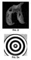
- FIG. 2is a color reproduction of a three-dimensional thickness map of the articular cartilage of the distal femur.
- Three-dimensional thickness mapscan be generated, for example, from ultrasound, CT or MRI data. Dark holes within the substances of the cartilage indicate areas of full thickness cartilage loss.
- FIG. 3Ashows an example of a Placido disc of concentrically arranged circles of light.
- FIG. 3Bshows an example of a projected Placido disc on a surface of fixed curvature.
- FIG. 4shows a reflection resulting from a projection of concentric circles of light (Placido Disk) on each femoral condyle, demonstrating the effect of variation in surface contour on the reflected circles.
- FIG. 5shows an example of a 2D color-coded topographical map of an irregularly curved surface.
- FIG. 6shows an example of a 3D color-coded topographical map of an irregularly curved surface.
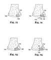
- FIGS. 7A-Hillustrate, in cross-section, various stages of knee resurfacing.
- FIG. 7Ashows an example of normal thickness cartilage and a cartilage defect.
- FIG. 7Bshows an imaging technique or a mechanical, optical, laser or ultrasound device measuring the thickness and detecting a sudden change in thickness indicating the margins of a cartilage defect.
- FIG. 7Cshows a weight-bearing surface mapped onto the articular cartilage.
- FIG. 7Dshows an intended implantation site and cartilage defect.
- FIG. 7Edepicts placement of an exemplary single component articular surface repair system.
- FIG. 7Fshows an exemplary multi-component articular surface repair system.
- FIG. 7Gshows an exemplary single component articular surface repair system.
- FIG. 7Hshows an exemplary multi-component articular surface repair system.
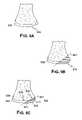
- FIGS. 8A-Eillustrate, in cross-section, exemplary knee imaging and resurfacing.
- FIG. 8Ashows a magnified view of an area of diseased cartilage.
- FIG. 8Bshows a measurement of cartilage thickness adjacent to the defect.
- FIG. 8Cdepicts placement of a multi-component mini-prosthesis for articular resurfacing.
- FIG. 8Dis a schematic depicting placement of a single component mini-prosthesis utilizing stems or pegs.
- FIG. 8Edepicts placement of a single component mini-prosthesis utilizing stems and an opening for injection of bone cement.
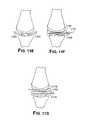
- FIGS. 9A-Cillustrate, in cross-section, other exemplary knee resurfacing devices and methods.
- FIG. 9Adepicts normal thickness cartilage in the anterior and central and posterior portion of a femoral condyle and a large area of diseased cartilage in the posterior portion of the femoral condyle.
- FIG. 9Bdepicts placement of a single component articular surface repair system.
- FIG. 9Cdepicts a multi-component articular surface repair system.
- FIGS. 10A-Bare flow charts illustrating steps for forming a device in situ.
- FIGS. 11A-Gillustrate, in cross-section, the use of an inflation device to form an implant.
- FIG. 11Aillustrates a single lumen balloon inserted between two joint surfaces where the inflation occurs within the bounds of the joint.
- FIG. 11Billustrates another single lumen balloon inserted between two joint surfaces where the inflatable surfaces extend beyond a first and second edge of a joint.
- FIG. 11Cillustrates another single lumen balloon between two joint surfaces.
- FIG. 11Dillustrates a multi-balloon solution using two balloons where the balloons are adjacent to each other within the joint.
- FIG. 11Eillustrates an alternative multi-balloon solution wherein a first balloon is comprised within a second balloon.
- FIG. 11Aillustrates a single lumen balloon inserted between two joint surfaces where the inflation occurs within the bounds of the joint.
- FIG. 11Billustrates another single lumen balloon inserted between two joint surfaces where the inflatable surfaces extend beyond a first and second edge of a joint.
- FIG. 11Cillustrates another single lume
- FIG. 11Fillustrates another multi-balloon solution where a first balloon lies within the lumen of a second balloon and further wherein the second balloon is adjacent a third balloon.
- FIG. 11Gillustrates a 3 balloon configuration wherein a first balloon lies adjacent a second balloon and a third balloon fits within the lumen of one of the first or second balloon.
- FIGS. 12A-Eillustrate a variety of cross-sectional shapes achieved using balloons with variable wall thicknesses or material compositions.
- the inflation deviceenables the implant to achieve a surface conforming to the irregularities of the joint surface.
- the inflation deviceenables the implant to achieve a surface that sits above the irregular joint surface;
- FIG. 12Cillustrates a device formed where a central portion of the device sits above the joint surface irregularities while the proximal and distal ends illustrated form a lateral abutting surface to the joint defects.
- FIG. 12Dillustrates a device formed using a first inflation device within a second inflation device, with an exterior configuration similar to that shown in FIG. 12A ; while FIG. 12E illustrates an alternative device formed using at least two different inflation devices having an exterior shape similar to the device shown in FIG. 12C .
- FIGS. 13 A-J( 1 - 3 )show a variety of cross-sectional views of the inflation devices shown in FIGS. 11 and 12 taken at a position perpendicular to the views shown in FIGS. 11 and 12 .
- FIGS. 14A-Jillustrate the use of a retaining device to form an implant in situ.
- FIGS. 15A-Bshow single and multiple component devices.
- FIG. 15Ashows an exemplary single component articular surface repair system with varying curvature and radii.
- FIG. 15Bdepicts a multi-component articular surface repair system with a second component that mirrors the shape of the subchondral bone and a first component closely matches the shape and curvature of the surrounding normal cartilage.
- FIGS. 16A-Bshow exemplary articular repair systems having an outer contour matching the surrounding normal cartilage.
- the systemsare implanted into the underlying bone using one or more pegs.
- FIG. 17shows a perspective view of an exemplary articular repair device including a flat surface to control depth and prevent toggle; an exterior surface having the contour of normal cartilage; flanges to prevent rotation and control toggle; a groove to facilitate tissue in-growth.
- FIGS. 18A-Ddepict, in cross-section, another example of an implant with multiple anchoring pegs.
- FIG. 18B-Dshow various cross-sectional representations of the pegs: FIG. 18B shows a peg having a groove; FIG. 18C shows a peg with radially-extending arms that help anchor the device in the underlying bone; and FIG. 18D shows a peg with multiple grooves or flanges.
- FIG. 19A-Bdepict an overhead view of an exemplary implant with multiple anchoring pegs and depict how the pegs are not necessarily linearly aligned along the longitudinal axis of the device.
- FIGS. 20A-Edepict an exemplary implant having radially extending arms.
- FIGS. 20B-Eare overhead views of the implant showing that the shape of the peg need not be conical.
- FIG. 21Aillustrates a femur, tibia and fibula along with the mechanical and anatomic axes.
- FIGS. 21B-Eillustrate the tibia with the anatomic and mechanical axis used to create a cutting plane along with a cut femur and tibia.
- FIG. 21Fillustrates the proximal end of the femur including the head of the femur.
- FIG. 22shows an example of a surgical tool having one surface matching the geometry of an articular surface of the joint. Also shown is an aperture in the tool capable of controlling drill depth and width of the hole and allowing implantation of an insertion of implant having a press-fit design.
- FIG. 23is a flow chart depicting various methods of the invention used to create a mold for preparing a patient's joint for arthroscopic surgery.
- FIG. 24Adepicts, in cross-section, an example of a surgical tool containing an aperture through which a surgical drill or saw can fit.
- the apertureguides the drill or saw to make the proper hole or cut in the underlying bone.
- Dotted linesrepresent where the cut corresponding to the aperture will be made in bone.
- FIG. 24Bdepicts, in cross-section, an example of a surgical tool containing apertures through which a surgical drill or saw can fit and which guide the drill or saw to make cuts or holes in the bone. Dotted lines represent where the cuts corresponding to the apertures will be made in bone.
- FIGS. 25A-Qillustrate tibial cutting blocks and molds used to create a surface perpendicular to the anatomic axis for receiving the tibial portion of a knee implant.
- FIGS. 26A-Oillustrate femur cutting blocks and molds used to create a surface for receiving the femoral portion of a knee implant.
- FIG. 27A-Gillustrate patellar cutting blocks and molds used to prepare the patella for receiving a portion of a knee implant.
- FIG. 28A-Hillustrate femoral head cutting blocks and molds used to create a surface for receiving the femoral portion of a knee implant.
- FIG. 29A-Dillustrate acetabulum cutting blocks and molds used to create a surface for a hip implant.
- the practice of the present inventionemploys, unless otherwise indicated, conventional methods of x-ray imaging and processing, x-ray tomosynthesis, ultrasound including A-scan, B-scan and C-scan, computed tomography (CT scan), magnetic resonance imaging (MRI), optical coherence tomography, single photon emission tomography (SPECT) and positron emission tomography (PET) within the skill of the art.
- CT scancomputed tomography
- MRImagnetic resonance imaging
- SPECTsingle photon emission tomography
- PETpositron emission tomography
- the present inventionprovides methods and compositions for repairing joints, particularly for repairing articular cartilage and for facilitating the integration of a wide variety of cartilage repair materials into a subject.
- the techniques described hereinallow for the customization of cartilage repair material to suit a particular subject, for example in terms of size, cartilage thickness and/or curvature.
- shapee.g., size, thickness and/or curvature
- the success of repairis enhanced.
- the repair materialcan be shaped prior to implantation and such shaping can be based, for example, on electronic images that provide information regarding curvature or thickness of any “normal” cartilage surrounding the defect and/or on curvature of the bone underlying the defect.
- the current inventionprovides, among other things, for minimally invasive methods for partial joint replacement. The methods will require only minimal or, in some instances, no loss in bone stock. Additionally, unlike with current techniques, the methods described herein will help to restore the integrity of the articular surface by achieving an exact or near anatomic match between the implant and the surrounding or adjacent cartilage and/or subchondral bone.
- Advantages of the present inventioncan include, but are not limited to, (i) customization of joint repair, thereby enhancing the efficacy and comfort level for the patient following the repair procedure; (ii) eliminating the need for a surgeon to measure the defect to be repaired intraoperatively in some embodiments; (iii) eliminating the need for a surgeon to shape the material during the implantation procedure; (iv) providing methods of evaluating curvature of the repair material based on bone or tissue images or based on intraoperative probing techniques; (v) providing methods of repairing joints with only minimal or, in some instances, no loss in bone stock; and (vi) improving postoperative joint congruity.
- the methods described hereinallow for the design and use of joint repair material that more precisely fits the defect (e.g., site of implantation) and, accordingly, provides improved repair of the joint.
- the methods and compositions described hereincan be used to treat defects resulting from disease of the cartilage (e.g., osteoarthritis), bone damage, cartilage damage, trauma, and/or degeneration due to overuse or age.
- the inventionallows, among other things, a health practitioner to evaluate and treat such defects.
- the size, volume and shape of the area of interestcan include only the region of cartilage that has the defect, but preferably will also include contiguous parts of the cartilage surrounding the cartilage defect.
- size, curvature and/or thickness measurementscan be obtained using any suitable technique.
- one-dimensional, two-dimensional, and/or three-dimensional measurementscan be obtained using suitable mechanical means, laser devices, electromagnetic or optical tracking systems, molds, materials applied to the articular surface that harden and “memorize the surface contour,” and/or one or more imaging techniques known in the art. Measurements can be obtained non-invasively and/or intraoperatively (e.g., using a probe or other surgical device).
- the thickness of the repair devicecan vary at any given point depending upon the depth of the damage to the cartilage and/or bone to be corrected at any particular location on an articular surface.
- the processbegins by first measuring the size of the area of diseased cartilage or cartilage loss 10 . Thereafter the user can optionally measure the thickness of adjacent cartilage 20 . Once these steps are performed, the curvature of the articular surface is measured 30 . Alternatively, the curvature of subchondral bone can be measured.
- an implantcan be selected from a library 32 or an implant can be generated based on the patient specific parameters obtained in the measurements and evaluation 34 .
- the implantation siteis prepared 40 and then the implant is installed 42 .
- One or more of these stepscan be repeated as necessary or desired as shown by the optional repeat steps 11 , 21 , 31 , 33 , 35 , and 41 .
- imaging techniques suitable for measuring thickness and/or curvature (e.g., of cartilage and/or bone) or size of areas of diseased cartilage or cartilage lossinclude the use of x-rays, magnetic resonance imaging (MRI), computed tomography scanning (CT, also known as computerized axial tomography or CAT), optical coherence tomography, ultrasound imaging techniques, and optical imaging techniques.
- MRImagnetic resonance imaging
- CTcomputed tomography scanning
- CATcomputerized axial tomography
- optical coherence tomographyoptical coherence tomography
- ultrasound imaging techniquesand optical imaging techniques.
- Contrast or other enhancing agentscan be employed using any route of administration, e.g. intravenous, intra-articular, etc.
- CT or MRIis used to assess tissue, bone, cartilage and any defects therein, for example cartilage lesions or areas of diseased cartilage, to obtain information on subchondral bone or cartilage degeneration and to provide morphologic or biochemical or biomechanical information about the area of damage.
- changessuch as fissuring, partial or full thickness cartilage loss, and signal changes within residual cartilage can be detected using one or more of these methods.
- MRIincluding conventional T1 and T2-weighted spin-echo imaging, gradient recalled echo (GRE) imaging, magnetization transfer contrast (MTC) imaging, fast spin-echo (FSE) imaging, contrast enhanced imaging, rapid acquisition relaxation enhancement (RARE) imaging, gradient echo acquisition in the steady state (GRASS), and driven equilibrium Fourier transform (DEFT) imaging, to obtain information on cartilage, see Alexander, et al., WO 02/22014.
- GREgradient recalled echo
- MTCmagnetization transfer contrast
- FSEfast spin-echo
- RARErapid acquisition relaxation enhancement
- GASSgradient echo acquisition in the steady state
- DEFTdriven equilibrium Fourier transform
- the measurements producedare based on three-dimensional images of the joint obtained as described in Alexander, et al., WO 02/22014 or sets of two-dimensional images ultimately yielding 3D information.
- Two-dimensional, and three-dimensional images, or maps, of the cartilage alone or in combination with a movement pattern of the joint, e.g. flexion—extension, translation and/or rotation,can be obtained.
- Three-dimensional imagescan include information on movement patterns, contact points, contact zone of two or more opposing articular surfaces, and movement of the contact point or zone during joint motion.
- Two- and three-dimensional imagescan include information on biochemical composition of the articular cartilage.
- imaging techniquescan be compared over time, for example to provide up-to-date information on the shape and type of repair material needed.
- imaging techniquescan be combined, if desired.
- C-arm imaging or x-ray fluoroscopycan be used for motion imaging, while MRI can yield high resolution cartilage information.
- C-arm imagingcan be combined with intra-articular contrast to visualize the cartilage.
- FIG. 2illustrates a color reproduction of a three-dimensional thickness map of the articular surface on the distal femur.
- the dark holes within the cartilageindicate areas of full cartilage loss.
- Imagingcan be used to determine the anatomical and biomechanical axes of an extremity associated with a joint. Suitable tests include, for example, an x-ray, or an x-ray combined with an MRI. Typically, anatomical landmarks are identified on the imaging test results (e.g., the x-ray film) and those landmarks are then utilized to directly or indirectly determine the desired axes. Thus, for example, if surgery is contemplated in a hip joint, knee joint, or ankle joint, an x-ray can be obtained. This x-ray can be a weight-bearing film of the extremity, for example, a full-length leg film taken while the patient is standing.
- This filmcan be used to determine the femoral and tibial anatomical axes and to estimate the biomechanical axes.
- these processes for identifying, e.g., anatomical and biomechanical axis of the jointcan be applied to other joints without departing from the scope of the invention.
- Anatomical and biomechanical axescan also be determined using other imaging modalities, including but not limited to, computed tomography and MRI.
- a CT scancan be obtained through the hip joint, the knee joint, and the ankle joint.
- the scancan be reformatted in the sagittal, coronal, or other planes.
- the CT imagescan then be utilized to identify anatomical landmarks and to determine the anatomical and biomechanical axes of the hip joint, knee joint, and/or ankle joint.
- an MRI scancan be obtained for this purpose.
- an MRI scan of the thigh and pelvic regioncan be obtained using a body coil or a torso phased array coil.
- a high resolution scan of the knee jointcan be obtained using a dedicated extremity coil.
- a scan of the calf/tibia region and the ankle jointcan be obtained again using a body coil or a torso phased array coil.
- Anatomical landmarkscan be identified in each joint on these scans and the anatomical and biomechanical axes can be estimated using this information.
- An imaging test obtained during weight-bearing conditionshas some inherent advantages, in that it demonstrates normal as well as pathological loading and load distribution.
- a cross-sectional imaging study such as a CT scan or MRI scanhas some advantages because it allows one to visualize and demonstrate the anatomical landmarks in three, rather than two, dimensions, thereby adding accuracy.
- measurementscan be performed in other planes, such as the sagittal or oblique planes, that may not be easily accessible in certain anatomical regions using conventional radiography. In principle, any imaging test can be utilized for this purpose.
- the biomechanical axiscan be defined as the axis going from the center of the femoral head, between the condylar surfaces and through the ankle joint.
- Computed Tomography imaginghas been shown to be highly accurate for the determination of the relative anatomical and biomechanical axes of the leg (Testi Debora, Zannoni Cinzia, Cappello Angelo and Viceconti Marco. “Border tracing algorithm implementation for the femoral geometry reconstruction.” Comp. Meth. and Programs in Biomed. , Feb. 14, 2000; Farrar M J, Newman R J, Mawhinney R R, King R. “Computed tomography scan scout film for measurement of femoral axis in knee arthroplasty.” J. Arthroplasty . December 1999; 14(8): 1030-1; Kim J S, Park T S, Park S B, Kim J S, Kim I Y, Kim S I.
- angles of the anatomical structures of the proximal and distal femuralso show a certain variability level (i.e. standard deviation) comparable with the varus or valgus angle or the angle between the anatomical femoral axis and the biomechanical axis (Mahaisavariya B, Sitthiseripratip K, Tongdee T, Bohez E, Sloten J V, Oris P. “Morphological study of the proximal femur: a new method of geometrical assessment using 3 dimensional reverse engineering.” Med. Eng. and Phys. 24 (2002) 617-622).
- a preferred approach for assessing the axesis based on CT scans of the hip, knee and ankle joint or femur rather than only of the knee region.
- CThas been shown to be efficient in terms of the contrast of the bone tissue with respect to surrounding anatomical tissue so the bone structures corresponding to the femur and tibia can be extracted very accurately with semi automated computerized systems (Mahaisavariya B, Sitthiseripratip K, Tongdee T, Bohez E, Sloten J V, Oris P. “Morphological study of the proximal femur: a new method of geometrical assessment using 3 dimensional reverse engineering.” Med. Eng. and Phys. 24 (2002) 617-622; Testi Debora, Zannoni Cinzia, Cappello Angelo and Viceconti Marco. “Border tracing algorithm implementation for the femoral geometry reconstruction.” Comp. Meth. and Programs in Biomed. , Feb. 14, 2000).
- Part 13D imaging method. Medical and Biological engineering and computing. 38(6): 603-609, November 2000; Kim J S, Park T S, Park S B, Kim J S, Kim I Y, Kim S I. Measurement of femoral neck anteversion in 3D.
- Part 13D modeling method. Medical and Biological engineering and computing. 38(6): 610-616, November 2000).
- Farrarused simple CT 2-D scout views to estimate the femoral axis (Farrar M J, Newman R J, Mawhinney R R, King R. Computed tomography scan scout film for measurement of femoral axis in knee arthroplasty. J. Arthroplasty. December 1999; 14(8): 1030-1).
- 2-D sagittal and coronal reconstructions of CT slice imagesare used to manually estimate the biomechanical axis.
- One skilled in the artcan easily recognize many different ways to automate this process. For example, a CT scan covering at least the hip, knee and ankle region is acquired. This results in image slices (axial) which can be interpolated to generate the sagittal and coronal views.
- Preprocessing (filtering) of the slice imagescan be used to improve the contrast of the bone regions so that they can be extracted accurately using simple thresholding or a more involved image segmentation tool like LiveWire or active contour models.
- the biomechanical axiscan be defined as the line connecting the proximal and the distal centroids, i.e. the femoral head centroid, the tibial or ankle joint centroid.
- the position of the intercondylar notchcan be used for evaluation of possible deviations, errors or deformations including varus and valgus deformity.
- multiple imaging testscan be combined.
- the anatomical and biomechanical axescan be estimated using a weight-bearing x-ray of the extremity or portions of the extremity.
- the anatomical information derived in this fashioncan then be combined with a CT or MRI scan of one or more joints, such as a hip, knee, or ankle joint.
- Landmarks seen on radiographycan then, for example, be cross-referenced on the CT or MRI scan.
- Axis measurements performed on radiographycan be subsequently applied to the CT or MRI scans or other imaging modalities.
- the information obtained from a CT scancan be compared with that obtained with an MRI or ultrasound scan.
- image fusion of different imaging modalitiescan be performed.
- a full-length weight-bearing x-ray of the lower extremitycan be obtained.
- Thiscan be supplemented by a spiral CT scan, optionally with intra-articular contrast of the knee joint providing high resolution three-dimensional anatomical characterization of the knee anatomy even including the menisci and cartilage.
- This information, along with the axis information provided by the radiographcan be utilized to select or derive therapies, such as implants or surgical instruments.
- a CT scanpreferably a spiral CT scan of one or more joints.
- the spiral CT scancan optionally be performed using intra-articular contrast.
- an MRI scancan be performed. If CT is utilized, a full spiral scan, or a few selected slices, can be obtained through neighboring joints. Typically, a full spiral scan providing full three-dimensional characterization would be obtained in the joint for which therapy is contemplated. If implants, or molds, for surgical instruments are selected or shaped, using this scan, the subchondral bone shape can be accurately determined from the resultant image data.
- a standard cartilage thickness and, similarly, a standard cartilage losscan be assumed in certain regions of the articular surface.
- a standard thickness of 2 mm of the articular cartilagecan be applied to the subchondral bone in the anterior third of the medial and lateral femoral condyles.
- a standard thickness of 2 mm of the articular cartilagecan be applied to the subchondral bone in the posterior third of the medial and lateral femoral condyles.
- a standard thickness of 0 mm of the articular cartilagecan be applied in the central weight-bearing zone of the medial condyle, and a different value can be applied to the lateral condyle.
- the transition between these zonescan be gradual, for example, from 2 mm to 0 mm.
- These standard values of estimated cartilage thickness and cartilage loss in different regions of the jointcan optionally be derived from a reference database.
- the reference databasecan include categories such as age, body mass index (“BMI”), severity of disease, pain, severity of varus deformity, severity of valgus deformity, Kellgren-Lawrence score, along with other parameters that are determined to be relative and useful.
- BMIbody mass index
- Use of a standard thickness for the articular cartilagecan facilitate the imaging protocols required for pre-operative planning.
- the articular cartilagecan be fully characterized by performing a spiral CT scan of the joint in the presence of intra-articular contrast or by performing an MRI scan using cartilage sensitive pulse sequences.
- the techniques described hereincan be used to obtain an image of a joint that is stationary, either weight bearing or not, or in motion or combinations thereof. Imaging studies that are obtained during joint motion can be useful for assessing the load bearing surface. This can be advantageous for designing or selecting implants, e.g. for selecting reinforcements in high load areas, for surgical tools and for implant placement, e.g. for optimizing implant alignment relative to high load areas.
- measurements of the size of an area of diseased cartilage or an area of cartilage loss, measurements of cartilage thickness and/or curvature of cartilage or bonecan be obtained intraoperatively during arthroscopy or open arthrotomy. Intraoperative measurements can, but need not, involve actual contact with one or more areas of the articular surfaces.
- Devices suitable for obtaining intraoperative measurements of cartilage or bone or other articular structures, and to generate a topographical map of the surfaceinclude but are not limited to, Placido disks and laser interferometers, and/or deformable materials or devices.
- Placido disks and laser interferometersSee, for example, U.S. Pat. No. 6,382,028 to Wooh et al., issued May 7, 2002; U.S. Pat. No. 6,057,927 to Levesque et al., issued May 2, 2000; U.S. Pat. No. 5,523,843 to Yamane et al. issued Jun. 4, 1996; U.S. Pat. No. 5,847,804 to Sarver et al. issued Dec. 8, 1998; and U.S. Pat. No. 5,684,562 to Fujieda, issued Nov. 4, 1997).
- FIG. 3Aillustrates a Placido disk of concentrically arranged circles of light.
- the concentric arrays of the Placido diskproject well-defined circles of light of varying radii, generated either with laser or white light transported via optical fiber.
- the Placido diskcan be attached to the end of an endoscopic device (or to any probe, for example a hand-held probe) so that the circles of light are projected onto the cartilage surface.
- FIG. 3Billustrates an example of a Placido disk projected onto the surface of a fixed curvature.
- One or more imaging camerascan be used (e.g., attached to the device) to capture the reflection of the circles.
- Mathematical analysisis used to determine the surface curvature.
- the curvaturecan then, for example, be visualized on a monitor as a color-coded, topographical map of the cartilage surface. Additionally, a mathematical model of the topographical map can be used to determine the ideal surface topography to replace any cartilage defects in the area analyzed.
- FIG. 4shows a reflection resulting from the projection of concentric circles of light (Placido disk) on each femoral condyle, demonstrating the effect of variation in surface contour on reflected circles.
- a laser interferometercan also be attached to the end of an endoscopic device.
- a small sensorcan be attached to the device in order to determine the cartilage surface or bone curvature using phase shift interferometry, producing a fringe pattern analysis phase map (wave front) visualization of the cartilage surface.
- the curvaturecan then be visualized on a monitor as a color coded, topographical map of the cartilage surface.
- a mathematical model of the topographical mapcan be used to determine the ideal surface topography to replace any cartilage or bone defects in the area analyzed. This computed, ideal surface, or surfaces, can then be visualized on the monitor, and can be used to select the curvature, or curvatures, of the replacement cartilage.
- Mechanical devicescan also be used for intraoperative measurements, for example, deformable materials such as gels, molds, any hardening materials (e.g., materials that remain deformable until they are heated, cooled, or otherwise manipulated).
- deformable materialssuch as gels, molds, any hardening materials (e.g., materials that remain deformable until they are heated, cooled, or otherwise manipulated).
- a deformable gelcan be applied to a femoral condyle. The side of the gel pointing towards the condyle can yield a negative impression of the surface contour of the condyle. The negative impression can then be used to determine the size of a defect, the depth of a defect and the curvature of the articular surface in and adjacent to a defect.
- This informationcan be used to select a therapy, e.g. an articular surface repair system.
- a hardening materialcan be applied to an articular surface, e.g. a femoral condyle or a tibial plateau. The hardening material can remain on the articular surface until hardening has occurred. The hardening material can then be removed from the articular surface. The side of the hardening material pointing towards the articular surface can yield a negative impression of the articular surface. The negative impression can then be used to determine the size of a defect, the depth of a defect and the curvature of the articular surface in and adjacent to a defect.
- This informationcan then be used to select a therapy, e.g. an articular surface repair system.
- the hardening systemcan remain in place and form the actual articular surface repair system.
- the deformable materialcomprises a plurality of individually moveable mechanical elements.
- each elementWhen pressed against the surface of interest, each element can be pushed in the opposing direction and the extent to which it is pushed (deformed) can correspond to the curvature of the surface of interest.
- the devicecan include a brake mechanism so that the elements are maintained in the position that conforms to the surface of the cartilage and/or bone. The device can then be removed from the patient and analyzed for curvature.
- each individual moveable elementcan include markers indicating the amount and/or degree it is deformed at a given spot.
- a cameracan be used to intra-operatively image the device and the image can be saved and analyzed for curvature information. Suitable markers include, but are not limited to, actual linear measurements (metric or empirical), different colors corresponding to different amounts of deformation and/or different shades or hues of the same color(s). Displacement of the moveable elements can also be measured using electronic means.
- Other devices to measure cartilage and subchondral bone intraoperativelyinclude, for example, ultrasound probes.
- An ultrasound probepreferably handheld, can be applied to the cartilage and the curvature of the cartilage and/or the subchondral bone can be measured. Moreover, the size of a cartilage defect can be assessed and the thickness of the articular cartilage can be determined.
- Such ultrasound measurementscan be obtained in A-mode, B-mode, or C-mode. If A-mode measurements are obtained, an operator can typically repeat the measurements with several different probe orientations, e.g. mediolateral and anteroposterior, in order to derive a three-dimensional assessment of size, curvature and thickness.
- the probesare preferably handheld.
- the probes or at least a portion of the probe, typically the portion that is in contact with the tissuecan be sterile. Sterility can be achieved with use of sterile covers, for example similar to those disclosed in WO 99/08598A1 to Lang, published Feb. 25, 1999.
- Analysis on the curvature of the articular cartilage or subchondral bone using imaging tests and/or intraoperative measurementscan be used to determine the size of an area of diseased cartilage or cartilage loss.
- the curvaturecan change abruptly in areas of cartilage loss.
- Such abrupt or sudden changes in curvaturecan be used to detect the boundaries of diseased cartilage or cartilage defects.
- measurementscan be made while the joint is stationary, either weight bearing or not, or in motion.
- a wide variety of materialsfind use in the practice of the present invention, including, but not limited to, plastics, metals, crystal free metals, ceramics, biological materials (e.g., collagen or other extracellular matrix materials), hydroxyapatite, cells (e.g., stem cells, chondrocyte cells or the like), or combinations thereof.
- a repair materialcan be formed or selected. Further, using one or more of these techniques described herein, a cartilage replacement or regenerating material having a curvature that will fit into a particular cartilage defect, will follow the contour and shape of the articular surface, and will match the thickness of the surrounding cartilage.
- the repair materialcan include any combination of materials, and typically include at least one non-pliable material, for example materials that are not easily bent or changed.
- joint repair systemsoften employ metal and/or polymeric materials including, for example, prostheses which are anchored into the underlying bone (e.g., a femur in the case of a knee prosthesis).
- metal and/or polymeric materialsincluding, for example, prostheses which are anchored into the underlying bone (e.g., a femur in the case of a knee prosthesis).
- a femurin the case of a knee prosthesis.
- a wide-variety of metalsare useful in the practice of the present invention, and can be selected based on any criteria. For example, material selection can be based on resiliency to impart a desired degree of rigidity.
- Non-limiting examples of suitable metalsinclude silver, gold, platinum, palladium, iridium, copper, tin, lead, antimony, bismuth, zinc, titanium, cobalt, stainless steel, nickel, iron alloys, cobalt alloys, such as Elgiloy®, a cobalt-chromium-nickel alloy, and MP35N, a nickel-cobalt-chromium-molybdenum alloy, and NitinolTM, a nickel-titanium alloy, aluminum, manganese, iron, tantalum, crystal free metals, such as Liquidmetal® alloys (available from LiquidMetal Technologies, www.liquidmetal.com), other metals that can slowly form polyvalent metal ions, for example to inhibit calcification of implanted substrates in contact with a patient's bodily fluids or tissues, and combinations thereof.
- suitable metalsinclude silver, gold, platinum, palladium, iridium, copper, tin, lead, antimony, bismuth, zinc
- Suitable synthetic polymersinclude, without limitation, polyamides (e.g., nylon), polyesters, polystyrenes, polyacrylates, vinyl polymers (e.g., polyethylene, polytetrafluoroethylene, polypropylene and polyvinyl chloride), polycarbonates, polyurethanes, poly dimethyl siloxanes, cellulose acetates, polymethyl methacrylates, polyether ether ketones, ethylene vinyl acetates, polysulfones, nitrocelluloses, similar copolymers and mixtures thereof.
- polyamidese.g., nylon
- polyesterse.g., polystyrenes
- polyacrylatese.g., polyethylene, polytetrafluoroethylene, polypropylene and polyvinyl chloride
- polycarbonatese.g., polycarbonates, polyurethanes, poly dimethyl siloxanes, cellulose acetates, polymethyl methacrylates, polyether ether ketones, ethylene vinyl a
- Bioresorbable synthetic polymerscan also be used such as dextran, hydroxyethyl starch, derivatives of gelatin, polyvinylpyrrolidone, polyvinyl alcohol, poly[N-(2-hydroxypropyl)methacrylamide], poly(hydroxy acids), poly(epsilon-caprolactone), polylactic acid, polyglycolic acid, poly(dimethyl glycolic acid), poly(hydroxy butyrate), and similar copolymers can also be used.
- PEEKTMpolyetheretherketone
- PEEK 450Gis an unfilled PEEK approved for medical implantation available from Victrex of Lancashire, Great Britain.
- Victrexis located at www.matweb.com or see Boedeker www.boedeker.com).
- Other sources of this materialinclude Gharda located in Panoli, India (www.ghardapolymers.com).
- the material selectedcan also be filled.
- other grades of PEEKare also available and contemplated, such as 30% glass-filled or 30% carbon filled, provided such materials are cleared for use in implantable devices by the FDA, or other regulatory body.
- Glass filled PEEKreduces the expansion rate and increases the flexural modulus of PEEK relative to that portion which is unfilled.
- the resulting productis known to be ideal for improved strength, stiffness, or stability.
- Carbon filled PEEKis known to enhance the compressive strength and stiffness of PEEK and lower its expansion rate. Carbon filled PEEK offers wear resistance and load carrying capability.
- thermoplastic or thermoplastic polycondensate materialsthat resist fatigue, have good memory, are flexible, and/or deflectable have very low moisture absorption, and good wear and/or abrasion resistance, can be used without departing from the scope of the invention.
- the implantcan also be comprised of polyetherketoneketone (PEKK).
- PEKpolyetherketone
- PEKEKKpolyetherketoneetherketoneketone
- PEEKKpolyetherketoneketone
- the polymerscan be prepared by any of a variety of approaches including conventional polymer processing methods.
- Preferred approachesinclude, for example, injection molding, which is suitable for the production of polymer components with significant-structural features, and rapid prototyping approaches, such as reaction injection molding and stereo-lithography.
- the substratecan be textured or made porous by either physical abrasion or chemical alteration to facilitate incorporation of the metal coating. Other processes are also appropriate, such as extrusion, injection, compression molding and/or machining techniques.
- the polymeris chosen for its physical and mechanical properties and is suitable for carrying and spreading the physical load between the joint surfaces.
- More than one metal and/or polymercan be used in combination with each other.
- one or more metal-containing substratescan be coated with polymers in one or more regions or, alternatively, one or more polymer-containing substrate can be coated in one or more regions with one or more metals.
- the system or prosthesiscan be porous or porous coated.
- the porous surface componentscan be made of various materials including metals, ceramics, and polymers. These surface components can, in turn, be secured by various means to a multitude of structural cores formed of various metals.
- Suitable porous coatingsinclude, but are not limited to, metal, ceramic, polymeric (e.g., biologically neutral elastomers such as silicone rubber, polyethylene terephthalate and/or combinations thereof or combinations thereof. See, e.g., U.S. Pat. No. 3,605,123 to Hahn, issued Sep. 20, 1971. U.S. Pat. No. 3,808,606 to Tronzo issued May 7, 1974 and U.S. Pat. No. 3,843,975 to Tronzo issued Oct.
- the coatingcan be applied by surrounding a core with powdered polymer and heating until cured to form a coating with an internal network of interconnected pores.
- the tortuosity of the porese.g., a measure of length to diameter of the paths through the pores
- the porous coatingcan be applied in the form of a powder and the article as a whole subjected to an elevated temperature that bonds the powder to the substrate. Selection of suitable polymers-and/or powder coatings can be determined in view of the teachings and references cited herein, for example based on the melt index of each.
- Repair materialscan also include one or more biological material either alone or in combination with non-biological materials.
- any base materialcan be designed or shaped and suitable cartilage replacement or regenerating material(s) such as fetal cartilage cells can be applied to be the base.
- the cellscan be then be grown in conjunction with the base until the thickness (and/or curvature) of the cartilage surrounding the cartilage defect has been reached.
- Conditions for growing cellse.g., chondrocytes
- various substrates in culture, ex vivo and in vivoare described, for example, in U.S. Pat. Nos. 5,478,739 to Slivka et al. issued Dec. 26, 1995; U.S. Pat. No. 5,842,477 to Naughton et al.
- suitable substratesinclude plastic, tissue scaffold, a bone replacement material (e.g., a hydroxyapatite, a bioresorbable material), or any other material suitable for growing a cartilage replacement or regenerating material on it.
- a bone replacement materiale.g., a hydroxyapatite, a bioresorbable material
- Bio polymerscan be naturally occurring or produced in vitro by fermentation and the like. Suitable biological polymers include, without limitation, collagen, elastin, silk, keratin, gelatin, polyamino acids, cat gut sutures, polysaccharides (e.g., cellulose and starch) and mixtures thereof. Biological polymers can be bioresorbable.
- Biological materials used in the methods described hereincan be autografts (from the same subject); allografts (from another individual of the same species) and/or xenografts (from another species). See, also, International Patent Publications WO 02/22014 to Alexander et al. published Mar. 21, 2002 and WO 97/27885 to Lee published Aug. 7, 1997.
- autologous materialsare preferred, as they can carry a reduced risk of immunological complications to the host, including re-absorption of the materials, inflammation and/or scarring of the tissues surrounding the implant site.
- a probeis used to harvest tissue from a donor site and to prepare a recipient site.
- the donor sitecan be located in a xenograft, an allograft or an autograft.
- the probeis used to achieve a good anatomic match between the donor tissue sample and the recipient site.
- the probeis specifically designed to achieve a seamless or near seamless match between the donor tissue sample and the recipient site.
- the probecan, for example, be cylindrical.
- the distal end of the probeis typically sharp in order to facilitate tissue penetration. Additionally, the distal end of the probe is typically hollow in order to accept the tissue.
- the probecan have an edge at a defined distance from its distal end, e.g.
- the edgecan be external or can be inside the hollow portion of the probe.
- an orthopedic surgeoncan take the probe and advance it with physical pressure into the cartilage, the subchondral bone and the underlying marrow in the case of a joint such as a knee joint. The surgeon can advance the probe until the external or internal edge reaches the cartilage surface. At that point, the edge will prevent further tissue penetration thereby achieving a constant and reproducible tissue penetration.
- the distal end of the probecan include one or more blades, saw-like structures, or tissue cutting mechanism.
- the distal end of the probecan include an iris-like mechanism consisting of several small blades.
- the blade or bladescan be moved using a manual, motorized or electrical mechanism thereby cutting through the tissue and separating the tissue sample from the underlying tissue. Typically, this will be repeated in the donor and the recipient. In the case of an iris-shaped blade mechanism, the individual blades can be moved so as to close the iris thereby separating the tissue sample from the donor site.
- a laser device or a radiofrequency devicecan be integrated inside the distal end of the probe.
- the laser device or the radiofrequency devicecan be used to cut through the tissue and to separate the tissue sample from the underlying tissue.
- the same probecan be used in the donor and in the recipient.
- similarly shaped probes of slightly different physical dimensionscan be used.
- the probe used in the recipientcan be slightly smaller than that used in the donor thereby achieving a tight fit between the tissue sample or tissue transplant and the recipient site.
- the probe used in the recipientcan also be slightly shorter than that used in the donor thereby correcting for any tissue lost during the separation or cutting of the tissue sample from the underlying tissue in the donor material.
- Any biological repair materialcan be sterilized to inactivate biological contaminants such as bacteria, viruses, yeasts, molds, mycoplasmas and parasites. Sterilization can be performed using any suitable technique, for example radiation, such as gamma radiation.
- Any of the biological materials described hereincan be harvested with use of a robotic device.
- the robotic devicecan use information from an electronic image for tissue harvesting.
- the cartilage replacement materialhas a particular biochemical composition.
- the biochemical composition of the cartilage surrounding a defectcan be assessed by taking tissue samples and chemical analysis or by imaging techniques.
- WO 02/22014 to Alexanderdescribes the use of gadolinium for imaging of articular cartilage to monitor glycosaminoglycan content within the cartilage.
- the cartilage replacement or regenerating materialcan then be made or cultured in a manner, to achieve a biochemical composition similar to that of the cartilage surrounding the implantation site.
- the culture conditions used to achieve the desired biochemical compositionscan include, for example, varying concentrations.
- Biochemical composition of the cartilage replacement or regenerating materialcan, for example, be influenced by controlling concentrations and exposure times of certain nutrients and growth factors.
- a physical model of the surfaces of the articular cartilage and of the underlying bonecan be created.
- This physical modelcan be representative of a limited area within the joint or it can encompass the entire joint.
- the physical modelcan encompass only the medial or lateral femoral condyle, both femoral condyles and the notch region, the medial tibial plateau, the lateral tibial plateau, the entire tibial plateau, the medial patella, the lateral patella, the entire patella or the entire joint.
- the location of a diseased area of cartilagecan be determined, for example using a 3D coordinate system or a 3D Euclidian distance as described in WO 02/22014.
- the size of the defect to be repairedcan be determined.
- some, but not all, defectswill include less than the entire cartilage.
- the thickness of the normal or only mildly diseased cartilage surrounding one or more cartilage defectsis measured. This thickness measurement can be obtained at a single point or, preferably, at multiple points, for example 2 point, 4-6 points, 7-10 points, more than 10 points or over the length of the entire remaining cartilage.
- an appropriate therapye.g., articular repair system
- the curvature of the articular surfacecan be measured to design and/or shape the repair material. Further, both the thickness of the remaining cartilage and the curvature of the articular surface can be measured to design and/or shape the repair material.
- the curvature of the subchondral bonecan be measured and the resultant measurement(s) can be used to either select or shape a cartilage replacement material.
- the contour of the subchondral bonecan be used to re-create a virtual cartilage surface: the margins of an area of diseased cartilage can be identified. The subchondral bone shape in the diseased areas can be measured. A virtual contour can then be created by copying the subchondral bone surface into the cartilage surface, whereby the copy of the subchondral bone surface connects the margins of the area of diseased cartilage.
- FIG. 7Aillustrates an example of normal thickness cartilage 700 in the anterior, central and posterior portion of a femoral condyle 702 with a cartilage defect 705 in the posterior portion of the femoral condyle.
- FIG. 7Bshows the detection of a sudden change in thickness indicating the margins of a cartilage defect 710 that would be observed using the imaging techniques or the mechanical, optical, laser or ultrasound techniques described above.
- FIG. 7Cshows the margins of a weight-bearing surface 715 mapped onto the articular cartilage 700 .
- Cartilage defect 705is located within the weight-bearing surface 715 .
- FIG. 7Dshows an intended implantation site (stippled line) 720 and cartilage defect 705 .
- the implantation site 720is slightly larger than the area of diseased cartilage 705 .
- FIG. 7Edepicts placement of a single component articular surface repair system 725 .
- the external surface of the articular surface repair system 726has a curvature that seamlessly extends from the surrounding cartilage 700 resulting in good postoperative alignment between the surrounding normal cartilage 700 and the articular surface repair system 725 .
- FIG. 7Fshows an exemplary multi-component articular surface repair system 730 .
- the distal surface 733 of the second component 732has a curvature that extends from that of the adjacent subchondral bone 735 .
- the first component 736has a thickness t and surface curvature 738 that extends from the surrounding normal cartilage 700 .
- the second component 732could be formed from a material with a Shore or Rockwell hardness that is greater than the material forming the first component 736 , if desired.
- the second component 732 having at least portion of the component in communication with the bone of the jointis harder than the first component 736 which extends from the typically naturally softer cartilage material.
- Other configurations, of course,are possible without departing from the scope of the invention.
- the overall implantcan be configured so that its relative hardness is analogous to that of the bone-cartilage or bone-meniscus area that it abuts.
- the softer material first component 736being formed of a softer material, could perform the cushioning function of the nearby meniscus or cartilage.
- FIG. 7Gshows another single component articular surface repair system 740 with a peripheral margin 745 which is configured so that it is substantially non-perpendicular to the surrounding or adjacent normal cartilage 700 .
- FIG. 7Hshows a multi-component articular surface repair system 750 with a first component 751 and a second component 752 similar to that shown in FIG. 7G with a peripheral margin 745 of the second component 745 substantially non-perpendicular to the surrounding or adjacent normal cartilage 700 .
- FIGS. 8A-Edepict exemplary knee imaging and resurfacing processes.
- FIG. 8Adepicts a magnified view of an area of diseased cartilage 805 demonstrating decreased cartilage thickness when compared to the surrounding normal cartilage 800 . The margins 810 of the defect have been determined.
- FIG. 8Bdepicts the measurement of cartilage thickness 815 adjacent to the defect 805 .
- FIG. 8Cdepicts the placement of a multi-component mini-prosthesis 824 for articular resurfacing.
- the thickness 820 of the first component 823closely approximates that of the adjacent normal cartilage 800 . The thickness can vary in different regions of the prosthesis.
- the curvature of the distal portion 824 of the first component 823closely approximates an extension of the normal cartilage 800 surrounding the defect.
- the curvature of the distal portion 826 of the second component 825is a projection of the surface 827 of the adjacent subchondral bone 830 and can have a curvature that is the same, or substantially similar, to all or part of the surrounding subchondral bone.
- FIG. 8Dis a schematic depicting placement of a single component mini-prosthesis 840 utilizing anchoring stems 845 .
- a variety o configurations, including stems, posts, and nubscan be employed.
- the componentis depicted such that its internal surface 829 is located within the subchondral bone 830 .
- the interior surface 829conforms to the surface of the subchondral bone 831 .
- FIG. 8Edepicts placement of a single component mini-prosthesis 840 utilizing anchoring stems 845 and an opening at the external surface 850 for injection of bone cement 855 or other suitable material.
- the injection material 855can freely extravasate into the adjacent bone and marrow space from several openings at the undersurface of the mini-prosthesis 860 thereby anchoring the mini-prosthesis.
- FIGS. 9A-Cdepict an alternative knee resurfacing device.
- FIG. 9Adepicts a normal thickness cartilage in the anterior, central and posterior portion of a femoral condyle 900 and a large area of diseased cartilage 905 toward the posterior portion of the femoral condyle.
- FIG. 9Bdepicts placement of a single component articular surface repair system 910 . Again, the implantation site has been prepared with a single cut 921 , as illustrated. However, as will be appreciated by those of skill in the art, the repair system can be perpendicular to the adjacent normal cartilage 900 without departing from the scope of the invention. The articular surface repair system is not perpendicular to the adjacent normal cartilage 900 .
- FIG. 9Adepicts a normal thickness cartilage in the anterior, central and posterior portion of a femoral condyle 900 and a large area of diseased cartilage 905 toward the posterior portion of the femoral condyle.
- FIG. 9Cdepicts a multi-component articular surface repair system 920 .
- the implantation sitehas been prepared with a single cut (cut line shown as 921 ).
- the second component 930has a curvature similar to the extended surface 930 adjacent subchondral bone 935 .
- the first component 940has a curvature that extends from the adjacent cartilage 900 .
- FIGS. 10A-BAnother approach to repairing a defect is to model defect repair system in situ, as shown in FIGS. 10A-B .
- a hollow devicesuch as a balloon
- Any device capable of accepting, for example, injections of materialwould be suitable.
- Suitable injection materialsinclude, for example, polymers and other materials discussed in Section II, above, can be used without departing from the scope of the invention.
- an insertion devicehas a substantially fixed shape that matches at least one articular surface or subchondral bone of the joint. After inserting the insertion device 1000 , material is injected into the joint through the insertion device 1010 where it then hardens in situ, forming an implant 1052 . The injection material can optionally bond to the device while hardening.
- the implantcan be removed after hardening 1020 for further processing 1030 , such as polishing, e.g. as described Section IV.
- the implantis removable after hardening in situ, it can be preferable to have the implant be formed so that it is collapsible, foldable or generally changeable in shape to facilitate removal. After processing, the implant can be reinstalled 1040 .
- One or more moldscan be applied to one or more articular surfaces.
- the moldcan have an internal surface facing the articular surface that substantially conforms to the shape of the articular cartilage and/or the shape of the subchondral bone.
- a hardening material including a polymer or metalscan then be injected through an opening in the mold.
- the openingcan include a membrane that allows insertion of an injection device such as a needle. The membrane helps to avoid reflux of the injected material into the joint cavity.
- the moldcan be made of a material that provides sufficient structural rigidity to allow hardening of the injected substance with the proper shape while allowing for placement of needles and other devices through the mold.
- the implant devicecan be composed of a plurality of subcomponents, where the volume or size of each of the subcomponents is smaller than the volume of the implant.
- the different subcomponentscan be connected or assembled prior to insertion into the joint 1050 (whether outside the body or adjacent the joint but within or substantially within the body), or, in some instances, can be assembled after insertion to the joint 1052 .
- the subcomponentscan be disassembled inside the joint, or adjacent the joint, once hardening of the injectable material has occurred.
- fixation mechanismscan include mechanical structures such as fins, keels, teeth and pegs or non-mechanical means, such as bone cement, etc.
- fixation mechanismscan include mechanical structures such as fins, keels, teeth and pegs or non-mechanical means, such as bone cement, etc.
- the functionality of the implantis tested 1070 to determine whether it enables the joint to engage in a desired range of motion.
- one or more of these stepscan be repeated without departing from the scope of the invention, as shown by the optional repeat steps 1001 , 1011 , 1021 , 1031 , 1041 , 1051 , 1053 , 1061 and 1071 .
- a retaining deviceinto the target joint 1002 .
- Any device capable of accepting, for example, injections of materialwould be suitable.
- Suitable materialsinclude, for example, polymers and other materials discussed in Section II, above, can be used without departing from the scope of the invention.
- an insertion devicehas a substantially fixed shape that matches at least one articular surface or subchondral bone of the joint. After inserting the retaining device 1002 , material is injected into a hollow area formed between the retaining device and the joint surface through an aperture 1012 where it then hardens in situ, forming an implant 1052 . The injection material can optionally bond to the device while hardening.
- the implantcan be removed after hardening 1020 for further processing 1030 , such as polishing, e.g. as described Section IV.
- the implantis removable after hardening in situ, it can be preferable to have the implant be formed so that it is collapsible, foldable or generally changeable in shape to facilitate removal. After processing, the implant can be reinstalled 1040 .
- the implant devicecan be composed of a plurality of subcomponents, where the volume or size of each of the subcomponents is smaller than the volume of the implant.
- the different subcomponentscan be connected or assembled prior to insertion into the joint 1050 (whether outside the body or adjacent the joint but within or substantially within the body), or, in some instances, can be assembled after insertion to the joint 1052 .
- the subcomponentscan be disassembled inside the joint, or adjacent the joint, once hardening of the injectable material has occurred.
- fixation mechanismscan include mechanical structures such as fins, keels, teeth and pegs or non-mechanical means, such as bone cement, etc.
- fixation mechanismscan include mechanical structures such as fins, keels, teeth and pegs or non-mechanical means, such as bone cement, etc.
- the functionality of the implantis tested 1070 to determine whether it enables the joint to engage in a desired range of motion.
- one or more of these stepscan be repeated without departing from the scope of the invention, as shown by the optional repeat steps 1003 , 1013 , 1021 , 1031 , 1041 , 1051 , 1053 , 1061 and 1071 .
- one or more holes or aperturescan be drilled into the surface of the bone at an angle either perpendicular to the bone surface or set at an angle. Upon injecting material underneath the retaining device, the material embeds within the holes and form pegs upon hardening.
- the implantation deviceremains in situ after hardening of the injection material.
- the implantation devicecan be formed from a bio-resorbable material.
- the container forming the implantation devicecan be resorbed, typically some time after hardening of the injection material.
- the shape of the implantation devicecan be fixed. Where the shape is fixed, an imaging test or intraoperative measurement can be used to either shape or select the best fitting device for a particular patient, for example, using the imaging techniques and intraoperative measurement techniques described in SECTIONS IA-B, above.
- portions of the devicecan be rigid, or substantially rigid, while other portions of the device are deformable or malleable.
- a portion of the devicecan be relatively more rigid than another portion, without any requirement that any section be rigid, deformable or malleable, but that sections vary in hardness relative to another section.
- the shape of the rigid, substantially rigid, or relatively more rigid sectioncan be determined, for example, using an imaging test.
- the malleable, deformable, or relatively more deformable portion of the implantation devicecan then take the shape of one or more articular surface in situ. This occurs particularly after the implantation material has been injected and while the material is hardening in situ.
- the entire devicecan be deformable.
- the implantation devicecan be expandable or collapsible.
- a support structuresuch as a NitinolTM mesh can be inserted into the joint. Insertion can occur via, for example, a catheter or an arthroscopy portal.
- the implantation devicecan then be expanded.
- the implantation devicecan include a receptacle, such as a bag, to receive the injection of hardening material, such as polyethylene or other liquid including metal preparations.
- the receptacle portion of the implantation devicecan be bio-resorbable and/or can bond with the injected material.
- the implantation devicecan be removed subsequent to injecting the material. Where a supporting material is used, the supporting material can be removed concurrently or subsequent to the removal of the implantation device, either via an incision or by collapsing the implantation device and removing it via, for example, the catheter or arthroscopy portal.
- a balloonsuch as that shown in FIGS. 11A-E
- a ballooncan be used as the implantation device.
- Different balloon shapes and sizescan be made available. A detailed description of all possible shapes and sizes for the balloons is not included to avoid obscuring the invention, but would be apparent to those of skill in the art.
- a ballooncan be inserted into a joint and inflated.
- the size, height, shape and position of the ballooncan be evaluated arthroscopically or via an open incision or using, for example, an imaging test relative to the articular surface and the other articular strictures. Range of motion testing can be performed in order to ensure adequate size, shape and position of the device during the full range of motion.
- the ballooncan be slowly injected with, for example, a self-hardening material, or material that hardens upon activation. Suitable materials are described below and would be apparent to those of skill in the art.
- a self-hardening materialor material that hardens upon activation. Suitable materials are described below and would be apparent to those of skill in the art.
- the materialupon injection, the material is in a fluid or semi-fluid state. The material expands the balloon as it is injected which results in the balloon taking on the shape of the articular surface, for example as shown in FIG. 11A , and other articular structures such that it fills the defect.
- the ballooncan be slowly injected with a self hardening or hardening material such as a polymer and even metals.
- a self hardening or hardening materialsuch as a polymer and even metals.
- the materialis initially in a fluid or semi-fluid state.
- the materialexpands the balloon whereby the shape of the balloon will take substantially the shape of the articular surface(s) and other articular structures.
- the polymerwill subsequently harden inside the balloon thereby substantially taking the shape of the articular cavity and articular surface(s)/structures.
- the ballooncan also be composed of a bio-resorbable material.
- the ballooncan also be removed after the procedure.
- FIG. 11Aillustrates a single balloon 1100 inserted between two joint surfaces 1102 , 1104 of a joint 1110 .
- the joint surfacesare illustrated with associated cartilage 1106 , 1108 .
- the proximal end 1112 of the balloonis configured to communicate with a device that enables the balloon to be inflated, e.g. by filling the balloon 1100 with a substance.
- Substancesinclude, but are not limited to, air, polymers, crystal free metals, or any other suitable material, such as those discussed in Section II above.
- the balloon 1100 of FIG. 11Ais configured such that the distal end of the balloon 1114 does not extend beyond distal end of the joint 1120 (where the distal end of the joint is defined relative to the area of the joint where the balloon entered the joint).
- FIG. 11Billustrates an alternative balloon 1130 wherein the distal end 1114 of the balloon 1130 and the proximal end 1113 of the balloon 1130 extends beyond the distal 1120 and proximal 1122 end of the joint.
- This extensioncan be optimized for flexion and extension by using different balloon sizes.
- FIG. 11Cillustrates a balloon 1140 wherein the balloon 1140 is configured such that the distal end 1114 of the balloon 1140 extends beyond the distal 1120 of the joint while the proximal end 1114 of the balloon 1140 does not extend beyond the end of the joint.
- other permutationsare possible without departing from the scope of the invention.
- a sharp instrumentsuch as a scalpel can be inserted into the balloon or adjacent to the balloon and the balloon can be cut or slit.
- the ballooncan then be pulled back from the hardened material and removed from the joint, preferably through a catheter or an arthroscopy portal.
- More than one ballooncan be used as illustrated in FIGS. 11D-G .
- the balloonscan be configured such that the balloons are inserted side-by-side as shown by 1150 , 1152 in FIG. 11D , inserted in different compartments as shown by 1154 , 1156 in FIG. 11E , one or more balloons are encompassed within the lumen of another balloon, as shown by 1160 , 1162 and 1170 , 1172 , 1174 in FIGS. 11F-G , in a top-bottom relationship, and/or combinations thereof.
- Each ballooncan have the same or different wall thickness or can be composed of the same or different materials.
- the amount of pressure required to expand each of the balloonscan vary either uniformly or in a non-uniform fashion. These pressures would be known to a person of skill in the art and are not discussed at length herein to avoid obscuring the invention.
- the superior and inferior surface of a first, inner ballooncan have a low inflation pressure relative to a second balloon.
- the pressure created inside the lumen of the balloonis directly transmitted to one or more articular surface.
- the distance between the two articular surfacescan be controlled and a minimum distance can be obtained ensuring a sufficient thickness of the resultant implant.
- This embodimentcan be useful in areas within or bordering the contact zone of the articular surface.
- a second outer or peripheral ballooncan be provided that requires a higher inflation pressure relative to the first balloon.
- the inner, low inflation pressure ballooncan be placed in the weight-bearing zone.
- the same ballooncan also have different wall properties in different regions of the balloon, e.g. a rigid wall with high inflation pressures in the periphery and a less rigid wall with intermediate or low inflation pressures in the center.
- a first balloon, having a low inflation pressure relative to a second balloonis provided in an area bordering the contact zone of the articular surface.
- the pressure created inside the lumen of the balloonis directly transmitted to one or more articular surface. In this manner, the distance between the two articular surfaces can be controlled and a minimum distance can be obtained ensuring a sufficient thickness of the resultant implant.
- a second ballooncan be provided at an area where there is relatively more weight bearing. This balloon can be configured to require a higher inflation pressure relative to the first balloon.
- Differences in wall thickness, pressure tolerances and expandability of balloonscan also be used to influence the resulting shape of the injected material.
- FIGS. 12A-FThe results of using inflation devices, or balloons, with differing wall thicknesses or pressure tolerances is shown in FIGS. 12A-F .
- the balloon 1200has an upper surface 1210 and a lower surface 1212 along with a proximal end 1214 and a distal end 1216 .
- the relative pressure tolerance of the balloon or inflation device 1200is lower on the lower surface 1212 than the upper surface 1210 .
- the upper surface of the balloon 1210has a relatively flat configuration relative to its corresponding joint surface while the lower surface 1212 has a relatively conforming shape relative to its corresponding joint surface.
- the inflation device used 1220has a relatively constant pressure tolerance that is relatively high which results in both the upper surface 1210 and the lower surface 1212 having relatively flat configurations relative to each of its corresponding joint surfaces, regardless of the joint surface anatomy.
- FIG. 12Cillustrates a balloon 1230 having a low inflation pressure at its proximal 1214 and distal 1216 ends, with a higher inflation pressure at a central region 1218 .
- the result of this configurationis that when the balloon is inflated, the proximal and distal ends inflate to a greater profile (e.g., height) than the central region.
- the inflation pressure of the central regionalthough higher than the proximal and distal ends, can be set such that the central region has a relatively flat configuration relative to the corresponding joint surfaces, as shown, or can be configured to achieve the result shown in FIG. 12A .
- any of these balloonscan be configured to have varying properties resulting in portions of the wall being less rigid than other portions, within the same balloon, e.g. a rigid wall with high inflation pressures in the periphery and a less rigid wall with intermediate or low inflation pressures in the center.
- a rigid wall with high inflation pressures in the periphery and a less rigid wall with intermediate or low inflation pressures in the centere.g. a rigid wall with high inflation pressures in the periphery and a less rigid wall with intermediate or low inflation pressures in the center.
- the wall thickness variabilitywill enable the device to accommodate shape formation. Central thickness will help prevent the device from fully conforming to the irregular surface of the joint, which may be important where there are irregularities to the joint surface, such as bone spurs.
- the central portionis of less stiffness than the anterior and posterior sections, the device would be configured to conform more closely to the shape of the joint surface, including any irregularities. The closer the device conforms to the joint shape, the more the device seats within the joint.
- surgeoncan elect to remove surface irregularities, including bone spurs. This can be done using known techniques such as arthroscopy or open arthrotomy.
- the different balloonscan have different shapes and sizes. Shape and size can be adjusted or selected for a given patient and joint. In addition to size and shape differences of the balloons, each of the balloons can also be configured to have different and/or varying wall thicknesses. For example, one balloon could be configured with a central portion that is less stiff than the anterior and posterior sections while a second balloon could be configured so that the central portion is of greater stiffness than the anterior and posterior section.
- FIGS. 12D-Eillustrate configurations using two balloons.
- the first balloon 1244sits within a second balloon 1242 to form an inflation device 1240 .
- the inferior surface 1246 of the external second balloon 1242is configured with an inflation pressure that enables at least one surface of the device to conform, or substantially conform, to the corresponding joint surface.
- FIG. 12Ealso illustrates a two balloon configuration 1250 with a first balloon 1254 and a second balloon 1252 .
- the inflation pressure of the deviceis configured such that the surface does not substantially conform to the corresponding joint surface.
- FIGS. 13 A-J( 1 - 3 )illustrate a variety of cross-sections possible for the embodiments shown in FIGS. 11-12 .
- These embodimentsillustrate possible profiles achieved with a single balloon (FIGS. 13 A( 1 - 3 )); a dual balloon embodiment wherein one balloon fits within a second balloon in approximately a central position (FIG. 13 B( 1 - 3 )) or in an off-centered position within a second balloon (FIGS. 13 D( 1 - 3 )); a tri-balloon set-up where two balloons fit within a first balloon (FIGS. 13 C( 1 - 3 )), three balloons are positioned next to each other (FIGS.
- a probecan be inserted into the balloon or the device.
- the probecan be utilized for measuring the device thickness (e.g. minima and maxima).
- the ballooncan be initially injected with a test material that is typically not hardening. Once inside the balloon or the device, the thickness of the device or the balloon can be measured, e.g. for a given inflation pressure. In this manner, a sufficient minimum implant thickness can be ensured.
- Probes to measure the thickness of the device or the ballooninclude, but are not limited to ultrasound, including A-, B- or C-scan.
- FIGS. 14A-Jillustrate the cartilage repair system described in FIG. 10B utilizing the retaining device.
- FIGS. 14A and Dillustrate a cartilage defect 1501 on an articular surface 1500 in the sagittal plane S and the coronal plane C. The surgeon debrides the defect thereby optionally creating smooth margins 1502 .
- a retaining device 1510is applied to the defect 1501 to define a cavity 1520 .
- a hardening materialcan be injected into an aperture 1512 in the retaining device 1510 .
- Suitable materialsinclude, but not limited to, a polymer or a crystal free metal. Additionally, as will be appreciated by those of skill in the art, the material injected can be initially in powder form with a liquid catalyst or hardening material injected thereafter.
- the surface of the bone 1550can be prepared, e.g. by curette or drill, so that the surface of the bone 1550 defines small teeth, holes, or anchoring members, 1552 that help anchor the resulting device to the articular surface 1550 .
- the drill holescan be drilled parallel in relation to one another, where there are more than two, and perpendicular to the surface of the subchondral bone 1552 .
- the drill holescan be drilled at an angle in relationship to each other and at a angle that is not perpendicular to the subchondral bone 1553 as illustrated in FIG. 15 G( 3 - 4 ).
- FIG. 14 G( 2 )illustrates a two peg set-up while FIG. 14 G( 8 ) illustrates a single peg scenario and FIG. 14 G( 4 ) illustrates a four peg scenario where some pegs are in parallel relationship while others are not.
- FIG. 14 G( 2 )illustrates a two peg set-up while FIG. 14 G( 8 ) illustrates a single peg scenario and FIG. 14 G( 4 ) illustrates a four peg scenario where some pegs are in parallel relationship while others are not.
- the aperture ( 1552 or 1553 )can be formed so that the bore does not form a cylinder, but rather has channel protrusions 1572 into the bone that, when filled, form the turning channel for a screw, thus resulting in the filled aperture forming a screw that enables the anchored device to be removed by turning in a clockwise or counter-clockwise direction.
- a ridge 1546can be used.
- the circumferential ridgecan help achieve a tight seal between the detaining device and the cartilage in order to avoid spillage of the injected material in the joint cavity.
- the periphery of the moldcan include a soft, compressible material that helps achieve a tight seal between the mold and the surrounding cartilage.
- FIG. 14Iillustrates the retaining mold with a handle placed on the surface of a bone.
- the retaining device 1510can have one or more handles 1547 attached to it.
- the handlecan facilitate the surgeon maintaining the retaining device in position while the injected material hardens.
- the aperture 1512 of the retaining deviceaccepts injections and can include a membrane 1513 as shown in FIG. 14J .
- the configurationassists in creating a tight seal after a needle 1560 or injection instrument used to inject the material 1570 into the cavity 1520 is removed.
- a cap 1514can be provided that seals the aperture 1512 after the material 1570 is injected.
- anchoring teeth 1590can be provided that communicate with the meniscus 1591 or cartilage surrounding a defect. The anchoring teeth 1590 help keep the device stable when placed over the defect.
- the retaining device systemcan be designed to inject an area equal to or slightly greater than the area of diseased cartilage.
- the retaining device systemcan be designed for the entire weight-bearing surface or the entire articular surface of a compartment.
- Retaining devicescan be used on opposing articular surfaces, e.g. on a femoral condyle and a tibial plateau, thereby recreating a smooth gliding surface on both articular surfaces.
- the retaining devicecan be designed to allow for light exposure including UV light.
- the retaining devicecan be made using a transparent plastic.
- the retaining devicecan also be made to allow for passage of ultrasound waves.
- a container or wellcan be formed to the selected specifications, for example to match the material needed for a particular subject or to create a stock of repair materials in a variety of sizes.
- the size and shape of the containercan be designed using the thickness and curvature information obtained from the joint and from the cartilage defect. More specifically, the inside of the container can be shaped to follow any selected measurements, for example as obtained from the cartilage defect(s) of a particular subject.
- the containercan be filled with a cartilage replacement or regenerating material, for example, collagen-containing materials, plastics, bioresorbable materials and/or any suitable tissue scaffold.
- the cartilage regenerating or replacement materialcan also consist of a suspension of stem cells or fetal or immature or mature cartilage cells that subsequently develop to more mature cartilage inside the container. Further, development and/or differentiation can be enhanced with use of certain tissue nutrients and growth factors.
- the materialis allowed to harden and/or grow inside the container until the material has the desired traits, for example, thickness, elasticity, hardness, biochemical composition, etc. Molds can be generated using any suitable technique, for example computer devices and automation, e.g. computer assisted design (CAD) and, for example, computer assisted modeling (CAM). Because the resulting material generally follows the contour of the inside of the container it will better fit the defect itself and facilitate integration.
- CADcomputer assisted design
- CAMcomputer assisted modeling
- the articular repair system or implants described hereincan include one or more components.
- FIGS. 15A-Bshows single and multiple component devices.
- FIG. 15Aillustrates an example of a single component articular surface repair system 1400 with varying curvature and radii that fits within the subchondral bone 1420 such that the interior surface 1402 of the system 1400 does not form an extension of the surface of the subchondral bone 1422 .
- the articular surface repair systemis chosen to include convex 1402 and concave 1404 portions. Such devices can be preferable in a lateral femoral condyle or small joints such as the elbow joint.
- FIG. 15Aillustrates an example of a single component articular surface repair system 1400 with varying curvature and radii that fits within the subchondral bone 1420 such that the interior surface 1402 of the system 1400 does not form an extension of the surface of the subchondral bone 1422 .
- the articular surface repair systemis chosen to include convex 1402 and concave 1404 portions. Such devices can be preferable in a
- 15Bdepicts a multi-component articular surface repair system with a second component 1410 with a surface 1412 that forms an extension of the surface 1422 of the subchondral bone 1420 and a first component 1405 with an interior surface 1406 that forms an extension of the curvature and shape of the surrounding normal cartilage 1415 .
- the second component 1410 and the first component 1405demonstrate varying curvatures and radii with convex and concave portions that correspond to the curvature of the subchondral bone 1420 and/or the normal cartilage 1415 .
- these two componentscan be formed such that the parts are integrally formed with each other, or can be formed such that each part abuts the other. Additionally, the relationship between the parts can be by any suitable mechanism including adhesives and mechanical means.
- FIGS. 16A-Bshow articular repair systems 100 having an outer contour 102 forming an extension of the surrounding normal cartilage 200 .
- the systemsare implanted into the underlying bone 300 using one or more pegs 150 , 175 .
- the pegs, pins, or screwscan be porous-coated and can have flanges 125 as shown in FIG. 15B .
- FIG. 17shows an exemplary articular repair device 500 including a flat surface 510 to control depth and prevent toggle; an exterior surface 515 having the contour of normal cartilage; flanges 517 to prevent rotation and control toggle; a groove 520 to facilitate tissue in-growth.
- FIGS. 18A-Ddepict, in cross-section, another example of an implant 640 with multiple anchoring pegs, stems, or screws 645 .
- FIG. 18B-Dshow various cross-sectional representations of various possible embodiments of the pegs, or anchoring stems.
- FIG. 18Bshows a peg 645 having a notch 646 or groove around its circumference;
- FIG. 18Cshows a peg 645 with radially-extending arms 647 that help anchor the device in the underlying bone; and
- FIG. 18Dshows a peg 645 with multiple grooves or flanges 648 .
- FIGS. 19A-Bdepict an overhead view of an exemplary implant 650 with multiple anchoring pegs 655 which illustrates that the pegs are not necessarily linearly aligned along the longitudinal axis of the device.
- FIG. 20Adepicts an implant 660 with a peg 661 having radially extending arms 665 .
- FIGS. 20B-Eare top views of the implant pegs illustrating a variety of suitable alternative shapes.
- one-component systemsinclude, but are not limited to, a plastic, a polymer, a metal, a metal alloy, crystal free metals, a biologic material or combinations thereof.
- the surface of the repair system facing the underlying bonecan be smooth.
- the surface of the repair system facing the underlying bonecan be porous or porous-coated.
- the surface of the repair system facing the underlying boneis designed with one or more grooves, for example to facilitate the in-growth of the surrounding tissue.
- the external surface of the devicecan have a step-like design, which can be advantageous for altering biomechanical stresses.
- flangescan also be added at one or more positions on the device (e.g., to prevent the repair system from rotating, to control toggle and/or prevent settling into the marrow cavity).
- the flangescan be part of a conical or a cylindrical design.
- a portion or all of the repair system facing the underlying bonecan also be flat which can help to control depth of the implant and to prevent toggle.
- Non-limiting examples of multiple-component systemsinclude combinations of metal, plastic, metal alloys, crystal free metals, and one or more biological materials.
- One or more components of the articular surface repair systemcan be composed of a biologic material (e.g. a tissue scaffold with cells such as cartilage cells or stem cells alone or seeded within a substrate such as a bioresorable material or a tissue scaffold, allograft, autograft or combinations thereof and/or a non-biological material (e.g., polyethylene or a chromium alloy such as chromium cobalt).
- a biologic materiale.g. a tissue scaffold with cells such as cartilage cells or stem cells alone or seeded within a substrate such as a bioresorable material or a tissue scaffold, allograft, autograft or combinations thereof
- a non-biological materiale.g., polyethylene or a chromium alloy such as chromium cobalt
- the repair systemcan include one or more areas-of a single material or a combination of materials, for example, the articular surface repair system can have a first and a second component.
- the first componentis typically designed to have size, thickness and curvature similar to that of the cartilage tissue lost while the second component is typically designed to have a curvature similar to the subchondral bone.
- the first componentcan have biomechanical properties similar to articular cartilage, including but not limited to similar elasticity and resistance to axial loading or shear forces.
- the first and the second componentcan consist of two different metals or metal alloys.
- One or more components of the systemcan be composed of a biologic material including, but not limited to bone, or a non-biologic material including, but not limited to hydroxyapatite, tantalum, a chromium alloy, chromium cobalt or other metal alloys.
- One or more regions of the articular surface repair systemcan be bioresorbable, for example to allow the interface between the articular surface repair system and the patient's normal cartilage, over time, to be filled in with hyaline or fibrocartilage.
- one or more regionscan be porous.
- the degree of porositycan change throughout the porous region, linearly or non-linearly, for where the degree of porosity will typically decrease towards the center of the articular surface repair system.
- the porescan be designed for in-growth of cartilage cells, cartilage matrix, and connective tissue thereby achieving a smooth interface between the articular surface repair system and the surrounding cartilage.
- the repair system(e.g., the second component in multiple component systems) can be attached to the patient's bone with use of a cement-like material such as methylmethacrylate, injectable hydroxy- or calcium-apatite materials and the like.
- one or more portions of the articular surface repair systemcan be pliable or liquid or deformable at the time of implantation and can harden later. Hardening can occur, for example, within 1 second to 2 hours (or any time period therebetween), preferably with in 1 second to 30 minutes (or any time period therebetween), more preferably between 1 second and 10 minutes (or any time period therebetween).
- One or more components of the articular surface repair systemcan be adapted to receive injections.
- the external surface of the articular surface repair systemcan have one or more openings therein.
- the openingscan be sized to receive screws, tubing, needles or other devices which can be inserted and advanced to the desired depth, for example, through the articular surface repair system into the marrow space.
- Injectablessuch as methylmethacrylate and injectable hydroxy- or calcium-apatite materials can then be introduced through the opening (or tubing inserted therethrough) into the marrow space thereby bonding the articular surface repair system with the marrow space.
- screws or pins, or other anchoring mechanismscan be used to receive injections.
- the screw or pincan be bioresorbable, for example, the distal portion of a screw that protrudes into the marrow space can be bioresorbable.
- the screwcan provide the primary fixation of the articular surface repair system.
- ingrowth of bone into a porous coated area along the undersurface of the articular cartilage repair systemcan take over as the primary stabilizer of the articular surface repair system against the bone.
- the articular surface repair systemcan be anchored to the patient's bone with use of a pin or screw or other attachment mechanism.
- the attachment mechanismcan be bioresorbable.
- the screw or pin or attachment mechanismcan be inserted and advanced towards the articular surface repair system from a non-cartilage covered portion of the bone or from a non-weight-bearing surface of the joint.
- the interface between the articular surface repair system and the surrounding normal cartilagecan be at an angle, for example oriented at an angle of 90 degrees relative to the underlying subchondral bone. Suitable angles can be determined in view of the teachings herein, and in certain cases, non-90 degree angles can have advantages with regard to load distribution along the interface between the articular surface repair system and the surrounding normal cartilage.
- the interface between the articular surface repair system and the surrounding normal cartilage and/or bonecan be covered with a pharmaceutical or bioactive agent, for example a material that stimulates the biological integration of the repair system into the normal cartilage and/or bone.
- a pharmaceutical or bioactive agentfor example a material that stimulates the biological integration of the repair system into the normal cartilage and/or bone.
- the surface area of the interfacecan be irregular, for example, to increase exposure of the interface to pharmaceutical or bioactive agents.
- repair systemsincluding surgical instruments, guides and molds, of various sizes, curvatures and thicknesses can be obtained.
- These repair systems, including surgical instruments, guides and moldscan be catalogued and stored to create a library of systems from which an appropriate system for an individual patient can then be selected.
- a defect, or an articular surfaceis assessed in a particular subject and a pre-existing repair system, including surgical instruments, guides and molds, having a suitable shape and size is selected from the library for further manipulation (e.g., shaping) and implantation.
- the methods and compositions described hereincan be used to replace only a portion of the articular surface, for example, an area of diseased cartilage or lost cartilage on the articular surface.
- the articular surface repair systemcan be designed to replace only the area of diseased or lost cartilage or it can extend beyond the area of diseased or lost cartilage, e.g., 3 or 5 mm into normal adjacent cartilage.
- the prosthesisreplaces less than about 70% to 80% (or any value therebetween) of the articular surface (e.g., any given articular surface such as a single femoral condyle, etc.), preferably, less than about 50% to 70% (or any value therebetween), more preferably, less than about 30% to 50% (or any value therebetween), more preferably less than about 20% to 30% (or any value therebetween), even more preferably less than about 20% of the articular surface.
- the articular surfacee.g., any given articular surface such as a single femoral condyle, etc.
- the prosthesiscan include multiple components, for example a component that is implanted into the bone (e.g., a metallic device) attached to a component that is shaped to cover the defect of the cartilage overlaying the bone. Additional components, for example intermediate plates, meniscal repair systems and the like can also be included. It is contemplated that each component replaces less than all of the corresponding articular surface. However, each component need not replace the same portion of the articular surface. In other words, the prosthesis can have a bone-implanted component that replaces less than 30% of the bone and a cartilage component that replaces 60% of the cartilage.
- the prosthesiscan include any combination, provided each component replaces less than the entire articular surface.
- the articular surface repair systemcan be formed or selected so that it will achieve a near anatomic fit or match with the surrounding or adjacent cartilage.
- the articular surface repair systemis formed and/or selected so that its outer margin located at the external surface will be aligned with the surrounding or adjacent cartilage.
- the articular repair systemcan be designed to replace the weight-bearing portion (or more or less than the weight bearing portion) of an articular surface, for example in a femoral condyle.
- the weight-bearing surfacerefers to the contact area between two opposing articular surfaces during activities of normal daily living (e.g., normal gait). At least one or more weight-bearing portions can be replaced in this manner, e.g., on a femoral condyle and on a tibia.
- an area of diseased cartilage or cartilage losscan be identified in a weight-bearing area and only a portion of the weight-bearing area, specifically the portion containing the diseased cartilage or area of cartilage loss, can be replaced with an articular surface repair system.
- the articular repair systemcan be designed or selected to replace substantially all of the articular surface, e.g. a condyle.
- the articular repair systemin another embodiment, for example, in patients with diffuse cartilage loss, can be designed to replace an area slightly larger than the weight-bearing surface.
- the defect to be repairedis located only on one articular surface, typically the most diseased surface.
- the articular surface repair systemcan only be applied to the medial femoral condyle.
- the articular surface repair systemis designed to achieve an exact or a near anatomic fit with the adjacent normal cartilage.
- more than one articular surfacecan be repaired.
- the area(s) of repairwill be typically limited to areas of diseased cartilage or cartilage loss or areas slightly greater than the area of diseased cartilage or cartilage loss within the weight-bearing surface(s).
- the implant and/or the implant sitecan be sculpted to achieve a near anatomic alignment between the implant and the implant site.
- an electronic imageis used to measure the thickness, curvature, or shape of the articular cartilage or the subchondral bone, and/or the size of a defect, and an articular surface repair system is selected using this information.
- the articular surface repair systemcan be inserted arthroscopically.
- the articular surface repair systemcan have a single radius. More typically, however, as shown in FIG. 15A , discussed above, the articular surface repair system 1500 has varying curvatures and radii within the same plane, e.g.
- the articular surface repair systemcan be shaped to achieve a near anatomic alignment between the implant and the implant site. This design allows not only allows for different degrees of convexity or concavity, but also for concave portions within a predominantly convex shape or vice versa 1500 .
- the articular surface repair systemhas an anchoring stem, used to anchor the device, for example, as described in U.S. Pat. No. 6,224,632 to Pappas et al issued May 1, 2001.
- the stem, or pegcan have different shapes including conical, rectangular, fin among others.
- the mating bone cavityis typically similarly shaped as the corresponding stem.
- the articular surface repair system 100can be affixed to the subchondral bone 300 , with one or more stems, or pegs, 150 extending through the subchondral plate into the marrow space.
- this designcan reduce the likelihood that the implant will settle deeper into the joint over time by resting portions of the implant against the subchondral bone.
- the stems, or pegscan be of any shape suitable to perform the function of anchoring the device to the bone.
- the pegscan be cylindrical or conical.
- the stems, or pegscan further include notches or openings to allow bone in-growth.
- the stemscan be porous coated for bone in-growth.
- the anchoring stems or pegscan be affixed to the bone using bone cement.
- An additional anchoring devicecan also be affixed to the stem or peg.
- the anchoring devicecan have an umbrella shape (e.g., radially expanding elements) with the wider portion pointing towards the subchondral bone and away from the peg.
- the anchoring devicecan be advantageous for providing immediate fixation of the implant.
- the undersurface of the articular repair system facing the subchondral bonecan be textured or rough thereby increasing the contact surface between the articular repair system and the subchondral bone.
- the undersurface of the articular repair systemcan be porous coated thereby allowing in-growth.
- the surgeoncan support the in-growth of bone by treating the subchondral bone with a rasp, typically to create a larger surface area and/or until bleeding from the subchondral bone occurs.
- the articular surface repair systemcan be attached to the underlying bone or bone marrow using bone cement.
- Bone cementis typically made from an acrylic polymeric material.
- the bone cementis comprised of two components: a dry powder component and a liquid component, which are subsequently mixed together.
- the dry componentgenerally includes an acrylic polymer, such as polymethylmethacrylate (PMMA).
- PMMApolymethylmethacrylate
- the dry componentcan also contain a polymerization initiator such as benzoylperoxide, which initiates the free-radical polymerization process that occurs when the bone cement is formed.
- the liquid componenton the other hand, generally contains a liquid monomer such as methyl methacrylate (MMA).
- the liquid componentcan also contain an accelerator such as an amine (e.g., N,N-dimethyl-p-toluidine).
- a stabilizersuch as hydroquinone, can also be added to the liquid component to prevent premature polymerization of the liquid monomer.
- the liquid componentis mixed with the dry component, the dry component begins to dissolve or swell in the liquid monomer.
- the amine acceleratorreacts with the initiator to form free radicals that begin to link monomer units to form polymer chains.
- the polymerization processproceeds changing the viscosity of the mixture from a syrup-like consistency (low viscosity) into a dough-like consistency (high viscosity).
- further polymerization and curingoccur, causing the cement to harden and affix a prosthesis to a bone.
- bone cement 755 or another liquid attachment materialsuch as injectable calciumhydroxyapatite can be injected into the marrow cavity through one or more openings 750 in the prosthesis.
- These openings in the prosthesiscan extend from the articular surface to the undersurface of the prosthesis 760 . After injection, the openings can be closed with a polymer, silicon, metal, metal alloy or bioresorbable plug.
- one or more components of the articular surface repaircan be porous or porous coated.
- a variety of different porous metal coatingshave been proposed for enhancing fixation of a metallic prosthesis by bone tissue in-growth.
- U.S. Pat. No. 3,855,638 to Pilliar issued Dec. 24, 2974discloses a surgical prosthetic device, which can be used as a bone prosthesis, comprising a composite structure consisting of a solid metallic material substrate and a porous coating of the same solid metallic material adhered to and extending over at least a portion of the surface of the substrate.
- the porous coatingconsists of a plurality of small discrete particles of metallic material bonded together at their points of contact with each other to define a plurality of connected interstitial pores in the coating.
- the size and spacing of the particleswhich can be distributed in a plurality of monolayers, can be such that the average interstitial pore size is not more than about 200 microns.
- the pore size distributioncan be substantially uniform from the substrate-coating interface to the surface of the coating.
- the articular surface repair systemcan contain one or more polymeric materials that can be loaded with and release therapeutic agents including drugs or other pharmacological treatments that can be used for drug delivery.
- the polymeric materialscan, for example, be placed inside areas of porous coating.
- the polymeric materialscan be used to release therapeutic drugs, e.g. bone or cartilage growth stimulating drugs.
- therapeutic drugse.g. bone or cartilage growth stimulating drugs.
- This embodimentcan be combined with other embodiments, wherein portions of the articular surface repair system can be bioresorbable.
- the first layer of an articular surface repair system or portions of its first layercan be bioresorbable. As the first layer gets increasingly resorbed, local release of a cartilage growth-stimulating drug can facilitate in-growth of cartilage cells and matrix formation.
- the articular surface repair systemcan be pre-manufactured with a range of sizes, curvatures and thicknesses.
- the articular surface repair systemcan be custom-made for an individual patient.
- shaping of the repair materialwill be required before or after formation (e.g., growth to desired thickness), for example where the thickness of the required cartilage material is not uniform (e.g., where different sections of the cartilage replacement or regenerating material require different thicknesses).
- the replacement materialcan be shaped by any suitable technique including, but not limited to, mechanical abrasion, laser abrasion or ablation, radiofrequency treatment, cryoablation, variations in exposure time and concentration of nutrients, enzymes or growth factors and any other means suitable for influencing or changing cartilage thickness. See, e.g., WO 00/15153 to Mansmann published Mar. 23, 2000; If enzymatic digestion is used, certain sections of the cartilage replacement or regenerating material can be exposed to higher doses of the enzyme or can be exposed longer as a means of achieving different thicknesses and curvatures of the cartilage replacement or regenerating material in different sections of said material.
- the materialcan be shaped manually and/or automatically, for example using a device into which a pre-selected thickness and/or curvature has been input and then programming the device using the input information to achieve the desired shape.
- the site of implantatione.g., bone surface, any cartilage material remaining, etc.
- the site of implantationcan also be shaped by any suitable technique in order to enhance integration of the repair material.
- the articular repair systemcan be formed or selected so that it will achieve a near anatomic fit or match with the surrounding or adjacent cartilage or subchondral bone or menisci and other tissue.
- the shape of the repair systemcan be based on the analysis of an electronic image (e.g. MRI, CT, digital tomosynthesis, optical coherence tomography or the like). If the articular repair system is intended to replace an area of diseased cartilage or lost cartilage, the near anatomic fit can be achieved using a method that provides a virtual reconstruction of the shape of healthy cartilage in an electronic image.
- a near normal cartilage surface at the position of the cartilage defectcan be reconstructed by interpolating the healthy cartilage surface across the cartilage defect or area of diseased cartilage.
- Thiscan, for example, be achieved by describing the healthy cartilage by means of a parametric surface (e.g. a B-spline surface), for which the control points are placed such that the parametric surface follows the contour of the healthy cartilage and bridges the cartilage defect or area of diseased cartilage.
- the continuity properties of the parametric surfacewill provide a smooth integration of the part that bridges the cartilage defect or area of diseased cartilage with the contour of the surrounding healthy cartilage.
- the part of the parametric surface over the area of the cartilage defect or area of diseased cartilagecan be used to determine the shape or part of the shape of the articular repair system to match with the surrounding cartilage.
- a near normal cartilage surface at the position of the cartilage defect or area of diseased cartilagecan be reconstructed using morphological image processing.
- the cartilagecan be extracted from the electronic image using manual, semi-automated and/or automated segmentation techniques (e.g., manual tracing, region growing, live wire, model-based segmentation), resulting in a binary image.
- Defects in the cartilageappear as indentations that can be filled with a morphological closing operation performed in 2-D or 3-D with an appropriately selected structuring element.
- the closing operationis typically defined as a dilation followed by an erosion.
- a dilation operatorsets the current pixel in the output image to 1 if at least one pixel of the structuring element lies inside a region in the source image.
- An erosion operatorsets the current pixel in the output image to 1 if the whole structuring element lies inside a region in the source image.
- the articular repair systemincluding surgical tools and instruments, molds, in situ repair systems, etc. can be formed or selected from a library or database of systems of various sizes, curvatures and thicknesses so that it will achieve a near anatomic fit or match with the surrounding or adjacent cartilage and/or subchondral bone. These systems can be pre-made or made to order for an individual patient.
- a software programcan be used that projects the articular repair system over the anatomic position where it will be implanted. Suitable software is commercially available and/or readily modified or designed by a skilled programmer.
- the articular surface repair systemcan be projected over the implantation site using one or more 3-D images.
- the cartilage and/or subchondral bone and other anatomic structuresare extracted from a 3-D electronic image such as an MRI or a CT using manual, semi-automated and/or automated segmentation techniques.
- a 3-D representation of the cartilage and/or subchondral bone and other anatomic structures as well as the articular repair systemis generated, for example using a polygon or NURBS surface or other parametric surface representation.
- various parametric surface representationssee, for example Foley, J. D. et al., Computer Graphics: Principles and Practice in C; Addison-Wesley, 2 nd edition, 1995).
- the 3-D representations of the cartilage and/or subchondral bone and other anatomic structures and the articular repair systemcan be merged into a common coordinate system.
- the articular repair systemincluding surgical tools and instruments, molds, in situ repair systems, etc. can then be placed at the desired implantation site.
- the representations of the cartilage, subchondral bone, menisci and other anatomic structures and the articular repair systemare rendered into a 3-D image, for example application programming interfaces (APIs) OpenGL® (standard library of advanced 3-D graphics functions developed by SGI, Inc.; available as part of the drivers for PC-based video cards, for example from www.nvidia.com for NVIDIA video cards or www.3dlabs.com for 3Dlabs products, or as part of the system software for Unix workstations) or DirectX® (multimedia API for Microsoft Windows® based PC systems; available from www.microsoft.com).
- APIsapplication programming interfaces
- OpenGL®standard library of advanced 3-D graphics functions developed by SGI, Inc.; available as part of the drivers for PC-based video cards, for example from www.nvidia.com for NVIDIA video cards or www.3dlabs.com for 3Dlabs products, or as part of the system software for Unix workstations
- DirectX®multimedia API for Microsoft Windows®
- the 3-D imagecan be rendered showing the cartilage, subchondral bone, menisci or other anatomic objects, and the articular repair system from varying angles, e.g. by rotating or moving them interactively or non-interactively, in real-time or non-real-time.
- the softwarecan be designed so that the articular repair system, including surgical tools and instruments, molds, in situ repair systems, etc. with the best fit relative to the cartilage and/or subchondral bone is automatically selected, for example using some of the techniques described above.
- the operatorcan select an articular repair system, including surgical tools and instruments, molds, in situ repair systems, etc. and project it or drag it onto the implantation site using suitable tools and techniques.
- the operatorcan move and rotate the articular repair systems in three dimensions relative to the implantation site and can perform a visual inspection of the fit between the articular repair system and the implantation site.
- the visual inspectioncan be computer assisted.
- the procedurecan be repeated until a satisfactory fit has been achieved.
- the procedurecan be performed manually by the operator; or it can be computer-assisted in whole or part.
- the softwarecan select a first trial implant that the operator can test. The operator can evaluate the fit.
- the softwarecan be designed and used to highlight areas of poor alignment between the implant and the surrounding cartilage or subchondral bone or menisci or other tissues. Based on this information, the software or the operator can then select another implant and test its alignment.
- One of skill in the artwill readily be able to select, modify and/or create suitable computer programs for the purposes described herein.
- the implantation sitecan be visualized using one or more cross-sectional 2-D images.
- a series of 2-D cross-sectional imageswill be used.
- the 2-D imagescan be generated with imaging tests such as CT, MRI, digital tomosynthesis, ultrasound, or optical coherence tomography using methods and tools known to those of skill in the art.
- the articular repair systemincluding surgical tools and instruments, molds, in situ repair systems, etc. can then be superimposed onto one or more of these 2-D images.
- the 2-D cross-sectional imagescan be reconstructed in other planes, e.g. from sagittal to coronal, etc.
- Isotropic data setse.g., data sets where the slice thickness is the same or nearly the same as the in-plane resolution
- near isotropic data setscan also be used.
- Multiple planescan be displayed simultaneously, for example using a split screen display.
- the operatorcan also scroll through the 2-D images in any desired orientation in real time or near real time; the operator can rotate the imaged tissue volume while doing this.
- the articular repair systemincluding surgical tools and instruments, molds, in situ repair systems, etc. can be displayed in cross-section utilizing different display planes, e.g. sagittal, coronal or axial, typically matching those of the 2-D images demonstrating the cartilage, subchondral bone, menisci or other tissue.
- a three-dimensional displaycan be used for the articular repair system.
- the 2-D electronic image and the 2-D or 3-D representation of the articular repair system, including surgical tools and instruments, molds, in situ repair systems, etc.can be merged into a common coordinate system.
- the articular repair systemcan then be placed at the desired implantation site.
- the series of 2-D cross-sections of the anatomic structures, the implantation site and the articular repair systemcan be displayed interactively (e.g. the operator can scroll through a series of slices) or non-interactively (e.g. as an animation that moves through the series of slices), in real-time or non-real-time.
- the softwarecan be designed so that the articular repair system, including surgical tools and instruments, molds, in situ repair systems, etc. with the best fit relative to the cartilage and/or subchondral bone is automatically selected, for example using one or more of the techniques described above.
- the operatorcan select an articular repair system, including surgical tools and instruments, molds, in situ repair systems, etc. and project it or drag it onto the implantation site displayed on the cross-sectional 2-D images.
- the operatorcan then move and rotate the articular repair system relative to the implantation site and scroll through a cross-sectional 2-D display of the articular repair system and of the anatomic structures.
- the operatorcan perform a visual and/or computer-assisted inspection of the fit between the articular repair system and the implantation site.
- the procedurecan be repeated until a satisfactory fit has been achieved.
- the procedurecan be entirely manual by the operator; it can, however, also be computer-assisted.
- the softwarecan select a first trial implant that the operator can test (e.g., evaluate the fit).
- Software that highlights areas of poor alignment between the implant and the surrounding cartilage or subchondral bone or menisci or other tissuescan also be designed and used. Based on this information, the software or the operator can select another implant and test its alignment.
- Rapid protypingis a technique for fabricating a three-dimensional object from a computer model of the object.
- a special printeris used to fabricate the prototype from a plurality of two-dimensional layers.
- Computer softwaresections the representations of the object into a plurality of distinct two-dimensional layers and then a three-dimensional printer fabricates a layer of material for each layer sectioned by the software. Together the various fabricated layers form the desired prototype.
- More information about rapid prototyping techniquesis available in U.S. Patent Publication No. 2002/0079601A1 to Russell et al., published Jun. 27, 2002.
- An advantage to using rapid prototypingis that it enables the use of free form fabrication techniques that use toxic or potent compounds safely. These compounds can be safely incorporated in an excipient envelope, which reduces worker exposure.
- a powder piston and build bedare provided.
- Powderincludes any material (metal, plastic, etc.) that can be made into a powder or bonded with a liquid.
- the poweris rolled from a feeder source with a spreader onto a surface of a bed.
- the thickness of the layeris controlled by the computer.
- the print headthen deposits a binder fluid onto the powder layer at a location where it is desired that the powder bind.
- Powderis again rolled into the build bed and-the process is repeated, with the binding fluid deposition being controlled at each layer to correspond to the three-dimensional location of the device formation.
- the rapid prototypingcan use the two dimensional images obtained, as described above in Section I, to determine each of the two-dimensional shapes for each of the layers of the prototyping machine.
- each two dimensional image slicewould correspond to a two dimensional prototype slide.
- the three-dimensional shape of the defectcan be determined, as described above, and then broken down into two dimensional slices for the rapid prototyping process.
- the advantage of using the three-dimensional modelis that the two-dimensional slices used for the rapid prototyping machine can be along the same plane as the two-dimensional images taken or along a different plane altogether.
- Rapid prototypingcan be combined or used in conjunction with casting techniques.
- a shell or container with inner dimensions corresponding to an articular repair system including surgical instruments, molds, alignment guides or surgical guides,can be made using rapid prototyping.
- Plastic or wax-like materialsare typically used for this purpose.
- the inside of the containercan subsequently be coated, for example with a ceramic, for subsequent casting. Using this process, personalized casts can be generated.
- Rapid prototypingcan be used for producing articular repair systems including surgical tools, molds, alignment guides, cut guides etc. Rapid prototyping can be performed at a manufacturing facility. Alternatively, it may be performed in the operating room after an intraoperative measurement has been performed.
- the cartilage replacement or regenerating materialcan then be implanted into the area of the defect. Implantation can be performed with the cartilage replacement or regenerating material still attached to the base material or removed from the base material. Any suitable methods and devices can be used for implantation, for example, devices as described in U.S. Pat. Nos. 6,375,658 to Hangody et al. issued Apr. 23, 2002; U.S. Pat. No. 6,358,253 to Torrie et al. issued Mar. 19, 2002; U.S. Pat. No. 6,328,765 to Hardwick et al. issued Dec. 11, 2001; and International Publication WO 01/19254 to Cummings et al. published Mar. 22, 2001.
- the implantation sitecan be prepared with a single cut across the articular surface, for example, as shown in FIG. 8 .
- single 810 and multi-component 820 prosthesescan be utilized.
- the center of the hip 1902(located at the head 1930 of the femur 1932 ), the center of the knee 1904 (located at the notch where the intercondular tubercle 1934 of the tibia 1936 meet the femur) and ankle 1906 lie approximately in a straight line 1910 which defines the mechanical axis of the lower extremity.
- the anatomic axis 1920aligns 5-7° offset ⁇ from the mechanical axis in the valgus, or outward, direction.
- the long axis of the tibia 1936is collinear with the mechanical axis of the lower extremity 1910 .
- the lower extremity of the bodyideally functions within a single plane known as the median anterior-posterior plane (MAP-plane) throughout the flexion-extension arc.
- MAP-planemedian anterior-posterior plane
- the femoral head 1930 , the mechanical axis of the femur, the patellar groove, the intercondylar notch, the patellar articular crest, the tibia and the ankleremain within the MAP-plane during the flexion-extension movement.
- the tibiarotates as the knee flexes and extends in the epicondylar axis which is perpendicular to the MAP-plane.
- a variety of image slicescan be taken at each individual joint, e.g., the knee joint 1950 - 1950 n , and the hip joint 1952 - 1950 n . These image slices can be used as described above in Section I along with an image of the full leg to ascertain the axis.
- Implanting a total knee jointsuch as the PFC Sigma RP Knee System by Johnson & Johnson, requires that a series of resections be made to the surfaces forming the knee joint in order to facilitate installation of the artificial knee.
- the resectionsshould be made to enable the installed artificial knee to achieve flexion-extension movement within the MAP-plane and to optimize the patient's anatomical and mechanical axis of the lower extremity.
- the tibia 1930is resected to create a flat surface to accept the tibial component of the implant.
- the tibial surfaceis resected perpendicular to the long axis of the tibia in the coronal plane, but is typically sloped 4-7° posteriorly in the sagittal plane to match the normal slope of the tibia.
- the sagittal slopecan be 0° where the device to be implanted does not require a sloped tibial cut.
- the resection line 1958is perpendicular to the mechanical axis 1910 , but the angle between the resection line and the surface plane of the plateau 1960 varies depending on the amount of damage to the knee.
- FIGS. 21B-Dillustrate an anterior view of a resection of an anatomically normal tibial component, a tibial component in a varus knee, and a tibial component in a valgus knee, respectively.
- the mechanical axis 1910extends vertically through the bone and the resection line 1958 is perpendicular to the mechanical axis 1910 in the coronal plane, varying from the surface line formed by the joint depending on the amount of damage to the joint.
- FIG. 21Billustrates a normal knee wherein the line corresponding to the surface of the joint 1960 is parallel to the resection line 1958 .
- FIG. 21Cillustrates a varus knee wherein the line corresponding to the surface of the joint 1960 is not parallel to the resection line 1958 .
- FIG. 21Dillustrates a valgus knee wherein the line corresponding to the surface of the joint 1960 is not parallel to the resection line 1958 .
- the plateau of the femur 1970is resected to provide flat surfaces that communicate with the interior of the femoral prosthesis.
- the cuts made to the femurare based on the overall height of the gap to be created between the tibia and the femur. Typically, a 20 mm gap is desirable to provide the implanted prosthesis adequate room to achieve full range of motion.
- the boneis resected at a 5-7° angle valgus to the mechanical axis of the femur.
- Resected surface 1972forms a flat plane with an angular relationship to adjoining surfaces 1974 , 1976 .
- the angle ⁇ ′, ⁇ ′′ between the surfaces 1972 - 1974 , and 1972 - 1976varies according to the design of the implant.
- the external geometry of the proximal femurincludes the head 1980 , the neck 1982 , the lesser trochanter 1984 , the greater trochanter 1986 and the proximal femoral diaphysis.
- the relative positions of the trochanters 1984 , 1986 , the femoral head center 1902 and the femoral shaft 1988are correlated with the inclination of the neck-shaft angle.
- the mechanical axis 1910 and anatomic axis 1920are also shown. Assessment of these relationships can change the reaming direction to achieve neutral alignment of the prosthesis with the femoral canal.
- measurementsare made of the proximal and distal geometry to determine the size and optimal design of the implant.
- the femoral neck 1982is resected, e.g. along the line 1990 .
- the medullary canalis reamed. Reaming can be accomplished, for example, with a conical or straight reamer, or a flexible reamer. The depth of reaming is dictated by the specific design of the implant.
- the proximal reameris prepared by serial rasping, with the rasp directed down into the canal.
- surgical assistancecan be provided by using a device applied to the outer surface of the articular cartilage or the bone, including the subchondral bone, in order to match the alignment of the articular repair system and the recipient site or the joint.
- the devicecan be round, circular, oval, ellipsoid, curved or irregular in shape.
- the shapecan be selected or adjusted to match or enclose an area of diseased cartilage or an area slightly larger than the area of diseased cartilage or substantially larger than the diseased cartilage.
- the areacan encompass the entire articular surface or the weight bearing surface.
- Such devicesare typically preferred when replacement of a majority or an entire articular surface is contemplated.
- Mechanical devicescan be used for surgical assistance (e.g., surgical tools), for example using gels, molds, plastics or metal.
- One or more electronic images or intraoperative measurementscan be obtained providing object coordinates that define the articular and/or bone surface and shape. These objects' coordinates can be utilized to either shape the device, e.g. using a CAD/CAM technique, to be adapted to a patient's articular anatomy or, alternatively, to select a typically pre-made device that has a good fit with a patient's articular anatomy.
- the devicecan have a surface and shape that will match all or portions of the articular or bone surface and shape, e.g. similar to a “mirror image.”
- the devicecan include apertures, slots and/or holes to accommodate surgical instruments such as drills, reamers, curettes, k-wires, screws and saws.
- a positionwill be chosen that will result in an anatomically desirable cut plane, drill hole, or general instrument orientation for subsequent placement of an articular repair system or for facilitating placement of the articular repair system.
- the devicecan be designed so that the depth of the drill, reamer or other surgical instrument can be controlled, e.g., the drill cannot go any deeper into the tissue than defined by the device, and the size of the hole in the block can be designed to essentially match the size of the implant. Information about other joints or axis and alignment information of a joint or extremity can be included when selecting the position of these slots or holes. Alternatively, the openings in the device can be made larger than needed to accommodate these instruments.
- the devicecan also be configured to conform to the articular shape.
- the apertures, or openings, providedcan be wide enough to allow for varying the position or angle of the surgical instrument, e.g., reamers, saws, drills, curettes and other surgical instruments.
- An instrument guidetypically comprised of a relatively hard material, can then be applied to the device. The device helps orient the instrument guide relative to the three-dimensional anatomy of the joint.
- the surgeoncan, optionally, make fine adjustments between the alignment device and the instrument guide. In this manner, an optimal compromise can be found, for example, between biomechanical alignment and joint laxity or biomechanical alignment and joint function, e.g. in a knee joint flexion gap and extension gap.
- an optimal compromisecan be found, for example, between biomechanical alignment and joint laxity or biomechanical alignment and joint function, e.g. in a knee joint flexion gap and extension gap.
- the surgeoncan utilize the instruments and insert them in the instrument guide without damaging the alignment guide.
- the alignment guideis made of plastic, debris will not be introduced into the joint.
- the position and orientation between the alignment guide and the instrument guidecan be also be optimized with the use of, for example, interposed spacers, wedges, screws and other mechanical or electrical methods known in the art.
- a surgeonmay desire to influence joint laxity as well as joint alignment. This can be optimized for different flexion and extension, abduction, or adduction, internal and external rotation angles.
- spacerscan be introduced that are attached or that are in contact with one or more molds.
- the surgeoncan intraoperatively evaluate the laxity or tightness of a joint using spacers with different thickness or one or more spacers with the same thickness.
- spacerscan be applied in a knee joint in the presence of one or more molds and the flexion gap can be evaluated with the knee joint in flexion. The knee joint can then be extended and the extension gap can be evaluated.
- the surgeonwill select an optimal combination of spacers for a given joint and mold.
- a surgical cut guidecan be applied to the mold with the spacers optionally interposed between the mold and the cut guide.
- the exact position of the surgical cutscan be influenced and can be adjusted to achieve an optimal result.
- someone skilled in the artwill recognize other means for optimizing the position of the surgical cuts.
- expandable or ratchet-like devicescan be utilized that can be inserted into the joint or that can be attached or that can touch the mold. Hinge-like mechanisms are applicable.
- jack-like mechanismsare useful. In principal, any mechanical or electrical device useful for fine-tuning the position of the cut guide relative to the molds can be used.
- the molds and any related instrumentationsuch as spacers or ratchets can be combined with a tensiometer to provide a better intraoperative assessment of the joint.
- the tensiometercan be utilized to further optimize the anatomic alignment and tightness of the joint and to improve post-operative function and outcomes.
- local contact pressuresmay be evaluated intraoperatively, for example using a sensor like the ones manufactured by Tekscan, South Boston, Mass.
- the mold or alignment guidecan be made of a plastic or polymer.
- the mold or portions of the moldcan be made of metal.
- Metal insertsmay be applied to plastic components.
- a plastic moldmay have an opening to accept a reaming device or a saw.
- a metal insertmay be used to provide a hard wall to accept the reamer or saw. Using this or similar designs can be useful to avoid the accumulation of plastic or other debris in the joint when the saw or other surgical instruments may get in contact with the mold.
- the moldsmay not only be used for assisting the surgical technique and guiding the placement and direction of surgical instruments.
- the moldscan be utilized for guiding the placement of the implant or implant components.
- tilting of the acetabular componentis a frequent problem with total hip arthroplasty.
- a moldcan be applied to the acetabular wall with an opening in the center large enough to accommodate the acetabular component that the surgeon intends to place.
- the moldcan have receptacles or notches that match the shape of small extensions that can be part of the implant or that can be applied to the implant.
- the implantcan have small members or extensions applied to the twelve o'clock and six o'clock positions. See, for example, FIG. 29A-D , discussed below.
- One or more moldscan be used during the surgery.
- a moldin the hip, a mold can be initially applied to the proximal femur that closely approximates the 3D anatomy prior to the resection of the femoral head.
- the moldcan include an opening to accommodate a saw (see FIGS. 28-29 ). The opening is positioned to achieve an optimally placed surgical cut for subsequent reaming and placement of the prosthesis.
- a second moldcan then be applied to the proximal femur after the surgical cut has been made.
- the second moldcan be useful for guiding the direction of a reamer prior to placement of the prosthesis.
- moldscan be made for joints prior to any surgical intervention.
- moldsthat are designed to fit to a bone or portions of a joint after the surgeon has already performed selected surgical procedures, such as cutting, reaming, drilling, etc.
- the moldcan account for the shape of the bone or the joint resulting from these procedures.
- the surgical assistance devicecomprises an array of adjustable, closely spaced pins (e.g., plurality of individually moveable mechanical elements).
- One or more electronic images or intraoperative measurementscan be obtained providing object coordinates that define the articular and/or bone surface and shape. These objects' coordinates can be entered or transferred into the device, for example manually or electronically, and the information can be used to create a surface and shape that will match all or portions of the articular and/or bone surface and shape by moving one or more of the elements, e.g. similar to an “image.”
- the devicecan include slots and holes to accommodate surgical instruments such as drills, curettes, k-wires, screws and saws. The position of these slots and holes can be adjusted by moving one or more of the mechanical elements.
- a positionwill be chosen that will result in an anatomically desirable cut plane, reaming direction, or drill hole or instrument orientation for subsequent placement of an articular repair system or for facilitating the placement of an articular repair system.
- Information about other joints or axis and alignment information of a joint or extremitycan be included when selecting the position of these slots or holes.
- FIG. 22shows an example of a surgical tool 410 having one surface 400 matching the geometry of an articular surface of the joint. Also shown is an aperture 415 in the tool 410 capable of controlling drill depth and width of the hole and allowing implantation or insertion of implant 420 having a press-fit design.
- a framecan be applied to the bone or the cartilage in areas other than the diseased bone or cartilage.
- the framecan include holders and guides for surgical instruments.
- the framecan be attached to one or preferably more previously defined anatomic reference points.
- the position of the framecan be cross-registered relative to one, or more, anatomic landmarks, using an imaging test or intraoperative measurement, for example one or more fluoroscopic images acquired intraoperatively.
- One or more electronic images or intraoperative measurements including using mechanical devicescan be obtained providing object coordinates that define the articular and/or bone surface and shape. These objects' coordinates can be entered or transferred into the device, for example manually or electronically, and the information can be used to move one or more of the holders or guides for surgical instruments.
- a positionwill be chosen that will result in a surgically or anatomically desirable cut plane or drill hole orientation for subsequent placement of an articular repair system.
- Information about other joints or axis and alignment information of a joint or extremitycan be included when selecting the position of these slots or holes.
- re-useable toolse.g., molds
- re-useable materialsinclude putties and other deformable materials (e.g., an array of adjustable closely spaced pins that can be configured to match the topography of a joint surface).
- the moldsmay be made using balloons.
- the balloonscan optionally be filled with a hardening material.
- a surfacecan be created or can be incorporated in the balloon that allows for placement of a surgical cut guide, reaming guide, drill guide or placement of other surgical tools.
- the balloon or other deformable materialcan be shaped intraoperatively to conform to at least one articular surface.
- Other surfacescan be shaped in order to be parallel or perpendicular to anatomic or biomechanical axes. The anatomic or biomechanical axes can be found using an intraoperative imaging test or surgical tools commonly used for this purpose in hip, knee or other arthroplasties.
- the moldcan be created directly from the joint during surgery or, alternatively, created from an image of the joint, for example, using one or more computer programs to determine object coordinates defining the surface contour of the joint and transferring (e.g., dialing-in) these co-ordinates to the tool. Subsequently, the tool can be aligned accurately over the joint and, accordingly, the surgical instrument guide or the implant will be more accurately placed in or over the articular surface.
- the toolcan be designed so that the instrument controls the depth and/or direction of the drill, i.e., the drill cannot go any deeper into the tissue than the instrument allows, and the size of the hole or aperture in the instrument can be designed to essentially match the size of the implant.
- the toolcan be used for general prosthesis implantation, including, but not limited to, the articular repair implants described herein and for reaming the marrow in the case of a total arthroplasty.
- These surgical toolscan also be used to remove an area of diseased cartilage and underlying bone or an area slightly larger than the diseased cartilage and underlying bone.
- the devicecan be used on a “donor,” e.g., a cadaveric specimen, to obtain implantable repair material.
- the deviceis typically positioned in the same general anatomic area in which the tissue was removed in the recipient.
- the shape of the deviceis then used to identify a donor site providing a seamless or near seamless match between the donor tissue sample and the recipient site. This ican be achieved by identifying the position of the device in which the articular surface in the donor, e.g. a cadaveric specimen, has a seamless or near seamless contact with the inner surface when applied to the cartilage.
- the devicecan be molded, machined or formed based on the size of the area of diseased cartilage and based on the curvature of the cartilage or the underlying subchondral bone or a combination of both.
- the moldingcan take into consideration surgical removal of, for example, the meniscus, in arriving at a joint surface configuration.
- the devicecan then be applied to the donor, (e.g., a cadaveric specimen) and the donor tissue can be obtained with use of a blade or saw or other tissue removing device.
- the devicecan then be applied to the recipient in the area of the diseased cartilage and the diseased cartilage and underlying bone can be removed with use of a blade or saw or other tissue cutting device whereby the size and shape of the removed tissue containing the diseased cartilage will closely resemble the size and shape of the donor tissue.
- the donor tissuecan then be attached to the recipient site.
- said attachmentcan be achieved with use of screws or pins (e.g., metallic, non-metallic or bioresorable) or other fixation means including but not limited to a tissue adhesive. Attachment can be through the cartilage surface or alternatively, through the marrow space.
- the implant sitecan be prepared with use of a robotic device.
- the robotic devicecan use information from an electronic image for preparing the recipient site.
- Identification and preparation of the implant site and insertion of the implantcan be supported by a surgical navigation system.
- the position or orientation of a surgical instrument with respect to the patient's anatomycan be tracked in real-time in one or more 2D or 3D images. These 2D or 3D images can be calculated from images that were acquired preoperatively, such as MR or CT images.
- Non-image based surgical navigation systemsthat find axes or anatomical structures, for example with use of joint motion, can also be used.
- the position and orientation of the surgical instrument as well as the mold including alignment guides, surgical instrument guides, reaming guides, drill guides, saw guides, etc.can be determined from markers attached to these devices. These markers can be located by a detector using, for example, optical, acoustical or electromagnetic signals.
- Identification and preparation of the implant site and insertion of the implantcan also be supported with use of a C-arm system.
- the C-arm systemcan afford imaging of the joint in one or, preferably, multiple planes.
- the multiplanar imaging capabilitycan aid in defining the shape of an articular surface. This information can be used to selected an implant with a good fit to the articular surface.
- C-arm systemsalso afford cross-sectional imaging capability, for example for identification and preparation of the implant site and insertion of the implant.
- C-arm imagingcan be combined with administration of radiographic contrast.
- the surgical devices described hereincan include one or more materials that harden to form a mold of the articular surface.
- materials that harden in situhave been described above including polymers that can be triggered to undergo a phase change, for example polymers that are liquid or semi-liquid and harden to solids or gels upon exposure to air, application of ultraviolet light, visible light, exposure to blood, water or other ionic changes. (See, also, U.S. Pat. No. 6,443,988 to Felt et al. issued Sep. 3, 2002 and documents cited therein).
- suitable curable and hardening materialsinclude polyurethane materials (e.g., U.S. Pat. Nos.
- the curable materialscan be used in conjunction with a surgical tool as described herein.
- the surgical toolcan include one or more apertures therein adapted to receive injections and the curable materials can be injected through the apertures.
- the materialsPrior to solidifying in situ the materials will conform to the articular surface facing the surgical tool and, accordingly, will form a mirror image impression of the surface upon hardening, thereby recreating a normal or near normal articular surface.
- curable materials or surgical toolscan also be used in conjunction with any of the imaging tests and analysis described herein, for example by molding these materials or surgical tools based on an image of a joint.
- FIG. 23is a flow chart illustrating the steps involved in designing a mold for use in preparing a joint surface.
- the first stepis to measure the size of the area of the diseased cartilage or cartilage loss 2100 .
- the usercan measure the thickness of the adjacent cartilage 2120 , prior to measuring the curvature of the articular surface and/or the subchondral bone 2130 .
- the usercan skip the step of measuring the thickness of the adjacent cartilage 2102 .
- either a moldcan be selected from a library of molds 3132 or a patient specific mold can be generated 2134 .
- the implantation siteis then prepared 2140 and implantation is performed 2142 . Any of these steps can be repeated by the optional repeat steps 2101 , 2121 , 2131 , 2133 , 2135 , 2141 .
- a variety of techniquescan be used to derive the shape of the mold. For example, a few selected CT slices through the hip joint, along with a full spiral CT through the knee joint and a few selected slices through the ankle joint can be used to help define the axes if surgery is contemplated of the knee joint. Once the axes are defined, the shape of the subchondral bone can be derived, followed by applying standardized cartilage loss. Other more sophisticated scanning procedures can be used to derive this information without departing from the scope of the invention.
- the patientcan undergo an imaging test, as discussed in more detail above, that will demonstrate the articular anatomy of a knee joint, e.g. width of the femoral condyles, the tibial plateau etc. Additionally, other joints can be included in the imaging test thereby yielding information on femoral and tibial axes, deformities such as varus and valgus and other articular alignment.
- the imaging testcan be an x-ray image, preferably in standing, load-bearing position, a CT scan or an MRI scan or combinations thereof.
- the articular surface and shape as well as alignment information generated with the imaging testcan be used to shape the surgical assistance device, to select the surgical assistance device from a library of different devices with pre-made shapes and sizes, or can be entered into the surgical assistance device and can be used to define the preferred location and orientation of saw guides or drill holes or guides for reaming devices or other surgical instruments.
- the surgical assistance deviceis applied to the tibial plateau and subsequently the femoral condyle(s) by matching its surface with the articular surface or by attaching it to anatomic reference points on the bone or cartilage. The surgeon can then introduce a reamer or saw through the guides and prepare the joint for the implantation.
- the surgical assistance devicecan greatly reduce the number of surgical instruments needed for total or unicompartmental knee arthroplasty.
- the use of one or more surgical assistance devicescan help make joint arthroplasty more accurate, improve postoperative results, improve long-term implant survival, reduce cost by reducing the number of surgical instruments used.
- the use of one or more surgical assistance devicecan help lower the technical difficulty of the procedure and can help decrease operating room (“OR”) times.
- surgical tools described hereincan also be designed and used to control drill alignment, depth and width, for example when preparing a site to receive an implant.
- the tools described hereinwhich typically conform to the joint surface, can provide for improved drill alignment and more accurate placement of any implant.
- An anatomically correct toolcan be constructed by a number of methods and can be made of any material, preferably a translucent material such as plastic, Lucite, silastic, SLA or the like, and typically is a block-like shape prior to molding.
- FIG. 24Adepicts, in cross-section, an example of a mold 600 for use on the tibial surface having an upper surface 620 .
- the mold 600contains an aperture 625 through which a surgical drill or saw can fit.
- the apertureguides the drill or saw to make the proper hole or cut in the underlying bone 610 as illustrated in FIGS. 21B-D .
- Dotted lines 632illustrate where the cut corresponding to the aperture will be made in bone.
- FIG. 24Bdepicts, a mold 608 suitable for use on the femur.
- additional aperturesare provided to enable additional cuts to the bone surface.
- the apertures 605enable cuts 606 to the surface of the femur.
- the resulting shape of the femurcorresponds to the shape of the interior surface of the femoral implant, typically as shown in FIG. 21E . Additional shapes can be achieved, if desired, by changing the size, orientation and placement of the apertures. Such changes would be desired where, for example, the interior shape of the femoral component of the implant requires a different shape of the prepared femur surface.
- FIG. 25Aillustrates the tibial cutting block 2300 in conjunction with a tibia 2302 that has not been resected.
- the cutting block 2300consists of at least two pieces.
- the first pieceis a patient specific interior piece 2310 or mold that is designed on its inferior surface 2312 to mate, or substantially mate, with the existing geography of the patient's tibia 2302 .
- the superior surface 2314 and side surfaces 2316 of the first piece 2310are configured to mate within the interior of an exterior piece 2320 .
- the reusable exterior piece 2320fits over the interior piece 2310 .
- the systemcan be configured to hold the mold onto the bone.
- the reusable exterior piecehas a superior surface 2322 and an inferior surface 2324 that mates with the first piece 2310 .
- the reusable exterior piece 2320includes cutting guides 2328 , to assist the surgeon in performing the tibial surface cut described above. As shown herein a plurality of cutting guides can be provided to provide the surgeon a variety of locations to choose from in making the tibial cut. If necessary, additional spacers can be provided that fit between the first patient configured, or molded, piece 2310 and the second reusable exterior piece, or cutting block, 2320 .
- variable nature of the interior piecefacilitates obtaining the most accurate cut despite the level of disease of the joint because it positions the exterior piece 2320 such that it can achieve a cut that is perpendicular to the mechanical axis.
- Either the interior piece 2310 or the exterior piece 2320can be formed out of any of the materials discussed above in Section II, or any other suitable material. Additionally, a person of skill in the art will appreciate that the invention is not limited to the two piece configuration described herein.
- the reusable exterior piece 2320 and the patient specific interior piece 2310can be a single piece that is either patient specific (where manufacturing costs of materials support such a product) or is reusable based on a library of substantially defect conforming shapes developed in response to known or common tibial surface sizes and defects.
- the interior piece 2310is typically molded to the tibia including the subchondral bone and/or the cartilage. The surgeon will typically remove any residual meniscal tissue prior to applying the mold.
- the interior surface 2312 of the moldcan include shape information of portions or all of the menisci.
- FIG. 25B-Da variety of views of the removable exterior piece 2320 .
- the top surface 2322 of the exterior piececan be relatively flat.
- the lower surface 2324 which abuts the interior piececonforms to the shape of the upper surface of the interior piece.
- the upper surface of the interior pieceis flat, therefore the lower surface 2324 of the reusable exterior surface is also flat to provide an optimal mating surface.
- a guide plate 2326is provided that extends along the side of at least a portion of the exterior piece 2320 .
- the guide plate 2326provides one or more slots or guides 2328 through which a saw blade can be inserted to achieve the cut desired of the tibial surface.
- the slot, or guidecan be configured so that the saw blade cuts at a line perpendicular to the mechanical axis, or so that it cuts at a line that is perpendicular to the mechanical axis, but has a 4-7° slope in the sagittal plane to match the normal slope of the tibia.
- a central bore 2330can be provided that, for example, enables a drill to ream a hole into the bone for the stem of the tibial component of the knee implant.
- FIGS. 25E-Hillustrate the interior, patient specific, piece 2310 from a variety of perspectives.
- FIG. 25Eshows a side view of the piece showing the uniform superior surface 2314 and the uniform side surfaces 2316 along with the irregular inferior surface 2316 .
- the inferior surfacemates with the irregular surface of the tibia 2302 .
- FIG. 25Fillustrates a superior view of the interior, patient, specific piece of the mold 2310 .
- FIG. 25Gillustrates an inferior view of the interior patient specific mold piece 2310 further illustrating the irregular surface which includes convex and concave portions to the surface, as necessary to achieve optimal mating with the surface of the tibia.
- FIG. 25Hillustrates cross-sectional views of the interior patient specific mold piece 2310 . As can be seen in the cross-sections, the surface of the interior surface changes along its length.
- the length of the guide plate 2326can be such that it extends along all or part of the tibial plateau, e.g. where the guide plate 2326 is asymmetrically positioned as shown in FIG. 25B or symmetrical as in FIG. 23D . If total knee arthroplasty is contemplated, the length of the guide plate 2326 typically extends along all of the tibial plateau. If unicompartmental arthroplasty is contemplated, the length of the guide plate typically extends along the length of the compartment that the surgeon will operate on.
- the length of the molded, interior piece 2310typically extends along all of the tibial plateau; it can include one or both tibial spines. If unicompartmental arthroplasty is contemplated, the length of the molded interior piece typically extends along the length of the compartment that the surgeon will operate on; it can optionally include a tibial spine.
- FIG. 25Ian alternative embodiment is depicted of the aperture 2330 .
- the aperturefeatures lateral protrusions to accommodate using a reamer or punch to create an opening in the bone that accepts a stem having flanges.
- FIGS. 25J and Mdepict alternative embodiments of the invention designed to control the movement and rotation of the cutting block 2320 relative to the mold 2310 .
- a series of protrusionsillustrated as pegs 2340 , are provided that extend from the superior surface of the mold.
- pegs 2340one or more pegs or protrusions can be used without departing from the scope of the invention.
- two pegshave been shown in FIG. 25J .
- the pegs 2340are configured to fit within, for example, a curved slot 2342 that enables rotational adjustment as illustrated in FIG.
- the recess 2344can be sized to snugly encompass the peg or can be sized larger than the peg to allow limited lateral and rotational movement.
- the surface of the mold 2310can be configured such that the upper surface forms a convex dome 2350 that fits within a concave well 2352 provided on the interior surface of the cutting block 2320 .
- This configurationenables greater rotational movement about the mechanical axis while limiting lateral movement or translation.
- the patient specific interior piece 2310can be two pieces that are configured to form a single piece when placed on the tibia.
- the exterior piece 2320can be two components.
- the first componentcan have, for example, the cutting guide apertures 2328 .
- the exterior piece 2320can be removed and a secondary exterior piece 2320 ′ can be used which does not have the guide plate 2326 with the cutting guide apertures 2328 , but has the aperture 2330 which facilitates boring into the tibial surface an aperture to receive a stem of the tibial component of the knee implant. Any of these designs could also feature the surface configurations shown in FIGS. 25J-M , if desired.
- FIG. 25Nillustrates an alternative design of the cutting block 2320 that provides additional structures 2360 to protect, for example, the cruciate ligaments, from being cut during the preparation of the tibial plateau.
- additional structurescan be in the form of indented guides 2360 , as shown in FIG. 25N or other suitable structures.
- FIG. 25Oillustrates a cross-section of a system having anchoring pegs 2362 on the surface of the interior piece 2310 that anchor the interior piece 2310 into the cartilage or meniscal area.
- FIGS. 25P AND Qillustrate a device 2300 configured to cover half of a tibial plateau such that it is unicompartmental.
- FIG. 26a femoral mold system is depicted that facilitates preparing the surface of the femur such that the finally implanted femoral implant will achieve optimal mechanical and anatomical axis alignment.
- FIG. 26Aillustrates the femur 2400 with a first portion 2410 of the mold placed thereon.
- the top surface of the mold 2412is provided with a plurality of apertures.
- the aperturesconsist of a pair of rectangular apertures 2414 , a pair of square apertures 2416 , a central bore aperture 2418 and a long rectangular aperture 2420 .
- the side surface 2422 of the first portion 2410also has a rectangular aperture 2424 .
- Each of the aperturesis larger than the eventual cuts to be made on the femur so that, in the event the material the first portion of the mold is manufactured from a soft material, such as plastic, it will not be inadvertently cut during the joint surface preparation process.
- the shapescan be adjusted, e.g., rectangular shapes made trapezoidal, to give a greater flexibility to the cut length along one area, without increasing flexibility in another area.
- other shapes for the apertures, or orificescan be changed without departing from the scope of the invention.
- FIG. 26Billustrates a side view of the first portion 2410 from the perspective of the side surface 2422 illustrating the aperture 2424 .
- the exterior surface 2411has a uniform surface which is flat, or relatively flat configuration while the interior surface 2413 has an irregular surface that conforms, or substantially conforms, with the surface of the femur.
- FIG. 26Cillustrates another side view of the first, patient specific molded, portion 2410 , more particularly illustrating the irregular surface 2413 of the interior.
- FIG. 26Dillustrates the first portion 2410 from a top view.
- the center bore aperture 2418is optionally provided to facilitate positioning the first piece and to prevent central rotation.
- FIG. 26Dillustrates a top view of the first portion 2410 .
- the bottom of the illustrationcorresponds to an anterior location relative to the knee joint. From the top view, each of the apertures is illustrated as described above. As will be appreciated by those of skill in the art, the apertures can be shaped differently without departing from the scope of the invention.
- FIG. 26Ethe femur 2400 with a first portion 2410 of the cutting block placed on the femur and a second, exterior, portion 2440 placed over the first portion 2410 is illustrated.
- the second, exterior, portion 2440features a series of rectangular grooves ( 2442 - 2450 ) that facilitate inserting a saw blade therethrough to make the cuts necessary to achieve the femur shape illustrated in FIG. 21E .
- These groovescan enable the blade to access at a 90° angle to the surface of the exterior portion, or, for example, at a 45° angle. Other angles are also possible without departing from the scope of the invention.
- the grooves ( 2442 - 2450 ) of the second portion 2440overlay the apertures of the first layer.
- FIG. 26Fillustrates a side view of the second, exterior, cutting block portion 2440 . From the side view a single aperture 2450 is provided to access the femur cut.
- FIG. 26Gis another side view of the second, exterior, portion 2440 showing the location and relative angles of the rectangular grooves. As evidenced from this view, the orientation of the grooves 2442 , 2448 and 2450 is perpendicular to at least one surface of the second, exterior, portion 2440 . The orientation of the grooves 2444 , 2446 is at an angle that is not perpendicular to at least one surface of the second, exterior portion 2440 . These grooves ( 2444 , 2446 ) facilitate making the angled chamfer cuts to the femur.
- FIG. 26Gis another side view of the second, exterior, portion 2440 showing the location and relative angles of the rectangular grooves.
- the orientation of the grooves 2442 , 2448 and 2450is perpendicular to at least one surface of the second, exterior, portion 2440 .
- 26His a top view of the second, exterior portion 2440 .
- the location and orientation of the grooveswill change depending upon the design of the femoral implant and the shape required of the femur to communicate with the implant.
- FIG. 26Iillustrates a spacer 2401 for use between the first portion 2410 and the second portion 2440 .
- the spacer 2401raises the second portion relative to the first portion, thus raising the area at which the cut through groove 2424 is made relative to the surface of the femur.
- Spacerscan also be used for making the tibial cuts.
- Optional grooves or channels 2403can be provided to accommodate, for example, pins 2460 shown in FIG. 26J .
- FIG. 26Ja series of protrusions, illustrated as pegs 2460 , are provided that extend from the superior surface of the mold. These pegs or protrusions can be telescoping to facilitate the use of molds if necessary. As will be appreciated by those of skill in the art, one or more pegs or protrusions can be used without departing from the scope of the invention. For purposes of illustration, two pegs have been shown in FIG. 26J .
- the pegs 2460are configured to fit within, for example, a curved slot that enables rotational adjustment similar to the slots illustrated in FIG. 25K or within a recess that conforms in shape to the peg, similar to that shown in FIG. 25L and described with respect to the tibial cutting system.
- the recess 2462can be sized to snugly encompass the peg or can be sized larger than the peg to allow limited lateral and rotational movement.
- the surface of the mold 2410can be configured such that the upper surface forms a convex dome 2464 that fits within a concave well 2466 provided on the interior surface of the cutting block 2440 .
- This configurationenables greater rotational movement about the mechanical axis while limiting lateral movement or translation.
- tibial surfaceis cut using a tibial block, such as those shown in FIG. 26 .
- the patient specific moldis placed on the femur.
- the kneeis then placed in extension and spacers 2470 , such as those shown in FIG. 26I , or shims are used, if required, until the joint optimal function is achieved in both extension and flexion.
- the spacers, or shimsare typically of an incremental size, e.g., 5 mm thick to provide increasing distance as the leg is placed in extension and flexion.
- a tensiometercan be used to assist in this determination or can be incorporated into the mold or spacers in order to provide optimal results.
- the design of tensiometersare known in the art and are not included herein to avoid obscuring the invention. Suitable designs include, for example, those described in U.S. Pat. No. 5,630,820 to Todd issued May 20, 1997.
- the interior surface 2413 of the mold 2410can include small teeth 2465 or extensions that can help stabilize the mold against the cartilage 2466 or subchondral bone 2467 .
- FIGS. 27A-Cillustrates the patellar cutting block 2700 in conjunction with a patella 2702 that has not been resected.
- the cutting block 2700can consist of only one piece or a plurality of pieces, if desired.
- the inner surface 2703is patient specific and designed to mate, or substantially mate, with the existing geography of the patient's patella 2702 .
- Small openingsare present 2707 to accept the saw.
- the mold or blockcan have only one or multiple openings. The openings can be larger than the saw in order to allow for some rotation or other fine adjustments.
- FIG. 27Ais a view in the sagittal plane S. The quadriceps tendon 2704 and patellar tendon 2705 are shown.
- FIG. 27Bis a view in the axial plane A.
- the cartilage 2706is shown.
- the moldcan be molded to the cartilage or the subchondral bone or combinations thereof.
- FIG. 27Cis a frontal view F of the mold demonstrating the opening for the saw 2707 .
- the dashed lineindicates the relative position of the patella 2702 .
- FIGS. 27D (sagittal view) and E (axial view)illustrate a patellar cutting block 2708 in conjunction with a patella 2702 that has not been resected.
- the cutting block 2708consists of at least two pieces.
- the first pieceis a patient specific interior piece 2710 or mold that is designed on its inferior surface 2712 to mate, or substantially mate, with the existing geography of the patient's patella 2702 .
- the posterior surface 2714 and side surfaces 2716 of the first piece 2710are configured to mate within the interior of an exterior piece 2720 .
- the reusable exterior piece 2720fits over the interior piece 2710 and holds it onto the patella.
- the reusable exterior piecehas an interior surface 2724 that mates with the first piece 2710 .
- the reusable exterior piece 2720includes cutting guides 2707 , to assist the surgeon in performing the patellar surface cut.
- a plurality of cutting guidescan be provided to provide the surgeon a variety of locations to choose from in making the patellar cut. If necessary, additional spacers can be provided that fit between the first patient configured, or molded, piece 2710 and the second reusable exterior piece, or cutting block, 2720 .
- the second reusable exterior piece, or cutting block, 2720can have grooves 2722 and extensions 2725 designed to mate with surgical instruments such as a patellar clamp 2726 .
- the patellar clamp 2726can have ring shaped graspers 2728 and locking mechanisms, for example ratchet-like 2730 .
- the opening 2732 in the grasperfits onto the extension 2725 of the second reusable exterior piece 2720 .
- Portions of a first portion of the handle of the graspercan be at an oblique angle 2734 relative to the second portion of the handle, or curved (not shown), in order to facilitate insertion.
- the portion of the grasper that will be facing towards the intra-articular sidewill have an oblique or curved shaped thereby allowing a slightly smaller incision.
- variable nature of the interior piecefacilitates obtaining the most accurate cut despite the level of disease of the joint because it positions the exterior piece 2720 in the desired plane.
- Either the interior piece 2710 or the exterior piece 2720can be formed out of any of the materials discussed above in Section II, or any other suitable material. Additionally, a person of skill in the art will appreciate that the invention is not limited to the two piece configuration described herein.
- the reusable exterior piece 2720 and the patient specific interior piece 2710can be a single piece that is either patient specific (where manufacturing costs of materials support such a product) or is reusable based on a library of substantially defect conforming shapes developed in response to known or common tibial surface sizes and defects.
- the interior piece 2710is typically molded to the patella including the subchondral bone and/or the cartilage.
- FIG. 28Aillustrates femur 2510 with a mold and cutting block system 2520 placed to provide a cutting plane 2530 across the femoral neck 2512 to facilitate removal of the head 2514 of the femur and creation of a surface 2516 for the hip ball prosthesis.
- FIG. 28Billustrates a top view of the cutting block system 2520 .
- the cutting block system 2520includes an interior, patient specific, molded section 2524 and an exterior cutting block surface 2522 .
- the interior, patient specific, molded section 2524can include a canal 2526 to facilitate placing the interior section 2524 over the neck of the femur.
- the width of the canalwill vary depending upon the rigidity of the material used to make the interior molded section.
- the exterior cutting block surface 2522is configured to fit snugly around the interior section. Additional structures can be provided, similar to those described above with respect to the knee cutting block system, that control movement of the exterior cutting block 2524 relative to interior mold section 2522 , as will be appreciated by those of skill in the art.
- the cutting block systemcan be configured such that it aids in removal of the femoral head once the cut has been made by, for example, providing a handle 2501 .
- FIG. 28Cillustrates a second cutting block system 2550 that can be placed over the cut femur to provide a guide for reaming after the femoral head has been removed using the cutting block shown in FIG. 28A .
- FIG. 28Dis a top view of the cutting block shown in FIG. 28 c .
- the cutting block shown in FIG. 28C-Dcan be one or more pieces.
- the aperture 2552can be configured such that it enables the reaming for the post of the implant to be at a 90° angle relative to the surface of femur.
- the aperture 2552can be configured to provide an angle other than 90° for reaming, if desired.
- FIGS. 29A (sagittal view) and 29 B (frontal view, down onto mold)illustrates a mold system 2955 for the acetabulum 2957 .
- the moldcan have grooves 2959 that stabilize it against the acetabular rim 2960 .
- Surgical instrumentse.g. reamers, can be passed through an opening in the mold 2956 .
- the side wall of the opening 2962can guide the direction of the reamer or other surgical instruments.
- Metal sleeves 2964can be inserted into the side wall 2962 thereby protecting the side wall of the mold from damage.
- the metal sleeves 2964can have lips 2966 or overhanging edges that secure the sleeve against the mold and help avoid movement of the sleeve against the articular surface.
- FIG. 29Cis a frontal view of the same mold system shown in FIGS. 29A and 29B .
- a groove 2970has been added at the 6 and 12 o'clock positions.
- the groovecan be used for accurate positioning or placement of surgical instruments.
- the groovecan be useful for accurate placement of the acetabular component without rotational error.
- more than one groove or internal guidecan be used in order to not only reduce rotational error but also error related to tilting of the implant.
- the implant 2975can have little extensions 2977 matching the grooves thereby guiding the implant placement.
- the extensions 2977can be a permanent part of the implant design or they can be detachable.
- FIG. 29Dillustrates a cross-section of a system where the interior surface 2960 of the molded section 2924 has teeth 2962 or grooves to facilitate grasping the neck of the femur.
- cartilage defect locator deviceAfter identification of the cartilage defect and marking of the skin surface using the proprietary U-shaped cartilage defect locator device as described herein, a 3 cm incision is placed and the tissue retractors are inserted. The cartilage defect is visualized.
- a first Lucite block matching the 3D surface of the femoral condyleis placed over the cartilage defect.
- the central portion of the Lucite blockcontains a drill hole with an inner diameter of, for example, 1.5 cm, corresponding to the diameter of the base plate of the implant.
- a standard surgical drill with a drill guide for depth controlis inserted through the Lucite block, and the recipient site is prepared for the base component of the implant. The drill and the Lucite block are then removed.
- a second Lucite block of identical outer dimensionsis then placed over the implant recipient site.
- the second Lucite blockhas a rounded, cylindrical extension matching the size of the first drill hole (and matching the shape of the base component of the implant), with a diameter 0.1 mm smaller than the first drill hole and 0.2 mm smaller than that of the base of the implant.
- the cylindrical extensionis placed inside the first drill hole.
- the second Lucite blockcontains a drill hole extending from the external surface of the block to the cylindrical extension.
- the inner diameter of the second drill holematches the diameter of the distal portion of the fin-shaped stabilizer strut of the implant, e.g. 3 mm.
- a drille.g. with 3 mm diameter, with a drill guide for depth control is inserted into the second hole and the recipient site is prepared for the stabilizer strut with a four fin and step design. The drill and the Lucite block are then removed.
- a plastic model/trial implant matching the 3-D shape of the final implant with a diameter of the base component of 0.2 mm less than that of the final implant and a cylindrical rather than tapered strut stabilizer with a diameter of 0.1 mm less than the distal portion of the final implantis then placed inside the cartilage defect.
- the plastic model/trial implantis used to confirm alignment of the implant surface with the surrounding cartilage. The surgeon then performs final adjustments.
- the implantis subsequently placed inside the recipient site.
- the anterior fin of the implantis marked with red color and labeled “A.”
- the posterior finis marked green with a label “P” and the medial fin is color coded yellow with a label “M.”
- the Lucite blockis then placed over the implant.
- a plastic hammeris utilized to advance the implant slowly into the recipient site.
- a press fitis achieved with help of the tapered and four fin design of the strut, as well as the slightly greater diameter (0.1 mm) of the base component relative to the drill hole.
- the Lucite blockis removed.
- the tissue retractorsare then removed. Standard surgical technique is used to close the 3 cm incision.
- the same procedure described above for the medial femoral condylecan also be applied to the lateral femoral condyle, the medial tibial plateau, the lateral tibial plateau and the patella. Immediate stabilization of the device can be achieved by combining it with bone cement if desired.
- kitscomprising one or more of the methods, systems and/or compositions described herein.
- a kitcan include one or more of the following: instructions (methods) of obtaining electronic images; systems or instructions for evaluating electronic images; one or more computer means capable of analyzing or processing the electronic images; and/or one or more surgical tools for implanting an articular repair system.
- the kitscan include other materials, for example, instructions, reagents, containers and/or imaging aids (e.g., films, holders, digitizers, etc.).
- Areas of cartilageare imaged as described herein to detect areas of cartilage loss and/or diseased cartilage.
- the margins and shape of the cartilage and subchondral bone adjacent to the diseased areasare determined.
- the thickness of the cartilageis determined.
- the size of the articular repair systemis determined based on the above measurements. ( FIGS. 12-14 ).
- the repair systemis either selected (based on best fit) from a catalogue of existing, pre-made implants with a range of different sizes and curvatures or custom-designed using CAD/CAM technology.
- the library of existing shapesis typically on the order of about 30 sizes.
- the implantis a chromium cobalt implant (see also FIGS. 12-14 and 17 - 19 ).
- the articular surfaceis polished and the external dimensions slightly greater than the area of diseased cartilage.
- the shapeis adapted to achieve perfect or near perfect joint congruity utilizing shape information of surrounding cartilage and underlying subchondral bone.
- Other design features of the implantcan include: a slanted (60- to 70-degree angle) interface to adjacent cartilage; a broad-based base component for depth control; a press fit design of base component; a porous coating of base component for ingrowth of bone and rigid stabilization; a dual peg design for large defects implant stabilization, also porous coated ( FIG.
- FIG. 12Aa single stabilizer strut with tapered, four fin and step design for small, focal defects, also porous coated ( FIG. 12B ); and a design applicable to femoral resurfacing (convex external surface) and tibial resurfacing (concave external surface).
- the articular repair systemsare inserted using arthroscopic assistance.
- the devicedoes not require the 15 to 30 cm incision utilized in unicompartmental and total knee arthroplasties.
- the procedureis performed under regional anesthesia, typically epidural anesthesia.
- the surgeoncan apply a tourniquet on the upper thigh of the patient to restrict the blood flow to the knee during the procedure.
- the legis prepped and draped in sterile technique.
- a styletteis used to create two small 2 mm ports at the anteromedial and the anterolateral aspect of the joint using classical arthroscopic technique.
- the arthroscopeis inserted via the lateral port.
- the arthroscopic instrumentsare inserted via the medial port.
- the cartilage defectis visualized using the arthroscope.
- a cartilage defect locator deviceis placed inside the diseased cartilage.
- the probehas a U-shape, with the first arm touching the center of the area of diseased cartilage inside the joint and the second arm of the U remaining outside the joint.
- the second arm of the Uindicates the position of the cartilage relative to the skin.
- the surgeonmarks the position of the cartilage defect on the skin. A 3 cm incision is created over the defect. Tissue retractors are inserted and the defect is visualized.
- a translucent Lucite block matching the 3D shape of the adjacent cartilage and the cartilage defectis placed over the cartilage defect ( FIG. 13 ).
- the Lucite blockincludes a lateral slot for insertion of a saw. The saw is inserted and a straight cut is made across the articular surface, removing an area slightly larger than the diseased cartilage.
- the center of the Lucite blockcontains two drill holes with a 7.2 mm diameter. A 7.1 mm drill with drill guide controlling the depth of tissue penetration is inserted via the drill hole. Holes for the cylindrical pegs of the implant are created. The drill and the Lucite block are subsequently removed.
- a plastic model/trial implant of the mini-repair system matching the outer dimensions of the implantis then inserted.
- the trial implantis utilized to confirm anatomic placement of the actual implant. If indicated, the surgeon can make smaller adjustments at this point to improve the match, e.g. slight expansion of the drill holes or adjustment of the cut plane.
- the implantis then inserted with the pegs pointing into the drill holes.
- Anterior and posterior positions of the implantare color-coded; specifically the anterior peg is marked with a red color and a small letter “A”, while the posterior peg has a green color and a small letter “P”.
- the medial aspect of the implantis color-coded yellow and marked with a small letter “M” and the lateral aspect of the implant is marked with a small letter “L”.
- the Lucite blockis then placed on the external surface of the implant and a plastic hammer is used to gently advance the pegs into the drill holes.
- the pegsare designed to achieve a press fit.
- the same techniquecan be applied in the tibia.
- the implanthas a concave articular surface matching the 3D shape of the tibial plateau. Immediate stabilization of the device can be achieved by combining it with bone cement if desired.
Landscapes
- Health & Medical Sciences (AREA)
- Life Sciences & Earth Sciences (AREA)
- Surgery (AREA)
- Engineering & Computer Science (AREA)
- General Health & Medical Sciences (AREA)
- Heart & Thoracic Surgery (AREA)
- Biomedical Technology (AREA)
- Veterinary Medicine (AREA)
- Public Health (AREA)
- Animal Behavior & Ethology (AREA)
- Oral & Maxillofacial Surgery (AREA)
- Orthopedic Medicine & Surgery (AREA)
- Medical Informatics (AREA)
- Molecular Biology (AREA)
- Transplantation (AREA)
- Dentistry (AREA)
- Nuclear Medicine, Radiotherapy & Molecular Imaging (AREA)
- Physical Education & Sports Medicine (AREA)
- Cardiology (AREA)
- Vascular Medicine (AREA)
- Biophysics (AREA)
- Physics & Mathematics (AREA)
- Pathology (AREA)
- Rheumatology (AREA)
- Geometry (AREA)
- Manufacturing & Machinery (AREA)
- Robotics (AREA)
- Prostheses (AREA)
- Colloid Chemistry (AREA)
- Solid-Sorbent Or Filter-Aiding Compositions (AREA)
Abstract
Description
Claims (67)
Priority Applications (135)
| Application Number | Priority Date | Filing Date | Title |
|---|---|---|---|
| US10/724,010US7618451B2 (en) | 2001-05-25 | 2003-11-25 | Patient selectable joint arthroplasty devices and surgical tools facilitating increased accuracy, speed and simplicity in performing total and partial joint arthroplasty |
| US10/752,438US8545569B2 (en) | 2001-05-25 | 2004-01-05 | Patient selectable knee arthroplasty devices |
| HK06109216.3AHK1087323B (en) | 2003-11-25 | 2004-11-24 | Patient selectable knee joint arthroplasty devices |
| AT04812187TATE504261T1 (en) | 2003-11-25 | 2004-11-24 | IN-SITU-FORMED JOINT ARTHROPLASTY DEVICES |
| CA002546958ACA2546958A1 (en) | 2003-11-25 | 2004-11-24 | Joint arthroplasty devices formed in situ |
| CA2546965ACA2546965C (en) | 2003-11-25 | 2004-11-24 | Patient selectable knee joint arthroplasty devices |
| JP2006541457AJP5074036B2 (en) | 2003-11-25 | 2004-11-24 | A graft specific to each patient for transplantation of the distal femur |
| EP04812273.3AEP1686931B1 (en) | 2003-11-25 | 2004-11-24 | Patient selectable knee joint arthroplasty devices |
| PCT/US2004/039616WO2005051239A1 (en) | 2003-11-25 | 2004-11-24 | Joint arthroplasty devices formed in situ |
| CA2804883ACA2804883C (en) | 2003-11-25 | 2004-11-24 | Patient selectable knee joint arthroplasty devices |
| AU2004293104AAU2004293104A1 (en) | 2003-11-25 | 2004-11-24 | Patient selectable knee joint arthroplasty devices |
| AU2004293091AAU2004293091A1 (en) | 2003-11-25 | 2004-11-24 | Joint arthroplasty devices formed in situ |
| PCT/US2004/039714WO2005051240A1 (en) | 2003-11-25 | 2004-11-24 | Patient selectable knee joint arthroplasty devices |
| CN201210270152.4ACN102805677B (en) | 2003-11-25 | 2004-11-24 | Patient selectable knee joint arthroplasty devices |
| EP04812187AEP1686930B1 (en) | 2003-11-25 | 2004-11-24 | Joint arthroplasty devices formed in situ |
| CN2004800397472ACN1913844B (en) | 2003-11-25 | 2004-11-24 | Patient Selective Knee Arthroplasty Devices |
| HK06109217.2AHK1087324B (en) | 2003-11-25 | 2004-11-24 | Joint arthroplasty devices formed in situ |
| US10/997,407US8882847B2 (en) | 2001-05-25 | 2004-11-24 | Patient selectable knee joint arthroplasty devices |
| EP10012404.9AEP2335654B1 (en) | 2003-11-25 | 2004-11-24 | Patient selectable knee joint arthoplasty devices |
| CN201510757327.8ACN105287049B (en) | 2003-11-25 | 2004-11-24 | Patient selectable knee joint arthroplasty devices |
| DE602004032166TDE602004032166D1 (en) | 2003-11-25 | 2004-11-24 | SITU-SHAPED GELENKARTHROPLASTIE DEVICES |
| US11/002,573US7534263B2 (en) | 2001-05-25 | 2004-12-02 | Surgical tools facilitating increased accuracy, speed and simplicity in performing joint arthroplasty |
| US11/326,705US7717956B2 (en) | 2001-05-25 | 2005-11-22 | Joint arthroplasty devices formed in situ |
| US11/537,318US20070100462A1 (en) | 2001-05-25 | 2006-09-29 | Joint Arthroplasty Devices |
| US11/602,713US20070083266A1 (en) | 2001-05-25 | 2006-11-21 | Devices and methods for treating facet joints, uncovertebral joints, costovertebral joints and other joints |
| US11/562,724US20070156171A1 (en) | 2001-05-25 | 2006-11-22 | Implant Grasper |
| US11/671,745US8066708B2 (en) | 2001-05-25 | 2007-02-06 | Patient selectable joint arthroplasty devices and surgical tools |
| US11/688,340US20070233269A1 (en) | 2001-05-25 | 2007-03-20 | Interpositional Joint Implant |
| US12/031,239US8617242B2 (en) | 2001-05-25 | 2008-02-14 | Implant device and method for manufacture |
| US12/048,764US8083745B2 (en) | 2001-05-25 | 2008-03-14 | Surgical tools for arthroplasty |
| US12/135,603US7981158B2 (en) | 2001-05-25 | 2008-06-09 | Patient selectable joint arthroplasty devices and surgical tools |
| US12/135,719US8062302B2 (en) | 2001-05-25 | 2008-06-09 | Surgical tools for arthroplasty |
| US12/135,612US8105330B2 (en) | 2001-05-25 | 2008-06-09 | Patient selectable joint arthroplasty devices and surgical tools |
| US12/139,324US8951260B2 (en) | 2001-05-25 | 2008-06-13 | Surgical cutting guide |
| US12/361,213US8122582B2 (en) | 2001-05-25 | 2009-01-28 | Surgical tools facilitating increased accuracy, speed and simplicity in performing joint arthroplasty |
| US12/398,753US8439926B2 (en) | 2001-05-25 | 2009-03-05 | Patient selectable joint arthroplasty devices and surgical tools |
| US12/398,871US20090222103A1 (en) | 2001-05-25 | 2009-03-05 | Articular Implants Providing Lower Adjacent Cartilage Wear |
| US12/464,763US9308091B2 (en) | 2001-05-25 | 2009-05-12 | Devices and methods for treatment of facet and other joints |
| US12/606,830US8377129B2 (en) | 2001-05-25 | 2009-10-27 | Joint arthroplasty devices and surgical tools |
| US12/606,844US8460304B2 (en) | 2001-05-25 | 2009-10-27 | Joint arthroplasty devices and surgical tools |
| US12/693,125US8556971B2 (en) | 2001-05-25 | 2010-01-25 | Joint arthroplasty devices formed in situ |
| US12/712,072US8234097B2 (en) | 2001-05-25 | 2010-02-24 | Automated systems for manufacturing patient-specific orthopedic implants and instrumentation |
| US12/660,529US8480754B2 (en) | 2001-05-25 | 2010-02-25 | Patient-adapted and improved articular implants, designs and related guide tools |
| US12/799,641US9603711B2 (en) | 2001-05-25 | 2010-04-28 | Patient-adapted and improved articular implants, designs and related guide tools |
| US12/776,984US8337501B2 (en) | 2001-05-25 | 2010-05-10 | Patient selectable joint arthroplasty devices and surgical tools |
| US12/776,701US8366771B2 (en) | 2001-05-25 | 2010-05-10 | Surgical tools facilitating increased accuracy, speed and simplicity in performing joint arthroplasty |
| US12/776,840US8551099B2 (en) | 2001-05-25 | 2010-05-10 | Surgical tools for arthroplasty |
| US12/777,756US8585708B2 (en) | 2001-05-25 | 2010-05-11 | Patient selectable joint arthroplasty devices and surgical tools |
| US12/777,852US9023050B2 (en) | 2001-05-25 | 2010-05-11 | Surgical tools for arthroplasty |
| US12/777,878US8690945B2 (en) | 2001-05-25 | 2010-05-11 | Patient selectable knee arthroplasty devices |
| US12/778,518US8945230B2 (en) | 2001-05-25 | 2010-05-12 | Patient selectable knee joint arthroplasty devices |
| US12/778,506US20100329530A1 (en) | 2001-05-25 | 2010-05-12 | Patient Selectable Knee Joint Arthroplasty Devices |
| US13/013,265US9408615B2 (en) | 2003-11-25 | 2011-01-25 | Patient selectable joint arthroplasty devices and surgical tools |
| US13/013,288US9295481B2 (en) | 2003-11-25 | 2011-01-25 | Patient selectable joint arthroplasty devices and surgical tools |
| US13/013,446US9241725B2 (en) | 2003-11-25 | 2011-01-25 | Patient selectable joint arthroplasty devices and surgical tools |
| US13/013,435US9241724B2 (en) | 2003-11-25 | 2011-01-25 | Patient selectable joint arthroplasty devices and surgical tools |
| US13/013,461US20110238073A1 (en) | 2003-11-25 | 2011-01-25 | Patient Selectable Joint Arthroplasty Devices and Surgical Tools |
| US13/013,383US20110213377A1 (en) | 2003-11-25 | 2011-01-25 | Patient Selectable Joint Arthroplasty Devices and Surgical Tools |
| US13/013,354US20110213428A1 (en) | 2003-11-25 | 2011-01-25 | Patient Selectable Joint Arthroplasty Devices and Surgical Tools |
| US13/013,195US9375222B2 (en) | 2003-11-25 | 2011-01-25 | Patient selectable joint arthroplasty devices and surgical tools |
| US13/013,418US20110213429A1 (en) | 2003-11-25 | 2011-01-25 | Patient Selectable Joint Arthroplasty Devices and Surgical Tools |
| US13/013,470US9113921B2 (en) | 2003-11-25 | 2011-01-25 | Patient selectable joint arthroplasty devices and surgical tools |
| US13/014,474US20110213374A1 (en) | 2003-11-25 | 2011-01-26 | Patient Selectable Joint Arthroplasty Devices and Surgical Tools |
| US13/014,448US9381025B2 (en) | 2003-11-25 | 2011-01-26 | Patient selectable joint arthroplasty devices and surgical tools |
| US13/014,457US9314256B2 (en) | 2003-11-25 | 2011-01-26 | Patient selectable joint arthroplasty devices and surgical tools |
| US13/014,466US9308005B2 (en) | 2003-11-25 | 2011-01-26 | Patient selectable joint arthroplasty devices and surgical tools |
| US13/044,413US8556983B2 (en) | 2001-05-25 | 2011-03-09 | Patient-adapted and improved orthopedic implants, designs and related tools |
| US13/163,121US9295482B2 (en) | 2001-05-25 | 2011-06-17 | Patient selectable joint arthroplasty devices and surgical tools |
| US13/294,573US8974539B2 (en) | 2001-05-25 | 2011-11-11 | Patient-adapted and improved articular implants, designs and related guide tools |
| US13/294,623US9775680B2 (en) | 2001-05-25 | 2011-11-11 | Patient-adapted and improved articular implants, designs and related guide tools |
| US13/294,564US8906107B2 (en) | 2001-05-25 | 2011-11-11 | Patient-adapted and improved orthopedic implants, designs and related tools |
| US13/294,617US9877790B2 (en) | 2001-05-25 | 2011-11-11 | Tibial implant and systems with variable slope |
| US13/294,579US8926706B2 (en) | 2001-05-25 | 2011-11-11 | Patient-adapted and improved articular implants, designs and related guide tools |
| US13/302,833US8657827B2 (en) | 2001-05-25 | 2011-11-22 | Surgical tools for arthroplasty |
| US13/305,636US20120071883A1 (en) | 2001-05-25 | 2011-11-28 | Patient selectable joint arthroplasty devices and surgical tools |
| US13/305,634US9084617B2 (en) | 2001-05-25 | 2011-11-28 | Patient selectable joint arthroplasty devices and surgical tools |
| US13/305,622US9107679B2 (en) | 2001-05-25 | 2011-11-28 | Patient selectable joint arthroplasty devices and surgical tools |
| US13/306,509US20120072185A1 (en) | 2001-05-25 | 2011-11-29 | Patient selectable joint arthroplasty devices and surgical tools |
| US13/306,501US20120066892A1 (en) | 2001-05-25 | 2011-11-29 | Patient selectable joint arthroplasty devices and surgical tools |
| US13/336,543US9186161B2 (en) | 2001-05-25 | 2011-12-23 | Surgical tools for arthroplasty |
| US13/397,457US9020788B2 (en) | 1997-01-08 | 2012-02-15 | Patient-adapted and improved articular implants, designs and related guide tools |
| US13/399,378US20120197408A1 (en) | 2001-05-25 | 2012-02-17 | Joint Arthroplasty Devices |
| US13/405,843US9066728B2 (en) | 2001-05-25 | 2012-02-27 | Surgical tools facilitating increased accuracy, speed and simplicity in performing joint arthroplasty |
| US13/405,797US9216025B2 (en) | 2001-05-25 | 2012-02-27 | Joint arthroplasty devices and surgical tools |
| US13/405,826US9358018B2 (en) | 2001-05-25 | 2012-02-27 | Joint arthroplasty devices and surgical tools |
| US13/421,554US20120245699A1 (en) | 2001-05-25 | 2012-03-15 | Joint arthroplasty devices |
| JP2012140234AJP2012176318A (en) | 2003-11-25 | 2012-06-21 | Prosthetic apparatus unique to each patient, system with the prosthetic apparatus, manufacturing method thereof, and joint repair system |
| US13/553,057US8641716B2 (en) | 2001-05-25 | 2012-07-19 | Joint arthroplasty devices and surgical tools |
| US13/554,453US8617172B2 (en) | 2001-05-25 | 2012-07-20 | Joint arthroplasty devices and surgical tools |
| US13/561,696US9495483B2 (en) | 2001-05-25 | 2012-07-30 | Automated Systems for manufacturing patient-specific orthopedic implants and instrumentation |
| US13/565,840US20130211531A1 (en) | 2001-05-25 | 2012-08-03 | Patient-adapted and improved articular implants, designs and related guide tools |
| US13/625,742US8562618B2 (en) | 2001-05-25 | 2012-09-24 | Joint arthroplasty devices and surgical tools |
| US13/625,728US8551103B2 (en) | 2001-05-25 | 2012-09-24 | Joint arthroplasty devices and surgical tools |
| US13/625,748US8529630B2 (en) | 2001-05-25 | 2012-09-24 | Patient selectable joint arthroplasty devices and surgical tools |
| US13/625,738US8568480B2 (en) | 2001-05-25 | 2012-09-24 | Joint arthroplasty devices and surgical tools |
| US13/625,686US8556906B2 (en) | 2001-05-25 | 2012-09-24 | Joint arthroplasty devices and surgical tools |
| US13/625,714US8562611B2 (en) | 2001-05-25 | 2012-09-24 | Joint arthroplasty devices and surgical tools |
| US13/625,710US8561278B2 (en) | 2001-05-25 | 2012-09-24 | Joint arthroplasty devices and surgical tools |
| US13/625,694US8551169B2 (en) | 2001-05-25 | 2012-09-24 | Joint arthroplasty devices and surgical tools |
| US13/625,732US8556907B2 (en) | 2001-05-25 | 2012-09-24 | Joint arthroplasty devices and surgical tools |
| US13/625,702US8551102B2 (en) | 2001-05-25 | 2012-09-24 | Joint arthroplasty devices and surgical tools |
| US13/625,720US8568479B2 (en) | 2001-05-25 | 2012-09-24 | Joint arthroplasty devices and surgical tools |
| US13/718,699US9107680B2 (en) | 2001-05-25 | 2012-12-18 | Patient selectable joint arthroplasty devices and surgical tools |
| US13/754,133US9095353B2 (en) | 2001-05-25 | 2013-01-30 | Surgical tools facilitating increased accuracy, speed and simplicity in performing joint arthroplasty |
| US13/887,712US20130245803A1 (en) | 2001-05-25 | 2013-05-06 | Implant device and method for manufacture |
| US13/892,547US9579110B2 (en) | 2001-05-25 | 2013-05-13 | Patient selectable joint arthroplasty devices and surgical tools |
| US13/913,990US8998915B2 (en) | 2001-05-25 | 2013-06-10 | Joint arthroplasty devices and surgical tools |
| US14/021,595US20140031826A1 (en) | 2001-05-25 | 2013-09-09 | Patient Selectable Joint Arthroplasty Devices and Surgical Tools |
| US14/040,890US9333085B2 (en) | 2001-05-25 | 2013-09-30 | Patient selectable knee arthroplasty devices |
| US14/051,087US9387079B2 (en) | 2001-05-25 | 2013-10-10 | Patient-adapted and improved articular implants, designs and related guide tools |
| US14/051,003US9439767B2 (en) | 2001-05-25 | 2013-10-10 | Patient-adapted and improved articular implants, designs and related guide tools |
| US14/051,690US20140142710A1 (en) | 2001-05-25 | 2013-10-11 | Joint Arthroplasty Devices Formed In Situ |
| US14/072,766US8951259B2 (en) | 2001-05-25 | 2013-11-05 | Patient selectable joint arthroplasty devices and surgical tools |
| US14/072,751US9125672B2 (en) | 2001-05-25 | 2013-11-05 | Joint arthroplasty devices and surgical tools |
| US14/072,771US9072531B2 (en) | 2001-05-25 | 2013-11-05 | Patient selectable joint arthroplasty devices and surgical tools |
| US14/072,754US9125673B2 (en) | 2001-05-25 | 2013-11-05 | Joint arthroplasty devices and surgical tools |
| US14/134,064US9700971B2 (en) | 2001-05-25 | 2013-12-19 | Implant device and method for manufacture |
| US14/246,335US9186254B2 (en) | 2001-05-25 | 2014-04-07 | Patient selectable knee arthroplasty devices |
| JP2014183722AJP5937164B2 (en) | 2003-11-25 | 2014-09-09 | Prosthetic device specific to each patient, system including the same, manufacturing method thereof, and joint repair system |
| US14/537,175US20150157461A1 (en) | 2001-05-25 | 2014-11-10 | Patient Selectable Knee Joint Arthroplasty Devices |
| US14/791,672US20160074124A1 (en) | 2003-11-25 | 2015-07-06 | Patient Selectable Joint Arthroplasty Devices and Surgical Tools |
| US15/082,774US20160206331A1 (en) | 2001-05-25 | 2016-03-28 | Patient Selectable Joint Arthroplasty Devices and Surgical Tools |
| US15/149,933US9913723B2 (en) | 2001-05-25 | 2016-05-09 | Patient selectable knee arthroplasty devices |
| US15/173,994US20170007408A1 (en) | 2001-05-25 | 2016-06-06 | Joint Arthroplasty Devices and Surgical Tools |
| US15/263,166US20170119531A1 (en) | 2001-05-25 | 2016-09-12 | Patient-Adapted and Improved Orthopedic Implants, Designs and Related Tools |
| US15/351,021US20170056183A1 (en) | 2001-05-25 | 2016-11-14 | Automated Systems for Manufacturing Patient-Specific Orthopedic Implants and Instrumentation |
| US15/443,251US20170164957A1 (en) | 2001-05-25 | 2017-02-27 | Patient Selectable Joint Arthroplasty Devices and Surgical Tools |
| US15/589,222US20170367828A1 (en) | 2001-05-25 | 2017-05-08 | Interpositional Joint Implant |
| US15/611,393US20170360567A1 (en) | 2001-05-25 | 2017-06-01 | Articular Implants Providing Lower Adjacent Cartilage Wear |
| US15/852,730US20180360609A1 (en) | 2001-05-25 | 2017-12-22 | Patient-Adapted and Improved Articular Implants, Designs and Related Guide Tools |
| US15/953,651US20180228614A1 (en) | 2001-05-25 | 2018-04-16 | Patient Adapted Joint Arthroplasty Systems, Devices, Surgical Tools and Methods of Use |
| US16/131,791US11147568B2 (en) | 2003-11-25 | 2018-09-14 | Patient selectable joint arthroplasty devices and surgical tools |
| US17/136,726US20210137686A1 (en) | 2001-05-25 | 2020-12-29 | Interpositional Joint Implant |
| US17/391,775US20210361437A1 (en) | 2001-05-25 | 2021-08-02 | Patient Adapted Joint Arthroplasty Systems, Devices, Surgical Tools and Methods of Use |
| US17/504,208US20220047278A1 (en) | 2003-11-25 | 2021-10-18 | Patient Selectable Joint Arthroplasty Devices and Surgical Tools |
Applications Claiming Priority (7)
| Application Number | Priority Date | Filing Date | Title |
|---|---|---|---|
| US29348801P | 2001-05-25 | 2001-05-25 | |
| US36352702P | 2002-03-12 | 2002-03-12 | |
| US38069502P | 2002-05-14 | 2002-05-14 | |
| US38069202P | 2002-05-14 | 2002-05-14 | |
| US10/160,667US20030055502A1 (en) | 2001-05-25 | 2002-05-28 | Methods and compositions for articular resurfacing |
| US10/305,652US7468075B2 (en) | 2001-05-25 | 2002-11-27 | Methods and compositions for articular repair |
| US10/724,010US7618451B2 (en) | 2001-05-25 | 2003-11-25 | Patient selectable joint arthroplasty devices and surgical tools facilitating increased accuracy, speed and simplicity in performing total and partial joint arthroplasty |
Related Parent Applications (1)
| Application Number | Title | Priority Date | Filing Date |
|---|---|---|---|
| US10/305,652Continuation-In-PartUS7468075B2 (en) | 1997-01-08 | 2002-11-27 | Methods and compositions for articular repair |
Related Child Applications (5)
| Application Number | Title | Priority Date | Filing Date |
|---|---|---|---|
| US10/752,438Continuation-In-PartUS8545569B2 (en) | 1997-01-08 | 2004-01-05 | Patient selectable knee arthroplasty devices |
| US11/002,573Continuation-In-PartUS7534263B2 (en) | 1997-01-08 | 2004-12-02 | Surgical tools facilitating increased accuracy, speed and simplicity in performing joint arthroplasty |
| US11/326,705Continuation-In-PartUS7717956B2 (en) | 2001-05-25 | 2005-11-22 | Joint arthroplasty devices formed in situ |
| US12/606,844ContinuationUS8460304B2 (en) | 2001-05-25 | 2009-10-27 | Joint arthroplasty devices and surgical tools |
| US12/606,830ContinuationUS8377129B2 (en) | 1997-01-08 | 2009-10-27 | Joint arthroplasty devices and surgical tools |
Publications (2)
| Publication Number | Publication Date |
|---|---|
| US20040236424A1 US20040236424A1 (en) | 2004-11-25 |
| US7618451B2true US7618451B2 (en) | 2009-11-17 |
Family
ID=34633281
Family Applications (4)
| Application Number | Title | Priority Date | Filing Date |
|---|---|---|---|
| US10/724,010Expired - LifetimeUS7618451B2 (en) | 1997-01-08 | 2003-11-25 | Patient selectable joint arthroplasty devices and surgical tools facilitating increased accuracy, speed and simplicity in performing total and partial joint arthroplasty |
| US11/326,705Expired - Fee RelatedUS7717956B2 (en) | 2001-05-25 | 2005-11-22 | Joint arthroplasty devices formed in situ |
| US12/693,125Expired - LifetimeUS8556971B2 (en) | 2001-05-25 | 2010-01-25 | Joint arthroplasty devices formed in situ |
| US14/051,690AbandonedUS20140142710A1 (en) | 2001-05-25 | 2013-10-11 | Joint Arthroplasty Devices Formed In Situ |
Family Applications After (3)
| Application Number | Title | Priority Date | Filing Date |
|---|---|---|---|
| US11/326,705Expired - Fee RelatedUS7717956B2 (en) | 2001-05-25 | 2005-11-22 | Joint arthroplasty devices formed in situ |
| US12/693,125Expired - LifetimeUS8556971B2 (en) | 2001-05-25 | 2010-01-25 | Joint arthroplasty devices formed in situ |
| US14/051,690AbandonedUS20140142710A1 (en) | 2001-05-25 | 2013-10-11 | Joint Arthroplasty Devices Formed In Situ |
Country Status (8)
| Country | Link |
|---|---|
| US (4) | US7618451B2 (en) |
| EP (1) | EP1686930B1 (en) |
| CN (1) | CN1913844B (en) |
| AT (1) | ATE504261T1 (en) |
| AU (1) | AU2004293091A1 (en) |
| CA (1) | CA2546958A1 (en) |
| DE (1) | DE602004032166D1 (en) |
| WO (1) | WO2005051239A1 (en) |
Cited By (314)
| Publication number | Priority date | Publication date | Assignee | Title |
|---|---|---|---|---|
| US20060020343A1 (en)* | 2002-12-03 | 2006-01-26 | Ek Steven W | System for articular surface replacement |
| US20080215059A1 (en)* | 2000-03-17 | 2008-09-04 | Kinamed, Inc. | Marking template for installing a custom replacement device for resurfacing a femur and associated installation method |
| US20080267468A1 (en)* | 2006-10-10 | 2008-10-30 | Paul Geiger | System and Method for Segmenting a Region in a Medical Image |
| US20080281335A1 (en)* | 2005-11-09 | 2008-11-13 | Fell Barry M | System and Method For Shaping an Anatomical Component |
| US20090226068A1 (en)* | 2008-03-05 | 2009-09-10 | Conformis, Inc. | Implants for Altering Wear Patterns of Articular Surfaces |
| US20090228104A1 (en)* | 2008-03-06 | 2009-09-10 | Peter Strzepa | Cartilage implants and methods of use |
| US20090259177A1 (en)* | 2005-02-16 | 2009-10-15 | Susan Lynn Riley | Resorbable hollow devices for implantation and delivery of therapeutic agents |
| US20090307893A1 (en)* | 2001-05-25 | 2009-12-17 | Conformis, Inc. | Surgical Tools Facilitating Increased Accuracy, Speed and Simplicity in Performing Joint Arthroplasty |
| US20100049493A1 (en)* | 2008-08-20 | 2010-02-25 | Martin Haimerl | Planning assistance for correcting joint elements |
| US20100185294A1 (en)* | 2002-06-04 | 2010-07-22 | Arthrosurface Incorporated | Nanorough Alloy Substrate |
| US20100191245A1 (en)* | 2003-02-24 | 2010-07-29 | Arthrosurface Incorporated | Trochlear Resurfacing System and Method |
| US20100212138A1 (en)* | 2009-02-24 | 2010-08-26 | Wright Medical Technology, Inc. | Method For Forming A Patient Specific Surgical Guide Mount |
| US20100305574A1 (en)* | 2001-05-25 | 2010-12-02 | Conformis, Inc. | Patient Selectable Joint Arthroplasty Devices and Surgical Tools |
| US20100332194A1 (en)* | 2009-04-29 | 2010-12-30 | Lifemodeler, Inc. | Implant training system |
| US7881768B2 (en) | 1998-09-14 | 2011-02-01 | The Board Of Trustees Of The Leland Stanford Junior University | Assessing the condition of a joint and devising treatment |
| US20110029116A1 (en)* | 2007-12-06 | 2011-02-03 | Jason Sean Jordan | Systems and methods for determining the mechanical axis of a femur |
| US20110052526A1 (en)* | 2009-09-02 | 2011-03-03 | Khay-Yong Saw | Method and composition for neochondrogenesis |
| US20110071529A1 (en)* | 2001-02-27 | 2011-03-24 | Carson Christopher P | Systems using imaging data to facilitate surgical procedures |
| US20110125284A1 (en)* | 2008-05-28 | 2011-05-26 | University Of Bath | Improvements in or Relating to Joints and/or Implants |
| US7967868B2 (en) | 2007-04-17 | 2011-06-28 | Biomet Manufacturing Corp. | Patient-modified implant and associated method |
| US20110172768A1 (en)* | 2006-10-19 | 2011-07-14 | Cragg Andrew H | Knee joint prosthesis and hyaluronate compositions for treatment of osteoarthritis |
| USD642263S1 (en) | 2007-10-25 | 2011-07-26 | Otismed Corporation | Arthroplasty jig blank |
| US20110208256A1 (en)* | 2010-02-25 | 2011-08-25 | Zimmer, Inc. | Tracked cartilage repair system |
| US8036729B2 (en) | 1998-09-14 | 2011-10-11 | The Board Of Trustees Of The Leland Stanford Junior University | Assessing the condition of a joint and devising treatment |
| US8066708B2 (en) | 2001-05-25 | 2011-11-29 | Conformis, Inc. | Patient selectable joint arthroplasty devices and surgical tools |
| US8070752B2 (en) | 2006-02-27 | 2011-12-06 | Biomet Manufacturing Corp. | Patient specific alignment guide and inter-operative adjustment |
| US8092465B2 (en) | 2006-06-09 | 2012-01-10 | Biomet Manufacturing Corp. | Patient specific knee alignment guide and associated method |
| WO2012030794A1 (en)* | 2010-09-01 | 2012-03-08 | Mayo Foundation For Medical Education And Research | Method for optimization of joint arthroplasty component design |
| US8133234B2 (en) | 2006-02-27 | 2012-03-13 | Biomet Manufacturing Corp. | Patient specific acetabular guide and method |
| US8147559B2 (en) | 2000-05-01 | 2012-04-03 | Arthrosurface Incorporated | System and method for joint resurface repair |
| US8160345B2 (en) | 2008-04-30 | 2012-04-17 | Otismed Corporation | System and method for image segmentation in generating computer models of a joint to undergo arthroplasty |
| US8170641B2 (en) | 2009-02-20 | 2012-05-01 | Biomet Manufacturing Corp. | Method of imaging an extremity of a patient |
| US8177841B2 (en) | 2000-05-01 | 2012-05-15 | Arthrosurface Inc. | System and method for joint resurface repair |
| US20120151730A1 (en)* | 2001-05-25 | 2012-06-21 | Conformis, Inc. | Joint arthroplasty devices and surgical tools |
| US20120172762A1 (en)* | 2009-05-14 | 2012-07-05 | Blue Ortho | Device and method of automatic calibration of a tensor in arthroplasty procedures |
| US8221430B2 (en) | 2007-12-18 | 2012-07-17 | Otismed Corporation | System and method for manufacturing arthroplasty jigs |
| US8241293B2 (en) | 2006-02-27 | 2012-08-14 | Biomet Manufacturing Corp. | Patient specific high tibia osteotomy |
| US8265949B2 (en) | 2007-09-27 | 2012-09-11 | Depuy Products, Inc. | Customized patient surgical plan |
| US8265730B2 (en) | 1998-09-14 | 2012-09-11 | The Board Of Trustees Of The Leland Stanford Junior University | Assessing the condition of a joint and preventing damage |
| US8282646B2 (en) | 2006-02-27 | 2012-10-09 | Biomet Manufacturing Corp. | Patient specific knee alignment guide and associated method |
| US8298237B2 (en) | 2006-06-09 | 2012-10-30 | Biomet Manufacturing Corp. | Patient-specific alignment guide for multiple incisions |
| US8311306B2 (en) | 2008-04-30 | 2012-11-13 | Otismed Corporation | System and method for image segmentation in generating computer models of a joint to undergo arthroplasty |
| US8343189B2 (en) | 2007-09-25 | 2013-01-01 | Zyga Technology, Inc. | Method and apparatus for facet joint stabilization |
| US8343159B2 (en) | 2007-09-30 | 2013-01-01 | Depuy Products, Inc. | Orthopaedic bone saw and method of use thereof |
| US8343218B2 (en) | 2001-05-25 | 2013-01-01 | Conformis, Inc. | Methods and compositions for articular repair |
| US8353914B2 (en) | 2004-02-02 | 2013-01-15 | Hudson Surgical Design, Inc. | Methods and apparatus for improved profile based resection |
| US8357111B2 (en) | 2007-09-30 | 2013-01-22 | Depuy Products, Inc. | Method and system for designing patient-specific orthopaedic surgical instruments |
| US8377066B2 (en) | 2006-02-27 | 2013-02-19 | Biomet Manufacturing Corp. | Patient-specific elbow guides and associated methods |
| US8394125B2 (en) | 2009-07-24 | 2013-03-12 | Zyga Technology, Inc. | Systems and methods for facet joint treatment |
| US8407067B2 (en) | 2007-04-17 | 2013-03-26 | Biomet Manufacturing Corp. | Method and apparatus for manufacturing an implant |
| US8439926B2 (en) | 2001-05-25 | 2013-05-14 | Conformis, Inc. | Patient selectable joint arthroplasty devices and surgical tools |
| US8460302B2 (en) | 2006-12-18 | 2013-06-11 | Otismed Corporation | Arthroplasty devices and related methods |
| US8460303B2 (en) | 2007-10-25 | 2013-06-11 | Otismed Corporation | Arthroplasty systems and devices, and related methods |
| US8473305B2 (en) | 2007-04-17 | 2013-06-25 | Biomet Manufacturing Corp. | Method and apparatus for manufacturing an implant |
| US8480679B2 (en) | 2008-04-29 | 2013-07-09 | Otismed Corporation | Generation of a computerized bone model representative of a pre-degenerated state and useable in the design and manufacture of arthroplasty devices |
| US20130197526A1 (en)* | 2002-05-15 | 2013-08-01 | Otismed Corporation | Total joint arthroplasty system |
| US8500740B2 (en) | 2006-02-06 | 2013-08-06 | Conformis, Inc. | Patient-specific joint arthroplasty devices for ligament repair |
| US8521492B2 (en) | 2008-09-19 | 2013-08-27 | Smith & Nephew, Inc. | Tuning implants for increased performance |
| US8523872B2 (en) | 2002-12-03 | 2013-09-03 | Arthrosurface Incorporated | Tibial resurfacing system |
| US8532807B2 (en) | 2011-06-06 | 2013-09-10 | Biomet Manufacturing, Llc | Pre-operative planning and manufacturing method for orthopedic procedure |
| US8535387B2 (en) | 2006-02-27 | 2013-09-17 | Biomet Manufacturing, Llc | Patient-specific tools and implants |
| US8540717B2 (en) | 2000-05-01 | 2013-09-24 | Arthrosurface Incorporated | System and method for joint resurface repair |
| US8545569B2 (en) | 2001-05-25 | 2013-10-01 | Conformis, Inc. | Patient selectable knee arthroplasty devices |
| US8545509B2 (en) | 2007-12-18 | 2013-10-01 | Otismed Corporation | Arthroplasty system and related methods |
| US8556902B2 (en) | 2002-12-03 | 2013-10-15 | Arthrosurface Incorporated | System and method for retrograde procedure |
| US8568487B2 (en) | 2006-02-27 | 2013-10-29 | Biomet Manufacturing, Llc | Patient-specific hip joint devices |
| US8591516B2 (en) | 2006-02-27 | 2013-11-26 | Biomet Manufacturing, Llc | Patient-specific orthopedic instruments |
| US8597365B2 (en) | 2011-08-04 | 2013-12-03 | Biomet Manufacturing, Llc | Patient-specific pelvic implants for acetabular reconstruction |
| US8603180B2 (en) | 2006-02-27 | 2013-12-10 | Biomet Manufacturing, Llc | Patient-specific acetabular alignment guides |
| US8608748B2 (en) | 2006-02-27 | 2013-12-17 | Biomet Manufacturing, Llc | Patient specific guides |
| US8608749B2 (en) | 2006-02-27 | 2013-12-17 | Biomet Manufacturing, Llc | Patient-specific acetabular guides and associated instruments |
| WO2013188960A1 (en) | 2012-06-20 | 2013-12-27 | Avenir Medical Inc. | Computer-assisted joint replacement surgery and patient-specific jig systems |
| US8617242B2 (en) | 2001-05-25 | 2013-12-31 | Conformis, Inc. | Implant device and method for manufacture |
| US8617171B2 (en) | 2007-12-18 | 2013-12-31 | Otismed Corporation | Preoperatively planning an arthroplasty procedure and generating a corresponding patient specific arthroplasty resection guide |
| US8617175B2 (en) | 2008-12-16 | 2013-12-31 | Otismed Corporation | Unicompartmental customized arthroplasty cutting jigs and methods of making the same |
| US8623026B2 (en) | 2006-02-06 | 2014-01-07 | Conformis, Inc. | Patient selectable joint arthroplasty devices and surgical tools incorporating anatomical relief |
| US8632547B2 (en) | 2010-02-26 | 2014-01-21 | Biomet Sports Medicine, Llc | Patient-specific osteotomy devices and methods |
| US8634617B2 (en) | 2002-11-07 | 2014-01-21 | Conformis, Inc. | Methods for determining meniscal size and shape and for devising treatment |
| US8641721B2 (en) | 2011-06-30 | 2014-02-04 | DePuy Synthes Products, LLC | Customized patient-specific orthopaedic pin guides |
| US8663230B2 (en) | 2002-12-03 | 2014-03-04 | Arthrosurface Incorporated | Retrograde delivery of resurfacing devices |
| US8663234B2 (en) | 2011-08-01 | 2014-03-04 | Zimmer, Inc. | Combination ligament tensioner and alignment device |
| US8663293B2 (en) | 2010-06-15 | 2014-03-04 | Zyga Technology, Inc. | Systems and methods for facet joint treatment |
| US8668700B2 (en) | 2011-04-29 | 2014-03-11 | Biomet Manufacturing, Llc | Patient-specific convertible guides |
| US8690956B2 (en) | 2010-08-23 | 2014-04-08 | Fellowship Of Orthopaedic Researchers, Inc. | Talar implants and methods of use |
| US8696707B2 (en) | 2005-03-08 | 2014-04-15 | Zyga Technology, Inc. | Facet joint stabilization |
| US8709089B2 (en) | 2002-10-07 | 2014-04-29 | Conformis, Inc. | Minimally invasive joint implant with 3-dimensional geometry matching the articular surfaces |
| US8715291B2 (en) | 2007-12-18 | 2014-05-06 | Otismed Corporation | Arthroplasty system and related methods |
| US8715289B2 (en) | 2011-04-15 | 2014-05-06 | Biomet Manufacturing, Llc | Patient-specific numerically controlled instrument |
| US8735773B2 (en) | 2007-02-14 | 2014-05-27 | Conformis, Inc. | Implant device and method for manufacture |
| US8737700B2 (en) | 2007-12-18 | 2014-05-27 | Otismed Corporation | Preoperatively planning an arthroplasty procedure and generating a corresponding patient specific arthroplasty resection guide |
| US8734455B2 (en) | 2008-02-29 | 2014-05-27 | Otismed Corporation | Hip resurfacing surgical guide tool |
| US8764760B2 (en) | 2011-07-01 | 2014-07-01 | Biomet Manufacturing, Llc | Patient-specific bone-cutting guidance instruments and methods |
| US8771365B2 (en) | 2009-02-25 | 2014-07-08 | Conformis, Inc. | Patient-adapted and improved orthopedic implants, designs, and related tools |
| US8777875B2 (en) | 2008-07-23 | 2014-07-15 | Otismed Corporation | System and method for manufacturing arthroplasty jigs having improved mating accuracy |
| US8808302B2 (en) | 2010-08-12 | 2014-08-19 | DePuy Synthes Products, LLC | Customized patient-specific acetabular orthopaedic surgical instrument and method of use and fabrication |
| US8808303B2 (en) | 2009-02-24 | 2014-08-19 | Microport Orthopedics Holdings Inc. | Orthopedic surgical guide |
| US8858561B2 (en) | 2006-06-09 | 2014-10-14 | Blomet Manufacturing, LLC | Patient-specific alignment guide |
| US8864769B2 (en) | 2006-02-27 | 2014-10-21 | Biomet Manufacturing, Llc | Alignment guides with patient-specific anchoring elements |
| US8882847B2 (en) | 2001-05-25 | 2014-11-11 | Conformis, Inc. | Patient selectable knee joint arthroplasty devices |
| US8906107B2 (en) | 2001-05-25 | 2014-12-09 | Conformis, Inc. | Patient-adapted and improved orthopedic implants, designs and related tools |
| US8926615B2 (en) | 2002-12-03 | 2015-01-06 | Arthrosurface, Inc. | System and method for retrograde procedure |
| US8945135B2 (en) | 2011-02-14 | 2015-02-03 | Michael D. Ries | Patellar prostheses and instrumentation |
| US8951260B2 (en) | 2001-05-25 | 2015-02-10 | Conformis, Inc. | Surgical cutting guide |
| US8956364B2 (en) | 2011-04-29 | 2015-02-17 | Biomet Manufacturing, Llc | Patient-specific partial knee guides and other instruments |
| US8961614B2 (en) | 2004-11-22 | 2015-02-24 | Arthrosurface, Inc. | Articular surface implant and delivery system |
| US8979855B2 (en) | 2007-09-30 | 2015-03-17 | DePuy Synthes Products, Inc. | Customized patient-specific bone cutting blocks |
| US8992538B2 (en) | 2008-09-30 | 2015-03-31 | DePuy Synthes Products, Inc. | Customized patient-specific acetabular orthopaedic surgical instrument and method of use and fabrication |
| US9017336B2 (en) | 2006-02-15 | 2015-04-28 | Otismed Corporation | Arthroplasty devices and related methods |
| US9017417B2 (en) | 2012-05-30 | 2015-04-28 | Kensey Nash Bvf Technology Llc | Subchondral bone repair system |
| US9020788B2 (en) | 1997-01-08 | 2015-04-28 | Conformis, Inc. | Patient-adapted and improved articular implants, designs and related guide tools |
| US20150119987A1 (en)* | 2013-10-28 | 2015-04-30 | Stryker Corporation | Implant design using heterogeneous bone properties and probabilistic tools to determine optimal geometries for fixation features |
| US9055955B2 (en) | 2000-05-01 | 2015-06-16 | Arthrosurface Inc. | Bone resurfacing system and method |
| US9060788B2 (en) | 2012-12-11 | 2015-06-23 | Biomet Manufacturing, Llc | Patient-specific acetabular guide for anterior approach |
| US9066734B2 (en) | 2011-08-31 | 2015-06-30 | Biomet Manufacturing, Llc | Patient-specific sacroiliac guides and associated methods |
| US9066727B2 (en) | 2010-03-04 | 2015-06-30 | Materialise Nv | Patient-specific computed tomography guides |
| US9066716B2 (en) | 2011-03-30 | 2015-06-30 | Arthrosurface Incorporated | Suture coil and suture sheath for tissue repair |
| US9084618B2 (en) | 2011-06-13 | 2015-07-21 | Biomet Manufacturing, Llc | Drill guides for confirming alignment of patient-specific alignment guides |
| US20150223941A1 (en)* | 2012-08-27 | 2015-08-13 | Conformis, Inc. | Methods, Devices and Techniques for Improved Placement and Fixation of Shoulder Implant Components |
| US9113971B2 (en) | 2006-02-27 | 2015-08-25 | Biomet Manufacturing, Llc | Femoral acetabular impingement guide |
| US9138239B2 (en) | 2007-09-30 | 2015-09-22 | DePuy Synthes Products, Inc. | Customized patient-specific tibial cutting blocks |
| US9168153B2 (en) | 2011-06-16 | 2015-10-27 | Smith & Nephew, Inc. | Surgical alignment using references |
| US9173662B2 (en) | 2007-09-30 | 2015-11-03 | DePuy Synthes Products, Inc. | Customized patient-specific tibial cutting blocks |
| US9173661B2 (en) | 2006-02-27 | 2015-11-03 | Biomet Manufacturing, Llc | Patient specific alignment guide with cutting surface and laser indicator |
| US20150327947A1 (en)* | 2007-06-19 | 2015-11-19 | Biomet Manufacturing, Llc | Patient-matched surgical component and methods of use |
| US9204977B2 (en) | 2012-12-11 | 2015-12-08 | Biomet Manufacturing, Llc | Patient-specific acetabular guide for anterior approach |
| US9233006B2 (en) | 2010-06-15 | 2016-01-12 | Zyga Technology, Inc. | Systems and methods for facet joint treatment |
| US9237950B2 (en) | 2012-02-02 | 2016-01-19 | Biomet Manufacturing, Llc | Implant with patient-specific porous structure |
| US9241745B2 (en) | 2011-03-07 | 2016-01-26 | Biomet Manufacturing, Llc | Patient-specific femoral version guide |
| US9271744B2 (en) | 2010-09-29 | 2016-03-01 | Biomet Manufacturing, Llc | Patient-specific guide for partial acetabular socket replacement |
| US9286686B2 (en) | 1998-09-14 | 2016-03-15 | The Board Of Trustees Of The Leland Stanford Junior University | Assessing the condition of a joint and assessing cartilage loss |
| US9283076B2 (en) | 2009-04-17 | 2016-03-15 | Arthrosurface Incorporated | Glenoid resurfacing system and method |
| US9289253B2 (en) | 2006-02-27 | 2016-03-22 | Biomet Manufacturing, Llc | Patient-specific shoulder guide |
| US9295497B2 (en) | 2011-08-31 | 2016-03-29 | Biomet Manufacturing, Llc | Patient-specific sacroiliac and pedicle guides |
| US9301812B2 (en) | 2011-10-27 | 2016-04-05 | Biomet Manufacturing, Llc | Methods for patient-specific shoulder arthroplasty |
| US9308091B2 (en) | 2001-05-25 | 2016-04-12 | Conformis, Inc. | Devices and methods for treatment of facet and other joints |
| US9320608B2 (en) | 2010-09-01 | 2016-04-26 | Mayo Foundation For Medical Education And Research | Method for optimization of joint arthroplasty component design |
| US9339278B2 (en) | 2006-02-27 | 2016-05-17 | Biomet Manufacturing, Llc | Patient-specific acetabular guides and associated instruments |
| US9345551B2 (en) | 2007-08-17 | 2016-05-24 | Zimmer Inc. | Implant design analysis suite |
| US9345548B2 (en) | 2006-02-27 | 2016-05-24 | Biomet Manufacturing, Llc | Patient-specific pre-operative planning |
| US9351743B2 (en) | 2011-10-27 | 2016-05-31 | Biomet Manufacturing, Llc | Patient-specific glenoid guides |
| US9357989B2 (en) | 2000-05-01 | 2016-06-07 | Arthrosurface Incorporated | System and method for joint resurface repair |
| US9358029B2 (en) | 2006-12-11 | 2016-06-07 | Arthrosurface Incorporated | Retrograde resection apparatus and method |
| US9381085B2 (en) | 2011-06-23 | 2016-07-05 | Stryker Corporation | Prosthetic implant and method of implantation |
| US9386994B2 (en) | 2010-06-11 | 2016-07-12 | Smith & Nephew, Inc. | Patient-matched instruments |
| US9386993B2 (en) | 2011-09-29 | 2016-07-12 | Biomet Manufacturing, Llc | Patient-specific femoroacetabular impingement instruments and methods |
| US9387079B2 (en) | 2001-05-25 | 2016-07-12 | Conformis, Inc. | Patient-adapted and improved articular implants, designs and related guide tools |
| US9393028B2 (en) | 2009-08-13 | 2016-07-19 | Biomet Manufacturing, Llc | Device for the resection of bones, method for producing such a device, endoprosthesis suited for this purpose and method for producing such an endoprosthesis |
| US9402637B2 (en) | 2012-10-11 | 2016-08-02 | Howmedica Osteonics Corporation | Customized arthroplasty cutting guides and surgical methods using the same |
| US9408616B2 (en) | 2014-05-12 | 2016-08-09 | Biomet Manufacturing, Llc | Humeral cut guide |
| US9451973B2 (en) | 2011-10-27 | 2016-09-27 | Biomet Manufacturing, Llc | Patient specific glenoid guide |
| US9468448B2 (en) | 2012-07-03 | 2016-10-18 | Arthrosurface Incorporated | System and method for joint resurfacing and repair |
| US9486226B2 (en) | 2012-04-18 | 2016-11-08 | Conformis, Inc. | Tibial guides, tools, and techniques for resecting the tibial plateau |
| US9495483B2 (en) | 2001-05-25 | 2016-11-15 | Conformis, Inc. | Automated Systems for manufacturing patient-specific orthopedic implants and instrumentation |
| US9492200B2 (en) | 2013-04-16 | 2016-11-15 | Arthrosurface Incorporated | Suture system and method |
| US9498233B2 (en) | 2013-03-13 | 2016-11-22 | Biomet Manufacturing, Llc. | Universal acetabular guide and associated hardware |
| US9517145B2 (en) | 2013-03-15 | 2016-12-13 | Biomet Manufacturing, Llc | Guide alignment system and method |
| US9554910B2 (en) | 2011-10-27 | 2017-01-31 | Biomet Manufacturing, Llc | Patient-specific glenoid guide and implants |
| US9561040B2 (en) | 2014-06-03 | 2017-02-07 | Biomet Manufacturing, Llc | Patient-specific glenoid depth control |
| US9579106B2 (en) | 2010-03-31 | 2017-02-28 | New York Society For The Relief Of The Ruptured And Crippled, Maintaining The Hospital For Special Surgery | Shoulder arthroplasty instrumentation |
| US9579107B2 (en) | 2013-03-12 | 2017-02-28 | Biomet Manufacturing, Llc | Multi-point fit for patient specific guide |
| US9585597B2 (en) | 2012-07-24 | 2017-03-07 | Zimmer, Inc. | Patient specific instrumentation with MEMS in surgery |
| US9603711B2 (en) | 2001-05-25 | 2017-03-28 | Conformis, Inc. | Patient-adapted and improved articular implants, designs and related guide tools |
| US9615840B2 (en) | 2010-10-29 | 2017-04-11 | The Cleveland Clinic Foundation | System and method for association of a guiding aid with a patient tissue |
| US9649117B2 (en) | 2009-02-24 | 2017-05-16 | Microport Orthopedics Holdings, Inc. | Orthopedic surgical guide |
| US9655727B2 (en) | 2013-12-12 | 2017-05-23 | Stryker Corporation | Extended patellofemoral |
| US9662126B2 (en) | 2009-04-17 | 2017-05-30 | Arthrosurface Incorporated | Glenoid resurfacing system and method |
| US9675400B2 (en) | 2011-04-19 | 2017-06-13 | Biomet Manufacturing, Llc | Patient-specific fracture fixation instrumentation and method |
| US9675399B2 (en) | 2011-02-14 | 2017-06-13 | Michael D. Ries | Patient specific implants and instrumentation for patellar prostheses |
| US9675461B2 (en) | 2009-02-25 | 2017-06-13 | Zimmer Inc. | Deformable articulating templates |
| US9675471B2 (en) | 2012-06-11 | 2017-06-13 | Conformis, Inc. | Devices, techniques and methods for assessing joint spacing, balancing soft tissues and obtaining desired kinematics for joint implant components |
| US20170189199A1 (en)* | 2008-01-09 | 2017-07-06 | Providence Medical Technology, Inc. | Methods and apparatus for accessing and treating the facet joint |
| US9717508B2 (en) | 2010-10-29 | 2017-08-01 | The Cleveland Clinic Foundation | System of preoperative planning and provision of patient-specific surgical aids |
| US9737406B2 (en) | 2013-08-21 | 2017-08-22 | Laboratories Bodycad Inc. | Anatomically adapted orthopedic implant and method of manufacturing same |
| US9750612B2 (en) | 2005-06-15 | 2017-09-05 | P Tech, Llc | Methods and systems for providing gender specific pharmaceuticals |
| US9786022B2 (en) | 2007-09-30 | 2017-10-10 | DePuy Synthes Products, Inc. | Customized patient-specific bone cutting blocks |
| US9795399B2 (en) | 2006-06-09 | 2017-10-24 | Biomet Manufacturing, Llc | Patient-specific knee alignment guide and associated method |
| US9808262B2 (en) | 2006-02-15 | 2017-11-07 | Howmedica Osteonics Corporation | Arthroplasty devices and related methods |
| US9820868B2 (en) | 2015-03-30 | 2017-11-21 | Biomet Manufacturing, Llc | Method and apparatus for a pin apparatus |
| US9826981B2 (en) | 2013-03-13 | 2017-11-28 | Biomet Manufacturing, Llc | Tangential fit of patient-specific guides |
| US9826994B2 (en) | 2014-09-29 | 2017-11-28 | Biomet Manufacturing, Llc | Adjustable glenoid pin insertion guide |
| US9833328B2 (en) | 2010-06-15 | 2017-12-05 | Zyga Technology | System and methods for facet joint treatment |
| US9833245B2 (en) | 2014-09-29 | 2017-12-05 | Biomet Sports Medicine, Llc | Tibial tubercule osteotomy |
| US9839438B2 (en) | 2013-03-11 | 2017-12-12 | Biomet Manufacturing, Llc | Patient-specific glenoid guide with a reusable guide holder |
| US9839434B2 (en) | 2009-10-29 | 2017-12-12 | Zimmer, Inc. | Patient-specific mill guide |
| US9839436B2 (en) | 2014-06-03 | 2017-12-12 | Biomet Manufacturing, Llc | Patient-specific glenoid depth control |
| US9861492B2 (en) | 2014-03-07 | 2018-01-09 | Arthrosurface Incorporated | Anchor for an implant assembly |
| USD808524S1 (en) | 2016-11-29 | 2018-01-23 | Laboratoires Bodycad Inc. | Femoral implant |
| US9877735B2 (en) | 2010-10-29 | 2018-01-30 | The Cleveland Clinic Foundation | System and method for assisting with attachment of a stock implant to a patient tissue |
| US9907659B2 (en) | 2007-04-17 | 2018-03-06 | Biomet Manufacturing, Llc | Method and apparatus for manufacturing an implant |
| US9918740B2 (en) | 2006-02-27 | 2018-03-20 | Biomet Manufacturing, Llc | Backup surgical instrument system and method |
| US9924950B2 (en) | 2013-09-25 | 2018-03-27 | Zimmer, Inc. | Patient specific instrumentation (PSI) for orthopedic surgery and systems and methods for using X-rays to produce same |
| US9968376B2 (en) | 2010-11-29 | 2018-05-15 | Biomet Manufacturing, Llc | Patient-specific orthopedic instruments |
| US9987148B2 (en) | 2013-06-11 | 2018-06-05 | Orthosoft Inc. | Acetabular cup prosthesis positioning instrument and method |
| US10016241B2 (en) | 2015-03-25 | 2018-07-10 | Orthosoft Inc. | Method and system for assisting implant placement in thin bones such as scapula |
| US10034753B2 (en) | 2015-10-22 | 2018-07-31 | DePuy Synthes Products, Inc. | Customized patient-specific orthopaedic instruments for component placement in a total hip arthroplasty |
| US10045824B2 (en) | 2013-10-18 | 2018-08-14 | Medicrea International | Methods, systems, and devices for designing and manufacturing a rod to support a vertebral column of a patient |
| US10085839B2 (en) | 2004-01-05 | 2018-10-02 | Conformis, Inc. | Patient-specific and patient-engineered orthopedic implants |
| US10124124B2 (en) | 2013-06-11 | 2018-11-13 | Zimmer, Inc. | Computer assisted subchondral injection |
| US10130478B2 (en) | 2009-02-25 | 2018-11-20 | Zimmer, Inc. | Ethnic-specific orthopaedic implants and custom cutting jigs |
| US10130378B2 (en) | 2011-05-11 | 2018-11-20 | The Cleveland Clinic Foundation | Generating patient specific instruments for use as surgical aids |
| US10149673B2 (en) | 2008-06-06 | 2018-12-11 | Providence Medical Technology, Inc. | Facet joint implants and delivery tools |
| US10149722B2 (en) | 2010-02-25 | 2018-12-11 | DePuy Synthes Products, Inc. | Method of fabricating customized patient-specific bone cutting blocks |
| US10166109B2 (en) | 2013-09-18 | 2019-01-01 | Stryker Corporation | Patient specific bone preparation for consistent effective fixation feature engagement |
| US10172721B2 (en) | 2008-06-06 | 2019-01-08 | Providence Technology, Inc. | Spinal facet cage implant |
| US10182830B2 (en) | 2016-04-05 | 2019-01-22 | Arthrology Consulting, Llc | Modular total knee arthroplasty system and method |
| US10201375B2 (en) | 2014-05-28 | 2019-02-12 | Providence Medical Technology, Inc. | Lateral mass fixation system |
| USD841165S1 (en) | 2015-10-13 | 2019-02-19 | Providence Medical Technology, Inc. | Cervical cage |
| US10217530B2 (en) | 2014-06-03 | 2019-02-26 | Zimmer, Inc. | Patient-specific cutting block and method of manufacturing same |
| US10219910B2 (en) | 2006-12-29 | 2019-03-05 | Providence Medical Technology, Inc. | Cervical distraction method |
| US10226262B2 (en) | 2015-06-25 | 2019-03-12 | Biomet Manufacturing, Llc | Patient-specific humeral guide designs |
| US10226285B2 (en) | 2008-06-06 | 2019-03-12 | Providence Medical Technology, Inc. | Vertebral joint implants and delivery tools |
| US10238501B2 (en) | 2008-06-06 | 2019-03-26 | Providence Medical Technology, Inc. | Cervical distraction/implant delivery device |
| US10271886B2 (en) | 2012-07-23 | 2019-04-30 | Zimmer, Inc. | Patient-specific instrumentation for implant revision surgery |
| US10271858B2 (en) | 2015-05-28 | 2019-04-30 | Zimmer, Inc. | Patient-specific bone grafting system and method |
| US10278711B2 (en) | 2006-02-27 | 2019-05-07 | Biomet Manufacturing, Llc | Patient-specific femoral guide |
| US10282488B2 (en) | 2014-04-25 | 2019-05-07 | Biomet Manufacturing, Llc | HTO guide with optional guided ACL/PCL tunnels |
| US10292770B2 (en) | 2017-04-21 | 2019-05-21 | Medicrea International | Systems, methods, and devices for developing patient-specific spinal treatments, operations, and procedures |
| US10307174B2 (en) | 2011-05-19 | 2019-06-04 | The Cleveland Clinic Foundation | Apparatus and method for providing a reference indication to a patient tissue |
| US10318655B2 (en) | 2013-09-18 | 2019-06-11 | Medicrea International | Method making it possible to produce the ideal curvature of a rod of vertebral osteosynthesis material designed to support a patient's vertebral column |
| US10325065B2 (en) | 2012-01-24 | 2019-06-18 | Zimmer, Inc. | Method and system for creating patient-specific instrumentation for chondral graft transfer |
| US10327786B2 (en) | 2012-05-24 | 2019-06-25 | Zimmer, Inc. | Patient-specific instrumentation and method for articular joint repair |
| US10350022B2 (en) | 2014-04-30 | 2019-07-16 | Zimmer, Inc. | Acetabular cup impacting using patient-specific instrumentation |
| US10405993B2 (en) | 2013-11-13 | 2019-09-10 | Tornier Sas | Shoulder patient specific instrument |
| US10405928B2 (en) | 2015-02-02 | 2019-09-10 | Orthosoft Ulc | Acetabulum rim digitizer device and method |
| US10456211B2 (en) | 2015-11-04 | 2019-10-29 | Medicrea International | Methods and apparatus for spinal reconstructive surgery and measuring spinal length and intervertebral spacing, tension and rotation |
| US10492798B2 (en) | 2011-07-01 | 2019-12-03 | Biomet Manufacturing, Llc | Backup kit for a patient-specific arthroplasty kit assembly |
| US10512496B2 (en) | 2010-10-29 | 2019-12-24 | The Cleveland Clinic Foundation | System and method for assisting with arrangement of a stock instrument with respect to a patient tissue |
| WO2020014248A1 (en) | 2018-07-09 | 2020-01-16 | Arthrosurface, Inc. | Molds for forming dermal allograft implants and dermal allograft implants formed from the same |
| US10543100B2 (en) | 2012-03-28 | 2020-01-28 | Zimmer, Inc. | Glenoid implant surgery using patient specific instrumentation |
| US10568647B2 (en) | 2015-06-25 | 2020-02-25 | Biomet Manufacturing, Llc | Patient-specific humeral guide designs |
| US10575883B2 (en) | 2014-12-15 | 2020-03-03 | Smith & Nephew, Inc. | Active fracture compression implants |
| US10582969B2 (en) | 2015-07-08 | 2020-03-10 | Zimmer, Inc. | Patient-specific instrumentation for implant revision surgery |
| US10582934B2 (en) | 2007-11-27 | 2020-03-10 | Howmedica Osteonics Corporation | Generating MRI images usable for the creation of 3D bone models employed to make customized arthroplasty jigs |
| US10603179B2 (en) | 2006-02-27 | 2020-03-31 | Biomet Manufacturing, Llc | Patient-specific augments |
| US10624748B2 (en) | 2014-03-07 | 2020-04-21 | Arthrosurface Incorporated | System and method for repairing articular surfaces |
| US10624752B2 (en) | 2006-07-17 | 2020-04-21 | Arthrosurface Incorporated | Tibial resurfacing system and method |
| US10624764B2 (en) | 2015-11-26 | 2020-04-21 | Orthosoft Ulc | System and method for the registration of an anatomical feature |
| US10667829B2 (en) | 2013-08-21 | 2020-06-02 | Laboratoires Bodycad Inc. | Bone resection guide and method |
| US10682243B2 (en) | 2015-10-13 | 2020-06-16 | Providence Medical Technology, Inc. | Spinal joint implant delivery device and system |
| US10716676B2 (en) | 2008-06-20 | 2020-07-21 | Tornier Sas | Method for modeling a glenoid surface of a scapula, apparatus for implanting a glenoid component of a shoulder prosthesis, and method for producing such a component |
| US10722310B2 (en) | 2017-03-13 | 2020-07-28 | Zimmer Biomet CMF and Thoracic, LLC | Virtual surgery planning system and method |
| US10874408B2 (en) | 2015-09-30 | 2020-12-29 | Zimmer, Inc | Patient-specific instrumentation for patellar resurfacing surgery and method |
| US10918422B2 (en) | 2017-12-01 | 2021-02-16 | Medicrea International | Method and apparatus for inhibiting proximal junctional failure |
| USD911525S1 (en) | 2019-06-21 | 2021-02-23 | Providence Medical Technology, Inc. | Spinal cage |
| US10945743B2 (en) | 2009-04-17 | 2021-03-16 | Arthrosurface Incorporated | Glenoid repair system and methods of use thereof |
| US10959742B2 (en) | 2017-07-11 | 2021-03-30 | Tornier, Inc. | Patient specific humeral cutting guides |
| USRE48501E1 (en) | 2012-10-23 | 2021-04-06 | Providence Medical Technology, Inc. | Cage spinal implant |
| US10987176B2 (en) | 2018-06-19 | 2021-04-27 | Tornier, Inc. | Virtual guidance for orthopedic surgical procedures |
| US11000296B2 (en) | 2017-12-20 | 2021-05-11 | Encore Medical, L.P. | Joint instrumentation and associated methods of use |
| US11013607B2 (en) | 2017-09-22 | 2021-05-25 | Encore Medical, L.P. | Talar ankle implant |
| US11051829B2 (en) | 2018-06-26 | 2021-07-06 | DePuy Synthes Products, Inc. | Customized patient-specific orthopaedic surgical instrument |
| US11065016B2 (en) | 2015-12-16 | 2021-07-20 | Howmedica Osteonics Corp. | Patient specific instruments and methods for joint prosthesis |
| US11065039B2 (en) | 2016-06-28 | 2021-07-20 | Providence Medical Technology, Inc. | Spinal implant and methods of using the same |
| USD930834S1 (en) | 2019-12-10 | 2021-09-14 | David Scott Nutter | Anatomic great toe joint |
| USD933230S1 (en) | 2019-04-15 | 2021-10-12 | Providence Medical Technology, Inc. | Cervical cage |
| US11141174B1 (en) | 2018-12-13 | 2021-10-12 | Paragon 28, Inc. | Patient specific instruments and methods of use |
| US11160663B2 (en) | 2017-08-04 | 2021-11-02 | Arthrosurface Incorporated | Multicomponent articular surface implant |
| US11166733B2 (en) | 2017-07-11 | 2021-11-09 | Howmedica Osteonics Corp. | Guides and instruments for improving accuracy of glenoid implant placement |
| US11173048B2 (en) | 2017-11-07 | 2021-11-16 | Howmedica Osteonics Corp. | Robotic system for shoulder arthroplasty using stemless implant components |
| US11179165B2 (en) | 2013-10-21 | 2021-11-23 | Biomet Manufacturing, Llc | Ligament guide registration |
| US11224521B2 (en) | 2008-06-06 | 2022-01-18 | Providence Medical Technology, Inc. | Cervical distraction/implant delivery device |
| US11241285B2 (en) | 2017-11-07 | 2022-02-08 | Mako Surgical Corp. | Robotic system for shoulder arthroplasty using stemless implant components |
| USD945621S1 (en) | 2020-02-27 | 2022-03-08 | Providence Medical Technology, Inc. | Spinal cage |
| US11272964B2 (en) | 2008-06-06 | 2022-03-15 | Providence Medical Technology, Inc. | Vertebral joint implants and delivery tools |
| US11278416B2 (en) | 2019-11-14 | 2022-03-22 | Howmedica Osteonics Corp. | Concentric keel TKA |
| US11324525B1 (en) | 2021-06-30 | 2022-05-10 | Kinos Medical Inc. | Surgical alignment guide assembly for total ankle replacement and method of using the same |
| US20220167999A1 (en) | 2018-12-13 | 2022-06-02 | Paragon 28, Inc. | Alignment instruments and methods for use in total ankle replacement |
| US11389253B2 (en) | 2018-04-30 | 2022-07-19 | Paragon 28, Inc. | Laser-based implant alignment and resection guide systems and related methods |
| US11419618B2 (en) | 2011-10-27 | 2022-08-23 | Biomet Manufacturing, Llc | Patient-specific glenoid guides |
| US11432945B2 (en) | 2017-11-07 | 2022-09-06 | Howmedica Osteonics Corp. | Robotic system for shoulder arthroplasty using stemless implant components |
| US11478358B2 (en) | 2019-03-12 | 2022-10-25 | Arthrosurface Incorporated | Humeral and glenoid articular surface implant systems and methods |
| US11576725B2 (en) | 2017-12-12 | 2023-02-14 | Orthosoft Ulc | Patient-specific instrumentation for implant revision surgery |
| US11596421B2 (en) | 2017-08-24 | 2023-03-07 | Limacorporate S.P.A. | Ankle arthroplasty system and methods |
| US11607319B2 (en) | 2014-03-07 | 2023-03-21 | Arthrosurface Incorporated | System and method for repairing articular surfaces |
| US11612436B2 (en) | 2016-12-12 | 2023-03-28 | Medicrea International | Systems, methods, and devices for developing patient-specific medical treatments, operations, and procedures |
| US11648128B2 (en) | 2018-01-04 | 2023-05-16 | Providence Medical Technology, Inc. | Facet screw and delivery device |
| US11712276B2 (en) | 2011-12-22 | 2023-08-01 | Arthrosurface Incorporated | System and method for bone fixation |
| US11769251B2 (en) | 2019-12-26 | 2023-09-26 | Medicrea International | Systems and methods for medical image analysis |
| US11806028B1 (en) | 2022-10-04 | 2023-11-07 | Restor3D, Inc. | Surgical guides and processes for producing and using the same |
| US11849962B2 (en) | 2019-12-24 | 2023-12-26 | Stryker European Operations Holdings Llc | Cutting guide with protective insert |
| US11849961B2 (en) | 2019-10-18 | 2023-12-26 | Orthosoft Ulc | Patient-specific instrumentation and methods for ankle arthroplasty |
| US11871968B2 (en) | 2017-05-19 | 2024-01-16 | Providence Medical Technology, Inc. | Spinal fixation access and delivery system |
| US11877801B2 (en) | 2019-04-02 | 2024-01-23 | Medicrea International | Systems, methods, and devices for developing patient-specific spinal implants, treatments, operations, and/or procedures |
| USD1013876S1 (en) | 2020-01-08 | 2024-02-06 | Restor3D, Inc. | Osteotomy wedge |
| USD1013875S1 (en) | 2020-01-08 | 2024-02-06 | Restor3D, Inc. | Spinal implant |
| US11925417B2 (en) | 2019-04-02 | 2024-03-12 | Medicrea International | Systems, methods, and devices for developing patient-specific spinal implants, treatments, operations, and/or procedures |
| US11925333B2 (en) | 2019-02-01 | 2024-03-12 | Covidien Lp | System for fluoroscopic tracking of a catheter to update the relative position of a target and the catheter in a 3D model of a luminal network |
| US11931106B2 (en) | 2019-09-13 | 2024-03-19 | Treace Medical Concepts, Inc. | Patient-specific surgical methods and instrumentation |
| US11960266B1 (en) | 2023-08-23 | 2024-04-16 | Restor3D, Inc. | Patient-specific medical devices and additive manufacturing processes for producing the same |
| US11986251B2 (en) | 2019-09-13 | 2024-05-21 | Treace Medical Concepts, Inc. | Patient-specific osteotomy instrumentation |
| US12004781B2 (en) | 2014-05-27 | 2024-06-11 | Providence Medical Technology, Inc. | Lateral mass fixation implant |
| US12070272B2 (en) | 2013-10-10 | 2024-08-27 | Stryker European Operations Limited | Methods, systems and devices for pre-operatively planned shoulder surgery guides and implants |
| US12108959B2 (en) | 2019-05-29 | 2024-10-08 | Wright Medical Technology, Inc. | Preparing a tibia for receiving tibial implant component of a replacement ankle |
| US12133688B2 (en) | 2013-11-08 | 2024-11-05 | Stryker European Operations Limited | Methods, systems and devices for pre-operatively planned adaptive glenoid implants |
| US12133804B2 (en) | 2018-12-13 | 2024-11-05 | Paragon 28, Inc. | Total ankle replacement surgical method |
| USD1051384S1 (en) | 2023-03-24 | 2024-11-12 | Restor3D, Inc. | Bone fixation pin |
| US12144513B2 (en) | 2018-09-21 | 2024-11-19 | Providence Medical Technology, Inc. | Vertebral joint access and decortication devices and methods of using |
| USD1052732S1 (en) | 2023-05-25 | 2024-11-26 | Restor3D, Inc. | Subtalar wedge |
| USD1053353S1 (en) | 2023-03-24 | 2024-12-03 | Restor3D, Inc. | Orthopedic screw |
| US12156664B2 (en) | 2018-12-13 | 2024-12-03 | Paragon 28, Inc. | Resection guides, sweeping reamers, and methods for use in total ankle replacement |
| EP4284307A4 (en)* | 2021-02-05 | 2024-12-25 | Overture Resurfacing Inc. | RESURFACING IMPLANT SYSTEMS AND METHODS FOR OSTEOCHONDRAL DEFECTS |
| US12182956B2 (en) | 2021-07-01 | 2024-12-31 | Microport Orthopedics Holdings Inc. | Systems and methods of using three-dimensional image reconstruction to aid in assessing bone or soft tissue aberrations for orthopedic surgery |
| US12193939B2 (en) | 2017-12-29 | 2025-01-14 | Howmedica Osteonics Corp. | Patient specific humeral implant components |
| US12239389B2 (en) | 2021-07-20 | 2025-03-04 | Microport Orthopedics Holdings Inc. | Systems and methods for using photogrammetry to create patient-specific guides for orthopedic surgery |
| US12245825B2 (en) | 2021-09-30 | 2025-03-11 | Microport Orthopedics Holdings Inc. | Systems and methods of using photogrammetry for intraoperatively aligning surgical elements |
| USD1071220S1 (en) | 2020-01-08 | 2025-04-15 | Restor3D, Inc. | Osteotomy wedge |
| US12274511B2 (en) | 2019-04-02 | 2025-04-15 | Medicrea International | Systems and methods for medical image analysis |
| US12279829B2 (en) | 2013-10-17 | 2025-04-22 | Stryker European Operations Limited | Methods, systems and devices for pre-operatively planned glenoid placement guides and uses thereof |
| US12318144B2 (en) | 2021-06-23 | 2025-06-03 | Medicrea International SA | Systems and methods for planning a patient-specific spinal correction |
| US12349926B2 (en) | 2020-03-11 | 2025-07-08 | Stryker European Operations Limited | Patient-specific ankle guide systems and methods |
| US12383287B2 (en) | 2009-02-24 | 2025-08-12 | Microport Orthopedics Holdings, Inc. | Systems and methods for installing an orthopedic implant |
| US12396739B2 (en) | 2020-01-17 | 2025-08-26 | Wright Medical Technology, Inc. | Guidance tools, systems, and methods |
| US12419689B2 (en) | 2021-06-29 | 2025-09-23 | DePuy Synthes Products, Inc. | Patient-specific registration jig and associated method for registering an orthopaedic surgical instrument to a patient |
| USD1098433S1 (en) | 2023-12-28 | 2025-10-14 | Providence Medical Technology, Inc. | Spinal cage |
Families Citing this family (213)
| Publication number | Priority date | Publication date | Assignee | Title |
|---|---|---|---|---|
| US20070100462A1 (en)* | 2001-05-25 | 2007-05-03 | Conformis, Inc | Joint Arthroplasty Devices |
| US7618451B2 (en)* | 2001-05-25 | 2009-11-17 | Conformis, Inc. | Patient selectable joint arthroplasty devices and surgical tools facilitating increased accuracy, speed and simplicity in performing total and partial joint arthroplasty |
| CA2363254C (en) | 1999-03-07 | 2009-05-05 | Discure Ltd. | Method and apparatus for computerized surgery |
| US6179840B1 (en) | 1999-07-23 | 2001-01-30 | Ethicon, Inc. | Graft fixation device and method |
| US20020095157A1 (en) | 1999-07-23 | 2002-07-18 | Bowman Steven M. | Graft fixation device combination |
| US7635390B1 (en) | 2000-01-14 | 2009-12-22 | Marctec, Llc | Joint replacement component having a modular articulating surface |
| CA2365376C (en) | 2000-12-21 | 2006-03-28 | Ethicon, Inc. | Use of reinforced foam implants with enhanced integrity for soft tissue repair and regeneration |
| WO2013155501A1 (en)* | 2012-04-13 | 2013-10-17 | Conformis, Inc. | Patient adapted joint arthroplasty devices, surgical tools and methods of use |
| US7708741B1 (en) | 2001-08-28 | 2010-05-04 | Marctec, Llc | Method of preparing bones for knee replacement surgery |
| US20090306718A1 (en)* | 2001-10-18 | 2009-12-10 | Orthoip, Llc | Filament and cap systems and methods for the fixation of bone fractures |
| US8828067B2 (en) | 2001-10-18 | 2014-09-09 | Orthoip, Llc | Bone screw system and method |
| US8702768B2 (en) | 2001-10-18 | 2014-04-22 | Orthoip, Llc | Cannulated bone screw system and method |
| US20100268285A1 (en)* | 2001-10-18 | 2010-10-21 | Orthoip, Llc | Bone screw system and method for the fixation of bone fractures |
| US6736819B2 (en)* | 2001-10-18 | 2004-05-18 | Kishore Tipirneni | System and method for fixation of bone fractures |
| US8679167B2 (en) | 2001-10-18 | 2014-03-25 | Orthoip, Llc | System and method for a cap used in the fixation of bone fractures |
| US9060809B2 (en) | 2001-10-18 | 2015-06-23 | Orthoip, Llc | Lagwire system and method for the fixation of bone fractures |
| TW200304608A (en) | 2002-03-06 | 2003-10-01 | Z Kat Inc | System and method for using a haptic device in combination with a computer-assisted surgery system |
| US8010180B2 (en) | 2002-03-06 | 2011-08-30 | Mako Surgical Corp. | Haptic guidance system and method |
| US11202676B2 (en) | 2002-03-06 | 2021-12-21 | Mako Surgical Corp. | Neural monitor-based dynamic haptics |
| US8996169B2 (en) | 2011-12-29 | 2015-03-31 | Mako Surgical Corp. | Neural monitor-based dynamic haptics |
| US9155544B2 (en) | 2002-03-20 | 2015-10-13 | P Tech, Llc | Robotic systems and methods |
| CA2495404C (en) | 2002-08-15 | 2011-05-03 | Justin K. Coppes | Intervertebral disc implant |
| EP1542626B1 (en) | 2002-08-15 | 2012-09-26 | Synthes GmbH | Controlled artificial intervertebral disc implant |
| US7824701B2 (en) | 2002-10-18 | 2010-11-02 | Ethicon, Inc. | Biocompatible scaffold for ligament or tendon repair |
| US20040078090A1 (en) | 2002-10-18 | 2004-04-22 | Francois Binette | Biocompatible scaffolds with tissue fragments |
| CA2735324A1 (en)* | 2002-11-05 | 2004-05-21 | Spineology, Inc. | A semi-biological intervertebral disc replacement system |
| US7660623B2 (en)* | 2003-01-30 | 2010-02-09 | Medtronic Navigation, Inc. | Six degree of freedom alignment display for medical procedures |
| US7542791B2 (en) | 2003-01-30 | 2009-06-02 | Medtronic Navigation, Inc. | Method and apparatus for preplanning a surgical procedure |
| US8197837B2 (en) | 2003-03-07 | 2012-06-12 | Depuy Mitek, Inc. | Method of preparation of bioabsorbable porous reinforced tissue implants and implants thereof |
| US20070027547A1 (en)* | 2003-06-27 | 2007-02-01 | Advanced Bio Surfaces, Inc. | System and method for ankle arthroplasty |
| US8226715B2 (en) | 2003-06-30 | 2012-07-24 | Depuy Mitek, Inc. | Scaffold for connective tissue repair |
| US10583220B2 (en) | 2003-08-11 | 2020-03-10 | DePuy Synthes Products, Inc. | Method and apparatus for resurfacing an articular surface |
| WO2005041785A1 (en)* | 2003-10-25 | 2005-05-12 | James Hamilton Murray-Brown | Surgical jig |
| US7316822B2 (en) | 2003-11-26 | 2008-01-08 | Ethicon, Inc. | Conformable tissue repair implant capable of injection delivery |
| US7901461B2 (en)* | 2003-12-05 | 2011-03-08 | Ethicon, Inc. | Viable tissue repair implants and methods of use |
| US7588590B2 (en) | 2003-12-10 | 2009-09-15 | Facet Solutions, Inc | Spinal facet implant with spherical implant apposition surface and bone bed and methods of use |
| US8758355B2 (en) | 2004-02-06 | 2014-06-24 | Synvasive Technology, Inc. | Dynamic knee balancer with pressure sensing |
| US7442196B2 (en)* | 2004-02-06 | 2008-10-28 | Synvasive Technology, Inc. | Dynamic knee balancer |
| US11395865B2 (en) | 2004-02-09 | 2022-07-26 | DePuy Synthes Products, Inc. | Scaffolds with viable tissue |
| US8562649B2 (en) | 2004-02-17 | 2013-10-22 | Gmedelaware 2 Llc | System and method for multiple level facet joint arthroplasty and fusion |
| US8333789B2 (en) | 2007-01-10 | 2012-12-18 | Gmedelaware 2 Llc | Facet joint replacement |
| US8137686B2 (en) | 2004-04-20 | 2012-03-20 | Depuy Mitek, Inc. | Nonwoven tissue scaffold |
| US8221780B2 (en) | 2004-04-20 | 2012-07-17 | Depuy Mitek, Inc. | Nonwoven tissue scaffold |
| US7507242B2 (en) | 2004-06-02 | 2009-03-24 | Facet Solutions | Surgical measurement and resection framework |
| US7927335B2 (en) | 2004-09-27 | 2011-04-19 | Depuy Products, Inc. | Instrument for preparing an implant support surface and associated method |
| US7892287B2 (en) | 2004-09-27 | 2011-02-22 | Depuy Products, Inc. | Glenoid augment and associated method |
| US8064670B2 (en)* | 2004-09-29 | 2011-11-22 | Northrop Grumman Systems Corporation | Analysis of multidimensional data |
| US20090088846A1 (en) | 2007-04-17 | 2009-04-02 | David Myung | Hydrogel arthroplasty device |
| US20060189864A1 (en)* | 2005-01-26 | 2006-08-24 | Francois Paradis | Computer-assisted hip joint resurfacing method and system |
| US8979853B2 (en)* | 2005-02-17 | 2015-03-17 | Lucas Anissian | Method and system for determining resection guidelines for joint replacement surgical procedures |
| US8747406B2 (en)* | 2005-02-21 | 2014-06-10 | Wright Medical Technology, Inc. | Instruments for osteolysis repair |
| US8828080B2 (en) | 2005-02-22 | 2014-09-09 | Barry M. Fell | Method and system for knee joint repair |
| US7329282B2 (en)* | 2005-04-11 | 2008-02-12 | Sdgi Holdings, Inc. | Revision methods for a vertebral device |
| US7988735B2 (en)* | 2005-06-15 | 2011-08-02 | Matthew Yurek | Mechanical apparatus and method for delivering materials into the inter-vertebral body space for nucleus replacement |
| US7983777B2 (en)* | 2005-08-19 | 2011-07-19 | Mark Melton | System for biomedical implant creation and procurement |
| CA2621019A1 (en)* | 2005-08-31 | 2007-03-08 | Zimmer Gmbh | Implant |
| US20070088444A1 (en)* | 2005-10-13 | 2007-04-19 | Robert A Hodorek | Method for repairing a bone defect using a formable implant which hardens in vivo |
| EP1973498B1 (en)* | 2005-11-09 | 2014-04-23 | Zimmer GmbH | Implant |
| US8494805B2 (en) | 2005-11-28 | 2013-07-23 | Orthosensor | Method and system for assessing orthopedic alignment using tracking sensors |
| US8000926B2 (en)* | 2005-11-28 | 2011-08-16 | Orthosensor | Method and system for positional measurement using ultrasonic sensing |
| US8098544B2 (en)* | 2005-11-29 | 2012-01-17 | Orthosensor, Inc. | Method and system for enhancing accuracy in ultrasonic alignment |
| US8814810B2 (en)* | 2005-12-01 | 2014-08-26 | Orthosensor Inc. | Orthopedic method and system for mapping an anatomical pivot point |
| US8864686B2 (en)* | 2005-12-01 | 2014-10-21 | Orthosensor Inc. | Virtual mapping of an anatomical pivot point and alignment therewith |
| US7799079B2 (en)* | 2006-01-18 | 2010-09-21 | Zimmer Spine, Inc. | Vertebral fusion device and method |
| US20070179607A1 (en) | 2006-01-31 | 2007-08-02 | Zimmer Technology, Inc. | Cartilage resurfacing implant |
| WO2007090790A2 (en)* | 2006-02-09 | 2007-08-16 | Zimmer Gmbh | Implant |
| US20070233156A1 (en)* | 2006-02-16 | 2007-10-04 | Robert Metzger | Surgical instrument |
| US7981945B2 (en)* | 2006-03-01 | 2011-07-19 | Poly-Med, Inc. | Antimicrobial, radiopaque, microfiber-reinforced, polymeric methacrylate bone cement |
| AU2007227678A1 (en)* | 2006-03-13 | 2007-09-27 | Mako Surgical Corp. | Prosthetic device and system and method for implanting prosthetic device |
| CA2644574C (en)* | 2006-03-17 | 2016-11-08 | Zimmer, Inc. | Methods of predetermining the contour of a resected bone surface and assessing the fit of a prosthesis on the bone |
| US8900321B2 (en) | 2006-03-20 | 2014-12-02 | Zimmer, Inc. | Implant anchoring device |
| AU2007226924A1 (en)* | 2006-03-21 | 2007-09-27 | Conformis, Inc. | Interpositional joint implant |
| JP5180953B2 (en)* | 2006-03-23 | 2013-04-10 | イグザクテック・インコーポレイテッド | Reverse shoulder glenoid plate and prosthesis |
| WO2007125060A1 (en)* | 2006-04-28 | 2007-11-08 | Zimmer Gmbh | Implant |
| WO2007136769A2 (en) | 2006-05-19 | 2007-11-29 | Mako Surgical Corp. | Method and apparatus for controlling a haptic device |
| US20070288042A1 (en)* | 2006-06-07 | 2007-12-13 | Serbousek Jon C | Flexible debridement device |
| US8109957B2 (en) | 2006-06-30 | 2012-02-07 | Depuy Spine, Inc. | Disc nucleus removal devices and methods |
| US8421642B1 (en) | 2006-08-24 | 2013-04-16 | Navisense | System and method for sensorized user interface |
| US8638296B1 (en) | 2006-09-05 | 2014-01-28 | Jason McIntosh | Method and machine for navigation system calibration |
| US7604665B2 (en)* | 2006-09-20 | 2009-10-20 | Depuy Products, Inc. | Glenoid component for shoulder arthroplasty |
| FR2906147B1 (en)* | 2006-09-26 | 2012-11-02 | Biomatlante | METHOD FOR SANDING BIOCOMPATIBLE POLYMERS |
| US8137352B2 (en)* | 2006-10-16 | 2012-03-20 | Depuy Spine, Inc. | Expandable intervertebral tool system and method |
| US8852192B2 (en)* | 2006-11-13 | 2014-10-07 | Warsaw Orthopedic, Inc. | Method and apparatus for osteochondral autograft transplantation |
| US20080161824A1 (en)* | 2006-12-27 | 2008-07-03 | Howmedica Osteonics Corp. | System and method for performing femoral sizing through navigation |
| US20080234540A1 (en)* | 2007-01-31 | 2008-09-25 | Warsaw Orthopedic, Inc. | Osteochondral Implant Procedure |
| CA2618125A1 (en)* | 2007-02-08 | 2008-08-08 | Zimmer, Inc. | Hydrogel proximal interphalangeal implant |
| US8814874B2 (en) | 2007-02-13 | 2014-08-26 | Medtronic Navigation, Inc. | Navigated cut guide for total knee reconstruction |
| US7670381B2 (en)* | 2007-02-26 | 2010-03-02 | Marvin Schwartz | Prosthesis for interpositional location between bone joint articular surfaces and method of use |
| PL2124831T3 (en) | 2007-03-15 | 2017-03-31 | Ortho-Space Ltd. | Prosthetic devices |
| GB2447702A (en) | 2007-03-23 | 2008-09-24 | Univ Leeds | Surgical bone cutting template |
| WO2008120215A2 (en)* | 2007-04-02 | 2008-10-09 | Novocart Medical Solutions Ltd | Intra-articular implant for treating irregularities in cartilage surfaces |
| US20080281422A1 (en)* | 2007-05-01 | 2008-11-13 | Reinhold Schmieding | Arthroscopic knotless technique for collagen patch fixation |
| JP5755445B2 (en) | 2007-07-11 | 2015-07-29 | スミス アンド ネフュー インコーポレーテッド | Method and apparatus for determining pin placement during hip surgery |
| WO2009018128A2 (en)* | 2007-07-31 | 2009-02-05 | Zimmer, Inc. | Joint space interpositional prosthetic device with internal bearing surfaces |
| US8915922B2 (en)* | 2007-09-13 | 2014-12-23 | Zsigmond Szanto | Method of planning and performing a spherical osteotomy using the 3-dimensional center of rotation of angulation (CORA) |
| US7972380B2 (en)* | 2007-09-17 | 2011-07-05 | Linares Medical Devices, Llc | Artificial joint support between first and second bones |
| WO2009042644A2 (en)* | 2007-09-25 | 2009-04-02 | Perception Raisonnement Action En Medecine | Methods and apparatus for assisting cartilage diagnostic and therapeutic procedures |
| EP2044884B1 (en)* | 2007-10-02 | 2015-12-09 | Brainlab AG | Detection and determination of changes in position of structural parts of a body |
| US8417487B2 (en) | 2007-10-05 | 2013-04-09 | 3D Systems, Inc. | Replaceable fairing for prosthetic limb or brace |
| US7797072B2 (en)* | 2007-10-05 | 2010-09-14 | Bespoke Innovations, Inc. | Prosthetic limb with replaceable fairing |
| EP2060240A3 (en) | 2007-11-16 | 2009-08-12 | Biomet 3i, LLC | Components for use with a surgical guide for dental implant placement |
| US8999323B2 (en)* | 2007-11-23 | 2015-04-07 | Technische Universität Wien | Composition that can be cured by polymerisation for the production of biodegradable, biocompatible, cross-linkable polymers on the basis of polyvinyl alcohol |
| WO2009073781A2 (en) | 2007-12-07 | 2009-06-11 | Zimmer Orthopaedic Surgical Products, Inc. | Spacer molds and methods therfor |
| CN102006839B (en)* | 2008-02-18 | 2014-07-23 | 麦克斯外科整形公司 | Total knee replacement prosthesis |
| US9216085B2 (en)* | 2008-02-28 | 2015-12-22 | Biopoly, Llc | Partial joint resurfacing implant, instrumentation, and method |
| EP2291147B1 (en) | 2008-02-28 | 2018-10-10 | Biopoly, Llc | Partial joint resurfacing implant |
| US9189083B2 (en) | 2008-03-18 | 2015-11-17 | Orthosensor Inc. | Method and system for media presentation during operative workflow |
| US8549888B2 (en) | 2008-04-04 | 2013-10-08 | Nuvasive, Inc. | System and device for designing and forming a surgical implant |
| CN102046106B (en)* | 2008-06-02 | 2012-12-26 | 斯恩蒂斯有限公司 | Inflatable interspinous spacer |
| EP2130518B1 (en) | 2008-06-03 | 2013-05-15 | DePuy Products, Inc. | Porous titanium femoral sleeves |
| ES2455090T3 (en)* | 2008-06-03 | 2014-04-14 | Depuy (Ireland) | Porous tibial titanium sleeves |
| US7976578B2 (en)* | 2008-06-04 | 2011-07-12 | James Marvel | Buffer for a human joint and method of arthroscopically inserting |
| US8012217B2 (en)* | 2008-07-03 | 2011-09-06 | Fellowship of Orthopaedic Researchers, LLC | Talar implants and methods of use |
| US20120209396A1 (en) | 2008-07-07 | 2012-08-16 | David Myung | Orthopedic implants having gradient polymer alloys |
| WO2010017282A1 (en) | 2008-08-05 | 2010-02-11 | Biomimedica, Inc. | Polyurethane-grafted hydrogels |
| US9616205B2 (en) | 2008-08-13 | 2017-04-11 | Smed-Ta/Td, Llc | Drug delivery implants |
| US9700431B2 (en) | 2008-08-13 | 2017-07-11 | Smed-Ta/Td, Llc | Orthopaedic implant with porous structural member |
| JP5774989B2 (en) | 2008-08-13 | 2015-09-09 | スメド−ティーエイ/ティーディー・エルエルシー | Orthopedic screw |
| US10842645B2 (en) | 2008-08-13 | 2020-11-24 | Smed-Ta/Td, Llc | Orthopaedic implant with porous structural member |
| US20100042213A1 (en) | 2008-08-13 | 2010-02-18 | Nebosky Paul S | Drug delivery implants |
| EP2349107B1 (en)* | 2008-08-14 | 2016-12-21 | Oxford Performance Materials, Inc. | Customized implants for bone replacement |
| WO2010025386A1 (en) | 2008-08-29 | 2010-03-04 | Smed-Ta/Td, Llc | Orthopaedic implant |
| US20100084766A1 (en) | 2008-10-08 | 2010-04-08 | International Business Machines Corporation | Surface repair structure and process for interconnect applications |
| US20120048663A1 (en)* | 2008-10-24 | 2012-03-01 | Mcdonnell Kevin | Multistructural shock absorbing system for anatomical cushioning |
| CA2742050C (en) | 2008-10-29 | 2014-11-25 | Scott M. Sporer | Spacer molds with releasable securement |
| US8613716B2 (en) | 2008-11-09 | 2013-12-24 | 3D Systems, Inc. | Custom braces, casts and devices having limited flexibility and methods for designing and fabricating |
| US11007070B2 (en) | 2008-11-09 | 2021-05-18 | 3D Systems, Inc. | Modular custom braces, casts and devices and methods for designing and fabricating |
| US8986234B2 (en)* | 2008-11-09 | 2015-03-24 | 3D Systems, Inc | Custom braces, casts and devices having fenestrations and methods for designing and fabricating |
| US20100268135A1 (en)* | 2008-11-09 | 2010-10-21 | Scott Summit | Modular custom braces, casts and devices and methods for designing and fabricating |
| US20110301520A1 (en) | 2008-11-09 | 2011-12-08 | Bespoke Innovations, Inc. | Adjustable brace |
| SI2403436T1 (en)* | 2008-11-24 | 2021-09-30 | Implantica Patent Ltd. | Foam cushion for insertion in a knee joint |
| US8241365B2 (en) | 2008-12-23 | 2012-08-14 | Depuy Products, Inc. | Shoulder prosthesis with vault-filling structure having bone-sparing configuration |
| FR2947444B1 (en) | 2009-07-02 | 2012-08-03 | Tornier Sa | BONE AND CARTILAGINOUS RECONSTRUCTION IMPLANT |
| US8241298B2 (en) | 2009-03-27 | 2012-08-14 | Depuy Mitek, Inc. | Methods and devices for delivering and affixing tissue scaffolds |
| US8308814B2 (en)* | 2009-03-27 | 2012-11-13 | Depuy Mitek, Inc. | Methods and devices for preparing and implanting tissue scaffolds |
| RU2011148292A (en)* | 2009-05-07 | 2013-06-20 | Смит Энд Нефью, Инк. | RELATED PATIENT FEATURES GUIDE DEVICE FOR PROXIMAL FEM DIVISION |
| WO2010129193A1 (en)* | 2009-05-08 | 2010-11-11 | Koninklijke Philips Electronics, N.V. | Ultrasonic planning and guidance of implantable medical devices |
| EP2254068B1 (en)* | 2009-05-18 | 2020-08-19 | Nobel Biocare Services AG | Method and system providing improved data matching for virtual planning |
| US7955971B2 (en)* | 2009-06-11 | 2011-06-07 | International Business Machines Corporation | Hybrid metallic wire and methods of fabricating same |
| CA2805030C (en)* | 2009-07-10 | 2020-05-05 | Milux Holding S.A. | Implantable lubrication device and method of treating a human or mammal patient by means of the device |
| AU2010269169B2 (en)* | 2009-07-10 | 2016-03-31 | Implantica Patent Ltd. | Hip joint instrument and method |
| US11957588B2 (en)* | 2009-07-10 | 2024-04-16 | Peter Forsell | Joint device and method |
| US9241720B2 (en)* | 2009-07-10 | 2016-01-26 | Peter Forsell | Hip joint instrument and method |
| RU2590861C9 (en)* | 2009-07-10 | 2016-10-10 | Милакс Холдинг С.А. | Implanted lubricating device |
| WO2011005199A1 (en)* | 2009-07-10 | 2011-01-13 | Milux Holding S.A. | Apparatus and methods for treatment of arthrosis or osteoarthritis in a joint of a mammal or human patient |
| EP2467098A4 (en)* | 2009-08-19 | 2015-07-08 | Illuminoss Medical Inc | Devices and methods for bone alignment, stabilization and distraction |
| AU2010286660B2 (en) | 2009-08-25 | 2015-07-16 | Fellowship Of Orthopaedic Researchers, Inc. | Trochlear implants and methods of use |
| SG178836A1 (en)* | 2009-08-26 | 2012-04-27 | Conformis Inc | Patient-specific orthopedic implants and models |
| US8231683B2 (en) | 2009-12-08 | 2012-07-31 | Depuy Products, Inc. | Shoulder prosthesis assembly having glenoid rim replacement structure |
| GB0922640D0 (en)* | 2009-12-29 | 2010-02-10 | Mobelife Nv | Customized surgical guides, methods for manufacturing and uses thereof |
| US9011448B2 (en)* | 2009-12-31 | 2015-04-21 | Orthosensor Inc. | Orthopedic navigation system with sensorized devices |
| US8496704B2 (en)* | 2010-04-13 | 2013-07-30 | Smith & Nephew, Inc. | Systems and methods for tensioning ligaments and other soft tissues |
| US8668739B2 (en) | 2010-08-20 | 2014-03-11 | Zimmer, Inc. | Unitary orthopedic implant |
| EP2609154B1 (en) | 2010-08-27 | 2020-04-22 | Hyalex Orthopaedics, Inc. | Hydrophobic and hydrophilic interpenetrating polymer networks derived from hydrophobic polymers and methods of preparing the same |
| US8721566B2 (en) | 2010-11-12 | 2014-05-13 | Robert A. Connor | Spinal motion measurement device |
| US8465548B2 (en) | 2010-11-24 | 2013-06-18 | DePuy Synthes Products, LLC | Modular glenoid prosthesis |
| US8480750B2 (en) | 2010-11-24 | 2013-07-09 | DePuy Synthes Products, LLC | Modular glenoid prosthesis |
| AU2016244327B2 (en)* | 2010-12-20 | 2018-04-05 | Microport Orthopedics Holdings Inc. | Orthopedic surgical guide |
| US10285798B2 (en) | 2011-06-03 | 2019-05-14 | Merit Medical Systems, Inc. | Esophageal stent |
| US9907558B2 (en) | 2011-07-08 | 2018-03-06 | Smith & Nephew, Inc. | Osteotomy guide and method |
| JP2014520637A (en)* | 2011-07-14 | 2014-08-25 | プレシジョン スルー イメージング インコーポレイテッド | Dental implant system and method using magnetic sensors |
| EP2739251A4 (en)* | 2011-08-03 | 2015-07-29 | Conformis Inc | Automated design, selection, manufacturing and implantation of patient-adapted and improved articular implants, designs and related guide tools |
| KR20140115294A (en) | 2011-10-03 | 2014-09-30 | 바이오미메디카, 인코포레이티드 | Polymeric adhesive for anchoring compliant materials to another surface |
| US9289307B2 (en) | 2011-10-18 | 2016-03-22 | Ortho-Space Ltd. | Prosthetic devices and methods for using same |
| EP2775966B1 (en) | 2011-10-24 | 2015-09-16 | Synvasive Technology, Inc. | Knee balancing systems |
| KR20140113655A (en) | 2011-11-21 | 2014-09-24 | 바이오미메디카, 인코포레이티드 | Systems, devices, and methods for anchoring orthopaedic implants to bone |
| WO2013078206A1 (en)* | 2011-11-21 | 2013-05-30 | Smith & Nephew, Inc. | Methods of designing molds for machining cost reduction |
| US11207132B2 (en) | 2012-03-12 | 2021-12-28 | Nuvasive, Inc. | Systems and methods for performing spinal surgery |
| US20150127104A1 (en)* | 2012-05-03 | 2015-05-07 | ULTIMATE JOINT LTD. a corporation | In-situ formation of a joint replacement prosthesis |
| KR102313261B1 (en) | 2012-06-05 | 2021-10-14 | 메리트 메디컬 시스템즈, 인크. | Esophageal stent |
| US9182210B2 (en) | 2012-08-29 | 2015-11-10 | Ossur Hf | Caliper for measurement of an object |
| US20140063220A1 (en) | 2012-08-29 | 2014-03-06 | Ossur Hf | Method and Device for Ordering a Custom Orthopedic Device |
| US20140142584A1 (en) | 2012-11-16 | 2014-05-22 | Spinal Generations, Llc | Multichannel cannula and methods for using same |
| US9833272B2 (en) | 2012-11-16 | 2017-12-05 | Spinal Generations, Llc | Multichannel cannula and methods for using same |
| EP2964148A4 (en)* | 2013-03-05 | 2016-08-24 | Merit Medical Systems Inc | REINFORCED VALVE |
| US9949837B2 (en) | 2013-03-07 | 2018-04-24 | Howmedica Osteonics Corp. | Partially porous bone implant keel |
| US9358120B2 (en) | 2013-03-14 | 2016-06-07 | DePuy Synthes Products, Inc. | Expandable coil spinal implant |
| US9585761B2 (en) | 2013-03-14 | 2017-03-07 | DePuy Synthes Products, Inc. | Angulated rings and bonded foils for use with balloons for fusion and dynamic stabilization |
| WO2014150130A1 (en) | 2013-03-15 | 2014-09-25 | Merit Medical Systems, Inc. | Esophageal stent |
| DE102013207463A1 (en)* | 2013-04-24 | 2014-10-30 | Siemens Aktiengesellschaft | Control for positioning an endoprosthesis |
| US9848922B2 (en) | 2013-10-09 | 2017-12-26 | Nuvasive, Inc. | Systems and methods for performing spine surgery |
| CN103860293B (en)* | 2014-03-07 | 2016-04-06 | 北京大学第三医院 | A kind of personalized reversal design of full knee joint transposing prosthesis and manufacture method |
| WO2015138593A1 (en) | 2014-03-11 | 2015-09-17 | Ossur Hf | Method for ordering custom prosthetic and orthopedic devices |
| US9757245B2 (en)* | 2014-04-24 | 2017-09-12 | DePuy Synthes Products, Inc. | Patient-specific spinal fusion cage and methods of making same |
| US10709509B2 (en) | 2014-06-17 | 2020-07-14 | Nuvasive, Inc. | Systems and methods for planning, performing, and assessing spinal correction during surgery |
| US10433893B1 (en) | 2014-10-17 | 2019-10-08 | Nuvasive, Inc. | Systems and methods for performing spine surgery |
| US9615863B2 (en) | 2014-10-22 | 2017-04-11 | Spinal Generations, Llc | Multichannel cannula for kyphoplasty and method of use |
| WO2016130953A1 (en)* | 2015-02-13 | 2016-08-18 | University Of Florida Research Foundation, Inc. | High speed 3d printing system for wound and tissue replacement |
| GB201504122D0 (en)* | 2015-03-11 | 2015-04-22 | Imp Innovations Ltd | Patient-specific surgical guide |
| WO2016191713A1 (en)* | 2015-05-28 | 2016-12-01 | Biomet Manufacturing, Llc | Flexibly planned kitted knee protocol |
| US11077228B2 (en) | 2015-08-10 | 2021-08-03 | Hyalex Orthopaedics, Inc. | Interpenetrating polymer networks |
| WO2017035506A1 (en)* | 2015-08-27 | 2017-03-02 | Institute of Orthopedic Research & Education | Modification of the surface topography of cartilage grafts for joint reconstruction |
| WO2017046647A1 (en) | 2015-09-18 | 2017-03-23 | Ortho-Space Ltd. | Intramedullary fixated subacromial spacers |
| US10058393B2 (en) | 2015-10-21 | 2018-08-28 | P Tech, Llc | Systems and methods for navigation and visualization |
| AU2016369593B2 (en) | 2015-12-16 | 2021-04-01 | Nuvasive, Inc. | Porous spinal fusion implant |
| US10022231B2 (en)* | 2016-07-22 | 2018-07-17 | Cytex Therapeutics, Inc. | Articular cartilage repair |
| EP3573806A4 (en) | 2017-01-30 | 2019-12-11 | Ortho-Space Ltd. | Processing machine and methods for processing dip-molded articles |
| US12274631B2 (en) | 2018-02-02 | 2025-04-15 | Exactech, Inc. | Soft tissue balancing in robotic knee surgery |
| KR20200118087A (en)* | 2018-02-02 | 2020-10-14 | 에보니크 오퍼레이션즈 게엠베하 | Functional oblique polymer knee implant and fabrication for improved fixation, wear resistance, and mechanical properties |
| US20190240046A1 (en) | 2018-02-02 | 2019-08-08 | Orthosoft, Inc. | Range of motion evaluation in orthopedic surgery |
| US20190240045A1 (en) | 2018-02-02 | 2019-08-08 | Orthosoft, Inc. | Soft tissue balancing in robotic knee surgery |
| EP3563899B1 (en)* | 2018-05-03 | 2025-08-27 | Biotronik Ag | Catheter device for cto recanalisation |
| CA3099695A1 (en) | 2018-05-07 | 2019-11-14 | Mentor Worldwide Llc | 2d and 3d bioscaffold extracellular structural unit and tissue structure design and methods of manufacture |
| US10869950B2 (en) | 2018-07-17 | 2020-12-22 | Hyalex Orthopaedics, Inc. | Ionic polymer compositions |
| CN111932520B (en)* | 2018-08-31 | 2024-08-02 | 上海联影智能医疗科技有限公司 | Medical image display method, viewing device and computer device |
| US20220071769A1 (en)* | 2018-12-23 | 2022-03-10 | Smith & Nephew, Inc. | Osteochondral defect treatment method, system and patient specific implant |
| US20220110683A1 (en)* | 2018-12-23 | 2022-04-14 | Smith & Nephew, Inc. | Osteochondral defect treatment method and system |
| WO2020206216A1 (en)* | 2019-04-05 | 2020-10-08 | Smith & Nephew, Inc. | Methods and system for manufacturing a joint implant |
| US11129733B2 (en) | 2019-05-01 | 2021-09-28 | Stephen Patrick Morrisey | Hip arthroplasty trial systems and associated medical devices, methods, and kits |
| WO2021016092A1 (en)* | 2019-07-19 | 2021-01-28 | Smith & Nephew, Inc. | Methods and systems for implanting a joint implant |
| US12023261B2 (en) | 2021-04-29 | 2024-07-02 | Stephen Patrick Morrisey | Offset adjustable neck length trial device and system for hip arthroplasty |
| US20220346964A1 (en)* | 2021-04-30 | 2022-11-03 | DePuy Synthes Products, Inc. | Spacer Implant Systems |
| CN116370840B (en)* | 2023-03-17 | 2024-10-01 | 中国人民解放军陆军军医大学第二附属医院 | Cartilage laser repair system |
Citations (211)
| Publication number | Priority date | Publication date | Assignee | Title |
|---|---|---|---|---|
| US3798679A (en) | 1971-07-09 | 1974-03-26 | Ewald Frederick | Joint prostheses |
| US4052753A (en) | 1976-08-02 | 1977-10-11 | Dedo Richard G | Knee spacer and method of reforming sliding body surfaces |
| US4055862A (en) | 1976-01-23 | 1977-11-01 | Zimmer Usa, Inc. | Human body implant of graphitic carbon fiber reinforced ultra-high molecular weight polyethylene |
| US4085466A (en) | 1974-11-18 | 1978-04-25 | National Research Development Corporation | Prosthetic joint device |
| US4340978A (en) | 1979-07-02 | 1982-07-27 | Biomedical Engineering Corp. | New Jersey meniscal bearing knee replacement |
| US4436684A (en) | 1982-06-03 | 1984-03-13 | Contour Med Partners, Ltd. | Method of forming implantable prostheses for reconstructive surgery |
| US4501266A (en) | 1983-03-04 | 1985-02-26 | Biomet, Inc. | Knee distraction device |
| US4502161A (en) | 1981-09-21 | 1985-03-05 | Wall W H | Prosthetic meniscus for the repair of joints |
| US4586496A (en) | 1984-03-05 | 1986-05-06 | Waldemar Link Gmbh & Co. | Surgical chisel |
| US4601290A (en) | 1983-10-11 | 1986-07-22 | Cabot Medical Corporation | Surgical instrument for cutting body tissue from a body area having a restricted space |
| US4609551A (en) | 1984-03-20 | 1986-09-02 | Arnold Caplan | Process of and material for stimulating growth of cartilage and bony tissue at anatomical sites |
| DE3516743A1 (en) | 1985-05-09 | 1986-11-13 | orthoplant Endoprothetik GmbH, 2800 Bremen | Endoprosthesis for a femoral head |
| US4627853A (en) | 1985-05-29 | 1986-12-09 | American Hospital Supply Corporation | Method of producing prostheses for replacement of articular cartilage and prostheses so produced |
| US4721104A (en)* | 1985-12-02 | 1988-01-26 | Dow Corning Wright Corporation | Femoral surface shaping apparatus for posterior-stabilized knee implants |
| US4769040A (en) | 1986-11-18 | 1988-09-06 | Queen's University At Kingston | Tibial prosthesis |
| US4841975A (en) | 1987-04-15 | 1989-06-27 | Cemax, Inc. | Preoperative planning of bone cuts and joint replacement using radiant energy scan imaging |
| US4846835A (en) | 1987-06-15 | 1989-07-11 | Grande Daniel A | Technique for healing lesions in cartilage |
| US4865607A (en) | 1985-10-02 | 1989-09-12 | Ulrich Witzel | Tibial plate for a knee-joint endoprosthesis |
| JPH01249049A (en) | 1988-03-30 | 1989-10-04 | Kyocera Corp | artificial knee joint |
| EP0337901A1 (en) | 1988-04-01 | 1989-10-18 | Christian Broc | Mounting device especially for the tibial and/or femoral part of a two-piece knee joint prosthesis |
| US4880429A (en) | 1987-07-20 | 1989-11-14 | Stone Kevin R | Prosthetic meniscus |
| WO1990009769A1 (en) | 1989-03-02 | 1990-09-07 | Regen Corporation | Prosthetic meniscus |
| US5002547A (en) | 1987-02-07 | 1991-03-26 | Pfizer Hospital Products Group, Inc. | Apparatus for knee prosthesis |
| US5041138A (en) | 1986-11-20 | 1991-08-20 | Massachusetts Institute Of Technology | Neomorphogenesis of cartilage in vivo from cell culture |
| US5059216A (en) | 1989-09-29 | 1991-10-22 | Winters Thomas F | Knee joint replacement apparatus |
| US5067964A (en) | 1989-12-13 | 1991-11-26 | Stryker Corporation | Articular surface repair |
| US5129908A (en) | 1990-01-23 | 1992-07-14 | Petersen Thomas D | Method and instruments for resection of the patella |
| US5133759A (en) | 1991-05-24 | 1992-07-28 | Turner Richard H | Asymmetrical femoral condye total knee arthroplasty prosthesis |
| US5154717A (en) | 1988-04-26 | 1992-10-13 | The Board Of Regents Of The University Of Washington | Robot-aided system for surgery |
| US5171322A (en) | 1990-02-13 | 1992-12-15 | Kenny Charles H | Stabilized meniscus prosthesis |
| EP0528080A1 (en) | 1989-12-13 | 1993-02-24 | Stryker Corporation | Articular cartilage repair piece |
| EP0530804A1 (en) | 1991-09-06 | 1993-03-10 | Shaw, Robert Francis | Kits and compositions for the treatment and repair of defects or lesions in cartilage or bone |
| US5197985A (en) | 1990-11-16 | 1993-03-30 | Caplan Arnold I | Method for enhancing the implantation and differentiation of marrow-derived mesenchymal cells |
| US5206023A (en) | 1991-01-31 | 1993-04-27 | Robert F. Shaw | Method and compositions for the treatment and repair of defects or lesions in cartilage |
| WO1993009819A1 (en) | 1991-11-18 | 1993-05-27 | Michael Braden | The use of biomaterials for tissue repair |
| US5226914A (en) | 1990-11-16 | 1993-07-13 | Caplan Arnold I | Method for treating connective tissue disorders |
| US5234433A (en) | 1989-09-26 | 1993-08-10 | Kirschner Medical Corporation | Method and instrumentation for unicompartmental total knee arthroplasty |
| US5250050A (en) | 1987-02-07 | 1993-10-05 | Pfizer Hospital Products Group, Inc. | Apparatus for knee prosthesis |
| US5258032A (en)* | 1992-04-03 | 1993-11-02 | Bertin Kim C | Knee prosthesis provisional apparatus and resection guide and method of use in knee replacement surgery |
| WO1993025157A1 (en) | 1992-06-18 | 1993-12-23 | Klaus Radermacher | Template for treatment tools and method for the treatment of osseous structures |
| US5306311A (en) | 1987-07-20 | 1994-04-26 | Regen Corporation | Prosthetic articular cartilage |
| US5314482A (en) | 1988-02-05 | 1994-05-24 | British Technology Group Ltd. | Femoral component, tool and method |
| US5344459A (en) | 1991-12-03 | 1994-09-06 | Swartz Stephen J | Arthroscopically implantable prosthesis |
| US5380332A (en) | 1992-11-16 | 1995-01-10 | Wright Medical Technology, Inc. | System and method for profiling an anatomic patella |
| US5387216A (en) | 1993-02-18 | 1995-02-07 | Thornhill; Thomas S. | Intramedullary based instrument systems for total knee revision |
| WO1995027450A1 (en) | 1994-04-11 | 1995-10-19 | Corin Medical Limited | Unicompartmental knee prosthesis________________________________ |
| WO1995028688A1 (en) | 1994-04-19 | 1995-10-26 | Materialise, Naamloze Vennootschap | Method for making a perfected medical model on the basis of digital image information of a part of the body |
| WO1995030390A1 (en) | 1994-05-04 | 1995-11-16 | Ysebaert S.A. | Knee prosthesis with a movable meniscus |
| WO1995032623A1 (en) | 1994-05-27 | 1995-12-07 | Regen Biologics, Inc. | Meniscal augmentation device |
| US5474559A (en) | 1993-07-06 | 1995-12-12 | Zimmer, Inc. | Femoral milling instrumentation for use in total knee arthroplasty with optional cutting guide attachment |
| GB2291355A (en) | 1994-07-06 | 1996-01-24 | British Tech Group | Endoprosthetic knee joint device |
| US5501687A (en) | 1992-11-20 | 1996-03-26 | Sulzer Medizinaltechnik Ag | Body for distributing bone cement for the anchoring of implants |
| US5503162A (en) | 1992-04-21 | 1996-04-02 | Board Of Regents, University Of Texas System | Arthroscopic cartilage evaluator and method for using the same |
| US5510121A (en) | 1988-11-21 | 1996-04-23 | Rhee; Woonza M. | Glycosaminoglycan-synthetic polymer conjugates |
| JPH08173465A (en) | 1994-12-26 | 1996-07-09 | Kyocera Corp | Artificial knee joint |
| US5540696A (en) | 1995-01-06 | 1996-07-30 | Zimmer, Inc. | Instrumentation for use in orthopaedic surgery |
| WO1996024302A1 (en) | 1995-02-07 | 1996-08-15 | Matrix Biotechnologies, Inc. | Surgical implantation of cartilage repair unit |
| US5556432A (en) | 1991-12-11 | 1996-09-17 | Joachim Theusner | Artificial joint |
| EP0732091A2 (en) | 1995-03-13 | 1996-09-18 | Michael J. Pappas | Mobile bearing total joint replacement |
| US5578037A (en) | 1994-11-14 | 1996-11-26 | Johnson & Johnson Professional, Inc. | Surgical guide for femoral resection |
| US5597379A (en) | 1994-09-02 | 1997-01-28 | Hudson Surgical Design, Inc. | Method and apparatus for femoral resection alignment |
| US5601563A (en) | 1995-08-25 | 1997-02-11 | Zimmer, Inc. | Orthopaedic milling template with attachable cutting guide |
| US5649929A (en) | 1995-07-10 | 1997-07-22 | Callaway; George Hadley | Knee joint flexion-gap distraction device |
| EP0626156B1 (en) | 1991-02-04 | 1997-07-23 | WALKER, Peter Stanley, The Institute of Orthopaedics Department of Biomedical Engineering | Prosthesis for knee replacement |
| WO1997026847A1 (en) | 1996-01-23 | 1997-07-31 | Advanced Bio Surfaces, Inc. | Articulating joint repair |
| JPH09206322A (en) | 1996-02-02 | 1997-08-12 | Naohide Tomita | Artificial knee articulation |
| WO1997038676A1 (en) | 1996-04-16 | 1997-10-23 | Depuy Orthopaedics, Inc. | Bioerodable polymeric adhesives for tissue repair |
| US5682886A (en) | 1995-12-26 | 1997-11-04 | Musculographics Inc | Computer-assisted surgical system |
| US5683466A (en) | 1996-03-26 | 1997-11-04 | Vitale; Glenn C. | Joint surface replacement system |
| EP0809987A2 (en) | 1996-05-28 | 1997-12-03 | Howmedica International Inc. | Tibial element for a replacement knee prosthesis |
| US5728162A (en) | 1993-01-28 | 1998-03-17 | Board Of Regents Of University Of Colorado | Asymmetric condylar and trochlear femoral knee component |
| WO1998012994A1 (en) | 1996-09-27 | 1998-04-02 | Ingvar Eriksson | Orthopedic device |
| US5749874A (en) | 1995-02-07 | 1998-05-12 | Matrix Biotechnologies, Inc. | Cartilage repair unit and method of assembling same |
| US5749876A (en)* | 1994-07-12 | 1998-05-12 | Biomicron | Apparatus for resection of the condyles of the knee for putting a prosthesis into place, and method for putting such an apparatus into position |
| US5769899A (en) | 1994-08-12 | 1998-06-23 | Matrix Biotechnologies, Inc. | Cartilage repair unit |
| WO1998030617A1 (en) | 1997-01-11 | 1998-07-16 | Smith & Nephew Plc | Hydrogels |
| US5786217A (en) | 1994-05-05 | 1998-07-28 | Genzyme Corporation | Methods and compositions for the repair of articular cartilage defects in mammals |
| US5827289A (en) | 1994-01-26 | 1998-10-27 | Reiley; Mark A. | Inflatable device for use in surgical protocols relating to treatment of fractured or diseased bones |
| US5842477A (en) | 1996-02-21 | 1998-12-01 | Advanced Tissue Sciences, Inc. | Method for repairing cartilage |
| US5853746A (en) | 1991-01-31 | 1998-12-29 | Robert Francis Shaw | Methods and compositions for the treatment and repair of defects or lesions in cartilage or bone using functional barrier |
| WO1999002654A1 (en) | 1997-07-14 | 1999-01-21 | Depuy Orthopaedics, Inc. | Isolation of bone and cartilage precursor cells |
| US5871546A (en) | 1995-09-29 | 1999-02-16 | Johnson & Johnson Professional, Inc. | Femoral component condyle design for knee prosthesis |
| EP0896825A1 (en) | 1997-08-14 | 1999-02-17 | Sulzer Innotec Ag | Composition and device for in vivo cartilage repair comprising nanocapsules with osteoinductive and/or chondroinductive factors |
| US5885296A (en) | 1995-11-02 | 1999-03-23 | Medidea, Llc | Bone cutting guides with removable housings for use in the implantation of prosthetic joint components |
| US5885298A (en) | 1994-02-23 | 1999-03-23 | Biomet, Inc. | Patellar clamp and reamer with adjustable stop |
| US5900245A (en) | 1996-03-22 | 1999-05-04 | Focal, Inc. | Compliant tissue sealants |
| US5906934A (en) | 1995-03-14 | 1999-05-25 | Morphogen Pharmaceuticals, Inc. | Mesenchymal stem cells for cartilage repair |
| US5911723A (en) | 1996-05-28 | 1999-06-15 | Howmedice International Inc. | Surgical apparatus |
| US5916220A (en)* | 1998-02-02 | 1999-06-29 | Medidea, Llc | Bone cutting guide and method to accommodate different-sized implants |
| US5939323A (en) | 1996-05-28 | 1999-08-17 | Brown University | Hyaluronan based biodegradable scaffolds for tissue repair |
| WO1999042061A1 (en) | 1998-02-17 | 1999-08-26 | Krehl Frieder W | Method for guiding external air from the outside through a window in a forced ventilated space and window for the same |
| WO1999047186A1 (en) | 1998-03-18 | 1999-09-23 | University Of Pittsburgh | Chitosan-based composite materials containing glycosaminoglycan for cartilage repair |
| WO1999051719A1 (en) | 1998-04-07 | 1999-10-14 | Tissue Engineering, Inc. | Methods and apparatus for the conditioning of cartilage replacement tissue |
| US5968051A (en) | 1995-07-27 | 1999-10-19 | Johnson & Johnson Professional, Inc. | Patella clamping device |
| US5972385A (en) | 1997-01-15 | 1999-10-26 | Orquest, Inc. | Collagen-polysaccharide matrix for bone and cartilage repair |
| WO1999056674A1 (en) | 1998-05-01 | 1999-11-11 | Weiss James M | Hip replacement methods and apparatus |
| US6007537A (en)* | 1998-06-15 | 1999-12-28 | Sulzer Orthopedics Inc. | Nested cutting block |
| WO2000009179A2 (en) | 1998-08-14 | 2000-02-24 | Verigen Transplantation Service International (Vtsi) Ag | Methods, instruments and materials for chondrocyte cell transplantation |
| US6046379A (en) | 1995-06-07 | 2000-04-04 | Stone; Kevin R. | Meniscal xenografts |
| US6056756A (en) | 1998-08-11 | 2000-05-02 | Johnson & Johnson Professional, Inc. | Femoral tensing and sizing device |
| WO2000035346A2 (en) | 1998-09-14 | 2000-06-22 | Stanford University | Assessing the condition of a joint and preventing damage |
| US6082364A (en) | 1997-12-15 | 2000-07-04 | Musculoskeletal Development Enterprises, Llc | Pluripotential bone marrow cell line and methods of using the same |
| US6090144A (en) | 1998-05-12 | 2000-07-18 | Letot; Patrick | Synthetic knee system |
| US6093204A (en) | 1995-06-07 | 2000-07-25 | Crosscart, Inc. | Meniscal heterografts |
| US6106529A (en) | 1998-12-18 | 2000-08-22 | Johnson & Johnson Professional, Inc. | Epicondylar axis referencing drill guide |
| WO2000048550A2 (en) | 1999-02-16 | 2000-08-24 | Sulzer Biologics, Inc. | Device and method for regeneration and repair of cartilage lesions |
| US6110209A (en) | 1997-08-07 | 2000-08-29 | Stone; Kevin R. | Method and paste for articular cartilage transplantation |
| US6120541A (en) | 1999-03-23 | 2000-09-19 | Johnson; Lanny L. | Apparatus for use in grafting articular cartilage |
| US6126690A (en) | 1996-07-03 | 2000-10-03 | The Trustees Of Columbia University In The City Of New York | Anatomically correct prosthesis and method and apparatus for manufacturing prosthesis |
| GB2348373A (en) | 1999-03-09 | 2000-10-04 | Corin Medical Ltd | A knee prosthesis |
| WO2000059411A1 (en) | 1999-04-02 | 2000-10-12 | Fell Barry M | Surgically implantable knee prosthesis |
| US6139578A (en) | 1995-05-19 | 2000-10-31 | Etex Corporation | Preparation of cell seeded ceramic compositions |
| US6156069A (en) | 1999-02-04 | 2000-12-05 | Amstutz; Harlan C. | Precision hip joint replacement method |
| US6161080A (en) | 1997-11-17 | 2000-12-12 | The Trustees Of Columbia University In The City Of New York | Three dimensional multibody modeling of anatomical joints |
| WO2000074554A2 (en) | 1999-06-04 | 2000-12-14 | Depuy Orthopaedics, Inc. | Cartilage repair unit |
| EP1077253A1 (en) | 1999-08-19 | 2001-02-21 | Zen Bio, Inc. | Use of adipose tissue-derived stromal cells for chondrocyte differentiation and cartilage repair |
| WO2001017463A1 (en) | 1999-09-10 | 2001-03-15 | Mansmann Kevin A | Improved resorbable scaffolds to promote cartilage regeneration |
| US6203576B1 (en) | 1996-12-09 | 2001-03-20 | Groupe Controle Dedienne Gcd Societe De Droit Francais | Complete knee joint prosthesis |
| US6203546B1 (en) | 1999-07-27 | 2001-03-20 | Macmahon Edward B | Method and apparatus for medial tibial osteotomy |
| US6206927B1 (en) | 1999-04-02 | 2001-03-27 | Barry M. Fell | Surgically implantable knee prothesis |
| WO2001035968A1 (en) | 1999-11-19 | 2001-05-25 | Children's Medical Center Corporation | Methods for inducing chondrogenesis and producing de novo cartilage in vitro |
| WO2001045764A1 (en) | 1999-12-20 | 2001-06-28 | Verigen Transplantation Service International Ag | Cellular matrix |
| EP1120087A2 (en) | 2000-01-28 | 2001-08-01 | Depuy Orthopaedics, Inc. | Apparatus for affixing tissue repair material to bone |
| WO2001010356A3 (en) | 1999-08-10 | 2001-08-23 | Nicolaas Jacobus J Verdonschot | Method and apparatus for delivering cement to bones and/or positioning components |
| US6281195B1 (en) | 1997-02-07 | 2001-08-28 | Stryker Corporation | Matrix-free osteogenic devices, implants and methods of use thereof |
| US6283980B1 (en) | 1996-08-30 | 2001-09-04 | Verigen Transplantation Services Internt'l | Method, instruments, and kit for autologous transplantation |
| EP1129675A2 (en) | 2000-03-02 | 2001-09-05 | Ethicon, Inc. | Scaffold fixation device for use in articular cartilage repair |
| WO2001068800A1 (en) | 2000-03-11 | 2001-09-20 | The Trustees Of Columbia University In The City Of New York | Bioreactor for generating functional cartilaginous tissue |
| US6296646B1 (en) | 2000-06-29 | 2001-10-02 | Richard V. Williamson | Instruments and methods for use in performing knee surgery |
| WO2001019254A3 (en) | 1999-09-17 | 2001-10-25 | Genzyme Corp | Surgical fastener and device and method for applying it |
| US20010039455A1 (en) | 2000-03-14 | 2001-11-08 | Timothy Simon | Cartilage repair plug |
| US6328765B1 (en) | 1998-12-03 | 2001-12-11 | Gore Enterprise Holdings, Inc. | Methods and articles for regenerating living tissue |
| US20020013626A1 (en) | 2000-07-19 | 2002-01-31 | Peter Geistlich | Bone material and collagen combination for repair of injured joints |
| US6344043B1 (en) | 1997-11-18 | 2002-02-05 | Michael J. Pappas | Anterior-posterior femoral resection guide with set of detachable collets |
| US6352558B1 (en) | 1996-02-22 | 2002-03-05 | Ed. Geistlich Soehne Ag Fuer Chemische Industrie | Method for promoting regeneration of surface cartilage in a damage joint |
| US20020029038A1 (en) | 1994-09-02 | 2002-03-07 | Haines Timothy G. | Methods and apparatus for femoral and tibial resection |
| US6358253B1 (en) | 1997-02-11 | 2002-03-19 | Smith & Newhew Inc | Repairing cartilage |
| WO2002022014A1 (en) | 2000-09-14 | 2002-03-21 | The Board Of Trustees Of The Leland Stanford Junior University | Assessing the condition of a joint and devising treatment |
| WO2002022013A1 (en) | 2000-09-14 | 2002-03-21 | The Board Of Trustees Of The Leland Stanford Junior University | Assessing condition of a joint and cartilage loss |
| US6375658B1 (en) | 2000-04-28 | 2002-04-23 | Smith & Nephew, Inc. | Cartilage grafting |
| US6383228B1 (en) | 1998-02-11 | 2002-05-07 | Plus Endoprothetik Ag | Femoral hip-joint prosthesis with a logarithmically extending curvature |
| WO2002036147A1 (en) | 2000-10-31 | 2002-05-10 | Orquest, Inc. | Mineralized collagen-polysaccharide matrix for bone and cartilage repair |
| US20020059049A1 (en) | 2000-04-05 | 2002-05-16 | Therics, Inc | System and method for rapidly customizing design, manufacture and/or selection of biomedical devices |
| US20020068979A1 (en) | 2000-12-05 | 2002-06-06 | Brown David Ray | Unicondylar femoral prosthesis and instruments |
| US20020082703A1 (en) | 2000-12-26 | 2002-06-27 | Repicci John A. | Prosthetic knee |
| US20020106625A1 (en) | 2002-02-07 | 2002-08-08 | Hung Clark T. | Bioreactor for generating functional cartilaginous tissue |
| EP1234555A2 (en) | 2001-02-26 | 2002-08-28 | Ethicon, Inc. | Tissue scaffold anchor for cartilage repair |
| EP1234552A1 (en) | 2001-02-26 | 2002-08-28 | Ethicon, Inc. | Scaffold fixation device for use in articular cartilage repair |
| US6443988B2 (en) | 1994-05-06 | 2002-09-03 | Disc Dynamics, Inc. | Mold apparatus and kit for in situ tissue repair |
| US6444222B1 (en) | 2001-05-08 | 2002-09-03 | Verigen Transplantation Services International Ag | Reinforced matrices |
| US20020127264A1 (en) | 2000-08-28 | 2002-09-12 | Felt Jeffrey C. | Method and system for mammalian joint resurfacing |
| EP0833620B1 (en) | 1995-06-12 | 2002-10-09 | Yeda Research And Development Co. Ltd. | Fgfr3 as a marker for mesenchymal skeletal progenitor cells |
| US20020151986A1 (en) | 1996-08-30 | 2002-10-17 | Asculai Samuel S. | Method, Instruments,and kit for autologous tansplantation |
| WO2002034310A3 (en) | 2000-10-25 | 2002-10-17 | Sdgi Holdings Inc | Self-forming orthopedic implants |
| US20020156150A1 (en) | 1999-03-25 | 2002-10-24 | Metabolix, Inc. | Medical devices and applications of polyhydroxyalkanoate polymers |
| US6478799B1 (en) | 2000-06-29 | 2002-11-12 | Richard V. Williamson | Instruments and methods for use in performing knee surgery |
| US6510334B1 (en) | 2000-11-14 | 2003-01-21 | Luis Schuster | Method of producing an endoprosthesis as a joint substitute for a knee joint |
| US20030028196A1 (en) | 2000-01-14 | 2003-02-06 | Bonutti Peter M. | Method of performing surgery |
| US6520964B2 (en) | 2000-05-01 | 2003-02-18 | Std Manufacturing, Inc. | System and method for joint resurface repair |
| US20030055501A1 (en) | 1999-05-10 | 2003-03-20 | Fell Barry M. | Surgically implantable knee prosthesis having different tibial and femoral surface profiles |
| US20030055500A1 (en) | 1999-05-10 | 2003-03-20 | Fell Barry M. | Surgically implantable knee prosthesis having two-piece keyed components |
| US20030055502A1 (en) | 2001-05-25 | 2003-03-20 | Philipp Lang | Methods and compositions for articular resurfacing |
| US20030060884A1 (en) | 1999-05-10 | 2003-03-27 | Fell Barry M. | Surgically implantable knee prosthesis having keels |
| US20030060882A1 (en) | 1999-05-10 | 2003-03-27 | Fell Barry M. | Surgically implantable knee prosthesis having medially shifted tibial surface |
| WO2002023483A3 (en) | 2000-09-14 | 2003-03-27 | Univ Leland Stanford Junior | Technique for manipulating medical images |
| US20030060885A1 (en) | 1999-05-10 | 2003-03-27 | Fell Barry M. | Surgically implantable knee prosthesis having enlarged femoral surface |
| US20030060883A1 (en) | 1999-05-10 | 2003-03-27 | Fell Barry M. | Surgically implantable knee prosthesis having attachment apertures |
| US6558421B1 (en) | 2000-09-19 | 2003-05-06 | Barry M. Fell | Surgically implantable knee prosthesis |
| US6560476B1 (en) | 1999-11-01 | 2003-05-06 | Arthrovision, Inc. | Evaluating disease progression using magnetic resonance imaging |
| US20030100907A1 (en) | 2001-11-28 | 2003-05-29 | Rosa Richard A. | Instrumentation for minimally invasive unicompartmental knee replacement |
| US20030100953A1 (en) | 2001-11-28 | 2003-05-29 | Rosa Richard A. | Knee joint prostheses |
| US6575980B1 (en)* | 1997-01-28 | 2003-06-10 | New York Society For The Ruptured And Crippled Maintaining The Hospital For Special Surgery | Method and apparatus for femoral resection |
| US20030158558A1 (en) | 2002-02-15 | 2003-08-21 | Horn Paul C | Long oblique ulna shortening osteotomy jig |
| US20030158606A1 (en) | 2002-02-20 | 2003-08-21 | Coon Thomas M. | Knee arthroplasty prosthesis and method |
| US20030163137A1 (en) | 2002-02-26 | 2003-08-28 | Smucker Donald M. | Patella resection guide |
| US6620168B1 (en) | 1998-10-13 | 2003-09-16 | Stryker Technologies Corporation | Methods and tools for tibial intermedullary revision surgery and associated tibial components |
| US6632235B2 (en) | 2001-04-19 | 2003-10-14 | Synthes (U.S.A.) | Inflatable device and method for reducing fractures in bone and in treating the spine |
| US20030216669A1 (en) | 2001-05-25 | 2003-11-20 | Imaging Therapeutics, Inc. | Methods and compositions for articular repair |
| US20030225457A1 (en) | 2002-05-24 | 2003-12-04 | Justin Daniel F. | Femoral components for knee arthroplasty |
| US20030236521A1 (en) | 2002-06-21 | 2003-12-25 | Scott Brown | Prosthesis cutting guide, cutting tool and method |
| US6679917B2 (en) | 2000-05-01 | 2004-01-20 | Arthrosurface, Incorporated | System and method for joint resurface repair |
| FR2819714B1 (en) | 2001-01-19 | 2004-02-06 | Frederic Fortin | INTERVERTEBRAL DISC PROSTHESIS AND ITS IMPLEMENTATION METHOD |
| US6712856B1 (en) | 2000-03-17 | 2004-03-30 | Kinamed, Inc. | Custom replacement device for resurfacing a femur and method of making the same |
| WO2004043305A1 (en) | 2002-11-07 | 2004-05-27 | Conformis, Inc. | Methods for determing meniscal size and shape and for devising treatment |
| US20040133276A1 (en) | 2002-10-07 | 2004-07-08 | Imaging Therapeutics, Inc. | Minimally invasive joint implant with 3-Dimensional geometry matching the articular surfaces |
| US20040153162A1 (en) | 2003-02-04 | 2004-08-05 | Sanford Adam H. | Provisional orthopedic prosthesis for partially resected bone |
| EP1132061B1 (en) | 2000-03-07 | 2004-08-18 | Zimmer Technology, Inc. | Polymer filled spinal fusion cage |
| US20040167390A1 (en) | 1998-09-14 | 2004-08-26 | Alexander Eugene J. | Assessing the condition of a joint and devising treatment |
| US20040167630A1 (en) | 2003-02-20 | 2004-08-26 | Rolston Lindsey R. | Device and method for bicompartmental arthroplasty |
| US20040204644A1 (en) | 2002-12-04 | 2004-10-14 | Imaging Therapeutics, Inc. | Fusion of multiple imaging planes for isotropic imaging in MRI and quantitative image analysis using isotropic or near-isotropic imaging |
| US20040204760A1 (en) | 2001-05-25 | 2004-10-14 | Imaging Therapeutics, Inc. | Patient selectable knee arthroplasty devices |
| US20040249386A1 (en) | 2003-04-25 | 2004-12-09 | Francisco Faoro | Apparatus for the preparation of a femoral condyle |
| US20040267390A1 (en) | 2003-01-02 | 2004-12-30 | Yaacov Ben-Yaacov | Portable music player and transmitter |
| US20050021039A1 (en) | 2003-02-04 | 2005-01-27 | Howmedica Osteonics Corp. | Apparatus for aligning an instrument during a surgical procedure |
| US20050143745A1 (en) | 2003-12-30 | 2005-06-30 | Medicinelodge, Inc. | Instruments and methods for preparing a joint articulation surface for an implant |
| US20050148843A1 (en) | 2003-12-30 | 2005-07-07 | Roose Jeffrey R. | System and method of designing and manufacturing customized instrumentation for accurate implantation of prosthesis by utilizing computed tomography data |
| EP1074229B1 (en) | 1999-08-04 | 2005-10-05 | Schuster, Luis, Dr.med. | Method of manufacturing a knee joint replacing endoprosthesis |
| US20050234461A1 (en) | 2001-05-25 | 2005-10-20 | Burdulis Albert G Jr | Surgical tools facilitating increased accuracy, speed and simplicity in performing joint arthroplasty |
| US20050267584A1 (en) | 2001-05-25 | 2005-12-01 | Burdulis Albert G Jr | Patient selectable knee joint arthroplasty devices |
| US7008430B2 (en) | 2003-01-31 | 2006-03-07 | Howmedica Osteonics Corp. | Adjustable reamer with tip tracker linkage |
| US7104997B2 (en) | 2003-06-19 | 2006-09-12 | Lionberger Jr David R | Cutting guide apparatus and surgical method for use in knee arthroplasty |
| US7117027B2 (en) | 2001-02-07 | 2006-10-03 | Synthes (Usa) | Method for establishing a three-dimensional representation of a bone from image data |
| US7115131B2 (en) | 2001-06-14 | 2006-10-03 | Alexandria Research Technologies, Llc | Apparatus and method for sculpting the surface of a joint |
| US7141053B2 (en)* | 2001-11-28 | 2006-11-28 | Wright Medical Technology, Inc. | Methods of minimally invasive unicompartmental knee replacement |
| US20070015995A1 (en) | 1998-09-14 | 2007-01-18 | Philipp Lang | Joint and cartilage diagnosis, assessment and modeling |
| US20070118141A1 (en) | 2003-02-13 | 2007-05-24 | Howmedica Osteonics Corp. | Modular patella instrument |
| US20070198022A1 (en) | 2001-05-25 | 2007-08-23 | Conformis, Inc. | Patient Selectable Joint Arthroplasty Devices and Surgical Tools |
| US7282054B2 (en) | 2003-12-26 | 2007-10-16 | Zimmer Technology, Inc. | Adjustable cut block |
| US20080243127A1 (en) | 2001-05-25 | 2008-10-02 | Conformis, Inc. | Surgical Tools for Arthroplasty |
| US20080275452A1 (en) | 2001-05-25 | 2008-11-06 | Conformis, Inc. | Surgical Cutting Guide |
| US20090131941A1 (en) | 2002-05-15 | 2009-05-21 | Ilwhan Park | Total joint arthroplasty system |
Family Cites Families (27)
| Publication number | Priority date | Publication date | Assignee | Title |
|---|---|---|---|---|
| US4203444A (en)* | 1977-11-07 | 1980-05-20 | Dyonics, Inc. | Surgical instrument suitable for closed surgery such as of the knee |
| US4586494A (en)* | 1982-11-16 | 1986-05-06 | National Research Development Corp. | Orthopaedic traction devices |
| US6228116B1 (en)* | 1987-12-22 | 2001-05-08 | Walter J. Ledergerber | Tissue expander |
| US4969888A (en)* | 1989-02-09 | 1990-11-13 | Arie Scholten | Surgical protocol for fixation of osteoporotic bone using inflatable device |
| US5480430A (en)* | 1993-06-04 | 1996-01-02 | Mcghan Medical Corporation | Shape-retaining shell for a fluid filled prosthesis |
| US7044954B2 (en)* | 1994-01-26 | 2006-05-16 | Kyphon Inc. | Method for treating a vertebral body |
| US6248110B1 (en)* | 1994-01-26 | 2001-06-19 | Kyphon, Inc. | Systems and methods for treating fractured or diseased bone using expandable bodies |
| US5571189A (en)* | 1994-05-20 | 1996-11-05 | Kuslich; Stephen D. | Expandable fabric implant for stabilizing the spinal motion segment |
| US5840443A (en) | 1995-07-31 | 1998-11-24 | Midwest Research Institute | Redox polymer electrodes for advanced batteries |
| US5671741A (en) | 1995-08-04 | 1997-09-30 | The Regents Of The University Of California | Magnetic resonance imaging technique for tissue characterization |
| CA2168283A1 (en) | 1996-01-29 | 1997-07-30 | John Michael Lee | Preparation of biological material for implants |
| HU219444B (en)* | 1996-02-26 | 2001-04-28 | Gábor Krakovits | Sliding surface for knee-joint prothesis |
| CA2201057C (en) | 1996-03-29 | 2002-01-01 | Kenji Morimoto | A method of processing a sectional image of a sample bone including a cortical bone portion and a cancellous bone portion |
| US7618451B2 (en) | 2001-05-25 | 2009-11-17 | Conformis, Inc. | Patient selectable joint arthroplasty devices and surgical tools facilitating increased accuracy, speed and simplicity in performing total and partial joint arthroplasty |
| US6219571B1 (en)* | 1998-04-06 | 2001-04-17 | Board Of Trustees Of The Leland Stanford Junior University | Magnetic resonance imaging using driven equilibrium fourier transform |
| US6132468A (en)* | 1998-09-10 | 2000-10-17 | Mansmann; Kevin A. | Arthroscopic replacement of cartilage using flexible inflatable envelopes |
| US6322588B1 (en) | 1999-08-17 | 2001-11-27 | St. Jude Medical, Inc. | Medical devices with metal/polymer composites |
| US6479996B1 (en) | 2000-07-10 | 2002-11-12 | Koninklijke Philips Electronics | Magnetic resonance imaging of several volumes |
| GB0101990D0 (en)* | 2001-01-25 | 2001-03-14 | Finsbury Dev Ltd | Surgical system |
| US6946001B2 (en) | 2003-02-03 | 2005-09-20 | Zimmer Technology, Inc. | Mobile bearing unicompartmental knee |
| US7922772B2 (en)* | 2002-05-24 | 2011-04-12 | Zimmer, Inc. | Implants and related methods and apparatus for securing an implant on an articulating surface of an orthopedic joint |
| US20040102852A1 (en)* | 2002-11-22 | 2004-05-27 | Johnson Erin M. | Modular knee prosthesis |
| US6869447B2 (en)* | 2002-12-20 | 2005-03-22 | Depuy Products, Inc. | Prosthetic knee implant with modular augment |
| US7033397B2 (en) | 2003-02-03 | 2006-04-25 | Zimmer Technology, Inc. | Mobile bearing unicondylar tibial knee prosthesis |
| AU2003904379A0 (en)* | 2003-08-18 | 2003-08-28 | David John Wood | Two thirds prosthetic arthroplasty |
| US7799085B2 (en)* | 2003-11-18 | 2010-09-21 | Depuy Products, Inc. | Modular implant system with fully porous coated sleeve |
| US20060111722A1 (en)* | 2004-11-19 | 2006-05-25 | Hacene Bouadi | Surgical cutting tool |
- 2003
- 2003-11-25USUS10/724,010patent/US7618451B2/ennot_activeExpired - Lifetime
- 2004
- 2004-11-24CACA002546958Apatent/CA2546958A1/ennot_activeAbandoned
- 2004-11-24CNCN2004800397472Apatent/CN1913844B/ennot_activeExpired - Lifetime
- 2004-11-24DEDE602004032166Tpatent/DE602004032166D1/ennot_activeExpired - Lifetime
- 2004-11-24WOPCT/US2004/039616patent/WO2005051239A1/ennot_activeApplication Discontinuation
- 2004-11-24ATAT04812187Tpatent/ATE504261T1/ennot_activeIP Right Cessation
- 2004-11-24EPEP04812187Apatent/EP1686930B1/ennot_activeExpired - Lifetime
- 2004-11-24AUAU2004293091Apatent/AU2004293091A1/ennot_activeAbandoned
- 2005
- 2005-11-22USUS11/326,705patent/US7717956B2/ennot_activeExpired - Fee Related
- 2010
- 2010-01-25USUS12/693,125patent/US8556971B2/ennot_activeExpired - Lifetime
- 2013
- 2013-10-11USUS14/051,690patent/US20140142710A1/ennot_activeAbandoned
Patent Citations (276)
| Publication number | Priority date | Publication date | Assignee | Title |
|---|---|---|---|---|
| US3798679A (en) | 1971-07-09 | 1974-03-26 | Ewald Frederick | Joint prostheses |
| US4085466A (en) | 1974-11-18 | 1978-04-25 | National Research Development Corporation | Prosthetic joint device |
| US4055862A (en) | 1976-01-23 | 1977-11-01 | Zimmer Usa, Inc. | Human body implant of graphitic carbon fiber reinforced ultra-high molecular weight polyethylene |
| US4052753A (en) | 1976-08-02 | 1977-10-11 | Dedo Richard G | Knee spacer and method of reforming sliding body surfaces |
| US4340978A (en) | 1979-07-02 | 1982-07-27 | Biomedical Engineering Corp. | New Jersey meniscal bearing knee replacement |
| US4502161A (en) | 1981-09-21 | 1985-03-05 | Wall W H | Prosthetic meniscus for the repair of joints |
| US4502161B1 (en) | 1981-09-21 | 1989-07-25 | ||
| US4436684B1 (en) | 1982-06-03 | 1988-05-31 | ||
| US4436684A (en) | 1982-06-03 | 1984-03-13 | Contour Med Partners, Ltd. | Method of forming implantable prostheses for reconstructive surgery |
| US4501266A (en) | 1983-03-04 | 1985-02-26 | Biomet, Inc. | Knee distraction device |
| US4601290A (en) | 1983-10-11 | 1986-07-22 | Cabot Medical Corporation | Surgical instrument for cutting body tissue from a body area having a restricted space |
| US4586496A (en) | 1984-03-05 | 1986-05-06 | Waldemar Link Gmbh & Co. | Surgical chisel |
| US4609551A (en) | 1984-03-20 | 1986-09-02 | Arnold Caplan | Process of and material for stimulating growth of cartilage and bony tissue at anatomical sites |
| DE3516743A1 (en) | 1985-05-09 | 1986-11-13 | orthoplant Endoprothetik GmbH, 2800 Bremen | Endoprosthesis for a femoral head |
| US4627853A (en) | 1985-05-29 | 1986-12-09 | American Hospital Supply Corporation | Method of producing prostheses for replacement of articular cartilage and prostheses so produced |
| US4865607A (en) | 1985-10-02 | 1989-09-12 | Ulrich Witzel | Tibial plate for a knee-joint endoprosthesis |
| US4721104A (en)* | 1985-12-02 | 1988-01-26 | Dow Corning Wright Corporation | Femoral surface shaping apparatus for posterior-stabilized knee implants |
| US4769040A (en) | 1986-11-18 | 1988-09-06 | Queen's University At Kingston | Tibial prosthesis |
| US5041138A (en) | 1986-11-20 | 1991-08-20 | Massachusetts Institute Of Technology | Neomorphogenesis of cartilage in vivo from cell culture |
| US5002547A (en) | 1987-02-07 | 1991-03-26 | Pfizer Hospital Products Group, Inc. | Apparatus for knee prosthesis |
| US5250050A (en) | 1987-02-07 | 1993-10-05 | Pfizer Hospital Products Group, Inc. | Apparatus for knee prosthesis |
| US4841975A (en) | 1987-04-15 | 1989-06-27 | Cemax, Inc. | Preoperative planning of bone cuts and joint replacement using radiant energy scan imaging |
| US4846835A (en) | 1987-06-15 | 1989-07-11 | Grande Daniel A | Technique for healing lesions in cartilage |
| US4880429A (en) | 1987-07-20 | 1989-11-14 | Stone Kevin R | Prosthetic meniscus |
| US5306311A (en) | 1987-07-20 | 1994-04-26 | Regen Corporation | Prosthetic articular cartilage |
| US5314482A (en) | 1988-02-05 | 1994-05-24 | British Technology Group Ltd. | Femoral component, tool and method |
| JPH01249049A (en) | 1988-03-30 | 1989-10-04 | Kyocera Corp | artificial knee joint |
| EP0337901A1 (en) | 1988-04-01 | 1989-10-18 | Christian Broc | Mounting device especially for the tibial and/or femoral part of a two-piece knee joint prosthesis |
| US5154717A (en) | 1988-04-26 | 1992-10-13 | The Board Of Regents Of The University Of Washington | Robot-aided system for surgery |
| US5510121A (en) | 1988-11-21 | 1996-04-23 | Rhee; Woonza M. | Glycosaminoglycan-synthetic polymer conjugates |
| WO1990009769A1 (en) | 1989-03-02 | 1990-09-07 | Regen Corporation | Prosthetic meniscus |
| US5234433A (en) | 1989-09-26 | 1993-08-10 | Kirschner Medical Corporation | Method and instrumentation for unicompartmental total knee arthroplasty |
| US5059216A (en) | 1989-09-29 | 1991-10-22 | Winters Thomas F | Knee joint replacement apparatus |
| EP0528080A1 (en) | 1989-12-13 | 1993-02-24 | Stryker Corporation | Articular cartilage repair piece |
| US5067964A (en) | 1989-12-13 | 1991-11-26 | Stryker Corporation | Articular surface repair |
| US5129908A (en) | 1990-01-23 | 1992-07-14 | Petersen Thomas D | Method and instruments for resection of the patella |
| US5171322A (en) | 1990-02-13 | 1992-12-15 | Kenny Charles H | Stabilized meniscus prosthesis |
| US5226914A (en) | 1990-11-16 | 1993-07-13 | Caplan Arnold I | Method for treating connective tissue disorders |
| US5197985A (en) | 1990-11-16 | 1993-03-30 | Caplan Arnold I | Method for enhancing the implantation and differentiation of marrow-derived mesenchymal cells |
| US5853746A (en) | 1991-01-31 | 1998-12-29 | Robert Francis Shaw | Methods and compositions for the treatment and repair of defects or lesions in cartilage or bone using functional barrier |
| US5206023A (en) | 1991-01-31 | 1993-04-27 | Robert F. Shaw | Method and compositions for the treatment and repair of defects or lesions in cartilage |
| US5368858A (en) | 1991-01-31 | 1994-11-29 | Robert F. Shaw | Methods and compositions for the treatment and repair of defects or lesions in cartilage |
| EP0626156B1 (en) | 1991-02-04 | 1997-07-23 | WALKER, Peter Stanley, The Institute of Orthopaedics Department of Biomedical Engineering | Prosthesis for knee replacement |
| US5133759A (en) | 1991-05-24 | 1992-07-28 | Turner Richard H | Asymmetrical femoral condye total knee arthroplasty prosthesis |
| US5270300A (en) | 1991-09-06 | 1993-12-14 | Robert Francis Shaw | Methods and compositions for the treatment and repair of defects or lesions in cartilage or bone |
| WO1993004710A2 (en) | 1991-09-06 | 1993-03-18 | Shaw, Robert, Francis | Methods and compositions for the treatment and repair of defects or lesions in cartilage or bone |
| EP0530804A1 (en) | 1991-09-06 | 1993-03-10 | Shaw, Robert Francis | Kits and compositions for the treatment and repair of defects or lesions in cartilage or bone |
| WO1993009819A1 (en) | 1991-11-18 | 1993-05-27 | Michael Braden | The use of biomaterials for tissue repair |
| EP0613380A1 (en) | 1991-11-18 | 1994-09-07 | BRADEN, Michael | The use of biomaterials for tissue repair |
| US5468787A (en) | 1991-11-18 | 1995-11-21 | Braden; Michael | Biomaterials for tissue repair |
| US5344459A (en) | 1991-12-03 | 1994-09-06 | Swartz Stephen J | Arthroscopically implantable prosthesis |
| US5879390A (en) | 1991-12-11 | 1999-03-09 | Joachim Theusner | Artificial joint |
| US5556432A (en) | 1991-12-11 | 1996-09-17 | Joachim Theusner | Artificial joint |
| US5258032A (en)* | 1992-04-03 | 1993-11-02 | Bertin Kim C | Knee prosthesis provisional apparatus and resection guide and method of use in knee replacement surgery |
| US5503162A (en) | 1992-04-21 | 1996-04-02 | Board Of Regents, University Of Texas System | Arthroscopic cartilage evaluator and method for using the same |
| WO1993025157A1 (en) | 1992-06-18 | 1993-12-23 | Klaus Radermacher | Template for treatment tools and method for the treatment of osseous structures |
| US5380332A (en) | 1992-11-16 | 1995-01-10 | Wright Medical Technology, Inc. | System and method for profiling an anatomic patella |
| US5501687A (en) | 1992-11-20 | 1996-03-26 | Sulzer Medizinaltechnik Ag | Body for distributing bone cement for the anchoring of implants |
| US5728162A (en) | 1993-01-28 | 1998-03-17 | Board Of Regents Of University Of Colorado | Asymmetric condylar and trochlear femoral knee component |
| US5387216A (en) | 1993-02-18 | 1995-02-07 | Thornhill; Thomas S. | Intramedullary based instrument systems for total knee revision |
| US5474559A (en) | 1993-07-06 | 1995-12-12 | Zimmer, Inc. | Femoral milling instrumentation for use in total knee arthroplasty with optional cutting guide attachment |
| US5827289A (en) | 1994-01-26 | 1998-10-27 | Reiley; Mark A. | Inflatable device for use in surgical protocols relating to treatment of fractured or diseased bones |
| US5885298A (en) | 1994-02-23 | 1999-03-23 | Biomet, Inc. | Patellar clamp and reamer with adjustable stop |
| WO1995027450A1 (en) | 1994-04-11 | 1995-10-19 | Corin Medical Limited | Unicompartmental knee prosthesis________________________________ |
| US5768134A (en) | 1994-04-19 | 1998-06-16 | Materialise, Naamloze Vennootschap | Method for making a perfected medical model on the basis of digital image information of a part of the body |
| WO1995028688A1 (en) | 1994-04-19 | 1995-10-26 | Materialise, Naamloze Vennootschap | Method for making a perfected medical model on the basis of digital image information of a part of the body |
| WO1995030390A1 (en) | 1994-05-04 | 1995-11-16 | Ysebaert S.A. | Knee prosthesis with a movable meniscus |
| US5786217A (en) | 1994-05-05 | 1998-07-28 | Genzyme Corporation | Methods and compositions for the repair of articular cartilage defects in mammals |
| US6443988B2 (en) | 1994-05-06 | 2002-09-03 | Disc Dynamics, Inc. | Mold apparatus and kit for in situ tissue repair |
| WO1995032623A1 (en) | 1994-05-27 | 1995-12-07 | Regen Biologics, Inc. | Meniscal augmentation device |
| GB2291355A (en) | 1994-07-06 | 1996-01-24 | British Tech Group | Endoprosthetic knee joint device |
| US5871542A (en) | 1994-07-06 | 1999-02-16 | British Technology Group Limited | Endoprosthetic knee joint device |
| US5749876A (en)* | 1994-07-12 | 1998-05-12 | Biomicron | Apparatus for resection of the condyles of the knee for putting a prosthesis into place, and method for putting such an apparatus into position |
| US5769899A (en) | 1994-08-12 | 1998-06-23 | Matrix Biotechnologies, Inc. | Cartilage repair unit |
| US5597379A (en) | 1994-09-02 | 1997-01-28 | Hudson Surgical Design, Inc. | Method and apparatus for femoral resection alignment |
| US20020029038A1 (en) | 1994-09-02 | 2002-03-07 | Haines Timothy G. | Methods and apparatus for femoral and tibial resection |
| US5578037A (en) | 1994-11-14 | 1996-11-26 | Johnson & Johnson Professional, Inc. | Surgical guide for femoral resection |
| JPH08173465A (en) | 1994-12-26 | 1996-07-09 | Kyocera Corp | Artificial knee joint |
| US5540696A (en) | 1995-01-06 | 1996-07-30 | Zimmer, Inc. | Instrumentation for use in orthopaedic surgery |
| US5749874A (en) | 1995-02-07 | 1998-05-12 | Matrix Biotechnologies, Inc. | Cartilage repair unit and method of assembling same |
| EP0814731A1 (en) | 1995-02-07 | 1998-01-07 | Matrix Biotechnologies, Inc. | Cartilage repair unit |
| WO1996024302A1 (en) | 1995-02-07 | 1996-08-15 | Matrix Biotechnologies, Inc. | Surgical implantation of cartilage repair unit |
| WO1997025942A1 (en) | 1995-02-07 | 1997-07-24 | Matrix Biotechnologies, Inc. | Cartilage repair unit |
| US5632745A (en) | 1995-02-07 | 1997-05-27 | R&D Biologicals, Inc. | Surgical implantation of cartilage repair unit |
| EP0732091A2 (en) | 1995-03-13 | 1996-09-18 | Michael J. Pappas | Mobile bearing total joint replacement |
| US5906934A (en) | 1995-03-14 | 1999-05-25 | Morphogen Pharmaceuticals, Inc. | Mesenchymal stem cells for cartilage repair |
| US6214369B1 (en) | 1995-03-14 | 2001-04-10 | Morphogen Pharmaceuticals, Inc. | Mesenchymal stem cells for cartilage repair |
| US6277151B1 (en) | 1995-05-19 | 2001-08-21 | Etex Corporation | Cartilage growth from cell seeded ceramic compositions |
| US6139578A (en) | 1995-05-19 | 2000-10-31 | Etex Corporation | Preparation of cell seeded ceramic compositions |
| US6093204A (en) | 1995-06-07 | 2000-07-25 | Crosscart, Inc. | Meniscal heterografts |
| US6046379A (en) | 1995-06-07 | 2000-04-04 | Stone; Kevin R. | Meniscal xenografts |
| EP0833620B1 (en) | 1995-06-12 | 2002-10-09 | Yeda Research And Development Co. Ltd. | Fgfr3 as a marker for mesenchymal skeletal progenitor cells |
| US5649929A (en) | 1995-07-10 | 1997-07-22 | Callaway; George Hadley | Knee joint flexion-gap distraction device |
| US5968051A (en) | 1995-07-27 | 1999-10-19 | Johnson & Johnson Professional, Inc. | Patella clamping device |
| US5601563A (en) | 1995-08-25 | 1997-02-11 | Zimmer, Inc. | Orthopaedic milling template with attachable cutting guide |
| US5871546A (en) | 1995-09-29 | 1999-02-16 | Johnson & Johnson Professional, Inc. | Femoral component condyle design for knee prosthesis |
| US6102916A (en) | 1995-11-02 | 2000-08-15 | Medidea, Llc | Bone cutting guides with removable housings for use in the implantation of prosthetic joint components |
| US5885296A (en) | 1995-11-02 | 1999-03-23 | Medidea, Llc | Bone cutting guides with removable housings for use in the implantation of prosthetic joint components |
| US20010001120A1 (en) | 1995-11-02 | 2001-05-10 | Medldea, Llc | Apparatus and method for preparing box cuts in a distal femur with a cutting guide attached to an intramedullary stem |
| US5897559A (en)* | 1995-11-02 | 1999-04-27 | Medidea, Llc | Bone cutting guides for use in the implantation of prosthetic joint components |
| US5961523A (en) | 1995-11-02 | 1999-10-05 | Medidea, Llc | Bone cutting guides to accommodate variable thicknesses of augmentation for use in the implantation of prosthetic joint components |
| US6187010B1 (en) | 1995-11-02 | 2001-02-13 | Medidea, Llc | Bone cutting guides for use in the implantation of prosthetic joint components |
| US5871018A (en) | 1995-12-26 | 1999-02-16 | Delp; Scott L. | Computer-assisted surgical method |
| US5682886A (en) | 1995-12-26 | 1997-11-04 | Musculographics Inc | Computer-assisted surgical system |
| US6200606B1 (en) | 1996-01-16 | 2001-03-13 | Depuy Orthopaedics, Inc. | Isolation of precursor cells from hematopoietic and nonhematopoietic tissues and their use in vivo bone and cartilage regeneration |
| WO1997026847A1 (en) | 1996-01-23 | 1997-07-31 | Advanced Bio Surfaces, Inc. | Articulating joint repair |
| JPH09206322A (en) | 1996-02-02 | 1997-08-12 | Naohide Tomita | Artificial knee articulation |
| US5842477A (en) | 1996-02-21 | 1998-12-01 | Advanced Tissue Sciences, Inc. | Method for repairing cartilage |
| US6352558B1 (en) | 1996-02-22 | 2002-03-05 | Ed. Geistlich Soehne Ag Fuer Chemische Industrie | Method for promoting regeneration of surface cartilage in a damage joint |
| US5900245A (en) | 1996-03-22 | 1999-05-04 | Focal, Inc. | Compliant tissue sealants |
| US6217894B1 (en) | 1996-03-22 | 2001-04-17 | Focal, Inc. | Compliant tissue sealants |
| US5683466A (en) | 1996-03-26 | 1997-11-04 | Vitale; Glenn C. | Joint surface replacement system |
| US6299905B1 (en) | 1996-04-16 | 2001-10-09 | Depuy Orthopaedics, Inc. | Bioerodable polymeric adhesives for tissue repair |
| WO1997038676A1 (en) | 1996-04-16 | 1997-10-23 | Depuy Orthopaedics, Inc. | Bioerodable polymeric adhesives for tissue repair |
| US5939323A (en) | 1996-05-28 | 1999-08-17 | Brown University | Hyaluronan based biodegradable scaffolds for tissue repair |
| US5911723A (en) | 1996-05-28 | 1999-06-15 | Howmedice International Inc. | Surgical apparatus |
| EP0809987A2 (en) | 1996-05-28 | 1997-12-03 | Howmedica International Inc. | Tibial element for a replacement knee prosthesis |
| US6126690A (en) | 1996-07-03 | 2000-10-03 | The Trustees Of Columbia University In The City Of New York | Anatomically correct prosthesis and method and apparatus for manufacturing prosthesis |
| US6459948B1 (en) | 1996-07-03 | 2002-10-01 | The Trustees Of Columbia University In The City Of New York | Anatomically correct prosthesis and method and apparatus for manufacturing prosthesis |
| US6379367B1 (en) | 1996-08-30 | 2002-04-30 | Verigen Transplantation Service International (Vtsi) Ag | Method instruments and kit for autologous transplantation |
| US6283980B1 (en) | 1996-08-30 | 2001-09-04 | Verigen Transplantation Services Internt'l | Method, instruments, and kit for autologous transplantation |
| US20020151986A1 (en) | 1996-08-30 | 2002-10-17 | Asculai Samuel S. | Method, Instruments,and kit for autologous tansplantation |
| WO1998012994A1 (en) | 1996-09-27 | 1998-04-02 | Ingvar Eriksson | Orthopedic device |
| US6203576B1 (en) | 1996-12-09 | 2001-03-20 | Groupe Controle Dedienne Gcd Societe De Droit Francais | Complete knee joint prosthesis |
| WO1998030617A1 (en) | 1997-01-11 | 1998-07-16 | Smith & Nephew Plc | Hydrogels |
| US5972385A (en) | 1997-01-15 | 1999-10-26 | Orquest, Inc. | Collagen-polysaccharide matrix for bone and cartilage repair |
| US6575980B1 (en)* | 1997-01-28 | 2003-06-10 | New York Society For The Ruptured And Crippled Maintaining The Hospital For Special Surgery | Method and apparatus for femoral resection |
| US6281195B1 (en) | 1997-02-07 | 2001-08-28 | Stryker Corporation | Matrix-free osteogenic devices, implants and methods of use thereof |
| US6358253B1 (en) | 1997-02-11 | 2002-03-19 | Smith & Newhew Inc | Repairing cartilage |
| WO1999002654A1 (en) | 1997-07-14 | 1999-01-21 | Depuy Orthopaedics, Inc. | Isolation of bone and cartilage precursor cells |
| US6110209A (en) | 1997-08-07 | 2000-08-29 | Stone; Kevin R. | Method and paste for articular cartilage transplantation |
| EP0896825B1 (en) | 1997-08-14 | 2002-07-17 | Sulzer Innotec Ag | Composition and device for in vivo cartilage repair comprising nanocapsules with osteoinductive and/or chondroinductive factors |
| EP0896825A1 (en) | 1997-08-14 | 1999-02-17 | Sulzer Innotec Ag | Composition and device for in vivo cartilage repair comprising nanocapsules with osteoinductive and/or chondroinductive factors |
| WO1999008728A1 (en) | 1997-08-14 | 1999-02-25 | Sulzer Innotec Ag | Composition and device for in vivo cartilage repair |
| US6161080A (en) | 1997-11-17 | 2000-12-12 | The Trustees Of Columbia University In The City Of New York | Three dimensional multibody modeling of anatomical joints |
| US6344043B1 (en) | 1997-11-18 | 2002-02-05 | Michael J. Pappas | Anterior-posterior femoral resection guide with set of detachable collets |
| US6082364A (en) | 1997-12-15 | 2000-07-04 | Musculoskeletal Development Enterprises, Llc | Pluripotential bone marrow cell line and methods of using the same |
| US5916220A (en)* | 1998-02-02 | 1999-06-29 | Medidea, Llc | Bone cutting guide and method to accommodate different-sized implants |
| US6383228B1 (en) | 1998-02-11 | 2002-05-07 | Plus Endoprothetik Ag | Femoral hip-joint prosthesis with a logarithmically extending curvature |
| WO1999042061A1 (en) | 1998-02-17 | 1999-08-26 | Krehl Frieder W | Method for guiding external air from the outside through a window in a forced ventilated space and window for the same |
| WO1999047186A1 (en) | 1998-03-18 | 1999-09-23 | University Of Pittsburgh | Chitosan-based composite materials containing glycosaminoglycan for cartilage repair |
| WO1999051719A1 (en) | 1998-04-07 | 1999-10-14 | Tissue Engineering, Inc. | Methods and apparatus for the conditioning of cartilage replacement tissue |
| WO1999056674A1 (en) | 1998-05-01 | 1999-11-11 | Weiss James M | Hip replacement methods and apparatus |
| US6090144A (en) | 1998-05-12 | 2000-07-18 | Letot; Patrick | Synthetic knee system |
| US6007537A (en)* | 1998-06-15 | 1999-12-28 | Sulzer Orthopedics Inc. | Nested cutting block |
| US6056756A (en) | 1998-08-11 | 2000-05-02 | Johnson & Johnson Professional, Inc. | Femoral tensing and sizing device |
| WO2000009179A2 (en) | 1998-08-14 | 2000-02-24 | Verigen Transplantation Service International (Vtsi) Ag | Methods, instruments and materials for chondrocyte cell transplantation |
| US20020045940A1 (en) | 1998-08-14 | 2002-04-18 | Bruno Giannetti | Methods, instruments and materials for chondrocyte cell transplantation |
| US20070015995A1 (en) | 1998-09-14 | 2007-01-18 | Philipp Lang | Joint and cartilage diagnosis, assessment and modeling |
| US20020087274A1 (en) | 1998-09-14 | 2002-07-04 | Alexander Eugene J. | Assessing the condition of a joint and preventing damage |
| WO2000035346A2 (en) | 1998-09-14 | 2000-06-22 | Stanford University | Assessing the condition of a joint and preventing damage |
| US20040167390A1 (en) | 1998-09-14 | 2004-08-26 | Alexander Eugene J. | Assessing the condition of a joint and devising treatment |
| US7184814B2 (en) | 1998-09-14 | 2007-02-27 | The Board Of Trustees Of The Leland Stanford Junior University | Assessing the condition of a joint and assessing cartilage loss |
| US7239908B1 (en) | 1998-09-14 | 2007-07-03 | The Board Of Trustees Of The Leland Stanford Junior University | Assessing the condition of a joint and devising treatment |
| US20070203430A1 (en) | 1998-09-14 | 2007-08-30 | The Board Of Trustees Of The Leland Stanford Junior University | Assessing the Condition of a Joint and Assessing Cartilage Loss |
| US20070276224A1 (en) | 1998-09-14 | 2007-11-29 | The Board Of Trustees Of The Leland Stanford Junior University | Assessing the Condition of a Joint and Devising Treatment |
| US20080015433A1 (en) | 1998-09-14 | 2008-01-17 | The Board Of Trustees Of The Leland Stanford Junior University | Assessing the Condition of a Joint and Devising Treatment |
| US6620168B1 (en) | 1998-10-13 | 2003-09-16 | Stryker Technologies Corporation | Methods and tools for tibial intermedullary revision surgery and associated tibial components |
| US6328765B1 (en) | 1998-12-03 | 2001-12-11 | Gore Enterprise Holdings, Inc. | Methods and articles for regenerating living tissue |
| US6106529A (en) | 1998-12-18 | 2000-08-22 | Johnson & Johnson Professional, Inc. | Epicondylar axis referencing drill guide |
| US6156069A (en) | 1999-02-04 | 2000-12-05 | Amstutz; Harlan C. | Precision hip joint replacement method |
| WO2000048550A2 (en) | 1999-02-16 | 2000-08-24 | Sulzer Biologics, Inc. | Device and method for regeneration and repair of cartilage lesions |
| GB2348373A (en) | 1999-03-09 | 2000-10-04 | Corin Medical Ltd | A knee prosthesis |
| US6120541A (en) | 1999-03-23 | 2000-09-19 | Johnson; Lanny L. | Apparatus for use in grafting articular cartilage |
| US20020156150A1 (en) | 1999-03-25 | 2002-10-24 | Metabolix, Inc. | Medical devices and applications of polyhydroxyalkanoate polymers |
| US6206927B1 (en) | 1999-04-02 | 2001-03-27 | Barry M. Fell | Surgically implantable knee prothesis |
| WO2000059411A1 (en) | 1999-04-02 | 2000-10-12 | Fell Barry M | Surgically implantable knee prosthesis |
| US20030055500A1 (en) | 1999-05-10 | 2003-03-20 | Fell Barry M. | Surgically implantable knee prosthesis having two-piece keyed components |
| US20030055501A1 (en) | 1999-05-10 | 2003-03-20 | Fell Barry M. | Surgically implantable knee prosthesis having different tibial and femoral surface profiles |
| US20030060883A1 (en) | 1999-05-10 | 2003-03-27 | Fell Barry M. | Surgically implantable knee prosthesis having attachment apertures |
| US20030060882A1 (en) | 1999-05-10 | 2003-03-27 | Fell Barry M. | Surgically implantable knee prosthesis having medially shifted tibial surface |
| US20030060884A1 (en) | 1999-05-10 | 2003-03-27 | Fell Barry M. | Surgically implantable knee prosthesis having keels |
| US20030060885A1 (en) | 1999-05-10 | 2003-03-27 | Fell Barry M. | Surgically implantable knee prosthesis having enlarged femoral surface |
| WO2000074554A2 (en) | 1999-06-04 | 2000-12-14 | Depuy Orthopaedics, Inc. | Cartilage repair unit |
| US6251143B1 (en)* | 1999-06-04 | 2001-06-26 | Depuy Orthopaedics, Inc. | Cartilage repair unit |
| US6468314B2 (en) | 1999-06-04 | 2002-10-22 | Depuy Orthopaedics, Inc. | Cartilage repair unit |
| US20010010023A1 (en) | 1999-06-04 | 2001-07-26 | Schwartz Robert E. | Cartilage repair unit |
| US6203546B1 (en) | 1999-07-27 | 2001-03-20 | Macmahon Edward B | Method and apparatus for medial tibial osteotomy |
| EP1074229B1 (en) | 1999-08-04 | 2005-10-05 | Schuster, Luis, Dr.med. | Method of manufacturing a knee joint replacing endoprosthesis |
| WO2001010356A3 (en) | 1999-08-10 | 2001-08-23 | Nicolaas Jacobus J Verdonschot | Method and apparatus for delivering cement to bones and/or positioning components |
| US6429013B1 (en) | 1999-08-19 | 2002-08-06 | Artecel Science, Inc. | Use of adipose tissue-derived stromal cells for chondrocyte differentiation and cartilage repair |
| EP1077253A1 (en) | 1999-08-19 | 2001-02-21 | Zen Bio, Inc. | Use of adipose tissue-derived stromal cells for chondrocyte differentiation and cartilage repair |
| US20020115647A1 (en) | 1999-08-19 | 2002-08-22 | Halvorsen Yuan-Di C. | Use of adipose tissue-derived stromal cells for chondrocyte differentiation and cartilage repair |
| WO2001017463A1 (en) | 1999-09-10 | 2001-03-15 | Mansmann Kevin A | Improved resorbable scaffolds to promote cartilage regeneration |
| WO2001019254A3 (en) | 1999-09-17 | 2001-10-25 | Genzyme Corp | Surgical fastener and device and method for applying it |
| US6560476B1 (en) | 1999-11-01 | 2003-05-06 | Arthrovision, Inc. | Evaluating disease progression using magnetic resonance imaging |
| WO2001035968A1 (en) | 1999-11-19 | 2001-05-25 | Children's Medical Center Corporation | Methods for inducing chondrogenesis and producing de novo cartilage in vitro |
| WO2001045764A1 (en) | 1999-12-20 | 2001-06-28 | Verigen Transplantation Service International Ag | Cellular matrix |
| US20030028196A1 (en) | 2000-01-14 | 2003-02-06 | Bonutti Peter M. | Method of performing surgery |
| EP1120087A2 (en) | 2000-01-28 | 2001-08-01 | Depuy Orthopaedics, Inc. | Apparatus for affixing tissue repair material to bone |
| EP1129675A2 (en) | 2000-03-02 | 2001-09-05 | Ethicon, Inc. | Scaffold fixation device for use in articular cartilage repair |
| US6371958B1 (en) | 2000-03-02 | 2002-04-16 | Ethicon, Inc. | Scaffold fixation device for use in articular cartilage repair |
| EP1132061B1 (en) | 2000-03-07 | 2004-08-18 | Zimmer Technology, Inc. | Polymer filled spinal fusion cage |
| WO2001068800A1 (en) | 2000-03-11 | 2001-09-20 | The Trustees Of Columbia University In The City Of New York | Bioreactor for generating functional cartilaginous tissue |
| US20010039455A1 (en) | 2000-03-14 | 2001-11-08 | Timothy Simon | Cartilage repair plug |
| WO2001091672A1 (en) | 2000-03-14 | 2001-12-06 | Timothy Simon | Cartilage repair plug |
| US6712856B1 (en) | 2000-03-17 | 2004-03-30 | Kinamed, Inc. | Custom replacement device for resurfacing a femur and method of making the same |
| US6905514B2 (en) | 2000-03-17 | 2005-06-14 | Kinamed, Inc. | Custom replacement device for resurfacing a femur and method of making the same |
| US20040098133A1 (en) | 2000-03-17 | 2004-05-20 | Roger Carignan | Custom replacement device for resurfacing a femur and method of making the same |
| US20020059049A1 (en) | 2000-04-05 | 2002-05-16 | Therics, Inc | System and method for rapidly customizing design, manufacture and/or selection of biomedical devices |
| US6375658B1 (en) | 2000-04-28 | 2002-04-23 | Smith & Nephew, Inc. | Cartilage grafting |
| US6679917B2 (en) | 2000-05-01 | 2004-01-20 | Arthrosurface, Incorporated | System and method for joint resurface repair |
| US6520964B2 (en) | 2000-05-01 | 2003-02-18 | Std Manufacturing, Inc. | System and method for joint resurface repair |
| US6478799B1 (en) | 2000-06-29 | 2002-11-12 | Richard V. Williamson | Instruments and methods for use in performing knee surgery |
| US20050085920A1 (en) | 2000-06-29 | 2005-04-21 | Williamson Richard V. | Instruments and methods for use in performing knee surgery |
| US6296646B1 (en) | 2000-06-29 | 2001-10-02 | Richard V. Williamson | Instruments and methods for use in performing knee surgery |
| US20020013626A1 (en) | 2000-07-19 | 2002-01-31 | Peter Geistlich | Bone material and collagen combination for repair of injured joints |
| US20020173852A1 (en) | 2000-08-28 | 2002-11-21 | Felt Jeffrey C. | Method and system for mammalian joint resurfacing |
| US20020127264A1 (en) | 2000-08-28 | 2002-09-12 | Felt Jeffrey C. | Method and system for mammalian joint resurfacing |
| US6652587B2 (en) | 2000-08-28 | 2003-11-25 | Advanced Bio Surfaces, Inc. | Method and system for mammalian joint resurfacing |
| US20020183850A1 (en) | 2000-08-28 | 2002-12-05 | Felt Jeffrey C. | Method and system for mammalian joint resurfacing |
| WO2002023483A3 (en) | 2000-09-14 | 2003-03-27 | Univ Leland Stanford Junior | Technique for manipulating medical images |
| WO2002022014A1 (en) | 2000-09-14 | 2002-03-21 | The Board Of Trustees Of The Leland Stanford Junior University | Assessing the condition of a joint and devising treatment |
| WO2002022013A1 (en) | 2000-09-14 | 2002-03-21 | The Board Of Trustees Of The Leland Stanford Junior University | Assessing condition of a joint and cartilage loss |
| US6558421B1 (en) | 2000-09-19 | 2003-05-06 | Barry M. Fell | Surgically implantable knee prosthesis |
| WO2002034310A3 (en) | 2000-10-25 | 2002-10-17 | Sdgi Holdings Inc | Self-forming orthopedic implants |
| WO2002036147A1 (en) | 2000-10-31 | 2002-05-10 | Orquest, Inc. | Mineralized collagen-polysaccharide matrix for bone and cartilage repair |
| US6510334B1 (en) | 2000-11-14 | 2003-01-21 | Luis Schuster | Method of producing an endoprosthesis as a joint substitute for a knee joint |
| US20020068979A1 (en) | 2000-12-05 | 2002-06-06 | Brown David Ray | Unicondylar femoral prosthesis and instruments |
| US20020133230A1 (en) | 2000-12-26 | 2002-09-19 | Repicci John A. | Prosthetic knee |
| US20020082703A1 (en) | 2000-12-26 | 2002-06-27 | Repicci John A. | Prosthetic knee |
| FR2819714B1 (en) | 2001-01-19 | 2004-02-06 | Frederic Fortin | INTERVERTEBRAL DISC PROSTHESIS AND ITS IMPLEMENTATION METHOD |
| US7117027B2 (en) | 2001-02-07 | 2006-10-03 | Synthes (Usa) | Method for establishing a three-dimensional representation of a bone from image data |
| EP1234555A2 (en) | 2001-02-26 | 2002-08-28 | Ethicon, Inc. | Tissue scaffold anchor for cartilage repair |
| EP1234552A1 (en) | 2001-02-26 | 2002-08-28 | Ethicon, Inc. | Scaffold fixation device for use in articular cartilage repair |
| US20020120281A1 (en) | 2001-02-26 | 2002-08-29 | Ethicon, Inc. | Scaffold fixation device for use in articular cartilage repair |
| US20020120274A1 (en) | 2001-02-26 | 2002-08-29 | Ethicon, Inc. | Tissue scaffold anchor for cartilage repair |
| US6632235B2 (en) | 2001-04-19 | 2003-10-14 | Synthes (U.S.A.) | Inflatable device and method for reducing fractures in bone and in treating the spine |
| US6444222B1 (en) | 2001-05-08 | 2002-09-03 | Verigen Transplantation Services International Ag | Reinforced matrices |
| US20030216669A1 (en) | 2001-05-25 | 2003-11-20 | Imaging Therapeutics, Inc. | Methods and compositions for articular repair |
| US20050234461A1 (en) | 2001-05-25 | 2005-10-20 | Burdulis Albert G Jr | Surgical tools facilitating increased accuracy, speed and simplicity in performing joint arthroplasty |
| US7534263B2 (en) | 2001-05-25 | 2009-05-19 | Conformis, Inc. | Surgical tools facilitating increased accuracy, speed and simplicity in performing joint arthroplasty |
| US20080281328A1 (en) | 2001-05-25 | 2008-11-13 | Conformis, Inc. | Surgical Tools for Arthroplasty |
| US20080281329A1 (en) | 2001-05-25 | 2008-11-13 | Conformis, Inc. | Patient Selectable Joint Arthroplasty Devices and Surgical Tools |
| US20080281426A1 (en) | 2001-05-25 | 2008-11-13 | Conformis, Inc. | Patient Selectable Joint Arthroplasty Devices and Surgical Tools |
| US20080275452A1 (en) | 2001-05-25 | 2008-11-06 | Conformis, Inc. | Surgical Cutting Guide |
| US20080243127A1 (en) | 2001-05-25 | 2008-10-02 | Conformis, Inc. | Surgical Tools for Arthroplasty |
| US20040204760A1 (en) | 2001-05-25 | 2004-10-14 | Imaging Therapeutics, Inc. | Patient selectable knee arthroplasty devices |
| US20030055502A1 (en) | 2001-05-25 | 2003-03-20 | Philipp Lang | Methods and compositions for articular resurfacing |
| US20070198022A1 (en) | 2001-05-25 | 2007-08-23 | Conformis, Inc. | Patient Selectable Joint Arthroplasty Devices and Surgical Tools |
| US20050267584A1 (en) | 2001-05-25 | 2005-12-01 | Burdulis Albert G Jr | Patient selectable knee joint arthroplasty devices |
| US7115131B2 (en) | 2001-06-14 | 2006-10-03 | Alexandria Research Technologies, Llc | Apparatus and method for sculpting the surface of a joint |
| US7060074B2 (en) | 2001-11-28 | 2006-06-13 | Wright Medical Technology, Inc. | Instrumentation for minimally invasive unicompartmental knee replacement |
| US20060235421A1 (en) | 2001-11-28 | 2006-10-19 | Wright Medical Technology, Inc. | Instrumentation for Minimally Invasive Unicompartmental Knee Replacement |
| US20030100907A1 (en) | 2001-11-28 | 2003-05-29 | Rosa Richard A. | Instrumentation for minimally invasive unicompartmental knee replacement |
| US20030100953A1 (en) | 2001-11-28 | 2003-05-29 | Rosa Richard A. | Knee joint prostheses |
| US7141053B2 (en)* | 2001-11-28 | 2006-11-28 | Wright Medical Technology, Inc. | Methods of minimally invasive unicompartmental knee replacement |
| US20020106625A1 (en) | 2002-02-07 | 2002-08-08 | Hung Clark T. | Bioreactor for generating functional cartilaginous tissue |
| US20030158558A1 (en) | 2002-02-15 | 2003-08-21 | Horn Paul C | Long oblique ulna shortening osteotomy jig |
| US20030158606A1 (en) | 2002-02-20 | 2003-08-21 | Coon Thomas M. | Knee arthroplasty prosthesis and method |
| US20030163137A1 (en) | 2002-02-26 | 2003-08-28 | Smucker Donald M. | Patella resection guide |
| US20090131941A1 (en) | 2002-05-15 | 2009-05-21 | Ilwhan Park | Total joint arthroplasty system |
| US20030225457A1 (en) | 2002-05-24 | 2003-12-04 | Justin Daniel F. | Femoral components for knee arthroplasty |
| US20030236521A1 (en) | 2002-06-21 | 2003-12-25 | Scott Brown | Prosthesis cutting guide, cutting tool and method |
| US20040133276A1 (en) | 2002-10-07 | 2004-07-08 | Imaging Therapeutics, Inc. | Minimally invasive joint implant with 3-Dimensional geometry matching the articular surfaces |
| US20040138754A1 (en) | 2002-10-07 | 2004-07-15 | Imaging Therapeutics, Inc. | Minimally invasive joint implant with 3-Dimensional geometry matching the articular surfaces |
| US20040147927A1 (en) | 2002-11-07 | 2004-07-29 | Imaging Therapeutics, Inc. | Methods for determining meniscal size and shape and for devising treatment |
| US20040153079A1 (en) | 2002-11-07 | 2004-08-05 | Imaging Therapeutics, Inc. | Methods for determining meniscal size and shape and for devising treatment |
| WO2004043305A1 (en) | 2002-11-07 | 2004-05-27 | Conformis, Inc. | Methods for determing meniscal size and shape and for devising treatment |
| WO2004049981A3 (en) | 2002-11-27 | 2005-04-14 | Conformis Inc | Patient selectable joint arthroplasty devices and surgical tools facilitating increased accuracy, speed and simplicity in performing total and partial joint arthroplasty |
| US20040204644A1 (en) | 2002-12-04 | 2004-10-14 | Imaging Therapeutics, Inc. | Fusion of multiple imaging planes for isotropic imaging in MRI and quantitative image analysis using isotropic or near-isotropic imaging |
| US20040267390A1 (en) | 2003-01-02 | 2004-12-30 | Yaacov Ben-Yaacov | Portable music player and transmitter |
| US7008430B2 (en) | 2003-01-31 | 2006-03-07 | Howmedica Osteonics Corp. | Adjustable reamer with tip tracker linkage |
| US20050021039A1 (en) | 2003-02-04 | 2005-01-27 | Howmedica Osteonics Corp. | Apparatus for aligning an instrument during a surgical procedure |
| US20040153162A1 (en) | 2003-02-04 | 2004-08-05 | Sanford Adam H. | Provisional orthopedic prosthesis for partially resected bone |
| US20070118141A1 (en) | 2003-02-13 | 2007-05-24 | Howmedica Osteonics Corp. | Modular patella instrument |
| US20040167630A1 (en) | 2003-02-20 | 2004-08-26 | Rolston Lindsey R. | Device and method for bicompartmental arthroplasty |
| US6916341B2 (en) | 2003-02-20 | 2005-07-12 | Lindsey R. Rolston | Device and method for bicompartmental arthroplasty |
| US20040249386A1 (en) | 2003-04-25 | 2004-12-09 | Francisco Faoro | Apparatus for the preparation of a femoral condyle |
| US20070073305A1 (en) | 2003-06-19 | 2007-03-29 | Lionberger David R | Cutting guide apparatus and surgical method for use in knee arthroplasty |
| US7104997B2 (en) | 2003-06-19 | 2006-09-12 | Lionberger Jr David R | Cutting guide apparatus and surgical method for use in knee arthroplasty |
| US7282054B2 (en) | 2003-12-26 | 2007-10-16 | Zimmer Technology, Inc. | Adjustable cut block |
| US20050143745A1 (en) | 2003-12-30 | 2005-06-30 | Medicinelodge, Inc. | Instruments and methods for preparing a joint articulation surface for an implant |
| US20050148843A1 (en) | 2003-12-30 | 2005-07-07 | Roose Jeffrey R. | System and method of designing and manufacturing customized instrumentation for accurate implantation of prosthesis by utilizing computed tomography data |
| WO2006060795A1 (en) | 2004-12-02 | 2006-06-08 | Conformis, Inc. | Surgical tools facilitating increased accuracy, speed and simplicity in performing joint arthroplasty |
| WO2008157412A2 (en) | 2007-06-13 | 2008-12-24 | Conformis, Inc. | Surgical cutting guide |
Non-Patent Citations (65)
| Title |
|---|
| Andersson, G.B. et al., "MacIntosh Arthroplasty in Rheumatoid Arthritis", Acta. Orthrop. Scand. 1974: 45 (2) pp. 245-259. |
| B. Blum et al., "Knee Arthroplasty in Patients with Rheumatoid Arthritis", Ann. Rheum. Dis. Jan. 1974: 33(1):1-11. |
| Body CT: A Practical Approach, Editor Stone, 1999 McGraw-Hill publishers, Title page and Table of Contents pages only (ISBN 007058219x). |
| Bogoch, M.D. et al., "Supracondylar Fractures of the Femur Adjacent to Resurfacing and MacIntosh Arthroplasties of the Knee in Patients with Rheumatoid Arthritis", Clin. Orthop. Apr. 1988 (229): pp. 213-220. |
| Bromberg & Sunstein LLP, Amendment dated Sep. 22, 2008, pertaining to U.S. Appl. No. 09/882,363, 15 pages. |
| Bromberg & Sunstein LLP, Request for Continued Examination dated Jul. 6, 2009, pertaining to U.S. Appl. No. 09/882,363, 16 pages. |
| Bromberg & Sunstein LLP, United State Patent Application-U.S. Appl. No. 12/361,213, filed Jan. 28, 2009, 76 pages. |
| Bromberg & Sunstein LLP, United States Patent Application-U.S. Appl. No. 12/398,753, 141 pages. |
| C.S. Ranawat et al., "MacIntosh Hemiarthroplasty in Rheumatoid Knee" Acta Orthop Belg. Jan.-Feb. 1973: 39(1):102-112. |
| Cameron et al., "Review of a Failed Knee Replacement and Some Observations on the Design of a Knee Resurfacing Prosthesis", Arch. Orthop Trauma Surg. 1980: 97(2); pp. 87-89. |
| Carr J.C. et al., "Surface Interpolation with Radial Basis Functions for Medical Imaging", IEEE Transactions on Medical Imaging, IEEE, Inc., New York, vol. 16, No. 1, Feb. 1, 1997, pp. 96-107. |
| Clary B. B. et al., "Experience with the Use of the MacIntosh Knee Prosthesis", South Med. J. Mar. 1972:65(3) pp. 265-272. |
| Conaty et al., "Surgery of the Hip and Knee in Patients with Rheumatoid Arthritis", J. Bone Joint Surg. Am. Mar. 1973:55(2): pp. 301-314. |
| European Patent Office, European Search Report -Application No. EP 03 790194, dated Jul. 6, 2006, 5 pages. |
| European Patent Office, Supplementary European Search Report -Application No. 04812187.5-2310, PCT/US2004/039616, dated Sep. 19, 2007, received Oct. 10, 2007, 3 pages. |
| German version Radermacher, Klaus; Helmholtz Institute of Biomedical Technology, "Computer-Assisted Planning and Execution of Orthopedic Surgery Using Individual Surgical Templates", May 18, 1999. |
| Ghelman M.D. et al., "Kinematics of the Knee After Prosthetic Replacements", Clin. Orthop. May 1975:(108): pp. 149-151. |
| Hastings D.E. et al., "Double Hemiarthroplasty of the Knee in Rheumatoid Arthritis. A Survey of Fifty Consecutive Cases", J. Bone Joint Surg. Br. Feb. 1973:55(1): pp. 112-118. |
| Henderson, M.D. et al., "Experience with the Use of the MacIntosh Prosthesis in Knees of Patients with Rheumatoid Arthritis", South Med. J. Nov. 1969: 62(11) pp. 1311-1315. |
| International Bureau, International Preliminary Report on Patentability -International Application No. PCT/US2005/044008, dated Jun. 5, 2007, together with Written Opinion of the International Searching Authority, 8 pages. |
| International Search Report dated Feb. 23, 2005. |
| International Search Report dated Mar. 28, 2005. |
| International Searching Authority, International Search Report -International Application No. PCT/US2005/044008, dated Mar. 30, 2006, 3 pages. |
| International Searching Authority, International Search Report -International Application No. PCT/US2007/016181, together with Written Opinion of the International Searching Authority, mailed Sep. 7, 2007, received Sep. 10, 2007, 15 pages. |
| International Searching Authority, International Search Report-International Application No. PCT/US2008/066994, dated Feb. 19, 2009, together with the Written Opinion of the International Searching Authority, 16 pages. |
| Jessop, J.D. et al., "Follow-up of the MacIntosh Arthroplasty of the Knee Joint", Rheumatol Phys. Med. Feb. 1972: 11(5) pp. 217-224. |
| Kates, A. et al., "Experiences of Arthroplasty of the Rheumatoid Knee Using MacIntosh Prostheses", Ann. Rheum. Dis. May 1969: 28(3) p. 328. |
| Kay, N.R. et al., "The MacIntosh Tibial Plateau Hemiprosthesis for the Rheumatoid Knee", J. Bone Joint Surg., May 1972, vol. 54, No. 2, pp. 256-262. |
| Kidder et al., "3D model acquisition, design, planning and manufacturing of orthopaedic devices: a framework", Proceedings of the SPIE-Advanced Sensor and Control-System Interface, Boston, MA, vol. 2911, pp. 9-22, Nov. 21, 1996. |
| Kshirsager et al. "Measurement Of Localised Cartilage Volume And Thickness Of Human Knee Joints By Computer Analysis Of Three-Dimensional Magnetic Resonance Images", Invest Radiol. 1998, pp. 1-33. |
| Leenslag, J.W. et al., "A porous composite for reconstruction of meniscus lesions," Biological and Biomechanical Performance of Biomaterials, 1986, pp. 147-152, P. Christel, A. Meunier, A.J.C. Lee (Eds.) (ISBN 0444426663). |
| MacIntosh D. L. et al, "The Use of the Hemiarthroplasty Prosthesis for Advanced Osteoarthrisis and Rheumatoid Arthritis of the Knee", J. of Bone & Joint Surg. 1972, vol. 54B. No. 2, pp. 244-255. |
| MacIntosh D.L., Arthroplasty of the Knee in Rheumatoid Arthritis Using the Hemiarthroplasty Prosthesis:, Synovectomy and Arthroplasty in Rheumatoid Arthritis, pp. 79-80, Second Int'l. Symposium, Jan. 27-29, 1967 (Basle, Switzerland). |
| MacIntosh, D.L., "Arthroplasty of the knee in rheumatoid arthritis," Proceedings and Reports of Councils and Associations, Feb. 1966, vol. 48 B, No. 1, p. 179 (Abstract). |
| MacIntosh, D.L., "Hemiarthroplasty of the knee using a space occupying prosthesis for painful varos and valgus deformities," Proceeding, Dec. 1958, vol. 40 A, No. 6, p. 1431 (Abstract). |
| MacIntosh, D.L., "Hemiarthroplasty of the Knee Using a Space Occupying Prosthesis for Painful Varus and Valgus Deformities", J. Bone Joint Surg. Am. Dec. 1958:40-A: p. 1431. |
| Matsen, III et al., "Robotic Assistance in Orthopaedic Surgery: A Proof of Principle Using Distal Femoral Arthroplasty", Clinical Ortho. and Related Research, 296:178-186 (1993). |
| McCollum et al., "Tibial Plateau Prosthesis in Arthroplasty of the Knee", J. Bone Joint Surg. Am. Jun. 1970:52(4):827-828. |
| McKeever, D. C. et al., "The Classic Tibial Plateau Prosthesis", Clin Orthop. Relat. Res. Jan.-Feb. 1985 (192):3-12. |
| MRI Basic Principles and Applications, Second Ed., Mark A Brown and Richard C. Semelka, 1999, Wiley-Liss Inc., Title page and Table of Contents pages only (ISBN 0471330620). |
| Nelson M.D. et al., "Arthroplasty and Arthrodesis of the Knee Joint", Orthop. Clin. North Am. Mar. 1971: 2(1):245-264. |
| Office Action dated Jun. 15, 2007, pertaining to U.S. Appl. No. 09/882,363, 9 pages. |
| Office Action dated Mar. 21, 2008, pertaining to U.S. Appl. No. 09/882,363, 12 pages. |
| Platt, G. and Pepler, C., "Mould arthroplasty of the knee: a ten-year follow-up study," The Journal of Bone and Joint Surgery, Feb. 1969, vol. 51 B, No. 1, pp. 76-87. |
| Porter, M. L. et al., "MacIntosh Arthroplasty: a long-term review", J.R. Coll. Surg. Edinb. Jan.-Feb. 1988: (192); pp. 199-201. |
| Portheine et al., "CT-Based Planning and Individual Template Navigation in TKA", Navigation and Robotics in Total Joint and Spine Surgery, Springer, 48:336-342 (2004). |
| Portheine, F., Radermacher K., Zimolong, A., et al: "Development of a Clinical Demonstrator for Computer Assisted Orthopedic Surgery with CT Image Based Individual Templates." in Lemke HU, Vannier MW, Inamura K (eds). Computer Assisted Radiology and Surgery. Amsterdam, Elsevier 944-949, 1997. |
| Potter M.D., "Arthroplasty of the Knee with Tibial Metallic Implants of the McKeever and MacIntosh Design", Sug. Clin. North Am. Aug. 1969: 49(4) pp. 903-915. |
| Potter T.A., et al., "Arthroplasty of the Knee in Rheumatoid Arthritis and Osteoarthritis: A Follow-up Study After Implantation of the McKeever and MacIntosh Prostheses", J. Bone Joint Sug. Am. Jan. 1972: 54 (1) pp. 1-24. |
| Radermacher, K., Protheine, F., Zimolong, A., et al: "Image Guided Orthopedic Surgery Using Individual Templates-Experimental Results and Aspects of the Development of a Demonstrator for Pelvis Surgery." In Troccaz J. Grimson E., Mosges R (eds). Computer Vision, Virtual Reality and Robotics in Medicine and Medical Robotics and Computer Assisted Surgery, Lecture Notes in Computer Science. Berlin, Springer-Verlag 606-616, 1997. |
| Radermacher, K., Rau, G., Staudte HW: "Computer Integrated Orthopedic Surgery-Connection of Planning and Execution in Surgical Inventions." In Taylor, R., Lavallee, S., Burdea G. Mosges, R. (eds). Computer Integrated Surgery. Cambridge, MIT press 451-463, 1996. |
| Radermacher, K., Staudte HW, Rau, G.: "Technique for Better Execution of CT Scan Planned Orthopedic Surgery on Bone Structures." in Lemke HW, Inamura, K., Jaffe, CC, Vannier, MW (eds). Computer Assisted Radiology, Berlin, Springer 933-938, 1995. |
| Radermacher, K., Staudte, HW, Rau, G.: "CT Image Based Planning and Execution of Interventions in Orthopedic Surgery Using Individual Templates-Experimental Results and A spects of Clinical Applications." in Nolte LP, Ganz, R. (eds). CAOS-Computer Assisted Orthopaedic Surgery. Bern, Hans Huber (In Press) 1998. |
| Radermacher, Klaus, "Computer Assisted Orthopaedic Surgery With Image Based Individual Templates" Clinical Orthopaedics, Sep. 1998, vol. 354, pp. 28-38. |
| Radermacher, Klaus; Helmholtz Institute of Biomedical Technology, "Computer-Assisted Planning and Execution of Orthopedic Surgery Using Individual Surgical Templates", May 18, 1999. |
| Response to Office Action dated Jan. 30, 2007, pertaining to U.S. Appl. No. 09/882,363, 7 pages. |
| Response to Office Action dated Jun. 15, 2007, pertaining to U.S. Appl. No. 09/882,363, 12 pages. |
| Schron, D. et al., "MacIntosh Arthroplasty in Rheumatoid Arthritis", Rheumatol Rehabil. Aug. 1978:17(3): pp. 155-163. |
| Stauffer R. et al., "The MacIntosh Prosthesis. Prospective Clinical and Gait Evaluation", Arch. Surg. Jun. 1975:110(6) pp. 717-720. |
| Taha et al., "Modeling and design of a custom made cranium implant for large skull reconstruction before a tumor removal", Phidias Newsletter No. 6, pp. 3-7, Jun. 2001. Retrieved from the Internet: URL:http://www.materialise.com/medical/files/pdf. |
| United States Patent and Trademark Office, Office Action dated Jan. 6, 2009, pertaining to U.S. Appl. No. 09/882,363, 9 pages. |
| Vande Berg, B.C. et al., "Assessment of knee cartilage in cadavers with dual-detector spiral CT arthrography and MR imaging," Radiology, Feb. 2002, 222:430-436. |
| Wordsworth, et al., "MacIntosh Arthroplasty for the Rheumatoid Knee: A 10-year follow up", Ann. Rheum. Dis. Nov. 1985 44(11) pp. 738-741. |
| X-Ray Diagnosis: A Physician's Approach, Editor Lam, 1998, Springer-Verlag publishers, Title page and Table of Contents pages only (ISBN 9813083247). |
| X-Ray Structure Determination: A Practical Guide, 2nd Ed. Editors Stout and Jensen, 1989, John Wiley & Sons, Title page and Table of Contents pages only (ISBN 0471607118). |
Cited By (705)
| Publication number | Priority date | Publication date | Assignee | Title |
|---|---|---|---|---|
| US9020788B2 (en) | 1997-01-08 | 2015-04-28 | Conformis, Inc. | Patient-adapted and improved articular implants, designs and related guide tools |
| US7881768B2 (en) | 1998-09-14 | 2011-02-01 | The Board Of Trustees Of The Leland Stanford Junior University | Assessing the condition of a joint and devising treatment |
| US8112142B2 (en) | 1998-09-14 | 2012-02-07 | The Board Of Trustees Of The Leland Stanford Junior University | Assessing the condition of a joint and devising treatment |
| US8862202B2 (en) | 1998-09-14 | 2014-10-14 | The Board Of Trustees Of The Leland Stanford Junior University | Assessing the condition of a joint and preventing damage |
| US9286686B2 (en) | 1998-09-14 | 2016-03-15 | The Board Of Trustees Of The Leland Stanford Junior University | Assessing the condition of a joint and assessing cartilage loss |
| US8036729B2 (en) | 1998-09-14 | 2011-10-11 | The Board Of Trustees Of The Leland Stanford Junior University | Assessing the condition of a joint and devising treatment |
| USRE43282E1 (en) | 1998-09-14 | 2012-03-27 | The Board Of Trustees Of The Leland Stanford Junior University | Assessing the condition of a joint and devising treatment |
| US8369926B2 (en) | 1998-09-14 | 2013-02-05 | The Board Of Trustees Of The Leland Stanford Junior University | Assessing the condition of a joint and devising treatment |
| US8306601B2 (en) | 1998-09-14 | 2012-11-06 | The Board Of Trustees Of The Leland Stanford Junior University | Assessing the condition of a joint and devising treatment |
| US8265730B2 (en) | 1998-09-14 | 2012-09-11 | The Board Of Trustees Of The Leland Stanford Junior University | Assessing the condition of a joint and preventing damage |
| US20080215059A1 (en)* | 2000-03-17 | 2008-09-04 | Kinamed, Inc. | Marking template for installing a custom replacement device for resurfacing a femur and associated installation method |
| US8936601B2 (en)* | 2000-03-17 | 2015-01-20 | Kinamed, Inc. | Marking template for installing a custom replacement device for resurfacing a femur and associated installation method |
| US7935150B2 (en)* | 2000-03-17 | 2011-05-03 | Kinamed, Inc. | Marking template for installing a custom replacement device for resurfacing a femur and associated installation method |
| US9357989B2 (en) | 2000-05-01 | 2016-06-07 | Arthrosurface Incorporated | System and method for joint resurface repair |
| US9055955B2 (en) | 2000-05-01 | 2015-06-16 | Arthrosurface Inc. | Bone resurfacing system and method |
| US8177841B2 (en) | 2000-05-01 | 2012-05-15 | Arthrosurface Inc. | System and method for joint resurface repair |
| US8864827B2 (en) | 2000-05-01 | 2014-10-21 | Arthrosurface Inc. | System and method for joint resurface repair |
| US8540717B2 (en) | 2000-05-01 | 2013-09-24 | Arthrosurface Incorporated | System and method for joint resurface repair |
| US8147559B2 (en) | 2000-05-01 | 2012-04-03 | Arthrosurface Incorporated | System and method for joint resurface repair |
| US9204873B2 (en) | 2000-05-01 | 2015-12-08 | Arthrosurface Incorporated | System and method for joint resurface repair |
| US20110071529A1 (en)* | 2001-02-27 | 2011-03-24 | Carson Christopher P | Systems using imaging data to facilitate surgical procedures |
| US20110071532A1 (en)* | 2001-02-27 | 2011-03-24 | Carson Christopher P | Systems Using Imaging Data to Facilitate Surgical Procedures |
| US8366771B2 (en) | 2001-05-25 | 2013-02-05 | Conformis, Inc. | Surgical tools facilitating increased accuracy, speed and simplicity in performing joint arthroplasty |
| US8568479B2 (en) | 2001-05-25 | 2013-10-29 | Conformis, Inc. | Joint arthroplasty devices and surgical tools |
| US7981158B2 (en) | 2001-05-25 | 2011-07-19 | Conformis, Inc. | Patient selectable joint arthroplasty devices and surgical tools |
| US9084617B2 (en) | 2001-05-25 | 2015-07-21 | Conformis, Inc. | Patient selectable joint arthroplasty devices and surgical tools |
| US8690945B2 (en) | 2001-05-25 | 2014-04-08 | Conformis, Inc. | Patient selectable knee arthroplasty devices |
| US9216025B2 (en)* | 2001-05-25 | 2015-12-22 | Conformis, Inc. | Joint arthroplasty devices and surgical tools |
| US9072531B2 (en) | 2001-05-25 | 2015-07-07 | Conformis, Inc. | Patient selectable joint arthroplasty devices and surgical tools |
| US9439767B2 (en) | 2001-05-25 | 2016-09-13 | Conformis, Inc. | Patient-adapted and improved articular implants, designs and related guide tools |
| US8062302B2 (en)* | 2001-05-25 | 2011-11-22 | Conformis, Inc. | Surgical tools for arthroplasty |
| US8066708B2 (en) | 2001-05-25 | 2011-11-29 | Conformis, Inc. | Patient selectable joint arthroplasty devices and surgical tools |
| US9579110B2 (en) | 2001-05-25 | 2017-02-28 | Conformis, Inc. | Patient selectable joint arthroplasty devices and surgical tools |
| US9603711B2 (en) | 2001-05-25 | 2017-03-28 | Conformis, Inc. | Patient-adapted and improved articular implants, designs and related guide tools |
| US8083745B2 (en) | 2001-05-25 | 2011-12-27 | Conformis, Inc. | Surgical tools for arthroplasty |
| US8657827B2 (en) | 2001-05-25 | 2014-02-25 | Conformis, Inc. | Surgical tools for arthroplasty |
| US8105330B2 (en) | 2001-05-25 | 2012-01-31 | Conformis, Inc. | Patient selectable joint arthroplasty devices and surgical tools |
| US8768028B2 (en) | 2001-05-25 | 2014-07-01 | Conformis, Inc. | Methods and compositions for articular repair |
| US8122582B2 (en)* | 2001-05-25 | 2012-02-28 | Conformis, Inc. | Surgical tools facilitating increased accuracy, speed and simplicity in performing joint arthroplasty |
| US9186161B2 (en)* | 2001-05-25 | 2015-11-17 | Conformis, Inc. | Surgical tools for arthroplasty |
| US9066728B2 (en)* | 2001-05-25 | 2015-06-30 | Conformis, Inc. | Surgical tools facilitating increased accuracy, speed and simplicity in performing joint arthroplasty |
| US20120071883A1 (en)* | 2001-05-25 | 2012-03-22 | Conformis, Inc. | Patient selectable joint arthroplasty devices and surgical tools |
| US8641716B2 (en) | 2001-05-25 | 2014-02-04 | Conformis, Inc. | Joint arthroplasty devices and surgical tools |
| US20100305574A1 (en)* | 2001-05-25 | 2010-12-02 | Conformis, Inc. | Patient Selectable Joint Arthroplasty Devices and Surgical Tools |
| US9387079B2 (en) | 2001-05-25 | 2016-07-12 | Conformis, Inc. | Patient-adapted and improved articular implants, designs and related guide tools |
| US9055953B2 (en) | 2001-05-25 | 2015-06-16 | Conformis, Inc. | Methods and compositions for articular repair |
| US20120101503A1 (en)* | 2001-05-25 | 2012-04-26 | Conformis, Inc. | Surgical Tools for Arthroplasty |
| US9107680B2 (en) | 2001-05-25 | 2015-08-18 | Conformis, Inc. | Patient selectable joint arthroplasty devices and surgical tools |
| US9700971B2 (en) | 2001-05-25 | 2017-07-11 | Conformis, Inc. | Implant device and method for manufacture |
| US8617172B2 (en)* | 2001-05-25 | 2013-12-31 | Conformis, Inc. | Joint arthroplasty devices and surgical tools |
| US20120151730A1 (en)* | 2001-05-25 | 2012-06-21 | Conformis, Inc. | Joint arthroplasty devices and surgical tools |
| US20120158001A1 (en)* | 2001-05-25 | 2012-06-21 | Conformis, Inc. | Surgical Tools Facilitating Increased Accuracy, Speed and Simplicity in Performing Joint Arthroplasty |
| US9023050B2 (en) | 2001-05-25 | 2015-05-05 | Conformis, Inc. | Surgical tools for arthroplasty |
| US8617242B2 (en) | 2001-05-25 | 2013-12-31 | Conformis, Inc. | Implant device and method for manufacture |
| US20120197260A1 (en)* | 2001-05-25 | 2012-08-02 | Conformis, Inc. | Joint arthroplasty devices and surgical tools |
| US9775680B2 (en) | 2001-05-25 | 2017-10-03 | Conformis, Inc. | Patient-adapted and improved articular implants, designs and related guide tools |
| US9295482B2 (en) | 2001-05-25 | 2016-03-29 | Conformis, Inc. | Patient selectable joint arthroplasty devices and surgical tools |
| US9107679B2 (en) | 2001-05-25 | 2015-08-18 | Conformis, Inc. | Patient selectable joint arthroplasty devices and surgical tools |
| US9358018B2 (en)* | 2001-05-25 | 2016-06-07 | Conformis, Inc. | Joint arthroplasty devices and surgical tools |
| US9308091B2 (en) | 2001-05-25 | 2016-04-12 | Conformis, Inc. | Devices and methods for treatment of facet and other joints |
| US9125672B2 (en) | 2001-05-25 | 2015-09-08 | Conformis, Inc. | Joint arthroplasty devices and surgical tools |
| US9186254B2 (en) | 2001-05-25 | 2015-11-17 | Conformis, Inc. | Patient selectable knee arthroplasty devices |
| US8998915B2 (en) | 2001-05-25 | 2015-04-07 | Conformis, Inc. | Joint arthroplasty devices and surgical tools |
| US8337501B2 (en) | 2001-05-25 | 2012-12-25 | Conformis, Inc. | Patient selectable joint arthroplasty devices and surgical tools |
| US8585708B2 (en)* | 2001-05-25 | 2013-11-19 | Conformis, Inc. | Patient selectable joint arthroplasty devices and surgical tools |
| US8568480B2 (en) | 2001-05-25 | 2013-10-29 | Conformis, Inc. | Joint arthroplasty devices and surgical tools |
| US8343218B2 (en) | 2001-05-25 | 2013-01-01 | Conformis, Inc. | Methods and compositions for articular repair |
| US8561278B2 (en) | 2001-05-25 | 2013-10-22 | Conformis, Inc. | Joint arthroplasty devices and surgical tools |
| US8562611B2 (en) | 2001-05-25 | 2013-10-22 | Conformis, Inc. | Joint arthroplasty devices and surgical tools |
| US8974539B2 (en) | 2001-05-25 | 2015-03-10 | Conformis, Inc. | Patient-adapted and improved articular implants, designs and related guide tools |
| US8562618B2 (en) | 2001-05-25 | 2013-10-22 | Conformis, Inc. | Joint arthroplasty devices and surgical tools |
| US8556906B2 (en) | 2001-05-25 | 2013-10-15 | Conformis, Inc. | Joint arthroplasty devices and surgical tools |
| US9495483B2 (en) | 2001-05-25 | 2016-11-15 | Conformis, Inc. | Automated Systems for manufacturing patient-specific orthopedic implants and instrumentation |
| US20090307893A1 (en)* | 2001-05-25 | 2009-12-17 | Conformis, Inc. | Surgical Tools Facilitating Increased Accuracy, Speed and Simplicity in Performing Joint Arthroplasty |
| US8556907B2 (en) | 2001-05-25 | 2013-10-15 | Conformis, Inc. | Joint arthroplasty devices and surgical tools |
| US8551102B2 (en) | 2001-05-25 | 2013-10-08 | Conformis, Inc. | Joint arthroplasty devices and surgical tools |
| US9333085B2 (en) | 2001-05-25 | 2016-05-10 | Conformis, Inc. | Patient selectable knee arthroplasty devices |
| US8377129B2 (en) | 2001-05-25 | 2013-02-19 | Conformis, Inc. | Joint arthroplasty devices and surgical tools |
| US8551103B2 (en) | 2001-05-25 | 2013-10-08 | Conformis, Inc. | Joint arthroplasty devices and surgical tools |
| US8551169B2 (en) | 2001-05-25 | 2013-10-08 | Conformis, Inc. | Joint arthroplasty devices and surgical tools |
| US8951260B2 (en) | 2001-05-25 | 2015-02-10 | Conformis, Inc. | Surgical cutting guide |
| US8551099B2 (en) | 2001-05-25 | 2013-10-08 | Conformis, Inc. | Surgical tools for arthroplasty |
| US8951259B2 (en) | 2001-05-25 | 2015-02-10 | Conformis, Inc. | Patient selectable joint arthroplasty devices and surgical tools |
| US8545569B2 (en) | 2001-05-25 | 2013-10-01 | Conformis, Inc. | Patient selectable knee arthroplasty devices |
| US8945230B2 (en) | 2001-05-25 | 2015-02-03 | Conformis, Inc. | Patient selectable knee joint arthroplasty devices |
| US9125673B2 (en) | 2001-05-25 | 2015-09-08 | Conformis, Inc. | Joint arthroplasty devices and surgical tools |
| US8439926B2 (en) | 2001-05-25 | 2013-05-14 | Conformis, Inc. | Patient selectable joint arthroplasty devices and surgical tools |
| US8529630B2 (en) | 2001-05-25 | 2013-09-10 | Conformis, Inc. | Patient selectable joint arthroplasty devices and surgical tools |
| US8460304B2 (en)* | 2001-05-25 | 2013-06-11 | Conformis, Inc. | Joint arthroplasty devices and surgical tools |
| US9877790B2 (en)* | 2001-05-25 | 2018-01-30 | Conformis, Inc. | Tibial implant and systems with variable slope |
| US8882847B2 (en) | 2001-05-25 | 2014-11-11 | Conformis, Inc. | Patient selectable knee joint arthroplasty devices |
| US8926706B2 (en) | 2001-05-25 | 2015-01-06 | Conformis, Inc. | Patient-adapted and improved articular implants, designs and related guide tools |
| US8906107B2 (en) | 2001-05-25 | 2014-12-09 | Conformis, Inc. | Patient-adapted and improved orthopedic implants, designs and related tools |
| US20130197526A1 (en)* | 2002-05-15 | 2013-08-01 | Otismed Corporation | Total joint arthroplasty system |
| US8882779B2 (en)* | 2002-05-15 | 2014-11-11 | Otismed Corporation | Total joint arthroplasty system |
| US8801720B2 (en) | 2002-05-15 | 2014-08-12 | Otismed Corporation | Total joint arthroplasty system |
| US10363052B2 (en)* | 2002-05-15 | 2019-07-30 | Howmedica Osteonics Corporation | System for performing an arthroplasty procedure on a patient bone |
| US8801719B2 (en) | 2002-05-15 | 2014-08-12 | Otismed Corporation | Total joint arthroplasty system |
| US20100185294A1 (en)* | 2002-06-04 | 2010-07-22 | Arthrosurface Incorporated | Nanorough Alloy Substrate |
| US8709089B2 (en) | 2002-10-07 | 2014-04-29 | Conformis, Inc. | Minimally invasive joint implant with 3-dimensional geometry matching the articular surfaces |
| US8634617B2 (en) | 2002-11-07 | 2014-01-21 | Conformis, Inc. | Methods for determining meniscal size and shape and for devising treatment |
| US8932363B2 (en) | 2002-11-07 | 2015-01-13 | Conformis, Inc. | Methods for determining meniscal size and shape and for devising treatment |
| US8965088B2 (en) | 2002-11-07 | 2015-02-24 | Conformis, Inc. | Methods for determining meniscal size and shape and for devising treatment |
| US8556902B2 (en) | 2002-12-03 | 2013-10-15 | Arthrosurface Incorporated | System and method for retrograde procedure |
| US8361159B2 (en) | 2002-12-03 | 2013-01-29 | Arthrosurface, Inc. | System for articular surface replacement |
| US8926615B2 (en) | 2002-12-03 | 2015-01-06 | Arthrosurface, Inc. | System and method for retrograde procedure |
| US9044343B2 (en) | 2002-12-03 | 2015-06-02 | Arthrosurface Incorporated | System for articular surface replacement |
| US10076343B2 (en) | 2002-12-03 | 2018-09-18 | Arthrosurface Incorporated | System for articular surface replacement |
| US20060020343A1 (en)* | 2002-12-03 | 2006-01-26 | Ek Steven W | System for articular surface replacement |
| US8523872B2 (en) | 2002-12-03 | 2013-09-03 | Arthrosurface Incorporated | Tibial resurfacing system |
| US8663230B2 (en) | 2002-12-03 | 2014-03-04 | Arthrosurface Incorporated | Retrograde delivery of resurfacing devices |
| US8388624B2 (en) | 2003-02-24 | 2013-03-05 | Arthrosurface Incorporated | Trochlear resurfacing system and method |
| US9351745B2 (en) | 2003-02-24 | 2016-05-31 | Arthrosurface Incorporated | Trochlear resurfacing system and method |
| US9931211B2 (en) | 2003-02-24 | 2018-04-03 | Arthrosurface Incorporated | Trochlear resurfacing system and method |
| US20100191245A1 (en)* | 2003-02-24 | 2010-07-29 | Arthrosurface Incorporated | Trochlear Resurfacing System and Method |
| US11337819B2 (en) | 2003-02-24 | 2022-05-24 | Arthrosurface Incorporated | Trochlear resurfacing system and method |
| US10624749B2 (en) | 2003-02-24 | 2020-04-21 | Arthrosurface Incorporated | Trochlear resurfacing system and method |
| US9308005B2 (en) | 2003-11-25 | 2016-04-12 | Conformis, Inc. | Patient selectable joint arthroplasty devices and surgical tools |
| US9295481B2 (en) | 2003-11-25 | 2016-03-29 | Conformis, Inc. | Patient selectable joint arthroplasty devices and surgical tools |
| US9408615B2 (en) | 2003-11-25 | 2016-08-09 | Conformis, Inc. | Patient selectable joint arthroplasty devices and surgical tools |
| US11147568B2 (en) | 2003-11-25 | 2021-10-19 | Conformis, Inc. | Patient selectable joint arthroplasty devices and surgical tools |
| US9113921B2 (en) | 2003-11-25 | 2015-08-25 | Conformis, Inc. | Patient selectable joint arthroplasty devices and surgical tools |
| US9241724B2 (en) | 2003-11-25 | 2016-01-26 | Conformis, Inc. | Patient selectable joint arthroplasty devices and surgical tools |
| US9314256B2 (en) | 2003-11-25 | 2016-04-19 | Conformis, Inc. | Patient selectable joint arthroplasty devices and surgical tools |
| US9241725B2 (en) | 2003-11-25 | 2016-01-26 | Conformis, Inc. | Patient selectable joint arthroplasty devices and surgical tools |
| US9381025B2 (en) | 2003-11-25 | 2016-07-05 | Conformis, Inc. | Patient selectable joint arthroplasty devices and surgical tools |
| US9375222B2 (en) | 2003-11-25 | 2016-06-28 | Conformis, Inc. | Patient selectable joint arthroplasty devices and surgical tools |
| US10085839B2 (en) | 2004-01-05 | 2018-10-02 | Conformis, Inc. | Patient-specific and patient-engineered orthopedic implants |
| US9814539B2 (en) | 2004-01-14 | 2017-11-14 | Puget Bioventures Llc | Methods and apparatus for conformable prosthetic implants |
| US8353914B2 (en) | 2004-02-02 | 2013-01-15 | Hudson Surgical Design, Inc. | Methods and apparatus for improved profile based resection |
| US8961614B2 (en) | 2004-11-22 | 2015-02-24 | Arthrosurface, Inc. | Articular surface implant and delivery system |
| US9662152B2 (en)* | 2005-02-16 | 2017-05-30 | Nuvasive, Inc. | Resorbable hollow devices for implantation and delivery of therapeutic agents |
| US20090259177A1 (en)* | 2005-02-16 | 2009-10-15 | Susan Lynn Riley | Resorbable hollow devices for implantation and delivery of therapeutic agents |
| US8696707B2 (en) | 2005-03-08 | 2014-04-15 | Zyga Technology, Inc. | Facet joint stabilization |
| US9750612B2 (en) | 2005-06-15 | 2017-09-05 | P Tech, Llc | Methods and systems for providing gender specific pharmaceuticals |
| US10806590B2 (en) | 2005-06-15 | 2020-10-20 | P Tech, Llc | Methods and systems for providing gender specific pharmaceuticals |
| US8956367B2 (en)* | 2005-11-09 | 2015-02-17 | Barry M. Fell | System and method for shaping an anatomical component |
| US20080281335A1 (en)* | 2005-11-09 | 2008-11-13 | Fell Barry M | System and Method For Shaping an Anatomical Component |
| US8623026B2 (en) | 2006-02-06 | 2014-01-07 | Conformis, Inc. | Patient selectable joint arthroplasty devices and surgical tools incorporating anatomical relief |
| US9220516B2 (en) | 2006-02-06 | 2015-12-29 | Conformis, Inc. | Patient selectable joint arthroplasty devices and surgical tools |
| US20110313423A1 (en)* | 2006-02-06 | 2011-12-22 | Conformis, Inc. | Patient Selectable Joint Arthroplasty Devices and Surgical Tools |
| US9326780B2 (en) | 2006-02-06 | 2016-05-03 | Conformis, Inc. | Patient selectable joint arthroplasty devices and surgical tools incorporating anatomical relief |
| US9220517B2 (en) | 2006-02-06 | 2015-12-29 | Conformis, Inc. | Patient selectable joint arthroplasty devices and surgical tools |
| US8500740B2 (en) | 2006-02-06 | 2013-08-06 | Conformis, Inc. | Patient-specific joint arthroplasty devices for ligament repair |
| US9308053B2 (en) | 2006-02-06 | 2016-04-12 | Conformis, Inc. | Patient-specific joint arthroplasty devices for ligament repair |
| US9808262B2 (en) | 2006-02-15 | 2017-11-07 | Howmedica Osteonics Corporation | Arthroplasty devices and related methods |
| US9017336B2 (en) | 2006-02-15 | 2015-04-28 | Otismed Corporation | Arthroplasty devices and related methods |
| US8241293B2 (en) | 2006-02-27 | 2012-08-14 | Biomet Manufacturing Corp. | Patient specific high tibia osteotomy |
| US10206695B2 (en) | 2006-02-27 | 2019-02-19 | Biomet Manufacturing, Llc | Femoral acetabular impingement guide |
| US9480490B2 (en) | 2006-02-27 | 2016-11-01 | Biomet Manufacturing, Llc | Patient-specific guides |
| US9480580B2 (en) | 2006-02-27 | 2016-11-01 | Biomet Manufacturing, Llc | Patient-specific acetabular alignment guides |
| US9539013B2 (en) | 2006-02-27 | 2017-01-10 | Biomet Manufacturing, Llc | Patient-specific elbow guides and associated methods |
| US9662216B2 (en) | 2006-02-27 | 2017-05-30 | Biomet Manufacturing, Llc | Patient-specific hip joint devices |
| US9662127B2 (en) | 2006-02-27 | 2017-05-30 | Biomet Manufacturing, Llc | Patient-specific acetabular guides and associated instruments |
| US9700329B2 (en) | 2006-02-27 | 2017-07-11 | Biomet Manufacturing, Llc | Patient-specific orthopedic instruments |
| US8608749B2 (en) | 2006-02-27 | 2013-12-17 | Biomet Manufacturing, Llc | Patient-specific acetabular guides and associated instruments |
| US8608748B2 (en) | 2006-02-27 | 2013-12-17 | Biomet Manufacturing, Llc | Patient specific guides |
| US8603180B2 (en) | 2006-02-27 | 2013-12-10 | Biomet Manufacturing, Llc | Patient-specific acetabular alignment guides |
| US8591516B2 (en) | 2006-02-27 | 2013-11-26 | Biomet Manufacturing, Llc | Patient-specific orthopedic instruments |
| US8828087B2 (en) | 2006-02-27 | 2014-09-09 | Biomet Manufacturing, Llc | Patient-specific high tibia osteotomy |
| US8568487B2 (en) | 2006-02-27 | 2013-10-29 | Biomet Manufacturing, Llc | Patient-specific hip joint devices |
| US9113971B2 (en) | 2006-02-27 | 2015-08-25 | Biomet Manufacturing, Llc | Femoral acetabular impingement guide |
| US11534313B2 (en) | 2006-02-27 | 2022-12-27 | Biomet Manufacturing, Llc | Patient-specific pre-operative planning |
| US8535387B2 (en) | 2006-02-27 | 2013-09-17 | Biomet Manufacturing, Llc | Patient-specific tools and implants |
| US8864769B2 (en) | 2006-02-27 | 2014-10-21 | Biomet Manufacturing, Llc | Alignment guides with patient-specific anchoring elements |
| US8070752B2 (en) | 2006-02-27 | 2011-12-06 | Biomet Manufacturing Corp. | Patient specific alignment guide and inter-operative adjustment |
| US9345548B2 (en) | 2006-02-27 | 2016-05-24 | Biomet Manufacturing, Llc | Patient-specific pre-operative planning |
| US10743937B2 (en) | 2006-02-27 | 2020-08-18 | Biomet Manufacturing, Llc | Backup surgical instrument system and method |
| US8133234B2 (en) | 2006-02-27 | 2012-03-13 | Biomet Manufacturing Corp. | Patient specific acetabular guide and method |
| US9289253B2 (en) | 2006-02-27 | 2016-03-22 | Biomet Manufacturing, Llc | Patient-specific shoulder guide |
| US10603179B2 (en) | 2006-02-27 | 2020-03-31 | Biomet Manufacturing, Llc | Patient-specific augments |
| US20120109138A1 (en)* | 2006-02-27 | 2012-05-03 | Biomet Manufacturing Corp. | Patient-specific acetabular guide and method |
| US10507029B2 (en) | 2006-02-27 | 2019-12-17 | Biomet Manufacturing, Llc | Patient-specific acetabular guides and associated instruments |
| US8900244B2 (en)* | 2006-02-27 | 2014-12-02 | Biomet Manufacturing, Llc | Patient-specific acetabular guide and method |
| US9913734B2 (en) | 2006-02-27 | 2018-03-13 | Biomet Manufacturing, Llc | Patient-specific acetabular alignment guides |
| US9918740B2 (en) | 2006-02-27 | 2018-03-20 | Biomet Manufacturing, Llc | Backup surgical instrument system and method |
| US10426492B2 (en) | 2006-02-27 | 2019-10-01 | Biomet Manufacturing, Llc | Patient specific alignment guide with cutting surface and laser indicator |
| US9173661B2 (en) | 2006-02-27 | 2015-11-03 | Biomet Manufacturing, Llc | Patient specific alignment guide with cutting surface and laser indicator |
| US8282646B2 (en) | 2006-02-27 | 2012-10-09 | Biomet Manufacturing Corp. | Patient specific knee alignment guide and associated method |
| US9339278B2 (en) | 2006-02-27 | 2016-05-17 | Biomet Manufacturing, Llc | Patient-specific acetabular guides and associated instruments |
| US9005297B2 (en) | 2006-02-27 | 2015-04-14 | Biomet Manufacturing, Llc | Patient-specific elbow guides and associated methods |
| US10390845B2 (en) | 2006-02-27 | 2019-08-27 | Biomet Manufacturing, Llc | Patient-specific shoulder guide |
| US10278711B2 (en) | 2006-02-27 | 2019-05-07 | Biomet Manufacturing, Llc | Patient-specific femoral guide |
| US9522010B2 (en) | 2006-02-27 | 2016-12-20 | Biomet Manufacturing, Llc | Patient-specific orthopedic instruments |
| US8377066B2 (en) | 2006-02-27 | 2013-02-19 | Biomet Manufacturing Corp. | Patient-specific elbow guides and associated methods |
| US9993344B2 (en) | 2006-06-09 | 2018-06-12 | Biomet Manufacturing, Llc | Patient-modified implant |
| US9795399B2 (en) | 2006-06-09 | 2017-10-24 | Biomet Manufacturing, Llc | Patient-specific knee alignment guide and associated method |
| US10206697B2 (en) | 2006-06-09 | 2019-02-19 | Biomet Manufacturing, Llc | Patient-specific knee alignment guide and associated method |
| US11576689B2 (en) | 2006-06-09 | 2023-02-14 | Biomet Manufacturing, Llc | Patient-specific knee alignment guide and associated method |
| US8398646B2 (en) | 2006-06-09 | 2013-03-19 | Biomet Manufacturing Corp. | Patient-specific knee alignment guide and associated method |
| US8979936B2 (en) | 2006-06-09 | 2015-03-17 | Biomet Manufacturing, Llc | Patient-modified implant |
| US8858561B2 (en) | 2006-06-09 | 2014-10-14 | Blomet Manufacturing, LLC | Patient-specific alignment guide |
| US10893879B2 (en) | 2006-06-09 | 2021-01-19 | Biomet Manufacturing, Llc | Patient-specific knee alignment guide and associated method |
| US9861387B2 (en) | 2006-06-09 | 2018-01-09 | Biomet Manufacturing, Llc | Patient-specific knee alignment guide and associated method |
| US8298237B2 (en) | 2006-06-09 | 2012-10-30 | Biomet Manufacturing Corp. | Patient-specific alignment guide for multiple incisions |
| US8092465B2 (en) | 2006-06-09 | 2012-01-10 | Biomet Manufacturing Corp. | Patient specific knee alignment guide and associated method |
| US10624752B2 (en) | 2006-07-17 | 2020-04-21 | Arthrosurface Incorporated | Tibial resurfacing system and method |
| US11471289B2 (en) | 2006-07-17 | 2022-10-18 | Arthrosurface Incorporated | Tibial resurfacing system and method |
| US20080267468A1 (en)* | 2006-10-10 | 2008-10-30 | Paul Geiger | System and Method for Segmenting a Region in a Medical Image |
| US8036436B2 (en)* | 2006-10-10 | 2011-10-11 | Cedara Software Corp. | System and method for segmenting a region in a medical image |
| US20110172768A1 (en)* | 2006-10-19 | 2011-07-14 | Cragg Andrew H | Knee joint prosthesis and hyaluronate compositions for treatment of osteoarthritis |
| US8287594B2 (en)* | 2006-10-19 | 2012-10-16 | Intersect Partners, Llc | Knee joint prosthesis and hyaluronate compositions for treatment of osteoarthritis |
| US9358029B2 (en) | 2006-12-11 | 2016-06-07 | Arthrosurface Incorporated | Retrograde resection apparatus and method |
| US10959740B2 (en) | 2006-12-11 | 2021-03-30 | Arthrosurface Incorporated | Retrograde resection apparatus and method |
| US10045788B2 (en) | 2006-12-11 | 2018-08-14 | Arthrosurface Incorporated | Retrograde resection apparatus and method |
| US8460302B2 (en) | 2006-12-18 | 2013-06-11 | Otismed Corporation | Arthroplasty devices and related methods |
| US10219910B2 (en) | 2006-12-29 | 2019-03-05 | Providence Medical Technology, Inc. | Cervical distraction method |
| US11285010B2 (en) | 2006-12-29 | 2022-03-29 | Providence Medical Technology, Inc. | Cervical distraction method |
| US8735773B2 (en) | 2007-02-14 | 2014-05-27 | Conformis, Inc. | Implant device and method for manufacture |
| US9907659B2 (en) | 2007-04-17 | 2018-03-06 | Biomet Manufacturing, Llc | Method and apparatus for manufacturing an implant |
| US11554019B2 (en) | 2007-04-17 | 2023-01-17 | Biomet Manufacturing, Llc | Method and apparatus for manufacturing an implant |
| US8486150B2 (en) | 2007-04-17 | 2013-07-16 | Biomet Manufacturing Corp. | Patient-modified implant |
| US8407067B2 (en) | 2007-04-17 | 2013-03-26 | Biomet Manufacturing Corp. | Method and apparatus for manufacturing an implant |
| US7967868B2 (en) | 2007-04-17 | 2011-06-28 | Biomet Manufacturing Corp. | Patient-modified implant and associated method |
| US8473305B2 (en) | 2007-04-17 | 2013-06-25 | Biomet Manufacturing Corp. | Method and apparatus for manufacturing an implant |
| US20150327947A1 (en)* | 2007-06-19 | 2015-11-19 | Biomet Manufacturing, Llc | Patient-matched surgical component and methods of use |
| US10786307B2 (en) | 2007-06-19 | 2020-09-29 | Biomet Manufacturing, Llc | Patient-matched surgical component and methods of use |
| US9775625B2 (en)* | 2007-06-19 | 2017-10-03 | Biomet Manufacturing, Llc. | Patient-matched surgical component and methods of use |
| US10136950B2 (en) | 2007-06-19 | 2018-11-27 | Biomet Manufacturing, Llc | Patient-matched surgical component and methods of use |
| US10172675B2 (en) | 2007-08-17 | 2019-01-08 | Zimmer Inc. | Implant design analysis suite |
| US9345551B2 (en) | 2007-08-17 | 2016-05-24 | Zimmer Inc. | Implant design analysis suite |
| US8343189B2 (en) | 2007-09-25 | 2013-01-01 | Zyga Technology, Inc. | Method and apparatus for facet joint stabilization |
| US8265949B2 (en) | 2007-09-27 | 2012-09-11 | Depuy Products, Inc. | Customized patient surgical plan |
| US12070231B2 (en) | 2007-09-27 | 2024-08-27 | DePuy Synthes Products, Inc. | Customized patient surgical plan |
| US9786022B2 (en) | 2007-09-30 | 2017-10-10 | DePuy Synthes Products, Inc. | Customized patient-specific bone cutting blocks |
| US11931049B2 (en) | 2007-09-30 | 2024-03-19 | DePuy Synthes Products, Inc. | Apparatus and method for fabricating a customized patient-specific orthopaedic instrument |
| US11696768B2 (en) | 2007-09-30 | 2023-07-11 | DePuy Synthes Products, Inc. | Apparatus and method for fabricating a customized patient-specific orthopaedic instrument |
| US8357166B2 (en) | 2007-09-30 | 2013-01-22 | Depuy Products, Inc. | Customized patient-specific instrumentation and method for performing a bone re-cut |
| US9173662B2 (en) | 2007-09-30 | 2015-11-03 | DePuy Synthes Products, Inc. | Customized patient-specific tibial cutting blocks |
| US9138239B2 (en) | 2007-09-30 | 2015-09-22 | DePuy Synthes Products, Inc. | Customized patient-specific tibial cutting blocks |
| US8419740B2 (en) | 2007-09-30 | 2013-04-16 | DePuy Synthes Products, LLC. | Customized patient-specific bone cutting instrumentation |
| US8343159B2 (en) | 2007-09-30 | 2013-01-01 | Depuy Products, Inc. | Orthopaedic bone saw and method of use thereof |
| US9314251B2 (en) | 2007-09-30 | 2016-04-19 | DePuy Synthes Products, Inc. | Customized patient-specific bone cutting blocks |
| US8398645B2 (en) | 2007-09-30 | 2013-03-19 | DePuy Synthes Products, LLC | Femoral tibial customized patient-specific orthopaedic surgical instrumentation |
| US8979855B2 (en) | 2007-09-30 | 2015-03-17 | DePuy Synthes Products, Inc. | Customized patient-specific bone cutting blocks |
| US10028750B2 (en) | 2007-09-30 | 2018-07-24 | DePuy Synthes Products, Inc. | Apparatus and method for fabricating a customized patient-specific orthopaedic instrument |
| US8594395B2 (en) | 2007-09-30 | 2013-11-26 | DePuy Synthes Products, LLC | System and method for fabricating a customized patient-specific surgical instrument |
| US8357111B2 (en) | 2007-09-30 | 2013-01-22 | Depuy Products, Inc. | Method and system for designing patient-specific orthopaedic surgical instruments |
| US8361076B2 (en) | 2007-09-30 | 2013-01-29 | Depuy Products, Inc. | Patient-customizable device and system for performing an orthopaedic surgical procedure |
| US8425524B2 (en) | 2007-09-30 | 2013-04-23 | DePuy Synthes Products, LLC | Customized patient-specific multi-cutting blocks |
| US8377068B2 (en) | 2007-09-30 | 2013-02-19 | DePuy Synthes Products, LLC. | Customized patient-specific instrumentation for use in orthopaedic surgical procedures |
| US8425523B2 (en) | 2007-09-30 | 2013-04-23 | DePuy Synthes Products, LLC | Customized patient-specific instrumentation for use in orthopaedic surgical procedures |
| US10828046B2 (en) | 2007-09-30 | 2020-11-10 | DePuy Synthes Products, Inc. | Apparatus and method for fabricating a customized patient-specific orthopaedic instrument |
| US8460303B2 (en) | 2007-10-25 | 2013-06-11 | Otismed Corporation | Arthroplasty systems and devices, and related methods |
| USD642263S1 (en) | 2007-10-25 | 2011-07-26 | Otismed Corporation | Arthroplasty jig blank |
| USD691719S1 (en) | 2007-10-25 | 2013-10-15 | Otismed Corporation | Arthroplasty jig blank |
| US10582934B2 (en) | 2007-11-27 | 2020-03-10 | Howmedica Osteonics Corporation | Generating MRI images usable for the creation of 3D bone models employed to make customized arthroplasty jigs |
| US9532788B2 (en) | 2007-12-06 | 2017-01-03 | Smith & Nephew, Inc. | Systems and methods for determining the mechanical axis of a femur |
| US9101393B2 (en) | 2007-12-06 | 2015-08-11 | Smith & Nephew, Inc. | Systems and methods for determining the mechanical axis of a femur |
| US8702712B2 (en)* | 2007-12-06 | 2014-04-22 | Smith & Nephew, Inc. | Systems and methods for determining the mechanical axis of a femur |
| US20110029116A1 (en)* | 2007-12-06 | 2011-02-03 | Jason Sean Jordan | Systems and methods for determining the mechanical axis of a femur |
| US8737700B2 (en) | 2007-12-18 | 2014-05-27 | Otismed Corporation | Preoperatively planning an arthroplasty procedure and generating a corresponding patient specific arthroplasty resection guide |
| US8968320B2 (en) | 2007-12-18 | 2015-03-03 | Otismed Corporation | System and method for manufacturing arthroplasty jigs |
| US8617171B2 (en) | 2007-12-18 | 2013-12-31 | Otismed Corporation | Preoperatively planning an arthroplasty procedure and generating a corresponding patient specific arthroplasty resection guide |
| US8221430B2 (en) | 2007-12-18 | 2012-07-17 | Otismed Corporation | System and method for manufacturing arthroplasty jigs |
| US8715291B2 (en) | 2007-12-18 | 2014-05-06 | Otismed Corporation | Arthroplasty system and related methods |
| US9649170B2 (en) | 2007-12-18 | 2017-05-16 | Howmedica Osteonics Corporation | Arthroplasty system and related methods |
| US8545509B2 (en) | 2007-12-18 | 2013-10-01 | Otismed Corporation | Arthroplasty system and related methods |
| US11559408B2 (en) | 2008-01-09 | 2023-01-24 | Providence Medical Technology, Inc. | Methods and apparatus for accessing and treating the facet joint |
| US20170189199A1 (en)* | 2008-01-09 | 2017-07-06 | Providence Medical Technology, Inc. | Methods and apparatus for accessing and treating the facet joint |
| US9408618B2 (en) | 2008-02-29 | 2016-08-09 | Howmedica Osteonics Corporation | Total hip replacement surgical guide tool |
| US8734455B2 (en) | 2008-02-29 | 2014-05-27 | Otismed Corporation | Hip resurfacing surgical guide tool |
| US20090226068A1 (en)* | 2008-03-05 | 2009-09-10 | Conformis, Inc. | Implants for Altering Wear Patterns of Articular Surfaces |
| US9180015B2 (en) | 2008-03-05 | 2015-11-10 | Conformis, Inc. | Implants for altering wear patterns of articular surfaces |
| US8682052B2 (en) | 2008-03-05 | 2014-03-25 | Conformis, Inc. | Implants for altering wear patterns of articular surfaces |
| US9700420B2 (en) | 2008-03-05 | 2017-07-11 | Conformis, Inc. | Implants for altering wear patterns of articular surfaces |
| US8152847B2 (en)* | 2008-03-06 | 2012-04-10 | Moirai Orthopaedics, Llc | Methods of use of cartilage implants |
| US8043375B2 (en)* | 2008-03-06 | 2011-10-25 | MoiRai Orthopaedic, LLC | Cartilage implants |
| US8876901B2 (en) | 2008-03-06 | 2014-11-04 | Moirai Orthopaedics, Llc | Articular cartilage implants |
| US8876902B2 (en) | 2008-03-06 | 2014-11-04 | Moirai Orthopaedics, Llc | Methods of articular cartilage implants |
| US20090228104A1 (en)* | 2008-03-06 | 2009-09-10 | Peter Strzepa | Cartilage implants and methods of use |
| US8591581B2 (en) | 2008-03-06 | 2013-11-26 | Moirai Orthopedics, Llc | Methods of use of cartilage implants |
| US20100121452A1 (en)* | 2008-03-06 | 2010-05-13 | Peter Strzepa | Methods of Use of Cartilage Implants |
| US10159498B2 (en) | 2008-04-16 | 2018-12-25 | Biomet Manufacturing, Llc | Method and apparatus for manufacturing an implant |
| US9646113B2 (en) | 2008-04-29 | 2017-05-09 | Howmedica Osteonics Corporation | Generation of a computerized bone model representative of a pre-degenerated state and useable in the design and manufacture of arthroplasty devices |
| US8480679B2 (en) | 2008-04-29 | 2013-07-09 | Otismed Corporation | Generation of a computerized bone model representative of a pre-degenerated state and useable in the design and manufacture of arthroplasty devices |
| US8483469B2 (en) | 2008-04-30 | 2013-07-09 | Otismed Corporation | System and method for image segmentation in generating computer models of a joint to undergo arthroplasty |
| US8160345B2 (en) | 2008-04-30 | 2012-04-17 | Otismed Corporation | System and method for image segmentation in generating computer models of a joint to undergo arthroplasty |
| US9208263B2 (en) | 2008-04-30 | 2015-12-08 | Howmedica Osteonics Corporation | System and method for image segmentation in generating computer models of a joint to undergo arthroplasty |
| US8532361B2 (en) | 2008-04-30 | 2013-09-10 | Otismed Corporation | System and method for image segmentation in generating computer models of a joint to undergo arthroplasty |
| US8311306B2 (en) | 2008-04-30 | 2012-11-13 | Otismed Corporation | System and method for image segmentation in generating computer models of a joint to undergo arthroplasty |
| US20110125284A1 (en)* | 2008-05-28 | 2011-05-26 | University Of Bath | Improvements in or Relating to Joints and/or Implants |
| US9370426B2 (en)* | 2008-05-28 | 2016-06-21 | Renishaw Plc | Relating to joints and/or implants |
| US11344339B2 (en) | 2008-06-06 | 2022-05-31 | Providence Medical Technology, Inc. | Vertebral joint implants and delivery tools |
| US11890038B2 (en) | 2008-06-06 | 2024-02-06 | Providence Medical Technology, Inc. | Vertebral joint implants and delivery tools |
| US10149673B2 (en) | 2008-06-06 | 2018-12-11 | Providence Medical Technology, Inc. | Facet joint implants and delivery tools |
| US12409044B2 (en) | 2008-06-06 | 2025-09-09 | Providence Medical Technology, Inc. | Cervical distraction/implant delivery device |
| US11058553B2 (en) | 2008-06-06 | 2021-07-13 | Providence Medical Technology, Inc. | Spinal facet cage implant |
| US10568666B2 (en) | 2008-06-06 | 2020-02-25 | Providence Medical Technology, Inc. | Vertebral joint implants and delivery tools |
| US10588672B2 (en) | 2008-06-06 | 2020-03-17 | Providence Medical Technology, Inc. | Vertebral joint implants and delivery tools |
| US10226285B2 (en) | 2008-06-06 | 2019-03-12 | Providence Medical Technology, Inc. | Vertebral joint implants and delivery tools |
| US11141144B2 (en) | 2008-06-06 | 2021-10-12 | Providence Medical Technology, Inc. | Facet joint implants and delivery tools |
| US10172721B2 (en) | 2008-06-06 | 2019-01-08 | Providence Technology, Inc. | Spinal facet cage implant |
| US11272964B2 (en) | 2008-06-06 | 2022-03-15 | Providence Medical Technology, Inc. | Vertebral joint implants and delivery tools |
| US10456175B2 (en) | 2008-06-06 | 2019-10-29 | Providence Medical Technology, Inc. | Vertebral joint implants and delivery tools |
| US11224521B2 (en) | 2008-06-06 | 2022-01-18 | Providence Medical Technology, Inc. | Cervical distraction/implant delivery device |
| US10238501B2 (en) | 2008-06-06 | 2019-03-26 | Providence Medical Technology, Inc. | Cervical distraction/implant delivery device |
| US12156815B2 (en) | 2008-06-20 | 2024-12-03 | Tornier Sas | Method for modeling a glenoid surface of a scapula, apparatus for implanting a glenoid component of a shoulder prosthesis, and method for producing such a component |
| US10716676B2 (en) | 2008-06-20 | 2020-07-21 | Tornier Sas | Method for modeling a glenoid surface of a scapula, apparatus for implanting a glenoid component of a shoulder prosthesis, and method for producing such a component |
| US12268608B2 (en) | 2008-06-20 | 2025-04-08 | Tornier Sas | Method for modeling a glenoid surface of a scapula, apparatus for implanting a glenoid component of a shoulder prosthesis, and method for producing such a component |
| US11432930B2 (en) | 2008-06-20 | 2022-09-06 | Tornier Sas | Method for modeling a glenoid surface of a scapula, apparatus for implanting a glenoid component of a shoulder prosthesis, and method for producing such a component |
| US8777875B2 (en) | 2008-07-23 | 2014-07-15 | Otismed Corporation | System and method for manufacturing arthroplasty jigs having improved mating accuracy |
| US20100049493A1 (en)* | 2008-08-20 | 2010-02-25 | Martin Haimerl | Planning assistance for correcting joint elements |
| US9572630B2 (en)* | 2008-08-20 | 2017-02-21 | Brainlab Ag | Planning assistance for correcting joint elements |
| US10600515B2 (en) | 2008-09-19 | 2020-03-24 | Smith & Nephew, Inc. | Operatively tuning implants for increased performance |
| US8521492B2 (en) | 2008-09-19 | 2013-08-27 | Smith & Nephew, Inc. | Tuning implants for increased performance |
| US12205726B2 (en) | 2008-09-19 | 2025-01-21 | Smith & Nephew, Inc. | Operatively tuning implants for increased performance |
| US11488721B2 (en) | 2008-09-19 | 2022-11-01 | Smith & Nephew, Inc. | Operatively tuning implants for increased performance |
| US9492182B2 (en) | 2008-09-30 | 2016-11-15 | DePuy Synthes Products, Inc. | Customized patient-specific acetabular orthopaedic surgical instrument and method of use and fabrication |
| US8992538B2 (en) | 2008-09-30 | 2015-03-31 | DePuy Synthes Products, Inc. | Customized patient-specific acetabular orthopaedic surgical instrument and method of use and fabrication |
| US8617175B2 (en) | 2008-12-16 | 2013-12-31 | Otismed Corporation | Unicompartmental customized arthroplasty cutting jigs and methods of making the same |
| US8170641B2 (en) | 2009-02-20 | 2012-05-01 | Biomet Manufacturing Corp. | Method of imaging an extremity of a patient |
| US10973536B2 (en) | 2009-02-24 | 2021-04-13 | Microport Orthopedics Holdings, Inc. | Orthopedic surgical guide |
| US11534186B2 (en) | 2009-02-24 | 2022-12-27 | Microport Orthopedics Holdings Inc. | Orthopedic surgical guide |
| US10512476B2 (en) | 2009-02-24 | 2019-12-24 | Microport Orthopedics Holdings, Inc. | Orthopedic surgical guide |
| US11154305B2 (en) | 2009-02-24 | 2021-10-26 | Microport Orthopedics Holdings Inc. | Patient specific surgical guide locator and mount |
| US20100212138A1 (en)* | 2009-02-24 | 2010-08-26 | Wright Medical Technology, Inc. | Method For Forming A Patient Specific Surgical Guide Mount |
| US9320620B2 (en) | 2009-02-24 | 2016-04-26 | Conformis, Inc. | Patient-adapted and improved articular implants, designs and related guide tools |
| US9949747B2 (en) | 2009-02-24 | 2018-04-24 | Microport Orthopedics Holdings, Inc. | Systems and methods for installing an orthopedic implant |
| US9017334B2 (en) | 2009-02-24 | 2015-04-28 | Microport Orthopedics Holdings Inc. | Patient specific surgical guide locator and mount |
| US9113914B2 (en)* | 2009-02-24 | 2015-08-25 | Microport Orthopedics Holdings Inc. | Method for forming a patient specific surgical guide mount |
| US9642632B2 (en) | 2009-02-24 | 2017-05-09 | Microport Orthopedics Holdings Inc. | Orthopedic surgical guide |
| US11779347B2 (en) | 2009-02-24 | 2023-10-10 | Microport Orthopedics Holdings Inc. | System for forming a patient specific surgical guide mount |
| US9649117B2 (en) | 2009-02-24 | 2017-05-16 | Microport Orthopedics Holdings, Inc. | Orthopedic surgical guide |
| US10039557B2 (en) | 2009-02-24 | 2018-08-07 | Micorport Orthopedics Holdings, Inc. | Orthopedic surgical guide |
| US11779356B2 (en) | 2009-02-24 | 2023-10-10 | Microport Orthopedics Holdings, Inc. | Orthopedic surgical guide |
| US11464527B2 (en) | 2009-02-24 | 2022-10-11 | Microport Orthopedics Holdings Inc. | Systems and methods for installing an orthopedic implant |
| US9883870B2 (en) | 2009-02-24 | 2018-02-06 | Microport Orthopedics Holdings Inc. | Method for forming a patient specific surgical guide mount |
| US9566075B2 (en) | 2009-02-24 | 2017-02-14 | Microport Orthopedics Holdings Inc. | Patient specific surgical guide locator and mount |
| US12383287B2 (en) | 2009-02-24 | 2025-08-12 | Microport Orthopedics Holdings, Inc. | Systems and methods for installing an orthopedic implant |
| US11389177B2 (en) | 2009-02-24 | 2022-07-19 | Microport Orthopedics Holdings Inc. | Method for forming a patient specific surgical guide mount |
| US12256944B2 (en) | 2009-02-24 | 2025-03-25 | MicroPort Orthopedic Holdings, Inc. | Patient specific surgical guide locator and mount |
| US9675365B2 (en) | 2009-02-24 | 2017-06-13 | Microport Orthopedics Holdings Inc. | System and method for anterior approach for installing tibial stem |
| US9089342B2 (en) | 2009-02-24 | 2015-07-28 | Microport Orthopedics Holdings Inc. | Patient specific surgical guide locator and mount |
| US11911046B2 (en) | 2009-02-24 | 2024-02-27 | Microport Orthopedics Holdings, Inc. | Patient specific surgical guide locator and mount |
| US12220134B2 (en) | 2009-02-24 | 2025-02-11 | Microport Orthopedics Holdings Inc. | System for forming a patient specific surgical guide mount |
| US10456263B2 (en) | 2009-02-24 | 2019-10-29 | Conformis, Inc. | Patient-adapted and improved articular implants, designs and related guide tools |
| US8808303B2 (en) | 2009-02-24 | 2014-08-19 | Microport Orthopedics Holdings Inc. | Orthopedic surgical guide |
| US10646238B2 (en) | 2009-02-24 | 2020-05-12 | Microport Orthopedics Holdings, Inc. | Systems and methods for installing an orthopedic implant |
| US9901353B2 (en) | 2009-02-24 | 2018-02-27 | Microport Holdings Inc. | Patient specific surgical guide locator and mount |
| US10660654B2 (en) | 2009-02-24 | 2020-05-26 | Microport Orthopedics Holdings Inc. | Method for forming a patient specific surgical guide mount |
| US11806242B2 (en) | 2009-02-25 | 2023-11-07 | Zimmer, Inc. | Ethnic-specific orthopaedic implants and custom cutting jigs |
| US9895230B2 (en) | 2009-02-25 | 2018-02-20 | Zimmer, Inc. | Deformable articulating templates |
| US10052206B2 (en) | 2009-02-25 | 2018-08-21 | Zimmer Inc. | Deformable articulating templates |
| US10213311B2 (en) | 2009-02-25 | 2019-02-26 | Zimmer Inc. | Deformable articulating templates |
| US8771365B2 (en) | 2009-02-25 | 2014-07-08 | Conformis, Inc. | Patient-adapted and improved orthopedic implants, designs, and related tools |
| US10130478B2 (en) | 2009-02-25 | 2018-11-20 | Zimmer, Inc. | Ethnic-specific orthopaedic implants and custom cutting jigs |
| US11026799B2 (en) | 2009-02-25 | 2021-06-08 | Zimmer, Inc. | Ethnic-specific orthopaedic implants and custom cutting jigs |
| US9675461B2 (en) | 2009-02-25 | 2017-06-13 | Zimmer Inc. | Deformable articulating templates |
| US10945743B2 (en) | 2009-04-17 | 2021-03-16 | Arthrosurface Incorporated | Glenoid repair system and methods of use thereof |
| US11478259B2 (en) | 2009-04-17 | 2022-10-25 | Arthrosurface, Incorporated | Glenoid resurfacing system and method |
| US9662126B2 (en) | 2009-04-17 | 2017-05-30 | Arthrosurface Incorporated | Glenoid resurfacing system and method |
| US10478200B2 (en) | 2009-04-17 | 2019-11-19 | Arthrosurface Incorporated | Glenoid resurfacing system and method |
| US9283076B2 (en) | 2009-04-17 | 2016-03-15 | Arthrosurface Incorporated | Glenoid resurfacing system and method |
| US8794977B2 (en) | 2009-04-29 | 2014-08-05 | Lifemodeler, Inc. | Implant training system |
| US20100332194A1 (en)* | 2009-04-29 | 2010-12-30 | Lifemodeler, Inc. | Implant training system |
| US20120172762A1 (en)* | 2009-05-14 | 2012-07-05 | Blue Ortho | Device and method of automatic calibration of a tensor in arthroplasty procedures |
| US9017389B2 (en) | 2009-07-24 | 2015-04-28 | Zyga Technology, Inc. | Methods for facet joint treatment |
| US8394125B2 (en) | 2009-07-24 | 2013-03-12 | Zyga Technology, Inc. | Systems and methods for facet joint treatment |
| US10052110B2 (en) | 2009-08-13 | 2018-08-21 | Biomet Manufacturing, Llc | Device for the resection of bones, method for producing such a device, endoprosthesis suited for this purpose and method for producing such an endoprosthesis |
| US9393028B2 (en) | 2009-08-13 | 2016-07-19 | Biomet Manufacturing, Llc | Device for the resection of bones, method for producing such a device, endoprosthesis suited for this purpose and method for producing such an endoprosthesis |
| US9839433B2 (en) | 2009-08-13 | 2017-12-12 | Biomet Manufacturing, Llc | Device for the resection of bones, method for producing such a device, endoprosthesis suited for this purpose and method for producing such an endoprosthesis |
| US20110052526A1 (en)* | 2009-09-02 | 2011-03-03 | Khay-Yong Saw | Method and composition for neochondrogenesis |
| US8377432B2 (en) | 2009-09-02 | 2013-02-19 | Khay-Yong Saw | Method and composition for neochondrogenesis |
| US11324522B2 (en) | 2009-10-01 | 2022-05-10 | Biomet Manufacturing, Llc | Patient specific alignment guide with cutting surface and laser indicator |
| US9839434B2 (en) | 2009-10-29 | 2017-12-12 | Zimmer, Inc. | Patient-specific mill guide |
| US9433471B2 (en) | 2010-02-25 | 2016-09-06 | Zimmer, Inc. | Tracked cartilage repair system |
| US8652148B2 (en)* | 2010-02-25 | 2014-02-18 | Zimmer, Inc. | Tracked cartilage repair system |
| US10149722B2 (en) | 2010-02-25 | 2018-12-11 | DePuy Synthes Products, Inc. | Method of fabricating customized patient-specific bone cutting blocks |
| US20110208256A1 (en)* | 2010-02-25 | 2011-08-25 | Zimmer, Inc. | Tracked cartilage repair system |
| US8632547B2 (en) | 2010-02-26 | 2014-01-21 | Biomet Sports Medicine, Llc | Patient-specific osteotomy devices and methods |
| US9456833B2 (en) | 2010-02-26 | 2016-10-04 | Biomet Sports Medicine, Llc | Patient-specific osteotomy devices and methods |
| US9066727B2 (en) | 2010-03-04 | 2015-06-30 | Materialise Nv | Patient-specific computed tomography guides |
| US9579112B2 (en) | 2010-03-04 | 2017-02-28 | Materialise N.V. | Patient-specific computed tomography guides |
| US10893876B2 (en) | 2010-03-05 | 2021-01-19 | Biomet Manufacturing, Llc | Method and apparatus for manufacturing an implant |
| US9579106B2 (en) | 2010-03-31 | 2017-02-28 | New York Society For The Relief Of The Ruptured And Crippled, Maintaining The Hospital For Special Surgery | Shoulder arthroplasty instrumentation |
| US9386994B2 (en) | 2010-06-11 | 2016-07-12 | Smith & Nephew, Inc. | Patient-matched instruments |
| US9615834B2 (en) | 2010-06-11 | 2017-04-11 | Smith & Nephew, Inc. | Systems and methods utilizing patient-matched instruments |
| US9314277B2 (en) | 2010-06-15 | 2016-04-19 | Zyga Technology, Inc. | Systems and methods for facet joint treatment |
| US9233006B2 (en) | 2010-06-15 | 2016-01-12 | Zyga Technology, Inc. | Systems and methods for facet joint treatment |
| US9833328B2 (en) | 2010-06-15 | 2017-12-05 | Zyga Technology | System and methods for facet joint treatment |
| US8663293B2 (en) | 2010-06-15 | 2014-03-04 | Zyga Technology, Inc. | Systems and methods for facet joint treatment |
| US8808302B2 (en) | 2010-08-12 | 2014-08-19 | DePuy Synthes Products, LLC | Customized patient-specific acetabular orthopaedic surgical instrument and method of use and fabrication |
| US9168048B2 (en) | 2010-08-12 | 2015-10-27 | DePuy Synthes Products, Inc. | Customized patient-specific acetabular orthopaedic surgical instrument and method of use and fabrication |
| US8690956B2 (en) | 2010-08-23 | 2014-04-08 | Fellowship Of Orthopaedic Researchers, Inc. | Talar implants and methods of use |
| EP2611392A4 (en)* | 2010-09-01 | 2018-02-14 | Mayo Foundation For Medical Education And Research | Method for optimization of joint arthroplasty component design |
| US10463497B2 (en) | 2010-09-01 | 2019-11-05 | Mayo Foundation For Medical Education And Research | Method for optimization of joint arthroplasty component design |
| US9278413B2 (en) | 2010-09-01 | 2016-03-08 | Mayo Foundation For Medical Education And Research | Method for optimization of joint arthroplasty component design |
| US9770335B2 (en) | 2010-09-01 | 2017-09-26 | Mayo Foundation For Medical Education And Research | Method for optimization of joint arthroplasty component design |
| US9320608B2 (en) | 2010-09-01 | 2016-04-26 | Mayo Foundation For Medical Education And Research | Method for optimization of joint arthroplasty component design |
| WO2012030794A1 (en)* | 2010-09-01 | 2012-03-08 | Mayo Foundation For Medical Education And Research | Method for optimization of joint arthroplasty component design |
| US11406503B2 (en) | 2010-09-01 | 2022-08-09 | Mayo Foundation For Medical Education And Research | Method for optimization of joint arthroplasty component design |
| US9414928B2 (en) | 2010-09-01 | 2016-08-16 | Mayo Foundation For Medical Education And Research | Method for optimization of joint arthroplasty component design |
| US10098648B2 (en) | 2010-09-29 | 2018-10-16 | Biomet Manufacturing, Llc | Patient-specific guide for partial acetabular socket replacement |
| US9271744B2 (en) | 2010-09-29 | 2016-03-01 | Biomet Manufacturing, Llc | Patient-specific guide for partial acetabular socket replacement |
| US10973535B2 (en) | 2010-10-29 | 2021-04-13 | The Cleveland Clinic Foundation | System of preoperative planning and provision of patient-specific surgical aids |
| US10512496B2 (en) | 2010-10-29 | 2019-12-24 | The Cleveland Clinic Foundation | System and method for assisting with arrangement of a stock instrument with respect to a patient tissue |
| US10624655B2 (en) | 2010-10-29 | 2020-04-21 | The Cleveland Clinic Foundation | System and method for association of a guiding aid with a patient tissue |
| US11730497B2 (en) | 2010-10-29 | 2023-08-22 | The Cleveland Clinic Foundation | System and method for association of a guiding aid with a patient tissue |
| US11213305B2 (en) | 2010-10-29 | 2022-01-04 | The Cleveland Clinic Foundation | System and method for association of a guiding aid with a patient tissue |
| US9717508B2 (en) | 2010-10-29 | 2017-08-01 | The Cleveland Clinic Foundation | System of preoperative planning and provision of patient-specific surgical aids |
| US9615840B2 (en) | 2010-10-29 | 2017-04-11 | The Cleveland Clinic Foundation | System and method for association of a guiding aid with a patient tissue |
| US11766268B2 (en) | 2010-10-29 | 2023-09-26 | The Cleveland Clinic Foundation | System of preoperative planning and provision of patient-specific surgical aids |
| US10258352B2 (en) | 2010-10-29 | 2019-04-16 | The Cleveland Clinic Foundation | System and method for assisting with attachment of a stock implant to a patient tissue |
| US9877735B2 (en) | 2010-10-29 | 2018-01-30 | The Cleveland Clinic Foundation | System and method for assisting with attachment of a stock implant to a patient tissue |
| US11234719B2 (en) | 2010-11-03 | 2022-02-01 | Biomet Manufacturing, Llc | Patient-specific shoulder guide |
| US9968376B2 (en) | 2010-11-29 | 2018-05-15 | Biomet Manufacturing, Llc | Patient-specific orthopedic instruments |
| US9675399B2 (en) | 2011-02-14 | 2017-06-13 | Michael D. Ries | Patient specific implants and instrumentation for patellar prostheses |
| US8945135B2 (en) | 2011-02-14 | 2015-02-03 | Michael D. Ries | Patellar prostheses and instrumentation |
| US9743935B2 (en) | 2011-03-07 | 2017-08-29 | Biomet Manufacturing, Llc | Patient-specific femoral version guide |
| US9241745B2 (en) | 2011-03-07 | 2016-01-26 | Biomet Manufacturing, Llc | Patient-specific femoral version guide |
| US9445907B2 (en) | 2011-03-07 | 2016-09-20 | Biomet Manufacturing, Llc | Patient-specific tools and implants |
| US9066716B2 (en) | 2011-03-30 | 2015-06-30 | Arthrosurface Incorporated | Suture coil and suture sheath for tissue repair |
| US8715289B2 (en) | 2011-04-15 | 2014-05-06 | Biomet Manufacturing, Llc | Patient-specific numerically controlled instrument |
| US9717510B2 (en) | 2011-04-15 | 2017-08-01 | Biomet Manufacturing, Llc | Patient-specific numerically controlled instrument |
| US9675400B2 (en) | 2011-04-19 | 2017-06-13 | Biomet Manufacturing, Llc | Patient-specific fracture fixation instrumentation and method |
| US10251690B2 (en) | 2011-04-19 | 2019-04-09 | Biomet Manufacturing, Llc | Patient-specific fracture fixation instrumentation and method |
| US9474539B2 (en) | 2011-04-29 | 2016-10-25 | Biomet Manufacturing, Llc | Patient-specific convertible guides |
| US8956364B2 (en) | 2011-04-29 | 2015-02-17 | Biomet Manufacturing, Llc | Patient-specific partial knee guides and other instruments |
| US8668700B2 (en) | 2011-04-29 | 2014-03-11 | Biomet Manufacturing, Llc | Patient-specific convertible guides |
| US9743940B2 (en) | 2011-04-29 | 2017-08-29 | Biomet Manufacturing, Llc | Patient-specific partial knee guides and other instruments |
| US10130378B2 (en) | 2011-05-11 | 2018-11-20 | The Cleveland Clinic Foundation | Generating patient specific instruments for use as surgical aids |
| US10307174B2 (en) | 2011-05-19 | 2019-06-04 | The Cleveland Clinic Foundation | Apparatus and method for providing a reference indication to a patient tissue |
| US8903530B2 (en) | 2011-06-06 | 2014-12-02 | Biomet Manufacturing, Llc | Pre-operative planning and manufacturing method for orthopedic procedure |
| US8532807B2 (en) | 2011-06-06 | 2013-09-10 | Biomet Manufacturing, Llc | Pre-operative planning and manufacturing method for orthopedic procedure |
| US9757238B2 (en) | 2011-06-06 | 2017-09-12 | Biomet Manufacturing, Llc | Pre-operative planning and manufacturing method for orthopedic procedure |
| US9084618B2 (en) | 2011-06-13 | 2015-07-21 | Biomet Manufacturing, Llc | Drill guides for confirming alignment of patient-specific alignment guides |
| US9687261B2 (en) | 2011-06-13 | 2017-06-27 | Biomet Manufacturing, Llc | Drill guides for confirming alignment of patient-specific alignment guides |
| US11103363B2 (en) | 2011-06-16 | 2021-08-31 | Smith & Nephew, Inc. | Surgical alignment using references |
| US9168153B2 (en) | 2011-06-16 | 2015-10-27 | Smith & Nephew, Inc. | Surgical alignment using references |
| US9827112B2 (en) | 2011-06-16 | 2017-11-28 | Smith & Nephew, Inc. | Surgical alignment using references |
| US9937058B2 (en) | 2011-06-23 | 2018-04-10 | Stryker Corporation | Prosthetic implant and method of implantation |
| US9381085B2 (en) | 2011-06-23 | 2016-07-05 | Stryker Corporation | Prosthetic implant and method of implantation |
| US9095355B2 (en) | 2011-06-30 | 2015-08-04 | DePuy Synthes Products, Inc. | Customized patient-specific orthopaedic pin guides |
| US9561039B2 (en) | 2011-06-30 | 2017-02-07 | DePuy Synthes Products, Inc. | Customized patient-specific orthopaedic pin guides |
| US8641721B2 (en) | 2011-06-30 | 2014-02-04 | DePuy Synthes Products, LLC | Customized patient-specific orthopaedic pin guides |
| US10492798B2 (en) | 2011-07-01 | 2019-12-03 | Biomet Manufacturing, Llc | Backup kit for a patient-specific arthroplasty kit assembly |
| US9668747B2 (en) | 2011-07-01 | 2017-06-06 | Biomet Manufacturing, Llc | Patient-specific-bone-cutting guidance instruments and methods |
| US9173666B2 (en) | 2011-07-01 | 2015-11-03 | Biomet Manufacturing, Llc | Patient-specific-bone-cutting guidance instruments and methods |
| US8764760B2 (en) | 2011-07-01 | 2014-07-01 | Biomet Manufacturing, Llc | Patient-specific bone-cutting guidance instruments and methods |
| US11253269B2 (en) | 2011-07-01 | 2022-02-22 | Biomet Manufacturing, Llc | Backup kit for a patient-specific arthroplasty kit assembly |
| US8663234B2 (en) | 2011-08-01 | 2014-03-04 | Zimmer, Inc. | Combination ligament tensioner and alignment device |
| US8597365B2 (en) | 2011-08-04 | 2013-12-03 | Biomet Manufacturing, Llc | Patient-specific pelvic implants for acetabular reconstruction |
| US9427320B2 (en) | 2011-08-04 | 2016-08-30 | Biomet Manufacturing, Llc | Patient-specific pelvic implants for acetabular reconstruction |
| US9439659B2 (en) | 2011-08-31 | 2016-09-13 | Biomet Manufacturing, Llc | Patient-specific sacroiliac guides and associated methods |
| US9295497B2 (en) | 2011-08-31 | 2016-03-29 | Biomet Manufacturing, Llc | Patient-specific sacroiliac and pedicle guides |
| US9066734B2 (en) | 2011-08-31 | 2015-06-30 | Biomet Manufacturing, Llc | Patient-specific sacroiliac guides and associated methods |
| US9603613B2 (en) | 2011-08-31 | 2017-03-28 | Biomet Manufacturing, Llc | Patient-specific sacroiliac guides and associated methods |
| US11406398B2 (en) | 2011-09-29 | 2022-08-09 | Biomet Manufacturing, Llc | Patient-specific femoroacetabular impingement instruments and methods |
| US10456205B2 (en) | 2011-09-29 | 2019-10-29 | Biomet Manufacturing, Llc | Patient-specific femoroacetabular impingement instruments and methods |
| US9386993B2 (en) | 2011-09-29 | 2016-07-12 | Biomet Manufacturing, Llc | Patient-specific femoroacetabular impingement instruments and methods |
| US11298188B2 (en) | 2011-10-27 | 2022-04-12 | Biomet Manufacturing, Llc | Methods for patient-specific shoulder arthroplasty |
| US11602360B2 (en) | 2011-10-27 | 2023-03-14 | Biomet Manufacturing, Llc | Patient specific glenoid guide |
| US9351743B2 (en) | 2011-10-27 | 2016-05-31 | Biomet Manufacturing, Llc | Patient-specific glenoid guides |
| US10426493B2 (en) | 2011-10-27 | 2019-10-01 | Biomet Manufacturing, Llc | Patient-specific glenoid guides |
| US9554910B2 (en) | 2011-10-27 | 2017-01-31 | Biomet Manufacturing, Llc | Patient-specific glenoid guide and implants |
| US9301812B2 (en) | 2011-10-27 | 2016-04-05 | Biomet Manufacturing, Llc | Methods for patient-specific shoulder arthroplasty |
| US10426549B2 (en) | 2011-10-27 | 2019-10-01 | Biomet Manufacturing, Llc | Methods for patient-specific shoulder arthroplasty |
| US10842510B2 (en) | 2011-10-27 | 2020-11-24 | Biomet Manufacturing, Llc | Patient specific glenoid guide |
| US9451973B2 (en) | 2011-10-27 | 2016-09-27 | Biomet Manufacturing, Llc | Patient specific glenoid guide |
| US9936962B2 (en) | 2011-10-27 | 2018-04-10 | Biomet Manufacturing, Llc | Patient specific glenoid guide |
| US11419618B2 (en) | 2011-10-27 | 2022-08-23 | Biomet Manufacturing, Llc | Patient-specific glenoid guides |
| US12089898B2 (en) | 2011-10-27 | 2024-09-17 | Biomet Manufacturing, Llc | Methods for patient-specific shoulder arthroplasty |
| US11712276B2 (en) | 2011-12-22 | 2023-08-01 | Arthrosurface Incorporated | System and method for bone fixation |
| US10325065B2 (en) | 2012-01-24 | 2019-06-18 | Zimmer, Inc. | Method and system for creating patient-specific instrumentation for chondral graft transfer |
| US9237950B2 (en) | 2012-02-02 | 2016-01-19 | Biomet Manufacturing, Llc | Implant with patient-specific porous structure |
| US9827106B2 (en) | 2012-02-02 | 2017-11-28 | Biomet Manufacturing, Llc | Implant with patient-specific porous structure |
| US10543100B2 (en) | 2012-03-28 | 2020-01-28 | Zimmer, Inc. | Glenoid implant surgery using patient specific instrumentation |
| US11432934B2 (en) | 2012-03-28 | 2022-09-06 | Zimmer, Inc. | Glenoid implant surgery using patient specific instrumentation |
| US9486226B2 (en) | 2012-04-18 | 2016-11-08 | Conformis, Inc. | Tibial guides, tools, and techniques for resecting the tibial plateau |
| US10966732B2 (en) | 2012-04-18 | 2021-04-06 | Conformis, Inc. | Tibial guides, tools and techniques for resecting the tibial plateau |
| US12274452B2 (en) | 2012-04-18 | 2025-04-15 | Conformis, Inc. | Surgical kit for tibial resection and replacement |
| US11849957B2 (en) | 2012-05-24 | 2023-12-26 | Zimmer, Inc. | Patient-specific instrumentation and method for articular joint repair |
| US10327786B2 (en) | 2012-05-24 | 2019-06-25 | Zimmer, Inc. | Patient-specific instrumentation and method for articular joint repair |
| US9017417B2 (en) | 2012-05-30 | 2015-04-28 | Kensey Nash Bvf Technology Llc | Subchondral bone repair system |
| US9675471B2 (en) | 2012-06-11 | 2017-06-13 | Conformis, Inc. | Devices, techniques and methods for assessing joint spacing, balancing soft tissues and obtaining desired kinematics for joint implant components |
| WO2013188960A1 (en) | 2012-06-20 | 2013-12-27 | Avenir Medical Inc. | Computer-assisted joint replacement surgery and patient-specific jig systems |
| US9987092B2 (en)* | 2012-06-20 | 2018-06-05 | Intellijoint Surgical Inc. | Computer-assisted joint replacement surgery and patient-specific jig systems |
| US20150182292A1 (en)* | 2012-06-20 | 2015-07-02 | Intellijoint Surgical Inc. | Computer-assisted joint replacement surgery and patient-specific jig systems |
| US20220338884A1 (en)* | 2012-07-03 | 2022-10-27 | Arthrosurface, Incorporated | System and method for joint resurfacing and repair |
| US11191552B2 (en)* | 2012-07-03 | 2021-12-07 | Arthrosurface, Incorporated | System and method for joint resurfacing and repair |
| US11925363B2 (en)* | 2012-07-03 | 2024-03-12 | Arthrosurface Incorporated | System and method for joint resurfacing and repair |
| US9468448B2 (en) | 2012-07-03 | 2016-10-18 | Arthrosurface Incorporated | System and method for joint resurfacing and repair |
| US10307172B2 (en)* | 2012-07-03 | 2019-06-04 | Arthrosurface Incorporated | System and method for joint resurfacing and repair |
| US20170281200A1 (en)* | 2012-07-03 | 2017-10-05 | Arthrosurface Incorporated | System and method for joint resurfacing and repair |
| US10271886B2 (en) | 2012-07-23 | 2019-04-30 | Zimmer, Inc. | Patient-specific instrumentation for implant revision surgery |
| US9585597B2 (en) | 2012-07-24 | 2017-03-07 | Zimmer, Inc. | Patient specific instrumentation with MEMS in surgery |
| US9918658B2 (en) | 2012-07-24 | 2018-03-20 | Orthosoft Inc. | Patient specific instrumentation with MEMS in surgery |
| US20150223941A1 (en)* | 2012-08-27 | 2015-08-13 | Conformis, Inc. | Methods, Devices and Techniques for Improved Placement and Fixation of Shoulder Implant Components |
| US9402637B2 (en) | 2012-10-11 | 2016-08-02 | Howmedica Osteonics Corporation | Customized arthroplasty cutting guides and surgical methods using the same |
| USRE48501E1 (en) | 2012-10-23 | 2021-04-06 | Providence Medical Technology, Inc. | Cage spinal implant |
| US9204977B2 (en) | 2012-12-11 | 2015-12-08 | Biomet Manufacturing, Llc | Patient-specific acetabular guide for anterior approach |
| US9060788B2 (en) | 2012-12-11 | 2015-06-23 | Biomet Manufacturing, Llc | Patient-specific acetabular guide for anterior approach |
| US9597201B2 (en) | 2012-12-11 | 2017-03-21 | Biomet Manufacturing, Llc | Patient-specific acetabular guide for anterior approach |
| US9839438B2 (en) | 2013-03-11 | 2017-12-12 | Biomet Manufacturing, Llc | Patient-specific glenoid guide with a reusable guide holder |
| US11617591B2 (en) | 2013-03-11 | 2023-04-04 | Biomet Manufacturing, Llc | Patient-specific glenoid guide with a reusable guide holder |
| US10441298B2 (en) | 2013-03-11 | 2019-10-15 | Biomet Manufacturing, Llc | Patient-specific glenoid guide with a reusable guide holder |
| US9579107B2 (en) | 2013-03-12 | 2017-02-28 | Biomet Manufacturing, Llc | Multi-point fit for patient specific guide |
| US9700325B2 (en) | 2013-03-12 | 2017-07-11 | Biomet Manufacturing, Llc | Multi-point fit for patient specific guide |
| US9498233B2 (en) | 2013-03-13 | 2016-11-22 | Biomet Manufacturing, Llc. | Universal acetabular guide and associated hardware |
| US10426491B2 (en) | 2013-03-13 | 2019-10-01 | Biomet Manufacturing, Llc | Tangential fit of patient-specific guides |
| US10376270B2 (en) | 2013-03-13 | 2019-08-13 | Biomet Manufacturing, Llc | Universal acetabular guide and associated hardware |
| US9826981B2 (en) | 2013-03-13 | 2017-11-28 | Biomet Manufacturing, Llc | Tangential fit of patient-specific guides |
| US11191549B2 (en) | 2013-03-13 | 2021-12-07 | Biomet Manufacturing, Llc | Tangential fit of patient-specific guides |
| US9517145B2 (en) | 2013-03-15 | 2016-12-13 | Biomet Manufacturing, Llc | Guide alignment system and method |
| US11648036B2 (en) | 2013-04-16 | 2023-05-16 | Arthrosurface Incorporated | Suture system and method |
| US9492200B2 (en) | 2013-04-16 | 2016-11-15 | Arthrosurface Incorporated | Suture system and method |
| US10695096B2 (en) | 2013-04-16 | 2020-06-30 | Arthrosurface Incorporated | Suture system and method |
| US10124124B2 (en) | 2013-06-11 | 2018-11-13 | Zimmer, Inc. | Computer assisted subchondral injection |
| US9987148B2 (en) | 2013-06-11 | 2018-06-05 | Orthosoft Inc. | Acetabular cup prosthesis positioning instrument and method |
| US11090170B2 (en) | 2013-06-11 | 2021-08-17 | Orthosoft Ulc | Acetabular cup prosthesis positioning instrument and method |
| US9737406B2 (en) | 2013-08-21 | 2017-08-22 | Laboratories Bodycad Inc. | Anatomically adapted orthopedic implant and method of manufacturing same |
| US10667829B2 (en) | 2013-08-21 | 2020-06-02 | Laboratoires Bodycad Inc. | Bone resection guide and method |
| US11583298B2 (en) | 2013-08-21 | 2023-02-21 | Laboratoires Bodycad Inc. | Bone resection guide and method |
| US10166109B2 (en) | 2013-09-18 | 2019-01-01 | Stryker Corporation | Patient specific bone preparation for consistent effective fixation feature engagement |
| US12019955B2 (en) | 2013-09-18 | 2024-06-25 | Medicrea International | Method making it possible to produce the ideal curvature of a rod of vertebral osteosynthesis material designed to support a patient's vertebral column |
| US10318655B2 (en) | 2013-09-18 | 2019-06-11 | Medicrea International | Method making it possible to produce the ideal curvature of a rod of vertebral osteosynthesis material designed to support a patient's vertebral column |
| US11491016B2 (en) | 2013-09-18 | 2022-11-08 | Stryker Corporation | Patient specific bone preparation for consistent effective fixation feature engagement |
| US10970426B2 (en) | 2013-09-18 | 2021-04-06 | Medicrea International SA | Methods, systems, and devices for designing and manufacturing a spinal rod |
| US12417323B2 (en) | 2013-09-18 | 2025-09-16 | Medicrea International | Method of making it possible to produce and ideal curvature of a rod of vertebral osteosynthesis material designed to support a patient's vertebral column |
| US10716579B2 (en) | 2013-09-25 | 2020-07-21 | Zimmer Inc. | Patient specific instrumentation (PSI) for orthopedic surgery and systems and methods for using X-rays to produce same |
| US11490902B2 (en) | 2013-09-25 | 2022-11-08 | Zimmer, Inc. | Patient specific instrumentation (PSI) for orthopedic surgery and systems and methods for using X-rays to produce same |
| US10881416B2 (en) | 2013-09-25 | 2021-01-05 | Zimmer Inc. | Patient specific instrumentation (PSI) for orthopedic surgery |
| US9924950B2 (en) | 2013-09-25 | 2018-03-27 | Zimmer, Inc. | Patient specific instrumentation (PSI) for orthopedic surgery and systems and methods for using X-rays to produce same |
| US12133691B2 (en) | 2013-10-10 | 2024-11-05 | Stryker European Operations Limited | Methods, systems and devices for pre-operatively planned shoulder surgery guides and implants |
| US12070272B2 (en) | 2013-10-10 | 2024-08-27 | Stryker European Operations Limited | Methods, systems and devices for pre-operatively planned shoulder surgery guides and implants |
| US12137982B2 (en) | 2013-10-10 | 2024-11-12 | Stryker European Operations Limited | Methods, systems and devices for pre-operatively planned shoulder surgery guides and implants |
| US12279829B2 (en) | 2013-10-17 | 2025-04-22 | Stryker European Operations Limited | Methods, systems and devices for pre-operatively planned glenoid placement guides and uses thereof |
| US10433913B2 (en) | 2013-10-18 | 2019-10-08 | Medicrea International | Methods, systems, and devices for designing and manufacturing a spinal rod |
| US10433912B1 (en) | 2013-10-18 | 2019-10-08 | Medicrea International | Methods, systems, and devices for designing and manufacturing a spinal rod |
| US11197718B2 (en) | 2013-10-18 | 2021-12-14 | Medicrea Iniernational | Methods, systems, and devices for designing and manufacturing a spinal rod |
| US10045824B2 (en) | 2013-10-18 | 2018-08-14 | Medicrea International | Methods, systems, and devices for designing and manufacturing a rod to support a vertebral column of a patient |
| US11918295B2 (en) | 2013-10-18 | 2024-03-05 | Medicrea International | Methods, systems, and devices for designing and manufacturing a spinal rod |
| US10314657B2 (en) | 2013-10-18 | 2019-06-11 | Medicrea International | Methods, systems, and devices for designing and manufacturing a spinal rod |
| US12257000B2 (en) | 2013-10-18 | 2025-03-25 | Medicrea International | Methods, systems, and devices for designing and manufacturing a spinal rod |
| US10441363B1 (en) | 2013-10-18 | 2019-10-15 | Medicrea International | Methods, systems, and devices for designing and manufacturing a spinal rod |
| US11197719B2 (en) | 2013-10-18 | 2021-12-14 | Medicrea International | Methods, systems, and devices for designing and manufacturing a spinal rod |
| US10420615B1 (en) | 2013-10-18 | 2019-09-24 | Medicrea International | Methods, systems, and devices for designing and manufacturing a spinal rod |
| US10413365B1 (en) | 2013-10-18 | 2019-09-17 | Medicrea International | Methods, systems, and devices for designing and manufacturing a spinal rod |
| US10426553B2 (en) | 2013-10-18 | 2019-10-01 | Medicrea International | Methods, systems, and devices for designing and manufacturing a spinal rod |
| US10973582B2 (en) | 2013-10-18 | 2021-04-13 | Medicrea International | Methods, systems, and devices for designing and manufacturing a spinal rod |
| US11179165B2 (en) | 2013-10-21 | 2021-11-23 | Biomet Manufacturing, Llc | Ligament guide registration |
| US20150119987A1 (en)* | 2013-10-28 | 2015-04-30 | Stryker Corporation | Implant design using heterogeneous bone properties and probabilistic tools to determine optimal geometries for fixation features |
| US12133688B2 (en) | 2013-11-08 | 2024-11-05 | Stryker European Operations Limited | Methods, systems and devices for pre-operatively planned adaptive glenoid implants |
| US12178517B2 (en) | 2013-11-08 | 2024-12-31 | Stryker European Operations Limited | Methods, systems and devices for pre-operatively planned adaptive glenoid implants |
| US10405993B2 (en) | 2013-11-13 | 2019-09-10 | Tornier Sas | Shoulder patient specific instrument |
| US11179249B2 (en) | 2013-11-13 | 2021-11-23 | Tornier Sas | Shoulder patient specific instrument |
| US12097129B2 (en) | 2013-11-13 | 2024-09-24 | Tornier Sas | Shoulder patient specific instrument |
| US9655727B2 (en) | 2013-12-12 | 2017-05-23 | Stryker Corporation | Extended patellofemoral |
| US10098747B2 (en) | 2013-12-12 | 2018-10-16 | Stryker Corporation | Extended patellofemoral |
| US9931219B2 (en) | 2014-03-07 | 2018-04-03 | Arthrosurface Incorporated | Implant and anchor assembly |
| US10624754B2 (en) | 2014-03-07 | 2020-04-21 | Arthrosurface Incorporated | System and method for repairing articular surfaces |
| US9962265B2 (en) | 2014-03-07 | 2018-05-08 | Arthrosurface Incorporated | System and method for repairing articular surfaces |
| US11766334B2 (en) | 2014-03-07 | 2023-09-26 | Arthrosurface Incorporated | System and method for repairing articular surfaces |
| US10624748B2 (en) | 2014-03-07 | 2020-04-21 | Arthrosurface Incorporated | System and method for repairing articular surfaces |
| US10575957B2 (en) | 2014-03-07 | 2020-03-03 | Arthrosurface Incoporated | Anchor for an implant assembly |
| US11083587B2 (en) | 2014-03-07 | 2021-08-10 | Arthrosurface Incorporated | Implant and anchor assembly |
| US11607319B2 (en) | 2014-03-07 | 2023-03-21 | Arthrosurface Incorporated | System and method for repairing articular surfaces |
| US9861492B2 (en) | 2014-03-07 | 2018-01-09 | Arthrosurface Incorporated | Anchor for an implant assembly |
| US10282488B2 (en) | 2014-04-25 | 2019-05-07 | Biomet Manufacturing, Llc | HTO guide with optional guided ACL/PCL tunnels |
| US10350022B2 (en) | 2014-04-30 | 2019-07-16 | Zimmer, Inc. | Acetabular cup impacting using patient-specific instrumentation |
| US9408616B2 (en) | 2014-05-12 | 2016-08-09 | Biomet Manufacturing, Llc | Humeral cut guide |
| US12004781B2 (en) | 2014-05-27 | 2024-06-11 | Providence Medical Technology, Inc. | Lateral mass fixation implant |
| US11058466B2 (en) | 2014-05-28 | 2021-07-13 | Providence Medical Technology, Inc. | Lateral mass fixation system |
| US10201375B2 (en) | 2014-05-28 | 2019-02-12 | Providence Medical Technology, Inc. | Lateral mass fixation system |
| US10878965B2 (en) | 2014-06-03 | 2020-12-29 | Zimmer, Inc. | Patient-specific cutting block and method of manufacturing same |
| US9561040B2 (en) | 2014-06-03 | 2017-02-07 | Biomet Manufacturing, Llc | Patient-specific glenoid depth control |
| US10217530B2 (en) | 2014-06-03 | 2019-02-26 | Zimmer, Inc. | Patient-specific cutting block and method of manufacturing same |
| US9839436B2 (en) | 2014-06-03 | 2017-12-12 | Biomet Manufacturing, Llc | Patient-specific glenoid depth control |
| US9833245B2 (en) | 2014-09-29 | 2017-12-05 | Biomet Sports Medicine, Llc | Tibial tubercule osteotomy |
| US9826994B2 (en) | 2014-09-29 | 2017-11-28 | Biomet Manufacturing, Llc | Adjustable glenoid pin insertion guide |
| US10335162B2 (en) | 2014-09-29 | 2019-07-02 | Biomet Sports Medicine, Llc | Tibial tubercle osteotomy |
| US11026699B2 (en) | 2014-09-29 | 2021-06-08 | Biomet Manufacturing, Llc | Tibial tubercule osteotomy |
| US10575883B2 (en) | 2014-12-15 | 2020-03-03 | Smith & Nephew, Inc. | Active fracture compression implants |
| US10405928B2 (en) | 2015-02-02 | 2019-09-10 | Orthosoft Ulc | Acetabulum rim digitizer device and method |
| US10016241B2 (en) | 2015-03-25 | 2018-07-10 | Orthosoft Inc. | Method and system for assisting implant placement in thin bones such as scapula |
| US9820868B2 (en) | 2015-03-30 | 2017-11-21 | Biomet Manufacturing, Llc | Method and apparatus for a pin apparatus |
| US10271858B2 (en) | 2015-05-28 | 2019-04-30 | Zimmer, Inc. | Patient-specific bone grafting system and method |
| US11020128B2 (en) | 2015-05-28 | 2021-06-01 | Zimmer, Inc. | Patient-specific bone grafting system and method |
| US10226262B2 (en) | 2015-06-25 | 2019-03-12 | Biomet Manufacturing, Llc | Patient-specific humeral guide designs |
| US10925622B2 (en) | 2015-06-25 | 2021-02-23 | Biomet Manufacturing, Llc | Patient-specific humeral guide designs |
| US11801064B2 (en) | 2015-06-25 | 2023-10-31 | Biomet Manufacturing, Llc | Patient-specific humeral guide designs |
| US10568647B2 (en) | 2015-06-25 | 2020-02-25 | Biomet Manufacturing, Llc | Patient-specific humeral guide designs |
| US10582969B2 (en) | 2015-07-08 | 2020-03-10 | Zimmer, Inc. | Patient-specific instrumentation for implant revision surgery |
| US10874408B2 (en) | 2015-09-30 | 2020-12-29 | Zimmer, Inc | Patient-specific instrumentation for patellar resurfacing surgery and method |
| USD884895S1 (en) | 2015-10-13 | 2020-05-19 | Providence Medical Technology, Inc. | Cervical cage |
| US10682243B2 (en) | 2015-10-13 | 2020-06-16 | Providence Medical Technology, Inc. | Spinal joint implant delivery device and system |
| USD841165S1 (en) | 2015-10-13 | 2019-02-19 | Providence Medical Technology, Inc. | Cervical cage |
| US10034753B2 (en) | 2015-10-22 | 2018-07-31 | DePuy Synthes Products, Inc. | Customized patient-specific orthopaedic instruments for component placement in a total hip arthroplasty |
| US10456211B2 (en) | 2015-11-04 | 2019-10-29 | Medicrea International | Methods and apparatus for spinal reconstructive surgery and measuring spinal length and intervertebral spacing, tension and rotation |
| US10624764B2 (en) | 2015-11-26 | 2020-04-21 | Orthosoft Ulc | System and method for the registration of an anatomical feature |
| US11980377B2 (en) | 2015-12-16 | 2024-05-14 | Howmedica Osteonics Corp. | Patient specific instruments and methods for joint prosthesis |
| US11065016B2 (en) | 2015-12-16 | 2021-07-20 | Howmedica Osteonics Corp. | Patient specific instruments and methods for joint prosthesis |
| US12114871B2 (en) | 2016-04-05 | 2024-10-15 | Arthrology Consulting, Llc | Modular total knee arthroplasty system and method |
| US10639047B2 (en) | 2016-04-05 | 2020-05-05 | Arthrology Consulting, Llc | Modular total knee arthroplasty system and method |
| US11344320B2 (en) | 2016-04-05 | 2022-05-31 | Arthrology Consulting, Llc | Modular total knee arthroplasty system and method |
| US10182830B2 (en) | 2016-04-05 | 2019-01-22 | Arthrology Consulting, Llc | Modular total knee arthroplasty system and method |
| US11065039B2 (en) | 2016-06-28 | 2021-07-20 | Providence Medical Technology, Inc. | Spinal implant and methods of using the same |
| USD808524S1 (en) | 2016-11-29 | 2018-01-23 | Laboratoires Bodycad Inc. | Femoral implant |
| US12178516B2 (en) | 2016-12-12 | 2024-12-31 | Medicrea International | Systems, methods, and devices for developing patient-specific medical treatments, operations, and procedures |
| US11612436B2 (en) | 2016-12-12 | 2023-03-28 | Medicrea International | Systems, methods, and devices for developing patient-specific medical treatments, operations, and procedures |
| US10722310B2 (en) | 2017-03-13 | 2020-07-28 | Zimmer Biomet CMF and Thoracic, LLC | Virtual surgery planning system and method |
| US11185369B2 (en) | 2017-04-21 | 2021-11-30 | Medicrea Nternational | Systems, methods, and devices for developing patient-specific spinal treatments, operations, and procedures |
| US10292770B2 (en) | 2017-04-21 | 2019-05-21 | Medicrea International | Systems, methods, and devices for developing patient-specific spinal treatments, operations, and procedures |
| US12004814B2 (en) | 2017-04-21 | 2024-06-11 | Medicrea International | Systems, methods, and devices for developing patient-specific spinal treatments, operations, and procedures |
| US11871968B2 (en) | 2017-05-19 | 2024-01-16 | Providence Medical Technology, Inc. | Spinal fixation access and delivery system |
| US11076873B2 (en) | 2017-07-11 | 2021-08-03 | Howmedica Osteonics Corp. | Patient specific humeral cutting guides |
| US12035929B2 (en) | 2017-07-11 | 2024-07-16 | Howmedica Osteonics Corp. | Patient specific humeral cutting guides |
| US11234721B2 (en) | 2017-07-11 | 2022-02-01 | Howmedica Osteonics Corp. | Guides and instruments for improving accuracy of glenoid implant placement |
| US11399851B2 (en) | 2017-07-11 | 2022-08-02 | Howmedica Osteonics Corp. | Guides and instruments for improving accuracy of glenoid implant placement |
| US11166733B2 (en) | 2017-07-11 | 2021-11-09 | Howmedica Osteonics Corp. | Guides and instruments for improving accuracy of glenoid implant placement |
| US11918239B2 (en) | 2017-07-11 | 2024-03-05 | Howmedica Osteonics Corp. | Guides and instruments for improving accuracy of glenoid implant placement |
| US12178455B2 (en) | 2017-07-11 | 2024-12-31 | Howmedica Osteonics Corp. | Guides and instruments for improving accuracy of glenoid implant placement |
| US10959742B2 (en) | 2017-07-11 | 2021-03-30 | Tornier, Inc. | Patient specific humeral cutting guides |
| US12324598B2 (en) | 2017-07-11 | 2025-06-10 | Howmedica Osteonics Corp. | Guides and instruments for improving accuracy of glenoid implant placement |
| US11278299B2 (en) | 2017-07-11 | 2022-03-22 | Howmedica Osteonics Corp | Guides and instruments for improving accuracy of glenoid implant placement |
| US12251118B2 (en) | 2017-07-11 | 2025-03-18 | Howmedica Osteonics Corp. | Guides and instruments for improving accuracy of glenoid implant placement |
| US12178456B2 (en) | 2017-07-11 | 2024-12-31 | Howmedica Osteonics Corp. | Guides and instruments for improving accuracy of glenoid implant placement |
| US11160663B2 (en) | 2017-08-04 | 2021-11-02 | Arthrosurface Incorporated | Multicomponent articular surface implant |
| US11596421B2 (en) | 2017-08-24 | 2023-03-07 | Limacorporate S.P.A. | Ankle arthroplasty system and methods |
| US11013607B2 (en) | 2017-09-22 | 2021-05-25 | Encore Medical, L.P. | Talar ankle implant |
| US12064185B2 (en) | 2017-11-07 | 2024-08-20 | Mako Surgical Corp. | Robotic system for shoulder arthroplasty using stemless implant components |
| US11432945B2 (en) | 2017-11-07 | 2022-09-06 | Howmedica Osteonics Corp. | Robotic system for shoulder arthroplasty using stemless implant components |
| US12370063B2 (en) | 2017-11-07 | 2025-07-29 | Howmedica Osteonics Corp. | Robotic system for shoulder arthroplasty using stemless implant components |
| US11173048B2 (en) | 2017-11-07 | 2021-11-16 | Howmedica Osteonics Corp. | Robotic system for shoulder arthroplasty using stemless implant components |
| US11241285B2 (en) | 2017-11-07 | 2022-02-08 | Mako Surgical Corp. | Robotic system for shoulder arthroplasty using stemless implant components |
| US10918422B2 (en) | 2017-12-01 | 2021-02-16 | Medicrea International | Method and apparatus for inhibiting proximal junctional failure |
| US11576725B2 (en) | 2017-12-12 | 2023-02-14 | Orthosoft Ulc | Patient-specific instrumentation for implant revision surgery |
| US11998280B2 (en) | 2017-12-12 | 2024-06-04 | Orthosoft Ulc | Patient-specific instrumentation for implant revision surgery |
| US11000296B2 (en) | 2017-12-20 | 2021-05-11 | Encore Medical, L.P. | Joint instrumentation and associated methods of use |
| US11723676B2 (en) | 2017-12-20 | 2023-08-15 | Encore Medical, L.P. | Joint instrumentation and associated methods of use |
| US12193939B2 (en) | 2017-12-29 | 2025-01-14 | Howmedica Osteonics Corp. | Patient specific humeral implant components |
| US11648128B2 (en) | 2018-01-04 | 2023-05-16 | Providence Medical Technology, Inc. | Facet screw and delivery device |
| US11813172B2 (en) | 2018-01-04 | 2023-11-14 | Providence Medical Technology, Inc. | Facet screw and delivery device |
| US11389253B2 (en) | 2018-04-30 | 2022-07-19 | Paragon 28, Inc. | Laser-based implant alignment and resection guide systems and related methods |
| US11657287B2 (en) | 2018-06-19 | 2023-05-23 | Howmedica Osteonics Corp. | Virtual guidance for ankle surgery procedures |
| US12112269B2 (en) | 2018-06-19 | 2024-10-08 | Howmedica Osteonics Corp. | Mixed reality-aided surgical assistance in orthopedic surgical procedures |
| US11645531B2 (en) | 2018-06-19 | 2023-05-09 | Howmedica Osteonics Corp. | Mixed-reality surgical system with physical markers for registration of virtual models |
| US12148518B2 (en) | 2018-06-19 | 2024-11-19 | Howmedica Osteonics Corp. | Neural network for recommendation of shoulder surgery type |
| US12020801B2 (en) | 2018-06-19 | 2024-06-25 | Howmedica Osteonics Corp. | Virtual guidance for orthopedic surgical procedures |
| US12237066B2 (en) | 2018-06-19 | 2025-02-25 | Howmedica Osteonics Corp. | Multi-user collaboration and workflow techniques for orthopedic surgical procedures using mixed reality |
| US12046349B2 (en) | 2018-06-19 | 2024-07-23 | Howmedica Osteonics Corp. | Visualization of intraoperatively modified surgical plans |
| US11439469B2 (en) | 2018-06-19 | 2022-09-13 | Howmedica Osteonics Corp. | Virtual guidance for orthopedic surgical procedures |
| US12050999B2 (en) | 2018-06-19 | 2024-07-30 | Howmedica Osteonics Corp. | Virtual guidance for orthopedic surgical procedures |
| US11571263B2 (en) | 2018-06-19 | 2023-02-07 | Howmedica Osteonics Corp. | Mixed-reality surgical system with physical markers for registration of virtual models |
| US12347545B2 (en) | 2018-06-19 | 2025-07-01 | Howmedica Osteonics Corp. | Automated instrument or component assistance using externally controlled light sources in orthopedic surgical procedures |
| US10987176B2 (en) | 2018-06-19 | 2021-04-27 | Tornier, Inc. | Virtual guidance for orthopedic surgical procedures |
| US12362057B2 (en) | 2018-06-19 | 2025-07-15 | Howmedica Osteonics Corp. | Virtual guidance for orthopedic surgical procedures |
| US12380986B2 (en) | 2018-06-19 | 2025-08-05 | Howmedica Osteonics Corp. | Virtual guidance for orthopedic surgical procedures |
| US12170139B2 (en) | 2018-06-19 | 2024-12-17 | Howmedica Osteonics Corp. | Virtual checklists for orthopedic surgery |
| US12112843B2 (en) | 2018-06-19 | 2024-10-08 | Howmedica Osteonics Corp. | Mixed reality-aided education related to orthopedic surgical procedures |
| US12266440B2 (en) | 2018-06-19 | 2025-04-01 | Howmedica Osteonics Corp. | Automated instrument or component assistance using mixed reality in orthopedic surgical procedures |
| US11478310B2 (en) | 2018-06-19 | 2022-10-25 | Howmedica Osteonics Corp. | Virtual guidance for ankle surgery procedures |
| US12125577B2 (en) | 2018-06-19 | 2024-10-22 | Howmedica Osteonics Corp. | Mixed reality-aided education using virtual models or virtual representations for orthopedic surgical procedures |
| US11051829B2 (en) | 2018-06-26 | 2021-07-06 | DePuy Synthes Products, Inc. | Customized patient-specific orthopaedic surgical instrument |
| US11950786B2 (en) | 2018-06-26 | 2024-04-09 | DePuy Synthes Products, Inc. | Customized patient-specific orthopaedic surgical instrument |
| WO2020014248A1 (en) | 2018-07-09 | 2020-01-16 | Arthrosurface, Inc. | Molds for forming dermal allograft implants and dermal allograft implants formed from the same |
| US12144513B2 (en) | 2018-09-21 | 2024-11-19 | Providence Medical Technology, Inc. | Vertebral joint access and decortication devices and methods of using |
| US20220167999A1 (en) | 2018-12-13 | 2022-06-02 | Paragon 28, Inc. | Alignment instruments and methods for use in total ankle replacement |
| US12133804B2 (en) | 2018-12-13 | 2024-11-05 | Paragon 28, Inc. | Total ankle replacement surgical method |
| US11819224B2 (en) | 2018-12-13 | 2023-11-21 | Paragon 28, Inc. | Patient specific instruments and methods of use |
| US12156664B2 (en) | 2018-12-13 | 2024-12-03 | Paragon 28, Inc. | Resection guides, sweeping reamers, and methods for use in total ankle replacement |
| US11141174B1 (en) | 2018-12-13 | 2021-10-12 | Paragon 28, Inc. | Patient specific instruments and methods of use |
| US11871943B2 (en) | 2018-12-13 | 2024-01-16 | Paragon 28, Inc. | Alignment instruments and methods for use in total ankle replacement |
| US11925333B2 (en) | 2019-02-01 | 2024-03-12 | Covidien Lp | System for fluoroscopic tracking of a catheter to update the relative position of a target and the catheter in a 3D model of a luminal network |
| US11478358B2 (en) | 2019-03-12 | 2022-10-25 | Arthrosurface Incorporated | Humeral and glenoid articular surface implant systems and methods |
| US11877801B2 (en) | 2019-04-02 | 2024-01-23 | Medicrea International | Systems, methods, and devices for developing patient-specific spinal implants, treatments, operations, and/or procedures |
| US11925417B2 (en) | 2019-04-02 | 2024-03-12 | Medicrea International | Systems, methods, and devices for developing patient-specific spinal implants, treatments, operations, and/or procedures |
| US12274511B2 (en) | 2019-04-02 | 2025-04-15 | Medicrea International | Systems and methods for medical image analysis |
| US12251165B2 (en) | 2019-04-02 | 2025-03-18 | Medicrea International | Systems, methods, and devices for developing patient-specific spinal implants, treatments, operations, and/or procedures |
| USD933230S1 (en) | 2019-04-15 | 2021-10-12 | Providence Medical Technology, Inc. | Cervical cage |
| US12108959B2 (en) | 2019-05-29 | 2024-10-08 | Wright Medical Technology, Inc. | Preparing a tibia for receiving tibial implant component of a replacement ankle |
| USD911525S1 (en) | 2019-06-21 | 2021-02-23 | Providence Medical Technology, Inc. | Spinal cage |
| US11931106B2 (en) | 2019-09-13 | 2024-03-19 | Treace Medical Concepts, Inc. | Patient-specific surgical methods and instrumentation |
| US11986251B2 (en) | 2019-09-13 | 2024-05-21 | Treace Medical Concepts, Inc. | Patient-specific osteotomy instrumentation |
| US12245779B2 (en) | 2019-10-18 | 2025-03-11 | Orthosoft Ulc | Patient-specific instrumentation and methods for ankle arthroplasty |
| US11849961B2 (en) | 2019-10-18 | 2023-12-26 | Orthosoft Ulc | Patient-specific instrumentation and methods for ankle arthroplasty |
| US11278416B2 (en) | 2019-11-14 | 2022-03-22 | Howmedica Osteonics Corp. | Concentric keel TKA |
| USD930834S1 (en) | 2019-12-10 | 2021-09-14 | David Scott Nutter | Anatomic great toe joint |
| US11849962B2 (en) | 2019-12-24 | 2023-12-26 | Stryker European Operations Holdings Llc | Cutting guide with protective insert |
| US11769251B2 (en) | 2019-12-26 | 2023-09-26 | Medicrea International | Systems and methods for medical image analysis |
| USD1071220S1 (en) | 2020-01-08 | 2025-04-15 | Restor3D, Inc. | Osteotomy wedge |
| USD1013875S1 (en) | 2020-01-08 | 2024-02-06 | Restor3D, Inc. | Spinal implant |
| USD1013876S1 (en) | 2020-01-08 | 2024-02-06 | Restor3D, Inc. | Osteotomy wedge |
| US12396739B2 (en) | 2020-01-17 | 2025-08-26 | Wright Medical Technology, Inc. | Guidance tools, systems, and methods |
| USD945621S1 (en) | 2020-02-27 | 2022-03-08 | Providence Medical Technology, Inc. | Spinal cage |
| US12349926B2 (en) | 2020-03-11 | 2025-07-08 | Stryker European Operations Limited | Patient-specific ankle guide systems and methods |
| EP4284307A4 (en)* | 2021-02-05 | 2024-12-25 | Overture Resurfacing Inc. | RESURFACING IMPLANT SYSTEMS AND METHODS FOR OSTEOCHONDRAL DEFECTS |
| US12318144B2 (en) | 2021-06-23 | 2025-06-03 | Medicrea International SA | Systems and methods for planning a patient-specific spinal correction |
| US12419689B2 (en) | 2021-06-29 | 2025-09-23 | DePuy Synthes Products, Inc. | Patient-specific registration jig and associated method for registering an orthopaedic surgical instrument to a patient |
| US11324525B1 (en) | 2021-06-30 | 2022-05-10 | Kinos Medical Inc. | Surgical alignment guide assembly for total ankle replacement and method of using the same |
| US11839388B2 (en) | 2021-06-30 | 2023-12-12 | Restor3D, Inc. | Surgical alignment guide assembly for total ankle replacement and method of using the same |
| US12182956B2 (en) | 2021-07-01 | 2024-12-31 | Microport Orthopedics Holdings Inc. | Systems and methods of using three-dimensional image reconstruction to aid in assessing bone or soft tissue aberrations for orthopedic surgery |
| US12239389B2 (en) | 2021-07-20 | 2025-03-04 | Microport Orthopedics Holdings Inc. | Systems and methods for using photogrammetry to create patient-specific guides for orthopedic surgery |
| US12245825B2 (en) | 2021-09-30 | 2025-03-11 | Microport Orthopedics Holdings Inc. | Systems and methods of using photogrammetry for intraoperatively aligning surgical elements |
| US12440227B2 (en) | 2022-01-05 | 2025-10-14 | Wright Medical Technology, Inc. | Preparing a tibia for receiving tibial implant component of a replacement ankle |
| US12042159B1 (en) | 2022-10-04 | 2024-07-23 | Restor3D, Inc. | Surgical guides and processes for producing and using the same |
| US11806028B1 (en) | 2022-10-04 | 2023-11-07 | Restor3D, Inc. | Surgical guides and processes for producing and using the same |
| USD1098431S1 (en) | 2023-02-27 | 2025-10-14 | Providence Medical Technology, Inc. | Spinal cage |
| USD1053353S1 (en) | 2023-03-24 | 2024-12-03 | Restor3D, Inc. | Orthopedic screw |
| USD1051384S1 (en) | 2023-03-24 | 2024-11-12 | Restor3D, Inc. | Bone fixation pin |
| USD1052732S1 (en) | 2023-05-25 | 2024-11-26 | Restor3D, Inc. | Subtalar wedge |
| US11960266B1 (en) | 2023-08-23 | 2024-04-16 | Restor3D, Inc. | Patient-specific medical devices and additive manufacturing processes for producing the same |
| US12265373B1 (en) | 2023-08-23 | 2025-04-01 | Restor3D, Inc. | Patient-specific medical devices and additive manufacturing processes for producing the same |
| USD1098433S1 (en) | 2023-12-28 | 2025-10-14 | Providence Medical Technology, Inc. | Spinal cage |
Also Published As
| Publication number | Publication date |
|---|---|
| WO2005051239A1 (en) | 2005-06-09 |
| AU2004293091A1 (en) | 2005-06-09 |
| US7717956B2 (en) | 2010-05-18 |
| CA2546958A1 (en) | 2005-06-09 |
| US20140142710A1 (en) | 2014-05-22 |
| CN1913844B (en) | 2012-09-19 |
| US20070250169A1 (en) | 2007-10-25 |
| CN1913844A (en) | 2007-02-14 |
| EP1686930A1 (en) | 2006-08-09 |
| DE602004032166D1 (en) | 2011-05-19 |
| ATE504261T1 (en) | 2011-04-15 |
| US20040236424A1 (en) | 2004-11-25 |
| EP1686930B1 (en) | 2011-04-06 |
| US20100174376A1 (en) | 2010-07-08 |
| EP1686930A4 (en) | 2007-10-31 |
| HK1087324A1 (en) | 2006-10-13 |
| US8556971B2 (en) | 2013-10-15 |
Similar Documents
| Publication | Publication Date | Title |
|---|---|---|
| US9125673B2 (en) | Joint arthroplasty devices and surgical tools | |
| US7618451B2 (en) | Patient selectable joint arthroplasty devices and surgical tools facilitating increased accuracy, speed and simplicity in performing total and partial joint arthroplasty | |
| HK1150976A (en) | Patient selectable surgical tools | |
| HK1151448A (en) | Patient selectable surgical tools |
Legal Events
| Date | Code | Title | Description |
|---|---|---|---|
| AS | Assignment | Owner name:IMAGING THERAPEUTICS, INC., CALIFORNIA Free format text:ASSIGNMENT OF ASSIGNORS INTEREST;ASSIGNORS:BEREZ, AARON;FITZ, WOLFGANG;LANG, PHILIPP;AND OTHERS;REEL/FRAME:014840/0932;SIGNING DATES FROM 20040420 TO 20040614 | |
| AS | Assignment | Owner name:CONFORMIS, INC., CALIFORNIA Free format text:ASSIGNMENT OF ASSIGNORS INTEREST;ASSIGNOR:IMAGING THERAPEUTICS, INC.;REEL/FRAME:014893/0647 Effective date:20040616 | |
| AS | Assignment | Owner name:CONFORMIS, INC., MASSACHUSETTS Free format text:CHANGE OF ADDRESS OF ASSIGNEE;ASSIGNOR:CONFORMIS, INC.;REEL/FRAME:018482/0476 Effective date:20061103 | |
| AS | Assignment | Owner name:CONFORMIS, INC., CALIFORNIA Free format text:CORRECTIVE ASSIGNMENT TO CORRECT THE STATE IN THE CHANGE OF ADDRESS OF THE ASSIGNEE PREVIOUSLY RECORDED ON REEL 018482 FRAME 0476;ASSIGNOR:CONFORMIS, INC.;REEL/FRAME:018794/0834 Effective date:20061103 Owner name:CONFORMIS, INC., CALIFORNIA Free format text:CORRECTIVE ASSIGNMENT TO CORRECT THE STATE IN THE CHANGE OF ADDRESS OF THE ASSIGNEE PREVIOUSLY RECORDED ON REEL 018482 FRAME 0476. ASSIGNOR(S) HEREBY CONFIRMS THE CORRECT ADDRESS OF THE ASSIGNEE IS IN THE STATE OF CALIFORNIA (NOT IN THE STATE OF MASSACHUSETTS);ASSIGNOR:CONFORMIS, INC.;REEL/FRAME:018794/0834 Effective date:20061103 | |
| AS | Assignment | Owner name:MERRILL LYNCH CAPITAL, A DIVISION OF MERRILL LYNCH Free format text:SECURITY AGREEMENT;ASSIGNOR:CONFIRMIS, INC.;REEL/FRAME:019660/0881 Effective date:20070719 | |
| AS | Assignment | Owner name:VENTURE LENDING & LEASING V, INC., CALIFORNIA Free format text:SECURITY AGREEMENT;ASSIGNOR:CONFORMIS, INC.;REEL/FRAME:023133/0872 Effective date:20090811 Owner name:VENTURE LENDING & LEASING V, INC.,CALIFORNIA Free format text:SECURITY AGREEMENT;ASSIGNOR:CONFORMIS, INC.;REEL/FRAME:023133/0872 Effective date:20090811 | |
| AS | Assignment | Owner name:CONFORMIS, INC., MASSACHUSETTS Free format text:RELEASE BY SECURED PARTY;ASSIGNOR:GE BUSINESS FINANCIAL SERVICES INC. (FORMERLY KNOWN AS MERRILL LYNCH BUSINESS FINANCIAL SERVICES INC.);REEL/FRAME:023147/0541 Effective date:20090810 | |
| STCF | Information on status: patent grant | Free format text:PATENTED CASE | |
| CC | Certificate of correction | ||
| AS | Assignment | Owner name:VENTURE LENDING & LEASING VI, INC., CALIFORNIA Free format text:SECURITY AGREEMENT;ASSIGNOR:CONFORMIS, INC.;REEL/FRAME:025833/0753 Effective date:20110216 Owner name:VENTURE LENDING & LEASING V, INC., CALIFORNIA Free format text:SECURITY AGREEMENT;ASSIGNOR:CONFORMIS, INC.;REEL/FRAME:025833/0753 Effective date:20110216 | |
| FPAY | Fee payment | Year of fee payment:4 | |
| AS | Assignment | Owner name:CONFORMIS, INC., MASSACHUSETTS Free format text:RELEASE OF SECURITY INTEREST;ASSIGNOR:VENTURE LENDING & LEASING V, INC.;REEL/FRAME:033453/0153 Effective date:20140730 | |
| AS | Assignment | Owner name:CONFORMIS, INC., MASSACHUSETTS Free format text:RELEASE OF SECURITY INTEREST;ASSIGNOR:VENTURE LENDING & LEASING V, INC. & VENTURE LENDING & LEASING VI, INC.;REEL/FRAME:033460/0396 Effective date:20140730 | |
| AS | Assignment | Owner name:CONFORMIS, INC., MASSACHUSETTS Free format text:CORRECTIVE ASSIGNMENT TO CORRECT THE INCORRECT SERIAL NUMBER 13/013466 PREVIOUSLY RECORDED AT REEL: 033460 FRAME: 0396. ASSIGNOR(S) HEREBY CONFIRMS THE RELEASE OF SECURITY INTEREST;ASSIGNORS:VENTURE LENDING & LEASING V, INC.;VENTURE LENDING & LEASING VI, INC.;REEL/FRAME:040424/0437 Effective date:20140730 | |
| FPAY | Fee payment | Year of fee payment:8 | |
| AS | Assignment | Owner name:OXFORD FINANCE LLC, AS COLLATERAL AGENT, VIRGINIA Free format text:SECURITY INTEREST;ASSIGNOR:CONFORMIS, INC.;REEL/FRAME:046676/0152 Effective date:20180731 | |
| AS | Assignment | Owner name:INNOVATUS LIFE SCIENCES LENDING FUND I, LP, AS COL Free format text:SECURITY INTEREST;ASSIGNORS:CONFORMIS, INC.;IMATX, INC.;CONFORMIS CARES LLC;REEL/FRAME:049588/0288 Effective date:20190625 Owner name:INNOVATUS LIFE SCIENCES LENDING FUND I, LP, AS COLLATERAL AGENT, NEW YORK Free format text:SECURITY INTEREST;ASSIGNORS:CONFORMIS, INC.;IMATX, INC.;CONFORMIS CARES LLC;REEL/FRAME:049588/0288 Effective date:20190625 | |
| AS | Assignment | Owner name:CONFORMIS, INC., MASSACHUSETTS Free format text:RELEASE BY SECURED PARTY;ASSIGNOR:OXFORD FINANCE LLC, AS COLLATERAL AGENT;REEL/FRAME:049599/0084 Effective date:20190625 | |
| AS | Assignment | Owner name:CONFORMIS, INC., MASSACHUSETTS Free format text:RELEASE BY SECURED PARTY;ASSIGNORS:VENTURE LENDING & LEASING V, INC.;VENTURE LENDING & LEASING VI, INC.;REEL/FRAME:050352/0372 Effective date:20190909 Owner name:CONFORMIS, INC., MASSACHUSETTS Free format text:RELEASE BY SECURED PARTY;ASSIGNOR:VENTURE LENDING & LEASING V, INC.;REEL/FRAME:051897/0504 Effective date:20190909 | |
| MAFP | Maintenance fee payment | Free format text:PAYMENT OF MAINTENANCE FEE, 12TH YR, SMALL ENTITY (ORIGINAL EVENT CODE: M2553); ENTITY STATUS OF PATENT OWNER: SMALL ENTITY Year of fee payment:12 | |
| AS | Assignment | Owner name:MIDCAP FINANCIAL TRUST, AS AGENT, MARYLAND Free format text:SECURITY INTEREST;ASSIGNORS:CONFORMIS, INC.;IMATX, INC.;REEL/FRAME:058219/0346 Effective date:20211122 | |
| AS | Assignment | Owner name:INNOVATUS LIFE SCIENCES LENDING FUND I, LP, NEW YORK Free format text:RELEASE BY SECURED PARTY;ASSIGNORS:CONFORMIS, INC.;IMATX, INC.;CONFORMIS CARES LLC;REEL/FRAME:058234/0292 Effective date:20211122 | |
| AS | Assignment | Owner name:IMATX, INC., NORTH CAROLINA Free format text:RELEASE BY SECURED PARTY;ASSIGNOR:MIDCAP FINANCIAL TRUST, AS AGENT FOR LENDERS;REEL/FRAME:064818/0713 Effective date:20230905 Owner name:CONFORMIS, INC., NORTH CAROLINA Free format text:RELEASE BY SECURED PARTY;ASSIGNOR:MIDCAP FINANCIAL TRUST, AS AGENT FOR LENDERS;REEL/FRAME:064818/0713 Effective date:20230905 |