US7618424B2 - Orthopedic instrument - Google Patents
Orthopedic instrumentDownload PDFInfo
- Publication number
- US7618424B2 US7618424B2US11/118,513US11851305AUS7618424B2US 7618424 B2US7618424 B2US 7618424B2US 11851305 AUS11851305 AUS 11851305AUS 7618424 B2US7618424 B2US 7618424B2
- Authority
- US
- United States
- Prior art keywords
- tip
- arm
- opening
- branches
- lower portion
- Prior art date
- Legal status (The legal status is an assumption and is not a legal conclusion. Google has not performed a legal analysis and makes no representation as to the accuracy of the status listed.)
- Active, expires
Links
- 230000000399orthopedic effectEffects0.000titleclaimsabstractdescription38
- 239000007943implantSubstances0.000claimsabstractdescription71
- 210000000988bone and boneAnatomy0.000abstractdescription37
- 230000006835compressionEffects0.000abstractdescription13
- 238000007906compressionMethods0.000abstractdescription13
- 230000007246mechanismEffects0.000abstractdescription9
- 230000037431insertionEffects0.000abstract1
- 238000003780insertionMethods0.000abstract1
- 210000001519tissueAnatomy0.000description8
- 238000001356surgical procedureMethods0.000description7
- 230000000712assemblyEffects0.000description6
- 238000000429assemblyMethods0.000description6
- 208000014674injuryDiseases0.000description4
- 238000004026adhesive bondingMethods0.000description3
- 238000000034methodMethods0.000description3
- 238000012986modificationMethods0.000description3
- 230000004048modificationEffects0.000description3
- 238000003466weldingMethods0.000description3
- 208000027418Wounds and injuryDiseases0.000description2
- 239000000560biocompatible materialSubstances0.000description2
- 230000006378damageEffects0.000description2
- 239000012634fragmentSubstances0.000description2
- 230000035876healingEffects0.000description2
- 239000000463materialSubstances0.000description2
- 239000007787solidSubstances0.000description2
- 230000008733traumaEffects0.000description2
- RTAQQCXQSZGOHL-UHFFFAOYSA-NTitaniumChemical compound[Ti]RTAQQCXQSZGOHL-UHFFFAOYSA-N0.000description1
- 230000002159abnormal effectEffects0.000description1
- 230000005856abnormalityEffects0.000description1
- 230000004075alterationEffects0.000description1
- 239000000919ceramicSubstances0.000description1
- 239000003814drugSubstances0.000description1
- 229940079593drugDrugs0.000description1
- 238000002513implantationMethods0.000description1
- 238000002483medicationMethods0.000description1
- 230000000921morphogenic effectEffects0.000description1
- 230000002188osteogenic effectEffects0.000description1
- 230000007170pathologyEffects0.000description1
- JTJMJGYZQZDUJJ-UHFFFAOYSA-NphencyclidineChemical compoundC1CCCCN1C1(C=2C=CC=CC=2)CCCCC1JTJMJGYZQZDUJJ-UHFFFAOYSA-N0.000description1
- 229920003023plasticPolymers0.000description1
- 239000004033plasticSubstances0.000description1
- 230000008569processEffects0.000description1
- 230000001737promoting effectEffects0.000description1
- 102000004169proteins and genesHuman genes0.000description1
- 108090000623proteins and genesProteins0.000description1
- 206010039722scoliosisDiseases0.000description1
- 229910001220stainless steelInorganic materials0.000description1
- 239000010935stainless steelSubstances0.000description1
- 239000000126substanceSubstances0.000description1
- 230000001225therapeutic effectEffects0.000description1
- 238000002560therapeutic procedureMethods0.000description1
- 229910052719titaniumInorganic materials0.000description1
- 239000010936titaniumSubstances0.000description1
- 238000011282treatmentMethods0.000description1
Images


Classifications
- A—HUMAN NECESSITIES
- A61—MEDICAL OR VETERINARY SCIENCE; HYGIENE
- A61B—DIAGNOSIS; SURGERY; IDENTIFICATION
- A61B17/00—Surgical instruments, devices or methods
- A61B17/02—Surgical instruments, devices or methods for holding wounds open, e.g. retractors; Tractors
- A61B17/025—Joint distractors
- A—HUMAN NECESSITIES
- A61—MEDICAL OR VETERINARY SCIENCE; HYGIENE
- A61B—DIAGNOSIS; SURGERY; IDENTIFICATION
- A61B17/00—Surgical instruments, devices or methods
- A61B17/56—Surgical instruments or methods for treatment of bones or joints; Devices specially adapted therefor
- A61B17/58—Surgical instruments or methods for treatment of bones or joints; Devices specially adapted therefor for osteosynthesis, e.g. bone plates, screws or setting implements
- A61B17/68—Internal fixation devices, including fasteners and spinal fixators, even if a part thereof projects from the skin
- A61B17/70—Spinal positioners or stabilisers, e.g. stabilisers comprising fluid filler in an implant
- A61B17/7074—Tools specially adapted for spinal fixation operations other than for bone removal or filler handling
- A61B17/7076—Tools specially adapted for spinal fixation operations other than for bone removal or filler handling for driving, positioning or assembling spinal clamps or bone anchors specially adapted for spinal fixation
- A61B17/7077—Tools specially adapted for spinal fixation operations other than for bone removal or filler handling for driving, positioning or assembling spinal clamps or bone anchors specially adapted for spinal fixation for moving bone anchors attached to vertebrae, thereby displacing the vertebrae
- A—HUMAN NECESSITIES
- A61—MEDICAL OR VETERINARY SCIENCE; HYGIENE
- A61B—DIAGNOSIS; SURGERY; IDENTIFICATION
- A61B17/00—Surgical instruments, devices or methods
- A61B17/56—Surgical instruments or methods for treatment of bones or joints; Devices specially adapted therefor
- A61B17/58—Surgical instruments or methods for treatment of bones or joints; Devices specially adapted therefor for osteosynthesis, e.g. bone plates, screws or setting implements
- A61B17/68—Internal fixation devices, including fasteners and spinal fixators, even if a part thereof projects from the skin
- A61B17/70—Spinal positioners or stabilisers, e.g. stabilisers comprising fluid filler in an implant
- A61B17/7001—Screws or hooks combined with longitudinal elements which do not contact vertebrae
- A61B17/7032—Screws or hooks with U-shaped head or back through which longitudinal rods pass
- A—HUMAN NECESSITIES
- A61—MEDICAL OR VETERINARY SCIENCE; HYGIENE
- A61B—DIAGNOSIS; SURGERY; IDENTIFICATION
- A61B17/00—Surgical instruments, devices or methods
- A61B2017/00477—Coupling
- A—HUMAN NECESSITIES
- A61—MEDICAL OR VETERINARY SCIENCE; HYGIENE
- A61B—DIAGNOSIS; SURGERY; IDENTIFICATION
- A61B17/00—Surgical instruments, devices or methods
- A61B17/02—Surgical instruments, devices or methods for holding wounds open, e.g. retractors; Tractors
- A61B17/025—Joint distractors
- A61B2017/0256—Joint distractors for the spine
Definitions
- compression or distraction of tissuemay be required to induce proper healing, to accommodate a therapy such as implantation of spacing or holding devices or of therapeutic material (e.g. bone morphogenic protein (BMP), allograft, autograft or other osteogenic substances, or medications), or for other reasons.
- therapeutic materiale.g. bone morphogenic protein (BMP), allograft, autograft or other osteogenic substances, or medications.
- Prior compression and/or distraction toolsare not always useful, or may be awkward to use, in certain surgical pathologies or situations. Thus, there remains a need in the art for such instruments that provide advantages over existing tools.
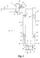
- FIG. 1is a front view of an embodiment of an instrument useful in orthopedic surgery.
- FIG. 5is a cross-sectional view of the structure shown in FIG. 4 , taken along the lines 5 - 5 in FIG. 4 and viewed in the direction of the arrows.
- FIG. 10is a cross-sectional view of the structure shown in FIG. 9 , taken along the lines 10 - 10 in FIG. 9 and viewed in the direction of the arrows.
- a locking arm 148is attached on an opposite side of medial portion 142 .
- An upper end 149 of locking arm 148is attached to medial portion 142 , as by a pin or by welding, gluing or other fixing methods, so that locking arm is effectively biased into a close juxtaposition with medial portion 142 .
- a lower end 150 of locking arm 148includes side tabs 151 and a protrusion 152 .
- Protrusion 152extends through a hole and into the hollow interior of medial portion 142 .
Landscapes
- Health & Medical Sciences (AREA)
- Orthopedic Medicine & Surgery (AREA)
- Surgery (AREA)
- Life Sciences & Earth Sciences (AREA)
- Neurology (AREA)
- Molecular Biology (AREA)
- Heart & Thoracic Surgery (AREA)
- Medical Informatics (AREA)
- Biomedical Technology (AREA)
- Animal Behavior & Ethology (AREA)
- General Health & Medical Sciences (AREA)
- Public Health (AREA)
- Veterinary Medicine (AREA)
- Engineering & Computer Science (AREA)
- Nuclear Medicine, Radiotherapy & Molecular Imaging (AREA)
- Prostheses (AREA)
- Surgical Instruments (AREA)
Abstract
Description
The present disclosure relates to instrumentation useful in orthopedic surgery, and in particular to instrumentation useful in manipulating (e.g. distracting or moving apart) tissues such as bones (e.g. vertebrae) or bone fragments.
Several types of tools for compressing or distracting tissues such as bones or bone fragments toward healing of a trauma or correcting of an abnormality are known. Among these include instruments that use cables to pull together bones or artificial implants placed in such bones, scissor-like tools that apply leverage around a central fulcrum to move bones or implants toward or away from each other, and even the surgeon's own hands. Such manipulations or adjustments of bones are indicated for correction of a number of orthopedic conditions. For example, in the case of a scoliosis or other abnormal positioning of the spine, one or more vertebrae or vertebral segments may require compression or distraction with respect to adjacent bones to achieve a better or more normal position. In the case of a trauma, for example after an injury to a bone or adjacent tissue or removal of a cancerous or other mass, compression or distraction of tissue may be required to induce proper healing, to accommodate a therapy such as implantation of spacing or holding devices or of therapeutic material (e.g. bone morphogenic protein (BMP), allograft, autograft or other osteogenic substances, or medications), or for other reasons. Prior compression and/or distraction tools are not always useful, or may be awkward to use, in certain surgical pathologies or situations. Thus, there remains a need in the art for such instruments that provide advantages over existing tools.
For the purposes of promoting an understanding of the principles of the invention, reference will now be made to the embodiments illustrated in the drawings and specific language will be used to describe the same. It will nevertheless be understood that no limitation of the scope of the invention is thereby intended, such alterations and further modifications in the illustrated device, and such further applications of the principles of the invention as illustrated therein being contemplated, as would normally occur to one skilled in the art to which the invention relates.
An embodiment of aninstrument 30 is shown inFIG. 1 .Instrument 30 hasarms rack 36.Arm 32, in an illustrated embodiment, is substantially rectangular in cross-section along amedial portion 40, and has afirst end 41 that connects torod 36, and asecond end 42. In some embodiments,end 41 is pivotably connected tomedial portion 40 by anaxle 45, which may be a screw or other threaded element. In other embodiments,end 41 may be fixed to or integral withmedial portion 40 so thatend 41 andmedial portion 40 cannot pivot with respect to each other.End 41 is fixed with respect torod 36 in a particular embodiment, as by gluing, welding, interference fitting or otherwise.Second end 42 includes atongue 46 with ahole 47 for accommodating an axle.Tongue 46 may connect to an assembly such asassembly 60 via an axle so thatassembly 60 is pivotable with respect toarm 32.
In a specific embodiment apinion mechanism 72 extends through a part ofend 49 and intochannel 52.Pinion mechanism 72, in one embodiment, has ahandle 74 pivotably connected to apinion 76, which has teeth or ridges inchannel 52 and in contact withteeth 70 orrod 36 in rack-and-pinion fashion, so thatturning pinion mechanism 72 results in linear movement ofarm 34 with respect torod 36. Alocking pawl 78 may be included. In one embodiment,pawl 78 is a lever biased byspring 79 and attached toend 49, having a pushingsurface 80 and a tooth-engaging end 82. Pushing on pushingsurface 80 rotatespawl 78 to disengage tooth-engagingend 82 fromteeth 70 ofrod 36, permitting free movement ofarm 34 with respect torod 36. Releasing pushingsurface 80 allows tooth-engaging end 82 to resume its spring-biasedposition engaging teeth 70. Inembodiments having rod 36,arms pinion mechanism 72 andpawl 78 if included, are pre-assembled prior to surgery to form essentially a single “rack” unit for the surgeon's use.
In the illustrated embodiment,pawl 78 is oriented to allow distraction whilepawl 78 is in its spring-biased state (i.e. when tooth-engagingend 82 engages teeth70), while limiting or preventing compression. To enable compression of bone tissue such as vertebrae, i.e. moving bones or bone pieces generally toward each other,pawl 78 may be disengaged fromteeth 70 in the illustrated embodiment, or may be oriented 180 degrees opposite to what is shown in the illustrated embodiment, or may be left out altogether.
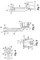
In an illustrated embodiment,assemblies 60 include atip 86, aleg 88, aset screw 90, and one ormore stakes 92.Tip 86, in an illustrated embodiment, is slightly offset with respect toleg 88, makingassembly 60 substantially J-shaped.Tip 86 may be substantially rectangular with rounded corners in cross-section, or may be substantially cylindrical or have any of a variety of cross-sectional shapes. Anopening 94 extends through atop surface 96 oftip 86, and in aparticular embodiment opening 94 is substantially parallel to thearm assembly 60 is connected.Opening 94 is divided intoopenings protrusion 97 alongbottom surface 98 oftip 86.Tab 97 is part cylindrical in one embodiment, and may be of a size approximately the same as a channel through an orthopedic implant. Anaperture 100 throughbottom surface 98 communicates with opening94. Aperture100 and opening94 could be thought of as one opening. In a particular embodiment,aperture 100 is of a size to allow passage of a guide wire throughaperture 100 and opening94. One ormore side openings 102 may also be provided intip 86, and may communicate with opening94. Opening(s)102 are substantially flat or rectangular in the illustrated embodiment to accommodatestakes 92.Openings 102 may be of any appropriate shape that will accommodatestakes 92.
The illustrated embodiment ofset screw 90 has ahead portion 106, acollar 107, and an at least partially threadedshaft 108.Head portion 106 may have anexternal print 109, such as a hexagonal print, or an internal print for accommodating a driving tool.Collar 107 is of a diameter at least slightly less than the diameter ofopening 94. The threads onshaft 108 are configured to be compatible with internal threads on an implant. Aportion 110 ofshaft 108 is not threaded in an illustrated embodiment. In a particular embodiment, setscrew 90 may be cannulated, with anopening 112 having aportion 112A that is sized to accommodate a guide wire, and aportion 112B that is larger in diameter thanportion 112A and has a conicalsurface adjoining portion 112A to aid one in placing a guide wire through setscrew 90.
Use of an embodiment ofinstrument 30 will now be described with reference to a surgical procedure on the spine using bone screws such as those shown in U.S. Pat. No. 5,005,562 or U.S. Pat. No. 5,797,911, which have a head with two branches forming a U-shaped channel that is internally threaded, as an example. As noted above,instrument 30 may be used in a variety of orthopedic treatments, at other surgical sites, and/or with other types of implants.
To treat the condition or injury of the patient, the surgeon obtains access to the surgical site in a manner well known in the art, e.g. through incision and refraction of tissues. Once access to the surgical site has been obtained, e.g. via an opening such as a midline incision above the affected area, with tissue being resected laterally to the transverse process, or by other surgical procedure. The surgeon may connect one or more screws to adjacent or nearby vertebrae that require compression or distraction in order to relieve or improve their condition. For example, pilot holes in vertebrae, e.g. in pedicles, may be made, and screws may be inserted into or otherwise connected to two or more vertebrae. In one embodiment, a support member (for example, a spinal rod, with or without appropriate lateral or other connectors) may be connected to the screws, as by placing or reducing it into the channels in the screws, and tightening to one of the screws.
Once such implants are placed as desired by the surgeon, the surgeon can moveinstrument 30 into position adjacent the implants. The surgeon may first adjust the distance betweenarms aperture 100 is provided, and in which cannulated implants have been placed with the assistance of a guide wire, the guide wire can be inserted throughaperture 100 and opening94 oftip 86, andtip 86 can be moved along the guide wire until it is adjacent or abutting the implant. Referring again for convenience to an implanted screw S, the screw head and/ortip 86 is maneuvered so that branches B of screw S at least partially enteropenings bottom surface 98 oftip 86. In one embodiment, branches B are advanced intotip 86 so thattab 97 is within the channel between branches B, and in a particular embodiment branches B are advanced so thattab 97 is adjacent to or abutting a floor of the channel between branches B.
Setscrew 90 is then turned so as to thread itsshaft 110 into the threaded channel of the bone screwS. Set screw 90 may be turned as desired by the surgeon. If it is turned relatively little, it may simply engage the threads in the bone screw channel to hold the bone screw intip 86. If setscrew 90 is tightened substantially, then it will draw bone screw S further intotip 86 untiltab 97 abuts the floor of the channel of the bone screw or a support member within the channel. In the latter case, the bone screw head is securely fixed with respect to tip86. The head of the bone screw is held from turning withset screw 90 by thetab 97 within the bone screw channel. With tightening ofset screw 90 so thattab 97 is forced against the bone screw or other implant head, the screw S may be locked so that the branches and implant head are substantially inhibited from motion relative to each other or to tip86. Such locking may be analogous to the locking that occurs when a set screw is tightened against a rod within a screw S, such as is also disclosed in U.S. Pat. No. 5,797,911.
When each ofassemblies 60 is connected or locked to a respective bone screw head, compression or distraction of the bones to which the bone screws are attached can occur.Operating pinion mechanism 72, e.g. by turninghandle 74, to movearms FIG. 1 , turninghandle 74 counterclockwise will forcearm 34 alongrod 36 away fromarm 32 and distract bones connected toarms assemblies 60. Turninghandle 74 clockwise (assuming modifications to or release ofpawl 78, as disclosed above, have taken place) will forcearm 34 towardarm 32 to compress bones connected toarms screws 90 for eachassembly 60 may be unscrewed from the channels of their respective bone screws, allowingassemblies 60 and the rest of the instrument to be pulled away from the bone implants and away from the surgical site. In embodiments in whichset screw 90 can be removed from tip86 (i.e. stakes92 do not interfere withshaft 110 of set screw90), a locking screw can be placed throughopening 94 and into the head of bone screw S to lock it. If a guide wire is used, setscrew 90 may be removed along the guide wire, and a cannulated locking screw can be inserted along the guide wire. The surgeon can complete the locking of the implants and support(s), and otherwise complete the surgical procedure.
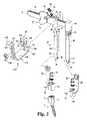
Referring generally toFIG. 11 , there is shown another embodiment ofarms instrument 30.Arms arms arm 132 is made integral withrod 36 and in the ways discussed below, and are otherwise substantially the same asarms instrument 30 shown inFIG. 1 are substantially similar or identical to the embodiment shown inFIG. 11 .
For simplicity, features ofarm 132 will be described, it being understood that similar or identical features are found inarm 134. The illustrated embodiment ofarm 132 includes amedial portion 142 that is hollow through a lower portion and substantially square or rectangular. On one side ofmedial portion 142, in one particular embodiment the side not facing theother arm 134, twoflanged protrusions 144 are provided that connect with aretractor blade 146 viaoblong holes 148 that are larger at a middle portion (e.g. slightly larger than the flange of protrusions144) than at end portions.Retractor blade 146 assists in holding or moving tissue out of the way whenarm 132 is at the surgical site and/or in the midst of distraction or compression procedure. On an opposite side of medial portion142 alocking arm 148 is attached. Anupper end 149 of lockingarm 148 is attached tomedial portion 142, as by a pin or by welding, gluing or other fixing methods, so that locking arm is effectively biased into a close juxtaposition withmedial portion 142. Alower end 150 of lockingarm 148 includesside tabs 151 and aprotrusion 152.Protrusion 152 extends through a hole and into the hollow interior ofmedial portion 142.
In this embodiment, aleg 156 connected to tip86 is configured to fit withinmedial portion 142 in a telescoping manner.Leg 156 includes a series ofholes 158 along its length.Holes 158 may be spaced uniformly along the length ofleg 156.Holes 158 are on a side ofleg 156 that will faceprotrusion 152 of lockingarm 148 whenleg 156 is inserted intomedial portion 142, and are sized so thatprotrusion 152 can fit inside them.Leg 156 is thus adjustable with respect tomedial portion 142, so that the overall length fromrod 36 to tip86 is variable. Pulling one or bothside tabs 151 or another part of lockingarm 148 removesprotrusion 152 from withinmedial portion 142.Leg 156 can then be moved withinmedial portion 142 to a desired relative position, and lockingarm 148 is released. Lockingarm 148 returns to its unstressed condition, andprotrusion 152 entersmedial portion 142 and one ofholes 158, holdingleg 156 in a desired position relative tomedial portion 142.
As seen in the embodiment shown inFIG. 2 , aretractor blade assembly 170 may be provided with an embodiment ofinstrument 30.Assembly 170 includes aretractor blade 172 that is substantially L-shaped in the illustrated embodiment, having afirst leg 174 with alongitudinal slot 176 and an extendingtab 178, and asecond leg 180 substantially perpendicular toleg 174 and having anend portion 182 with aU-shaped opening 184 and a set ofteeth 186.End portion 182 in a particular embodiment is at an angle with respect toleg 180. A holdingpiece 188 having achannel 190 and an extendingshaft 192 is also provided.Channel 190 may be sized and configured so that a portion ofrod 36 can fit within it and holdingpiece 188 can sit onrod 36.Shaft 192 is threaded and pivotable along aslot 194 in the illustrated embodiment, and is inserted throughslot 176 inleg 174. Anut 196, such as a wing nut, can be tightened ontoshaft 192 to secure holdingpiece 188 toleg 174, and to limit or prevent further pivoting ofshaft 192.
It has been previously noted thatrod 36, with ends41 and49 ofarms 32 and34 (orarms 132 and134), may be pivoted aroundaxles instrument 30 to the surgical environment and physical needs of the case.
It will be appreciated that the parts of the embodiments shown and described may be made of biocompatible materials such as stainless steel, titanium, ceramics or hard plastics, or other known or developed biocompatible materials. Materials that can be easily sterilized and reused may be particularly useful.
In the embodiments shown and described above,tips 86 are substantially between thelegs 88 ofassemblies 60, or betweenarms tips 86 to the side of or outside oflegs 88 orarms rod 36.
While the illustrated embodiments show two arms each with a tip as disclosed, it will be seen that an instrument can be made and used in which one such arm (e.g. arm32) is provided with a tip such astip 86, and a different structure or mechanism is provided for connecting to a bone, implant or other object.
The U.S. patent application Ser. No. 11/118,641, entitled INSTRUMENT FOR COMPRESSION OR DISTRACTION, filed on Apr. 29, 2005, first-named inventor Alan Rezach, is incorporated herein by reference in its entirety.
While the invention has been illustrated and described in detail in the drawings and foregoing description, the same is to be considered as illustrative and not restrictive in character, it being understood that only the preferred embodiment has been shown and described and that all changes and modifications that come within the spirit of the invention are desired to be protected.
Claims (45)
1. An apparatus for connecting to orthopedic implants having upper branches defining a channel, comprising:
a first arm and a second arm, said arms being movable with respect to each other substantially in a plane;
a pair of tips, one of said tips connected to said first arm and the other of said tips connected to said second arm, each said tip including an opening therethrough, a tab along a bottom surface of said tip that bifurcates said opening in a lower portion of said tip, said opening in a lower portion of said tip configured to accommodate the branches of an orthopedic implant so that said tab is between the branches; and
an anchor member within said opening in an upper portion of each said tip having a head portion and a lower portion, said lower portion adapted to connect to at least one of the branches of an orthopedic implant when the branches are in said tip, so that the implant is held in said tip,
whereby moving said arms with respect to each other moves said tips and the implants held therein with respect to each other.
2. The apparatus ofclaim 1 , wherein said arms are connected by an elongated member.
3. The apparatus ofclaim 2 , wherein said elongated member includes teeth, and one of said arms is connected to a pinion engaged to said teeth, whereby turning said pinion moves said arm with respect to said elongated member.
4. The apparatus ofclaim 3 , wherein said arm not connected to said pinion is fixed with respect to said elongated member.
5. The apparatus ofclaim 2 , wherein said elongated member is connected to said arms by axles, whereby said elongated member is pivotable with respect to said arms.
6. The apparatus ofclaim 1 , further comprising a retractor blade connected to said elongated member, said retractor blade having a leg, said retractor blade being pivotable with respect to said elongated member and adjustable so that said leg can be at any of a number of distances from said elongated member.
7. The apparatus ofclaim 1 , further comprising at least one retractor blade connected to at least one of said arms.
8. The apparatus ofclaim 1 , wherein said arms each include a medial portion, and each said tip is connected to its respective medial portion via a respective axle, whereby said tip is able to pivot with respect to said medial portion.
9. The apparatus ofclaim 1 , wherein a hole extends through said tab and communicates with said opening, said hole being large enough to pass a guide wire therethrough.
10. The apparatus ofclaim 1 , wherein said anchor member is a screw having a threaded portion, a head portion, a collar, and a hole therethrough, said hole being at least large enough to pass a guide wire therethrough.
11. The apparatus ofclaim 1 , wherein a tab of at least one of said tips extends from the bottom surface of said tip.
12. An apparatus for connecting to orthopedic implants having upper branches defining a channel, comprising:
a first arm and a second arm, said arms being movable with respect to each other substantially in a plane;
a pair of tips, one of said tips connected to said first arm and the other of said tips connected to said second arm, each said tip including an opening therethrough, a tab along a bottom surface of said tip that bifurcates said opening in a lower portion of said tip, said opening in a lower portion of said tip configured to accommodate the branches of an orthopedic implant so that said tab is between the branches;
an anchor member within said opening in an upper portion of each said tip having a head portion and a lower portion, said lower portion adapted to connect to at least one of the branches of an orthopedic implant when the branches are in said tip, so that the implant is held in said tip,
whereby moving said arms with respect to each other moves said tips and the implants held therein with respect to each other;
wherein said arms each include a hollow medial portion, and each said tip is connected to a respective leg, each said leg fitting telescopically within a respective medial portion; and
wherein each said leg includes a plurality of holes, and each said medial portion is provided with a locking arm having a protrusion, said protrusion extending into said medial portion, said protrusion sized to be able to fit at least partially into said holes, whereby said leg is adjustable with respect to said medial portion and said tip is positionable at a plurality of distances from said medial portion.
13. The apparatus ofclaim 12 , wherein said arms each include a hollow medial portion, and each said tip is connected to a respective leg, each said leg fitting telescopically within a respective medial portion.
14. The apparatus ofclaim 12 , wherein each said tip includes at least one side aperture that communicates with said opening, and further comprising at least one stake inserted into at least one said side aperture so that a portion of said stake extends into said opening.
15. The apparatus ofclaim 14 , wherein said anchor member includes a collar sized so that said collar cannot pass said at least one stake.
16. The apparatus ofclaim 12 , wherein said anchor member is a set screw.
17. The apparatus ofclaim 12 , wherein at least one of said tips includes a pair of side apertures, and further comprising a pair of stakes each fixed in a respective one of said side apertures so that a portion of said stakes extend into said opening.
18. The apparatus ofclaim 17 , wherein at least one of said stakes includes a concave surface, said concave surface being at least partially within said opening.
19. The apparatus ofclaim 12 , wherein at least one of said arms includes a hollow medial portion;
the apparatus further comprising a leg connected to at least one of said tips, said leg having a plurality of holes and configured to be inserted telescopically into said hollow medial portion; and
a locking arm connected to said hollow medial portion, said locking arm having a protrusion that extends into said hollow medial portion and into one of said holes in said leg so that the length of said leg extending from said hollow medial portion is variable.
20. An apparatus for connecting to orthopedic implants having upper branches defining a channel, comprising:
a first arm and a second arm, said arms being movable with respect to each other substantially in a plane;
a pair of tips, one of said tips connected to said first arm and the other of said tips connected to said second arm, each said tip including an opening therethrough, a tab along a bottom surface of said tip that bifurcates said opening in a lower portion of said tip, said opening in a lower portion of said tip configured to accommodate the branches of an orthopedic implant so that said tab is between the branches;
an anchor member within said opening in an upper portion of each said tip having a head portion and a lower portion, said lower portion adapted to connect to at least one of the branches of an orthopedic implant when the branches are in said tip, so that the implant is held in said tip,
whereby moving said arms with respect to each other moves said tips and the implants held therein with respect to each other; and
wherein each said tip includes at least one side aperture that communicates with said opening, and further comprising at least one stake inserted into at least one said side aperture so that a portion of said stake extends into said opening.
21. The apparatus ofclaim 20 , wherein said anchor member includes a collar sized so that said collar cannot pass said at least one stake.
22. The apparatus ofclaim 20 , wherein said arms each include a hollow medial portion, and each said tip is connected to a respective leg, each said leg fitting telescopically within a respective medial portion.
23. The apparatus ofclaim 20 , wherein said anchor member is a set screw.
24. The apparatus ofclaim 20 , wherein at least one of said tips includes a pair of side apertures, and further comprising a pair of stakes each fixed in a respective one of said side apertures so that a portion of said stakes extend into said opening.
25. The apparatus ofclaim 24 , wherein at least one of said stakes includes a concave surface, said concave surface being at least partially within said opening.
26. The apparatus ofclaim 20 , wherein at least one of said arms includes a hollow medial portion;
the apparatus further comprising a leg connected to at least one of said tips, said leg having a plurality of holes and configured to be inserted telescopically into said hollow medial portion; and
a locking arm connected to said hollow medial portion, said locking arm having a protrusion that extends into said hollow medial portion and into one of said holes in said leg so that the length of said leg extending from said hollow medial portion is variable.
27. An apparatus for connecting to orthopedic implants having upper branches defining a channel, comprising:
an arm;
an elongated member connected to said arm, said arm being movable along the length of said elongated member;
a tip connected to said arm, said tip including an opening therethrough, a tab along a bottom surface of said tip that bifurcates said opening in a lower portion of said tip, said opening in a lower portion of said tip configured to accommodate the branches of an orthopedic implant so that said tab is between the branches; and
an anchor member within said opening in said tip, said anchor member having a head portion and a lower portion, said lower portion adapted to connect to at least one of the branches of an orthopedic implant when the branches are in said tip, so that the implant is held in said tip,
whereby moving said arm with respect to said elongated member moves said tip and the implant held therein with respect to said elongated member.
28. The apparatus ofclaim 27 , wherein said arm includes a tongue having a hole therethrough;
the apparatus further comprising a leg having a first end and a second end, said first end connected to said tip, said second end having a pair of prongs defining a slot, each said prong having hole therethrough;
said tongue being inserted into said slot so that said hole in said tongue and said holes in said prongs are substantially collinear; and
further comprising an axle inserted through said hole in said tongue and said holes in said prongs,
whereby said leg and said tip can be pivoted with respect to said arm.
29. The apparatus ofclaim 28 , wherein at least one of said prong holes includes internal threads, and said axle is at least partially threaded, so that said axle can be threaded into said at least one threaded prong hole.
30. The apparatus ofclaim 27 , wherein said tab has a hole therethrough, said hole being at least large enough to allow a guide wire to pass through.
31. The apparatus ofclaim 27 wherein said anchor member has a collar for retaining said anchor member within said opening.
32. The apparatus ofclaim 27 wherein said anchor member has a hole sized at least large enough to pass a guide wire therethrough.
33. The apparatus ofclaim 27 wherein said elongated member is connected to said arm via an axle.
34. The apparatus ofclaim 33 , wherein said axle is substantially perpendicular to said arm.
35. The apparatus ofclaim 33 , wherein said axle is substantially parallel to said elongated member.
36. The apparatus ofclaim 27 , wherein said tab of said tip extends from the bottom surface of said tip.
37. An apparatus for connecting to orthopedic implants having upper branches defining a channel, comprising:
an arm;
an elongated member connected to said arm, said arm being movable along the length of said elongated member;
a tip connected to said arm, said tip including an opening therethrough, a tab along a bottom surface of said tip that bifurcates said opening in a lower portion of said tip, said opening in a lower portion of said tip configured to accommodate the branches of an orthopedic implant so that said tab is between the branches;
an anchor member within said opening in said tip, said anchor member having a head portion and a lower portion, said lower portion adapted to connect to at least one of the branches of an orthopedic implant when the branches are in said tip, so that the implant is held in said tip,
whereby moving said arm with respect to said elongated member moves said tip and the implant held therein with respect to said elongated member; and
wherein said tip includes a pair of side apertures, and further comprising a pair of stakes each fixed in a respective one of said side apertures so that a portion of said stakes extend into said opening.
38. The apparatus ofclaim 37 , wherein at least one of said stakes includes a concave surface, said concave surface being at least partially within said opening.
39. The apparatus ofclaim 37 , wherein said arm includes a hollow medial portion, and said tip is connected to a leg, said leg fitting telescopically within said hollow medial portion.
40. The apparatus ofclaim 37 , wherein said arm includes a hollow medial portion;
the apparatus further comprising a leg connected to said tip, said leg having a plurality of holes and configured to be inserted telescopically into said hollow medial portion; and
a locking arm connected to said medial portion, said locking arm having a protrusion that extends into said medial portion and into one of said holes in said leg so that the length of said leg extending from said medial portion is variable.
41. An apparatus for connecting to orthopedic implants having upper branches defining a channel, comprising:
an arm;
an elongated member connected to said arm, said arm being movable along the length of said elongated member;
a tip connected to said arm, said tip including an opening therethrough, a tab along a bottom surface of said tip that bifurcates said opening in a lower portion of said tip, said opening in a lower portion of said tip configured to accommodate the branches of an orthopedic implant so that said tab is between the branches;
an anchor member within said opening in said tip, said anchor member having a head portion and a lower portion, said lower portion adapted to connect to at least one of the branches of an orthopedic implant when the branches are in said tip, so that the implant is held in said tip,
whereby moving said arm with respect to said elongated member moves said tip and the implant held therein with respect to said elongated member;
wherein said arm includes a hollow medial portion;
the apparatus further comprising a leg connected to said tip, said leg having a plurality of holes and configured to be inserted telescopically into said hollow medial portion; and
a locking arm connected to said medial portion, said locking arm having a protrusion that extends into said medial portion and into one of said holes in said leg so that the length of said leg extending from said medial portion is variable.
42. An apparatus for connecting to orthopedic implants having upper branches defining a channel, comprising:
a first arm and a second arm, said arms being movable with respect to each other substantially in a plane;
a pair of tips, one of said tips connected to said first arm and the other of said tips connected to said second arm, each said tip including an opening therethrough, a tab along a bottom surface of said tip that bifurcates said opening in a lower portion of said tip, said opening in a lower portion of said tip configured to accommodate the branches of an orthopedic implant so that said tab is between the branches; and
an anchor member within said opening in an upper portion of each said tip having a head portion and a lower portion, said lower portion adapted to connect to at least one of the branches of an orthopedic implant when the branches are in said tip, so that the implant is held in said tip,
whereby moving said arms with respect to each other moves said tips and the implants held therein with respect to each other, and wherein at least one of said tips is offset from one of said arms in a direction substantially toward another of said tips.
43. An apparatus for connecting to orthopedic implants having upper branches defining a channel, comprising:
a first arm and a second arm, said arms being movable with respect to each other substantially in a plane;
a pair of tips, one of said tips connected to said first arm and the other of said tips connected to said second arm, each said tip including an opening therethrough, a tab along a bottom surface of said tip that bifurcates said opening in a lower portion of said tip, said opening in a lower portion of said tip configured to accommodate the branches of an orthopedic implant so that said tab is between the branches; and
an anchor member within said opening in an upper portion of each said tip having a head portion and a lower portion, said lower portion adapted to connect to at least one of the branches of an orthopedic implant when the branches are in said tip, so that the implant is held in said tip,
whereby moving said arms with respect to each other moves said tips and the implants held therein with respect to each other, and wherein said tips are offset from their respective arms in a direction substantially toward each other.
44. An apparatus for connecting to orthopedic implants having upper branches defining a channel, comprising:
an arm;
an elongated member connected to said arm, said arm being movable along the length of said elongated member;
a tip connected to said arm, said tip including an opening therethrough, a tab along a bottom surface of said tip that bifurcates said opening in a lower portion of said tip, said opening in a lower portion of said tip configured to accommodate the branches of an orthopedic implant so that said tab is between the branches; and
an anchor member within said opening in said tip, said anchor member having a head portion and a lower portion, said lower portion adapted to connect to at least one of the branches of an orthopedic implant when the branches are in said tip, so that the implant is held in said tip,
whereby moving said arm with respect to said elongated member moves said tip and the implant held therein with respect to said elongated member, and wherein said tip is offset from said arm in a direction substantially parallel to said elongated member.
45. An apparatus for connecting to orthopedic implants having upper branches defining a channel, comprising:
a first arm and a second arm, said arms being movable with respect to each other substantially in a plane;
a pair of tips, one of said tips connected to said first arm and the other of said tips connected to said second arm, each said tip including an opening therethrough, a tab along a bottom surface of said tip that bifurcates said opening in a lower portion of said tip, said opening in a lower portion of said tip configured to accommodate the branches of an orthopedic implant so that said tab is between the branches; and
an anchor member within said opening in an upper portion of each said tip having a head portion and a lower portion, said lower portion adapted to connect to at least one of the branches of an orthopedic implant when the branches are in said tip, so that the implant is held in said tip,
whereby moving said arms with respect to each other moves said tips and the implants held therein with respect to each other, and wherein said arms each include a hollow medial portion, and each said tip is connected to a respective leg, each said leg fitting telescopically within a respective medial portion.
Priority Applications (2)
| Application Number | Priority Date | Filing Date | Title |
|---|---|---|---|
| US11/118,513US7618424B2 (en) | 2005-04-29 | 2005-04-29 | Orthopedic instrument |
| PCT/US2006/016184WO2006118999A2 (en) | 2005-04-29 | 2006-04-27 | Orthopedic instrument |
Applications Claiming Priority (1)
| Application Number | Priority Date | Filing Date | Title |
|---|---|---|---|
| US11/118,513US7618424B2 (en) | 2005-04-29 | 2005-04-29 | Orthopedic instrument |
Publications (2)
| Publication Number | Publication Date |
|---|---|
| US20060247645A1 US20060247645A1 (en) | 2006-11-02 |
| US7618424B2true US7618424B2 (en) | 2009-11-17 |
Family
ID=37235439
Family Applications (1)
| Application Number | Title | Priority Date | Filing Date |
|---|---|---|---|
| US11/118,513Active2026-09-14US7618424B2 (en) | 2005-04-29 | 2005-04-29 | Orthopedic instrument |
Country Status (2)
| Country | Link |
|---|---|
| US (1) | US7618424B2 (en) |
| WO (1) | WO2006118999A2 (en) |
Cited By (40)
| Publication number | Priority date | Publication date | Assignee | Title |
|---|---|---|---|---|
| US20110130634A1 (en)* | 2009-05-20 | 2011-06-02 | Synthes Usa, Llc | Patient-mounted retraction |
| US20120035611A1 (en)* | 2010-08-06 | 2012-02-09 | Warsaw Orthopedic, Inc. | Measuring instrument for sizing an elongate stabilization element |
| US20120265212A1 (en)* | 2011-04-18 | 2012-10-18 | Warsaw Orthopedic, Inc | Apparatus and method for sizing a connecting element for positioning along a bone structure |
| US8535318B2 (en) | 2010-04-23 | 2013-09-17 | DePuy Synthes Products, LLC | Minimally invasive instrument set, devices and related methods |
| US9066762B2 (en) | 2004-12-02 | 2015-06-30 | Zimmer Spine, Inc. | Instruments and methods for adjusting separation distance of vertebral bodies with a minimally invasive spinal stabilization procedure |
| US9179947B2 (en) | 2012-07-03 | 2015-11-10 | Tedan Surgical Innovations, Llc | Locking distractor with two-start distraction screw |
| US20160074073A1 (en)* | 2013-03-11 | 2016-03-17 | Stryker European Holdings I, Llc | Distraction/compression posterior rod system and methods of use |
| US9314274B2 (en) | 2011-05-27 | 2016-04-19 | DePuy Synthes Products, Inc. | Minimally invasive spinal fixation system including vertebral alignment features |
| US9402660B2 (en) | 2013-09-05 | 2016-08-02 | Warsaw Orthopedic, Inc. | Surgical instrument and method |
| US9498262B2 (en) | 2006-04-11 | 2016-11-22 | DePuy Synthes Products, Inc. | Minimally invasive fixation system |
| US9795370B2 (en) | 2014-08-13 | 2017-10-24 | Nuvasive, Inc. | Minimally disruptive retractor and associated methods for spinal surgery |
| US20170311987A1 (en)* | 2016-04-27 | 2017-11-02 | Warsaw Orthopedic, Inc | Spinal correction system and method |
| US9907582B1 (en) | 2011-04-25 | 2018-03-06 | Nuvasive, Inc. | Minimally invasive spinal fixation system and related methods |
| US10194958B2 (en) | 2016-04-27 | 2019-02-05 | Warsaw Othopedic, Inc. | Spinal correction system and method |
| US10194960B1 (en) | 2015-12-03 | 2019-02-05 | Nuvasive, Inc. | Spinal compression instrument and related methods |
| USD842479S1 (en) | 2016-04-27 | 2019-03-05 | Warsaw Orthopedic, Inc. | Spinal implant |
| US10363022B2 (en) | 2017-10-18 | 2019-07-30 | Spine Wave, Inc. | Screw based retractor with expandable blades |
| US10499897B2 (en) | 2017-03-06 | 2019-12-10 | Thompson Surgical Instruments, Inc. | Distractor with bidirectional ratchet |
| US10543022B2 (en) | 2016-10-11 | 2020-01-28 | Warsaw Orthopedic, Inc. | Spinal implant system and method |
| US10646261B2 (en) | 2018-07-24 | 2020-05-12 | Warsaw Orthopedic, Inc. | Multi-purpose screwdriver and method of use |
| US20210186576A1 (en)* | 2009-11-10 | 2021-06-24 | Nuvasive, Inc. | Method and Apparatus for Performing Spinal Surgery |
| US11051859B2 (en) | 2016-04-27 | 2021-07-06 | Warsaw Orthopedic, Inc. | Spinal correction system and method |
| US11185319B2 (en)* | 2019-02-11 | 2021-11-30 | Warsaw Orthopedic, Inc. | Surgical distractor and method |
| US11350922B1 (en) | 2021-02-03 | 2022-06-07 | Warsaw Orthopedic, Inc. | Modular surgical instrument system and method for shank-based retraction and distraction |
| US11406431B1 (en) | 2021-05-10 | 2022-08-09 | Warsaw Orthopedic, Inc. | Systems and methods of use and modular instruments with a lateral reducer |
| US11413028B2 (en) | 2017-10-18 | 2022-08-16 | Spine Wave, Inc. | Screw-based retractor having arms with plural discrete selectively lockable positions |
| US11432852B1 (en) | 2021-03-22 | 2022-09-06 | Warsaw Orthopedic, Inc. | Screw shank based tissue retraction |
| US11596443B2 (en) | 2018-07-11 | 2023-03-07 | Treace Medical Concepts, Inc. | Compressor-distractor for angularly realigning bone portions |
| US11607250B2 (en) | 2019-02-13 | 2023-03-21 | Treace Medical Concepts, Inc. | Tarsal-metatarsal joint procedure utilizing compressor-distractor and instrument providing sliding surface |
| US11617603B2 (en) | 2020-12-09 | 2023-04-04 | Warsaw Orthopedic, Inc. | Modular surgical instrument system with ratcheting reduction mechanism |
| USD1011524S1 (en) | 2022-02-23 | 2024-01-16 | Treace Medical Concepts, Inc. | Compressor-distractor for the foot |
| US11889998B1 (en) | 2019-09-12 | 2024-02-06 | Treace Medical Concepts, Inc. | Surgical pin positioning lock |
| USD1042827S1 (en)* | 2022-06-06 | 2024-09-17 | Koros USA, Inc. | Medical retractor |
| USD1051382S1 (en) | 2022-02-23 | 2024-11-12 | Treace Medical Concepts, Inc. | Lesser metatarsal cut guide |
| USD1057155S1 (en) | 2022-02-23 | 2025-01-07 | Treace Medical Concepts, Inc. | Lesser metatarsal cut guide with parallel cut faces |
| US12207811B2 (en) | 2022-05-24 | 2025-01-28 | Globus Medical, Inc. | TLIF distraction and retraction |
| US12295624B2 (en) | 2022-05-24 | 2025-05-13 | Globus Medical, Inc. | TLIF distraction and retraction |
| USD1079011S1 (en) | 2022-02-23 | 2025-06-10 | Treace Medical Concepts, Inc. | Metatarsal cut guide with parallel cut faces |
| US12324610B2 (en) | 2021-04-28 | 2025-06-10 | Spinal Elements, Inc. | Lever reducer |
| US12440248B2 (en) | 2022-06-28 | 2025-10-14 | DePuy Synthes Products, Inc. | Minimally invasive instrument set, devices, and related methods |
Families Citing this family (44)
| Publication number | Priority date | Publication date | Assignee | Title |
|---|---|---|---|---|
| US20080027548A9 (en) | 2002-04-12 | 2008-01-31 | Ferree Bret A | Spacerless artificial disc replacements |
| US8038713B2 (en) | 2002-04-23 | 2011-10-18 | Spinecore, Inc. | Two-component artificial disc replacements |
| US6908484B2 (en) | 2003-03-06 | 2005-06-21 | Spinecore, Inc. | Cervical disc replacement |
| WO2006058221A2 (en)* | 2004-11-24 | 2006-06-01 | Abdou Samy M | Devices and methods for inter-vertebral orthopedic device placement |
| US8777959B2 (en) | 2005-05-27 | 2014-07-15 | Spinecore, Inc. | Intervertebral disc and insertion methods therefor |
| US8696560B2 (en) | 2006-05-02 | 2014-04-15 | K2M, Inc. | Minimally open retraction device |
| US8016832B2 (en)* | 2007-05-02 | 2011-09-13 | Zimmer Spine, Inc. | Installation systems for spinal stabilization system and related methods |
| US20110184426A1 (en)* | 2007-09-04 | 2011-07-28 | Garces Martin Gerardo | Device for fixing screws in osteoporotic bones |
| WO2009055541A1 (en)* | 2007-10-23 | 2009-04-30 | K2M, Inc. | Implant insertion tool |
| AU2009205679B2 (en) | 2008-01-18 | 2013-12-05 | Spinecore, Inc. | Instruments and methods for inserting artificial intervertebral implants |
| US9066763B2 (en)* | 2008-07-31 | 2015-06-30 | Zimmer Spine, Inc. | Surgical instrument with integrated reduction and distraction mechanisms |
| US8287546B2 (en) | 2008-07-31 | 2012-10-16 | Zimmer Spine, Inc. | Surgical instrument with integrated compression and distraction mechanisms |
| US20110224736A1 (en)* | 2010-03-09 | 2011-09-15 | Humphrey C Scott | Proximal humerus fracture repair plate and system |
| CN102370501B (en)* | 2010-08-24 | 2015-02-18 | 上海市杨浦区中心医院 | Spine single-side opener |
| AU2014203469B2 (en)* | 2010-10-08 | 2016-08-11 | K2M, Inc. | Lateral access system and method of use |
| US8449463B2 (en) | 2010-10-08 | 2013-05-28 | K2M, Inc. | Lateral access system and method of use |
| US9125703B2 (en)* | 2012-01-16 | 2015-09-08 | K2M, Inc. | Rod reducer, compressor, distractor system |
| WO2013158660A1 (en)* | 2012-04-17 | 2013-10-24 | Alphatec Spine, Inc. | Instrument and method for spinal compression and distraction |
| US10835228B2 (en)* | 2012-07-17 | 2020-11-17 | Warsaw Orthopedic, Inc. | Surgical retractor and method of use |
| WO2014018624A1 (en)* | 2012-07-27 | 2014-01-30 | Spinal Usa, Inc. | Minimally invasive devices, systems and methods for treating the spine |
| EP2705799B1 (en)* | 2012-09-06 | 2015-05-13 | Medacta International S.A. | Surgical device for minimally invasive spinal fusion and surgical system comprising the same |
| ES2465766B1 (en)* | 2012-11-06 | 2015-06-02 | Fundación Pública Andaluza Progreso Y Salud | SURGICAL CLAMP FOR APPROXIMATION AND REDUCTION OF BONE FRAGMENTS |
| US9078710B2 (en)* | 2012-12-12 | 2015-07-14 | Wright Medical Technology, Inc. | Orthopedic compression/distraction device |
| US9770272B2 (en) | 2012-12-12 | 2017-09-26 | Wright Medical Technology, Inc. | Orthopedic compression/distraction device |
| JP6104453B2 (en)* | 2013-03-14 | 2017-03-29 | ライト メディカル テクノロジー インコーポレイテッドWright Medical Technology, Inc. | Orthopedic compression / distraction device |
| CA2874390C (en)* | 2013-12-13 | 2018-03-06 | Stryker European Holdings I, Llc | Tissue retraction and vertebral displacement devices, systems, and methods for posterior spinal fusion |
| US10278786B2 (en)* | 2014-02-18 | 2019-05-07 | Globus Medical, Inc. | Retracting tissue |
| JP2016528993A (en)* | 2014-03-14 | 2016-09-23 | ライト メディカル テクノロジー インコーポレイテッドWright Medical Technology, Inc. | Orthopedic compression / distraction device |
| US10499894B2 (en) | 2015-08-12 | 2019-12-10 | K2M, Inc. | Orthopedic surgical system including surgical access systems, distraction systems, and methods of using same |
| US10149674B2 (en) | 2015-08-12 | 2018-12-11 | K2M, Inc. | Orthopedic surgical system including surgical access systems, distraction systems, and methods of using same |
| US10278687B2 (en)* | 2015-08-18 | 2019-05-07 | Globus Medical, Inc. | Devices and systems for surgical retraction |
| US9924932B2 (en)* | 2015-12-01 | 2018-03-27 | Seth K. WILLIAMS | Technique and system for lateral lumbar spine fusion |
| CN106361390B (en)* | 2015-12-29 | 2019-02-22 | 闻泰医疗科技(上海)有限公司 | A kind of two-way device for spreading of cervical vertebra |
| WO2017200555A1 (en)* | 2016-05-20 | 2017-11-23 | Choicespine, Lp | Access instruments to extend a surgical working channel |
| AU2017235887B2 (en) | 2016-09-26 | 2021-09-30 | K2M, Inc. | Retraction system and method of use |
| WO2018087736A1 (en)* | 2016-11-14 | 2018-05-17 | Premia Spine Ltd. | Surgical retractor with connection to pedicle screws |
| US10779866B2 (en) | 2016-12-29 | 2020-09-22 | K2M, Inc. | Rod reducer assembly |
| EP3517062B1 (en)* | 2018-01-26 | 2021-03-17 | Aesculap AG | Spinal repositioning instrument and spinal repositioning system |
| CN108420473B (en)* | 2018-02-12 | 2019-12-13 | 中南大学湘雅医院 | Distracter for implanting intervertebral implant |
| WO2022027085A1 (en)* | 2020-08-05 | 2022-02-10 | Bradley Ryan | An orthopaedic compression and distraction device and method |
| CN113081104A (en)* | 2021-04-30 | 2021-07-09 | 徐州医科大学附属医院 | Intervertebral spreader with adjustable lumbar vertebra pedicle of vertebral arch screw and scale |
| WO2023091616A1 (en)* | 2021-11-18 | 2023-05-25 | Astura Medical Inc. | En bloc connector |
| CN114027900A (en)* | 2021-12-16 | 2022-02-11 | 王侃 | Retractor for external chest clinic and use method thereof |
| US11744571B1 (en)* | 2022-06-27 | 2023-09-05 | Warsaw Orthopedic, Inc. | Surgical system and method for treating vertebral segments with uneven pedicles |
Citations (17)
| Publication number | Priority date | Publication date | Assignee | Title |
|---|---|---|---|---|
| US2779966A (en)* | 1953-04-20 | 1957-02-05 | Robert E Torchia | Adjustable hinge |
| US4585247A (en)* | 1983-07-26 | 1986-04-29 | Honda Giken Kogyo Kabushiki Kaisha | Body frame of a small-sized vehicle |
| US4957495A (en)* | 1987-04-01 | 1990-09-18 | Patrick Kluger | Device for setting the spinal column |
| US5005562A (en) | 1988-06-24 | 1991-04-09 | Societe De Fabrication De Material Orthopedique | Implant for spinal osteosynthesis device, in particular in traumatology |
| US5795291A (en)* | 1994-11-10 | 1998-08-18 | Koros; Tibor | Cervical retractor system |
| US5797911A (en) | 1996-09-24 | 1998-08-25 | Sdgi Holdings, Inc. | Multi-axial bone screw assembly |
| FR2821543A1 (en) | 2001-03-01 | 2002-09-06 | Stryker Spine Sa | Spinal osteosynthesis apparatus regulator has rack and lock with catches to adjust positions of two arms |
| US20030105471A1 (en)* | 2000-05-11 | 2003-06-05 | Fridolin Schlapfer | Plug-type connection for releasably connecting two bodies |
| WO2003065900A1 (en) | 2002-02-06 | 2003-08-14 | Clifton Guy L | Retractor and/or distractor for anterior cervical fusion |
| US6648891B2 (en)* | 2001-09-14 | 2003-11-18 | The Regents Of The University Of California | System and method for fusing spinal vertebrae |
| WO2004041100A1 (en) | 2002-10-30 | 2004-05-21 | Spinal Concepts, Inc. | Spinal stabilization system insertion and methods |
| US20040210232A1 (en)* | 2003-04-09 | 2004-10-21 | Tushar Patel | Guide device and plate inserter |
| US20050021040A1 (en)* | 2003-07-21 | 2005-01-27 | Rudolf Bertagnoli | Vertebral retainer-distracter and method of using same |
| WO2005018490A2 (en) | 2003-04-25 | 2005-03-03 | Medtronic Vertelink, Inc. | Articulating spinal fixation rod and system |
| US20050203532A1 (en)* | 2004-03-12 | 2005-09-15 | Sdgi Holdings, Inc. | Technique and instrumentation for intervertebral prosthesis implantation using independent landmarks |
| US20060052671A1 (en)* | 2004-09-03 | 2006-03-09 | Mccarthy Patrick M | Surgical retractor |
| US20060247649A1 (en) | 2005-04-29 | 2006-11-02 | Alan Rezach | Instrument for compression or distraction |
- 2005
- 2005-04-29USUS11/118,513patent/US7618424B2/enactiveActive
- 2006
- 2006-04-27WOPCT/US2006/016184patent/WO2006118999A2/enactiveApplication Filing
Patent Citations (19)
| Publication number | Priority date | Publication date | Assignee | Title |
|---|---|---|---|---|
| US2779966A (en)* | 1953-04-20 | 1957-02-05 | Robert E Torchia | Adjustable hinge |
| US4585247A (en)* | 1983-07-26 | 1986-04-29 | Honda Giken Kogyo Kabushiki Kaisha | Body frame of a small-sized vehicle |
| US4957495A (en)* | 1987-04-01 | 1990-09-18 | Patrick Kluger | Device for setting the spinal column |
| US5005562A (en) | 1988-06-24 | 1991-04-09 | Societe De Fabrication De Material Orthopedique | Implant for spinal osteosynthesis device, in particular in traumatology |
| US5795291A (en)* | 1994-11-10 | 1998-08-18 | Koros; Tibor | Cervical retractor system |
| US5797911A (en) | 1996-09-24 | 1998-08-25 | Sdgi Holdings, Inc. | Multi-axial bone screw assembly |
| US20030105471A1 (en)* | 2000-05-11 | 2003-06-05 | Fridolin Schlapfer | Plug-type connection for releasably connecting two bodies |
| FR2821543A1 (en) | 2001-03-01 | 2002-09-06 | Stryker Spine Sa | Spinal osteosynthesis apparatus regulator has rack and lock with catches to adjust positions of two arms |
| US6648891B2 (en)* | 2001-09-14 | 2003-11-18 | The Regents Of The University Of California | System and method for fusing spinal vertebrae |
| WO2003065900A1 (en) | 2002-02-06 | 2003-08-14 | Clifton Guy L | Retractor and/or distractor for anterior cervical fusion |
| WO2004041100A1 (en) | 2002-10-30 | 2004-05-21 | Spinal Concepts, Inc. | Spinal stabilization system insertion and methods |
| US20040210232A1 (en)* | 2003-04-09 | 2004-10-21 | Tushar Patel | Guide device and plate inserter |
| WO2005018490A2 (en) | 2003-04-25 | 2005-03-03 | Medtronic Vertelink, Inc. | Articulating spinal fixation rod and system |
| US7083621B2 (en)* | 2003-04-25 | 2006-08-01 | Sdgi Holdings, Inc. | Articulating spinal fixation rod and system |
| US20050021040A1 (en)* | 2003-07-21 | 2005-01-27 | Rudolf Bertagnoli | Vertebral retainer-distracter and method of using same |
| WO2005009209A2 (en) | 2003-07-21 | 2005-02-03 | Spine Solutions, Inc. | Vertebral retainer-distracter and method of using same |
| US20050203532A1 (en)* | 2004-03-12 | 2005-09-15 | Sdgi Holdings, Inc. | Technique and instrumentation for intervertebral prosthesis implantation using independent landmarks |
| US20060052671A1 (en)* | 2004-09-03 | 2006-03-09 | Mccarthy Patrick M | Surgical retractor |
| US20060247649A1 (en) | 2005-04-29 | 2006-11-02 | Alan Rezach | Instrument for compression or distraction |
Cited By (77)
| Publication number | Priority date | Publication date | Assignee | Title |
|---|---|---|---|---|
| US9066762B2 (en) | 2004-12-02 | 2015-06-30 | Zimmer Spine, Inc. | Instruments and methods for adjusting separation distance of vertebral bodies with a minimally invasive spinal stabilization procedure |
| US10426538B2 (en) | 2004-12-02 | 2019-10-01 | Zimmer Spine, Inc. | Instruments and methods for adjusting separation distance of vertebral bodies with a minimally invasive spinal stabilization procedure |
| US9579140B2 (en) | 2004-12-02 | 2017-02-28 | Zimmer Spine, Inc. | Instruments and methods for adjusting separation distance of vertebral bodies with a minimally invasive spinal stabilization procedure |
| US9498262B2 (en) | 2006-04-11 | 2016-11-22 | DePuy Synthes Products, Inc. | Minimally invasive fixation system |
| US10441325B2 (en) | 2006-04-11 | 2019-10-15 | DePuy Synthes Products, Inc. | Minimally invasive fixation system |
| US10993739B2 (en)* | 2009-05-20 | 2021-05-04 | DePuy Synthes Products, Inc. | Patient-mounted retraction |
| US20110130634A1 (en)* | 2009-05-20 | 2011-06-02 | Synthes Usa, Llc | Patient-mounted retraction |
| US9808281B2 (en)* | 2009-05-20 | 2017-11-07 | DePuy Synthes Products, Inc. | Patient-mounted retraction |
| US12349936B2 (en)* | 2009-05-20 | 2025-07-08 | DePuy Synthes Products, Inc. | Patient-mounted retraction |
| US20170311980A1 (en)* | 2009-05-20 | 2017-11-02 | DePuy Synthes Products, Inc. | Patient-mounted retraction |
| US20210212723A1 (en)* | 2009-05-20 | 2021-07-15 | DePuy Synthes Products, Inc. | Patient-Mounted Retraction |
| US20210186576A1 (en)* | 2009-11-10 | 2021-06-24 | Nuvasive, Inc. | Method and Apparatus for Performing Spinal Surgery |
| US12029453B2 (en)* | 2009-11-10 | 2024-07-09 | Nuvasive Inc. | Method and apparatus for performing spinal surgery |
| US11911078B2 (en)* | 2009-11-10 | 2024-02-27 | Nuvasive, Inc. | Method and apparatus for performing spinal surgery |
| US20210307790A1 (en)* | 2009-11-10 | 2021-10-07 | Nuvasive, Inc. | Method and Apparatus for Performing Spinal Surgery |
| US11389213B2 (en) | 2010-04-23 | 2022-07-19 | DePuy Synthes Products, Inc. | Minimally invasive instrument set, devices, and related methods |
| US9402663B2 (en) | 2010-04-23 | 2016-08-02 | DePuy Synthes Products, Inc. | Minimally invasive instrument set, devices and related methods |
| US8535318B2 (en) | 2010-04-23 | 2013-09-17 | DePuy Synthes Products, LLC | Minimally invasive instrument set, devices and related methods |
| US10888360B2 (en) | 2010-04-23 | 2021-01-12 | DePuy Synthes Products, Inc. | Minimally invasive instrument set, devices, and related methods |
| US8834485B2 (en)* | 2010-08-06 | 2014-09-16 | Warsaw Orthopedic, Inc. | Measuring instrument for sizing an elongate stabilization element |
| US20120035611A1 (en)* | 2010-08-06 | 2012-02-09 | Warsaw Orthopedic, Inc. | Measuring instrument for sizing an elongate stabilization element |
| US9345547B2 (en)* | 2011-04-18 | 2016-05-24 | Warsaw Orthopedic, Inc. | Apparatus and method for sizing a connecting element for positioning along a bone structure |
| US20160235499A1 (en)* | 2011-04-18 | 2016-08-18 | Warsaw Orthopedic, Inc | Apparatus and method for sizing a connecting element for positioning along a bone structure |
| US20120265212A1 (en)* | 2011-04-18 | 2012-10-18 | Warsaw Orthopedic, Inc | Apparatus and method for sizing a connecting element for positioning along a bone structure |
| US10575918B2 (en)* | 2011-04-18 | 2020-03-03 | Warsaw Orthopedic, Inc. | Apparatus and method for sizing a connecting element for positioning along a bone structure |
| US9907582B1 (en) | 2011-04-25 | 2018-03-06 | Nuvasive, Inc. | Minimally invasive spinal fixation system and related methods |
| US10716600B1 (en) | 2011-04-25 | 2020-07-21 | Nuvasive, Inc. | Minimally invasive spinal fixation system |
| US12357350B2 (en) | 2011-04-25 | 2025-07-15 | Nuvasive, Inc. | Minimally invasive spinal fixation system and related methods |
| US11596453B2 (en) | 2011-04-25 | 2023-03-07 | Nuvasive, Inc. | Minimally invasive spinal fixation system |
| US9314274B2 (en) | 2011-05-27 | 2016-04-19 | DePuy Synthes Products, Inc. | Minimally invasive spinal fixation system including vertebral alignment features |
| US10098666B2 (en) | 2011-05-27 | 2018-10-16 | DePuy Synthes Products, Inc. | Minimally invasive spinal fixation system including vertebral alignment features |
| US9179947B2 (en) | 2012-07-03 | 2015-11-10 | Tedan Surgical Innovations, Llc | Locking distractor with two-start distraction screw |
| US20160074073A1 (en)* | 2013-03-11 | 2016-03-17 | Stryker European Holdings I, Llc | Distraction/compression posterior rod system and methods of use |
| US9597126B2 (en)* | 2013-03-11 | 2017-03-21 | Stryker European Holdings I, Llc | Distraction/compression posterior rod system and methods of use |
| US10080668B2 (en) | 2013-03-11 | 2018-09-25 | Stryker European Holdings I, Llc | Distraction/compression posterior rod system and methods of use |
| US9402660B2 (en) | 2013-09-05 | 2016-08-02 | Warsaw Orthopedic, Inc. | Surgical instrument and method |
| US9962147B2 (en) | 2014-08-13 | 2018-05-08 | Nuvasive, Inc. | Minimally disruptive retractor and associated methods for spinal surgery |
| US9795370B2 (en) | 2014-08-13 | 2017-10-24 | Nuvasive, Inc. | Minimally disruptive retractor and associated methods for spinal surgery |
| US11399816B2 (en) | 2014-08-13 | 2022-08-02 | Nuvasive, Inc. | Minimally disruptive retractor and associated methods for spinal surgery |
| US10660628B2 (en) | 2014-08-13 | 2020-05-26 | Nuvasive, Inc. | Minimally disruptive retractor and associated methods for spinal surgery |
| US12108947B2 (en) | 2014-08-13 | 2024-10-08 | Nuvasive, Inc. | Minimally disruptive retractor and associated methods for spinal surgery |
| US12070252B2 (en) | 2015-12-03 | 2024-08-27 | Nuvasive, Inc. | Spinal compression instrument and related methods |
| US10194960B1 (en) | 2015-12-03 | 2019-02-05 | Nuvasive, Inc. | Spinal compression instrument and related methods |
| US11006983B2 (en) | 2015-12-03 | 2021-05-18 | Nuvasive, Inc. | Spinal compression instrument and related methods |
| US11051859B2 (en) | 2016-04-27 | 2021-07-06 | Warsaw Orthopedic, Inc. | Spinal correction system and method |
| US11793555B2 (en) | 2016-04-27 | 2023-10-24 | Warsaw Orthopedic, Inc. | Spinal correction system and method |
| US10959760B2 (en) | 2016-04-27 | 2021-03-30 | Warsaw Orthopedic, Inc. | Spinal correction system and method |
| USD842479S1 (en) | 2016-04-27 | 2019-03-05 | Warsaw Orthopedic, Inc. | Spinal implant |
| US10194958B2 (en) | 2016-04-27 | 2019-02-05 | Warsaw Othopedic, Inc. | Spinal correction system and method |
| US20170311987A1 (en)* | 2016-04-27 | 2017-11-02 | Warsaw Orthopedic, Inc | Spinal correction system and method |
| US11806052B2 (en) | 2016-04-27 | 2023-11-07 | Warsaw Orthopedic, Inc. | Spinal correction system and method |
| US10390862B2 (en)* | 2016-04-27 | 2019-08-27 | Warsaw Orthopedic, Inc. | Spinal correction system and method |
| US10543022B2 (en) | 2016-10-11 | 2020-01-28 | Warsaw Orthopedic, Inc. | Spinal implant system and method |
| US10499897B2 (en) | 2017-03-06 | 2019-12-10 | Thompson Surgical Instruments, Inc. | Distractor with bidirectional ratchet |
| US11413028B2 (en) | 2017-10-18 | 2022-08-16 | Spine Wave, Inc. | Screw-based retractor having arms with plural discrete selectively lockable positions |
| US10363022B2 (en) | 2017-10-18 | 2019-07-30 | Spine Wave, Inc. | Screw based retractor with expandable blades |
| US11051796B2 (en) | 2017-10-18 | 2021-07-06 | Spine Wave, Inc. | Screw-based retractor with articulating blades |
| US11596443B2 (en) | 2018-07-11 | 2023-03-07 | Treace Medical Concepts, Inc. | Compressor-distractor for angularly realigning bone portions |
| US10646261B2 (en) | 2018-07-24 | 2020-05-12 | Warsaw Orthopedic, Inc. | Multi-purpose screwdriver and method of use |
| US11185319B2 (en)* | 2019-02-11 | 2021-11-30 | Warsaw Orthopedic, Inc. | Surgical distractor and method |
| US11607250B2 (en) | 2019-02-13 | 2023-03-21 | Treace Medical Concepts, Inc. | Tarsal-metatarsal joint procedure utilizing compressor-distractor and instrument providing sliding surface |
| US12279794B2 (en) | 2019-02-13 | 2025-04-22 | Treace Medical Concepts, Inc. | Tarsal-metatarsal joint procedure utilizing compressor-distractor and instrument providing sliding surface |
| US11889998B1 (en) | 2019-09-12 | 2024-02-06 | Treace Medical Concepts, Inc. | Surgical pin positioning lock |
| US11617603B2 (en) | 2020-12-09 | 2023-04-04 | Warsaw Orthopedic, Inc. | Modular surgical instrument system with ratcheting reduction mechanism |
| US11350922B1 (en) | 2021-02-03 | 2022-06-07 | Warsaw Orthopedic, Inc. | Modular surgical instrument system and method for shank-based retraction and distraction |
| US11432852B1 (en) | 2021-03-22 | 2022-09-06 | Warsaw Orthopedic, Inc. | Screw shank based tissue retraction |
| US12324610B2 (en) | 2021-04-28 | 2025-06-10 | Spinal Elements, Inc. | Lever reducer |
| US11406431B1 (en) | 2021-05-10 | 2022-08-09 | Warsaw Orthopedic, Inc. | Systems and methods of use and modular instruments with a lateral reducer |
| USD1051382S1 (en) | 2022-02-23 | 2024-11-12 | Treace Medical Concepts, Inc. | Lesser metatarsal cut guide |
| USD1057155S1 (en) | 2022-02-23 | 2025-01-07 | Treace Medical Concepts, Inc. | Lesser metatarsal cut guide with parallel cut faces |
| USD1011524S1 (en) | 2022-02-23 | 2024-01-16 | Treace Medical Concepts, Inc. | Compressor-distractor for the foot |
| USD1079011S1 (en) | 2022-02-23 | 2025-06-10 | Treace Medical Concepts, Inc. | Metatarsal cut guide with parallel cut faces |
| US12207811B2 (en) | 2022-05-24 | 2025-01-28 | Globus Medical, Inc. | TLIF distraction and retraction |
| US12295624B2 (en) | 2022-05-24 | 2025-05-13 | Globus Medical, Inc. | TLIF distraction and retraction |
| USD1042827S1 (en)* | 2022-06-06 | 2024-09-17 | Koros USA, Inc. | Medical retractor |
| USD1069114S1 (en) | 2022-06-06 | 2025-04-01 | Koros USA, Inc. | Medical retractor |
| US12440248B2 (en) | 2022-06-28 | 2025-10-14 | DePuy Synthes Products, Inc. | Minimally invasive instrument set, devices, and related methods |
Also Published As
| Publication number | Publication date |
|---|---|
| WO2006118999A3 (en) | 2007-05-31 |
| US20060247645A1 (en) | 2006-11-02 |
| WO2006118999A2 (en) | 2006-11-09 |
Similar Documents
| Publication | Publication Date | Title |
|---|---|---|
| US7618424B2 (en) | Orthopedic instrument | |
| US12295560B2 (en) | Orthopedic tools for implantation | |
| US7578822B2 (en) | Instrument for compression or distraction | |
| EP3531945B1 (en) | Surgical system | |
| JP4390709B2 (en) | Variable angle adaptive plate | |
| US7608096B2 (en) | Posterior pedicle screw and plate system and methods | |
| US7416553B2 (en) | Drill guide and plate inserter | |
| US8128635B2 (en) | Bone fixation tensioning tool and method | |
| US7850715B2 (en) | Orthopedic implant apparatus | |
| US7909855B2 (en) | Orthopedic implant assembly | |
| US10022159B2 (en) | Surgical instrument and method | |
| JP2011500120A (en) | Bone fixation system and method of use | |
| KR20090094244A (en) | Central rod connector and t-rod | |
| US8128665B2 (en) | Orthopedic implant apparatus | |
| US20040210232A1 (en) | Guide device and plate inserter | |
| US11504168B2 (en) | Bone fastener assembly instrument | |
| JP2020127838A (en) | Device for treating spinous processes | |
| US11246629B2 (en) | Transverse connector | |
| WO2020233893A1 (en) | Medical transverse connector having a floating bearing |
Legal Events
| Date | Code | Title | Description |
|---|---|---|---|
| AS | Assignment | Owner name:SDGI HOLDINGS, INC., DELAWARE Free format text:ASSIGNMENT OF ASSIGNORS INTEREST;ASSIGNORS:WILCOX, BRYAN S.;BALLARD, RODNEY;JOHNSON, CHRIS E.;REEL/FRAME:016530/0231 Effective date:20050422 | |
| AS | Assignment | Owner name:WARSAW ORTHOPEDIC, INC., INDIANA Free format text:MERGER;ASSIGNOR:SDGI HOLDINGS, INC.;REEL/FRAME:018744/0525 Effective date:20060428 | |
| AS | Assignment | Owner name:WARSAW ORTHOPEDIC, INC., INDIANA Free format text:ASSIGNMENT OF ASSIGNORS INTEREST;ASSIGNOR:FREY, GEORGE;REEL/FRAME:019057/0670 Effective date:20070125 | |
| STCF | Information on status: patent grant | Free format text:PATENTED CASE | |
| CC | Certificate of correction | ||
| FPAY | Fee payment | Year of fee payment:4 | |
| FPAY | Fee payment | Year of fee payment:8 | |
| MAFP | Maintenance fee payment | Free format text:PAYMENT OF MAINTENANCE FEE, 12TH YEAR, LARGE ENTITY (ORIGINAL EVENT CODE: M1553); ENTITY STATUS OF PATENT OWNER: LARGE ENTITY Year of fee payment:12 |