US7618421B2 - Tools for femoral resection in knee surgery - Google Patents
Tools for femoral resection in knee surgeryDownload PDFInfo
- Publication number
- US7618421B2 US7618421B2US09/974,524US97452401AUS7618421B2US 7618421 B2US7618421 B2US 7618421B2US 97452401 AUS97452401 AUS 97452401AUS 7618421 B2US7618421 B2US 7618421B2
- Authority
- US
- United States
- Prior art keywords
- guide
- tubular member
- bore
- cam lock
- split tubular
- Prior art date
- Legal status (The legal status is an assumption and is not a legal conclusion. Google has not performed a legal analysis and makes no representation as to the accuracy of the status listed.)
- Expired - Lifetime, expires
Links
- 238000002271resectionMethods0.000titleclaimsabstractdescription42
- 210000003127kneeAnatomy0.000titledescription10
- 238000001356surgical procedureMethods0.000titledescription9
- 238000004873anchoringMethods0.000claimsabstractdescription35
- 210000000689upper legAnatomy0.000claimsabstractdescription30
- 230000008878couplingEffects0.000claimsabstractdescription11
- 238000010168coupling processMethods0.000claimsabstractdescription11
- 238000005859coupling reactionMethods0.000claimsabstractdescription11
- 210000000988bone and boneAnatomy0.000claimsdescription18
- 238000005553drillingMethods0.000claimsdescription13
- 238000011882arthroplastyMethods0.000claimsdescription5
- 238000013519translationMethods0.000claimsdescription3
- 230000014616translationEffects0.000claims2
- 238000000034methodMethods0.000abstractdescription20
- 238000004513sizingMethods0.000abstractdescription18
- 210000002303tibiaAnatomy0.000description4
- 0CC1C2=C(C*)CCCC12Chemical compoundCC1C2=C(C*)CCCC120.000description2
- 210000000845cartilageAnatomy0.000description2
- 238000011883total knee arthroplastyMethods0.000description2
- 229910000684Cobalt-chromeInorganic materials0.000description1
- 229910001069Ti alloyInorganic materials0.000description1
- 229910045601alloyInorganic materials0.000description1
- 239000000956alloySubstances0.000description1
- 230000004075alterationEffects0.000description1
- 239000010952cobalt-chromeSubstances0.000description1
- 238000010276constructionMethods0.000description1
- 210000000629knee jointAnatomy0.000description1
- 229910052751metalInorganic materials0.000description1
- 239000002184metalSubstances0.000description1
- 229910001092metal group alloyInorganic materials0.000description1
- 210000004417patellaAnatomy0.000description1
- 238000012795verificationMethods0.000description1
Images


Classifications
- A—HUMAN NECESSITIES
- A61—MEDICAL OR VETERINARY SCIENCE; HYGIENE
- A61B—DIAGNOSIS; SURGERY; IDENTIFICATION
- A61B17/00—Surgical instruments, devices or methods
- A61B17/16—Instruments for performing osteoclasis; Drills or chisels for bones; Trepans
- A61B17/17—Guides or aligning means for drills, mills, pins or wires
- A61B17/1717—Guides or aligning means for drills, mills, pins or wires for applying intramedullary nails or pins
- A—HUMAN NECESSITIES
- A61—MEDICAL OR VETERINARY SCIENCE; HYGIENE
- A61B—DIAGNOSIS; SURGERY; IDENTIFICATION
- A61B17/00—Surgical instruments, devices or methods
- A61B17/14—Surgical saws
- A61B17/15—Guides therefor
- A61B17/154—Guides therefor for preparing bone for knee prosthesis
- A61B17/155—Cutting femur
- A—HUMAN NECESSITIES
- A61—MEDICAL OR VETERINARY SCIENCE; HYGIENE
- A61B—DIAGNOSIS; SURGERY; IDENTIFICATION
- A61B17/00—Surgical instruments, devices or methods
- A61B17/16—Instruments for performing osteoclasis; Drills or chisels for bones; Trepans
- A61B17/17—Guides or aligning means for drills, mills, pins or wires
- A61B17/1703—Guides or aligning means for drills, mills, pins or wires using imaging means, e.g. by X-rays
- A—HUMAN NECESSITIES
- A61—MEDICAL OR VETERINARY SCIENCE; HYGIENE
- A61B—DIAGNOSIS; SURGERY; IDENTIFICATION
- A61B17/00—Surgical instruments, devices or methods
- A61B17/16—Instruments for performing osteoclasis; Drills or chisels for bones; Trepans
- A61B17/17—Guides or aligning means for drills, mills, pins or wires
- A61B17/1739—Guides or aligning means for drills, mills, pins or wires specially adapted for particular parts of the body
- A61B17/1764—Guides or aligning means for drills, mills, pins or wires specially adapted for particular parts of the body for the knee
- A—HUMAN NECESSITIES
- A61—MEDICAL OR VETERINARY SCIENCE; HYGIENE
- A61B—DIAGNOSIS; SURGERY; IDENTIFICATION
- A61B34/00—Computer-aided surgery; Manipulators or robots specially adapted for use in surgery
- A61B34/20—Surgical navigation systems; Devices for tracking or guiding surgical instruments, e.g. for frameless stereotaxis
Definitions
- the inventionrelates to methods and tools used in knee arthroplasty. More particularly, the invention relates to methods and tools used in knee surgery where artificial femoral and tibial components are installed.
- Total knee arthroplastyinvolves the replacement of portions of the patellar, femur and tibia with artificial components.
- a proximal portion of the tibia and a distal portion of the femurare cut away (resected) and replaced with artificial components.
- proximalmeans closest to the heart and the term “distal” means more distant from the heart.
- distalmeans closest to the practitioner and the term “distal” means distant from the practitioner.
- knee prosthesesThere are several types of knee prostheses known in the art. One type is sometimes referred to as a “resurfacing type”. In these prostheses, the articular surface of the distal femur and proximal tibia are “resurfaced” with respective metal and plastic condylar-type articular bearing components.
- the femoral componentis a metallic alloy construction (cobalt-chrome alloy or 6A14V titanium alloy) and provides medial and lateral condylar bearing surfaces of multi-radius design of similar shape and geometry as the natural distal femur or femoral-side of the knee joint.
- the femurfollowing distal resection, the femur must be shaped with the aid of a cutting block.
- the cutting blockmust be correctly located relative to internal-external rotation, medial-lateral position, and anterior-posterior position.
- DRFdynamic reference frame
- the prior art instruments used for determining the correct planes for tibial and femoral resection in total knee arthroplastyare not well suited for use with computerized systems.
- the known toolsutilize either intra-medullary alignment or extra-medullary alignment and adjustment of the degrees of freedom simultaneously is difficult or impossible.
- trackersmust be attached to the tools. Existing tools do not permit the attachment of trackers.
- the tools according to a first embodiment of the present inventioninclude an anchoring device for attachment to the femur and, a three-way alignment guide attachable to the anchoring device and adjustable relative to three parameters, a resection guide attachable to the alignment guide and equipped with couplings for trackers, an adjustable anterior-posterior sizer, a distal-proximal medial-lateral positioning guide, a medial-lateral cam lock, an anterior-posterior positioning guide, a femoral sizing block bushing, and femoral cutting guide.
- the tools according to a second embodiment of the present inventioninclude an anchoring device for attachment to the femur and, a six-way alignment guide attachable to the anchoring device and adjustable relative to six parameters, a pivotal 5-in-1 positional alignment jig attachable to the alignment guide and equipped with couplings for trackers, a pair of mounting diodes attachable to the epicondylar region of the femur, and a 5-in-1 cutting guide mountable on the diodes.
- a first embodiment of the methods of the inventionincludes operating the computer aided navigation apparatus in the conventional manner including attaching one or more trackers to the bone to be resected; choosing a location for the anchoring device with or without guidance from the computer and installing the anchoring device; attaching the three-way alignment guide to the anchoring device; attaching a resection guide to the alignment guide; attaching one or two trackers to the resection guide; locating the resection guide with the aid of the alignment guide and the computer; fixing the resection guide to the bone with pins through the rotatable pin guides; and resecting the bone.
- the adjustable anterior-posterior sizeris used to size the femur.
- distal-proximal medial-lateral positioning guide, medial-lateral cam lock, anterior-posterior positioning guide, and femoral sizing block bushingare attached to the alignment guide.
- the distal-proximal medial-lateral positioning guide, medial-lateral cam lock, and anterior-posterior positioning guidewhen attached to the three-way guide, convert the three-way guide into a six-way guide.
- a trackeris preferably attached to the femoral sizing block bushing. The position of the bushing is adjusted in proximal-distal, varus-valgus, medial-lateral, and anterior-posterior directions. Two holes are drilled using the bushing as a guide.
- the femoral cutting guideis attached to the holes and the anterior and posterior cuts and chamfer cuts are made.
- a second embodiment of the methods of the inventionincludes operating the computer aided navigation apparatus in the conventional manner including attaching one or more trackers to the bone to be resected; choosing a location for the anchoring device with or without guidance from the computer and installing the anchoring device; attaching the six-way alignment guide to the anchoring device; attaching the pivotal 5-in-1 positional alignment jig to the alignment guide; attaching a tracker to the jig; positioning the jig in the varus-valgus, flexion-extension, internal-external rotation, distal-proximal, and anterior-posterior directions; drilling four holes in the epicondylar region using the jig as a guide; removing the jig, the alignment guide, and the anchoring device; installing a pair of diodes in the epicondylar region with screws in the holes; and mounting the 5-in-1 cutting guide on the diodes.
- the 5-in-1 cutting guideis then used to perform all of the femoral cuts as described in previously incorporated application Ser. No. 09/746,800.
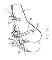
- FIG. 1is a broken perspective view of the distal femur with an anchoring device according to the invention
- FIG. 2is a side elevational view of the anchoring device installed in the distal femur
- FIG. 3is a perspective view of the anchoring device installed in the distal femur with a three-way alignment guide according to the invention not yet attached to the anchoring device;
- FIG. 4is a view similar to FIG. 3 showing the alignment guide attached to the anchoring device
- FIG. 5is a perspective view showing a first embodiment of a resection guide according to the invention not yet attached to the three-way alignment guide;
- FIG. 6is a perspective view showing a first embodiment of a resection guide according to the invention attached to the three-way alignment guide;
- FIG. 7is a side elevational view showing a first embodiment of a resection guide according to the invention attached to the three-way alignment guide;
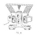
- FIGS. 8 and 8Aare perspective views of an anterior-posterior sizer
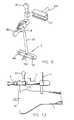
- FIG. 9is an exploded perspective view of the distal-proximal medial-lateral positioning guide, medial-lateral cam lock, anterior-posterior positioning guide, and femoral sizing block bushing;
- FIG. 10is a plan view of the distal-proximal medial-lateral positioning guide, medial-lateral cam lock, anterior-posterior positioning guide, and femoral sizing block bushing coupled to the alignment guide;
- FIGS. 11 and 12are perspective views of the distal-proximal medial-lateral positioning guide, medial-lateral cam lock, anterior-posterior positioning guide, and femoral sizing block bushing coupled to the alignment guide;
- FIG. 13is a side elevation view of the distal-proximal medial-lateral positioning guide, medial-lateral cam lock, anterior-posterior positioning guide, and femoral sizing block bushing coupled to the alignment guide;
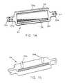
- FIGS. 14 and 15are perspective views of a femoral cutting guide
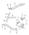
- FIG. 16is an exploded perspective view of a pivotal 5-in-1 positional alignment jig and five-way alignment guide;
- FIGS. 17-19are perspective views of the pivotal 5-in-1 positional alignment jig and five-way alignment guide coupled to the anchoring device;
- FIG. 20is a perspective view of a pair of diodes coupled to the epicondylar region of the femur.
- FIG. 21is a perspective view of a 5-in-one cutting block mounted on the diodes.
- an anchoring device 10is installed in the bone 1 in a region proximal to the lateral anterior cortex and within the incision.
- the location for the anchoring devicemay be chosen by eye or with the aid of the tracking/navigation software, with an emphasis on paralleling the anchoring device body to the sagital plane.
- the anchoring device 10is a pin which is screwed into the bone. Other anchoring devices such as plates could be used, however.
- the alignment guide 12With the anchoring device 10 in place, the alignment guide 12 is lowered on to it as shown in FIGS. 3-5 .
- the alignment guide 12has three cam locks 12 a, 12 b, 12 c.
- the cam lock 12 aallows the alignment guide to be adjusted according to flexion-extension angle relative to the anchoring device 10 .
- the cam lock 12 ballows the alignment guide to be adjusted according to varus-valgus angle relative to the anchoring device 10 .
- the cam lock 12 copens the end of the alignment device to receive the resection guide 14 shown in FIGS. 5-7 and also allows for distal-proximal adjustment.
- the resection guide 14has a cutting guide surface 14 a, an attachment rod 14 b, a pair of connectors 14 c, 14 d for connecting trackers (not shown), a pair of rotatable pin guides 14 e, 14 f, and a pair of fail safe mounting bores 14 g, 14 h.
- the resection guide 14is attached to the alignment guide 12 by opening cam lock 12 c and inserting the attachment rod 14 b into the alignment guide. It will be appreciated that the cam lock 12 c allows proximal-distal positioning of the resection guide 14 .
- a trackeris attached to the guide 14 .
- the first cam lock 12 ais opened and the resection guide is moved in the varus-valgus plane until the navigation software indicates the proper alignment.
- the cam lock 12 ais then locked.
- Cam lock 12 bis unlocked and the resection guide is moved in the flexion-extension plane until the navigation software indicates the proper alignment.
- the cam lock 12 bis then locked.
- the cam lock 12 cis opened and the resection guide is positioned in the proximal-distal plane until the navigation software indicates the proper alignment.
- the cam lock 12 cis then locked.
- the resection guideWith the resection guide properly located, it may be affixed to the bone with pins (not shown) via the rotatable pin guides 14 e, 14 f.
- the pin guidesare rotatable so that the practitioner may choose the best site for inserting a pin.
- the next step in the procedureis to resect the distal end of the femur using the resection guide 14 .
- the stepsmay need to be repeated to tune out error introduced by the misaligned anchor pin.
- One possible solutionis to install the pin with a drill having an attached tracker thereby allowing the navigation software to guide the placement of the pin.
- the femuris sized using either of the following methods:
- FIGS. 8 and 8 aAn exemplary sizing guide 15 is shown in FIGS. 8 and 8 a.
- the adjustable A-P sizer 15sets internal-external rotation and also allows an AP movement of +/ ⁇ 2 mm. This instrument is used after the femoral distal cut is performed.
- the feet 15 a, 15 bare inserted under the posterior condyles.
- the jigis allowed to move through six degrees either internally or externally as shown by the indicia between the letters “L” and “R”.
- a blade runneris introduced into one of the slots (labeled in 3, 5, 7, 9, 11, and 13 mm).
- the slot selectedis the one that gives the required run-out anteriorly. If the surgeon is in between sizes, if he goes down a size, he will notch the femur, or if he moves up a size he will leave a gap. The jig allows the surgeon to obtain the optimal position.
- the appropriately sized femoral sizing block bushing 16is attached to the alignment guide 12 using an anterior-posterior positioning guide 18 having a cam lock 18 a, a medial-lateral cam lock 20 , and a distal-proximal medial-lateral positioning guide 22 .
- the bushing 16has a vertical shaft 16 a, a pair of drill guides 16 b, 16 c, and a tracker coupling 16 d.
- the vertical shaft 16 ais inserted into the anterior-posterior positioning guide 18 which is coupled to the medial-lateral cam lock 20 which is slidably coupled to the distal-proximal medial-lateral positioning guide 22 .
- a tracker(not shown) is coupled to the coupling 16 d.
- the distal-proximal positionis set by manually presenting the bushing 16 to the resected face of the femur.
- the internal-external rotationis navigated and the cam lock is locked on the positioning guide.
- the medial-lateral positioning of the bushingis navigated and locked using the medial-lateral cam lock 20 .
- anterior-posterior positioningis navigated and locked with the cam lock 18 a. Verification of the navigated position is done in conjunction with the screens on the computer. Once satisfied with the navigated position, two holes are drilled through the drill guides 16 b, 16 c. The complete anchoring mechanism is removed and the appropriate femoral cutting block is attached.
- FIGS. 14 and 15illustrate an exemplary cutting block 24 .
- the cutting block 24has a pair of pins 24 a, 24 b which are impacted into the holes drilled with the bushing 16 (described above).
- Additional fixation holes 24 c - 24 fare provided for optional fixation with pins.
- the cutting guidehas four guiding surfaces: the anterior cut guiding surface 24 g, the posterior cut guiding surface 24 h, the anterior chamfer cut guiding surface 24 i, and the posterior chamfer cut guiding surface 24 j. After these four cuts are made, the cutting block is removed and the femur is near ready for accepting the prosthesis.
- FIGS. 16 through 21A second embodiment of the methods and tools of the invention is illustrated with reference to FIGS. 16 through 21 .
- the second embodimentutilized the same anchoring device 10 , alignment guide 12 , and the alignment devices 18 , 20 , 22 with a minor alteration.
- the anterior-posterior alignment device 18 ′ shown in the Figureshas its cam lock 18 ′ a oriented in a slightly different position than the cam lock 18 a on the alignment device 18 .
- the devices 12 , 18 ′, 20 , and 22are assembled to provide what amounts to a six-way alignment guide.
- a pivotal 5-in-1 positional alignment jigis provided which includes the components 26 , 28 , and 30 .
- Component 26is a T-bar having a vertical shaft 26 a, a lateral arm 26 b and a medial arm 26 c.
- Component 28is a medial drilling guide arm having a mounting hole 28 a, a set screw 28 b, and drill guides 28 c.
- Component 30is a lateral drilling guide arm having a mounting hole 30 a, a set screw 30 b, and drill guides 30 c.
- FIGS. 17-19After the femur is digitized as described above with reference to the first embodiment, the components are assembled as shown in FIGS. 17-19 .
- a tracker(not shown) is attached to one of the set screws 28 b, 30 b.
- the medial and lateral drilling guides 28 , 30are positioned in the following directions in the following order: varus-valgus, flexion-extension, internal-external rotation, distal-proximal, and anterior-posterior directions.
- the sequential locking of the guidebegins with flexion-extension.
- the cam lock 12 bis opened and the jig is navigated until the recommended position is reached. Once reached, the flexion-extension cam lock 12 b is engaged.
- varus-valgus lock 12 ais opened and flexion-extension is navigated.
- the jigis navigated until the recommended position is reached. Once attained, the varus-valgus cam lock 12 a is engaged.
- internal-external rotationis navigated.
- the cam lock 12 cis opened and the jig is navigated until the recommended positions are reached.
- anterior-posterior positioningis navigated.
- the cam lock 18 ais opened and the jig is navigated until the recommended position is reached.
- the anterior-posterior cam lock 18 ais engaged.
- the medial-lateral positioningis not performed until the 5-in-1 cutting guide is attached as described below with reference to FIG. 21 .
- a pair of diodes 32 , 34are installed in the epicondylar region with screws (not shown), in the holes which were drilled in the previous step, using a screwdriver 36 .
- a 5-in-1 cutting guide 38is mounted on the diodes as described in previously incorporated application Ser. No. 09/746,800. Prior to fixing the cutting guide with pins, the medial-lateral position of the guide is fine tuned by the surgeon. The 5-in-1 cutting block is then pinned in position and is used to perform all of the femoral cuts as described in previously incorporated application Ser. No. 09/746,800.
Landscapes
- Health & Medical Sciences (AREA)
- Life Sciences & Earth Sciences (AREA)
- Surgery (AREA)
- Nuclear Medicine, Radiotherapy & Molecular Imaging (AREA)
- Medical Informatics (AREA)
- General Health & Medical Sciences (AREA)
- Oral & Maxillofacial Surgery (AREA)
- Engineering & Computer Science (AREA)
- Biomedical Technology (AREA)
- Heart & Thoracic Surgery (AREA)
- Dentistry (AREA)
- Molecular Biology (AREA)
- Animal Behavior & Ethology (AREA)
- Orthopedic Medicine & Surgery (AREA)
- Public Health (AREA)
- Veterinary Medicine (AREA)
- Pathology (AREA)
- Radiology & Medical Imaging (AREA)
- Physical Education & Sports Medicine (AREA)
- Transplantation (AREA)
- Surgical Instruments (AREA)
- Prostheses (AREA)
Abstract
Description
This application is related to patent application Ser. No. 09/811,272, filed Mar. 17, 2001, entitled “Tools Used In Performing Femoral And Tibial Resection In Knee Surgery”; patent application Ser. No. 09/811,043, filed Mar. 17, 2001, entitled “Methods Used In Performing Femoral And Tibial Resection In Knee Surgery”; patent application Ser. No. 09/811,042, filed Mar. 17, 2001, entitled “Systems Used In Performing Femoral And Tibial Resection In Knee Surgery”; patent application Ser. No. 09/811,318, filed Mar. 17, 2001, entitled “Apparatus Used In Performing Femoral And Tibial Resection In Knee Surgery” and patent application Ser. No. 09/746,800 filed Dec. 23, 2000, entitled “Methods and Tools For Femoral Resection In Primary Knee Surgery”, the complete disclosures of which are hereby incorporated by reference herein.
1. Field of the Invention
The invention relates to methods and tools used in knee arthroplasty. More particularly, the invention relates to methods and tools used in knee surgery where artificial femoral and tibial components are installed.
2. Brief Description of the Prior Art
Total knee arthroplasty involves the replacement of portions of the patellar, femur and tibia with artificial components. In particular, a proximal portion of the tibia and a distal portion of the femur are cut away (resected) and replaced with artificial components.
As used herein, when referring to bones or other body parts, the term “proximal” means closest to the heart and the term “distal” means more distant from the heart. When referring to tools and instruments, the term “proximal” means closest to the practitioner and the term “distal” means distant from the practitioner.
There are several types of knee prostheses known in the art. One type is sometimes referred to as a “resurfacing type”. In these prostheses, the articular surface of the distal femur and proximal tibia are “resurfaced” with respective metal and plastic condylar-type articular bearing components.
The femoral component is a metallic alloy construction (cobalt-chrome alloy or 6A14V titanium alloy) and provides medial and lateral condylar bearing surfaces of multi-radius design of similar shape and geometry as the natural distal femur or femoral-side of the knee joint.
One important aspect of these procedures is the correct resection of the distal femur and proximal tibia. These resections must provide planes which are correctly angled in order to properly accept the prosthetic components. In particular, the resection planes must be correctly located relative to three parameters: proximal-distal location, varus-valgus angle, and flexion-extension angle.
Moreover, following distal resection, the femur must be shaped with the aid of a cutting block. The cutting block must be correctly located relative to internal-external rotation, medial-lateral position, and anterior-posterior position.
Recently, various computerized systems have been introduced to aid the practitioner during different surgical procedures. A typical system is described in the attached Appendix.
These systems include multiple video cameras which are deployed above the surgical site and a plurality of dynamic reference frame (DRF) devices, also known as trackers, which are attached to body parts and surgical instruments. The trackers are generally LED devices which are visible to the cameras. Using software designed for a particular surgical procedure, a computer receiving input from the cameras guides the placement of surgical instruments.
The prior art instruments used for determining the correct planes for tibial and femoral resection in total knee arthroplasty are not well suited for use with computerized systems. The known tools utilize either intra-medullary alignment or extra-medullary alignment and adjustment of the degrees of freedom simultaneously is difficult or impossible. Moreover, in order to be useful with computer aided navigation systems, trackers must be attached to the tools. Existing tools do not permit the attachment of trackers.
It is therefore an object of the invention to provide methods and tools for performing femoral resection.
It is also an object of the invention to provide methods and tools for femoral resection which allow location of a cutting guide relative to six parameters.
It is another object of the invention to provide methods and tools for femoral resection which are infinitely adjustable.
It is still another object of the invention to provide methods and tools for femoral resection which are adapted to be used with computer aided navigation systems.
In accord with these objects which will be discussed in detail below, the tools according to a first embodiment of the present invention include an anchoring device for attachment to the femur and, a three-way alignment guide attachable to the anchoring device and adjustable relative to three parameters, a resection guide attachable to the alignment guide and equipped with couplings for trackers, an adjustable anterior-posterior sizer, a distal-proximal medial-lateral positioning guide, a medial-lateral cam lock, an anterior-posterior positioning guide, a femoral sizing block bushing, and femoral cutting guide.
The tools according to a second embodiment of the present invention include an anchoring device for attachment to the femur and, a six-way alignment guide attachable to the anchoring device and adjustable relative to six parameters, a pivotal 5-in-1 positional alignment jig attachable to the alignment guide and equipped with couplings for trackers, a pair of mounting diodes attachable to the epicondylar region of the femur, and a 5-in-1 cutting guide mountable on the diodes.
A first embodiment of the methods of the invention includes operating the computer aided navigation apparatus in the conventional manner including attaching one or more trackers to the bone to be resected; choosing a location for the anchoring device with or without guidance from the computer and installing the anchoring device; attaching the three-way alignment guide to the anchoring device; attaching a resection guide to the alignment guide; attaching one or two trackers to the resection guide; locating the resection guide with the aid of the alignment guide and the computer; fixing the resection guide to the bone with pins through the rotatable pin guides; and resecting the bone.
After the bone is resected, the adjustable anterior-posterior sizer is used to size the femur.
Next, the distal-proximal medial-lateral positioning guide, medial-lateral cam lock, anterior-posterior positioning guide, and femoral sizing block bushing are attached to the alignment guide.
The distal-proximal medial-lateral positioning guide, medial-lateral cam lock, and anterior-posterior positioning guide, when attached to the three-way guide, convert the three-way guide into a six-way guide. A tracker is preferably attached to the femoral sizing block bushing. The position of the bushing is adjusted in proximal-distal, varus-valgus, medial-lateral, and anterior-posterior directions. Two holes are drilled using the bushing as a guide. The femoral cutting guide is attached to the holes and the anterior and posterior cuts and chamfer cuts are made.
A second embodiment of the methods of the invention includes operating the computer aided navigation apparatus in the conventional manner including attaching one or more trackers to the bone to be resected; choosing a location for the anchoring device with or without guidance from the computer and installing the anchoring device; attaching the six-way alignment guide to the anchoring device; attaching the pivotal 5-in-1 positional alignment jig to the alignment guide; attaching a tracker to the jig; positioning the jig in the varus-valgus, flexion-extension, internal-external rotation, distal-proximal, and anterior-posterior directions; drilling four holes in the epicondylar region using the jig as a guide; removing the jig, the alignment guide, and the anchoring device; installing a pair of diodes in the epicondylar region with screws in the holes; and mounting the 5-in-1 cutting guide on the diodes.
The 5-in-1 cutting guide is then used to perform all of the femoral cuts as described in previously incorporated application Ser. No. 09/746,800.
The attached ten page Appendix describes the parts and assembly of a computer navigation system suitable for use with the invention.
Turning now to the Figures, the apparatus of the invention will be best understood by a description of the methods of the invention with reference to the Figures. As shown inFIGS. 1 and 2 ananchoring device 10 is installed in thebone 1 in a region proximal to the lateral anterior cortex and within the incision. The location for the anchoring device may be chosen by eye or with the aid of the tracking/navigation software, with an emphasis on paralleling the anchoring device body to the sagital plane. As shown in the Figures, the anchoringdevice 10 is a pin which is screwed into the bone. Other anchoring devices such as plates could be used, however.
With theanchoring device 10 in place, thealignment guide 12 is lowered on to it as shown inFIGS. 3-5 . As seen best inFIG. 5 , thealignment guide 12 has three cam locks12a,12b,12c.The cam lock12aallows the alignment guide to be adjusted according to flexion-extension angle relative to theanchoring device 10. The cam lock12ballows the alignment guide to be adjusted according to varus-valgus angle relative to theanchoring device 10. The cam lock12copens the end of the alignment device to receive theresection guide 14 shown inFIGS. 5-7 and also allows for distal-proximal adjustment.
Referring now toFIGS. 5-7 , theresection guide 14 has a cutting guide surface14a,an attachment rod14b,a pair of connectors14c,14dfor connecting trackers (not shown), a pair of rotatable pin guides14e,14f,and a pair of fail safe mounting bores14g,14h.Theresection guide 14 is attached to thealignment guide 12 by opening cam lock12cand inserting the attachment rod14binto the alignment guide. It will be appreciated that the cam lock12callows proximal-distal positioning of theresection guide 14. After theresection guide 14 is attached to thealignment device 12, a tracker is attached to theguide 14.
With the tracker attached, the first cam lock12ais opened and the resection guide is moved in the varus-valgus plane until the navigation software indicates the proper alignment. The cam lock12ais then locked. Cam lock12bis unlocked and the resection guide is moved in the flexion-extension plane until the navigation software indicates the proper alignment. The cam lock12bis then locked.
Lastly, the cam lock12cis opened and the resection guide is positioned in the proximal-distal plane until the navigation software indicates the proper alignment. The cam lock12cis then locked. With the resection guide properly located, it may be affixed to the bone with pins (not shown) via the rotatable pin guides14e,14f.The pin guides are rotatable so that the practitioner may choose the best site for inserting a pin. The next step in the procedure is to resect the distal end of the femur using theresection guide 14.
Those skilled in the art will appreciate that if theanchor pin 10 is not substantially parallel to the sagital plane, the steps may need to be repeated to tune out error introduced by the misaligned anchor pin. One possible solution is to install the pin with a drill having an attached tracker thereby allowing the navigation software to guide the placement of the pin.
Following distal femoral resection, the femur is sized using either of the following methods:
1) Conventional sizing using either the Monogram or X-celerate sizing guides is performed. Surface digitization of the posterior condyles must be performed by the surgeon using the pointer by running the pointer tip over the posterior condylar bone and/or cartilage. The sizing guide is placed flush on the resected distal femur with the posterior skids against the posterior condyles. Either the sizing stylus or blade runner (or saw blade) is used to measure the most prominent aspect of the femoral lateral cortex. The femoral sizing block bushing can now be navigated.
An exemplary sizingguide 15 is shown inFIGS. 8 and 8 a.Theadjustable A-P sizer 15 sets internal-external rotation and also allows an AP movement of +/−2 mm. This instrument is used after the femoral distal cut is performed. The feet15a,15bare inserted under the posterior condyles. The jig is allowed to move through six degrees either internally or externally as shown by the indicia between the letters “L” and “R”.
A blade runner is introduced into one of the slots (labeled in 3, 5, 7, 9, 11, and 13 mm). The slot selected is the one that gives the required run-out anteriorly. If the surgeon is in between sizes, if he goes down a size, he will notch the femur, or if he moves up a size he will leave a gap. The jig allows the surgeon to obtain the optimal position.
2) Alternatively, software algorithms are used to size the femur. Surface digitization of the trochlear groove (patella track) and posterior condyles are performed by the surgeon using the pointer by running the pointer tip over the posterior condylar bone and/or cartilage. Digitized data is analyzed in the sagital plane. Direct correlation to (or matching of) the correct femoral component is achieved via the software coding/algorithms. The surgeon will be able to visualize the matching on the operating room computer monitor (graphical interface). Sizing is complete using solely digitization methods. The femoral sizing block bushing can now be navigated.
Turning now toFIGS. 9-13 , after the distal femur is resected and sizing is completed, the appropriately sized femoral sizingblock bushing 16 is attached to thealignment guide 12 using an anterior-posterior positioning guide 18 having a cam lock18a,a medial-lateral cam lock 20, and a distal-proximal medial-lateral positioning guide 22. Thebushing 16 has a vertical shaft16a,a pair of drill guides16b,16c,and a tracker coupling16d.The vertical shaft16ais inserted into the anterior-posterior positioning guide 18 which is coupled to the medial-lateral cam lock 20 which is slidably coupled to the distal-proximal medial-lateral positioning guide 22.
A tracker (not shown) is coupled to the coupling16d.Using the cam locks, the distal-proximal position is set by manually presenting thebushing 16 to the resected face of the femur. The internal-external rotation is navigated and the cam lock is locked on the positioning guide. The medial-lateral positioning of the bushing is navigated and locked using the medial-lateral cam lock 20. Finally, anterior-posterior positioning is navigated and locked with the cam lock18a.Verification of the navigated position is done in conjunction with the screens on the computer. Once satisfied with the navigated position, two holes are drilled through the drill guides16b,16c.The complete anchoring mechanism is removed and the appropriate femoral cutting block is attached.
Additional fixation holes24c-24fare provided for optional fixation with pins. The cutting guide has four guiding surfaces: the anterior cut guiding surface24g,the posteriorcut guiding surface 24h,the anterior chamfercut guiding surface 24i,and the posterior chamfercut guiding surface 24j.After these four cuts are made, the cutting block is removed and the femur is near ready for accepting the prosthesis.
A second embodiment of the methods and tools of the invention is illustrated with reference toFIGS. 16 through 21 . The second embodiment utilized thesame anchoring device 10,alignment guide 12, and thealignment devices posterior alignment device 18′ shown in the Figures has itscam lock 18′aoriented in a slightly different position than the cam lock18aon thealignment device 18. According to this embodiment, thedevices components Component 26 is a T-bar having a vertical shaft26a,a lateral arm26band a medial arm26c.Component 28 is a medial drilling guide arm having a mounting hole28a,a set screw28b,and drill guides28c.Component 30 is a lateral drilling guide arm having a mounting hole30a,a set screw30b,and drill guides30c.
After the femur is digitized as described above with reference to the first embodiment, the components are assembled as shown inFIGS. 17-19 . A tracker (not shown) is attached to one of the set screws28b,30b.
Using the various CAM locks, the medial and lateral drilling guides28,30 are positioned in the following directions in the following order: varus-valgus, flexion-extension, internal-external rotation, distal-proximal, and anterior-posterior directions.
More particularly, the sequential locking of the guide begins with flexion-extension. The cam lock12bis opened and the jig is navigated until the recommended position is reached. Once reached, the flexion-extension cam lock12bis engaged.
Next, varus-valgus lock12ais opened and flexion-extension is navigated. The jig is navigated until the recommended position is reached. Once attained, the varus-valgus cam lock12ais engaged. Next, internal-external rotation is navigated.
The cam lock12cis opened and the jig is navigated until the recommended positions are reached.
Once attained, the internal-external rotation and distal-proximal translation are engaged. Next, anterior-posterior positioning is navigated. The cam lock18ais opened and the jig is navigated until the recommended position is reached. Once attained, the anterior-posterior cam lock18ais engaged. The medial-lateral positioning is not performed until the 5-in-1 cutting guide is attached as described below with reference toFIG. 21 .
After the drilling guides are positioned, four holes are drilled into the epicondylar region using the drill guides28c,30c.All of the devices are then removed from the femur.
Referring now toFIG. 20 , a pair ofdiodes screwdriver 36.
Turning now toFIG. 21 , a 5-in-1cutting guide 38 is mounted on the diodes as described in previously incorporated application Ser. No. 09/746,800. Prior to fixing the cutting guide with pins, the medial-lateral position of the guide is fine tuned by the surgeon. The 5-in-1 cutting block is then pinned in position and is used to perform all of the femoral cuts as described in previously incorporated application Ser. No. 09/746,800.
There have been described and illustrated herein methods and tools for resection of the distal femur. While particular embodiments of the invention have been described, it is not intended that the invention be limited thereto, as it is intended that the invention be as broad in scope as the art will allow and that the specification be read likewise. For example, the first two positioning steps may be reversed in sequence, provided that the navigation software is suitable modified. Moreover, the clamps on the alignment guides need not be cam locks, but could be other types of clamps. Although the apparatus has been described as separate pieces (e.g. the anchor, the alignment guide, and the resection guide), it could be two pieces or a single piece. In general, the methods and tools of the invention could be used with other joints other than the knee. It is believed that the methods and tools could be used in arthroplasty of the hip, shoulder, elbow, etc.
Claims (15)
1. An apparatus for use during arthroplasty for guiding the resection of a bone having a long axis, comprising:
an anchoring pin for anchoring the apparatus to the bone, said anchoring pin oriented transversely to the long axis of the bone;
a first cam lock having a rod member at a first end and a split bore at a second end for slidably and rotationally receiving the pin, a diameter of the split bore being reduced by actuation of a first cam lever forming part of the first cam lock;
a first split tubular member having a bore with a first longitudinal axis, a second cam lock located at a first end of the first split tubular member, the rod member slidably and rotationally received within the bore at a first end of the first split tubular member, a diameter of the first split tubular member bore reduced by the actuation of a second cam lever forming part of the second cam lock;
a third cam lock located at the second end of the first split tubular member, a diameter of the first split tubular member bore at a second end thereof reduced by the actuation of a third cam lever forming part of the third cam lock, a positioning guide having a rod thereon mounted in the second end of the first split tubular member and locked in the bore by the third cam lock, the positioning guide having a track thereon extending in a plane perpendicular to the longitudinal axis of the first split tubular member bore, the track having a fourth cam lock, the track slidably receiving an element having a fifth cam lock having a second split tubular member having a bore capable of being reduced by actuation of a fifth cam lever, the element having the fifth cam lock is slidable on the track along a plane perpendicular to the longitudinal axis of the first split tubular member and capable of being locked in the track by the fourth cam lock, a guide having a rod slidably mounted in the second split tubular member bore and capable of being locked in the bore of the fifth cam lock by the fifth cam lever, the guide slidable in a plane parallel to the plane of the track and perpendicular to the first longitudinal axis of the split tubular member, the second direction perpendicular to the first direction, said apparatus providing six degrees of freedom, wherein said six degrees of freedom include three rotations and three orthogonal translations.
2. The apparatus according toclaim 1 wherein said six degrees of freedom include flexion-extension, varus-valgus, and proximal-distal.
3. The apparatus according toclaim 2 wherein said six degrees of freedom include flexion-extension, varus-valgus, internal-external rotation, proximal-distal, medial-lateral, and anterior-posterior.
4. The apparatus according toclaim 1 wherein said guide includes means for attaching a computer navigation tracker.
5. The apparatus according toclaim 1 wherein said guide includes a pair of arms having guide holes adapted to guide drilling into the epicondylar region of a femur.
6. The apparatus according toclaim 5 wherein said guide includes a T-shaped component and said arms are adapted to be coupled to said T-shaped component.
7. The apparatus according toclaim 1 wherein said guide is adapted to guide the drilling of two holes in the distal femur.
8. The apparatus ofclaim 1 wherein said anchoring means is oriented substantially parallel to the sagital plane.
9. A set of tools for guiding the resection of a bone during arthroplasty, said set of tools comprising:
a guide bushing defining two spaced apart guide holes, said guide bushing having an orthogonal stem for coupling to an alignment device and a coupling for coupling a tracker to the bushing, the guide bushing moveable in a direction with respect to the stem transverse to a longitudinal axis of the stem;
an alignment device having six degrees of freedom wherein three are rotational and three are orthogonal translations, said alignment device being adapted to couple to said stem and couple to an anchoring device;
the alignment device comprising:
a first cam lock having a rod member at a first end and a split bore at a second end for slidably and rotationally receiving the anchoring device coupled to a bone, a diameter of the split bore being reduced by actuation of a first cam lever forming part of the first cam lock;
a first split tubular member having a bore with a first longitudinal axis, a second cam lock located at a first end of the first split tubular member, the rod member slidably and rotationally received within the bore at a first end of the first split tubular member, a diameter of the first split tubular member bore reduced by the actuation of a second cam lever forming part of the second cam lock;
the guide bushing orthogonal stem slidably and rotationally received within a bore at a second end of the first split tubular member; and
a third cam lock located at the second end of the first split tubular member, a diameter of the first split tubular member bore at the second end reduced by the actuation of a third cam lever forming part of the third cam lock, the guide bushing having a rod thereon mounted in the second end of the first split tubular member and locked in the bore by the third cam lock, the positioning guide having a track thereon extending in a plane perpendicular to the longitudinal axis of the first split tubular member bore, the track having a fourth cam lock, the track slidably receiving an element having a fifth cam lock having a second split tubular member having a bore capable of being reduced by actuation of a fifth cam lever, the element having the fifth cam lock is slidable on the track along a plane perpendicular to the longitudinal axis of the first split tubular member bore and capable of being locked in the track by the fourth cam lock, a guide having a rod slidably mounted in the second split tubular member bore and capable of being locked in the bore of the fifth cam lock by the fifth cam lever, the guide slidable in a plane parallel to the plane of the track and perpendicular to the first longitudinal axis of the split tubular member, the second direction perpendicular to the first direction.
10. The set of tools according toclaim 9 wherein said guide is adapted to guide the drilling of holes in the distal femur.
11. The set of tools according toclaim 9 wherein said alignment device has six degrees of freedom.
12. The set of tools according toclaim 9 wherein said guide bushing includes a medial guide hole and a lateral guide hole, said medial guide hole for drilling into the medial condylar region, and said lateral guide bushing for drilling into the lateral condylar region.
13. A set of tools for guiding the resection of a bone during arthroplasty, said set of tools comprising:
a resection guide comprising a guide bushing having an orthogonal stem for coupling to an alignment device and a coupling for coupling a tracker to the guide;
an alignment device for aligning the resection guide having three rotational degrees of freedom and three orthogonal translational degrees of freedom comprising:
a first cam lock having a rod member at a first end and a split bore at a second end for slidably and rotationally receiving a pin extending into a bone, a diameter of the split bore being reduced by actuation of a first cam lever forming part of the first cam lock;
a first split tubular member having a bore with a first longitudinal axis, a second cam lock located at a first end of the first split tubular member, the rod member slidably and rotationally received within the bore at a first end of the first split tubular member, a diameter of the first split tubular member bore reduced by the actuation of a second cam lever forming part of the second cam lock;
the guide bushing orthogonal stem slidably and rotationally received within a bore at a second end of the first split tubular member, the guide bushing movable in a direction with respect to the stem transverse to a longitudinal axis of the stem; and
a third cam lock located at the second end of the first split tubular member, a diameter of the split tubular member bore at the second end reduced by the actuation of a third cam lever forming part of the third cam lock, the guide bushing having a positioning guide having a rod thereon mounted in the second end of the first split tubular member and locked in the bore by the third cam lock, the positioning guide having a track thereon extending in a plane perpendicular to the longitudinal axis of the first split tubular member bore, the track having a fourth cam lock, the track slidably receiving an element having a fifth cam lock having a second split tubular member having a bore capable of being reduced by actuation of a fifth cam lever, the element having the fifth cam lock is slidable on the track along a plane perpendicular to the first longitudinal axis of the first split tubular member and capable of being locked in the track by the fourth cam lock, a guide having a rod slidably mounted in the second split tubular member bore and capable of being locked in the bore of the fifth cam lock by the fifth cam lever, the guide slidable in a plane parallel to the plane of the track and perpendicular to the first longitudinal axis of the split tubular member, the second direction perpendicular to the first direction.
14. The set of tools according toclaim 13 wherein said guide is adapted to guide the drilling of holes in the distal femur.
15. The set of tools according toclaim 13 wherein said guide is a guide bushing which includes a medial guide hole and a lateral guide hole, said medial guide bushing hole for drilling into the medial condylar region, and said lateral guide bushing hole for drilling into the lateral condylar region.
Priority Applications (5)
| Application Number | Priority Date | Filing Date | Title |
|---|---|---|---|
| US09/974,524US7618421B2 (en) | 2001-10-10 | 2001-10-10 | Tools for femoral resection in knee surgery |
| CA002403544ACA2403544C (en) | 2001-10-10 | 2002-09-17 | Methods and tools for femoral resection in knee surgery |
| EP02292498AEP1302167A3 (en) | 2001-10-10 | 2002-10-10 | Tools for femoral resection in knee surgery |
| JP2002297244AJP2003175046A (en) | 2001-10-10 | 2002-10-10 | Method and apparatus for femoral resection in knee surgery |
| US12/584,686US7931655B2 (en) | 2001-10-10 | 2009-09-10 | Methods and tools for femoral resection in knee surgery |
Applications Claiming Priority (1)
| Application Number | Priority Date | Filing Date | Title |
|---|---|---|---|
| US09/974,524US7618421B2 (en) | 2001-10-10 | 2001-10-10 | Tools for femoral resection in knee surgery |
Related Child Applications (1)
| Application Number | Title | Priority Date | Filing Date |
|---|---|---|---|
| US12/584,686DivisionUS7931655B2 (en) | 2001-10-10 | 2009-09-10 | Methods and tools for femoral resection in knee surgery |
Publications (2)
| Publication Number | Publication Date |
|---|---|
| US20030069585A1 US20030069585A1 (en) | 2003-04-10 |
| US7618421B2true US7618421B2 (en) | 2009-11-17 |
Family
ID=25522132
Family Applications (2)
| Application Number | Title | Priority Date | Filing Date |
|---|---|---|---|
| US09/974,524Expired - LifetimeUS7618421B2 (en) | 2001-10-10 | 2001-10-10 | Tools for femoral resection in knee surgery |
| US12/584,686Expired - Fee RelatedUS7931655B2 (en) | 2001-10-10 | 2009-09-10 | Methods and tools for femoral resection in knee surgery |
Family Applications After (1)
| Application Number | Title | Priority Date | Filing Date |
|---|---|---|---|
| US12/584,686Expired - Fee RelatedUS7931655B2 (en) | 2001-10-10 | 2009-09-10 | Methods and tools for femoral resection in knee surgery |
Country Status (4)
| Country | Link |
|---|---|
| US (2) | US7618421B2 (en) |
| EP (1) | EP1302167A3 (en) |
| JP (1) | JP2003175046A (en) |
| CA (1) | CA2403544C (en) |
Cited By (49)
| Publication number | Priority date | Publication date | Assignee | Title |
|---|---|---|---|---|
| US20040169673A1 (en)* | 2002-08-19 | 2004-09-02 | Orthosoft Inc. | Graphical user interface for computer-assisted surgery |
| US20070073305A1 (en)* | 2003-06-19 | 2007-03-29 | Lionberger David R | Cutting guide apparatus and surgical method for use in knee arthroplasty |
| US20070239166A1 (en)* | 2004-05-11 | 2007-10-11 | Mcguire David A | Surgical Device for Anterolateral and Posterolateral Reconstruction |
| US20080228189A1 (en)* | 2007-03-13 | 2008-09-18 | Biomet Manufacturing Corp | Distal femoral cutting guide |
| US20090222010A1 (en)* | 2005-06-03 | 2009-09-03 | Lafosse Laurent | Instrument for use in a joint replacement procedure |
| US20100131021A1 (en)* | 2006-11-15 | 2010-05-27 | Depuy International Limited | Locating a bone axis |
| USD642263S1 (en) | 2007-10-25 | 2011-07-26 | Otismed Corporation | Arthroplasty jig blank |
| US8160345B2 (en) | 2008-04-30 | 2012-04-17 | Otismed Corporation | System and method for image segmentation in generating computer models of a joint to undergo arthroplasty |
| US8221430B2 (en) | 2007-12-18 | 2012-07-17 | Otismed Corporation | System and method for manufacturing arthroplasty jigs |
| US8311306B2 (en) | 2008-04-30 | 2012-11-13 | Otismed Corporation | System and method for image segmentation in generating computer models of a joint to undergo arthroplasty |
| US20130053855A1 (en)* | 2011-08-29 | 2013-02-28 | Morton Bertram, III | Bony balancing apparatus and method for total knee replacement |
| US8460303B2 (en) | 2007-10-25 | 2013-06-11 | Otismed Corporation | Arthroplasty systems and devices, and related methods |
| US8460302B2 (en) | 2006-12-18 | 2013-06-11 | Otismed Corporation | Arthroplasty devices and related methods |
| US8480679B2 (en) | 2008-04-29 | 2013-07-09 | Otismed Corporation | Generation of a computerized bone model representative of a pre-degenerated state and useable in the design and manufacture of arthroplasty devices |
| US8545509B2 (en) | 2007-12-18 | 2013-10-01 | Otismed Corporation | Arthroplasty system and related methods |
| US8617175B2 (en) | 2008-12-16 | 2013-12-31 | Otismed Corporation | Unicompartmental customized arthroplasty cutting jigs and methods of making the same |
| US8617171B2 (en) | 2007-12-18 | 2013-12-31 | Otismed Corporation | Preoperatively planning an arthroplasty procedure and generating a corresponding patient specific arthroplasty resection guide |
| US8715291B2 (en) | 2007-12-18 | 2014-05-06 | Otismed Corporation | Arthroplasty system and related methods |
| US8737700B2 (en) | 2007-12-18 | 2014-05-27 | Otismed Corporation | Preoperatively planning an arthroplasty procedure and generating a corresponding patient specific arthroplasty resection guide |
| US8734455B2 (en) | 2008-02-29 | 2014-05-27 | Otismed Corporation | Hip resurfacing surgical guide tool |
| US20140189508A1 (en)* | 2012-12-31 | 2014-07-03 | Mako Surgical Corp. | Systems and methods for guiding a user during surgical planning |
| US8777875B2 (en) | 2008-07-23 | 2014-07-15 | Otismed Corporation | System and method for manufacturing arthroplasty jigs having improved mating accuracy |
| US8784495B2 (en) | 2000-01-14 | 2014-07-22 | Bonutti Skeletal Innovations Llc | Segmental knee arthroplasty |
| US8801719B2 (en) | 2002-05-15 | 2014-08-12 | Otismed Corporation | Total joint arthroplasty system |
| US8834490B2 (en) | 2001-08-28 | 2014-09-16 | Bonutti Skeletal Innovations Llc | Method for robotic arthroplasty using navigation |
| US9017336B2 (en) | 2006-02-15 | 2015-04-28 | Otismed Corporation | Arthroplasty devices and related methods |
| US9402637B2 (en) | 2012-10-11 | 2016-08-02 | Howmedica Osteonics Corporation | Customized arthroplasty cutting guides and surgical methods using the same |
| US9808262B2 (en) | 2006-02-15 | 2017-11-07 | Howmedica Osteonics Corporation | Arthroplasty devices and related methods |
| US9918724B2 (en) | 2012-12-27 | 2018-03-20 | Wright Medical Technology, Inc. | Ankle replacement system and method |
| US9974588B2 (en) | 2012-12-27 | 2018-05-22 | Wright Medical Technology, Inc. | Ankle replacement system and method |
| US10080573B2 (en) | 2012-12-27 | 2018-09-25 | Wright Medical Technology, Inc. | Ankle replacement system and method |
| US10314599B2 (en) | 2016-03-31 | 2019-06-11 | Howmedica Osteonics Corp. | Navigated patella clamp |
| US10321922B2 (en) | 2012-12-27 | 2019-06-18 | Wright Medical Technology, Inc. | Ankle replacement system and method |
| US10582934B2 (en) | 2007-11-27 | 2020-03-10 | Howmedica Osteonics Corporation | Generating MRI images usable for the creation of 3D bone models employed to make customized arthroplasty jigs |
| US10588696B2 (en) | 2016-08-03 | 2020-03-17 | Mako Surgical Corp. | Patella implant planning |
| US11116524B2 (en) | 2012-12-27 | 2021-09-14 | Wright Medical Technology, Inc. | Ankle replacement system and method |
| US11311302B2 (en) | 2012-12-27 | 2022-04-26 | Wright Medical Technology, Inc. | Ankle replacement system and method |
| US11857207B2 (en) | 2016-03-23 | 2024-01-02 | Wright Medical Technology, Inc. | Circular fixator system and method |
| US11872137B2 (en) | 2021-06-15 | 2024-01-16 | Wright Medical Technology, Inc. | Unicompartmental ankle prosthesis |
| US11999065B2 (en) | 2020-10-30 | 2024-06-04 | Mako Surgical Corp. | Robotic surgical system with motorized movement to a starting pose for a registration or calibration routine |
| USD1044829S1 (en) | 2021-07-29 | 2024-10-01 | Mako Surgical Corp. | Display screen or portion thereof with graphical user interface |
| US12114872B2 (en) | 2021-03-30 | 2024-10-15 | Wright Medical Technology, Inc. | Alignment guide, systems, and methods |
| US12196856B2 (en) | 2021-06-09 | 2025-01-14 | Wright Medical Technology | Alignment systems and methods |
| US12201538B2 (en) | 2021-09-21 | 2025-01-21 | Wright Medical Technology, Inc. | Expanding tibial stem |
| US12239539B2 (en) | 2021-06-07 | 2025-03-04 | Wright Medical Technology, Inc. | Joint replacement prosthesis with trans-cortical stems |
| US12350160B2 (en) | 2021-06-08 | 2025-07-08 | Wright Medical Technology, Inc. | Modular implant with external fixation |
| US12396755B2 (en) | 2022-01-28 | 2025-08-26 | Wright Medical Technology, Inc. | Methods and apparatus for joint repair |
| US12396737B2 (en) | 2020-04-16 | 2025-08-26 | Wright Medical Technology, Inc. | Chamfer guidance systems and methods |
| US12433532B2 (en) | 2022-06-02 | 2025-10-07 | Wright Medical Technology, Inc. | Flexion/extension surgical guides and methods of using the same |
Families Citing this family (52)
| Publication number | Priority date | Publication date | Assignee | Title |
|---|---|---|---|---|
| US6695848B2 (en) | 1994-09-02 | 2004-02-24 | Hudson Surgical Design, Inc. | Methods for femoral and tibial resection |
| US8062377B2 (en) | 2001-03-05 | 2011-11-22 | Hudson Surgical Design, Inc. | Methods and apparatus for knee arthroplasty |
| FR2826254B1 (en)* | 2001-06-25 | 2004-06-18 | Aesculap Sa | DEVICE FOR POSITIONING A CUTTING PLAN OF A BONE CUTTING GUIDE |
| GB0219342D0 (en)* | 2002-08-20 | 2002-09-25 | Depuy Int Ltd | A guide block for use in surgery |
| ATE508694T1 (en) | 2002-09-26 | 2011-05-15 | Depuy Products Inc | DEVICE FOR CONTROL OF A SURGICAL MILL WHEN PERFORMING AN ORTHOPEDIC PROCEDURE |
| US7094241B2 (en) | 2002-11-27 | 2006-08-22 | Zimmer Technology, Inc. | Method and apparatus for achieving correct limb alignment in unicondylar knee arthroplasty |
| US20040172044A1 (en)* | 2002-12-20 | 2004-09-02 | Grimm James E. | Surgical instrument and method of positioning same |
| US7029477B2 (en)* | 2002-12-20 | 2006-04-18 | Zimmer Technology, Inc. | Surgical instrument and positioning method |
| US20070282347A9 (en)* | 2002-12-20 | 2007-12-06 | Grimm James E | Navigated orthopaedic guide and method |
| US20040153066A1 (en)* | 2003-02-03 | 2004-08-05 | Coon Thomas M. | Apparatus for knee surgery and method of use |
| DE10358926B4 (en)* | 2003-12-16 | 2006-09-07 | Mathys Medizinaltechnik Ag | Resektionsschnittlehre |
| US7641661B2 (en) | 2003-12-26 | 2010-01-05 | Zimmer Technology, Inc. | Adjustable resection guide |
| US8021368B2 (en) | 2004-01-14 | 2011-09-20 | Hudson Surgical Design, Inc. | Methods and apparatus for improved cutting tools for resection |
| US9814539B2 (en) | 2004-01-14 | 2017-11-14 | Puget Bioventures Llc | Methods and apparatus for conformable prosthetic implants |
| US8114083B2 (en) | 2004-01-14 | 2012-02-14 | Hudson Surgical Design, Inc. | Methods and apparatus for improved drilling and milling tools for resection |
| US7815645B2 (en)* | 2004-01-14 | 2010-10-19 | Hudson Surgical Design, Inc. | Methods and apparatus for pinplasty bone resection |
| US7857814B2 (en)* | 2004-01-14 | 2010-12-28 | Hudson Surgical Design, Inc. | Methods and apparatus for minimally invasive arthroplasty |
| US20060030854A1 (en) | 2004-02-02 | 2006-02-09 | Haines Timothy G | Methods and apparatus for wireplasty bone resection |
| US20050171545A1 (en)* | 2004-01-30 | 2005-08-04 | Howmedica Osteonics Corp. | Knee computer-aided navigation instruments |
| US7641660B2 (en)* | 2004-03-08 | 2010-01-05 | Biomet Manufacturing Corporation | Method, apparatus, and system for image guided bone cutting |
| US7993341B2 (en) | 2004-03-08 | 2011-08-09 | Zimmer Technology, Inc. | Navigated orthopaedic guide and method |
| US8114086B2 (en)* | 2004-03-08 | 2012-02-14 | Zimmer Technology, Inc. | Navigated cut guide locator |
| US7803158B2 (en)* | 2004-03-26 | 2010-09-28 | Depuy Products, Inc. | Navigated pin placement for orthopaedic procedures |
| US7182767B2 (en) | 2004-05-19 | 2007-02-27 | Howmedica Osteonics Corp. | Navigated lateral/medial femoral resection guide |
| US8167888B2 (en)* | 2004-08-06 | 2012-05-01 | Zimmer Technology, Inc. | Tibial spacer blocks and femoral cutting guide |
| GB2420717A (en)* | 2004-12-06 | 2006-06-07 | Biomet Uk Ltd | Surgical Instrument |
| AU2005319025B2 (en) | 2004-12-21 | 2012-04-19 | Smith & Nephew, Inc. | Rotational alignment femoral sizing guide |
| US20060155293A1 (en)* | 2005-01-07 | 2006-07-13 | Zimmer Technology | External rotation cut guide |
| US20060200158A1 (en)* | 2005-01-29 | 2006-09-07 | Farling Toby N | Apparatuses and methods for arthroplastic surgery |
| GB0513686D0 (en)* | 2005-07-04 | 2005-08-10 | Finsbury Dev Ltd | Prosthesis |
| US20070073136A1 (en)* | 2005-09-15 | 2007-03-29 | Robert Metzger | Bone milling with image guided surgery |
| US20070149977A1 (en)* | 2005-11-28 | 2007-06-28 | Zimmer Technology, Inc. | Surgical component positioner |
| US7520880B2 (en) | 2006-01-09 | 2009-04-21 | Zimmer Technology, Inc. | Adjustable surgical support base with integral hinge |
| US7744600B2 (en)* | 2006-01-10 | 2010-06-29 | Zimmer Technology, Inc. | Bone resection guide and method |
| US7780671B2 (en)* | 2006-01-23 | 2010-08-24 | Zimmer Technology, Inc. | Bone resection apparatus and method for knee surgery |
| US7662183B2 (en)* | 2006-01-24 | 2010-02-16 | Timothy Haines | Dynamic spinal implants incorporating cartilage bearing graft material |
| US20070233138A1 (en)* | 2006-01-27 | 2007-10-04 | Zimmer Technology, Inc. | Apparatuses and methods for arthroplastic surgery |
| US20070186738A1 (en)* | 2006-01-31 | 2007-08-16 | Zimmer Technology, Inc. | Tibial cut guide assembly having rotatable cut guide body |
| US20080015602A1 (en)* | 2006-06-22 | 2008-01-17 | Howmedica Osteonics Corp. | Cutting block for bone resection |
| DE102006050311A1 (en)* | 2006-10-25 | 2008-04-30 | Brehm, Peter | Template, for revision osteotomy, has a body mounted to the bone with longitudinal and parallel slits at an angle through the body to guide the saw blade |
| US7938833B2 (en)* | 2006-11-14 | 2011-05-10 | Howmedica Osteonics Corp. | Adjustable resection guide |
| US20080161824A1 (en)* | 2006-12-27 | 2008-07-03 | Howmedica Osteonics Corp. | System and method for performing femoral sizing through navigation |
| EP1958575B1 (en)* | 2007-02-13 | 2014-08-13 | Brainlab AG | Device or system for positioning or preparing the positioning of a medical operating instrument, especially an incision block or a cutting block or a ligament balancing device |
| US20090018544A1 (en)* | 2007-07-13 | 2009-01-15 | Zimmer, Inc. | Method and apparatus for soft tissue balancing |
| WO2013163212A1 (en)* | 2012-04-24 | 2013-10-31 | Vector Sight Inc. | Measurement and resulting compensation of intramedullary nail deformation |
| US9763654B2 (en)* | 2014-07-29 | 2017-09-19 | Biomet Manufacturing, Llc | Adjustable orthopaedic joint distractor |
| WO2016033030A2 (en)* | 2014-08-25 | 2016-03-03 | Sikorsky Aircraft Corporation | Adjustment features for engine cowl door |
| WO2017200974A1 (en) | 2016-05-16 | 2017-11-23 | Arthrex, Inc. | Knee joint capsular disruption and repair |
| CN106063705A (en)* | 2016-07-28 | 2016-11-02 | 常州奥斯迈医疗器械有限公司 | Condyle of femur AP measuring device |
| CA3033476C (en) | 2016-10-19 | 2021-03-16 | Wright Medical Technology, Inc. | Variable angle cutting guide and method of using the same |
| EP3417815A1 (en) | 2017-06-20 | 2018-12-26 | Orthosoft Inc. | Computer-assisted surgery system and method for orienting a knee implant |
| US10828021B2 (en) | 2018-05-21 | 2020-11-10 | Arthrex, Inc. | Systems and methods for anchor placement |
Citations (82)
| Publication number | Priority date | Publication date | Assignee | Title |
|---|---|---|---|---|
| US2697433A (en) | 1951-12-04 | 1954-12-21 | Max A Zehnder | Device for accurately positioning and guiding guide wires used in the nailing of thefemoral neck |
| US3945377A (en) | 1975-01-24 | 1976-03-23 | Kronner Richard F | Hip pinning tool |
| US4457307A (en) | 1982-08-20 | 1984-07-03 | Stillwell William T | Bone cutting device for total knee replacement |
| US4474177A (en) | 1983-03-09 | 1984-10-02 | Wright Manufacturing Company | Method and apparatus for shaping a distal femoral surface |
| US4487203A (en) | 1981-11-03 | 1984-12-11 | Androphy Gary W | Triplanar knee resection method |
| US4502483A (en) | 1983-03-09 | 1985-03-05 | Dow Corning Corporation | Method and apparatus for shaping a distal femoral surface |
| US4524766A (en) | 1982-01-07 | 1985-06-25 | Petersen Thomas D | Surgical knee alignment method and system |
| US4567885A (en) | 1981-11-03 | 1986-02-04 | Androphy Gary W | Triplanar knee resection system |
| US4574794A (en) | 1984-06-01 | 1986-03-11 | Queen's University At Kingston | Orthopaedic bone cutting jig and alignment device |
| EP0187283A1 (en) | 1984-12-26 | 1986-07-16 | Nivarox-FAR S.A. | Device to locate in situ through-holes in a hollow pin that is implanted into the medullary canal for the retention of the fragments of a fractured bone |
| US4646729A (en) | 1982-02-18 | 1987-03-03 | Howmedica, Inc. | Prosthetic knee implantation |
| US4653488A (en) | 1982-02-18 | 1987-03-31 | Howmedica, Inc. | Prosthetic knee implantation |
| US4703751A (en) | 1986-03-27 | 1987-11-03 | Pohl Kenneth P | Method and apparatus for resecting a distal femoral surface |
| US4718413A (en) | 1986-12-24 | 1988-01-12 | Orthomet, Inc. | Bone cutting guide and methods for using same |
| US4759350A (en) | 1986-10-17 | 1988-07-26 | Dunn Harold K | Instruments for shaping distal femoral and proximal tibial surfaces |
| US4841975A (en) | 1987-04-15 | 1989-06-27 | Cemax, Inc. | Preoperative planning of bone cuts and joint replacement using radiant energy scan imaging |
| US4892093A (en) | 1988-10-28 | 1990-01-09 | Osteonics Corp. | Femoral cutting guide |
| US4893619A (en) | 1988-02-04 | 1990-01-16 | Intermedics Orthopedics, Inc. | Humeral osteotomy guide |
| FR2644157A1 (en) | 1989-03-09 | 1990-09-14 | Saint Gobain Vitrage | EVACUATION OF DEFECTIVE VOLUMES IN A GLASS-SHEET BLEACHING FACILITY |
| US4979949A (en) | 1988-04-26 | 1990-12-25 | The Board Of Regents Of The University Of Washington | Robot-aided system for surgery |
| US5002547A (en) | 1987-02-07 | 1991-03-26 | Pfizer Hospital Products Group, Inc. | Apparatus for knee prosthesis |
| US5053037A (en) | 1991-03-07 | 1991-10-01 | Smith & Nephew Richards Inc. | Femoral instrumentation for long stem surgery |
| US5122145A (en)* | 1990-11-09 | 1992-06-16 | Fishbane Bruce M | Measuring device for use in total hip replacement |
| US5122144A (en) | 1989-09-26 | 1992-06-16 | Kirschner Medical Corporation | Method and instrumentation for unicompartmental total knee arthroplasty |
| US5171244A (en) | 1990-01-08 | 1992-12-15 | Caspari Richard B | Methods and apparatus for arthroscopic prosthetic knee replacement |
| EP0322363B1 (en) | 1987-12-16 | 1992-12-30 | Protek AG | Positioning device for total condylar knee prostheses |
| US5282803A (en) | 1991-03-07 | 1994-02-01 | Smith & Nephew Richards Inc. | Instrumentation for long stem surgery |
| US5342368A (en) | 1992-07-08 | 1994-08-30 | Petersen Thomas D | Intramedullary universal proximal tibial resector guide |
| FR2703584A1 (en) | 1993-04-07 | 1994-10-14 | Medinov Sa | Tibial section alignment device |
| US5364402A (en) | 1993-07-29 | 1994-11-15 | Intermedics Orthopedics, Inc. | Tibial spacer saw guide |
| US5417695A (en) | 1992-07-27 | 1995-05-23 | Pfizer Hospital Products Group, Inc. | Instrumentation for preparing a distal femur |
| US5417694A (en) | 1993-11-08 | 1995-05-23 | Smith & Nephew Richards Inc. | Distal femoral cutting guide apparatus with anterior or posterior referencing for use in knee joint replacement surgery |
| US5445642A (en) | 1992-09-01 | 1995-08-29 | Depuy Inc. | Method for installing a femoral component |
| US5454816A (en)* | 1992-02-07 | 1995-10-03 | Howmedica International Inc. | Femoral cutting guide |
| EP0538153B1 (en) | 1991-10-01 | 1995-11-02 | Impact | Modular auxiliary instrument for the implantation of a knee prosthesis |
| US5474559A (en)* | 1993-07-06 | 1995-12-12 | Zimmer, Inc. | Femoral milling instrumentation for use in total knee arthroplasty with optional cutting guide attachment |
| US5486178A (en)* | 1994-02-16 | 1996-01-23 | Hodge; W. Andrew | Femoral preparation instrumentation system and method |
| US5514139A (en) | 1994-09-02 | 1996-05-07 | Hudson Surgical Design, Inc. | Method and apparatus for femoral resection |
| US5601563A (en) | 1995-08-25 | 1997-02-11 | Zimmer, Inc. | Orthopaedic milling template with attachable cutting guide |
| US5624444A (en) | 1995-02-10 | 1997-04-29 | Wixon; Richard | Femoral resection instrumentation including three-dimensional jig and method of use |
| US5643272A (en) | 1994-09-02 | 1997-07-01 | Hudson Surgical Design, Inc. | Method and apparatus for tibial resection |
| US5653714A (en) | 1996-02-22 | 1997-08-05 | Zimmer, Inc. | Dual slide cutting guide |
| US5676668A (en)* | 1996-02-20 | 1997-10-14 | Johnson & Johnson Professional, Inc. | Femoral locating device assembly |
| US5681316A (en) | 1996-08-22 | 1997-10-28 | Johnson & Johnson Professional, Inc. | Tibial resection guide |
| US5704941A (en)* | 1995-11-03 | 1998-01-06 | Osteonics Corp. | Tibial preparation apparatus and method |
| US5720752A (en) | 1993-11-08 | 1998-02-24 | Smith & Nephew, Inc. | Distal femoral cutting guide apparatus with anterior or posterior referencing for use in knee joint replacement surgery |
| US5743915A (en) | 1993-07-06 | 1998-04-28 | Zimmer, Inc. | Femoral milling instrumentation for use in total knee arthoroplasty with optional cutting guide attachment |
| US5749876A (en) | 1994-07-12 | 1998-05-12 | Biomicron | Apparatus for resection of the condyles of the knee for putting a prosthesis into place, and method for putting such an apparatus into position |
| US5788700A (en)* | 1996-10-30 | 1998-08-04 | Osteonics Corp. | Apparatus and method for the alignment of a total knee prosthesis |
| US5810827A (en) | 1994-09-02 | 1998-09-22 | Hudson Surgical Design, Inc. | Method and apparatus for bony material removal |
| US5817097A (en) | 1995-08-03 | 1998-10-06 | Synvasive Technology, Inc. | Bone saw blade guide with magnet |
| US5830216A (en) | 1996-10-30 | 1998-11-03 | Bristol-Myers Squibb Company | Apparatus and method for knee implantation |
| EP0551572B1 (en) | 1991-12-10 | 1998-12-30 | Bristol-Myers Squibb Company | Tibial resector guide |
| US5855582A (en)* | 1995-12-19 | 1999-01-05 | Gildenberg; Philip L. | Noninvasive stereotactic apparatus and method for relating data between medical devices |
| FR2776176A1 (en) | 1998-03-20 | 1999-09-24 | Aesculap Sa | Cutter guide positioner for preparing bones for fitting knee prosthesis |
| US5997543A (en) | 1997-02-21 | 1999-12-07 | Biomet Limited | Surgical instrumentation |
| WO2000000093A1 (en) | 1998-06-29 | 2000-01-06 | Plus Endoprothetik Ag | Device and method for inserting a prosthetic knee |
| US6013081A (en) | 1998-09-09 | 2000-01-11 | Sulzer Orthopedics Inc. | Apparatus and method for anterior and posterior referenced sizing and distal femur resection |
| US6024746A (en) | 1995-05-31 | 2000-02-15 | Lawrence Katz | Method and apparatus for locating bone cuts at the distal condylar femur region to receive a femoral prothesis and to coordinate tibial and patellar resection and replacement with femoral resection and replacement |
| US6059831A (en) | 1999-03-31 | 2000-05-09 | Biomet, Inc. | Method of implanting a uni-condylar knee prosthesis |
| US6063091A (en)* | 1998-10-13 | 2000-05-16 | Stryker Technologies Corporation | Methods and tools for tibial intermedullary revision surgery and associated tibial components |
| US6077270A (en) | 1995-05-31 | 2000-06-20 | Katz; Lawrence | Method and apparatus for locating bone cuts at the distal condylar femur region to receive a femoral prothesis and to coordinate tibial and patellar resection and replacement with femoral resection and replacement |
| US6090114A (en)* | 1997-02-10 | 2000-07-18 | Stryker Howmedica Osteonics Corp. | Tibial plateau resection guide |
| US6096082A (en) | 1997-11-28 | 2000-08-01 | Sulzer Orthopaedie Ag | Modular instrument system for knee joint prostheses |
| US6173200B1 (en) | 1997-04-04 | 2001-01-09 | T. Derek V. Cooke | Method and apparatus for locating transepicondylar line in a joint that defines transverse action for a motion |
| US20010001121A1 (en) | 1998-03-28 | 2001-05-10 | Alan Lombardo | Methods and tools for femoral intermedullary revision surgery |
| US6258096B1 (en) | 1999-04-07 | 2001-07-10 | Mizuho Ika Kogyo Kabushiki Kaisha | Extramedullary femoral clamp guide system for total knee arthroplasty |
| US6267762B1 (en) | 1999-04-01 | 2001-07-31 | Aesculap | Device for the positioning of a proximal extremity of a tibia against a cutting guide including an adjusting handle |
| US6285902B1 (en) | 1999-02-10 | 2001-09-04 | Surgical Insights, Inc. | Computer assisted targeting device for use in orthopaedic surgery |
| US6348058B1 (en) | 1997-12-12 | 2002-02-19 | Surgical Navigation Technologies, Inc. | Image guided spinal surgery guide, system, and method for use thereof |
| US6385475B1 (en) | 1997-03-11 | 2002-05-07 | Philippe Cinquin | Process and device for the preoperative determination of the positioning data of endoprosthetic parts |
| US20020133160A1 (en) | 2001-02-28 | 2002-09-19 | Axelson Stuart L. | Systems used in performing femoral and tibial resection in knee surgery |
| US20020133161A1 (en) | 2001-02-28 | 2002-09-19 | Axelson Stuart L. | Methods used in performing femoral and tibial resection in knee surgery |
| US20020133162A1 (en) | 2001-03-17 | 2002-09-19 | Axelson Stuart L. | Tools used in performing femoral and tibial resection in knee surgery |
| US6482208B1 (en)* | 1998-11-25 | 2002-11-19 | Alliance Orthopedic, Inc. | Fracture reduction clamp |
| US6503255B1 (en) | 1995-05-17 | 2003-01-07 | Astra Aktiebolag | Cutting guide instrument |
| US6514259B2 (en) | 2001-02-02 | 2003-02-04 | Carnegie Mellon University | Probe and associated system and method for facilitating planar osteotomy during arthoplasty |
| US6551325B2 (en) | 2000-09-26 | 2003-04-22 | Brainlab Ag | Device, system and method for determining the position of an incision block |
| US6558391B2 (en)* | 2000-12-23 | 2003-05-06 | Stryker Technologies Corporation | Methods and tools for femoral resection in primary knee surgery |
| US6685711B2 (en) | 2001-02-28 | 2004-02-03 | Howmedica Osteonics Corp. | Apparatus used in performing femoral and tibial resection in knee surgery |
| US6695848B2 (en) | 1994-09-02 | 2004-02-24 | Hudson Surgical Design, Inc. | Methods for femoral and tibial resection |
| US6796986B2 (en)* | 2001-03-29 | 2004-09-28 | David W. Duffner | Adjustable tibial osteotomy jig and method |
Family Cites Families (3)
| Publication number | Priority date | Publication date | Assignee | Title |
|---|---|---|---|---|
| FR2664157B1 (en)* | 1990-07-06 | 1992-10-30 | Jbs Sa | FEMORAL CUTTING GUIDE. |
| US5275603A (en)* | 1992-02-20 | 1994-01-04 | Wright Medical Technology, Inc. | Rotationally and angularly adjustable tibial cutting guide and method of use |
| US5980526A (en) | 1997-02-12 | 1999-11-09 | Orthopaedic Innovations, Inc. | Wedge osteotomy device including a guide for controlling osteotomy depth |
- 2001
- 2001-10-10USUS09/974,524patent/US7618421B2/ennot_activeExpired - Lifetime
- 2002
- 2002-09-17CACA002403544Apatent/CA2403544C/ennot_activeExpired - Fee Related
- 2002-10-10EPEP02292498Apatent/EP1302167A3/ennot_activeWithdrawn
- 2002-10-10JPJP2002297244Apatent/JP2003175046A/enactivePending
- 2009
- 2009-09-10USUS12/584,686patent/US7931655B2/ennot_activeExpired - Fee Related
Patent Citations (89)
| Publication number | Priority date | Publication date | Assignee | Title |
|---|---|---|---|---|
| US2697433A (en) | 1951-12-04 | 1954-12-21 | Max A Zehnder | Device for accurately positioning and guiding guide wires used in the nailing of thefemoral neck |
| US3945377A (en) | 1975-01-24 | 1976-03-23 | Kronner Richard F | Hip pinning tool |
| US4487203A (en) | 1981-11-03 | 1984-12-11 | Androphy Gary W | Triplanar knee resection method |
| US4567885A (en) | 1981-11-03 | 1986-02-04 | Androphy Gary W | Triplanar knee resection system |
| US4524766A (en) | 1982-01-07 | 1985-06-25 | Petersen Thomas D | Surgical knee alignment method and system |
| US4646729A (en) | 1982-02-18 | 1987-03-03 | Howmedica, Inc. | Prosthetic knee implantation |
| US4653488A (en) | 1982-02-18 | 1987-03-31 | Howmedica, Inc. | Prosthetic knee implantation |
| US4457307A (en) | 1982-08-20 | 1984-07-03 | Stillwell William T | Bone cutting device for total knee replacement |
| US4502483A (en) | 1983-03-09 | 1985-03-05 | Dow Corning Corporation | Method and apparatus for shaping a distal femoral surface |
| US4474177A (en) | 1983-03-09 | 1984-10-02 | Wright Manufacturing Company | Method and apparatus for shaping a distal femoral surface |
| US4574794A (en) | 1984-06-01 | 1986-03-11 | Queen's University At Kingston | Orthopaedic bone cutting jig and alignment device |
| EP0187283A1 (en) | 1984-12-26 | 1986-07-16 | Nivarox-FAR S.A. | Device to locate in situ through-holes in a hollow pin that is implanted into the medullary canal for the retention of the fragments of a fractured bone |
| US4703751A (en) | 1986-03-27 | 1987-11-03 | Pohl Kenneth P | Method and apparatus for resecting a distal femoral surface |
| US4759350A (en) | 1986-10-17 | 1988-07-26 | Dunn Harold K | Instruments for shaping distal femoral and proximal tibial surfaces |
| US4718413A (en) | 1986-12-24 | 1988-01-12 | Orthomet, Inc. | Bone cutting guide and methods for using same |
| US5002547A (en) | 1987-02-07 | 1991-03-26 | Pfizer Hospital Products Group, Inc. | Apparatus for knee prosthesis |
| US4841975A (en) | 1987-04-15 | 1989-06-27 | Cemax, Inc. | Preoperative planning of bone cuts and joint replacement using radiant energy scan imaging |
| EP0322363B1 (en) | 1987-12-16 | 1992-12-30 | Protek AG | Positioning device for total condylar knee prostheses |
| US4893619A (en) | 1988-02-04 | 1990-01-16 | Intermedics Orthopedics, Inc. | Humeral osteotomy guide |
| US4979949A (en) | 1988-04-26 | 1990-12-25 | The Board Of Regents Of The University Of Washington | Robot-aided system for surgery |
| US5690635A (en) | 1988-04-26 | 1997-11-25 | The Board Of Regents Of The University Of Washington | Prosthesis template for use in a robot-aided system for surgery |
| US4892093A (en) | 1988-10-28 | 1990-01-09 | Osteonics Corp. | Femoral cutting guide |
| FR2644157A1 (en) | 1989-03-09 | 1990-09-14 | Saint Gobain Vitrage | EVACUATION OF DEFECTIVE VOLUMES IN A GLASS-SHEET BLEACHING FACILITY |
| US5122144A (en) | 1989-09-26 | 1992-06-16 | Kirschner Medical Corporation | Method and instrumentation for unicompartmental total knee arthroplasty |
| US5171244A (en) | 1990-01-08 | 1992-12-15 | Caspari Richard B | Methods and apparatus for arthroscopic prosthetic knee replacement |
| US5122145A (en)* | 1990-11-09 | 1992-06-16 | Fishbane Bruce M | Measuring device for use in total hip replacement |
| US5053037A (en) | 1991-03-07 | 1991-10-01 | Smith & Nephew Richards Inc. | Femoral instrumentation for long stem surgery |
| US5282803A (en) | 1991-03-07 | 1994-02-01 | Smith & Nephew Richards Inc. | Instrumentation for long stem surgery |
| EP0538153B1 (en) | 1991-10-01 | 1995-11-02 | Impact | Modular auxiliary instrument for the implantation of a knee prosthesis |
| EP0551572B1 (en) | 1991-12-10 | 1998-12-30 | Bristol-Myers Squibb Company | Tibial resector guide |
| US5454816A (en)* | 1992-02-07 | 1995-10-03 | Howmedica International Inc. | Femoral cutting guide |
| US5342368A (en) | 1992-07-08 | 1994-08-30 | Petersen Thomas D | Intramedullary universal proximal tibial resector guide |
| US5417695A (en) | 1992-07-27 | 1995-05-23 | Pfizer Hospital Products Group, Inc. | Instrumentation for preparing a distal femur |
| US5658292A (en) | 1992-07-27 | 1997-08-19 | Pfizer Hospital Products Group, Inc. | Instrumentation for preparing a distal femur |
| US5688279A (en) | 1992-09-01 | 1997-11-18 | Depuy Orthopedics, Inc. | Alignment guide for a bone cutting block |
| US5445642A (en) | 1992-09-01 | 1995-08-29 | Depuy Inc. | Method for installing a femoral component |
| US5562675A (en) | 1992-09-01 | 1996-10-08 | Depuy Inc. | Apparatus for sizing a femoral component |
| FR2703584A1 (en) | 1993-04-07 | 1994-10-14 | Medinov Sa | Tibial section alignment device |
| US5743915A (en) | 1993-07-06 | 1998-04-28 | Zimmer, Inc. | Femoral milling instrumentation for use in total knee arthoroplasty with optional cutting guide attachment |
| US5474559A (en)* | 1993-07-06 | 1995-12-12 | Zimmer, Inc. | Femoral milling instrumentation for use in total knee arthroplasty with optional cutting guide attachment |
| US5364402A (en) | 1993-07-29 | 1994-11-15 | Intermedics Orthopedics, Inc. | Tibial spacer saw guide |
| US5417694A (en) | 1993-11-08 | 1995-05-23 | Smith & Nephew Richards Inc. | Distal femoral cutting guide apparatus with anterior or posterior referencing for use in knee joint replacement surgery |
| US5569261A (en) | 1993-11-08 | 1996-10-29 | Smith & Nephew Richards Inc. | Distal femoral cutting guide apparatus with anterior or posterior referencing for use in knee joint replacement surgery |
| US5720752A (en) | 1993-11-08 | 1998-02-24 | Smith & Nephew, Inc. | Distal femoral cutting guide apparatus with anterior or posterior referencing for use in knee joint replacement surgery |
| US5486178A (en)* | 1994-02-16 | 1996-01-23 | Hodge; W. Andrew | Femoral preparation instrumentation system and method |
| US5749876A (en) | 1994-07-12 | 1998-05-12 | Biomicron | Apparatus for resection of the condyles of the knee for putting a prosthesis into place, and method for putting such an apparatus into position |
| US6695848B2 (en) | 1994-09-02 | 2004-02-24 | Hudson Surgical Design, Inc. | Methods for femoral and tibial resection |
| US5514139A (en) | 1994-09-02 | 1996-05-07 | Hudson Surgical Design, Inc. | Method and apparatus for femoral resection |
| US5643272A (en) | 1994-09-02 | 1997-07-01 | Hudson Surgical Design, Inc. | Method and apparatus for tibial resection |
| US5810827A (en) | 1994-09-02 | 1998-09-22 | Hudson Surgical Design, Inc. | Method and apparatus for bony material removal |
| US6056754A (en) | 1994-09-02 | 2000-05-02 | Hudson Surgical Design, Inc. | Method and apparatus for patella resection and guide handle |
| US5624444A (en) | 1995-02-10 | 1997-04-29 | Wixon; Richard | Femoral resection instrumentation including three-dimensional jig and method of use |
| US6503255B1 (en) | 1995-05-17 | 2003-01-07 | Astra Aktiebolag | Cutting guide instrument |
| US6077270A (en) | 1995-05-31 | 2000-06-20 | Katz; Lawrence | Method and apparatus for locating bone cuts at the distal condylar femur region to receive a femoral prothesis and to coordinate tibial and patellar resection and replacement with femoral resection and replacement |
| US6024746A (en) | 1995-05-31 | 2000-02-15 | Lawrence Katz | Method and apparatus for locating bone cuts at the distal condylar femur region to receive a femoral prothesis and to coordinate tibial and patellar resection and replacement with femoral resection and replacement |
| US5817097A (en) | 1995-08-03 | 1998-10-06 | Synvasive Technology, Inc. | Bone saw blade guide with magnet |
| US5601563A (en) | 1995-08-25 | 1997-02-11 | Zimmer, Inc. | Orthopaedic milling template with attachable cutting guide |
| US5704941A (en)* | 1995-11-03 | 1998-01-06 | Osteonics Corp. | Tibial preparation apparatus and method |
| US5855582A (en)* | 1995-12-19 | 1999-01-05 | Gildenberg; Philip L. | Noninvasive stereotactic apparatus and method for relating data between medical devices |
| US5676668A (en)* | 1996-02-20 | 1997-10-14 | Johnson & Johnson Professional, Inc. | Femoral locating device assembly |
| US5653714A (en) | 1996-02-22 | 1997-08-05 | Zimmer, Inc. | Dual slide cutting guide |
| US5681316A (en) | 1996-08-22 | 1997-10-28 | Johnson & Johnson Professional, Inc. | Tibial resection guide |
| US5788700A (en)* | 1996-10-30 | 1998-08-04 | Osteonics Corp. | Apparatus and method for the alignment of a total knee prosthesis |
| US5830216A (en) | 1996-10-30 | 1998-11-03 | Bristol-Myers Squibb Company | Apparatus and method for knee implantation |
| US6090114A (en)* | 1997-02-10 | 2000-07-18 | Stryker Howmedica Osteonics Corp. | Tibial plateau resection guide |
| US5997543A (en) | 1997-02-21 | 1999-12-07 | Biomet Limited | Surgical instrumentation |
| US6385475B1 (en) | 1997-03-11 | 2002-05-07 | Philippe Cinquin | Process and device for the preoperative determination of the positioning data of endoprosthetic parts |
| US6173200B1 (en) | 1997-04-04 | 2001-01-09 | T. Derek V. Cooke | Method and apparatus for locating transepicondylar line in a joint that defines transverse action for a motion |
| US6096082A (en) | 1997-11-28 | 2000-08-01 | Sulzer Orthopaedie Ag | Modular instrument system for knee joint prostheses |
| US6348058B1 (en) | 1997-12-12 | 2002-02-19 | Surgical Navigation Technologies, Inc. | Image guided spinal surgery guide, system, and method for use thereof |
| FR2776176A1 (en) | 1998-03-20 | 1999-09-24 | Aesculap Sa | Cutter guide positioner for preparing bones for fitting knee prosthesis |
| US20010001121A1 (en) | 1998-03-28 | 2001-05-10 | Alan Lombardo | Methods and tools for femoral intermedullary revision surgery |
| WO2000000093A1 (en) | 1998-06-29 | 2000-01-06 | Plus Endoprothetik Ag | Device and method for inserting a prosthetic knee |
| US6554837B1 (en) | 1998-06-29 | 2003-04-29 | Plus Endoprothetik Ag | Device and method for inserting a prosthetic knee |
| US6013081A (en) | 1998-09-09 | 2000-01-11 | Sulzer Orthopedics Inc. | Apparatus and method for anterior and posterior referenced sizing and distal femur resection |
| US6063091A (en)* | 1998-10-13 | 2000-05-16 | Stryker Technologies Corporation | Methods and tools for tibial intermedullary revision surgery and associated tibial components |
| US6482208B1 (en)* | 1998-11-25 | 2002-11-19 | Alliance Orthopedic, Inc. | Fracture reduction clamp |
| US6285902B1 (en) | 1999-02-10 | 2001-09-04 | Surgical Insights, Inc. | Computer assisted targeting device for use in orthopaedic surgery |
| US6059831A (en) | 1999-03-31 | 2000-05-09 | Biomet, Inc. | Method of implanting a uni-condylar knee prosthesis |
| US6267762B1 (en) | 1999-04-01 | 2001-07-31 | Aesculap | Device for the positioning of a proximal extremity of a tibia against a cutting guide including an adjusting handle |
| US6258096B1 (en) | 1999-04-07 | 2001-07-10 | Mizuho Ika Kogyo Kabushiki Kaisha | Extramedullary femoral clamp guide system for total knee arthroplasty |
| US6551325B2 (en) | 2000-09-26 | 2003-04-22 | Brainlab Ag | Device, system and method for determining the position of an incision block |
| US6558391B2 (en)* | 2000-12-23 | 2003-05-06 | Stryker Technologies Corporation | Methods and tools for femoral resection in primary knee surgery |
| US6514259B2 (en) | 2001-02-02 | 2003-02-04 | Carnegie Mellon University | Probe and associated system and method for facilitating planar osteotomy during arthoplasty |
| US6685711B2 (en) | 2001-02-28 | 2004-02-03 | Howmedica Osteonics Corp. | Apparatus used in performing femoral and tibial resection in knee surgery |
| US20020133161A1 (en) | 2001-02-28 | 2002-09-19 | Axelson Stuart L. | Methods used in performing femoral and tibial resection in knee surgery |
| US20020133160A1 (en) | 2001-02-28 | 2002-09-19 | Axelson Stuart L. | Systems used in performing femoral and tibial resection in knee surgery |
| US20020133162A1 (en) | 2001-03-17 | 2002-09-19 | Axelson Stuart L. | Tools used in performing femoral and tibial resection in knee surgery |
| US6796986B2 (en)* | 2001-03-29 | 2004-09-28 | David W. Duffner | Adjustable tibial osteotomy jig and method |
Cited By (102)
| Publication number | Priority date | Publication date | Assignee | Title |
|---|---|---|---|---|
| US8784495B2 (en) | 2000-01-14 | 2014-07-22 | Bonutti Skeletal Innovations Llc | Segmental knee arthroplasty |
| US9795394B2 (en) | 2000-01-14 | 2017-10-24 | Bonutti Skeletal Innovations Llc | Method for placing implant using robotic system |
| US9192459B2 (en) | 2000-01-14 | 2015-11-24 | Bonutti Skeletal Innovations Llc | Method of performing total knee arthroplasty |
| US9101443B2 (en) | 2000-01-14 | 2015-08-11 | Bonutti Skeletal Innovations Llc | Methods for robotic arthroplasty |
| US8834490B2 (en) | 2001-08-28 | 2014-09-16 | Bonutti Skeletal Innovations Llc | Method for robotic arthroplasty using navigation |
| US9060797B2 (en) | 2001-08-28 | 2015-06-23 | Bonutti Skeletal Innovations Llc | Method of preparing a femur and tibia in knee arthroplasty |
| US10231739B1 (en) | 2001-08-28 | 2019-03-19 | Bonutti Skeletal Innovations Llc | System and method for robotic surgery |
| US8840629B2 (en) | 2001-08-28 | 2014-09-23 | Bonutti Skeletal Innovations Llc | Robotic arthroplasty system including navigation |
| US10470780B2 (en) | 2001-08-28 | 2019-11-12 | Bonutti Skeletal Innovations Llc | Systems and methods for ligament balancing in robotic surgery |
| US10321918B2 (en) | 2001-08-28 | 2019-06-18 | Bonutti Skeletal Innovations Llc | Methods for robotic surgery using a cannula |
| US9763683B2 (en) | 2001-08-28 | 2017-09-19 | Bonutti Skeletal Innovations Llc | Method for performing surgical procedures using optical cutting guides |
| US8858557B2 (en) | 2001-08-28 | 2014-10-14 | Bonutti Skeletal Innovations Llc | Method of preparing a femur and tibia in knee arthroplasty |
| US8801719B2 (en) | 2002-05-15 | 2014-08-12 | Otismed Corporation | Total joint arthroplasty system |
| US8801720B2 (en) | 2002-05-15 | 2014-08-12 | Otismed Corporation | Total joint arthroplasty system |
| US20040169673A1 (en)* | 2002-08-19 | 2004-09-02 | Orthosoft Inc. | Graphical user interface for computer-assisted surgery |
| US8052692B2 (en)* | 2003-06-19 | 2011-11-08 | Lionberger David R | Cutting guide apparatus and surgical method for use in knee arthroplasty |
| US20070073305A1 (en)* | 2003-06-19 | 2007-03-29 | Lionberger David R | Cutting guide apparatus and surgical method for use in knee arthroplasty |
| US20070239166A1 (en)* | 2004-05-11 | 2007-10-11 | Mcguire David A | Surgical Device for Anterolateral and Posterolateral Reconstruction |
| US20090222010A1 (en)* | 2005-06-03 | 2009-09-03 | Lafosse Laurent | Instrument for use in a joint replacement procedure |
| US8585706B2 (en)* | 2005-06-03 | 2013-11-19 | Depuy (Ireland) | Instrument for use in a joint replacement procedure |
| US9017336B2 (en) | 2006-02-15 | 2015-04-28 | Otismed Corporation | Arthroplasty devices and related methods |
| US9808262B2 (en) | 2006-02-15 | 2017-11-07 | Howmedica Osteonics Corporation | Arthroplasty devices and related methods |
| US20100131021A1 (en)* | 2006-11-15 | 2010-05-27 | Depuy International Limited | Locating a bone axis |
| US9078668B2 (en)* | 2006-11-15 | 2015-07-14 | Depuy International Limited | Locating a bone axis |
| US8460302B2 (en) | 2006-12-18 | 2013-06-11 | Otismed Corporation | Arthroplasty devices and related methods |
| US9113923B2 (en) | 2007-03-13 | 2015-08-25 | Biomet Manufacturing, Llc. | Distal femoral cutting guide |
| US20110230889A1 (en)* | 2007-03-13 | 2011-09-22 | Biomet Manufacturing Corp. | Distal femoral cutting guide |
| US8333772B2 (en) | 2007-03-13 | 2012-12-18 | Biomet Manufacturing Corp. | Distal femoral cutting guide |
| US7959637B2 (en)* | 2007-03-13 | 2011-06-14 | Biomet Manufacturing Corp. | Distal femoral cutting guide |
| US10238399B2 (en) | 2007-03-13 | 2019-03-26 | Biomet Manufacturing, Llc | Distal femoral cutting guide |
| US20080228189A1 (en)* | 2007-03-13 | 2008-09-18 | Biomet Manufacturing Corp | Distal femoral cutting guide |
| US9826982B2 (en) | 2007-03-13 | 2017-11-28 | Biomet Manufacturing, Llc | Distal femoral cutting guide |
| USD642263S1 (en) | 2007-10-25 | 2011-07-26 | Otismed Corporation | Arthroplasty jig blank |
| USD691719S1 (en) | 2007-10-25 | 2013-10-15 | Otismed Corporation | Arthroplasty jig blank |
| US8460303B2 (en) | 2007-10-25 | 2013-06-11 | Otismed Corporation | Arthroplasty systems and devices, and related methods |
| US10582934B2 (en) | 2007-11-27 | 2020-03-10 | Howmedica Osteonics Corporation | Generating MRI images usable for the creation of 3D bone models employed to make customized arthroplasty jigs |
| US8715291B2 (en) | 2007-12-18 | 2014-05-06 | Otismed Corporation | Arthroplasty system and related methods |
| US9649170B2 (en) | 2007-12-18 | 2017-05-16 | Howmedica Osteonics Corporation | Arthroplasty system and related methods |
| US8221430B2 (en) | 2007-12-18 | 2012-07-17 | Otismed Corporation | System and method for manufacturing arthroplasty jigs |
| US8968320B2 (en) | 2007-12-18 | 2015-03-03 | Otismed Corporation | System and method for manufacturing arthroplasty jigs |
| US8545509B2 (en) | 2007-12-18 | 2013-10-01 | Otismed Corporation | Arthroplasty system and related methods |
| US8737700B2 (en) | 2007-12-18 | 2014-05-27 | Otismed Corporation | Preoperatively planning an arthroplasty procedure and generating a corresponding patient specific arthroplasty resection guide |
| US8617171B2 (en) | 2007-12-18 | 2013-12-31 | Otismed Corporation | Preoperatively planning an arthroplasty procedure and generating a corresponding patient specific arthroplasty resection guide |
| US9408618B2 (en) | 2008-02-29 | 2016-08-09 | Howmedica Osteonics Corporation | Total hip replacement surgical guide tool |
| US8734455B2 (en) | 2008-02-29 | 2014-05-27 | Otismed Corporation | Hip resurfacing surgical guide tool |
| US9646113B2 (en) | 2008-04-29 | 2017-05-09 | Howmedica Osteonics Corporation | Generation of a computerized bone model representative of a pre-degenerated state and useable in the design and manufacture of arthroplasty devices |
| US8480679B2 (en) | 2008-04-29 | 2013-07-09 | Otismed Corporation | Generation of a computerized bone model representative of a pre-degenerated state and useable in the design and manufacture of arthroplasty devices |
| US9208263B2 (en) | 2008-04-30 | 2015-12-08 | Howmedica Osteonics Corporation | System and method for image segmentation in generating computer models of a joint to undergo arthroplasty |
| US8483469B2 (en) | 2008-04-30 | 2013-07-09 | Otismed Corporation | System and method for image segmentation in generating computer models of a joint to undergo arthroplasty |
| US8532361B2 (en) | 2008-04-30 | 2013-09-10 | Otismed Corporation | System and method for image segmentation in generating computer models of a joint to undergo arthroplasty |
| US8160345B2 (en) | 2008-04-30 | 2012-04-17 | Otismed Corporation | System and method for image segmentation in generating computer models of a joint to undergo arthroplasty |
| US8311306B2 (en) | 2008-04-30 | 2012-11-13 | Otismed Corporation | System and method for image segmentation in generating computer models of a joint to undergo arthroplasty |
| US8777875B2 (en) | 2008-07-23 | 2014-07-15 | Otismed Corporation | System and method for manufacturing arthroplasty jigs having improved mating accuracy |
| US8617175B2 (en) | 2008-12-16 | 2013-12-31 | Otismed Corporation | Unicompartmental customized arthroplasty cutting jigs and methods of making the same |
| US9833249B2 (en) | 2011-08-29 | 2017-12-05 | Morton Bertram, III | Bony balancing apparatus and method for total knee replacement |
| US20130053855A1 (en)* | 2011-08-29 | 2013-02-28 | Morton Bertram, III | Bony balancing apparatus and method for total knee replacement |
| US9402637B2 (en) | 2012-10-11 | 2016-08-02 | Howmedica Osteonics Corporation | Customized arthroplasty cutting guides and surgical methods using the same |
| US11103257B2 (en) | 2012-12-27 | 2021-08-31 | Wright Medical Technology, Inc. | Ankle replacement system and method |
| US11311302B2 (en) | 2012-12-27 | 2022-04-26 | Wright Medical Technology, Inc. | Ankle replacement system and method |
| US10149687B2 (en) | 2012-12-27 | 2018-12-11 | Wright Medical Technology, Inc. | Ankle replacement system and method |
| US10080573B2 (en) | 2012-12-27 | 2018-09-25 | Wright Medical Technology, Inc. | Ankle replacement system and method |
| US9993255B2 (en) | 2012-12-27 | 2018-06-12 | Wright Medical Technology, Inc. | Ankle replacement system and method |
| US11864778B2 (en) | 2012-12-27 | 2024-01-09 | Wright Medical Technology, Inc. | Ankle replacement system and method |
| US10321922B2 (en) | 2012-12-27 | 2019-06-18 | Wright Medical Technology, Inc. | Ankle replacement system and method |
| US9974588B2 (en) | 2012-12-27 | 2018-05-22 | Wright Medical Technology, Inc. | Ankle replacement system and method |
| US9918724B2 (en) | 2012-12-27 | 2018-03-20 | Wright Medical Technology, Inc. | Ankle replacement system and method |
| US12064125B2 (en) | 2012-12-27 | 2024-08-20 | Wright Medical Technology, Inc. | Ankle replacement system and method |
| US10136904B2 (en) | 2012-12-27 | 2018-11-27 | Wright Medical Technology, Inc. | Ankle replacement system and method |
| US10888336B2 (en) | 2012-12-27 | 2021-01-12 | Wright Medical Technology, Inc. | Ankle replacement system and method |
| US12096948B2 (en) | 2012-12-27 | 2024-09-24 | Wright Medical Technology, Inc. | Ankle replacement system and method |
| US11786260B2 (en) | 2012-12-27 | 2023-10-17 | Wright Medical Technology, Inc. | Ankle replacement system and method |
| US11109872B2 (en) | 2012-12-27 | 2021-09-07 | Wright Medical Technology, Inc. | Ankle replacement system and method |
| US11116527B2 (en) | 2012-12-27 | 2021-09-14 | Wright Medical Technology, Inc. | Ankle replacement system and method |
| US11116521B2 (en) | 2012-12-27 | 2021-09-14 | Wright Medical Technology, Inc. | Ankle replacement system and method |
| US11116524B2 (en) | 2012-12-27 | 2021-09-14 | Wright Medical Technology, Inc. | Ankle replacement system and method |
| US11147569B2 (en) | 2012-12-27 | 2021-10-19 | Wright Medical Technology, Inc. | Ankle replacement system and method |
| US11766270B2 (en) | 2012-12-27 | 2023-09-26 | Wright Medical Technology, Inc. | Ankle replacement system and method |
| US11759215B2 (en) | 2012-12-27 | 2023-09-19 | Wright Medical Technology, Inc. | Ankle replacement system and method |
| US11701133B2 (en) | 2012-12-27 | 2023-07-18 | Wright Medical Technology, Inc. | Ankle replacement system and method |
| US11331146B2 (en) | 2012-12-31 | 2022-05-17 | Mako Surgical Corp. | Systems and methods for guiding a user during surgical planning |
| USD1029861S1 (en) | 2012-12-31 | 2024-06-04 | Mako Surgical Corp. | Display screen or portion thereof with graphical user interface |
| US20140189508A1 (en)* | 2012-12-31 | 2014-07-03 | Mako Surgical Corp. | Systems and methods for guiding a user during surgical planning |
| US9888967B2 (en)* | 2012-12-31 | 2018-02-13 | Mako Surgical Corp. | Systems and methods for guiding a user during surgical planning |
| US12408985B2 (en) | 2012-12-31 | 2025-09-09 | Mako Surgical Corp. | Surgical planning guidance and learning |
| US12133656B2 (en) | 2016-03-23 | 2024-11-05 | Wright Medical Technology, Inc. | Circular fixator system and method |
| US11857207B2 (en) | 2016-03-23 | 2024-01-02 | Wright Medical Technology, Inc. | Circular fixator system and method |
| US11065015B2 (en) | 2016-03-31 | 2021-07-20 | Howmedica Osteonics Corp. | Navigated patella clamp |
| US10314599B2 (en) | 2016-03-31 | 2019-06-11 | Howmedica Osteonics Corp. | Navigated patella clamp |
| US10588696B2 (en) | 2016-08-03 | 2020-03-17 | Mako Surgical Corp. | Patella implant planning |
| US12396737B2 (en) | 2020-04-16 | 2025-08-26 | Wright Medical Technology, Inc. | Chamfer guidance systems and methods |
| US11999065B2 (en) | 2020-10-30 | 2024-06-04 | Mako Surgical Corp. | Robotic surgical system with motorized movement to a starting pose for a registration or calibration routine |
| US12214501B2 (en) | 2020-10-30 | 2025-02-04 | Mako Surgical Corp. | Robotic surgical system with recovery alignment |
| US12280506B2 (en) | 2020-10-30 | 2025-04-22 | Mako Surgical Corp. | Robotic surgical system with slingshot prevention |
| US12114872B2 (en) | 2021-03-30 | 2024-10-15 | Wright Medical Technology, Inc. | Alignment guide, systems, and methods |
| US12239539B2 (en) | 2021-06-07 | 2025-03-04 | Wright Medical Technology, Inc. | Joint replacement prosthesis with trans-cortical stems |
| US12350160B2 (en) | 2021-06-08 | 2025-07-08 | Wright Medical Technology, Inc. | Modular implant with external fixation |
| US12196856B2 (en) | 2021-06-09 | 2025-01-14 | Wright Medical Technology | Alignment systems and methods |
| US11872137B2 (en) | 2021-06-15 | 2024-01-16 | Wright Medical Technology, Inc. | Unicompartmental ankle prosthesis |
| USD1044829S1 (en) | 2021-07-29 | 2024-10-01 | Mako Surgical Corp. | Display screen or portion thereof with graphical user interface |
| US12201538B2 (en) | 2021-09-21 | 2025-01-21 | Wright Medical Technology, Inc. | Expanding tibial stem |
| US12396755B2 (en) | 2022-01-28 | 2025-08-26 | Wright Medical Technology, Inc. | Methods and apparatus for joint repair |
| US12433532B2 (en) | 2022-06-02 | 2025-10-07 | Wright Medical Technology, Inc. | Flexion/extension surgical guides and methods of using the same |
Also Published As
| Publication number | Publication date |
|---|---|
| CA2403544A1 (en) | 2003-04-10 |
| US20030069585A1 (en) | 2003-04-10 |
| JP2003175046A (en) | 2003-06-24 |
| EP1302167A3 (en) | 2004-01-28 |
| US7931655B2 (en) | 2011-04-26 |
| CA2403544C (en) | 2007-07-24 |
| US20100004658A1 (en) | 2010-01-07 |
| EP1302167A2 (en) | 2003-04-16 |
Similar Documents
| Publication | Publication Date | Title |
|---|---|---|
| US7618421B2 (en) | Tools for femoral resection in knee surgery | |
| US6595997B2 (en) | Methods used in performing femoral and tibial resection in knee surgery | |
| US7909831B2 (en) | Systems used in performing femoral and tibial resection in knee surgery | |
| US6685711B2 (en) | Apparatus used in performing femoral and tibial resection in knee surgery | |
| US20060195111A1 (en) | Universal positioning block assembly | |
| US20020133162A1 (en) | Tools used in performing femoral and tibial resection in knee surgery | |
| EP2166969B1 (en) | Universal positioning device for orthopedic surgery | |
| US6558391B2 (en) | Methods and tools for femoral resection in primary knee surgery | |
| US8052692B2 (en) | Cutting guide apparatus and surgical method for use in knee arthroplasty | |
| EP2237729B1 (en) | Pinless system for computer assisted orthopedic surgery | |
| US5445642A (en) | Method for installing a femoral component | |
| US8075566B2 (en) | Navigated lateral/medial femoral resection guide | |
| US20150289883A1 (en) | Natural alignment knee instruments | |
| US20080027452A1 (en) | Surgical instrument | |
| CA2537711A1 (en) | Universal positioning block assembly | |
| CA2491824A1 (en) | Navigated orthopaedic guide and method | |
| EP2083714B1 (en) | Locating a bone axis | |
| AU2006202002A1 (en) | Universal positioning block assembly |
Legal Events
| Date | Code | Title | Description |
|---|---|---|---|
| AS | Assignment | Owner name:STRYKER TECHNOLOGIES CORPORATION, MICHIGAN Free format text:ASSIGNMENT OF ASSIGNORS INTEREST;ASSIGNORS:AXELSON, JR., STUART L.;WALSH, GEAROID;REEL/FRAME:012710/0567 Effective date:20020220 | |
| AS | Assignment | Owner name:HOWMEDICA OSTEONICS CORP., NEW JERSEY Free format text:ASSIGNMENT OF ASSIGNORS INTEREST;ASSIGNOR:STRYKER TECHNOLOGIES CORPORATION;REEL/FRAME:013966/0229 Effective date:20030331 | |
| STCF | Information on status: patent grant | Free format text:PATENTED CASE | |
| FPAY | Fee payment | Year of fee payment:4 | |
| FPAY | Fee payment | Year of fee payment:8 | |
| MAFP | Maintenance fee payment | Free format text:PAYMENT OF MAINTENANCE FEE, 12TH YEAR, LARGE ENTITY (ORIGINAL EVENT CODE: M1553); ENTITY STATUS OF PATENT OWNER: LARGE ENTITY Year of fee payment:12 |