US7618158B2 - Illumination system using filament lamps - Google Patents
Illumination system using filament lampsDownload PDFInfo
- Publication number
- US7618158B2 US7618158B2US11/386,328US38632806AUS7618158B2US 7618158 B2US7618158 B2US 7618158B2US 38632806 AUS38632806 AUS 38632806AUS 7618158 B2US7618158 B2US 7618158B2
- Authority
- US
- United States
- Prior art keywords
- reflector
- filament
- electromagnetic radiation
- illumination system
- filament lamp
- Prior art date
- Legal status (The legal status is an assumption and is not a legal conclusion. Google has not performed a legal analysis and makes no representation as to the accuracy of the status listed.)
- Expired - Fee Related, expires
Links
- 238000005286illuminationMethods0.000titleclaimsabstractdescription36
- 230000005670electromagnetic radiationEffects0.000claimsabstractdescription38
- 230000005855radiationEffects0.000claimsdescription44
- 238000001228spectrumMethods0.000claimsdescription5
- 238000010438heat treatmentMethods0.000claimsdescription3
- 238000010586diagramMethods0.000description9
- 239000000835fiberSubstances0.000description6
- 239000011248coating agentSubstances0.000description5
- 238000000576coating methodMethods0.000description5
- 230000003287optical effectEffects0.000description4
- NIXOWILDQLNWCW-UHFFFAOYSA-Nacrylic acid groupChemical groupC(C=C)(=O)ONIXOWILDQLNWCW-UHFFFAOYSA-N0.000description2
- 230000008878couplingEffects0.000description2
- 238000010168coupling processMethods0.000description2
- 238000005859coupling reactionMethods0.000description2
- 239000011521glassSubstances0.000description2
- 239000000463materialSubstances0.000description2
- 238000000034methodMethods0.000description2
- 239000004033plasticSubstances0.000description2
- 239000010453quartzSubstances0.000description2
- VYPSYNLAJGMNEJ-UHFFFAOYSA-Nsilicon dioxideInorganic materialsO=[Si]=OVYPSYNLAJGMNEJ-UHFFFAOYSA-N0.000description2
- WFKWXMTUELFFGS-UHFFFAOYSA-NtungstenChemical compound[W]WFKWXMTUELFFGS-UHFFFAOYSA-N0.000description2
- 229910052721tungstenInorganic materials0.000description2
- 239000010937tungstenSubstances0.000description2
- 238000003384imaging methodMethods0.000description1
- 238000012986modificationMethods0.000description1
- 230000004048modificationEffects0.000description1
- 230000001131transforming effectEffects0.000description1
Images


Classifications
- G—PHYSICS
- G02—OPTICS
- G02B—OPTICAL ELEMENTS, SYSTEMS OR APPARATUS
- G02B6/00—Light guides; Structural details of arrangements comprising light guides and other optical elements, e.g. couplings
- H—ELECTRICITY
- H04—ELECTRIC COMMUNICATION TECHNIQUE
- H04N—PICTORIAL COMMUNICATION, e.g. TELEVISION
- H04N9/00—Details of colour television systems
- H04N9/12—Picture reproducers
- H04N9/31—Projection devices for colour picture display, e.g. using electronic spatial light modulators [ESLM]
- H04N9/3141—Constructional details thereof
- H04N9/315—Modulator illumination systems
- H04N9/3152—Modulator illumination systems for shaping the light beam
- F—MECHANICAL ENGINEERING; LIGHTING; HEATING; WEAPONS; BLASTING
- F21—LIGHTING
- F21V—FUNCTIONAL FEATURES OR DETAILS OF LIGHTING DEVICES OR SYSTEMS THEREOF; STRUCTURAL COMBINATIONS OF LIGHTING DEVICES WITH OTHER ARTICLES, NOT OTHERWISE PROVIDED FOR
- F21V7/00—Reflectors for light sources
- F21V7/0025—Combination of two or more reflectors for a single light source
- G—PHYSICS
- G02—OPTICS
- G02B—OPTICAL ELEMENTS, SYSTEMS OR APPARATUS
- G02B6/00—Light guides; Structural details of arrangements comprising light guides and other optical elements, e.g. couplings
- G02B6/0001—Light guides; Structural details of arrangements comprising light guides and other optical elements, e.g. couplings specially adapted for lighting devices or systems
- G02B6/0005—Light guides; Structural details of arrangements comprising light guides and other optical elements, e.g. couplings specially adapted for lighting devices or systems the light guides being of the fibre type
- G02B6/0006—Coupling light into the fibre
- G—PHYSICS
- G02—OPTICS
- G02B—OPTICAL ELEMENTS, SYSTEMS OR APPARATUS
- G02B6/00—Light guides; Structural details of arrangements comprising light guides and other optical elements, e.g. couplings
- G02B6/24—Coupling light guides
- G02B6/42—Coupling light guides with opto-electronic elements
- G02B6/4298—Coupling light guides with opto-electronic elements coupling with non-coherent light sources and/or radiation detectors, e.g. lamps, incandescent bulbs, scintillation chambers
Definitions
- the inventionrelates to illumination systems using filament lamps.
- On-axis reflector systemssuch as e.g. elliptical and parabolic reflector systems, are often used in e.g. fiber optic illuminators, projection engines for large screen displays, and projection monitors.
- Such on-axis reflector systemsmay be used to couple electromagnetic radiation from a source into small targets.
- On-axis reflector systemsmay magnify electromagnetic radiation emitted by the source in different amounts at different angles. The differences in magnification are exacerbated by the size of the light source.
- An ideal source for such an on-axis systemis thus a point source.
- Arc lampsare often used as sources of electromagnetic radiation in such systems rather than, e.g. filament lamps, because they are small enough to approximate a point source.
- Arc lampsare smaller than, e.g. filament lamps, because a, e.g. tungsten filament inside the filament lamp is generally longer than an arc of a comparable short arc lamp. If filament lamps were used in an on-axis reflector system, the image of the filament would be magnified differently for different angles of emitted radiation, resulting in a large fuzzy spot. Filament lamps are thus very inefficient for coupling light into small targets. Filament lamps, however, are generally less expensive, and last longer, than arc lamps. Filament lamps are thus generally used in on-axis reflector systems only if efficiency is not an issue. In applications where efficiency is not an issue a filament lamp such as, e.g. a large wattage lamp may be used.
- the inventionconsists of an illumination system using filament lamps including a filament lamp, a reflector having a first and second focal points, the filament lamp disposed proximate to the first focal point of the reflector to emit rays of electromagnetic radiation that reflect from the reflector and converge substantially at the second focal point, wherein a portion of the electromagnetic radiation emitted by the filament lamp impinges directly on the reflector and a portion of the electromagnetic radiation does not impinge directly on the reflector and wherein the system further comprises an additional reflector constructed and arranged to reflect at least part of the portion of the electromagnetic radiation that does not impinge directly on the reflector toward the reflector through the first focal point of the reflector.
- the inventionconsists of a method of illumination including steps of positioning a filament lamp at a first focal point of a reflector, producing rays of radiation by the filament lamp, reflecting a portion of the rays of radiation by the reflector toward a second focal point of the second reflector, converging the rays of radiation at the second focal point of the reflector, reflecting at least part of a portion of the rays of radiation that do not impinge directly on the reflector toward the reflector through the first focal point of the reflector, positioning a output light pipe having an input surface and an output surface so the input surface is substantially proximate to the second focal point, collecting the rays of radiation at the input surface, passing the rays of radiation through the output light pipe, and outputting rays of radiation from the output surface of the output light pipe.
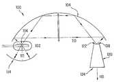
- FIG. 1is a schematic diagram of an illumination system according to one embodiment of the invention.
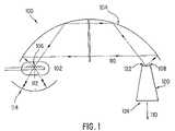
- FIG. 2is a schematic diagram of an illumination system according to an alternative embodiment of the invention.
- FIG. 3is a schematic diagram of an illumination system according to a third embodiment of the invention.
- FIG. 4is a schematic diagram of an illumination system according to a fourth embodiment of the invention.
- FIG. 5is a schematic diagram of an illumination system according to a fifth embodiment of the invention.
- FIG. 6is a schematic diagram of an illumination system according to a sixth embodiment of the invention.
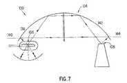
- FIG. 7is a schematic diagram of an illumination system according to a seventh embodiment of the invention.
- FIG. 8is a schematic diagram of an illumination system according to an eighth embodiment of the invention.
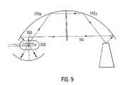
- FIG. 9is a schematic diagram of an illumination system according to a ninth embodiment of the invention.
- a filament lamp 102may be disposed proximate to a first focal point 106 of a reflector 104 having a first and second focal points 106 , 108 .
- Filament lamp 102may be, e.g. a tungsten filament lamp.
- Filament lamp 102emits rays of electromagnetic radiation 110 . Some of rays of electromagnetic radiation 110 are reflected by reflector 104 and converge substantially at second focal point 108 .
- Illumination system 100further includes an additional reflector 114 constructed and arranged to reflect at least part of the portion of electromagnetic radiation 112 that does not impinge directly on reflector 104 toward reflector 104 through first focal point 106 . Since a filament of filament lamp 102 already occupies first focal point 106 , however, the filament of filament lamp 102 substantially blocks electromagnetic radiation 112 . The filament of filament lamp 102 will thus absorb some of electromagnetic radiation 112 . The portion of electromagnetic radiation 112 that is absorbed by the filament of filament lamp 102 may heat the filament of filament lamp 102 , raising its temperature. A higher temperature results in an increased light output, which may be on the order of 30%.
- Additional reflector 114may be, e.g. a spherical retro-reflector disposed on a side of filament lamp 102 opposite reflector 104 to reflect electromagnetic radiation 112 emitted from filament lamp 102 toward reflector 104 through first focal point 106 .
- additional reflector 114may be a combination of a parabolic reflector 154 and a planar mirror 156 .
- a full circular parabolic reflectorcould be used.
- reflector 104has a coating 116 that reflects substantially only a pre-specified portion 118 of a spectrum of electromagnetic radiation 110 .
- Pre-specified portion 118may be, e.g. visible light radiation, ultraviolet (UV) radiation, infrared (IR) radiation, a pre-specified band of wavelengths of radiation, or a specific color of radiation.
- illumination system 100includes a filter 148 placed substantially in a path of rays of electromagnetic radiation 110 .
- Filter 148has a coating 150 that reflects substantially only a pre-specified portion 152 of a spectrum of electromagnetic radiation 110 .
- coating 150transmits substantially only a pre-specified portion 152 of a spectrum of electromagnetic radiation 110 .
- pre-specified portion 152may be, e.g. visible light radiation, ultraviolet radiation, infrared radiation, a pre-specified band of wavelengths of radiation, or a specific color of radiation.
- filter 148reflects ultraviolet radiation and infrared radiation back to first focal point 106 , while transmitting visible radiation toward second focal point 108 . This would be the case if, e.g. visible light was to be launched into an output device, but not ultraviolet radiation or infrared radiation.
- the infrared and ultraviolet radiation reflected by filter 148can thus be refocused onto the filament of filament lamp 102 , heating the filament further to produce more light.
- more of the infrared and ultraviolet radiationwould be trapped inside the reflector 104 and used for heating the filament of the filament lamp 102 , thus increasing the efficiency of the system 100 .
- the ultraviolet radiation and infrared radiation which would otherwise be wastedwould thus be re-used.
- one half of filter 148could be a reflector and the other half a filter coated with a coating such as, e.g. coating 150 .
- illumination system 100includes an output light pipe 120 having an input surface 122 and an output surface 124 .
- Input surface 122may be located proximate to second focal point 108 to collect substantially all of radiation 110 .
- Radiation 110passes through output light pipe 120 and may be transmitted substantially by output surface 124 .
- Output light pipe 120may be composed of, e.g. a material such as quartz, glass, plastic, or acrylic.
- Output light pipe 120may be, e.g. a homogenizer, a tapered light pipe, or a straight light pipe.
- Output light pipe 120may have, e.g. a cross-section such as a rectangle, a circle, a triangle, a trapezoid, a rhombus, a pentagon, a hexagon, or an octagon.
- illumination system 100may include further a fiber optic 126 , which may be illuminated substantially by radiation 110 transmitted at output surface 124 of output light pipe 120 , after which fiber optic 126 releases collected radiation 110 to provide for illumination at a desired location 128 .
- illumination system 100may include further a condenser lens 130 disposed substantially proximate to output surface 124 of output light pipe 120 .
- An image projection system 132 disposed substantially proximate to an output side 134 of condenser lens 130releases radiation 110 collected and condensed by condenser lens 130 to display an image 136 .
- illumination system 100includes a waveguide 146 disposed substantially proximate to output surface 124 .
- Waveguide 146may be, e.g. a single core optic fiber, a fiber bundle, a fused fiber bundle, a polygonal rod, or a hollow reflective light pipe.
- Waveguide 146may further be, e.g. a circular waveguide, a polygonal waveguide, a tapered waveguide, or a combination thereof.
- Waveguide 146may be composed of, e.g. a material such as quartz, glass, plastic, or acrylic.
- reflector 104 of illumination system 100comprises a first reflector 138 having a first optical axis 140 and a second reflector 142 having a second optical axis 144 .
- Second reflector 142may be placed substantially symmetrically to first reflector 138 such that first and second optical axes 140 , 144 are substantially collinear.
- first focal point 106may be a focal point of first reflector 138 and second focal point 108 may be a focal point of second reflector 142 .
- first and second reflectors 138 , 142may each be, e.g. at least a portion of a substantially toric surface of revolution. In another embodiment, first and second reflectors 138 , 142 may each be, e.g. at least a portion of a substantially spheroid surface of revolution.
- first reflector 138 shown in FIG. 7comprises at least a portion of a substantially ellipsoid surface of revolution, while second reflector 142 comprises at least a portion of a substantially hyperboloid surface of revolution.
- first reflector 138comprises at least a portion of a substantially hyperboloid surface of revolution, while second reflector 142 comprises at least a portion of a substantially ellipsoid surface of revolution.
- first and second reflectors 138 e, 142 emay each be, e.g. at least a portion of a substantially ellipsoid surface of revolution.
- FIG. 8shows an embodiment of illumination system 100 e using two semi-circular elliptical mirrors 138 e and 142 e with substantially co-linear optical axes 140 e , 144 e.
- the filament of filament lamp 102may be placed at the focus 106 e of elliptical reflector 138 e .
- a spherical reflector 114 eprovides retro-reflection.
- a spherical filter 148 emay be placed such that a center of curvature 158 of filter 148 e coincides with a common focal point 160 of the two elliptical reflectors 138 e , 142 e . Infrared and ultraviolet radiation incident onto the filter 148 e will be reflected back into itself along the same path back into the filament of filament lamp 102 .
- elliptical reflectors 138 e , 142 ehave substantially the same shape. In other embodiments, elliptical reflectors 138 e , 142 e might, e.g. have a different ellipticity such that the projected image may be close to 1:1.
- input surface 122 of output light pipe 120may be placed at second focus 108 e of second elliptical reflector 142 e for collecting and transforming a numerical aperture (NA) of electromagnetic radiation 110 into, e.g. a lower NA.
- NAnumerical aperture
- first and second reflectors 138 p , 142 pmay each be, e.g. at least a portion of a substantially paraboloid surface of revolution. Rays of radiation 110 collected by parabolic reflector 138 p may be collimated into parabolic reflector 142 p .
- the parabolic reflector 142 pmay be placed substantially symmetrically opposite parabolic reflector 138 p , thus producing an image of the filament of filament lamp 102 at first focal point 106 of parabolic reflector 138 p with a substantially unit magnification for all angles of light and preserving the brightness of the filament.
- a method of illuminationcomprises the steps of positioning a filament lamp 102 at a first focal point 106 of a reflector 104 , producing rays of radiation 110 by filament lamp 102 , reflecting a portion of rays of radiation 110 by reflector 104 toward a second focal point 108 of reflector 104 , converging rays of radiation 110 at second focal point 108 of second reflector 104 , reflecting at least part of a portion of rays of radiation 110 that do not impinge directly on reflector 104 toward reflector 104 through first focal point 106 of reflector 104 , positioning an output light pipe 120 having an input surface 122 and output surface 124 so input surface 122 may be substantially proximate to second focal point 108 , collecting rays of radiation at input surface 122 , passing rays of radiation 110 through output light pipe 120 , and outputting rays of radiation 110 from output surface 124 of output light pipe 120 .
Landscapes
- Physics & Mathematics (AREA)
- General Physics & Mathematics (AREA)
- Optics & Photonics (AREA)
- Engineering & Computer Science (AREA)
- General Engineering & Computer Science (AREA)
- Multimedia (AREA)
- Signal Processing (AREA)
- Non-Portable Lighting Devices Or Systems Thereof (AREA)
- Optical Elements Other Than Lenses (AREA)
Abstract
Description
Claims (11)
Priority Applications (1)
| Application Number | Priority Date | Filing Date | Title |
|---|---|---|---|
| US11/386,328US7618158B2 (en) | 2001-02-21 | 2006-03-22 | Illumination system using filament lamps |
Applications Claiming Priority (4)
| Application Number | Priority Date | Filing Date | Title |
|---|---|---|---|
| US26988801P | 2001-02-21 | 2001-02-21 | |
| US10/078,256US6955452B2 (en) | 2001-02-21 | 2002-02-20 | Illumination system using filament lamps |
| US11/208,142US20060034086A1 (en) | 2001-02-21 | 2005-08-19 | Illumination system using filament lamps |
| US11/386,328US7618158B2 (en) | 2001-02-21 | 2006-03-22 | Illumination system using filament lamps |
Related Parent Applications (1)
| Application Number | Title | Priority Date | Filing Date |
|---|---|---|---|
| US11/208,142ContinuationUS20060034086A1 (en) | 2001-02-21 | 2005-08-19 | Illumination system using filament lamps |
Publications (2)
| Publication Number | Publication Date |
|---|---|
| US20060227557A1 US20060227557A1 (en) | 2006-10-12 |
| US7618158B2true US7618158B2 (en) | 2009-11-17 |
Family
ID=23029057
Family Applications (3)
| Application Number | Title | Priority Date | Filing Date |
|---|---|---|---|
| US10/078,256Expired - Fee RelatedUS6955452B2 (en) | 2001-02-21 | 2002-02-20 | Illumination system using filament lamps |
| US11/208,142AbandonedUS20060034086A1 (en) | 2001-02-21 | 2005-08-19 | Illumination system using filament lamps |
| US11/386,328Expired - Fee RelatedUS7618158B2 (en) | 2001-02-21 | 2006-03-22 | Illumination system using filament lamps |
Family Applications Before (2)
| Application Number | Title | Priority Date | Filing Date |
|---|---|---|---|
| US10/078,256Expired - Fee RelatedUS6955452B2 (en) | 2001-02-21 | 2002-02-20 | Illumination system using filament lamps |
| US11/208,142AbandonedUS20060034086A1 (en) | 2001-02-21 | 2005-08-19 | Illumination system using filament lamps |
Country Status (9)
| Country | Link |
|---|---|
| US (3) | US6955452B2 (en) |
| EP (1) | EP1368681A4 (en) |
| JP (1) | JP2004526285A (en) |
| KR (1) | KR100638227B1 (en) |
| CN (1) | CN1219225C (en) |
| CA (1) | CA2437059A1 (en) |
| MX (1) | MXPA03007497A (en) |
| TW (1) | TW568990B (en) |
| WO (1) | WO2002075382A1 (en) |
Cited By (5)
| Publication number | Priority date | Publication date | Assignee | Title |
|---|---|---|---|---|
| CN103403596A (en)* | 2011-02-23 | 2013-11-20 | 欧司朗股份有限公司 | Lighting apparatus |
| US8789957B2 (en) | 2011-02-11 | 2014-07-29 | Coretronic Corporation | Light source module and projection apparatus |
| US20140218938A1 (en)* | 2011-10-14 | 2014-08-07 | 3M Innovative Properties Company | Lens assembly for remote phosphor led device |
| US20160231518A1 (en)* | 2013-10-14 | 2016-08-11 | Molex, Llc | Optical coupling and assembly |
| US20180080627A1 (en)* | 2011-10-20 | 2018-03-22 | Appotronics Corporation Limited | Light sources system and projection device using the same |
Families Citing this family (17)
| Publication number | Priority date | Publication date | Assignee | Title |
|---|---|---|---|---|
| US6565235B2 (en)* | 2000-10-26 | 2003-05-20 | Cogent Light Technologies Inc. | Folding an arc into itself to increase the brightness of an arc lamp |
| KR100638227B1 (en)* | 2001-02-21 | 2006-10-25 | 웨이비엔, 인코포레이티드 | Lighting system using filament lamp |
| CN100403161C (en)* | 2001-04-25 | 2008-07-16 | 威维恩有限公司 | Light recycling system for projection display and polarized light recycling method using the same |
| JP4972883B2 (en)* | 2005-06-17 | 2012-07-11 | 株式会社日立製作所 | Optical unit and projection-type image display device |
| JP4987866B2 (en)* | 2005-06-30 | 2012-07-25 | ウェイヴィーン・インコーポレイテッド | Dual paraboloidal reflector and dual ellipsoidal reflector system with optimized magnification |
| EP2297513A1 (en)* | 2008-05-30 | 2011-03-23 | Koninklijke Philips Electronics N.V. | Illumination device comprising a collimator |
| JP5381348B2 (en)* | 2009-06-02 | 2014-01-08 | セイコーエプソン株式会社 | Light source device, lighting system, projector |
| KR101009491B1 (en)* | 2010-04-28 | 2011-01-19 | 주식회사 토치 | Chair with adjustable backrest tilting distance |
| KR101009488B1 (en)* | 2010-04-28 | 2011-01-20 | 주식회사 토치 | Chairs with tiltable back |
| US9115867B2 (en)* | 2010-10-19 | 2015-08-25 | Macdonald, Dettwiler And Associates Inc. | Dual reflector system for linear lamp illuminators |
| CN103270437B (en)* | 2010-12-23 | 2020-08-07 | 哈曼专业丹麦公司 | Optical light mixer providing a homogeneous and uniform light beam |
| DE102011004563B4 (en)* | 2011-02-23 | 2014-02-20 | Osram Gmbh | Optical element and lighting device |
| CN102279456B (en)* | 2011-06-29 | 2013-09-11 | 中海阳新能源电力股份有限公司 | Light gathering power transmission one body type integration relay system |
| US9593825B2 (en)* | 2013-10-29 | 2017-03-14 | Microscan Systems, Inc. | Illumination system |
| KR101710534B1 (en)* | 2014-11-20 | 2017-02-28 | 박정익 | Optical system for sensors with optical method and sensors including the same optical system |
| US11187838B2 (en)* | 2017-07-31 | 2021-11-30 | Kla Corporation | Spectral filter for high-power fiber illumination sources |
| US11057963B2 (en)* | 2017-10-06 | 2021-07-06 | Applied Materials, Inc. | Lamp infrared radiation profile control by lamp filament design and positioning |
Citations (38)
| Publication number | Priority date | Publication date | Assignee | Title |
|---|---|---|---|---|
| US1913517A (en)* | 1929-04-24 | 1933-06-13 | Harold E Smith | Light projection |
| US2001528A (en)* | 1931-09-18 | 1935-05-14 | Gen Electric | Gaseous electric discharge device |
| US2496374A (en)* | 1943-11-24 | 1950-02-07 | Boucher And Keiser Company | Tubular electric lamp |
| US3247416A (en)* | 1963-04-16 | 1966-04-19 | Yamashita Isao | Headlight for cars |
| US3644730A (en)* | 1967-08-29 | 1972-02-22 | Libbey Owens Ford Glass Co | Selective reflectors |
| US3772506A (en) | 1971-07-07 | 1973-11-13 | Original Hanau Quarzlampen | Operating lamp provided with a light pipe |
| US3986767A (en) | 1974-04-12 | 1976-10-19 | United Technologies Corporation | Optical focus device |
| US4020336A (en)* | 1974-10-24 | 1977-04-26 | Robert Bosch G.M.B.H. | Vehicular fog headlight |
| US4149227A (en) | 1977-06-20 | 1979-04-10 | Corning Glass Works | Reflector |
| US4357075A (en) | 1979-07-02 | 1982-11-02 | Hunter Thomas M | Confocal reflector system |
| US4473295A (en) | 1981-08-31 | 1984-09-25 | Laser Precision Corporation | Parabolic focusing apparatus for optical spectroscopy |
| US4519266A (en) | 1981-09-30 | 1985-05-28 | Wabco Fahrzeugbremsen Gmbh | Gear selector unit for a transmission |
| US4608622A (en) | 1983-12-28 | 1986-08-26 | Dentsply Research & Development Corp. | Multi-function light source |
| US4634276A (en) | 1983-06-15 | 1987-01-06 | U.S. Philips Corporation | Slit imaging system using two concave mirrors |
| US4757431A (en) | 1986-07-01 | 1988-07-12 | Laser Media | Off-axis application of concave spherical reflectors as condensing and collecting optics |
| USRE32912E (en) | 1981-08-10 | 1989-04-25 | Laser Precision Corporation | Parabolic focusing apparatus for optical spectroscopy |
| US4897771A (en) | 1987-11-24 | 1990-01-30 | Lumitex, Inc. | Reflector and light system |
| US4956759A (en) | 1988-12-30 | 1990-09-11 | North American Philips Corporation | Illumination system for non-imaging reflective collector |
| US4957759A (en) | 1986-09-08 | 1990-09-18 | North Carolina State University | Method for the ultrapasteurization of liquid whole egg products |
| EP0401351A1 (en) | 1988-12-05 | 1990-12-12 | Microcontrole | Optical measurement device and method. |
| JPH0678906A (en) | 1992-03-17 | 1994-03-22 | Philips Electron Nv | Image device and x-ray inspection device containing it |
| US5414600A (en) | 1993-07-30 | 1995-05-09 | Cogent Light Technologies, Inc. | Condensing and collecting optical system using an ellipsoidal reflector |
| US5430634A (en) | 1992-08-03 | 1995-07-04 | Cogent Light Technologies, Inc. | Concentrating and collecting optical system using concave toroidal reflectors |
| US5707131A (en) | 1996-01-24 | 1998-01-13 | Cogent Light Technologies, Inc. | Collections and condensing optical system using cascaded concave reflectors |
| US5777809A (en) | 1995-07-28 | 1998-07-07 | Koito Manufacturing Co., Ltd. | Reflection mirror for a vehicle lamp and a method of forming the same |
| US5803579A (en) | 1996-06-13 | 1998-09-08 | Gentex Corporation | Illuminator assembly incorporating light emitting diodes |
| US5873646A (en) | 1996-06-14 | 1999-02-23 | Aktiebolaget Electrolux | Lighting arrangement at a refrigerator or freezer cabinet |
| US5900973A (en) | 1995-06-21 | 1999-05-04 | Thomson Multimedia S.A. | Optical polarization device and projection system of liquid crystal valve type utilizing such a device |
| US5986792A (en) | 1998-02-03 | 1999-11-16 | Farlight Corporation | Lighting system sequencer and method |
| JP2000067623A (en) | 1998-08-17 | 2000-03-03 | Ushio Inc | Lighting device using optical fiber |
| WO2000022344A1 (en) | 1998-10-13 | 2000-04-20 | Cogent Light Technologies, Inc. | Concentrating and collecting optical system using concave toroidal reflectors |
| WO2001002774A1 (en) | 1999-07-01 | 2001-01-11 | Cogent Light Technologies, Inc. | Condensing and collecting optical system using parabolic reflectors or a corresponding ellipsoid/hyperboloid pair of reflectors |
| US6227682B1 (en) | 2000-03-22 | 2001-05-08 | Cogent Light Technologies, Inc. | Coupling of light from a small light source for projection systems using parabolic reflectors |
| WO2001073487A2 (en) | 2000-03-27 | 2001-10-04 | Cogent Light Technologies, Inc. | Coupling of light from a light source to a target using dual ellipsoidal reflectors |
| US6356700B1 (en) | 1998-06-08 | 2002-03-12 | Karlheinz Strobl | Efficient light engine systems, components and methods of manufacture |
| US6616304B2 (en) | 2000-10-04 | 2003-09-09 | Cogent Light Technologies, Inc. | Temperature control for arc lamps |
| US6619820B2 (en) | 2000-09-20 | 2003-09-16 | Cogent Light Technologies, Inc. | Light condensing and collecting systems using lensed light pipes |
| US6955452B2 (en)* | 2001-02-21 | 2005-10-18 | Wavien, Inc. | Illumination system using filament lamps |
Family Cites Families (2)
| Publication number | Priority date | Publication date | Assignee | Title |
|---|---|---|---|---|
| US1562502A (en)* | 1924-03-18 | 1925-11-24 | American Flatlite Company | Light projector |
| GB8629989D0 (en)* | 1986-12-16 | 1987-01-28 | Pa Management Consultants | Fibre optic coupling |
- 2002
- 2002-02-19KRKR1020037011005Apatent/KR100638227B1/ennot_activeExpired - Fee Related
- 2002-02-19EPEP02733802Apatent/EP1368681A4/ennot_activeCeased
- 2002-02-19JPJP2002573934Apatent/JP2004526285A/enactivePending
- 2002-02-19WOPCT/US2002/004687patent/WO2002075382A1/enactiveApplication Filing
- 2002-02-19CACA002437059Apatent/CA2437059A1/ennot_activeAbandoned
- 2002-02-19CNCNB028051068Apatent/CN1219225C/ennot_activeExpired - Fee Related
- 2002-02-19MXMXPA03007497Apatent/MXPA03007497A/enunknown
- 2002-02-20USUS10/078,256patent/US6955452B2/ennot_activeExpired - Fee Related
- 2002-02-21TWTW091103023Apatent/TW568990B/ennot_activeIP Right Cessation
- 2005
- 2005-08-19USUS11/208,142patent/US20060034086A1/ennot_activeAbandoned
- 2006
- 2006-03-22USUS11/386,328patent/US7618158B2/ennot_activeExpired - Fee Related
Patent Citations (40)
| Publication number | Priority date | Publication date | Assignee | Title |
|---|---|---|---|---|
| US1913517A (en)* | 1929-04-24 | 1933-06-13 | Harold E Smith | Light projection |
| US2001528A (en)* | 1931-09-18 | 1935-05-14 | Gen Electric | Gaseous electric discharge device |
| US2496374A (en)* | 1943-11-24 | 1950-02-07 | Boucher And Keiser Company | Tubular electric lamp |
| US3247416A (en)* | 1963-04-16 | 1966-04-19 | Yamashita Isao | Headlight for cars |
| US3644730A (en)* | 1967-08-29 | 1972-02-22 | Libbey Owens Ford Glass Co | Selective reflectors |
| US3772506A (en) | 1971-07-07 | 1973-11-13 | Original Hanau Quarzlampen | Operating lamp provided with a light pipe |
| US3986767A (en) | 1974-04-12 | 1976-10-19 | United Technologies Corporation | Optical focus device |
| US4020336A (en)* | 1974-10-24 | 1977-04-26 | Robert Bosch G.M.B.H. | Vehicular fog headlight |
| US4149227A (en) | 1977-06-20 | 1979-04-10 | Corning Glass Works | Reflector |
| US4357075A (en) | 1979-07-02 | 1982-11-02 | Hunter Thomas M | Confocal reflector system |
| USRE32912E (en) | 1981-08-10 | 1989-04-25 | Laser Precision Corporation | Parabolic focusing apparatus for optical spectroscopy |
| US4473295A (en) | 1981-08-31 | 1984-09-25 | Laser Precision Corporation | Parabolic focusing apparatus for optical spectroscopy |
| US4519266A (en) | 1981-09-30 | 1985-05-28 | Wabco Fahrzeugbremsen Gmbh | Gear selector unit for a transmission |
| US4634276A (en) | 1983-06-15 | 1987-01-06 | U.S. Philips Corporation | Slit imaging system using two concave mirrors |
| US4608622A (en) | 1983-12-28 | 1986-08-26 | Dentsply Research & Development Corp. | Multi-function light source |
| US4757431A (en) | 1986-07-01 | 1988-07-12 | Laser Media | Off-axis application of concave spherical reflectors as condensing and collecting optics |
| US4957759B1 (en) | 1986-09-08 | 2000-02-29 | Univ North Carolina State | Method for the ultrapasteurization of liquid whole egg products |
| US4957759A (en) | 1986-09-08 | 1990-09-18 | North Carolina State University | Method for the ultrapasteurization of liquid whole egg products |
| US4897771A (en) | 1987-11-24 | 1990-01-30 | Lumitex, Inc. | Reflector and light system |
| EP0401351A1 (en) | 1988-12-05 | 1990-12-12 | Microcontrole | Optical measurement device and method. |
| US5191393A (en) | 1988-12-05 | 1993-03-02 | Micro-Controle | Optical measurement device and method |
| US4956759A (en) | 1988-12-30 | 1990-09-11 | North American Philips Corporation | Illumination system for non-imaging reflective collector |
| JPH0678906A (en) | 1992-03-17 | 1994-03-22 | Philips Electron Nv | Image device and x-ray inspection device containing it |
| US5430634A (en) | 1992-08-03 | 1995-07-04 | Cogent Light Technologies, Inc. | Concentrating and collecting optical system using concave toroidal reflectors |
| US5414600A (en) | 1993-07-30 | 1995-05-09 | Cogent Light Technologies, Inc. | Condensing and collecting optical system using an ellipsoidal reflector |
| US5900973A (en) | 1995-06-21 | 1999-05-04 | Thomson Multimedia S.A. | Optical polarization device and projection system of liquid crystal valve type utilizing such a device |
| US5777809A (en) | 1995-07-28 | 1998-07-07 | Koito Manufacturing Co., Ltd. | Reflection mirror for a vehicle lamp and a method of forming the same |
| US5707131A (en) | 1996-01-24 | 1998-01-13 | Cogent Light Technologies, Inc. | Collections and condensing optical system using cascaded concave reflectors |
| US5803579A (en) | 1996-06-13 | 1998-09-08 | Gentex Corporation | Illuminator assembly incorporating light emitting diodes |
| US5873646A (en) | 1996-06-14 | 1999-02-23 | Aktiebolaget Electrolux | Lighting arrangement at a refrigerator or freezer cabinet |
| US5986792A (en) | 1998-02-03 | 1999-11-16 | Farlight Corporation | Lighting system sequencer and method |
| US6356700B1 (en) | 1998-06-08 | 2002-03-12 | Karlheinz Strobl | Efficient light engine systems, components and methods of manufacture |
| JP2000067623A (en) | 1998-08-17 | 2000-03-03 | Ushio Inc | Lighting device using optical fiber |
| WO2000022344A1 (en) | 1998-10-13 | 2000-04-20 | Cogent Light Technologies, Inc. | Concentrating and collecting optical system using concave toroidal reflectors |
| WO2001002774A1 (en) | 1999-07-01 | 2001-01-11 | Cogent Light Technologies, Inc. | Condensing and collecting optical system using parabolic reflectors or a corresponding ellipsoid/hyperboloid pair of reflectors |
| US6227682B1 (en) | 2000-03-22 | 2001-05-08 | Cogent Light Technologies, Inc. | Coupling of light from a small light source for projection systems using parabolic reflectors |
| WO2001073487A2 (en) | 2000-03-27 | 2001-10-04 | Cogent Light Technologies, Inc. | Coupling of light from a light source to a target using dual ellipsoidal reflectors |
| US6619820B2 (en) | 2000-09-20 | 2003-09-16 | Cogent Light Technologies, Inc. | Light condensing and collecting systems using lensed light pipes |
| US6616304B2 (en) | 2000-10-04 | 2003-09-09 | Cogent Light Technologies, Inc. | Temperature control for arc lamps |
| US6955452B2 (en)* | 2001-02-21 | 2005-10-18 | Wavien, Inc. | Illumination system using filament lamps |
Cited By (8)
| Publication number | Priority date | Publication date | Assignee | Title |
|---|---|---|---|---|
| US8789957B2 (en) | 2011-02-11 | 2014-07-29 | Coretronic Corporation | Light source module and projection apparatus |
| CN103403596A (en)* | 2011-02-23 | 2013-11-20 | 欧司朗股份有限公司 | Lighting apparatus |
| US20130329426A1 (en)* | 2011-02-23 | 2013-12-12 | Klaus Finsterbusch | Lighting apparatus |
| US9581313B2 (en)* | 2011-02-23 | 2017-02-28 | Osram Gmbh | Lighting apparatus |
| US20140218938A1 (en)* | 2011-10-14 | 2014-08-07 | 3M Innovative Properties Company | Lens assembly for remote phosphor led device |
| US9625123B2 (en)* | 2011-10-14 | 2017-04-18 | 3M Innovative Properties Company | Lens assembly for remote phosphor LED device |
| US20180080627A1 (en)* | 2011-10-20 | 2018-03-22 | Appotronics Corporation Limited | Light sources system and projection device using the same |
| US20160231518A1 (en)* | 2013-10-14 | 2016-08-11 | Molex, Llc | Optical coupling and assembly |
Also Published As
| Publication number | Publication date |
|---|---|
| EP1368681A4 (en) | 2005-08-03 |
| KR100638227B1 (en) | 2006-10-25 |
| US6955452B2 (en) | 2005-10-18 |
| EP1368681A1 (en) | 2003-12-10 |
| US20060034086A1 (en) | 2006-02-16 |
| MXPA03007497A (en) | 2003-12-08 |
| CN1491366A (en) | 2004-04-21 |
| TW568990B (en) | 2004-01-01 |
| WO2002075382A1 (en) | 2002-09-26 |
| US20020141191A1 (en) | 2002-10-03 |
| JP2004526285A (en) | 2004-08-26 |
| CA2437059A1 (en) | 2002-09-26 |
| CN1219225C (en) | 2005-09-14 |
| KR20030096260A (en) | 2003-12-24 |
| US20060227557A1 (en) | 2006-10-12 |
Similar Documents
| Publication | Publication Date | Title |
|---|---|---|
| US7618158B2 (en) | Illumination system using filament lamps | |
| CA2402560C (en) | Coupling of light from a light source to a target using dual ellipsoidal reflectors | |
| US20020122621A1 (en) | Coupling of light from a non-circular light source | |
| US6619820B2 (en) | Light condensing and collecting systems using lensed light pipes | |
| CN101189472B (en) | Double-paraboloid and double-ellipsoid reflecting system with optimized magnification | |
| US7513630B2 (en) | Compact dual ellipsoidal reflector (DER) system having two molded ellipsoidal modules such that a radiation receiving module reflects a portion of rays to an opening in the other module | |
| JP3847927B2 (en) | Arc tube and light source device using the same | |
| US6565235B2 (en) | Folding an arc into itself to increase the brightness of an arc lamp | |
| US7213947B2 (en) | Multiple output illumination using reflectors | |
| US6318885B1 (en) | Method and apparatus for coupling light and producing magnified images using an asymmetrical ellipsoid reflective surface | |
| EP1914573A2 (en) | Coupling of light from a light source to a target using dual ellipsoidal reflectors |
Legal Events
| Date | Code | Title | Description |
|---|---|---|---|
| STCF | Information on status: patent grant | Free format text:PATENTED CASE | |
| AS | Assignment | Owner name:CLT ASSOCIATES, L.P., NEW JERSEY Free format text:SECURITY AGREEMENT W/SCHEDULE A;ASSIGNOR:WAVIEN, INC.;REEL/FRAME:023498/0886 Effective date:20031231 Owner name:CLT ASSOCIATES, L.P.,NEW JERSEY Free format text:SECURITY AGREEMENT W/SCHEDULE A;ASSIGNOR:WAVIEN, INC.;REEL/FRAME:023498/0886 Effective date:20031231 | |
| FPAY | Fee payment | Year of fee payment:4 | |
| AS | Assignment | Owner name:CLT ASSOCIATES, L.P., NEW JERSEY Free format text:INTELLECTUAL PROPERTY SECURITY AGREEMENT;ASSIGNOR:WAVIEN, INC.;REEL/FRAME:037159/0048 Effective date:20151123 | |
| AS | Assignment | Owner name:MEADOWSTAR ENTERPRISES, LTD., NEW YORK Free format text:ASSIGNMENT OF ASSIGNORS INTEREST;ASSIGNOR:WAVIEN, INC.;REEL/FRAME:037361/0364 Effective date:20151217 | |
| AS | Assignment | Owner name:MEADOWSTAR ENTERPRISES, LTD., NEW YORK Free format text:SECURITY AGREEMENT;ASSIGNOR:WAVIEN, INC.;REEL/FRAME:037396/0475 Effective date:20151217 Owner name:WAVIEN, INC., CALIFORNIA Free format text:RELEASE BY SECURED PARTY;ASSIGNOR:CLT ASSOCIATES, L.P.;REEL/FRAME:037397/0175 Effective date:20151217 | |
| FPAY | Fee payment | Year of fee payment:8 | |
| FEPP | Fee payment procedure | Free format text:MAINTENANCE FEE REMINDER MAILED (ORIGINAL EVENT CODE: REM.); ENTITY STATUS OF PATENT OWNER: SMALL ENTITY | |
| LAPS | Lapse for failure to pay maintenance fees | Free format text:PATENT EXPIRED FOR FAILURE TO PAY MAINTENANCE FEES (ORIGINAL EVENT CODE: EXP.); ENTITY STATUS OF PATENT OWNER: SMALL ENTITY | |
| STCH | Information on status: patent discontinuation | Free format text:PATENT EXPIRED DUE TO NONPAYMENT OF MAINTENANCE FEES UNDER 37 CFR 1.362 | |
| FP | Lapsed due to failure to pay maintenance fee | Effective date:20211117 |