US7617932B2 - Medical device package, kit and associated methods - Google Patents
Medical device package, kit and associated methodsDownload PDFInfo
- Publication number
- US7617932B2 US7617932B2US10/666,154US66615403AUS7617932B2US 7617932 B2US7617932 B2US 7617932B2US 66615403 AUS66615403 AUS 66615403AUS 7617932 B2US7617932 B2US 7617932B2
- Authority
- US
- United States
- Prior art keywords
- medical device
- cap member
- cavity
- device package
- connector
- Prior art date
- Legal status (The legal status is an assumption and is not a legal conclusion. Google has not performed a legal analysis and makes no representation as to the accuracy of the status listed.)
- Expired - Fee Related, expires
Links
Images


Classifications
- A—HUMAN NECESSITIES
- A61—MEDICAL OR VETERINARY SCIENCE; HYGIENE
- A61B—DIAGNOSIS; SURGERY; IDENTIFICATION
- A61B5/00—Measuring for diagnostic purposes; Identification of persons
- A61B5/145—Measuring characteristics of blood in vivo, e.g. gas concentration or pH-value ; Measuring characteristics of body fluids or tissues, e.g. interstitial fluid or cerebral tissue
- A61B5/1468—Measuring characteristics of blood in vivo, e.g. gas concentration or pH-value ; Measuring characteristics of body fluids or tissues, e.g. interstitial fluid or cerebral tissue using chemical or electrochemical methods, e.g. by polarographic means
- A61B5/1486—Measuring characteristics of blood in vivo, e.g. gas concentration or pH-value ; Measuring characteristics of body fluids or tissues, e.g. interstitial fluid or cerebral tissue using chemical or electrochemical methods, e.g. by polarographic means using enzyme electrodes, e.g. with immobilised oxidase
- A—HUMAN NECESSITIES
- A61—MEDICAL OR VETERINARY SCIENCE; HYGIENE
- A61B—DIAGNOSIS; SURGERY; IDENTIFICATION
- A61B5/00—Measuring for diagnostic purposes; Identification of persons
- A—HUMAN NECESSITIES
- A61—MEDICAL OR VETERINARY SCIENCE; HYGIENE
- A61B—DIAGNOSIS; SURGERY; IDENTIFICATION
- A61B5/00—Measuring for diagnostic purposes; Identification of persons
- A61B5/15—Devices for taking samples of blood
- A61B5/150007—Details
- A61B5/150015—Source of blood
- A61B5/150022—Source of blood for capillary blood or interstitial fluid
- A—HUMAN NECESSITIES
- A61—MEDICAL OR VETERINARY SCIENCE; HYGIENE
- A61B—DIAGNOSIS; SURGERY; IDENTIFICATION
- A61B5/00—Measuring for diagnostic purposes; Identification of persons
- A61B5/15—Devices for taking samples of blood
- A61B5/150007—Details
- A61B5/150206—Construction or design features not otherwise provided for; manufacturing or production; packages; sterilisation of piercing element, piercing device or sampling device
- A61B5/150305—Packages specially adapted for piercing devices or blood sampling devices
- A—HUMAN NECESSITIES
- A61—MEDICAL OR VETERINARY SCIENCE; HYGIENE
- A61B—DIAGNOSIS; SURGERY; IDENTIFICATION
- A61B5/00—Measuring for diagnostic purposes; Identification of persons
- A61B5/15—Devices for taking samples of blood
- A61B5/150007—Details
- A61B5/150358—Strips for collecting blood, e.g. absorbent
- A—HUMAN NECESSITIES
- A61—MEDICAL OR VETERINARY SCIENCE; HYGIENE
- A61B—DIAGNOSIS; SURGERY; IDENTIFICATION
- A61B5/00—Measuring for diagnostic purposes; Identification of persons
- A61B5/15—Devices for taking samples of blood
- A61B5/150007—Details
- A61B5/150374—Details of piercing elements or protective means for preventing accidental injuries by such piercing elements
- A61B5/150381—Design of piercing elements
- A61B5/150412—Pointed piercing elements, e.g. needles, lancets for piercing the skin
- A61B5/150427—Specific tip design, e.g. for improved penetration characteristics
- A—HUMAN NECESSITIES
- A61—MEDICAL OR VETERINARY SCIENCE; HYGIENE
- A61B—DIAGNOSIS; SURGERY; IDENTIFICATION
- A61B5/00—Measuring for diagnostic purposes; Identification of persons
- A61B5/15—Devices for taking samples of blood
- A61B5/150007—Details
- A61B5/150374—Details of piercing elements or protective means for preventing accidental injuries by such piercing elements
- A61B5/150534—Design of protective means for piercing elements for preventing accidental needle sticks, e.g. shields, caps, protectors, axially extensible sleeves, pivotable protective sleeves
- A61B5/150572—Pierceable protectors, e.g. shields, caps, sleeves or films, e.g. for hygienic purposes
- A—HUMAN NECESSITIES
- A61—MEDICAL OR VETERINARY SCIENCE; HYGIENE
- A61B—DIAGNOSIS; SURGERY; IDENTIFICATION
- A61B5/00—Measuring for diagnostic purposes; Identification of persons
- A61B5/15—Devices for taking samples of blood
- A61B5/150007—Details
- A61B5/150374—Details of piercing elements or protective means for preventing accidental injuries by such piercing elements
- A61B5/150534—Design of protective means for piercing elements for preventing accidental needle sticks, e.g. shields, caps, protectors, axially extensible sleeves, pivotable protective sleeves
- A61B5/150694—Procedure for removing protection means at the time of piercing
- A61B5/150717—Procedure for removing protection means at the time of piercing manually removed
- A—HUMAN NECESSITIES
- A61—MEDICAL OR VETERINARY SCIENCE; HYGIENE
- A61B—DIAGNOSIS; SURGERY; IDENTIFICATION
- A61B5/00—Measuring for diagnostic purposes; Identification of persons
- A61B5/15—Devices for taking samples of blood
- A61B5/150007—Details
- A61B5/150801—Means for facilitating use, e.g. by people with impaired vision; means for indicating when used correctly or incorrectly; means for alarming
- A61B5/150824—Means for facilitating use, e.g. by people with impaired vision; means for indicating when used correctly or incorrectly; means for alarming by visual feedback
- A—HUMAN NECESSITIES
- A61—MEDICAL OR VETERINARY SCIENCE; HYGIENE
- A61B—DIAGNOSIS; SURGERY; IDENTIFICATION
- A61B5/00—Measuring for diagnostic purposes; Identification of persons
- A61B5/15—Devices for taking samples of blood
- A61B5/150007—Details
- A61B5/150885—Preventing re-use
- A61B5/150923—Preventing re-use by means for destroying components or parts, e.g. by cutting or piercing
- A—HUMAN NECESSITIES
- A61—MEDICAL OR VETERINARY SCIENCE; HYGIENE
- A61B—DIAGNOSIS; SURGERY; IDENTIFICATION
- A61B5/00—Measuring for diagnostic purposes; Identification of persons
- A61B5/15—Devices for taking samples of blood
- A61B5/151—Devices specially adapted for taking samples of capillary blood, e.g. by lancets, needles or blades
- A61B5/15142—Devices intended for single use, i.e. disposable
- A—HUMAN NECESSITIES
- A61—MEDICAL OR VETERINARY SCIENCE; HYGIENE
- A61B—DIAGNOSIS; SURGERY; IDENTIFICATION
- A61B5/00—Measuring for diagnostic purposes; Identification of persons
- A61B5/15—Devices for taking samples of blood
- A61B5/157—Devices characterised by integrated means for measuring characteristics of blood
- A—HUMAN NECESSITIES
- A61—MEDICAL OR VETERINARY SCIENCE; HYGIENE
- A61B—DIAGNOSIS; SURGERY; IDENTIFICATION
- A61B50/00—Containers, covers, furniture or holders specially adapted for surgical or diagnostic appliances or instruments, e.g. sterile covers
- A61B50/30—Containers specially adapted for packaging, protecting, dispensing, collecting or disposing of surgical or diagnostic appliances or instruments
- A61B50/3001—Containers specially adapted for packaging, protecting, dispensing, collecting or disposing of surgical or diagnostic appliances or instruments for sharps
- A—HUMAN NECESSITIES
- A61—MEDICAL OR VETERINARY SCIENCE; HYGIENE
- A61B—DIAGNOSIS; SURGERY; IDENTIFICATION
- A61B17/00—Surgical instruments, devices or methods
- A61B17/32—Surgical cutting instruments
- A61B17/3209—Incision instruments
- A61B17/3211—Surgical scalpels, knives; Accessories therefor
- A61B17/3215—Packages or dispensers for scalpel blades
- A—HUMAN NECESSITIES
- A61—MEDICAL OR VETERINARY SCIENCE; HYGIENE
- A61B—DIAGNOSIS; SURGERY; IDENTIFICATION
- A61B50/00—Containers, covers, furniture or holders specially adapted for surgical or diagnostic appliances or instruments, e.g. sterile covers
- A61B50/30—Containers specially adapted for packaging, protecting, dispensing, collecting or disposing of surgical or diagnostic appliances or instruments
- A61B50/36—Containers specially adapted for packaging, protecting, dispensing, collecting or disposing of surgical or diagnostic appliances or instruments for collecting or disposing of used articles
- A61B50/362—Containers specially adapted for packaging, protecting, dispensing, collecting or disposing of surgical or diagnostic appliances or instruments for collecting or disposing of used articles for sharps
Definitions
- the present inventionrelates, in general, to medical device packages and, in particular, to medical device packages for receiving, and securely and removably retaining, a medical device.
- a variety of medical devicesrequire packaging to, for example, protect the medical device from damage prior to use and to maintain sterility of the medical device.
- a dermal tissue penetration membere.g., a lancet or micro-needle
- the associated packageshould provide for an uncomplicated deployment of the dermal tissue penetration member during use, while also providing for protection of a user from inadvertent contact with the dermal tissue penetration member prior and subsequent to use.
- the packagingshould provide humidity resistance for the test strip during storage.
- Single-use (i.e., disposable) integrated medical devicesare illustrative of the above requirements in that they require a medical device package that maintains sterility and protects the single-use integrated medical device contained therein from damage prior to use.
- Such medical device packagesshould also provide humidity resistance and UV protection for a test strip of such single-use integrated medical devices prior to use.
- the medical device packageshould provide for deployment of a dermal tissue penetration member of such a single-use integrated medical device during use, as well as for disabling (i.e., preventing subsequent use) and safely discarding the single-use integrated medical device following use.
- Medical device packages according to the present inventionprovide a sterility barrier and/or protection for a medical device (e.g., an integrated medical device) enclosed therein. Embodiments of medical device packages according to the present invention also provide for an uncomplicated deployment of the medical device during use. Furthermore, with respect to integrated medical devices that include a dermal tissue penetration member (e.g., a lancet or micro-needle), medical device packages according to embodiments of the present invention protect the dermal tissue penetration member from damage, humidity, and/or contamination prior to use, and protect a user from accidental contact therewith. Embodiments of the medical device packages according to the present invention are also adapted to disable the medical device following use, thereby preventing its repeated use. In addition, due to relative simplicity of configuration, medical device packages according to the present invention are cost effective.
- a dermal tissue penetration membere.g., a lancet or micro-needle
- a medical device packageincludes a main cap member and a minor cap member.
- the main cap memberhas a proximal end, a distal end and a cavity with a cavity opening at the proximal end.
- the cavityis configured to receive, and to securely and removably retain, a medical device (e.g., an integrated medical device that includes a dermal tissue penetration member and a test strip) at least partially therein.
- the minor cap memberis configured to seal the cavity opening once the medical device has been received in the cavity.
- Medical device package kitsinclude a main cap member, a minor cap member and a connector.
- the main cap memberhas a proximal end, a distal end and a cavity.
- the cavityhas a cavity opening at the proximal end of the main cap member.
- the cavityis configured to receive, and to securely and removably retain, a medical device at least partially therein.
- the minor cap memberis configured to seal the cavity opening once the medical device has been received in the cavity.
- the connectoris configured to engage the medical device during removal of the medical device from the cavity.
- Methods according to the present inventionenable the uncomplicated deployment (i.e., extraction) of a medical device from a medical device package.
- Methods for extracting a medical device from a medical device package according to embodiments of the present inventionfirst include providing a medical device package, with a medical device (e.g., an integrated medical device) therein, and a connector.
- the provided medical device packageincludes a main cap member having a cavity and proximal and distal ends, and a minor cap member.
- the cavity of the main cap memberhas a cavity opening at the proximal end of the main cap member and is configured to receive, and to securely and removably retain, the medical device at least partially therein.
- the minor cap memberis configured to seal the cavity opening.
- the methodsalso include breaching the minor cap member with the connector such that at least a portion of the connector enters the cavity.
- the medical deviceis engaged by the connector and extracted from the medical device package.
- Other methods according to the present inventioninclude disabling a medical device that has been extracted from a medical device package by inserting the medical device back into a cavity of the medical device package to a position that results in a disabling of repeated use of the medical device.
- Such disablementcan be obtained by, for example, a wedging of the medical device into a fixed position within the cavity of the medical device package.
- FIG. 1is a simplified exploded perspective view of a medical device package according to the present invention
- FIGS. 2A-2Dare simplified top, side, proximal end and perspective proximal end views of the main cap member of the medical device package of FIG. 1 ;
- FIG. 3Ais a simplified cross-sectional side view of the main cap member of the medical device package of FIGS. 1A through 2D , representing a view along line 3 A- 3 A of FIG. 2A in the direction of the arrows;
- FIG. 3Bis a simplified cross-sectional top view of the main cap member of the medical device package of FIGS. 1A through 2D , representing a view along line 3 B- 3 B of FIG. 2C in the direction of the arrows;
- FIGS. 4A and 4Bare simplified perspective and side views, respectively of a medical device that can be contained within exemplary embodiments of medical device packages according to the present invention
- FIG. 5Ais a simplified proximal-end view of the main cap member of FIG. 1 containing the medical device of FIGS. 4A and 4B ;
- FIG. 5Bis a simplified cross-sectional view of the main cap member and medical device of FIG. 5A , representing a view along line 5 B- 5 B of FIG. 5A in the direction of the arrows;
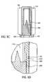
- FIG. 5Cis a cross-sectional, top view of the main cap member and medical device of FIG. 5A , representing a view along line 5 C- 5 C of FIG. 5A in the direction of the arrows;
- FIG. 5Dis an enlargement of a portion of the cross-sectional, top view of the main cap member and medical device of FIG. 5C ;
- FIGS. 6A and 6Bare simplified top and perspective views of an exemplary embodiment of a connector for use with exemplary embodiments of medical device packages according to the present invention
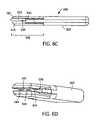
- FIG. 6Cis a side view of an exemplary embodiment of a connector, representing a view along line 6 C- 6 C in FIG. 6A in the direction of the arrows;
- FIG. 6Dis a perspective view of the proximal end of an exemplary embodiment of a connector that is used with the preferred embodiment of the medical device package according to the present invention.
- FIG. 7is a top view of a connector and a proximal end view of an exemplary embodiment of a medical device package according to the present invention.
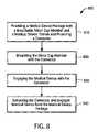
- FIG. 8is a flow chart illustrating a sequence of steps in a process for extracting a medical device from a medical device package according to an exemplary embodiment of the present invention
- FIGS. 9A-Dare schematic, cross-sectional views depicting various stages of the process of FIG. 8 ;
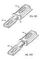
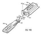
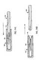
- FIGS. 10A-Eare schematic, perspective views depicting various stages of the process of FIG. 8 ;
- FIGS. 11A-Care schematic, top cross-sectional views depicting various stages of the process of FIG. 8 ;
- FIGS. 12A-Care schematic enlargements of portions of FIGS. 11A-C , respectively;
- FIG. 13is a flow chart illustrating a sequence of steps in a process for extracting a medical device from a medical device package and subsequently disabling the medical device according to an exemplary embodiment of the present invention
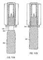
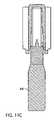
- FIGS. 14A-Dare schematic, cross-sectional views depicting various stages of the process of FIG. 13 ;
- FIGS. 15A-Dare schematic, perspective views depicting various stages of the process of FIG. 13 ;
- FIGS. 16A and 16Bare schematic, top cross-sectional depictions of a stage in the process of FIG. 13 ;
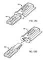
- FIG. 17is a simplified perspective view of a medical device package according to another exemplary embodiment of the present invention containing a medical device;
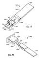
- FIG. 18is an exploded perspective view of yet another exemplary embodiment of a medical device package containing an integrated medical device according to the present invention.
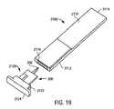
- FIG. 19is an exploded perspective view of yet another exemplary embodiment of a medical device package containing an integrated medical device according to the present invention.
- FIG. 20is a simplified cross-sectional top view of an additional exemplary embodiment of a medical device package according to the present invention.
- FIG. 21is a simplified cross-sectional top view of the medical device package of FIG. 20 with a medical device retained therein;
- FIG. 22is a simplified cross-sectional top view of the medical device package of FIG. 21 with a medical device disabled therein.
- FIGS. 1 , 2 A- 2 D, 3 A and 3 Bare various simplified views of a medical device package 100 according to an exemplary embodiment of the present invention.
- Medical device package 100includes a main cap member 110 and a minor cap member 150 .
- Main cap member 110includes a cavity 116 therein, a proximal end 112 and a distal end 114 .
- Cavity 116has a cavity opening 118 at the proximal end 112 of the main cap member 110 and is configured to receive, and to securely and removably retain, a medical device (e.g., integrated medical device 300 , illustrated in FIGS. 4A and 4B ), at least partially therein.
- a medical devicee.g., integrated medical device 300 , illustrated in FIGS. 4A and 4B
- FIGS. 4A and 4Bare simplified perspective and side views, respectively, of an exemplary integrated medical device 300 that can be securely and removably contained within medical device package 100 .
- Integrated medical device 300includes a test strip 304 and a dermal tissue penetration member 302 , as illustrated in FIGS. 4A-4B .
- Test strip 304has a reaction area (not shown) and electrical contacts 306 that terminate on a distal end 310 of medical device 300 .
- Electrical contacts 306are made of any suitable conductive material, such as carbon.
- Dermal tissue penetration member 302includes a lancet 320 adapted to pierce a user's skin and draw blood into the reaction area of test strip 304 .
- cavity opening 118is bounded by a rim 120 of sufficient surface area to enable minor cap member 150 to be adhered to rim 120 by processes known to those skilled in the art, including, but not limited to, heat sealing processes.
- minor cap member 150 and main cap member 110 of medical device package 100provide a sterility barrier and humidity protection for a medical device contained therein.
- main cap member 110External features of main cap member 110 include a first peripheral edge 122 , a second peripheral edge 124 , a main cap upper surface 126 and a main cap lower surface 128 . As shown in FIG. 2A , first peripheral edge 122 and second peripheral edge 124 are truncated to end at the distal edge 121 of rim 120 . If desired, the first and second peripheral edges 122 , 124 can be asymmetrically disposed about a longitudinal axis of the main cap member. Such an asymmetric configuration can serve to properly orient the medical device package during its insertion into a receiving slot of associated hardware (for example, an analytical meter receiving slot configured to direct the medical device package to a connector described below with respect to FIGS. 6A-6D ).
- a receiving slot of associated hardwarefor example, an analytical meter receiving slot configured to direct the medical device package to a connector described below with respect to FIGS. 6A-6D .
- main cap upper surface 126optionally includes a directional marker 130 that is discontinuous with (e.g., raised above or, alternatively, recessed below) the remainder of main cap upper surface 126 .
- Directional marker 130may include, but is not limited to, an ellipse 132 and an arrow 134 , as depicted in FIGS. 1 and 2A .
- Directional marker 130provides a user with both tactile and visual cues for proper orientation of medical device package 100 during use.
- Cavity 116is defined (at least in part) by a first smooth inner surface 127 and a second smooth inner surface 129 and includes first and second lateral channels 140 and 142 , respectively, as shown in FIGS. 2C-2D and 3 B.
- cavity 116is also defined by first lateral surface 170 located internally to first peripheral edge 122 and a second lateral surface 172 located internally to second peripheral edge 124 .
- first lateral surface 170has a first sloped land 160
- second lateral surface 172has a second sloped land 162 .
- First sloped land 160terminates at the beginning of first lateral channel 140
- second sloped land 162terminates at the beginning of second lateral channel 142 .
- First lateral channel 140 and second lateral channel 142extend about half way along first and second laterals surfaces 170 and 172 , respectively.
- First and second sloped lands 160 , 162begin at cavity opening 118 , and slope inwardly and distally towards distal end 114 of main cap member 110 .
- First and second lateral channels 140 and 142begin at the end of first and second sloped lands 160 and 162 , respectively, and extend approximately half way into cavity 116 .
- First and second lateral channels 140 and 142are divided into a post-use portion 202 , a transition point 204 , and a pre-use portion 206 (see FIGS. 3A and 3B ).
- first lateral channel 140is the mirror image of second lateral channel 142 .
- first and second sloped lands 160 , 162 , first and second lateral channels 140 , 142 , transition point 204 , and pre-use portion 206are configured to receive, and securely and removably retain, a medical device within cavity 116 .
- post-use portion 202is configured to disable a used medical device (as explained in detail below with respect to, for example, FIGS. 16A and 16B ).
- Main cap member 110can be formed of any suitable material known to those of skill in the art including, for example, rigid plastic materials such as polystyrene, polycarbonate and polyester. Such rigid plastic materials are impervious to puncturing and to air and/or air-borne bacteria and, therefore, provide a sterility barrier and a puncture-resistant protective barrier. It can be particularly beneficial in terms of humidity protection for main cap member 110 to be formed of a desiccant-loaded high-density polyethylene (e.g., 2AP desiccant-loaded high-density polyethylene, commercially available from Airsec in France).
- a desiccant-loaded high-density polyethylenee.g., 2AP desiccant-loaded high-density polyethylene, commercially available from Airsec in France.
- Minor cap member 150is configured to seal cavity opening 118 once a medical device has been received in cavity 116 .
- minor cap member 150is a breachable film such as breachable metallic foil.
- suitable materials for minor cap member 150include paper, polymer and Tyvek.
- minor cap member 150can take a variety of forms, all of which are capable of sealing the cavity opening of an associated main cap member once a medical device has been at least partially received within the cavity of the main cap member.
- FIG. 2Dis a proximal end perspective view of main cap member 110 .
- Transition point 204includes a vertical shoulder 204 A and a horizontal shoulder 204 B, as shown in FIG. 2D .
- vertical shoulder 204 Aprevents the medical device (not shown) from being inserting past transition point 204 (see FIGS. 2A and 2B ).
- the unused medical deviceis inserted only to a first position, which is defined by contact of the unused medical device with transition point 204 .
- a used medical devicecan be inserted back into cavity 116 of main cap member 110 for disablement and disposal purposes.
- the used medical devicee.g., integrated medical device 300 of FIGS. 4A and 4B subsequent to use
- the used medical deviceis inserted beyond the first position to a second position, wherein the used medical device extends past transition point 204 toward distal end 114 and is irreparably damaged (i.e., disabled) by horizontal shoulder 204 B.
- Such damageprevents a subsequent removal, and thus repeated use, of the once used medical device.
- FIGS. 5A-5Dare various views of main cap member 100 of FIG. 1 with integrated medical device 300 of FIGS. 4A and 4B inserted therein prior to use of integrated medical device 300 (i.e., integrated medical device 300 is “unused”).
- integrated medical device 300extends between first lateral channel 140 and second lateral channel 142 and lies parallel to first smooth inner surface 127 and second smooth inner surface 129 .
- Unused integrated medical device 300is securely retained within cavity 116 via a friction fit with first lateral channel 140 and second lateral channel 142 .
- Distal end 310 of integrated medical device 300remains within proximal end 112 of medical device package 100 and is not in contact with first lateral channel 140 and second lateral channel 142 .
- lancet 320is within cavity 116 and thus protected from inadvertent damage.
- Unused integrated medical device 300is positioned within first and second lateral channels 140 and 142 such that proximal end 312 of integrated medical device 300 touches, but goes no further than, transition point 204 , and distal end 310 of integrated medical device 300 remains free from contact with first and second lateral channels 140 and 142 in cavity 116 (see FIGS. 5C and 5D ) of main cap member 110 .
- FIGS. 6A through 6Ddepict an exemplary embodiment of a connector 500 adapted to extract integrated medical device 300 from medical device package 100 .
- connector 500can advantageously be used to mechanically and/or manually manipulate such a medical device once the medical device has been extracted from the medical device package.
- connector 500can be used to transfer a medical device from a medical device package to a metering system.
- connector 500may be a component (either a removable component or a permanently integrated component) of a metering system (e.g., an analytical meter configured to determine analyte concentrations in biological fluid samples).
- a metering systeme.g., an analytical meter configured to determine analyte concentrations in biological fluid samples.
- connector 500can be combined with medical device packages to form a kit according to an exemplary embodiment of the present invention.
- Connector 500includes a strip extracting member 502 and a connector body 504 .
- connector 500includes a proximal end 510 , a distal end 512 , an upper surface 514 and a lower surface 516 .
- Connector body 504includes a connector directional marker 518 on upper surface 514 .
- Connector directional marker 518(optional) is discontinuous with (e.g., raised above or recessed below) upper surface 514 of connector 500 .
- Connector directional marker 518may include, but is not limited to, an ellipse 530 and an arrow 532 .
- Connector directional marker 518provides a user with both tactile and visual cues for proper orientation of connector 500 when inserted into medical device package 100 .
- Strip extracting member 502includes a lower strip engaging arm 540 , an upper strip engaging arm 542 and a plurality of strip engaging elements 544 , as illustrated in FIGS. 6C-6D .
- Connector 500also includes electrical leads (not shown) for providing an electrical connection(s) between strip engaging elements 544 and an analytical meter.
- strip extracting member 502includes a vertical barrier 550 that contacts distal end 310 of integrated medical device 300 when integrated medical device 300 is engaged by connector 500 . Although three strip engaging elements 544 are depicted in FIG. 6D for the purpose of illustration and explanation, strip extracting member 502 can include any suitable number of strip-engaging elements. Strip engaging elements 544 are located on inner surface 543 of upper strip engaging arm 542 .
- Strip engaging elements 544are spring-loaded connections formed, for example, by being molded into connector 500 by any suitable process known to those skilled in the art. Strip engaging elements 544 are used to contact test strip 304 of integrated medical device 300 through electrical contacts 306 . One skilled in the art will recognize that connector 500 can provide electrical communication between test strip 304 and an analytical meter via strip engaging elements 544 and the connector's electrical leads.
- FIG. 7is a top view of connector 500 and a proximal end view of main cap member 110 , with dashed vertical lines showing proper alignment of connector 500 during extraction of a medical device.
- Solids horizontal line 5 F- 5 Findicates width of the medical device (for example, approximately 5.5 mm), while solid horizontal line 5 G- 5 G indicates the width of strip extracting element 502 (for example, approximately 4.5 mm).
- FIG. 8is a flow chart illustrating a sequence of steps in a process 800 for extracting a medical device from a medical device package according to an exemplary embodiment of the present invention.
- Process 800is described below utilizing FIGS. 9A-D (schematic, cross-sectional views depicting various stages of process 800 ), FIGS. 10A-E (schematic, perspective views depicting various stages of process 800 ), FIGS. 11A-C (schematic, top cross-sectional views of various stages of process 800 ) and FIGS. 12A-C (schematic enlargements of portions of FIGS. 11A-C , respectively).
- Process 800includes first providing (i) a medical device package with a minor cap member and a medical device contained therein and (ii) a connector, as set forth in step 810 of FIG. 8 .
- the provided medical device package and connectorcan be any suitable medical device package according to the present invention that includes a breachable minor cap member (e.g., the medical device package of FIG. 1 ) and any suitable connector according to the present invention.
- the provision of an exemplary medical device package and connectorare depicted in FIG. 9A and FIG. 10A , wherein like elements of the medical device package and connector of earlier figures are identified with like numerals.
- step 820the minor cap member is breached (e.g., ruptured) with the connector such that at least a portion of the connector has entered into the cavity of the main cap member (see FIGS. 9B , 10 B, 11 A and 12 A).
- the medical deviceis engaged by the connector (see FIGS. 9C , 10 C, 11 B and 12 B), as set forth in step 830 .
- the force required for the connector to engage with the medical deviceis, for example, approximately 2N.
- the connector and engaged medical deviceare then extracted from the cavity of the medical device package, as set forth in step 840 (see FIGS. 9D , 10 D- 10 E, 11 C and 12 C).
- Each of the steps of process 800can be performed, for example, either manually by a user or with the aid of a mechanical and/or electrical device.
- strip engaging elements of the connectorengage a test strip 304 of integrated medical device 300 and a vertical barrier of the connector contacts the distal end of the integrated medical device 300 .
- the force required for the breaching the minor cap member and engagement of the medical devicecan be, for example, in the range of about 1.5 N to 2.5 N.
- Solid line 5 F- 5 F of FIG. 10Erepresents a dimension that is identical to the dimension of solid horizontal line 5 F- 5 F of FIG. 7 (i.e., the width of integrated medical device 300 ).
- Solid line 10 H- 10 H in FIG. 10Erepresents the width of the medical device's lancet.
- Solid line 101 - 101 of FIG. 10Erepresents the width of cavity opening of medical device package, which is larger than the dimension represented by solid line 5 F- 5 F to assure a medical device's smooth insertion into, and removal from the cavity.
- Process 800can be performed manually or automatically. Furthermore, process 800 can be, for example, performed by an integrated device that combines an analytical meter and a connector in a configuration that provides for (i) a medical device to be extracted from a medical device package; (ii) a sample (e.g., a whole blood sample) to be obtained from a user and (iii) an analytical result (e.g., blood glucose concentration of the whole blood sample) to determined, all by a single operation of the integrated device.
- Mechanical motionsmay be incorporated into a lancet cocking action, new test strip deployment and/or ejection.
- FIG. 13is a flow chart illustrating a sequence of steps in a process 1300 for extracting a medical device from a medical device package for use and subsequently disabling the medical device after use according to an exemplary embodiment of the present invention.
- Process 1300is described below utilizing FIGS. 14A-14D (schematic, cross-sectional views depicting various stages of process 1300 ), FIGS. 15A-15D (schematic, perspective views depicting various stages of process 1300 ) and FIGS. 16A-16B (schematic, top cross-sectional views of a stage of process 1300 ).
- Process 1300includes first providing (i) a medical device package with a minor cap member and a medical device contained therein at a first position and (ii) a connector, as set forth in step 1310 of FIG. 13 .
- a medical device package with a minor cap member and a medical device contained therein at a first positionand a connector, as set forth in step 1310 of FIG. 13 .
- the provided medical device package and connectorcan be any medical device package according to the present invention that includes a breachable minor cap member (e.g., the medical device package of FIG. 1 ).
- the minor cap memberis breached (e.g., ruptured) with the connector such that at least a portion of the connector has entered the cavity of the main cap member.
- the medical deviceis then engaged by the connector, as set forth in step 1330 .
- the connector and engaged medical deviceare then extracted from the cavity of the medical device package for use, as set forth in step 1340 .
- step 1350the connector and engaged medical device are inserted back into a cavity of the medical device package to a second position, whereby the medical device is disabled from reuse (see FIGS. 14A-14C , 15 A- 15 C and 16 A- 16 B).
- the connectoris then disengaged from the medical device and withdrawn from the medical device package, as set forth in step 1360 .
- the medical deviceis disabled by virtue of the medical device being wedged into the cavity such that the force required to remove the medical device from the cavity is greater than the force required to disengage the connector from the medical device. Therefore, an attempt to re-extract the medical device with the connector would be unsuccessful since the connector would become disengaged from the medical device before sufficient force could be applied to extract the wedged medical device.
- the medical deviceis inserted to a second position within post-use portion 202 that is beyond transition points 204 of the first and second lateral channels (see, in particular, FIG. 16B ), i.e., beyond the first position.
- the force required to insert the medical device into the medical device package and disable the medical deviceis, for example, approximately 7N.
- disablement of the medical deviceis a result of the medical device being wedged into the cavity such that it cannot be re-extracted using the connector.
- FIG. 17depicts a medical device package 1900 according to another exemplary embodiment of the present invention.
- dashed linesindicate certain features that are hidden due to the perspective nature of FIG. 17 .
- FIG. 17depicts the circumstance where a medical device (i.e., integrated medical device 300 of FIGS. 4A and 4B ) is retained partially within medical device package 1900 .
- electrical contacts 306project from the cavity opening and minor cap member. Since electrical contacts 306 project from both the cavity opening and the minor cap member, engagement of the electrical contacts with a connector can be simplified. For example, there is no need to breach or otherwise remove any component of the medical device package to obtain access to the electrical contacts and the electrical contacts are free to deflect upon engagement with a connector.
- Medical device package 1900includes a main cap member 1910 with a proximal end 1912 , a distal end 1914 , a cavity 1918 and a cavity opening 1916 .
- Distal end 1914is configured to function as a handle during manually removal of medical device package 1900 from secondary packaging (not illustrated).
- Medical device package 1900can be constructed, for example, of molded plastic or other material that is impervious to air and/or air-borne bacteria, to provide a sterile-protective and puncture-resistant barrier.
- Suitable materialsinclude, but are not limited to, polystyrene, polyethylene, polycarbonate and polyester.
- Cavity 1918 of medical device package 1900is defined by surfaces depicted with dashed lines in FIG. 17 .
- Cavity opening 1916is configured to provide for the placement of dermal tissue penetration member 302 of medical device 300 wholly within cavity 1918 , as shown in FIG. 17 .
- Medical device package 1900includes internally disposed ribs 1960 , located distally to cavity opening 1916 . Ribs 1960 serve to seal cavity 1918 once a medical device has been inserted partially therein, and provide a sterile and protective barrier for dermal tissue penetration member 302 by creating a tortuous path between the external environment and the cavity of the medical device package. Ribs 1960 , together with an at least partially inserted medical device, serve as a minor cap member for medical device package 1900 .
- elastomeric o-ringscould be employed to seal cavity 1918 once a medical device has been inserted partially therein, and to provide a sterile and protective barrier for dermal tissue penetration member 302 .
- FIG. 18is an exploded perspective view of a medical device package 2000 according to yet another exemplary embodiment of the present invention containing a medical device 300 (as depicted in FIGS. 4A and 4B ).
- Medical device package 2000includes a main cap member 2010 and a minor cap member 2020 .
- Main cap member 2010has a proximal end 2012 , a distal end 2014 , a cavity opening (not shown), and a cavity (also not shown).
- the cavity and cavity opening of main cap member 2010are configured for placement of a dermal tissue penetration member of an integrated medical device wholly therein, thus providing a protective barrier for such a dermal tissue penetration member.
- Minor cap member 2020has a proximal end 2022 , a distal end 2024 , a minor cap opening 2026 , and a minor cap cavity (not shown in FIG. 18 ). Minor cap opening 2026 and the minor cap cavity are configured for the placement of a test strip 304 of an integrated medical device wholly or partially therein. Furthermore, proximal end 2012 of main cap member 2010 is adapted to fit wholly within minor cap opening 2026 and the minor cap cavity. Once main cap member 2010 is fit within minor cap opening 2026 and the minor cap cavity, integrated medical device 300 is completely enclosed and provided with a sterile-protective and moisture-free barrier.
- Both main cap member 2010 and minor cap member 2020are beneficially constructed of molded plastic or other rigid material that is impervious to air and/or air-borne bacteria, to provide a sterile-protective and puncture-resistant barrier.
- Suitable materials for main cap member 2010 and minor cap member 2020include, but are not limited to, polystyrene, polyethylene, polycarbonate and polyester.
- FIG. 19is an exploded perspective view of a medical device package 2100 according to yet another exemplary embodiment of the present invention.
- Medical device package 2100includes a main cap member 2110 and a minor cap member 2120 .
- Main cap member 2110has a proximal end 2112 , a distal end 2114 , a cavity opening 2116 and a cavity (not shown).
- Cavity opening 2116 and the cavity of medical device package 2100are configured for placement of a dermal tissue penetration member 302 of an integrated medical device and a minor cap member proximal end 2122 (described below) wholly therein, thus providing a protective barrier for dermal tissue penetration member 302 .
- Minor cap member 2120 of medical device package 2100has a proximal end 2122 and a distal end 2124 .
- integrated medical device 300is permanently attached to minor cap member 2120 at proximal end 2122 .
- the permanent attachment of such an integrated medical device to minor cap member 2120is envisioned to provide handling benefits during use of the integrated medical device.
- minor cap member 2120could be gripped by a meter, with the main cap member then being easily removed by a user (e.g., by pulling, twisting or snapping) to deploy the integrated medical device.
- FIGS. 20 , 21 and 22depict the main cap member 2450 of a medical package device according to yet another exemplary embodiment of the present invention (for purposes of clarity, the minor cap member of this medical device package is not illustrated).
- FIG. 21depicts an integrated medical device 300 retained within main cap member 2450 and
- FIG. 22depicts an integrated medical device 300 disabled within main cap member 2450 .
- Main cap member 2450is identical to main cap member 110 of FIG. 3B , with the exception that main cap member 2450 has a distal end cavity 2452 configured for disablement and disposal of an integrated medical device.
- embodiments of medical device packages according to the present inventioncan be secondarily packaged for single use in, for example, a vial or cartridge configured for dispensing the medical device packages.
- the secondary packagemay be constructed of material containing desiccant or may contain separately packaged desiccant for maintaining contents moisture free.
- Such medical devicesinclude, but are not limited to, integrated medical devices that include a combination of a test strip and a lancet, examples of which are described in the aforementioned International Application No. PCT/GB01/05634 (published as WO 02/49507 on Jun. 27, 2002) and U.S. patent application Ser. No. 10/143,399, both of which are fully incorporated herein by reference.
- test stripsmay have, but are not limited to, an electrochemical or photometric configuration. For illustrative purposes only, medical devices in various figures of the present disclosure were depicted as having an electrochemical configuration.
- medical device packages according to embodiments of the present inventioncan be employed with medical device adapted for the measurement of, for example, glucose, ketones, glycated albumin, coagulation parameters and cholesterol of a sample.
- medical device packages according to the present inventionmay be contained within a combined sample collection and metering system designed for in-situ testing. Examples of such systems designed for in-situ testing are disclosed in International Patent Application No. PCT/US01/07169 (published as WO 01/64105 A1 on Sep. 7, 2001) and International Patent Application No. PCT/GB02/03772 (published as WO 03/015627 A1 on Feb. 27, 2003), each of which is fully incorporated herein by reference.
Landscapes
- Health & Medical Sciences (AREA)
- Life Sciences & Earth Sciences (AREA)
- Engineering & Computer Science (AREA)
- Surgery (AREA)
- Public Health (AREA)
- Veterinary Medicine (AREA)
- General Health & Medical Sciences (AREA)
- Biomedical Technology (AREA)
- Heart & Thoracic Surgery (AREA)
- Medical Informatics (AREA)
- Molecular Biology (AREA)
- Physics & Mathematics (AREA)
- Animal Behavior & Ethology (AREA)
- Biophysics (AREA)
- Pathology (AREA)
- Hematology (AREA)
- General Chemical & Material Sciences (AREA)
- Chemical & Material Sciences (AREA)
- Chemical Kinetics & Catalysis (AREA)
- Nuclear Medicine, Radiotherapy & Molecular Imaging (AREA)
- Optics & Photonics (AREA)
- Diabetes (AREA)
- Manufacturing & Machinery (AREA)
- Dermatology (AREA)
- Measurement Of The Respiration, Hearing Ability, Form, And Blood Characteristics Of Living Organisms (AREA)
- Infusion, Injection, And Reservoir Apparatuses (AREA)
- Packages (AREA)
- Surgical Instruments (AREA)
Abstract
Description
Claims (6)
Priority Applications (19)
| Application Number | Priority Date | Filing Date | Title |
|---|---|---|---|
| US10/666,154US7617932B2 (en) | 2003-09-19 | 2003-09-19 | Medical device package, kit and associated methods |
| SG200809420-3ASG149046A1 (en) | 2003-09-19 | 2004-09-17 | Medical device package, kit and associated methods |
| AU2004212582AAU2004212582B2 (en) | 2003-09-19 | 2004-09-17 | Medical device package, kit and associated methods |
| NO20043898ANO20043898L (en) | 2003-09-19 | 2004-09-17 | Packaging, equipment and associated medical device procedures |
| JP2004272042AJP5132870B2 (en) | 2003-09-19 | 2004-09-17 | Medical device package, kit, and related methods |
| TW093127811ATWI348366B (en) | 2003-09-19 | 2004-09-17 | Medical device package |
| SG200405116ASG110145A1 (en) | 2003-09-19 | 2004-09-17 | Medical device package, kit and associated methods |
| CA2481873ACA2481873C (en) | 2003-09-19 | 2004-09-17 | Medical device package, kit and associated methods |
| ES04255661.3TES2527856T3 (en) | 2003-09-19 | 2004-09-17 | Medical device container, kit and associated methods |
| EP04255661.3AEP1518509B1 (en) | 2003-09-19 | 2004-09-17 | Medical device package, kit and associated methods |
| CN200410090503ACN100584709C (en) | 2003-09-19 | 2004-09-18 | Medical device packaging, kit, and related methods |
| IL164128AIL164128A (en) | 2003-09-19 | 2004-09-19 | Medical device package and kit containing it |
| RU2004128092/14ARU2358683C2 (en) | 2003-09-19 | 2004-09-20 | Medical device package, complete set and related methods |
| KR1020040075120AKR101157810B1 (en) | 2003-09-19 | 2004-09-20 | Medical Device package, Kit and associated methods |
| MXPA04009128AMXPA04009128A (en) | 2003-09-19 | 2004-09-20 | Medical device package, kit and associated methods. |
| HK05107426.4AHK1074987B (en) | 2003-09-19 | 2005-08-24 | Medical device package, kit and associated methods |
| US11/388,450US20060231442A1 (en) | 2003-09-19 | 2006-03-24 | Medical device package |
| US11/388,548US20060196795A1 (en) | 2003-09-19 | 2006-03-24 | Medical device package kit |
| US11/388,451US20060200046A1 (en) | 2003-09-19 | 2006-03-24 | Method for extracting a medical device from a medical device package |
Applications Claiming Priority (1)
| Application Number | Priority Date | Filing Date | Title |
|---|---|---|---|
| US10/666,154US7617932B2 (en) | 2003-09-19 | 2003-09-19 | Medical device package, kit and associated methods |
Related Child Applications (3)
| Application Number | Title | Priority Date | Filing Date |
|---|---|---|---|
| US11/388,451Continuation-In-PartUS20060200046A1 (en) | 2003-09-19 | 2006-03-24 | Method for extracting a medical device from a medical device package |
| US11/388,450Continuation-In-PartUS20060231442A1 (en) | 2003-09-19 | 2006-03-24 | Medical device package |
| US11/388,548Continuation-In-PartUS20060196795A1 (en) | 2003-09-19 | 2006-03-24 | Medical device package kit |
Publications (2)
| Publication Number | Publication Date |
|---|---|
| US20050061700A1 US20050061700A1 (en) | 2005-03-24 |
| US7617932B2true US7617932B2 (en) | 2009-11-17 |
Family
ID=34194775
Family Applications (4)
| Application Number | Title | Priority Date | Filing Date |
|---|---|---|---|
| US10/666,154Expired - Fee RelatedUS7617932B2 (en) | 2003-09-19 | 2003-09-19 | Medical device package, kit and associated methods |
| US11/388,450AbandonedUS20060231442A1 (en) | 2003-09-19 | 2006-03-24 | Medical device package |
| US11/388,548AbandonedUS20060196795A1 (en) | 2003-09-19 | 2006-03-24 | Medical device package kit |
| US11/388,451AbandonedUS20060200046A1 (en) | 2003-09-19 | 2006-03-24 | Method for extracting a medical device from a medical device package |
Family Applications After (3)
| Application Number | Title | Priority Date | Filing Date |
|---|---|---|---|
| US11/388,450AbandonedUS20060231442A1 (en) | 2003-09-19 | 2006-03-24 | Medical device package |
| US11/388,548AbandonedUS20060196795A1 (en) | 2003-09-19 | 2006-03-24 | Medical device package kit |
| US11/388,451AbandonedUS20060200046A1 (en) | 2003-09-19 | 2006-03-24 | Method for extracting a medical device from a medical device package |
Country Status (14)
| Country | Link |
|---|---|
| US (4) | US7617932B2 (en) |
| EP (1) | EP1518509B1 (en) |
| JP (1) | JP5132870B2 (en) |
| KR (1) | KR101157810B1 (en) |
| CN (1) | CN100584709C (en) |
| AU (1) | AU2004212582B2 (en) |
| CA (1) | CA2481873C (en) |
| ES (1) | ES2527856T3 (en) |
| IL (1) | IL164128A (en) |
| MX (1) | MXPA04009128A (en) |
| NO (1) | NO20043898L (en) |
| RU (1) | RU2358683C2 (en) |
| SG (2) | SG149046A1 (en) |
| TW (1) | TWI348366B (en) |
Cited By (9)
| Publication number | Priority date | Publication date | Assignee | Title |
|---|---|---|---|---|
| US8641210B2 (en) | 2011-11-30 | 2014-02-04 | Izi Medical Products | Retro-reflective marker including colored mounting portion |
| US8661573B2 (en) | 2012-02-29 | 2014-03-04 | Izi Medical Products | Protective cover for medical device having adhesive mechanism |
| US20140116919A1 (en)* | 2012-11-01 | 2014-05-01 | K-Jump Health Co., Ltd. | Packaging box with test strips and gripper assembly thereof |
| USD773656S1 (en)* | 2015-01-30 | 2016-12-06 | Newgen Surgical, Inc. | Pencil electrode holder |
| US10898244B2 (en) | 2018-11-16 | 2021-01-26 | DePuy Synthes Products, Inc. | Packaging for trochanteric femoral nail telescoping head element |
| US11395711B2 (en) | 2019-06-05 | 2022-07-26 | Stryker European Operations Limited | Packaging systems and methods for mounting a tool on a surgical device using the same |
| US11690680B2 (en) | 2019-03-19 | 2023-07-04 | Mako Surgical Corp. | Trackable protective packaging for tools and methods for calibrating tool installation using the same |
| US11807729B2 (en) | 2021-04-14 | 2023-11-07 | Goex Corporation | Polyethylene terephthalate-polyethylene naphthalate copolymer extruded sheet suitable for medical device packaging |
| US12161489B2 (en) | 2017-04-12 | 2024-12-10 | Mako Surgical Corp. | Packaging systems and methods for mounting a tool on a surgical device |
Families Citing this family (90)
| Publication number | Priority date | Publication date | Assignee | Title |
|---|---|---|---|---|
| US6036924A (en) | 1997-12-04 | 2000-03-14 | Hewlett-Packard Company | Cassette of lancet cartridges for sampling blood |
| US6391005B1 (en) | 1998-03-30 | 2002-05-21 | Agilent Technologies, Inc. | Apparatus and method for penetration with shaft having a sensor for sensing penetration depth |
| DE10057832C1 (en) | 2000-11-21 | 2002-02-21 | Hartmann Paul Ag | Blood analysis device has syringe mounted in casing, annular mounting carrying needles mounted behind test strip and being swiveled so that needle can be pushed through strip and aperture in casing to take blood sample |
| US8641644B2 (en) | 2000-11-21 | 2014-02-04 | Sanofi-Aventis Deutschland Gmbh | Blood testing apparatus having a rotatable cartridge with multiple lancing elements and testing means |
| US7344507B2 (en) | 2002-04-19 | 2008-03-18 | Pelikan Technologies, Inc. | Method and apparatus for lancet actuation |
| US8337419B2 (en) | 2002-04-19 | 2012-12-25 | Sanofi-Aventis Deutschland Gmbh | Tissue penetration device |
| US7041068B2 (en) | 2001-06-12 | 2006-05-09 | Pelikan Technologies, Inc. | Sampling module device and method |
| EP1395185B1 (en) | 2001-06-12 | 2010-10-27 | Pelikan Technologies Inc. | Electric lancet actuator |
| JP4272051B2 (en) | 2001-06-12 | 2009-06-03 | ペリカン テクノロジーズ インコーポレイテッド | Blood sampling apparatus and method |
| US9795747B2 (en) | 2010-06-02 | 2017-10-24 | Sanofi-Aventis Deutschland Gmbh | Methods and apparatus for lancet actuation |
| JP4209767B2 (en) | 2001-06-12 | 2009-01-14 | ペリカン テクノロジーズ インコーポレイテッド | Self-optimized cutting instrument with adaptive means for temporary changes in skin properties |
| WO2002101359A2 (en) | 2001-06-12 | 2002-12-19 | Pelikan Technologies, Inc. | Integrated blood sampling analysis system with multi-use sampling module |
| US9427532B2 (en) | 2001-06-12 | 2016-08-30 | Sanofi-Aventis Deutschland Gmbh | Tissue penetration device |
| US9226699B2 (en) | 2002-04-19 | 2016-01-05 | Sanofi-Aventis Deutschland Gmbh | Body fluid sampling module with a continuous compression tissue interface surface |
| AU2002344825A1 (en) | 2001-06-12 | 2002-12-23 | Pelikan Technologies, Inc. | Method and apparatus for improving success rate of blood yield from a fingerstick |
| US7981056B2 (en) | 2002-04-19 | 2011-07-19 | Pelikan Technologies, Inc. | Methods and apparatus for lancet actuation |
| US7749174B2 (en) | 2001-06-12 | 2010-07-06 | Pelikan Technologies, Inc. | Method and apparatus for lancet launching device intergrated onto a blood-sampling cartridge |
| US7344894B2 (en) | 2001-10-16 | 2008-03-18 | Agilent Technologies, Inc. | Thermal regulation of fluidic samples within a diagnostic cartridge |
| US7331931B2 (en) | 2002-04-19 | 2008-02-19 | Pelikan Technologies, Inc. | Method and apparatus for penetrating tissue |
| US7901362B2 (en) | 2002-04-19 | 2011-03-08 | Pelikan Technologies, Inc. | Method and apparatus for penetrating tissue |
| US7481776B2 (en) | 2002-04-19 | 2009-01-27 | Pelikan Technologies, Inc. | Method and apparatus for penetrating tissue |
| US8267870B2 (en) | 2002-04-19 | 2012-09-18 | Sanofi-Aventis Deutschland Gmbh | Method and apparatus for body fluid sampling with hybrid actuation |
| US7582099B2 (en) | 2002-04-19 | 2009-09-01 | Pelikan Technologies, Inc | Method and apparatus for penetrating tissue |
| US7976476B2 (en) | 2002-04-19 | 2011-07-12 | Pelikan Technologies, Inc. | Device and method for variable speed lancet |
| US7371247B2 (en) | 2002-04-19 | 2008-05-13 | Pelikan Technologies, Inc | Method and apparatus for penetrating tissue |
| US7141058B2 (en) | 2002-04-19 | 2006-11-28 | Pelikan Technologies, Inc. | Method and apparatus for a body fluid sampling device using illumination |
| US8784335B2 (en) | 2002-04-19 | 2014-07-22 | Sanofi-Aventis Deutschland Gmbh | Body fluid sampling device with a capacitive sensor |
| US7524293B2 (en) | 2002-04-19 | 2009-04-28 | Pelikan Technologies, Inc. | Method and apparatus for penetrating tissue |
| US7563232B2 (en) | 2002-04-19 | 2009-07-21 | Pelikan Technologies, Inc. | Method and apparatus for penetrating tissue |
| US9248267B2 (en) | 2002-04-19 | 2016-02-02 | Sanofi-Aventis Deustchland Gmbh | Tissue penetration device |
| US7648468B2 (en) | 2002-04-19 | 2010-01-19 | Pelikon Technologies, Inc. | Method and apparatus for penetrating tissue |
| US8579831B2 (en) | 2002-04-19 | 2013-11-12 | Sanofi-Aventis Deutschland Gmbh | Method and apparatus for penetrating tissue |
| US7232451B2 (en) | 2002-04-19 | 2007-06-19 | Pelikan Technologies, Inc. | Method and apparatus for penetrating tissue |
| US7674232B2 (en) | 2002-04-19 | 2010-03-09 | Pelikan Technologies, Inc. | Method and apparatus for penetrating tissue |
| US7892183B2 (en) | 2002-04-19 | 2011-02-22 | Pelikan Technologies, Inc. | Method and apparatus for body fluid sampling and analyte sensing |
| US7297122B2 (en) | 2002-04-19 | 2007-11-20 | Pelikan Technologies, Inc. | Method and apparatus for penetrating tissue |
| US7717863B2 (en) | 2002-04-19 | 2010-05-18 | Pelikan Technologies, Inc. | Method and apparatus for penetrating tissue |
| US9314194B2 (en) | 2002-04-19 | 2016-04-19 | Sanofi-Aventis Deutschland Gmbh | Tissue penetration device |
| US8221334B2 (en) | 2002-04-19 | 2012-07-17 | Sanofi-Aventis Deutschland Gmbh | Method and apparatus for penetrating tissue |
| US7229458B2 (en) | 2002-04-19 | 2007-06-12 | Pelikan Technologies, Inc. | Method and apparatus for penetrating tissue |
| US9795334B2 (en) | 2002-04-19 | 2017-10-24 | Sanofi-Aventis Deutschland Gmbh | Method and apparatus for penetrating tissue |
| US7491178B2 (en) | 2002-04-19 | 2009-02-17 | Pelikan Technologies, Inc. | Method and apparatus for penetrating tissue |
| US7410468B2 (en) | 2002-04-19 | 2008-08-12 | Pelikan Technologies, Inc. | Method and apparatus for penetrating tissue |
| US7374544B2 (en) | 2002-04-19 | 2008-05-20 | Pelikan Technologies, Inc. | Method and apparatus for penetrating tissue |
| US7708701B2 (en) | 2002-04-19 | 2010-05-04 | Pelikan Technologies, Inc. | Method and apparatus for a multi-use body fluid sampling device |
| US7909778B2 (en) | 2002-04-19 | 2011-03-22 | Pelikan Technologies, Inc. | Method and apparatus for penetrating tissue |
| US8702624B2 (en) | 2006-09-29 | 2014-04-22 | Sanofi-Aventis Deutschland Gmbh | Analyte measurement device with a single shot actuator |
| US7291117B2 (en) | 2002-04-19 | 2007-11-06 | Pelikan Technologies, Inc. | Method and apparatus for penetrating tissue |
| US7547287B2 (en) | 2002-04-19 | 2009-06-16 | Pelikan Technologies, Inc. | Method and apparatus for penetrating tissue |
| US8574895B2 (en) | 2002-12-30 | 2013-11-05 | Sanofi-Aventis Deutschland Gmbh | Method and apparatus using optical techniques to measure analyte levels |
| US7850621B2 (en) | 2003-06-06 | 2010-12-14 | Pelikan Technologies, Inc. | Method and apparatus for body fluid sampling and analyte sensing |
| WO2006001797A1 (en) | 2004-06-14 | 2006-01-05 | Pelikan Technologies, Inc. | Low pain penetrating |
| EP1635700B1 (en) | 2003-06-13 | 2016-03-09 | Sanofi-Aventis Deutschland GmbH | Apparatus for a point of care device |
| US8282576B2 (en) | 2003-09-29 | 2012-10-09 | Sanofi-Aventis Deutschland Gmbh | Method and apparatus for an improved sample capture device |
| EP1680014A4 (en) | 2003-10-14 | 2009-01-21 | Pelikan Technologies Inc | METHOD AND DEVICE FOR A VARIABLE USER INTERFACE |
| US7822454B1 (en) | 2005-01-03 | 2010-10-26 | Pelikan Technologies, Inc. | Fluid sampling device with improved analyte detecting member configuration |
| US8668656B2 (en) | 2003-12-31 | 2014-03-11 | Sanofi-Aventis Deutschland Gmbh | Method and apparatus for improving fluidic flow and sample capture |
| DE102004022757B4 (en)* | 2004-05-07 | 2006-11-02 | Lre Technology Partner Gmbh | Streifenauswerfer |
| WO2006011062A2 (en) | 2004-05-20 | 2006-02-02 | Albatros Technologies Gmbh & Co. Kg | Printable hydrogel for biosensors |
| WO2005120365A1 (en) | 2004-06-03 | 2005-12-22 | Pelikan Technologies, Inc. | Method and apparatus for a fluid sampling device |
| CN101026994A (en)* | 2004-08-10 | 2007-08-29 | 诺和诺德公司 | A method of forming a sterilised sensor package and a sterilised sensor package |
| US20060104861A1 (en)* | 2004-09-30 | 2006-05-18 | Windus-Smith Bryan K | Test sensor transport mechanisms and methods |
| US8652831B2 (en) | 2004-12-30 | 2014-02-18 | Sanofi-Aventis Deutschland Gmbh | Method and apparatus for analyte measurement test time |
| US20070100256A1 (en)* | 2005-10-28 | 2007-05-03 | Sansom Gordon G | Analyte monitoring system with integrated lancing apparatus |
| US20070100364A1 (en)* | 2005-10-28 | 2007-05-03 | Sansom Gordon G | Compact lancing apparatus |
| JP4716928B2 (en)* | 2006-06-07 | 2011-07-06 | 信越ポリマー株式会社 | Wafer storage container |
| US20080019870A1 (en)* | 2006-07-21 | 2008-01-24 | Michael John Newman | Integrated medical device dispensing and lancing mechanisms and methods of use |
| US20080274552A1 (en)* | 2007-05-04 | 2008-11-06 | Brian Guthrie | Dynamic Information Transfer |
| EP2265324B1 (en) | 2008-04-11 | 2015-01-28 | Sanofi-Aventis Deutschland GmbH | Integrated analyte measurement system |
| US9375169B2 (en) | 2009-01-30 | 2016-06-28 | Sanofi-Aventis Deutschland Gmbh | Cam drive for managing disposable penetrating member actions with a single motor and motor and control system |
| CN102325496B (en)* | 2009-02-19 | 2015-10-07 | 霍夫曼-拉罗奇有限公司 | The joint space-efficient analyzing aid stores |
| US20100256524A1 (en) | 2009-03-02 | 2010-10-07 | Seventh Sense Biosystems, Inc. | Techniques and devices associated with blood sampling |
| WO2011094573A1 (en) | 2010-01-28 | 2011-08-04 | Seventh Sense Biosystems, Inc. | Monitoring or feedback systems and methods |
| US8965476B2 (en) | 2010-04-16 | 2015-02-24 | Sanofi-Aventis Deutschland Gmbh | Tissue penetration device |
| EP2384699B1 (en)* | 2010-05-06 | 2012-12-12 | Roche Diagnostics GmbH | Lancet cartridge and method for its production |
| WO2011163347A2 (en) | 2010-06-23 | 2011-12-29 | Seventh Sense Biosystems, Inc. | Sampling devices and methods involving relatively little pain |
| US20120016308A1 (en) | 2010-07-16 | 2012-01-19 | Seventh Sense Biosystems, Inc. | Low-pressure packaging for fluid devices |
| US20130158482A1 (en) | 2010-07-26 | 2013-06-20 | Seventh Sense Biosystems, Inc. | Rapid delivery and/or receiving of fluids |
| WO2012021801A2 (en) | 2010-08-13 | 2012-02-16 | Seventh Sense Biosystems, Inc. | Systems and techniques for monitoring subjects |
| ES2550668T3 (en)* | 2010-08-13 | 2015-11-11 | Seventh Sense Biosystems, Inc. | Clinical and / or consumer techniques and devices |
| WO2012064802A1 (en) | 2010-11-09 | 2012-05-18 | Seventh Sense Biosystems, Inc. | Systems and interfaces for blood sampling |
| EP2463030A1 (en)* | 2010-12-08 | 2012-06-13 | F. Hoffmann-La Roche AG | Storage assembly for providing reagent carriers for being processed in an analyzing system |
| KR102013466B1 (en) | 2011-04-29 | 2019-08-22 | 세븐쓰 센스 바이오시스템즈, 인크. | Delivering and/or receiving fluids |
| CN103874461B (en) | 2011-04-29 | 2017-05-10 | 第七感生物系统有限公司 | Devices for collecting and/or manipulating blood spots or other bodily fluids |
| US20130158468A1 (en) | 2011-12-19 | 2013-06-20 | Seventh Sense Biosystems, Inc. | Delivering and/or receiving material with respect to a subject surface |
| WO2012149155A1 (en) | 2011-04-29 | 2012-11-01 | Seventh Sense Biosystems, Inc. | Systems and methods for collecting fluid from a subject |
| US9265578B2 (en)* | 2013-11-04 | 2016-02-23 | Ethicon, Llc | Multi-component packages for medical devices |
| CN105813809B (en)* | 2013-11-27 | 2017-08-29 | 豪夫迈·罗氏有限公司 | Handle calibration tape projects device |
| EP3300663B1 (en) | 2016-09-28 | 2019-11-20 | Roche Diabetes Care GmbH | Sampling device and system for collecting a sample of a body fluid |
| CN107416351B (en)* | 2017-06-03 | 2023-08-29 | 成都五义医疗科技有限公司 | Combined packaging system for puncture outfit |
Citations (43)
| Publication number | Priority date | Publication date | Assignee | Title |
|---|---|---|---|---|
| US4106620A (en) | 1977-10-03 | 1978-08-15 | Brimmer Frances M | Surgical blade dispenser |
| US4180162A (en) | 1978-12-04 | 1979-12-25 | Magney Herbert C | Combination dispenser-disposal cartridge for a surgical blade |
| US4746016A (en)* | 1987-03-26 | 1988-05-24 | The Research Foundation Of State University Of New York | Blade removal and/or mounting mechanism and dispenser, extractor-disposal apparatus including same |
| US4903390A (en)* | 1988-10-03 | 1990-02-27 | Vir Engineering, Inc. | Scalpel blade remover and blade storage apparatus |
| US4985034A (en) | 1989-06-01 | 1991-01-15 | Board Of Regents, The University Of Texas System | Safety surgical blade, handle and shield |
| US5035703A (en) | 1990-05-09 | 1991-07-30 | Baskas Morris J | Disposable syringe needle and scalpel holder |
| US5432214A (en) | 1992-11-20 | 1995-07-11 | Airsec Industries, Societe Anonyme | Polymer-based dehydrating materials |
| WO1996002290A1 (en) | 1994-07-19 | 1996-02-01 | Novo Nordisk A/S | Needle magazine |
| US5528811A (en)* | 1994-05-18 | 1996-06-25 | Bloom & Kreten | Article and method for safely mounting a blade on a surgical scalpel |
| WO1997010014A1 (en) | 1995-09-13 | 1997-03-20 | Needle Technology (Aust) Limited | Needle housing |
| US5656502A (en) | 1995-06-07 | 1997-08-12 | Diagnostic Chemicals Limited | Test strip holder and method of use |
| US5938027A (en)* | 1997-12-08 | 1999-08-17 | Stony Brook Surgical Innovations, Inc. | Surgical blade system |
| WO1999062697A1 (en) | 1998-06-04 | 1999-12-09 | Capitol Specialty Plastics, Inc. | Desiccant blended in a thermoplastic |
| WO2000013986A1 (en) | 1998-09-04 | 2000-03-16 | Gaplast Gmbh | Container |
| US6116440A (en) | 1996-11-01 | 2000-09-12 | Colgate - Palmolive Company | Resealable thermoformed container |
| EP0824480B1 (en) | 1995-04-19 | 2001-01-17 | Capitol Vial, Inc. | Desiccant material included in a closed container |
| US6176119B1 (en) | 1997-12-13 | 2001-01-23 | Roche Diagnostics Gmbh | Analytical system for sample liquids |
| US6183467B1 (en) | 1996-09-06 | 2001-02-06 | Xomed, Inc. | Package for removable device tips |
| US6216868B1 (en)* | 1999-07-09 | 2001-04-17 | Stonybrook Surgical Innovations Inc. | Surgical blade system |
| US6217701B1 (en) | 1996-09-19 | 2001-04-17 | United Catalysts Inc. | Desiccant composition |
| WO2001026782A1 (en) | 1999-10-08 | 2001-04-19 | Stanhope Products Company | Dye wafer retention in a desiccant container |
| US6247604B1 (en) | 1994-03-17 | 2001-06-19 | Smithkline Beecham P.L.C. | Desiccant-containing stopper |
| EP1118856A1 (en) | 1998-09-29 | 2001-07-25 | Omron Corporation | Sample component analysis system and sensor chip and sensor pack used for the system |
| EP1118552A2 (en) | 1995-04-19 | 2001-07-25 | Capitol Vial, Inc. | Desiccant material included in a closed container |
| US6273941B1 (en) | 1998-12-01 | 2001-08-14 | Tycom (Us) Inc. | Desiccant package having a controllable permeation rate for high reliability applications |
| WO2001064105A1 (en) | 2000-03-02 | 2001-09-07 | Inverness Medical Technology, Inc. | Combined lancet and electrochemical analyte-testing apparatus |
| WO2001087731A2 (en) | 2000-05-15 | 2001-11-22 | Glaxo Group Limited | Aerosol mdi overcap containing desiccant |
| US6324896B1 (en) | 1999-09-28 | 2001-12-04 | Fuji-Kagaku Kenkyujo Co., Ltd. | Desiccant pack with humidity sensor and method of manufacturing the same |
| US20020006483A1 (en) | 1999-04-26 | 2002-01-17 | Illinois Tool Works, Inc. | Desiccant barrier container |
| US20020014305A1 (en) | 1996-09-19 | 2002-02-07 | Sud-Chemie Inc. | Desiccant composition |
| WO2002043507A2 (en) | 2000-11-30 | 2002-06-06 | The Health Research Institute | Nutrient supplements and methods for treating autism and for preventing the onset of autism |
| WO2002049507A1 (en) | 2000-12-19 | 2002-06-27 | Inverness Medical Limited | Analyte measurement |
| US20020143352A1 (en)* | 2001-03-29 | 2002-10-03 | Newman Craig D. | Shielded surgical scalpel |
| US20020168290A1 (en)* | 2002-05-09 | 2002-11-14 | Yuzhakov Vadim V. | Physiological sample collection devices and methods of using the same |
| US20020177763A1 (en) | 2001-05-22 | 2002-11-28 | Burns David W. | Integrated lancets and methods |
| US6497845B1 (en) | 1998-04-24 | 2002-12-24 | Roche Diagnostics Gmbh | Storage container for analytical devices |
| US20030036200A1 (en) | 2001-08-20 | 2003-02-20 | Charlton Steven C. | Packaging system for test sensors |
| WO2003015627A2 (en) | 2001-08-16 | 2003-02-27 | Inverness Medical Limited | In-situ adapter for an analyte testing device |
| EP1288251A2 (en) | 2001-08-08 | 2003-03-05 | Eastman Kodak Company | Improved desiccants and desiccant packages for highly moisture-sensitive electronic devices |
| US6534017B1 (en) | 1997-04-11 | 2003-03-18 | Roche Diagnostics Gmbh | Test element storage device |
| US20030144608A1 (en)* | 2001-01-19 | 2003-07-31 | Shinichi Kojima | Lancet-integrated sensor, measurer for lancet-integrated sensor, and catridge |
| US6706154B1 (en) | 2001-03-09 | 2004-03-16 | Bayspec, Inc. | Method for fabricating integrated optical components using ultraviolet laser techniques |
| US20040156747A1 (en) | 2002-08-26 | 2004-08-12 | Lattec I/S | Testing device for testing or analysing fluids and a holder and a storage container for such devices |
Family Cites Families (2)
| Publication number | Priority date | Publication date | Assignee | Title |
|---|---|---|---|---|
| RU2159085C1 (en)* | 2000-01-24 | 2000-11-20 | Елистратов Юрий Петрович | Container for medical appliances |
| US20020146652A1 (en)* | 2001-01-24 | 2002-10-10 | Eastman Kodak Company | Black-and-white developing compositions and methods of use |
- 2003
- 2003-09-19USUS10/666,154patent/US7617932B2/ennot_activeExpired - Fee Related
- 2004
- 2004-09-17NONO20043898Apatent/NO20043898L/ennot_activeApplication Discontinuation
- 2004-09-17EPEP04255661.3Apatent/EP1518509B1/ennot_activeExpired - Lifetime
- 2004-09-17SGSG200809420-3Apatent/SG149046A1/enunknown
- 2004-09-17SGSG200405116Apatent/SG110145A1/enunknown
- 2004-09-17TWTW093127811Apatent/TWI348366B/ennot_activeIP Right Cessation
- 2004-09-17AUAU2004212582Apatent/AU2004212582B2/ennot_activeCeased
- 2004-09-17ESES04255661.3Tpatent/ES2527856T3/ennot_activeExpired - Lifetime
- 2004-09-17CACA2481873Apatent/CA2481873C/ennot_activeExpired - Fee Related
- 2004-09-17JPJP2004272042Apatent/JP5132870B2/ennot_activeExpired - Fee Related
- 2004-09-18CNCN200410090503Apatent/CN100584709C/ennot_activeExpired - Fee Related
- 2004-09-19ILIL164128Apatent/IL164128A/enactiveIP Right Grant
- 2004-09-20MXMXPA04009128Apatent/MXPA04009128A/enactiveIP Right Grant
- 2004-09-20RURU2004128092/14Apatent/RU2358683C2/ennot_activeIP Right Cessation
- 2004-09-20KRKR1020040075120Apatent/KR101157810B1/ennot_activeExpired - Fee Related
- 2006
- 2006-03-24USUS11/388,450patent/US20060231442A1/ennot_activeAbandoned
- 2006-03-24USUS11/388,548patent/US20060196795A1/ennot_activeAbandoned
- 2006-03-24USUS11/388,451patent/US20060200046A1/ennot_activeAbandoned
Patent Citations (48)
| Publication number | Priority date | Publication date | Assignee | Title |
|---|---|---|---|---|
| US4106620A (en) | 1977-10-03 | 1978-08-15 | Brimmer Frances M | Surgical blade dispenser |
| US4180162A (en) | 1978-12-04 | 1979-12-25 | Magney Herbert C | Combination dispenser-disposal cartridge for a surgical blade |
| US4746016A (en)* | 1987-03-26 | 1988-05-24 | The Research Foundation Of State University Of New York | Blade removal and/or mounting mechanism and dispenser, extractor-disposal apparatus including same |
| US4903390A (en)* | 1988-10-03 | 1990-02-27 | Vir Engineering, Inc. | Scalpel blade remover and blade storage apparatus |
| US4985034A (en) | 1989-06-01 | 1991-01-15 | Board Of Regents, The University Of Texas System | Safety surgical blade, handle and shield |
| US5035703A (en) | 1990-05-09 | 1991-07-30 | Baskas Morris J | Disposable syringe needle and scalpel holder |
| US5432214A (en) | 1992-11-20 | 1995-07-11 | Airsec Industries, Societe Anonyme | Polymer-based dehydrating materials |
| US6247604B1 (en) | 1994-03-17 | 2001-06-19 | Smithkline Beecham P.L.C. | Desiccant-containing stopper |
| US5528811A (en)* | 1994-05-18 | 1996-06-25 | Bloom & Kreten | Article and method for safely mounting a blade on a surgical scalpel |
| WO1996002290A1 (en) | 1994-07-19 | 1996-02-01 | Novo Nordisk A/S | Needle magazine |
| EP0824480B1 (en) | 1995-04-19 | 2001-01-17 | Capitol Vial, Inc. | Desiccant material included in a closed container |
| EP1118552A2 (en) | 1995-04-19 | 2001-07-25 | Capitol Vial, Inc. | Desiccant material included in a closed container |
| US5656502A (en) | 1995-06-07 | 1997-08-12 | Diagnostic Chemicals Limited | Test strip holder and method of use |
| WO1997010014A1 (en) | 1995-09-13 | 1997-03-20 | Needle Technology (Aust) Limited | Needle housing |
| US6183467B1 (en) | 1996-09-06 | 2001-02-06 | Xomed, Inc. | Package for removable device tips |
| US6217701B1 (en) | 1996-09-19 | 2001-04-17 | United Catalysts Inc. | Desiccant composition |
| US20020014305A1 (en) | 1996-09-19 | 2002-02-07 | Sud-Chemie Inc. | Desiccant composition |
| US6116440A (en) | 1996-11-01 | 2000-09-12 | Colgate - Palmolive Company | Resealable thermoformed container |
| US6534017B1 (en) | 1997-04-11 | 2003-03-18 | Roche Diagnostics Gmbh | Test element storage device |
| US6682704B2 (en) | 1997-04-11 | 2004-01-27 | Roche Diagnostics Corporation | Magazine for storing test elements |
| US5938027A (en)* | 1997-12-08 | 1999-08-17 | Stony Brook Surgical Innovations, Inc. | Surgical blade system |
| US6176119B1 (en) | 1997-12-13 | 2001-01-23 | Roche Diagnostics Gmbh | Analytical system for sample liquids |
| US6378702B1 (en) | 1997-12-13 | 2002-04-30 | Roche Diagnostics Gmbh | Test element storage container |
| US6497845B1 (en) | 1998-04-24 | 2002-12-24 | Roche Diagnostics Gmbh | Storage container for analytical devices |
| WO1999062697A1 (en) | 1998-06-04 | 1999-12-09 | Capitol Specialty Plastics, Inc. | Desiccant blended in a thermoplastic |
| WO2000013986A1 (en) | 1998-09-04 | 2000-03-16 | Gaplast Gmbh | Container |
| EP1118856A1 (en) | 1998-09-29 | 2001-07-25 | Omron Corporation | Sample component analysis system and sensor chip and sensor pack used for the system |
| US6273941B1 (en) | 1998-12-01 | 2001-08-14 | Tycom (Us) Inc. | Desiccant package having a controllable permeation rate for high reliability applications |
| US20020006483A1 (en) | 1999-04-26 | 2002-01-17 | Illinois Tool Works, Inc. | Desiccant barrier container |
| US6531197B2 (en) | 1999-04-26 | 2003-03-11 | Illinois Tool Works | Desiccant barrier container |
| US6216868B1 (en)* | 1999-07-09 | 2001-04-17 | Stonybrook Surgical Innovations Inc. | Surgical blade system |
| US6324896B1 (en) | 1999-09-28 | 2001-12-04 | Fuji-Kagaku Kenkyujo Co., Ltd. | Desiccant pack with humidity sensor and method of manufacturing the same |
| WO2001026782A1 (en) | 1999-10-08 | 2001-04-19 | Stanhope Products Company | Dye wafer retention in a desiccant container |
| WO2001064105A1 (en) | 2000-03-02 | 2001-09-07 | Inverness Medical Technology, Inc. | Combined lancet and electrochemical analyte-testing apparatus |
| WO2001087731A2 (en) | 2000-05-15 | 2001-11-22 | Glaxo Group Limited | Aerosol mdi overcap containing desiccant |
| WO2002043507A2 (en) | 2000-11-30 | 2002-06-06 | The Health Research Institute | Nutrient supplements and methods for treating autism and for preventing the onset of autism |
| WO2002049507A1 (en) | 2000-12-19 | 2002-06-27 | Inverness Medical Limited | Analyte measurement |
| US20030144608A1 (en)* | 2001-01-19 | 2003-07-31 | Shinichi Kojima | Lancet-integrated sensor, measurer for lancet-integrated sensor, and catridge |
| US6706154B1 (en) | 2001-03-09 | 2004-03-16 | Bayspec, Inc. | Method for fabricating integrated optical components using ultraviolet laser techniques |
| US20020143352A1 (en)* | 2001-03-29 | 2002-10-03 | Newman Craig D. | Shielded surgical scalpel |
| US20020177763A1 (en) | 2001-05-22 | 2002-11-28 | Burns David W. | Integrated lancets and methods |
| EP1288251A2 (en) | 2001-08-08 | 2003-03-05 | Eastman Kodak Company | Improved desiccants and desiccant packages for highly moisture-sensitive electronic devices |
| WO2003015627A2 (en) | 2001-08-16 | 2003-02-27 | Inverness Medical Limited | In-situ adapter for an analyte testing device |
| EP1285695A2 (en) | 2001-08-20 | 2003-02-26 | Bayer Corporation | Packaging system for test sensors |
| US20030036200A1 (en) | 2001-08-20 | 2003-02-20 | Charlton Steven C. | Packaging system for test sensors |
| US20030143113A2 (en) | 2002-05-09 | 2003-07-31 | Lifescan, Inc. | Physiological sample collection devices and methods of using the same |
| US20020168290A1 (en)* | 2002-05-09 | 2002-11-14 | Yuzhakov Vadim V. | Physiological sample collection devices and methods of using the same |
| US20040156747A1 (en) | 2002-08-26 | 2004-08-12 | Lattec I/S | Testing device for testing or analysing fluids and a holder and a storage container for such devices |
Non-Patent Citations (1)
| Title |
|---|
| Mexican Official Letter, Aug. 6, 2007, Mexico D.F., Mexico, re Mexican Patent Application PA/A/2004/009128. |
Cited By (24)
| Publication number | Priority date | Publication date | Assignee | Title |
|---|---|---|---|---|
| US9085401B2 (en) | 2011-11-30 | 2015-07-21 | Izi Medical Products | Packaging for retro-reflective markers |
| US8641210B2 (en) | 2011-11-30 | 2014-02-04 | Izi Medical Products | Retro-reflective marker including colored mounting portion |
| US8651274B2 (en) | 2011-11-30 | 2014-02-18 | Izi Medical Products | Packaging for retro-reflective markers |
| US9964649B2 (en) | 2011-11-30 | 2018-05-08 | Izi Medical Products | Packaging for retro-reflective markers |
| US8662684B2 (en) | 2011-11-30 | 2014-03-04 | Izi Medical Products | Radiopaque core |
| US8668345B2 (en) | 2011-11-30 | 2014-03-11 | Izi Medical Products | Retro-reflective marker with snap on threaded post |
| US8668343B2 (en) | 2011-11-30 | 2014-03-11 | Izi Medical Products | Reflective marker with alignment feature |
| US8668344B2 (en) | 2011-11-30 | 2014-03-11 | Izi Medical Products | Marker sphere including edged opening to aid in molding |
| US8668342B2 (en) | 2011-11-30 | 2014-03-11 | Izi Medical Products | Material thickness control over retro-reflective marker |
| US8672490B2 (en) | 2011-11-30 | 2014-03-18 | Izi Medical Products | High reflectivity retro-reflective marker |
| US8646921B2 (en) | 2011-11-30 | 2014-02-11 | Izi Medical Products | Reflective marker being radio-opaque for MRI |
| US8661573B2 (en) | 2012-02-29 | 2014-03-04 | Izi Medical Products | Protective cover for medical device having adhesive mechanism |
| US20140116919A1 (en)* | 2012-11-01 | 2014-05-01 | K-Jump Health Co., Ltd. | Packaging box with test strips and gripper assembly thereof |
| US9038827B2 (en)* | 2012-11-01 | 2015-05-26 | K-Jump Health Co., Ltd. | Packaging box with test strips and gripper assembly thereof |
| USD773656S1 (en)* | 2015-01-30 | 2016-12-06 | Newgen Surgical, Inc. | Pencil electrode holder |
| US12161489B2 (en) | 2017-04-12 | 2024-12-10 | Mako Surgical Corp. | Packaging systems and methods for mounting a tool on a surgical device |
| US10898244B2 (en) | 2018-11-16 | 2021-01-26 | DePuy Synthes Products, Inc. | Packaging for trochanteric femoral nail telescoping head element |
| US11992249B2 (en) | 2018-11-16 | 2024-05-28 | DePuy Synthes Products, Inc. | Packaging for trochanteric femoral nail telescoping head element |
| US11690680B2 (en) | 2019-03-19 | 2023-07-04 | Mako Surgical Corp. | Trackable protective packaging for tools and methods for calibrating tool installation using the same |
| US12408990B2 (en) | 2019-03-19 | 2025-09-09 | Mako Surgical Corp. | Trackable protective packaging for tools and methods for calibrating tool installation using the same |
| US11395711B2 (en) | 2019-06-05 | 2022-07-26 | Stryker European Operations Limited | Packaging systems and methods for mounting a tool on a surgical device using the same |
| US11850080B2 (en) | 2019-06-05 | 2023-12-26 | Stryker European Operations Limited | Packaging systems and methods for mounting a tool on a surgical device using the same |
| US11602405B2 (en) | 2019-06-05 | 2023-03-14 | Stryker European Operations Limited | Packaging systems and methods for mounting a tool on a surgical device using the same |
| US11807729B2 (en) | 2021-04-14 | 2023-11-07 | Goex Corporation | Polyethylene terephthalate-polyethylene naphthalate copolymer extruded sheet suitable for medical device packaging |
Also Published As
| Publication number | Publication date |
|---|---|
| US20060200046A1 (en) | 2006-09-07 |
| US20050061700A1 (en) | 2005-03-24 |
| IL164128A (en) | 2009-11-18 |
| AU2004212582B2 (en) | 2009-09-10 |
| CA2481873A1 (en) | 2005-03-19 |
| SG149046A1 (en) | 2009-01-29 |
| ES2527856T3 (en) | 2015-01-30 |
| KR20050028896A (en) | 2005-03-23 |
| MXPA04009128A (en) | 2005-06-17 |
| EP1518509B1 (en) | 2014-10-22 |
| JP2005087742A (en) | 2005-04-07 |
| IL164128A0 (en) | 2005-12-18 |
| CN1616316A (en) | 2005-05-18 |
| JP5132870B2 (en) | 2013-01-30 |
| AU2004212582A1 (en) | 2005-04-07 |
| TW200526172A (en) | 2005-08-16 |
| RU2358683C2 (en) | 2009-06-20 |
| RU2004128092A (en) | 2006-02-27 |
| KR101157810B1 (en) | 2012-06-28 |
| NO20043898L (en) | 2005-03-21 |
| CN100584709C (en) | 2010-01-27 |
| US20060231442A1 (en) | 2006-10-19 |
| HK1074987A1 (en) | 2005-12-02 |
| US20060196795A1 (en) | 2006-09-07 |
| CA2481873C (en) | 2012-12-04 |
| TWI348366B (en) | 2011-09-11 |
| EP1518509A1 (en) | 2005-03-30 |
| SG110145A1 (en) | 2005-04-28 |
Similar Documents
| Publication | Publication Date | Title |
|---|---|---|
| US7617932B2 (en) | Medical device package, kit and associated methods | |
| US7516845B2 (en) | Medical device package with deformable projections | |
| US12082931B2 (en) | Blood sampling transfer device | |
| US10925530B2 (en) | Blood sampling transfer device | |
| CA2112759C (en) | Needle disposal container and disposal system | |
| JP2530103B2 (en) | Needle stopper and needle removal device and method of holding a blood sample in a syringe using the device | |
| US20040116830A1 (en) | Blood testing deivce | |
| EP1411820A2 (en) | Blood testing device | |
| HK1074987B (en) | Medical device package, kit and associated methods | |
| EP1385416A2 (en) | Blood testing device | |
| HK1081422A (en) | Medical device package with deformable retaining projections | |
| US20040102718A1 (en) | Blood testing device | |
| ZA200402590B (en) | Systems and methods for performing multiple diagnostic tests |
Legal Events
| Date | Code | Title | Description |
|---|---|---|---|
| AS | Assignment | Owner name:DIABETES DIAGNOSTICS, INC., MASSACHUSETTS Free format text:ASSIGNMENT OF ASSIGNORS INTEREST;ASSIGNOR:WINDUS-SMITH, BRYAN;REEL/FRAME:014534/0258 Effective date:20030918 Owner name:DIABETES DIAGNOSTICS, INC., MASSACHUSETTS Free format text:ASSIGNMENT OF ASSIGNORS INTEREST;ASSIGNOR:ALLEN, JOHN;REEL/FRAME:014534/0269 Effective date:20030917 | |
| STCF | Information on status: patent grant | Free format text:PATENTED CASE | |
| FPAY | Fee payment | Year of fee payment:4 | |
| AS | Assignment | Owner name:LIFESCAN SCOTLAND LIMITED, UNITED KINGDOM Free format text:ASSIGNMENT OF ASSIGNORS INTEREST;ASSIGNOR:DIABETES DIAGNOSTICS, INC.;REEL/FRAME:042051/0669 Effective date:20170418 | |
| FPAY | Fee payment | Year of fee payment:8 | |
| AS | Assignment | Owner name:BANK OF AMERICA, N.A., AS COLLATERAL AGENT, NORTH CAROLINA Free format text:SECURITY AGREEMENT;ASSIGNOR:LIFESCAN IP HOLDINGS, LLC;REEL/FRAME:047179/0150 Effective date:20181001 Owner name:BANK OF AMERICA, N.A., AS COLLATERAL AGENT, NORTH Free format text:SECURITY AGREEMENT;ASSIGNOR:LIFESCAN IP HOLDINGS, LLC;REEL/FRAME:047179/0150 Effective date:20181001 | |
| AS | Assignment | Owner name:BANK OF AMERICA, N.A., AS COLLATERAL AGENT, NORTH CAROLINA Free format text:SECURITY AGREEMENT;ASSIGNOR:LIFESCAN IP HOLDINGS, LLC;REEL/FRAME:047186/0836 Effective date:20181001 Owner name:BANK OF AMERICA, N.A., AS COLLATERAL AGENT, NORTH Free format text:SECURITY AGREEMENT;ASSIGNOR:LIFESCAN IP HOLDINGS, LLC;REEL/FRAME:047186/0836 Effective date:20181001 | |
| AS | Assignment | Owner name:CILAG GMBH INTERNATIONAL, SWITZERLAND Free format text:ASSIGNMENT OF ASSIGNORS INTEREST;ASSIGNOR:LIFESCAN SCOTLAND LTD.;REEL/FRAME:050839/0634 Effective date:20181001 Owner name:LIFESCAN IP HOLDINGS, LLC, CALIFORNIA Free format text:ASSIGNMENT OF ASSIGNORS INTEREST;ASSIGNOR:CILAG GMBH INTERNATIONAL;REEL/FRAME:050840/0006 Effective date:20181001 | |
| FEPP | Fee payment procedure | Free format text:MAINTENANCE FEE REMINDER MAILED (ORIGINAL EVENT CODE: REM.); ENTITY STATUS OF PATENT OWNER: LARGE ENTITY | |
| LAPS | Lapse for failure to pay maintenance fees | Free format text:PATENT EXPIRED FOR FAILURE TO PAY MAINTENANCE FEES (ORIGINAL EVENT CODE: EXP.); ENTITY STATUS OF PATENT OWNER: LARGE ENTITY | |
| STCH | Information on status: patent discontinuation | Free format text:PATENT EXPIRED DUE TO NONPAYMENT OF MAINTENANCE FEES UNDER 37 CFR 1.362 | |
| FP | Lapsed due to failure to pay maintenance fee | Effective date:20211117 | |
| AS | Assignment | Owner name:CILAG GMBH INTERNATIONAL, SWITZERLAND Free format text:CORRECTIVE ASSIGNMENT TO CORRECT THE DELETING PROPERTY NUMBER 6990849, 7169116, 7351770, 7462265,7468125, 7572356, 8093903, 8486245, 8066866 AND ADD 10431140 PREVIOUSLY RECORDED AT REEL: 050839 FRAME: 0634. ASSIGNOR(S) HEREBY CONFIRMS THE ASSIGNMENT;ASSIGNOR:LIFESCAN SCOTLAND LTD.;REEL/FRAME:064656/0141 Effective date:20181001 | |
| AS | Assignment | Owner name:JOHNSON & JOHNSON CONSUMER INC., NEW JERSEY Free format text:RELEASE OF SECOND LIEN PATENT SECURITY AGREEMENT RECORDED OCT. 3, 2018, REEL/FRAME 047186/0836;ASSIGNOR:BANK OF AMERICA, N.A.;REEL/FRAME:064206/0176 Effective date:20230627 Owner name:JANSSEN BIOTECH, INC., PENNSYLVANIA Free format text:RELEASE OF SECOND LIEN PATENT SECURITY AGREEMENT RECORDED OCT. 3, 2018, REEL/FRAME 047186/0836;ASSIGNOR:BANK OF AMERICA, N.A.;REEL/FRAME:064206/0176 Effective date:20230627 Owner name:LIFESCAN IP HOLDINGS, LLC, CALIFORNIA Free format text:RELEASE OF SECOND LIEN PATENT SECURITY AGREEMENT RECORDED OCT. 3, 2018, REEL/FRAME 047186/0836;ASSIGNOR:BANK OF AMERICA, N.A.;REEL/FRAME:064206/0176 Effective date:20230627 |