US7617739B1 - Non-invasive ultrasonic system to determine internal pressure in flexible tubing - Google Patents
Non-invasive ultrasonic system to determine internal pressure in flexible tubingDownload PDFInfo
- Publication number
- US7617739B1 US7617739B1US11/983,328US98332807AUS7617739B1US 7617739 B1US7617739 B1US 7617739B1US 98332807 AUS98332807 AUS 98332807AUS 7617739 B1US7617739 B1US 7617739B1
- Authority
- US
- United States
- Prior art keywords
- tube
- travel time
- base line
- value
- pressure
- Prior art date
- Legal status (The legal status is an assumption and is not a legal conclusion. Google has not performed a legal analysis and makes no representation as to the accuracy of the status listed.)
- Expired - Fee Related, expires
Links
- 239000007788liquidSubstances0.000claimsabstractdescription55
- 230000008859changeEffects0.000claimsabstractdescription43
- 239000013013elastic materialSubstances0.000claimsabstractdescription7
- 230000000737periodic effectEffects0.000claimsabstractdescription4
- 238000000034methodMethods0.000claimsdescription10
- 230000004044responseEffects0.000claimsdescription3
- 230000006835compressionEffects0.000claims1
- 238000007906compressionMethods0.000claims1
- 239000000463materialSubstances0.000description13
- 230000005540biological transmissionEffects0.000description4
- 239000013078crystalSubstances0.000description4
- 239000012530fluidSubstances0.000description4
- 238000005259measurementMethods0.000description3
- 229920003023plasticPolymers0.000description3
- 239000004033plasticSubstances0.000description3
- 229920001296polysiloxanePolymers0.000description3
- 230000003068static effectEffects0.000description3
- 239000004698PolyethyleneSubstances0.000description2
- 239000004809TeflonSubstances0.000description2
- 229920006362Teflon®Polymers0.000description2
- 238000009530blood pressure measurementMethods0.000description2
- 230000008878couplingEffects0.000description2
- 238000010168coupling processMethods0.000description2
- 238000005859coupling reactionMethods0.000description2
- 238000010586diagramMethods0.000description2
- 230000000694effectsEffects0.000description2
- 230000000149penetrating effectEffects0.000description2
- -1polyethylenePolymers0.000description2
- 229920000573polyethylenePolymers0.000description2
- 229920000915polyvinyl chloridePolymers0.000description2
- BFKJFAAPBSQJPD-UHFFFAOYSA-NtetrafluoroetheneChemical compoundFC(F)=C(F)FBFKJFAAPBSQJPD-UHFFFAOYSA-N0.000description2
- FAPWRFPIFSIZLT-UHFFFAOYSA-MSodium chlorideChemical compound[Na+].[Cl-]FAPWRFPIFSIZLT-UHFFFAOYSA-M0.000description1
- 238000010420art techniqueMethods0.000description1
- 239000008280bloodSubstances0.000description1
- 210000004369bloodAnatomy0.000description1
- 150000001875compoundsChemical class0.000description1
- 230000008602contractionEffects0.000description1
- 238000000502dialysisMethods0.000description1
- 239000003814drugSubstances0.000description1
- WABPQHHGFIMREM-UHFFFAOYSA-Nlead(0)Chemical compound[Pb]WABPQHHGFIMREM-UHFFFAOYSA-N0.000description1
- 230000007246mechanismEffects0.000description1
- 238000012986modificationMethods0.000description1
- 230000004048modificationEffects0.000description1
- 238000000465mouldingMethods0.000description1
- 235000019271petrolatumNutrition0.000description1
- 229920002492poly(sulfone)Polymers0.000description1
- 229920000642polymerPolymers0.000description1
- 238000005086pumpingMethods0.000description1
- 230000005855radiationEffects0.000description1
- 239000011347resinSubstances0.000description1
- 229920005989resinPolymers0.000description1
- 229920002379silicone rubberPolymers0.000description1
- 230000000007visual effectEffects0.000description1
Images


Classifications
- G—PHYSICS
- G01—MEASURING; TESTING
- G01L—MEASURING FORCE, STRESS, TORQUE, WORK, MECHANICAL POWER, MECHANICAL EFFICIENCY, OR FLUID PRESSURE
- G01L9/00—Measuring steady of quasi-steady pressure of fluid or fluent solid material by electric or magnetic pressure-sensitive elements; Transmitting or indicating the displacement of mechanical pressure-sensitive elements, used to measure the steady or quasi-steady pressure of a fluid or fluent solid material, by electric or magnetic means
- G01L9/0001—Transmitting or indicating the displacement of elastically deformable gauges by electric, electro-mechanical, magnetic or electro-magnetic means
- G01L9/0008—Transmitting or indicating the displacement of elastically deformable gauges by electric, electro-mechanical, magnetic or electro-magnetic means using vibrations
- G01L9/0022—Transmitting or indicating the displacement of elastically deformable gauges by electric, electro-mechanical, magnetic or electro-magnetic means using vibrations of a piezoelectric element
Definitions
- the present inventionrelates to a system using a non-invasive ultrasonic technique to determine internal pressure of a fluid flowing in a flexible tubing.
- the tubeis usually of an elastic compressible and expandable material, such as silicone, vinyl plastic, polyethylene or flexible type TEFLON. Determination of the fluid pressure provides useful information regarding presence of flow of the liquid and operation of a pumping mechanism that might be used to supply the liquid in the tube.
- a strain gage, or force, sensor 11is mounted in a head 10 having a slot 12 in which the tube 20 is placed.
- a strain gageis a device whose resistance changes in response to the force that it senses.
- the strain gage 11usually has a soft front face 13 made of silicon rubber, which is commercially available, for coupling with the tube 20 outer wall.
- a lead 15extends through the head 10 to connect the strain gage to a suitable conventional electronic circuit.
- the tube 20is generally circular and is placed in the slot 12 with only a slight deformation between the slot 12 side walls so as to engage the strain gage 11 outer face.
- a change in the pressure of the liquid flowing in the tubecauses the tube wall to deform. For example, as the pressure increases the tube assumes a somewhat more elliptical shape.
- the strain gagesenses this and causes a change in its resistance which is converted to an electrical signal by an electronic circuit, such as a resistance bridge, and the signal is amplified by an amplifier to a measurable voltage level.
- the analog voltage levelis usually converted to a digital number that displays the amount of force sensed.
- the force sensing techniquedepends on tube material for expansion and contraction. Therefore, each different tube material type and wall thickness has to be calibrated for a specific size and characterized by its deformation properties. Instruments using a penetrating energy technique are relatively expensive and sometimes difficult to operate. Therefore a need exists for another technique that can measure the internal pressure of a liquid flowing in a tube.
- the present inventionprovides a system for determining a change in pressure of a liquid flowing in a tube of an elastic material.
- a non-invasive sensoris used that is formed by a sensor head having a slot with opposing side walls in which a pair of piezoelectric elements are mounted opposing each other. One of the elements serves as a transmitter of ultrasonic energy and the other as a receiver.
- the tubeis placed in the slot in contact with the outer faces of the opposing elements. Liquid is supplied to the tube from an external source such as a suspended bag of a solution or from a pump.
- An electronic circuitwhich preferably is microprocessor controlled, operates a driver to supply periodic bursts of signals to the piezoelectric transmitter element which transmits electro-mechanical energy through the tube and any liquid therein to be received by the other piezoelectric element which converts the received energy to an electrical signal.
- the electrical signalas compared to the time of transmission of the energy burst gives information of the travel time of the energy through the tube and liquid.
- the amplitude of the received signalcorresponds to the effectiveness of transmission which is a function of the engagement of the tube with the elements.
- the travel time and amplitude valuesare converted to digital values that are processed by the microprocessor and compared to static base line travel time and amplitude values of liquid flowing in the tube at a known pressure or no liquid in the tube to determine a change of pressure of liquid flowing in the tube.
- Each of the differences of travel time and amplitude to the base line valuescan be used to determine the occurrence and/or numerical value, in psi or other unit, of the pressure change.
- a cross correlation techniquecan be used to obtain an average between the two numerical values.
- the base line valuesalso can be dynamic as measured from travel time and amplitude values obtained on a recurring basis from previous bursts of the transmitted energy.
- FIG. 1is a side elevational view of a prior art device using a strain gage, or force, sensor;
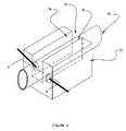
- FIG. 2is a perspective view of the sensor head having ultrasonic transmitter and receiving crystal elements
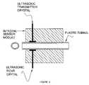
- FIG. 3is a top view in cross-section of the sensor head along lines 3 - 3 of FIG. 2 ;
- FIG. 4is a block diagram of the system electronics
- FIG. 5is a timing diagram showing the change in amplitude and shift in ultrasonic energy travel time due to a change in internal tube fluid pressure
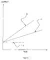
- FIG. 6is a graph illustrating rate of change of tube deformation due to tube creep and pressure change.
- the systemhas a sensor head 10 similar to that described with respect to FIG. 1 .
- the head 10 of the non-invasive sensoris a block of a plastic material such as UDELL polysulfone resin manufactured by Solvay Advanced Polymers.
- the head 10is illustratively shown as being of a generally rectangular shape and can be molded by any suitable technique.
- In the head 10there is a longitudinal slot 12 that has opposing side walls 14 and 16 .
- a tube 20 of flexible and elastically outwardly expansible material having a liquid flowing in itis to be placed in the slot 12 .
- Typical materials for the tubeare silicone, vinyl plastic, polyethylene or flexible TEFLON, with the latter two materials being somewhat more rigid than the first two.
- the tube 20typically is to have one end connected to the body of a patient and the other end connected to a liquid supply, such as a medicine or saline solution in a suspended bag, or to a machine such as a dialysis machine or a blood pump.
- a liquid supplysuch as a medicine or saline solution in a suspended bag
- a machinesuch as a dialysis machine or a blood pump.
- a pair of depressionsare preferably formed in the opposing slot side walls 14 and 16 in which piezoelectric sensor elements, or crystals, are to be mounted.
- the slot side wall thicknessis typically 0.30′′ to 0.050′′ depending upon the diameter of the tube used.
- a holeis drilled through the outside walls of the head 10 to each of the depressions in the slot sidewalls 14 and 16 to accommodate a respective lead wire or wires connected to the respective sensor element.
- a pair of piezoelectric elements 26 a and 26 bare mounted opposing each other in the depressions in the opposing slot side walls 14 and 16 .
- the front face of each elementpreferably extends out of the side wall for a small distance.
- One of the piezoelectric elements 26 aacts as a transmitter of ultrasonic energy and the other 26 b as a receiver of the transmitted energy.
- Both piezoelectric elementsare of commercially available PZT type material or other suitable piezoelectric material.
- the transmitter element 26 ais supplied energy at an operating frequency range from 2 MHZ to 5 MHZ.
- the plastic tube 20is laid in the slot 12 .
- the width of the slot 12is slightly less than the outer diameter of the plastic tube 20 so that the front faces of the piezoelectric elements 26 a and 26 b mounted in the opposing slot side walls 14 and 16 make contact with the tube 20 .
- a typical deformation, or squeeze, of the tube in the slotwould be 15% to 20% of the tube outer diameter.
- This arrangementpermits satisfactory operation of the piezoelectric elements without the use of a coupling compound such as petroleum jelly.
- no soft faceis needed for the elements such as is needed for the strain gage.
- the elements 26 a and 26 bare preferably mounted so as to engage the widest cross dimension, or diameter, of the tube 20 when it is laid in the slot 12 .
- FIG. 4shows the electronic components of the system.
- a microprocessor 50that is suitably programmed to perform all of the functions described below.
- An output of the microprocessor on line 51is supplied to one input of an AND gate 52 whose other input is from a clock pulse generator 53 .
- the microprocessorperiodically gates open the AND gate 52 for a predetermined time so that bursts of the clock pulses, which illustratively are at a frequency of 2-5 MHZ, are applied to a transmitter pulse driver 54 which supplies pulses of electrical energy to the transmitter piezoelectric element, here shown as element 26 a .
- Element 26 aconverts the electrical energy to electro-mechanical energy which is transmitted through the wall of the tube 20 , through the interior of the tube and any liquid flowing through it, and out through the other side of the tube to be received by the piezoelectric receiving element 26 b .
- Element 26 bconverts the electro-mechanical energy to an electrical signal that is amplified by a high gain amplifier 56 . As discussed below, the travel time of the energy between the two elements 26 a and 26 b and the amplitude of the signal at the amplifier 56 is related to the pressure of the liquid flowing in the tube 20 .
- the analog output signal from amplifier 56is applied to the input of an analog to digital converter 58 whose output is supplied to the microprocessor 50 for processing.
- the microprocessorhas an output that can be to a visual display, alarm or another signal line.
- FIG. 5shows the operation of the system to measure pressure changes of the liquid in the tube 20 .
- the top line A of elapsed timeshows the bursts of energy applied to the transmitter piezoelectric element 26 a when the AND gate 52 of the circuit of FIG. 4 is gated open. During the time between the bursts, the energy transmitted from piezoelectric element 26 a travels through the tube 20 and is received by the piezoelectric element 26 b .
- the lower line B of elapsed timeshows the travel time of the energy and the amplitude of the received signal. The travel time is measured by the microprocessor 50 using its internal clock starting from the transmission of cycle of the transmitted energy burst.
- the solid line Cshows the received signal at the output of the element 26 b when the pressure of the liquid in the tube 20 is steady.
- the transmitted energyis received after a travel time t 0 through the tube.
- the received signalis amplified by the amplifier 56 of FIG. 4 and applied to the analog to digital converter 58 .
- the digital values of the travel time t 0 and the amplitude of curve Care applied to the microprocessor 50 and stored as base line values.
- the signal resulting from a pressure increaseis received at time t 1 which is later than the time t 0 .
- the amplitude of the signal of line Dis greater than that of line C.
- the signal of line Dwhich includes its travel time and amplitude, is digitized by the analog to digital converter 58 and applied to the microprocessor 50 .
- the digital values ⁇ t and the signal amplitudes of lines C and Dare available for processing by the microprocessor 50 and each can be converted to a pressure change value.
- the signal amplitude and travel timeare determined by the microprocessor 50 periodically at every energy burst transmit cycle.
- the microprocessoralso has stored initial base line values of the signal at a normal internal pressure of the liquid. If desired, these initial values can be pre-programmed into the microprocessor.
- the timing difference ⁇ t between signals at normal and increased pressurecan be very precisely computed.
- a small change in amplitude of the signalsalso can be measured. That is, each of the differences of travel time and amplitude to the base line values can be used to determine the occurrence and/or numerical value, in psi or other unit, of the pressure change.
- a cross correlation techniquecan be used by the microprocessor to obtain an average between the two numerical values.
- a displayalso can be operated by the microprocessor 50 to display the measured pressure value, that is, the change from the base line value. In some applications, it is only necessary to show that a pressure change has occurred and the numerical amount of change is not of importance.
- the base line values of signal travel time and amplitude used by the microprocessorare those of liquid flowing in the tube at a normal pressure.
- the base line valuesalso can be those taken when there is no liquid flowing in the tube.
- shifting or dynamic base line valueswould be used as compared to the static values described above. That is, the microprocessor would make a comparison based on the travel time and amplitude values determined for a burst of ultrasonic energy transmitted during a prior cycle. It also is possible to use firm initial base line values and shifting values to provide both changes from the initial base line values and continuing dynamic pressure changes.
- the microprocessoralso can be programmed to increase pressure change measurement accuracy by providing it with data of tube “creep”. All of flexible material exhibit a creep behavior due to a material relaxation phenomena. This is shown in FIG. 6 .
- the amplitude of the signal received by piezoelectric crystal receiver element 26 bis at fixed DC voltage, represented by the line E of FIG. 6 .
- the wall of a tubeexpands and more firmly engages the slot side walls and the piezoelectric elements. This results in an increase in received signal amplitude as a function of a time, which is represented by line F.
- the tube wall relaxationalso continues to occur during the tube internal pressure change but at a greater rate as shown by line G of FIG. 6 .
- the degree of the slope of lines F and Gis illustrative and varies depending upon the characteristics of tube material. Measurements of the rate of change in signal amplitude due to pressure change vs creeping phenomena can be used to refine the base line pressure measurement values and the dynamic values.
- the creep signal information for a given tubewould be determined and would be programmed into the microprocessor, such as by being added to the static or dynamic base line values, to be used to refine the measurement of both the signal travel time and amplitude.
- the ultrasonic system of the inventionalso provides other useful information of operation in addition to determining a change in pressure.
- the constant output voltage of line Eis indicative of a proper functional behavior of a complete system. For example, if a piezoelectric crystal element or electronic circuit component failed or the tube was not in the slot, then the DC signal would not be present. This provides a continuous self check of proper system operation.
- the ultrasonic of the inventionis based on the rate of propagation of ultrasonic energy inside the liquid. It measures both amplitude and time shift and calculate the change of fluid pressure. Also it does not require the soft front face of a strain gage to couple with the tubing.
Landscapes
- Physics & Mathematics (AREA)
- General Physics & Mathematics (AREA)
- Measuring Fluid Pressure (AREA)
Abstract
Description
Claims (21)
Priority Applications (1)
| Application Number | Priority Date | Filing Date | Title |
|---|---|---|---|
| US11/983,328US7617739B1 (en) | 2007-11-08 | 2007-11-08 | Non-invasive ultrasonic system to determine internal pressure in flexible tubing |
Applications Claiming Priority (1)
| Application Number | Priority Date | Filing Date | Title |
|---|---|---|---|
| US11/983,328US7617739B1 (en) | 2007-11-08 | 2007-11-08 | Non-invasive ultrasonic system to determine internal pressure in flexible tubing |
Publications (1)
| Publication Number | Publication Date |
|---|---|
| US7617739B1true US7617739B1 (en) | 2009-11-17 |
Family
ID=41279552
Family Applications (1)
| Application Number | Title | Priority Date | Filing Date |
|---|---|---|---|
| US11/983,328Expired - Fee RelatedUS7617739B1 (en) | 2007-11-08 | 2007-11-08 | Non-invasive ultrasonic system to determine internal pressure in flexible tubing |
Country Status (1)
| Country | Link |
|---|---|
| US (1) | US7617739B1 (en) |
Cited By (14)
| Publication number | Priority date | Publication date | Assignee | Title |
|---|---|---|---|---|
| US20130061687A1 (en)* | 2011-09-12 | 2013-03-14 | Hydrosonic B.V. | Portable ultrasonic flow measuring system, measuring devices and measuring tube |
| CN103630288A (en)* | 2013-11-28 | 2014-03-12 | 江苏大学 | Ultrasonic recycling triggered pressure measuring device and method |
| US9505233B2 (en) | 2014-10-10 | 2016-11-29 | Becton, Dickinson And Company | Tensioning control device |
| US9514131B1 (en) | 2010-05-30 | 2016-12-06 | Crisi Medical Systems, Inc. | Medication container encoding, verification, and identification |
| US9615999B2 (en) | 2011-06-16 | 2017-04-11 | Crisi Medical Systems, Inc. | Medication dose preparation and transfer system |
| US9744298B2 (en) | 2011-06-22 | 2017-08-29 | Crisi Medical Systems, Inc. | Selectively controlling fluid flow through a fluid pathway |
| US9776757B2 (en) | 2014-10-10 | 2017-10-03 | Becton, Dickinson And Company | Syringe labeling device |
| US9931498B2 (en) | 2013-03-13 | 2018-04-03 | Crisi Medical Systems, Inc. | Injection site information cap |
| US20180299305A1 (en)* | 2017-04-13 | 2018-10-18 | Sick Engineering Gmbh | Measurement apparatus for measuring a flow rate of a fluid |
| US10245214B2 (en) | 2010-04-27 | 2019-04-02 | Crisi Medical Systems, Inc. | Medication and identification information transfer apparatus |
| US10293107B2 (en) | 2011-06-22 | 2019-05-21 | Crisi Medical Systems, Inc. | Selectively Controlling fluid flow through a fluid pathway |
| US10492991B2 (en) | 2010-05-30 | 2019-12-03 | Crisi Medical Systems, Inc. | Medication container encoding, verification, and identification |
| US10503873B2 (en) | 2009-11-06 | 2019-12-10 | Crisi Medical Systems, Inc. | Medication injection site and data collection system |
| JP2020056639A (en)* | 2018-10-01 | 2020-04-09 | 富士電機株式会社 | Pressure measuring device |
Citations (7)
| Publication number | Priority date | Publication date | Assignee | Title |
|---|---|---|---|---|
| US4807479A (en)* | 1987-03-06 | 1989-02-28 | Daikin Industries, Ltd. | Transducer for detecting pressure changes in pipes |
| US5031460A (en)* | 1989-01-31 | 1991-07-16 | Daikin Industries, Ltd. | Transducer for detecting pressure changes in pipes |
| US6030343A (en)* | 1997-09-03 | 2000-02-29 | Pgvc Lp | Single beam tone burst ultrasonic non contact tonometer and method of measuring intraocular pressure |
| JP2001165748A (en)* | 1999-12-09 | 2001-06-22 | Yazaki Corp | Gas meter |
| US7109720B2 (en)* | 2001-12-21 | 2006-09-19 | Schneider Electric Industries Sas | Method for determining wear of a switchgear contacts |
| US7240553B2 (en)* | 2002-06-14 | 2007-07-10 | Consejo Superior De Investigaciones Cientificas (Csic) | Non-invasive detection and analysis of microorganisms in diary products packaged in paper or paperboard based laminated recipients using dry coupling elastic waves |
| US7290450B2 (en)* | 2003-07-18 | 2007-11-06 | Rosemount Inc. | Process diagnostics |
- 2007
- 2007-11-08USUS11/983,328patent/US7617739B1/ennot_activeExpired - Fee Related
Patent Citations (7)
| Publication number | Priority date | Publication date | Assignee | Title |
|---|---|---|---|---|
| US4807479A (en)* | 1987-03-06 | 1989-02-28 | Daikin Industries, Ltd. | Transducer for detecting pressure changes in pipes |
| US5031460A (en)* | 1989-01-31 | 1991-07-16 | Daikin Industries, Ltd. | Transducer for detecting pressure changes in pipes |
| US6030343A (en)* | 1997-09-03 | 2000-02-29 | Pgvc Lp | Single beam tone burst ultrasonic non contact tonometer and method of measuring intraocular pressure |
| JP2001165748A (en)* | 1999-12-09 | 2001-06-22 | Yazaki Corp | Gas meter |
| US7109720B2 (en)* | 2001-12-21 | 2006-09-19 | Schneider Electric Industries Sas | Method for determining wear of a switchgear contacts |
| US7240553B2 (en)* | 2002-06-14 | 2007-07-10 | Consejo Superior De Investigaciones Cientificas (Csic) | Non-invasive detection and analysis of microorganisms in diary products packaged in paper or paperboard based laminated recipients using dry coupling elastic waves |
| US7290450B2 (en)* | 2003-07-18 | 2007-11-06 | Rosemount Inc. | Process diagnostics |
Non-Patent Citations (2)
| Title |
|---|
| J. Webster (ed.), Wiley Encyclopedia of Electrical and Electronics Engineering, Flowmeters, Copyright # 1999 John Wiley & Sons, Inc.* |
| J. Webster (ed.), Wiley Encyclopedia of Electrical and Electronics Engineering, Pressure Sensors. Copyright-c 1999 John Wiley & Sons, Inc.* |
Cited By (36)
| Publication number | Priority date | Publication date | Assignee | Title |
|---|---|---|---|---|
| US11690958B2 (en) | 2009-11-06 | 2023-07-04 | Crisi Medical Systems, Inc. | Medication injection site and data collection system |
| US10503873B2 (en) | 2009-11-06 | 2019-12-10 | Crisi Medical Systems, Inc. | Medication injection site and data collection system |
| US10245214B2 (en) | 2010-04-27 | 2019-04-02 | Crisi Medical Systems, Inc. | Medication and identification information transfer apparatus |
| US11801201B2 (en) | 2010-04-27 | 2023-10-31 | Crisi Medical Systems, Inc. | Medication and identification information transfer apparatus |
| US10751253B2 (en) | 2010-04-27 | 2020-08-25 | Crisi Medical Systems, Inc. | Medication and identification information transfer apparatus |
| US12274672B2 (en) | 2010-04-27 | 2025-04-15 | Crisi Medical Systems, Inc. | Medication and identification information transfer apparatus |
| US10813836B2 (en) | 2010-05-30 | 2020-10-27 | Crisi Medical Systems, Inc. | Medication container encoding, verification, and identification |
| US9514131B1 (en) | 2010-05-30 | 2016-12-06 | Crisi Medical Systems, Inc. | Medication container encoding, verification, and identification |
| US12295913B2 (en) | 2010-05-30 | 2025-05-13 | Crisi Medical Systems, Inc. | Medication container encoding, verification, and identification |
| US10492991B2 (en) | 2010-05-30 | 2019-12-03 | Crisi Medical Systems, Inc. | Medication container encoding, verification, and identification |
| US10327987B1 (en) | 2010-05-30 | 2019-06-25 | Crisi Medical Systems, Inc. | Medication container encoding, verification, and identification |
| US10391033B2 (en) | 2011-06-16 | 2019-08-27 | Crisi Medical Systems, Inc. | Medication dose preparation and transfer system |
| US11464708B2 (en) | 2011-06-16 | 2022-10-11 | Crisi Medical Systems, Inc. | Medication dose preparation and transfer system |
| US9615999B2 (en) | 2011-06-16 | 2017-04-11 | Crisi Medical Systems, Inc. | Medication dose preparation and transfer system |
| US12343311B2 (en) | 2011-06-16 | 2025-07-01 | Crisi Medical Systems, Inc. | Medication dose preparation and transfer system |
| US10532154B2 (en) | 2011-06-22 | 2020-01-14 | Crisi Medical Systems, Inc. | Selectively controlling fluid flow through a fluid pathway |
| US10293107B2 (en) | 2011-06-22 | 2019-05-21 | Crisi Medical Systems, Inc. | Selectively Controlling fluid flow through a fluid pathway |
| US11464904B2 (en) | 2011-06-22 | 2022-10-11 | Crisi Medical Systems, Inc. | Selectively controlling fluid flow through a fluid pathway |
| US9744298B2 (en) | 2011-06-22 | 2017-08-29 | Crisi Medical Systems, Inc. | Selectively controlling fluid flow through a fluid pathway |
| US20130061687A1 (en)* | 2011-09-12 | 2013-03-14 | Hydrosonic B.V. | Portable ultrasonic flow measuring system, measuring devices and measuring tube |
| US9188468B2 (en)* | 2011-09-12 | 2015-11-17 | Hydeosonic B.V. | Portable ultrasonic flow measuring system having a measuring device with adjustable sensor heads relative to each other |
| US10143830B2 (en) | 2013-03-13 | 2018-12-04 | Crisi Medical Systems, Inc. | Injection site information cap |
| US9931498B2 (en) | 2013-03-13 | 2018-04-03 | Crisi Medical Systems, Inc. | Injection site information cap |
| US11717667B2 (en) | 2013-03-13 | 2023-08-08 | Crisi Medical Systems, Inc. | Injection site information cap |
| US10420926B2 (en) | 2013-03-13 | 2019-09-24 | Crisi Medical Systems, Inc. | Injection site information cap |
| US10946184B2 (en) | 2013-03-13 | 2021-03-16 | Crisi Medical Systems, Inc. | Injection site information cap |
| CN103630288A (en)* | 2013-11-28 | 2014-03-12 | 江苏大学 | Ultrasonic recycling triggered pressure measuring device and method |
| US10661935B2 (en) | 2014-10-10 | 2020-05-26 | Becton, Dickinson And Company | Syringe labeling device |
| US10954019B2 (en) | 2014-10-10 | 2021-03-23 | Becton, Dickinson And Company | Tensioning control device |
| US10220974B2 (en) | 2014-10-10 | 2019-03-05 | Becton, Dickinson And Company | Syringe labeling device |
| US9505233B2 (en) | 2014-10-10 | 2016-11-29 | Becton, Dickinson And Company | Tensioning control device |
| US9776757B2 (en) | 2014-10-10 | 2017-10-03 | Becton, Dickinson And Company | Syringe labeling device |
| US10220973B2 (en) | 2014-10-10 | 2019-03-05 | Becton, Dickinson And Company | Tensioning control device |
| US20180299305A1 (en)* | 2017-04-13 | 2018-10-18 | Sick Engineering Gmbh | Measurement apparatus for measuring a flow rate of a fluid |
| US10488237B2 (en)* | 2017-04-13 | 2019-11-26 | Sick Engineering Gmbh | Measurement apparatus for measuring a flow rate of a fluid |
| JP2020056639A (en)* | 2018-10-01 | 2020-04-09 | 富士電機株式会社 | Pressure measuring device |
Similar Documents
| Publication | Publication Date | Title |
|---|---|---|
| US7617739B1 (en) | Non-invasive ultrasonic system to determine internal pressure in flexible tubing | |
| US7661294B2 (en) | Non-invasive multi-function sensor system | |
| US8857269B2 (en) | Method of varying the flow rate of fluid from a medical pump and hybrid sensor system performing the same | |
| RU2218090C2 (en) | Method and device for determining intracerebral pressure | |
| US6631639B1 (en) | System and method of non-invasive discreet, continuous and multi-point level liquid sensing using flexural waves | |
| US4600855A (en) | Piezoelectric apparatus for measuring bodily fluid pressure within a conduit | |
| US6773407B2 (en) | Non-invasive method of determining absolute intracranial pressure | |
| US5303585A (en) | Fluid volume sensor | |
| US7833160B2 (en) | Blood viscosity measurement device | |
| KR920017623A (en) | Arterial Hardness Observer | |
| US8694271B2 (en) | Apparatus and method for non invasive measurement of properties of a fluid flowing in a flexible tubing or conduit | |
| US8844359B2 (en) | Apparatus for noninvasive measurement of properties of a fluid flowing in a tubing having a smaller inner diameter passage | |
| US20040025592A1 (en) | Continuous wave ultrasonic process monitor for polymer processing | |
| US20250109976A1 (en) | Gas volume determination in fluid | |
| US20060278293A1 (en) | Pressure measuring line, particularly for invasive blood pressure measurement | |
| JP2008507707A (en) | Method and apparatus for simultaneous pressure and temperature determination in high pressure tanks by ultrasonic propagation time measurement | |
| KR102490359B1 (en) | Combined ultrasonic temperature and conductivity sensor assembly | |
| KR100338436B1 (en) | A medical sensor for detecting pulses | |
| JP3047104U (en) | Pressure transmitter with fill fluid loss detector | |
| CN116261423A (en) | Estimating central blood pressure | |
| JP2015143632A (en) | Ultrasonic measuring device and ultrasonic measuring method | |
| JP6235262B2 (en) | Measuring method of pressure change of an object that causes pressure change on the surface | |
| JPH0371653B2 (en) | ||
| JP2014005755A (en) | Liquid feeding pump and circulating device |
Legal Events
| Date | Code | Title | Description |
|---|---|---|---|
| AS | Assignment | Owner name:COSENSE, INC., NEW YORK Free format text:ASSIGNMENT OF ASSIGNORS INTEREST;ASSIGNOR:DAM, NAIM;REEL/FRAME:020158/0543 Effective date:20070130 | |
| STCF | Information on status: patent grant | Free format text:PATENTED CASE | |
| FEPP | Fee payment procedure | Free format text:PAYOR NUMBER ASSIGNED (ORIGINAL EVENT CODE: ASPN); ENTITY STATUS OF PATENT OWNER: LARGE ENTITY | |
| AS | Assignment | Owner name:MEASUREMENT SPECIALTIES, INC., VIRGINIA Free format text:ASSIGNMENT OF ASSIGNORS INTEREST;ASSIGNOR:COSENSE, INC.;REEL/FRAME:027977/0272 Effective date:20120402 | |
| FEPP | Fee payment procedure | Free format text:PAT HOLDER NO LONGER CLAIMS SMALL ENTITY STATUS, ENTITY STATUS SET TO UNDISCOUNTED (ORIGINAL EVENT CODE: STOL); ENTITY STATUS OF PATENT OWNER: LARGE ENTITY | |
| AS | Assignment | Owner name:JPMORGAN CHASE BANK, N.A., AS COLLATERAL AGENT, IL Free format text:SECURITY AGREEMENT;ASSIGNOR:MEASUREMENT SPECIALTIES, INC.;REEL/FRAME:029660/0543 Effective date:20130118 | |
| FPAY | Fee payment | Year of fee payment:4 | |
| AS | Assignment | Owner name:MEASUREMENT SPECIALTIES, INC., VIRGINIA Free format text:RELEASE OF PATENT SECURITY INTEREST;ASSIGNOR:JPMORGAN CHASE BANK, N.A., AS COLLATERAL AGENT;REEL/FRAME:034104/0391 Effective date:20141009 | |
| FPAY | Fee payment | Year of fee payment:8 | |
| FEPP | Fee payment procedure | Free format text:MAINTENANCE FEE REMINDER MAILED (ORIGINAL EVENT CODE: REM.); ENTITY STATUS OF PATENT OWNER: LARGE ENTITY | |
| LAPS | Lapse for failure to pay maintenance fees | Free format text:PATENT EXPIRED FOR FAILURE TO PAY MAINTENANCE FEES (ORIGINAL EVENT CODE: EXP.); ENTITY STATUS OF PATENT OWNER: LARGE ENTITY | |
| STCH | Information on status: patent discontinuation | Free format text:PATENT EXPIRED DUE TO NONPAYMENT OF MAINTENANCE FEES UNDER 37 CFR 1.362 | |
| FP | Lapsed due to failure to pay maintenance fee | Effective date:20211117 |