US7616444B2 - Gimballed attachment for multiple heat exchangers - Google Patents
Gimballed attachment for multiple heat exchangersDownload PDFInfo
- Publication number
- US7616444B2 US7616444B2US11/800,101US80010107AUS7616444B2US 7616444 B2US7616444 B2US 7616444B2US 80010107 AUS80010107 AUS 80010107AUS 7616444 B2US7616444 B2US 7616444B2
- Authority
- US
- United States
- Prior art keywords
- heat
- joining system
- gimbal
- coupled
- heat exchanger
- Prior art date
- Legal status (The legal status is an assumption and is not a legal conclusion. Google has not performed a legal analysis and makes no representation as to the accuracy of the status listed.)
- Expired - Lifetime
Links
- 230000007246mechanismEffects0.000claimsabstractdescription60
- 230000014759maintenance of locationEffects0.000claimsabstractdescription38
- 230000013011matingEffects0.000claimsabstractdescription30
- 230000008878couplingEffects0.000claimsdescription12
- 238000010168coupling processMethods0.000claimsdescription12
- 238000005859coupling reactionMethods0.000claimsdescription12
- 230000000712assemblyEffects0.000claimsdescription3
- 238000000429assemblyMethods0.000claimsdescription3
- 238000002347injectionMethods0.000claimsdescription2
- 239000007924injectionSubstances0.000claimsdescription2
- 230000000087stabilizing effectEffects0.000claims4
- 239000012530fluidSubstances0.000claims1
- 238000001816coolingMethods0.000description15
- 239000000463materialSubstances0.000description8
- 238000000034methodMethods0.000description5
- 239000004065semiconductorSubstances0.000description5
- 239000007788liquidSubstances0.000description4
- 238000009434installationMethods0.000description2
- 239000000243solutionSubstances0.000description2
- 229910000639Spring steelInorganic materials0.000description1
- 238000010276constructionMethods0.000description1
- 230000008602contractionEffects0.000description1
- 238000012986modificationMethods0.000description1
- 230000004048modificationEffects0.000description1
- 229920000642polymerPolymers0.000description1
- 230000001105regulatory effectEffects0.000description1
Images


Classifications
- H—ELECTRICITY
- H01—ELECTRIC ELEMENTS
- H01L—SEMICONDUCTOR DEVICES NOT COVERED BY CLASS H10
- H01L23/00—Details of semiconductor or other solid state devices
- H01L23/34—Arrangements for cooling, heating, ventilating or temperature compensation ; Temperature sensing arrangements
- H01L23/42—Fillings or auxiliary members in containers or encapsulations selected or arranged to facilitate heating or cooling
- H01L23/427—Cooling by change of state, e.g. use of heat pipes
- F—MECHANICAL ENGINEERING; LIGHTING; HEATING; WEAPONS; BLASTING
- F28—HEAT EXCHANGE IN GENERAL
- F28D—HEAT-EXCHANGE APPARATUS, NOT PROVIDED FOR IN ANOTHER SUBCLASS, IN WHICH THE HEAT-EXCHANGE MEDIA DO NOT COME INTO DIRECT CONTACT
- F28D15/00—Heat-exchange apparatus with the intermediate heat-transfer medium in closed tubes passing into or through the conduit walls ; Heat-exchange apparatus employing intermediate heat-transfer medium or bodies
- F28D15/02—Heat-exchange apparatus with the intermediate heat-transfer medium in closed tubes passing into or through the conduit walls ; Heat-exchange apparatus employing intermediate heat-transfer medium or bodies in which the medium condenses and evaporates, e.g. heat pipes
- F28D15/0275—Arrangements for coupling heat-pipes together or with other structures, e.g. with base blocks; Heat pipe cores
- H—ELECTRICITY
- H01—ELECTRIC ELEMENTS
- H01L—SEMICONDUCTOR DEVICES NOT COVERED BY CLASS H10
- H01L23/00—Details of semiconductor or other solid state devices
- H01L23/34—Arrangements for cooling, heating, ventilating or temperature compensation ; Temperature sensing arrangements
- H01L23/40—Mountings or securing means for detachable cooling or heating arrangements ; fixed by friction, plugs or springs
- H—ELECTRICITY
- H01—ELECTRIC ELEMENTS
- H01L—SEMICONDUCTOR DEVICES NOT COVERED BY CLASS H10
- H01L23/00—Details of semiconductor or other solid state devices
- H01L23/34—Arrangements for cooling, heating, ventilating or temperature compensation ; Temperature sensing arrangements
- H01L23/42—Fillings or auxiliary members in containers or encapsulations selected or arranged to facilitate heating or cooling
- H01L23/433—Auxiliary members in containers characterised by their shape, e.g. pistons
- H01L23/4338—Pistons, e.g. spring-loaded members
- H—ELECTRICITY
- H01—ELECTRIC ELEMENTS
- H01L—SEMICONDUCTOR DEVICES NOT COVERED BY CLASS H10
- H01L23/00—Details of semiconductor or other solid state devices
- H01L23/34—Arrangements for cooling, heating, ventilating or temperature compensation ; Temperature sensing arrangements
- H01L23/40—Mountings or securing means for detachable cooling or heating arrangements ; fixed by friction, plugs or springs
- H01L23/4006—Mountings or securing means for detachable cooling or heating arrangements ; fixed by friction, plugs or springs with bolts or screws
- H01L2023/4075—Mechanical elements
- H01L2023/4081—Compliant clamping elements not primarily serving heat-conduction
- H—ELECTRICITY
- H01—ELECTRIC ELEMENTS
- H01L—SEMICONDUCTOR DEVICES NOT COVERED BY CLASS H10
- H01L23/00—Details of semiconductor or other solid state devices
- H01L23/34—Arrangements for cooling, heating, ventilating or temperature compensation ; Temperature sensing arrangements
- H01L23/40—Mountings or securing means for detachable cooling or heating arrangements ; fixed by friction, plugs or springs
- H01L23/4006—Mountings or securing means for detachable cooling or heating arrangements ; fixed by friction, plugs or springs with bolts or screws
- H01L2023/4075—Mechanical elements
- H01L2023/4087—Mounting accessories, interposers, clamping or screwing parts
- H—ELECTRICITY
- H01—ELECTRIC ELEMENTS
- H01L—SEMICONDUCTOR DEVICES NOT COVERED BY CLASS H10
- H01L2924/00—Indexing scheme for arrangements or methods for connecting or disconnecting semiconductor or solid-state bodies as covered by H01L24/00
- H01L2924/0001—Technical content checked by a classifier
- H01L2924/0002—Not covered by any one of groups H01L24/00, H01L24/00 and H01L2224/00
Definitions
- the inventionrelates to a method and apparatus for joining two interfaces.
- the inventionrelates to a semi-compliant joining mechanism used to join a heat collecting apparatus and a heat generating source in semiconductor cooling applications.
- cooling systemsAs integrated circuits increase in size and complexity, dissipating the increasing amount of heat being generated by these integrated circuits is critical. As the high end for thermal solutions increases, so does the size of the cooling systems used to provide such thermal solutions. Unfortunately, larger cooling systems include more mass. Where a thermal interface is necessary, mounting such a cooling system becomes more challenging and often leads to damage of the cooling system or surrounding components, including the integrated circuit to be cooled.
- the thermal resistance of the thermal interface materialcontributes to the overall thermal resistance. Wide variations in the values of the thermal interface material resistance can exist.
- Non-uniform thickness of the thermal interface materialoften result due to the mounting process, thereby resulting in a non-uniform thermal resistance across the thermal interface. If a uni-directional force is used to engage the heat exchanger to the heat source, any non-parallel configuration or alignment of either mating surface will result in an uneven thermal interface between the two.
- a joining systemincludes a plurality of heat generating devices mounted to a mounting apparatus, a plurality of heat exchangers, each heat exchanger coupled to a corresponding heat generating device, and a gimbal retention mechanism including a plurality of gimbal joints and one or more spring means, wherein the one or more spring means couple the gimbal retention mechanism to the mounting apparatus, and the plurality of gimbal joints couple the gimbal retention mechanism to the plurality of heat exchangers thereby coupling each heat exchanger to the corresponding heat generating device.
- a joining systemin another aspect, includes a heat generating device mounted to a mounting apparatus, a heat rejector coupled to the heat generating device, wherein the heat rejector includes a plurality of fins, and a gimbal retention mechanism including a gimbal joint and one or more spring means, wherein the gimbal joint is coupled to the heat rejector and the one or more spring means are coupled to the mounting apparatus, thereby coupling the heat rejector to the heat generating device.
- a joining systemin yet another aspect, includes a heat generating device mounted to a mounting apparatus, a heat pipe assembly coupled to the heat generating device, wherein the heat pipe assembly includes a heat spreader coupled to the heat generating device, one or more heat pipes coupled to the heat spreader, and a plurality of fins coupled to the one or more heat pipes, and a gimbal retention mechanism including a gimbal joint and one or more spring means, wherein the gimbal joint is coupled to the heat spreader and the one or more spring means are coupled to the mounting apparatus, thereby coupling the heat rejector to the heat generating device.
- FIG. 1illustrates a joining mechanism configured to couple a single heat exchanger to a single heat source.
- FIG. 2illustrates a joining mechanism configured to couple two heat exchangers to two heat sources using a single joining mechanism.
- FIG. 3illustrates a joining mechanism configured to couple four heat exchangers to four heat sources using a single joining mechanism.
- FIG. 4Aillustrates a first exemplary heat exchanger configuration
- FIG. 4Billustrates an exploded view of the heat exchanger configuration of FIG. 4A .
- FIG. 5Aillustrates a second exemplary heat exchanger configuration.
- FIG. 5Billustrates an exploded view of the heat exchanger configuration of FIG. 5A .
- FIG. 6Aillustrates a third exemplary heat exchanger configuration.
- FIG. 6Billustrates an exploded view of the heat exchanger configuration of FIG. 6A .
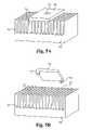
- FIG. 7Aillustrates a fourth exemplary heat exchanger configuration.
- FIG. 7Billustrates a partially exploded view of the heat pipe assembly of FIG. 7A .
- FIG. 8Aillustrates a fifth exemplary heat exchanger configuration.
- FIG. 8Billustrates a perspective view of the heat pipe assembly of FIG. 8A .
- FIG. 9illustrates a sixth exemplary heat exchanger configuration.
- FIG. 10illustrates a seventh exemplary heat exchanger configuration.
- FIG. 11illustrates a cross-sectional view of a first configuration for coupling each mounting stand to the circuit board.
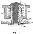
- FIG. 12illustrates a cross-sectional view of a second configuration for coupling each mounting stand to the circuit board.
- FIG. 13illustrates a side view of an exemplary configuration of a gimbal post and gimbal plate modified to include spring means.
- Embodiments of the present inventioninclude a semi-compliant joining mechanism used for generating repairable low thermal resistance interfaces between a heat exchanging device and a heat generating source.
- the interfacesare preferably used in semiconductor cooling applications.
- references to a heat exchanging device, a heat exchanging apparatus, a heat collector, a micro-heat exchanger, a heat exchanger, and the likeare used interchangeably and refer in general to any apparatus capable of exchanging heat with an external heat source.
- a heat exchanging deviceexamples include, but are not limited to, an extruded fin heat sink, a crimped fin heat sink, a heat pipe assembly, a vapor chamber, a thermal siphon, a micro-channel heat exchanger as part of a liquid cooling system, a cold plate as part of a liquid cooling system, an injection molded heat sink, or a forged heat sink.
- references to a heat source, a heat generating source, a heat generating device, and the like, as well as specific references to exemplary heat generating devices such as an integrated circuit, an integrated microprocessor circuit, and a semiconductor heat sourceare used interchangeably and refer in general to any apparatus or source capable of generating heat.
- the joining mechanism of the present inventionis used to couple one or more heat exchanging devices to one or more corresponding heat sources, each independently coupled through a semi-compliant gimbal joint.
- the joining mechanismenables a robust, reliable, and re-workable heat transfer interface between the heat exchanging device and a heat source, such as an integrated circuit.
- the heat exchanging deviceis preferably mounted to the heat source using a gimbal plate.
- the gimbal platepreferably includes a single-point contact feature, such as a ball, a hemispherical surface, a point, or other shapes such as an ellipsoid.
- the single-point contact featurejoins with a mating feature on the heat exchanging device.
- the heat exchanging deviceincludes the single-point contact feature and the gimbal plate includes the mating feature.
- the single-point contact feature and the mating featureare collectively referred to as a gimbal joint.
- the gimbal jointenables application of a retaining force to the heat exchanging device as a single-point load.
- an application vector of the retaining forceis automatically adjusted such that the heat exchanging device self-planarizes to the heat source.
- a plane of the mating surface of the heat exchanging deviceself aligns to a plane of the mating surface of the heat source.
- the heat sourceis an integrated circuit
- the integrated circuitis mounted to a circuit board.
- the gimbal plateis preferably mounted directly to the circuit board using spring means.
- the gimbal plateis mounted to the circuit board through an intermediate bracket attached to the circuit board.
- the gimbal plateitself includes a spring force used solely or in combination with other spring means.
- An example of such a gimbal plateis a stamped spring steel plate.
- the spring meansinclude a series of fasteners (screws), springs, and/or spring plates, which regulate the amount of retaining force applied to the heat source by the heat exchanging device at the thermal interface.
- the spring meansregulates the amount of the retaining force directed through the gimbal joint to the heat exchanging device.
- the retaining forceis applied to the heat exchanging device through the gimbal-joint, forcing the mating surfaces of the heat exchanging device and the heat source together.
- the gimbal jointis rotation-compliant, the two mating faces making up the thermal interface are forced into a parallel mate.
- the two mating surfacesare unaffected by any asymmetry in the forces, such as the top mating surface of the integrated circuit being non-parallel to the circuit board to which it is mounted, that are acting on the mounting hardware of the gimbal plate.
- TIMThermal Interface Material
- FIG. 1illustrates a joining mechanism configured to couple a single heat exchanger 20 to a single heat source 40 via a force retention means, thereby forming a thermal interface 30 between the heat exchanger 20 and the heat source 40 .
- the retention forceis imparted to the heat exchanger 20 via a gimbal joint 14 .
- the gimbal joint 14is coupled to a bottom surface of a gimbal plate 10 and to a top surface of the heat exchanger 20 .
- the gimbal joint 14is configured to be rotationally-compliant.
- the heat source 40is an integrated circuit.
- the integrated circuit 40is mounted to a circuit board 50 .
- the circuit board 50can be mounted directly to a chassis (not shown) or can be mounted to one or more other circuit boards, such as a mother board, which are in turn mounted to the chassis.
- the gimbal plate 10includes a plurality of mounting stands 12 . In the preferred embodiment, there are 4 mounting stands 12 . The mounting stands 12 protrude from a bottom surface of the gimbal plate 10 . Alternatively, the gimbal plate includes 3 or more mounting stands.
- the gimbal joint 14is preferably positioned at a geometric center position of the mounting stands 12 .
- the mounting stands 12are preferably coupled to the circuit board 50 such that the gimbal joint 14 is aligned with a geometric center position of the heat exchanger 20 .
- the gimbal joint 14includes two mating components, a single-point contact and a receiver. Examples of the two mating components include, but are not limited to, a ball-in-socket, a hemispherical feature and a concave mating face, a free ball bearing between two concave hemispherical features, or a trapped ball bearing which mates with a concave hemispherical feature.
- the receivercan also be a depression in which the sides of the depression are convex. Further, the receiver can be any of the concave or convex mating faces described above with a thru-hole at a bottom portion of the depression.
- the single-point contactis a ball coupled to a first end of a post 15 , where a second end of the post 15 is coupled to a bottom surface of the gimbal plate 10 .
- the ball of the gimbal jointis coupled to a concave receiving depression on a top surface of the heat exchanger 20 .
- the ball of the gimbal joint 14is coupled directly to the bottom surface of the gimbal plate 10 and the mounting stands 12 are configured at a height such that the ball is positioned in the receiving depression on the heat exchanger.
- the single-point contactcan be a point, provided the design of the heat exchanger is robust enough to survive the force provided through the point.
- the locations of the two mating componentscan also be reversed. That is, the top surface of the heat exchanger can include the single-point contact, such as a ball secured to a top surface of the heat exchanger and a receiving depression in the bottom surface of the gimbal plate.
- the post 15is attached to a bottom surface of the gimbal plate 10 and the distance between the bottom surface of the gimbal plate 10 and the gimbal joint 14 is fixed.
- the post 15is adjustable relative to the gimbal plate 10 , therefore enabling the distance between the bottom surface of the gimbal plate 10 and the gimbal joint 14 to be varied.
- One such configurationincludes a gimbal plate with a threaded thru-hole, and a post with at least one end threaded. The post screws into the threaded thru-hole. An additional locking nut can be used to fix the threaded position of the post within the thru-hole.
- the distance between the bottom surface of the gimbal plate and the gimbal jointis adjusted by screwing or unscrewing the post. In this manner, the distance between the bottom surface of the gimbal plate and the gimbal joint can be adjusted to match the height of the receiving element on the heat exchanger.
- the gimbal plate 10includes spring means to mount the gimbal plate 10 to the circuit board 50 and to generate a retaining force which is to be directed through the gimbal joint 14 onto the heat exchanger 20 .
- the spring meansis included within the mounting stands 12 .
- An example of such spring meansis included in the co-owned U.S. patent application Ser. No. 10/945,807, filed Sep. 20, 2004, and entitled “Semi-Compliant Joining Mechanism for Semiconductor Cooling Applications” which is hereby incorporated in its entirety by reference.
- FIG. 11illustrates a cross-sectional view of a first configuration for coupling each mounting stand 12 to the circuit board 50 .
- a set of one spring 950 , one trapped plunger 940 , and one retainer ring 960is associated with each mounting stand 12 .
- Spring 950is positioned within mounting stand 12 .
- Trapped plunger 940fits within the spring 950 such that a bottom end of the trapped plunger 940 fits through a hole in the bottom of the mounting stand 12 .
- the bottom end of the trapped plunger 940is held in place by the retainer ring 960 .
- a top end of the trapped plunger 940includes a shoulder that rests on top of the spring 950 . In this first configuration, the trapper plunger 940 is internally threaded to accept a screw 944 .
- each of the trapped plungers 940include a key 942 to prevent rotation, allowing for one-tool installation from the back side of the circuit board 50 .
- FIG. 12illustrates a cross-sectional view of a second configuration for coupling each mounting stand 12 to the circuit board 50 .
- a trapped plunger 1040includes a clearance aperture 1042 through which a screw 1044 is placed. The clearance aperture 1042 is not threaded.
- the screw 1044mates with a threaded back-side plate 1046 on the circuit board 50 .
- the threaded back-side plate 1046can also be a thread nut or a threaded insert.
- a top of the screw 1044presses against the trapped plunger 1040 .
- downward pressureis applied to the trapped plunger 1040 , which contracts the spring 950 . Contraction of the spring 950 generates the retaining force.
- the second configurationenables installation of the gimbal plate 10 ( FIG. 1 ) from the front-side of the circuit board 50 .
- each set of trapped plunger 940 and spring 950contribute equally to the overall retaining force applied to the gimbal joint 14 .
- the retaining forceis regulated by the amount of thread on the trapped plunger 940 when the threads are fully engaged, and by the spring force of the spring 950 .
- the spring 950can be any type of spring, such as polymer, coil, or wavy. In this manner, a controlled amount of retaining force is provided between the heat exchanger 20 and the integrated circuit 40 .
- the circuit board 50acts as a limiter such that over tightening does not lead to excess retaining force being applied to the heat exchanger 20 . Such a fail safe prevents damage to the heat exchanger 20 or the integrated circuit 40 .
- FIG. 13illustrates a side view of an exemplary configuration of a gimbal post and gimbal plate modified to include spring means.
- the gimbal plate 10 and the post 15 from the joining mechanism of FIG. 1are modified as gimbal plate 10 ′ and gimbal post 15 ′.
- the modified gimbal plate 10 ′includes a thru-hole 17 and a locking nut 11 .
- the gimbal post 15 ′is configured to slide within the thru-hole 17 .
- the locking nut 11prevents the post 15 ′ from sliding completely through the thru-hole 17 .
- the locking nut 11is permanently affixed to the post 15 ′.
- the locking nut 11 and an end portion of the post 15 ′are threaded.
- a spring 13is coupled to the gimbal post 15 ′.
- the retention force applied through the gimbal joint 14 ( FIG. 1 )is generated by the spring 13 .
- the spring 13is compressed by forcing the post 15 ′ further into the thru-hole (upward relative to FIG. 13 ).
- the post 15 ′, and therefore the spring 13are held in this compressed position by the locking nut 11 .
- the locking nut 1 and the end portion of the post 15 ′are threaded.
- the single-point contact element of the gimbal joint 14doe not contact the receiving element on the heat exchanger 20 ( FIG. 1 ).
- the post 15 ′is released by unscrewing the locking nut 11 , thereby forcing the single-point contact element on the end of the post 15 ′ to contact the receiving element on the heat exchanger 20 .
- a method of coupling the heat exchanger 20 to the integrated circuit 40is now described in relation to FIG. 1 .
- the single point contact of the gimbal joint 14 on the post 15is placed against the receiving depression of the gimbal joint 14 on the top surface of the heat exchanger 20 .
- a bottom surface of the heat exchanger 20is placed against a top surface of the integrated circuit 40 , or a thermal interface material positioned therebetween. Due to the rotational-compliance of the gimbal joint 14 , as the heat exchanger 20 is brought into contact with the integrated circuit 40 , the gimbal joint 14 enables the bottom surface of the heat exchanger 20 to move into a substantially parallel alignment with the top surface of the integrated circuit 40 .
- a center of rotation of the receiving depression on the heat exchanger 20is preferably positioned to be collinear with the face-centered normal of the integrated circuit 40 .
- the receiving depression on the heat exchanger 20is also positioned to be collinear with the face-centered normal of the thermal interface surface of the heat exchanger 20 .
- the retaining force generated by the spring meansis directed through the gimbal joint 14 to the heat exchanger 200 . Since the center of rotation of the gimbal joint 14 is collinear with the face-centered normal lines of both the heat exchanger 200 and the integrated circuit 40 , the retaining force is applied normal to the face of the integrated circuit 40 . The retaining force moves the bottom surface of the heat exchanger 20 against the top surface of the integrated circuit 40 to form the thermal interface 30 .
- FIG. 2illustrates a joining mechanism configured to couple two heat exchangers to two heat sources using a single joining mechanism.
- the joining mechanism shown in FIG. 2is configured similarly to the joining mechanism of FIG. 1 except that the joining mechanism of FIG. 2 is configured with two gimbaling joints, which are used to coupled two heat exchangers to two corresponding heat sources.
- a single heat exchanger 120is coupled to single heat source 140 via a force retention means, thereby forming a thermal interface 130 between the heat exchanger 120 and the heat source 140 .
- a single heat exchanger 122is coupled to a single heat source 142 via the force retention means, thereby forming a thermal interface 132 between the heat exchanger 122 and the heat source 142 .
- Each of the heat sources 140 and 142are coupled to a circuit board 150 .
- the retention forceis imparted to the heat exchanger 120 via a post 115 and a gimbal joint 114 , and to the heat exchanger 122 via a post 117 and a gimbal joint 116 .
- the gimbal joint 114 and the gimbal joint 116are coupled to a bottom surface of a gimbal plate 110 .
- the gimbal joint 114 and the gimbal joint 116are each configured similarly as the gimbal joint 14 ( FIG. 1 ).
- the gimbal plate 110includes a plurality of mounting stands 112 , which are each mounted to the circuit board 150 .
- the gimbal plate 110 and mounting stands 112are mounted to the circuit board 150 in a similar manner as the gimbal plate 10 ( FIG. 1 ) and the mounting stands 12 ( FIG. 1 ) are mounted to the circuit board 50 ( FIG. 1 ), as described above.
- the resulting retaining forceis applied to each the gimbal joint 114 and the gimbal joint 116 .
- the gimbal point 114is positioned against a top surface of the heat exchanger 120
- the gimbal joint 116is positioned against a top surface of the heat exchanger 122 .
- the gimbal joint 114is preferably positioned at a geometric center position of the heat exchanger 120
- the gimbal joint 116is preferably positioned at a geometric center position of the heat exchanger 122 .
- each of the two heat exchangers 120 , 122independently planarize to their respective heat sources 140 , 142 .
- the heat exchanger 120self-planarizes to the heat source 140
- the heat exchanger 122self-planarizes to the heat source 142 , independently of each other.
- the gimballing retention force structure including the gimbal plate 110 and the mounting stands 112is a single structure as shown in FIG. 2 .
- the gimballing retention force structurehas two gimbal joints, one for each heat exchanger.
- FIG. 3illustrates a joining mechanism configured to couple four heat exchangers to four heat sources using a single joining mechanism.
- the joining mechanism shown in FIG. 3is configured similarly to and operates similarly to the joining mechanism of FIG. 2 except that the joining mechanism of FIG. 3 is configured with four gimbaling joints, which are used to coupled four heat exchangers to four corresponding heat sources.
- Each heat exchanger 220 , 221 , 222 , 223is coupled to a corresponding heat source 240 , 241 , 242 , 243 , via a force retention means, thereby forming a thermal interface 230 , 231 , 232 , 233 , respectively.
- Each of the heat sources 240 , 241 , 242 , 243are coupled to a circuit board 250 .
- the joining mechanismincludes a gimbal plate 210 and mounting stands 212 coupled to the circuit board 250 .
- the retention forceis imparted to the heat exchanger 220 via a post 201 and a gimbal joint 214 , to the heat exchanger 221 via a post 202 and a gimbal joint 215 , to the heat exchanger 222 via a post 203 and a gimbal joint 216 , and to the heat exchanger 223 via a post 204 and a gimbal joint 217 .
- the gimbal joints 214 , 215 , 216 , 217are coupled to a bottom surface of the gimbal plate 210 .
- the gimbal joints 214 , 215 , 216 , 217are each configured similarly as the gimbal joint 14 ( FIG. 1 ).
- each post shown in FIGS. 2 and 3are the same length, the actual length of each post can be customized to meet the actual height of any specific application, including the configuration where the mating surface of one or more of the heat sources are positioned at different heights relative to the mounting surface. In this case, one or more of the posts are of varied length to match the varied heights of the heat sources.
- FIGS. 4-11illustrate exemplary embodiments of various heat exchanger configurations to be implemented with the joining mechanism described above.
- an adapter platecan be used.
- the adapter plateprovides a smooth surface to receive the above mentioned retention mechanisms.
- the adapter platecan also have features to locate the adapter plate at the center of the heat sink or heat pipe assembly.
- FIG. 4Aillustrates a first exemplary heat exchanger configuration including an adapter plate 60 coupled to a heat sink 20 .
- FIG. 4Billustrates an exploded view of the heat exchanger configuration of FIG. 4A .
- the heat sink 20includes a plurality of fins 16 .
- the adapter plate 60includes a receiver element 62 to mate with a single point contact of a gimbal joint.
- the adapter plate 60is preferably configured such that the receiver element 62 is positioned in the center of the heat sink 20 .
- the receiver 62is a depression in the top surface of the adapter plate 60 .
- a width of the depressionis preferably larger than a width of the single point contact element.
- the receiver element 62is a depression with a thru-hole at the bottom of the depression.
- the width of the thru-holeis smaller than a width of the single point contact element of the gimbal joint.
- the sides of the depression surrounding the thru-holecan be concave or convex.
- the depressionis compatible with a larger range of diameters of single point contact elements since the single point contact cannot slip through the thru-hole.
- the adapter plate 60also includes locating features 64 to laterally secure the adapter plate 60 to the fins 16 . As shown in FIGS. 4A and 4B , the adapter plate 60 includes four locating features, one on each corner. Each locating feature 64 is configured to mate with an end 18 on one of the end fins 16 .
- the adapter plate 60is configured to cover the entire top surface of the fins 16 . In such a configuration, the adapter plate 60 provides an air duct past the fins 16 , resulting in enhanced thermal performance of the heat sink 20 .
- FIG. 5Aillustrates a second exemplary heat exchanger configuration including an adapter plate 70 coupled to the heat sink 20 .
- FIG. 5Billustrates an exploded view of the heat exchanger configuration of FIG. 5A .
- the adapter plate 70includes a receiver element 72 to mate with the single point contact element of the gimbal joint.
- the adapter plate 70is preferably configured such that the receiver element 72 is positioned in the center of the heat sink 20 .
- the receiver 72is a depression in the top surface of the adapter plate 70 .
- a width of the depressionis preferably larger than a width of the single point contact element.
- the receiver element 72is a depression with a thru-hole at the bottom of the depression.
- the width of the thru-holeis smaller than a width of the single point contact element of the gimbal joint.
- the sides of the depression surrounding the thru-holecan be concave or convex.
- the adapter plate 70also includes locating features 74 to laterally secure the adapter plate 70 to the fins 16 . As shown in FIGS. 5A and 5B , the adapter plate 70 includes two locating features, positioned on opposing corners. Each locating feature 74 is configured to mate with an end 22 on one of the interior fins 16 . The adapter plate 70 is configured to cover a portion of the top surface of the fins 16 .
- FIG. 6Aillustrates a third exemplary heat exchanger configuration including an adapter plate 80 coupled to the heat sink 20 .
- FIG. 6Billustrates an exploded view of the heat exchanger configuration of FIG. 6A .
- the adapter plate 80includes a receiver element 82 to mate with the single point contact of the gimbal joint.
- the adapter plate 80is preferably configured such that the receiver element 82 is positioned in the center of the heat sink 20 .
- the receiver 82is a depression in the top surface of the adapter plate 80 .
- a width of the depressionis preferably larger than a width of the single point contact element.
- the receiver element 82is a depression with a thru-hole at the bottom of the depression.
- the adapter plate 80also includes a first pair of guide rails 84 and a second pair of guide rails 86 configured to laterally secure the adapter plate 80 to the fins 16 .
- the guide rails 86are configured to align with an outer face 26 of some or all of the fins 16 .
- Each of the guide rails 84is configured to align with a lengthwise face 24 of one of the fins 16 .
- the adapter plate 80is configured to cover a portion of the top surface of the fins 16 .
- the adapter plate 60 in FIGS. 4A and 4Bcan include two locating features, as used in the adapter plate 70 ( FIGS. 5A and 5B ), instead of the four locating features shown.
- the adapter plate 70 in FIGS. 5A and 5Bcan include four locating features instead of the two locating features shown.
- the adapter plate 60can be alternatively configured to replace the locating features 64 with guide rails similar to the guide rails 84 and 86 included on the adapter plate 80 ( FIGS. 6A and 6B ).
- FIG. 7Aillustrates a fourth exemplary heat exchanger configuration including a heat pipe assembly 330 .
- the heat pipe assembly 330includes a heat spreader 332 , one or more heat pipes 334 , a plurality of fins 336 , and an adapter plate 340 .
- FIG. 7Billustrates a partially exploded view of the heat pipe assembly 330 of FIG. 7A .
- a first end of each heat pipe 334is coupled to the heat spreader 332 .
- the fins 336are coupled to the heat pipes 334 .
- a second end 338 of each heat pipe 334extends from the fins 336 and is coupled to a corresponding locating feature 344 on a bottom surface of the adapter plate 340 .
- the locating features 344 which mate to the heat pipes 334can be depressions, undersized holes that are less than the diameter of the heat pipe, or a combination of the two.
- the adapter plate 340includes a receiver element 342 to mate with a single point contact of a gimbal joint.
- the adapter plate 340is preferably configured such that the receiver element 342 is positioned in the center of the heat spreader 332 .
- the receiver 342is a depression in the top surface of the adapter plate 340 .
- a width of the depressionis preferably larger than a width of the single point contact element.
- the receiver element 342is a depression with a thru-hole at the bottom of the depression.
- the width of the thru-holeis smaller than a width of the single point contact element of the gimbal joint.
- the sides of the depression surrounding the thru-holecan be concave or convex.
- FIG. 8Aillustrates a fifth exemplary heat exchanger configuration including a heat pipe assembly 430 .
- the heat pipe assembly 430includes a heat spreader 432 , one or more heat pipes 434 , and a plurality of fins 436 .
- FIG. 8Billustrates a perspective view of the heat pipe assembly 430 of FIG. 8A .
- a first end of each heat pipe 434is coupled to the heat spreader 432 .
- the fins 436are coupled to the heat pipes 436 .
- a second end 442 of each heat pipe 434extends from a top fin 438 .
- the top fin 438includes a receiver element 440 to mate with a single point contact of a gimbal joint.
- the top fin 438is preferably configured such that the receiver element 440 is positioned in the center of the heat spreader 432 .
- the receiver 440is a depression in the top fin 338 .
- a width of the depressionis preferably larger than a width of the single point contact element.
- the receiver element 440is a depression with a thru-hole at the bottom of the depression.
- the width of the thru-holeis smaller than a width of the single point contact element of the gimbal joint.
- the sides of the depression surrounding the thru-holecan be concave or convex.
- the top fin 438is thicker than the other fins 436 in order to withstand the retention force applied via the gimbal joint.
- FIG. 9illustrates a sixth exemplary heat exchanger configuration including a heat pipe assembly 530 .
- the heat pipe assembly 530includes a heat spreader 532 , one or more heat pipes 534 , and a plurality of fins 536 .
- Each heat pipe 534is coupled to the heat spreader 532 .
- the fins 536are coupled to the heat pipes 536 .
- the top surface of the heat spreader 532includes a receiver element 533 to mate with a single point contact of a gimbal joint.
- the top surface of the heat spreader 532is the surface opposite that of the thermal interface surface of the heat spreader 532 .
- the top surface of the heat spreader 532is preferably configured such that the receiver element 533 is positioned in the center of the heat spreader 532 .
- the receiver element 533is preferably a depression in the top surface of the heat spreader 532 .
- a width of the depressionis preferably larger than a width of the single point contact element.
- FIG. 10illustrates a seventh exemplary heat exchanger configuration including a heat pipe assembly 630 .
- the heat pipe assembly 630includes a heat spreader 632 , one or more heat pipes 634 , a plurality of fins 636 , and an adapter plate 644 .
- Each heat pipe 634is coupled to the heat spreader 632 .
- the fins 636are coupled to the heat pipes 536 .
- the adapter plate 644includes a receiver element 646 to mate with a single point contact of a gimbal joint.
- the adapter plate 644is preferably configured with locating features (not shown) that mate to corresponding locating features (not shown) on the top surface of the heat spreader 632 such that the receiver element 646 is positioned in the center of the heat spreader 632 .
- the adapter plate 644is permanently coupled to the heat spreader 632 such that the receiver element 646 is positioned in the center of the heat spreader 632 .
- heat pipe assemblies described hereincan include more or less than four heat pipes.
- adapter plate with a gimballing surfaceare contemplated with any combination of any locating feature including posts, flats, and edges and others not previously described herein.
- the gimballing jointis described above as including two mating elements, it is contemplated that the gimbal joint comprises a single component, the single point contact feature. In this case, the receiving element is not included. In those components where a receiving element is included, such as the adapter plates and top fins described above, a flat surface is instead contemplated.
Landscapes
- Engineering & Computer Science (AREA)
- Physics & Mathematics (AREA)
- Power Engineering (AREA)
- General Physics & Mathematics (AREA)
- Computer Hardware Design (AREA)
- Microelectronics & Electronic Packaging (AREA)
- Condensed Matter Physics & Semiconductors (AREA)
- Life Sciences & Earth Sciences (AREA)
- Sustainable Development (AREA)
- Thermal Sciences (AREA)
- Mechanical Engineering (AREA)
- General Engineering & Computer Science (AREA)
- Cooling Or The Like Of Electrical Apparatus (AREA)
- Details Of Heat-Exchange And Heat-Transfer (AREA)
- Cooling Or The Like Of Semiconductors Or Solid State Devices (AREA)
Abstract
Description
Claims (62)
Priority Applications (4)
| Application Number | Priority Date | Filing Date | Title |
|---|---|---|---|
| US11/800,101US7616444B2 (en) | 2004-06-04 | 2007-05-03 | Gimballed attachment for multiple heat exchangers |
| JP2009509767AJP2010506376A (en) | 2006-05-04 | 2007-05-04 | Coupling device |
| PCT/US2007/010956WO2007130644A2 (en) | 2006-05-04 | 2007-05-04 | Gimballed attachment for multiple heat exchangers |
| EP07776807AEP2016813A4 (en) | 2006-05-04 | 2007-05-04 | Gimballed attachment for multiple heat exchangers |
Applications Claiming Priority (4)
| Application Number | Priority Date | Filing Date | Title |
|---|---|---|---|
| US57726204P | 2004-06-04 | 2004-06-04 | |
| US10/945,807US7301773B2 (en) | 2004-06-04 | 2004-09-20 | Semi-compliant joining mechanism for semiconductor cooling applications |
| US79795506P | 2006-05-04 | 2006-05-04 | |
| US11/800,101US7616444B2 (en) | 2004-06-04 | 2007-05-03 | Gimballed attachment for multiple heat exchangers |
Related Parent Applications (1)
| Application Number | Title | Priority Date | Filing Date |
|---|---|---|---|
| US10/945,807Continuation-In-PartUS7301773B2 (en) | 2004-06-04 | 2004-09-20 | Semi-compliant joining mechanism for semiconductor cooling applications |
Publications (2)
| Publication Number | Publication Date |
|---|---|
| US20070211431A1 US20070211431A1 (en) | 2007-09-13 |
| US7616444B2true US7616444B2 (en) | 2009-11-10 |
Family
ID=38668367
Family Applications (1)
| Application Number | Title | Priority Date | Filing Date |
|---|---|---|---|
| US11/800,101Expired - LifetimeUS7616444B2 (en) | 2004-06-04 | 2007-05-03 | Gimballed attachment for multiple heat exchangers |
Country Status (4)
| Country | Link |
|---|---|
| US (1) | US7616444B2 (en) |
| EP (1) | EP2016813A4 (en) |
| JP (1) | JP2010506376A (en) |
| WO (1) | WO2007130644A2 (en) |
Cited By (13)
| Publication number | Priority date | Publication date | Assignee | Title |
|---|---|---|---|---|
| US20090279266A1 (en)* | 2008-05-06 | 2009-11-12 | Anden Co. , Ltd. | Load driving semiconductor apparatus |
| US20100020503A1 (en)* | 2008-07-22 | 2010-01-28 | International Business Machines Corporation | Lid edge capping load |
| US20100148792A1 (en)* | 2008-12-12 | 2010-06-17 | Advantest Corporation | Heat sink structure and test head with same |
| US8823164B2 (en) | 2011-10-28 | 2014-09-02 | International Business Machines Corporation | Heatsink attachment module |
| US9086229B1 (en)* | 2006-10-13 | 2015-07-21 | Hrl Laboratories, Llc | Optical components from micro-architected trusses |
| US20160290734A1 (en)* | 2015-03-30 | 2016-10-06 | Infinera Corporation | Low-cost nano-heat pipe |
| US9546826B1 (en) | 2010-01-21 | 2017-01-17 | Hrl Laboratories, Llc | Microtruss based thermal heat spreading structures |
| US20170020033A1 (en)* | 2014-01-08 | 2017-01-19 | Enphase Energy, Inc. | Double insulated heat spreader |
| US9668380B2 (en)* | 2015-09-29 | 2017-05-30 | Te Connectivity Corporation | Conformable thermal bridge |
| US20190378780A1 (en)* | 2016-10-17 | 2019-12-12 | Zf Friedrichshafen Ag | Heat-dissipating arrangement and method for the production thereof |
| US11732976B1 (en)* | 2022-03-02 | 2023-08-22 | Aic Inc. | Rapid heat dissipation device |
| US11758692B2 (en)* | 2020-06-12 | 2023-09-12 | Auras Technology Co., Ltd. | Heat dissipation module |
| US12141508B2 (en) | 2020-03-16 | 2024-11-12 | Washington University | Systems and methods for forming micropillar array |
Families Citing this family (17)
| Publication number | Priority date | Publication date | Assignee | Title |
|---|---|---|---|---|
| US7816785B2 (en) | 2009-01-22 | 2010-10-19 | International Business Machines Corporation | Low compressive force, non-silicone, high thermal conducting formulation for thermal interface material and package |
| US20120168123A1 (en)* | 2011-01-04 | 2012-07-05 | Stephen Belgin | Overhead-mounted heatsink |
| GB2493019A (en)* | 2011-07-21 | 2013-01-23 | Control Tech Ltd | Heat sink adaptor or cooling hat |
| US9307672B2 (en)* | 2013-08-26 | 2016-04-05 | General Electric Company | Active cooling of inspection or testing devices |
| JP6439326B2 (en) | 2014-08-29 | 2018-12-19 | 株式会社Ihi | Reactor |
| US10225953B2 (en) | 2014-10-31 | 2019-03-05 | Thermal Corp. | Vehicle thermal management system |
| CN105163563B (en) | 2015-08-27 | 2018-04-17 | 苏州佳世达电通有限公司 | Display device |
| KR102583890B1 (en) | 2016-02-18 | 2023-10-05 | 삼성전자주식회사 | Electronic device with thermal spreader |
| US11387163B2 (en) | 2018-03-30 | 2022-07-12 | Intel Corporation | Scalable debris-free socket loading mechanism |
| US11291115B2 (en) | 2018-03-30 | 2022-03-29 | Intel Corporation | Server microprocessor carrier with guiding alignment anti-tilt and automatic thermal interface material separation features for use in land grid array sockets |
| US11449111B2 (en) | 2018-03-30 | 2022-09-20 | Intel Corporation | Scalable, high load, low stiffness, and small footprint loading mechanism |
| US11296009B2 (en) | 2018-03-30 | 2022-04-05 | Intel Corporation | Method and apparatus for detaching a microprocessor from a heat sink |
| US11557529B2 (en)* | 2018-03-30 | 2023-01-17 | Intel Corporation | Mechanism combining fastener captivation and assembly tilt control for microprocessor thermal solutions |
| WO2020029248A1 (en)* | 2018-08-10 | 2020-02-13 | 平湖阿莱德实业有限公司 | Thermally conductive pad matrix arrangement array structure |
| CN112117511A (en)* | 2020-04-16 | 2020-12-22 | 江苏大学 | Air-cooling and liquid-cooling coupled battery thermal management system based on semiconductor |
| US11910566B1 (en)* | 2021-03-18 | 2024-02-20 | Amazon Technologies, Inc. | Processor heat exchanger with separate mounting structure |
| CN113613463B (en)* | 2021-07-31 | 2023-09-26 | 西南电子技术研究所(中国电子科技集团公司第十研究所) | General cold plate of airborne through liquid cooling module |
Citations (336)
| Publication number | Priority date | Publication date | Assignee | Title |
|---|---|---|---|---|
| US596062A (en) | 1897-12-28 | Device for preventing bursting of freezing pipes | ||
| US2039593A (en) | 1935-06-20 | 1936-05-05 | Theodore N Hubbuch | Heat transfer coil |
| US2273505A (en) | 1942-02-17 | Container | ||
| US3361195A (en) | 1966-09-23 | 1968-01-02 | Westinghouse Electric Corp | Heat sink member for a semiconductor device |
| US3654988A (en) | 1970-02-24 | 1972-04-11 | American Standard Inc | Freeze protection for outdoor cooler |
| US3771219A (en) | 1970-02-05 | 1973-11-13 | Sharp Kk | Method for manufacturing semiconductor device |
| US3817321A (en) | 1971-01-19 | 1974-06-18 | Bosch Gmbh Robert | Cooling apparatus semiconductor elements, comprising partitioned bubble pump, separator and condenser means |
| US3823572A (en) | 1973-08-15 | 1974-07-16 | American Air Filter Co | Freeze protection device in heat pump system |
| US3852806A (en) | 1973-05-02 | 1974-12-03 | Gen Electric | Nonwicked heat-pipe cooled power semiconductor device assembly having enhanced evaporated surface heat pipes |
| US3929154A (en) | 1974-07-29 | 1975-12-30 | Frank E Goodwin | Freeze protection apparatus |
| US3946276A (en) | 1974-10-09 | 1976-03-23 | Burroughs Corporation | Island assembly employing cooling means for high density integrated circuit packaging |
| US3948316A (en) | 1973-02-06 | 1976-04-06 | Gaz De France | Process of and device for using the energy given off by a heat source |
| US4109707A (en) | 1975-07-02 | 1978-08-29 | Honeywell Information Systems, Inc. | Fluid cooling systems for electronic systems |
| US4138996A (en) | 1977-07-28 | 1979-02-13 | Rheem Manufacturing Company | Solar heater freeze protection system |
| US4194559A (en) | 1978-11-01 | 1980-03-25 | Thermacore, Inc. | Freeze accommodating heat pipe |
| US4203488A (en) | 1978-03-01 | 1980-05-20 | Aavid Engineering, Inc. | Self-fastened heat sinks |
| US4211208A (en) | 1976-12-24 | 1980-07-08 | Deutsche Forschungs- Und Versuchsanstalt Fur Luft- Und Raumfahrt E.V. | Container for a heat storage medium |
| US4235285A (en) | 1979-10-29 | 1980-11-25 | Aavid Engineering, Inc. | Self-fastened heat sinks |
| US4248295A (en) | 1980-01-17 | 1981-02-03 | Thermacore, Inc. | Freezable heat pipe |
| US4312012A (en) | 1977-11-25 | 1982-01-19 | International Business Machines Corp. | Nucleate boiling surface for increasing the heat transfer from a silicon device to a liquid coolant |
| US4332291A (en) | 1979-12-21 | 1982-06-01 | D. Mulock-Bentley And Associates (Proprietary) Limited | Heat exchanger with slotted fin strips |
| US4345267A (en) | 1980-03-31 | 1982-08-17 | Amp Incorporated | Active device substrate connector having a heat sink |
| US4450472A (en) | 1981-03-02 | 1984-05-22 | The Board Of Trustees Of The Leland Stanford Junior University | Method and means for improved heat removal in compact semiconductor integrated circuits and similar devices utilizing coolant chambers and microscopic channels |
| US4467861A (en) | 1982-10-04 | 1984-08-28 | Otdel Fiziko-Tekhnicheskikh Problem Energetiki Uralskogo Nauchnogo Tsentra Akademii Nauk Sssr | Heat-transporting device |
| US4485429A (en) | 1982-06-09 | 1984-11-27 | Sperry Corporation | Apparatus for cooling integrated circuit chips |
| US4494171A (en) | 1982-08-24 | 1985-01-15 | Sundstrand Corporation | Impingement cooling apparatus for heat liberating device |
| US4516632A (en) | 1982-08-31 | 1985-05-14 | The United States Of America As Represented By The United States Deparment Of Energy | Microchannel crossflow fluid heat exchanger and method for its fabrication |
| US4540115A (en) | 1983-08-26 | 1985-09-10 | Rca Corporation | Flux-free photodetector bonding |
| US4561040A (en) | 1984-07-12 | 1985-12-24 | Ibm Corporation | Cooling system for VLSI circuit chips |
| US4567505A (en) | 1983-10-27 | 1986-01-28 | The Board Of Trustees Of The Leland Stanford Junior University | Heat sink and method of attaching heat sink to a semiconductor integrated circuit and the like |
| US4573067A (en) | 1981-03-02 | 1986-02-25 | The Board Of Trustees Of The Leland Stanford Junior University | Method and means for improved heat removal in compact semiconductor integrated circuits |
| US4574876A (en) | 1981-05-11 | 1986-03-11 | Extracorporeal Medical Specialties, Inc. | Container with tapered walls for heating or cooling fluids |
| US4644385A (en) | 1983-10-28 | 1987-02-17 | Hitachi, Ltd. | Cooling module for integrated circuit chips |
| US4664181A (en) | 1984-03-05 | 1987-05-12 | Thermo Electron Corporation | Protection of heat pipes from freeze damage |
| US4675783A (en) | 1983-09-09 | 1987-06-23 | The Furukawa Electric Co., Ltd. | Heat pipe heat sink for semiconductor devices |
| US4716494A (en) | 1986-11-07 | 1987-12-29 | Amp Incorporated | Retention system for removable heat sink |
| US4758926A (en) | 1986-03-31 | 1988-07-19 | Microelectronics And Computer Technology Corporation | Fluid-cooled integrated circuit package |
| US4791983A (en)* | 1987-10-13 | 1988-12-20 | Unisys Corporation | Self-aligning liquid-cooling assembly |
| US4793405A (en) | 1985-12-13 | 1988-12-27 | Hasler Ag. | Process and apparatus for dissipating the heat loss of at least one assembly of electrical elements |
| US4866570A (en) | 1988-08-05 | 1989-09-12 | Ncr Corporation | Apparatus and method for cooling an electronic device |
| US4868712A (en) | 1987-02-04 | 1989-09-19 | Woodman John K | Three dimensional integrated circuit package |
| US4893174A (en) | 1985-07-08 | 1990-01-09 | Hitachi, Ltd. | High density integration of semiconductor circuit |
| US4894709A (en) | 1988-03-09 | 1990-01-16 | Massachusetts Institute Of Technology | Forced-convection, liquid-cooled, microchannel heat sinks |
| US4896719A (en) | 1988-05-11 | 1990-01-30 | Mcdonnell Douglas Corporation | Isothermal panel and plenum |
| US4908112A (en) | 1988-06-16 | 1990-03-13 | E. I. Du Pont De Nemours & Co. | Silicon semiconductor wafer for analyzing micronic biological samples |
| US4938280A (en) | 1988-11-07 | 1990-07-03 | Clark William E | Liquid-cooled, flat plate heat exchanger |
| US4978638A (en) | 1989-12-21 | 1990-12-18 | International Business Machines Corporation | Method for attaching heat sink to plastic packaged electronic component |
| US5009760A (en) | 1989-07-28 | 1991-04-23 | Board Of Trustees Of The Leland Stanford Junior University | System for measuring electrokinetic properties and for characterizing electrokinetic separations by monitoring current in electrophoresis |
| US5016138A (en) | 1987-10-27 | 1991-05-14 | Woodman John K | Three dimensional integrated circuit package |
| US5016090A (en) | 1990-03-21 | 1991-05-14 | International Business Machines Corporation | Cross-hatch flow distribution and applications thereof |
| US5043797A (en) | 1990-04-03 | 1991-08-27 | General Electric Company | Cooling header connection for a thyristor stack |
| US5057908A (en) | 1990-07-10 | 1991-10-15 | Iowa State University Research Foundation, Inc. | High power semiconductor device with integral heat sink |
| US5058627A (en) | 1989-04-10 | 1991-10-22 | Brannen Wiley W | Freeze protection system for water pipes |
| US5070040A (en) | 1990-03-09 | 1991-12-03 | University Of Colorado Foundation, Inc. | Method and apparatus for semiconductor circuit chip cooling |
| US5083194A (en) | 1990-01-16 | 1992-01-21 | Cray Research, Inc. | Air jet impingement on miniature pin-fin heat sinks for cooling electronic components |
| US5088005A (en) | 1990-05-08 | 1992-02-11 | Sundstrand Corporation | Cold plate for cooling electronics |
| US5099311A (en) | 1991-01-17 | 1992-03-24 | The United States Of America As Represented By The United States Department Of Energy | Microchannel heat sink assembly |
| US5099910A (en) | 1991-01-15 | 1992-03-31 | Massachusetts Institute Of Technology | Microchannel heat sink with alternating flow directions |
| US5105430A (en) | 1991-04-09 | 1992-04-14 | The United States Of America As Represented By The United States Department Of Energy | Thin planar package for cooling an array of edge-emitting laser diodes |
| US5125451A (en) | 1991-04-02 | 1992-06-30 | Microunity Systems Engineering, Inc. | Heat exchanger for solid-state electronic devices |
| US5131233A (en) | 1991-03-08 | 1992-07-21 | Cray Computer Corporation | Gas-liquid forced turbulence cooling |
| US5142970A (en) | 1992-02-24 | 1992-09-01 | Erkenbrack Kenneth B | Apparatus for storing matter out of contact with gas |
| US5145001A (en) | 1989-07-24 | 1992-09-08 | Creare Inc. | High heat flux compact heat exchanger having a permeable heat transfer element |
| US5161089A (en) | 1990-06-04 | 1992-11-03 | International Business Machines Corporation | Enhanced multichip module cooling with thermally optimized pistons and closely coupled convective cooling channels, and methods of manufacturing the same |
| US5199487A (en) | 1991-05-31 | 1993-04-06 | Hughes Aircraft Company | Electroformed high efficiency heat exchanger and method for making |
| US5203401A (en) | 1990-06-29 | 1993-04-20 | Digital Equipment Corporation | Wet micro-channel wafer chuck and cooling method |
| US5218515A (en) | 1992-03-13 | 1993-06-08 | The United States Of America As Represented By The United States Department Of Energy | Microchannel cooling of face down bonded chips |
| US5228502A (en) | 1991-09-04 | 1993-07-20 | International Business Machines Corporation | Cooling by use of multiple parallel convective surfaces |
| US5232047A (en) | 1991-04-02 | 1993-08-03 | Microunity Systems Engineering, Inc. | Heat exchanger for solid-state electronic devices |
| US5239200A (en) | 1991-08-21 | 1993-08-24 | International Business Machines Corporation | Apparatus for cooling integrated circuit chips |
| US5239443A (en) | 1992-04-23 | 1993-08-24 | International Business Machines Corporation | Blind hole cold plate cooling system |
| US5263251A (en) | 1991-04-02 | 1993-11-23 | Microunity Systems Engineering | Method of fabricating a heat exchanger for solid-state electronic devices |
| US5265670A (en) | 1990-04-27 | 1993-11-30 | International Business Machines Corporation | Convection transfer system |
| US5269372A (en) | 1992-12-21 | 1993-12-14 | International Business Machines Corporation | Intersecting flow network for a cold plate cooling system |
| US5275237A (en) | 1992-06-12 | 1994-01-04 | Micron Technology, Inc. | Liquid filled hot plate for precise temperature control |
| US5294834A (en) | 1992-06-01 | 1994-03-15 | Sverdrup Technology, Inc. | Low resistance contacts for shallow junction semiconductors |
| US5299635A (en) | 1993-03-05 | 1994-04-05 | Wynn's Climate Systems, Inc. | Parallel flow condenser baffle |
| US5307236A (en)* | 1991-07-23 | 1994-04-26 | Alcatel Telspace | Heatsink for contact with multiple electronic components mounted on a circuit board |
| US5309319A (en) | 1991-02-04 | 1994-05-03 | International Business Machines Corporation | Integral cooling system for electric components |
| US5308429A (en) | 1992-09-29 | 1994-05-03 | Digital Equipment Corporation | System for bonding a heatsink to a semiconductor chip package |
| US5316077A (en) | 1992-12-09 | 1994-05-31 | Eaton Corporation | Heat sink for electrical circuit components |
| US5317805A (en) | 1992-04-28 | 1994-06-07 | Minnesota Mining And Manufacturing Company | Method of making microchanneled heat exchangers utilizing sacrificial cores |
| US5325265A (en) | 1988-11-10 | 1994-06-28 | Mcnc | High performance integrated circuit chip package |
| US5346000A (en) | 1992-11-28 | 1994-09-13 | Erno Raumfahrttechnik Gmbh | Heat pipe with a bubble trap |
| JPH06326226A (en) | 1993-03-15 | 1994-11-25 | Toshiba Corp | Cooling unit |
| US5380956A (en) | 1993-07-06 | 1995-01-10 | Sun Microsystems, Inc. | Multi-chip cooling module and method |
| US5383340A (en) | 1994-03-24 | 1995-01-24 | Aavid Laboratories, Inc. | Two-phase cooling system for laptop computers |
| US5386143A (en) | 1991-10-25 | 1995-01-31 | Digital Equipment Corporation | High performance substrate, electronic package and integrated circuit cooling process |
| US5388635A (en) | 1990-04-27 | 1995-02-14 | International Business Machines Corporation | Compliant fluidic coolant hat |
| US5397919A (en) | 1993-03-04 | 1995-03-14 | Square Head, Inc. | Heat sink assembly for solid state devices |
| US5421943A (en) | 1991-11-22 | 1995-06-06 | International Business Machines Corporation | Pulsed current resistive heating for bonding temperature critical components |
| US5424918A (en)* | 1994-03-31 | 1995-06-13 | Hewlett-Packard Company | Universal hybrid mounting system |
| US5427174A (en) | 1993-04-30 | 1995-06-27 | Heat Transfer Devices, Inc. | Method and apparatus for a self contained heat exchanger |
| US5436793A (en) | 1993-03-31 | 1995-07-25 | Ncr Corporation | Apparatus for containing and cooling an integrated circuit device having a thermally insulative positioning member |
| US5459099A (en) | 1990-09-28 | 1995-10-17 | The United States Of America As Represented By The Secretary Of The Navy | Method of fabricating sub-half-micron trenches and holes |
| US5490117A (en) | 1993-03-23 | 1996-02-06 | Seiko Epson Corporation | IC card with dual level power supply interface and method for operating the IC card |
| US5508234A (en) | 1994-10-31 | 1996-04-16 | International Business Machines Corporation | Microcavity structures, fabrication processes, and applications thereof |
| US5514906A (en) | 1993-11-10 | 1996-05-07 | Fujitsu Limited | Apparatus for cooling semiconductor chips in multichip modules |
| US5520244A (en) | 1992-12-16 | 1996-05-28 | Sdl, Inc. | Micropost waste heat removal system |
| US5544696A (en) | 1994-07-01 | 1996-08-13 | The United States Of America As Represented By The Secretary Of The Air Force | Enhanced nucleate boiling heat transfer for electronic cooling and thermal energy transfer |
| US5548605A (en) | 1995-05-15 | 1996-08-20 | The Regents Of The University Of California | Monolithic microchannel heatsink |
| US5564497A (en) | 1994-11-04 | 1996-10-15 | Nippondenso Co., Ltd. | Corrugated fin type head exchanger |
| US5575929A (en) | 1995-06-05 | 1996-11-19 | The Regents Of The University Of California | Method for making circular tubular channels with two silicon wafers |
| US5579828A (en) | 1996-01-16 | 1996-12-03 | Hudson Products Corporation | Flexible insert for heat pipe freeze protection |
| US5585069A (en) | 1994-11-10 | 1996-12-17 | David Sarnoff Research Center, Inc. | Partitioned microelectronic and fluidic device array for clinical diagnostics and chemical synthesis |
| JPH09102568A (en) | 1995-10-05 | 1997-04-15 | Mitsubishi Electric Corp | Plate type heat sink |
| US5641400A (en) | 1994-10-19 | 1997-06-24 | Hewlett-Packard Company | Use of temperature control devices in miniaturized planar column devices and miniaturized total analysis systems |
| US5651414A (en) | 1993-12-28 | 1997-07-29 | Hitachi, Ltd. | Heat-pipe type cooling apparatus |
| US5658831A (en) | 1993-03-31 | 1997-08-19 | Unisys Corporation | Method of fabricating an integrated circuit package having a liquid metal-aluminum/copper joint |
| US5672980A (en) | 1993-06-11 | 1997-09-30 | International Business Machines Corporation | Method and apparatus for testing integrated circuit chips |
| US5675473A (en) | 1996-02-23 | 1997-10-07 | Motorola, Inc. | Apparatus and method for shielding an electronic module from electromagnetic radiation |
| US5692558A (en) | 1996-07-22 | 1997-12-02 | Northrop Grumman Corporation | Microchannel cooling using aviation fuels for airborne electronics |
| US5696405A (en) | 1995-10-13 | 1997-12-09 | Lucent Technologies Inc. | Microelectronic package with device cooling |
| US5703536A (en) | 1996-04-08 | 1997-12-30 | Harris Corporation | Liquid cooling system for high power solid state AM transmitter |
| US5704416A (en) | 1993-09-10 | 1998-01-06 | Aavid Laboratories, Inc. | Two phase component cooler |
| US5727618A (en) | 1993-08-23 | 1998-03-17 | Sdl Inc | Modular microchannel heat exchanger |
| US5731954A (en) | 1996-08-22 | 1998-03-24 | Cheon; Kioan | Cooling system for computer |
| US5763951A (en) | 1996-07-22 | 1998-06-09 | Northrop Grumman Corporation | Non-mechanical magnetic pump for liquid cooling |
| US5768104A (en) | 1996-02-22 | 1998-06-16 | Cray Research, Inc. | Cooling approach for high power integrated circuits mounted on printed circuit boards |
| US5774779A (en) | 1996-11-06 | 1998-06-30 | Materials And Electrochemical Research (Mer) Corporation | Multi-channel structures and processes for making such structures |
| JPH10223811A (en) | 1997-02-12 | 1998-08-21 | Hitachi Metals Ltd | Heat spreader, semiconductor device using this and manufacture of heat spreader |
| US5801442A (en) | 1996-07-22 | 1998-09-01 | Northrop Grumman Corporation | Microchannel cooling of high power semiconductor devices |
| US5800690A (en) | 1996-07-03 | 1998-09-01 | Caliper Technologies Corporation | Variable control of electroosmotic and/or electrophoretic forces within a fluid-containing structure via electrical forces |
| US5811062A (en) | 1994-07-29 | 1998-09-22 | Battelle Memorial Institute | Microcomponent chemical process sheet architecture |
| US5810077A (en) | 1993-12-28 | 1998-09-22 | Showa Aluminum Corporation | Layered heat exchanger |
| US5830806A (en)* | 1996-10-18 | 1998-11-03 | Micron Technology, Inc. | Wafer backing member for mechanical and chemical-mechanical planarization of substrates |
| US5835345A (en) | 1996-10-02 | 1998-11-10 | Sdl, Inc. | Cooler for removing heat from a heated region |
| US5836750A (en) | 1997-10-09 | 1998-11-17 | Honeywell Inc. | Electrostatically actuated mesopump having a plurality of elementary cells |
| US5858188A (en) | 1990-02-28 | 1999-01-12 | Aclara Biosciences, Inc. | Acrylic microchannels and their use in electrophoretic applications |
| US5869004A (en) | 1997-06-09 | 1999-02-09 | Caliper Technologies Corp. | Methods and apparatus for in situ concentration and/or dilution of materials in microfluidic systems |
| US5870823A (en) | 1996-11-27 | 1999-02-16 | International Business Machines Corporation | Method of forming a multilayer electronic packaging substrate with integral cooling channels |
| US5874795A (en) | 1995-12-28 | 1999-02-23 | Japan Servo Co., Ltd | Multi-phase permanent-magnet type electric rotating machine |
| US5876655A (en) | 1995-02-21 | 1999-03-02 | E. I. Du Pont De Nemours And Company | Method for eliminating flow wrinkles in compression molded panels |
| US5880017A (en) | 1994-08-08 | 1999-03-09 | Hewlett-Packard Co. | Method of bumping substrates by contained paste deposition |
| US5880524A (en) | 1997-05-05 | 1999-03-09 | Intel Corporation | Heat pipe lid for electronic packages |
| US5882248A (en) | 1995-12-15 | 1999-03-16 | Micron Technology, Inc. | Apparatus for separating wafers from polishing pads used in chemical-mechanical planarization of semiconductor wafers |
| US5886870A (en) | 1995-11-07 | 1999-03-23 | Kabushiki Kaisha Toshiba | Heat sink device |
| US5901037A (en) | 1997-06-18 | 1999-05-04 | Northrop Grumman Corporation | Closed loop liquid cooling for semiconductor RF amplifier modules |
| US5909057A (en) | 1997-09-23 | 1999-06-01 | Lsi Logic Corporation | Integrated heat spreader/stiffener with apertures for semiconductor package |
| US5923086A (en) | 1997-05-14 | 1999-07-13 | Intel Corporation | Apparatus for cooling a semiconductor die |
| US5927390A (en) | 1996-12-13 | 1999-07-27 | Caterpillar Inc. | Radiator arrangement with offset modular cores |
| US5936192A (en) | 1996-12-20 | 1999-08-10 | Aisin Seiki Kabushiki Kaisha | Multi-stage electronic cooling device |
| US5940270A (en) | 1998-07-08 | 1999-08-17 | Puckett; John Christopher | Two-phase constant-pressure closed-loop water cooling system for a heat producing device |
| US5942093A (en) | 1997-06-18 | 1999-08-24 | Sandia Corporation | Electro-osmotically driven liquid delivery method and apparatus |
| US5945217A (en) | 1997-10-14 | 1999-08-31 | Gore Enterprise Holdings, Inc. | Thermally conductive polytrafluoroethylene article |
| US5960866A (en) | 1996-11-15 | 1999-10-05 | Furukawa Electric Co., Ltd | Method for manufacturing cooling unit comprising heat pipes and cooling unit |
| US5965813A (en) | 1998-07-23 | 1999-10-12 | Industry Technology Research Institute | Integrated flow sensor |
| US5964092A (en) | 1996-12-13 | 1999-10-12 | Nippon Sigmax, Co., Ltd. | Electronic cooling apparatus |
| US5978220A (en) | 1996-10-23 | 1999-11-02 | Asea Brown Boveri Ag | Liquid cooling device for a high-power semiconductor module |
| US5997713A (en) | 1997-05-08 | 1999-12-07 | Nanosciences Corporation | Silicon etching process for making microchannel plates |
| US6007309A (en) | 1995-12-13 | 1999-12-28 | Hartley; Frank T. | Micromachined peristaltic pumps |
| US6010316A (en) | 1996-01-16 | 2000-01-04 | The Board Of Trustees Of The Leland Stanford Junior University | Acoustic micropump |
| US6013164A (en) | 1997-06-25 | 2000-01-11 | Sandia Corporation | Electokinetic high pressure hydraulic system |
| US6014312A (en) | 1997-03-17 | 2000-01-11 | Curamik Electronics Gmbh | Cooler or heat sink for electrical components or circuits and an electrical circuit with this heat sink |
| US6021045A (en) | 1998-10-26 | 2000-02-01 | Chip Coolers, Inc. | Heat sink assembly with threaded collar and multiple pressure capability |
| US6019882A (en) | 1997-06-25 | 2000-02-01 | Sandia Corporation | Electrokinetic high pressure hydraulic system |
| US6019165A (en) | 1998-05-18 | 2000-02-01 | Batchelder; John Samuel | Heat exchange apparatus |
| US6034872A (en) | 1997-07-16 | 2000-03-07 | International Business Machines Corporation | Cooling computer systems |
| US6039114A (en) | 1996-01-04 | 2000-03-21 | Daimler - Benz Aktiengesellschaft | Cooling body having lugs |
| US6054034A (en) | 1990-02-28 | 2000-04-25 | Aclara Biosciences, Inc. | Acrylic microchannels and their use in electrophoretic applications |
| US6058014A (en) | 1998-10-13 | 2000-05-02 | International Business Machines Corporation | Enhanced mounting hardware for a circuit board |
| US6068752A (en) | 1997-04-25 | 2000-05-30 | Caliper Technologies Corp. | Microfluidic devices incorporating improved channel geometries |
| US6084178A (en) | 1998-02-27 | 2000-07-04 | Hewlett-Packard Company | Perimeter clamp for mounting and aligning a semiconductor component as part of a field replaceable unit (FRU) |
| US6086330A (en) | 1998-12-21 | 2000-07-11 | Motorola, Inc. | Low-noise, high-performance fan |
| US6090251A (en) | 1997-06-06 | 2000-07-18 | Caliper Technologies, Inc. | Microfabricated structures for facilitating fluid introduction into microfluidic devices |
| US6096656A (en) | 1999-06-24 | 2000-08-01 | Sandia Corporation | Formation of microchannels from low-temperature plasma-deposited silicon oxynitride |
| US6100541A (en) | 1998-02-24 | 2000-08-08 | Caliper Technologies Corporation | Microfluidic devices and systems incorporating integrated optical elements |
| US6101715A (en) | 1995-04-20 | 2000-08-15 | Daimlerchrysler Ag | Microcooling device and method of making it |
| TW402680B (en) | 1998-06-10 | 2000-08-21 | Heatcraft | Heat exchanger with relatively flat fluid conduits |
| US6105373A (en) | 1996-09-09 | 2000-08-22 | Technova, Inc. | Thermoelectric converter |
| US6119729A (en) | 1998-09-14 | 2000-09-19 | Arise Technologies Corporation | Freeze protection apparatus for fluid transport passages |
| US6126723A (en) | 1994-07-29 | 2000-10-03 | Battelle Memorial Institute | Microcomponent assembly for efficient contacting of fluid |
| US6129260A (en) | 1998-08-19 | 2000-10-10 | Fravillig Technologies Company | Solderable structures |
| US6129145A (en) | 1997-08-28 | 2000-10-10 | Sumitomo Electric Industries, Ltd. | Heat dissipator including coolant passage and method of fabricating the same |
| US6131650A (en) | 1999-07-20 | 2000-10-17 | Thermal Corp. | Fluid cooled single phase heat sink |
| US6140860A (en) | 1997-12-31 | 2000-10-31 | Intel Corporation | Thermal sensing circuit |
| US6146103A (en) | 1998-10-09 | 2000-11-14 | The Regents Of The University Of California | Micromachined magnetohydrodynamic actuators and sensors |
| US6154363A (en) | 1999-12-29 | 2000-11-28 | Chang; Neng Chao | Electronic device cooling arrangement |
| US6159353A (en) | 1997-04-30 | 2000-12-12 | Orion Research, Inc. | Capillary electrophoretic separation system |
| US6166907A (en) | 1999-11-26 | 2000-12-26 | Chien; Chuan-Fu | CPU cooling system |
| US6167948B1 (en) | 1996-11-18 | 2001-01-02 | Novel Concepts, Inc. | Thin, planar heat spreader |
| US6174675B1 (en) | 1997-11-25 | 2001-01-16 | Caliper Technologies Corp. | Electrical current for controlling fluid parameters in microchannels |
| US6176962B1 (en) | 1990-02-28 | 2001-01-23 | Aclara Biosciences, Inc. | Methods for fabricating enclosed microchannel structures |
| US6186660B1 (en) | 1997-10-09 | 2001-02-13 | Caliper Technologies Corp. | Microfluidic systems incorporating varied channel dimensions |
| US6196307B1 (en) | 1998-06-17 | 2001-03-06 | Intersil Americas Inc. | High performance heat exchanger and method |
| US6206022B1 (en) | 1998-10-30 | 2001-03-27 | Industrial Technology Research Institute | Integrated flow controller module |
| US6216343B1 (en) | 1999-09-02 | 2001-04-17 | The United States Of America As Represented By The Secretary Of The Air Force | Method of making micro channel heat pipe having corrugated fin elements |
| US6221226B1 (en) | 1997-07-15 | 2001-04-24 | Caliper Technologies Corp. | Methods and systems for monitoring and controlling fluid flow rates in microfluidic systems |
| US6227287B1 (en) | 1998-05-25 | 2001-05-08 | Denso Corporation | Cooling apparatus by boiling and cooling refrigerant |
| US6227809B1 (en) | 1995-03-09 | 2001-05-08 | University Of Washington | Method for making micropumps |
| US6234240B1 (en) | 1999-07-01 | 2001-05-22 | Kioan Cheon | Fanless cooling system for computer |
| US6238538B1 (en) | 1996-04-16 | 2001-05-29 | Caliper Technologies, Corp. | Controlled fluid transport in microfabricated polymeric substrates |
| US20010004313A1 (en) | 1999-12-13 | 2001-06-21 | Kabushiki Kaisha Toshiba | Cooling unit for cooling circuit component generating heat and electronic apparatus comprising the cooling unit |
| US6253835B1 (en) | 2000-02-11 | 2001-07-03 | International Business Machines Corporation | Isothermal heat sink with converging, diverging channels |
| US6253832B1 (en) | 1996-02-13 | 2001-07-03 | Asea Brown Boveri Ab | Device for casting in a mould |
| US6253836B1 (en) | 1999-05-24 | 2001-07-03 | Compaq Computer Corporation | Flexible heat pipe structure and associated methods for dissipating heat in electronic apparatus |
| US20010006874A1 (en) | 1999-08-31 | 2001-07-05 | Moore Scott E. | Apparatus and method for conditioning and monitoring media used for chemical-mechanical planarization |
| US6257320B1 (en) | 2000-03-28 | 2001-07-10 | Alec Wargo | Heat sink device for power semiconductors |
| TW449040U (en) | 2000-06-20 | 2001-08-01 | Advanced Thermal Technologies | Improved structure of planar heat tube |
| US6277257B1 (en) | 1997-06-25 | 2001-08-21 | Sandia Corporation | Electrokinetic high pressure hydraulic system |
| US6282093B1 (en) | 1999-06-11 | 2001-08-28 | Thomas & Betts International, Inc. | LGA clamp mechanism |
| US20010016985A1 (en) | 1998-06-18 | 2001-08-30 | Minnesota Mining And Manufacturing Company | Microchanneled active fluid heat exchanger method |
| US20010024820A1 (en) | 2000-02-11 | 2001-09-27 | Ubaldo Mastromatteo | Integrated device microfluid thermoregulation, and manufacturing process thereof |
| US6301109B1 (en) | 2000-02-11 | 2001-10-09 | International Business Machines Corporation | Isothermal heat sink with cross-flow openings between channels |
| US6313992B1 (en) | 1998-12-22 | 2001-11-06 | James J. Hildebrandt | Method and apparatus for increasing the power density of integrated circuit boards and their components |
| US6317326B1 (en) | 2000-09-14 | 2001-11-13 | Sun Microsystems, Inc. | Integrated circuit device package and heat dissipation device |
| US20010044155A1 (en) | 2000-04-13 | 2001-11-22 | Paul Phillip H. | Sample injector for high pressure liquid chromatography |
| US6322753B1 (en) | 1997-01-24 | 2001-11-27 | Johan Roeraade | Integrated microfluidic element |
| US6324058B1 (en) | 2000-10-25 | 2001-11-27 | Chieh-Jen Hsiao | Heat-dissipating apparatus for an integrated circuit device |
| US6324075B1 (en) | 1999-12-20 | 2001-11-27 | Intel Corporation | Partially covered motherboard with EMI partition gateway |
| US6321791B1 (en) | 1998-01-20 | 2001-11-27 | Caliper Technologies Corp. | Multi-layer microfluidic devices |
| US20010045270A1 (en) | 2000-03-14 | 2001-11-29 | Bhatti Mohinder Singh | High-performance heat sink for electronics cooling |
| US20010046703A1 (en) | 1995-09-15 | 2001-11-29 | The Regents Of The University Of Michigan | Microscale devices and reactions in microscale devices |
| US20010055714A1 (en) | 2000-05-22 | 2001-12-27 | Alstom | Electronic power device |
| US6337794B1 (en) | 2000-02-11 | 2002-01-08 | International Business Machines Corporation | Isothermal heat sink with tiered cooling channels |
| US6347036B1 (en) | 2000-03-29 | 2002-02-12 | Dell Products L.P. | Apparatus and method for mounting a heat generating component in a computer system |
| US6351384B1 (en) | 1999-08-11 | 2002-02-26 | Hitachi, Ltd. | Device and method for cooling multi-chip modules |
| US6360814B1 (en) | 1999-08-31 | 2002-03-26 | Denso Corporation | Cooling device boiling and condensing refrigerant |
| US6366467B1 (en) | 2000-03-31 | 2002-04-02 | Intel Corporation | Dual-socket interposer and method of fabrication therefor |
| US6366462B1 (en) | 2000-07-18 | 2002-04-02 | International Business Machines Corporation | Electronic module with integral refrigerant evaporator assembly and control system therefore |
| US6367544B1 (en) | 2000-11-21 | 2002-04-09 | Thermal Corp. | Thermal jacket for reducing condensation and method for making same |
| US6374906B1 (en) | 2000-04-11 | 2002-04-23 | Hewlett-Packard Company | Heat sink having a captive handle |
| US20020051341A1 (en)* | 2000-09-29 | 2002-05-02 | Kris Frutschy | Direct heatpipe attachment to die using center point loading |
| US6385044B1 (en) | 2001-07-27 | 2002-05-07 | International Business Machines Corporation | Heat pipe heat sink assembly for cooling semiconductor chips |
| US6381813B1 (en) | 2000-05-19 | 2002-05-07 | Yaw-Huey Lai | Device for retaining cooling piece |
| US6388317B1 (en) | 2000-09-25 | 2002-05-14 | Lockheed Martin Corporation | Solid-state chip cooling by use of microchannel coolant flow |
| US6396706B1 (en) | 1999-07-30 | 2002-05-28 | Credence Systems Corporation | Self-heating circuit board |
| US6400012B1 (en) | 1997-09-17 | 2002-06-04 | Advanced Energy Voorhees, Inc. | Heat sink for use in cooling an integrated circuit |
| US6397932B1 (en) | 2000-12-11 | 2002-06-04 | Douglas P. Calaman | Liquid-cooled heat sink with thermal jacket |
| US6406605B1 (en) | 1999-06-01 | 2002-06-18 | Ysi Incorporated | Electroosmotic flow controlled microfluidic devices |
| US20020075645A1 (en) | 2000-12-20 | 2002-06-20 | Makoto Kitano | Liquid cooling system and personal computer using thereof |
| US6417060B2 (en) | 2000-02-25 | 2002-07-09 | Borealis Technical Limited | Method for making a diode device |
| US6415860B1 (en) | 2000-02-09 | 2002-07-09 | Board Of Supervisors Of Louisiana State University And Agricultural And Mechanical College | Crossflow micro heat exchanger |
| US6424531B1 (en) | 2001-03-13 | 2002-07-23 | Delphi Technologies, Inc. | High performance heat sink for electronics cooling |
| US6425515B2 (en) | 1998-05-29 | 2002-07-30 | International Business Machines Corporation | Method and apparatus for micro BGA removal and reattach |
| US6431260B1 (en) | 2000-12-21 | 2002-08-13 | International Business Machines Corporation | Cavity plate and jet nozzle assemblies for use in cooling an electronic module, and methods of fabrication thereof |
| US6437981B1 (en) | 2000-11-30 | 2002-08-20 | Harris Corporation | Thermally enhanced microcircuit package and method of forming same |
| US6443222B1 (en) | 1999-11-08 | 2002-09-03 | Samsung Electronics Co., Ltd. | Cooling device using capillary pumped loop |
| US6444461B1 (en) | 1997-04-04 | 2002-09-03 | Caliper Technologies Corp. | Microfluidic devices and methods for separation |
| US20020121105A1 (en) | 2000-12-21 | 2002-09-05 | Mccarthy Joseph H. | Method and system for cooling heat-generating component in a closed-loop system |
| US6449157B1 (en) | 2001-10-03 | 2002-09-10 | Ho Kang Chu | IC package assembly with retention mechanism |
| US6449162B1 (en) | 2001-06-07 | 2002-09-10 | International Business Machines Corporation | Removable land grid array cooling solution |
| US20020134543A1 (en) | 2001-03-20 | 2002-09-26 | Motorola, Inc | Connecting device with local heating element and method for using same |
| US6459581B1 (en) | 2000-12-19 | 2002-10-01 | Harris Corporation | Electronic device using evaporative micro-cooling and associated methods |
| US6457515B1 (en) | 1999-08-06 | 2002-10-01 | The Ohio State University | Two-layered micro channel heat sink, devices and systems incorporating same |
| US6459582B1 (en) | 2000-07-19 | 2002-10-01 | Fujitsu Limited | Heatsink apparatus for de-coupling clamping forces on an integrated circuit package |
| US6462951B2 (en) | 2000-04-10 | 2002-10-08 | Alcatal Canada Inc. | Securing heat sinks to electronic components |
| US6466442B2 (en) | 2001-01-29 | 2002-10-15 | Ching-Bin Lin | Guidably-recirculated heat dissipating means for cooling central processing unit |
| US6477045B1 (en) | 2001-12-28 | 2002-11-05 | Tien-Lai Wang | Heat dissipater for a central processing unit |
| US6492200B1 (en) | 1998-06-12 | 2002-12-10 | Hyundai Electronics Industries Co., Inc. | Semiconductor chip package and fabrication method thereof |
| TW516810U (en) | 2001-09-27 | 2003-01-01 | Hoya Tech Co Ltd | Fastening device for heat sink |
| US6508301B2 (en) | 2000-04-19 | 2003-01-21 | Thermal Form & Function | Cold plate utilizing fin with evaporating refrigerant |
| US6512509B1 (en) | 1999-03-22 | 2003-01-28 | Logitech Europe S.A. | Forked gimbal arm force feedback mechanism |
| US6519151B2 (en) | 2001-06-27 | 2003-02-11 | International Business Machines Corporation | Conic-sectioned plate and jet nozzle assembly for use in cooling an electronic module, and methods of fabrication thereof |
| US6528125B1 (en) | 1999-06-08 | 2003-03-04 | Itt Manufacturing Enterprises, Inc. | Corrosion resistant powder coated metal tube and process for making the same |
| US6537437B1 (en) | 2000-11-13 | 2003-03-25 | Sandia Corporation | Surface-micromachined microfluidic devices |
| US6536516B2 (en) | 2000-12-21 | 2003-03-25 | Long Manufacturing Ltd. | Finned plate heat exchanger |
| US20030062149A1 (en) | 2001-09-28 | 2003-04-03 | Goodson Kenneth E. | Electroosmotic microchannel cooling system |
| US6543521B1 (en) | 1999-10-04 | 2003-04-08 | Matsushita Electric Industrial Co., Ltd. | Cooling element and cooling apparatus using the same |
| US6553253B1 (en) | 1999-03-12 | 2003-04-22 | Biophoretic Therapeutic Systems, Llc | Method and system for electrokinetic delivery of a substance |
| US6562662B2 (en) | 1998-11-05 | 2003-05-13 | International Business Machines Corporation | Electronic package with bonded structure and method of making |
| US6570248B1 (en) | 1998-08-31 | 2003-05-27 | Micron Technology, Inc. | Structure and method for a high-performance electronic packaging assembly |
| US6577045B1 (en) | 1998-05-19 | 2003-06-10 | Alexandr Alexandrovich Blyablin | Cold-emission film-type cathode and method for producing the same |
| US6578626B1 (en) | 2000-11-21 | 2003-06-17 | Thermal Corp. | Liquid cooled heat exchanger with enhanced flow |
| US6581388B2 (en) | 2001-11-27 | 2003-06-24 | Sun Microsystems, Inc. | Active temperature gradient reducer |
| US6587343B2 (en) | 2001-08-29 | 2003-07-01 | Sun Microsystems, Inc. | Water-cooled system and method for cooling electronic components |
| US20030123228A1 (en)* | 1999-12-29 | 2003-07-03 | Rakesh Bhatia | Low thermal resistance interface for attachment of thermal materials to a processor die |
| US20030121274A1 (en) | 2000-09-14 | 2003-07-03 | Wightman David A. | Vapor compression systems, expansion devices, flow-regulating members, and vehicles, and methods for using vapor compression systems |
| US6588498B1 (en) | 2002-07-18 | 2003-07-08 | Delphi Technologies, Inc. | Thermosiphon for electronics cooling with high performance boiling and condensing surfaces |
| US6591625B1 (en) | 2002-04-17 | 2003-07-15 | Agilent Technologies, Inc. | Cooling of substrate-supported heat-generating components |
| US6632655B1 (en) | 1999-02-23 | 2003-10-14 | Caliper Technologies Corp. | Manipulation of microparticles in microfluidic systems |
| US6632719B1 (en) | 1999-08-30 | 2003-10-14 | Micron Technology, Inc. | Capacitor structures with recessed hemispherical grain silicon |
| US6643132B2 (en) | 2002-01-04 | 2003-11-04 | Intel Corporation | Chassis-level thermal interface component for transfer of heat from an electronic component of a computer system |
| US20030213580A1 (en) | 2002-05-20 | 2003-11-20 | The Board Of Trustees Of The University Of Illinoi S | Flexible microchannel heat exchanger |
| US6651735B2 (en) | 2001-05-15 | 2003-11-25 | Samsung Electronics Co., Ltd. | Evaporator of CPL cooling apparatus having fine wick structure |
| US6670699B2 (en) | 2001-03-13 | 2003-12-30 | Nec Corporation | Semiconductor device packaging structure |
| US6678168B2 (en) | 2002-02-07 | 2004-01-13 | Cooligy, Inc. | System including power conditioning modules |
| US6680044B1 (en) | 1999-08-17 | 2004-01-20 | Battelle Memorial Institute | Method for gas phase reactant catalytic reactions |
| US6679315B2 (en) | 2002-01-14 | 2004-01-20 | Marconi Communications, Inc. | Small scale chip cooler assembly |
| US6699791B2 (en) | 1999-08-31 | 2004-03-02 | Micron Technology, Inc. | Methods and apparatuses for monitoring and controlling mechanical or chemical-mechanical planarization of microelectronic substrate assemblies |
| US6700785B2 (en) | 2002-01-04 | 2004-03-02 | Intel Corporation | Computer system which locks a server unit subassembly in a selected position in a support frame |
| US20040040695A1 (en) | 2001-09-20 | 2004-03-04 | Intel Corporation | Modular capillary pumped loop cooling system |
| US20040052049A1 (en) | 2002-09-13 | 2004-03-18 | Wu Bo Jiu | Integrated fluid cooling system for electronic components |
| US6724632B2 (en) | 2002-07-18 | 2004-04-20 | Hon Hai Precision Ind. Co., Ltd. | Heat sink assembly with adjustable clip |
| US6729383B1 (en) | 1999-12-16 | 2004-05-04 | The United States Of America As Represented By The Secretary Of The Navy | Fluid-cooled heat sink with turbulence-enhancing support pins |
| US20040089008A1 (en) | 2002-11-12 | 2004-05-13 | Tilton Charles L. | Spray cooling system |
| US20040099410A1 (en) | 2002-11-26 | 2004-05-27 | Prosenjit Ghosh | Decreasing thermal contact resistance at a material interface |
| US6743664B2 (en) | 2000-03-29 | 2004-06-01 | Intel Corporation | Flip-chip on flex for high performance packaging applications |
| US20040112571A1 (en) | 2002-11-01 | 2004-06-17 | Cooligy, Inc. | Method and apparatus for efficient vertical fluid delivery for cooling a heat producing device |
| US6757169B2 (en) | 2001-09-04 | 2004-06-29 | Hitachi, Ltd. | Electronic apparatus |
| US20040125561A1 (en) | 2002-12-27 | 2004-07-01 | Gwin Paul J | Sealed and pressurized liquid cooling system for microprocessor |
| US6763880B1 (en) | 2003-06-26 | 2004-07-20 | Evserv Tech Corporation | Liquid cooled radiation module for servers |
| US6775996B2 (en) | 2002-02-22 | 2004-08-17 | Advanced Thermal Sciences Corp. | Systems and methods for temperature control |
| US20040160741A1 (en) | 2003-02-13 | 2004-08-19 | Dell Products L.P. | Liquid cooling module |
| US6787052B1 (en) | 2000-06-19 | 2004-09-07 | Vladimir Vaganov | Method for fabricating microstructures with deep anisotropic etching of thick silicon wafers |
| US6787899B2 (en) | 2002-03-12 | 2004-09-07 | Intel Corporation | Electronic assemblies with solidified thixotropic thermal interface material |
| US6795312B2 (en) | 2002-05-15 | 2004-09-21 | Matsushita Electric Industrial Co., Ltd. | Cooling apparatus for electronic equipment |
| US6796372B2 (en) | 2001-06-12 | 2004-09-28 | Liebert Corporation | Single or dual buss thermal transfer system |
| US20040188069A1 (en) | 2002-08-26 | 2004-09-30 | Kentaro Tomioka | Electronic apparatus having a circulating path of liquid coolant |
| US20040188076A1 (en) | 2003-01-15 | 2004-09-30 | Lee Jang Seok | Heat exchanger |
| US20040206477A1 (en) | 2002-11-01 | 2004-10-21 | Cooligy, Inc. | Method and apparatus for efficient vertical fluid delivery for cooling a heat producing device |
| US20040216863A1 (en) | 2003-04-30 | 2004-11-04 | Valeo, Inc. | Heat exchanger |
| US20040221604A1 (en) | 2003-02-14 | 2004-11-11 | Shigemi Ota | Liquid cooling system for a rack-mount server system |
| US6836131B2 (en) | 2002-08-16 | 2004-12-28 | Credence Systems Corp. | Spray cooling and transparent cooling plate thermal management system |
| EP1520993A2 (en) | 2003-09-30 | 2005-04-06 | Kabushiki Kaisha Toshiba | Electronic apparatus having cooling pump unit |
| US6881039B2 (en) | 2002-09-23 | 2005-04-19 | Cooligy, Inc. | Micro-fabricated electrokinetic pump |
| US20050082666A1 (en) | 2003-10-17 | 2005-04-21 | Hon Hai Precision Industry Co., Ltd. | Liquid cooling device |
| US20050111797A1 (en) | 2003-09-15 | 2005-05-26 | Rohm And Haas Electronic Materials, L.L.C. | Device package and methods for the fabrication and testing thereof |
| US20050133200A1 (en) | 2003-12-17 | 2005-06-23 | Malone Christopher G. | One or more heat exchanger components in major part operably locatable outside computer chassis |
| US20050214173A1 (en) | 2004-01-25 | 2005-09-29 | Fluidigm Corporation | Integrated chip carriers with thermocycler interfaces and methods of using the same |
| US20050211427A1 (en) | 2002-11-01 | 2005-09-29 | Cooligy, Inc. | Method and apparatus for flexible fluid delivery for cooling desired hot spots in a heat producing device |
| US6955212B1 (en) | 2004-04-20 | 2005-10-18 | Adda Corporation | Water-cooler radiator module |
| US20050247433A1 (en) | 2004-05-04 | 2005-11-10 | International Business Machine Corporation | Method and apparatus for cooling electronic components |
| US20050257532A1 (en) | 2004-03-11 | 2005-11-24 | Masami Ikeda | Module for cooling semiconductor device |
| US20050259393A1 (en) | 2004-05-21 | 2005-11-24 | Vinson Wade D | Air distribution system |
| US6972485B2 (en) | 2002-02-22 | 2005-12-06 | Samsung Electronics Co., Ltd. | Fixing device for fixing ball grid array chip on a substrate without soldering |
| US20050270742A1 (en)* | 2004-06-04 | 2005-12-08 | Cooligy, Inc. | Semi-compliant joining mechanism for semiconductor cooling applications |
| US6977816B2 (en) | 2003-05-16 | 2005-12-20 | Hon Hai Precision Ind. Co., Ltd. | Heat sink mounting assembly |
| US6988535B2 (en) | 2002-11-01 | 2006-01-24 | Cooligy, Inc. | Channeled flat plate fin heat exchange system, device and method |
| US6988534B2 (en) | 2002-11-01 | 2006-01-24 | Cooligy, Inc. | Method and apparatus for flexible fluid delivery for cooling desired hot spots in a heat producing device |
| US6992891B2 (en) | 2003-04-02 | 2006-01-31 | Intel Corporation | Metal ball attachment of heat dissipation devices |
| US6994151B2 (en) | 2002-10-22 | 2006-02-07 | Cooligy, Inc. | Vapor escape microchannel heat exchanger |
| US20060037739A1 (en) | 2004-08-18 | 2006-02-23 | Nec Viewtechnology, Ltd. | Circulation-type liquid cooling apparatus and electronic device containing same |
| US7009843B2 (en) | 2002-09-09 | 2006-03-07 | Hon Hai Precision Ind. Co., Ltd. | Heat sink clip with pressing post |
| US20060056156A1 (en)* | 2004-09-10 | 2006-03-16 | International Business Machines Corporation | Flexure plate for maintaining contact between a cooling plate/heat sink and a microchip |
| US20060060333A1 (en) | 2002-11-05 | 2006-03-23 | Lalit Chordia | Methods and apparatuses for electronics cooling |
| US7021369B2 (en) | 2003-07-23 | 2006-04-04 | Cooligy, Inc. | Hermetic closed loop fluid system |
| US7044196B2 (en) | 2003-01-31 | 2006-05-16 | Cooligy,Inc | Decoupled spring-loaded mounting apparatus and method of manufacturing thereof |
| US20060102999A1 (en)* | 2004-11-18 | 2006-05-18 | Unisys Corporation | Mechanical assembly for regulating the temperature of an electronic device, having a spring with one slideable end |
| US20060139882A1 (en) | 2003-06-27 | 2006-06-29 | Kazuyuki Mikubo | Cooler for electronic equipment |
| US20060161311A1 (en) | 2005-01-19 | 2006-07-20 | Vinson Wade D | Cooling assist module |
| US20060164807A1 (en) | 2005-01-21 | 2006-07-27 | Ilya Reyzin | Apparatus for controlling thermal interface between cold plate and integrated circuit chip |
| US20060187639A1 (en) | 2005-02-23 | 2006-08-24 | Lytron, Inc. | Electronic component cooling and interface system |
| US7156159B2 (en) | 2003-03-17 | 2007-01-02 | Cooligy, Inc. | Multi-level microchannel heat exchangers |
| US20080013283A1 (en) | 2006-07-17 | 2008-01-17 | Gilbert Gary L | Mechanism for cooling electronic components |
| US7455103B2 (en) | 2003-08-11 | 2008-11-25 | Hitachi, Ltd. | Electronic equipment provided with cooling system |
Family Cites Families (25)
| Publication number | Priority date | Publication date | Assignee | Title |
|---|---|---|---|---|
| US3800510A (en)* | 1972-05-09 | 1974-04-02 | Celanese Corp | Separating assembly |
| US4392362A (en)* | 1979-03-23 | 1983-07-12 | The Board Of Trustees Of The Leland Stanford Junior University | Micro miniature refrigerators |
| JPS6046056A (en)* | 1983-08-23 | 1985-03-12 | Nec Corp | Cooling structure |
| DE3927755C2 (en)* | 1989-08-23 | 1997-09-11 | Sel Alcatel Ag | Heat dissipation device for electrical components |
| US5534328A (en)* | 1993-12-02 | 1996-07-09 | E. I. Du Pont De Nemours And Company | Integrated chemical processing apparatus and processes for the preparation thereof |
| US5647429A (en)* | 1994-06-16 | 1997-07-15 | Oktay; Sevgin | Coupled, flux transformer heat pipes |
| US6129973A (en)* | 1994-07-29 | 2000-10-10 | Battelle Memorial Institute | Microchannel laminated mass exchanger and method of making |
| JPH1070219A (en)* | 1996-08-27 | 1998-03-10 | Fujitsu Ltd | Cooling device for mounting module |
| US5847452A (en)* | 1997-06-30 | 1998-12-08 | Sun Microsystems, Inc. | Post mounted heat sink method and apparatus |
| US6069791A (en)* | 1997-08-14 | 2000-05-30 | Fujikura Ltd. | Cooling device for notebook personal computer |
| US6012902A (en)* | 1997-09-25 | 2000-01-11 | Caliper Technologies Corp. | Micropump |
| US6293333B1 (en)* | 1999-09-02 | 2001-09-25 | The United States Of America As Represented By The Secretary Of The Air Force | Micro channel heat pipe having wire cloth wick and method of fabrication |
| GB9922124D0 (en)* | 1999-09-17 | 1999-11-17 | Pfizer Ltd | Phosphodiesterase enzymes |
| WO2001072099A2 (en)* | 2000-03-21 | 2001-09-27 | Liebert Corporation | Method and apparatus for cooling electronic enclosures |
| JP2002099356A (en)* | 2000-09-21 | 2002-04-05 | Toshiba Corp | Electronic equipment cooling device and electronic equipment |
| JP3607608B2 (en)* | 2000-12-19 | 2005-01-05 | 株式会社日立製作所 | Liquid cooling system for notebook computers |
| US6563703B2 (en)* | 2000-12-27 | 2003-05-13 | Intel Corporation | Portable and plugable thermal and power solution for a notebook or handheld device |
| US6836407B2 (en)* | 2002-01-04 | 2004-12-28 | Intel Corporation | Computer system having a plurality of server units transferring heat to a fluid flowing through a frame-level fluid-channeling structure |
| JP3961843B2 (en)* | 2002-02-08 | 2007-08-22 | 株式会社日立製作所 | A small computer with a liquid cooling system. |
| EP1488182A4 (en)* | 2002-02-26 | 2007-09-05 | Mikros Mfg Inc | Capillary evaporator |
| US6986382B2 (en)* | 2002-11-01 | 2006-01-17 | Cooligy Inc. | Interwoven manifolds for pressure drop reduction in microchannel heat exchangers |
| US6819563B1 (en)* | 2003-07-02 | 2004-11-16 | International Business Machines Corporation | Method and system for cooling electronics racks using pre-cooled air |
| US7359197B2 (en)* | 2004-04-12 | 2008-04-15 | Nvidia Corporation | System for efficiently cooling a processor |
| DE102004042154B4 (en)* | 2004-08-31 | 2011-01-05 | Asia Vital Components Co., Ltd. | cooler |
| US7761927B2 (en)* | 2005-09-21 | 2010-07-20 | Rovi Solutions Limited | Apparatus and method for monitoring and controlling access to data on a computer readable medium |
- 2007
- 2007-05-03USUS11/800,101patent/US7616444B2/ennot_activeExpired - Lifetime
- 2007-05-04JPJP2009509767Apatent/JP2010506376A/ennot_activeWithdrawn
- 2007-05-04WOPCT/US2007/010956patent/WO2007130644A2/enactiveApplication Filing
- 2007-05-04EPEP07776807Apatent/EP2016813A4/ennot_activeWithdrawn
Patent Citations (351)
| Publication number | Priority date | Publication date | Assignee | Title |
|---|---|---|---|---|
| US596062A (en) | 1897-12-28 | Device for preventing bursting of freezing pipes | ||
| US2273505A (en) | 1942-02-17 | Container | ||
| US2039593A (en) | 1935-06-20 | 1936-05-05 | Theodore N Hubbuch | Heat transfer coil |
| US3361195A (en) | 1966-09-23 | 1968-01-02 | Westinghouse Electric Corp | Heat sink member for a semiconductor device |
| US3771219A (en) | 1970-02-05 | 1973-11-13 | Sharp Kk | Method for manufacturing semiconductor device |
| US3654988A (en) | 1970-02-24 | 1972-04-11 | American Standard Inc | Freeze protection for outdoor cooler |
| US3817321A (en) | 1971-01-19 | 1974-06-18 | Bosch Gmbh Robert | Cooling apparatus semiconductor elements, comprising partitioned bubble pump, separator and condenser means |
| US3948316A (en) | 1973-02-06 | 1976-04-06 | Gaz De France | Process of and device for using the energy given off by a heat source |
| US3852806A (en) | 1973-05-02 | 1974-12-03 | Gen Electric | Nonwicked heat-pipe cooled power semiconductor device assembly having enhanced evaporated surface heat pipes |
| US3823572A (en) | 1973-08-15 | 1974-07-16 | American Air Filter Co | Freeze protection device in heat pump system |
| US3929154A (en) | 1974-07-29 | 1975-12-30 | Frank E Goodwin | Freeze protection apparatus |
| US3946276A (en) | 1974-10-09 | 1976-03-23 | Burroughs Corporation | Island assembly employing cooling means for high density integrated circuit packaging |
| US4109707A (en) | 1975-07-02 | 1978-08-29 | Honeywell Information Systems, Inc. | Fluid cooling systems for electronic systems |
| US4211208A (en) | 1976-12-24 | 1980-07-08 | Deutsche Forschungs- Und Versuchsanstalt Fur Luft- Und Raumfahrt E.V. | Container for a heat storage medium |
| US4138996A (en) | 1977-07-28 | 1979-02-13 | Rheem Manufacturing Company | Solar heater freeze protection system |
| US4312012A (en) | 1977-11-25 | 1982-01-19 | International Business Machines Corp. | Nucleate boiling surface for increasing the heat transfer from a silicon device to a liquid coolant |
| US4203488A (en) | 1978-03-01 | 1980-05-20 | Aavid Engineering, Inc. | Self-fastened heat sinks |
| US4194559A (en) | 1978-11-01 | 1980-03-25 | Thermacore, Inc. | Freeze accommodating heat pipe |
| US4235285A (en) | 1979-10-29 | 1980-11-25 | Aavid Engineering, Inc. | Self-fastened heat sinks |
| US4332291A (en) | 1979-12-21 | 1982-06-01 | D. Mulock-Bentley And Associates (Proprietary) Limited | Heat exchanger with slotted fin strips |
| US4248295A (en) | 1980-01-17 | 1981-02-03 | Thermacore, Inc. | Freezable heat pipe |
| US4345267A (en) | 1980-03-31 | 1982-08-17 | Amp Incorporated | Active device substrate connector having a heat sink |
| US4450472A (en) | 1981-03-02 | 1984-05-22 | The Board Of Trustees Of The Leland Stanford Junior University | Method and means for improved heat removal in compact semiconductor integrated circuits and similar devices utilizing coolant chambers and microscopic channels |
| US4573067A (en) | 1981-03-02 | 1986-02-25 | The Board Of Trustees Of The Leland Stanford Junior University | Method and means for improved heat removal in compact semiconductor integrated circuits |
| US4574876A (en) | 1981-05-11 | 1986-03-11 | Extracorporeal Medical Specialties, Inc. | Container with tapered walls for heating or cooling fluids |
| US4485429A (en) | 1982-06-09 | 1984-11-27 | Sperry Corporation | Apparatus for cooling integrated circuit chips |
| US4494171A (en) | 1982-08-24 | 1985-01-15 | Sundstrand Corporation | Impingement cooling apparatus for heat liberating device |
| US4516632A (en) | 1982-08-31 | 1985-05-14 | The United States Of America As Represented By The United States Deparment Of Energy | Microchannel crossflow fluid heat exchanger and method for its fabrication |
| US4467861A (en) | 1982-10-04 | 1984-08-28 | Otdel Fiziko-Tekhnicheskikh Problem Energetiki Uralskogo Nauchnogo Tsentra Akademii Nauk Sssr | Heat-transporting device |
| US4540115A (en) | 1983-08-26 | 1985-09-10 | Rca Corporation | Flux-free photodetector bonding |
| US4675783A (en) | 1983-09-09 | 1987-06-23 | The Furukawa Electric Co., Ltd. | Heat pipe heat sink for semiconductor devices |
| US4567505A (en) | 1983-10-27 | 1986-01-28 | The Board Of Trustees Of The Leland Stanford Junior University | Heat sink and method of attaching heat sink to a semiconductor integrated circuit and the like |
| US4644385A (en) | 1983-10-28 | 1987-02-17 | Hitachi, Ltd. | Cooling module for integrated circuit chips |
| US4664181A (en) | 1984-03-05 | 1987-05-12 | Thermo Electron Corporation | Protection of heat pipes from freeze damage |
| US4561040A (en) | 1984-07-12 | 1985-12-24 | Ibm Corporation | Cooling system for VLSI circuit chips |
| US4893174A (en) | 1985-07-08 | 1990-01-09 | Hitachi, Ltd. | High density integration of semiconductor circuit |
| US4793405A (en) | 1985-12-13 | 1988-12-27 | Hasler Ag. | Process and apparatus for dissipating the heat loss of at least one assembly of electrical elements |
| US4758926A (en) | 1986-03-31 | 1988-07-19 | Microelectronics And Computer Technology Corporation | Fluid-cooled integrated circuit package |
| US4716494A (en) | 1986-11-07 | 1987-12-29 | Amp Incorporated | Retention system for removable heat sink |
| US4868712A (en) | 1987-02-04 | 1989-09-19 | Woodman John K | Three dimensional integrated circuit package |
| US4791983A (en)* | 1987-10-13 | 1988-12-20 | Unisys Corporation | Self-aligning liquid-cooling assembly |
| US5016138A (en) | 1987-10-27 | 1991-05-14 | Woodman John K | Three dimensional integrated circuit package |
| US4894709A (en) | 1988-03-09 | 1990-01-16 | Massachusetts Institute Of Technology | Forced-convection, liquid-cooled, microchannel heat sinks |
| US4896719A (en) | 1988-05-11 | 1990-01-30 | Mcdonnell Douglas Corporation | Isothermal panel and plenum |
| US4908112A (en) | 1988-06-16 | 1990-03-13 | E. I. Du Pont De Nemours & Co. | Silicon semiconductor wafer for analyzing micronic biological samples |
| US4866570A (en) | 1988-08-05 | 1989-09-12 | Ncr Corporation | Apparatus and method for cooling an electronic device |
| US4938280A (en) | 1988-11-07 | 1990-07-03 | Clark William E | Liquid-cooled, flat plate heat exchanger |
| US5325265A (en) | 1988-11-10 | 1994-06-28 | Mcnc | High performance integrated circuit chip package |
| US5058627A (en) | 1989-04-10 | 1991-10-22 | Brannen Wiley W | Freeze protection system for water pipes |
| US5145001A (en) | 1989-07-24 | 1992-09-08 | Creare Inc. | High heat flux compact heat exchanger having a permeable heat transfer element |
| US5009760A (en) | 1989-07-28 | 1991-04-23 | Board Of Trustees Of The Leland Stanford Junior University | System for measuring electrokinetic properties and for characterizing electrokinetic separations by monitoring current in electrophoresis |
| US4978638A (en) | 1989-12-21 | 1990-12-18 | International Business Machines Corporation | Method for attaching heat sink to plastic packaged electronic component |
| US5083194A (en) | 1990-01-16 | 1992-01-21 | Cray Research, Inc. | Air jet impingement on miniature pin-fin heat sinks for cooling electronic components |
| US6176962B1 (en) | 1990-02-28 | 2001-01-23 | Aclara Biosciences, Inc. | Methods for fabricating enclosed microchannel structures |
| US6054034A (en) | 1990-02-28 | 2000-04-25 | Aclara Biosciences, Inc. | Acrylic microchannels and their use in electrophoretic applications |
| US5858188A (en) | 1990-02-28 | 1999-01-12 | Aclara Biosciences, Inc. | Acrylic microchannels and their use in electrophoretic applications |
| US5070040A (en) | 1990-03-09 | 1991-12-03 | University Of Colorado Foundation, Inc. | Method and apparatus for semiconductor circuit chip cooling |
| US5016090A (en) | 1990-03-21 | 1991-05-14 | International Business Machines Corporation | Cross-hatch flow distribution and applications thereof |
| US5043797A (en) | 1990-04-03 | 1991-08-27 | General Electric Company | Cooling header connection for a thyristor stack |
| US5310440A (en) | 1990-04-27 | 1994-05-10 | International Business Machines Corporation | Convection transfer system |
| US5265670A (en) | 1990-04-27 | 1993-11-30 | International Business Machines Corporation | Convection transfer system |
| US5388635A (en) | 1990-04-27 | 1995-02-14 | International Business Machines Corporation | Compliant fluidic coolant hat |
| US5088005A (en) | 1990-05-08 | 1992-02-11 | Sundstrand Corporation | Cold plate for cooling electronics |
| US5161089A (en) | 1990-06-04 | 1992-11-03 | International Business Machines Corporation | Enhanced multichip module cooling with thermally optimized pistons and closely coupled convective cooling channels, and methods of manufacturing the same |
| US5203401A (en) | 1990-06-29 | 1993-04-20 | Digital Equipment Corporation | Wet micro-channel wafer chuck and cooling method |
| US5057908A (en) | 1990-07-10 | 1991-10-15 | Iowa State University Research Foundation, Inc. | High power semiconductor device with integral heat sink |
| US5459099A (en) | 1990-09-28 | 1995-10-17 | The United States Of America As Represented By The Secretary Of The Navy | Method of fabricating sub-half-micron trenches and holes |
| US5099910A (en) | 1991-01-15 | 1992-03-31 | Massachusetts Institute Of Technology | Microchannel heat sink with alternating flow directions |
| US5099311A (en) | 1991-01-17 | 1992-03-24 | The United States Of America As Represented By The United States Department Of Energy | Microchannel heat sink assembly |
| US5309319A (en) | 1991-02-04 | 1994-05-03 | International Business Machines Corporation | Integral cooling system for electric components |
| US5131233A (en) | 1991-03-08 | 1992-07-21 | Cray Computer Corporation | Gas-liquid forced turbulence cooling |
| US5263251A (en) | 1991-04-02 | 1993-11-23 | Microunity Systems Engineering | Method of fabricating a heat exchanger for solid-state electronic devices |
| US5125451A (en) | 1991-04-02 | 1992-06-30 | Microunity Systems Engineering, Inc. | Heat exchanger for solid-state electronic devices |
| US5274920A (en) | 1991-04-02 | 1994-01-04 | Microunity Systems Engineering | Method of fabricating a heat exchanger for solid-state electronic devices |
| US5232047A (en) | 1991-04-02 | 1993-08-03 | Microunity Systems Engineering, Inc. | Heat exchanger for solid-state electronic devices |
| US5105430A (en) | 1991-04-09 | 1992-04-14 | The United States Of America As Represented By The United States Department Of Energy | Thin planar package for cooling an array of edge-emitting laser diodes |
| US5199487A (en) | 1991-05-31 | 1993-04-06 | Hughes Aircraft Company | Electroformed high efficiency heat exchanger and method for making |
| US5307236A (en)* | 1991-07-23 | 1994-04-26 | Alcatel Telspace | Heatsink for contact with multiple electronic components mounted on a circuit board |
| US5239200A (en) | 1991-08-21 | 1993-08-24 | International Business Machines Corporation | Apparatus for cooling integrated circuit chips |
| US5228502A (en) | 1991-09-04 | 1993-07-20 | International Business Machines Corporation | Cooling by use of multiple parallel convective surfaces |
| US5386143A (en) | 1991-10-25 | 1995-01-31 | Digital Equipment Corporation | High performance substrate, electronic package and integrated circuit cooling process |
| US5421943A (en) | 1991-11-22 | 1995-06-06 | International Business Machines Corporation | Pulsed current resistive heating for bonding temperature critical components |
| US5142970A (en) | 1992-02-24 | 1992-09-01 | Erkenbrack Kenneth B | Apparatus for storing matter out of contact with gas |
| US5218515A (en) | 1992-03-13 | 1993-06-08 | The United States Of America As Represented By The United States Department Of Energy | Microchannel cooling of face down bonded chips |
| US5239443A (en) | 1992-04-23 | 1993-08-24 | International Business Machines Corporation | Blind hole cold plate cooling system |
| US5317805A (en) | 1992-04-28 | 1994-06-07 | Minnesota Mining And Manufacturing Company | Method of making microchanneled heat exchangers utilizing sacrificial cores |
| US5294834A (en) | 1992-06-01 | 1994-03-15 | Sverdrup Technology, Inc. | Low resistance contacts for shallow junction semiconductors |
| US5275237A (en) | 1992-06-12 | 1994-01-04 | Micron Technology, Inc. | Liquid filled hot plate for precise temperature control |
| US5308429A (en) | 1992-09-29 | 1994-05-03 | Digital Equipment Corporation | System for bonding a heatsink to a semiconductor chip package |
| US5346000A (en) | 1992-11-28 | 1994-09-13 | Erno Raumfahrttechnik Gmbh | Heat pipe with a bubble trap |
| US5316077A (en) | 1992-12-09 | 1994-05-31 | Eaton Corporation | Heat sink for electrical circuit components |
| US5520244A (en) | 1992-12-16 | 1996-05-28 | Sdl, Inc. | Micropost waste heat removal system |
| US5269372A (en) | 1992-12-21 | 1993-12-14 | International Business Machines Corporation | Intersecting flow network for a cold plate cooling system |
| US5397919A (en) | 1993-03-04 | 1995-03-14 | Square Head, Inc. | Heat sink assembly for solid state devices |
| US5299635A (en) | 1993-03-05 | 1994-04-05 | Wynn's Climate Systems, Inc. | Parallel flow condenser baffle |
| JPH06326226A (en) | 1993-03-15 | 1994-11-25 | Toshiba Corp | Cooling unit |
| US5490117A (en) | 1993-03-23 | 1996-02-06 | Seiko Epson Corporation | IC card with dual level power supply interface and method for operating the IC card |
| US5436793A (en) | 1993-03-31 | 1995-07-25 | Ncr Corporation | Apparatus for containing and cooling an integrated circuit device having a thermally insulative positioning member |
| US5658831A (en) | 1993-03-31 | 1997-08-19 | Unisys Corporation | Method of fabricating an integrated circuit package having a liquid metal-aluminum/copper joint |
| US5427174A (en) | 1993-04-30 | 1995-06-27 | Heat Transfer Devices, Inc. | Method and apparatus for a self contained heat exchanger |
| US5672980A (en) | 1993-06-11 | 1997-09-30 | International Business Machines Corporation | Method and apparatus for testing integrated circuit chips |
| US5380956A (en) | 1993-07-06 | 1995-01-10 | Sun Microsystems, Inc. | Multi-chip cooling module and method |
| US5727618A (en) | 1993-08-23 | 1998-03-17 | Sdl Inc | Modular microchannel heat exchanger |
| US5704416A (en) | 1993-09-10 | 1998-01-06 | Aavid Laboratories, Inc. | Two phase component cooler |
| US5514906A (en) | 1993-11-10 | 1996-05-07 | Fujitsu Limited | Apparatus for cooling semiconductor chips in multichip modules |
| US5810077A (en) | 1993-12-28 | 1998-09-22 | Showa Aluminum Corporation | Layered heat exchanger |
| US5651414A (en) | 1993-12-28 | 1997-07-29 | Hitachi, Ltd. | Heat-pipe type cooling apparatus |
| US5383340A (en) | 1994-03-24 | 1995-01-24 | Aavid Laboratories, Inc. | Two-phase cooling system for laptop computers |
| US5424918A (en)* | 1994-03-31 | 1995-06-13 | Hewlett-Packard Company | Universal hybrid mounting system |
| US5544696A (en) | 1994-07-01 | 1996-08-13 | The United States Of America As Represented By The Secretary Of The Air Force | Enhanced nucleate boiling heat transfer for electronic cooling and thermal energy transfer |
| US5811062A (en) | 1994-07-29 | 1998-09-22 | Battelle Memorial Institute | Microcomponent chemical process sheet architecture |
| US6126723A (en) | 1994-07-29 | 2000-10-03 | Battelle Memorial Institute | Microcomponent assembly for efficient contacting of fluid |
| US5880017A (en) | 1994-08-08 | 1999-03-09 | Hewlett-Packard Co. | Method of bumping substrates by contained paste deposition |
| US5641400A (en) | 1994-10-19 | 1997-06-24 | Hewlett-Packard Company | Use of temperature control devices in miniaturized planar column devices and miniaturized total analysis systems |
| US5508234A (en) | 1994-10-31 | 1996-04-16 | International Business Machines Corporation | Microcavity structures, fabrication processes, and applications thereof |
| US5514832A (en) | 1994-10-31 | 1996-05-07 | International Business Machines Corporation | Microcavity structures, fabrication processes, and applications thereof |
| US5564497A (en) | 1994-11-04 | 1996-10-15 | Nippondenso Co., Ltd. | Corrugated fin type head exchanger |
| US5863708A (en) | 1994-11-10 | 1999-01-26 | Sarnoff Corporation | Partitioned microelectronic device array |
| US5585069A (en) | 1994-11-10 | 1996-12-17 | David Sarnoff Research Center, Inc. | Partitioned microelectronic and fluidic device array for clinical diagnostics and chemical synthesis |
| US5876655A (en) | 1995-02-21 | 1999-03-02 | E. I. Du Pont De Nemours And Company | Method for eliminating flow wrinkles in compression molded panels |
| US6227809B1 (en) | 1995-03-09 | 2001-05-08 | University Of Washington | Method for making micropumps |
| US6101715A (en) | 1995-04-20 | 2000-08-15 | Daimlerchrysler Ag | Microcooling device and method of making it |
| US5548605A (en) | 1995-05-15 | 1996-08-20 | The Regents Of The University Of California | Monolithic microchannel heatsink |
| US5575929A (en) | 1995-06-05 | 1996-11-19 | The Regents Of The University Of California | Method for making circular tubular channels with two silicon wafers |
| US20010046703A1 (en) | 1995-09-15 | 2001-11-29 | The Regents Of The University Of Michigan | Microscale devices and reactions in microscale devices |
| JPH09102568A (en) | 1995-10-05 | 1997-04-15 | Mitsubishi Electric Corp | Plate type heat sink |
| US5696405A (en) | 1995-10-13 | 1997-12-09 | Lucent Technologies Inc. | Microelectronic package with device cooling |
| US5886870A (en) | 1995-11-07 | 1999-03-23 | Kabushiki Kaisha Toshiba | Heat sink device |
| US6007309A (en) | 1995-12-13 | 1999-12-28 | Hartley; Frank T. | Micromachined peristaltic pumps |
| US5882248A (en) | 1995-12-15 | 1999-03-16 | Micron Technology, Inc. | Apparatus for separating wafers from polishing pads used in chemical-mechanical planarization of semiconductor wafers |
| US5874795A (en) | 1995-12-28 | 1999-02-23 | Japan Servo Co., Ltd | Multi-phase permanent-magnet type electric rotating machine |
| US6039114A (en) | 1996-01-04 | 2000-03-21 | Daimler - Benz Aktiengesellschaft | Cooling body having lugs |
| US6010316A (en) | 1996-01-16 | 2000-01-04 | The Board Of Trustees Of The Leland Stanford Junior University | Acoustic micropump |
| US5579828A (en) | 1996-01-16 | 1996-12-03 | Hudson Products Corporation | Flexible insert for heat pipe freeze protection |
| US6253832B1 (en) | 1996-02-13 | 2001-07-03 | Asea Brown Boveri Ab | Device for casting in a mould |
| US5768104A (en) | 1996-02-22 | 1998-06-16 | Cray Research, Inc. | Cooling approach for high power integrated circuits mounted on printed circuit boards |
| US5675473A (en) | 1996-02-23 | 1997-10-07 | Motorola, Inc. | Apparatus and method for shielding an electronic module from electromagnetic radiation |
| US5703536A (en) | 1996-04-08 | 1997-12-30 | Harris Corporation | Liquid cooling system for high power solid state AM transmitter |
| US6238538B1 (en) | 1996-04-16 | 2001-05-29 | Caliper Technologies, Corp. | Controlled fluid transport in microfabricated polymeric substrates |
| US5965001A (en) | 1996-07-03 | 1999-10-12 | Caliper Technologies Corporation | Variable control of electroosmotic and/or electrophoretic forces within a fluid-containing structure via electrical forces |
| US5800690A (en) | 1996-07-03 | 1998-09-01 | Caliper Technologies Corporation | Variable control of electroosmotic and/or electrophoretic forces within a fluid-containing structure via electrical forces |
| US5801442A (en) | 1996-07-22 | 1998-09-01 | Northrop Grumman Corporation | Microchannel cooling of high power semiconductor devices |
| US5692558A (en) | 1996-07-22 | 1997-12-02 | Northrop Grumman Corporation | Microchannel cooling using aviation fuels for airborne electronics |
| US5763951A (en) | 1996-07-22 | 1998-06-09 | Northrop Grumman Corporation | Non-mechanical magnetic pump for liquid cooling |
| US5998240A (en) | 1996-07-22 | 1999-12-07 | Northrop Grumman Corporation | Method of extracting heat from a semiconductor body and forming microchannels therein |
| US5731954A (en) | 1996-08-22 | 1998-03-24 | Cheon; Kioan | Cooling system for computer |
| US6105373A (en) | 1996-09-09 | 2000-08-22 | Technova, Inc. | Thermoelectric converter |
| US5835345A (en) | 1996-10-02 | 1998-11-10 | Sdl, Inc. | Cooler for removing heat from a heated region |
| US5830806A (en)* | 1996-10-18 | 1998-11-03 | Micron Technology, Inc. | Wafer backing member for mechanical and chemical-mechanical planarization of substrates |
| US5978220A (en) | 1996-10-23 | 1999-11-02 | Asea Brown Boveri Ag | Liquid cooling device for a high-power semiconductor module |
| US5774779A (en) | 1996-11-06 | 1998-06-30 | Materials And Electrochemical Research (Mer) Corporation | Multi-channel structures and processes for making such structures |
| US5960866A (en) | 1996-11-15 | 1999-10-05 | Furukawa Electric Co., Ltd | Method for manufacturing cooling unit comprising heat pipes and cooling unit |
| US6167948B1 (en) | 1996-11-18 | 2001-01-02 | Novel Concepts, Inc. | Thin, planar heat spreader |
| US5870823A (en) | 1996-11-27 | 1999-02-16 | International Business Machines Corporation | Method of forming a multilayer electronic packaging substrate with integral cooling channels |
| US5964092A (en) | 1996-12-13 | 1999-10-12 | Nippon Sigmax, Co., Ltd. | Electronic cooling apparatus |
| US5927390A (en) | 1996-12-13 | 1999-07-27 | Caterpillar Inc. | Radiator arrangement with offset modular cores |
| US5936192A (en) | 1996-12-20 | 1999-08-10 | Aisin Seiki Kabushiki Kaisha | Multi-stage electronic cooling device |
| US6322753B1 (en) | 1997-01-24 | 2001-11-27 | Johan Roeraade | Integrated microfluidic element |
| JPH10223811A (en) | 1997-02-12 | 1998-08-21 | Hitachi Metals Ltd | Heat spreader, semiconductor device using this and manufacture of heat spreader |
| US6014312A (en) | 1997-03-17 | 2000-01-11 | Curamik Electronics Gmbh | Cooler or heat sink for electrical components or circuits and an electrical circuit with this heat sink |
| US6444461B1 (en) | 1997-04-04 | 2002-09-03 | Caliper Technologies Corp. | Microfluidic devices and methods for separation |
| US6068752A (en) | 1997-04-25 | 2000-05-30 | Caliper Technologies Corp. | Microfluidic devices incorporating improved channel geometries |
| US6159353A (en) | 1997-04-30 | 2000-12-12 | Orion Research, Inc. | Capillary electrophoretic separation system |
| US5880524A (en) | 1997-05-05 | 1999-03-09 | Intel Corporation | Heat pipe lid for electronic packages |
| US5997713A (en) | 1997-05-08 | 1999-12-07 | Nanosciences Corporation | Silicon etching process for making microchannel plates |
| US5923086A (en) | 1997-05-14 | 1999-07-13 | Intel Corporation | Apparatus for cooling a semiconductor die |
| US6090251A (en) | 1997-06-06 | 2000-07-18 | Caliper Technologies, Inc. | Microfabricated structures for facilitating fluid introduction into microfluidic devices |
| US5869004A (en) | 1997-06-09 | 1999-02-09 | Caliper Technologies Corp. | Methods and apparatus for in situ concentration and/or dilution of materials in microfluidic systems |
| US5942093A (en) | 1997-06-18 | 1999-08-24 | Sandia Corporation | Electro-osmotically driven liquid delivery method and apparatus |
| US5901037A (en) | 1997-06-18 | 1999-05-04 | Northrop Grumman Corporation | Closed loop liquid cooling for semiconductor RF amplifier modules |
| US6019882A (en) | 1997-06-25 | 2000-02-01 | Sandia Corporation | Electrokinetic high pressure hydraulic system |
| US6277257B1 (en) | 1997-06-25 | 2001-08-21 | Sandia Corporation | Electrokinetic high pressure hydraulic system |
| US6013164A (en) | 1997-06-25 | 2000-01-11 | Sandia Corporation | Electokinetic high pressure hydraulic system |
| US6572749B1 (en) | 1997-06-25 | 2003-06-03 | Sandia Corporation | Electrokinetic high pressure hydraulic system |
| US6221226B1 (en) | 1997-07-15 | 2001-04-24 | Caliper Technologies Corp. | Methods and systems for monitoring and controlling fluid flow rates in microfluidic systems |
| US6034872A (en) | 1997-07-16 | 2000-03-07 | International Business Machines Corporation | Cooling computer systems |
| US6129145A (en) | 1997-08-28 | 2000-10-10 | Sumitomo Electric Industries, Ltd. | Heat dissipator including coolant passage and method of fabricating the same |
| US6400012B1 (en) | 1997-09-17 | 2002-06-04 | Advanced Energy Voorhees, Inc. | Heat sink for use in cooling an integrated circuit |
| US5909057A (en) | 1997-09-23 | 1999-06-01 | Lsi Logic Corporation | Integrated heat spreader/stiffener with apertures for semiconductor package |
| US6186660B1 (en) | 1997-10-09 | 2001-02-13 | Caliper Technologies Corp. | Microfluidic systems incorporating varied channel dimensions |
| US5836750A (en) | 1997-10-09 | 1998-11-17 | Honeywell Inc. | Electrostatically actuated mesopump having a plurality of elementary cells |
| US5945217A (en) | 1997-10-14 | 1999-08-31 | Gore Enterprise Holdings, Inc. | Thermally conductive polytrafluoroethylene article |
| US6174675B1 (en) | 1997-11-25 | 2001-01-16 | Caliper Technologies Corp. | Electrical current for controlling fluid parameters in microchannels |
| US6140860A (en) | 1997-12-31 | 2000-10-31 | Intel Corporation | Thermal sensing circuit |
| US6321791B1 (en) | 1998-01-20 | 2001-11-27 | Caliper Technologies Corp. | Multi-layer microfluidic devices |
| US6100541A (en) | 1998-02-24 | 2000-08-08 | Caliper Technologies Corporation | Microfluidic devices and systems incorporating integrated optical elements |
| US6084178A (en) | 1998-02-27 | 2000-07-04 | Hewlett-Packard Company | Perimeter clamp for mounting and aligning a semiconductor component as part of a field replaceable unit (FRU) |
| US6019165A (en) | 1998-05-18 | 2000-02-01 | Batchelder; John Samuel | Heat exchange apparatus |
| US6577045B1 (en) | 1998-05-19 | 2003-06-10 | Alexandr Alexandrovich Blyablin | Cold-emission film-type cathode and method for producing the same |
| US6227287B1 (en) | 1998-05-25 | 2001-05-08 | Denso Corporation | Cooling apparatus by boiling and cooling refrigerant |
| US6425515B2 (en) | 1998-05-29 | 2002-07-30 | International Business Machines Corporation | Method and apparatus for micro BGA removal and reattach |
| TW402680B (en) | 1998-06-10 | 2000-08-21 | Heatcraft | Heat exchanger with relatively flat fluid conduits |
| US6492200B1 (en) | 1998-06-12 | 2002-12-10 | Hyundai Electronics Industries Co., Inc. | Semiconductor chip package and fabrication method thereof |
| US6196307B1 (en) | 1998-06-17 | 2001-03-06 | Intersil Americas Inc. | High performance heat exchanger and method |
| US20020011330A1 (en) | 1998-06-18 | 2002-01-31 | Thomas I. Insley | Microchanneled active fluid heat exchanger |
| US20010016985A1 (en) | 1998-06-18 | 2001-08-30 | Minnesota Mining And Manufacturing Company | Microchanneled active fluid heat exchanger method |
| US5940270A (en) | 1998-07-08 | 1999-08-17 | Puckett; John Christopher | Two-phase constant-pressure closed-loop water cooling system for a heat producing device |
| US5965813A (en) | 1998-07-23 | 1999-10-12 | Industry Technology Research Institute | Integrated flow sensor |
| US6129260A (en) | 1998-08-19 | 2000-10-10 | Fravillig Technologies Company | Solderable structures |
| US6570248B1 (en) | 1998-08-31 | 2003-05-27 | Micron Technology, Inc. | Structure and method for a high-performance electronic packaging assembly |
| US6119729A (en) | 1998-09-14 | 2000-09-19 | Arise Technologies Corporation | Freeze protection apparatus for fluid transport passages |
| US6146103A (en) | 1998-10-09 | 2000-11-14 | The Regents Of The University Of California | Micromachined magnetohydrodynamic actuators and sensors |
| US6058014A (en) | 1998-10-13 | 2000-05-02 | International Business Machines Corporation | Enhanced mounting hardware for a circuit board |
| US6021045A (en) | 1998-10-26 | 2000-02-01 | Chip Coolers, Inc. | Heat sink assembly with threaded collar and multiple pressure capability |
| US6206022B1 (en) | 1998-10-30 | 2001-03-27 | Industrial Technology Research Institute | Integrated flow controller module |
| US6562662B2 (en) | 1998-11-05 | 2003-05-13 | International Business Machines Corporation | Electronic package with bonded structure and method of making |
| US6086330A (en) | 1998-12-21 | 2000-07-11 | Motorola, Inc. | Low-noise, high-performance fan |
| US6313992B1 (en) | 1998-12-22 | 2001-11-06 | James J. Hildebrandt | Method and apparatus for increasing the power density of integrated circuit boards and their components |
| US6632655B1 (en) | 1999-02-23 | 2003-10-14 | Caliper Technologies Corp. | Manipulation of microparticles in microfluidic systems |
| US6553253B1 (en) | 1999-03-12 | 2003-04-22 | Biophoretic Therapeutic Systems, Llc | Method and system for electrokinetic delivery of a substance |
| US6512509B1 (en) | 1999-03-22 | 2003-01-28 | Logitech Europe S.A. | Forked gimbal arm force feedback mechanism |
| US6253836B1 (en) | 1999-05-24 | 2001-07-03 | Compaq Computer Corporation | Flexible heat pipe structure and associated methods for dissipating heat in electronic apparatus |
| US6406605B1 (en) | 1999-06-01 | 2002-06-18 | Ysi Incorporated | Electroosmotic flow controlled microfluidic devices |
| US6528125B1 (en) | 1999-06-08 | 2003-03-04 | Itt Manufacturing Enterprises, Inc. | Corrosion resistant powder coated metal tube and process for making the same |
| US6282093B1 (en) | 1999-06-11 | 2001-08-28 | Thomas & Betts International, Inc. | LGA clamp mechanism |
| US6096656A (en) | 1999-06-24 | 2000-08-01 | Sandia Corporation | Formation of microchannels from low-temperature plasma-deposited silicon oxynitride |
| US6234240B1 (en) | 1999-07-01 | 2001-05-22 | Kioan Cheon | Fanless cooling system for computer |
| US6131650A (en) | 1999-07-20 | 2000-10-17 | Thermal Corp. | Fluid cooled single phase heat sink |
| US6396706B1 (en) | 1999-07-30 | 2002-05-28 | Credence Systems Corporation | Self-heating circuit board |
| US6457515B1 (en) | 1999-08-06 | 2002-10-01 | The Ohio State University | Two-layered micro channel heat sink, devices and systems incorporating same |
| US6351384B1 (en) | 1999-08-11 | 2002-02-26 | Hitachi, Ltd. | Device and method for cooling multi-chip modules |
| US6680044B1 (en) | 1999-08-17 | 2004-01-20 | Battelle Memorial Institute | Method for gas phase reactant catalytic reactions |
| US6632719B1 (en) | 1999-08-30 | 2003-10-14 | Micron Technology, Inc. | Capacitor structures with recessed hemispherical grain silicon |
| US20010006874A1 (en) | 1999-08-31 | 2001-07-05 | Moore Scott E. | Apparatus and method for conditioning and monitoring media used for chemical-mechanical planarization |
| US6699791B2 (en) | 1999-08-31 | 2004-03-02 | Micron Technology, Inc. | Methods and apparatuses for monitoring and controlling mechanical or chemical-mechanical planarization of microelectronic substrate assemblies |
| US6360814B1 (en) | 1999-08-31 | 2002-03-26 | Denso Corporation | Cooling device boiling and condensing refrigerant |
| US6216343B1 (en) | 1999-09-02 | 2001-04-17 | The United States Of America As Represented By The Secretary Of The Air Force | Method of making micro channel heat pipe having corrugated fin elements |
| US6543521B1 (en) | 1999-10-04 | 2003-04-08 | Matsushita Electric Industrial Co., Ltd. | Cooling element and cooling apparatus using the same |
| US6443222B1 (en) | 1999-11-08 | 2002-09-03 | Samsung Electronics Co., Ltd. | Cooling device using capillary pumped loop |
| US6166907A (en) | 1999-11-26 | 2000-12-26 | Chien; Chuan-Fu | CPU cooling system |
| US20010004313A1 (en) | 1999-12-13 | 2001-06-21 | Kabushiki Kaisha Toshiba | Cooling unit for cooling circuit component generating heat and electronic apparatus comprising the cooling unit |
| US6729383B1 (en) | 1999-12-16 | 2004-05-04 | The United States Of America As Represented By The Secretary Of The Navy | Fluid-cooled heat sink with turbulence-enhancing support pins |
| US6324075B1 (en) | 1999-12-20 | 2001-11-27 | Intel Corporation | Partially covered motherboard with EMI partition gateway |
| US6154363A (en) | 1999-12-29 | 2000-11-28 | Chang; Neng Chao | Electronic device cooling arrangement |
| US20030123228A1 (en)* | 1999-12-29 | 2003-07-03 | Rakesh Bhatia | Low thermal resistance interface for attachment of thermal materials to a processor die |
| US6415860B1 (en) | 2000-02-09 | 2002-07-09 | Board Of Supervisors Of Louisiana State University And Agricultural And Mechanical College | Crossflow micro heat exchanger |
| US6301109B1 (en) | 2000-02-11 | 2001-10-09 | International Business Machines Corporation | Isothermal heat sink with cross-flow openings between channels |
| US6337794B1 (en) | 2000-02-11 | 2002-01-08 | International Business Machines Corporation | Isothermal heat sink with tiered cooling channels |
| US6253835B1 (en) | 2000-02-11 | 2001-07-03 | International Business Machines Corporation | Isothermal heat sink with converging, diverging channels |
| US20010024820A1 (en) | 2000-02-11 | 2001-09-27 | Ubaldo Mastromatteo | Integrated device microfluid thermoregulation, and manufacturing process thereof |
| US6417060B2 (en) | 2000-02-25 | 2002-07-09 | Borealis Technical Limited | Method for making a diode device |
| US20010045270A1 (en) | 2000-03-14 | 2001-11-29 | Bhatti Mohinder Singh | High-performance heat sink for electronics cooling |
| US6257320B1 (en) | 2000-03-28 | 2001-07-10 | Alec Wargo | Heat sink device for power semiconductors |
| US6347036B1 (en) | 2000-03-29 | 2002-02-12 | Dell Products L.P. | Apparatus and method for mounting a heat generating component in a computer system |
| US6743664B2 (en) | 2000-03-29 | 2004-06-01 | Intel Corporation | Flip-chip on flex for high performance packaging applications |
| US6366467B1 (en) | 2000-03-31 | 2002-04-02 | Intel Corporation | Dual-socket interposer and method of fabrication therefor |
| US6462951B2 (en) | 2000-04-10 | 2002-10-08 | Alcatal Canada Inc. | Securing heat sinks to electronic components |
| US6374906B1 (en) | 2000-04-11 | 2002-04-23 | Hewlett-Packard Company | Heat sink having a captive handle |
| US20010044155A1 (en) | 2000-04-13 | 2001-11-22 | Paul Phillip H. | Sample injector for high pressure liquid chromatography |
| US6508301B2 (en) | 2000-04-19 | 2003-01-21 | Thermal Form & Function | Cold plate utilizing fin with evaporating refrigerant |
| US6381813B1 (en) | 2000-05-19 | 2002-05-07 | Yaw-Huey Lai | Device for retaining cooling piece |
| US20010055714A1 (en) | 2000-05-22 | 2001-12-27 | Alstom | Electronic power device |
| US6787052B1 (en) | 2000-06-19 | 2004-09-07 | Vladimir Vaganov | Method for fabricating microstructures with deep anisotropic etching of thick silicon wafers |
| TW449040U (en) | 2000-06-20 | 2001-08-01 | Advanced Thermal Technologies | Improved structure of planar heat tube |
| US6366462B1 (en) | 2000-07-18 | 2002-04-02 | International Business Machines Corporation | Electronic module with integral refrigerant evaporator assembly and control system therefore |
| US6459582B1 (en) | 2000-07-19 | 2002-10-01 | Fujitsu Limited | Heatsink apparatus for de-coupling clamping forces on an integrated circuit package |
| US20030121274A1 (en) | 2000-09-14 | 2003-07-03 | Wightman David A. | Vapor compression systems, expansion devices, flow-regulating members, and vehicles, and methods for using vapor compression systems |
| US6317326B1 (en) | 2000-09-14 | 2001-11-13 | Sun Microsystems, Inc. | Integrated circuit device package and heat dissipation device |
| US6388317B1 (en) | 2000-09-25 | 2002-05-14 | Lockheed Martin Corporation | Solid-state chip cooling by use of microchannel coolant flow |
| US6469893B1 (en)* | 2000-09-29 | 2002-10-22 | Intel Corporation | Direct heatpipe attachment to die using center point loading |
| US20020051341A1 (en)* | 2000-09-29 | 2002-05-02 | Kris Frutschy | Direct heatpipe attachment to die using center point loading |
| US6324058B1 (en) | 2000-10-25 | 2001-11-27 | Chieh-Jen Hsiao | Heat-dissipating apparatus for an integrated circuit device |
| US6537437B1 (en) | 2000-11-13 | 2003-03-25 | Sandia Corporation | Surface-micromachined microfluidic devices |
| US6367544B1 (en) | 2000-11-21 | 2002-04-09 | Thermal Corp. | Thermal jacket for reducing condensation and method for making same |
| US6578626B1 (en) | 2000-11-21 | 2003-06-17 | Thermal Corp. | Liquid cooled heat exchanger with enhanced flow |
| US6437981B1 (en) | 2000-11-30 | 2002-08-20 | Harris Corporation | Thermally enhanced microcircuit package and method of forming same |
| US6397932B1 (en) | 2000-12-11 | 2002-06-04 | Douglas P. Calaman | Liquid-cooled heat sink with thermal jacket |
| US6459581B1 (en) | 2000-12-19 | 2002-10-01 | Harris Corporation | Electronic device using evaporative micro-cooling and associated methods |
| US20020075645A1 (en) | 2000-12-20 | 2002-06-20 | Makoto Kitano | Liquid cooling system and personal computer using thereof |
| US6536516B2 (en) | 2000-12-21 | 2003-03-25 | Long Manufacturing Ltd. | Finned plate heat exchanger |
| US20020121105A1 (en) | 2000-12-21 | 2002-09-05 | Mccarthy Joseph H. | Method and system for cooling heat-generating component in a closed-loop system |
| US6431260B1 (en) | 2000-12-21 | 2002-08-13 | International Business Machines Corporation | Cavity plate and jet nozzle assemblies for use in cooling an electronic module, and methods of fabrication thereof |
| US6466442B2 (en) | 2001-01-29 | 2002-10-15 | Ching-Bin Lin | Guidably-recirculated heat dissipating means for cooling central processing unit |
| US6670699B2 (en) | 2001-03-13 | 2003-12-30 | Nec Corporation | Semiconductor device packaging structure |
| US6424531B1 (en) | 2001-03-13 | 2002-07-23 | Delphi Technologies, Inc. | High performance heat sink for electronics cooling |
| US20020134543A1 (en) | 2001-03-20 | 2002-09-26 | Motorola, Inc | Connecting device with local heating element and method for using same |
| US6651735B2 (en) | 2001-05-15 | 2003-11-25 | Samsung Electronics Co., Ltd. | Evaporator of CPL cooling apparatus having fine wick structure |
| US6449162B1 (en) | 2001-06-07 | 2002-09-10 | International Business Machines Corporation | Removable land grid array cooling solution |
| US6796372B2 (en) | 2001-06-12 | 2004-09-28 | Liebert Corporation | Single or dual buss thermal transfer system |
| US6519151B2 (en) | 2001-06-27 | 2003-02-11 | International Business Machines Corporation | Conic-sectioned plate and jet nozzle assembly for use in cooling an electronic module, and methods of fabrication thereof |
| US6385044B1 (en) | 2001-07-27 | 2002-05-07 | International Business Machines Corporation | Heat pipe heat sink assembly for cooling semiconductor chips |
| US6587343B2 (en) | 2001-08-29 | 2003-07-01 | Sun Microsystems, Inc. | Water-cooled system and method for cooling electronic components |
| US6757169B2 (en) | 2001-09-04 | 2004-06-29 | Hitachi, Ltd. | Electronic apparatus |
| US20040040695A1 (en) | 2001-09-20 | 2004-03-04 | Intel Corporation | Modular capillary pumped loop cooling system |
| TW516810U (en) | 2001-09-27 | 2003-01-01 | Hoya Tech Co Ltd | Fastening device for heat sink |
| US20030062149A1 (en) | 2001-09-28 | 2003-04-03 | Goodson Kenneth E. | Electroosmotic microchannel cooling system |
| US6449157B1 (en) | 2001-10-03 | 2002-09-10 | Ho Kang Chu | IC package assembly with retention mechanism |
| US6581388B2 (en) | 2001-11-27 | 2003-06-24 | Sun Microsystems, Inc. | Active temperature gradient reducer |
| US6477045B1 (en) | 2001-12-28 | 2002-11-05 | Tien-Lai Wang | Heat dissipater for a central processing unit |
| US6643132B2 (en) | 2002-01-04 | 2003-11-04 | Intel Corporation | Chassis-level thermal interface component for transfer of heat from an electronic component of a computer system |
| US6700785B2 (en) | 2002-01-04 | 2004-03-02 | Intel Corporation | Computer system which locks a server unit subassembly in a selected position in a support frame |
| US6679315B2 (en) | 2002-01-14 | 2004-01-20 | Marconi Communications, Inc. | Small scale chip cooler assembly |
| US6678168B2 (en) | 2002-02-07 | 2004-01-13 | Cooligy, Inc. | System including power conditioning modules |
| US7019972B2 (en) | 2002-02-07 | 2006-03-28 | Cooligy, Inc. | Apparatus for conditioning power and managing thermal energy in an electronic device |
| US6882543B2 (en) | 2002-02-07 | 2005-04-19 | Cooligy, Inc. | Apparatus for conditioning power and managing thermal energy in an electronic device |
| US6972485B2 (en) | 2002-02-22 | 2005-12-06 | Samsung Electronics Co., Ltd. | Fixing device for fixing ball grid array chip on a substrate without soldering |
| US6775996B2 (en) | 2002-02-22 | 2004-08-17 | Advanced Thermal Sciences Corp. | Systems and methods for temperature control |
| US6787899B2 (en) | 2002-03-12 | 2004-09-07 | Intel Corporation | Electronic assemblies with solidified thixotropic thermal interface material |
| US6591625B1 (en) | 2002-04-17 | 2003-07-15 | Agilent Technologies, Inc. | Cooling of substrate-supported heat-generating components |
| US6795312B2 (en) | 2002-05-15 | 2004-09-21 | Matsushita Electric Industrial Co., Ltd. | Cooling apparatus for electronic equipment |
| US20030213580A1 (en) | 2002-05-20 | 2003-11-20 | The Board Of Trustees Of The University Of Illinoi S | Flexible microchannel heat exchanger |
| US6588498B1 (en) | 2002-07-18 | 2003-07-08 | Delphi Technologies, Inc. | Thermosiphon for electronics cooling with high performance boiling and condensing surfaces |
| US6724632B2 (en) | 2002-07-18 | 2004-04-20 | Hon Hai Precision Ind. Co., Ltd. | Heat sink assembly with adjustable clip |
| US6836131B2 (en) | 2002-08-16 | 2004-12-28 | Credence Systems Corp. | Spray cooling and transparent cooling plate thermal management system |
| US20040188069A1 (en) | 2002-08-26 | 2004-09-30 | Kentaro Tomioka | Electronic apparatus having a circulating path of liquid coolant |
| US7009843B2 (en) | 2002-09-09 | 2006-03-07 | Hon Hai Precision Ind. Co., Ltd. | Heat sink clip with pressing post |
| US20040052049A1 (en) | 2002-09-13 | 2004-03-18 | Wu Bo Jiu | Integrated fluid cooling system for electronic components |
| US6881039B2 (en) | 2002-09-23 | 2005-04-19 | Cooligy, Inc. | Micro-fabricated electrokinetic pump |
| US6994151B2 (en) | 2002-10-22 | 2006-02-07 | Cooligy, Inc. | Vapor escape microchannel heat exchanger |
| US20040112571A1 (en) | 2002-11-01 | 2004-06-17 | Cooligy, Inc. | Method and apparatus for efficient vertical fluid delivery for cooling a heat producing device |
| US6988534B2 (en) | 2002-11-01 | 2006-01-24 | Cooligy, Inc. | Method and apparatus for flexible fluid delivery for cooling desired hot spots in a heat producing device |
| US6988535B2 (en) | 2002-11-01 | 2006-01-24 | Cooligy, Inc. | Channeled flat plate fin heat exchange system, device and method |
| US20040206477A1 (en) | 2002-11-01 | 2004-10-21 | Cooligy, Inc. | Method and apparatus for efficient vertical fluid delivery for cooling a heat producing device |
| US7000684B2 (en) | 2002-11-01 | 2006-02-21 | Cooligy, Inc. | Method and apparatus for efficient vertical fluid delivery for cooling a heat producing device |
| US20050211427A1 (en) | 2002-11-01 | 2005-09-29 | Cooligy, Inc. | Method and apparatus for flexible fluid delivery for cooling desired hot spots in a heat producing device |
| US20060060333A1 (en) | 2002-11-05 | 2006-03-23 | Lalit Chordia | Methods and apparatuses for electronics cooling |
| US20040089008A1 (en) | 2002-11-12 | 2004-05-13 | Tilton Charles L. | Spray cooling system |
| US20040099410A1 (en) | 2002-11-26 | 2004-05-27 | Prosenjit Ghosh | Decreasing thermal contact resistance at a material interface |
| US20040125561A1 (en) | 2002-12-27 | 2004-07-01 | Gwin Paul J | Sealed and pressurized liquid cooling system for microprocessor |
| US20040188076A1 (en) | 2003-01-15 | 2004-09-30 | Lee Jang Seok | Heat exchanger |
| US7044196B2 (en) | 2003-01-31 | 2006-05-16 | Cooligy,Inc | Decoupled spring-loaded mounting apparatus and method of manufacturing thereof |
| US20040160741A1 (en) | 2003-02-13 | 2004-08-19 | Dell Products L.P. | Liquid cooling module |
| US20040221604A1 (en) | 2003-02-14 | 2004-11-11 | Shigemi Ota | Liquid cooling system for a rack-mount server system |
| US7156159B2 (en) | 2003-03-17 | 2007-01-02 | Cooligy, Inc. | Multi-level microchannel heat exchangers |
| US6992891B2 (en) | 2003-04-02 | 2006-01-31 | Intel Corporation | Metal ball attachment of heat dissipation devices |
| US20040216863A1 (en) | 2003-04-30 | 2004-11-04 | Valeo, Inc. | Heat exchanger |
| US6977816B2 (en) | 2003-05-16 | 2005-12-20 | Hon Hai Precision Ind. Co., Ltd. | Heat sink mounting assembly |
| US6763880B1 (en) | 2003-06-26 | 2004-07-20 | Evserv Tech Corporation | Liquid cooled radiation module for servers |
| US20060139882A1 (en) | 2003-06-27 | 2006-06-29 | Kazuyuki Mikubo | Cooler for electronic equipment |
| US7021369B2 (en) | 2003-07-23 | 2006-04-04 | Cooligy, Inc. | Hermetic closed loop fluid system |
| US7455103B2 (en) | 2003-08-11 | 2008-11-25 | Hitachi, Ltd. | Electronic equipment provided with cooling system |
| US20050111797A1 (en) | 2003-09-15 | 2005-05-26 | Rohm And Haas Electronic Materials, L.L.C. | Device package and methods for the fabrication and testing thereof |
| EP1520993A2 (en) | 2003-09-30 | 2005-04-06 | Kabushiki Kaisha Toshiba | Electronic apparatus having cooling pump unit |
| US20050082666A1 (en) | 2003-10-17 | 2005-04-21 | Hon Hai Precision Industry Co., Ltd. | Liquid cooling device |
| US20050133200A1 (en) | 2003-12-17 | 2005-06-23 | Malone Christopher G. | One or more heat exchanger components in major part operably locatable outside computer chassis |
| US20050214173A1 (en) | 2004-01-25 | 2005-09-29 | Fluidigm Corporation | Integrated chip carriers with thermocycler interfaces and methods of using the same |
| US20050257532A1 (en) | 2004-03-11 | 2005-11-24 | Masami Ikeda | Module for cooling semiconductor device |
| US6955212B1 (en) | 2004-04-20 | 2005-10-18 | Adda Corporation | Water-cooler radiator module |
| US20050247433A1 (en) | 2004-05-04 | 2005-11-10 | International Business Machine Corporation | Method and apparatus for cooling electronic components |
| US20050259393A1 (en) | 2004-05-21 | 2005-11-24 | Vinson Wade D | Air distribution system |
| US20050270742A1 (en)* | 2004-06-04 | 2005-12-08 | Cooligy, Inc. | Semi-compliant joining mechanism for semiconductor cooling applications |
| US7301773B2 (en)* | 2004-06-04 | 2007-11-27 | Cooligy Inc. | Semi-compliant joining mechanism for semiconductor cooling applications |
| US20060037739A1 (en) | 2004-08-18 | 2006-02-23 | Nec Viewtechnology, Ltd. | Circulation-type liquid cooling apparatus and electronic device containing same |
| US20060056156A1 (en)* | 2004-09-10 | 2006-03-16 | International Business Machines Corporation | Flexure plate for maintaining contact between a cooling plate/heat sink and a microchip |
| US7243704B2 (en)* | 2004-11-18 | 2007-07-17 | Delta Design, Inc. | Mechanical assembly for regulating the temperature of an electronic device, having a spring with one slideable end |
| US20060102999A1 (en)* | 2004-11-18 | 2006-05-18 | Unisys Corporation | Mechanical assembly for regulating the temperature of an electronic device, having a spring with one slideable end |
| US20060161311A1 (en) | 2005-01-19 | 2006-07-20 | Vinson Wade D | Cooling assist module |
| US20060164807A1 (en) | 2005-01-21 | 2006-07-27 | Ilya Reyzin | Apparatus for controlling thermal interface between cold plate and integrated circuit chip |
| US7280363B2 (en)* | 2005-01-21 | 2007-10-09 | Delphi Technologies, Inc. | Apparatus for controlling thermal interface between cold plate and integrated circuit chip |
| US20060187639A1 (en) | 2005-02-23 | 2006-08-24 | Lytron, Inc. | Electronic component cooling and interface system |
| US20080013283A1 (en) | 2006-07-17 | 2008-01-17 | Gilbert Gary L | Mechanism for cooling electronic components |
Cited By (19)
| Publication number | Priority date | Publication date | Assignee | Title |
|---|---|---|---|---|
| US9086229B1 (en)* | 2006-10-13 | 2015-07-21 | Hrl Laboratories, Llc | Optical components from micro-architected trusses |
| US20090279266A1 (en)* | 2008-05-06 | 2009-11-12 | Anden Co. , Ltd. | Load driving semiconductor apparatus |
| US7915729B2 (en)* | 2008-05-06 | 2011-03-29 | Anden Co., Ltd. | Load driving semiconductor apparatus |
| US20100020503A1 (en)* | 2008-07-22 | 2010-01-28 | International Business Machines Corporation | Lid edge capping load |
| US7733655B2 (en)* | 2008-07-22 | 2010-06-08 | International Business Machines Corporation | Lid edge capping load |
| US20100148792A1 (en)* | 2008-12-12 | 2010-06-17 | Advantest Corporation | Heat sink structure and test head with same |
| US7990716B2 (en)* | 2008-12-12 | 2011-08-02 | Advantest Corporation | Heat sink structure and test head with same |
| US9546826B1 (en) | 2010-01-21 | 2017-01-17 | Hrl Laboratories, Llc | Microtruss based thermal heat spreading structures |
| US9153460B2 (en) | 2011-10-28 | 2015-10-06 | International Business Machines Corporation | Heatsink attachment module |
| US8823164B2 (en) | 2011-10-28 | 2014-09-02 | International Business Machines Corporation | Heatsink attachment module |
| US20170020033A1 (en)* | 2014-01-08 | 2017-01-19 | Enphase Energy, Inc. | Double insulated heat spreader |
| US10098261B2 (en)* | 2014-01-08 | 2018-10-09 | Enphase Energy, Inc. | Double insulated heat spreader |
| US20160290734A1 (en)* | 2015-03-30 | 2016-10-06 | Infinera Corporation | Low-cost nano-heat pipe |
| US10175005B2 (en)* | 2015-03-30 | 2019-01-08 | Infinera Corporation | Low-cost nano-heat pipe |
| US9668380B2 (en)* | 2015-09-29 | 2017-05-30 | Te Connectivity Corporation | Conformable thermal bridge |
| US20190378780A1 (en)* | 2016-10-17 | 2019-12-12 | Zf Friedrichshafen Ag | Heat-dissipating arrangement and method for the production thereof |
| US12141508B2 (en) | 2020-03-16 | 2024-11-12 | Washington University | Systems and methods for forming micropillar array |
| US11758692B2 (en)* | 2020-06-12 | 2023-09-12 | Auras Technology Co., Ltd. | Heat dissipation module |
| US11732976B1 (en)* | 2022-03-02 | 2023-08-22 | Aic Inc. | Rapid heat dissipation device |
Also Published As
| Publication number | Publication date |
|---|---|
| JP2010506376A (en) | 2010-02-25 |
| WO2007130644A3 (en) | 2008-11-27 |
| WO2007130644A2 (en) | 2007-11-15 |
| EP2016813A2 (en) | 2009-01-21 |
| EP2016813A4 (en) | 2010-11-03 |
| US20070211431A1 (en) | 2007-09-13 |
Similar Documents
| Publication | Publication Date | Title |
|---|---|---|
| US7616444B2 (en) | Gimballed attachment for multiple heat exchangers | |
| US7301773B2 (en) | Semi-compliant joining mechanism for semiconductor cooling applications | |
| US11769710B2 (en) | Heterogeneous integration module comprising thermal management apparatus | |
| US7474532B1 (en) | Heat sink restraints for calibrated mating pressure and shock absorption | |
| US7606030B2 (en) | Heat dissipation device | |
| US7684198B2 (en) | Stacked heat-transfer interface structure | |
| US6634890B2 (en) | Spring-loaded heat sink assembly for a circuit assembly | |
| US7667970B2 (en) | Heat sink assembly for multiple electronic components | |
| US7391617B2 (en) | Cooling arrangement for a computer system | |
| US6829145B1 (en) | Separable hybrid cold plate and heat sink device and method | |
| US7193851B2 (en) | Assemblies for holding heat sinks and other structures in contact with electronic devices and other apparatuses | |
| US7447035B2 (en) | Heat dissipation device assembly | |
| JP2008502138A5 (en) | ||
| US11264305B2 (en) | Heat sink load balancing apparatus | |
| US20040188062A1 (en) | Pin retention for thermal transfer interfaces, and associated methods | |
| US7903421B2 (en) | Locking device and electronic device using the same | |
| US7443682B2 (en) | Computer system | |
| WO2022006002A1 (en) | Heat sink configuration for multi-chip module | |
| US20070075412A1 (en) | Mid-plane arrangement for components in a computer system | |
| US20040109301A1 (en) | Cooling device for an integrated circuit | |
| US9668335B1 (en) | Heat sink fastener and corresponding systems and methods | |
| JP2011192860A (en) | Cooling device | |
| US7315449B2 (en) | Apparatus for supporting a heatsink | |
| US7791883B2 (en) | Fastening heat exchanger apparatus | |
| US6988533B2 (en) | Method and apparatus for mounting a heat transfer apparatus upon an electronic component |
Legal Events
| Date | Code | Title | Description |
|---|---|---|---|
| AS | Assignment | Owner name:COOLIGY INC., CALIFORNIA Free format text:ASSIGNMENT OF ASSIGNORS INTEREST;ASSIGNORS:MUNCH, MARK;WERNER, DOUGLAS E.;REEL/FRAME:019368/0777 Effective date:20070503 | |
| STCF | Information on status: patent grant | Free format text:PATENTED CASE | |
| CC | Certificate of correction | ||
| FPAY | Fee payment | Year of fee payment:4 | |
| AS | Assignment | Owner name:LIEBERT CORPORATION, OHIO Free format text:ASSIGNMENT OF ASSIGNORS INTEREST;ASSIGNOR:COOLIGY, INC.;REEL/FRAME:040593/0364 Effective date:20161207 | |
| AS | Assignment | Owner name:JPMORGAN CHASE BANK, N.A., AS COLLATERAL AGENT, NEW YORK Free format text:SECURITY AGREEMENT;ASSIGNORS:ASCO POWER TECHNOLOGIES, L.P.;AVOCENT CORPORATION;AVOCENT FREMONT, LLC;AND OTHERS;REEL/FRAME:041944/0892 Effective date:20170228 Owner name:JPMORGAN CHASE BANK, N.A., AS COLLATERAL AGENT, NE Free format text:SECURITY AGREEMENT;ASSIGNORS:ASCO POWER TECHNOLOGIES, L.P.;AVOCENT CORPORATION;AVOCENT FREMONT, LLC;AND OTHERS;REEL/FRAME:041944/0892 Effective date:20170228 | |
| AS | Assignment | Owner name:JPMORGAN CHASE BANK, N.A., AS COLLATERAL AGENT, NEW YORK Free format text:ABL SECURITY AGREEMENT;ASSIGNORS:ASCO POWER TECHNOLOGIES, L.P.;AVOCENT CORPORATION;AVOCENT FREMONT, LLC;AND OTHERS;REEL/FRAME:041941/0363 Effective date:20170228 Owner name:JPMORGAN CHASE BANK, N.A., AS COLLATERAL AGENT, NE Free format text:ABL SECURITY AGREEMENT;ASSIGNORS:ASCO POWER TECHNOLOGIES, L.P.;AVOCENT CORPORATION;AVOCENT FREMONT, LLC;AND OTHERS;REEL/FRAME:041941/0363 Effective date:20170228 | |
| FPAY | Fee payment | Year of fee payment:8 | |
| AS | Assignment | Owner name:VERTIV CORPORATION, OHIO Free format text:CHANGE OF NAME;ASSIGNOR:LIEBERT CORPORATION;REEL/FRAME:047749/0820 Effective date:20180830 | |
| AS | Assignment | Owner name:THE BANK OF NEW YORK MELLON TRUST COMPANY, N.A., T Free format text:SECOND LIEN SECURITY AGREEMENT;ASSIGNORS:VERTIV IT SYSTEMS, INC.;VERTIV CORPORATION;VERTIV NORTH AMERICA, INC.;AND OTHERS;REEL/FRAME:049415/0262 Effective date:20190513 Owner name:THE BANK OF NEW YORK MELLON TRUST COMPANY, N.A., TEXAS Free format text:SECOND LIEN SECURITY AGREEMENT;ASSIGNORS:VERTIV IT SYSTEMS, INC.;VERTIV CORPORATION;VERTIV NORTH AMERICA, INC.;AND OTHERS;REEL/FRAME:049415/0262 Effective date:20190513 | |
| AS | Assignment | Owner name:VERTIV IT SYSTEMS, INC. (F/K/A AVOCENT FREMONT, LLC), OHIO Free format text:RELEASE BY SECURED PARTY;ASSIGNOR:JPMORGAN CHASE BANK, N.A.;REEL/FRAME:052065/0757 Effective date:20200302 Owner name:VERTIV CORPORATION (F/K/A EMERSON NETWORK POWER, ENERGY SYSTEMS, NORTH AMERICA, INC.), OHIO Free format text:RELEASE BY SECURED PARTY;ASSIGNOR:JPMORGAN CHASE BANK, N.A.;REEL/FRAME:052065/0757 Effective date:20200302 Owner name:VERTIV IT SYSTEMS, INC. (F/K/A AVOCENT CORPORATION), OHIO Free format text:RELEASE BY SECURED PARTY;ASSIGNOR:JPMORGAN CHASE BANK, N.A.;REEL/FRAME:052065/0757 Effective date:20200302 Owner name:VERTIV IT SYSTEMS, INC. (F/K/A AVOCENT REDMOND CORP.), OHIO Free format text:RELEASE BY SECURED PARTY;ASSIGNOR:JPMORGAN CHASE BANK, N.A.;REEL/FRAME:052065/0757 Effective date:20200302 Owner name:VERTIV CORPORATION (F/K/A LIEBERT CORPORATION), OHIO Free format text:RELEASE BY SECURED PARTY;ASSIGNOR:JPMORGAN CHASE BANK, N.A.;REEL/FRAME:052065/0757 Effective date:20200302 Owner name:VERTIV IT SYSTEMS, INC. (F/K/A AVOCENT HUNTSVILLE, LLC), OHIO Free format text:RELEASE BY SECURED PARTY;ASSIGNOR:JPMORGAN CHASE BANK, N.A.;REEL/FRAME:052065/0757 Effective date:20200302 Owner name:VERTIV CORPORATION, OHIO Free format text:RELEASE BY SECURED PARTY;ASSIGNOR:THE BANK OF NEW YORK MELLON TRUST COMPANY N.A.;REEL/FRAME:052071/0913 Effective date:20200302 Owner name:VERTIV IT SYSTEMS, INC., OHIO Free format text:RELEASE BY SECURED PARTY;ASSIGNOR:THE BANK OF NEW YORK MELLON TRUST COMPANY N.A.;REEL/FRAME:052071/0913 Effective date:20200302 Owner name:ELECTRICAL RELIABILITY SERVICES, INC., OHIO Free format text:RELEASE BY SECURED PARTY;ASSIGNOR:THE BANK OF NEW YORK MELLON TRUST COMPANY N.A.;REEL/FRAME:052071/0913 Effective date:20200302 | |
| AS | Assignment | Owner name:CITIBANK, N.A., NEW YORK Free format text:SECURITY AGREEMENT;ASSIGNORS:ELECTRICAL RELIABILITY SERVICES, INC.;ENERGY LABS, INC.;VERTIV CORPORATION;AND OTHERS;REEL/FRAME:052076/0874 Effective date:20200302 | |
| MAFP | Maintenance fee payment | Free format text:PAYMENT OF MAINTENANCE FEE, 12TH YEAR, LARGE ENTITY (ORIGINAL EVENT CODE: M1553); ENTITY STATUS OF PATENT OWNER: LARGE ENTITY Year of fee payment:12 | |
| AS | Assignment | Owner name:UMB BANK, N.A., AS COLLATERAL AGENT, TEXAS Free format text:SECURITY INTEREST;ASSIGNORS:VERTIV CORPORATION;VERTIV IT SYSTEMS, INC.;ELECTRICAL RELIABILITY SERVICES, INC.;AND OTHERS;REEL/FRAME:057923/0782 Effective date:20211022 |