US7615901B2 - Slim type vibration motor - Google Patents
Slim type vibration motorDownload PDFInfo
- Publication number
- US7615901B2 US7615901B2US12/088,214US8821406AUS7615901B2US 7615901 B2US7615901 B2US 7615901B2US 8821406 AUS8821406 AUS 8821406AUS 7615901 B2US7615901 B2US 7615901B2
- Authority
- US
- United States
- Prior art keywords
- vibration motor
- type vibration
- case
- slim type
- rotor
- Prior art date
- Legal status (The legal status is an assumption and is not a legal conclusion. Google has not performed a legal analysis and makes no representation as to the accuracy of the status listed.)
- Expired - Fee Related
Links
Images


Classifications
- H—ELECTRICITY
- H02—GENERATION; CONVERSION OR DISTRIBUTION OF ELECTRIC POWER
- H02K—DYNAMO-ELECTRIC MACHINES
- H02K7/00—Arrangements for handling mechanical energy structurally associated with dynamo-electric machines, e.g. structural association with mechanical driving motors or auxiliary dynamo-electric machines
- H02K7/06—Means for converting reciprocating motion into rotary motion or vice versa
- H02K7/061—Means for converting reciprocating motion into rotary motion or vice versa using rotary unbalanced masses
- H02K7/063—Means for converting reciprocating motion into rotary motion or vice versa using rotary unbalanced masses integrally combined with motor parts, e.g. motors with eccentric rotors
- B—PERFORMING OPERATIONS; TRANSPORTING
- B06—GENERATING OR TRANSMITTING MECHANICAL VIBRATIONS IN GENERAL
- B06B—METHODS OR APPARATUS FOR GENERATING OR TRANSMITTING MECHANICAL VIBRATIONS OF INFRASONIC, SONIC, OR ULTRASONIC FREQUENCY, e.g. FOR PERFORMING MECHANICAL WORK IN GENERAL
- B06B1/00—Methods or apparatus for generating mechanical vibrations of infrasonic, sonic, or ultrasonic frequency
- B06B1/02—Methods or apparatus for generating mechanical vibrations of infrasonic, sonic, or ultrasonic frequency making use of electrical energy
- B06B1/04—Methods or apparatus for generating mechanical vibrations of infrasonic, sonic, or ultrasonic frequency making use of electrical energy operating with electromagnetism
- B06B1/045—Methods or apparatus for generating mechanical vibrations of infrasonic, sonic, or ultrasonic frequency making use of electrical energy operating with electromagnetism using vibrating magnet, armature or coil system
- H—ELECTRICITY
- H02—GENERATION; CONVERSION OR DISTRIBUTION OF ELECTRIC POWER
- H02K—DYNAMO-ELECTRIC MACHINES
- H02K15/00—Processes or apparatus specially adapted for manufacturing, assembling, maintaining or repairing of dynamo-electric machines
- H02K15/02—Processes or apparatus specially adapted for manufacturing, assembling, maintaining or repairing of dynamo-electric machines of stator or rotor bodies
- H02K15/03—Processes or apparatus specially adapted for manufacturing, assembling, maintaining or repairing of dynamo-electric machines of stator or rotor bodies having permanent magnets
- H—ELECTRICITY
- H02—GENERATION; CONVERSION OR DISTRIBUTION OF ELECTRIC POWER
- H02K—DYNAMO-ELECTRIC MACHINES
- H02K15/00—Processes or apparatus specially adapted for manufacturing, assembling, maintaining or repairing of dynamo-electric machines
- H02K15/14—Casings; Enclosures; Supports
- H—ELECTRICITY
- H04—ELECTRIC COMMUNICATION TECHNIQUE
- H04M—TELEPHONIC COMMUNICATION
- H04M19/00—Current supply arrangements for telephone systems
- H04M19/02—Current supply arrangements for telephone systems providing ringing current or supervisory tones, e.g. dialling tone or busy tone
- H04M19/04—Current supply arrangements for telephone systems providing ringing current or supervisory tones, e.g. dialling tone or busy tone the ringing-current being generated at the substations
- H04M19/047—Vibrating means for incoming calls
Definitions
- the present inventionrelates to a printed circuit board (PCB) of a slim type vibration motor.
- vibration motors used in mobile communication terminalsare required to have specifications including a 10.0 mm diameter and a 2.0 mm thickness.
- FIG. 1is a sectional view of a slim type vibration motor according to the related art, which will now be described.
- a conventional vibration motor 10includes a yoke bracket 11 and a cover 13 that are coupled to form a predetermined space within, and a lower and upper portion of a shaft 15 are supported respectively by the yoke bracket 11 and the cover 13 .
- a stator base 17is provided at the top surface of the yoke bracket 11 , and a coil 19 is bonded to the top surface of the stator bracket 17 . Also, a shaft receiving member 21 is provided around the shaft 15 , and an eccentric rotor yoke 23 is fixed around the shaft receiving member 21 . Magnets 25 and weights 27 are provided at the lower surface of the rotor yoke 23 .
- the coil 19 and magnet 25interact so that the magnets 25 , weights 27 , and rotor yoke 23 rotate and generate vibrations.
- Normal vibration motorshave diameters of 10.0 mm and thicknesses of 2.6 mm, whereas slim type vibration motors have diameters of 10.0 mm and thicknesses of 2.0 mm. In order to form a slim type vibration motor, the thicknesses of the coil 19 and magnets 25 must be reduced.
- the ability to generate an adequate amount of torqueis sacrificed.
- the applied currentcan be increased; however, this consumes more power from the battery, reducing the time that the mobile communication terminal can be used on a single charge.
- the present inventionprovides a slim type vibration motor with a minimal size, that has low power consumption while generating an adequate amount of torque.
- a slim type vibration motorincluding: a case; a supporting shaft having at least one end thereof fixed to a central portion of the case; a rotor rotating about the supporting shaft within the case, including a rotor yoke, a magnet fixed to the rotor yoke, and a weight imparting eccentricity to the rotor; a printed circuit board installed to a bottom surface of the case, and forming a coil hole in a region thereof facing the magnet; and a plurality of coils passing through the coil hole and installed on the bottom surface of the case.
- An advantage of the slim type vibration motor according to the present inventionis that it provides a coil that passes through a PCB and is fixed on the lower case. Therefore, an increase in the size of the slim type vibration motor can be minimized, while increasing the thickness of the coil by as much as the thickness of the PCB. That is, because the number of coil windings can be increased, it can generate an adequate amount of torque and reduce the amount of power consumed.
- FIG. 1is a sectional view of a slim type vibration motor according to the related art
- FIG. 2is a sectional view of a slim type vibration motor according to an embodiment of the present invention.
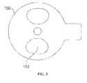
- FIG. 3is a plan view of a PCB of the motor in FIG. 2 without the components provided above the PCB.
- FIG. 2is a sectional view of a slim type vibration motor according to an embodiment of the present invention
- FIG. 3is a plan view of a PCB of the motor in FIG. 2 without the components provided above the PCB.
- a case 110includes an upper case 111 and a lower case 115 coupled together to form a predetermined space within.
- the upper case 111 and the lower case 115support both ends of a supporting shaft 120 .
- a bearing 130is inserted around the outer surface of the supporting shaft 120 , and a rotor 140 is provided to rotate around the outer surface of the bearing 130 .
- the rotor 140is provided around the outside of the bearing 130 , and has an eccentric rotor yoke 141 with a magnet 143 and a weight 145 fixed on the bottom surface of the rotor yoke 141 .
- the weight 145allows the rotor 140 to impart a large vibrating force.
- the rotor yoke 141is fixed directly to the bearing 130 , ensuring convenience in assembly.
- the upper surface of the upper case 111has a washer 180 fixed thereto.
- the washer 180prevents the rotor yoke 141 from colliding with the lower case 111 , and absorbs shock in the event that a collision occurs.
- the washer 180functions when the vibration motor is moved and the rotor 140 is moved.
- the washer 180can especially increase operational reliability of the vibration motor when the rotor 140 is subjected to shocks while rotating at high speed.
- Wound coils 160 for generating an electric field when a current is supplied thereto and rotating the rotor 140is provided below the magnet 143 .
- the magnet 143is a six-pole magnet.
- the slim type vibration motor 100increases the thickness of the wound coils 160 to increase torque output while reducing power consumption.
- a coil hole 151is formed in a portion of the PCB 150 opposite the magnet 143 , and the coil 160 is passed through the coil hole 151 and fixed on the lower case 115 .
- the coil hole 151may be formed symmetrically about the supporting shaft 120 .
- the coil 160may be firmly adhered to the bottom surface of the lower case 115 using an adhesive.
- Another methodis to use a double-sided adhesive tape to fix the coil 160 .
- the thickness of the magnet of a slim type vibration motoris 0.4-0.5 mm
- the thickness of the coilis 0.5-0.6 mm
- the thickness of the PCBis 0.15-0.20 mm.
- the coil 160 of the slim type vibration motor 100 according to the present inventionbecause it is passed through the PCB 150 and fixed to the lower case 115 , can be increased by the thickness of the PCB 150 .
- the number of wire windings of the coil 160may be increased by an amount corresponding to the thickness of the PCB 150 , increasing torque according to Equation 1 below.
- T]ZsI2Ns1 Equation 1
- the slim type vibration motor 100increases the number of windings in the coil 160 by the thickness of the PCB 150 to generate an adequate amount of torque while reducing power consumption.
- the coil 160passes through the coil hole 151 and protrudes a predetermined height from the top surface of the PCB 150 so that the number of coil 160 windings can be increased.
- the slim type vibration motor according to the present inventionpasses the coil through the PCB and fixes it on the lower case.
- an increase in the size of the slim type vibration motorcan be minimized, and the thickness of the coil can be increased by the thickness of the PCB. That is, the number of wire windings can be increased to produce an adequate amount of torque while reducing power consumption.
- the coilhas been described as being adhered to the lower case using an adhesive or double-sided tape, the coil may be attached to the lower case through an inserting structure.
- the present inventionoptimally positions the coil, so that the thickness of the vibration motor can be reduced, the electric field intensity can be increased, more torque can be generated, and power consumption can be reduced.
Landscapes
- Engineering & Computer Science (AREA)
- Power Engineering (AREA)
- Manufacturing & Machinery (AREA)
- Signal Processing (AREA)
- Physics & Mathematics (AREA)
- Electromagnetism (AREA)
- Mechanical Engineering (AREA)
- Apparatuses For Generation Of Mechanical Vibrations (AREA)
- Connection Of Motors, Electrical Generators, Mechanical Devices, And The Like (AREA)
- Windings For Motors And Generators (AREA)
Abstract
Description
T]ZsI=2Ns1 Equation 1
Claims (8)
Applications Claiming Priority (3)
| Application Number | Priority Date | Filing Date | Title |
|---|---|---|---|
| KR10-2005-0090032 | 2005-09-27 | ||
| KR1020050090032AKR100737529B1 (en) | 2005-09-27 | 2005-09-27 | Slim vibration motor |
| PCT/KR2006/003858WO2007037622A1 (en) | 2005-09-27 | 2006-09-27 | Slim type vibration motor |
Publications (2)
| Publication Number | Publication Date |
|---|---|
| US20080246356A1 US20080246356A1 (en) | 2008-10-09 |
| US7615901B2true US7615901B2 (en) | 2009-11-10 |
Family
ID=37899997
Family Applications (1)
| Application Number | Title | Priority Date | Filing Date |
|---|---|---|---|
| US12/088,214Expired - Fee RelatedUS7615901B2 (en) | 2005-09-27 | 2006-09-27 | Slim type vibration motor |
Country Status (5)
| Country | Link |
|---|---|
| US (1) | US7615901B2 (en) |
| JP (1) | JP2009510983A (en) |
| KR (1) | KR100737529B1 (en) |
| CN (1) | CN101107766B (en) |
| WO (1) | WO2007037622A1 (en) |
Cited By (4)
| Publication number | Priority date | Publication date | Assignee | Title |
|---|---|---|---|---|
| US20110187209A1 (en)* | 2010-02-01 | 2011-08-04 | Pu yong-hua | Linear vibrating motor |
| US20150288248A1 (en)* | 2014-04-04 | 2015-10-08 | Nidec Seimitsu Corporation | Vibration motor |
| US20180212487A1 (en)* | 2017-01-25 | 2018-07-26 | Shanghai Source Electrical Co., Ltd. | Magnetic balance structure and a magnetic balance linear vibration motor |
| US10862368B2 (en)* | 2016-07-19 | 2020-12-08 | Sang-eui LEE | Brushless direct current vibration motor having cogging plates for optimized vibrations |
Families Citing this family (3)
| Publication number | Priority date | Publication date | Assignee | Title |
|---|---|---|---|---|
| CN102005854B (en)* | 2010-11-02 | 2013-03-20 | 瑞声声学科技(深圳)有限公司 | Vibration motor and assembling method thereof |
| KR101309405B1 (en)* | 2012-01-20 | 2013-09-17 | 삼성전기주식회사 | Vibration motor |
| JP6470552B2 (en)* | 2014-11-19 | 2019-02-13 | 日本電産セイミツ株式会社 | Vibration motor |
Citations (8)
| Publication number | Priority date | Publication date | Assignee | Title |
|---|---|---|---|---|
| US4636677A (en)* | 1984-08-17 | 1987-01-13 | Alps Electric Co., Ltd. | Drive coil wiring structure for brushless motor |
| US5175459A (en)* | 1991-08-19 | 1992-12-29 | Motorola, Inc. | Low profile vibratory alerting device |
| US6573627B2 (en)* | 2001-06-21 | 2003-06-03 | Risun Expanse Corp. | DC brushless voice-coil vibration motor |
| US6734594B2 (en) | 2001-09-10 | 2004-05-11 | Samsung Electro-Mechanics Co., Ltd. | Vibration motor |
| US6806603B1 (en) | 2003-06-20 | 2004-10-19 | Samsung Electro-Mechanics Co., Ltd. | Flat type vibration motor |
| US6836039B2 (en) | 2002-12-30 | 2004-12-28 | Samsung Electro-Mechanics Co., Ltd. | Brushless vibration motor |
| US6998742B2 (en)* | 2002-10-28 | 2006-02-14 | Tokyo Parts Industrial Co., Ltd. | Axial-air-gap brushless vibration motor containing drive circuit |
| US7352093B2 (en) | 2003-05-13 | 2008-04-01 | Lg Innotek Co., Ltd. | Flat type vibration motor and rotor structure |
Family Cites Families (10)
| Publication number | Priority date | Publication date | Assignee | Title |
|---|---|---|---|---|
| JPS589563A (en)* | 1981-07-07 | 1983-01-19 | Mitsubishi Electric Corp | Transistor motor |
| JPH0767307A (en)* | 1993-08-31 | 1995-03-10 | Matsushita Electric Ind Co Ltd | Axial brushless motor |
| JP2002210410A (en)* | 2001-01-18 | 2002-07-30 | Tokyo Parts Ind Co Ltd | Axially gapped eccentric rotor provided with halt position holding means and flat coreless vibration motor using the eccentric rotor |
| JP3605072B2 (en)* | 2001-12-10 | 2004-12-22 | 日本電産コパル株式会社 | Brushless motor |
| JP3514750B1 (en)* | 2002-09-13 | 2004-03-31 | 東京パーツ工業株式会社 | Thin coreless motor |
| JP3568521B2 (en)* | 2002-10-28 | 2004-09-22 | 東京パーツ工業株式会社 | Axial gap type brushless vibration motor with built-in drive circuit |
| JP3894493B2 (en)* | 2003-06-24 | 2007-03-22 | 東京パーツ工業株式会社 | Eccentric rotor and axial gap type vibration motor provided with the eccentric rotor |
| JP2005051963A (en)* | 2003-07-31 | 2005-02-24 | Tokyo Parts Ind Co Ltd | Motor |
| JP3796238B2 (en)* | 2003-09-12 | 2006-07-12 | 東京パーツ工業株式会社 | An axial air gap type coreless vibration motor having the same type rotor as the mold type eccentric rotor |
| JP2005218206A (en)* | 2004-01-29 | 2005-08-11 | Tokyo Parts Ind Co Ltd | Eccentric rotor and vibration motor using the eccentric rotor |
- 2005
- 2005-09-27KRKR1020050090032Apatent/KR100737529B1/ennot_activeExpired - Fee Related
- 2006
- 2006-09-27USUS12/088,214patent/US7615901B2/ennot_activeExpired - Fee Related
- 2006-09-27CNCN2006800028053Apatent/CN101107766B/ennot_activeExpired - Fee Related
- 2006-09-27JPJP2008532171Apatent/JP2009510983A/enactivePending
- 2006-09-27WOPCT/KR2006/003858patent/WO2007037622A1/enactiveApplication Filing
Patent Citations (8)
| Publication number | Priority date | Publication date | Assignee | Title |
|---|---|---|---|---|
| US4636677A (en)* | 1984-08-17 | 1987-01-13 | Alps Electric Co., Ltd. | Drive coil wiring structure for brushless motor |
| US5175459A (en)* | 1991-08-19 | 1992-12-29 | Motorola, Inc. | Low profile vibratory alerting device |
| US6573627B2 (en)* | 2001-06-21 | 2003-06-03 | Risun Expanse Corp. | DC brushless voice-coil vibration motor |
| US6734594B2 (en) | 2001-09-10 | 2004-05-11 | Samsung Electro-Mechanics Co., Ltd. | Vibration motor |
| US6998742B2 (en)* | 2002-10-28 | 2006-02-14 | Tokyo Parts Industrial Co., Ltd. | Axial-air-gap brushless vibration motor containing drive circuit |
| US6836039B2 (en) | 2002-12-30 | 2004-12-28 | Samsung Electro-Mechanics Co., Ltd. | Brushless vibration motor |
| US7352093B2 (en) | 2003-05-13 | 2008-04-01 | Lg Innotek Co., Ltd. | Flat type vibration motor and rotor structure |
| US6806603B1 (en) | 2003-06-20 | 2004-10-19 | Samsung Electro-Mechanics Co., Ltd. | Flat type vibration motor |
Cited By (7)
| Publication number | Priority date | Publication date | Assignee | Title |
|---|---|---|---|---|
| US20110187209A1 (en)* | 2010-02-01 | 2011-08-04 | Pu yong-hua | Linear vibrating motor |
| US8552598B2 (en)* | 2010-02-01 | 2013-10-08 | Aac Acoustic Technologies (Shenzhen) Co., Ltd. | Linear vibrating motor |
| US20150288248A1 (en)* | 2014-04-04 | 2015-10-08 | Nidec Seimitsu Corporation | Vibration motor |
| US9800115B2 (en)* | 2014-04-04 | 2017-10-24 | Nidec Seimitsu Corporation | Vibration motor |
| US10862368B2 (en)* | 2016-07-19 | 2020-12-08 | Sang-eui LEE | Brushless direct current vibration motor having cogging plates for optimized vibrations |
| US20180212487A1 (en)* | 2017-01-25 | 2018-07-26 | Shanghai Source Electrical Co., Ltd. | Magnetic balance structure and a magnetic balance linear vibration motor |
| US10468928B2 (en)* | 2017-01-25 | 2019-11-05 | Shanghai Source Electrical Co., Ltd. | Magnetic balance structure and a magnetic balance linear vibration motor |
Also Published As
| Publication number | Publication date |
|---|---|
| KR100737529B1 (en) | 2007-07-10 |
| CN101107766A (en) | 2008-01-16 |
| KR20070035323A (en) | 2007-03-30 |
| JP2009510983A (en) | 2009-03-12 |
| US20080246356A1 (en) | 2008-10-09 |
| WO2007037622A1 (en) | 2007-04-05 |
| CN101107766B (en) | 2010-09-15 |
Similar Documents
| Publication | Publication Date | Title |
|---|---|---|
| US8227946B2 (en) | Flat type vibration motor | |
| US7615901B2 (en) | Slim type vibration motor | |
| US6465921B1 (en) | Assembling structure of a miniature vibration motor | |
| US7157823B2 (en) | Brushless vibration motor | |
| US6600245B1 (en) | Vibration motor | |
| US6636007B2 (en) | DC brushless vibration motor | |
| CN109565189B (en) | Brushless DC vibration motor | |
| US8076808B2 (en) | Flat type vibration motor | |
| KR100389631B1 (en) | Vibration motor | |
| US7679241B2 (en) | Vibration motor | |
| KR20050035079A (en) | Stator containing a driving circuit member and axial direction gap type brushless motor having the stator | |
| JP2004147468A (en) | Axial air-gap brushless vibrating motor incorporating drive circuit | |
| JP2004297903A (en) | Axial gap type brushless motor | |
| KR100992100B1 (en) | Rotor of Vibration Motor | |
| KR20110045821A (en) | Flat vibration motor | |
| KR100783537B1 (en) | Flat vibration motor | |
| KR20030040705A (en) | Coin-type coreless vibration motor | |
| KR101797099B1 (en) | Flat Type Vibration Motor | |
| KR101140957B1 (en) | Flat type vibration motor | |
| KR20090124363A (en) | Rotor of Vibration Motor | |
| JP2003018813A (en) | Eccentric rotor having high-density members and manufacturing method of the rotor Flat coreless vibration motor using the rotor | |
| JP2005094899A (en) | Stator containing hole sensor and drive circuit, and axial air-gap type brushless motor equipped with the stator | |
| JP2002119913A (en) | Eccentric rotor and flat vibration motor equipped with the same | |
| KR20020088440A (en) | Vibration motor |
Legal Events
| Date | Code | Title | Description |
|---|---|---|---|
| AS | Assignment | Owner name:LG INNOTEK CO., LTD, KOREA, REPUBLIC OF Free format text:ASSIGNMENT OF ASSIGNORS INTEREST;ASSIGNOR:PARK, YOUNG IL;REEL/FRAME:022424/0848 Effective date:20070622 | |
| STCF | Information on status: patent grant | Free format text:PATENTED CASE | |
| FEPP | Fee payment procedure | Free format text:PAYOR NUMBER ASSIGNED (ORIGINAL EVENT CODE: ASPN); ENTITY STATUS OF PATENT OWNER: LARGE ENTITY | |
| FEPP | Fee payment procedure | Free format text:PAYER NUMBER DE-ASSIGNED (ORIGINAL EVENT CODE: RMPN); ENTITY STATUS OF PATENT OWNER: LARGE ENTITY Free format text:PAYOR NUMBER ASSIGNED (ORIGINAL EVENT CODE: ASPN); ENTITY STATUS OF PATENT OWNER: LARGE ENTITY | |
| FPAY | Fee payment | Year of fee payment:4 | |
| AS | Assignment | Owner name:TL ELECTRONICS CO., LTD., CHINA Free format text:ASSIGNMENT OF ASSIGNORS INTEREST;ASSIGNOR:LG INNOTEK CO., LTD.;REEL/FRAME:037378/0381 Effective date:20151221 | |
| FPAY | Fee payment | Year of fee payment:8 | |
| FEPP | Fee payment procedure | Free format text:MAINTENANCE FEE REMINDER MAILED (ORIGINAL EVENT CODE: REM.); ENTITY STATUS OF PATENT OWNER: LARGE ENTITY | |
| LAPS | Lapse for failure to pay maintenance fees | Free format text:PATENT EXPIRED FOR FAILURE TO PAY MAINTENANCE FEES (ORIGINAL EVENT CODE: EXP.); ENTITY STATUS OF PATENT OWNER: LARGE ENTITY | |
| STCH | Information on status: patent discontinuation | Free format text:PATENT EXPIRED DUE TO NONPAYMENT OF MAINTENANCE FEES UNDER 37 CFR 1.362 | |
| FP | Lapsed due to failure to pay maintenance fee | Effective date:20211110 |