US7615042B2 - Transmission for a remote catheterization system - Google Patents
Transmission for a remote catheterization systemDownload PDFInfo
- Publication number
- US7615042B2 US7615042B2US10/561,147US56114705AUS7615042B2US 7615042 B2US7615042 B2US 7615042B2US 56114705 AUS56114705 AUS 56114705AUS 7615042 B2US7615042 B2US 7615042B2
- Authority
- US
- United States
- Prior art keywords
- main gear
- elongated device
- drive
- roller
- linear
- Prior art date
- Legal status (The legal status is an assumption and is not a legal conclusion. Google has not performed a legal analysis and makes no representation as to the accuracy of the status listed.)
- Expired - Lifetime, expires
Links
Images


Classifications
- A—HUMAN NECESSITIES
- A61—MEDICAL OR VETERINARY SCIENCE; HYGIENE
- A61M—DEVICES FOR INTRODUCING MEDIA INTO, OR ONTO, THE BODY; DEVICES FOR TRANSDUCING BODY MEDIA OR FOR TAKING MEDIA FROM THE BODY; DEVICES FOR PRODUCING OR ENDING SLEEP OR STUPOR
- A61M25/00—Catheters; Hollow probes
- A61M25/01—Introducing, guiding, advancing, emplacing or holding catheters
- A61M25/0105—Steering means as part of the catheter or advancing means; Markers for positioning
- A61M25/0113—Mechanical advancing means, e.g. catheter dispensers
- A—HUMAN NECESSITIES
- A61—MEDICAL OR VETERINARY SCIENCE; HYGIENE
- A61B—DIAGNOSIS; SURGERY; IDENTIFICATION
- A61B34/00—Computer-aided surgery; Manipulators or robots specially adapted for use in surgery
- A61B34/30—Surgical robots
- A61B2034/301—Surgical robots for introducing or steering flexible instruments inserted into the body, e.g. catheters or endoscopes
Definitions
- the present inventionrelates generally to invasive medical probes and methods, and specifically to intravascular catheterization and catheterization techniques.
- Cathetersare used for many medical procedures, including inserting a guide wire, delivering a stent, and delivering and inflating a balloon.
- Catheterization proceduresare very commonly performed for diagnosis and treatment of diseases of the heart and vascular system.
- the catheterization procedureis generally initiated by inserting a guide wire into a blood vessel in the patient's body.
- the guide wireis then guided to the desired location, most commonly in one of the heart vessels or elsewhere in the vascular system.
- the catheteris slid over the guide wire into the blood vessel and/or heart.
- the guide wirecan then be removed, leaving the catheter in location.
- the catheteris inserted without using a guide wire.
- the cathetermay be used to pass ancillary devices into the body, such as an angioplasty balloon, or to perform other diagnostic or therapeutic procedures.
- the physiciangenerally performs the procedure with the assistance of a fluoroscope, as is well known in the art.
- the fluoroscopeproduces a real-time image showing the continued progress of the guide wire, or the catheter, through the patient's body.
- the fluoroscopegenerates a high level of X-ray radiation, which poses a significant danger to medical personnel exposed thereto, as is well known in the art.
- the attending medical personnelIn order to provide protection from radiation exposure, the attending medical personnel generally wear a heavy, cumbersome protective lead garment which covers the entire body and neck, or use various lead shields including transparent glass face and eye shields.
- the use of fluoroscopy in the catheterization labpresents safety concerns for training, monitoring, and record keeping among the catheterization lab staff. The staff constantly monitors the radiation dosage that each member receives.
- U.S. Pat. No. 5,779,623, POSITIONER FOR MEDICAL INSTRUMENTS(1998) Bonnell, features a remote-controlled device for selectively positioning a medical instrument within a predetermined region of space.
- the remote-controlled devicehas a motor which provides mechanical energy to the remote-controlled device, a driver that is coupled to the motor and that has a predetermined relationship with the motor.
- the driverphysically engages the medical instrument and converts the mechanical energy into controlled motion of the medical instrument.
- the remote-controlled devicereceives control signals from a remote location that direct the motor to supply a predetermined amount of mechanical energy, whereby the driver, with the predetermined relationship with the motor, selectively positions the medical instrument within the region of space.
- U.S. Pat. No. 5,779,623does not provide rotational movement of the medical instrument, nor position feedback, nor a fast method for inserting and removing the instrument.
- U.S. Pat. No. 6,726,675 REMOTE CONTROL CATHETERIZATION (2004)Dalia Beyar, describes a remote control catheterization system including a propelling device, which controllably inserts a flexible, elongate probe into the body of a patient.
- a control unitin communication with the propelling device, includes user controls which are operated by a user of the system remote from the patient to control insertion of the probe into the body by the propelling device.
- the present inventionis intended to provide a transmission mechanism for a remote catheterization system, such as that provided in U.S. Pat. No. 6,726,675.
- the transmissionis a mechanical assembly that holds a slender and greatly elongated solid medical component, such as a catheterization guide wire, between two pressure rollers.
- Linear motion of the guide wireis accomplished by motorized rotation of the rollers on their axes.
- Rotational motion of the guide wireis accomplished by motorized rotation of the assembly, which holds the rollers and the guide wire, around the guide wire's linear axis. Movement combining advance and rotation can be accomplished as well.
- the guide wireIn end insertion, the guide wire is fed into the transmission along the guide wire's longitudinal axis until the desired point on the guide wire is reached.
- a slot in the transmissionenables the guide wire to be inserted directly at the desired point, with no need for feeding. The same principles apply when removing the guide wire from the transmission.
- an apparatus for imparting motion from at least one of a plurality of motion sources into linear, rotary, or combined linear and rotary motion of an elongated devicecomprising:
- the external motion sourceis a motor.
- the apparatusfurther comprises:
- the elongated deviceis a medical device.
- the elongated deviceis a guide wire.
- the elongated deviceis a catheter.
- a transmission apparatus for imparting linear, rotary, or combined linear and rotary motion to an elongated devicecomprising:
- the first drive and the second drivetransmit power to the first main gear and the second main gear respectively via drive screws.
- the first drive and the second driveare motors.
- the first main gear and the second main gearare each provided with a slot to enable lateral insertion or removal of the elongated device.
- the first drive and the second driveare provided with a position tracking mechanism so as to allow automated alignment of the slots for insertion or removal of the elongated device.
- the linear drivecomprises two geared rollers that are geared to the second main gear.
- the two geared rollersresiliently grip the elongated device, and may be separated in order to insert or remove the elongated device.
- a first position sensormeasures the position of the first drive and a second position sensor measures the position of the second drive, whereby an open control loop can be applied to the operation of the first and second drives.
- the two geared rollersare connected to a linear position sensor, whereby the actual movement of the elongated device is measured, whereby a closed control loop comprising the actual position of the elongated device from the linear position sensor and the first and second drive positions from the first and second position sensors.
- the elongated deviceis a medical device.
- the elongated deviceis a guide wire.
- the elongated deviceis a catheter.
- a transmission apparatus for imparting linear, rotary, or combined linear and rotary motion to an elongated devicecomprising:
- the first drive and the second driveare motors.
- the main gearis provided with a slot to enable lateral insertion or removal of the elongated device.
- the first drive and the second driveare provided with a position tracking mechanism so as to allow automated alignment of the slot and the linear drive for insertion or removal of the elongated device.
- the linear drivecomprises two geared rollers.
- the two geared rollersresiliently grip the elongated device, and may be separated in order to insert or remove the elongated device.
- a first position sensormeasures the position of the first drive and a second position sensor measures the position of the second drive, whereby an open control loop can be applied to the operation of the first and second drives.
- the two geared rollersare connected to a linear position sensor, whereby the actual movement of the elongated device is measured, whereby a closed control loop comprising the actual position of the elongated device from the linear position sensor and the first and second drive positions from the first and second position sensors.
- the first drivecomprises a motor that imparts rotational force to a first drive roller that both imparts rotational force to the main gear and imparts rotational force via a translation roller to a second drive roller that also imparts force to the main gear.
- the second driveis a motor that is driven by an internal source and controlled via wireless means.
- the second driveis a that is driven by power from a coil on the main gear that is in contact with brushes on the base.
- the elongated deviceis a medical device.
- the elongated deviceis a guide wire.
- the elongated deviceis a catheter.
- a method for imparting linear, rotary, or combined linear and rotary motion to an elongated devicecomprising:
- a method for imparting linear, rotary, or combined linear and rotary motion to an elongated devicecomprising:
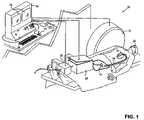
- FIG. 1is a view of a remote control catheterization system incorporating a mechanical transmission, in accordance with a preferred embodiment of the present invention.
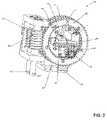
- FIG. 2is a front projection view of a mechanical transmission, in accordance with a preferred embodiment of the present invention.
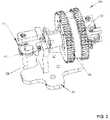
- FIG. 3is a top projection view of a mechanical transmission, in accordance with a preferred embodiment of the present invention.
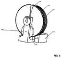
- FIG. 4is a rear projection view of a mechanical transmission, in accordance with another preferred embodiment of the present invention.
- FIG. 5is a front projection view of a mechanical transmission, in accordance with another preferred embodiment of the present invention.
- the present inventiondiscloses a transmission apparatus for imparting motion from at least one of a plurality of motion sources into linear, rotary, or combined linear and rotary motion of an elongated device.
- a preferred embodiment of the present inventionprovides a mechanical transmission for a remote control catheterization system, such as that of U.S. Pat. No. 6,726,675 REMOTE CONTROL CATHETERIZATION (2004), Dalia Beyar, which is included herein by reference.
- the innovation of the present inventionis the transmission that it provides. While the present invention is particularly suited for integration with U.S. Pat. No. 6,726,675, it can generally be used with other remote control catheterization systems for linear and rotational motion of a guide wire or catheter. Furthermore, it can be integrated into any system that incorporates user-determined motion of an elongated device along or around the device's longitudinal axis. In a preferred embodiment of the present invention, the elongated device is a guide wire, however it could equally be another type of elongated device, such as a catheter or probe.
- FIG. 1is a simplified, pictorial illustration of a remote control catheterization system 20 , in accordance with a preferred embodiment of the present invention.
- the invention of U.S. Pat. No. 6,726,675is summarized as follows:
- System 20comprises a guiding catheter (or guide wire, other elongated probe, or other elongated device) 26 , which is fed via a cannula 42 into a blood vessel 44 leading to a target location in a vessel or a heart 24 of a patient 22 .
- a guiding catheteror guide wire, other elongated probe, or other elongated device
- the catheteris fed over a guide wire, which is omitted in FIG. 1 for simplicity.
- Catheter 26is fed through a catheter propelling device 28 , and then coupled proximally with a catheter interface 30 .
- Interface 30may be used to perform various therapeutic and/or diagnostic catheter procedures, such as balloon inflation or injection of contrast media, or any other such catheter-based treatments known in the art.
- a fluoroscope 32is used to capture images showing the position of catheter 26 in the patient's body. (For simplicity, the X-ray tube associated with the fluoroscope is not shown in the figure.)
- Propelling device 28 , interface 30 and fluoroscope 32all communicate with a control unit 34 .
- the various elements of system 20relay operative information to console 34 , and receive operative instructions from the console.
- device 28relays to console 34 force measurements associated with insertion of the catheter and an indication of the distance that the catheter has traveled; interface 30 relays applicable data from the catheter regarding the therapeutic and/or diagnostic procedures being performed; and fluoroscope 32 conveys X-ray images.
- the dataare preferably displayed on console 34 via a pair of displays, monitors 36 .
- monitors 36Preferably, one of monitors 36 displays fluoroscopic images, and the other monitor displays data received from propelling device 28 and interface 30 .
- the datamay be presented using dials, meters, or any means known and used in the art.
- Medical personnel operating system 20use device 38 , preferably a keyboard, to send directional commands, for example to control table and fluoroscope motions, and to operate interface 30 and fluoroscope 32 .
- a user interface device 40preferably a handle, is moved by a user to initiate linear or rotational movement. The direction and distance of the move is relayed via circuitry to propelling device 28 . While the user of the present invention is assumed to be a medical professional, the invention can be easily adapted by one skilled in the art, for an automated user, such as a mechanical, electrical, or optical mechanism.
- console 34is preferably located outside of the catheterization room or in an area of the room that is shielded from radiation generated by the fluoroscope X-ray tube.
- the present inventionvia this usage of remote control communication with console 34 , thus furnishes the medical staff with all the relevant information, and all the relevant remote control means, to perform the catheterization operation without danger of radiation exposure.
- console 34may be in a remote location, even in a different city from the patient, and communicate with the other elements of system 20 over telecommunication channels.
- cannula 42is inserted into blood vessel 44 .
- a guide wireis threaded through cannula 42 into vessel 44 .
- catheter 26is slipped over the guide wire and guided to a desired position, for example, in one of the chambers of heart 24 or in one of the coronary arteries.
- catheter 26Once catheter 26 is in place, the guide wire may be withdrawn if desired.
- An ancillary instrument(not shown), such as an angioplasty balloon, may be passed through the catheter, into the heart or arteries.
- the guide wire, catheter and ancillary instrumentare themselves substantially similar to devices of these types known in the art.
- the mechanical transmission 100 of the present inventionforms part of propelling device 28 , converting motor motion into linear, rotational, or combined linear and rotational motion of the guide wire.
- Transmission 100can be implemented many ways, as will be clear to one skilled in the art. Herein a preferred embodiment of transmission 100 is described to illustrate one implementation.
- Transmission mechanism 100is composed of a set of rotating parts and some stationary parts that can move the guide wire when driven by two motors.
- the combined motion of the motorscauses motion of the guide wire linearly, rotationally, or both.
- the guide wireis held between two rollers and moved linearly by rotation of the rollers and rotationally by rotation of the base of the rollers.
- Transmission mechanism 100essentially consists of a turret assembly, a base to hold the turret, and two gears to pass motion from the motors to the turret.
- the turretcomprises two large (relative to the smaller gears mounted inside them) diameter gears, where first main gear 81 is attached via a cylindrical bush to base 67 in a manner that permits rotational movement of first main gear 81 and second main gear 82 is attached to first main gear 81 in a manner that permits rotational movement of part 82 independent of first main gear 81 .
- First main gear 81has teeth on its outer perimeter to accept motor force from drive screw 61 .
- Drive Screw 61is turned by drive shaft 63 , which is turned by a motor (not shown).
- An encoder or other position sensorcan be installed on the motor or the drive screw 61 .
- First main gear 81has a slot, similar to slot 73 of gear 82 , in its perimeter to facilitate insertion of the guide wire between rollers 83 and 84 from the side.
- the slotenables insertion of the guide wire at any time directly through the slot and between rollers 83 and 84 , thereby eliminating the need to insert the end of the guide wire and feed it through until reaching the desired point on the guide wire at which to apply the rollers.
- the slotenables direct removal of the guide wire instead of having to pull the entire length of the wire through the rollers.
- Second main gear 82has teeth on its outer perimeter as well as on its inner perimeter and is mounted on first main gear 81 such that it can rotate independently and coaxially to first main gear 81 .
- Second main gear 82transmits forces from drive screw 62 to roller drive gear 65 .
- Drive screw 62is turned by drive shaft 64 , which is turned by a motor (not shown).
- An encoder or other position sensorcan be installed on the motor or on drive screw 62 .
- second main gear 82has a slot 73 to facilitate the insertion of the guide wire directly into the rollers 83 and 84 from the side, thereby removing the need to feed the length of the guide wire into the rollers.
- the operatoractivates a control on console 34 .
- the systemalready knows the position of the slots from feedback from the encoders on the motors or drive screws.
- the systemcalculates the closest point where the slots can be aligned and commands the motor to move them into alignment.
- the guide wirecan then be inserted/removed between/from rollers 83 and 84 via the slots.
- Rollers 83 and 84hold the guide wire and drive it linearly, by translating mechanical energy received through the transmission from the motors.
- Drive roller 83is driven by roller gear 65 , which is driven by second main gear 82 . This motion moves the guide wire longitudinally and, according to the direction of rotation, inserts the guide wire into the patient or retracts the guide wire from the patient.
- Holder roller 84holds the guide wire against part 83 and is mounted on movable holder arm 70 in a manner that governs the pressure between holder roller 84 and drive roller 83 such that the guide wire is held firmly without slipping. In a preferred embodiment of the present invention, this is effected by spring-loading arm 70 . Holder roller 84 receives motion from drive roller 83 , thereby ensuring that holder roller 84 rotates at the same speed as drive roller 83 .
- Both drive roller 83 and holder roller 84are mounted indirectly on first main gear 81 . Therefore, when first main gear 81 rotates behind second main gear 82 , the bases of rollers ( 83 and 84 ) are rotated correspondingly, imparting rotational movement to the guide wire held by the rollers. This results in rotational guide wire motion similar to that an operator imparts with his fingers when driving the guide wire manually.
- rollers 83 and 84rotate about their axes and impart linear motion to the guide wire. This results in longitudinal guide wire motion similar to the linear movement that an operator imparts with his hand when driving the guide wire manually.
- transmission 100The primary purpose of transmission 100 is to translate motor motion to linear and/or rotational motion of the guide wire. In the preferred embodiment described here this is accomplished as follows:
- V( 82 )Vlinear ⁇ V( 81 )
- V( 82 )Vlinear ⁇ V( 81 )
- Position translation rollers 91 and 92are rollers that are free to rotate about their axes, holding the guide wire between them with sufficient pressure that longitudinal movement of the guide wire causes a corresponding rotation of the rollers.
- the rotation of the rollersis measured by an encoder, or other position sensor, connected to shaft 93 .
- Shaft 93is common for both the encoder and position translation roller 91 . Therefore the encoder measures the movement of position translation roller 91 and, thereby, the linear movement of the guide wire.
- the actual linear movement of the guide wire measured by the encoder attached to shaft 93can be compared with the motor movements measured by the encoders attached to the motors or to the drive screws 61 and 62 .
- the turretcomprises a main gear 117 mounted on base 115 and geared on its outer perimeter to accept motor force from drive rollers 119 and 112 .
- First drive roller 119is turned by motor 118 and rotates second drive roller 112 via wheel 120 .
- Main gear 117has a slot 121 in its perimeter to facilitate insertion of the guide wire between linear drive rollers 113 and 116 from the side.
- the slotenables insertion of the guide wire at any time directly through the slot and between linear drive rollers 113 and 116 , thereby eliminating the need to insert the end of the guide wire and feed it through until reaching the desired point on the guide wire at which to apply the rollers.
- the slotenables direct removal of the guide wire instead of having to pull the entire length of the wire through the rollers.
- Linear drive rollers 113 and 116hold the guide wire and drive it linearly, by translating mechanical energy received through motor 114 .
- the rollersare mounted on main gear 117 such that when main gear 117 rotates, the assembly comprising the rollers rotates with it.
- Motor 114receive its power in a manner that enables controlled transmission of power while leaving the motor free to rotate with main gear 117 .
- the motorcan be powered by a self-contained source, such as an internal battery, or through electrical circuit 111 .
- Circuit 111is an open circuit implemented as a coil on main gear 117 that is movably in contact with brushes located on base 115 .
- Control of the motorcan be implemented via a wireless means (such as infra red communication) in the case of a self-contained source or via the coil in electrical circuit 111 in the case of that implementation.
- Linear movement of the guide wireis accomplished by motor 114 rotating the rollers 113 and 116 only.
- Rotational movement of the guide wireis accomplished by motor 118 moving main gear 117 . This rotates the assembly comprising rollers 113 and 116 , thereby rotating the guide wire.
- Combined linear and rotational movement of the guide wirecan be done by combining movement of both motors, each controlled independent of the other.
- Position of the motors and of the guide wirecan be tracked by position sensors as was described earlier in this disclosure.
Landscapes
- Health & Medical Sciences (AREA)
- Life Sciences & Earth Sciences (AREA)
- Hematology (AREA)
- Animal Behavior & Ethology (AREA)
- Engineering & Computer Science (AREA)
- Anesthesiology (AREA)
- Biomedical Technology (AREA)
- Heart & Thoracic Surgery (AREA)
- Biophysics (AREA)
- Pulmonology (AREA)
- General Health & Medical Sciences (AREA)
- Public Health (AREA)
- Veterinary Medicine (AREA)
- Media Introduction/Drainage Providing Device (AREA)
- Transmission Devices (AREA)
- Fluid-Damping Devices (AREA)
- Selective Calling Equipment (AREA)
- External Artificial Organs (AREA)
Abstract
Description
- Translates motor force into linear and rotational motion of the guide wire or other slender and greatly elongated solid medical component.
- Can perform both linear and rotational motion simultaneously
- is simple and mechanically reliable
- provides two ways to mount guide wire in transmission: end insertion and side insertion
- a transmission for translating the motion to linear or rotary motion of the elongated device.
- a controller electrically connected via drive circuitry to the motor and receiving positioning commands from an individual or machine;
- a position feedback sensor measuring movement of the drive mechanism;
- wherein motion of the elongated device is controlled by a closed control loop comprising the controller driving the motor and the sensor providing feedback about the elongated device motion to the controller.
- a first main gear rotationally attached to a support and capable of being driven by a first drive;
- a second main gear coaxially and rotationally attached to the first main gear, the second main gear geared to a roller drive gear and capable of being driven by a second drive;
- a linear drive in which the elongated device may be engaged along an axis of the elongated device's rotation, the linear drive coupled to the first main gear, such that when the first main gear is rotated, the elongated device is rotated about the elongated device's axis of rotation, the linear drive being geared to the roller drive gear, such that when the second main gear is rotated the linear drive imparts linear motion to the elongated device.
- a main gear rotationally attached to a support and capable of being driven by a first drive;
- a linear drive in which the elongated device may be engaged along an axis of the elongated device's rotation, the linear drive coupled to the first main gear, such that when the first main gear is rotated, the elongated device is rotated about the elongated device's axis of rotation, the linear drive being geared to a second drive to impart linear motion to the elongated device.
- rotating a first main gear rotationally attached to a support and capable of being driven by a first drive;
- rotating a second main gear coaxially and rotationally attached to the first main gear, the second main gear geared to a roller drive gear and capable of being driven by a second drive;
- engaging the elongated device along an axis of the elongated device's rotation in a linear drive, the linear drive coupled to the first main gear, such that when the first main gear is rotated, the elongated device is rotated about the elongated device's axis of rotation, the linear drive being geared to the roller drive gear, such that when the second main gear is rotated the linear drive imparts linear motion to the elongated device.
- rotating a main gear rotationally attached to a support and capable of being driven by a first drive;
engaging the elongated device along an axis of the elongated device's rotation in a linear drive, the linear drive coupled to the main gear, such that when the main gear is rotated, the elongated device is rotated about the elongated device's axis of rotation, the linear drive being geared to a second drive, such that the linear drive imparts linear motion to the elongated device.
- rotating a main gear rotationally attached to a support and capable of being driven by a first drive;
- linear motion only: rotation of front
main gear 82 only - rotational motion only: rotation of both main gears,81 and82, in the same direction
- linear and rotational motion.
- linear motion only: rotation of front
Vlinear=V(81)+V(82)
Vrotation=V(81)
Claims (20)
Applications Claiming Priority (3)
| Application Number | Priority Date | Filing Date | Title |
|---|---|---|---|
| IL162318 | 2004-06-03 | ||
| IL162318AIL162318A (en) | 2004-06-03 | 2004-06-03 | Transmission for a remote catheterization system |
| PCT/IL2005/000497WO2005117596A2 (en) | 2004-06-03 | 2005-05-10 | Transmission for a remote catheterization system |
Publications (2)
| Publication Number | Publication Date |
|---|---|
| US20060229587A1 US20060229587A1 (en) | 2006-10-12 |
| US7615042B2true US7615042B2 (en) | 2009-11-10 |
Family
ID=35463279
Family Applications (1)
| Application Number | Title | Priority Date | Filing Date |
|---|---|---|---|
| US10/561,147Expired - LifetimeUS7615042B2 (en) | 2004-06-03 | 2005-05-10 | Transmission for a remote catheterization system |
Country Status (5)
| Country | Link |
|---|---|
| US (1) | US7615042B2 (en) |
| EP (1) | EP1755727B1 (en) |
| AT (1) | ATE540720T1 (en) |
| IL (1) | IL162318A (en) |
| WO (1) | WO2005117596A2 (en) |
Cited By (85)
| Publication number | Priority date | Publication date | Assignee | Title |
|---|---|---|---|---|
| US20070276216A1 (en)* | 2004-08-16 | 2007-11-29 | Refael Beyar | Image-Guided Navigation for Catheter-Based Interventions |
| US20080097465A1 (en)* | 2006-10-21 | 2008-04-24 | Aaron Rollins | Guidewire Manipulation Device |
| US20090105645A1 (en)* | 2007-08-21 | 2009-04-23 | Brian Kidd | Apparatus for selectively rotating and/or advancing an elongate device |
| US20090131955A1 (en)* | 2005-09-29 | 2009-05-21 | Corindus Ltd. | Methods and apparatuses for treatment of hollow organs |
| US20090326449A1 (en)* | 2008-06-25 | 2009-12-31 | National Taiwan University | Control apparatus of catheter feeder |
| US20100204613A1 (en)* | 2009-02-10 | 2010-08-12 | Aaron Rollins | Method and apparatus for manipulating a surgical guidewire |
| US20110144658A1 (en)* | 2008-08-29 | 2011-06-16 | Corindus Inc. | Catheter simulation and assistance system |
| US20110238082A1 (en)* | 2008-12-12 | 2011-09-29 | Corindus Inc. | Remote catheter procedure system |
| US20120220830A1 (en)* | 2009-06-24 | 2012-08-30 | Imperial InnovationsLimited | Joint arrangement |
| US8257302B2 (en) | 2005-05-10 | 2012-09-04 | Corindus, Inc. | User interface for remote control catheterization |
| US20130172713A1 (en)* | 2011-12-29 | 2013-07-04 | Mark B. Kirschenman | Drive assembly for use in a robotic control and guidance system |
| US8480618B2 (en) | 2008-05-06 | 2013-07-09 | Corindus Inc. | Catheter system |
| US8694157B2 (en) | 2008-08-29 | 2014-04-08 | Corindus, Inc. | Catheter control system and graphical user interface |
| US8790297B2 (en) | 2009-03-18 | 2014-07-29 | Corindus, Inc. | Remote catheter system with steerable catheter |
| US20140276936A1 (en)* | 2013-03-15 | 2014-09-18 | Hansen Medical, Inc. | Active drive mechanism for simultaneous rotation and translation |
| US20140343527A1 (en)* | 2013-05-17 | 2014-11-20 | Covidien Lp | Torque apparatus for use with a guidewire |
| US9220568B2 (en) | 2009-10-12 | 2015-12-29 | Corindus Inc. | Catheter system with percutaneous device movement algorithm |
| US9326822B2 (en) | 2013-03-14 | 2016-05-03 | Hansen Medical, Inc. | Active drives for robotic catheter manipulators |
| US9408669B2 (en) | 2013-03-15 | 2016-08-09 | Hansen Medical, Inc. | Active drive mechanism with finite range of motion |
| US9833293B2 (en) | 2010-09-17 | 2017-12-05 | Corindus, Inc. | Robotic catheter system |
| US9962229B2 (en) | 2009-10-12 | 2018-05-08 | Corindus, Inc. | System and method for navigating a guide wire |
| US9974678B2 (en) | 2014-03-10 | 2018-05-22 | Cook Medical Technologies Llc | Wire collection device with varying collection diameter |
| US9974677B2 (en) | 2013-08-20 | 2018-05-22 | Cook Medical Technologies Llc | Wire collection device for stent delivery system |
| US9974676B2 (en) | 2013-08-09 | 2018-05-22 | Cook Medical Technologies Llc | Wire collection device with geared advantage |
| US10046140B2 (en)* | 2014-04-21 | 2018-08-14 | Hansen Medical, Inc. | Devices, systems, and methods for controlling active drive systems |
| US10213264B2 (en) | 2013-03-14 | 2019-02-26 | Auris Health, Inc. | Catheter tension sensing |
| US10219874B2 (en) | 2013-10-24 | 2019-03-05 | Auris Health, Inc. | Instrument device manipulator with tension sensing apparatus |
| US10226263B2 (en) | 2015-12-23 | 2019-03-12 | Incuvate, Llc | Aspiration monitoring system and method |
| CN109999320A (en)* | 2019-04-30 | 2019-07-12 | 清华大学 | Catheter propelling device and method for blood vessel intervention operation |
| US10398518B2 (en) | 2014-07-01 | 2019-09-03 | Auris Health, Inc. | Articulating flexible endoscopic tool with roll capabilities |
| US10454347B2 (en) | 2016-04-29 | 2019-10-22 | Auris Health, Inc. | Compact height torque sensing articulation axis assembly |
| US10470830B2 (en) | 2017-12-11 | 2019-11-12 | Auris Health, Inc. | Systems and methods for instrument based insertion architectures |
| US10478595B2 (en) | 2013-03-07 | 2019-11-19 | Auris Health, Inc. | Infinitely rotatable tool with finite rotating drive shafts |
| US10493239B2 (en) | 2013-03-14 | 2019-12-03 | Auris Health, Inc. | Torque-based catheter articulation |
| US10543047B2 (en) | 2013-03-15 | 2020-01-28 | Auris Health, Inc. | Remote catheter manipulator |
| US10543048B2 (en) | 2016-12-28 | 2020-01-28 | Auris Health, Inc. | Flexible instrument insertion using an adaptive insertion force threshold |
| US10556092B2 (en) | 2013-03-14 | 2020-02-11 | Auris Health, Inc. | Active drives for robotic catheter manipulators |
| US10561440B2 (en) | 2015-09-03 | 2020-02-18 | Vesatek, Llc | Systems and methods for manipulating medical devices |
| US10569052B2 (en) | 2014-05-15 | 2020-02-25 | Auris Health, Inc. | Anti-buckling mechanisms for catheters |
| US10631949B2 (en) | 2015-09-09 | 2020-04-28 | Auris Health, Inc. | Instrument device manipulator with back-mounted tool attachment mechanism |
| US10682189B2 (en) | 2016-08-31 | 2020-06-16 | Auris Health, Inc. | Length conservative surgical instrument |
| US10695536B2 (en) | 2001-02-15 | 2020-06-30 | Auris Health, Inc. | Catheter driver system |
| US10820952B2 (en) | 2013-03-15 | 2020-11-03 | Auris Heath, Inc. | Rotational support for an elongate member |
| US10820947B2 (en) | 2018-09-28 | 2020-11-03 | Auris Health, Inc. | Devices, systems, and methods for manually and robotically driving medical instruments |
| US10820954B2 (en) | 2018-06-27 | 2020-11-03 | Auris Health, Inc. | Alignment and attachment systems for medical instruments |
| US10888386B2 (en) | 2018-01-17 | 2021-01-12 | Auris Health, Inc. | Surgical robotics systems with improved robotic arms |
| US11026758B2 (en) | 2017-06-28 | 2021-06-08 | Auris Health, Inc. | Medical robotics systems implementing axis constraints during actuation of one or more motorized joints |
| US11076924B2 (en) | 2017-12-29 | 2021-08-03 | The Board Of Regents Of The University Of Texas System | Steerable surgical robotic system |
| US11147637B2 (en) | 2012-05-25 | 2021-10-19 | Auris Health, Inc. | Low friction instrument driver interface for robotic systems |
| US20210367478A1 (en)* | 2013-06-26 | 2021-11-25 | Corindus, Inc. | Differential Drive |
| US11213363B2 (en) | 2013-03-14 | 2022-01-04 | Auris Health, Inc. | Catheter tension sensing |
| US11213362B2 (en) | 2019-11-28 | 2022-01-04 | Microbot Medical Ltd. | Device for automatically inserting and manipulating a medical tool into and within a bodily lumen |
| US11241559B2 (en) | 2016-08-29 | 2022-02-08 | Auris Health, Inc. | Active drive for guidewire manipulation |
| US11246672B2 (en) | 2019-08-15 | 2022-02-15 | Auris Health, Inc. | Axial motion drive devices, systems, and methods for a robotic medical system |
| US11266424B2 (en) | 2017-06-20 | 2022-03-08 | Siemens Healthcare Gmbh | Autonomous catheterization assembly |
| US11285300B2 (en) | 2015-08-12 | 2022-03-29 | Vesatek, Llc | System and method for manipulating an elongate medical device |
| US11382650B2 (en) | 2015-10-30 | 2022-07-12 | Auris Health, Inc. | Object capture with a basket |
| US11439419B2 (en) | 2019-12-31 | 2022-09-13 | Auris Health, Inc. | Advanced basket drive mode |
| US11510736B2 (en) | 2017-12-14 | 2022-11-29 | Auris Health, Inc. | System and method for estimating instrument location |
| US11534249B2 (en) | 2015-10-30 | 2022-12-27 | Auris Health, Inc. | Process for percutaneous operations |
| US11571229B2 (en) | 2015-10-30 | 2023-02-07 | Auris Health, Inc. | Basket apparatus |
| US11638618B2 (en) | 2019-03-22 | 2023-05-02 | Auris Health, Inc. | Systems and methods for aligning inputs on medical instruments |
| US11653945B2 (en) | 2007-02-05 | 2023-05-23 | Walk Vascular, Llc | Thrombectomy apparatus and method |
| US11678905B2 (en) | 2018-07-19 | 2023-06-20 | Walk Vascular, Llc | Systems and methods for removal of blood and thrombotic material |
| US11737845B2 (en) | 2019-09-30 | 2023-08-29 | Auris Inc. | Medical instrument with a capstan |
| US11771309B2 (en) | 2016-12-28 | 2023-10-03 | Auris Health, Inc. | Detecting endolumenal buckling of flexible instruments |
| US11896330B2 (en) | 2019-08-15 | 2024-02-13 | Auris Health, Inc. | Robotic medical system having multiple medical instruments |
| US11918314B2 (en) | 2009-10-12 | 2024-03-05 | Corindus, Inc. | System and method for navigating a guide wire |
| US11925770B2 (en) | 2018-05-17 | 2024-03-12 | Route 92 Medical, Inc. | Aspiration catheter systems and methods of use |
| US11950872B2 (en) | 2019-12-31 | 2024-04-09 | Auris Health, Inc. | Dynamic pulley system |
| US12115320B2 (en) | 2013-12-23 | 2024-10-15 | Route 92 Medical, Inc. | Methods and systems for treatment of acute ischemic stroke |
| US12144940B2 (en) | 2020-10-09 | 2024-11-19 | Route 92 Medical, Inc. | Aspiration catheter systems and methods of use |
| US12150659B2 (en) | 2014-05-19 | 2024-11-26 | Walk Vascular, Llc | Systems and methods for removal of blood and thrombotic material |
| US12171444B2 (en) | 2021-02-15 | 2024-12-24 | Walk Vascular, Llc | Systems and methods for removal of blood and thrombotic material |
| US12194247B2 (en) | 2017-01-20 | 2025-01-14 | Route 92 Medical, Inc. | Single operator intracranial medical device delivery systems and methods of use |
| US12213688B2 (en) | 2015-07-24 | 2025-02-04 | Route 92 Medical, Inc. | Anchoring delivery system and methods |
| US12232838B2 (en) | 2021-08-12 | 2025-02-25 | Imperative Care, Inc. | Method of robotically performing a neurovascular procedure |
| US12262911B2 (en) | 2011-08-05 | 2025-04-01 | Route 92 Medical, Inc. | Methods and systems for treatment of acute ischemic stroke |
| US12274458B2 (en) | 2021-02-15 | 2025-04-15 | Walk Vascular, Llc | Systems and methods for removal of blood and thrombotic material |
| US12329406B2 (en) | 2008-10-13 | 2025-06-17 | Walk Vascular, Llc | Assisted aspiration catheter system |
| US12329397B2 (en) | 2022-08-02 | 2025-06-17 | Imperative Care, Inc. | Fluidics management system |
| US12377206B2 (en) | 2023-05-17 | 2025-08-05 | Imperative Care, Inc. | Fluidics control system for multi catheter stack |
| US12419703B2 (en) | 2022-08-01 | 2025-09-23 | Imperative Care, Inc. | Robotic drive system for achieving supra-aortic access |
| US12433702B2 (en) | 2022-12-01 | 2025-10-07 | Imperative Care, Inc. | Telescoping drive table |
| US12440289B2 (en) | 2022-12-01 | 2025-10-14 | Imperative Care, Inc. | Method of priming an interventional device assembly |
Families Citing this family (44)
| Publication number | Priority date | Publication date | Assignee | Title |
|---|---|---|---|---|
| US10863945B2 (en) | 2004-05-28 | 2020-12-15 | St. Jude Medical, Atrial Fibrillation Division, Inc. | Robotic surgical system with contact sensing feature |
| US10258285B2 (en) | 2004-05-28 | 2019-04-16 | St. Jude Medical, Atrial Fibrillation Division, Inc. | Robotic surgical system and method for automated creation of ablation lesions |
| US7632265B2 (en) | 2004-05-28 | 2009-12-15 | St. Jude Medical, Atrial Fibrillation Division, Inc. | Radio frequency ablation servo catheter and method |
| US8528565B2 (en) | 2004-05-28 | 2013-09-10 | St. Jude Medical, Atrial Fibrillation Division, Inc. | Robotic surgical system and method for automated therapy delivery |
| US8755864B2 (en) | 2004-05-28 | 2014-06-17 | St. Jude Medical, Atrial Fibrillation Division, Inc. | Robotic surgical system and method for diagnostic data mapping |
| US7974674B2 (en) | 2004-05-28 | 2011-07-05 | St. Jude Medical, Atrial Fibrillation Division, Inc. | Robotic surgical system and method for surface modeling |
| US9782130B2 (en) | 2004-05-28 | 2017-10-10 | St. Jude Medical, Atrial Fibrillation Division, Inc. | Robotic surgical system |
| US8155910B2 (en) | 2005-05-27 | 2012-04-10 | St. Jude Medical, Atrial Fibrillation Divison, Inc. | Robotically controlled catheter and method of its calibration |
| EP1907041B1 (en)* | 2005-07-11 | 2019-02-20 | Catheter Precision, Inc. | Remotely controlled catheter insertion system |
| WO2007080783A1 (en)* | 2006-01-13 | 2007-07-19 | Olympus Medical Systems Corp. | Rotary self-running endoscope system, program, and method of driving rotary self-running endoscope system |
| US20080249536A1 (en)* | 2007-02-15 | 2008-10-09 | Hansen Medical, Inc. | Interface assembly for controlling orientation of robotically controlled medical instrument |
| WO2009092059A2 (en) | 2008-01-16 | 2009-07-23 | Catheter Robotics, Inc. | Remotely controlled catheter insertion system |
| WO2010138499A1 (en)* | 2009-05-25 | 2010-12-02 | Stereotaxis, Inc. | Remote manipulator device |
| US9005217B2 (en)* | 2009-08-12 | 2015-04-14 | Biosense Webster, Inc. | Robotic drive for catheter |
| US20120071752A1 (en) | 2010-09-17 | 2012-03-22 | Sewell Christopher M | User interface and method for operating a robotic medical system |
| US9694158B2 (en)* | 2011-10-21 | 2017-07-04 | Ahmad Mohamad Slim | Torque for incrementally advancing a catheter during right heart catheterization |
| US20140066900A1 (en)* | 2012-09-06 | 2014-03-06 | Corindus, Inc. | System for guide catheter control |
| FR2999939B1 (en) | 2012-12-21 | 2015-01-16 | Robocath | CATHETERISM SYSTEM TRAINING MODULE |
| CN103157170B (en)* | 2013-02-25 | 2014-12-03 | 中国科学院自动化研究所 | Blood vessel interventional operation conduit or guide wire control device based on two-point clamping |
| CN103083783B (en)* | 2013-02-25 | 2014-07-23 | 中国科学院自动化研究所 | Clamping-based catheter or clamping-based guide wire operating device for vessel interventional operation |
| CN103083784B (en)* | 2013-02-25 | 2014-09-17 | 中国科学院自动化研究所 | Catheter or guide wire operating device for vessel interventional operation |
| US9533121B2 (en) | 2013-02-26 | 2017-01-03 | Catheter Precision, Inc. | Components and methods for accommodating guidewire catheters on a catheter controller system |
| FR3002852B1 (en) | 2013-03-07 | 2016-04-01 | Robocath | MEDICAL MEMBER TRAINING MODULE EXTENDED |
| US9993614B2 (en) | 2013-08-27 | 2018-06-12 | Catheter Precision, Inc. | Components for multiple axis control of a catheter in a catheter positioning system |
| US9724493B2 (en) | 2013-08-27 | 2017-08-08 | Catheter Precision, Inc. | Components and methods for balancing a catheter controller system with a counterweight |
| US9999751B2 (en) | 2013-09-06 | 2018-06-19 | Catheter Precision, Inc. | Adjustable nose cone for a catheter positioning system |
| US9750577B2 (en) | 2013-09-06 | 2017-09-05 | Catheter Precision, Inc. | Single hand operated remote controller for remote catheter positioning system |
| US9795764B2 (en) | 2013-09-27 | 2017-10-24 | Catheter Precision, Inc. | Remote catheter positioning system with hoop drive assembly |
| US9700698B2 (en) | 2013-09-27 | 2017-07-11 | Catheter Precision, Inc. | Components and methods for a catheter positioning system with a spreader and track |
| US10549071B2 (en)* | 2013-10-15 | 2020-02-04 | Corindus, Inc. | Guide catheter control flexible track |
| US9205229B2 (en)* | 2013-10-24 | 2015-12-08 | Avent, Inc. | Catheter advancement device |
| US10588809B2 (en)* | 2014-01-06 | 2020-03-17 | Biosense Webster (Israel) Ltd. | Cable arranger |
| FR3022788B1 (en)* | 2014-06-27 | 2022-04-08 | Robocath | ROBOTIZED SYSTEM FOR ARTERIOGRAPHY, ROBOT AND ELONGATED FLEXIBLE ORGAN FOR SUCH A SYSTEM |
| US10238845B2 (en) | 2014-09-19 | 2019-03-26 | Acclarent, Inc. | Balloon catheter assembly |
| WO2018176457A1 (en)* | 2017-04-01 | 2018-10-04 | 中国科学院深圳先进技术研究院 | Catheter twisting device for vessel interventional surgery robot |
| CN107550570B (en)* | 2017-07-06 | 2018-11-27 | 北京理工大学 | A kind of intervention operation robot guidewire controller and its control method |
| CN108096684B (en)* | 2017-11-28 | 2020-11-03 | 合肥美亚光电技术股份有限公司 | Drive device |
| EP3682933B1 (en)* | 2018-02-07 | 2022-06-29 | Terumo Kabushiki Kaisha | Medical assistance device |
| NL1043050B1 (en)* | 2018-10-23 | 2020-06-02 | Soteria Medical B V | Device for moving and rotating an elongated body such as a catheter under remote control |
| CN113082463A (en)* | 2021-04-14 | 2021-07-09 | 王利 | Rotary pushing device and interventional operation robot |
| DE102021205547A1 (en) | 2021-05-31 | 2022-12-01 | Fraunhofer-Gesellschaft zur Förderung der angewandten Forschung eingetragener Verein | Clamp actuator, moving mechanism and method for moving an elongate object |
| CN113729801A (en)* | 2021-09-13 | 2021-12-03 | 科亚医疗科技股份有限公司 | Delivery device, delivery system and interventional instrument |
| JP2025502033A (en) | 2022-01-10 | 2025-01-24 | ジフィーステント ピーティーワイ リミテッド | Stent insertion device and method |
| KR102767146B1 (en) | 2022-02-23 | 2025-02-14 | 주식회사 페라자 | Vascular intervention device and drum assembly for vascular intervention device |
Citations (8)
| Publication number | Priority date | Publication date | Assignee | Title |
|---|---|---|---|---|
| EP0331944A1 (en) | 1988-03-07 | 1989-09-13 | Combustion Engineering, Inc. | Inspection probe manipulator |
| US5377678A (en) | 1991-09-03 | 1995-01-03 | General Electric Company | Tracking system to follow the position and orientation of a device with radiofrequency fields |
| US5492131A (en) | 1994-09-06 | 1996-02-20 | Guided Medical Systems, Inc. | Servo-catheter |
| EP0970663A1 (en) | 1998-07-10 | 2000-01-12 | Mitsubishi Denki Kabushiki Kaisha | Master/slave system for the manipulation of tubular medical tools |
| US6171234B1 (en)* | 1998-09-25 | 2001-01-09 | Scimed Life Systems, Inc. | Imaging gore loading tool |
| US20030176770A1 (en)* | 2000-03-16 | 2003-09-18 | Merril Gregory L. | System and method for controlling force applied to and manipulation of medical instruments |
| US6726675B1 (en)* | 1998-03-11 | 2004-04-27 | Navicath Ltd. | Remote control catheterization |
| EP1442720A1 (en) | 2003-01-31 | 2004-08-04 | Tre Esse Progettazione Biomedica S.r.l | Apparatus for the maneuvering of flexible catheters in the human cardiovascular system |
Family Cites Families (2)
| Publication number | Priority date | Publication date | Assignee | Title |
|---|---|---|---|---|
| US5779623A (en) | 1993-10-08 | 1998-07-14 | Leonard Medical, Inc. | Positioner for medical instruments |
| EP1115327A4 (en) | 1998-08-07 | 2007-06-20 | Stereotaxis Inc | Method and apparatus for magnetically controlling catheters in body lumens and cavities |
- 2004
- 2004-06-03ILIL162318Apatent/IL162318A/enactiveIP Right Grant
- 2005
- 2005-05-10ATAT05738429Tpatent/ATE540720T1/enactive
- 2005-05-10WOPCT/IL2005/000497patent/WO2005117596A2/ennot_activeApplication Discontinuation
- 2005-05-10USUS10/561,147patent/US7615042B2/ennot_activeExpired - Lifetime
- 2005-05-10EPEP05738429Apatent/EP1755727B1/ennot_activeExpired - Lifetime
Patent Citations (9)
| Publication number | Priority date | Publication date | Assignee | Title |
|---|---|---|---|---|
| EP0331944A1 (en) | 1988-03-07 | 1989-09-13 | Combustion Engineering, Inc. | Inspection probe manipulator |
| US5377678A (en) | 1991-09-03 | 1995-01-03 | General Electric Company | Tracking system to follow the position and orientation of a device with radiofrequency fields |
| US5492131A (en) | 1994-09-06 | 1996-02-20 | Guided Medical Systems, Inc. | Servo-catheter |
| US6726675B1 (en)* | 1998-03-11 | 2004-04-27 | Navicath Ltd. | Remote control catheterization |
| EP0970663A1 (en) | 1998-07-10 | 2000-01-12 | Mitsubishi Denki Kabushiki Kaisha | Master/slave system for the manipulation of tubular medical tools |
| US6171234B1 (en)* | 1998-09-25 | 2001-01-09 | Scimed Life Systems, Inc. | Imaging gore loading tool |
| US20030176770A1 (en)* | 2000-03-16 | 2003-09-18 | Merril Gregory L. | System and method for controlling force applied to and manipulation of medical instruments |
| EP1442720A1 (en) | 2003-01-31 | 2004-08-04 | Tre Esse Progettazione Biomedica S.r.l | Apparatus for the maneuvering of flexible catheters in the human cardiovascular system |
| US20040254566A1 (en)* | 2003-01-31 | 2004-12-16 | Gianni Plicchi | Apparatus for the maneuvering of flexible catheters in the human cardiovascular system |
Non-Patent Citations (3)
| Title |
|---|
| PCT Written Opinion of the International Searching Authority for Application Number PCT/IL05/00497, dated May 19, 2006, 3 pages. |
| Supplementary Partial European Search Report for Application Number EP 05 73 8429, dated Feb. 20, 2008, 4 pages. |
| WIPO PCT International Search Report for Application Number PCT/IL05/00497, dated Dec. 15, 2005, 2 pages. |
Cited By (156)
| Publication number | Priority date | Publication date | Assignee | Title |
|---|---|---|---|---|
| US10695536B2 (en) | 2001-02-15 | 2020-06-30 | Auris Health, Inc. | Catheter driver system |
| US20070276216A1 (en)* | 2004-08-16 | 2007-11-29 | Refael Beyar | Image-Guided Navigation for Catheter-Based Interventions |
| US8600477B2 (en) | 2004-08-16 | 2013-12-03 | Corinduc, Inc. | Image-guided navigation for catheter-based interventions |
| US8257302B2 (en) | 2005-05-10 | 2012-09-04 | Corindus, Inc. | User interface for remote control catheterization |
| US20090131955A1 (en)* | 2005-09-29 | 2009-05-21 | Corindus Ltd. | Methods and apparatuses for treatment of hollow organs |
| US9119942B1 (en) | 2006-10-21 | 2015-09-01 | Vesatek, Llc | Guidewire manipulation device |
| US9050438B2 (en) | 2006-10-21 | 2015-06-09 | Vesatek, Llc | Guidewire manipulation device |
| US20080097465A1 (en)* | 2006-10-21 | 2008-04-24 | Aaron Rollins | Guidewire Manipulation Device |
| US11534582B2 (en) | 2006-10-21 | 2022-12-27 | Vesatek, Llc | Guidewire manipulation device |
| US12369940B2 (en) | 2007-02-05 | 2025-07-29 | Walk Vascular, Llc | Thrombectomy apparatus and method |
| US11653945B2 (en) | 2007-02-05 | 2023-05-23 | Walk Vascular, Llc | Thrombectomy apparatus and method |
| US7998020B2 (en) | 2007-08-21 | 2011-08-16 | Stereotaxis, Inc. | Apparatus for selectively rotating and/or advancing an elongate device |
| US20090105645A1 (en)* | 2007-08-21 | 2009-04-23 | Brian Kidd | Apparatus for selectively rotating and/or advancing an elongate device |
| US10987491B2 (en) | 2008-05-06 | 2021-04-27 | Corindus, Inc. | Robotic catheter system |
| US11717645B2 (en) | 2008-05-06 | 2023-08-08 | Corindus, Inc. | Robotic catheter system |
| US8828021B2 (en) | 2008-05-06 | 2014-09-09 | Corindus, Inc. | Catheter system |
| US8480618B2 (en) | 2008-05-06 | 2013-07-09 | Corindus Inc. | Catheter system |
| US9402977B2 (en) | 2008-05-06 | 2016-08-02 | Corindus Inc. | Catheter system |
| US9095681B2 (en) | 2008-05-06 | 2015-08-04 | Corindus Inc. | Catheter system |
| US10342953B2 (en) | 2008-05-06 | 2019-07-09 | Corindus, Inc. | Robotic catheter system |
| US9623209B2 (en) | 2008-05-06 | 2017-04-18 | Corindus, Inc. | Robotic catheter system |
| US9168356B2 (en) | 2008-05-06 | 2015-10-27 | Corindus Inc. | Robotic catheter system |
| US20090326449A1 (en)* | 2008-06-25 | 2009-12-31 | National Taiwan University | Control apparatus of catheter feeder |
| US8694157B2 (en) | 2008-08-29 | 2014-04-08 | Corindus, Inc. | Catheter control system and graphical user interface |
| US20110144658A1 (en)* | 2008-08-29 | 2011-06-16 | Corindus Inc. | Catheter simulation and assistance system |
| US12329406B2 (en) | 2008-10-13 | 2025-06-17 | Walk Vascular, Llc | Assisted aspiration catheter system |
| US20110238082A1 (en)* | 2008-12-12 | 2011-09-29 | Corindus Inc. | Remote catheter procedure system |
| US9545497B2 (en) | 2008-12-12 | 2017-01-17 | Corindus, Inc. | Remote catheter procedure system |
| US10561821B2 (en) | 2008-12-12 | 2020-02-18 | Corindus, Inc. | Remote catheter procedure system |
| US12171955B2 (en) | 2008-12-12 | 2024-12-24 | Siemens Healthineers Endovascular Robotics Inc | Remote catheter procedure system |
| US8926529B2 (en)* | 2009-02-10 | 2015-01-06 | Vesatek, Llc | Method and apparatus for manipulating a surgical guidewire |
| US9539416B2 (en) | 2009-02-10 | 2017-01-10 | Vesatek, Llc | System and method for traversing an arterial occlusion |
| US10682501B2 (en) | 2009-02-10 | 2020-06-16 | Vesatek, Llc | System and method for traversing an arterial occlusion |
| US9119941B2 (en) | 2009-02-10 | 2015-09-01 | Vesatek, Llc | Method and apparatus for manipulating a surgical guidewire |
| US20100204613A1 (en)* | 2009-02-10 | 2010-08-12 | Aaron Rollins | Method and apparatus for manipulating a surgical guidewire |
| US11660424B2 (en) | 2009-02-10 | 2023-05-30 | Vesatek, Llc | System and method for traversing an arterial occlusion |
| US8790297B2 (en) | 2009-03-18 | 2014-07-29 | Corindus, Inc. | Remote catheter system with steerable catheter |
| US8974375B2 (en)* | 2009-06-24 | 2015-03-10 | Imperial Innovations Ltd. | Joint arrangement |
| US20120220830A1 (en)* | 2009-06-24 | 2012-08-30 | Imperial InnovationsLimited | Joint arrangement |
| US9220568B2 (en) | 2009-10-12 | 2015-12-29 | Corindus Inc. | Catheter system with percutaneous device movement algorithm |
| US9962229B2 (en) | 2009-10-12 | 2018-05-08 | Corindus, Inc. | System and method for navigating a guide wire |
| US11696808B2 (en) | 2009-10-12 | 2023-07-11 | Corindus, Inc. | System and method for navigating a guide wire |
| US11918314B2 (en) | 2009-10-12 | 2024-03-05 | Corindus, Inc. | System and method for navigating a guide wire |
| US10881474B2 (en) | 2009-10-12 | 2021-01-05 | Corindus, Inc. | System and method for navigating a guide wire |
| US9833293B2 (en) | 2010-09-17 | 2017-12-05 | Corindus, Inc. | Robotic catheter system |
| US12343036B2 (en) | 2011-08-05 | 2025-07-01 | Route 92 Medical, Inc. | Methods and systems for treatment of acute ischemic stroke |
| US12262911B2 (en) | 2011-08-05 | 2025-04-01 | Route 92 Medical, Inc. | Methods and systems for treatment of acute ischemic stroke |
| US20130172713A1 (en)* | 2011-12-29 | 2013-07-04 | Mark B. Kirschenman | Drive assembly for use in a robotic control and guidance system |
| US9402555B2 (en)* | 2011-12-29 | 2016-08-02 | St. Jude Medical, Atrial Fibrillation Division, Inc. | Drive assembly for use in a robotic control and guidance system |
| US11147637B2 (en) | 2012-05-25 | 2021-10-19 | Auris Health, Inc. | Low friction instrument driver interface for robotic systems |
| US10478595B2 (en) | 2013-03-07 | 2019-11-19 | Auris Health, Inc. | Infinitely rotatable tool with finite rotating drive shafts |
| US10493239B2 (en) | 2013-03-14 | 2019-12-03 | Auris Health, Inc. | Torque-based catheter articulation |
| US12420063B2 (en) | 2013-03-14 | 2025-09-23 | Auris Health, Inc. | Torque-based catheter articulation |
| US11517717B2 (en) | 2013-03-14 | 2022-12-06 | Auris Health, Inc. | Active drives for robotic catheter manipulators |
| US10556092B2 (en) | 2013-03-14 | 2020-02-11 | Auris Health, Inc. | Active drives for robotic catheter manipulators |
| US11779414B2 (en) | 2013-03-14 | 2023-10-10 | Auris Health, Inc. | Active drive for robotic catheter manipulators |
| US10687903B2 (en) | 2013-03-14 | 2020-06-23 | Auris Health, Inc. | Active drive for robotic catheter manipulators |
| US9326822B2 (en) | 2013-03-14 | 2016-05-03 | Hansen Medical, Inc. | Active drives for robotic catheter manipulators |
| US10213264B2 (en) | 2013-03-14 | 2019-02-26 | Auris Health, Inc. | Catheter tension sensing |
| US11213363B2 (en) | 2013-03-14 | 2022-01-04 | Auris Health, Inc. | Catheter tension sensing |
| US11452844B2 (en) | 2013-03-14 | 2022-09-27 | Auris Health, Inc. | Torque-based catheter articulation |
| US10792112B2 (en) | 2013-03-15 | 2020-10-06 | Auris Health, Inc. | Active drive mechanism with finite range of motion |
| US12114943B2 (en) | 2013-03-15 | 2024-10-15 | Auris Health, Inc. | Remote catheter manipulator |
| US11660153B2 (en) | 2013-03-15 | 2023-05-30 | Auris Health, Inc. | Active drive mechanism with finite range of motion |
| US20140276936A1 (en)* | 2013-03-15 | 2014-09-18 | Hansen Medical, Inc. | Active drive mechanism for simultaneous rotation and translation |
| US10543047B2 (en) | 2013-03-15 | 2020-01-28 | Auris Health, Inc. | Remote catheter manipulator |
| US10820952B2 (en) | 2013-03-15 | 2020-11-03 | Auris Heath, Inc. | Rotational support for an elongate member |
| US10524867B2 (en) | 2013-03-15 | 2020-01-07 | Auris Health, Inc. | Active drive mechanism for simultaneous rotation and translation |
| US11376085B2 (en) | 2013-03-15 | 2022-07-05 | Auris Health, Inc. | Remote catheter manipulator |
| US11504195B2 (en) | 2013-03-15 | 2022-11-22 | Auris Health, Inc. | Active drive mechanism for simultaneous rotation and translation |
| US9408669B2 (en) | 2013-03-15 | 2016-08-09 | Hansen Medical, Inc. | Active drive mechanism with finite range of motion |
| US20140343527A1 (en)* | 2013-05-17 | 2014-11-20 | Covidien Lp | Torque apparatus for use with a guidewire |
| US9814864B2 (en)* | 2013-05-17 | 2017-11-14 | Covidien Lp | Torque apparatus for use with a guidewire |
| US12136867B2 (en)* | 2013-06-26 | 2024-11-05 | Corindus, Inc. | Differential drive |
| US20210367478A1 (en)* | 2013-06-26 | 2021-11-25 | Corindus, Inc. | Differential Drive |
| US9974676B2 (en) | 2013-08-09 | 2018-05-22 | Cook Medical Technologies Llc | Wire collection device with geared advantage |
| US9974677B2 (en) | 2013-08-20 | 2018-05-22 | Cook Medical Technologies Llc | Wire collection device for stent delivery system |
| US10219874B2 (en) | 2013-10-24 | 2019-03-05 | Auris Health, Inc. | Instrument device manipulator with tension sensing apparatus |
| US12115320B2 (en) | 2013-12-23 | 2024-10-15 | Route 92 Medical, Inc. | Methods and systems for treatment of acute ischemic stroke |
| US12343480B2 (en) | 2013-12-23 | 2025-07-01 | Route 92 Medical, Inc. | Methods and systems for treatment of acute ischemic stroke |
| US9974678B2 (en) | 2014-03-10 | 2018-05-22 | Cook Medical Technologies Llc | Wire collection device with varying collection diameter |
| US10046140B2 (en)* | 2014-04-21 | 2018-08-14 | Hansen Medical, Inc. | Devices, systems, and methods for controlling active drive systems |
| US11278703B2 (en) | 2014-04-21 | 2022-03-22 | Auris Health, Inc. | Devices, systems, and methods for controlling active drive systems |
| US10569052B2 (en) | 2014-05-15 | 2020-02-25 | Auris Health, Inc. | Anti-buckling mechanisms for catheters |
| US11690977B2 (en) | 2014-05-15 | 2023-07-04 | Auris Health, Inc. | Anti-buckling mechanisms for catheters |
| US12343483B2 (en) | 2014-05-15 | 2025-07-01 | Auris Health, Inc. | Anti-buckling mechanisms for catheters |
| US12156665B2 (en) | 2014-05-19 | 2024-12-03 | Walk Vascular, Llc | Systems and methods for removal of blood and thrombotic material |
| US12150659B2 (en) | 2014-05-19 | 2024-11-26 | Walk Vascular, Llc | Systems and methods for removal of blood and thrombotic material |
| US10398518B2 (en) | 2014-07-01 | 2019-09-03 | Auris Health, Inc. | Articulating flexible endoscopic tool with roll capabilities |
| US11350998B2 (en) | 2014-07-01 | 2022-06-07 | Auris Health, Inc. | Medical instrument having translatable spool |
| US12213688B2 (en) | 2015-07-24 | 2025-02-04 | Route 92 Medical, Inc. | Anchoring delivery system and methods |
| US11285300B2 (en) | 2015-08-12 | 2022-03-29 | Vesatek, Llc | System and method for manipulating an elongate medical device |
| US11672561B2 (en) | 2015-09-03 | 2023-06-13 | Walk Vascular, Llc | Systems and methods for manipulating medical devices |
| US10561440B2 (en) | 2015-09-03 | 2020-02-18 | Vesatek, Llc | Systems and methods for manipulating medical devices |
| US10631949B2 (en) | 2015-09-09 | 2020-04-28 | Auris Health, Inc. | Instrument device manipulator with back-mounted tool attachment mechanism |
| US11771521B2 (en) | 2015-09-09 | 2023-10-03 | Auris Health, Inc. | Instrument device manipulator with roll mechanism |
| US10786329B2 (en) | 2015-09-09 | 2020-09-29 | Auris Health, Inc. | Instrument device manipulator with roll mechanism |
| US11559360B2 (en) | 2015-10-30 | 2023-01-24 | Auris Health, Inc. | Object removal through a percutaneous suction tube |
| US11534249B2 (en) | 2015-10-30 | 2022-12-27 | Auris Health, Inc. | Process for percutaneous operations |
| US12433696B2 (en) | 2015-10-30 | 2025-10-07 | Auris Health, Inc. | Tool positioning for medical instruments with working channels |
| US11382650B2 (en) | 2015-10-30 | 2022-07-12 | Auris Health, Inc. | Object capture with a basket |
| US11571229B2 (en) | 2015-10-30 | 2023-02-07 | Auris Health, Inc. | Basket apparatus |
| US10226263B2 (en) | 2015-12-23 | 2019-03-12 | Incuvate, Llc | Aspiration monitoring system and method |
| US11051832B2 (en) | 2015-12-23 | 2021-07-06 | Incuvate, Llc | Aspiration monitoring system and method |
| US11771445B2 (en) | 2015-12-23 | 2023-10-03 | Incuvate, Llc | Aspiration monitoring system and method |
| US10454347B2 (en) | 2016-04-29 | 2019-10-22 | Auris Health, Inc. | Compact height torque sensing articulation axis assembly |
| US10903725B2 (en) | 2016-04-29 | 2021-01-26 | Auris Health, Inc. | Compact height torque sensing articulation axis assembly |
| US11241559B2 (en) | 2016-08-29 | 2022-02-08 | Auris Health, Inc. | Active drive for guidewire manipulation |
| US10682189B2 (en) | 2016-08-31 | 2020-06-16 | Auris Health, Inc. | Length conservative surgical instrument |
| US11564759B2 (en) | 2016-08-31 | 2023-01-31 | Auris Health, Inc. | Length conservative surgical instrument |
| US10543048B2 (en) | 2016-12-28 | 2020-01-28 | Auris Health, Inc. | Flexible instrument insertion using an adaptive insertion force threshold |
| US11771309B2 (en) | 2016-12-28 | 2023-10-03 | Auris Health, Inc. | Detecting endolumenal buckling of flexible instruments |
| US12194247B2 (en) | 2017-01-20 | 2025-01-14 | Route 92 Medical, Inc. | Single operator intracranial medical device delivery systems and methods of use |
| US11266424B2 (en) | 2017-06-20 | 2022-03-08 | Siemens Healthcare Gmbh | Autonomous catheterization assembly |
| US11026758B2 (en) | 2017-06-28 | 2021-06-08 | Auris Health, Inc. | Medical robotics systems implementing axis constraints during actuation of one or more motorized joints |
| US11832907B2 (en) | 2017-06-28 | 2023-12-05 | Auris Health, Inc. | Medical robotics systems implementing axis constraints during actuation of one or more motorized joints |
| US10470830B2 (en) | 2017-12-11 | 2019-11-12 | Auris Health, Inc. | Systems and methods for instrument based insertion architectures |
| US10779898B2 (en) | 2017-12-11 | 2020-09-22 | Auris Health, Inc. | Systems and methods for instrument based insertion architectures |
| US11839439B2 (en) | 2017-12-11 | 2023-12-12 | Auris Health, Inc. | Systems and methods for instrument based insertion architectures |
| US11510736B2 (en) | 2017-12-14 | 2022-11-29 | Auris Health, Inc. | System and method for estimating instrument location |
| US11076924B2 (en) | 2017-12-29 | 2021-08-03 | The Board Of Regents Of The University Of Texas System | Steerable surgical robotic system |
| US10888386B2 (en) | 2018-01-17 | 2021-01-12 | Auris Health, Inc. | Surgical robotics systems with improved robotic arms |
| US12329477B2 (en) | 2018-01-17 | 2025-06-17 | Auris Health, Inc. | Surgical robotics systems with improved robotic arms |
| US12383702B2 (en) | 2018-05-17 | 2025-08-12 | Route 92 Medical, Inc. | Aspiration catheter systems and methods of use |
| US11925770B2 (en) | 2018-05-17 | 2024-03-12 | Route 92 Medical, Inc. | Aspiration catheter systems and methods of use |
| US10820954B2 (en) | 2018-06-27 | 2020-11-03 | Auris Health, Inc. | Alignment and attachment systems for medical instruments |
| US12364557B2 (en) | 2018-06-27 | 2025-07-22 | Auris Health, Inc. | Alignment and attachment systems for medical instruments |
| US11678905B2 (en) | 2018-07-19 | 2023-06-20 | Walk Vascular, Llc | Systems and methods for removal of blood and thrombotic material |
| US10820947B2 (en) | 2018-09-28 | 2020-11-03 | Auris Health, Inc. | Devices, systems, and methods for manually and robotically driving medical instruments |
| US11864842B2 (en) | 2018-09-28 | 2024-01-09 | Auris Health, Inc. | Devices, systems, and methods for manually and robotically driving medical instruments |
| US11638618B2 (en) | 2019-03-22 | 2023-05-02 | Auris Health, Inc. | Systems and methods for aligning inputs on medical instruments |
| CN109999320B (en)* | 2019-04-30 | 2020-12-29 | 清华大学 | Catheter pusher device and method for vascular interventional procedures |
| CN109999320A (en)* | 2019-04-30 | 2019-07-12 | 清华大学 | Catheter propelling device and method for blood vessel intervention operation |
| US11272995B2 (en) | 2019-08-15 | 2022-03-15 | Auris Health, Inc. | Axial motion drive devices, systems, and methods for a robotic medical system |
| US11246672B2 (en) | 2019-08-15 | 2022-02-15 | Auris Health, Inc. | Axial motion drive devices, systems, and methods for a robotic medical system |
| US11896330B2 (en) | 2019-08-15 | 2024-02-13 | Auris Health, Inc. | Robotic medical system having multiple medical instruments |
| US11737845B2 (en) | 2019-09-30 | 2023-08-29 | Auris Inc. | Medical instrument with a capstan |
| US12102290B2 (en) | 2019-11-28 | 2024-10-01 | Microbot Medical Ltd. | Device for automatically inserting and manipulating a medical tool into and within a bodily lumen |
| US12369777B2 (en) | 2019-11-28 | 2025-07-29 | Microbot Medical Ltd. | Modular robotic system for driving movement of surgical tools |
| US11291515B2 (en) | 2019-11-28 | 2022-04-05 | Microbot Medical Ltd. | Device for automatically inserting and manipulating a medical tool into and within a bodily lumen |
| US11213362B2 (en) | 2019-11-28 | 2022-01-04 | Microbot Medical Ltd. | Device for automatically inserting and manipulating a medical tool into and within a bodily lumen |
| US11241291B2 (en) | 2019-11-28 | 2022-02-08 | Microbot Medical Ltd. | Modular robotic system for driving movement of surgical tools |
| US11950872B2 (en) | 2019-12-31 | 2024-04-09 | Auris Health, Inc. | Dynamic pulley system |
| US12318102B2 (en) | 2019-12-31 | 2025-06-03 | Auris Health, Inc. | Advanced basket drive mode |
| US11439419B2 (en) | 2019-12-31 | 2022-09-13 | Auris Health, Inc. | Advanced basket drive mode |
| US12144940B2 (en) | 2020-10-09 | 2024-11-19 | Route 92 Medical, Inc. | Aspiration catheter systems and methods of use |
| US12274458B2 (en) | 2021-02-15 | 2025-04-15 | Walk Vascular, Llc | Systems and methods for removal of blood and thrombotic material |
| US12171445B2 (en) | 2021-02-15 | 2024-12-24 | Walk Vascular, Llc | Systems and methods for removal of blood and thrombotic material |
| US12171444B2 (en) | 2021-02-15 | 2024-12-24 | Walk Vascular, Llc | Systems and methods for removal of blood and thrombotic material |
| US12232838B2 (en) | 2021-08-12 | 2025-02-25 | Imperative Care, Inc. | Method of robotically performing a neurovascular procedure |
| US12376928B2 (en) | 2021-08-12 | 2025-08-05 | Imperative Care, Inc. | Catheter drive system for supra-aortic access |
| US12419703B2 (en) | 2022-08-01 | 2025-09-23 | Imperative Care, Inc. | Robotic drive system for achieving supra-aortic access |
| US12329397B2 (en) | 2022-08-02 | 2025-06-17 | Imperative Care, Inc. | Fluidics management system |
| US12433702B2 (en) | 2022-12-01 | 2025-10-07 | Imperative Care, Inc. | Telescoping drive table |
| US12440289B2 (en) | 2022-12-01 | 2025-10-14 | Imperative Care, Inc. | Method of priming an interventional device assembly |
| US12377206B2 (en) | 2023-05-17 | 2025-08-05 | Imperative Care, Inc. | Fluidics control system for multi catheter stack |
Also Published As
| Publication number | Publication date |
|---|---|
| WO2005117596A3 (en) | 2006-07-06 |
| US20060229587A1 (en) | 2006-10-12 |
| ATE540720T1 (en) | 2012-01-15 |
| IL162318A0 (en) | 2005-11-20 |
| EP1755727A2 (en) | 2007-02-28 |
| EP1755727A4 (en) | 2008-03-19 |
| WO2005117596A2 (en) | 2005-12-15 |
| EP1755727B1 (en) | 2012-01-11 |
| IL162318A (en) | 2011-07-31 |
Similar Documents
| Publication | Publication Date | Title |
|---|---|---|
| US7615042B2 (en) | Transmission for a remote catheterization system | |
| US6726675B1 (en) | Remote control catheterization | |
| US20240138938A1 (en) | Systems and methods for instrument based insertion architectures | |
| CN112353496B (en) | A flexible endoscope control robot | |
| US20240415372A1 (en) | Device for automatically inserting and manipulating a medical tool into and within a bodily lumen | |
| US11751956B2 (en) | Automated insertion device | |
| US20040254566A1 (en) | Apparatus for the maneuvering of flexible catheters in the human cardiovascular system | |
| AU2018290831A1 (en) | Instrument insertion compensation | |
| US20060146010A1 (en) | Computer assisted manipulation of catheters and guide wires | |
| CN101991901A (en) | Robotic drive for catheter | |
| CN118574556A (en) | Steerable sheath and adjustable scope attachment | |
| WO2022249012A1 (en) | Deflectable catheter with localization sensor | |
| CN215458616U (en) | Surgical robot system | |
| CN114831733A (en) | Surgical robot system | |
| CN119655896B (en) | A robot system for ERCP and its surgical treatment | |
| CN117796912B (en) | Vascular intervention guide wire conveying mechanism and robot | |
| CN116269791B (en) | Angiography interventional operation system convenient to disinfect | |
| CN116763451A (en) | Interventional operation robot |
Legal Events
| Date | Code | Title | Description |
|---|---|---|---|
| AS | Assignment | Owner name:NAVICATH LTD., ISRAEL Free format text:ASSIGNMENT OF ASSIGNORS INTEREST;ASSIGNORS:BEYAR, RAFAEL;WENDEROW, TAL;LINDER, DORON;AND OTHERS;REEL/FRAME:020549/0849;SIGNING DATES FROM 20080214 TO 20080221 | |
| AS | Assignment | Owner name:CORINDUS LTD., ISRAEL Free format text:ASSIGNMENT OF ASSIGNORS INTEREST;ASSIGNOR:NAVICATH, LTD.;REEL/FRAME:020563/0033 Effective date:20080213 | |
| STCF | Information on status: patent grant | Free format text:PATENTED CASE | |
| AS | Assignment | Owner name:CORINDUS INC.,MASSACHUSETTS Free format text:ASSIGNMENT OF ASSIGNORS INTEREST;ASSIGNOR:CORINDUS LTD.;REEL/FRAME:024252/0131 Effective date:20100407 Owner name:CORINDUS INC., MASSACHUSETTS Free format text:ASSIGNMENT OF ASSIGNORS INTEREST;ASSIGNOR:CORINDUS LTD.;REEL/FRAME:024252/0131 Effective date:20100407 | |
| AS | Assignment | Owner name:CORINDUS LTD,ISRAEL Free format text:CHANGE OF NAME;ASSIGNOR:NAVICATH LTD;REEL/FRAME:024305/0920 Effective date:20051122 Owner name:CORINDUS LTD, ISRAEL Free format text:CHANGE OF NAME;ASSIGNOR:NAVICATH LTD;REEL/FRAME:024305/0920 Effective date:20051122 | |
| FEPP | Fee payment procedure | Free format text:PAT HOLDER NO LONGER CLAIMS SMALL ENTITY STATUS, ENTITY STATUS SET TO UNDISCOUNTED (ORIGINAL EVENT CODE: STOL); ENTITY STATUS OF PATENT OWNER: LARGE ENTITY | |
| FEPP | Fee payment procedure | Free format text:PAYOR NUMBER ASSIGNED (ORIGINAL EVENT CODE: ASPN); ENTITY STATUS OF PATENT OWNER: LARGE ENTITY | |
| FPAY | Fee payment | Year of fee payment:4 | |
| FPAY | Fee payment | Year of fee payment:8 | |
| AS | Assignment | Owner name:CORINDUS, INC., MASSACHUSETTS Free format text:CORRECTIVE ASSIGNMENT TO CORRECT THE ASSIGNEE NAME PREVIOUSLY RECORDED AT REEL: 024252 FRAME: 0131. ASSIGNOR(S) HEREBY CONFIRMS THE ASSIGNMENT;ASSIGNOR:CORINDUS LTD.;REEL/FRAME:044035/0591 Effective date:20100407 | |
| AS | Assignment | Owner name:CORINDUS, INC., MASSACHUSETTS Free format text:CHANGE OF ADDRESS;ASSIGNOR:CORINDUS, INC.;REEL/FRAME:054548/0382 Effective date:20201130 | |
| MAFP | Maintenance fee payment | Free format text:PAYMENT OF MAINTENANCE FEE, 12TH YEAR, LARGE ENTITY (ORIGINAL EVENT CODE: M1553); ENTITY STATUS OF PATENT OWNER: LARGE ENTITY Year of fee payment:12 | |
| AS | Assignment | Owner name:SIEMENS HEALTHINEERS ENDOVASCULAR ROBOTICS, INC., MASSACHUSETTS Free format text:CHANGE OF NAME;ASSIGNOR:CORINDUS, INC.;REEL/FRAME:069333/0219 Effective date:20241018 |