US7615031B2 - Gas inflation/evacuation system incorporating a multiple element valved guidewire assembly having an occlusive device - Google Patents
Gas inflation/evacuation system incorporating a multiple element valved guidewire assembly having an occlusive deviceDownload PDFInfo
- Publication number
- US7615031B2 US7615031B2US11/217,546US21754605AUS7615031B2US 7615031 B2US7615031 B2US 7615031B2US 21754605 AUS21754605 AUS 21754605AUS 7615031 B2US7615031 B2US 7615031B2
- Authority
- US
- United States
- Prior art keywords
- inflation
- evacuation
- guidewire
- hemostatic
- valve
- Prior art date
- Legal status (The legal status is an assumption and is not a legal conclusion. Google has not performed a legal analysis and makes no representation as to the accuracy of the status listed.)
- Expired - Fee Related
Links
Images


Classifications
- A—HUMAN NECESSITIES
- A61—MEDICAL OR VETERINARY SCIENCE; HYGIENE
- A61M—DEVICES FOR INTRODUCING MEDIA INTO, OR ONTO, THE BODY; DEVICES FOR TRANSDUCING BODY MEDIA OR FOR TAKING MEDIA FROM THE BODY; DEVICES FOR PRODUCING OR ENDING SLEEP OR STUPOR
- A61M25/00—Catheters; Hollow probes
- A61M25/10—Balloon catheters
- A61M25/1018—Balloon inflating or inflation-control devices
- A61M25/10181—Means for forcing inflation fluid into the balloon
- A61M25/10182—Injector syringes
- A—HUMAN NECESSITIES
- A61—MEDICAL OR VETERINARY SCIENCE; HYGIENE
- A61M—DEVICES FOR INTRODUCING MEDIA INTO, OR ONTO, THE BODY; DEVICES FOR TRANSDUCING BODY MEDIA OR FOR TAKING MEDIA FROM THE BODY; DEVICES FOR PRODUCING OR ENDING SLEEP OR STUPOR
- A61M25/00—Catheters; Hollow probes
- A61M25/10—Balloon catheters
- A61M25/1018—Balloon inflating or inflation-control devices
- A61M25/10184—Means for controlling or monitoring inflation or deflation
- A61M25/10185—Valves
- A—HUMAN NECESSITIES
- A61—MEDICAL OR VETERINARY SCIENCE; HYGIENE
- A61M—DEVICES FOR INTRODUCING MEDIA INTO, OR ONTO, THE BODY; DEVICES FOR TRANSDUCING BODY MEDIA OR FOR TAKING MEDIA FROM THE BODY; DEVICES FOR PRODUCING OR ENDING SLEEP OR STUPOR
- A61M25/00—Catheters; Hollow probes
- A61M25/10—Balloon catheters
- A61M25/1018—Balloon inflating or inflation-control devices
- A61M25/10184—Means for controlling or monitoring inflation or deflation
- A61M25/10187—Indicators for the level of inflation or deflation
Definitions
- the present inventionrelates generally to the field of vascular medical devices. More specifically, the present invention relates to a gas inflation/evacuation system incorporating a multiple element valved guidewire assembly having an occlusive device for selectively, rapidly and repeatedly inflating and deflating an occlusive balloon and for sealing the proximal end of a guidewire tube during a vascular procedure where the invention is incorporated for unencumbered hubless use as a guidewire with inflated occlusive balloon without any protruding features upon which thrombectomy catheters or other devices may align for thrombectomy or other procedures.
- Arterial diseaseinvolves damage that happens to the arteries in the body. Diseased arteries can become plugged with thrombus, plaque, or grumous material that may ultimately lead to a condition known as ischemia. Ischemia refers to a substantial reduction or loss of blood flow to the heart muscle or any other tissue that is being supplied by the artery and can lead to permanent damage of the affected region. While arterial disease is most commonly associated with the formation of hard plaque and coronary artery disease in the heart, similar damage can happen to many other vessels in the body, such as the peripheral vessels, cerebral vessels, due to the buildup of hard plaque or softer thrombus or grumous material within the lumen of an artery or vein.
- vascular medical devices and procedureshave been developed to treat diseased vessels.
- the current standard proceduresinclude bypass surgery (where a new blood vessel is grafted around a narrowed or blocked artery) and several different types of nonsurgical interventional vascular medical procedures, including angioplasty (where a balloon on a catheter is inflated inside a narrowed or blocked portion of an artery in an attempt to push back plaque or thrombotic material), stenting (where a metal mesh tube is expanded against a narrowed or blocked portion of an artery to hold back plaque or thrombotic material), and debulking techniques in the form of atherectomy (where some type of high speed or high power mechanism is used to dislodge hardened plaque) or thrombectomy (where some type of mechanism or infused fluid is used to dislodge grumous or thrombotic material).
- atherectomywhere some type of high speed or high power mechanism is used to dislodge hardened plaque
- thrombectomywhere some type of mechanism or infused fluid is used to
- a very flexible guidewireis routed through the patient's vascular system to a desired treatment location and then a catheter that includes a device on the distal end appropriate for the given procedure is tracked along the guidewire to the treatment location.
- interventional vascular proceduresavoid many of the complications involved in surgery, there is a possibility of complications if some of the plaque, thrombus or other material breaks free and flows downstream in the artery or other vessel, potentially causing a stroke, a myocardial infarction (heart attack), or other tissue death.
- One solution to this potential complicationis to use some kind of occlusive device to block or screen the blood flowing downstream of the treatment location. Examples of catheter arrangements that use a pair of balloons as occlusive devices to create an isolated space in the blood vessel are described in U.S. Pat. Nos. 4,573,966, 4,636,195, 5,059,178, 5,320,604, 5,833,644, 5,925,016, 6,022,336 and 6,176,844.
- an occlusive deviceas part of a vascular procedure is becoming more common in debulking procedures performed on heart bypass vessels.
- Most heart bypass vesselsare harvested and transplanted from the saphenous vein located along the inside of the patient's leg.
- the saphenous veinis a long straight vein that has a capacity more than adequate to support the blood flow needs of the heart. Once transplanted, the saphenous vein is subject to a buildup of plaque or thrombotic materials in the grafted arterial lumen.
- the standard interventional vascular treatments for debulkingare only moderately successful when employed to treat saphenous vein coronary bypass grafts.
- the complication rate for a standard balloon angioplasty procedure in a saphenous vein coronary bypass graftis higher than in a native vessel with the complications including embolization, “no-reflow” phenomena, and procedural related myocardial infarction.
- Atherectomy methodsincluding directional, rotational, and laser devices are also associated with a high degree of embolization resulting in a greater likelihood of infarction.
- the use of stents for saphenous vein coronary bypass graftshas produced mixed results. Stents provide for less restenosis, but they do not eliminate the risk of embolization and infarction incurred by standard balloon angioplasty.
- embolic protection methodsutilizing a protective device distal to the lesion have been developed.
- the protective deviceis typically a filter or a balloon.
- Use of a protective device in conjunction with an atherectomy or thrombectomy deviceis intended to prevent emboli from migrating beyond the protective device and to allow the embolic particles to be removed, thereby subsequently reducing the risk of myocardial infarction.
- the occlusive deviceis a balloon, the balloon is inserted and inflated at a point distal to the treatment site or lesion site. Therapy is then performed at the treatment site and the balloon acts to block all blood flow which prevents emboli from traveling beyond the balloon.
- U.S. Pat. No. 5,843,022uses a balloon to occlude the vessel distal to a lesion or blockage site. The occlusion is treated with a high pressure water jet, and the fluid and entrained emboli are subsequently removed via an extraction tube.
- U.S. Pat. No. 6,135,991describes the use of a balloon to occlude the vessel allowing blood flow and pressure to prevent the migration of emboli proximally from the treatment device.
- 5,908,405describes an arrangement with a removable balloon member that can be repeatedly inserted into and withdrawn from a guidewire.
- U.S. Pat. No. 5,776,100describes a guidewire with an occlusive balloon adhesively bonded to the distal end with an adapter on the proximal end to provide inflation fluid for the occlusive balloon.
- filter arrangementsWhile a filter arrangement is theoretically a better solution than an occlusive device, in practice, such filter arrangements often become plugged, effectively turning the filter into an occlusive device.
- the filter arrangementsalso are mechanically and operationally more complicated than an occlusive balloon device in terms of deployment and extraction.
- a liquid fluidsuch as saline or saline mixed with a radiopaque marker for fluoroscopic visualization (i.e., contrast) as the inflation medium.
- a liquid fluid medium for expanding vascular balloonshas been preferred because the expansion characteristics of a liquid are more uniform and predictable, and because a liquid medium is easier to work with and more familiar to the doctors.
- high pressure requirementsup to 20 atmospheres necessitate that the inflation fluid be an incompressible fluid for safety reasons.
- liquid fluidsdo not lend themselves to rapid deflation of an occlusive balloon because of the high resistance to movement of the liquid in a long small diameter tube.
- the balloon catheterIn the context of angioplasty procedures, the balloon catheter has a much larger lumen than a guidewire. Consequently, rapid deflation is possible.
- liquid filled occlusive balloonstypically cannot be deflated in less than a minute and, depending upon the length of the guidewire, can take up to several minutes to deflate. Consequently, it is not practical to shorten the period of total blockage of a vessel by repeatedly deflating and then re-inflating a liquid filled occlusive balloon at the end of a guidewire.
- Gas-filled balloonshave been used for intra-aortic occlusive devices where rapid inflation and deflation of the occlusive device is required. Examples of such intra-aortic occlusive devices are shown in U.S. Pat. Nos. 4,646,719, 4,733,652, 5,865,721, 6,146,372, 6,245,008 and 6,241,706. While effective for use as an intra-aortic occlusive device, these occlusive devices are not designed for use as a guidewire as there is no ability to track a catheter over the intra-aortic occlusive device.
- the gas-filled occlusive balloonis used for distal protection to minimize the risk of embolization while treating a blocked saphenous vein coronary bypass graft.
- the occlusive balloonretains emboli dislodged by the atherectomy treatment process until such time as the emboli can be aspirated from the vessel. No specific apparatus are shown or described for how the gas is to be introduced into the device or how the occlusive balloon is deflated.
- occlusive devicesAlthough the use of occlusive devices has become more common for distal embolization protection in vascular procedures, particularly for treating a blocked saphenous vein coronary bypass graft, all of the existing approaches have significant drawbacks that can limit their effectiveness. Liquid filled occlusive balloons can remain in place too long and take too long to deflate, increasing the risk of damages downstream of the occlusion. Occlusive filters are designed to address this problem, but suffer from blockage problems and can be complicated to deploy and retrieve and may allow small embolic particles to migrate downstream.
- Existing gas-filled occlusive balloonssolve some of the problems of liquid filled occlusive balloons, but typically have utilized complicated valve and connection arrangements. It would be desirable to provide for an occlusive device that was effective, simple, quick to deploy and deflate, and that could overcome the limitations of the existing approaches.
- the gas inflation/evacuation system incorporating a multiple element valved guidewire assembly having an occlusive deviceincludes a manifold assembly removably connectible to a multiple element valved guidewire assembly having an occlusive device, and in addition thereto includes syringe means operated in cooperation with the manifold assembly for selectively evacuating the multiple element valved guidewire assembly and syringe means operated in cooperation with the manifold assembly for introducing a biocompatible gas under pressure into the multiple element valved guidewire assembly to selectively inflate the occlusive device, such as an occlusive balloon, a plurality of times.
- the multiple element valved guidewire assemblyis inserted and maneuvered within the manifold assembly to position a controllable valve therewithin for inflational and deflational control of the occlusive balloon.
- the multiple element valved guidewire assemblycan be removed from influence of the manifold assembly subsequent to occlusive balloon inflation to serve as a stand-alone guidewire while providing occlusive protection within a blood vessel.
- An embodiment set forth hereincomprises a manifold assembly removably connectible to the multiple element valved guidewire assembly.
- the multiple element valved guidewire assemblyincludes a braided polyimide guidewire tube which defines a lumen, where the distal end of the braided polyimide guidewire tube includes an occlusive balloon, inflation orifices, a flexible distally located tip and a proximal end which includes an internally located seal.
- a one-piece flexible sealing rodhaving a reduced radius support extension extending therefrom, such being a part of the multiple element valved guidewire assembly and being slidably accommodated by the braided polyimide guidewire tube.
- the sealing rodis intimately and slidingly accommodated by the seal internal to the proximal end of the braided polyimide guidewire tube to either seal or unseal the lumen leading to the occlusive balloon when inflating or deflating the occlusive balloon.
- Such an arrangementcomprises a valve at the proximal end of the braided polyimide guidewire tube incorporating interaction of a portion of the multiple element valved guidewire assembly sealing rod.
- the reduced radius support extensionextends along the lumen of the braided polyimide guidewire tube to add a degree of stiffness to the braided polyimide guidewire tube, thereby adding to the pushability of the multiple element valved guidewire assembly through the vasculature.
- the manifold assemblyremovably receives the multiple element valved guidewire assembly.
- Multiple resilient sealsare incorporated within the manifold assembly to seal against the elements of the multiple element valved guidewire assembly and to seal about the needles of the evacuation and inflation syringes.
- the valve of the multiple element valved guidewire assemblyis accommodated and sealed within the manifold assembly and opened or closed during phases of inflation and deflation in coordinated operation of the evacuation and inflation syringes.
- Operation of the inventioninvolves placement of the multiple element valved guidewire assembly into the vasculature to position a deflated occlusive balloon beyond a buildup of thrombus, plague, lesions or other foreign material buildup followed by the inflation of the occlusive balloon therein and then by removal of the manifold assembly from the multiple element valved guidewire assembly, thereby leaving in place a guidewire tube having an inflated occlusive balloon and a guidewire tube over which thrombectomy catheters or other devices may track for the purpose of thrombectomy or other procedures.
- an advantage of the present inventionis that the occlusive device can be repeatably inflated and deflated a plurality of times during a vascular procedure where the proximal end of the guidewire tube is alternately free of mechanical connections and obstructions and, therefore, the guidewire tube can function as a conventional exchange guidewire for one or more over-the-wire catheters.
- the guidewire tubecan be shorter in length for use with rapid exchange catheter systems.
- the present inventionenables repeated and quick inflation and deflation which allows an operator to deploy the gas-filled occlusive device numerous times during a procedure for shorter periods of time, thereby reducing the risk of potential damage to downstream tissue.
- the gas inflation/evacuation system incorporating a multiple element valved guidewire assembly having an occlusive deviceconstitutes a handheld apparatus.
- the sealing rodcan be repositioned to open the valve to quickly deflate the occlusive device and after a determined period can be repositioned to repeat the inflation procedure again. Multiple inflations, evacuations and deflations can be performed as required.
- One significant aspect and feature of the present inventionis the provision of a multiple element valved guidewire, a manifold assembly, an evacuation syringe and an inflation syringe.
- Another significant aspect and feature of the present inventionis a removably attached manifold assembly which is accommodated by a multiple element valved guidewire assembly.
- Another significant aspect and feature of the present inventionis the provision for repeatable inflation and deflation of an occlusive balloon multiple times.
- Another significant aspect and feature of the present inventionis the use of a multiple element valved guidewire assembly which, subsequent to inflation of an occlusive balloon, can removed from influence of a manifold assembly to serve as a guidewire for accommodation of various devices.
- Another significant aspect and feature of the present inventionis a positionable valve in a multiple element valved guidewire assembly incorporated for selective supplying of inflational medium from an inflation syringe and for selective pressurization of various components of the invention or for selective evacuation thereof by the use of an evacuation syringe.
- Another significant aspect and feature of the present inventionis a multiple element valved guidewire assembly having structure including a sealing rod which interacts with a seal located proximally in a guidewire tube to constitute a valve where the closing or opening of the valve is accomplished by longitudinal movement of the sealing rod.
- Yet another significant aspect and feature of the present inventionis a guidewire tube and a sealing rod which together serve as a guidewire.
- Another significant aspect and feature of the present inventionis the incorporation of an evacuation syringe which cooperatively interacts to evacuate a multiple element valved guidewire assembly and a manifold assembly.
- Another significant aspect and feature of the present inventionis the incorporation of an inflation syringe which cooperatively interacts to pressurize a guidewire tube in order to inflate an occlusive balloon.
- Another significant aspect and feature of the present inventionis the use of a sealing rod having a support extension extending therefrom into a braided polyimide guidewire tube, whereby the support extension lends support to the braided polyimide guidewire tube and enhances pushability and deliverability of the braided polyimide guidewire tube through the vasculature.
- Another significant aspect and feature of the present inventionis the incorporation of a check valve in an evacuation syringe to prevent air injection.
- Another significant aspect and feature of the present inventionis the incorporation of a check valve in an inflation syringe to prevent air injection.
- Still another significant aspect and feature of the present inventionis the use of self and automatic sealing resilient seals or hemostatic valves in sealing relationships with elongated elements of a multiple element valved guidewire assembly passing therethrough.
- Another significant aspect and feature of the present inventionis a balloon on a commonly used and sized guidewire tube which gives the physician many options in using such a device to control the environment within a blood vessel while other procedures can take place more safely and effectively. Furthermore, having the device sealable or hubless facilitates complete freedom for use as a primary guidewire with the option of inflating an occlusive balloon for containment or mechanical usage.
- Another significant aspect and feature of the present inventionis a hubless guidewire tube which is provided with an occlusive balloon that can be used as a distal protection device.
- Another significant aspect and feature of the present inventionis a hubless guidewire tube having an occlusive balloon, the hubless guidewire tube with occlusive balloon being useful during embolectomy.
- FIG. 1Another significant aspect and feature of the present invention is a hubless guidewire tube having an occlusive balloon, the hubless guidewire tube with occlusive balloon being useful in conjunction with an ablative device to remove clots, thrombus, plaque and the like from blood vessel walls.
- FIG. 1Another significant aspect and feature of the present invention is a hubless guidewire tube having an occlusive balloon that can be inflated and used as a positioning tool to center other devices in a blood vessel.
- Another significant aspect and feature of the present inventionis an occlusive balloon on a hubless guidewire tube which can be used as an ordinary guidewire.
- FIG. 1Another significant aspect and feature of the present invention is a hubless guidewire tube having an occlusive balloon that can be used as a containment device to minimize hemolysis or release of hemolytic blood components that may cause arrhythmia or organ damage.
- FIG. 1Another significant aspect and feature of the present invention is a hubless guidewire tube having an occlusive balloon that can be used as a containment device for infused drugs or lysins to enhance their effect or improve safety.
- FIG. 1Another significant aspect and feature of the present invention is a hubless guidewire tube having an occlusive balloon that can be used as one-half of an isolation system which contains materials more effectively where the other half could be a balloon on a device such as a thrombectomy catheter or a balloon on a guide catheter type device.
- a hubless guidewire tube having an occlusive balloonwhich can be used as a containment device for infused drugs or lysins to enhance their effect or improve safety when injected via a specialized infusion catheter.
- a hubless guidewire tube having an occlusive balloonwhich can be used as a containment device for infused drugs or lysins to enhance their effect or improve safety when injected via a high pressure thrombectomy catheter which employs cross stream technology power pulse spray with distal protection or containment therapy.
- Another significant aspect and feature of the present inventionis the incorporation of a pressure gauge to monitor inflation and evacuation procedures.
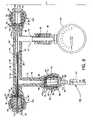
- FIG. 1is a view showing the overall outwardly visible structure of a gas inflation/evacuation system incorporating a multiple element valved guidewire assembly having an occlusive device, one embodiment of the present invention
- FIG. 2is an exploded vertical cross section view through the manifold assembly
- FIG. 3is an assembled vertical cross section view through the manifold assembly
- FIGS. 4 a and 4 bare isometric views of one of the self-sealing hemostatic valves which align in and which are housed in a proximal cavity, a distal cavity, and an inflation/evacuation branch cavity;
- FIG. 5is a cross section view of a valve along line 5 - 5 of FIG. 1 where the valve is in the closed position;
- FIG. 6is a cross section view of the valve along line 5 - 5 of FIG. 1 where the valve is in the open position;
- FIG. 7is a view of the gas inflation/evacuation system incorporating a multiple element valved guidewire assembly having an occlusive device in use within a blood vessel;
- FIG. 8is a cross section view like FIG. 3 but showing the valve of the multiple element valved guidewire assembly sealingly located in the main passageway of the manifold;
- FIG. 10is a view showing the overall outwardly visible structure of a gas inflation/evacuation system incorporating a multiple element valved guidewire assembly having an occlusive device using an attached vacuum syringe and an attached inflation syringe.
- the gas inflation/evacuation system incorporating a multiple element valved guidewire assembly having an occlusive device 10comprises a multiple element valved guidewire assembly 12 , a manifold assembly 14 , an evacuation syringe 16 and an inflation syringe 18 .
- a sealing rod 32which is flexible and of a round cross section in close tolerance slidable and sealing fit with opening 29 ( FIG. 5 ) provided by the seal 30 .
- a flexible support extension 34having a round cross section less than the round opening provided by the seal 30 and being continuous with the sealing rod 32 extends distally from the sealing rod 32 .
- the support extension 34 and the sealing rod 32are positionable within and through the seal 30 at the proximal end of the guidewire tube 20 .
- the arrangement of components as just describedalso constitutes and makes possible the operation of a valve 37 , as described in detail with reference to FIGS. 5 and 6 .
- the manifold assembly 14removably accommodates and attaches to and cooperates with the multiple element valved guidewire assembly 12 and cooperates with the evacuation syringe 16 and the inflation syringe 18 to provide for inflation and deflation of the occlusive balloon 22 at the distal end of the guidewire tube 20 .
- Readily visible components of the manifold assembly 14include a manifold 36 of tubular configuration, a manifold body 38 , a plurality of similarly constructed hemostatic nuts including a proximal hemostatic nut 40 a opposing a distal hemostatic nut 40 b at the ends of the manifold body 38 , and an inflation/evacuation branch hemostatic nut 40 c located at the end of an inflation/evacuation branch 42 .
- FIGS. 2 and 3are exploded and assembled vertical cross section views through the manifold assembly 14 .
- the manifold assembly 14includes structure for accommodation of the multiple element valved guidewire assembly 12 and for use of the evacuation and inflation syringes 16 and 18 , respectively.
- the manifold body 38 of the manifold 36includes connected and communicating passageways and cavities including a longitudinally oriented main passageway 62 being tapered in opposing directions extending through the central and tubular region of the manifold body 38 to communicate with opposed proximal and distal cavities 64 and 66 , which preferably are cylindrical, located centrally in opposed proximal and distal cavity bodies 68 and 70 at the ends of the manifold body 38 .
- An inflation/evacuation branch passageway 72which is tapered, extends along the interior of the inflation/evacuation branch 42 between the main passageway 62 and an inflation/evacuation branch cavity 74 , which preferably is cylindrical, located in an inflation/evacuation branch cavity body 76 .
- a pressure monitor branch passageway 78extends along the interior of the pressure monitor branch 44 between the main passageway 62 and a flange 80 for connection with the connector 46 and the pressure gauge 45 .
- proximal cavity body 68the distal cavity body 70 , the inflation/evacuation branch cavity body 76 and accordingly, the associated proximal cavity 64 , distal cavity 66 , and the inflation/evacuation branch cavity 74 , respectively, are fashioned similarly and as such contain like components and features identified by like reference numerals.
- the proximal cavity 64 , the distal cavity 66 and the inflation/evacuation branch cavity 74are tubular, each including a cavity wall 82 and a planar surface 84 which is annular and circular and which intersects the cavity wall 82 .
- An orifice 86 in eachis located central to the surface 84 and is common either to the proximal cavity 64 and the main passageway 62 , to the distal cavity 66 and the main passageway 62 , or to the inflation/evacuation branch cavity 74 and the inflation/evacuation branch passageway 72 .
- Each of the hemostatic nuts 40 a - 40 cincludes a centrally located cylindrical boss 94 and a beveled entryway 95 leading to a passageway 96 extending through and in part defining the cylindrical boss 94 .
- An annular cavity 100is located about a portion of the cylindrical boss 94 .
- Internal threads 98 of the hemostatic nuts 40 a - 40 c and the annular cavities 100 of the hemostatic nuts 40 a - 40 caccommodate the outwardly facing ends of the proximal and distal cavity bodies 68 and 70 and the inflation/evacuation branch cavity body 76 , including the external threads 92 and the rings 88 , respectively.
- the self-sealing hemostatic valves 106are captured in the proximal cavity body 68 , the distal cavity body 70 and the inflation/evacuation branch cavity body 76 by engagement of the hemostatic nuts 40 a - 40 c to the proximal cavity 64 , the distal cavity 66 or the inflation/evacuation branch cavity 74 of the manifold 36 . Also included in the hemostatic nuts 40 a - 40 c is an annular lip 104 which can be utilized for snap engagement of particular styles or types of introducers as required. Beneficial to the instant invention is the use of self-sealing hemostatic valves 106 , the shape of which and the functions of which are described later in detail.
- the self-sealing hemostatic valves 106which are slightly oversize with respect to the proximal cavity 64 , the distal cavity 66 or the inflation/evacuation branch cavity 74 , are aligned in and housed in such cavities at locations about the manifold 36 .
- FIGS. 4 a and 4 bare isometric views of one of the self-sealing hemostatic valves 106 which align in and which are housed in the proximal cavity 64 , the distal cavity 66 , and the inflation/evacuation branch cavity 74 adjacent to and in contact with the planar surface 84 in such cavities at the ends of the manifold 36 and the end of the inflation/evacuation branch 42 .
- FIG. 4 ais a proximal view of the self-sealing hemostatic valve 106
- FIG. 4 bis a distal view of such self-sealing hemostatic valve 106 associated with the proximal cavity 64 .
- the self-sealing hemostatic valve 106is compressible and multi-dimensional and sealingly expandable.
- the self-sealing hemostatic valve 106is formed of medical grade silicone material and is symmetrically fashioned to include opposing mirror-like planar and circular-shaped faces 108 and 110 having opposing radiused recessed surfaces 112 and 114 extending therebetween and a circumferential edge 116 between the circular-shaped faces 108 and 110 .
- the medical grade silicone material between the opposing radiused recessed surfaces 112 and 114is increasingly thinner in a direction towards the center and is parted or otherwise separated to form a plurality of slits 118 a - 118 n , each slit extending outwardly in radial fashion from the center of the self-sealing hemostatic valve 106 part of the distance along and between the radiused recessed surfaces 112 and 114 , thus creating boundaries beneficial in defining lobes 120 a - 120 n .
- lobe 120 ais located between slits 118 a and 118 b
- lobe 120 bis located between slits 118 b and 118 n
- lobe 120 nis located between slits 118 n and 118 a .
- Adjacent lobes 120 a - 120 nare in mutual contact along the slits 118 a - 118 n to effect a seal from side-to-side of the self-sealing hemostatic valve 106 .
- the silicone material of the self-sealing hemostatic valve 106could be pierced between the recessed surfaces 112 and 114 to yet maintain a self-sealing quality.
- the self-sealing hemostatic valve 106is preferably constructed of medical grade silicone or can be fashioned of other suitable flexible, pliable and resilient material which can conform to and about existing shapes or forms as required, such as to a guidewire or needle.
- the degree of flexibility of the lobes 120 a - 120 nis influenced by the thickness of the lobes 120 a - 120 n each of which contains a portion of the radiused recessed surfaces 112 and 114 .
- a guidewire, guidewire tube 20 or other round cross section device or membercan pass between the inner tips of the lobes 120 a - 120 n while maintaining a seal therebetween with the self-sealing hemostatic valve 106 . Due to the similar geometrical configuration of the opposing faces and associated structure therebetween, the self-sealing hemostatic valve 106 can be inserted into a cavity without regard to orientation of the self-sealing hemostatic valve 106 .
- the diameter of the self-sealing hemostatic valve 106can be slightly larger than that of the cavities 64 , 66 or 74 to provide for flexible, but snug, frictional engagement of the self-sealing hemostatic valve 106 within the cavities 64 , 66 or 74 , as well as providing for circumferential sealing of the self-sealing hemostatic valve 106 to the cavities 64 , 66 or 74 .
- Compressive forceis transmitted into the self-sealing hemostatic valve 106 by tightening action of the proximal, distal and inflation/evacuation branch hemostatic nuts 40 a - 40 c to compress the self-sealing hemostatic valve 106 around tubes, guidewires, or other elongated elements that pass through the self-sealing hemostatic valve 106 .
- the self-sealing hemostatic valve 106operates automatically; that is, when the self-sealing hemostatic valve 106 is penetrated by a tube, wire, or other elongated element inserted therethrough, the compressed self-sealing hemostatic valve 106 automatically causes sealing around the element that has penetrated it.
- FIG. 6is a cross section view of the valve 37 along line 5 - 5 of FIG. 1 where the valve 37 is in the open position such as for relieving pressure within the lumen 26 of the guidewire tube 20 to allow collapsing of the occlusive balloon 22 , as later described on the mode of operation. As illustrated, urging of the sealing rod 32 proximally removes the sealing rod 32 from the influence of the seal 30 , thereby equalizing pressures distal and proximal of the seal 30 .
- any number of other alloys or polymer materials and attachment techniquescould be used in the construction of the multiple element valved guidewire assembly 12 provided the materials offer the flexibility and torque characteristics required for a guidewire and the attachment techniques are sufficiently strong enough and capable of making an airtight seal.
- These materialsinclude, but are not limited to, Ni—Ti, 17-7 stainless steel, _304 stainless steel, cobalt superalloys, or other polymer, braided or alloy materials.
- the attachment techniques for constructing multiple element valved guidewire assembly 12include, but are not limited to, welding, mechanical fits, adhesives, sleeve arrangements, or any combination thereof.
- the occlusive balloon 22may be made of any number of polymer or rubber materials.
- the occlusive balloon 22is preinflated to prestretch it so that expansion is more linear with pressure.
- the pressure supplied by the gas inflation/evacuation system incorporating a multiple element valved guidewire assembly having an occlusive device 10is designed to stay well within the elastic limit of the occlusive balloon 22 .
- a two-layer occlusive balloon arrangement, adding gas and/or liquid between balloon layers,may be used as an alternative to increase visibility of the distal end of the multiple element valved guidewire assembly 12 under fluoroscopy.
- the instant inventionis generally used in the following manner where a patient is prepared for a common interventional procedure involving the ablative removal of thrombus, plaque, lesions and the like, for instance, via a femoral arterial access or other suitable vascular site.
- the distal end of the multiple element valved guidewire assembly 12is inserted alone or through a pre-positioned sheath, a guide catheter or an introducer and is tracked to a preferred location distal to the buildup site.
- the occlusive balloon 22can be repeatedly inflated and deflated as required to controllingly and appropriately allow blood flow, to actively function as an occlusive device.
- FIG. 8is a cross section view like FIG. 3 but showing the valve 37 of the multiple element valved guidewire assembly 12 sealingly located in the main passageway 62 of the manifold 36 .
- FIG. 9is a view like FIG. 7 but showing the occlusive balloon 22 inflated to occlude the blood vessel 124 .
- the method and manner of operation of the present inventionis now set forth.
- the proximal end of the multiple element valved guidewire assembly 12(more specifically, the proximal end of the sealing rod 32 ) is inserted into the proximal hemostatic nut 40 a to seal within the self-sealing hemostatic valve 106 therein and to pass into and through the main passageway 62 of the manifold body 38 until passing through and sealing within the self-sealing hemostatic valve 106 of the distal hemostatic nut 40 b to position the valve 37 between the proximal and distal hemostatic nuts 40 a and 40 b in the main passageway 62 .
- the valve 37 within the main passageway 62is in a location to selectively allow communication between the lumen 26 and attached occlusive balloon 22 of the guidewire tube 20 with the main passageway 62 , with the inflation/evacuation branch passageway 72 of the inflation/evacuation branch 42 , and with the pressure monitor branch passageway 78 of the pressure monitor branch 44 .
- the self-sealing hemostatic valves 106 in the proximal cavity 64 , in the distal cavity 66 , and in the inflation/evacuation branch cavity 74seal the ends of the main passageway 62 and the end of the inflation/evacuation branch passageway 72 , respectively, to provide for a sealed but accessible interior of the manifold assembly 14 .
- the needle 54 of the evacuation syringe 16is inserted through the self-sealing hemostatic valve 106 associated with the inflation/evacuation branch hemostatic nut 40 c , and the plunger 48 of the evacuation syringe 16 is withdrawn to evacuate the main passageway 62 , the inflation/evacuation branch passageway 72 and the pressure monitor branch passageway 78 of the manifold assembly 14 where the vacuum (or pressure) is observed on the pressure gauge 45 . Accordingly, when the valve 37 is in the open position by positioning of the sealing rod 32 , such as shown in FIG.
- the lumen 26 of the guidewire tube 20 and the occlusive balloon 22are in common communication with main passageway 62 of the manifold body 38 and also subjected to the applied vacuum and are also evacuated. Such evacuation also minimizes the profile of the occlusive balloon 22 .
- the check valve 50 of the evacuation syringe 16functions to stabilize and maintain the outwardly advanced position of the plunger 48 during evacuation. The evacuation syringe 16 is then withdrawn from engagement with the automatically self-sealing hemostatic valve 106 associated with the inflation/evacuation branch hemostatic nut 40 c leaving the manifold assembly 14 and the multiple element valved guidewire assembly 12 in a sealed and evacuated state.
- the needle 60 of the inflation syringe 18is then inserted through the self-sealing hemostatic valve 106 associated with the inflation/evacuation branch hemostatic nut 40 c , and the plunger 56 of the inflation syringe 18 is depressed to dispel and urge a suitable quantity of biocompatible inflation medium, preferably a gaseous medium, from the interior of the inflation syringe 18 into the interior of the manifold 36 and thence through the open valve 37 and through lumen 26 of the guidewire tube 20 to inflate the occlusive balloon 22 while observing the pressure gauge 45 where appropriately used volumes can be observed by viewing a displaceable piston 61 located in the inflation syringe 18 .
- a suitable quantity of biocompatible inflation mediumpreferably a gaseous medium
- the inflation mediumis a gas such as carbon dioxide or helium which are biocompatible and which dissolve easily in blood or which will not form a gas embolus.
- the check valve 58 of the inflation syringe 18functions to stabilize and maintain the inwardly advanced position of the plunger 56 during inflation.
- valve 37is then closed by urging the sealing rod 32 in a distal direction to achieve closure of the valve 37 , as depicted in FIG. 5 , wherein the multiple element valved guidewire assembly 12 maintains pressure within the lumen 26 and within the occlusive balloon 22 , and wherein the occlusive balloon 22 maintains an inflated state in intimate and sealing contact with the interior of the blood vessel 124 , as shown in FIG. 9 .
- the inflation syringe 18can be withdrawn from the automatically self-sealing hemostatic valve 106 associated with the hemostatic nut 40 c .
- the manifold assembly 14is then disengaged in a proximal direction from the multiple element valved guidewire assembly 12 leaving the pressurized multiple element valved guidewire assembly 12 undisturbed in the vascular site, i.e., the inflated occlusive balloon 22 is left in place in the blood vessel 124 with the guidewire tube 20 , whereupon the guidewire tube 20 can function as a guidewire.
- the guidewire tube 20 along with the sealing rod 32 of the multiple element valved guidewire assembly 12is then utilized unitarily for guidance of other devices, such as catheters, thrombectomy catheters, stents, and the like, to a vascular site proximal of the inflated occlusive balloon 22 .
- An ablation or other procedureis performed for a time period consistent with the desired maximum length for blockage of the particular vessel after which the valve 37 may be opened by repositioning the sealing rod 32 , such as shown in FIG. 6 , to equalize internal pressure with atmospheric pressure to rapidly deflate the occlusive balloon 22 , thereby reestablishing blood flow within the vessel 124 .
- the occlusive balloon 22can be re-inflated and the valve 37 reclosed to continue with thrombus removal or to initiate another procedure.
- the multiple element valved guidewire assembly 12may be removed from the vessel or left in place.
- an evacuation of any plaque material or other debris dislodged by the therapyis accomplished before deflation of the occlusive balloon 22 .
- Removal of the multiple element valved guidewire assembly 12 from the vasculatureis accomplished by repositioning of the sealing rod 32 to open the valve 37 to atmosphere to collapse the occlusive balloon 22 for withdrawal.
- a further reduction of the physical cross section of the occlusive balloon 22 for minimum profile removal of the multiple element valved guidewire assembly 12 , i.e., the occlusive balloon 22can be accomplished by reinserting the proximal end of the sealing rod 32 of the multiple element valved guidewire assembly 12 into the manifold assembly 14 , if not already present, and accomplishing the evacuation steps outlined in steps 1 and 2 above.
- FIG. 10is a view showing the overall outwardly visible structure of a gas inflation/evacuation system incorporating a multiple element valved guidewire assembly having an occlusive device 10 a incorporating many of the principles and components of the gas inflation/evacuation system incorporating a multiple element valved guidewire assembly having an occlusive device 10 .
- the evacuation syringe 16 and the inflation syringe 18are threadingly engaged to a manifold assembly 14 a via an intermediate positionable valve 130 , thus negating the use of the needles 54 and 60 previously shown.
- the use of the inflation/evacuation branch cavity body 76is not required, nor is the associated self-sealing hemostatic valve 106 , as sealing is accomplished by the positionable valve 130 . Accordingly, the inflation/evacuation branch hemostatic nut 40 c and associated self-sealing hemostatic valve 106 are not incorporated therein. Operation of the gas inflation/evacuation system incorporating a multiple element valved guidewire assembly having an occlusive device 10 a is much the same as previously described, but differs in that the positionable valve 130 determines whether the evacuation syringe 16 or the inflation syringe 18 is in communication with the main passageway 62 through the inflation/evacuation branch 42 .
Landscapes
- Health & Medical Sciences (AREA)
- Life Sciences & Earth Sciences (AREA)
- Heart & Thoracic Surgery (AREA)
- Biomedical Technology (AREA)
- Biophysics (AREA)
- Pulmonology (AREA)
- Engineering & Computer Science (AREA)
- Anesthesiology (AREA)
- Child & Adolescent Psychology (AREA)
- Hematology (AREA)
- Animal Behavior & Ethology (AREA)
- General Health & Medical Sciences (AREA)
- Public Health (AREA)
- Veterinary Medicine (AREA)
- Surgical Instruments (AREA)
- Media Introduction/Drainage Providing Device (AREA)
Abstract
Description
- 10 gas inflation/evacuation system incorporating a multiple element valved guidewire assembly having an occlusive device
- 10agas inflation/evacuation system incorporating a multiple element valved guidewire assembly having an occlusive device
- 12 multiple element valved guidewire assembly
- 14 manifold assembly
- 14amanifold assembly
- 16 evacuation syringe
- 18 inflation syringe
- 20 guidewire tube
- 22 occlusive balloon
- 24 inflation orifice
- 26 lumen
- 27 proximal end
- 28 flexible tip
- 29 opening
- 30 seal
- 32 sealing rod
- 34 support extension
- 36 manifold
- 37 valve
- 38 manifold body
- 40aproximal hemostatic nut
- 40bdistal hemostatic nut
- 40cinflation/evacuation branch hemostatic nut
- 42 inflation/evacuation branch
- 44 pressure monitor branch
- 45 pressure gauge
- 46 connector
- 48 plunger
- 50 check valve
- 52 connector
- 54 needle
- 56 plunger
- 58 check valve
- 60 needle
- 61 displaceable piston
- 62 main passageway
- 64 proximal cavity
- 66 distal cavity
- 68 proximal cavity body
- 70 distal cavity body
- 72 inflation/evacuation branch passageway
- 74 inflation/evacuation branch cavity
- 76 inflation/evacuation branch cavity body
- 78 pressure monitor branch passageway
- 80 flange
- 82 cavity wall
- 84 planar surface
- 86 orifice
- 88 ring
- 90 angled annular surface
- 92 external threads
- 94 cylindrical boss
- 95 beveled entryway
- 96 passageway
- 98 internal threads
- 100 annular cavity
- 102 ring
- 104 annular lip
- 106 self-sealing hemostatic valve
- 108 face
- 110 face
- 112 recessed surface
- 114 recessed surface
- 116 circumferential edge
- 118a-nslits
- 120a-nlobes
- 122 thrombus, plaque, or lesions
- 124 blood vessel
- 130 positionable valve
Claims (24)
Priority Applications (3)
| Application Number | Priority Date | Filing Date | Title |
|---|---|---|---|
| US11/217,546US7615031B2 (en) | 2005-09-01 | 2005-09-01 | Gas inflation/evacuation system incorporating a multiple element valved guidewire assembly having an occlusive device |
| PCT/US2006/033428WO2007027563A2 (en) | 2005-09-01 | 2006-08-28 | Gas inflation/evacuation system incorporating a multiple element valved guidewire assembly having an occlusive drive |
| EP06802420AEP1922106A4 (en) | 2005-09-01 | 2006-08-28 | Gas inflation/evacuation system incorporating a multiple element valved guidewire assembly having an occlusive drive |
Applications Claiming Priority (1)
| Application Number | Priority Date | Filing Date | Title |
|---|---|---|---|
| US11/217,546US7615031B2 (en) | 2005-09-01 | 2005-09-01 | Gas inflation/evacuation system incorporating a multiple element valved guidewire assembly having an occlusive device |
Publications (2)
| Publication Number | Publication Date |
|---|---|
| US20070060881A1 US20070060881A1 (en) | 2007-03-15 |
| US7615031B2true US7615031B2 (en) | 2009-11-10 |
Family
ID=37809395
Family Applications (1)
| Application Number | Title | Priority Date | Filing Date |
|---|---|---|---|
| US11/217,546Expired - Fee RelatedUS7615031B2 (en) | 2005-09-01 | 2005-09-01 | Gas inflation/evacuation system incorporating a multiple element valved guidewire assembly having an occlusive device |
Country Status (3)
| Country | Link |
|---|---|
| US (1) | US7615031B2 (en) |
| EP (1) | EP1922106A4 (en) |
| WO (1) | WO2007027563A2 (en) |
Cited By (7)
| Publication number | Priority date | Publication date | Assignee | Title |
|---|---|---|---|---|
| US20060058734A1 (en)* | 2004-09-15 | 2006-03-16 | Phillips John C | Self-sealing male Luer connector with molded elastomeric tip |
| US20100180678A1 (en)* | 2009-01-21 | 2010-07-22 | Casner Jonathan S | Inflation Valve and Pressure Gauge With Over Pressure Protection |
| US20150377417A1 (en)* | 2013-03-13 | 2015-12-31 | Scott Technologies, Inc. | Base Manifold and System for Filling Containers with Gas |
| US20160346517A1 (en)* | 2014-01-17 | 2016-12-01 | Acutus Medical, Inc. | Gas-elimination patient access device |
| US10463232B2 (en) | 2010-10-18 | 2019-11-05 | Sanovas Intellectual Property, Llc | Anchored guidewire |
| US11284900B2 (en) | 2018-06-21 | 2022-03-29 | RenalPro Medical, Anc. | Gas inflation devices, systems, and methods |
| US11602617B2 (en) | 2019-04-18 | 2023-03-14 | Michael Bonnette | Pumpless thrombectomy system |
Families Citing this family (10)
| Publication number | Priority date | Publication date | Assignee | Title |
|---|---|---|---|---|
| US20060064071A1 (en)* | 2001-11-06 | 2006-03-23 | Possis Medical, Inc. | Gas inflation/evacuation system incorporating a reservoir and removably attached sealing system for a guidewire assembly having an occlusive device |
| US7615031B2 (en) | 2005-09-01 | 2009-11-10 | Medrad, Inc. | Gas inflation/evacuation system incorporating a multiple element valved guidewire assembly having an occlusive device |
| US20070060878A1 (en) | 2005-09-01 | 2007-03-15 | Possis Medical, Inc. | Occlusive guidewire system having an ergonomic handheld control mechanism and torqueable kink-resistant guidewire |
| US8608703B2 (en) | 2007-06-12 | 2013-12-17 | Medrad, Inc. | Infusion flow guidewire system |
| US20080097294A1 (en)* | 2006-02-21 | 2008-04-24 | Possis Medical, Inc. | Occlusive guidewire system having an ergonomic handheld control mechanism prepackaged in a pressurized gaseous environment and a compatible prepackaged torqueable kink-resistant guidewire with distal occlusive balloon |
| US20110092967A1 (en)* | 2009-10-21 | 2011-04-21 | Medtronic Cryocath Lp | Deflation mechanism for a medical device |
| CN201719305U (en)* | 2010-07-14 | 2011-01-26 | 乐普(北京)医疗器械股份有限公司 | Hemostat inflating and deflating device |
| WO2012021697A1 (en) | 2010-08-12 | 2012-02-16 | Medrad, Inc. | Infusion flow system and fluid coupling |
| US10786659B2 (en)* | 2016-06-01 | 2020-09-29 | Microvention, Inc. | Reinforced balloon catheter |
| US10813648B2 (en) | 2017-10-06 | 2020-10-27 | Boehringer Technologies, Lp | Systems and methods for effecting the total and partial occlusion of the aorta of a living being |
Citations (117)
| Publication number | Priority date | Publication date | Assignee | Title |
|---|---|---|---|---|
| US3773290A (en) | 1971-06-01 | 1973-11-20 | Sta Rite Industries | Clamping device for a flexible hose |
| US3913938A (en) | 1973-07-04 | 1975-10-21 | Nissan Motor | Self-levelling vehicle suspension system |
| US4122556A (en) | 1977-03-23 | 1978-10-31 | Stanley Poler | Intra-ocular lens |
| US4166807A (en) | 1976-12-08 | 1979-09-04 | Mitsubishi Gas Chemical Company, Inc. | Oxygen absorbent |
| US4332254A (en) | 1980-11-17 | 1982-06-01 | Advanced Catheter Systems, Inc. | System for filling and inflating and deflating a vascular dilating cathether assembly |
| US4381765A (en) | 1981-04-02 | 1983-05-03 | Waters Instruments, Inc. | Ileostomy valve |
| US4467003A (en) | 1978-12-18 | 1984-08-21 | Safta S.P.A. | Valves for sterilizable flat flexible containers and process for their manufacture |
| US4573470A (en) | 1984-05-30 | 1986-03-04 | Advanced Cardiovascular Systems, Inc. | Low-profile steerable intraoperative balloon dilitation catheter |
| US4573966A (en) | 1981-11-24 | 1986-03-04 | Schneider Medintag Ag | Method and apparatus for removing and/or enlarging constricted areas in vessels conducting body fluids |
| US4636195A (en) | 1982-04-02 | 1987-01-13 | Harvey Wolinsky | Method and apparatus for removing arterial constriction |
| US4646719A (en) | 1984-06-11 | 1987-03-03 | Aries Medical Incorporated | Intra-aortic balloon catheter having flexible torque transmitting tube |
| US4651738A (en) | 1985-08-02 | 1987-03-24 | Baylor College Of Medicine | Method and device for performing transluminal angioplasty |
| US4653539A (en) | 1984-06-12 | 1987-03-31 | Mallinckrodt, Inc. | Self-sealing check valve |
| US4733652A (en) | 1985-12-31 | 1988-03-29 | Aisin Seiki Kabushiki Kaisha | Intra-aortic balloon |
| US4748986A (en) | 1985-11-26 | 1988-06-07 | Advanced Cardiovascular Systems, Inc. | Floppy guide wire with opaque tip |
| US4757827A (en) | 1987-02-17 | 1988-07-19 | Versaflex Delivery Systems Inc. | Steerable guidewire with deflectable tip |
| US4758223A (en) | 1986-07-02 | 1988-07-19 | Schneider-Shiley (Usa) Inc. | Inflation device for angioplasty catheter |
| US4832023A (en) | 1987-06-03 | 1989-05-23 | Mcm Laboratories, Inc. | Method and apparatus for reducing blockage in body channels |
| US4838268A (en) | 1988-03-07 | 1989-06-13 | Scimed Life Systems, Inc. | Non-over-the wire balloon catheter |
| US4865587A (en) | 1987-01-14 | 1989-09-12 | Walling Peter T | Syringe and catheter apparatus |
| US5014494A (en) | 1988-09-27 | 1991-05-14 | Sherwood Medical Company | Method of sterilizing medical articles |
| US5059178A (en) | 1988-08-03 | 1991-10-22 | Ya Wang D | Method of percutaneously removing a thrombus from a blood vessel by using catheters and system for removing a thrombus from a blood vessel by using catheters |
| US5059176A (en) | 1989-12-21 | 1991-10-22 | Winters R Edward | Vascular system steerable guidewire with inflatable balloon |
| US5102395A (en)* | 1991-06-26 | 1992-04-07 | Adam Spence Corporation | Hemostasis valve |
| US5106363A (en) | 1988-10-11 | 1992-04-21 | Terumo Kabushiki Kaisha | Blood perfusion system and tube used therein |
| US5135482A (en) | 1985-12-31 | 1992-08-04 | Arnold Neracher | Hydrodynamic device for the elimination of an organic deposit obstructing a vessel of a human body |
| US5167239A (en) | 1991-05-30 | 1992-12-01 | Endomedix Corporation | Anchorable guidewire |
| US5171221A (en) | 1991-02-05 | 1992-12-15 | Target Therapeutics | Single lumen low profile valved balloon catheter |
| US5176692A (en) | 1991-12-09 | 1993-01-05 | Wilk Peter J | Method and surgical instrument for repairing hernia |
| US5195955A (en) | 1989-11-14 | 1993-03-23 | Don Michael T Anthony | Device for removal of embolic debris |
| US5196245A (en) | 1991-04-01 | 1993-03-23 | General Electric Company | Irradiation resistant functionally encapped polycarbonate |
| US5207656A (en) | 1990-04-19 | 1993-05-04 | Cordis Corporation | Medical instrument valve having foam partition member |
| US5209727A (en) | 1992-01-29 | 1993-05-11 | Interventional Technologies, Inc. | Guide wire with integral angioplasty balloon |
| US5320604A (en) | 1991-04-24 | 1994-06-14 | Baxter International Inc. | Low-profile single-lumen dual-balloon catheter with integrated guide wire for embolectomy dilatation/occlusion and delivery of treatment fluid |
| US5324260A (en) | 1992-04-27 | 1994-06-28 | Minnesota Mining And Manufacturing Company | Retrograde coronary sinus catheter |
| US5334153A (en) | 1992-10-07 | 1994-08-02 | C. R. Bard, Inc. | Catheter purge apparatus and method of use |
| DE4221126C2 (en) | 1992-06-26 | 1994-08-11 | Hemscheidt Maschf Hermann | Hydropneumatic suspension system |
| US5338010A (en) | 1990-06-28 | 1994-08-16 | Zahnradfabrik Friedrichshafen Ag | Hydropneumatic vehicle suspension |
| US5365943A (en) | 1993-03-12 | 1994-11-22 | C. R. Bard, Inc. | Anatomically matched steerable PTCA guidewire |
| US5380284A (en) | 1993-08-13 | 1995-01-10 | Don Michael; T. Anthony | Obstruction dissolution catheter with variably expanding blocking balloons and method of use |
| US5399658A (en) | 1993-10-29 | 1995-03-21 | Miles Inc. | Gamma-radiation-resistant polycarbonate composition |
| US5413581A (en) | 1990-10-04 | 1995-05-09 | Schneider (Europe) A.G. | Method of using a balloon dilatation catheter and a guidewire |
| US5474194A (en) | 1990-07-09 | 1995-12-12 | Continental White Cap, Inc. | Closure with irreversible color change system |
| US5505699A (en) | 1994-03-24 | 1996-04-09 | Schneider (Usa) Inc. | Angioplasty device |
| US5514109A (en) | 1992-12-17 | 1996-05-07 | Thomas J. Fogarty | Adjustable valve having a radially compressible sealing body |
| US5520645A (en) | 1994-10-28 | 1996-05-28 | Intelliwire, Inc. | Low profile angioplasty catheter and/or guide wire and method |
| US5583047A (en) | 1992-12-10 | 1996-12-10 | W. R. Grace & Co.-Conn. | Method of detecting the permeability of an object to oxygen |
| US5584843A (en) | 1994-12-20 | 1996-12-17 | Boston Scientific Corporation | Shaped wire multi-burr rotational ablation device |
| US5601306A (en) | 1993-10-28 | 1997-02-11 | Kinetic Limited | Vehicle suspension system |
| US5605543A (en) | 1994-03-10 | 1997-02-25 | Schneider (Usa) Inc. | Catheter having shaft of varying stiffness |
| US5688234A (en) | 1996-01-26 | 1997-11-18 | Cardiometrics Inc. | Apparatus and method for the treatment of thrombotic occlusions in vessels |
| US5713917A (en) | 1995-10-30 | 1998-02-03 | Leonhardt; Howard J. | Apparatus and method for engrafting a blood vessel |
| US5776100A (en) | 1995-09-27 | 1998-07-07 | Interventional Innovations Corporation | Nickel titanium guide wires for occlusion and drug delivery |
| US5775327A (en) | 1995-06-07 | 1998-07-07 | Cardima, Inc. | Guiding catheter for the coronary sinus |
| US5779688A (en) | 1994-10-28 | 1998-07-14 | Intella Interventional Systems, Inc. | Low profile balloon-on-a-wire catheter with shapeable and/or deflectable tip and method |
| US5792179A (en) | 1996-07-16 | 1998-08-11 | Sideris; Eleftherios B. | Retrievable cardiac balloon placement |
| US5794325A (en) | 1996-06-07 | 1998-08-18 | Harris Corporation | Electrically operated, spring-biased cam-configured release mechanism for wire cutting and seating tool |
| US5795325A (en) | 1991-07-16 | 1998-08-18 | Heartport, Inc. | Methods and apparatus for anchoring an occluding member |
| US5807330A (en) | 1996-12-16 | 1998-09-15 | University Of Southern California | Angioplasty catheter |
| US5827324A (en) | 1997-03-06 | 1998-10-27 | Scimed Life Systems, Inc. | Distal protection device |
| US5833650A (en) | 1995-06-05 | 1998-11-10 | Percusurge, Inc. | Catheter apparatus and method for treating occluded vessels |
| US5833644A (en) | 1996-05-20 | 1998-11-10 | Percusurge, Inc. | Method for emboli containment |
| US5843022A (en) | 1995-10-25 | 1998-12-01 | Scimied Life Systems, Inc. | Intravascular device utilizing fluid to extract occlusive material |
| US5865721A (en) | 1993-12-20 | 1999-02-02 | C. R. Bard, Inc. | Intra-aortic balloon catheters |
| US5881534A (en) | 1994-06-08 | 1999-03-16 | Pharmacia & Upjohn Ab | Process for sterilization by radiation and by the use of an oxygen absorber, a container and a medical article sterilized by the process |
| US5925016A (en) | 1995-09-27 | 1999-07-20 | Xrt Corp. | Systems and methods for drug delivery including treating thrombosis by driving a drug or lytic agent through the thrombus by pressure |
| US5938672A (en) | 1996-07-26 | 1999-08-17 | Kensey Nash Corporation | System and method of use for revascularizing stenotic bypass grafts and other blood vessels |
| US6009708A (en) | 1996-12-03 | 2000-01-04 | Shin Caterpillar Mitsubishi Ltd. | Control apparatus for construction machine |
| US6022336A (en) | 1996-05-20 | 2000-02-08 | Percusurge, Inc. | Catheter system for emboli containment |
| US6036715A (en) | 1986-04-15 | 2000-03-14 | Yock; Paul G. | Angioplasty apparatus facilitating rapid exchanges |
| US6050972A (en) | 1996-05-20 | 2000-04-18 | Percusurge, Inc. | Guidewire inflation system |
| US6080170A (en) | 1996-07-26 | 2000-06-27 | Kensey Nash Corporation | System and method of use for revascularizing stenotic bypass grafts and other occluded blood vessels |
| US6123698A (en) | 1995-11-27 | 2000-09-26 | Therox, Inc. | Angioscopy apparatus and methods |
| US6135991A (en) | 1997-03-06 | 2000-10-24 | Percusurge, Inc. | Aspiration method |
| US6145859A (en) | 1997-10-31 | 2000-11-14 | Deere & Company | Hydro-pneumatic driven axle suspension |
| US6146372A (en) | 1998-12-24 | 2000-11-14 | Datascope Investment Corp | Apparatus and method for the percutaneous insertion of a pediatric intra-aortic balloon catheter |
| US6159195A (en) | 1998-02-19 | 2000-12-12 | Percusurge, Inc. | Exchange catheter and method of use |
| US6161695A (en) | 1998-08-21 | 2000-12-19 | Depuy Orthopaedics, Inc. | Protective packaging unit |
| US6166116A (en) | 1999-06-03 | 2000-12-26 | The Dow Chemical Company | Carbonate polymer compositions stabilized against discoloration and physical property deterioration during sterilization by ionizing radiation |
| US6171328B1 (en) | 1999-11-09 | 2001-01-09 | Embol-X, Inc. | Intravascular catheter filter with interlocking petal design and methods of use |
| US6176844B1 (en)* | 1997-05-22 | 2001-01-23 | Peter Y. Lee | Catheter system for the isolation of a segment of blood vessel |
| US6190354B1 (en) | 1994-09-16 | 2001-02-20 | Scimed Life Systems, Inc. | Balloon catheter with improved pressure source |
| US6203561B1 (en) | 1999-07-30 | 2001-03-20 | Incept Llc | Integrated vascular device having thrombectomy element and vascular filter and methods of use |
| US6217567B1 (en) | 1997-03-06 | 2001-04-17 | Percusurge, Inc. | Hollow medical wires and methods of constructing same |
| US6231588B1 (en) | 1998-08-04 | 2001-05-15 | Percusurge, Inc. | Low profile catheter for angioplasty and occlusion |
| US6241706B1 (en) | 1999-07-16 | 2001-06-05 | Datascope Investment Corporation | Fast response intra-aortic balloon pump |
| US6245089B1 (en) | 1997-03-06 | 2001-06-12 | Scimed Life Systems, Inc. | Distal protection device and method |
| US6248121B1 (en) | 1998-02-18 | 2001-06-19 | Cardio Medical Solutions, Inc. | Blood vessel occlusion device |
| US20010014821A1 (en) | 1998-11-16 | 2001-08-16 | Mohamad Ike Juman | Balloon catheter and stent delivery system having enhanced stent retention |
| US20010016704A1 (en) | 1998-02-19 | 2001-08-23 | Gholam Reza Zadno-Azizi | Low profile fluid delivery and sealing system for a catheter |
| US20020096521A1 (en) | 2001-01-22 | 2002-07-25 | Venanzio Cardarelli | Tennis ball container safety shield |
| US6475185B1 (en) | 2000-02-24 | 2002-11-05 | Scimed Life Systems, Inc. | Occlusion device |
| US6485657B1 (en) | 1998-06-11 | 2002-11-26 | Teijin, Limited | Gamma-ray stabilizer and thermoplastic polymer compound including the said stabilizer |
| US6494314B1 (en) | 1997-04-10 | 2002-12-17 | Johns Hopkins University | Pre-filled package containing unit dose of medical gas and method of making same |
| US6511472B1 (en)* | 1999-05-21 | 2003-01-28 | Microtherapeutics, Inc. | Interface needle and method for creating a blunt interface between delivered liquids |
| US6544276B1 (en) | 1996-05-20 | 2003-04-08 | Medtronic Ave. Inc. | Exchange method for emboli containment |
| US6554794B1 (en)* | 1997-09-24 | 2003-04-29 | Richard L. Mueller | Non-deforming deflectable multi-lumen catheter |
| US20030088262A1 (en) | 2001-11-06 | 2003-05-08 | Possis Medical,Inc | Guidewire having occlusive device and repeatably crimpable proximal end |
| US20030088194A1 (en)* | 2001-11-06 | 2003-05-08 | Bonnette Michael J. | Gas Inflation/evacution system for guidewire having occlusive device |
| US20030088263A1 (en) | 2001-11-06 | 2003-05-08 | Possis Medical, Inc. | Guidewire occlusion system utilizing repeatably inflatable gas-filled occlusive device |
| US20030208134A1 (en) | 2001-05-07 | 2003-11-06 | Secrest Dean J. | Barrett's esophagus cytology device |
| US20040031721A1 (en) | 2000-11-01 | 2004-02-19 | Mann David Marshall | Kit for obtaining an endoarterial biopsy sample |
| US20040039306A1 (en) | 2002-08-26 | 2004-02-26 | Mark Eberhart | Crimp and cut tool for sealing and unsealing guide wires and tubular instruments |
| US20040039304A1 (en) | 2002-08-23 | 2004-02-26 | Connors John J. | Wire guide |
| US20040050740A1 (en) | 2001-01-25 | 2004-03-18 | Gareth Lewis | Tamper evident packaging |
| US6786492B2 (en) | 2001-02-15 | 2004-09-07 | Carl Freudenberg Kg | Method and device for controlling the suspension performance in vehicles having hydropneumatic suspension devices and highly variable axle-load ratios |
| US20050020998A1 (en) | 2001-11-06 | 2005-01-27 | Bonnette Michael J. | Gas inflation/evacuation system and sealing system incorporating a compression sealing mechanism for guidewire assembly having occlusive device |
| US6902535B2 (en) | 2002-08-26 | 2005-06-07 | Kansey Nash Corporation | Guide-wire mounted balloon modulation device and methods of use |
| US6927063B2 (en) | 1999-04-22 | 2005-08-09 | Ineos Silicas Limited | Humidity indicators |
| US20050182437A1 (en) | 2001-11-06 | 2005-08-18 | Bonnette Michael J. | Guidewire assembly including a repeatably inflatable occlusive balloon on a guidewire ensheathed with a spiral coil |
| US20060064071A1 (en) | 2001-11-06 | 2006-03-23 | Possis Medical, Inc. | Gas inflation/evacuation system incorporating a reservoir and removably attached sealing system for a guidewire assembly having an occlusive device |
| US20070060881A1 (en) | 2005-09-01 | 2007-03-15 | Posis Medical, Inc. | Gas inflation/evacuation system incorporating a multiple element valved guidewire assembly having an occlusive device |
| US20070060878A1 (en) | 2005-09-01 | 2007-03-15 | Possis Medical, Inc. | Occlusive guidewire system having an ergonomic handheld control mechanism and torqueable kink-resistant guidewire |
| US7219799B2 (en) | 2002-12-31 | 2007-05-22 | Possis Medical, Inc. | Packaging system with oxygen sensor |
| US7226433B2 (en) | 1998-02-06 | 2007-06-05 | Possis Medical, Inc. | Thrombectomy catheter device having a self-sealing hemostasis valve |
| US7334681B2 (en) | 2001-11-06 | 2008-02-26 | Possis Medical, Inc. | Packaging system with oxygen sensor for gas inflation/evacuation system and sealing system |
| US20080097294A1 (en) | 2006-02-21 | 2008-04-24 | Possis Medical, Inc. | Occlusive guidewire system having an ergonomic handheld control mechanism prepackaged in a pressurized gaseous environment and a compatible prepackaged torqueable kink-resistant guidewire with distal occlusive balloon |
Family Cites Families (2)
| Publication number | Priority date | Publication date | Assignee | Title |
|---|---|---|---|---|
| US3193938A (en)* | 1963-01-28 | 1965-07-13 | Sheffield Corp | Gaging device |
| US3653539A (en)* | 1969-11-26 | 1972-04-04 | Minnesota Mining & Mfg | Label dispensing mechanism |
- 2005
- 2005-09-01USUS11/217,546patent/US7615031B2/ennot_activeExpired - Fee Related
- 2006
- 2006-08-28EPEP06802420Apatent/EP1922106A4/ennot_activeWithdrawn
- 2006-08-28WOPCT/US2006/033428patent/WO2007027563A2/enactiveApplication Filing
Patent Citations (128)
| Publication number | Priority date | Publication date | Assignee | Title |
|---|---|---|---|---|
| US3773290A (en) | 1971-06-01 | 1973-11-20 | Sta Rite Industries | Clamping device for a flexible hose |
| US3913938A (en) | 1973-07-04 | 1975-10-21 | Nissan Motor | Self-levelling vehicle suspension system |
| US4166807A (en) | 1976-12-08 | 1979-09-04 | Mitsubishi Gas Chemical Company, Inc. | Oxygen absorbent |
| US4122556A (en) | 1977-03-23 | 1978-10-31 | Stanley Poler | Intra-ocular lens |
| US4467003A (en) | 1978-12-18 | 1984-08-21 | Safta S.P.A. | Valves for sterilizable flat flexible containers and process for their manufacture |
| US4332254A (en) | 1980-11-17 | 1982-06-01 | Advanced Catheter Systems, Inc. | System for filling and inflating and deflating a vascular dilating cathether assembly |
| US4381765A (en) | 1981-04-02 | 1983-05-03 | Waters Instruments, Inc. | Ileostomy valve |
| US4573966A (en) | 1981-11-24 | 1986-03-04 | Schneider Medintag Ag | Method and apparatus for removing and/or enlarging constricted areas in vessels conducting body fluids |
| US4636195A (en) | 1982-04-02 | 1987-01-13 | Harvey Wolinsky | Method and apparatus for removing arterial constriction |
| US4573470A (en) | 1984-05-30 | 1986-03-04 | Advanced Cardiovascular Systems, Inc. | Low-profile steerable intraoperative balloon dilitation catheter |
| US4646719A (en) | 1984-06-11 | 1987-03-03 | Aries Medical Incorporated | Intra-aortic balloon catheter having flexible torque transmitting tube |
| US4653539A (en) | 1984-06-12 | 1987-03-31 | Mallinckrodt, Inc. | Self-sealing check valve |
| US4651738A (en) | 1985-08-02 | 1987-03-24 | Baylor College Of Medicine | Method and device for performing transluminal angioplasty |
| US4748986A (en) | 1985-11-26 | 1988-06-07 | Advanced Cardiovascular Systems, Inc. | Floppy guide wire with opaque tip |
| US4733652A (en) | 1985-12-31 | 1988-03-29 | Aisin Seiki Kabushiki Kaisha | Intra-aortic balloon |
| US5135482A (en) | 1985-12-31 | 1992-08-04 | Arnold Neracher | Hydrodynamic device for the elimination of an organic deposit obstructing a vessel of a human body |
| US6036715A (en) | 1986-04-15 | 2000-03-14 | Yock; Paul G. | Angioplasty apparatus facilitating rapid exchanges |
| US4758223A (en) | 1986-07-02 | 1988-07-19 | Schneider-Shiley (Usa) Inc. | Inflation device for angioplasty catheter |
| US4865587A (en) | 1987-01-14 | 1989-09-12 | Walling Peter T | Syringe and catheter apparatus |
| US4757827A (en) | 1987-02-17 | 1988-07-19 | Versaflex Delivery Systems Inc. | Steerable guidewire with deflectable tip |
| US4832023A (en) | 1987-06-03 | 1989-05-23 | Mcm Laboratories, Inc. | Method and apparatus for reducing blockage in body channels |
| US4838268A (en) | 1988-03-07 | 1989-06-13 | Scimed Life Systems, Inc. | Non-over-the wire balloon catheter |
| US5059178A (en) | 1988-08-03 | 1991-10-22 | Ya Wang D | Method of percutaneously removing a thrombus from a blood vessel by using catheters and system for removing a thrombus from a blood vessel by using catheters |
| US5014494A (en) | 1988-09-27 | 1991-05-14 | Sherwood Medical Company | Method of sterilizing medical articles |
| US5106363A (en) | 1988-10-11 | 1992-04-21 | Terumo Kabushiki Kaisha | Blood perfusion system and tube used therein |
| US5195955A (en) | 1989-11-14 | 1993-03-23 | Don Michael T Anthony | Device for removal of embolic debris |
| US5059176A (en) | 1989-12-21 | 1991-10-22 | Winters R Edward | Vascular system steerable guidewire with inflatable balloon |
| US5207656A (en) | 1990-04-19 | 1993-05-04 | Cordis Corporation | Medical instrument valve having foam partition member |
| US5338010A (en) | 1990-06-28 | 1994-08-16 | Zahnradfabrik Friedrichshafen Ag | Hydropneumatic vehicle suspension |
| US5474194A (en) | 1990-07-09 | 1995-12-12 | Continental White Cap, Inc. | Closure with irreversible color change system |
| US5413581A (en) | 1990-10-04 | 1995-05-09 | Schneider (Europe) A.G. | Method of using a balloon dilatation catheter and a guidewire |
| US5171221A (en) | 1991-02-05 | 1992-12-15 | Target Therapeutics | Single lumen low profile valved balloon catheter |
| US5196245A (en) | 1991-04-01 | 1993-03-23 | General Electric Company | Irradiation resistant functionally encapped polycarbonate |
| US5320604A (en) | 1991-04-24 | 1994-06-14 | Baxter International Inc. | Low-profile single-lumen dual-balloon catheter with integrated guide wire for embolectomy dilatation/occlusion and delivery of treatment fluid |
| US5167239A (en) | 1991-05-30 | 1992-12-01 | Endomedix Corporation | Anchorable guidewire |
| US5102395A (en)* | 1991-06-26 | 1992-04-07 | Adam Spence Corporation | Hemostasis valve |
| US5795325A (en) | 1991-07-16 | 1998-08-18 | Heartport, Inc. | Methods and apparatus for anchoring an occluding member |
| US6251093B1 (en) | 1991-07-16 | 2001-06-26 | Heartport, Inc. | Methods and apparatus for anchoring an occluding member |
| US5176692A (en) | 1991-12-09 | 1993-01-05 | Wilk Peter J | Method and surgical instrument for repairing hernia |
| US5209727A (en) | 1992-01-29 | 1993-05-11 | Interventional Technologies, Inc. | Guide wire with integral angioplasty balloon |
| US5324260A (en) | 1992-04-27 | 1994-06-28 | Minnesota Mining And Manufacturing Company | Retrograde coronary sinus catheter |
| DE4221126C2 (en) | 1992-06-26 | 1994-08-11 | Hemscheidt Maschf Hermann | Hydropneumatic suspension system |
| US5334153A (en) | 1992-10-07 | 1994-08-02 | C. R. Bard, Inc. | Catheter purge apparatus and method of use |
| US5583047A (en) | 1992-12-10 | 1996-12-10 | W. R. Grace & Co.-Conn. | Method of detecting the permeability of an object to oxygen |
| US5514109A (en) | 1992-12-17 | 1996-05-07 | Thomas J. Fogarty | Adjustable valve having a radially compressible sealing body |
| US5365943A (en) | 1993-03-12 | 1994-11-22 | C. R. Bard, Inc. | Anatomically matched steerable PTCA guidewire |
| US5380284A (en) | 1993-08-13 | 1995-01-10 | Don Michael; T. Anthony | Obstruction dissolution catheter with variably expanding blocking balloons and method of use |
| US5601306A (en) | 1993-10-28 | 1997-02-11 | Kinetic Limited | Vehicle suspension system |
| US5399658A (en) | 1993-10-29 | 1995-03-21 | Miles Inc. | Gamma-radiation-resistant polycarbonate composition |
| US5865721A (en) | 1993-12-20 | 1999-02-02 | C. R. Bard, Inc. | Intra-aortic balloon catheters |
| US5605543A (en) | 1994-03-10 | 1997-02-25 | Schneider (Usa) Inc. | Catheter having shaft of varying stiffness |
| US5505699A (en) | 1994-03-24 | 1996-04-09 | Schneider (Usa) Inc. | Angioplasty device |
| US5881534A (en) | 1994-06-08 | 1999-03-16 | Pharmacia & Upjohn Ab | Process for sterilization by radiation and by the use of an oxygen absorber, a container and a medical article sterilized by the process |
| US6190354B1 (en) | 1994-09-16 | 2001-02-20 | Scimed Life Systems, Inc. | Balloon catheter with improved pressure source |
| US5779688A (en) | 1994-10-28 | 1998-07-14 | Intella Interventional Systems, Inc. | Low profile balloon-on-a-wire catheter with shapeable and/or deflectable tip and method |
| US5520645A (en) | 1994-10-28 | 1996-05-28 | Intelliwire, Inc. | Low profile angioplasty catheter and/or guide wire and method |
| US5908405A (en) | 1994-10-28 | 1999-06-01 | Intella Interventional Systems, Inc. | Low profile balloon-on-a-wire catheter with shapeable and/or deflectable tip and method |
| US5584843A (en) | 1994-12-20 | 1996-12-17 | Boston Scientific Corporation | Shaped wire multi-burr rotational ablation device |
| US5833650A (en) | 1995-06-05 | 1998-11-10 | Percusurge, Inc. | Catheter apparatus and method for treating occluded vessels |
| US6021340A (en) | 1995-06-07 | 2000-02-01 | Cardima, Inc. | Guiding catheter for the coronary sinus |
| US5775327A (en) | 1995-06-07 | 1998-07-07 | Cardima, Inc. | Guiding catheter for the coronary sinus |
| US5776100A (en) | 1995-09-27 | 1998-07-07 | Interventional Innovations Corporation | Nickel titanium guide wires for occlusion and drug delivery |
| US5925016A (en) | 1995-09-27 | 1999-07-20 | Xrt Corp. | Systems and methods for drug delivery including treating thrombosis by driving a drug or lytic agent through the thrombus by pressure |
| US5843022A (en) | 1995-10-25 | 1998-12-01 | Scimied Life Systems, Inc. | Intravascular device utilizing fluid to extract occlusive material |
| US5713917A (en) | 1995-10-30 | 1998-02-03 | Leonhardt; Howard J. | Apparatus and method for engrafting a blood vessel |
| US6123698A (en) | 1995-11-27 | 2000-09-26 | Therox, Inc. | Angioscopy apparatus and methods |
| US5688234A (en) | 1996-01-26 | 1997-11-18 | Cardiometrics Inc. | Apparatus and method for the treatment of thrombotic occlusions in vessels |
| US6050972A (en) | 1996-05-20 | 2000-04-18 | Percusurge, Inc. | Guidewire inflation system |
| US6544276B1 (en) | 1996-05-20 | 2003-04-08 | Medtronic Ave. Inc. | Exchange method for emboli containment |
| US6022336A (en) | 1996-05-20 | 2000-02-08 | Percusurge, Inc. | Catheter system for emboli containment |
| US5833644A (en) | 1996-05-20 | 1998-11-10 | Percusurge, Inc. | Method for emboli containment |
| US5794325A (en) | 1996-06-07 | 1998-08-18 | Harris Corporation | Electrically operated, spring-biased cam-configured release mechanism for wire cutting and seating tool |
| US5792179A (en) | 1996-07-16 | 1998-08-11 | Sideris; Eleftherios B. | Retrievable cardiac balloon placement |
| US6080170A (en) | 1996-07-26 | 2000-06-27 | Kensey Nash Corporation | System and method of use for revascularizing stenotic bypass grafts and other occluded blood vessels |
| US5997558A (en) | 1996-07-26 | 1999-12-07 | Kensey Nash Corporation | System and method or use for revascularizing stenotic bypass grafts and other blood vessels |
| US5938672A (en) | 1996-07-26 | 1999-08-17 | Kensey Nash Corporation | System and method of use for revascularizing stenotic bypass grafts and other blood vessels |
| US6009708A (en) | 1996-12-03 | 2000-01-04 | Shin Caterpillar Mitsubishi Ltd. | Control apparatus for construction machine |
| US5807330A (en) | 1996-12-16 | 1998-09-15 | University Of Southern California | Angioplasty catheter |
| US6217567B1 (en) | 1997-03-06 | 2001-04-17 | Percusurge, Inc. | Hollow medical wires and methods of constructing same |
| US5827324A (en) | 1997-03-06 | 1998-10-27 | Scimed Life Systems, Inc. | Distal protection device |
| US6135991A (en) | 1997-03-06 | 2000-10-24 | Percusurge, Inc. | Aspiration method |
| US6245089B1 (en) | 1997-03-06 | 2001-06-12 | Scimed Life Systems, Inc. | Distal protection device and method |
| US6494314B1 (en) | 1997-04-10 | 2002-12-17 | Johns Hopkins University | Pre-filled package containing unit dose of medical gas and method of making same |
| US6176844B1 (en)* | 1997-05-22 | 2001-01-23 | Peter Y. Lee | Catheter system for the isolation of a segment of blood vessel |
| US6554794B1 (en)* | 1997-09-24 | 2003-04-29 | Richard L. Mueller | Non-deforming deflectable multi-lumen catheter |
| US6145859A (en) | 1997-10-31 | 2000-11-14 | Deere & Company | Hydro-pneumatic driven axle suspension |
| US7226433B2 (en) | 1998-02-06 | 2007-06-05 | Possis Medical, Inc. | Thrombectomy catheter device having a self-sealing hemostasis valve |
| US6248121B1 (en) | 1998-02-18 | 2001-06-19 | Cardio Medical Solutions, Inc. | Blood vessel occlusion device |
| US6159195A (en) | 1998-02-19 | 2000-12-12 | Percusurge, Inc. | Exchange catheter and method of use |
| US20010016704A1 (en) | 1998-02-19 | 2001-08-23 | Gholam Reza Zadno-Azizi | Low profile fluid delivery and sealing system for a catheter |
| US6485657B1 (en) | 1998-06-11 | 2002-11-26 | Teijin, Limited | Gamma-ray stabilizer and thermoplastic polymer compound including the said stabilizer |
| US6231588B1 (en) | 1998-08-04 | 2001-05-15 | Percusurge, Inc. | Low profile catheter for angioplasty and occlusion |
| US6161695A (en) | 1998-08-21 | 2000-12-19 | Depuy Orthopaedics, Inc. | Protective packaging unit |
| US20010014821A1 (en) | 1998-11-16 | 2001-08-16 | Mohamad Ike Juman | Balloon catheter and stent delivery system having enhanced stent retention |
| US6146372A (en) | 1998-12-24 | 2000-11-14 | Datascope Investment Corp | Apparatus and method for the percutaneous insertion of a pediatric intra-aortic balloon catheter |
| US6927063B2 (en) | 1999-04-22 | 2005-08-09 | Ineos Silicas Limited | Humidity indicators |
| US6511472B1 (en)* | 1999-05-21 | 2003-01-28 | Microtherapeutics, Inc. | Interface needle and method for creating a blunt interface between delivered liquids |
| US6166116A (en) | 1999-06-03 | 2000-12-26 | The Dow Chemical Company | Carbonate polymer compositions stabilized against discoloration and physical property deterioration during sterilization by ionizing radiation |
| US6241706B1 (en) | 1999-07-16 | 2001-06-05 | Datascope Investment Corporation | Fast response intra-aortic balloon pump |
| US6245008B1 (en) | 1999-07-16 | 2001-06-12 | Datascope Investment Corporation | Fast response intra-aortic balloon pump |
| US6203561B1 (en) | 1999-07-30 | 2001-03-20 | Incept Llc | Integrated vascular device having thrombectomy element and vascular filter and methods of use |
| US6171328B1 (en) | 1999-11-09 | 2001-01-09 | Embol-X, Inc. | Intravascular catheter filter with interlocking petal design and methods of use |
| US6475185B1 (en) | 2000-02-24 | 2002-11-05 | Scimed Life Systems, Inc. | Occlusion device |
| US20040031721A1 (en) | 2000-11-01 | 2004-02-19 | Mann David Marshall | Kit for obtaining an endoarterial biopsy sample |
| US20020096521A1 (en) | 2001-01-22 | 2002-07-25 | Venanzio Cardarelli | Tennis ball container safety shield |
| US20040050740A1 (en) | 2001-01-25 | 2004-03-18 | Gareth Lewis | Tamper evident packaging |
| DE10107631B4 (en) | 2001-02-15 | 2007-04-05 | Carl Freudenberg Kg | Method and device for controlling the suspension behavior in vehicles with hydropneumatic suspension devices and highly variable axle load ratios |
| US6786492B2 (en) | 2001-02-15 | 2004-09-07 | Carl Freudenberg Kg | Method and device for controlling the suspension performance in vehicles having hydropneumatic suspension devices and highly variable axle-load ratios |
| US20030208134A1 (en) | 2001-05-07 | 2003-11-06 | Secrest Dean J. | Barrett's esophagus cytology device |
| US20030088262A1 (en) | 2001-11-06 | 2003-05-08 | Possis Medical,Inc | Guidewire having occlusive device and repeatably crimpable proximal end |
| US20030088194A1 (en)* | 2001-11-06 | 2003-05-08 | Bonnette Michael J. | Gas Inflation/evacution system for guidewire having occlusive device |
| US20050020998A1 (en) | 2001-11-06 | 2005-01-27 | Bonnette Michael J. | Gas inflation/evacuation system and sealing system incorporating a compression sealing mechanism for guidewire assembly having occlusive device |
| US6942678B2 (en) | 2001-11-06 | 2005-09-13 | Possis Medical, Inc. | Gas inflation/evacuation system and sealing system for guidewire assembly having occlusive device |
| US20030088263A1 (en) | 2001-11-06 | 2003-05-08 | Possis Medical, Inc. | Guidewire occlusion system utilizing repeatably inflatable gas-filled occlusive device |
| US20050182437A1 (en) | 2001-11-06 | 2005-08-18 | Bonnette Michael J. | Guidewire assembly including a repeatably inflatable occlusive balloon on a guidewire ensheathed with a spiral coil |
| US20060064071A1 (en) | 2001-11-06 | 2006-03-23 | Possis Medical, Inc. | Gas inflation/evacuation system incorporating a reservoir and removably attached sealing system for a guidewire assembly having an occlusive device |
| US7334681B2 (en) | 2001-11-06 | 2008-02-26 | Possis Medical, Inc. | Packaging system with oxygen sensor for gas inflation/evacuation system and sealing system |
| US6932828B2 (en) | 2001-11-06 | 2005-08-23 | Possis Medical, Inc. | Guidewire occlusion system utilizing repeatably inflatable gas-filled occlusive device |
| US7169161B2 (en) | 2001-11-06 | 2007-01-30 | Possis Medical, Inc. | Guidewire having occlusive device and repeatably crimpable proximal end |
| US7220243B2 (en) | 2001-11-06 | 2007-05-22 | Possis Medical, Inc. | Gas inflation/evacuation system and sealing system incorporating a compression sealing mechanism for guidewire assembly having occlusive device |
| US20040039304A1 (en) | 2002-08-23 | 2004-02-26 | Connors John J. | Wire guide |
| US6902535B2 (en) | 2002-08-26 | 2005-06-07 | Kansey Nash Corporation | Guide-wire mounted balloon modulation device and methods of use |
| US7004914B2 (en) | 2002-08-26 | 2006-02-28 | Kensey Nash Corporation | Crimp and cut tool for sealing and unsealing guide wires and tubular instruments |
| US20040039306A1 (en) | 2002-08-26 | 2004-02-26 | Mark Eberhart | Crimp and cut tool for sealing and unsealing guide wires and tubular instruments |
| US7219799B2 (en) | 2002-12-31 | 2007-05-22 | Possis Medical, Inc. | Packaging system with oxygen sensor |
| US20070060878A1 (en) | 2005-09-01 | 2007-03-15 | Possis Medical, Inc. | Occlusive guidewire system having an ergonomic handheld control mechanism and torqueable kink-resistant guidewire |
| US20070060881A1 (en) | 2005-09-01 | 2007-03-15 | Posis Medical, Inc. | Gas inflation/evacuation system incorporating a multiple element valved guidewire assembly having an occlusive device |
| US20080097294A1 (en) | 2006-02-21 | 2008-04-24 | Possis Medical, Inc. | Occlusive guidewire system having an ergonomic handheld control mechanism prepackaged in a pressurized gaseous environment and a compatible prepackaged torqueable kink-resistant guidewire with distal occlusive balloon |
Non-Patent Citations (9)
| Title |
|---|
| Aegis Vortex System by Kensey Nash, www.bioexchange.com (undated). |
| International Search Report issued in related PCT application PCT/US02/35633. |
| International Search Report issued in related PCT application PCT/US05/14643. |
| International Search Report issued in related PCT application PCT/US05/14644. |
| International Search Report issued in related PCT application PCT/US05/41410. |
| International Search Report issued in related PCT application PCT/US06/33428. |
| International Search Report issued in related PCT application PCT/US07/22023. |
| Material Data Sheet for Dow Calibre 2081 Polycarbonate Revealing the Color Stability, Dec. 12, 2004, Dow Chemicals. |
| Medical Device & Diagnostic Industry, Aug. 1997, Article by Nancy J. Hermanson et al. |
Cited By (12)
| Publication number | Priority date | Publication date | Assignee | Title |
|---|---|---|---|---|
| US20060058734A1 (en)* | 2004-09-15 | 2006-03-16 | Phillips John C | Self-sealing male Luer connector with molded elastomeric tip |
| US20100180678A1 (en)* | 2009-01-21 | 2010-07-22 | Casner Jonathan S | Inflation Valve and Pressure Gauge With Over Pressure Protection |
| US8393205B2 (en)* | 2009-01-21 | 2013-03-12 | Jonathan S. Casner | Inflation valve and pressure gauge with over pressure protection |
| US10463232B2 (en) | 2010-10-18 | 2019-11-05 | Sanovas Intellectual Property, Llc | Anchored guidewire |
| US20150377417A1 (en)* | 2013-03-13 | 2015-12-31 | Scott Technologies, Inc. | Base Manifold and System for Filling Containers with Gas |
| US9765932B2 (en)* | 2013-03-13 | 2017-09-19 | Scott Technologies, Inc. | Base manifold and system for filling containers with gas |
| AU2014240483B2 (en)* | 2013-03-13 | 2018-03-08 | Scott Technologies, Inc. | Base manifold and system for filling containers with gas |
| US20160346517A1 (en)* | 2014-01-17 | 2016-12-01 | Acutus Medical, Inc. | Gas-elimination patient access device |
| US10071227B2 (en)* | 2014-01-17 | 2018-09-11 | Acutus Medical, Inc. | Gas-elimination patient access device |
| US10729891B2 (en) | 2014-01-17 | 2020-08-04 | Acutus Medical, Inc. | Gas-elimination patient access device |
| US11284900B2 (en) | 2018-06-21 | 2022-03-29 | RenalPro Medical, Anc. | Gas inflation devices, systems, and methods |
| US11602617B2 (en) | 2019-04-18 | 2023-03-14 | Michael Bonnette | Pumpless thrombectomy system |
Also Published As
| Publication number | Publication date |
|---|---|
| EP1922106A2 (en) | 2008-05-21 |
| WO2007027563A8 (en) | 2007-04-12 |
| US20070060881A1 (en) | 2007-03-15 |
| WO2007027563A3 (en) | 2007-11-15 |
| EP1922106A4 (en) | 2009-06-03 |
| WO2007027563A2 (en) | 2007-03-08 |
Similar Documents
| Publication | Publication Date | Title |
|---|---|---|
| WO2007027563A2 (en) | Gas inflation/evacuation system incorporating a multiple element valved guidewire assembly having an occlusive drive | |
| US7169161B2 (en) | Guidewire having occlusive device and repeatably crimpable proximal end | |
| EP1390093B1 (en) | Emboli protection devices | |
| US7108677B2 (en) | Embolization protection system for vascular procedures | |
| JP4994371B2 (en) | Embolism protection device and method of using the same | |
| US8435225B2 (en) | Embolization protection system for vascular procedures | |
| US7033344B2 (en) | Methods for reducing distal embolization | |
| US6932828B2 (en) | Guidewire occlusion system utilizing repeatably inflatable gas-filled occlusive device | |
| US20060200191A1 (en) | Method and apparatuses for treating an intravascular occlusion | |
| US7220243B2 (en) | Gas inflation/evacuation system and sealing system incorporating a compression sealing mechanism for guidewire assembly having occlusive device | |
| US20010049517A1 (en) | Method for containing and removing occlusions in the carotid arteries | |
| US20050182437A1 (en) | Guidewire assembly including a repeatably inflatable occlusive balloon on a guidewire ensheathed with a spiral coil | |
| WO2001056644A1 (en) | Angioplasty device and method of making same | |
| JP2005508230A (en) | Guidewire expansion system employing a gas-filled expansion element that can be expanded repeatedly | |
| US20060064071A1 (en) | Gas inflation/evacuation system incorporating a reservoir and removably attached sealing system for a guidewire assembly having an occlusive device | |
| US20130289606A1 (en) | Embolic Protection Device Having Expandable Trap |
Legal Events
| Date | Code | Title | Description |
|---|---|---|---|
| AS | Assignment | Owner name:POSSIS MEDICAL, INC., MINNESOTA Free format text:ASSIGNMENT OF ASSIGNORS INTEREST;ASSIGNORS:BONNETTE, MICHAEL J.;PRATHER, RICHARD R.;THOR, ERIC J.;REEL/FRAME:016957/0986 Effective date:20050824 | |
| AS | Assignment | Owner name:MEDRAD, INC., PENNSYLVANIA Free format text:MERGER;ASSIGNOR:POSSIS MEDICAL, INC.;REEL/FRAME:022062/0848 Effective date:20081209 Owner name:MEDRAD, INC.,PENNSYLVANIA Free format text:MERGER;ASSIGNOR:POSSIS MEDICAL, INC.;REEL/FRAME:022062/0848 Effective date:20081209 | |
| FPAY | Fee payment | Year of fee payment:4 | |
| AS | Assignment | Owner name:BAYER MEDICAL CARE INC., PENNSYLVANIA Free format text:CHANGE OF NAME;ASSIGNOR:MEDRAD, INC.;REEL/FRAME:032250/0165 Effective date:20131107 | |
| AS | Assignment | Owner name:BOSTON SCIENTIFIC LIMITED, BERMUDA Free format text:ASSIGNMENT OF ASSIGNORS INTEREST;ASSIGNOR:BAYER MEDICAL CARE INC.;REEL/FRAME:033729/0215 Effective date:20140827 | |
| REMI | Maintenance fee reminder mailed | ||
| LAPS | Lapse for failure to pay maintenance fees | Free format text:PATENT EXPIRED FOR FAILURE TO PAY MAINTENANCE FEES (ORIGINAL EVENT CODE: EXP.) | |
| STCH | Information on status: patent discontinuation | Free format text:PATENT EXPIRED DUE TO NONPAYMENT OF MAINTENANCE FEES UNDER 37 CFR 1.362 | |
| FP | Lapsed due to failure to pay maintenance fee | Effective date:20171110 |