US7615028B2 - Extracorporeal blood treatment and system having reversible blood pumps - Google Patents
Extracorporeal blood treatment and system having reversible blood pumpsDownload PDFInfo
- Publication number
- US7615028B2 US7615028B2US11/002,442US244204AUS7615028B2US 7615028 B2US7615028 B2US 7615028B2US 244204 AUS244204 AUS 244204AUS 7615028 B2US7615028 B2US 7615028B2
- Authority
- US
- United States
- Prior art keywords
- blood
- passage
- pumps
- pump
- patient
- Prior art date
- Legal status (The legal status is an assumption and is not a legal conclusion. Google has not performed a legal analysis and makes no representation as to the accuracy of the status listed.)
- Expired - Fee Related, expires
Links
Images


Classifications
- A—HUMAN NECESSITIES
- A61—MEDICAL OR VETERINARY SCIENCE; HYGIENE
- A61M—DEVICES FOR INTRODUCING MEDIA INTO, OR ONTO, THE BODY; DEVICES FOR TRANSDUCING BODY MEDIA OR FOR TAKING MEDIA FROM THE BODY; DEVICES FOR PRODUCING OR ENDING SLEEP OR STUPOR
- A61M1/00—Suction or pumping devices for medical purposes; Devices for carrying-off, for treatment of, or for carrying-over, body-liquids; Drainage systems
- A61M1/34—Filtering material out of the blood by passing it through a membrane, i.e. hemofiltration or diafiltration
- A—HUMAN NECESSITIES
- A61—MEDICAL OR VETERINARY SCIENCE; HYGIENE
- A61M—DEVICES FOR INTRODUCING MEDIA INTO, OR ONTO, THE BODY; DEVICES FOR TRANSDUCING BODY MEDIA OR FOR TAKING MEDIA FROM THE BODY; DEVICES FOR PRODUCING OR ENDING SLEEP OR STUPOR
- A61M1/00—Suction or pumping devices for medical purposes; Devices for carrying-off, for treatment of, or for carrying-over, body-liquids; Drainage systems
- A61M1/14—Dialysis systems; Artificial kidneys; Blood oxygenators ; Reciprocating systems for treatment of body fluids, e.g. single needle systems for hemofiltration or pheresis
- A61M1/16—Dialysis systems; Artificial kidneys; Blood oxygenators ; Reciprocating systems for treatment of body fluids, e.g. single needle systems for hemofiltration or pheresis with membranes
- A—HUMAN NECESSITIES
- A61—MEDICAL OR VETERINARY SCIENCE; HYGIENE
- A61M—DEVICES FOR INTRODUCING MEDIA INTO, OR ONTO, THE BODY; DEVICES FOR TRANSDUCING BODY MEDIA OR FOR TAKING MEDIA FROM THE BODY; DEVICES FOR PRODUCING OR ENDING SLEEP OR STUPOR
- A61M1/00—Suction or pumping devices for medical purposes; Devices for carrying-off, for treatment of, or for carrying-over, body-liquids; Drainage systems
- A61M1/34—Filtering material out of the blood by passing it through a membrane, i.e. hemofiltration or diafiltration
- A61M1/342—Adding solutions to the blood, e.g. substitution solutions
- A—HUMAN NECESSITIES
- A61—MEDICAL OR VETERINARY SCIENCE; HYGIENE
- A61M—DEVICES FOR INTRODUCING MEDIA INTO, OR ONTO, THE BODY; DEVICES FOR TRANSDUCING BODY MEDIA OR FOR TAKING MEDIA FROM THE BODY; DEVICES FOR PRODUCING OR ENDING SLEEP OR STUPOR
- A61M1/00—Suction or pumping devices for medical purposes; Devices for carrying-off, for treatment of, or for carrying-over, body-liquids; Drainage systems
- A61M1/36—Other treatment of blood in a by-pass of the natural circulatory system, e.g. temperature adaptation, irradiation ; Extra-corporeal blood circuits
- A61M1/3621—Extra-corporeal blood circuits
- A61M1/3626—Gas bubble detectors
- A—HUMAN NECESSITIES
- A61—MEDICAL OR VETERINARY SCIENCE; HYGIENE
- A61M—DEVICES FOR INTRODUCING MEDIA INTO, OR ONTO, THE BODY; DEVICES FOR TRANSDUCING BODY MEDIA OR FOR TAKING MEDIA FROM THE BODY; DEVICES FOR PRODUCING OR ENDING SLEEP OR STUPOR
- A61M1/00—Suction or pumping devices for medical purposes; Devices for carrying-off, for treatment of, or for carrying-over, body-liquids; Drainage systems
- A61M1/36—Other treatment of blood in a by-pass of the natural circulatory system, e.g. temperature adaptation, irradiation ; Extra-corporeal blood circuits
- A61M1/3621—Extra-corporeal blood circuits
- A61M1/3639—Blood pressure control, pressure transducers specially adapted therefor
- A—HUMAN NECESSITIES
- A61—MEDICAL OR VETERINARY SCIENCE; HYGIENE
- A61M—DEVICES FOR INTRODUCING MEDIA INTO, OR ONTO, THE BODY; DEVICES FOR TRANSDUCING BODY MEDIA OR FOR TAKING MEDIA FROM THE BODY; DEVICES FOR PRODUCING OR ENDING SLEEP OR STUPOR
- A61M1/00—Suction or pumping devices for medical purposes; Devices for carrying-off, for treatment of, or for carrying-over, body-liquids; Drainage systems
- A61M1/36—Other treatment of blood in a by-pass of the natural circulatory system, e.g. temperature adaptation, irradiation ; Extra-corporeal blood circuits
- A61M1/3621—Extra-corporeal blood circuits
- A61M1/3653—Interfaces between patient blood circulation and extra-corporal blood circuit
- A61M1/3656—Monitoring patency or flow at connection sites; Detecting disconnections
- A—HUMAN NECESSITIES
- A61—MEDICAL OR VETERINARY SCIENCE; HYGIENE
- A61M—DEVICES FOR INTRODUCING MEDIA INTO, OR ONTO, THE BODY; DEVICES FOR TRANSDUCING BODY MEDIA OR FOR TAKING MEDIA FROM THE BODY; DEVICES FOR PRODUCING OR ENDING SLEEP OR STUPOR
- A61M60/00—Blood pumps; Devices for mechanical circulatory actuation; Balloon pumps for circulatory assistance
- A61M60/10—Location thereof with respect to the patient's body
- A61M60/104—Extracorporeal pumps, i.e. the blood being pumped outside the patient's body
- A61M60/109—Extracorporeal pumps, i.e. the blood being pumped outside the patient's body incorporated within extracorporeal blood circuits or systems
- A61M60/113—Extracorporeal pumps, i.e. the blood being pumped outside the patient's body incorporated within extracorporeal blood circuits or systems in other functional devices, e.g. dialysers or heart-lung machines
- A—HUMAN NECESSITIES
- A61—MEDICAL OR VETERINARY SCIENCE; HYGIENE
- A61M—DEVICES FOR INTRODUCING MEDIA INTO, OR ONTO, THE BODY; DEVICES FOR TRANSDUCING BODY MEDIA OR FOR TAKING MEDIA FROM THE BODY; DEVICES FOR PRODUCING OR ENDING SLEEP OR STUPOR
- A61M60/00—Blood pumps; Devices for mechanical circulatory actuation; Balloon pumps for circulatory assistance
- A61M60/30—Medical purposes thereof other than the enhancement of the cardiac output
- A61M60/36—Medical purposes thereof other than the enhancement of the cardiac output for specific blood treatment; for specific therapy
- A61M60/37—Haemodialysis, haemofiltration or diafiltration
- A—HUMAN NECESSITIES
- A61—MEDICAL OR VETERINARY SCIENCE; HYGIENE
- A61M—DEVICES FOR INTRODUCING MEDIA INTO, OR ONTO, THE BODY; DEVICES FOR TRANSDUCING BODY MEDIA OR FOR TAKING MEDIA FROM THE BODY; DEVICES FOR PRODUCING OR ENDING SLEEP OR STUPOR
- A61M60/00—Blood pumps; Devices for mechanical circulatory actuation; Balloon pumps for circulatory assistance
- A61M60/40—Details relating to driving
- A61M60/403—Details relating to driving for non-positive displacement blood pumps
- A61M60/408—Details relating to driving for non-positive displacement blood pumps the force acting on the blood contacting member being mechanical, e.g. transmitted by a shaft or cable
- A—HUMAN NECESSITIES
- A61—MEDICAL OR VETERINARY SCIENCE; HYGIENE
- A61M—DEVICES FOR INTRODUCING MEDIA INTO, OR ONTO, THE BODY; DEVICES FOR TRANSDUCING BODY MEDIA OR FOR TAKING MEDIA FROM THE BODY; DEVICES FOR PRODUCING OR ENDING SLEEP OR STUPOR
- A61M60/00—Blood pumps; Devices for mechanical circulatory actuation; Balloon pumps for circulatory assistance
- A61M60/50—Details relating to control
- A61M60/508—Electronic control means, e.g. for feedback regulation
- A61M60/515—Regulation using real-time patient data
- A61M60/531—Regulation using real-time patient data using blood pressure data, e.g. from blood pressure sensors
- A—HUMAN NECESSITIES
- A61—MEDICAL OR VETERINARY SCIENCE; HYGIENE
- A61M—DEVICES FOR INTRODUCING MEDIA INTO, OR ONTO, THE BODY; DEVICES FOR TRANSDUCING BODY MEDIA OR FOR TAKING MEDIA FROM THE BODY; DEVICES FOR PRODUCING OR ENDING SLEEP OR STUPOR
- A61M60/00—Blood pumps; Devices for mechanical circulatory actuation; Balloon pumps for circulatory assistance
- A61M60/50—Details relating to control
- A61M60/508—Electronic control means, e.g. for feedback regulation
- A61M60/538—Regulation using real-time blood pump operational parameter data, e.g. motor current
- A61M60/554—Regulation using real-time blood pump operational parameter data, e.g. motor current of blood pressure
- A—HUMAN NECESSITIES
- A61—MEDICAL OR VETERINARY SCIENCE; HYGIENE
- A61M—DEVICES FOR INTRODUCING MEDIA INTO, OR ONTO, THE BODY; DEVICES FOR TRANSDUCING BODY MEDIA OR FOR TAKING MEDIA FROM THE BODY; DEVICES FOR PRODUCING OR ENDING SLEEP OR STUPOR
- A61M60/00—Blood pumps; Devices for mechanical circulatory actuation; Balloon pumps for circulatory assistance
- A61M60/80—Constructional details other than related to driving
- A61M60/855—Constructional details other than related to driving of implantable pumps or pumping devices
- A61M60/857—Implantable blood tubes
- A—HUMAN NECESSITIES
- A61—MEDICAL OR VETERINARY SCIENCE; HYGIENE
- A61M—DEVICES FOR INTRODUCING MEDIA INTO, OR ONTO, THE BODY; DEVICES FOR TRANSDUCING BODY MEDIA OR FOR TAKING MEDIA FROM THE BODY; DEVICES FOR PRODUCING OR ENDING SLEEP OR STUPOR
- A61M2205/00—General characteristics of the apparatus
- A61M2205/15—Detection of leaks
- A—HUMAN NECESSITIES
- A61—MEDICAL OR VETERINARY SCIENCE; HYGIENE
- A61M—DEVICES FOR INTRODUCING MEDIA INTO, OR ONTO, THE BODY; DEVICES FOR TRANSDUCING BODY MEDIA OR FOR TAKING MEDIA FROM THE BODY; DEVICES FOR PRODUCING OR ENDING SLEEP OR STUPOR
- A61M2205/00—General characteristics of the apparatus
- A61M2205/33—Controlling, regulating or measuring
- A61M2205/3306—Optical measuring means
- A—HUMAN NECESSITIES
- A61—MEDICAL OR VETERINARY SCIENCE; HYGIENE
- A61M—DEVICES FOR INTRODUCING MEDIA INTO, OR ONTO, THE BODY; DEVICES FOR TRANSDUCING BODY MEDIA OR FOR TAKING MEDIA FROM THE BODY; DEVICES FOR PRODUCING OR ENDING SLEEP OR STUPOR
- A61M2205/00—General characteristics of the apparatus
- A61M2205/33—Controlling, regulating or measuring
- A61M2205/3331—Pressure; Flow
- A61M2205/3334—Measuring or controlling the flow rate
- A—HUMAN NECESSITIES
- A61—MEDICAL OR VETERINARY SCIENCE; HYGIENE
- A61M—DEVICES FOR INTRODUCING MEDIA INTO, OR ONTO, THE BODY; DEVICES FOR TRANSDUCING BODY MEDIA OR FOR TAKING MEDIA FROM THE BODY; DEVICES FOR PRODUCING OR ENDING SLEEP OR STUPOR
- A61M60/00—Blood pumps; Devices for mechanical circulatory actuation; Balloon pumps for circulatory assistance
- A61M60/20—Type thereof
- A61M60/247—Positive displacement blood pumps
- A61M60/253—Positive displacement blood pumps including a displacement member directly acting on the blood
- A61M60/268—Positive displacement blood pumps including a displacement member directly acting on the blood the displacement member being flexible, e.g. membranes, diaphragms or bladders
- A61M60/279—Peristaltic pumps, e.g. roller pumps
Definitions
- the present inventionrelates to the field of extracorporeal blood treatment systems.
- the inventionrelates to reversible peristalic pumps for a portable extracorporeal treatment device.
- CHFCongestive Heart Failure
- CHFis a condition that occurs when the heart becomes damaged and reduces blood flow to the organs of the body. If blood flow decreases sufficiently, kidney function becomes impaired and results in fluid retention, abnormal hormone secretions and increased constriction of blood vessels. These results increase the workload of the heart and further decrease the heart's pumping ability and, in turn, causes further reductions in blood flow to the kidney. It is believed that the progressively-decreasing perfusion of the kidney is a principal non-cardiac cause perpetuating the downward spiral of the “Vicious Cycle of CHF”. Moreover, the fluid overload and associated clinical symptoms resulting from these physiologic changes are a predominant cause for excessive hospital admissions, poor quality of life and large costs to the health care system due to CHF.
- Implanted portsare commonly used for drug infusion therapies and are ideal for long term access. Implanted ports are also accessed via IV needles. Ports have reduced infection rates when compared with standard central venous percutaneous catheters and are ideal for repeatable access over long periods of time.
- Peripheral IV blood accessis not without its own inherent issues, which include: (1) The blood flow may be limited and intermittent with peripheral access because the further down the peripheral vein tree blood flow is accessed there is less blood flow is available and the more that the available blood flow is subject to fluctuations in flow. Implanted ports can overcome many of these limitations because they are placed centrally. (2) The majority of nurses are comfortable using OTNs with sizes of 20 G and less. These are simpler to insert, cause less trauma and facilitate multiple insertions. If larger catheters gauge sizes are required, the percentage of nurses that can gain access without trouble quickly diminishes which would cause a further hurdle to the usage of such an ultrafiltration device. However, the smaller the gauge size of the catheter the smaller its internal diameter which results in a limitation in the maximum blood flow that can be achieved.
- a novel extracorporeal blood treatment systemtakes advantage of the low blood flow while achieving a medically significant volume of ultrafiltrate removal and device portability.
- a blood loss of 100 ml or lesswill not result in the patients' health being compromised.
- MDRMedical Device Report
- a blood loss of over 100 mloccurs.
- a blood loss of more than 100 mlmay occur in less than 15 seconds.
- a lower blood flow deviceallows for a longer detection time while maintaining safety before blood loss becomes detrimental to the patient. The lower the blood flow the longer the time which may be allowed to determine that a blood loss is occurring.
- the blood circuitmay be symmetrical which facilitates ultrafiltration when the blood pumps are rotating clockwise or counterclockwise.
- a first blood pumpwithdraws blood into a withdrawal tube of the blood circuit.
- a second blood pumpdraws blood from a filter and infuses the blood into the vascular system of the patient.
- a third pumpdraws filtrate from the filter and controls the rate of filtrate flow to a filtrate collection bag.
- the withdrawal and infusion tubes of the circuitsmay be connected to an implanted blood port(s) under the skin of the patient or peripheral IV needles inserted into peripheral veins.
- a portable ultrafiltration systemis proposed that is capable of removing at least 1 liter of filtrate fluid every 24 hrs, and operating on battery for at least 8 hrs.
- the disposable circuit component of the systemis inexpensive and robust so as to undergo the challenges of ambulatory care.
- the circuitmay be able to operate for 24 hrs. or more before replacement with a new circuit.
- a pump controller of the systemregulates the flow rate of blood through the circuit.
- the blood flowmay be set by the controller in a range of 5 to 15 ml/min.
- the controllermay adjust the maximum blood flow setting in, for example, increments of 1 ml/min based upon the physiological blood flow present.
- the withdrawal and infusion tubes of the circuitboth pass through an air detector(s) before connection to the patient.
- the air detectorsense air bubbles in the blood tubes to detect disconnections in the blood tube. Disconnection occurring downstream of the air detectors are not sensed by the air detectors until the blood flow is reversed. When the pumps reversed the blood flow, air drawn in through the disconnection or leak is sensed as the air bubbles flow past the air detector. Reversal of the blood flow ensures that disconnections and leaks in the blood circuit are sensed by the air detectors.
- the blood flowis reversed at a cyclical rate to prevent a large volume of blood from being discharged from a leak or disconnection.
- the reversal cycle periodis determined by the pump controller as a function of the set blood flow rates. Reversals are set to occur frequently or periodically such that blood loss due to disconnect never exceeds 100 ml. For example, when the blood flow is set to 5 ml/min the blood pump is reversed in direction every 20 minutes. During a first twenty minute period of operation both blood pumps are rotate clockwise. At the end of the first period, the pumps both reverse to rotate counterclockwise and thereby reverse the flow direction of blood through the circuit. At the end of the second twenty minute period, the cycle repeats. If a disconnect were to occur during operation, at 5 ml/min and a 20 minute cycle, a maximum of 100 ml is withdrawn from the patient and potentially lost.
- Reversing the blood flowensures that the occurrence of a circuit disconnection is detected within two periods of the pump rotation cycle. If a disconnection or leak were present in the circuit, air would be entrained in the blood tube.
- the ultrafiltration devicedetects the presence of the leak in either the clockwise or anticlockwise cycle blood withdrawal cycle. Blood loss will not exceed 100 ml or other such preset volume because the presence of a leak will be detected as soon as the leak is under negative pressure and air is entrained and pumped past the air detector.
- the circuit blood volumeis less than 5 ml. This low volume ensures the blood is outside the body a minimal amount of time and reduces the chances of blood clotting within the circuit.
- the circuit blood volumeincludes any possible extensions and access devices.
- the periodic reversals of the blood pumpshave a number of other advantages including: the reversals of the blood flow reduces the polarization layer of protein deposited upon the filter membrane (much like the static charge on a comb can be reduced by reversing the direction that the comb is being rubbed); and proteins and white blood cells which aggregate in the header of the filter which do not pass through the filter are returned to the patient before they result in the formation of a clot.
- the ultrafiltration cessation timeis a function of the volume of blood between the filter and the patient. For example, if the blood volume between the filter and patient is 1 ml in the infusion line and the blood flow rate is 5 ml/min, the ultrafiltration cessation period should be 12 seconds (1 ml/5 ml/min) or greater.
- the access being usedis an implanted port with a blood volume of 3 ml then it will be beneficial to allow this volume of blood to also be displaced back into the blood stream before reinitiating ultrafiltration.
- Three pumpshave a number of advantages including: it is possible to keep the pressure in the filter positive or negative at all times by controlling the rate of the two blood pumps with respect to the rate of ultrafiltration which has the advantage of obviating the need for measuring negative pressure or for detecting the presence of a leak; reducincing significant pressure delays between the withdrawal pressure being sensed and the withdrawal catheter and the infusion pressure being sensed and the infusion catheter which has the advantage of less damping and signal delays of the pressure being measured facilitating a higher bandwidth control; simultaneously controlling withdrawal, infusion and filter pressures; and it is no longer necessary to use a weight scale for the filtrate collection bag because filter pressures will become excessively high or low if the difference between the two blood pump flow rates do not closely match the ultrafiltrate pump flow rate. Thus it is possible to continuously reference and check the flow of each pump against each other.
- One of the engineering challenges in developing a portable systemis to limit the power requirements of the device which in turn will minimize the weight of the battery and the size of the overall device.
- This portable systemuses novel power management systems in conjunction with highly efficient motors to minimize the power consumption to less than 10 watts. This enables portable therapy operation for up to 12 hours with a battery weight of less than 1.5 lb battery.
- Such an implementationmakes it feasible to produce a very reliable low flow portable ultrafiltration device minimizing the costs of the disposable device by simplifying its design while mitigating all known hazards in a safe and effective manner.
- the inventionmay be embodied as an extracorporeal blood treatment system comprising: a blood circuit comprising a first blood passage coupled at a first end to a first end of a blood treatment device and a second blood passage coupled at a first end to a second end of the treatment device, wherein said first and second blood passages each have a second end adapted to be coupled to a vascular system of a human patient; a first blood pump connectable to the first blood passage and a second blood pump connectable to the second blood passage, wherein said first and second blood pumps are adapted to move blood through the first and second blood passages in a first direction and in a reverse direction, and a pump controller operatively connected to the first and second blood pumps, said controller operates the blood pumps to cyclically move blood through the first and second blood passages in the first direction and the reverse direction.
- the inventionmay be embodied as an extracorporeal blood processing method using a blood circuit comprising a pair of blood passages attached to opposite flow ends of a blood treatment device and said blood circuit is mounted on a blood pump console, said method comprising: withdrawing blood from a vascular system of a human patient and drawing the blood into the blood circuit; pumping the withdrawn blood through one of the pair of blood passages using a first blood pump of the console and into the blood treatment device; pumping the treated blood from the treatment device through the other of the pair of blood passages using a second blood pump of the console; infusing the treated blood from the other blood passage and into the vascular system of the patient, and periodically reversing a flow direction of blood through the pair of blood passages and blood treatment device.
- the inventionmay be a method of extracorporeal blood processing method using a blood circuit comprising a pair of blood passages attached to opposite flow ends of a blood treatment device and said blood circuit is mounted on a blood pump console, said method comprising: withdrawing blood from a vascular system of a human patient and drawing the blood into the blood circuit; pumping the withdrawn blood through one of the pair of blood passages using a first blood pump of the console and into the blood treatment device; pumping the treated blood from the treatment device through the other of the pair of blood passages using a second blood pump of the console; infusing the treated blood from the other blood passage and into the vascular system of the patient; periodically reversing a flow direction of blood through the pair of blood passages and blood treatment device, and sensing a pressure in the blood passage downstream of the blood treatment device during both flow directions, and controlling a pumping rate of blood through the downstream blood passages based on the pressure in the downstream blood passage.
- the inventionmay be further embodied as a method for monitoring a volume of filtrate in a collection bag comprising: placing the collection bag in a walled container having a displaceable surface; filtering filtrate from extracorporeal blood flowing through a blood circuit; filling the collection bag with the filtrate; as the collection bag fills with filtrate, the bag expands and displaces displaceable surface; sensing a degree of displacement of the displaceable surface, and ceasing filling the collection bag with filtrate when the degree of displacement exceeds a threshold value.
- the inventionmay be embodied as a filtrate collection container system comprising: a container having at least one wall to receive the collection container; a displaceable wall of said container abutting the collection container; a bias applied to dispose the displaceable wall against the collection container, and a sensor detecting a force applied by the collection container against the displaceable wall.
- the inventionmay also be embodied as a method of collecting filtrate in a filtration bag of an extracorporeal blood circuit having a blood filter, said method comprising: withdrawing blood from a mammalian patient into the blood circuit and filtering the blood with the filter; withdrawing filtrate from the filter and collecting the filtrate in an expandable container; sensing an expansion of the container as filtrate is collected in the container, and determining the container is filled with filtrate based on the expansion of the container.
- the inventionmay be embodied as an extracorporeal blood treatment system comprising: a blood circuit comprising a first blood passage coupled at a first end to a blood filter and a second blood passage coupled at a first end to the blood filter, wherein said first and second blood passages each have a second end adapted to be coupled to a vascular system of a human patient; a first blood pump connectable to the first blood passage and a second blood pump connectable to the second blood passage, wherein said first and second blood pumps are adapted to move blood through the first and second blood passages in a first direction and in a reverse direction, and a filtrate pump withdrawing filtrate from the filter, and a pump controller operatively connected to the first and second blood pumps and to said filtrate pump.
- FIG. 1is a schematic view of an ultrafiltration system.
- FIG. 2is a schematic view of an ultrafiltration system with heparin infusion.
- FIG. 3illustrates of portable ultrafiltration device attached to a patient.
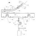
- FIG. 4is a diagram of lever arm pressure sensor.
- FIG. 5is a diagram of the electrical architecture of the control system for the ultrafiltration system.
- FIG. 6is a flow chart of the pressure control algorithm including feedback sensors and actuators under various occlusion conditions.
- FIG. 7is a flow chart of the Proportional Integral (PI) pressure control algorithm.
- FIGS. 8 a to 8 kshow diagrams of the air detector and tubing configuration.
- FIG. 1shows a schematic of the ultrafiltration system 100 .
- Withdrawal access 112 and infusion access 118are obtained to and from the vascular system of the patient 110 .
- Peripheral access via standard IV access methodsis acceptable for use with this device. This is an advantage of the device described herein, but not a limiting requirement. The device will function just as effectively with other higher flow access methods such as a fistula, central venous catheter, implanted port, midline or PICC.
- withdrawal extension 114connects proximally to withdrawal access via connectors 113 , and distally to withdrawal tubing 130 via connectors 116 .
- infusion extension 120connects proximally to infusion access via connectors 119 , and distally to infusion tubing 132 via connectors 122 .
- the withdrawal tubingmay connect directly to withdrawal access and infusion tubing directly to infusion access.
- the extensionsare optional and used for making connections and extending circuit tube lines if needed.
- a maximum blood volume of the extensionmay be specified to ensure that the maximum circuit volume is within a maximum volume so that leak detection occurs without excessive loss of blood and to avoid an excessive residence time of blood in the extracorporeal circuit.
- Withdrawal tubing 130 and infusion tubing 132both pass through or in proximity of air detector 134 , such that air bubbles can be detected in either tubing line.
- air detector 134uses ultrasound to determine the presence of air.
- An emitter and receiver of the air detectorare placed on either sides of the tubing and correctly acoustically coupled the signal transmitted between emitter and receiver and through the blood tubing. Acoustic coupling requires that a liquid be present in the tubing between the emitter and receiver. Air attenuates the signal significantly and prevents the transmission of the ultrasonic pulses thus enabling the detection of air.
- Pressure sensors 140 , 144 , 160 , 164 and 170Five different pressure sensors are employed in the described system 100 . These are pressure sensors 140 , 144 , 160 , 164 and 170 . Pressure sensors may be of the direct contact type and part of the disposable circuit, or of the indirect contact type and part of the controlling system of the pump console. Sensors need not be the same type for each location.
- the withdrawal tubingAfter passing through the air detector, the withdrawal tubing runs through withdrawal pump 142 , and then into filter 150 .
- Infusion tubing 161comes out the opposite end of the filter, travels through infusion pump 162 , and then through the air detector. Blood traveling through the filter, is treated by extraction of liquid, with the removed filtrate media exiting the filter through the ultrafiltration line 176 .
- Ultrafiltration mediatravels from the filter 150 through a blood leak sensor 172 , and then ultrafiltrate pump 174 . Ultrafiltration media is collected in a reservoir 182 by the ultrafiltrate pump 174 pump it though the tubing conduit 176 .
- An optional weight scale 180can be employed to monitor the collection of ultrafiltrate media in the reservoir. Flow rates of the infusion pump and ultrafiltrate pumps are controlled by a pump console controller so that the sum of the infusion blood flow rate and the filtrate rate equals that of the withdrawal flow rate as determined by the withdrawal pump. Pressure sensors can help monitor this flow relationship.
- Pumps 142 , 162 , and 174are reversible blood and filtration pumps, such as peristaltic roller pumps.
- the blood circuitis basically symmetrical about the filter.
- the length of the tubing line from the implanted port or catheter to the filteris equivalent to the length from the filter to the infusion catheter or implanted port.
- the first blood pump 142is connected to a first tube line 130 of the circuit
- the second blood pump 162is connected to the second tube line 132 of the circuit.
- the role of withdrawal and infusionis switched by reversing the rotational direction of the pumps. When the pumps are reversed the withdrawal access 112 is used for infusion and infusion access 118 is used for withdrawal.
- the ultrafiltration circuitis primed by connecting the withdrawal connector 116 to a saline bag and the infusion connector 122 to an ultrafiltrate reservoir 182 or some other fluid collection device.
- the peristaltic roller pumps 142 and 162operate in a clockwise direction until the tubing and filter are fully primed.
- the air detector 134senses that the tubing and filter have no air and are fully primed.
- the ultrafiltration segment 176can be primed by operating pump 174 in a clockwise direction while roller pumps 142 and 162 continue to operate in a clockwise direction. Priming of the access devices 112 , 118 and extensions 114 , 120 can be performed through connectors 116 , 122 with a syringe or other appropriate method.
- Blood pumps 142 and 162are rotated at the same speed and in the same rotational direction while ensuring that pressure 160 is positive at all times.
- the pressure in the tubingmay fall to a negative condition due to a mismatch between pump flows that can be caused by for example the tolerances of the pump velocity settings, the tolerances of the tubing diameter and other various tubing characteristics.
- the controllermay determine that the speed of pump 162 is to be increased or decreased to maintain the blood pressure in the circuit at a value or range of values such as 20 mmHg.
- the value(s)can in theory be any pressure positive or negative.
- pumps 142 and 162can operate in either a clockwise or counterclockwise direction.
- a user specified blood flow ratewill dictate how long operation can proceed in one direction before reversing.
- the length of time between pump reversalsis calculated such that, if a disconnection occurs, the maximum amount of blood which could be pumped and lost would preferably not exceed a volume of 100 milliliters (ml), and may be set to not exceed a maximum blood loss in a range of 50 ml to 200 ml.
- Q pump 142is the set blood pump flow rate
- Q pump 174is the set ultrafiltrate flow rate
- Q pump 162is the difference between the set blood pump flow rate and the set ultrafiltrate flow rate.
- Pump 174operates in a clockwise rotation during normal ultrafiltration mode. Ultrafiltration is controlled such that the filter removes a set fraction of fluid from the blood. The fraction is established to minimize any risk to the patient of excess blood concentration or to clot formation in the circuit. Pump 174 may operate in a counterclockwise rotation to backflush the filter or create some other desired pressure gradient across the filter. Since both infusion and withdrawal blood lines travel through the air detector 134 before reaching the patient, there is no risk of air entrainment reaching the patient from the blood circuit.
- the ultrafiltration pumpUpon reversal of direction of pumps 142 and 162 , the ultrafiltration pump is temporarily stopped for a set period determined based on the set blood pump flow rate, circuit volume and access volume. During this period the pump flow rates 142 and 162 are set to equal each other because the ultrafiltrate pump 174 has been stopped. The filtrate is stopped to avoid circulating blood twice through the filter. A second pass through the filter would further concentrate the blood and could increase the propensity of clots to form in the filter. The period of filtration cessation may be determined by dividing the summation of the half the volume of the extracorporeal circuit and the volume of blood in the access path (collectively the flush volume) by the blood pump flow rate. Since this flush volume is a function of the access methodology, the operator enters the flush volume into the ultrafiltration device at the time of setup.
- the ultrafiltrate rateis limited to set ultrafiltrate rate. When the ultrafiltrate pressure 170 drops below a predefined set pressure limit, the ultrafiltrate rate is reduced to maintain the target pressure using the pressure sensor 170 as feedback. This can also be used as a trigger to backflush the ultrafiltrate to clear filter fouling. For instance when the ultratiltrate rate is less than 90% of the set ultrafiltrate rate for a 1 second period the ultrafiltrate pump 174 is reversed. During this reversal it is necessary to increase the infusion pump flow to accommodate the ultrafiltrate pump flow being returned. In the case of clockwise control this will result in the pump 162 being increased to the set flow of Q pump 142 +Q pump 174 .
- pump reversalcan provide the benefit of clearing occlusions within the circuit and reducing the polarization layer which builds up within the filter fiber. Periodic pump reversals will reduce the chance of occlusions occurring within the circuit and access devices by flushing them every other cycle. If occlusions are detected by the pressure sensor, a pump reversal can be initiated prior to the normal cycle reversal in an attempt to resolve the cause of the occlusion. Such occlusions may occur due to vessel collapse, occlusion of cannulae tip or the formation of micro clots. Responding to them immediately will increase the probability of resolving the issue.
- FIG. 2is a schematic diagram of another ultrafiltration device 200 similar to the device 100 shown in FIG. 1 with the addition of an anticoagulant infusion system 203 and a position based ultrafiltrate volume limit detection system 220 .
- Bloodis withdrawn and infused through blood lines 130 and 132 .
- the bloodis withdrawn through the air detector 134 and through the filter 150 before being returned to the patient and back through the air detector 134 .
- heparin or other such anticoagulantis infused into the withdrawal line.
- the blood pressure in the withdraw linewill be negative and the pressure in the infusion line will be positive.
- the infused anticoagulantwill always infuse into the withdrawal line obviating the need for two anticoagulant pumps or some form of motor driven actuator to switch the flow of anticoagulant when blood flow is reversed. It is generally accepted that it is better to infuse an anticoagulant upstream of the filter because the filter is in the extracorporeal circuit and has a high likelihood for initiating the clotting cascade. Infusing the anticoagulant upstream facilitates a high concentration of anticoagulant locally within the circuit and filter while minimizing systemic anticoagulation.
- the anticoagulation pump 304is a syringe pump. Flows from syringe pumps are typically in the order of 0 to 20 ml/hr ranging from drug delivery flow rates of 0 to 1000 units/hr when heparin is used as the anticoagulant in hemofiltration. Since this ultrafiltration device has considerably lower blood flows, a much lower flow range of 0 to 2 ml/hr will suffice facilitating a much smaller syringe pump design.
- the syringe pump 304delivers anticoagulant via the T connector 203 through two possible paths 208 or 209 .
- T connector 203is connected to the one way valve 202 via a conduit tube 209 and to one way valve 207 via a conduit tube 208 .
- One way valve 203is connected to T connector 201 via a conduit tube and one way valve 207 is connected to T connector 206 via a conduit tube.
- the ultrafiltrate removed from the filter 150 by the ultrafiltrate pump 174is withdrawn passed the blood leak detector 172 and pumped into the collection reservoir 224 via the conduit tube 176 .
- the blood leak detector 172uses a near infra red (IR) photo emitter and receiver with a peak sensitivity close to the isospectic point of blood, 820 nm. In the presence of ultrafiltrate and saline little or no attenuation of the IR signal occurs but in the presence of blood the IR signal is dispersed and greatly attenuated making it possible to measure the presence of blood in ultrafiltrate. Blood in the ultrafiltrate indicates a breach of the filter membrane and when detected, causes the pumps to stop.
- IRnear infra red
- the reservoir bagis compressed by spring 226 and plate 223 .
- the reservoirexpands and the spring compresses.
- the bag switch 221 arm 225is intercepted by the spring plate 223 the switch is opened indicating that the bag is fully.
- the ultrafiltrate pumpis stopped and the user is informed via an alarm that the bag has to be emptied.
- the bagis designed to hold 250 ml.
- the switch 221is connected electrically to the system processor via cable 222 .
- the springcreates a maximum pressure in tube 176 of 2 to 5 psi.
- Blood circuit peristaltic pumpshave been designed to relieve at pressures exceeding 60 psi.
- a proximity switchmay also be used instead of a mechanical switch. The advantage of a mechanical switch is that it consumes no energy.
- the reservoir 224may be emptied via the stopcock 240 .
- Ultrafiltrationoccurs inside the filter 150 .
- Whole bloodenters the bundle of hollow fibers from the cap of the filter canister. There are approximately 160 hollow fibers in the bundle, and each fiber is a filter. Blood flows through a channel approximately 0.2 mm in diameter in each fiber. The fiber walls of the channel are made of a porous material. The pores are permeable to water and small solutes but impermeable to red blood cells, proteins and other blood components that are larger than 50,000-60,000 Daltons. Blood flow in fibers is tangential to the surface of the filter membrane. The shear rate resulting from the blood velocity is high enough such that the pores in the membrane are protected from fouling by particles, allowing the filtrate to permeate the fiber wall. Filtrate (ultrafiltrate) leaves the fiber bundle and is collected in a space between the inner wall of the filter canister and outer walls of the fibers.
- the geometry of the filteris optimized to prevent clotting and fouling of the membrane.
- the active area of the filter membraneis approximately 0.023 m 2 .
- the permeability KUF of the membraneis 30 to 33 mL/hour/m 2 /mmHg. These parameters allow the desired ultrafiltration rate of approximately 1 liter to 3 liters every 24 hrs at the TMP of 150 to 250 mmHg that is generated by the resistance to flow.
- the effective filter lengthis 22.5 cm and the diameter of the filter fiber bundle is 0.5 cm.
- the blood shear rate in the filtermay be 850 to 2500 sec-1 at blood flow rate of 5 to 15 mL/min.
- the return 132 and withdrawal 130 tubingmay be 60 cm in length. With a tubing diameter of 2.5 mm the volume in the complete circuit blood path is less than 7 mL. With a tubing diameter of 2 mm the volume in the complete circuit blood path is less than 5 mL. Minimizing this volume reduces the blood residence time of the devices propensity to clot.
- FIG. 3shows a diagram of the apparatus worn by a patient as described in FIG. 2 .
- the ultrafiltration devicemay be attached to a waist belt worn by the patient 300 or over the shoulder or on the back of the patient to provide ambulatory use of the device.
- Access to the patient bloodis depicted by 301 via an implanted port with its cannulae placed centrally.
- Withdrawal and infusion blood lines 132 and 130exit from the patient access site 301 and are connected to the ultrafiltration device 304 and 303 at the back of the patient.
- the console 304includes a liquid crystal display (LCD) 305 and a membrane panel for viewing and entering patient therapy parameters.
- the reservoir 308is separate from the console and is connected to the console via the electrical cable 309 and the ultrafiltrate conduit tube 176 .
- LCDliquid crystal display
- the reservoirseparate minimizes weight accumulation on a specific area and also reduces the hazard of wetting the console.
- Additional battery packsmay also be stored on the belt and may be connected directly to the ultrafiltrate device as needed.
- the consoleannunciates an alarm requesting the user to empty the ultrafiltrate reservoir.
- a reservoirmay be disconnected and emptied or drained using an extension hose connected to the reservoir minimizing the potential for spill on the patients clothing.
- FIG. 4shows a detailed view of the cantilevered pressure transducer assembly 400 used for measuring pressures at sites 140 , 144 , 160 , 164 and 172 shown in FIG. 2 .
- the userinserts the tubing into the recess defined by the lever arm strain gauge 401 and the housing body 402 .
- the lever arm strain gauge 401is attached to the housing by a securing screw 301 .
- the circuit tubing 403which is normally cylindrical in shape is deformed to an oval shape by the insertion of the tube into the pressure transducer recess defined by 401 and 402 .
- the lever arms 401 central axis 404is depicted in FIG. 4 when atmospheric pressure is present within the circuit tube and when a positive pressure 405 is present within the tube.
- the lever arm 401is bent upwards such that the central axis 405 when pressure is positive and bent downwards when pressure is negative.
- the strain gaugeconsists of a Wheatstone bridge resistor network on the lever arm and changes in resistance in proportion to the pressure exerted by the circuit tube. This is interpreted as an electrical signal when the transducer is excited electrically via 2 excitation wires of the 4 wire electrical cable 406 .
- the ultrafiltration devicedoes not need pressure sensors for the detection of disconnects, a similar approach to that used to measure pressure used by standard infusion pumps may be employed.
- the expansion of the blood linesis used to monitor for the detection of occlusions by use of force gauges which convert the force exerted by the blood and ultrafiltrate tubing to an electrical signal.
- the force gaugemay be a load cell similar to that sold by SMD (Strain Measurement Devices) of Meriden, Conn. and St. Edmunds, England.
- the load cellmay include a lever arm that applies pressure to the tubing by compressing it slightly.
- the measured pressurecan be zeroed mathematically by the pump console microprocessor to remove offsets due to tubing position.
- the tubeexpands against the load cell lever arm raising the lever arm producing an electrical signal proportional to the pressure in the tube.
- the tubecollapses and thereby lowers the lever arm create an electrical signal proportional to the pressure in the tube.
- Peristaltic pump tubingrequires that the tubing be flexible and compliant, i.e. of low durometer, otherwise the torque required to compress the tubing is excessive. It is possible to use different materials for each section of the circuit but this will create additional joints decreasing the reliability of the blood circuit. It is difficult to reliably bond different polymers materials to each other and such a construction creates an added hazard for disconnects and leaks. It is also helpful to minimize the number of transitions and joints in the circuit be minimized to decrease the circuits clotting propensity and improve circuit reliability.
- FIG. 5shows a diagram of the electrical architecture of the ultrafiltration device consisting of the console 305 and reservoir 308 .
- the console 304houses the LCD 305 , membrane panel 306 , blood leak detector 172 , pressure sensors 140 , 144 , 170 , 160 and 164 , battery pack 506 , blood pumps 142 and 162 , ultrafiltrate pump 174 , syringe pump 508 , alarm speaker 508 and main printed circuit board (PCB) 502 .
- PCBmain printed circuit board
- main PC 502there are 3 processors, the main central processor (CP) 503 , the pump motor control (MC) CP 504 and the safety CP 505 .
- Each of the sensor readings including blood leak, air detector, pump encoders and pressure sensorsare shared between the main CP and the safety CP facilitating a control and monitor implementation for system safety.
- the pumps motorsare each driven by a brushless DC motor and electrically commutated by the MC CP using encoder feedback and 1 ⁇ 2 bridge circuit on the PCB 502 .
- Each motorhas a quadrature encoder which outputs A and B quadrature digital signals as the motor is rotated as a function of motor position.
- Each motoris geared for optimal efficiency with a gear ratio of 10:1 resulting in a peak power consumption of less than 2 watts per motor.
- the pressure sensorsblood leak detector and air detector are only powered when it is necessary to read the sensor signal.
- the digital sample rate for the console sensorsis 50 Hz.
- the console battery packoperates at 12 VDC and uses NiMH chemistry. Charging of the batteries is performed off line with a separate battery charger. This reduces the electrical circuitry required during operation and minimizes power consumption and space requirements.
- Use of an external power sourceis possible via and external power supply with an output of 12 VDC. The battery supply is disabled when an external power supply is connected.
- the reservoir 308is connected electrically via a 2 wire cable to the console 304 providing electrical connection for the reservoirs expansion limit mechanical switch 221 .
- the mechanical switch 221is normally closed until the reservoir is full. When full the switch is thrown open providing the additional safety that if the electrical cable were to become disconnected ultrafiltration would be stopped.
- the main CPreads each of the pressure inputs and updates the blood and ultrafiltrate pumps velocity every 20 ms.
- the liquid crystal display (LCD)is only powered if it has a message to display or if the operator presses a membrane panel key.
- the consoleduty cycles a green light emitting diode (LED) every second to indicate that it is operating correctly. In the event of a problem, a red LED is flashed and an alarm annunciated via the speaker.
- the LCDis then powered on and displays a message informing the users of the potential cause of the issue and remedy.
- FIG. 6shows a flow chart of which pressure sensors the ultrafiltration device uses for feedback when in clockwise or anticlockwise blood pump rotation and which pumps it uses to control these pressures to limit pressure excursions.
- Four pressure control loopsare operating simultaneously. These loops are: (i) the withdrawal pressure control algorithm, (ii) the infusion pressure control algorithm, (iii) the filter positive pressure control algorithm and (iv) the ultrafiltrate pressure control algorithm
- Pxfeedback and Qxcontrolare used where P denotes pressure, Q flow of pump, x the control algorithm i.e. w withdrawal, i infusion, c filter pressure or center pressure and u ultrafiltrate.
- the same feedback pressure sensor 160is used as shown in blocks 610 and 611 but the control pump is changed from 162 to 142 . This eliminates any conflict between which pump is used for control while still maintaining both pressure targets.
- the withdrawal and infusion pressure targets read by pressure sensors 140 and 160 respectivelyare ⁇ 300 and 300 mmHg respectively.
- the blood pump flowsare limited by the user defined set blood pump flow which is set to be as high as possible based upon the available access minimizing blood circuit residence time and maximizing the maximum rates of ultrafiltration. The maximum extraction rate of ultrafiltrate is limited to 21% of blood flow. If an infusion occlusion is persistent for an extended period of time then the direction of the blood pumps are reversed. Blood pump reversals are normally timed based and are a function of set blood pump flow but in the vent of a persistent occlusion in either the withdrawal or infusion line the reversal sequence may be initiated early.
- the pressure sensor 140is used as feedback and the blood pump 142 is used as control as shown in block 604 .
- the same feedback pressure sensor 144is used as shown in blocks 605 and 606 but the control pump is changed from 142 to 162 . This eliminates any conflict between which pump is used for control while still maintaining both pressure targets.
- Block 612shows that the pressure sensor 174 and ultrafiltrate pump 174 are unaffected by blood pump direction.
- FIG. 7shows how the pressure control loop 700 is implemented. This pressure control loop is used for all four control loop described in FIG. 6 .
- the difference between the target pressure 700 and the feedback pressure 705 , the pressure errorare input to a PI (Proportional Integral) control loop 703 .
- PIProportional Integral
- the integration term of the PI loopis set to 0 ml and is limited to +/ ⁇ 20% of the set blood flow rate to prevent windup of the integrator.
- the blood flowis set to 10 ml/min the maximum the integration term if allowed to sum to is +/ ⁇ 1 ml/min when trying to the pressure sensor 160 to the target pressure P target .
- the +/ ⁇ 20% limitis chosen because the blood pump has an accuracy of +/ ⁇ 10% and variations significantly above of below this imply a fault condition.
- the resultant pump flow of the summed PI output and the FF termis commanded by the MC CP to the pump 703 which delivers the desired fluid flow and results in a circuit 704 causing the pressure 705 due to the circuit and access resistance.
- This pressure 705is read by the Main CP using an ADC (Analog to Digital Convertor) and is used to calculate the pressure error by subtracting the feedback pressure 705 from the target pressure 701 .
- ADCAnalog to Digital Convertor
- FIGS. 8 a to 8 kare diagrams depicting the air detector and cross-sections of the withdrawal and return tube passing through the air detector.
- the dual lumen tube designeliminates the need for a second air detector and also reduces the power consumption requirements for the device. This minimizes the required space, weight and battery capacity for device operation.
- the air detector 801uses an ultrasonic emitter 802 and receiver 803 .
- the withdrawal 802 and return tube 804are inserted into the air detector slot and as long as the lumens are full of liquid no air detection will be detected. If a bubble of gas is entrained into the withdrawal of return tube, passes through the air detector and is greater than 50 microliters in volume, an air detected alarm is annunciated by the console.
- the signal strength received by the receiverwill dramatically reduce in the presence of an air bubble because a gas is significantly less dense than a liquid and there are large losses in the energy being transmitted making the detection of bubbles possible. This will be interpreted as an air detected alarm by the ultrafiltration device.
- FIGS. 8 b to 8 kshow the many combinations of tubing cross-section supporting dual, triple and multiple lumens which will support such an air detection implementation.
- the patient circuit tubingis inserted into the air detector slot during the priming sequence of the ultrafiltration device.
- FIG. 8 bshows a dual oval shaped co-extruded cross-section. It would also possible to make such a portion of tubing by gluing two tubes together to facilitate.
- FIGS. 8 c and 8 dshow an hour glass dual circular co-extruded cross-section in both the horizontal and vertical position demonstrating orientation is not important when inserting the tubing segment into the air detector for the purposes of detecting air.
- Such a cross-sectioncould be extruded or be formed from gluing two tubes together as part of the circuit manufacturing process. Either extruding or gluing will enable a similar cross-section.
- the cross-section of the two lumen tubingis also not limited to being hour glass shaped, it may be square in shape as shown in FIG.
- FIG. 8 eshows circular with two inner D lumen as shown in FIG. 8 f or a combination of two lumen shapes ranging from circular and oval to kidney shaped as shown in FIG. 8 g .
- FIG. 8 hshows a co-extruded concentric tubing cross-section which will also work. Air in either channel will result in an air detection alarm.
- FIG. 8 kshows a double oval lumen implementation of a dual lumen tubing implementation. The purpose of showing these configurations is to demonstrate that the implementation is not limited to a specific tubular configuration and that many implementations are feasible.
- FIG. 8 ishows a three lumen implementation using a square profile.
- FIG. 8 jshows a similar three lumen implementation using a circular lumen profile.
- the detection methodwill work with multiple lumens as shown in FIGS. 8 b to 8 k.
Landscapes
- Health & Medical Sciences (AREA)
- Heart & Thoracic Surgery (AREA)
- Engineering & Computer Science (AREA)
- Veterinary Medicine (AREA)
- General Health & Medical Sciences (AREA)
- Anesthesiology (AREA)
- Biomedical Technology (AREA)
- Hematology (AREA)
- Life Sciences & Earth Sciences (AREA)
- Animal Behavior & Ethology (AREA)
- Public Health (AREA)
- Cardiology (AREA)
- Vascular Medicine (AREA)
- Mechanical Engineering (AREA)
- Urology & Nephrology (AREA)
- Medical Informatics (AREA)
- Pulmonology (AREA)
- Emergency Medicine (AREA)
- External Artificial Organs (AREA)
Abstract
Description
thereforeQpump 162=Qpump 142−
TMP=((P144+P160)/2)−P170
FF=
Claims (12)
Priority Applications (6)
| Application Number | Priority Date | Filing Date | Title |
|---|---|---|---|
| US11/002,442US7615028B2 (en) | 2004-12-03 | 2004-12-03 | Extracorporeal blood treatment and system having reversible blood pumps |
| DE200560017002DE602005017002D1 (en) | 2004-12-03 | 2005-12-02 | System for extracorporeal blood treatment with reversible blood pumps |
| EP20050026347EP1666078B1 (en) | 2004-12-03 | 2005-12-02 | Extracorporeal blood treatment system having reversible blood pumps |
| AT05026347TATE444770T1 (en) | 2004-12-03 | 2005-12-02 | SYSTEM FOR EXTRACORPORAL BLOOD TREATMENT USING REVERSIBLE BLOOD PUMPS |
| US12/613,588US8475398B2 (en) | 2004-12-03 | 2009-11-06 | Extracorporeal blood treatment and system having reversible blood pumps |
| US13/904,358US9089653B2 (en) | 2004-12-03 | 2013-05-29 | Extracorporeal blood treatment and system having reversible blood pumps |
Applications Claiming Priority (1)
| Application Number | Priority Date | Filing Date | Title |
|---|---|---|---|
| US11/002,442US7615028B2 (en) | 2004-12-03 | 2004-12-03 | Extracorporeal blood treatment and system having reversible blood pumps |
Related Child Applications (1)
| Application Number | Title | Priority Date | Filing Date |
|---|---|---|---|
| US12/613,588DivisionUS8475398B2 (en) | 2004-12-03 | 2009-11-06 | Extracorporeal blood treatment and system having reversible blood pumps |
Publications (2)
| Publication Number | Publication Date |
|---|---|
| US20060122552A1 US20060122552A1 (en) | 2006-06-08 |
| US7615028B2true US7615028B2 (en) | 2009-11-10 |
Family
ID=35925170
Family Applications (3)
| Application Number | Title | Priority Date | Filing Date |
|---|---|---|---|
| US11/002,442Expired - Fee RelatedUS7615028B2 (en) | 2004-12-03 | 2004-12-03 | Extracorporeal blood treatment and system having reversible blood pumps |
| US12/613,588Expired - Fee RelatedUS8475398B2 (en) | 2004-12-03 | 2009-11-06 | Extracorporeal blood treatment and system having reversible blood pumps |
| US13/904,358Expired - Fee RelatedUS9089653B2 (en) | 2004-12-03 | 2013-05-29 | Extracorporeal blood treatment and system having reversible blood pumps |
Family Applications After (2)
| Application Number | Title | Priority Date | Filing Date |
|---|---|---|---|
| US12/613,588Expired - Fee RelatedUS8475398B2 (en) | 2004-12-03 | 2009-11-06 | Extracorporeal blood treatment and system having reversible blood pumps |
| US13/904,358Expired - Fee RelatedUS9089653B2 (en) | 2004-12-03 | 2013-05-29 | Extracorporeal blood treatment and system having reversible blood pumps |
Country Status (4)
| Country | Link |
|---|---|
| US (3) | US7615028B2 (en) |
| EP (1) | EP1666078B1 (en) |
| AT (1) | ATE444770T1 (en) |
| DE (1) | DE602005017002D1 (en) |
Cited By (25)
| Publication number | Priority date | Publication date | Assignee | Title |
|---|---|---|---|---|
| US20080195021A1 (en)* | 2007-02-09 | 2008-08-14 | Baxter International Inc. | Acoustic access disconnection systems and methods |
| US7927544B2 (en) | 2005-04-21 | 2011-04-19 | Alung Technologies, Inc. | Paracorporeal respiratory assist lung |
| US20140110319A1 (en)* | 2011-06-15 | 2014-04-24 | The Newcastle Upon Tyne Hospitals Nhs Foundation Trust | Apparatus for performing haemodialysis |
| US9072843B2 (en) | 2003-11-05 | 2015-07-07 | Baxter International Inc. | Renal therapy system having pump reversing fluid control |
| US9383288B2 (en) | 2008-06-26 | 2016-07-05 | Gambro Lundia Ab | Method and device for processing a time-dependent measurement signal |
| US9433356B2 (en) | 2009-06-26 | 2016-09-06 | Gambro Lundia Ab | Devices, a computer program product and a method for data extraction |
| US9895109B2 (en) | 2013-03-20 | 2018-02-20 | Gambro Lundia Ab | Monitoring of cardiac arrest in a patient connected to an extracorporeal blood processing apparatus |
| US10413654B2 (en) | 2015-12-22 | 2019-09-17 | Baxter International Inc. | Access disconnection system and method using signal metrics |
| US10463778B2 (en) | 2007-02-09 | 2019-11-05 | Baxter International Inc. | Blood treatment machine having electrical heartbeat analysis |
| US10980431B2 (en) | 2009-12-28 | 2021-04-20 | Gambro Lundia Ab | Apparatus and method for prediction of rapid symptomatic blood pressure decrease |
| US11033670B2 (en) | 2010-07-07 | 2021-06-15 | Deka Products Limited Partnership | Medical treatment system and methods using a plurality of fluid lines |
| US11033671B2 (en) | 2011-05-24 | 2021-06-15 | Deka Products Limited Partnership | Systems and methods for detecting vascular access disconnection |
| US11529444B2 (en) | 2007-02-27 | 2022-12-20 | Deka Products Limited Partnership | Blood treatment systems and methods |
| US11568043B2 (en) | 2007-02-27 | 2023-01-31 | Deka Products Limited Partnership | Control systems and methods for blood or fluid handling medical devices |
| US11725645B2 (en) | 2006-04-14 | 2023-08-15 | Deka Products Limited Partnership | Automated control mechanisms and methods for controlling fluid flow in a hemodialysis apparatus |
| US11752248B2 (en) | 2008-01-23 | 2023-09-12 | Deka Products Limited Partnership | Medical treatment system and methods using a plurality of fluid lines |
| US11752244B2 (en) | 2007-02-27 | 2023-09-12 | Deka Products Limited Partnership | Blood circuit assembly for a hemodialysis system |
| US20230310726A1 (en)* | 2019-09-06 | 2023-10-05 | Adventist Health System/Sunbelt, Inc. | Advanced dialysis catheter with pressure sensor |
| US11793915B2 (en) | 2007-02-27 | 2023-10-24 | Deka Products Limited Partnership | Hemodialysis systems and methods |
| US11833281B2 (en) | 2008-01-23 | 2023-12-05 | Deka Products Limited Partnership | Pump cassette and methods for use in medical treatment system using a plurality of fluid lines |
| US11890403B2 (en) | 2011-05-24 | 2024-02-06 | Deka Products Limited Partnership | Hemodialysis system |
| US12026271B2 (en) | 2014-05-27 | 2024-07-02 | Deka Products Limited Partnership | Control systems and methods for blood or fluid handling medical devices |
| US12171922B2 (en) | 2008-08-27 | 2024-12-24 | Deka Products Limited Partnership | Blood treatment systems and methods |
| US12194213B2 (en) | 2011-11-04 | 2025-01-14 | Deka Products Limited Partnership | Medical treatment system and methods using a plurality of fluid lines |
| US12303631B2 (en) | 2011-11-04 | 2025-05-20 | Deka Products Limited Partnership | Medical treatment system and methods using a plurality of fluid lines |
Families Citing this family (106)
| Publication number | Priority date | Publication date | Assignee | Title |
|---|---|---|---|---|
| WO2003086509A1 (en) | 2002-04-11 | 2003-10-23 | Deka Products Limited Partnership | System and method for delivering a target volume of fluid |
| US7615028B2 (en) | 2004-12-03 | 2009-11-10 | Chf Solutions Inc. | Extracorporeal blood treatment and system having reversible blood pumps |
| US8092414B2 (en) | 2005-11-09 | 2012-01-10 | Nxstage Medical, Inc. | Diaphragm pressure pod for medical fluids |
| JP4798653B2 (en) | 2005-11-18 | 2011-10-19 | 日機装株式会社 | Blood purification equipment |
| US9717834B2 (en) | 2011-05-24 | 2017-08-01 | Deka Products Limited Partnership | Blood treatment systems and methods |
| US8393690B2 (en) | 2007-02-27 | 2013-03-12 | Deka Products Limited Partnership | Enclosure for a portable hemodialysis system |
| US8491184B2 (en) | 2007-02-27 | 2013-07-23 | Deka Products Limited Partnership | Sensor apparatus systems, devices and methods |
| US8105487B2 (en) | 2007-09-25 | 2012-01-31 | Fresenius Medical Care Holdings, Inc. | Manifolds for use in conducting dialysis |
| US8535522B2 (en) | 2009-02-12 | 2013-09-17 | Fresenius Medical Care Holdings, Inc. | System and method for detection of disconnection in an extracorporeal blood circuit |
| US8240636B2 (en) | 2009-01-12 | 2012-08-14 | Fresenius Medical Care Holdings, Inc. | Valve system |
| US8475399B2 (en) | 2009-02-26 | 2013-07-02 | Fresenius Medical Care Holdings, Inc. | Methods and systems for measuring and verifying additives for use in a dialysis machine |
| US9358331B2 (en) | 2007-09-13 | 2016-06-07 | Fresenius Medical Care Holdings, Inc. | Portable dialysis machine with improved reservoir heating system |
| US8597505B2 (en) | 2007-09-13 | 2013-12-03 | Fresenius Medical Care Holdings, Inc. | Portable dialysis machine |
| US9308307B2 (en) | 2007-09-13 | 2016-04-12 | Fresenius Medical Care Holdings, Inc. | Manifold diaphragms |
| US20090101577A1 (en)* | 2007-09-28 | 2009-04-23 | Fulkerson Barry N | Methods and Systems for Controlling Ultrafiltration Using Central Venous Pressure Measurements |
| US8040493B2 (en) | 2007-10-11 | 2011-10-18 | Fresenius Medical Care Holdings, Inc. | Thermal flow meter |
| US20090076434A1 (en)* | 2007-09-13 | 2009-03-19 | Mischelevich David J | Method and System for Achieving Volumetric Accuracy in Hemodialysis Systems |
| US8114276B2 (en)* | 2007-10-24 | 2012-02-14 | Baxter International Inc. | Personal hemodialysis system |
| CA3057807C (en) | 2007-11-29 | 2021-04-20 | Thomas P. Robinson | System and method for conducting hemodialysis and hemofiltration |
| DE102008004977A1 (en)* | 2008-01-17 | 2009-07-23 | Miltenyi Biotec Gmbh | Device for the removal of biological material |
| JP5595930B2 (en) | 2008-01-23 | 2014-09-24 | デカ・プロダクツ・リミテッド・パートナーシップ | Disposable components for fluid line automatic connection systems |
| US20100184198A1 (en)* | 2009-01-16 | 2010-07-22 | Joseph Russell T | Systems and Methods of Urea Processing to Reduce Sorbent Load |
| US8535253B2 (en) | 2008-09-30 | 2013-09-17 | Covidien Lp | Tubeless compression device |
| EP3586946B1 (en) | 2008-10-07 | 2023-03-29 | Fresenius Medical Care Holdings, Inc. | Priming system and method for dialysis systems |
| EA024555B1 (en) | 2008-10-30 | 2016-09-30 | Фрезениус Медикал Кеа Холдингс, Инк. | Modular, portable dialysis system |
| JP5345373B2 (en)* | 2008-11-28 | 2013-11-20 | 旭化成メディカル株式会社 | Blood extracorporeal circulation device and method of operating the blood extracorporeal circulation device |
| WO2010114932A1 (en) | 2009-03-31 | 2010-10-07 | Xcorporeal, Inc. | Modular reservoir assembly for a hemodialysis and hemofiltration system |
| CN104841030B (en) | 2009-10-30 | 2017-10-31 | 德卡产品有限公司 | For the apparatus and method for the disconnection for detecting intravascular access device |
| US8753515B2 (en) | 2009-12-05 | 2014-06-17 | Home Dialysis Plus, Ltd. | Dialysis system with ultrafiltration control |
| ES2539821T3 (en) | 2009-12-28 | 2015-07-06 | Gambro Lundia Ab | Control of an apparatus for fluid transfer to and / or from a subject |
| US8394043B2 (en) | 2010-02-12 | 2013-03-12 | Covidien Lp | Compression garment assembly |
| US9555174B2 (en) | 2010-02-17 | 2017-01-31 | Flow Forward Medical, Inc. | Blood pump systems and methods |
| US9662431B2 (en) | 2010-02-17 | 2017-05-30 | Flow Forward Medical, Inc. | Blood pump systems and methods |
| KR101845213B1 (en)* | 2010-02-17 | 2018-05-18 | 플로우 포워드 메디컬, 인크. | System and method to increase the overall diameter of veins |
| US8501009B2 (en) | 2010-06-07 | 2013-08-06 | State Of Oregon Acting By And Through The State Board Of Higher Education On Behalf Of Oregon State University | Fluid purification system |
| GB2498124A (en)* | 2010-09-23 | 2013-07-03 | Nxstage Medical Inc | Pressure sensing methods, devices, and systems |
| GB2505363B (en) | 2011-05-12 | 2014-10-22 | Nxstage Medical Inc | Fluid heating apparatuses, systems and methods |
| US9551625B2 (en) | 2011-05-31 | 2017-01-24 | Nxstage Medical, Inc. | Pressure measurement devices, methods, and systems |
| CN103889481B (en) | 2011-08-02 | 2016-03-09 | 美敦力公司 | Hemodialysis system with flow path with controlled compliance volume |
| KR102062132B1 (en) | 2011-08-17 | 2020-01-03 | 플로우 포워드 메디컬, 인크. | Blood pump systems and methods |
| EP2744539B1 (en) | 2011-08-17 | 2022-11-02 | Artio Medical, Inc. | System to increase the overall diameter of a peripheral artery |
| JP2014533133A (en) | 2011-10-07 | 2014-12-11 | ホーム・ダイアリシス・プラス・リミテッドHome DialysisPlus, Ltd. | Purification of heat exchange fluids for dialysis systems |
| US10258730B2 (en) | 2012-08-17 | 2019-04-16 | Flow Forward Medical, Inc. | Blood pump systems and methods |
| JP5469728B1 (en)* | 2012-10-19 | 2014-04-16 | 日機装株式会社 | Liquid channel pressure detector |
| JP5587958B2 (en)* | 2012-10-19 | 2014-09-10 | 日機装株式会社 | Ironing type pump |
| EP2737918B1 (en)* | 2012-11-29 | 2016-06-01 | Gambro Lundia AB | Hemodialysis on-line port leak detection |
| US9201036B2 (en) | 2012-12-21 | 2015-12-01 | Fresenius Medical Care Holdings, Inc. | Method and system of monitoring electrolyte levels and composition using capacitance or induction |
| US9157786B2 (en) | 2012-12-24 | 2015-10-13 | Fresenius Medical Care Holdings, Inc. | Load suspension and weighing system for a dialysis machine reservoir |
| WO2014105517A1 (en)* | 2012-12-31 | 2014-07-03 | Gambro Renal Products, Inc. | Extracorporeal blood treatment data interface |
| US11154648B2 (en) | 2013-01-09 | 2021-10-26 | Medtronic, Inc. | Fluid circuits for sorbent cartridge with sensors |
| US9713666B2 (en) | 2013-01-09 | 2017-07-25 | Medtronic, Inc. | Recirculating dialysate fluid circuit for blood measurement |
| US10010663B2 (en) | 2013-02-01 | 2018-07-03 | Medtronic, Inc. | Fluid circuit for delivery of renal replacement therapies |
| US9623164B2 (en) | 2013-02-01 | 2017-04-18 | Medtronic, Inc. | Systems and methods for multifunctional volumetric fluid control |
| US10850016B2 (en) | 2013-02-01 | 2020-12-01 | Medtronic, Inc. | Modular fluid therapy system having jumpered flow paths and systems and methods for cleaning and disinfection |
| US9433720B2 (en) | 2013-03-14 | 2016-09-06 | Fresenius Medical Care Holdings, Inc. | Universal portable artificial kidney for hemodialysis and peritoneal dialysis |
| US20140263062A1 (en) | 2013-03-14 | 2014-09-18 | Fresenius Medical Care Holdings, Inc. | Universal portable machine for online hemodiafiltration using regenerated dialysate |
| US9327099B2 (en) | 2013-06-04 | 2016-05-03 | Spectrum Health Innovations, LLC | Medical tube harness |
| US9354640B2 (en)* | 2013-11-11 | 2016-05-31 | Fresenius Medical Care Holdings, Inc. | Smart actuator for valve |
| US10537875B2 (en) | 2013-11-26 | 2020-01-21 | Medtronic, Inc. | Precision recharging of sorbent materials using patient and session data |
| US9884145B2 (en) | 2013-11-26 | 2018-02-06 | Medtronic, Inc. | Parallel modules for in-line recharging of sorbents using alternate duty cycles |
| US10905818B2 (en) | 2014-03-31 | 2021-02-02 | Zoll Medical Corporation | Blood filtering of inflammatory biomarkers to treat post-resuscitation syndrome |
| JP5863871B2 (en) | 2014-04-15 | 2016-02-17 | 日機装株式会社 | Mounting member and ironing pump |
| EP3838308A1 (en)* | 2014-04-29 | 2021-06-23 | Outset Medical, Inc. | Dialysis system and methods |
| WO2015199768A1 (en) | 2014-06-24 | 2015-12-30 | Medtronic, Inc. | Stacked sorbent assembly |
| ES2989503T3 (en) | 2014-06-24 | 2024-11-26 | Mozarc Medical Us Llc | Modular dialysate regeneration assembly |
| DE102014119445A1 (en)* | 2014-12-22 | 2016-06-23 | Fresenius Medical Care Deutschland Gmbh | An infusion line having means for facilitating mixing of an infusion solution with another fluid, devices and methods |
| JP5986258B1 (en)* | 2015-04-20 | 2016-09-06 | 日機装株式会社 | Blood purification equipment |
| EP3315150B1 (en) | 2015-06-24 | 2020-12-09 | Nikkiso Co., Ltd. | Blood purifying device |
| US20170049959A1 (en) | 2015-08-20 | 2017-02-23 | Sorrel Medical Ltd. | Automatic Catheter Recognition and Associated Methods, Systems and Circuits |
| EP3744366B1 (en)* | 2015-12-21 | 2023-10-04 | Fresenius Medical Care Holdings, Inc. | Modular blood treatment systems and units |
| AU2017257508B2 (en) | 2016-04-29 | 2021-10-14 | Artio Medical, Inc. | Conduit tips and systems and methods for use |
| JP6595123B2 (en) | 2016-05-25 | 2019-10-23 | ムーグ インコーポレイテッド | Detection system for multi-lumen tubes |
| EP3500317B1 (en) | 2016-08-19 | 2022-02-23 | Outset Medical, Inc. | Peritoneal dialysis system and methods |
| DE102016117974A1 (en) | 2016-09-23 | 2018-03-29 | Fresenius Medical Care Deutschland Gmbh | Insert for a blood tubing set to facilitate mixing of an infusion solution with another fluid |
| CN109803696B (en) | 2016-10-03 | 2022-08-05 | 甘布罗伦迪亚股份公司 | Measuring channel flow rate by using a blood processing machine |
| MA39440A1 (en)* | 2016-11-07 | 2018-05-31 | Univ Hassan Ii De Casablanca | Portable ultrafiltration device |
| US20200054818A1 (en)* | 2016-11-10 | 2020-02-20 | Dexerials Corporation | Fluid system, medical system, sensor, circuit conduit member, attachment jig, and attachment method |
| US10981148B2 (en) | 2016-11-29 | 2021-04-20 | Medtronic, Inc. | Zirconium oxide module conditioning |
| EP3329948B1 (en)* | 2016-12-01 | 2023-09-06 | Fenwal, Inc. | Blood component pooling device, system and method |
| WO2018151084A1 (en)* | 2017-02-20 | 2018-08-23 | テルモ株式会社 | Pressure sensor and extracorporeal circulation apparatus |
| US10960381B2 (en) | 2017-06-15 | 2021-03-30 | Medtronic, Inc. | Zirconium phosphate disinfection recharging and conditioning |
| EP3421061A1 (en) | 2017-06-28 | 2019-01-02 | Fresenius Medical Care Deutschland GmbH | Another insert piece for a blood tubing set to promote mixing an infusion solution with a further fluid |
| CN110809802B (en) | 2017-06-28 | 2024-06-18 | 甘布罗伦迪亚股份公司 | Systems and methods for kidney replacement therapy |
| JP6464238B1 (en) | 2017-09-07 | 2019-02-06 | 日機装株式会社 | Blood purification apparatus and method for discharging bubbles |
| JP6462077B1 (en) | 2017-09-07 | 2019-01-30 | 日機装株式会社 | Blood purification apparatus and method for discharging bubbles |
| US10946126B2 (en)* | 2017-10-04 | 2021-03-16 | University Of Louisiana At Lafayette | Electrocardiography triggered piston pump |
| EP3749387A4 (en) | 2018-02-11 | 2021-11-10 | Eitan Medical Ltd. | INFUSION PUMP WITH FLEXIBLE STROKE |
| CN108795692B (en)* | 2018-06-26 | 2021-01-01 | 成都普瑞康生物科技有限公司 | Rare cell capture system and application thereof |
| US12285552B2 (en) | 2018-08-14 | 2025-04-29 | Mozarc Medical Us Llc | Precision dialysis therapy based on sorbent effluent analysis |
| US12201762B2 (en) | 2018-08-23 | 2025-01-21 | Outset Medical, Inc. | Dialysis system and methods |
| AU2019343148A1 (en)* | 2018-09-19 | 2021-02-18 | Fresenius Medical Care Deutschland, Gmbh | Techniques for dialysis based on relative blood volume |
| TR201819907A2 (en)* | 2018-12-20 | 2019-01-21 | Canakkale Onsekiz Mart Ueniversitesi Rektoerluegue | PORTABLE WEAR HEMODIALYSIS SYSTEM |
| EP3866733A4 (en)* | 2018-12-31 | 2021-12-15 | Nuwellis, Inc. | PORTABLE ARMREST FOR BLOOD FLOW SUPPORT |
| IL273061B2 (en) | 2019-03-04 | 2024-01-01 | Avoset Health Ltd | In cycle pressure measurement |
| ES2989157T3 (en) | 2019-03-05 | 2024-11-25 | Eitan Medical Ltd | Infusion pump cassette closure |
| EP3934714A1 (en) | 2019-03-05 | 2022-01-12 | Eitan Medical Ltd. | Infusion pump with valve compensation |
| ES3033347T3 (en) | 2019-03-05 | 2025-08-01 | Eitan Medical Ltd | Anti-free-flow valve |
| US12318576B2 (en) | 2019-03-05 | 2025-06-03 | Eitan Medical Ltd. | Infusion pump with toggling capability |
| US11419969B2 (en)* | 2019-03-26 | 2022-08-23 | Nuwellis, Inc. | Neonatal and pediatric blood filtration system |
| CN114269406A (en)* | 2019-04-05 | 2022-04-01 | 奇德尼实验室公司 | Sorbents for Renal Therapy |
| WO2020223500A1 (en) | 2019-04-30 | 2020-11-05 | Outset Medical, Inc. | Dialysis system and methods |
| WO2021115661A1 (en) | 2019-12-13 | 2021-06-17 | Gambro Lundia Ab | System for ultrafiltration of blood |
| US20230113447A1 (en)* | 2020-01-31 | 2023-04-13 | Qidni Labs Inc. | System for controlling a renal therapy device |
| DE102021110331A1 (en) | 2021-04-22 | 2022-10-27 | Fresenius Medical Care Deutschland Gmbh | Methods for controlling a blood treatment device, and devices |
| US12397093B2 (en) | 2021-05-18 | 2025-08-26 | Mozarc Medical Us Llc | Sorbent cartridge designs |
| EP4194023A1 (en)* | 2021-12-09 | 2023-06-14 | Gambro Lundia AB | Disposable set and extracorporeal blood treatment apparatus for preventing degassing in an infusion fluid line |
Citations (15)
| Publication number | Priority date | Publication date | Assignee | Title |
|---|---|---|---|---|
| US4828543A (en)* | 1986-04-03 | 1989-05-09 | Weiss Paul I | Extracorporeal circulation apparatus |
| US5114580A (en)* | 1989-06-20 | 1992-05-19 | The Board Of Regents Of The University Of Washington | Combined hemofiltration and hemodialysis system |
| US5120303A (en)* | 1986-09-10 | 1992-06-09 | Hombrouckx Remi O J | Method and apparatus for hemodialysis with a single needle |
| US5662806A (en) | 1992-10-13 | 1997-09-02 | Baxter International Inc. | Hemodialysis monitoring system for hemodialysis machines |
| US5690831A (en) | 1995-02-13 | 1997-11-25 | Aksys, Ltd. | Method of rinsing back blood to hemodialysis patient |
| US5725775A (en) | 1991-09-10 | 1998-03-10 | Hospal Industrie | Artificial kidney dosing method |
| US5808181A (en) | 1995-09-16 | 1998-09-15 | Fresenius Ag | Method for testing a filter in a dialysis system |
| US5894011A (en)* | 1998-06-24 | 1999-04-13 | Prosl; Frank R. | Flow reversing device for hemodialysis |
| US5947911A (en) | 1997-01-09 | 1999-09-07 | Via Medical Corporation | Method and apparatus for reducing purge volume in a blood chemistry monitoring system |
| US6090048A (en) | 1995-09-12 | 2000-07-18 | Gambro Ab | Method and arrangement for detecting the condition of a blood vessel access |
| WO2003006944A2 (en) | 2001-07-07 | 2003-01-23 | Nxstage Medical, Inc. | Method and apparatus for leak detection in a fluid line |
| US6585675B1 (en)* | 2000-11-02 | 2003-07-01 | Chf Solutions, Inc. | Method and apparatus for blood withdrawal and infusion using a pressure controller |
| US20040044302A1 (en)* | 2002-06-26 | 2004-03-04 | Chf Solutions, Inc. | Method and device for removal of radiocontrast media from blood |
| US6743193B2 (en)* | 2001-07-17 | 2004-06-01 | Nx Stage Medical, Inc. | Hermetic flow selector valve |
| US7147613B2 (en)* | 1997-02-14 | 2006-12-12 | Nxstage Medical, Inc. | Measurement of fluid pressure in a blood treatment device |
Family Cites Families (16)
| Publication number | Priority date | Publication date | Assignee | Title |
|---|---|---|---|---|
| US4121578A (en)* | 1976-10-04 | 1978-10-24 | The Bendix Corporation | Physiological responsive control for an oxygen regulator |
| NL8007074A (en)* | 1980-12-29 | 1982-07-16 | Honeywell Bv | RESPIRATOR. |
| US4710164A (en)* | 1984-05-01 | 1987-12-01 | Henry Ford Hospital | Automated hemodialysis control based upon patient blood pressure and heart rate |
| US4587967A (en)* | 1985-07-09 | 1986-05-13 | Lifecare Services, Inc. | Oxygen enriched reciprocating piston respirator |
| US4702240A (en)* | 1986-07-22 | 1987-10-27 | Bear Medical Systems, Inc. | Demand-responsive gas blending system for medical ventilator |
| US4894011A (en)* | 1988-11-02 | 1990-01-16 | Johnson William B | Appliance for use in applying filler material to an endodontically prepared root canal |
| EP0792177B1 (en)* | 1995-02-08 | 2002-05-22 | Puritan-Bennett Corporation | Gas mixing apparatus for a ventilator |
| US5873853A (en)* | 1995-05-23 | 1999-02-23 | Baxter International Inc. | Portable pump apparatus for continuous ambulatory peritoneal dialysis and a method for providing same |
| TW391881B (en)* | 1996-09-25 | 2000-06-01 | Baxter Int | Method and apparatus for filtering suspensions of medical and biological fluids or the like |
| US6889082B2 (en)* | 1997-10-09 | 2005-05-03 | Orqis Medical Corporation | Implantable heart assist system and method of applying same |
| US6514226B1 (en)* | 2000-02-10 | 2003-02-04 | Chf Solutions, Inc. | Method and apparatus for treatment of congestive heart failure by improving perfusion of the kidney |
| US20030068356A1 (en)* | 2001-07-10 | 2003-04-10 | Pather S. Indiran | Sequential drug delivery systems |
| US7645253B2 (en)* | 2001-11-16 | 2010-01-12 | National Quality Care, Inc. | Wearable ultrafiltration device |
| US20040011740A1 (en)* | 2002-06-26 | 2004-01-22 | Bernard Steven J. | Method and device for removal of radiocontrast media from blood |
| NZ546204A (en)* | 2003-09-12 | 2009-12-24 | Marinepolymer Tech Inc | Vascular access preservation in haemodialysis patients |
| US7615028B2 (en) | 2004-12-03 | 2009-11-10 | Chf Solutions Inc. | Extracorporeal blood treatment and system having reversible blood pumps |
- 2004
- 2004-12-03USUS11/002,442patent/US7615028B2/ennot_activeExpired - Fee Related
- 2005
- 2005-12-02DEDE200560017002patent/DE602005017002D1/enactiveActive
- 2005-12-02EPEP20050026347patent/EP1666078B1/ennot_activeNot-in-force
- 2005-12-02ATAT05026347Tpatent/ATE444770T1/ennot_activeIP Right Cessation
- 2009
- 2009-11-06USUS12/613,588patent/US8475398B2/ennot_activeExpired - Fee Related
- 2013
- 2013-05-29USUS13/904,358patent/US9089653B2/ennot_activeExpired - Fee Related
Patent Citations (16)
| Publication number | Priority date | Publication date | Assignee | Title |
|---|---|---|---|---|
| US4828543A (en)* | 1986-04-03 | 1989-05-09 | Weiss Paul I | Extracorporeal circulation apparatus |
| US5120303A (en)* | 1986-09-10 | 1992-06-09 | Hombrouckx Remi O J | Method and apparatus for hemodialysis with a single needle |
| US5114580A (en)* | 1989-06-20 | 1992-05-19 | The Board Of Regents Of The University Of Washington | Combined hemofiltration and hemodialysis system |
| US5725775A (en) | 1991-09-10 | 1998-03-10 | Hospal Industrie | Artificial kidney dosing method |
| US5662806A (en) | 1992-10-13 | 1997-09-02 | Baxter International Inc. | Hemodialysis monitoring system for hemodialysis machines |
| US5690831A (en) | 1995-02-13 | 1997-11-25 | Aksys, Ltd. | Method of rinsing back blood to hemodialysis patient |
| US6090048A (en) | 1995-09-12 | 2000-07-18 | Gambro Ab | Method and arrangement for detecting the condition of a blood vessel access |
| US5808181A (en) | 1995-09-16 | 1998-09-15 | Fresenius Ag | Method for testing a filter in a dialysis system |
| US5947911A (en) | 1997-01-09 | 1999-09-07 | Via Medical Corporation | Method and apparatus for reducing purge volume in a blood chemistry monitoring system |
| US7147613B2 (en)* | 1997-02-14 | 2006-12-12 | Nxstage Medical, Inc. | Measurement of fluid pressure in a blood treatment device |
| US5894011A (en)* | 1998-06-24 | 1999-04-13 | Prosl; Frank R. | Flow reversing device for hemodialysis |
| US6585675B1 (en)* | 2000-11-02 | 2003-07-01 | Chf Solutions, Inc. | Method and apparatus for blood withdrawal and infusion using a pressure controller |
| WO2003006944A2 (en) | 2001-07-07 | 2003-01-23 | Nxstage Medical, Inc. | Method and apparatus for leak detection in a fluid line |
| US7087033B2 (en)* | 2001-07-07 | 2006-08-08 | Nxstage Medical, Inc. | Method and apparatus for leak detection in a fluid line |
| US6743193B2 (en)* | 2001-07-17 | 2004-06-01 | Nx Stage Medical, Inc. | Hermetic flow selector valve |
| US20040044302A1 (en)* | 2002-06-26 | 2004-03-04 | Chf Solutions, Inc. | Method and device for removal of radiocontrast media from blood |
Non-Patent Citations (4)
| Title |
|---|
| European Search Report dated Jun. 12, 2006. |
| PCT/US01/42861 International Preliminary Examination Report. |
| PCT/US01/42861 International Search Report. |
| PCT/US01/42861 Written Opinion. |
Cited By (42)
| Publication number | Priority date | Publication date | Assignee | Title |
|---|---|---|---|---|
| US9072843B2 (en) | 2003-11-05 | 2015-07-07 | Baxter International Inc. | Renal therapy system having pump reversing fluid control |
| US9872950B2 (en) | 2003-11-05 | 2018-01-23 | Baxter International Inc. | Renal therapy system having pump reversing fluid control |
| US8647569B1 (en) | 2005-04-21 | 2014-02-11 | ALung Technologies, Inc | Paracorporeal respiratory assist lung |
| US7927544B2 (en) | 2005-04-21 | 2011-04-19 | Alung Technologies, Inc. | Paracorporeal respiratory assist lung |
| US11725645B2 (en) | 2006-04-14 | 2023-08-15 | Deka Products Limited Partnership | Automated control mechanisms and methods for controlling fluid flow in a hemodialysis apparatus |
| US11828279B2 (en) | 2006-04-14 | 2023-11-28 | Deka Products Limited Partnership | System for monitoring and controlling fluid flow in a hemodialysis apparatus |
| US9089654B2 (en) | 2007-02-09 | 2015-07-28 | Baxter International Inc. | Acoustic access disconnection systems and methods |
| US8920355B2 (en) | 2007-02-09 | 2014-12-30 | Baxter International Inc. | Acoustic access disconnection systems and methods |
| US8152751B2 (en)* | 2007-02-09 | 2012-04-10 | Baxter International Inc. | Acoustic access disconnection systems and methods |
| US8603020B2 (en) | 2007-02-09 | 2013-12-10 | Baxter International Inc. | Ultrasound access disconnection systems and methods |
| US9138528B2 (en) | 2007-02-09 | 2015-09-22 | Baxter International Inc. | Acoustic access disconnection systems and methods |
| US9352078B2 (en) | 2007-02-09 | 2016-05-31 | Baxter International Inc. | Electrical heartbeat access disconnection systems |
| US20080195021A1 (en)* | 2007-02-09 | 2008-08-14 | Baxter International Inc. | Acoustic access disconnection systems and methods |
| US8795217B2 (en) | 2007-02-09 | 2014-08-05 | Baxter International Inc. | Acoustic access disconnection systems and methods |
| US10463778B2 (en) | 2007-02-09 | 2019-11-05 | Baxter International Inc. | Blood treatment machine having electrical heartbeat analysis |
| US9950105B2 (en) | 2007-02-09 | 2018-04-24 | Baxter International Inc. | Blood treatment and electrical blood leak detection device therefore |
| US11752244B2 (en) | 2007-02-27 | 2023-09-12 | Deka Products Limited Partnership | Blood circuit assembly for a hemodialysis system |
| US11568043B2 (en) | 2007-02-27 | 2023-01-31 | Deka Products Limited Partnership | Control systems and methods for blood or fluid handling medical devices |
| US11724011B2 (en) | 2007-02-27 | 2023-08-15 | Deka Products Limited Partnership | Blood treatment systems and methods |
| US11793915B2 (en) | 2007-02-27 | 2023-10-24 | Deka Products Limited Partnership | Hemodialysis systems and methods |
| US12059516B2 (en) | 2007-02-27 | 2024-08-13 | Deka Products Limited Partnership | Blood circuit assembly for a hemodialysis system |
| US11529444B2 (en) | 2007-02-27 | 2022-12-20 | Deka Products Limited Partnership | Blood treatment systems and methods |
| US11833281B2 (en) | 2008-01-23 | 2023-12-05 | Deka Products Limited Partnership | Pump cassette and methods for use in medical treatment system using a plurality of fluid lines |
| US11752248B2 (en) | 2008-01-23 | 2023-09-12 | Deka Products Limited Partnership | Medical treatment system and methods using a plurality of fluid lines |
| US11300474B2 (en) | 2008-06-26 | 2022-04-12 | Gambro Lundia Ab | Methods and devices for monitoring the integrity of a fluid connection |
| US9442036B2 (en) | 2008-06-26 | 2016-09-13 | Gambro Lundia Ab | Methods and devices for monitoring the integrity of a fluid connection |
| US9383288B2 (en) | 2008-06-26 | 2016-07-05 | Gambro Lundia Ab | Method and device for processing a time-dependent measurement signal |
| US12171922B2 (en) | 2008-08-27 | 2024-12-24 | Deka Products Limited Partnership | Blood treatment systems and methods |
| US9433356B2 (en) | 2009-06-26 | 2016-09-06 | Gambro Lundia Ab | Devices, a computer program product and a method for data extraction |
| US10980431B2 (en) | 2009-12-28 | 2021-04-20 | Gambro Lundia Ab | Apparatus and method for prediction of rapid symptomatic blood pressure decrease |
| US11033670B2 (en) | 2010-07-07 | 2021-06-15 | Deka Products Limited Partnership | Medical treatment system and methods using a plurality of fluid lines |
| US11033671B2 (en) | 2011-05-24 | 2021-06-15 | Deka Products Limited Partnership | Systems and methods for detecting vascular access disconnection |
| US11890403B2 (en) | 2011-05-24 | 2024-02-06 | Deka Products Limited Partnership | Hemodialysis system |
| US12397097B2 (en) | 2011-05-24 | 2025-08-26 | Deka Products Limited Partnership | Systems and methods for detecting vascular access disconnection |
| US20140110319A1 (en)* | 2011-06-15 | 2014-04-24 | The Newcastle Upon Tyne Hospitals Nhs Foundation Trust | Apparatus for performing haemodialysis |
| US10682454B2 (en)* | 2011-06-15 | 2020-06-16 | The Newcastle Upon Tyne Hospitals Nhs Foundation Trust | Apparatus for performing haemodialysis |
| US12194213B2 (en) | 2011-11-04 | 2025-01-14 | Deka Products Limited Partnership | Medical treatment system and methods using a plurality of fluid lines |
| US12303631B2 (en) | 2011-11-04 | 2025-05-20 | Deka Products Limited Partnership | Medical treatment system and methods using a plurality of fluid lines |
| US9895109B2 (en) | 2013-03-20 | 2018-02-20 | Gambro Lundia Ab | Monitoring of cardiac arrest in a patient connected to an extracorporeal blood processing apparatus |
| US12026271B2 (en) | 2014-05-27 | 2024-07-02 | Deka Products Limited Partnership | Control systems and methods for blood or fluid handling medical devices |
| US10413654B2 (en) | 2015-12-22 | 2019-09-17 | Baxter International Inc. | Access disconnection system and method using signal metrics |
| US20230310726A1 (en)* | 2019-09-06 | 2023-10-05 | Adventist Health System/Sunbelt, Inc. | Advanced dialysis catheter with pressure sensor |
Also Published As
| Publication number | Publication date |
|---|---|
| US8475398B2 (en) | 2013-07-02 |
| ATE444770T1 (en) | 2009-10-15 |
| EP1666078B1 (en) | 2009-10-07 |
| EP1666078A3 (en) | 2006-07-12 |
| EP1666078A2 (en) | 2006-06-07 |
| US20100114001A1 (en) | 2010-05-06 |
| US9089653B2 (en) | 2015-07-28 |
| US20130261529A1 (en) | 2013-10-03 |
| DE602005017002D1 (en) | 2009-11-19 |
| US20060122552A1 (en) | 2006-06-08 |
Similar Documents
| Publication | Publication Date | Title |
|---|---|---|
| US7615028B2 (en) | Extracorporeal blood treatment and system having reversible blood pumps | |
| US6533747B1 (en) | Extracorporeal circuit for peripheral vein fluid removal | |
| US7674237B2 (en) | Method and apparatus for blood withdrawal and infusion using a pressure controller | |
| EP1480713B1 (en) | Apparatus for an extracorporeal treatment device to control blood withdrawal and infusion | |
| US7410473B2 (en) | Blood pump having a disposable blood filter with integrated pressure sensors | |
| US20090043240A1 (en) | Method and apparatus for blood transport using a pressure controller in measurement of blood characteristics | |
| US20130085439A1 (en) | Device to encourage blood circulation between dialysis | |
| US20100114002A1 (en) | Method and apparatus for an extracorporeal control of blood glucose | |
| JPS62233166A (en) | Blood circulation treatment apparatus | |
| US20050118059A1 (en) | Cardiopulmonary bypass extracorporeal blood circuit apparatus and method | |
| CN120053793B (en) | A continuous blood purification device | |
| US11957819B2 (en) | Artificial kidney to support a concept of digital dialysis (CDD) | |
| JPH0691000A (en) | Blood purifying device |
Legal Events
| Date | Code | Title | Description |
|---|---|---|---|
| AS | Assignment | Owner name:CHF SOLUTIONS INC., MINNESOTA Free format text:ASSIGNMENT OF ASSIGNORS INTEREST;ASSIGNOR:O'MAHONY, JOHN J.;REEL/FRAME:016055/0560 Effective date:20041202 | |
| FEPP | Fee payment procedure | Free format text:PAT HOLDER NO LONGER CLAIMS SMALL ENTITY STATUS, ENTITY STATUS SET TO UNDISCOUNTED (ORIGINAL EVENT CODE: STOL); ENTITY STATUS OF PATENT OWNER: LARGE ENTITY | |
| AS | Assignment | Owner name:GAMBRO UF SOLUTIONS, INC., MINNESOTA Free format text:CHANGE OF NAME;ASSIGNOR:CHF SOLUTIONS, INC.;REEL/FRAME:027931/0074 Effective date:20110512 | |
| FPAY | Fee payment | Year of fee payment:4 | |
| AS | Assignment | Owner name:GAMBRO LUNDIA AB, SWEDEN Free format text:ASSIGNMENT OF ASSIGNORS INTEREST;ASSIGNOR:GAMBRO UF SOLUTIONS, INC.;REEL/FRAME:036502/0913 Effective date:20150218 | |
| AS | Assignment | Owner name:GAMBRO UF SOLUTIONS, INC., MINNESOTA Free format text:CORRECTIVE ASSIGNMENT TO CORRECT THE INCORRECT PATENT NUMBER 6,858,675 (USSN 09/868,145) PREVIOUSLY RECORDED ON REEL 027931 FRAME 0074. ASSIGNOR(S) HEREBY CONFIRMS THE CHANGE OF NAME;ASSIGNOR:CHF SOLUTIONS, INC.;REEL/FRAME:036735/0748 Effective date:20110512 | |
| REMI | Maintenance fee reminder mailed | ||
| LAPS | Lapse for failure to pay maintenance fees | Free format text:PATENT EXPIRED FOR FAILURE TO PAY MAINTENANCE FEES (ORIGINAL EVENT CODE: EXP.) | |
| STCH | Information on status: patent discontinuation | Free format text:PATENT EXPIRED DUE TO NONPAYMENT OF MAINTENANCE FEES UNDER 37 CFR 1.362 | |
| FP | Lapsed due to failure to pay maintenance fee | Effective date:20171110 |