US7614563B1 - System and method for providing diffuse illumination in a symbology reader - Google Patents
System and method for providing diffuse illumination in a symbology readerDownload PDFInfo
- Publication number
- US7614563B1 US7614563B1US11/321,702US32170205AUS7614563B1US 7614563 B1US7614563 B1US 7614563B1US 32170205 AUS32170205 AUS 32170205AUS 7614563 B1US7614563 B1US 7614563B1
- Authority
- US
- United States
- Prior art keywords
- light
- reader
- grid
- imager
- set forth
- Prior art date
- Legal status (The legal status is an assumption and is not a legal conclusion. Google has not performed a legal analysis and makes no representation as to the accuracy of the status listed.)
- Active, expires
Links
Images


Classifications
- G—PHYSICS
- G06—COMPUTING OR CALCULATING; COUNTING
- G06K—GRAPHICAL DATA READING; PRESENTATION OF DATA; RECORD CARRIERS; HANDLING RECORD CARRIERS
- G06K7/00—Methods or arrangements for sensing record carriers, e.g. for reading patterns
- G06K7/10—Methods or arrangements for sensing record carriers, e.g. for reading patterns by electromagnetic radiation, e.g. optical sensing; by corpuscular radiation
- G06K7/10544—Methods or arrangements for sensing record carriers, e.g. for reading patterns by electromagnetic radiation, e.g. optical sensing; by corpuscular radiation by scanning of the records by radiation in the optical part of the electromagnetic spectrum
- G06K7/10712—Fixed beam scanning
- G06K7/10722—Photodetector array or CCD scanning
- G06K7/10732—Light sources
- G—PHYSICS
- G06—COMPUTING OR CALCULATING; COUNTING
- G06K—GRAPHICAL DATA READING; PRESENTATION OF DATA; RECORD CARRIERS; HANDLING RECORD CARRIERS
- G06K7/00—Methods or arrangements for sensing record carriers, e.g. for reading patterns
- G06K7/10—Methods or arrangements for sensing record carriers, e.g. for reading patterns by electromagnetic radiation, e.g. optical sensing; by corpuscular radiation
- G06K7/10544—Methods or arrangements for sensing record carriers, e.g. for reading patterns by electromagnetic radiation, e.g. optical sensing; by corpuscular radiation by scanning of the records by radiation in the optical part of the electromagnetic spectrum
- G06K7/10821—Methods or arrangements for sensing record carriers, e.g. for reading patterns by electromagnetic radiation, e.g. optical sensing; by corpuscular radiation by scanning of the records by radiation in the optical part of the electromagnetic spectrum further details of bar or optical code scanning devices
- G06K7/10831—Arrangement of optical elements, e.g. lenses, mirrors, prisms
- G—PHYSICS
- G06—COMPUTING OR CALCULATING; COUNTING
- G06K—GRAPHICAL DATA READING; PRESENTATION OF DATA; RECORD CARRIERS; HANDLING RECORD CARRIERS
- G06K7/00—Methods or arrangements for sensing record carriers, e.g. for reading patterns
- G06K7/10—Methods or arrangements for sensing record carriers, e.g. for reading patterns by electromagnetic radiation, e.g. optical sensing; by corpuscular radiation
- G06K7/10544—Methods or arrangements for sensing record carriers, e.g. for reading patterns by electromagnetic radiation, e.g. optical sensing; by corpuscular radiation by scanning of the records by radiation in the optical part of the electromagnetic spectrum
- G06K7/10821—Methods or arrangements for sensing record carriers, e.g. for reading patterns by electromagnetic radiation, e.g. optical sensing; by corpuscular radiation by scanning of the records by radiation in the optical part of the electromagnetic spectrum further details of bar or optical code scanning devices
- G06K7/10881—Methods or arrangements for sensing record carriers, e.g. for reading patterns by electromagnetic radiation, e.g. optical sensing; by corpuscular radiation by scanning of the records by radiation in the optical part of the electromagnetic spectrum further details of bar or optical code scanning devices constructional details of hand-held scanners
Definitions
- This inventionrelates to machine vision systems and symbology readers that employ machine vision and more particularly to illuminators for the same.
- Symbology readingentails the aiming of an image acquisition sensor (CMOS camera, CCD, etc.) at a location on an object that contains a symbol (a “barcode”), and acquiring an image of that symbol.
- the symbolcontains a set of predetermined patterns that represent an ordered group of characters or shapes from which an attached data processor (for example, a microcomputer) can derive useful information about the object (e.g. its serial number, type, model, price, etc.).
- Symbols/barcodesare available in a variety of shapes and sizes.
- Two of the most commonly employed symbol types used in marking and identifying objectsare the so-called one-dimensional barcode, consisting of a line of vertical stripes of varying width and spacing, and the so-called two-dimensional barcode consisting of a two-dimensional array of dots or rectangles.
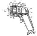
- FIG. 1shows an exemplary scanning system 100 adapted for handheld operation.
- An exemplary handheld scanning appliance or handpiece 102is provided. It includes a grip section 104 and a body section 106 .
- An image formation system 151shown in phantom, can be controlled and can direct image data to an onboard embedded processor 109 .
- This processorcan include a scanning software application 113 by which lighting is controlled, images are acquired and image data is interpreted into usable information (for example, alphanumeric strings derived from the symbols (such as the depicted two-dimensional barcode image 195 ).
- the decoded informationcan be directed via a cable 111 to a PC or other data storage device 112 having (for example) a display 114 , keyboard 116 and mouse 118 , where it can be stored and further manipulated using an appropriate application 121 .
- the cable 111can be directly connected to an interface in the scanning appliance and an appropriate interface in the computer 112 .
- the computer-based application 121performs various image interpretation/decoding and lighting control functions as needed.
- the precise arrangement of the handheld scanning appliance with respect to an embedded processor, computer or other processoris highly variable.
- a wireless interconnectcan be provided in which no cable 111 is present.
- the depicted microcomputercan be substituted with another processing device, including an onboard processor or a miniaturized processing unit such as a personal digital assistant or other small-scale computing device.
- the scanning application 113can be adapted to respond to inputs from the scanning appliance 102 .
- an internal camera image sensorthat is part of the image formation system 151 ) acquires an image of a region of interest 131 on an object 105 .
- the exemplary region of interestincludes a two-dimensional symbol 195 that can be used to identify the object 105 .
- Identification and other processing functionsare carried out by the scanning application 113 , based upon image data transmitted from the hand held scanning appliance 102 to the processor 109 .
- a visual indicator 141can be illuminated by signals from the processor 109 to indicate a successful read and decode of the symbol 195 .
- a diffuse illuminatoremploying a perimeter array of light sources that project light inwardly to a regularly spaced grid assembly is commercially available from CCS of Japan.
- the grid assemblyis, in essence a plate of transparent material having a series of reflective spots (a “grid”) applied to one side and opposite a fully transparent side. The light is internally reflected to bounce off of the spots and through the opposing transparent side, and toward a subject. The image resides on the grid side of the illuminator and views the subject through the grid.
- This illuminatorprovides a very consistent light across its surface that is substantially unbroken due to the lack of a large central aperture and that avoids spotting effects due to the even spread of light around the matrix of the grid.
- This light spreadis generated by a substantially continuous array of light sources (red LEDs, for example) that are provided around the perimeter of the grid.
- the unique geometry of the gridprojects the array's light downwardly onto the subject, while blocking upward transmission of light from the array.
- the gridincludes sufficient open space between grid elements (reflectors) so that, at the camera's normal standoff from the grid, it appears largely invisible in the acquired image, much like a window screen viewed at a distance.
- this type of diffuse illuminatoris specifically adapted for fixed-mount applications, in which the subject is provided at a stationary inspection location with a fixed camera located thereabove.
- the illuminatoris also relatively large in footprint (30 or more centimeters square in many versions.
- the illumination arrayis housed in a wide framework that encircles the grid, thus providing a significant degree of non-projecting space along the overall surface area of the grid.
- this type of illuminatoris not adapted for use in a movable handheld environment where the maximum amount of surface area should be devoted to illumination and the overall surface area should be minimized.
- This inventionovercomes the disadvantages of the prior art by providing an illumination system and method for use in a handheld symbology reader that employs a grid assembly having a transparent plate with an imager-facing side and a subject-facing side, in which the imager-facing side includes an applied pattern of reflecting spots or elements adapted, to project a highly diffuse and uniform illumination on a subject.
- the grid assemblydefines a geometry with a large number of transparent spaces between grid elements through which an image of the subject can be acquired, but that is otherwise substantially regular and continuous (tessellated) across the entire inner opening of the reader.
- the area of the grid assemblyis enhanced, and the size of the reader opening is minimized, by locating the light source array so that is projects into the grid assembly at a right angle.
- the light sourcescan, thus, be mounted on a circuit board that is coaxial with the imager's optical axis.
- the light arraycan be provided along with another ring of light sources (potentially on the same circuit board), which are employed to illuminate an external light pipe with a chamfered edge to create low-angle, illumination.
- the light for illuminating the grid assemblycan be provided using an inner light pipe with a distal beveled edge (typically a 45-degree bevel) that bends light from the sources at a 90-degree angle radially into the perimeter edge of the transparent plate of the grid assembly.
- the grid assemblyis provided behind the dark field light pipe's proximal (rearward, toward the interior of the reader) end, and the grid light sources are directed further proximally (rearwardly) into either a 90-degree-bend light pipe or a continuously curving (parabolic, for example) grid.
- the grid assemblyis located forwardly, near the chamfered edge of the dark field light pipe and employs a 90-degree-bend light pipe to direct light from an array of forwardly (toward the distal or outer end of the reader) projecting grid light sources that are coaxial with the dark field light pipe light sources.
- the bending light pipe and dark field light pipecan be optically isolated from each other by an intermediate shield or coating that prevents migration of light between each pipe, either from internally generated light or from reflections from the subject.
- the grid assemblyis located behind the proximal end of the dark field light pipe and provides diffuse light into a conical diffuser can also be illuminated by a plurality of discrete light sources.
- the discrete light sourcesare directed rearwardly and strike a reflector that returns the light toward the conical diffuser.
- the potential problem of varying image intensity about the field of viewcan be addressed by providing a polygonal (square, for example) aperture to the imager lens and arranging the grid elements at a spacing and orientation that is geometrically aligned with the aperture.
- the fraction of area covered by opaque dotsis always constant versus the overall area viewed through the grid, regardless of location in the field of view.
- the aperturecan be substantially coincident with the grid assembly's imager side (containing the grid thereon), and the area external of the aperture can be made opaque to reject stray reflected image light that falls outside of the aperture.
- FIG. 1is a perspective view of a handheld scanning system with integrated illumination according to the prior art
- FIG. 2is a side cross section of a handheld symbology reader that can be employed in connection with the teachings of this invention
- FIG. 3is a somewhat schematic side cross section of a diffuse illumination grid assembly for use in connection with the handheld symbology reader of FIG. 2 ;
- FIG. 4is a plan view on an enlarged segment of an overall diffuse illumination pattern produced on a subject using a grid assembly in accordance with FIG. 3 ;
- FIG. 5is a somewhat schematic side cross section of a reader imager, dark field illumination light pipe and diffuse illuminator employing a grid assembly in accordance with FIG. 2 arranged adjacent to the distal end of the dark field light pipe according to an illustrative embodiment;
- FIG. 6is a somewhat schematic side cross section of a reader imager, dark field illumination light pipe and diffuse illuminator employing a grid assembly in accordance with FIG. 2 arranged rearward of the proximal end of the dark field light pipe according to another illustrative embodiment;
- FIG. 7is a somewhat schematic side cross section of a reader imager, dark field illumination light pipe and diffuse illuminator employing a grid assembly in accordance with FIG. 2 arranged rearward of the proximal end of the dark field light pipe and defining a curved shape according to another illustrative embodiment;
- FIG. 8is a somewhat schematic side cross section of a reader imager, dark field illumination light pipe, diffuse illuminator employing a grid assembly in accordance with FIG. 2 arranged rearward of the proximal end of the dark field light pipe and conical diffuser with discrete illumination sources according to another illustrative embodiment;
- FIG. 9is a cross-sectional perspective view of diffuse illumination assembly employing a light pipe that supports a separate grid assembly formed on a transparent plate according to an alternate embodiment
- FIG. 10is a perspective view of a diffuse illuminator employing a grid assembly, having side-projecting light sources according to an alternate embodiment
- FIG. 11is a partial side cross section of the illumination circuit board, an exemplary side-projecting LED and a portion of the grid illumination plate taken along line 11 - 11 of FIG. 10
- FIG. 12partial side cross section based upon the cross section of FIG. 11 wherein the grid illumination plate includes a convex edge for better light collimation therein according to an alternate embodiment
- FIG. 13is an a perspective view of an exemplary camera, aperture, grid plate and region of interest
- FIG. 14is a partial plan view of an imager side of the illumination grid plate including a circular aperture as shown in FIG. 13 illustrating the cause of intensity variation about the field of view;
- FIG. 15is a partial plan view of an imager side of the illumination grid plate including a square aperture for use in the arrangement of FIG. 13 according to one embodiment.
- FIG. 16is a partial plan view of an object side of the illumination grid plate including a see-through circular aperture for use in the arrangement of FIG. 13 surrounded by an opaque field surrounding the aperture for use in the arrangement of FIG. 13 according to another embodiment.
- FIG. 2shows a cross sectional side view of an illustrative embodiment of the reader 200 according to the present invention.
- the imager 212 and an illumination board 214are positioned on a shock-resistant mounting (not shown) within the housing 206 .
- the processor module and related functional electronic componentsare mounted on a processor board 215 .
- the grip portion 202 and the trigger 204are functionally cooperative with the housing 206 and components of the processor board 215 .
- the grip portion 202includes a conveniently placed trigger 204 that can be actuated by a finger of the user to initiate the image acquisition and decoding function. More particularly, pressing the trigger causes each type and/or color of illumination used in the reader 200 to be projected onto the subject of interest (either in succession or simultaneously), and also causes corresponding acquisition of an image of the subject by the imager.
- the illumination board 214supports a plurality of LEDs 210 that are red in this embodiment (a variety of colors and/or wavelengths (e.g. infrared) can be used).
- the LEDs 210are directed forwardly, toward the distal opening of the reader. These LEDs are positioned behind a passive light pipe 244 that internally transmits light from the ring of LEDs 210 to a front end 230 .
- the front end 230includes a chamfered surface 232 .
- Various examples of a light pipe for use with a reader or similar applicationare shown and described in commonly assigned U.S. patent application Ser. No.
- a shield 250is also provided along the inner surface of the light pipe.
- One function of the shield 250is to prevent transmission of diffuse light (described below) in to the light pipe. Another function is to redirect light transmitted from the reflector (see below) back into the diffuser.
- the ring of LEDs 210acts to produce a red direct bright field effect along with the dark field effect through refraction of some light from the LEDs through the chamfered surface 232 .
- the bright field illumination from the light pipe 230tends not to interfere with the dark field illumination.
- the bright field illuminationis available, however, for larger reading distances (>25 mm between the end 230 and the surface). This is useful for easy-to-read codes, such as black-and-white printed labels.
- a separate bright field illuminatorcan be provided, and as described below. In fact, many available imagers include integral red bright field illuminators. In an alternate embodiment, a separate bright field illuminator can be provided in a discrete color, such as green.
- a tether cord 260provides electrical power to the reader 200 , as well as a communication transmission path for the decoded character string of the encoded information, though it is contemplated that the reader 200 can be configured with battery power and wireless communication for complete portable flexibility.
- the placement of the individual LEDs (or other appropriate light elements) 210is such that the LEDs generally surround the entire perimeter of the light pipe 244 .
- This illustrative LED placementcreates a generally uniform lighting effect.
- the placement and number of these dark-field-illuminating light elements and other light elements described hereinis highly variable.
- the addressing of light elementscan be controlled so that only certain elements are activated at certain times to create the desired overall dark field illumination intensity and/or bias (e.g. lighter on one side than another) to the dark field illumination effect on the subject. This variable-addressing feature is described further below and is discussed in further detail in the above-incorporated U.S. patent applications and in other commonly assigned U.S. patent applications referenced therein.
- a diffuse illumination sourceAs will be described below, a plurality of arrangements for providing diffuse illumination are expressly contemplated. Two general types of arrangements described herein are shown alternatively in FIG. 2 . Both arrangements of illuminators are based upon a diffuse grid assembly as described in the Background of the Invention above. They are centered about the optical axis 270 of the imager 212 and are generally free of enlarged apertures, the imager viewing the subject directly through the grid structure. The first arrangement for a grid illuminator 280 is adjacent to the chamfered or distal end 230 of the dark field light pipe 244 .
- This illuminatoris characterized by a frontal grid member 282 optically connected to a grid light pipe 284 that surrounds the perimeter of the frontal grid member.
- the grid light pipe 284receives light from an array of forwardly directed light sources (LEDs for example) 285 having an appropriate color or wavelength (blue for example).
- the light sourcesare mounted on a circuit board that surrounds the axis 270 and that permits (via a central aperture) an image of the subject to pass into the imager 212 from the reader's distal end.
- the lightis bent radially inward (normal to the axis 270 ) by a chamfered (45-degree) end 286 that internally reflected the light from the axially aligned direction. This end 286 can be coated to avoid transmission of direct bright field light through refraction.
- FIG. 2An alternate arrangement for the diffuse illuminator ( 290 ) is shown in phantom in FIG. 2 .
- This arrangementallows for a somewhat more-compact design in that the grid assembly 292 is located in close proximity to the imager 212 and the light pipe 294 is relatively short. It also places the grid closer to the imager 212 and further from the subject, rendering individual grid elements less visible in the acquired image.
- the array of light sources 296is projected rearwardly, and located on the rear side of the dark field illumination board 214 . Since the illuminator required radially directed light, bending it from either a forward or rearward-projecting direction achieves the same result. As will be described below, there are a number of variations on each general arrangement described herein.
- a pair of aiming LEDs(typically emitting green light) can be provided.
- Aiming LEDsor other light sources) assist in aligning the reader with a subject area by providing a narrow light pattern that can be centered on the subject.
- these aiming LEDsshould be placed ahead of the diffuse illumination grid so that the grid does not obscure their pattern.
- the grid placement shown in phantomis generally more suitable for placement of aiming LEDs as there is more space ahead of the grid. In that case, the illumination board 214 can be used to support the aiming LEDs.
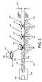
- the geometry of the illumination grid assemblyis now discussed in further detail with reference to FIGS. 3 and 4 .
- the grid assembly 300consists of a plate 304 (constructed from transparent polymer or glass) having two opposing sides, including a “grid” side 302 and a “reflecting” side 306 .
- the grid side 302that carries a matrix of regularly spaced circular grid elements 310 surrounded by transparent spaces 320 .
- the spaces 320 between grid elements 310define open transparent spaces through which viewing of the object by the camera/imager can occur.
- the on-center spacing GCS ( FIG. 4 ) between grid elements 310is approximately 0.40 millimeter in this example.
- the resulting grid element 310combining upper and lower members provides a substantially flat object-facing surface 334 against the grid side 302 of the plate as shown.
- the elements 310appear a uniform optical black to reduce unwanted reflections from the white portions of each element into the imager. Hence only image light passing from the object side, through space 320 between grid elements is viewed by the imager.
- Illuminationis provided around the periphery of the plate 304 using a plurality of light sources (LEDs) 340 arranged in a continuous array.
- LEDslight sources
- these light sources 340are contained in an optically opaque, peripheral framework 350 in the conventional.
- alternative mounting arrangementsare used, as noted in FIG. 2 and as further described below.
- the framework 350 in this examplealso holds the plate 304 in place.
- the reflecting side 306is spaced from the grid side at a spacing that provides a plate thickness TLG of approximately 4.8 millimeters.
- the spacing of the grid side 302 and reflecting sideproduces internal reflection of illumination from the light sources 340 as illustrated by the reflecting rays 370 bouncing between the grid side 302 and the reflecting side 306 .
- These internally reflected rays 370also strike the white centers of each grid element 310 and are refracted into downwardly directed rays 380 that define a high enough angle to overcome internal reflection by the reflecting side.
- the rays 380pass through the reflecting side 306 , and strike the object as highly diffuse illumination.
- the surrounding 0.04-millimeter annulus of blackprevents rays near the edge of each grid element 310 from creating light bounce that would travel back through the space 320 between grid elements, and thereby blind the camera.
- the radially directed light of the light source arrayis translated almost exclusively into direct diffuse illumination ( 380 ) covering the subject widely and evenly.
- FIGS. 5-8some illustrative arrangements of a grid illuminator installed in a handheld symbology reader are now described with reference to FIGS. 5-8 .
- a framework ( 350 in FIG. 3 ) holding a set of radially projecting light sourceswould typically occupy significant portion of the reader's interior surface area (the area radially within the dark field light pipe, for example), thereby reducing the area available to project diffuse illumination.
- each of the embodiments describedincludes a technique for redirecting the illumination radially from a set of axially oriented and axially projecting light sources.
- a set of radially projecting light sourcescan be employed using appropriate mounting arrangements within the reader.
- any embodiment of a handheld reader contemplated hereincan be implemented with only diffuse illumination employing an illumination grid assembly in accordance with this invention.
- Such readersretain many of the advantages of those with a combined direct diffuse and dark field illumination assembly—particularly the ability to provide an even diffuse light pattern across the entire surface of the subject.
- a diffuse-only readermay be preferred where the subject of interest is best viewed using direct diffuse light and size and weight limitations make the omission of the dark field light pipe advantageous.
- FIG. 5shows one illustrative embodiment of the reader's illumination assembly 510 combining a dark field light pipe 512 , having a chamfered distal end 514 with a diffuse illumination grid assembly 520 that is nested within the dark field light pipe.
- the dark field light pipe 512receives light from an array of axially directed light sources (LEDs for example) 516 mounted on an illumination circuit board 518 .
- This boardencircles the central opening 519 defined by the dark field light pipe 512 , allowing for a large central aperture in which the imager 212 may acquire images from the subject.
- the chamfered edge 514defines an angle of approximately 35 degrees with respect to the axial direction (axis 270 ). This angle causes rays 522 projected from the dark field light sources 516 to be internally reflected into the low angle dark field rays 524 that project inwardly toward the central optical axis 270 .
- the illumination board 518also supports a second array of light sources 530 that is radially inward of the first array of sources 516 , and also forwardly projecting into a diffuse illuminator light pipe 532 .
- the diffuse illuminator light pipe 532is a cup having a predetermined frontal cross section shape (round, oval, rectangular or a combination of shapes) that conforms generally to the inside dimension of the dark field light pipe. It can be molded from polymer, such as transparent acrylic or polycarbonate. In this embodiment, it includes a 45-degree front edge 534 that can be coated (dashed line 536 ) or shielded to eliminate refraction through the edge.
- the light pipeincludes a unitary front plate 540 that extends inwardly from the edge 534 to cover the front of the opening 519 .
- the front plate 540is transparent and transmitted from the edge 534 is internally reflected between the front face 542 of the front plate 540 and the rear face 546 . It can be constructed as a unitary member by injection molding or other appropriate techniques. As described above some light striking the rear face 546 encounters the grid 544 of discrete reflective spots each having a structure described above (reflective/white centers with non-reflective/black edges).
- the grid 544is deposited on the rear face 546 of the front plate 540 in a manner described above—for example by printing or deposition techniques. In this location, light passes through the rear face into each grid element where it is refracted at an angle that allows it to pass forwardly through the front face 542 as highly diffuse light.
- a shield(dashed line 550 ) is provided between the inner wall of the dark field light pipe 512 and the outer wall of the diffuse illuminator light pipe 532 . The shield extends up to the two arrays of light sources 516 and 530 to maintain optical separation between each array. This shield 550 generally prevents transmission of reflected or transmitted light from one pipe to the other.
- the overall radial width of the grid assembly 620is increased as because the array of light sources 530 of the grid assembly are located to project axially rearward (rays 638 ), directly behind the forwardly projecting array of light sources 532 , which are aligned with the proximal end 534 of the dark field light pipe 612 .
- the raysare directed radially using a chamfered, reflecting edge 640 as described above.
- the two arrays of light sources 530 , 532are provided to opposite sides of the same illumination circuit board 540 , thereby allowing for a narrow circuit board ring around the inner opening 542 of the reader. This maximizes the degree of diffuse illumination projected from the grid assembly 620 .
- the illumination assembly embodiment 710 of FIG. 7improves upon the limitations in viewing angle ( 670 ) in the embodiment of FIG. 6 by providing a curved illumination grid assembly 720 .
- the assemblyconsists of a trans-parent curved front plate 722 that can define a parabolic, spherical or another curving shape that is generally symmetrical about the imager's optical axis 270 .
- the curved grid assembly 710defines a larger reflected viewing angle 760 that the angle 670 attained with the flat grid assembly 620 of the illumination assembly embodiment 610 shown in FIG. 6 .
- the grid assembly light sources 726are arranged to project rearwardly and are aligned with forwardly projecting dark field light sources 780 , mounted on opposite sides of a narrow (in the radial direction) illumination circuit board 782 .
- a relatively short dark field light pipe 790 with a distal chamfered edge 792is provided. This light pipe 790 generates desired dark field illumination (rays 794 ).
- the conical diffuseris a translucent, diffusive surface that tapers outwardly from the region of the imager toward the distal end. By appropriately directing light sources the entire diffuser surface can be lighted to some degree, allowing it to project a continuous spread of diffuse light that increases the useful viewing angle.
- the conical diffuserdefines an open region without forwardly directed illumination in the region of the imager lens and aiming LEDs ( 220 in FIG. 2 ). This open region about the axis 270 of the reader can generate a darkened center spot on the subject.
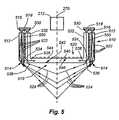
- an illumination assembly 810 with a conical diffuser 812is shown.
- the term “conical diffuser,”is taken to include tapered shapes that may include corners and/or flattened sides as well as round cones.
- the conical diffuser 812is nested within the interior space of the dark field light pipe 814 .
- the dark field light pipe 814includes the above-described chamfered distal end 815 generating dark field light (rays 816 ).
- the diffuseris illuminated by a set of rearwardly projecting light sources 817 that direct light into a rear reflector 818 having a variety of parabolic, stepped or other shapes that are adapted to direct the light along the full length of the inner side of the diffuser 812 .
- the reflectorincludes a matte white reflecting surface with texturing in an illustrative embodiment for creating a further diffusive effect.
- the diffuser 812is optically isolated from the dark field light pipe 814 by a shield 819 having an opaque, non-transmissive surface coating.
- the illumination assemblyalso includes a diffuse illumination grid assembly 820 positioned between the reflector 818 and the imager 212 .
- This grid assembly 820consists of a light pipe 822 having an axially directed forward section 824 that carries internally reflected light from rearwardly projecting light sources 825 into a 45-degree chambered edge 826 and then into a radially directed front plate 828 .
- the front plate 828is transparent, allowing images of a subject to be viewed by the imager 212 therethrough.
- a series of grid elements 830having a construction as described generally herein, is applied to the rear face 832 (imager side) of the front plate 828 . Light internally reflected along the front plate 828 is bounced off the grid elements 830 on the rear face 832 , and then forwardly through the front face 834 of the front plate 828 as highly diffuse illumination.
- a single illumination circuit board 860supports both the diffuser light sources 817 and grid light sources 825 .
- the dark field light sources 862are provided opposite the grid light sources 825 on the same board 860 .
- the shield 819extends sufficiently rearwardly to block migration of light from the dark field light sources 862 into the conical diffuser 812 . This prevents transmission of reflected light and also ensures that, where different color/wavelength light is used for different illumination types and/or where different types of light are toggled at different times, the light from one illuminator does not pass through another illuminator.
- the diffuser light sources 817are located radially inboard from the light pipe sources 825 and 862 . In practice, the diffuser light sources 817 may be fewer in number (four, for example) than the encircling arrays of light sources employed for each light pipe.
- the conical diffuser 812can include an overlying filter, tint or coating to block reflected light from, for example, the dark field illuminator so that it is not retransmitted as diffuse light through the conical diffuser.
- the filtercan be tuned to block the color used in dark field illumination while allowing diffuse illumination color to pass.
- the illustrative grid elements arranged on the plate in a generally rectangular or square packing arrangementsee FIG. 4 . It is expressly contemplated that the organization of grid elements can be based upon another tessellated shape, such as a hexagon or triangle, or upon a geometrically varying or random packing order. Likewise, the size of grid elements and their relative spacing is highly variable. A smaller grid element would tend to be less visible in then image and may be appropriate for certain viewing distances. Similarly, the outline shape of each grid element is highly variable. While circular grid elements are described, the outline shape can be a regular or irregular polygonal (hexagonal, for example) or another curved shape (elliptical, for example).
- FIG. 9details such a grid assembly structure.
- This grid illumination assembly 900shown in cross sectional perspective view, defines the modified rectangular perimeter outline described in the above-incorporated U.S. patent application entitled INTEGRATED ILLUMINATION ASSEMBLY FOR SYMBOLOGY READER, and employed herein according to an illustrative embodiment of the reader 200 .
- the assembly 900consists of a surrounding light pipe 910 with a light-input edge 920 oriented axially and a chamfered 45-degree edge 930 that internally reflects the light radially inward.
- the inner edge 940 of the light pipeincludes a notch area 942 that supports a separate transparent front plate 948 , around its perimeter.
- the front plate 948consists of a (imager-side) grid face 950 having the grid elements applied thereto and an opposing (subject-side) reflecting face 960 that generates desired internal reflection and bounce of light off the elements toward the subject.
- the notchis particularly arranged to allow light to pass from the inner face of the notch 942 into the confronting side edge 944 of the front plate 948 .
- the inside edge 940 of the light pipe 910in regions remote from the notch 942 can be coated or shielded so that light is contained within the pipe and does not migrate into or out of it at these locations.
- an axially oriented light pipeis used to receive light from an array of light sources and redirect the light radially into a separate or unitary front grid illumination plate.
- a light pipeenables a smaller profile and a more-conventional mounting of axially-directed LEDs on a circuit board.
- FIG. 10details an alternate embodiment of a grid illumination assembly 1010 , which employs a conventionally oriented (extending on a plane normal to the optical axis 1020 ) circuit board 1030 to support a set of conventional side-projecting LEDs 1040 that direct light radially inward toward the perimeter edge 1050 of an illumination grid plate 1060 having a layout of grid elements 1070 (shown partially) as described generally herein.
- the circuit board 1030can support dark field LEDs 1080 (shown in phantom) on, for example, the opposing side of the board or on the same side of the board within an outer or inner perimeter ring (not shown).
- the actual perimeter shape of the ringis highly variable. It is shown as a circular shape herein for simplicity. However, the modified rectangle shape as described above ( FIG. 9 ) can be employed, among other shapes.
- the illumination grid plate edge 1050can be a straight cylinder, coaxial with the axis 1020 as shown in FIG. 11 .
- the transmitted rays 1170project from the relatively narrow point region of each LED 1040 through the edge and into the plate 1060 as shown.
- a lens structure(not shown) can be provided between the array of LEDs 1040 and the edge 1050 to improve collimation of the rays in alternate embodiments.
- the perimeter edge 1250 of a modified grid plate 1260can be formed with a convex or other lensmatic shape that improves collimation of the rays 1270 for better internal reflection.
- FIG. 13details a generalized arrangement 1300 for an imager lens 1310 with an associated aperture 1312 .
- the lensis located at a specified standoff distance DO from a given point 1320 on an object surface 1322 , located within a specified field of view (perimeter edge 1324 ).
- the light 1330 from the point 1320is reflected back to the aperture 1312 , passing through the illumination grid plate 1340 .
- the grid surface 1342(imager side) is located at a specified distance DG from the aperture 1312 .
- the relative distances DO and DG, along with the size/shape of the aperture 1312 and location of the point 1320 on the field of viewdictate the size of an area 1350 through which the light 1330 passes. All other factors remaining equal, the size of the area 1350 on the grid plate 1340 will vary for different points within the field of view 1324 . This is because the distance between a point 1320 relative to the aperture will vary as a function of the angle of light with respect to the optical axis 1380 .
- the number of grid elements encompassed by the area 1350will vary. This is illustrated in FIG. 14 , in which the circular aperture generates an area 1350 that partially crosses a number of grid elements (shown on the imager side of a grid 1410 ) to varying degrees. If the circle is slightly larger or slightly smaller a fraction of the area covered by black dots (grid elements) will vary non-linearly relative to the circle area. This non-linearity can lead to intensity fluctuations across the image that may affect the reader's decoding algorithms.
- one solutionis to provide the lens 1310 with a square aperture to generate the square area 1550 on the grid 1410 shown in FIG. 15 .
- the grid arrayis oriented in a square arrangement that is aligned with the square aperture shape.
- the spacing 1560 between grid elementsis also set so that the square area 1550 is equal to a multiple of the grid spacing size so that the fraction of the overall area 1550 covered by dots at any point in the field of view is constant. In this manner, the relative intensity of reflected light received from any point on the field of view is unaltered by the grid. It is contemplated that other polygons and associated grid element layouts may be used to achieve similar intensity-regulating results.
- an alternate solution to the problem of intensity variationis to position the lens so that the aperture (circular in this example) is coincident with the imager side of the grid (the side containing the grid elements applied thereto).
- the grid plate 1610 object sideis provided with a central opening having typical grid elements 1620 and transparent space therebetween. This region corresponds with the imager aperture (with grid elements that are, in actuality, many times more numerous and smaller that those shown).
- the area outside of the aperture regionis coated with opaque paint (black) in this embodiment so that only object-reflected light in the region of the aperture is transmitted through the grid plate, while the surrounding grid elements 1622 reflect diffuse illumination toward the object in a normal manner.
Landscapes
- Physics & Mathematics (AREA)
- Electromagnetism (AREA)
- Engineering & Computer Science (AREA)
- Health & Medical Sciences (AREA)
- General Health & Medical Sciences (AREA)
- Toxicology (AREA)
- Artificial Intelligence (AREA)
- Computer Vision & Pattern Recognition (AREA)
- General Physics & Mathematics (AREA)
- Theoretical Computer Science (AREA)
- Image Input (AREA)
Abstract
Description
Claims (29)
Priority Applications (1)
| Application Number | Priority Date | Filing Date | Title |
|---|---|---|---|
| US11/321,702US7614563B1 (en) | 2005-12-29 | 2005-12-29 | System and method for providing diffuse illumination in a symbology reader |
Applications Claiming Priority (1)
| Application Number | Priority Date | Filing Date | Title |
|---|---|---|---|
| US11/321,702US7614563B1 (en) | 2005-12-29 | 2005-12-29 | System and method for providing diffuse illumination in a symbology reader |
Publications (1)
| Publication Number | Publication Date |
|---|---|
| US7614563B1true US7614563B1 (en) | 2009-11-10 |
Family
ID=41261466
Family Applications (1)
| Application Number | Title | Priority Date | Filing Date |
|---|---|---|---|
| US11/321,702Active2027-04-24US7614563B1 (en) | 2005-12-29 | 2005-12-29 | System and method for providing diffuse illumination in a symbology reader |
Country Status (1)
| Country | Link |
|---|---|
| US (1) | US7614563B1 (en) |
Cited By (49)
| Publication number | Priority date | Publication date | Assignee | Title |
|---|---|---|---|---|
| US20080105748A1 (en)* | 2006-09-19 | 2008-05-08 | Ming Lei | Methods for illuminating barcodes |
| US20080105746A1 (en)* | 2006-09-19 | 2008-05-08 | Ming Lei | Devices and/or systems for automatically imaging barcodes |
| US20110000966A1 (en)* | 2009-07-06 | 2011-01-06 | Liu Shu-Shien | Barcode reading device |
| US20110017822A1 (en)* | 2009-07-27 | 2011-01-27 | Mike Dvorak | Ballot Processing System |
| US20120067957A1 (en)* | 2010-09-17 | 2012-03-22 | Keyence Corporation | Illumination Setting Support Apparatus Of Optical Information Reading Apparatus |
| US20120120490A1 (en)* | 2006-12-29 | 2012-05-17 | Cognex Corporation | Manually Adjustable Ruggedized Focus Mechanism |
| WO2013184970A2 (en) | 2012-06-08 | 2013-12-12 | Datalogic ADC, Inc. | Imaging reader with improved illumination |
| US8847150B2 (en) | 2012-10-08 | 2014-09-30 | Symbol Technologies, Inc. | Object detecting system for imaging-based barcode readers |
| US8857720B1 (en) | 2013-10-24 | 2014-10-14 | The Code Corporation | Diffuse bright field illumination system for a barcode reader |
| US9569653B1 (en) | 2016-06-13 | 2017-02-14 | Datalogic IP Tech, S.r.l. | Dark field illumination system obtained in a tilted plane |
| US20170353656A1 (en)* | 2016-06-01 | 2017-12-07 | Netgear, Inc. | Camera With Polygonal Lens |
| US9934415B1 (en)* | 2017-04-20 | 2018-04-03 | Xerox Corporation | Handheld reader having transparent circuit board for alignment of multiple electrical contacts |
| US10007858B2 (en) | 2012-05-15 | 2018-06-26 | Honeywell International Inc. | Terminals and methods for dimensioning objects |
| US20180177371A1 (en)* | 2013-04-11 | 2018-06-28 | Samsung Electronics Co., Ltd. | Sensor module and robot cleaner having the same |
| EP3343429A1 (en)* | 2016-12-28 | 2018-07-04 | Hand Held Products, Inc. | Illuminator for dpm scanner |
| US10025314B2 (en) | 2016-01-27 | 2018-07-17 | Hand Held Products, Inc. | Vehicle positioning and object avoidance |
| US10060729B2 (en) | 2014-10-21 | 2018-08-28 | Hand Held Products, Inc. | Handheld dimensioner with data-quality indication |
| US10066982B2 (en) | 2015-06-16 | 2018-09-04 | Hand Held Products, Inc. | Calibrating a volume dimensioner |
| US10094650B2 (en) | 2015-07-16 | 2018-10-09 | Hand Held Products, Inc. | Dimensioning and imaging items |
| US10121039B2 (en) | 2014-10-10 | 2018-11-06 | Hand Held Products, Inc. | Depth sensor based auto-focus system for an indicia scanner |
| US10134120B2 (en) | 2014-10-10 | 2018-11-20 | Hand Held Products, Inc. | Image-stitching for dimensioning |
| US10140724B2 (en) | 2009-01-12 | 2018-11-27 | Intermec Ip Corporation | Semi-automatic dimensioning with imager on a portable device |
| US10163216B2 (en) | 2016-06-15 | 2018-12-25 | Hand Held Products, Inc. | Automatic mode switching in a volume dimensioner |
| US10203402B2 (en) | 2013-06-07 | 2019-02-12 | Hand Held Products, Inc. | Method of error correction for 3D imaging device |
| US10218964B2 (en) | 2014-10-21 | 2019-02-26 | Hand Held Products, Inc. | Dimensioning system with feedback |
| US10225544B2 (en) | 2015-11-19 | 2019-03-05 | Hand Held Products, Inc. | High resolution dot pattern |
| US10240914B2 (en) | 2014-08-06 | 2019-03-26 | Hand Held Products, Inc. | Dimensioning system with guided alignment |
| US10249030B2 (en) | 2015-10-30 | 2019-04-02 | Hand Held Products, Inc. | Image transformation for indicia reading |
| US10247547B2 (en) | 2015-06-23 | 2019-04-02 | Hand Held Products, Inc. | Optical pattern projector |
| EP3480725A1 (en)* | 2017-10-31 | 2019-05-08 | Hand Held Products, Inc. | Direct part marking scanners including dome diffusers with edge illumination assemblies |
| US10318778B2 (en) | 2012-11-15 | 2019-06-11 | Symbol Technologies, Llc | Reducing perceived brightness of illumination light source in electro-optical readers that illuminate and read targets by image capture |
| US10321127B2 (en) | 2012-08-20 | 2019-06-11 | Intermec Ip Corp. | Volume dimensioning system calibration systems and methods |
| US10339352B2 (en) | 2016-06-03 | 2019-07-02 | Hand Held Products, Inc. | Wearable metrological apparatus |
| EP3528042A1 (en)* | 2018-02-16 | 2019-08-21 | Sick AG | Camera and method for detecting image data |
| US10393508B2 (en) | 2014-10-21 | 2019-08-27 | Hand Held Products, Inc. | Handheld dimensioning system with measurement-conformance feedback |
| US10467806B2 (en) | 2012-05-04 | 2019-11-05 | Intermec Ip Corp. | Volume dimensioning systems and methods |
| US10584962B2 (en) | 2018-05-01 | 2020-03-10 | Hand Held Products, Inc | System and method for validating physical-item security |
| US10593130B2 (en) | 2015-05-19 | 2020-03-17 | Hand Held Products, Inc. | Evaluating image values |
| US10612958B2 (en) | 2015-07-07 | 2020-04-07 | Hand Held Products, Inc. | Mobile dimensioner apparatus to mitigate unfair charging practices in commerce |
| US10733748B2 (en) | 2017-07-24 | 2020-08-04 | Hand Held Products, Inc. | Dual-pattern optical 3D dimensioning |
| US10775165B2 (en) | 2014-10-10 | 2020-09-15 | Hand Held Products, Inc. | Methods for improving the accuracy of dimensioning-system measurements |
| US10908013B2 (en) | 2012-10-16 | 2021-02-02 | Hand Held Products, Inc. | Dimensioning system |
| US10909708B2 (en) | 2016-12-09 | 2021-02-02 | Hand Held Products, Inc. | Calibrating a dimensioner using ratios of measurable parameters of optic ally-perceptible geometric elements |
| US10922506B2 (en)* | 2017-06-06 | 2021-02-16 | Sicpa Holding Sa | Illumination device for an optical system of a reader apparatus |
| US11029762B2 (en) | 2015-07-16 | 2021-06-08 | Hand Held Products, Inc. | Adjusting dimensioning results using augmented reality |
| US11047672B2 (en) | 2017-03-28 | 2021-06-29 | Hand Held Products, Inc. | System for optically dimensioning |
| DE102021004183B3 (en) | 2020-02-05 | 2022-07-21 | M-Vision Co., Ltd. | lighting device |
| US11639846B2 (en) | 2019-09-27 | 2023-05-02 | Honeywell International Inc. | Dual-pattern optical 3D dimensioning |
| US11847799B2 (en)* | 2022-02-28 | 2023-12-19 | Logitech Europe S.A. | Color matching system for product manufacturing |
Citations (115)
| Publication number | Priority date | Publication date | Assignee | Title |
|---|---|---|---|---|
| US2357378A (en) | 1941-12-01 | 1944-09-05 | Bausch & Lomb | Microscope illuminator |
| US3857626A (en) | 1971-12-10 | 1974-12-31 | Bausch & Lomb | Microscope coaxial illumination apparatus |
| US3961198A (en) | 1975-04-28 | 1976-06-01 | Rockwell International Corporation | Visually alignable sensor wand which excludes unwanted light from a sensor system |
| US4282425A (en) | 1979-07-25 | 1981-08-04 | Norand Corporation | Instant portable bar code reader |
| US4570057A (en) | 1981-12-28 | 1986-02-11 | Norand Corporation | Instant portable bar code reader |
| US4766300A (en) | 1984-08-06 | 1988-08-23 | Norand Corporation | Instant portable bar code reader |
| EP0185782B1 (en) | 1984-12-28 | 1989-03-15 | International Business Machines Corporation | Waveguide for an optical near-field microscope |
| US4820911A (en) | 1986-07-11 | 1989-04-11 | Photographic Sciences Corporation | Apparatus for scanning and reading bar codes |
| US5019699A (en) | 1988-08-31 | 1991-05-28 | Norand Corporation | Hand-held optical character reader with means for instantaneously reading information from a predetermined area at an optical sensing area |
| US5149948A (en) | 1990-07-16 | 1992-09-22 | Computer Identics | Improved bar code reader system for reading bar codes under high specular reflection conditions with a variety of surface effects |
| US5177346A (en) | 1989-12-13 | 1993-01-05 | Computer Identics | Bar code reader system for reading bar code labels with a highly specular and low contrast surface |
| US5258606A (en) | 1981-12-28 | 1993-11-02 | Norand Corporation | Instant portable bar code reader |
| US5291009A (en) | 1992-02-27 | 1994-03-01 | Roustaei Alexander R | Optical scanning head |
| US5313373A (en) | 1992-11-25 | 1994-05-17 | United Parcel Service Of America, Inc. | Apparatus for the uniform illumination of a surface |
| US5319182A (en) | 1992-03-04 | 1994-06-07 | Welch Allyn, Inc. | Integrated solid state light emitting and detecting array and apparatus employing said array |
| US5331176A (en) | 1992-04-10 | 1994-07-19 | Veritec Inc. | Hand held two dimensional symbol reader with a symbol illumination window |
| US5349172A (en) | 1992-02-27 | 1994-09-20 | Alex Roustaei | Optical scanning head |
| US5354977A (en) | 1992-02-27 | 1994-10-11 | Alex Roustaei | Optical scanning head |
| US5378883A (en) | 1991-07-19 | 1995-01-03 | Omniplanar Inc. | Omnidirectional wide range hand held bar code reader |
| US5406060A (en) | 1993-05-06 | 1995-04-11 | Opticon Inc. | Bar code reader for sensing at an acute angle |
| US5408084A (en) | 1993-02-18 | 1995-04-18 | United Parcel Service Of America, Inc. | Method and apparatus for illumination and imaging of a surface using 2-D LED array |
| US5422472A (en)* | 1992-12-04 | 1995-06-06 | Psc, Inc. | Optical symbol (bar code) reading systems having an electro-optic receptor with embedded grating rings |
| US5430285A (en) | 1993-08-20 | 1995-07-04 | Welch Allyn, Inc. | Illumination system for optical reader |
| US5461417A (en) | 1993-02-16 | 1995-10-24 | Northeast Robotics, Inc. | Continuous diffuse illumination method and apparatus |
| US5463214A (en) | 1994-03-04 | 1995-10-31 | Welch Allyn, Inc. | Apparatus for optimizing throughput in decoded-output scanners and method of using same |
| US5469294A (en) | 1992-05-01 | 1995-11-21 | Xrl, Inc. | Illumination system for OCR of indicia on a substrate |
| US5481098A (en) | 1993-11-09 | 1996-01-02 | Spectra-Physics Scanning Systems, Inc. | Method and apparatus for reading multiple bar code formats |
| US5484994A (en) | 1993-10-18 | 1996-01-16 | Roustaei; Alexander | Optical scanning head with improved resolution |
| US5500516A (en) | 1994-08-30 | 1996-03-19 | Norand Corporation | Portable oblique optical reader system and method |
| US5504367A (en) | 1994-03-21 | 1996-04-02 | Intermec Corporation | Symbology reader illumination system |
| US5515452A (en) | 1992-12-31 | 1996-05-07 | Electroglas, Inc. | Optical character recognition illumination method and system |
| US5514858A (en) | 1995-02-10 | 1996-05-07 | Intermec Corporation | Method and apparatus for decoding unresolved complex multi-width bar code symbology profiles |
| US5569902A (en) | 1995-01-17 | 1996-10-29 | Welch Allyn, Inc. | Contact two-dimensional bar code reader having pressure actuated switch |
| US5585616A (en) | 1995-05-05 | 1996-12-17 | Rockwell International Corporation | Camera for capturing and decoding machine-readable matrix symbol images applied to reflective surfaces |
| US5586212A (en) | 1994-07-06 | 1996-12-17 | Hewlett-Packard | Optical wave guide for hand-held scanner |
| US5591955A (en) | 1993-05-11 | 1997-01-07 | Laser; Vadim | Portable data file readers |
| US5598007A (en) | 1994-03-21 | 1997-01-28 | Intermec Corporation | Symbology reader with fixed focus spotter beam |
| US5606160A (en) | 1993-03-25 | 1997-02-25 | Asahi Kogaku Kogyo Kabushiki Kaisha | Symbol reading device |
| US5619029A (en) | 1995-04-04 | 1997-04-08 | Rockwell International Corporation | Imaging enhancement for touch cameras |
| US5623137A (en) | 1993-08-20 | 1997-04-22 | Welch Allyn, Inc. | Illumination apparatus for optical readers |
| US5659167A (en) | 1994-04-05 | 1997-08-19 | Metanetics Corporation | Visually interactive decoding of dataforms |
| US5697699A (en) | 1993-09-09 | 1997-12-16 | Asahi Kogaku Kogyo Kabushiki Kaisha | Lighting apparatus |
| US5703348A (en) | 1994-12-26 | 1997-12-30 | Kabushiki Kaisha Tec | Hand-held optical code reader |
| US5723868A (en) | 1995-05-15 | 1998-03-03 | Welch Allyn, Inc. | Illuminating assembly for use with bar code readers |
| US5734153A (en) | 1985-02-28 | 1998-03-31 | Symbol Technologies, Inc. | Hand-held scanning head with aiming beam |
| US5750974A (en) | 1995-04-13 | 1998-05-12 | Keyence Corporation | Lighting apparatus having light emitting diodes arranged in a plurality of planes on a printed circuit board |
| US5756981A (en) | 1992-02-27 | 1998-05-26 | Symbol Technologies, Inc. | Optical scanner for reading and decoding one- and-two-dimensional symbologies at variable depths of field including memory efficient high speed image processing means and high accuracy image analysis means |
| US5773810A (en) | 1996-03-29 | 1998-06-30 | Welch Allyn, Inc. | Method for generating real time degree of focus signal for handheld imaging device |
| US5777314A (en) | 1992-02-27 | 1998-07-07 | Symbol | Optical scanner with fixed focus optics |
| US5783811A (en) | 1995-06-26 | 1998-07-21 | Metanetics Corporation | Portable data collection device with LED targeting and illumination assembly |
| US5786586A (en) | 1995-01-17 | 1998-07-28 | Welch Allyn, Inc. | Hand-held optical reader having a detachable lens-guide assembly |
| US5793033A (en) | 1996-03-29 | 1998-08-11 | Metanetics Corporation | Portable data collection device with viewing assembly |
| US5811784A (en) | 1995-06-26 | 1998-09-22 | Telxon Corporation | Extended working range dataform reader |
| US5859418A (en) | 1996-01-25 | 1999-01-12 | Symbol Technologies, Inc. | CCD-based bar code scanner with optical funnel |
| US5861910A (en) | 1996-04-02 | 1999-01-19 | Mcgarry; E. John | Image formation apparatus for viewing indicia on a planar specular substrate |
| US5894348A (en) | 1994-06-17 | 1999-04-13 | Kensington Laboratories, Inc. | Scribe mark reader |
| US5907148A (en) | 1994-08-22 | 1999-05-25 | Casio Computer Co., Ltd. | Portable reading apparatus for scan-reading a code using a laser light beam |
| US5920643A (en) | 1997-05-16 | 1999-07-06 | Northeast Robotics Llc | Flexible lighting element circuit and method of manufacturing the same |
| WO1999049347A1 (en) | 1998-03-20 | 1999-09-30 | Auto Image Id, Inc. | Target illumination device |
| US5969321A (en) | 1986-08-08 | 1999-10-19 | Norand Corporation | Hand-held optically readable information set reader with operation over a range of distances |
| US5984494A (en) | 1995-09-08 | 1999-11-16 | Jimmy G. Cook | Light shield for an illumination system |
| US6022124A (en) | 1997-08-19 | 2000-02-08 | Ppt Vision, Inc. | Machine-vision ring-reflector illumination system and method |
| US6034379A (en) | 1996-03-01 | 2000-03-07 | Intermec Ip Corp. | Code reader having replaceable optics assemblies supporting multiple illuminators |
| US6036095A (en) | 1996-05-17 | 2000-03-14 | Asahi Kogaku Kogyo Kabushiki Kaisha | Data symbol reader with observation window |
| US6039254A (en) | 1993-03-18 | 2000-03-21 | Siemens Aktiengesellschaft | Method for imaging bar codes |
| US6042012A (en) | 1994-12-23 | 2000-03-28 | Spectra-Physics Scanning Systems, Inc. | Method and apparatus for reading images without need for self-generated illumination source |
| US6045047A (en) | 1995-01-17 | 2000-04-04 | Welch Allyn Data Collection, Inc. | Two-dimensional part reader having a focussing guide |
| US6060722A (en) | 1995-05-15 | 2000-05-09 | Havens; William H. | Optical reader having illumination assembly including improved aiming pattern generator |
| US6105869A (en) | 1997-10-31 | 2000-08-22 | Microscan Systems, Incorporated | Symbol reading device including optics for uniformly illuminating symbology |
| US6119939A (en) | 1998-07-08 | 2000-09-19 | Welch Allyn, Inc. | Optical assembly for barcode scanner |
| US6141046A (en) | 1994-10-25 | 2000-10-31 | Roth; Stephen Anthony | Electronic camera having an illuminator with dispersing ring lens |
| US6158661A (en) | 1981-12-28 | 2000-12-12 | Intermec Ip Corp. | Instant portable bar code reader |
| US6164544A (en) | 1998-07-08 | 2000-12-26 | Welch Allyn Data Collection, Inc. | Adjustable illumination system for a barcode scanner |
| US6210013B1 (en) | 1996-03-10 | 2001-04-03 | Imperial Chemical Industries Plc | Refrigerator comprising edge-lit panel illumination system |
| US6223986B1 (en) | 1997-04-17 | 2001-05-01 | Psc Scanning, Inc. | Aiming aid for optical data reading |
| US6234397B1 (en) | 1998-10-22 | 2001-05-22 | Symbol Technologies, Inc. | Techniques for reading two dimensional code, including maxicode |
| US6247645B1 (en) | 1999-01-25 | 2001-06-19 | International Business Machines Corporation | Optical reader with combined housing and light pipe |
| US6250551B1 (en) | 1998-06-12 | 2001-06-26 | Symbol Technologies, Inc. | Autodiscrimination and line drawing techniques for code readers |
| US6260763B1 (en) | 1996-02-06 | 2001-07-17 | Psc Scanning, Inc. | Integral illumination source/collection lens assembly for data reading system |
| US6267294B1 (en) | 1998-09-11 | 2001-07-31 | Robotic Vision Systems Inc. | Method of operating a charge coupled device in an accelerated mode, and in conjunction with an optical symbology imager |
| WO2001063258A1 (en) | 2000-02-25 | 2001-08-30 | Robotic Vision Systems, Inc. | Optimal symbology illumination-apparatus and method |
| US6283374B1 (en) | 1998-09-11 | 2001-09-04 | Robotic Vision Systems, Inc. | Symbology imaging and reading apparatus and method |
| US20020000472A1 (en) | 1999-08-04 | 2002-01-03 | John R. Hattersley | Optical symbol scanner with low angle illumination |
| US6340114B1 (en) | 1998-06-12 | 2002-01-22 | Symbol Technologies, Inc. | Imaging engine and method for code readers |
| US6347163B2 (en) | 1994-10-26 | 2002-02-12 | Symbol Technologies, Inc. | System for reading two-dimensional images using ambient and/or projected light |
| US6360948B1 (en) | 1998-11-27 | 2002-03-26 | Denso Corporation | Method of reading two-dimensional code and storage medium thereof |
| US6385507B1 (en) | 1999-06-24 | 2002-05-07 | U.S. Philips Corporation | Illumination module |
| US6385352B1 (en) | 1994-10-26 | 2002-05-07 | Symbol Technologies, Inc. | System and method for reading and comparing two-dimensional images |
| US20020096566A1 (en) | 2000-11-01 | 2002-07-25 | Welch Allyn, Inc. | Adjustable illumination system for a barcode scanner |
| US6435411B1 (en) | 1997-04-21 | 2002-08-20 | Intermec Ip Corp. | Optoelectronic device for acquisition of images, in particular of bar codes |
| WO2002075637A1 (en) | 2001-03-19 | 2002-09-26 | Gavitec Ag | Reader with an image recording unit for reading a code and method for reading a code |
| US6491223B1 (en) | 1996-09-03 | 2002-12-10 | Hand Held Products, Inc. | Autodiscriminating optical reader |
| US6513714B1 (en) | 1998-09-14 | 2003-02-04 | Psc Scanning, Inc. | Character reconstruction and element level processing in bar code scanning system |
| US20030058631A1 (en)* | 2001-09-25 | 2003-03-27 | Kenji Yoneda | Lighting apparatus for insepection |
| US6592040B2 (en) | 1998-03-20 | 2003-07-15 | Symbol Technologies, Inc. | Hand-held bar code reader with single printed circuit board |
| US6601768B2 (en) | 2001-03-08 | 2003-08-05 | Welch Allyn Data Collection, Inc. | Imaging module for optical reader comprising refractive diffuser |
| US6607128B1 (en) | 1998-07-08 | 2003-08-19 | Welch Allyn Data Collection Inc. | Optical assembly for barcode scanner |
| US6661521B1 (en) | 1998-09-11 | 2003-12-09 | Robotic Vision Systems, Inc. | Diffuse surface illumination apparatus and methods |
| WO2004000064A1 (en) | 2002-06-25 | 2003-12-31 | Schwan-Stabilo Schwanhäusser Gmbh & Co. Kg | Receptacle for accommodating at least one pencil |
| US6831290B2 (en)* | 2002-07-16 | 2004-12-14 | Strube, Inc. | Electro-optic fluid quantity measurement system |
| US6832725B2 (en) | 1999-10-04 | 2004-12-21 | Hand Held Products, Inc. | Optical reader comprising multiple color illumination |
| US20050087601A1 (en) | 2003-10-24 | 2005-04-28 | Gerst Carl W.Iii | Light pipe illumination system and method |
| WO2005043449A1 (en) | 2003-10-24 | 2005-05-12 | Cognex Technology And Investment Corporation | Method and apparatus for providing omnidirectional lighting in a scanning device |
| US20060027659A1 (en) | 2003-08-01 | 2006-02-09 | Symbol Technologies, Inc. | Integrated exit window and imaging engine |
| US7021542B2 (en) | 2003-08-01 | 2006-04-04 | Symbol Technologies, Inc. | Imaging and illumination engine for an optical code reader |
| US7044377B2 (en) | 2003-08-01 | 2006-05-16 | Symbol Technologies Inc. | Plug-and-play imaging and illumination engine for an optical code reader |
| US20060133757A1 (en) | 2004-12-16 | 2006-06-22 | Laurens Nunnink | Hand held symbology reader illumination diffuser |
| US7090132B2 (en) | 2002-06-11 | 2006-08-15 | Hand Held Products, Inc. | Long range optical reader |
| US7131587B2 (en) | 2004-03-02 | 2006-11-07 | Symbol Technologies, Inc. | System and method for illuminating and reading optical codes imprinted or displayed on reflective surfaces |
| US7187825B2 (en) | 2003-12-17 | 2007-03-06 | Symbol Technologies, Inc. | System and method for extending viewing angle of light emitted from light pipe |
| US7204420B2 (en) | 2004-08-31 | 2007-04-17 | Symbol Technologies, Inc. | Scanner and method for eliminating specular reflection |
| US7204418B2 (en) | 2004-12-08 | 2007-04-17 | Symbol Technologies, Inc. | Pulsed illumination in imaging reader |
| US20070090193A1 (en) | 2005-10-24 | 2007-04-26 | Laurens Nunnink | Integrated illumination assembly for symbology reader |
| US20070152064A1 (en) | 2005-12-30 | 2007-07-05 | Laurens Nunnink | Diffuse light ring for reading encoded symbols |
| US7270274B2 (en) | 1999-10-04 | 2007-09-18 | Hand Held Products, Inc. | Imaging module comprising support post for optical reader |
- 2005
- 2005-12-29USUS11/321,702patent/US7614563B1/enactiveActive
Patent Citations (131)
| Publication number | Priority date | Publication date | Assignee | Title |
|---|---|---|---|---|
| US2357378A (en) | 1941-12-01 | 1944-09-05 | Bausch & Lomb | Microscope illuminator |
| US3857626A (en) | 1971-12-10 | 1974-12-31 | Bausch & Lomb | Microscope coaxial illumination apparatus |
| US3961198A (en) | 1975-04-28 | 1976-06-01 | Rockwell International Corporation | Visually alignable sensor wand which excludes unwanted light from a sensor system |
| US4282425A (en) | 1979-07-25 | 1981-08-04 | Norand Corporation | Instant portable bar code reader |
| US5258606A (en) | 1981-12-28 | 1993-11-02 | Norand Corporation | Instant portable bar code reader |
| US4570057A (en) | 1981-12-28 | 1986-02-11 | Norand Corporation | Instant portable bar code reader |
| US6158661A (en) | 1981-12-28 | 2000-12-12 | Intermec Ip Corp. | Instant portable bar code reader |
| US4766300A (en) | 1984-08-06 | 1988-08-23 | Norand Corporation | Instant portable bar code reader |
| EP0185782B1 (en) | 1984-12-28 | 1989-03-15 | International Business Machines Corporation | Waveguide for an optical near-field microscope |
| US5734153A (en) | 1985-02-28 | 1998-03-31 | Symbol Technologies, Inc. | Hand-held scanning head with aiming beam |
| US4820911A (en) | 1986-07-11 | 1989-04-11 | Photographic Sciences Corporation | Apparatus for scanning and reading bar codes |
| US5969321A (en) | 1986-08-08 | 1999-10-19 | Norand Corporation | Hand-held optically readable information set reader with operation over a range of distances |
| US5019699A (en) | 1988-08-31 | 1991-05-28 | Norand Corporation | Hand-held optical character reader with means for instantaneously reading information from a predetermined area at an optical sensing area |
| US5177346A (en) | 1989-12-13 | 1993-01-05 | Computer Identics | Bar code reader system for reading bar code labels with a highly specular and low contrast surface |
| US5149948A (en) | 1990-07-16 | 1992-09-22 | Computer Identics | Improved bar code reader system for reading bar codes under high specular reflection conditions with a variety of surface effects |
| US5378883A (en) | 1991-07-19 | 1995-01-03 | Omniplanar Inc. | Omnidirectional wide range hand held bar code reader |
| US5349172A (en) | 1992-02-27 | 1994-09-20 | Alex Roustaei | Optical scanning head |
| US5354977A (en) | 1992-02-27 | 1994-10-11 | Alex Roustaei | Optical scanning head |
| US5532467A (en) | 1992-02-27 | 1996-07-02 | Roustaei; Alex | Optical scanning head |
| US5756981A (en) | 1992-02-27 | 1998-05-26 | Symbol Technologies, Inc. | Optical scanner for reading and decoding one- and-two-dimensional symbologies at variable depths of field including memory efficient high speed image processing means and high accuracy image analysis means |
| US5777314A (en) | 1992-02-27 | 1998-07-07 | Symbol | Optical scanner with fixed focus optics |
| US5291009A (en) | 1992-02-27 | 1994-03-01 | Roustaei Alexander R | Optical scanning head |
| US5319182A (en) | 1992-03-04 | 1994-06-07 | Welch Allyn, Inc. | Integrated solid state light emitting and detecting array and apparatus employing said array |
| US5331176A (en) | 1992-04-10 | 1994-07-19 | Veritec Inc. | Hand held two dimensional symbol reader with a symbol illumination window |
| US5469294A (en) | 1992-05-01 | 1995-11-21 | Xrl, Inc. | Illumination system for OCR of indicia on a substrate |
| US5313373A (en) | 1992-11-25 | 1994-05-17 | United Parcel Service Of America, Inc. | Apparatus for the uniform illumination of a surface |
| US5422472A (en)* | 1992-12-04 | 1995-06-06 | Psc, Inc. | Optical symbol (bar code) reading systems having an electro-optic receptor with embedded grating rings |
| US5515452A (en) | 1992-12-31 | 1996-05-07 | Electroglas, Inc. | Optical character recognition illumination method and system |
| US5461417A (en) | 1993-02-16 | 1995-10-24 | Northeast Robotics, Inc. | Continuous diffuse illumination method and apparatus |
| US5408084A (en) | 1993-02-18 | 1995-04-18 | United Parcel Service Of America, Inc. | Method and apparatus for illumination and imaging of a surface using 2-D LED array |
| US6039254A (en) | 1993-03-18 | 2000-03-21 | Siemens Aktiengesellschaft | Method for imaging bar codes |
| US5606160A (en) | 1993-03-25 | 1997-02-25 | Asahi Kogaku Kogyo Kabushiki Kaisha | Symbol reading device |
| US5406060A (en) | 1993-05-06 | 1995-04-11 | Opticon Inc. | Bar code reader for sensing at an acute angle |
| US5992751A (en) | 1993-05-11 | 1999-11-30 | Norand Corporation | Portable data file readers |
| US5591955A (en) | 1993-05-11 | 1997-01-07 | Laser; Vadim | Portable data file readers |
| US5430285A (en) | 1993-08-20 | 1995-07-04 | Welch Allyn, Inc. | Illumination system for optical reader |
| US5623137A (en) | 1993-08-20 | 1997-04-22 | Welch Allyn, Inc. | Illumination apparatus for optical readers |
| US5697699A (en) | 1993-09-09 | 1997-12-16 | Asahi Kogaku Kogyo Kabushiki Kaisha | Lighting apparatus |
| US6033090A (en) | 1993-09-09 | 2000-03-07 | Asahi Kogaku Kogyo Kabushiki Kaisha | Lighting apparatus |
| US5484994A (en) | 1993-10-18 | 1996-01-16 | Roustaei; Alexander | Optical scanning head with improved resolution |
| US5481098A (en) | 1993-11-09 | 1996-01-02 | Spectra-Physics Scanning Systems, Inc. | Method and apparatus for reading multiple bar code formats |
| US5463214A (en) | 1994-03-04 | 1995-10-31 | Welch Allyn, Inc. | Apparatus for optimizing throughput in decoded-output scanners and method of using same |
| US5598007A (en) | 1994-03-21 | 1997-01-28 | Intermec Corporation | Symbology reader with fixed focus spotter beam |
| US5886338A (en) | 1994-03-21 | 1999-03-23 | Intermec Ip Corporation | Symbology reader illumination system |
| US5684290A (en) | 1994-03-21 | 1997-11-04 | Intermec Corporation | Symbology reader illumination system |
| US5504367A (en) | 1994-03-21 | 1996-04-02 | Intermec Corporation | Symbology reader illumination system |
| US5659167A (en) | 1994-04-05 | 1997-08-19 | Metanetics Corporation | Visually interactive decoding of dataforms |
| US5894348A (en) | 1994-06-17 | 1999-04-13 | Kensington Laboratories, Inc. | Scribe mark reader |
| US5586212A (en) | 1994-07-06 | 1996-12-17 | Hewlett-Packard | Optical wave guide for hand-held scanner |
| US5907148A (en) | 1994-08-22 | 1999-05-25 | Casio Computer Co., Ltd. | Portable reading apparatus for scan-reading a code using a laser light beam |
| US5500516A (en) | 1994-08-30 | 1996-03-19 | Norand Corporation | Portable oblique optical reader system and method |
| US6141046A (en) | 1994-10-25 | 2000-10-31 | Roth; Stephen Anthony | Electronic camera having an illuminator with dispersing ring lens |
| US6347163B2 (en) | 1994-10-26 | 2002-02-12 | Symbol Technologies, Inc. | System for reading two-dimensional images using ambient and/or projected light |
| US6385352B1 (en) | 1994-10-26 | 2002-05-07 | Symbol Technologies, Inc. | System and method for reading and comparing two-dimensional images |
| US6042012A (en) | 1994-12-23 | 2000-03-28 | Spectra-Physics Scanning Systems, Inc. | Method and apparatus for reading images without need for self-generated illumination source |
| US5703348A (en) | 1994-12-26 | 1997-12-30 | Kabushiki Kaisha Tec | Hand-held optical code reader |
| US6045047A (en) | 1995-01-17 | 2000-04-04 | Welch Allyn Data Collection, Inc. | Two-dimensional part reader having a focussing guide |
| US5786586A (en) | 1995-01-17 | 1998-07-28 | Welch Allyn, Inc. | Hand-held optical reader having a detachable lens-guide assembly |
| US5569902A (en) | 1995-01-17 | 1996-10-29 | Welch Allyn, Inc. | Contact two-dimensional bar code reader having pressure actuated switch |
| US5514858A (en) | 1995-02-10 | 1996-05-07 | Intermec Corporation | Method and apparatus for decoding unresolved complex multi-width bar code symbology profiles |
| US5619029A (en) | 1995-04-04 | 1997-04-08 | Rockwell International Corporation | Imaging enhancement for touch cameras |
| US5750974A (en) | 1995-04-13 | 1998-05-12 | Keyence Corporation | Lighting apparatus having light emitting diodes arranged in a plurality of planes on a printed circuit board |
| US5585616A (en) | 1995-05-05 | 1996-12-17 | Rockwell International Corporation | Camera for capturing and decoding machine-readable matrix symbol images applied to reflective surfaces |
| US6060722A (en) | 1995-05-15 | 2000-05-09 | Havens; William H. | Optical reader having illumination assembly including improved aiming pattern generator |
| US5780834A (en) | 1995-05-15 | 1998-07-14 | Welch Allyn, Inc. | Imaging and illumination optics assembly |
| US5723868A (en) | 1995-05-15 | 1998-03-03 | Welch Allyn, Inc. | Illuminating assembly for use with bar code readers |
| US5811784A (en) | 1995-06-26 | 1998-09-22 | Telxon Corporation | Extended working range dataform reader |
| US5783811A (en) | 1995-06-26 | 1998-07-21 | Metanetics Corporation | Portable data collection device with LED targeting and illumination assembly |
| US5984494A (en) | 1995-09-08 | 1999-11-16 | Jimmy G. Cook | Light shield for an illumination system |
| US5859418A (en) | 1996-01-25 | 1999-01-12 | Symbol Technologies, Inc. | CCD-based bar code scanner with optical funnel |
| US6260763B1 (en) | 1996-02-06 | 2001-07-17 | Psc Scanning, Inc. | Integral illumination source/collection lens assembly for data reading system |
| US6249008B1 (en) | 1996-03-01 | 2001-06-19 | Intermec Ip Corp. | Code reader having replaceable optics assemblies supporting multiple illuminators |
| US6034379A (en) | 1996-03-01 | 2000-03-07 | Intermec Ip Corp. | Code reader having replaceable optics assemblies supporting multiple illuminators |
| US6210013B1 (en) | 1996-03-10 | 2001-04-03 | Imperial Chemical Industries Plc | Refrigerator comprising edge-lit panel illumination system |
| US5949057A (en) | 1996-03-29 | 1999-09-07 | Telxon Corporation | Portable data collection device with crosshair targeting illumination assembly |
| US5834754A (en) | 1996-03-29 | 1998-11-10 | Metanetics Corporation | Portable data collection device with viewing assembly |
| US5773810A (en) | 1996-03-29 | 1998-06-30 | Welch Allyn, Inc. | Method for generating real time degree of focus signal for handheld imaging device |
| US5793033A (en) | 1996-03-29 | 1998-08-11 | Metanetics Corporation | Portable data collection device with viewing assembly |
| US5861910A (en) | 1996-04-02 | 1999-01-19 | Mcgarry; E. John | Image formation apparatus for viewing indicia on a planar specular substrate |
| US6036095A (en) | 1996-05-17 | 2000-03-14 | Asahi Kogaku Kogyo Kabushiki Kaisha | Data symbol reader with observation window |
| US6491223B1 (en) | 1996-09-03 | 2002-12-10 | Hand Held Products, Inc. | Autodiscriminating optical reader |
| US6223986B1 (en) | 1997-04-17 | 2001-05-01 | Psc Scanning, Inc. | Aiming aid for optical data reading |
| US6435411B1 (en) | 1997-04-21 | 2002-08-20 | Intermec Ip Corp. | Optoelectronic device for acquisition of images, in particular of bar codes |
| US5920643A (en) | 1997-05-16 | 1999-07-06 | Northeast Robotics Llc | Flexible lighting element circuit and method of manufacturing the same |
| US6022124A (en) | 1997-08-19 | 2000-02-08 | Ppt Vision, Inc. | Machine-vision ring-reflector illumination system and method |
| US6105869A (en) | 1997-10-31 | 2000-08-22 | Microscan Systems, Incorporated | Symbol reading device including optics for uniformly illuminating symbology |
| US6592040B2 (en) | 1998-03-20 | 2003-07-15 | Symbol Technologies, Inc. | Hand-held bar code reader with single printed circuit board |
| WO1999049347A1 (en) | 1998-03-20 | 1999-09-30 | Auto Image Id, Inc. | Target illumination device |
| US6250551B1 (en) | 1998-06-12 | 2001-06-26 | Symbol Technologies, Inc. | Autodiscrimination and line drawing techniques for code readers |
| US6405925B2 (en) | 1998-06-12 | 2002-06-18 | Symbol Technologies, Inc. | Autodiscrimination and line drawing techniques for code readers |
| US6340114B1 (en) | 1998-06-12 | 2002-01-22 | Symbol Technologies, Inc. | Imaging engine and method for code readers |
| US6371374B1 (en) | 1998-07-08 | 2002-04-16 | Welch Allyn Data Collection, Inc. | Adjustable illumination system for a barcode scanner |
| US6607128B1 (en) | 1998-07-08 | 2003-08-19 | Welch Allyn Data Collection Inc. | Optical assembly for barcode scanner |
| US6164544A (en) | 1998-07-08 | 2000-12-26 | Welch Allyn Data Collection, Inc. | Adjustable illumination system for a barcode scanner |
| US6119939A (en) | 1998-07-08 | 2000-09-19 | Welch Allyn, Inc. | Optical assembly for barcode scanner |
| US6283374B1 (en) | 1998-09-11 | 2001-09-04 | Robotic Vision Systems, Inc. | Symbology imaging and reading apparatus and method |
| US6267294B1 (en) | 1998-09-11 | 2001-07-31 | Robotic Vision Systems Inc. | Method of operating a charge coupled device in an accelerated mode, and in conjunction with an optical symbology imager |
| US6661521B1 (en) | 1998-09-11 | 2003-12-09 | Robotic Vision Systems, Inc. | Diffuse surface illumination apparatus and methods |
| US6429934B1 (en) | 1998-09-11 | 2002-08-06 | Robotic Vision Systems, Inc. | Optimal symbology illumination-apparatus and method |
| US6513714B1 (en) | 1998-09-14 | 2003-02-04 | Psc Scanning, Inc. | Character reconstruction and element level processing in bar code scanning system |
| US6234397B1 (en) | 1998-10-22 | 2001-05-22 | Symbol Technologies, Inc. | Techniques for reading two dimensional code, including maxicode |
| US6360948B1 (en) | 1998-11-27 | 2002-03-26 | Denso Corporation | Method of reading two-dimensional code and storage medium thereof |
| US6247645B1 (en) | 1999-01-25 | 2001-06-19 | International Business Machines Corporation | Optical reader with combined housing and light pipe |
| US6385507B1 (en) | 1999-06-24 | 2002-05-07 | U.S. Philips Corporation | Illumination module |
| US20020000472A1 (en) | 1999-08-04 | 2002-01-03 | John R. Hattersley | Optical symbol scanner with low angle illumination |
| US6352204B2 (en) | 1999-08-04 | 2002-03-05 | Industrial Data Entry Automation Systems Incorporated | Optical symbol scanner with low angle illumination |
| US7270274B2 (en) | 1999-10-04 | 2007-09-18 | Hand Held Products, Inc. | Imaging module comprising support post for optical reader |
| US6832725B2 (en) | 1999-10-04 | 2004-12-21 | Hand Held Products, Inc. | Optical reader comprising multiple color illumination |
| WO2001063258A1 (en) | 2000-02-25 | 2001-08-30 | Robotic Vision Systems, Inc. | Optimal symbology illumination-apparatus and method |
| US20020096566A1 (en) | 2000-11-01 | 2002-07-25 | Welch Allyn, Inc. | Adjustable illumination system for a barcode scanner |
| US6659350B2 (en) | 2000-11-01 | 2003-12-09 | Hand Held Products | Adjustable illumination system for a barcode scanner |
| US6601768B2 (en) | 2001-03-08 | 2003-08-05 | Welch Allyn Data Collection, Inc. | Imaging module for optical reader comprising refractive diffuser |
| WO2002075637A1 (en) | 2001-03-19 | 2002-09-26 | Gavitec Ag | Reader with an image recording unit for reading a code and method for reading a code |
| US20030058631A1 (en)* | 2001-09-25 | 2003-03-27 | Kenji Yoneda | Lighting apparatus for insepection |
| US7090132B2 (en) | 2002-06-11 | 2006-08-15 | Hand Held Products, Inc. | Long range optical reader |
| WO2004000064A1 (en) | 2002-06-25 | 2003-12-31 | Schwan-Stabilo Schwanhäusser Gmbh & Co. Kg | Receptacle for accommodating at least one pencil |
| US6831290B2 (en)* | 2002-07-16 | 2004-12-14 | Strube, Inc. | Electro-optic fluid quantity measurement system |
| US7044377B2 (en) | 2003-08-01 | 2006-05-16 | Symbol Technologies Inc. | Plug-and-play imaging and illumination engine for an optical code reader |
| US20060027659A1 (en) | 2003-08-01 | 2006-02-09 | Symbol Technologies, Inc. | Integrated exit window and imaging engine |
| US7021542B2 (en) | 2003-08-01 | 2006-04-04 | Symbol Technologies, Inc. | Imaging and illumination engine for an optical code reader |
| US20050087601A1 (en) | 2003-10-24 | 2005-04-28 | Gerst Carl W.Iii | Light pipe illumination system and method |
| WO2005043449A1 (en) | 2003-10-24 | 2005-05-12 | Cognex Technology And Investment Corporation | Method and apparatus for providing omnidirectional lighting in a scanning device |
| US20060032921A1 (en) | 2003-10-24 | 2006-02-16 | Gerst Carl W Iii | Method and apparatus for providing omnidirectional lighting in a scanning device |
| US7187825B2 (en) | 2003-12-17 | 2007-03-06 | Symbol Technologies, Inc. | System and method for extending viewing angle of light emitted from light pipe |
| US7131587B2 (en) | 2004-03-02 | 2006-11-07 | Symbol Technologies, Inc. | System and method for illuminating and reading optical codes imprinted or displayed on reflective surfaces |
| US7163149B2 (en) | 2004-03-02 | 2007-01-16 | Symbol Technologies, Inc. | System and method for illuminating and reading optical codes imprinted or displayed on reflective surfaces |
| US7204420B2 (en) | 2004-08-31 | 2007-04-17 | Symbol Technologies, Inc. | Scanner and method for eliminating specular reflection |
| US7204418B2 (en) | 2004-12-08 | 2007-04-17 | Symbol Technologies, Inc. | Pulsed illumination in imaging reader |
| US20060133757A1 (en) | 2004-12-16 | 2006-06-22 | Laurens Nunnink | Hand held symbology reader illumination diffuser |
| US20070090193A1 (en) | 2005-10-24 | 2007-04-26 | Laurens Nunnink | Integrated illumination assembly for symbology reader |
| US20070152064A1 (en) | 2005-12-30 | 2007-07-05 | Laurens Nunnink | Diffuse light ring for reading encoded symbols |
Non-Patent Citations (3)
| Title |
|---|
| CCS Inc., "LFX-series Lights", http://www.ccs-inc.co.jp/cgi-bin/hp.cgi?menu=102-115-01e Date Unknown. |
| Cognex Corporation, "DataMan 6500 Series, Quick Reference, 2004. |
| Cognex Corporation, "DataMan 7500 Series Handheld Models", Codnex Machine Vision System and Machine Vision Sensors, (2009). |
Cited By (76)
| Publication number | Priority date | Publication date | Assignee | Title |
|---|---|---|---|---|
| US20080105746A1 (en)* | 2006-09-19 | 2008-05-08 | Ming Lei | Devices and/or systems for automatically imaging barcodes |
| US7857224B2 (en) | 2006-09-19 | 2010-12-28 | Microscan Systems, Inc. | Devices and/or systems for automatically imaging barcodes |
| US7886979B2 (en)* | 2006-09-19 | 2011-02-15 | Microscan Systems, Inc. | Methods for illuminating barcodes |
| US20080105748A1 (en)* | 2006-09-19 | 2008-05-08 | Ming Lei | Methods for illuminating barcodes |
| US20120120490A1 (en)* | 2006-12-29 | 2012-05-17 | Cognex Corporation | Manually Adjustable Ruggedized Focus Mechanism |
| US9039208B2 (en)* | 2006-12-29 | 2015-05-26 | Cognex Corporation | Manually adjustable ruggedized focus mechanism |
| US10845184B2 (en) | 2009-01-12 | 2020-11-24 | Intermec Ip Corporation | Semi-automatic dimensioning with imager on a portable device |
| US10140724B2 (en) | 2009-01-12 | 2018-11-27 | Intermec Ip Corporation | Semi-automatic dimensioning with imager on a portable device |
| US20110000966A1 (en)* | 2009-07-06 | 2011-01-06 | Liu Shu-Shien | Barcode reading device |
| US20110017822A1 (en)* | 2009-07-27 | 2011-01-27 | Mike Dvorak | Ballot Processing System |
| US8342404B2 (en)* | 2010-09-17 | 2013-01-01 | Keyence Corporation | Illumination setting support apparatus of optical information reading apparatus |
| US8479991B2 (en) | 2010-09-17 | 2013-07-09 | Keyence Corporation | Illumination setting support apparatus of optical information reading apparatus |
| US20120067957A1 (en)* | 2010-09-17 | 2012-03-22 | Keyence Corporation | Illumination Setting Support Apparatus Of Optical Information Reading Apparatus |
| US10467806B2 (en) | 2012-05-04 | 2019-11-05 | Intermec Ip Corp. | Volume dimensioning systems and methods |
| US10007858B2 (en) | 2012-05-15 | 2018-06-26 | Honeywell International Inc. | Terminals and methods for dimensioning objects |
| US10635922B2 (en) | 2012-05-15 | 2020-04-28 | Hand Held Products, Inc. | Terminals and methods for dimensioning objects |
| WO2013184970A2 (en) | 2012-06-08 | 2013-12-12 | Datalogic ADC, Inc. | Imaging reader with improved illumination |
| US9305198B2 (en) | 2012-06-08 | 2016-04-05 | Datalogic ADC, Inc. | Imaging reader with improved illumination |
| EP2859503A4 (en)* | 2012-06-08 | 2016-01-20 | Datalogic Adc Inc | IMAGING READER WITH IMPROVED LIGHTING |
| WO2013184970A3 (en)* | 2012-06-08 | 2014-04-03 | Datalogic ADC, Inc. | Imaging reader with improved illumination |
| US10805603B2 (en) | 2012-08-20 | 2020-10-13 | Intermec Ip Corp. | Volume dimensioning system calibration systems and methods |
| US10321127B2 (en) | 2012-08-20 | 2019-06-11 | Intermec Ip Corp. | Volume dimensioning system calibration systems and methods |
| US8847150B2 (en) | 2012-10-08 | 2014-09-30 | Symbol Technologies, Inc. | Object detecting system for imaging-based barcode readers |
| US10908013B2 (en) | 2012-10-16 | 2021-02-02 | Hand Held Products, Inc. | Dimensioning system |
| US10318778B2 (en) | 2012-11-15 | 2019-06-11 | Symbol Technologies, Llc | Reducing perceived brightness of illumination light source in electro-optical readers that illuminate and read targets by image capture |
| US20180177371A1 (en)* | 2013-04-11 | 2018-06-28 | Samsung Electronics Co., Ltd. | Sensor module and robot cleaner having the same |
| US11103115B2 (en)* | 2013-04-11 | 2021-08-31 | Samsung Electronics Co., Ltd. | Sensor module and robot cleaner having the same |
| US10203402B2 (en) | 2013-06-07 | 2019-02-12 | Hand Held Products, Inc. | Method of error correction for 3D imaging device |
| US10228452B2 (en) | 2013-06-07 | 2019-03-12 | Hand Held Products, Inc. | Method of error correction for 3D imaging device |
| US8857720B1 (en) | 2013-10-24 | 2014-10-14 | The Code Corporation | Diffuse bright field illumination system for a barcode reader |
| US10240914B2 (en) | 2014-08-06 | 2019-03-26 | Hand Held Products, Inc. | Dimensioning system with guided alignment |
| US10402956B2 (en) | 2014-10-10 | 2019-09-03 | Hand Held Products, Inc. | Image-stitching for dimensioning |
| US10810715B2 (en) | 2014-10-10 | 2020-10-20 | Hand Held Products, Inc | System and method for picking validation |
| US10121039B2 (en) | 2014-10-10 | 2018-11-06 | Hand Held Products, Inc. | Depth sensor based auto-focus system for an indicia scanner |
| US10134120B2 (en) | 2014-10-10 | 2018-11-20 | Hand Held Products, Inc. | Image-stitching for dimensioning |
| US10859375B2 (en) | 2014-10-10 | 2020-12-08 | Hand Held Products, Inc. | Methods for improving the accuracy of dimensioning-system measurements |
| US10775165B2 (en) | 2014-10-10 | 2020-09-15 | Hand Held Products, Inc. | Methods for improving the accuracy of dimensioning-system measurements |
| US10218964B2 (en) | 2014-10-21 | 2019-02-26 | Hand Held Products, Inc. | Dimensioning system with feedback |
| US10060729B2 (en) | 2014-10-21 | 2018-08-28 | Hand Held Products, Inc. | Handheld dimensioner with data-quality indication |
| US10393508B2 (en) | 2014-10-21 | 2019-08-27 | Hand Held Products, Inc. | Handheld dimensioning system with measurement-conformance feedback |
| US11906280B2 (en) | 2015-05-19 | 2024-02-20 | Hand Held Products, Inc. | Evaluating image values |
| US10593130B2 (en) | 2015-05-19 | 2020-03-17 | Hand Held Products, Inc. | Evaluating image values |
| US11403887B2 (en) | 2015-05-19 | 2022-08-02 | Hand Held Products, Inc. | Evaluating image values |
| US10066982B2 (en) | 2015-06-16 | 2018-09-04 | Hand Held Products, Inc. | Calibrating a volume dimensioner |
| US10247547B2 (en) | 2015-06-23 | 2019-04-02 | Hand Held Products, Inc. | Optical pattern projector |
| US10612958B2 (en) | 2015-07-07 | 2020-04-07 | Hand Held Products, Inc. | Mobile dimensioner apparatus to mitigate unfair charging practices in commerce |
| US11029762B2 (en) | 2015-07-16 | 2021-06-08 | Hand Held Products, Inc. | Adjusting dimensioning results using augmented reality |
| US10094650B2 (en) | 2015-07-16 | 2018-10-09 | Hand Held Products, Inc. | Dimensioning and imaging items |
| US10249030B2 (en) | 2015-10-30 | 2019-04-02 | Hand Held Products, Inc. | Image transformation for indicia reading |
| US10225544B2 (en) | 2015-11-19 | 2019-03-05 | Hand Held Products, Inc. | High resolution dot pattern |
| US10025314B2 (en) | 2016-01-27 | 2018-07-17 | Hand Held Products, Inc. | Vehicle positioning and object avoidance |
| US10747227B2 (en) | 2016-01-27 | 2020-08-18 | Hand Held Products, Inc. | Vehicle positioning and object avoidance |
| US20170353656A1 (en)* | 2016-06-01 | 2017-12-07 | Netgear, Inc. | Camera With Polygonal Lens |
| US10591648B2 (en)* | 2016-06-01 | 2020-03-17 | Arlo Technologies, Inc. | Camera with polygonal lens |
| US10872214B2 (en) | 2016-06-03 | 2020-12-22 | Hand Held Products, Inc. | Wearable metrological apparatus |
| US10339352B2 (en) | 2016-06-03 | 2019-07-02 | Hand Held Products, Inc. | Wearable metrological apparatus |
| US9569653B1 (en) | 2016-06-13 | 2017-02-14 | Datalogic IP Tech, S.r.l. | Dark field illumination system obtained in a tilted plane |
| US10163216B2 (en) | 2016-06-15 | 2018-12-25 | Hand Held Products, Inc. | Automatic mode switching in a volume dimensioner |
| US10417769B2 (en) | 2016-06-15 | 2019-09-17 | Hand Held Products, Inc. | Automatic mode switching in a volume dimensioner |
| US10909708B2 (en) | 2016-12-09 | 2021-02-02 | Hand Held Products, Inc. | Calibrating a dimensioner using ratios of measurable parameters of optic ally-perceptible geometric elements |
| EP3343429A1 (en)* | 2016-12-28 | 2018-07-04 | Hand Held Products, Inc. | Illuminator for dpm scanner |
| US10360424B2 (en) | 2016-12-28 | 2019-07-23 | Hand Held Products, Inc. | Illuminator for DPM scanner |
| US11047672B2 (en) | 2017-03-28 | 2021-06-29 | Hand Held Products, Inc. | System for optically dimensioning |
| US9934415B1 (en)* | 2017-04-20 | 2018-04-03 | Xerox Corporation | Handheld reader having transparent circuit board for alignment of multiple electrical contacts |
| US10922506B2 (en)* | 2017-06-06 | 2021-02-16 | Sicpa Holding Sa | Illumination device for an optical system of a reader apparatus |
| US10733748B2 (en) | 2017-07-24 | 2020-08-04 | Hand Held Products, Inc. | Dual-pattern optical 3D dimensioning |
| EP3611651A1 (en)* | 2017-10-31 | 2020-02-19 | Hand Held Products, Inc. | Direct part marking scanners including dome diffusers with edge illumination assemblies |
| EP3480725A1 (en)* | 2017-10-31 | 2019-05-08 | Hand Held Products, Inc. | Direct part marking scanners including dome diffusers with edge illumination assemblies |
| CN110166702B (en)* | 2018-02-16 | 2021-01-22 | 西克股份公司 | Camera and method for capturing image data |
| US10878209B2 (en) | 2018-02-16 | 2020-12-29 | Sick Ag | Camera and method of detecting image data |
| CN110166702A (en)* | 2018-02-16 | 2019-08-23 | 西克股份公司 | Capture the camera and method of image data |
| EP3528042A1 (en)* | 2018-02-16 | 2019-08-21 | Sick AG | Camera and method for detecting image data |
| US10584962B2 (en) | 2018-05-01 | 2020-03-10 | Hand Held Products, Inc | System and method for validating physical-item security |
| US11639846B2 (en) | 2019-09-27 | 2023-05-02 | Honeywell International Inc. | Dual-pattern optical 3D dimensioning |
| DE102021004183B3 (en) | 2020-02-05 | 2022-07-21 | M-Vision Co., Ltd. | lighting device |
| US11847799B2 (en)* | 2022-02-28 | 2023-12-19 | Logitech Europe S.A. | Color matching system for product manufacturing |
Similar Documents
| Publication | Publication Date | Title |
|---|---|---|
| US7614563B1 (en) | System and method for providing diffuse illumination in a symbology reader | |
| JP4802247B2 (en) | System and method for using color illumination and color filtering in a symbology reader | |
| US9070031B2 (en) | Integrated illumination assembly for symbology reader | |
| US7874487B2 (en) | Integrated illumination assembly for symbology reader | |
| US9536124B1 (en) | Integrated illumination assembly for symbology reader | |
| US8282000B2 (en) | Method and apparatus for providing omnidirectional lighting in a scanning device | |
| US6832725B2 (en) | Optical reader comprising multiple color illumination | |
| EP2577558B1 (en) | Arrangement for and method of generating uniform distributed illumination pattern for imaging reader | |
| US20030034394A1 (en) | Optical reader comprising finely adjustable lens assembly | |
| US20030089776A1 (en) | Optical reader comprising support post | |
| US20130194819A1 (en) | Light Pipe Illumination System and Method | |
| US20030029917A1 (en) | Optical reader for imaging module | |
| WO2006065619A1 (en) | Hand held symbology reader illumination diffuser | |
| US20070131770A1 (en) | Selectable focus direct part mark reader | |
| WO1998018098A1 (en) | Camera for decoding machine readable images having diffuser | |
| KR20120016613A (en) | Annular light guide illuminator and optical scanner | |
| CN100565551C (en) | The information code reading device | |
| US9292724B1 (en) | Hand held symbology reader illumination diffuser with aimer optics | |
| EP3480725B1 (en) | Direct part marking scanners including dome diffusers with edge illumination assemblies | |
| CN109424871B (en) | Illuminator for bar code scanner | |
| US6010073A (en) | Portable apparatus for reading an optical code | |
| EP3343429B1 (en) | Illuminator for dpm scanner | |
| US10216969B2 (en) | Illuminator for directly providing dark field and bright field illumination | |
| RU211568U1 (en) | HAND-HELD OPTICAL SCANNER | |
| US7142734B1 (en) | 2D imaging data collection sensor with matching illuminator |
Legal Events
| Date | Code | Title | Description |
|---|---|---|---|
| AS | Assignment | Owner name:COGNEX TECHNOLOGY AND INVESTMENT CORPORATION, CALI Free format text:ASSIGNMENT OF ASSIGNORS INTEREST;ASSIGNORS:NUNNINK, LAURENS;EQUITZ, WILLIAM H.;GERST, CARL W.;REEL/FRAME:017398/0581;SIGNING DATES FROM 20060301 TO 20060329 | |
| STCF | Information on status: patent grant | Free format text:PATENTED CASE | |
| FPAY | Fee payment | Year of fee payment:4 | |
| AS | Assignment | Owner name:COGNEX TECHNOLOGY AND INVESTMENT LLC, MASSACHUSETT Free format text:CORRECTIVE ASSIGNMENT TO CORRECT THE NAME AND COMPANY OF ASSIGNEE PREVIOUSLY RECORDED AT REEL: 017398 FRAME: 0581. ASSIGNOR(S) HEREBY CONFIRMS THE ASSIGNMENT;ASSIGNORS:NUNNINK, LAURENS;EQUITZ, WILLIAM H.;GERST, CARL W.;SIGNING DATES FROM 20140519 TO 20140521;REEL/FRAME:033934/0526 | |
| REMI | Maintenance fee reminder mailed | ||
| FPAY | Fee payment | Year of fee payment:8 | |
| SULP | Surcharge for late payment | Year of fee payment:7 | |
| MAFP | Maintenance fee payment | Free format text:PAYMENT OF MAINTENANCE FEE, 12TH YEAR, LARGE ENTITY (ORIGINAL EVENT CODE: M1553); ENTITY STATUS OF PATENT OWNER: LARGE ENTITY Year of fee payment:12 | |
| AS | Assignment | Owner name:COGNEX CORPORATION, MASSACHUSETTS Free format text:ASSIGNMENT OF ASSIGNORS INTEREST;ASSIGNOR:COGNEX TECHNOLOGY AND INVESTMENT LLC;REEL/FRAME:068221/0679 Effective date:20240101 |