US7612999B2 - Mobile clinical workstation - Google Patents
Mobile clinical workstationDownload PDFInfo
- Publication number
- US7612999B2 US7612999B2US11/358,164US35816406AUS7612999B2US 7612999 B2US7612999 B2US 7612999B2US 35816406 AUS35816406 AUS 35816406AUS 7612999 B2US7612999 B2US 7612999B2
- Authority
- US
- United States
- Prior art keywords
- tray
- mobile workstation
- computer terminal
- display screen
- wheeled chassis
- Prior art date
- Legal status (The legal status is an assumption and is not a legal conclusion. Google has not performed a legal analysis and makes no representation as to the accuracy of the status listed.)
- Expired - Fee Related, expires
Links
Images


Classifications
- G—PHYSICS
- G16—INFORMATION AND COMMUNICATION TECHNOLOGY [ICT] SPECIALLY ADAPTED FOR SPECIFIC APPLICATION FIELDS
- G16H—HEALTHCARE INFORMATICS, i.e. INFORMATION AND COMMUNICATION TECHNOLOGY [ICT] SPECIALLY ADAPTED FOR THE HANDLING OR PROCESSING OF MEDICAL OR HEALTHCARE DATA
- G16H40/00—ICT specially adapted for the management or administration of healthcare resources or facilities; ICT specially adapted for the management or operation of medical equipment or devices
- G16H40/60—ICT specially adapted for the management or administration of healthcare resources or facilities; ICT specially adapted for the management or operation of medical equipment or devices for the operation of medical equipment or devices
- G16H40/67—ICT specially adapted for the management or administration of healthcare resources or facilities; ICT specially adapted for the management or operation of medical equipment or devices for the operation of medical equipment or devices for remote operation
- A—HUMAN NECESSITIES
- A61—MEDICAL OR VETERINARY SCIENCE; HYGIENE
- A61B—DIAGNOSIS; SURGERY; IDENTIFICATION
- A61B5/00—Measuring for diagnostic purposes; Identification of persons
- A61B5/0002—Remote monitoring of patients using telemetry, e.g. transmission of vital signals via a communication network
- G—PHYSICS
- G06—COMPUTING OR CALCULATING; COUNTING
- G06F—ELECTRIC DIGITAL DATA PROCESSING
- G06F1/00—Details not covered by groups G06F3/00 - G06F13/00 and G06F21/00
- G06F1/16—Constructional details or arrangements
- G06F1/1613—Constructional details or arrangements for portable computers
- G06F1/1632—External expansion units, e.g. docking stations
- G—PHYSICS
- G06—COMPUTING OR CALCULATING; COUNTING
- G06F—ELECTRIC DIGITAL DATA PROCESSING
- G06F1/00—Details not covered by groups G06F3/00 - G06F13/00 and G06F21/00
- G06F1/16—Constructional details or arrangements
- G06F1/1613—Constructional details or arrangements for portable computers
- G06F1/1633—Constructional details or arrangements of portable computers not specific to the type of enclosures covered by groups G06F1/1615 - G06F1/1626
- G06F1/1635—Details related to the integration of battery packs and other power supplies such as fuel cells or integrated AC adapter
- G—PHYSICS
- G06—COMPUTING OR CALCULATING; COUNTING
- G06F—ELECTRIC DIGITAL DATA PROCESSING
- G06F1/00—Details not covered by groups G06F3/00 - G06F13/00 and G06F21/00
- G06F1/16—Constructional details or arrangements
- G06F1/1613—Constructional details or arrangements for portable computers
- G06F1/1633—Constructional details or arrangements of portable computers not specific to the type of enclosures covered by groups G06F1/1615 - G06F1/1626
- G06F1/1637—Details related to the display arrangement, including those related to the mounting of the display in the housing
- G—PHYSICS
- G06—COMPUTING OR CALCULATING; COUNTING
- G06F—ELECTRIC DIGITAL DATA PROCESSING
- G06F1/00—Details not covered by groups G06F3/00 - G06F13/00 and G06F21/00
- G06F1/16—Constructional details or arrangements
- G06F1/1613—Constructional details or arrangements for portable computers
- G06F1/1633—Constructional details or arrangements of portable computers not specific to the type of enclosures covered by groups G06F1/1615 - G06F1/1626
- G06F1/1656—Details related to functional adaptations of the enclosure, e.g. to provide protection against EMI, shock, water, or to host detachable peripherals like a mouse or removable expansions units like PCMCIA cards, or to provide access to internal components for maintenance or to removable storage supports like CDs or DVDs, or to mechanically mount accessories
- G06F1/166—Details related to functional adaptations of the enclosure, e.g. to provide protection against EMI, shock, water, or to host detachable peripherals like a mouse or removable expansions units like PCMCIA cards, or to provide access to internal components for maintenance or to removable storage supports like CDs or DVDs, or to mechanically mount accessories related to integrated arrangements for adjusting the position of the main body with respect to the supporting surface, e.g. legs for adjusting the tilt angle
- G—PHYSICS
- G06—COMPUTING OR CALCULATING; COUNTING
- G06F—ELECTRIC DIGITAL DATA PROCESSING
- G06F1/00—Details not covered by groups G06F3/00 - G06F13/00 and G06F21/00
- G06F1/16—Constructional details or arrangements
- G06F1/1613—Constructional details or arrangements for portable computers
- G06F1/1633—Constructional details or arrangements of portable computers not specific to the type of enclosures covered by groups G06F1/1615 - G06F1/1626
- G06F1/1662—Details related to the integrated keyboard
- G—PHYSICS
- G06—COMPUTING OR CALCULATING; COUNTING
- G06F—ELECTRIC DIGITAL DATA PROCESSING
- G06F1/00—Details not covered by groups G06F3/00 - G06F13/00 and G06F21/00
- G06F1/16—Constructional details or arrangements
- G06F1/1613—Constructional details or arrangements for portable computers
- G06F1/1633—Constructional details or arrangements of portable computers not specific to the type of enclosures covered by groups G06F1/1615 - G06F1/1626
- G06F1/1684—Constructional details or arrangements related to integrated I/O peripherals not covered by groups G06F1/1635 - G06F1/1675
- G06F1/1686—Constructional details or arrangements related to integrated I/O peripherals not covered by groups G06F1/1635 - G06F1/1675 the I/O peripheral being an integrated camera
- G—PHYSICS
- G06—COMPUTING OR CALCULATING; COUNTING
- G06F—ELECTRIC DIGITAL DATA PROCESSING
- G06F1/00—Details not covered by groups G06F3/00 - G06F13/00 and G06F21/00
- G06F1/26—Power supply means, e.g. regulation thereof
- H—ELECTRICITY
- H02—GENERATION; CONVERSION OR DISTRIBUTION OF ELECTRIC POWER
- H02J—CIRCUIT ARRANGEMENTS OR SYSTEMS FOR SUPPLYING OR DISTRIBUTING ELECTRIC POWER; SYSTEMS FOR STORING ELECTRIC ENERGY
- H02J7/00—Circuit arrangements for charging or depolarising batteries or for supplying loads from batteries
- H02J7/0042—Circuit arrangements for charging or depolarising batteries or for supplying loads from batteries characterised by the mechanical construction
- H02J7/0045—Circuit arrangements for charging or depolarising batteries or for supplying loads from batteries characterised by the mechanical construction concerning the insertion or the connection of the batteries
- Y—GENERAL TAGGING OF NEW TECHNOLOGICAL DEVELOPMENTS; GENERAL TAGGING OF CROSS-SECTIONAL TECHNOLOGIES SPANNING OVER SEVERAL SECTIONS OF THE IPC; TECHNICAL SUBJECTS COVERED BY FORMER USPC CROSS-REFERENCE ART COLLECTIONS [XRACs] AND DIGESTS
- Y10—TECHNICAL SUBJECTS COVERED BY FORMER USPC
- Y10S—TECHNICAL SUBJECTS COVERED BY FORMER USPC CROSS-REFERENCE ART COLLECTIONS [XRACs] AND DIGESTS
- Y10S248/00—Supports
- Y10S248/917—Video display screen support
- Y10S248/918—Ancillary device support associated with a video display screen
Definitions
- This inventionrelates to mobile workstations and, more particularly, to a mobile workstation that can include an adjustable-height horizontal tray, a pull-out keyboard tray, a vertically-mounted docking station mounted to the tray, a computer terminal mounted beneath the tray, a display screen mounted to the horizontal tray, and a power unit.
- Wireless computer terminalsare particularly well-suited to medical care environments, such as hospitals, doctors' offices, and nursing homes.
- wireless computer terminalsoffer a great advantage by replacing the conventional clipboard hanging from a patient's bed frame or examination table with a wireless computer terminal that uses radio-frequency transmissions to communicate with a distributed computer network. These wireless computer terminals bring bedside medical care into the information age by computerizing medical charts.
- a wireless computer terminalis typically used to post and retrieve the information that was traditionally posted on a bed-side clipboard, such as the patient's prescriptions, vital signs, receipt of medications, scheduled tests, etc. This and other information is now automatically communicated between the wireless computer terminal and a distributed patient-care computer network.
- a medical practitioner making the roundssuch as a doctor or nurse, usually picks up the wireless computer terminal from a fixed storage location before visiting the patient and takes the terminal into the patient's room. The practitioner then performs the indicated tasks and enters any relevant information into the wireless computer terminal, such as test results, vital signs, observations, and the like. When the visit with the patient is over, the practitioner usually returns the wireless computer terminal to its storage location.
- the wireless computer terminalshould be stored near the patient's hospital or examination room for easy access by the medical practitioner.
- the wireless computer terminalshould be kept secure to prevent theft or tampering.
- the wireless computer terminalshould be easily accessible with one hand because a medical practitioner often has the other hand occupied, for example with a tray of medications, a medical instrument, or the like.
- the battery inside a wireless terminalshould be kept charged.
- the wall-mounted cradleincludes a key or electronic lock for selectively securing the computer terminal in the cradle.
- the cradlemay include a vertically movable leveling tray that allows the wireless terminal to be easily removed from, and replaced for storage within, the cradle with one hand using a push-down-and-tilt motion.
- a locking mechanismselectively prevents the leveling tray from moving vertically.
- a battery charger connected to an AC power supplycharges the computer terminal's battery while the terminal is stored within the cradle.
- a mobile carthas been deployed in conjunction with a laptop computer.
- the mobile cartincludes a horizontal tray with an upper surface on which the laptop computer resides.
- the laptop computeris typically secured on the mobile cart with a KENSINGTON lock (i.e., a cylinder-type key-operated mechanical lock).
- KENSINGTON locki.e., a cylinder-type key-operated mechanical lock.
- This mobile cart with an attached laptop computerhas some advantages, but it also has a number of drawbacks. Physically walking back and forth from the patient's bedside to the mobile cart to enter patient information into the computer can be inconvenient. In many cases, a removable computer terminal that can be carried over to the patient's bedside would be more convenient. A removable computer terminal more closely resembles a conventional clipboard chart, which may be preferred by practitioners who have grown accustomed to clipboard charts.
- the practitionermust manually unlock the KENSINGTON lock to remove the laptop computer. This can be inconvenient, particularly when the medical practitioner is holding other items, such medical instruments.
- the KENSINGTON lockitself, which typically dangles from a cable connected to the computer, can be an annoyance.
- the location of the laptop computer on the surface of the cartoccupies this space, which might be better used as a workspace for the practitioner to make notes, carry instruments, place medications, and so forth.
- the laptop computeralso has a number of limitations. For example, the computer's battery life is typically about two to three hours, and recharging the battery typically requires plugging the laptop computer's power cord into an AC outlet for several hours. Plugging the laptop computer in for recharging typically idles the mobile cart for this period.
- the present applicationthus provides a mobile workstation for use with a computer network.
- the mobile workstationmay include a medical monitoring device, a radio transceiver in communication with the medical monitoring device operable for receiving and sending data to the computer network, a display screen, and a wheeled chassis for mounting the medical monitoring device, the radio transceiver and the display screen.
- the mobile workstationfurther may include a computing device positioned on the wheeled chassis and in communication with the medical monitoring device.
- the mobile workstationfurther may include a power supply positioned on the wheeled chassis.
- the mobile workstationfurther may include a videoconferencing system.
- the medical monitoring devicemay include a vital signs capture device.
- the vital signs capture devicemay include a monitor/control device.
- the vital signs capture devicemay include a sensor.
- the sensormay include a blood pressure cuff, a thermometry sensor, a pulse oximetry sensor, or a similar type of device.
- the present applicationfurther describes a mobile workstation for use with a computer network.
- the mobile workstationmay include a videoconferencing system, a radio transceiver in communications with the videoconferencing system and operable for receiving and sending data to the computer network, and a wheeled chassis for mounting the videoconferencing system and the radio transceiver.
- the mobile workstationfurther may include a computing device positioned on the wheeled chassis and in communication with the medical monitoring device.
- the mobile workstationfurther may include a power supply positioned on the wheeled chassis.
- the mobile workstationfurther may include a vital signs capture device positioned on the wheeled chassis.
- the videoconferencing systemmay include a video screen or a dual video screen.
- the videoconferencing systemmay include a diagnostic image or electronic medical records.
- the videoconferencing systemmay include a video camera.
- the present applicationfurther describes a method of using a mobile workstation.
- the methodmay include rolling the mobile workstation about a patient, viewing the patient's electronic medical records on the mobile workstation, and conferencing with a third party via the mobile workstation.
- FIG. 1illustrates a mobile workstation including a docking station for a computer terminal in a typical environment, such as a patient's hospital room.
- FIGS. 2A-2Dare a series of side views of the mobile workstation of FIG. 1 illustrating the operation of an adjustable-height horizontal tray and a tiltable docking station.
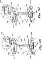
- FIGS. 3A-3Dare a series of perspective views of the docking station forming part of the mobile workstation of FIG. 1 showing the push-down-and-tilt motion used to remove the wireless terminal from the docking station.
- FIGS. 4A-4Bare perspective views of the mobile workstation of FIG. 1 showing the operation of a pull-out keyboard tray.
- FIG. 5Ais a side view of the horizontal tray of the mobile workstation of FIG. 1 showing an access hole and a release lever for raising and lowering the horizontal tray.
- FIG. 5Bis a perspective view of the horizontal tray of the mobile workstation of FIG. 1 showing an access hole and a release lever for raising and lowering the horizontal tray.
- FIG. 6Ais a back view of the horizontal tray and mounting bracket of the mobile workstation of FIG. 1 .
- FIG. 6Bis a reverse view of the mounting bracket of FIG. 6A .
- FIG. 7Ais an exploded view the mounting bracket of FIG. 6A and associated clutch assemblies.
- FIG. 7Bis a side view of a spring washer for the clutch assemblies.
- FIG. 7Cis a perspective view of the spring washer of FIG. 7B .
- FIG. 8illustrates a mobile workstation including a computer terminal and a display screen in a typical environment, such as a patient's hospital room.
- FIGS. 9A-9Dare a series of side views of the mobile workstation of FIG. 8 illustrating the operation of an adjustable-height horizontal tray and a tiltable display screen.
- FIGS. 10A-10Bare perspective views of the mobile workstation of FIG. 8 showing the operation of a pull-out keyboard tray.
- FIG. 11Ais a side view of the horizontal tray of the mobile workstation of FIG. 8 showing an access opening and a release lever for raising and lowering the horizontal tray.
- FIG. 11Bis a perspective view of the horizontal tray of the mobile workstation of FIG. 8 showing an access opening and a release lever for raising and lowering the horizontal tray.
- FIG. 12Ais a perspective view of the mobile workstation of FIG. 8 showing the installation of the wireless computer terminal and the keyboard.
- FIG. 12Bis a side view of the mobile workstation of FIG. 8 showing the installation of the wireless computer terminal, keyboard, and battery pack.
- FIG. 12Cis a front view of the mobile workstation of FIG. 8 showing the installation of the wireless computer terminal and the keyboard.
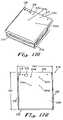
- FIG. 13Ais a perspective view of the horizontal tray and tray housing of the mobile workstation of FIG. 8 .
- FIG. 13Bis a top view of the horizontal tray and mounting bracket of FIG. 13A .
- FIG. 13Cis a front view of the horizontal tray and mounting bracket of FIG. 13A with an installed wireless computer terminal and keyboard.
- FIG. 13Dis a side view of the horizontal tray and mounting bracket of FIG. 13A with an installed wireless computer terminal and keyboard.
- FIG. 14Ais a perspective view of the front mounting bracket of the mobile workstation of FIG. 8 .
- FIG. 14Bis a top view of the front mounting bracket of FIG. 14A .
- FIG. 14Cis a front view of the front mounting bracket of FIG. 14A .
- FIG. 14Dis a side view of the front mounting bracket of FIG. 14A .
- FIG. 15Ais a perspective view of the back mounting bracket of the mobile workstation of FIG. 8 .
- FIG. 15Bis a top view of the back mounting bracket of FIG. 15A .
- FIG. 15Cis a front view of the back mounting bracket of FIG. 15A .
- FIG. 15Dis a side view of the back mounting bracket of FIG. 15A .
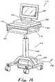
- FIG. 16is a front perspective view of yet another embodiment of a mobile workstation.
- FIG. 17is a rear right side perspective view of the mobile workstation in FIG. 16 .
- FIG. 18is a rear right side perspective view of the mobile workstation in FIG. 16 with a pull-out keyboard tray in the extended position.
- FIG. 19is a front right side perspective view of the mobile workstation in FIG. 16 with the pull-out keyboard tray in the extended position.
- FIG. 20is a side view of the mobile workstation shown in FIG. 16 .
- FIG. 21is a rear perspective view of an alternative embodiment of a mobile workstation with a vital signs capture device.
- FIG. 22is a front perspective view of an alternative embodiment of a mobile workstation with a videoconferencing system.
- the present inventionmay be embodied in a mobile workstation that includes an adjustable-height horizontal tray and a vertically-mounted docking station mounted to the horizontal tray.
- the docking stationremovably supports a computer terminal having a display screen, which may also serve as a touch-sensitive input device, that can be easily seen and accessed when the computer terminal is stored within the docking station.
- the mobile workstationalso includes a keyboard located on a pull-out keyboard tray mounted to the underside of the horizontal tray. The keyboard is connected to the computer terminal by way of the docking station, so that the keyboard is automatically connected to the computer terminal whenever the terminal is stored within the docking station.
- a tiltable bracketmounts the docking station to the horizontal tray.
- a clutch assemblyallows the angle of the bracket, and along with it the angle of the docking station and the computer terminal, to be adjusted to avoid glare on the terminal's display screen.
- a spring-mounted, vertically-movable leveling trayallows the wireless terminal to be easily removed from the docking station using a push-down-and-tilt motion.
- An electronic lockselectively prevents vertical movement of the leveling tray to secure the computer terminal within the docking station.
- the docking stationmay also include a key-operated lock, which may be used to unlock the docking station in the event of a power outage or if the electronic lock should fail.
- the mobile workstationalso carries a power converter and a power unit including an extended-life battery, a battery charger that connects to an AC power supply to charge the conventional battery located inside the computer terminal as well as the extended-life battery carried on the mobile workstation.
- the power converterconverts electrical power supplied by the battery to a suitable electrical input source for the computer terminal and the terminal display.
- the rechargeable battery power supplyincreases the battery life of the computer terminal to about 8-12 hours, which allows use of the computer terminal for an extended time before having to fully recharge it.
- the power unitincludes two status-indicator lights to indicate when the unit is operating on AC power and when the battery is low, and a seven-level battery status-indicator light.
- the power unitmay also include a sensor that indicates when the battery is low.
- the extended-life batteryallows the mobile workstation to be used for an entire shift before recharging.
- the mobile workstationthus eliminates the need for locating a wall-mounted cradle and associated computer terminal outside each patient's room.
- the docking stationis vertically mounted, the computer terminal does not occupy the top surface of the horizontal tray, which allows this area to be used as a work surface.
- the leveling trayallows the computer terminal to be easily removed from, and replaced for storage within, the docking station with one hand.
- the electronic lockallows the docking station to be easily locked and unlocked with one hand.
- a mobile workstationthat includes an adjustable-height horizontal tray on a chassis, a vertically mounted display screen mounted above the horizontal tray, a wireless computer terminal and a power converter mounted underneath the horizontal tray, a pull-out keyboard tray mounted beneath the wireless computer terminal, and a power unit mounted to the chassis.
- the horizontal trayincludes an underside front mounting bracket to support the wireless computer terminal, and a rear mounting bracket to support the power converter.
- the front mounting bracketsupports the wireless computer terminal adjacent to and beneath the horizontal tray, leaving the work surface of the horizontal tray available for other operator uses.
- the back mounting bracket or wiring traysupports the power converter adjacent to and beneath the horizontal tray so that the power converter easily connects to the wireless computer terminal.
- a tray housing mounted to the underside of the horizontal traysupports a pull-out keyboard tray so that a keyboard mounted within the pull-out tray does not interfere with the front mounting bracket or the rear mounting bracket.
- the keyboardcommunicates with the computer terminal through a conventional electrical connection so that the keyboard can be easily connected to the computer terminal whenever the wireless computer terminal is stored within the mobile workstation.
- the wireless computer terminalremovably connects to the display screen that mounts to the top surface of the horizontal tray with a tiltable bracket.
- the mobile workstationalso carries a power unit including an extended-life battery and a battery charger that connects to an AC power supply to charge the conventional battery located inside or adjacent to the wireless computer terminal as well as the extended-life battery carried on the mobile workstation.
- Each batteryconnects to the power converter to supply power to the wireless computer terminal and the terminal display through the power converter.
- the rechargeable battery power supplyincreases the battery life of the computer terminal to about 8-12 hours, which allows use of the computer terminal for an extended time before having to fully recharge it.
- the power unitincludes two status-indicator lights to indicate when the unit is operating on AC power and when the battery is low, and a seven-level battery status-indicator light.
- the power unitmay also include a sensor that indicates when the battery is low.
- Yet another embodiment of the present inventionmay include an adjustable-height horizontal tray on a chassis, a wireless computer terminal mounted above the horizontal tray, a display screen mounted above the wireless computer terminal, a pull-out keyboard tray mounted beneath the horizontal tray, and a power unit mounted to the chassis.
- the horizontal trayincludes a mounting bracket to support the wireless computer terminal above the horizontal tray, leaving the part of the work surface of the horizontal tray available for other operator uses.
- a tray housing mounted to the underside of the horizontal traysupports a pull-out keyboard tray so that a keyboard mounted within the pull-out tray does not interfere with the bottom of the horizontal tray.
- the keyboardcommunicates with the computer terminal through a conventional electrical connection so that the keyboard can be easily connected to the computer terminal whenever the wireless computer terminal is stored within the mobile workstation.
- the wireless computer terminalremovably connects to the display screen that mounts to the top surface of the horizontal tray with a tiltable bracket.
- the mobile workstationalso carries a power converter and a power unit including an extended-life battery and a battery charger that connects to an AC power supply to charge the conventional battery located inside or adjacent to the wireless computer terminal as well as the extended-life battery carried on the mobile workstation.
- Each batteryconnects to the power converter to supply power to the wireless computer terminal and the terminal display through the power converter.
- the rechargeable battery power supplyincreases the battery life of the computer terminal to about 8-12 hours, which allows use of the computer terminal for an extended time before having to fully recharge it.
- the power unitincludes two status-indicator lights to indicate when the unit is operating on AC power and when the battery is low, and a seven-level battery status-indicator light.
- the power unitmay also include a sensor that indicates when the battery is low.
- the extended-life batteryallows the mobile workstation to be used for an entire shift before recharging.
- the mobile workstationthus eliminates the need for locating a wall-mounted cradle and associated computer terminal outside each patient's room.
- the computer terminalWhen the computer terminal is mounted beneath the horizontal tray, the computer terminal does not occupy the top surface of the horizontal tray, which allows this area to be used as a work surface.
- the front mounting bracketallows the computer terminal to be easily removed from, and replaced for storage within, the front mounting bracket.
- the computer terminaldoes not occupy the entire top surface of the horizontal tray, which allows the remaining area to be used as a work surface.
- the mounting bracket above the horizontal trayallows the computer terminal to be easily removed from, and replaced for storage within, the mounting bracket.
- the wireless computer terminal in a mobile workstationcan also communicate through a radio-frequency communication channel via a radio transmitter/receiver terminal antenna attached to the top of the horizontal tray. In this manner, the wireless computer terminal can exchange information with a computer network, such as a distributed patient-care computer network.
- a computer networksuch as a distributed patient-care computer network.
- the mobile workstationcould be configured to support a device other than a docking station or a wireless computer terminal, such as a medical instrument.
- the mobile workstationcould be configured to support an ultra-sound device used to view a fetus.
- the docking station or the wireless computer terminalcould be removed from the mobile workstation, and a similarly sized ultra-sound device could be placed within the mobile workstation.
- the patientcould then view the display screen of the mobile workstation to see the results of the ultra-scan procedure.
- Many other applications, both medical and non-medical,will become apparent to those skilled in the art from the examples described in this specification.
- FIG. 1illustrates a mobile workstation 10 in a typical environment, such as a patient's hospital room 5 .
- the mobile workstation 10includes an adjustable-height horizontal tray 12 supported by a chassis 14 .
- the chassis 14includes a dolly assembly 16 that allows an operator, such as a medical practitioner, to easily push the mobile workstation 10 from place to place.
- the horizontal tray 12supports a docking station 18 that, in turn, removably supports a device, such as the wireless computer terminal 20 with a terminal display screen.
- the chassis 14includes a vertical beam 22 connecting the horizontal tray 12 to the dolly assembly 16 .
- the vertical beam 22includes a gas-spring height adjustment mechanism for adjusting the length of the beam and, thus, the height of the horizontal tray 12 above the dolly assembly 14 .
- the chassis 14may be a model MPC2001 manufactured by JACO, Inc. with the standard tray replaced by the horizontal tray 12 shown in FIG. 1 .
- JACO, Inc.JACO, Inc.
- other types of wheeled chassiswould be suitable for this purpose.
- other types of height adjustment mechanismswould also be suitable, such as a rack and pinion mechanism, a cable and pulley mechanism, a ratchet mechanism, a ball screw mechanism, a removable pin and holes arrangement, and so forth.
- a gas-spring height adjustment mechanismis preferred because it is easy operate and ergonomically desirable.
- the mobile workstation 10also carries a power unit 24 including a power converter, a battery charger, an extended-life battery, a power cord 26 , and a recoil mechanism that automatically recoils the power cord when the cord is not plugged into an AC outlet.
- the power converterconverts power received from the power unit 24 to suitable power for the wireless computer terminal 20 .
- the power unit 24is located on the lower end of the chassis 14 .
- the power unit 24may reside between two metal beams in the dolly assembly 16 at the lower end of the chassis 14 .
- the extended-life batterymay be a 12-Volt sealed lead acid battery, and the power supply may be a 120-Volt AC to 16-Volt DC converter.
- the power unit 24typically includes a first status-indicator light to inform the user when the unit is running on AC power, a second status-indicator light to inform the user when the battery needs recharging, and a seven-level battery status-indicator light to inform the user about the power status of the battery.
- the power unit 24may also include an alarm or audible indicator to inform the user when the extended-life battery power needs recharging.
- the extended-life batterycan be recharged by connecting the plugging the power cord 26 into a standard 120-volt AC outlet. When not in use, the recoil mechanism retracts the power cord 26 into the power unit 24 .
- the wireless computer terminal 20typically includes a radio transmitter/receiver antenna for communicating over an approved radio frequency.
- the wireless computer terminal 20may establish a radio-frequency communication channel 28 with a distributed patient-care computer network 30 through an antenna 32 connected to a network access point 34 .
- This network access pointis typically located in an enclosure 36 located above the ceiling of the hospital room.
- the network access point 34allows the wireless computer terminal 20 to communicate with the distributed patient-care computer network 30 .
- the network access point 34may be a RANGELAN2 7500 Series Access Point manufactured by PROXIM, INC. of Mountain View, Calif.
- FIGS. 2A-2Dare a series of side views of the mobile workstation 10 illustrating the operation of an adjustable-height horizontal tray 12 and the tiltable docking station 18 .
- FIG. 2Ashows the mobile workstation 10 with the height-adjustable horizontal tray 12 in a vertically lowered position. To raise the tray, the operator places his or her hand through an opening 40 in the side of the horizontal tray 12 . The operator then lifts a release lever 42 , which releases a stop in the gas-spring height adjustment mechanism in the vertical beam. The operator then raises or lowers the horizontal tray 12 while holding the release lever 42 in a raised position.
- Assistance provided by the gas-spring height adjustment mechanismallows the operator to change the height of the horizontal tray 12 with little effort. Once the horizontal tray 12 is at a desired height, represented by the height shown in FIG. 2B , the operator releases the lever 42 , which locks the tray at the desired height. With this type of mechanism, the operator can quickly and easily place the horizontal tray 12 at virtually any height within the adjustment range of the gas-spring height adjustment mechanism.
- the assistance provided by the gas-spring height adjustmentis ergonomically desirable in that it avoids back strain or other lifting problems that could otherwise be encountered by operators using the mobile workstation 10 .
- FIG. 2Cillustrates the mobile workstation 10 with the docking station 18 in a vertical position.
- a tiltable bracket 44attaches the docking station 18 to the horizontal tray 12 .
- a clutch 46 in the tiltable bracketmaintains the docking station 18 in a number of selectable rotational positions relative to the tray 12 .
- the rotational range of the tiltable bracket 44is preferably about 30 degrees rearward from vertical. That is, the tiltable bracket 44 preferably allows the docking station 18 to be rotated from the position shown in FIG. 2C to the position shown in FIG. 2D .
- the tiltable bracket 44could also be configured to allow the docking station 18 to rotate forward through a similar rotational range.
- the term “substantially vertical”may include a range about a strictly vertical orientation, represented by the 30 degree range illustrated by FIGS. 2C-D .
- the term “substantially vertical”includes configurations in which the bracket 44 maintains the docking station 18 in a strictly vertical orientation, or at a fixed rotational orientation with a vertical component, or within a range of rotational orientations including orientations that include vertical components.
- the docking station 18could be supported in a substantially horizontal position, for example by a drawer or pull-out tray located above or under the horizontal tray 12 . Other locations for the docking station 18 may be preferred in certain environments.
- the docking stationcould be mounted to the side of the horizontal tray 12 , to the underside of the horizontal tray 12 , to the dolly assembly 16 , to the vertical beam 22 , and so forth.
- the clutch 46imparts sufficient rotational resistance to maintain the docking station 18 , with an associated computer terminal 20 , at any of the rotational aspects within the rotational range defined by the tiltable bracket 44 .
- the rotational resistance imparted by the clutch 46is pliant enough to allow the operator to change the rotational orientation of the docking station 18 with one hand. For example, the operator may easily adjust the angle of the docking station 18 to avoid glare on the display screen of the computer terminal 20 .
- the tiltable bracket 44 and the clutch 46are described in greater detail with reference to FIGS. 6A-B and 7 A-C below.
- FIGS. 3A-3Dare a series of perspective views of the docking station 18 and an associated wireless computer terminal 20 showing the push-down-and-tilt motion used to remove the terminal from the docking station.
- the docking station 20includes a base 50 , a back plane 52 , and two spaced-apart retaining arms 54 and 56 . When the computer terminal 20 is located in the docking station, the retaining arms 54 and 56 support the top side 62 of the terminal.
- the base 50includes a leveling tray 58 with a rubber cushion 60 for receiving the bottom side of the computer terminal 20 .
- the rubber cushion 60includes raised collars on either end that prevent the computer terminal 20 from being removed from the docking station 18 when the leveling tray 58 is locked in the upper position, as shown in FIG. 3A .
- the docking station 18includes a control panel 62 having a keypad 64 , typically with four keys.
- the docking station 18may be configured so that the keypad 64 operates as an electronic combination lock.
- the leveling tray 58can be depressed when the docking station is unlocked and, when the docking station 18 is locked, the leveling tray 58 cannot be depressed.
- the docking station 18may also include a manual key lock that may be used to lock and unlock the docking station in the event of a power outage or a malfunction of the electronic lock.
- the control panel 62may also include status lights 64 a - c that indicate status information regarding the docking station 18 .
- these status lightstypically indicate whether the docking station is locked, whether power is on, and provide status information while a user is configuring the docking station with passwords.
- a touch-pin battery charging terminal 68 or other conventional electrical connection located in the leveling tray 58may be used to charge a battery within the computer terminal 20 while the terminal is stored within the docking station 18 .
- This battery charging terminalis connected to the power unit 24 .
- the power unitincludes the power cord 26 , which may be plugged into a standard 120 Volt AC outlet.
- the docking station 18may include a communication interface, such as an optical interface, for communicating data between the computer terminal 20 and the docking station 18 while the terminal is stored within the docking station. This allows the computer terminal 20 to communicate with the keypad 64 and/or an optional keyboard that plugs into the docking station 18 .
- a communication interfacesuch as an optical interface
- an operatorTo remove the computer terminal 20 , an operator first unlocks the docking station 18 and then places his or her hand on the top side 62 of the terminal and pushes downward. Provided that the docking station 18 is unlocked, this motion depresses the leveling tray 58 , as shown in FIG. 3B . The operator then tilts the terminal 20 forward, as shown in FIG. 3C , and removes the terminal 20 , as shown in FIG. 3D .
- An example of a suitable docking stationis described in commonly owned U.S. patent application Ser. No. 08/841,496, entitled “Cradle For Holding A Device,” filed Apr. 23, 1997, which is incorporated into this specification by reference.
- FIGS. 4A-Bare perspective views of the mobile workstation 10 showing the operation of a pull-out keyboard tray 70 , which is supported by the underside of the horizontal tray 12 .
- the pull-out keyboard tray 70slides from an inner position, shown in FIG. 4A , to an outer position, shown in FIG. 4B .
- a keyboard mounted on the keyboard tray 70typically plugs into the docking station 18 , which communicates keystrokes with the computer terminal 20 by way of a conventional electrical connection. This allows an operator to easily remove the computer terminal 20 from the docking station 18 .
- FIGS. 4A-4Bthe top portion of a rectangular cover for the vertical beam 22 has been removed, showing an underlying shaft 72 and a power cable 73 connecting the power unit 24 to the docking station 18 .
- This shaft 72connects to the gas-spring height adjustment mechanism 74 that allows adjustment of the height of the horizontal tray 12 .
- the gas-spring height adjustment mechanism 74which is located at the bottom of the vertical beam 22 , sits on top of the dolly assembly 16 .
- This dolly assemblyincludes an arched cross-beam 76 that connects to two horizontal runner beams 78 a - b .
- Two casters, represented by the caster 80are connected to the bottom sides of each horizontal runner beam 78 a - b .
- the power unit 24is mounted below the arched cross beam 76 to an arched support plate 82 , which connects between the horizontal runner beams 78 a - b.
- FIGS. 4A-Balso show that the top side of the horizontal tray 12 defines a substantially horizontal work surface 86 , which is bordered by a raised edge guard 88 .
- the rear edge of the horizontal tray 12includes a recess 90 for the docking station 18 , which defines an elongate dimension 92 and a relatively slender dimension 94 . That is, the docking station 18 is substantially taller than it is thick.
- the tiltable mounting bracket 44supports the docking station 18 so that the elongate dimension 92 is substantially vertical and the relatively slender dimension 94 is substantially horizontal. Because the docking station 18 is vertically mounted, the terminal 20 does not occupy the top surface 86 of the horizontal tray 12 , which allows this area to be used as a work surface.
- the computer terminal 20typically includes a display screen 96 , and the docking station 18 supports the terminal with the display screen substantially perpendicular to and above the top surface 86 of the horizontal tray 12 for easy viewing.
- substantially perpendicularincludes a range of orientations because the docking station 18 may rotate through a rotational range about a strictly perpendicular orientation.
- FIG. 5Ais a side view of the horizontal tray 12 showing the access hole 40 and the release lever 42 for raising and lowering the horizontal tray 12 .
- the release lever 42operates the gas-spring height adjustment lever, which is shown best in FIG. 4A .
- FIG. 5Aalso shows the end of the pull-out keyboard tray 70 , which includes a lip 98 to aid in pulling the keyboard tray out and pushing it back in.
- FIG. 5Bis a perspective view of the horizontal tray 12 showing the access hole 40 and the release lever 42 for raising and lowering the horizontal tray 12 .
- FIG. 5Balso shows the top surface 86 , the edge guard 88 , and the recess 90 of the horizontal tray 12 .
- the top surface 86 of the horizontal tray 12is preferably constructed from a non-porous material, such as plastic or metal.
- the horizontal tray 12may be constructed from a flat wooden, particle board, or composite substrate covered with a plastic overlay defining the top surface 86 and the edge guard 88 .
- the plastic overlaymay be created with an injection mold, and then glued to the substrate.
- the bracket 44includes mounting brackets 102 a - b and a back plane 100 supporting the docking station.
- the back plane 100may be formed from a heavy gauge sheet metal, fiberglass, or composite.
- the sides 103 and bottom 104 the horizontal tray 12may be formed from sheet metal.
- FIG. 6Ais a back view
- FIG. 6Bis a reverse view, of the horizontal tray 12 showing the tiltable bracket 44 , including the back plane 100 and mounting brackets 102 a - b .
- the mounting brackets 102 a - bare bolted to the rear side of the horizontal tray 12 and extend into the recess 90 so that the back plane 100 is approximately flush with the rear side of the horizontal tray 12 when the back plane is in a vertical position.
- the mounting brackets 102 a - beach include an arcuate slot 106 a - b to allow the back plane 100 to rotate through a rotational range with respect to the mounting brackets. For example, that rotational range is approximately 30 degrees in the configuration shown in FIGS. 6A-B .
- FIG. 7Ais an exploded view the mounting brackets 102 a - b and the clutch assemblies 46 a - b .
- this assemblyincludes two identical connection assemblies 110 a - b .
- this assemblyincludes a threaded standoff 112 including a collar that passes through a hole in the support frame 114 of the back plane 100 and a rim that catches on the support frame.
- the threaded standoff 112is preferably press-fitted into the hole in the support frame 114 .
- the connection assembly 110 aalso includes a nylon shoulder washer 116 including a collar that passes through a hole in the mounting bracket 44 b and a rim that catches on the mounting bracket.
- the collar of nylon shoulder washer 116is sized to snugly receive the threaded standoff 112 .
- the connection assembly 110 aalso includes a nylon washer 118 , two steel washers 120 and 122 , and a steel spring washer 124 positioned for compression between the steel washers.
- a bolt 126passes through these washers and screws into the threaded standoff 112 .
- the bolt 126may be tightened into the threaded standoff 112 to compress the steel spring washer 124 and provide a desired amount of resistance in the connection assembly 110 a.
- FIG. 7Bis a side view of the spring washer 124
- FIG. 7Cis a perspective view of the spring washer.
- FIG. 8illustrates a mobile workstation 210 in a typical environment, such as a patient's hospital room 205 .
- the mobile workstation 210includes an adjustable-height horizontal tray 212 supported by a chassis 214 .
- the chassis 214includes a dolly assembly 216 that allows an operator, such as a medical practitioner, to easily push the mobile workstation 210 from place to place.
- the horizontal tray 212includes an underside tray housing 218 , an underside front mounting bracket 220 , and an underside back mounting bracket 222 or wiring tray.
- the tray housing 218supports a keyboard (not shown) or keypad for a wireless computer terminal (not shown).
- the wireless computer terminalmounts within the front mounting bracket 220 .
- the back mounting bracket 222 or wiring traysupports a power converter (not shown) supplying power to the wireless computer terminal.
- a tiltable display screen 224attaches to the top of the horizontal tray 212 while connecting to the wireless computer terminal.
- the back mounting bracket 222 or wiring traycan also support additional power converters for the display screen 224 or for other electrical devices associated with the mobile workstation 210 .
- the chassis 214includes a vertical beam 226 connecting the horizontal tray 212 to the dolly assembly 216 .
- the vertical beam 226includes a gas-spring height adjustment mechanism (not shown) and a release lever 228 for adjusting the length of the beam 226 and, thus, the height of the horizontal tray 212 above the dolly assembly 216 .
- the chassis 214may be a model MPC2001 manufactured by JACO, Inc. with the standard tray replaced by the horizontal tray 212 shown in FIG. 8 .
- JACO, Inc.JACO, Inc.
- a rack and pinion mechanismsuch as a rack and pinion mechanism, a cable and pulley mechanism, a ratchet mechanism, a ball screw mechanism, a removable pin and holes arrangement, and so forth.
- a gas-spring height adjustment mechanism 228is preferred because it is easy operate and ergonomically desirable.
- the mobile workstation 210also carries a power converter (not shown) within the back mounting bracket 222 and a power unit 230 including a battery charger, an extended-life battery, a power cord 232 , and a recoil mechanism that can retract the power cord when the cord is not in use.
- the power unit 230supplies power to the wireless computer terminal through the power converter.
- the power unit 230is located on the lower end of the chassis 214 .
- the power unit 230may reside between two metal beams in the dolly assembly 216 at the lower end of the chassis 214 .
- a suitable power unit 230is a 26 Amp-Hour battery providing a regulated 10-16 Volt output at 40 watts with an automatic low power cut-off.
- the extended-life batterymay be a 12-Volt sealed lead acid battery, and the battery charger may be a 120-Volt AC to 16-Volt DC converter.
- the power unit 230typically includes a first status-indicator light to inform the user when the unit is operating off of AC power, a second status-indicator light to inform the user when the battery needs recharging, and a seven-level battery status-indicator light.
- the power unit 230may also include a sound indicator that beeps to inform the user when the extended-life battery needs recharging.
- the battery chargerWhen plugged into an AC outlet, the battery charger will charge both the extended-life battery and operate the wireless computer terminal by supplying the power converter connected to the computer terminal.
- the extended-life batterycan be recharged by plugging the power cord 232 into a standard 120-volt AC outlet. When not in use, the recoil mechanism can retract the power cord 232 into the power unit 230 .
- the wireless computer terminal inside the mobile workstation 210communicates through a radio transmitter/receiver terminal antenna 234 attached to the top of the horizontal tray 212 .
- the terminal antenna 234is operable for communicating over an approved radio frequency.
- a suitable radio transmitter/receiver to mount to the wireless computer terminalis a Lucent Extended 802.11 radio with a cable for using an external antenna.
- a suitable terminal antenna 234 for mounting to the horizontal tray 212is a whip antenna used in DOS VMT products (1380/1390, 1320/1330).
- the wireless computer terminalmay establish a radio-frequency communication channel 236 with a distributed patient-care computer network 238 through an antenna 240 connected to a network access point 242 .
- This network access point 242is typically located in an enclosure 244 located above the ceiling of the hospital room.
- the network access point 242allows the wireless computer terminal to communicate with the distributed patient-care computer network 238 .
- the network access point 242may be a RANGELAN2 7500 Series Access Point manufactured by PROXIM, INC. of Mountain View, Calif.
- FIGS. 9A-9Dare a series of side views of the mobile workstation 210 illustrating the operation of an adjustable-height horizontal tray 212 and the display screen 224 .
- FIG. 9Ashows the mobile workstation 210 with the height-adjustable horizontal tray 212 in a vertically lowered position.
- the operatorplaces his or her hand through an access opening 246 in the side of the tray housing 218 .
- the operatorthen lifts the release lever 228 , which releases a stop in the gas-spring height adjustment mechanism (not shown) in the vertical beam 226 .
- the operatorthen raises or lowers the horizontal tray 212 while holding the release lever 228 in a raised position.
- Assistance provided by the gas-spring height adjustment mechanismallows the operator to change the height of the horizontal tray 212 with little effort. Once the horizontal tray 212 is at a desired height, represented by the height shown in FIG. 9B , the operator releases the lever 228 , which locks the tray 212 at the desired height. With this type of mechanism, the operator can quickly and easily place the horizontal tray 212 at virtually any height within the adjustment range of the gas-spring height adjustment mechanism.
- the assistance provided by the gas-spring height adjustmentis ergonomically desirable in that it avoids back strain or other lifting problems that could otherwise be encountered by operators using the mobile workstation 210 .
- FIG. 9Cillustrates the mobile workstation 210 with the display screen 224 in a vertical position.
- a tiltable bracket 248attaches the display screen 224 to the horizontal tray 212 .
- the tiltable bracket 248maintains the display screen 224 in a number of selectable rotational positions relative to the tray 212 so that the display screen 224 is in front of users for ease of visibility.
- the rotational range of the tiltable bracket 248is preferably about 30 degrees rearward from vertical. That is, the tiltable bracket 248 preferably allows the display screen 224 to be rotated from the position shown in FIG. 9C to the position shown in FIG. 9D .
- the tiltable bracket 248could also be configured to allow the display screen 224 to rotate forward through a similar rotational range.
- the term “substantially vertical”may include a range about a strictly vertical orientation, represented by the 30 degree range illustrated by FIGS. 9C-9D .
- the term “substantially vertical”includes configurations in which the bracket 248 maintains the display screen 224 in a strictly vertical orientation, or at a fixed rotational orientation with a vertical component, or within a range of rotational orientations including orientations that include vertical components.
- the display screen 224could be supported in a substantially horizontal position, for example by a drawer or pull-out tray located above or under the horizontal tray 212 . Other locations for the display screen 224 may be preferred in certain environments.
- the display screen 224could be mounted to the side of the horizontal tray 212 , to the underside of the horizontal tray 212 , to the dolly assembly 216 , to the vertical beam 226 , and so forth.
- the tiltable bracket 248imparts sufficient rotational resistance to maintain the display screen 224 , with an associated computer terminal (not shown), at any of the rotational aspects within the rotational range defined by the tiltable bracket 248 .
- the rotational resistance imparted by the tiltable bracket 248is pliant enough to allow the operator to change the rotational orientation of the display screen 224 with one hand. For example, the operator may easily adjust the angle of the display screen 224 to avoid glare on the display screen 224 .
- a clutch mechanism similar to that discussed with reference to FIG. 7may be used to allow selective rotation of the display screen 224 .
- FIGS. 10A-10Bare perspective views of the mobile workstation 210 showing the operation of a pull-out keyboard tray 250 , which is supported by the tray housing 218 attached to the underside of the horizontal tray 212 .
- the pull-out keyboard tray 250slides from an inner position, shown in FIG. 10A , to an outer position, shown in FIG. 10B , along conventional rollers (not shown) within a conventional roller guide slots (not shown).
- rollers mounted to the bottom side of the keyboard tray 250fit within roller guide slots attached to the top side of the tray housing 218 .
- a keyboard(not shown) fits within the pull-out keyboard tray 250 .
- the pull-out keyboard tray 250is to detent when fully extended away from the front edge of the tray housing 218 , permitting the operator to type on the keyboard without the keyboard tray 250 sliding back into the tray housing 218 .
- the pull-out keyboard tray 250is in the retracted position, the keyboard tray 250 will not slide out during movement or transport of the mobile workstation 210 .
- the pull-out keyboard tray 250can be extended outward from the front end of the tray housing 218 .
- the rollers on the bottom of the pull-out keyboard tray 250permit the pull-out tray 250 to roll forward within the roller guide slots along the length of the top side of the tray housing 218 .
- the roller guide slotshave a physical stop at the front end of the tray housing 218 . When a roller makes contact with the physical stop at the front end of the tray housing 218 , the pull-out keyboard tray 250 cannot be extended any further from the front edge of the tray housing 218 .
- FIGS. 10A-10Bthe top portion of a rectangular cover for the vertical beam 226 has been removed, showing an underlying shaft 252 and a power cable 254 connecting the power unit 230 to the power converter (not shown).
- This shaft 252connects to the gas-spring height adjustment mechanism 256 that allows adjustment of the height of the horizontal tray 212 .
- the gas-spring height adjustment mechanism 256which is located at the bottom of the vertical beam 226 , sits on top of the dolly assembly 216 .
- This dolly assemblyincludes an arched cross-beam 258 that connects to two horizontal runner beams 260 a - b .
- Two castersare connected to the bottom sides of each horizontal runner beam 260 a - b .
- a suitable size casteris a conventional 5′′ caster.
- the power unit 230is mounted below the arched cross beam 258 with a support bracket 264 , which connects between the horizontal runner beams 260 a - b.
- FIGS. 10A-10Balso show that the top side 266 of the horizontal tray 212 defines a substantially horizontal work surface.
- the tiltable bracket 248supports the display screen 224 so that the elongate dimension 268 is substantially vertical and the relatively slender dimension 270 is substantially horizontal. Because the display screen 224 is vertically mounted, the display screen 224 does not occupy a substantial portion of the top surface 266 of the horizontal tray 212 , which allows this area to be used as a work surface. It will be understood that the term “substantially vertical” includes a range of orientations because the display screen 224 may rotate through a rotational range about a strictly perpendicular orientation.
- FIG. 11Ais a side view of the horizontal tray 212 and the attached tray housing 218 showing the access opening 246 and the release lever 228 for raising and lowering the horizontal tray 212 .
- the release lever 228operates the gas-spring height adjustment mechanism 256 previously shown in FIGS. 10A-10B .
- the access opening 246 in the side wall of the tray housing 218provides convenient operator access to actuate the release lever 228 .
- FIG. 11Bis a perspective view of the horizontal tray 212 showing the access opening 246 and the release lever 228 for raising and lowering the horizontal tray 212 .
- the release lever 228has a tee or a paddle on the end, so that an operator can conveniently actuate the release lever 228 thereby raising or lowering the gas-spring height adjustment mechanism 256 .
- FIG. 11Balso shows the top surface 266 of the horizontal tray 212 .
- the top surface 266 of the horizontal tray 212is preferably constructed from a non-porous material, such as plastic or metal.
- the horizontal tray 212may be constructed from a flat wooden, particle board, or composite substrate covered with a plastic overlay defining the top surface 266 .
- the plastic overlaymay be created with an injection mold, and then glued to the substrate.
- FIGS. 12A-12Care a series of detailed views of the mobile workstation 210 of FIG. 8 , with the display screen 224 , a keyboard 272 , a wireless computer terminal 274 , and a power unit 230 .
- FIG. 12Ais a perspective view of the mobile workstation 210 illustrated in FIG. 8 .
- FIG. 12Bis a side view of the mobile workstation 210 illustrated in FIG. 12A .
- FIG. 12Cis a front view of the mobile workstation 210 illustrated in FIG. 12A .
- the mobile workstation 210is shown with a display screen 224 mounted to the top surface of the horizontal tray 212 .
- a tiltable bracket 248connects the display screen 224 to the top of the horizontal tray 212 .
- Conventional electrical connections(not shown) provide an interface between the wireless computer terminal 274 and the display screen 224 .
- a suitable display screen 224is a flat panel LCD with a 14-15′′ TFT viewable screen, a minimum video resolution of 1024 ⁇ 768 pixels, a minimum 200 nit, and a DC power input.
- Those skilled in the artwill appreciate that other types of display screens could be employed in embodiments of the invention, including those having touch performance screens.
- a front mounting bracket 220mounts to the bottom side 278 of the horizontal tray 212 , and holds the computer terminal 274 substantially parallel to the bottom side 278 of the front portion of the horizontal tray 212 .
- the front mounting bracket 220is sized to support the wireless computer terminal 274 , such as a laptop computer, within the front bracket 220 and adjacent to the bottom side of the horizontal tray 212 .
- the front mounting bracket 220has an access window 280 in the side wall for operator access to various ports or interfaces in the side of the wireless computer terminal 274 .
- the wireless computer terminal 274may include a communication interface, such as an optical interface or a conventional electrical connection, for communicating data between the computer terminal 274 and the keyboard 272 .
- the communication interface between the keyboard 272 and the computer terminal 274allow the keyboard 272 to communicate keystrokes to the computer terminal 274 .
- This type of operationpermits an operator to easily remove the computer terminal 274 from the front mounting bracket 220 , or to remove the keyboard 272 from the keyboard tray 250 .
- the wireless computer terminal 274can then send signals through the terminal antenna 234 attached to the top surface 266 of the horizontal tray 212 to communicate with a remote computer network (shown in FIG. 8 as 238 ) via a radio frequency communication channel (shown in FIG. 8 as 236 ).
- a suitable wireless computer terminalis an Orion PC manufactured by Netier Technologies.
- the variety of computer terminal models offered under the Orion PC familyincludes a “Thin Client” configuration, or a “Fat” system.
- the “Fat” systemcomprises an ACD-MSX-100 base unit with a Pentium 266 MHz microprocessor on a Socket 7 motherboard operating a MICROSOFT Windows 95 operating system, 32-128 MB RAM, 2 MB Video RAM, 2 GB hard disk, two Type II PCMCIA slots, one Type III PCMCIA slot, one parallel port, one serial port, one video port, one LCD port, dual USB ports, one PS/2 keyboard/mouse port, one IrDa port, and one battery module.
- Optional accessories for the Orion PC familyinclude an automobile cigarette lighter charger/adaptor, and AC charger/adaptor, a second battery module, a floppy disk drive, and a CD-ROM or CD-R drive.
- a second battery modulefor the Orion PC family
- a floppy disk drivefor the Orion PC family
- CD-ROM or CD-R drivefor the Orion PC family
- Those skilled in the artwill appreciate that other computer terminals can be used in conjunction with the present invention to achieve the same purpose.
- a suitable keyboard for use with the wireless computer terminalis a thin Cherry keyboard with a PS/2 interface.
- An optional plastic keyboard coverprotects the keyboard from spills during usage.
- Other computer interfaces for the wireless computer terminalinclude a PSC Q6000 scanner with a PS/2 interface, a serial mouse, and a Y-cable to merge the keyboard and the scanner inputs.
- a conventional electrical connection(not shown) between the wireless computer terminal 274 and the power converter provides an interface between the computer terminal 274 and the power converter.
- Conventional electrical connectionssuch an automobile adaptor plug, or a touch-pin battery charging terminal can be used with a wireless computer terminal 274 to provide an interface with the power converter within the back mounting bracket 222 .
- the power converteris connected to the power unit 230 by the power cable (shown in FIG. 10A as 254 ).
- the power unit 230can then be plugged into a standard 120 Volt AC outlet with the power cord 232 .
- the back mounting bracket 222 or wiring trayalso mounts to the bottom side 278 of the horizontal tray 212 .
- the back mounting bracket 222 or wiring traysupports the power converter substantially parallel to and adjacent to the bottom side 278 of the horizontal tray 212 .
- the power converteris supported within the sidewalls of the back mounting bracket 222 , which can further support cables (not shown) for other devices connected to the computer terminal 274 , such as a mouse, keypad, or other similar devices, or support other power converters for other electrical devices associated with the mobile workstation 210 .
- a series of ventilation holes 282 machined in the sidewall of the back mounting bracket 222assist in venting heat away from the power converter mounted within the back bracket 222 .
- the tray housing 218is also attached the bottom side 278 of the horizontal tray 212 .
- the tray housing 218is sized to fit over the front mounting bracket 220 and the back mounting bracket 222 leaving sufficient clearance between the topside of the tray housing 218 and both the front bracket 220 and the back bracket 222 .
- Sufficient clearance between the tray housing 218 and the front mounting bracket 220permits the installation of a keyboard 272 or keypad within the pull-out keyboard tray 250 in the tray housing 218 , so that the keyboard 272 does not interfere with the bottom of the front mounting bracket 220 when the pull-out keyboard tray 250 is fully retracted within the tray housing 218 as shown.
- the access opening 246 in the side wall of the tray housing 218permits operator access to various ports or interfaces on the side of the wireless computer terminal 274 through the access window 280 of the front mounting bracket 220 .
- the size of the access opening 246also permits operator access to actuate the release lever 228 of the gas spring height adjustment mechanism (shown in FIG. 10A as 256 ) to raise or lower the height of the mobile workstation 210 as shown in FIGS. 9A-9B and FIGS. 11A-11B .
- FIG. 12Bshows the pull-out keyboard tray 250 in a retracted position within the tray housing 218 .
- the display screen 224 of the mobile workstation 210is shown in a substantially vertical orientation to the horizontal tray 212 . In this configuration, an operator can transport the mobile workstation 210 from one area to another area, or use the top surface 266 of the horizontal tray 212 as a work surface.
- the length 284 of the horizontal runner beams 260 a - bis approximately 21.3 inches.
- FIG. 12Cshows a front view of the mobile workstation 210 in FIG. 12A .
- the computer terminal 274is shown mounted within the front mounting bracket 220 and above the keyboard 272 mounted within the pull-out keyboard tray 250 .
- the height 286 from the top surface 266 of the horizontal tray 212 to the flooris approximately 38.6 inches when the tray 212 is in the lowermost position.
- the height 288 from the top edge of the display screen 224 in a fully vertical orientation to the flooris approximately 54.5 inches when the tray 212 is in the lowermost position.
- the width 290 between the outboard ends of the horizontal runner beams 260 a - bis approximately 21.4 inches.
- Other heights 286 , 288 for the horizontal tray 212 and the display screen 224can be attained when the mobile workstation is adjusted for ease of accessibility and visibility.
- FIGS. 13A-13Dillustrate a series of views of the horizontal tray 212 of the mobile workstation 210 of FIG. 8 with an attached tray housing 218 , front mounting bracket 220 , back mounting bracket 222 , and pull-out keyboard tray 250 .
- FIG. 13Ashows a perspective view of the horizontal tray 212 shown in FIG. 8 , with an attached tray housing 218 extending from the bottom side of the horizontal tray 212 .
- FIG. 13Bshows the top view of the horizontal tray 212 .
- the top surface of the horizontal tray 212is rectangular in shape with rounded edges at the front side 292 , the left side 294 , and right side 296 .
- the rear side 298 of the horizontal tray 212has a square edge.
- the width 300 of the horizontal tray 212 from the left side 294 to the right side 296is approximately 18.0 inches.
- the depth 302 of the horizontal tray 212 from the front edge 292 to the rear edge 298is approximately 19.4 inches.
- a series of four mounting holes 304 a - dis machined into the rear portion of the top surface 266 of the horizontal tray 212 to correspond with a set of mounting bolts (not shown) used to secure the base of the tiltable bracket (shown in FIGS.
- a first hole 306 in the left rear portion of the top surface 266 of the horizontal tray 212provides access for the display screen cables (not shown) to extend from the display screen 224 to the computer terminal 274 underneath the horizontal tray 212 .
- a second hole 308 machined in the left rear portion of the horizontal tray 212provides a mount for the terminal antenna 234 permitting the wireless computer terminal 274 to communicate with a computer network (shown in FIG. 8 as 238 ) via radio frequency communication channel (shown in FIG. 8 as 236 ).
- FIG. 13Cshows the front view of the horizontal tray 212 shown in FIG. 13A , with a wireless computer terminal 274 within the front mounting bracket 220 , and a keyboard 272 within the pull-out keyboard tray 250 mounted to the tray housing 218 .
- Each side wall 310 a - b of the tray housing 218curves inward at the top portion of the side wall providing a mounting lip 312 a - b to attach the tray housing 218 to the bottom side 278 of the horizontal tray 212 .
- Holes(not shown) are machined in the mounting lip 312 a - b to correspond with bolts (not shown) to attach the tray housing 218 securely to the bottom side 278 of the horizontal tray 212 .
- a pull-out keyboard tray 250is supported between the side walls 310 a - b of the tray housing 218 and substantially parallel to the top side of the tray housing 218 .
- the pull-out tray 250can be extended or retracted from the front of the tray housing 218 .
- conventional rollers (not shown) mounted on the bottom of the pull-out tray 250correspond with guide slots (not shown) mounted or machined into the top side of the tray housing 218 .
- the keyboard 272fits within the pull-out keyboard tray 250 so that the keyboard 272 does not interfere with the front mounting bracket 220 when the pull-out keyboard tray 250 is retracted within the tray housing 218 .
- FIG. 13Dshows a side view of the horizontal tray 212 shown in FIG. 13A , with an attached tray housing 218 , front mounting bracket 220 , back mounting bracket 222 or wiring tray, and pull-out keyboard tray 250 .
- the front mounting bracket 220mounts towards the front portion of the horizontal tray 212 , providing operator access to the computer terminal 274 from the front edge 292 of the horizontal tray 212 .
- the back mounting bracket 222 or wiring traymounts towards the rear portion of the horizontal tray 212 , flush with the rear edge 298 of the bottom side 278 of the horizontal tray 212 .
- the tray housing 218mounts near the front edge of the bottom side 278 of the horizontal tray 212 , substantially overlapping the front mounting bracket 220 and partially overlapping the back mounting bracket 222 .
- the access opening 246 in the side wall of the tray housing 218permits operator access to the various ports or interfaces in the side of the wireless computer terminal 274 through the access window 280 of the front mounting bracket 220 .
- the height 314 of the horizontal tray 212 with the attached tray housing 218 measured from the top surface 266 of the horizontal tray 212 to the bottom side of the tray housing 218is approximately 4.7 inches.
- FIGS. 14A-14Dillustrate the details of the front mounting bracket 220 shown in FIG. 8 .
- FIG. 14Ashows a perspective view of a front mounting bracket 220 .
- the front mounting bracket 220is sized to receive a wireless computer terminal 274 between two side walls 316 a - b and on the top surface 318 of the front bracket 220 .
- Each side wall 316 a - b of the front bracket 220is shaped with a mounting lip 320 a - b extending along the top of each side wall 316 a - b for mounting the front bracket 220 to the bottom surface 278 of the horizontal tray 212 .
- Two bolt holes 322 a - dare machined through each mounting lip 320 a - b to receive bolts (not shown) attaching the front bracket 220 to the bottom surface 278 of the horizontal tray 212 .
- Access windows 324 , 326are cut into each side wall 316 a - b of the front bracket 220 to permit user access to the ports or interfaces on each side of the wireless computer terminal 274 .
- An elongated access opening 328 along the rear portion of the front bracket 220permits user access to the ports or interfaces on the bottom of the wireless computer terminal 274 .
- tongue protrusions 330 a - d from the top surface 318 of the front bracket 220position the wireless computer terminal 274 within the front bracket, between the side walls 316 a - b and flush against the rear edge 132 of the front bracket 220 .
- Two of the tongue protrusions 330 b , 330 dextend from and are parallel to the rear edge 332 of the front bracket 220 to prevent the wireless computer terminal 274 from extending past the rear edge 332 of the front bracket 220 .
- the other two tongue protrusions 330 a , 330 dextend upward from the top surface 318 of the front bracket 220 and run parallel with the side walls 316 a - b of the front bracket 220 to position the wireless computer terminal 274 between the side walls 316 a - b of the front bracket 220 and towards the center portion of the front bracket 220 .
- the tongue protrusions 330 a - dare used to position the wireless computer terminal 274 within the front bracket 220 .
- Other types of positioning structures or methodsmay be used in accordance with the present invention.
- FIG. 14Bshows a top view of the front mounting bracket 220 in FIG. 14A .
- the front mounting bracket 220can be manufactured from 1/16 inch thickness sheet steel, or any other suitable material.
- the width 334 of the front bracket 220 measured from the interior of the left sidewall 316 a to the interior of the right sidewall 316 bis approximately 14.3 inches.
- the width 336 of the front bracket 220 measured from the outboard end of the left sidewall mounting lip 320 a to the right sidewall mounting lip 320 bis approximately 15.5 inches.
- the depth 338 of the front bracket 220 measured from the front edge 340 to the rear edge 332is approximately 7.4 inches.
- FIG. 14Cshows a front view of the front mounting bracket 220 shown in FIG. 14A .
- the height 342 of the front mounting bracket 220 measured from the top of either mounting lip 320 a - b to the bottom side 344 of the front bracket 220is approximately 2.522 inches.
- FIG. 14Dshows a side view of the front mounting bracket 220 shown in FIG. 14A .
- the access windows 324 , 326 cut into the side walls 316 a - b of the front bracket 220are sized to permit access to ports or interfaces on the sides of the wireless computer terminal (shown in FIG. 13D as 274 ).
- FIGS. 15A-15Dillustrate the details of the back mounting bracket 222 or wiring tray shown in FIG. 8 .
- FIG. 15Ashows a perspective view of a back mounting bracket 222 or wiring tray.
- the back mounting bracket 222 or wiring trayis sized to receive a power converter (shown within the back mounting bracket 222 in FIG. 12B as 276 ) between two side walls 342 a - b , a rear wall 344 , and the top surface 346 of the back mounting bracket 222 .
- the back mounting bracket 222 or wiring traycan also support associated cables or other power converters associated with the mobile workstation 210 .
- the side walls 342 a - b of the back bracket 222are shaped with a mounting lip 348 a - b extending along the top of each side wall 142 a - b for mounting the back bracket 222 to the bottom surface (shown in FIG. 13D as 278 ) of the horizontal tray (shown in FIG. 13D as 212 ).
- a single bolt hole 350 a - bis machined through each curved mounting lip 348 a - b to receive bolts (not shown) attaching the back mounting bracket 222 to the bottom surface 278 of the horizontal tray 212 .
- the series of ventilation holes 282 machined into the side walls 342 a - b of the back bracket 222permit the ventilation of heat from the power converter 276 within the back bracket, allowing subsequent cooling of the power converter 276 .
- the vertical beam 226extends upward from the chassis 216 and fits into the access window 352 .
- FIG. 15Bshows a top view of the back mounting bracket 222 or wiring tray shown in FIG. 15A .
- the back mounting bracket 222 or wiring traycan be manufactured from 1/16 inch thickness sheet steel, or any other suitable material.
- the interior width 356 of the back bracket 222 measured from the interior of the left sidewall 342 a to the interior of the right sidewall 342 bis approximately 13.8 inches.
- the exterior width 358 of the back bracket 222 measured from the outboard end of the left sidewall 342 a mounting lip 348 a to the outboard end of the right sidewall 342 b mounting lip 348 bis approximately 15.5 inches.
- the depth 360 of the back bracket 222 measured from the front edge 354 of the back bracket 222 to the rear edge 362 of the back bracket 222is approximately 7.5 inches.
- a series of bolt holes 364are drilled in the top surface 346 of the back bracket 222 to mount the battery pack 276 to the back mounting bracket 222 .
- a corresponding series of bolts(not shown) pass through the bolt holes 364 attaching the battery pack 276 to the top surface 346 of the back bracket 222 .
- Other holes 365 shown in the top surface 346 of the back bracket 222are used for tie-wraps to secure loose cables in the back mounting bracket 222 or wiring tray.
- FIG. 15Cshows a front view of the back mounting bracket 222 or wiring tray shown in FIG. 15A .
- the height 366 of the back mounting bracket 222 measured from the top of either mounting lip 348 a - b to the bottom side 368 of the back bracket 222is approximately 2.8 inches.
- FIG. 15Dshows a side view of the back mounting bracket 22 in FIG. 15A .
- the ventilation holes 282 in the center portion of the left sidewall 342 aare selectively sized and shaped to permit sufficient ventilation of heat from the power converter 276 , resulting in the subsequent cooling of the power converter 276 .
- FIG. 16is a front perspective view of another embodiment of a mobile workstation 410 .
- the mobile workstation 410includes an adjustable-height horizontal tray 412 supported by a chassis 414 .
- the chassis 414includes a dolly assembly 416 that allows an operator, such as a medical practitioner, to easily push the mobile workstation 410 from place to place.
- the horizontal tray 412includes an underside tray housing 418 , a mounting bracket 420 , and an underside back mounting bracket 422 .
- the tray housing 418supports a keyboard (not shown) or keypad for a wireless computer terminal (not shown) in a pull-out keyboard tray 424 .
- the wireless computer terminalmounts within the mounting bracket 420 .
- the back mounting bracket 422supports a power converter (not shown) that converts conventional AC or battery power to suitable electrical power for the wireless computer terminal and a display screen 426 .
- the tiltable display screen 426attaches to the top of the horizontal tray 412 while connecting to the wireless computer terminal.
- the back mounting bracket 222can also support associated cables or other power converters associated with the mobile workstation 210 .
- the chassis 414includes a vertical beam 428 connecting the horizontal tray 412 to the dolly assembly 416 .
- the vertical beam 428includes a gas-spring height adjustment mechanism (not shown) and a release lever (not shown) for adjusting the length of the beam 428 and, thus, the height of the horizontal tray 412 above the dolly assembly 416 .
- the chassis 414may be a chassis model previously described and shown in FIG. 8 .
- the mobile workstation 410also carries a power unit 430 including a battery charger, an extended-life battery, a power cord 432 , and a recoil mechanism that can retract the power cord when the cord is not plugged into an AC outlet.
- the power unit 430is located on the lower end of the chassis 414 .
- the power unit 430may reside between two metal beams in the dolly assembly 416 at the lower end of the chassis 414 .
- a suitable power unit 430is a 26 Amp-Hour battery providing a regulated 10-16 Volt output at 40 watts with an automatic low power cut-off.
- the extended-life batterymay be a 12-Volt sealed lead acid battery, and the battery charger may be a 120-Volt AC to 16-Volt DC converter.
- the power unit 430typically includes a first status-indicator light to inform the user when the AC power is being supplied, a second status-indicator light to inform the user when the battery needs recharging, and a seven-level battery status-indicator light.
- the power unit 430may also include a sound indicator that beeps to inform the user when the battery needs recharging.
- the battery chargerWhen plugged into an AC outlet, the battery charger will charge both the extended-life battery and operate the wireless computer terminal.
- the extended-life batterycan be recharged by plugging the power cord 432 into a standard 120-volt AC outlet. When not in use, the recoil mechanism automatically recoils the power cord 432 into the power unit 430 .
- the wireless computer terminal inside the mobile workstation 410communicates through a radio transmitter/receiver terminal antenna 434 attached to the top of the horizontal tray 412 .
- the terminal antenna 434is operable for communicating over an approved radio frequency.
- the wireless computer terminalmay establish a radio-frequency communication channel with a distributed patient-care computer network as previously shown and described in FIG. 8 .
- FIG. 17is a rear right side perspective view of the mobile workstation 410 in FIG. 16 .
- a tiltable bracket 436attaches the display screen 426 to the horizontal tray 412 .
- the tiltable bracket 436maintains the display screen 426 in a number of selectable rotational positions relative to the tray 412 .
- the rotational range of the tiltable bracket 436is preferably about 30 degrees rearward from vertical. That is, the tiltable bracket 436 preferably allows the display screen 426 to be rotated left to right.
- the tiltable bracket 436could also be configured to allow the display screen 426 to rotate forward through a similar rotational range.
- the term “substantially vertical”may include a range about a strictly vertical orientation, represented by a 30 degree range.
- the term “substantially vertical”includes configurations in which the bracket 436 maintains the display screen 426 in a strictly vertical orientation, or at a fixed rotational orientation with a vertical component, or within a range of rotational orientations including orientations that include vertical components.
- the display screen 426could be supported in a substantially horizontal position, for example by a drawer or pull-out tray located above or under the horizontal tray 412 . Other locations for the display screen 426 may be preferred in certain environments.
- the display screen 426could be mounted to the side of the horizontal tray 412 , to the underside of the horizontal tray 412 , to the dolly assembly 416 , to the vertical beam 428 , and so forth.
- the tiltable bracket 436imparts sufficient rotational resistance to maintain the display screen 426 , with an associated computer terminal (not shown), at any of the rotational aspects within the rotational range defined by the tiltable bracket 436 .
- the rotational resistance imparted by the tiltable bracket 436is pliant enough to allow the operator to change the rotational orientation of the display screen 426 with one hand. For example, the operator may easily adjust the angle of the display screen 426 to avoid glare on the display screen 426 .
- FIG. 18is a rear right side perspective view of the mobile workstation 410 in FIG. 16 with the pull-out keyboard tray in the extended position.
- the pull-out keyboard tray 424slides from an inner position, shown in FIGS. 16-17 , to an outer position, shown in FIG. 18 , along conventional rollers (not shown) within a conventional roller guide slots (not shown).
- rollers mounted to the bottom side of the keyboard tray 424fit within roller guide slots attached to the top side of the tray housing 418 .
- a keyboard (not shown)fits within the pull-out keyboard tray 424 .
- the pull-out keyboard tray 424is to detent when fully extended away from the front edge of the tray housing 418 , permitting the operator to type on the keyboard without the keyboard tray 424 sliding back into the tray housing 418 .
- the pull-out keyboard tray 424When the pull-out keyboard tray 424 is in the retracted position, the keyboard tray 424 will not slide out during movement or transport of the mobile workstation 410 .
- the pull-out keyboard tray 424can be extended outward from the front end of the tray housing 418 .
- the rollers on the bottom of the pull-out keyboard tray 424permit the pull-out tray 424 to roll forward within the roller guide slots along the length of the top side of the tray housing 418 .
- the roller guide slotshave a physical stop at the front end of the tray housing 418 . When a roller makes contact with the physical stop at the front end of the tray housing 418 , the pull-out keyboard tray 424 cannot be extended any further from the front edge of the tray housing 418 .
- FIG. 19is a front right side perspective view of the mobile workstation 410 in FIG. 16 with the pull-out keyboard tray 424 in the extended position.
- the top portion of a rectangular cover for the vertical beam 428has been removed, showing an underlying shaft 438 and a power cable 440 connecting the power unit 430 to the power converter (not shown).
- This shaft 438connects to the gas-spring height adjustment mechanism (not shown) that allows adjustment of the height of the horizontal tray 412 .
- the gas-spring height adjustment mechanismwhich is located at the bottom of the vertical beam 428 , sits on top of the dolly assembly 416 .
- This dolly assembly 416includes an arched cross-beam 442 that connects to two horizontal runner beams 444 a - b .
- Two castersare connected to the bottom sides of each horizontal runner beam 444 a - b .
- a suitable size casteris a conventional 5′′ caster.
- the power unit 430is mounted below the arched cross beam 442 with a support bracket 448 , which connects between the horizontal runner beams 444 a - b.
- FIG. 20is a side view of the mobile workstation 410 shown in FIG. 16 .
- the mounting bracket 420attaches to the top surface of the horizontal tray 412 permitting a wireless computer terminal (not shown) to be stored on the top of the horizontal tray 412 .
- the tiltable bracket 436supporting the display screen 426 , mounts to the top surface of the mounting bracket 420 .
- a touch-pin display interface (not shown) located on the back of the wireless computer terminalprovides an interface between the computer terminal and the display screen 426 .
- the tray housing 418mounts to the underside of the horizontal tray 412 .
- the pull-out keyboard tray 424 supporting a keyboard(not shown), mounts to the front portion of the top surface of the tray housing 418 .
- the wireless computer terminalmay include a communication interface, such as an optical interface, for communicating data between the computer terminal and the keyboard.
- a conventional electrical connectionallows the keyboard to communicate keystrokes to the computer terminal. This type of operation permits an operator to easily remove the computer terminal from the mounting bracket 420 , or to remove the keyboard from the pull-out keyboard tray 424 .
- the back mounting bracket 422 or wiring trayattaches to the rear portion of the underside of the horizontal tray 412 .
- the back mounting bracket 422 or wiring traysupports the power converter (not shown) for supplying power to the wireless computer terminal.
- a touch-pin battery charging terminal (not shown) or other conventional electrical connection, such as an automobile adaptor plug, located on the back of the wireless computer terminalprovides an interface between the computer terminal and the power converter within the back mounting bracket 422 .
- the power converteris connected to the power unit 430 by the power cable (shown in FIG. 19 as 440 ).
- the power unit 430can then be plugged into a standard 120 Volt AC outlet with the power cord 432 .
- An access opening 450 in the side of the tray housingpermits operator access to actuate a release lever 452 for raising and lowering the horizontal tray 412 .
- the release lever 452operates the gas-spring height adjustment mechanism (not shown).
- the release lever 452has a tee or a paddle on the end, so that an operator can conveniently actuate the release lever 452 thereby raising or lowering the gas-spring height adjustment mechanism.
- the inventionprovides a mobile workstation that includes an adjustable-height horizontal tray and a vertically-mounted docking station mounted to the horizontal tray.
- the mobile workstationalso carries a power converter and a power unit including a battery charger and an extended-life battery for a wireless computer terminal stored within the docking station.
- the inventionprovides a mobile workstation that includes an adjustable-height horizontal tray mounted on a chassis, a vertically-mounted display screen mounted to the horizontal tray, a wireless computer terminal and battery converter mounted to the horizontal tray, a pull-out keyboard tray mounted beneath the computer terminal, and a power unit mounted to the chassis.
- the power unitalso includes a battery charger and an extended-life battery for the wireless computer terminal.
- FIG. 21shows another embodiment of a mobile workstation 500 .
- the mobile workstation 500may be similar to the mobile workstation 410 or the other mobile workstations described above.
- the mobile workstation 500may include a patient vital signs capture device 510 .
- the patient vital signs capture device 510may include a monitor/control device 520 and a sensor device 530 .
- the monitor/control device 520includes a data display.
- the sensor device 530may be a blood pressure cuff or a similar type of device. Other types of sensors 530 may include thermometry sensor, a pulse oximetry sensor, and similar types of devices.
- the patient vital signs capture device 510may be able to capture a patient's electrocardiogram, blood pressure (NiBP), SP02 (blood oxygen saturation), pulse, temperature, and the like.
- the patient vital signs capture device 510may be a Vital Signs Monitor 300 series sold by Welch Allyn of Beaverton, Oreg. or similar types of devices. Any type of medical monitoring device may be used herein.
- the vital signs capture device 510By integrating the patient vital signs capture device 510 with the mobile workstation 500 , the capture of real time vitals data into the electronic medical record is possible. Double entries and lag time thus may be largely eliminated.
- the vital signs capture device 510also may be used without the computer terminal as may be desired. Rather, the vital signs capture device 510 may establish a radio-frequency communication channel with a distributed patient-care computer network through an antenna or other type of radio transceiver connected to a network access point.
- FIG. 22shows a further embodiment of a mobile workstation 550 .
- the mobile workstation 550may be similar to the mobile workstation 410 or the other mobile workstations described above.
- the mobile workstation 550includes a videoconferencing system 560 .
- the videoconferencing system 560may include an extra large monitor or screen as described above or it may include a dual screen 570 as is shown.
- the dual screen 570thus allows the use of two high resolution imaging displays. As such, diagnostic images, electronic medical records (EMR), or other patient data may be shared.
- EMRelectronic medical records
- a video camera 580also may be used.
- the videoconferencing system 560as a whole thus offers interaction with remote experts or others while simultaneously reviewing the patient's chart and images. Specifically, remote experts can be consulted and provide advice with easy access to up to date patient information and vitals.
Landscapes
- Engineering & Computer Science (AREA)
- Theoretical Computer Science (AREA)
- Computer Hardware Design (AREA)
- Health & Medical Sciences (AREA)
- Physics & Mathematics (AREA)
- General Engineering & Computer Science (AREA)
- General Physics & Mathematics (AREA)
- Human Computer Interaction (AREA)
- Life Sciences & Earth Sciences (AREA)
- Biomedical Technology (AREA)
- Medical Informatics (AREA)
- Public Health (AREA)
- General Health & Medical Sciences (AREA)
- Power Engineering (AREA)
- Computer Networks & Wireless Communication (AREA)
- Business, Economics & Management (AREA)
- Surgery (AREA)
- Animal Behavior & Ethology (AREA)
- Heart & Thoracic Surgery (AREA)
- Pathology (AREA)
- Veterinary Medicine (AREA)
- Molecular Biology (AREA)
- General Business, Economics & Management (AREA)
- Epidemiology (AREA)
- Primary Health Care (AREA)
- Biophysics (AREA)
- Accommodation For Nursing Or Treatment Tables (AREA)
- Measuring And Recording Apparatus For Diagnosis (AREA)
- Arrangements For Transmission Of Measured Signals (AREA)
Abstract
Description
Claims (19)
Priority Applications (7)
| Application Number | Priority Date | Filing Date | Title |
|---|---|---|---|
| US11/358,164US7612999B2 (en) | 1998-09-18 | 2006-02-21 | Mobile clinical workstation |
| PCT/US2007/004378WO2007098158A2 (en) | 2006-02-21 | 2007-02-21 | Mobile clinical workstation |
| US12/415,481US7791866B2 (en) | 1998-09-18 | 2009-03-31 | Mobile computer workstation |
| US12/852,097US7990691B2 (en) | 1998-09-18 | 2010-08-06 | Mobile computer workstation |
| US13/190,716US8526176B2 (en) | 1998-09-18 | 2011-07-26 | Mobile computer workstation |
| US13/963,009US20130322002A1 (en) | 1998-09-18 | 2013-08-09 | Mobile Computer Workstation |
| US14/625,599US9389643B1 (en) | 1998-09-18 | 2015-02-18 | Mobile computer workstation |
Applications Claiming Priority (5)
| Application Number | Priority Date | Filing Date | Title |
|---|---|---|---|
| US10097698P | 1998-09-18 | 1998-09-18 | |
| US09/397,817US6493220B1 (en) | 1998-09-18 | 1999-09-17 | Mobile clinical workstation |
| US10/171,582US6721178B1 (en) | 1998-09-18 | 2002-06-13 | Mobile clinical workstation |
| US10/783,333US7009840B2 (en) | 1998-09-18 | 2004-02-20 | Mobile clinical workstation |
| US11/358,164US7612999B2 (en) | 1998-09-18 | 2006-02-21 | Mobile clinical workstation |
Related Parent Applications (1)
| Application Number | Title | Priority Date | Filing Date |
|---|---|---|---|
| US10/783,333Continuation-In-PartUS7009840B2 (en) | 1998-09-18 | 2004-02-20 | Mobile clinical workstation |
Related Child Applications (1)
| Application Number | Title | Priority Date | Filing Date |
|---|---|---|---|
| US12/415,481ContinuationUS7791866B2 (en) | 1998-09-18 | 2009-03-31 | Mobile computer workstation |
Publications (2)
| Publication Number | Publication Date |
|---|---|
| US20070055116A1 US20070055116A1 (en) | 2007-03-08 |
| US7612999B2true US7612999B2 (en) | 2009-11-03 |
Family
ID=38312655
Family Applications (6)
| Application Number | Title | Priority Date | Filing Date |
|---|---|---|---|
| US11/358,164Expired - Fee RelatedUS7612999B2 (en) | 1998-09-18 | 2006-02-21 | Mobile clinical workstation |
| US12/415,481Expired - Fee RelatedUS7791866B2 (en) | 1998-09-18 | 2009-03-31 | Mobile computer workstation |
| US12/852,097Expired - Fee RelatedUS7990691B2 (en) | 1998-09-18 | 2010-08-06 | Mobile computer workstation |
| US13/190,716Expired - Fee RelatedUS8526176B2 (en) | 1998-09-18 | 2011-07-26 | Mobile computer workstation |
| US13/963,009AbandonedUS20130322002A1 (en) | 1998-09-18 | 2013-08-09 | Mobile Computer Workstation |
| US14/625,599Expired - Fee RelatedUS9389643B1 (en) | 1998-09-18 | 2015-02-18 | Mobile computer workstation |
Family Applications After (5)
| Application Number | Title | Priority Date | Filing Date |
|---|---|---|---|
| US12/415,481Expired - Fee RelatedUS7791866B2 (en) | 1998-09-18 | 2009-03-31 | Mobile computer workstation |
| US12/852,097Expired - Fee RelatedUS7990691B2 (en) | 1998-09-18 | 2010-08-06 | Mobile computer workstation |
| US13/190,716Expired - Fee RelatedUS8526176B2 (en) | 1998-09-18 | 2011-07-26 | Mobile computer workstation |
| US13/963,009AbandonedUS20130322002A1 (en) | 1998-09-18 | 2013-08-09 | Mobile Computer Workstation |
| US14/625,599Expired - Fee RelatedUS9389643B1 (en) | 1998-09-18 | 2015-02-18 | Mobile computer workstation |
Country Status (2)
| Country | Link |
|---|---|
| US (6) | US7612999B2 (en) |
| WO (1) | WO2007098158A2 (en) |
Cited By (60)
| Publication number | Priority date | Publication date | Assignee | Title |
|---|---|---|---|---|
| US20070057141A1 (en)* | 2005-09-13 | 2007-03-15 | Benq Corporation | Flat panel display device |
| US20080033893A1 (en)* | 2006-08-07 | 2008-02-07 | E.F. Bavis & Associates, Inc. | Apparatus and methods for an equipment stand for a drive-thru employee station |
| US20080104300A1 (en)* | 2006-10-31 | 2008-05-01 | Sonosite, Inc. | Docking station having auxiliary power management for use with portable medical equipment |
| US20080108884A1 (en)* | 2006-09-22 | 2008-05-08 | Kiani Massi E | Modular patient monitor |
| US20090309466A1 (en)* | 2008-06-11 | 2009-12-17 | Bracco Diagnostics, Inc. | Cabinet structure configurations for infusion systems |
| US20090312630A1 (en)* | 2008-06-11 | 2009-12-17 | Bracco Diagnostics, Inc. | Infusion systems including computer-facilitated maintenance and/or operation and methods of use |
| US20090318745A1 (en)* | 2008-06-11 | 2009-12-24 | Bracco Diagnostics, Inc. | Shielding assemblies for infusion systems |
| US20100125243A1 (en)* | 2008-11-19 | 2010-05-20 | Bracco Diagnostics Inc. | Apparatus and methods for support of a membrane filter in a medical infusion system |
| USD625014S1 (en) | 2010-03-12 | 2010-10-05 | Sonosite, Inc. | Medical device stand docking head |
| USD625015S1 (en) | 2010-03-12 | 2010-10-05 | Sonosite, Inc. | Medical device stand docking station |
| USD626354S1 (en)* | 2009-10-02 | 2010-11-02 | Cause (Comfort for America's Uniformed Services) | Video game cart |
| US20100312039A1 (en)* | 2008-06-11 | 2010-12-09 | Bracco Diagnostics Inc. | Infusion system configurations |
| US20110025007A1 (en)* | 2009-07-30 | 2011-02-03 | Christiano Butler | Medical cart |
| US20110071392A1 (en)* | 2008-06-11 | 2011-03-24 | Bracco Diagnostics Inc. | Infusion systems configurations |
| US8210548B1 (en)* | 2008-08-15 | 2012-07-03 | June Agyemang | Portable nursing service cart and associated method |
| US20120223627A1 (en)* | 2011-03-04 | 2012-09-06 | Brian Wylie | Toilet users rollable desk |
| US20120235501A1 (en)* | 2008-09-27 | 2012-09-20 | Kesler Morris P | Multi-resonator wireless energy transfer for medical applications |
| US8381987B2 (en) | 2009-07-30 | 2013-02-26 | Mela Sciences, Inc. | Insertable storage card containing a portable memory card having a connection interface |
| US8398408B1 (en) | 2009-02-25 | 2013-03-19 | Sonosite, Inc. | Charging station for cordless ultrasound cart |
| US20140110913A1 (en)* | 2012-10-23 | 2014-04-24 | Spinesmith Partners, L.P. | Automated work station for point-of-care cell and biological fluid processing |
| USD720165S1 (en)* | 2012-06-01 | 2014-12-30 | Steelcase Inc. | Mobile display device |
| US20150133742A1 (en)* | 2013-11-13 | 2015-05-14 | Welch Allyn, Inc. | Medical instrument with remaining visits indicator |
| US9039016B2 (en) | 2012-02-08 | 2015-05-26 | Humanscale Corporation | Accessory cart |
| US9113832B2 (en) | 2002-03-25 | 2015-08-25 | Masimo Corporation | Wrist-mounted physiological measurement device |
| US9153112B1 (en) | 2009-12-21 | 2015-10-06 | Masimo Corporation | Modular patient monitor |
| US20150289652A1 (en)* | 2012-11-16 | 2015-10-15 | Slavisa Strahinic | Movable Ergonomic Carrier for Desktop Computer |
| US9161696B2 (en) | 2006-09-22 | 2015-10-20 | Masimo Corporation | Modular patient monitor |
| US9436645B2 (en) | 2011-10-13 | 2016-09-06 | Masimo Corporation | Medical monitoring hub |
| US9472966B2 (en)* | 2014-06-19 | 2016-10-18 | Covidien Lp | Surgical tray assemblies for storing, charging, powering, and/or communicating with surgical instruments |
| US9492341B2 (en) | 2010-10-08 | 2016-11-15 | Hill-Rom Services, Inc. | Hospital bed with graphical user interface having advanced functionality |
| USD788312S1 (en) | 2012-02-09 | 2017-05-30 | Masimo Corporation | Wireless patient monitoring device |
| US9662161B2 (en) | 2008-09-27 | 2017-05-30 | Witricity Corporation | Wireless energy transfer for medical applications |
| US9766351B2 (en) | 2014-03-13 | 2017-09-19 | Bracco Diagnostics Inc. | Real time nuclear isotope detection |
| US9788647B2 (en)* | 2015-10-13 | 2017-10-17 | Nishan Joshi | Overbed table |
| US20180014419A1 (en)* | 2016-07-05 | 2018-01-11 | Snap-On Equipment Srl A Unico Socio | Machine body for a wheel servicing apparatus with display support unit |
| US9943269B2 (en) | 2011-10-13 | 2018-04-17 | Masimo Corporation | System for displaying medical monitoring data |
| US10004327B2 (en)* | 2015-07-17 | 2018-06-26 | Perfect Posture LLC | Convertible sit and stand workstation |
| US10226187B2 (en) | 2015-08-31 | 2019-03-12 | Masimo Corporation | Patient-worn wireless physiological sensor |
| US10271643B2 (en)* | 2015-07-03 | 2019-04-30 | Okamura Corporation | Furniture device with height-adjustable top board |
| US10307111B2 (en) | 2012-02-09 | 2019-06-04 | Masimo Corporation | Patient position detection system |
| US10617302B2 (en) | 2016-07-07 | 2020-04-14 | Masimo Corporation | Wearable pulse oximeter and respiration monitor |
| US10751432B2 (en) | 2016-09-20 | 2020-08-25 | Bracco Diagnostics Inc. | Shielding assembly for a radioisotope delivery system having multiple radiation detectors |
| US10825568B2 (en) | 2013-10-11 | 2020-11-03 | Masimo Corporation | Alarm notification system |
| US10833983B2 (en) | 2012-09-20 | 2020-11-10 | Masimo Corporation | Intelligent medical escalation process |
| USD908303S1 (en)* | 2018-03-05 | 2021-01-19 | Ergotron, Inc. | Workstation |
| US11066090B2 (en)* | 2015-10-13 | 2021-07-20 | Globus Medical, Inc. | Stabilizer wheel assembly and methods of use |
| US11076777B2 (en) | 2016-10-13 | 2021-08-03 | Masimo Corporation | Systems and methods for monitoring orientation to reduce pressure ulcer formation |
| US11109818B2 (en) | 2018-04-19 | 2021-09-07 | Masimo Corporation | Mobile patient alarm display |
| USD974193S1 (en) | 2020-07-27 | 2023-01-03 | Masimo Corporation | Wearable temperature measurement device |
| USD980091S1 (en) | 2020-07-27 | 2023-03-07 | Masimo Corporation | Wearable temperature measurement device |
| USD1000975S1 (en) | 2021-09-22 | 2023-10-10 | Masimo Corporation | Wearable temperature measurement device |
| US11810685B2 (en) | 2018-03-28 | 2023-11-07 | Bracco Diagnostics Inc. | Early detection of radioisotope generator end life |
| US11837363B2 (en) | 2020-11-04 | 2023-12-05 | Hill-Rom Services, Inc. | Remote management of patient environment |
| US11963736B2 (en) | 2009-07-20 | 2024-04-23 | Masimo Corporation | Wireless patient monitoring system |
| US11974833B2 (en) | 2020-03-20 | 2024-05-07 | Masimo Corporation | Wearable device for noninvasive body temperature measurement |
| USD1048908S1 (en) | 2022-10-04 | 2024-10-29 | Masimo Corporation | Wearable sensor |
| US12170153B2 (en) | 2018-03-28 | 2024-12-17 | Bracco Diagnostics Inc. | Systems and techniques for calibrating radioisotope delivery systems with a gamma detector |
| US12257022B2 (en) | 2018-10-12 | 2025-03-25 | Masimo Corporation | System for transmission of sensor data using dual communication protocol |
| USD1072837S1 (en) | 2020-10-27 | 2025-04-29 | Masimo Corporation | Display screen or portion thereof with graphical user interface |
| US12440128B2 (en) | 2022-12-23 | 2025-10-14 | Masimo Corporation | Wrist and finger worn pulse oximetry system |
Families Citing this family (89)
| Publication number | Priority date | Publication date | Assignee | Title |
|---|---|---|---|---|
| US20060259676A1 (en)* | 2005-05-13 | 2006-11-16 | North American Technology Services, Inc. | Blood glucose meter/modem interface arrangement |
| EP2050544B1 (en)* | 2005-09-30 | 2011-08-31 | iRobot Corporation | Robot system with wireless communication by TCP/IP transmissions |
| US8920343B2 (en) | 2006-03-23 | 2014-12-30 | Michael Edward Sabatino | Apparatus for acquiring and processing of physiological auditory signals |
| FR2905263B1 (en)* | 2006-08-30 | 2009-04-24 | Jacques Cinqualbre | MULTIMEDIA, MULTISERVICE AND CONNECTABLE MOBILE ASSEMBLY FOR DIAGNOSIS, PRESCRIPTIONS, MEDICAL MONITORING AND NURSING. |
| US20080221930A1 (en) | 2007-03-09 | 2008-09-11 | Spacelabs Medical, Inc. | Health data collection tool |
| US8905496B2 (en)* | 2008-12-11 | 2014-12-09 | Rubbermaid Incorporated | Wall work station |
| TW201037492A (en)* | 2009-04-10 | 2010-10-16 | Inventec Corp | Motherboard module |
| US20100271287A1 (en)* | 2009-04-24 | 2010-10-28 | Christopher Bourne | Dual-display transportable media cart |
| CN102023677A (en)* | 2009-09-16 | 2011-04-20 | 鸿富锦精密工业(深圳)有限公司 | Computer system |
| US8749959B2 (en)* | 2009-09-29 | 2014-06-10 | Nati Brook Ventures, Llc | Modular technology furniture |
| US20110084659A1 (en)* | 2009-10-08 | 2011-04-14 | Power*Otg Incorporated | Mobile cart docking and communication system |
| US9604020B2 (en) | 2009-10-16 | 2017-03-28 | Spacelabs Healthcare Llc | Integrated, extendable anesthesia system |
| CN102667423B (en) | 2009-10-16 | 2016-06-08 | 太空实验室健康护理有限公司 | light enhanced flow tube |
| EP3503115A3 (en) | 2010-03-21 | 2019-10-23 | Spacelabs Healthcare LLC | Patient monitoring system |
| US8627909B2 (en)* | 2010-07-20 | 2014-01-14 | Lg Electronics Inc. | Walking-assistant device |
| CN102339094A (en)* | 2010-07-21 | 2012-02-01 | 英业达股份有限公司 | Server |
| USD676693S1 (en)* | 2010-10-28 | 2013-02-26 | Hewlett-Packard Development Company, L.P. | Table |
| WO2012068567A1 (en) | 2010-11-19 | 2012-05-24 | Spacelabs Healthcare, Llc | Dual serial bus interface |
| US8677911B2 (en)* | 2011-02-18 | 2014-03-25 | Rubbermaid Incorporated | Technology cart |
| US9629566B2 (en) | 2011-03-11 | 2017-04-25 | Spacelabs Healthcare Llc | Methods and systems to determine multi-parameter managed alarm hierarchy during patient monitoring |
| US8891243B2 (en)* | 2011-03-23 | 2014-11-18 | Tanaka Kapec Design Group, Inc. | Wall mounted diagnostic cabinet assembly |
| EP2688445A4 (en)* | 2011-03-25 | 2014-09-10 | Stryker Corp | COMPUTER SUPPORT STATION |
| US20130026310A1 (en)* | 2011-07-28 | 2013-01-31 | Copernicus Educational Products Inc. | Mobile stand for interactive surfaces |
| US10945059B2 (en) | 2011-09-06 | 2021-03-09 | Kohler Co. | Shower assembly |
| US10003873B2 (en)* | 2011-09-06 | 2018-06-19 | Kohler Co. | Speaker and shower |
| US9133974B2 (en)* | 2011-09-09 | 2015-09-15 | HealthPostures, LLP | Computer lift |
| US9796344B2 (en) | 2011-10-13 | 2017-10-24 | SmartTray International, LLC | Electronic device support for vehicles |
| US8826830B2 (en)* | 2011-10-13 | 2014-09-09 | Nick Pajic | Tray table with rotatable inner tray for electronic device docking |
| US8667904B2 (en) | 2011-10-13 | 2014-03-11 | Nick Pajic | Aircraft tray table with electronic device support |
| US9067682B2 (en) | 2011-10-13 | 2015-06-30 | Nick Pajic | Electronic device support for vehicles |
| EP2625983A1 (en)* | 2012-02-07 | 2013-08-14 | KIH-utveckling AB | Workplace with integrated interface for identification of a user |
| CA2808612A1 (en)* | 2012-03-15 | 2013-09-15 | Scienceha Inc. | Secure code entry in public places |
| US9439504B1 (en) | 2012-05-04 | 2016-09-13 | SiteSmart, LLC | Job site workstation |
| CN104471623A (en)* | 2012-05-15 | 2015-03-25 | 太空实验室健康护理有限公司 | Configurable Portable Patient Monitoring System |
| ITMI20121027A1 (en)* | 2012-06-14 | 2013-12-15 | Arch O S R L | SYSTEM FOR VISUALIZATION OF INFORMATION PARTICULARLY SUITABLE FOR THE HOSPITAL SCOPE. |
| USD683101S1 (en) | 2012-07-05 | 2013-05-21 | Kelly Ann Wojdyla-Gray | Video cart |
| DE202012007849U1 (en)* | 2012-08-17 | 2013-11-19 | Siemens Aktiengesellschaft | Kiosk system for use on an exhibition stand of a fair |
| US10772510B2 (en) | 2012-08-22 | 2020-09-15 | Midmark Corporation | Vital signs monitor for controlling power-adjustable examination table |
| US9887562B2 (en)* | 2012-12-03 | 2018-02-06 | Covidien Lp | Smart cart |
| JP2014108357A (en)* | 2012-12-03 | 2014-06-12 | Covidien Lp | Smart cart |
| US9627912B2 (en)* | 2012-12-18 | 2017-04-18 | Welch Allyn, Inc. | Mobile cart with capacitive power supply |
| WO2014130532A1 (en) | 2013-02-19 | 2014-08-28 | Intermetro Industries Corporation | Mobile workstation having navigation camera |
| CA2906570A1 (en) | 2013-03-13 | 2014-10-02 | First Sense Medical Llc | A diagnostic assembly and method including cold bars for detecting a presence of cancer |
| US9933106B2 (en)* | 2013-03-14 | 2018-04-03 | Capsa Solutions, Llc | Height adjustable support |
| US9680333B1 (en)* | 2013-03-15 | 2017-06-13 | Capsa Solutions, Llc | Power system for a medical cart with a direct current power bus |
| US10749359B2 (en)* | 2013-03-20 | 2020-08-18 | Vitec Videocom Inc. | Workstation power system |
| TWM461245U (en)* | 2013-04-25 | 2013-09-01 | Hon Hai Prec Ind Co Ltd | Charger |
| US10987026B2 (en) | 2013-05-30 | 2021-04-27 | Spacelabs Healthcare Llc | Capnography module with automatic switching between mainstream and sidestream monitoring |
| EP2866121A1 (en)* | 2013-10-28 | 2015-04-29 | Acco Brands Corporation | Portable electronic device case, folio, and dock |
| US20150223892A1 (en)* | 2014-02-07 | 2015-08-13 | Enovate Medical, Llc | Work platform for a wheeled medical cart |
| KR20160144380A (en) | 2014-03-13 | 2016-12-16 | 퍼스트 센스 메디컬 엘엘씨 | Apparatus and method for detecting a presence of cancer |
| US9179493B1 (en)* | 2014-04-17 | 2015-11-03 | Huntingdon Telemed, LLC | Medical cart system |
| US20160048277A1 (en)* | 2014-08-18 | 2016-02-18 | Asco Power Technologies, L.P. | Interactive Display for Power Quality Monitoring and Measuring Devices |
| US10418863B1 (en) | 2015-09-28 | 2019-09-17 | Apple Inc. | Charging system |
| EP3373811A4 (en)* | 2015-11-10 | 2019-09-04 | Novanta Inc. | Cordless and wireless surgical display system |
| US10471611B2 (en) | 2016-01-15 | 2019-11-12 | Irobot Corporation | Autonomous monitoring robot systems |
| CN107136752A (en)* | 2016-03-01 | 2017-09-08 | 张生兰 | With the desk to mobile phone timing wireless charging and insulation |
| US9923513B2 (en)* | 2016-05-13 | 2018-03-20 | Boson Robotics Ltd. | Cleaning mechanism having water spray function and photovoltaic panel cleaning equipment having same |
| CN109476258B (en)* | 2016-07-21 | 2023-03-24 | 西门子医疗保健诊断公司 | Monitor mountable status light |
| USD802337S1 (en) | 2016-10-10 | 2017-11-14 | Michael C. Smith | Office bureau and hanging rack |
| EP3352030B1 (en)* | 2017-01-24 | 2019-11-20 | Siemens Healthcare GmbH | Portable expansion unit for the operation of a medical device and method for operating a medical device |
| US9833892B1 (en)* | 2017-02-28 | 2017-12-05 | Juan Gomez | Portable workbench assembly |
| US9955784B1 (en) | 2017-03-01 | 2018-05-01 | Michael C. Smith | System and method for making a mobile office bureau with simultaneous viewing recharging station |
| US10750885B2 (en)* | 2017-03-31 | 2020-08-25 | Sennco Solutions, Inc. | Rugged lockdown merchandise security apparatus |
| US10100968B1 (en) | 2017-06-12 | 2018-10-16 | Irobot Corporation | Mast systems for autonomous mobile robots |
| WO2019051286A1 (en) | 2017-09-07 | 2019-03-14 | Green Cubes Technology Corporation | Power systems and methods of using the same to deliver power |
| CN108078166A (en)* | 2017-12-12 | 2018-05-29 | 成都强思科技有限公司 | The computer desk for being conveniently adjusted and carrying |
| CN108041818A (en)* | 2017-12-12 | 2018-05-18 | 成都强思科技有限公司 | A kind of adjustable computer workbench |
| US10617299B2 (en)* | 2018-04-27 | 2020-04-14 | Intouch Technologies, Inc. | Telehealth cart that supports a removable tablet with seamless audio/video switching |
| DE102018114659A1 (en) | 2018-06-19 | 2019-12-19 | Logic Endeavor Group GmbH | workcell |
| GB2575080A (en)* | 2018-06-28 | 2020-01-01 | Roto Vr Ltd | Desktop platform |
| ES3024948T3 (en) | 2018-07-09 | 2025-06-05 | Green Cubes Tech Corporation | Mobile battery powered workstation |
| US11110595B2 (en) | 2018-12-11 | 2021-09-07 | Irobot Corporation | Mast systems for autonomous mobile robots |
| CN118902469A (en) | 2019-06-26 | 2024-11-08 | 太空实验室健康护理有限公司 | Modifying monitored physiological data using data of body worn sensors |
| US11607038B2 (en) | 2019-10-11 | 2023-03-21 | Ergotron, Inc. | Configuration techniques for an appliance with changeable components |
| US10980397B1 (en) | 2020-02-21 | 2021-04-20 | Ambu A/S | Video processing device |
| US11109741B1 (en) | 2020-02-21 | 2021-09-07 | Ambu A/S | Video processing apparatus |
| US11166622B2 (en) | 2020-02-21 | 2021-11-09 | Ambu A/S | Video processing apparatus |
| US10835106B1 (en) | 2020-02-21 | 2020-11-17 | Ambu A/S | Portable monitor |
| US11448356B2 (en) | 2020-02-28 | 2022-09-20 | Sennco Solutions, Inc. | Rotatable lockdown merchandise security apparatus |
| WO2021193991A1 (en)* | 2020-03-26 | 2021-09-30 | 엘지전자 주식회사 | Display device |
| CN111396708B (en)* | 2020-06-08 | 2020-09-08 | 江苏亚奥科技股份有限公司 | Transformer substation monitoring device |
| US20220087411A1 (en)* | 2020-09-23 | 2022-03-24 | Nathan Michael Leslie | Height-adjustable workstation and furniture combination |
| US11925489B1 (en) | 2020-11-20 | 2024-03-12 | Stryker Corporation | Manifold for filtering medical waste being drawn under vacuum into a medical waste collection system and related methods |
| KR102552577B1 (en)* | 2021-01-21 | 2023-07-07 | 박언호 | Apparatus for monitoring AI respiration patient |
| USD989306S1 (en) | 2021-05-05 | 2023-06-13 | Ambu A/S | Video processing apparatus |
| US11583164B2 (en) | 2021-05-05 | 2023-02-21 | Ambu A/S | Video processing apparatus |
| US11786647B1 (en) | 2022-01-31 | 2023-10-17 | Stryker Corporation | Medical waste collection systems, manifolds, and related methods |
| WO2024039291A1 (en)* | 2022-08-15 | 2024-02-22 | Medlyves Pte Ltd | A portable telemedicine kiosk |
Citations (125)
| Publication number | Priority date | Publication date | Assignee | Title |
|---|---|---|---|---|
| US3646606A (en)* | 1969-08-06 | 1972-02-29 | Care Electronics Inc | Physiological monitoring system |
| US4368867A (en) | 1981-06-29 | 1983-01-18 | Honeywell Information Systems Inc. | Tilt base for a CRT display terminal |
| US4372515A (en) | 1980-09-08 | 1983-02-08 | Xerox Corporation | CRT Housing support and rocking tilt apparatus |
| US4471931A (en) | 1983-03-18 | 1984-09-18 | Teletype Corporation | CRT Monitor tilt mechanism |
| US4494553A (en)* | 1981-04-01 | 1985-01-22 | F. William Carr | Vital signs monitor |
| USD279007S (en) | 1982-06-01 | 1985-05-28 | Fortune Systems Corporation | Adjustable computer display and base |
| EP0145410A2 (en) | 1983-12-05 | 1985-06-19 | Hauserman Inc. | Adjustable work station and accessories therefor |
| US4556189A (en) | 1984-02-06 | 1985-12-03 | At&T Teletype Corporation | CRT Monitor tilt mechanism |
| US4561620A (en) | 1984-05-03 | 1985-12-31 | International Business Machines Corp. | Tiltable cathode ray tube display device structure |
| US4575033A (en) | 1983-04-04 | 1986-03-11 | Honeywell Information Systems Inc. | Tilt-swivel base for a CRT display terminal |
| US4589621A (en) | 1984-01-03 | 1986-05-20 | International Business Machines Corporation | Ergonomic monitor stand |
| US4595008A (en) | 1979-11-27 | 1986-06-17 | Sunset Ltd. | Localized thermotherapy technique |
| US4616218A (en) | 1983-01-03 | 1986-10-07 | International Business Machines Corporation | Adjustable CRT display |
| US4640199A (en) | 1985-03-15 | 1987-02-03 | Zigman Donald J | Mobile terminal mounting stand |
| US4645153A (en) | 1985-05-23 | 1987-02-24 | Ncr Corporation | Tilt and swivel support |
| USD289873S (en) | 1984-04-20 | 1987-05-19 | Apple Computer, Inc. | Flat panel display for personal computer |
| US4717112A (en) | 1986-11-04 | 1988-01-05 | Pirkle Fred L | Computer workstation |
| US4726633A (en) | 1986-03-18 | 1988-02-23 | Symbolics Inc. | Tiltable monitor |
| US4729533A (en) | 1986-04-19 | 1988-03-08 | International Business Machines Corporation | Support apparatus |
| USD295415S (en) | 1985-11-15 | 1988-04-26 | American Telephone And Telegraph Company, At&T Bell Laboratories | Adjustable support for plasma display panel |
| US4769634A (en) | 1986-05-12 | 1988-09-06 | Digital Equipment Corporation | Tilt apparatus for cathode ray tube display |
| US4834329A (en) | 1987-05-29 | 1989-05-30 | Michael Delapp | Monitor support for a terminal |
| US4836478A (en) | 1987-10-15 | 1989-06-06 | Ergotron, Inc. | Suspension system for personal computers and monitors |
| EP0321137A2 (en) | 1987-12-18 | 1989-06-21 | HILL-ROM COMPANY, INC. (an Indiana corporation) | Computer cart |
| US4852500A (en) | 1987-03-18 | 1989-08-01 | Herman Miller, Inc. | Integrated computer implement work area |
| US4919387A (en) | 1989-03-06 | 1990-04-24 | Bell & Howell Publication Systems Company | Tilt and swivel support apparatus |
| USD310358S (en) | 1988-09-07 | 1990-09-04 | Bell & Howell Publication Systems Company | Combined monitor and process or for computer work station or similar article |
| US4967928A (en) | 1988-06-09 | 1990-11-06 | Carter Cheryl L | Inventory control including individual patient listing and medical chart record for medication cart |
| USD312630S (en) | 1988-06-30 | 1990-12-04 | Next, Inc. | Computer monitor and stand |
| USD313405S (en) | 1987-05-27 | 1991-01-01 | Barry Michael R | Computer display with adjustable stand |
| US4989291A (en) | 1990-03-08 | 1991-02-05 | Alternative Resources Corporation | Computer servicing cart |
| USD317912S (en) | 1988-11-29 | 1991-07-02 | Oki Electric Industry Co., Ltd. | Video display |
| US5041770A (en) | 1989-11-16 | 1991-08-20 | Seiler Michael A | Apparatus for adjusting a computer work station to individual needs |
| USD319435S (en) | 1989-04-20 | 1991-08-27 | Northern Telecom Limited | Data display |
| USD326847S (en) | 1990-05-15 | 1992-06-09 | International Business Machines Corporation | Flat panel display with a tilt swivel base |
| US5174223A (en) | 1989-09-20 | 1992-12-29 | Nagy Marta K | Ergonomically designed computer workstation adjustable to various sitting and standing positions |
| JPH05161510A (en) | 1991-12-16 | 1993-06-29 | Sekisui Chem Co Ltd | Bed side table |
| USD337104S (en) | 1991-08-15 | 1993-07-06 | Ncr Corporation | Flat screen display terminal |
| USD339796S (en) | 1991-04-30 | 1993-09-28 | International Business Machines Corporation | Combined flat panel display and folding stand with user interface control and stylus therefor |
| US5277392A (en) | 1992-10-19 | 1994-01-11 | Curtis Manufacturing Company, Inc. | Adjustable computer monitor arm and method |
| US5287815A (en) | 1992-05-07 | 1994-02-22 | Milton Gross | Computer workstation |
| USD344933S (en) | 1991-03-26 | 1994-03-08 | International Business Machines Corporation | Display |
| US5319363A (en)* | 1990-08-31 | 1994-06-07 | The General Hospital Corporation | Network for portable patient monitoring devices |
| US5321579A (en) | 1991-07-19 | 1994-06-14 | Teknion Furniture Systems | Office panelling system with a monitor screen mounted on a cantilevered adjustable arm |
| USD349489S (en) | 1993-03-09 | 1994-08-09 | Wang Jing Y | LCD monitor |
| US5362025A (en) | 1992-06-15 | 1994-11-08 | Michael Trom | Portable computer support device and means of support |
| USD354052S (en) | 1992-12-25 | 1995-01-03 | International Business Machines Corp. | Video display |
| USD354952S (en) | 1992-11-20 | 1995-01-31 | International Business Machines Corp. | Flat panel display with a palm rest |
| USD357468S (en) | 1993-04-17 | 1995-04-18 | International Business Machines Corporation | Flat panel computer monitor |
| US5417222A (en)* | 1994-01-21 | 1995-05-23 | Hewlett-Packard Company | Patient monitoring system |
| US5437235A (en) | 1993-06-10 | 1995-08-01 | Symbiote, Inc. | Computer work station |
| US5442512A (en) | 1992-01-17 | 1995-08-15 | The I.D.E.A. Corporation | Modular portable computer work station selectively powered by either an internal battery, an internal battery charger, or an external DC input |
| DE29506433U1 (en) | 1995-04-13 | 1995-08-31 | Meier, Hans-Bernd, 76684 Östringen | Reading stand with LCD / flat screen holder (LCD / flat screen stand) |
| US5473997A (en) | 1993-09-09 | 1995-12-12 | Am Fab, Inc. | Overbed table with single bar cantilever support |
| US5522323A (en) | 1993-08-24 | 1996-06-04 | Richard; Paul E. | Ergonimic computer workstation and method of using |
| US5536084A (en)* | 1994-05-09 | 1996-07-16 | Grandview Hospital And Medical Center | Mobile nursing unit and system therefor |
| US5579775A (en)* | 1994-10-20 | 1996-12-03 | Hewlett-Packard Company | Dynamic control of a patient monitoring system |
| DE19536664A1 (en) | 1995-09-30 | 1997-04-03 | Desanta | Freestanding computer desk with adjustable keyboard support |
| US5619397A (en) | 1994-09-29 | 1997-04-08 | Kabushiki Kaisha Toshiba | Electronic device system including a portable electronic device having a handwriting input device locked to an expansion station when the power switch of the portable electronic device is turned on |
| US5630566A (en) | 1995-05-30 | 1997-05-20 | Case; Laura | Portable ergonomic work station |
| EP0796575A1 (en) | 1996-03-03 | 1997-09-24 | Bucher Leichtbau AG | Office workplace with communication devices |
| JPH09262137A (en) | 1996-03-29 | 1997-10-07 | Okamura Corp | Table for computer |
| US5687734A (en)* | 1994-10-20 | 1997-11-18 | Hewlett-Packard Company | Flexible patient monitoring system featuring a multiport transmitter |
| US5687717A (en)* | 1996-08-06 | 1997-11-18 | Tremont Medical, Inc. | Patient monitoring system with chassis mounted or remotely operable modules and portable computer |
| US5694199A (en)* | 1995-09-27 | 1997-12-02 | Rodriguez; Edgar R. | Method and apparatus for performing automated vision performance tests |
| WO1997046824A1 (en) | 1996-06-07 | 1997-12-11 | Ergotron, Inc. | Mounting system for flat panel display or keyboard |
| CH688607A5 (en) | 1995-02-07 | 1997-12-15 | Langhans & Schondelmaier Ag | Work station with at least two planes, esp. for use as computer work station lever arm carrying it so that movements of first plane are tracked up or down by tilting movements of second plane |
| JPH1011172A (en) | 1996-04-25 | 1998-01-16 | Canon Inc | Information processing device |
| JPH1057157A (en) | 1996-11-20 | 1998-03-03 | Itoki Crebio Corp | Wagon desk for personal computer with lifting top plate |
| USD393382S (en) | 1996-06-03 | 1998-04-14 | Tiffany Industries, Inc. | Adjustable height computer workstation |
| DE19642425A1 (en) | 1996-10-15 | 1998-04-16 | Martin Dipl Ing Frigger | Free standing computer work station |
| JPH10146224A (en) | 1996-11-21 | 1998-06-02 | Takanashi Sangyo Kk | Desk for personal computer |
| DE19650100A1 (en) | 1996-12-03 | 1998-06-10 | Peter Grohse | Adjustable table for data processing system |
| US5772637A (en) | 1995-06-07 | 1998-06-30 | Deka Products Limited Partnership | Intravenous-line flow-control system |
| US5806943A (en) | 1996-09-12 | 1998-09-15 | Sculptor Developmental Technologies, Inc. | Mobile workstation |
| US5822544A (en)* | 1990-07-27 | 1998-10-13 | Executone Information Systems, Inc. | Patient care and communication system |
| US5855550A (en)* | 1996-11-13 | 1999-01-05 | Lai; Joseph | Method and system for remotely monitoring multiple medical parameters |
| US5864708A (en)* | 1996-05-20 | 1999-01-26 | Croft; Daniel I. | Docking station for docking a portable computer with a wireless interface |
| US5868079A (en) | 1996-10-16 | 1999-02-09 | Finish Group Ltd. | Stand for a monitor and a keyboard |
| JPH11127976A (en) | 1997-10-24 | 1999-05-18 | Takeo Watanabe | Rack with angle adjusting function of monitor placing plate |
| FI974408A7 (en) | 1997-12-03 | 1999-06-04 | Abb Corporate Research Oy | Workstation |
| US5931791A (en)* | 1997-11-05 | 1999-08-03 | Instromedix, Inc. | Medical patient vital signs-monitoring apparatus |
| USD414870S (en)* | 1998-01-02 | 1999-10-05 | Instromedix, Inc. | Vital signs monitor |
| US6025871A (en)* | 1998-12-31 | 2000-02-15 | Intel Corporation | User interface for a video conferencing system |
| US6041272A (en) | 1997-06-24 | 2000-03-21 | Toyo Engineering Corporation | Desulfurization process for flue gases |
| US6041242A (en)* | 1996-06-21 | 2000-03-21 | Coulthard; Steve M. | Portable emergency response communications system and method |
| US6061104A (en) | 1998-07-22 | 2000-05-09 | Silicon Graphics, Inc. | Flat panel display and stand with vertical adjustment and tilt adjustment |
| USD427315S (en)* | 1998-01-02 | 2000-06-27 | Instromedix, Inc. | Vital signs monitoring unit |
| US6083156A (en)* | 1998-11-16 | 2000-07-04 | Ronald S. Lisiecki | Portable integrated physiological monitoring system |
| US6098936A (en) | 1998-02-23 | 2000-08-08 | Birrell; Andrew | Portable ergonomic work station |
| US6102284A (en) | 1997-04-23 | 2000-08-15 | Lxe Inc. | Cradle for holding a device |
| WO2001050914A1 (en) | 2000-01-07 | 2001-07-19 | Lochridge Edwin P | Tilted desk work support surface for retrofit use with laptop computers |
| US6269753B1 (en) | 1998-10-26 | 2001-08-07 | Allison C. Roddan | Cantilevered, adjustable, portable computer desk |
| US6298794B1 (en) | 1999-08-26 | 2001-10-09 | Microsphere Inc. | Ergonomic computer workstation |
| US6315308B1 (en)* | 2000-05-15 | 2001-11-13 | Miles Anthony Konopka | Mobile data/audio/video/interactive presentation cart |
| US20020013640A1 (en) | 1998-10-16 | 2002-01-31 | Phoon Florence H. | Anesthesia cart |
| US6364834B1 (en)* | 1996-11-13 | 2002-04-02 | Criticare Systems, Inc. | Method and system for remotely monitoring multiple medical parameters in an integrated medical monitoring system |
| US6369847B1 (en)* | 2000-03-17 | 2002-04-09 | Emtel, Inc. | Emergency facility video-conferencing system |
| US6394402B2 (en) | 1999-09-01 | 2002-05-28 | Stinger Industries, Llc | Vertically adjustable mobile computer workstation |
| US6447451B1 (en) | 1999-05-04 | 2002-09-10 | Sonosite, Inc. | Mobile ultrasound diagnostic instrument and docking stand |
| WO2002093312A2 (en) | 2001-05-15 | 2002-11-21 | Hill-Rom Services, Inc. | Apparatus and method for patient data management |
| US6493217B1 (en) | 2000-10-31 | 2002-12-10 | Harris L. Jenkins, Jr. | Mobile workstation with power supply system |
| US6493220B1 (en) | 1998-09-18 | 2002-12-10 | Lxe, Inc. | Mobile clinical workstation |
| US20030019165A1 (en) | 2001-05-25 | 2003-01-30 | Gallant Dennis J. | Patient care apparatus and method |
| US20030080655A1 (en) | 2001-10-25 | 2003-05-01 | Mark Goldberg | Portable work station for a laptop computer |
| US6577893B1 (en)* | 1993-09-04 | 2003-06-10 | Motorola, Inc. | Wireless medical diagnosis and monitoring equipment |
| US6654378B1 (en) | 1992-03-18 | 2003-11-25 | Broadcom Corp. | Transaction control system including portable data terminal and mobile customer service station |
| US6655545B1 (en)* | 2002-04-25 | 2003-12-02 | Jennifer Sonneborn | Medical code system |
| WO2004017831A1 (en) | 2002-08-20 | 2004-03-04 | Welch Allyn, Inc. | Diagnostic instrument workstation |
| US6731324B2 (en)* | 1998-11-18 | 2004-05-04 | William W. Levy | Video teleconferencing assembly and process |
| US6904312B2 (en)* | 1999-11-16 | 2005-06-07 | Cardiac Intelligence Corporation | System and method for diagnosing and monitoring outcomes of atrial fibrillation for automated remote patient care |
| US6915155B2 (en)* | 2001-07-26 | 2005-07-05 | Ge Medical Systems Information Technologies, Inc. | Medical testing system with an illuminating component and automatic shut-off |
| GB2411051A (en)* | 2004-02-10 | 2005-08-17 | Nanyang Brothers Tobacco Compa | Computer terminal |
| US20050264649A1 (en)* | 2004-03-29 | 2005-12-01 | Calvin Chang | Mobile video-interpreting mounting system |
| US20060022834A1 (en)* | 1999-06-23 | 2006-02-02 | Rosenfeld Brian A | System and method for video observation of a patient in a health care location |
| US7038588B2 (en)* | 2001-05-04 | 2006-05-02 | Draeger Medical Infant Care, Inc. | Apparatus and method for patient point-of-care data management |
| US20060125356A1 (en)* | 2004-12-03 | 2006-06-15 | Mckesson Automation Inc. | Mobile point of care system and associated method and computer program product |
| US7154397B2 (en)* | 2001-08-03 | 2006-12-26 | Hill Rom Services, Inc. | Patient point-of-care computer system |
| US20070001413A1 (en)* | 2005-06-13 | 2007-01-04 | Rossini Alfred P | Mobile Flat Panel Monitor and Computer Cart |
| USD534746S1 (en)* | 2005-04-06 | 2007-01-09 | Jaco, Inc. | Mobile computer cart base assembly |
| USD535509S1 (en)* | 2005-04-06 | 2007-01-23 | Jaco, Inc. | Mobile computer cart, top assembly |
| USD536151S1 (en)* | 2005-04-06 | 2007-01-30 | Jaco, Inc. | Mobile computer cart, offset base assembly |
| US7188151B2 (en)* | 2001-03-28 | 2007-03-06 | Televital, Inc. | System and method for real-time monitoring, assessment, analysis, retrieval, and storage of physiological data over a wide area network |
| US20070185390A1 (en)* | 2003-08-19 | 2007-08-09 | Welch Allyn, Inc. | Information workflow for a medical diagnostic workstation |
| US7285090B2 (en)* | 2000-06-16 | 2007-10-23 | Bodymedia, Inc. | Apparatus for detecting, receiving, deriving and displaying human physiological and contextual information |
Family Cites Families (80)
| Publication number | Priority date | Publication date | Assignee | Title |
|---|---|---|---|---|
| US3891899A (en)* | 1971-07-19 | 1975-06-24 | Donald F Sparling | Concrete utility post with meter, gas line and water line |
| FR2225591B1 (en)* | 1973-04-12 | 1980-04-18 | Pennecot Jean | |
| US4017698A (en)* | 1975-04-02 | 1977-04-12 | Westinghouse Electric Corporation | Draw-out type circuit interrupter with modular construction |
| US4365561A (en)* | 1978-10-12 | 1982-12-28 | Compagnie Du Roneo | Computer terminal station for data input and output |
| DE8114991U1 (en) | 1981-05-20 | 1981-10-08 | Robert Krause KG Zweigniederlassung Weilheim/Teck, 7315 Weilheim | WORK TABLE |
| US4567835A (en)* | 1983-07-05 | 1986-02-04 | Jg Furniture Systems, Inc. | Manual adjustable terminal table |
| US4625731A (en)* | 1984-10-10 | 1986-12-02 | Picker International, Inc. | Ultrasonic image display mounting |
| US4873028A (en)* | 1988-02-22 | 1989-10-10 | Baltimore Aircoil Company, Inc. | Low silhouette cooling tower with trapezoidal fill and method of air flow therethrough |
| US4884773A (en)* | 1989-01-26 | 1989-12-05 | J. M. Huber Corporation | Computer terminal stand |
| US4918841A (en) | 1989-01-30 | 1990-04-24 | Turner Jerome P | Athletic shoe with improved midsole |
| USD319405S (en) | 1989-03-16 | 1991-08-27 | Homestar International, Inc. | Tape measure with a digital display |
| DE3914499A1 (en) | 1989-05-02 | 1990-11-08 | Bza Biometrisches Zentrum Aach | METHOD FOR ENTERING INPUT DATA AND METHOD FOR ASSIGNING NEW PATIENT DATA TO EXISTING DATA AND INPUT SYSTEM |
| US5627584A (en)* | 1991-01-17 | 1997-05-06 | Olympus Optical Co., Ltd. | Endoscope system with centralized control of associated peripheral equipment |
| USD348449S (en) | 1991-09-20 | 1994-07-05 | International Business Machines Incorporated | Flat panel display |
| US5187641A (en)* | 1991-10-24 | 1993-02-16 | Critikon, Inc. | Patient monitoring unit and care station |
| US5283595A (en)* | 1992-01-17 | 1994-02-01 | Yuri Krukovsky | Visual paging system |
| US5443017A (en)* | 1992-03-27 | 1995-08-22 | Mayline Company, Inc. | Adjustable work table and modular system for the assembly thereof |
| US5285112A (en)* | 1992-09-21 | 1994-02-08 | Star Energy Company, L.L.C. | Fluid energy collection system |
| US5314243A (en)* | 1992-12-04 | 1994-05-24 | Automated Healthcare, Inc. | Portable nursing center |
| DE69318850T2 (en)* | 1992-12-11 | 1998-10-22 | Siemens Medical Systems Inc | DOCKING STATION FOR PATIENT MONITORING SYSTEM |
| DK0601589T3 (en)* | 1992-12-11 | 2000-07-24 | Siemens Medical Systems Inc | Portable, modular patient monitor with data capture modules |
| US5399007A (en) | 1993-04-15 | 1995-03-21 | Reliance Medical Products, Inc. | Medical treatment cabinet |
| US5386117B1 (en)* | 1993-06-07 | 1997-06-10 | Computational Systems Inc | Infrared thermography system including mobile unit |
| US5765910A (en)* | 1993-08-05 | 1998-06-16 | Larkin; Stephen F. | Programmed motion work station |
| US6296408B1 (en)* | 1993-08-05 | 2001-10-02 | Stephen F. Larkin | Programmed motion work station |
| US5436792A (en)* | 1993-09-10 | 1995-07-25 | Compaq Computer Corporation | Pivotable docking station for use with notepad computer systems |
| US5487849A (en)* | 1993-12-03 | 1996-01-30 | Tower Tech, Inc. | Pultruded cooling tower construction |
| US5544011A (en)* | 1994-01-14 | 1996-08-06 | Apple Computer, Inc. | Bracket and module assembly for a portable personal computer |
| US5627450A (en) | 1994-01-28 | 1997-05-06 | Compaq Computer Corporation | Tiltable docking base with a battery charger |
| US5450800A (en)* | 1994-03-15 | 1995-09-19 | Leonard; Joseph W. | Ergonomically adjustable computer workstation |
| US5559501A (en) | 1994-08-12 | 1996-09-24 | Lucent Technologies Inc. | Plug-in wireless module for operation with portable wireless enabled host equipment |
| US5552957A (en)* | 1994-09-09 | 1996-09-03 | International Business Machines Corporation | Portable computer field kit |
| US5598788A (en) | 1994-12-02 | 1997-02-04 | Knoll, Inc. | Vertically adjustable table |
| US5518310A (en) | 1994-12-05 | 1996-05-21 | Ellman; Alan G. | Mobile cart for electrosurgical instrument and accessories therefor |
| US5702115A (en) | 1995-01-10 | 1997-12-30 | Pool; L. Frank | Patient care utility cart |
| DE69631699T2 (en)* | 1995-03-22 | 2005-01-13 | Canon K.K. | Stand and screen equipped with this stand |
| US5738316A (en) | 1995-04-03 | 1998-04-14 | Ergotron, Inc. | Vertical work center |
| US5683068A (en) | 1995-04-03 | 1997-11-04 | Apple Computer, Inc. | Tilt/swivel support for personal computer monitor |
| US5781442A (en)* | 1995-05-15 | 1998-07-14 | Alaris Medical Systems, Inc. | System and method for collecting data and managing patient care |
| GB2303979B (en)* | 1995-08-02 | 2000-03-29 | Mitsubishi Electric Corp | A control system and control method for uninterruptible power supply |
| US5697686A (en) | 1995-08-23 | 1997-12-16 | Bush Industries, Inc. | Laptop computer cart |
| US5673169A (en)* | 1995-10-03 | 1997-09-30 | Sony Corporation | Wall mounted personal communications routing system |
| US5782642A (en)* | 1995-12-19 | 1998-07-21 | Goren; Michael | Interactive video and audio display system network interactive monitor module interface |
| US5899421A (en) | 1996-03-15 | 1999-05-04 | Fujitsu Limited | Stand for a portable computer |
| US5704298A (en) | 1996-04-05 | 1998-01-06 | Haworth, Inc. | Computer workstation |
| US5815735A (en)* | 1996-04-29 | 1998-09-29 | Compaq Computer Corporation | Portable computer with removable display screen using removably mateable connectors to form the sole supporting interconnection between the computer base portion and display screen structure |
| US5751548A (en)* | 1996-05-13 | 1998-05-12 | International Business Machines Corporation | Docking station for a portable computer providing rotational movement of the computer's viewable screen in three different planes |
| US5772585A (en)* | 1996-08-30 | 1998-06-30 | Emc, Inc | System and method for managing patient medical records |
| US5887837A (en)* | 1996-09-30 | 1999-03-30 | Johns; H. Douglas | Pivotal computer stand |
| EP0834268A3 (en) | 1996-10-04 | 2001-02-07 | Hans Ulrich Bogatzki | Mobile table and use of that mobile table |
| DE69731864T2 (en) | 1996-10-09 | 2005-11-03 | Polycom, Inc., Pleasanton | Integrated portable video conferencing device |
| KR100212313B1 (en)* | 1996-11-06 | 1999-08-02 | 윤종용 | Lcd display device |
| USD395298S (en) | 1996-11-14 | 1998-06-16 | Rosen John B | Dual monitor mount |
| US5822185A (en)* | 1996-12-06 | 1998-10-13 | Dell U.S.A., L.P. | Ergonomic docking station for a portable computer |
| US6235022B1 (en) | 1996-12-20 | 2001-05-22 | Cardiac Pathways, Inc | RF generator and pump apparatus and system and method for cooled ablation |
| US5876351A (en)* | 1997-04-10 | 1999-03-02 | Mitchell Rohde | Portable modular diagnostic medical device |
| US5959287A (en)* | 1997-04-23 | 1999-09-28 | Lxe Inc. | Apparatus and method for supporting a cradle |
| US6914622B1 (en)* | 1997-05-07 | 2005-07-05 | Telbotics Inc. | Teleconferencing robot with swiveling video monitor |
| US5812368A (en)* | 1997-06-04 | 1998-09-22 | Kuo Feng Corporation | Monitor viewing angle adjusting assembly having monitor mounted on two supporting arm assemblies via turning limit assemblies |
| US5845587A (en)* | 1997-08-25 | 1998-12-08 | Signore, Incorporated | Two-part table top |
| US5900907A (en) | 1997-10-17 | 1999-05-04 | Polycom, Inc. | Integrated videoconferencing unit |
| US6556435B1 (en) | 1997-10-31 | 2003-04-29 | Hewlett-Packard Company | Adjustable height docking station and computing device for use therewith |
| US5897197A (en) | 1997-12-08 | 1999-04-27 | Peaktop Limited | Decorative tank |
| US6222728B1 (en) | 1998-04-07 | 2001-04-24 | Dell Usa, L.P. | Alignment tray for docking a portable computer to a docking device |
| US6874432B2 (en) | 1998-11-20 | 2005-04-05 | John S. Lanphear | Vertically adjustable table |
| US6056248A (en)* | 1998-12-02 | 2000-05-02 | Ma; His-Kuang | All dimensional display device |
| DE19859628C1 (en)* | 1998-12-23 | 2000-03-23 | Aerodyn Eng Gmbh | Prevention of salt ingress in offshore wind turbine generators comprises pressurizing generator housing |
| TW366745U (en)* | 1999-01-22 | 1999-08-11 | Wen-Shan Ke | Computer desk structure with lifting function |
| WO2001006121A1 (en)* | 1999-07-14 | 2001-01-25 | Aloys Wobben | Wind energy facility with a closed cooling circuit |
| US6590604B1 (en) | 2000-04-07 | 2003-07-08 | Polycom, Inc. | Personal videoconferencing system having distributed processing architecture |
| PE20020090A1 (en)* | 2000-07-11 | 2002-02-10 | Pacheco Pedro Saavedra | MARINE WIND ELECTRIC GENERATOR |
| GB0018509D0 (en)* | 2000-07-27 | 2000-09-13 | Ricardo Mtc Limited | Vehicle transmission systems |
| US6470645B1 (en)* | 2000-11-09 | 2002-10-29 | Beaird Industries, Inc. | Method for making and erecting a wind tower |
| DE10145414B4 (en)* | 2001-09-14 | 2013-09-12 | Aloys Wobben | Method for constructing a wind energy plant, wind energy plant |
| US20050288571A1 (en)* | 2002-08-20 | 2005-12-29 | Welch Allyn, Inc. | Mobile medical workstation |
| US6798082B1 (en)* | 2003-09-29 | 2004-09-28 | Chen Chin-Yih | Turbine wind energy generator structure for the same |
| DE102004012447A1 (en)* | 2004-03-13 | 2005-10-06 | B. Braun Medizintechnologie Gmbh | Medical treatment system |
| US7334670B2 (en)* | 2004-09-08 | 2008-02-26 | Gm Global Technology Operations, Inc. | Torque vectoring differential for controlling vehicle stability |
| US7502225B2 (en)* | 2004-09-17 | 2009-03-10 | Hewlett-Packard Development Company, L.P. | Portable computer docking station |
| USD534749S1 (en)* | 2005-04-06 | 2007-01-09 | Kun Wang | Playpen |
- 2006
- 2006-02-21USUS11/358,164patent/US7612999B2/ennot_activeExpired - Fee Related
- 2007
- 2007-02-21WOPCT/US2007/004378patent/WO2007098158A2/enactiveApplication Filing
- 2009
- 2009-03-31USUS12/415,481patent/US7791866B2/ennot_activeExpired - Fee Related
- 2010
- 2010-08-06USUS12/852,097patent/US7990691B2/ennot_activeExpired - Fee Related
- 2011
- 2011-07-26USUS13/190,716patent/US8526176B2/ennot_activeExpired - Fee Related
- 2013
- 2013-08-09USUS13/963,009patent/US20130322002A1/ennot_activeAbandoned
- 2015
- 2015-02-18USUS14/625,599patent/US9389643B1/ennot_activeExpired - Fee Related
Patent Citations (133)
| Publication number | Priority date | Publication date | Assignee | Title |
|---|---|---|---|---|
| US3646606A (en)* | 1969-08-06 | 1972-02-29 | Care Electronics Inc | Physiological monitoring system |
| US4595008A (en) | 1979-11-27 | 1986-06-17 | Sunset Ltd. | Localized thermotherapy technique |
| US4372515A (en) | 1980-09-08 | 1983-02-08 | Xerox Corporation | CRT Housing support and rocking tilt apparatus |
| US4494553A (en)* | 1981-04-01 | 1985-01-22 | F. William Carr | Vital signs monitor |
| US4368867A (en) | 1981-06-29 | 1983-01-18 | Honeywell Information Systems Inc. | Tilt base for a CRT display terminal |
| USD279007S (en) | 1982-06-01 | 1985-05-28 | Fortune Systems Corporation | Adjustable computer display and base |
| US4616218A (en) | 1983-01-03 | 1986-10-07 | International Business Machines Corporation | Adjustable CRT display |
| US4471931A (en) | 1983-03-18 | 1984-09-18 | Teletype Corporation | CRT Monitor tilt mechanism |
| US4575033A (en) | 1983-04-04 | 1986-03-11 | Honeywell Information Systems Inc. | Tilt-swivel base for a CRT display terminal |
| EP0145410A2 (en) | 1983-12-05 | 1985-06-19 | Hauserman Inc. | Adjustable work station and accessories therefor |
| US4589621A (en) | 1984-01-03 | 1986-05-20 | International Business Machines Corporation | Ergonomic monitor stand |
| US4556189A (en) | 1984-02-06 | 1985-12-03 | At&T Teletype Corporation | CRT Monitor tilt mechanism |
| USD289873S (en) | 1984-04-20 | 1987-05-19 | Apple Computer, Inc. | Flat panel display for personal computer |
| US4561620A (en) | 1984-05-03 | 1985-12-31 | International Business Machines Corp. | Tiltable cathode ray tube display device structure |
| US4640199A (en) | 1985-03-15 | 1987-02-03 | Zigman Donald J | Mobile terminal mounting stand |
| US4645153A (en) | 1985-05-23 | 1987-02-24 | Ncr Corporation | Tilt and swivel support |
| USD295415S (en) | 1985-11-15 | 1988-04-26 | American Telephone And Telegraph Company, At&T Bell Laboratories | Adjustable support for plasma display panel |
| US4726633A (en) | 1986-03-18 | 1988-02-23 | Symbolics Inc. | Tiltable monitor |
| US4729533A (en) | 1986-04-19 | 1988-03-08 | International Business Machines Corporation | Support apparatus |
| US4769634A (en) | 1986-05-12 | 1988-09-06 | Digital Equipment Corporation | Tilt apparatus for cathode ray tube display |
| US4717112A (en) | 1986-11-04 | 1988-01-05 | Pirkle Fred L | Computer workstation |
| US4852500A (en) | 1987-03-18 | 1989-08-01 | Herman Miller, Inc. | Integrated computer implement work area |
| USD313405S (en) | 1987-05-27 | 1991-01-01 | Barry Michael R | Computer display with adjustable stand |
| US4834329A (en) | 1987-05-29 | 1989-05-30 | Michael Delapp | Monitor support for a terminal |
| US4836478A (en) | 1987-10-15 | 1989-06-06 | Ergotron, Inc. | Suspension system for personal computers and monitors |
| EP0321137A2 (en) | 1987-12-18 | 1989-06-21 | HILL-ROM COMPANY, INC. (an Indiana corporation) | Computer cart |
| US4967928A (en) | 1988-06-09 | 1990-11-06 | Carter Cheryl L | Inventory control including individual patient listing and medical chart record for medication cart |
| USD312630S (en) | 1988-06-30 | 1990-12-04 | Next, Inc. | Computer monitor and stand |
| USD310358S (en) | 1988-09-07 | 1990-09-04 | Bell & Howell Publication Systems Company | Combined monitor and process or for computer work station or similar article |
| USD317912S (en) | 1988-11-29 | 1991-07-02 | Oki Electric Industry Co., Ltd. | Video display |
| US4919387A (en) | 1989-03-06 | 1990-04-24 | Bell & Howell Publication Systems Company | Tilt and swivel support apparatus |
| USD319435S (en) | 1989-04-20 | 1991-08-27 | Northern Telecom Limited | Data display |
| US5174223A (en) | 1989-09-20 | 1992-12-29 | Nagy Marta K | Ergonomically designed computer workstation adjustable to various sitting and standing positions |
| US5041770A (en) | 1989-11-16 | 1991-08-20 | Seiler Michael A | Apparatus for adjusting a computer work station to individual needs |
| US4989291A (en) | 1990-03-08 | 1991-02-05 | Alternative Resources Corporation | Computer servicing cart |
| USD326847S (en) | 1990-05-15 | 1992-06-09 | International Business Machines Corporation | Flat panel display with a tilt swivel base |
| US5822544A (en)* | 1990-07-27 | 1998-10-13 | Executone Information Systems, Inc. | Patient care and communication system |
| US5319363A (en)* | 1990-08-31 | 1994-06-07 | The General Hospital Corporation | Network for portable patient monitoring devices |
| USD344933S (en) | 1991-03-26 | 1994-03-08 | International Business Machines Corporation | Display |
| USD339796S (en) | 1991-04-30 | 1993-09-28 | International Business Machines Corporation | Combined flat panel display and folding stand with user interface control and stylus therefor |
| US5321579A (en) | 1991-07-19 | 1994-06-14 | Teknion Furniture Systems | Office panelling system with a monitor screen mounted on a cantilevered adjustable arm |
| USD337104S (en) | 1991-08-15 | 1993-07-06 | Ncr Corporation | Flat screen display terminal |
| JPH05161510A (en) | 1991-12-16 | 1993-06-29 | Sekisui Chem Co Ltd | Bed side table |
| US5442512A (en) | 1992-01-17 | 1995-08-15 | The I.D.E.A. Corporation | Modular portable computer work station selectively powered by either an internal battery, an internal battery charger, or an external DC input |
| US6654378B1 (en) | 1992-03-18 | 2003-11-25 | Broadcom Corp. | Transaction control system including portable data terminal and mobile customer service station |
| US5287815A (en) | 1992-05-07 | 1994-02-22 | Milton Gross | Computer workstation |
| US5362025A (en) | 1992-06-15 | 1994-11-08 | Michael Trom | Portable computer support device and means of support |
| US5277392A (en) | 1992-10-19 | 1994-01-11 | Curtis Manufacturing Company, Inc. | Adjustable computer monitor arm and method |
| USD354952S (en) | 1992-11-20 | 1995-01-31 | International Business Machines Corp. | Flat panel display with a palm rest |
| USD354052S (en) | 1992-12-25 | 1995-01-03 | International Business Machines Corp. | Video display |
| USD349489S (en) | 1993-03-09 | 1994-08-09 | Wang Jing Y | LCD monitor |
| USD357468S (en) | 1993-04-17 | 1995-04-18 | International Business Machines Corporation | Flat panel computer monitor |
| US5437235A (en) | 1993-06-10 | 1995-08-01 | Symbiote, Inc. | Computer work station |
| US5522323A (en) | 1993-08-24 | 1996-06-04 | Richard; Paul E. | Ergonimic computer workstation and method of using |
| US6577893B1 (en)* | 1993-09-04 | 2003-06-10 | Motorola, Inc. | Wireless medical diagnosis and monitoring equipment |
| US5473997A (en) | 1993-09-09 | 1995-12-12 | Am Fab, Inc. | Overbed table with single bar cantilever support |
| US5417222A (en)* | 1994-01-21 | 1995-05-23 | Hewlett-Packard Company | Patient monitoring system |
| US5536084A (en)* | 1994-05-09 | 1996-07-16 | Grandview Hospital And Medical Center | Mobile nursing unit and system therefor |
| US5619397A (en) | 1994-09-29 | 1997-04-08 | Kabushiki Kaisha Toshiba | Electronic device system including a portable electronic device having a handwriting input device locked to an expansion station when the power switch of the portable electronic device is turned on |
| US5579775A (en)* | 1994-10-20 | 1996-12-03 | Hewlett-Packard Company | Dynamic control of a patient monitoring system |
| US5687734A (en)* | 1994-10-20 | 1997-11-18 | Hewlett-Packard Company | Flexible patient monitoring system featuring a multiport transmitter |
| CH688607A5 (en) | 1995-02-07 | 1997-12-15 | Langhans & Schondelmaier Ag | Work station with at least two planes, esp. for use as computer work station lever arm carrying it so that movements of first plane are tracked up or down by tilting movements of second plane |
| DE29506433U1 (en) | 1995-04-13 | 1995-08-31 | Meier, Hans-Bernd, 76684 Östringen | Reading stand with LCD / flat screen holder (LCD / flat screen stand) |
| US5630566A (en) | 1995-05-30 | 1997-05-20 | Case; Laura | Portable ergonomic work station |
| US5772637A (en) | 1995-06-07 | 1998-06-30 | Deka Products Limited Partnership | Intravenous-line flow-control system |
| US5694199A (en)* | 1995-09-27 | 1997-12-02 | Rodriguez; Edgar R. | Method and apparatus for performing automated vision performance tests |
| DE19536664A1 (en) | 1995-09-30 | 1997-04-03 | Desanta | Freestanding computer desk with adjustable keyboard support |
| EP0796575A1 (en) | 1996-03-03 | 1997-09-24 | Bucher Leichtbau AG | Office workplace with communication devices |
| JPH09262137A (en) | 1996-03-29 | 1997-10-07 | Okamura Corp | Table for computer |
| JPH1011172A (en) | 1996-04-25 | 1998-01-16 | Canon Inc | Information processing device |
| US5864708A (en)* | 1996-05-20 | 1999-01-26 | Croft; Daniel I. | Docking station for docking a portable computer with a wireless interface |
| USD393382S (en) | 1996-06-03 | 1998-04-14 | Tiffany Industries, Inc. | Adjustable height computer workstation |
| US5918841A (en) | 1996-06-07 | 1999-07-06 | Ergotron, Inc. | Computer keyboard and flat panel display cart |
| US5842672A (en) | 1996-06-07 | 1998-12-01 | Ergotron, Inc. | Mounting system for flat panel display, keyboard and stand |
| WO1997046824A1 (en) | 1996-06-07 | 1997-12-11 | Ergotron, Inc. | Mounting system for flat panel display or keyboard |
| US6041242A (en)* | 1996-06-21 | 2000-03-21 | Coulthard; Steve M. | Portable emergency response communications system and method |
| US5687717A (en)* | 1996-08-06 | 1997-11-18 | Tremont Medical, Inc. | Patient monitoring system with chassis mounted or remotely operable modules and portable computer |
| US5806943A (en) | 1996-09-12 | 1998-09-15 | Sculptor Developmental Technologies, Inc. | Mobile workstation |
| US6435109B1 (en) | 1996-09-12 | 2002-08-20 | Sculptor Developmental Technologies, Inc. | Mobile workstation |
| DE19642425A1 (en) | 1996-10-15 | 1998-04-16 | Martin Dipl Ing Frigger | Free standing computer work station |
| US5868079A (en) | 1996-10-16 | 1999-02-09 | Finish Group Ltd. | Stand for a monitor and a keyboard |
| US5855550A (en)* | 1996-11-13 | 1999-01-05 | Lai; Joseph | Method and system for remotely monitoring multiple medical parameters |
| US6364834B1 (en)* | 1996-11-13 | 2002-04-02 | Criticare Systems, Inc. | Method and system for remotely monitoring multiple medical parameters in an integrated medical monitoring system |
| JPH1057157A (en) | 1996-11-20 | 1998-03-03 | Itoki Crebio Corp | Wagon desk for personal computer with lifting top plate |
| JPH10146224A (en) | 1996-11-21 | 1998-06-02 | Takanashi Sangyo Kk | Desk for personal computer |
| DE19650100A1 (en) | 1996-12-03 | 1998-06-10 | Peter Grohse | Adjustable table for data processing system |
| US6102284A (en) | 1997-04-23 | 2000-08-15 | Lxe Inc. | Cradle for holding a device |
| US6041272A (en) | 1997-06-24 | 2000-03-21 | Toyo Engineering Corporation | Desulfurization process for flue gases |
| JPH11127976A (en) | 1997-10-24 | 1999-05-18 | Takeo Watanabe | Rack with angle adjusting function of monitor placing plate |
| US5931791A (en)* | 1997-11-05 | 1999-08-03 | Instromedix, Inc. | Medical patient vital signs-monitoring apparatus |
| FI974408A7 (en) | 1997-12-03 | 1999-06-04 | Abb Corporate Research Oy | Workstation |
| FI108774B (en) | 1997-12-03 | 2002-03-28 | Abb Corporate Res Oy | Workstation |
| USD427315S (en)* | 1998-01-02 | 2000-06-27 | Instromedix, Inc. | Vital signs monitoring unit |
| USD414870S (en)* | 1998-01-02 | 1999-10-05 | Instromedix, Inc. | Vital signs monitor |
| US6098936A (en) | 1998-02-23 | 2000-08-08 | Birrell; Andrew | Portable ergonomic work station |
| US6061104A (en) | 1998-07-22 | 2000-05-09 | Silicon Graphics, Inc. | Flat panel display and stand with vertical adjustment and tilt adjustment |
| US6493220B1 (en) | 1998-09-18 | 2002-12-10 | Lxe, Inc. | Mobile clinical workstation |
| US20040165348A1 (en) | 1998-09-18 | 2004-08-26 | Clark Richard A. | Mobile clinical workstation |
| US6721178B1 (en) | 1998-09-18 | 2004-04-13 | Fhs Acquisition, Llc | Mobile clinical workstation |
| US20020013640A1 (en) | 1998-10-16 | 2002-01-31 | Phoon Florence H. | Anesthesia cart |
| US6269753B1 (en) | 1998-10-26 | 2001-08-07 | Allison C. Roddan | Cantilevered, adjustable, portable computer desk |
| US6083156A (en)* | 1998-11-16 | 2000-07-04 | Ronald S. Lisiecki | Portable integrated physiological monitoring system |
| US6731324B2 (en)* | 1998-11-18 | 2004-05-04 | William W. Levy | Video teleconferencing assembly and process |
| US6025871A (en)* | 1998-12-31 | 2000-02-15 | Intel Corporation | User interface for a video conferencing system |
| US6447451B1 (en) | 1999-05-04 | 2002-09-10 | Sonosite, Inc. | Mobile ultrasound diagnostic instrument and docking stand |
| US7256708B2 (en)* | 1999-06-23 | 2007-08-14 | Visicu, Inc. | Telecommunications network for remote patient monitoring |
| US20060022834A1 (en)* | 1999-06-23 | 2006-02-02 | Rosenfeld Brian A | System and method for video observation of a patient in a health care location |
| US6298794B1 (en) | 1999-08-26 | 2001-10-09 | Microsphere Inc. | Ergonomic computer workstation |
| US6394402B2 (en) | 1999-09-01 | 2002-05-28 | Stinger Industries, Llc | Vertically adjustable mobile computer workstation |
| US6904312B2 (en)* | 1999-11-16 | 2005-06-07 | Cardiac Intelligence Corporation | System and method for diagnosing and monitoring outcomes of atrial fibrillation for automated remote patient care |
| WO2001050914A1 (en) | 2000-01-07 | 2001-07-19 | Lochridge Edwin P | Tilted desk work support surface for retrofit use with laptop computers |
| US7129970B2 (en)* | 2000-03-17 | 2006-10-31 | Emtel, Inc. | Emergency facility video-conferencing system |
| US6369847B1 (en)* | 2000-03-17 | 2002-04-09 | Emtel, Inc. | Emergency facility video-conferencing system |
| US6315308B1 (en)* | 2000-05-15 | 2001-11-13 | Miles Anthony Konopka | Mobile data/audio/video/interactive presentation cart |
| US7285090B2 (en)* | 2000-06-16 | 2007-10-23 | Bodymedia, Inc. | Apparatus for detecting, receiving, deriving and displaying human physiological and contextual information |
| US6493217B1 (en) | 2000-10-31 | 2002-12-10 | Harris L. Jenkins, Jr. | Mobile workstation with power supply system |
| US7188151B2 (en)* | 2001-03-28 | 2007-03-06 | Televital, Inc. | System and method for real-time monitoring, assessment, analysis, retrieval, and storage of physiological data over a wide area network |
| US7038588B2 (en)* | 2001-05-04 | 2006-05-02 | Draeger Medical Infant Care, Inc. | Apparatus and method for patient point-of-care data management |
| WO2002093312A2 (en) | 2001-05-15 | 2002-11-21 | Hill-Rom Services, Inc. | Apparatus and method for patient data management |
| US20030019165A1 (en) | 2001-05-25 | 2003-01-30 | Gallant Dennis J. | Patient care apparatus and method |
| US6915155B2 (en)* | 2001-07-26 | 2005-07-05 | Ge Medical Systems Information Technologies, Inc. | Medical testing system with an illuminating component and automatic shut-off |
| US7154397B2 (en)* | 2001-08-03 | 2006-12-26 | Hill Rom Services, Inc. | Patient point-of-care computer system |
| US20030080655A1 (en) | 2001-10-25 | 2003-05-01 | Mark Goldberg | Portable work station for a laptop computer |
| US6655545B1 (en)* | 2002-04-25 | 2003-12-02 | Jennifer Sonneborn | Medical code system |
| WO2004017831A1 (en) | 2002-08-20 | 2004-03-04 | Welch Allyn, Inc. | Diagnostic instrument workstation |
| US20070185390A1 (en)* | 2003-08-19 | 2007-08-09 | Welch Allyn, Inc. | Information workflow for a medical diagnostic workstation |
| GB2411051A (en)* | 2004-02-10 | 2005-08-17 | Nanyang Brothers Tobacco Compa | Computer terminal |
| US20050264649A1 (en)* | 2004-03-29 | 2005-12-01 | Calvin Chang | Mobile video-interpreting mounting system |
| US20060125356A1 (en)* | 2004-12-03 | 2006-06-15 | Mckesson Automation Inc. | Mobile point of care system and associated method and computer program product |
| USD534746S1 (en)* | 2005-04-06 | 2007-01-09 | Jaco, Inc. | Mobile computer cart base assembly |
| USD535509S1 (en)* | 2005-04-06 | 2007-01-23 | Jaco, Inc. | Mobile computer cart, top assembly |
| USD536151S1 (en)* | 2005-04-06 | 2007-01-30 | Jaco, Inc. | Mobile computer cart, offset base assembly |
| US20070001413A1 (en)* | 2005-06-13 | 2007-01-04 | Rossini Alfred P | Mobile Flat Panel Monitor and Computer Cart |
Non-Patent Citations (68)
| Title |
|---|
| "Welcome to Ergotron," retrieved from the Internet on Sep. 17, 2008. URL . |
| "Welcome to Ergotron," retrieved from the Internet on Sep. 17, 2008. URL <http://web.archive.org/web/19961104052222/http://www.ergotron.com/>. |
| 24'' Wide AnthroCart; http://web.archive.org/web/19970521181347/www.anthro.com/hprods-a/p-3.html; (date unknown); p. 1-4. |
| 24″ Wide AnthroCart; http://web.archive.org/web/19970521181347/www.anthro.com/hprods—a/p—3.html; (date unknown); p. 1-4. |
| All the Right Moves . . . Flat Panel Monitor Mounting Solutions; Ergotron; (1997) 4 pages; (Bates No. Ergotron 0022-0025). |
| Anthro Technology Furniture (date unknown); p. 1-40. |
| Anthro Technology Furniture; (1996); pp. 1-12; (Bates No. Anthro 004). |
| Anthro Technology Furniture; New Product Update Fall 1996; (date unknown); p. 1-12. |
| Arthro Technology Furniture Catalog (undated). |
| Arthro Technology Furniture New Product Update Fall 1996. |
| CMS Business; Ergotron (1997); 3 pages; (Bates No. Ergotron 0050-0052). |
| Ergotron ErgoCart; Ergotron (Rev. 12/97); 2 pages; (Bates No. Ergotron 0044-0045). |
| Ergotron ErgoLift; Ergotron (Rev. 00-04/99); pp. 1-3; (Bates No. Ergotron 0046-0048. |
| Ergotron(R) Mobile WorkCenter System brochure (C) 1997 Ergotron, Inc. |
| Ergotron; Title: "Computer Carts Product Overview"; pp. 1-2. |
| Ergotron® Mobile WorkCenter System brochure © 1997 Ergotron, Inc. |
| Evaluation Program; Mobile WorkCenter Solutions; Ergotron; (1997) 4 pages (Bates No. Ergotron 0004-0008). |
| Flat Panel Monitor, Keyboard & Laptop; ARMS Product Guide; Ergotron (1994) 8 pages; (Bates No. Ergotron 0010-0017). |
| Flo Healthcare; Title: "Flo 3000 Mobile Workstations"; pp. 1-4. |
| Flo Healthcare; Title: "Flo 4000 Vitals Workstations"; pp. 1-4. |
| Fre3edom(TM) Brochure and Spec Sheet, no date, by Rioux Vision. |
| Fre3edom™ Brochure and Spec Sheet, no date, by Rioux Vision. |
| InfoLogix Mobile computing Expers; Title: "Healthcare Informatics 2003 Resource Guide"; pp. 1-3. |
| InfoLogix Mobile Computing Experts; Title: "Leaders in Customer Care Professional Services"; pp. 1-4. |
| InfoLogix Mobile Computing Experts; Title: "Wireless Healthcare Solutions Focused on patient Safety"; pp. 1-4. |
| InfoLogix Mobile Computing Experts; Title: "Wireless Mobile Retail Solutions"; pp. 1-4. |
| InfoLogix Moble Computing Experts; Title: "Real-Time Technology Solution Designed to provide the Highest Level of Patient Care"; pp. 1-5. |
| Integrated Solutions; Title: "Reconcile Gift Certificate Fraud"; p. 1. |
| Jaco, Inc. v. EMS Technologies, Inc., LXE, Inc. and FHS Acquisition, LLC; Civil Action No. 03-cv-11995 NG; "First Amended Complaint," filed Jan. 9, 2004. |
| Jaco, Inc. v. EMS Technologies, Inc., LXE, Inc. and FHS Acquisition, LLC; Civil Action No. 03-cv-11995 NG; "First Amended Complaint," filed Jan. 9, 2004. |
| MediComp 2001, Options and Accessories; Jaco Mobile Cart Division (1997); 1 page; (Bates No. J020). |
| Milcare Computer/Storage Cart brochure (C) 1997 Milcare, Inc. |
| Milcare Computer/Storage Cart brochure © 1997 Milcare, Inc. |
| Milcare Integrated Storage and Transport Solutions for Health Care; Computer/Storage Cart; Milcare, Inc. (copyright 1997); p. 1-2. |
| MLT 2001, Variable height laptop/peripheral cart; Jaco Mobile Cart Division (1997); 3 pages; (Bates No. J015-J017). |
| MMP MedCart(R) Point-Of-Care Carts as part of a Clinical Information System brochure (undated). |
| MMP MedCart® Point-Of-Care Carts as part of a Clinical Information System brochure (undated). |
| Mobile Computers & Mounts, Inc.; Title: "Medical Cart"; p. 1. |
| Mobile WorkCenter System; Ergotron; http://www.ergotron.com; (date unknown); p. 1-5. |
| Mobile WorkCenters, FEaturing Ergotron's Patented Monitor Suspension System; Ergotron (1994); 4 pages (Bates No. Ergotron 0036-0039). |
| Mobilizelt.com; Title: "Computer Cart: HP-EPC, LCD, 12 HR Battery, Keybd"; pp. 1-2. |
| Office Action dated Oct. 3, 2008 from U.S. Appl. No. 95/000,251, filed Sep. 20, 2007. |
| Order Granting/Denying Request for Inter Partes Reexamination dated Nov. 1, 2007 in U.S. Appl. No. 95/000,251. |
| PCT-SC Ergonomically designed Trans-Mobile self-contained clinical computing workstation system; Tremon Medical; SC-2/15 (copyright 1997); p. 1-2. |
| Point-Of-Care Cart Systems; MMP MedCart; http://web.archive.org/web/19970301233615/www.medcart.com/pointof.html (date unknown); p. 1-2. |
| Point-of-Care Carts as part of a Clinical Information System; MMP MedCart; http://www.medcart.com; (date unknown); p. 1-8. |
| Rio(TM) Brochure and Spec Sheet, no date, by Rioux Vision. |
| Rio™ Brochure and Spec Sheet, no date, by Rioux Vision. |
| The Alliance(TM) Brochure and Spec Sheet, no date, by Rioux Vision. |
| The Alliance(TM) IRT Brochure and Spec Sheet, no date, by Rioux Vision. |
| The Alliance™ Brochure and Spec Sheet, no date, by Rioux Vision. |
| The Alliance™ IRT Brochure and Spec Sheet, no date, by Rioux Vision. |
| The Ergotron ErgoCart, A mobile and height adjustable solution for an entire computer system; Ergotron (1999); 2 pages; (Bates No. Ergotron 0040-0041). |
| The Ergotron ErgoCart, A mobile solution for an entire computer system; Ergotron (1998); 2 pages; (Bates No. Ergotron 0042-0043). |
| The Freedom(TM) Brochure and Spec Sheet, no date, by Rioux Vision. |
| The Freedom(TM) LS Spec Sheet, no date, by Rioux Vision. |
| The Freedom™ Brochure and Spec Sheet, no date, by Rioux Vision. |
| The Freedom™ LS Spec Sheet, no date, by Rioux Vision. |
| The Liberty(TM) Brochure and Spec Sheet, no date, by Rioux Vision. |
| The Liberty™ Brochure and Spec Sheet, no date, by Rioux Vision. |
| The miniMED(TM) Brochure and Spec Sheet, no date, by Rioux Vision. |
| The miniMED™ Brochure and Spec Sheet, no date, by Rioux Vision. |
| The Unity(TM) Spec Sheet, no date, by Rioux Vision. |
| The Unity™ Spec Sheet, no date, by Rioux Vision. |
| Tremont Medical PCT-SC(TM) product brochure and specification sheet (C) 1997 Tremont Medical. |
| Tremont Medical PCT-SC™ product brochure and specification sheet © 1997 Tremont Medical. |
| Tremont SC2000 Mobile Medical Workstation brochure (C) 1999 Tremont Medical, Inc. |
| Tremont SC2000 Mobile Medical Workstation brochure © 1999 Tremont Medical, Inc. |
Cited By (145)
| Publication number | Priority date | Publication date | Assignee | Title |
|---|---|---|---|---|
| US10219706B2 (en) | 2002-03-25 | 2019-03-05 | Masimo Corporation | Physiological measurement device |
| US9788735B2 (en) | 2002-03-25 | 2017-10-17 | Masimo Corporation | Body worn mobile medical patient monitor |
| US9113832B2 (en) | 2002-03-25 | 2015-08-25 | Masimo Corporation | Wrist-mounted physiological measurement device |
| US10213108B2 (en) | 2002-03-25 | 2019-02-26 | Masimo Corporation | Arm mountable portable patient monitor |
| US11484205B2 (en) | 2002-03-25 | 2022-11-01 | Masimo Corporation | Physiological measurement device |
| US9113831B2 (en) | 2002-03-25 | 2015-08-25 | Masimo Corporation | Physiological measurement communications adapter |
| US10869602B2 (en) | 2002-03-25 | 2020-12-22 | Masimo Corporation | Physiological measurement communications adapter |
| US10335033B2 (en) | 2002-03-25 | 2019-07-02 | Masimo Corporation | Physiological measurement device |
| US9795300B2 (en) | 2002-03-25 | 2017-10-24 | Masimo Corporation | Wearable portable patient monitor |
| US9872623B2 (en) | 2002-03-25 | 2018-01-23 | Masimo Corporation | Arm mountable portable patient monitor |
| US20070057141A1 (en)* | 2005-09-13 | 2007-03-15 | Benq Corporation | Flat panel display device |
| US20080033893A1 (en)* | 2006-08-07 | 2008-02-07 | E.F. Bavis & Associates, Inc. | Apparatus and methods for an equipment stand for a drive-thru employee station |
| US8181920B2 (en)* | 2006-08-07 | 2012-05-22 | E.F. Bavis & Associates, Inc. | Apparatus and methods for an equipment stand for a drive-thru employee station |
| US20080108884A1 (en)* | 2006-09-22 | 2008-05-08 | Kiani Massi E | Modular patient monitor |
| US8840549B2 (en)* | 2006-09-22 | 2014-09-23 | Masimo Corporation | Modular patient monitor |
| US9161696B2 (en) | 2006-09-22 | 2015-10-20 | Masimo Corporation | Modular patient monitor |
| US10912524B2 (en) | 2006-09-22 | 2021-02-09 | Masimo Corporation | Modular patient monitor |
| US7849250B2 (en) | 2006-10-31 | 2010-12-07 | Sonosite, Inc. | Docking station with hierarchal battery management for use with portable medical equipment |
| US20080104300A1 (en)* | 2006-10-31 | 2008-05-01 | Sonosite, Inc. | Docking station having auxiliary power management for use with portable medical equipment |
| US9123449B2 (en) | 2008-06-11 | 2015-09-01 | Bracco Diagnostics Inc. | Infusion system configurations |
| US20110172524A1 (en)* | 2008-06-11 | 2011-07-14 | Bracco Diagnostics Inc. | Infusion systems including computer-facilitated maintenance and/or operation and methods of use |
| US9750870B2 (en) | 2008-06-11 | 2017-09-05 | Bracco Diagnostics, Inc. | Integrated strontium-rubidium radioisotope infusion systems |
| US9750869B2 (en) | 2008-06-11 | 2017-09-05 | Bracco Diagnostics, Inc. | Integrated strontium-rubidium radioisotope infusion systems |
| US8317674B2 (en) | 2008-06-11 | 2012-11-27 | Bracco Diagnostics Inc. | Shielding assemblies for infusion systems |
| US9717844B2 (en) | 2008-06-11 | 2017-08-01 | Bracco Diagnostics Inc. | Cabinet structure configurations for infusion systems |
| US9607722B2 (en) | 2008-06-11 | 2017-03-28 | Bracco Diagnostics Inc. | Infusion systems including computer-facilitated maintenance and/or operation and methods of use |
| US20090312630A1 (en)* | 2008-06-11 | 2009-12-17 | Bracco Diagnostics, Inc. | Infusion systems including computer-facilitated maintenance and/or operation and methods of use |
| US20090318745A1 (en)* | 2008-06-11 | 2009-12-24 | Bracco Diagnostics, Inc. | Shielding assemblies for infusion systems |
| US8708352B2 (en)* | 2008-06-11 | 2014-04-29 | Bracco Diagnostics Inc. | Cabinet structure configurations for infusion systems |
| US9597053B2 (en) | 2008-06-11 | 2017-03-21 | Bracco Diagnostics Inc. | Infusion systems including computer-facilitated maintenance and/or operation and methods of use |
| US10991474B2 (en) | 2008-06-11 | 2021-04-27 | Bracco Diagnostics Inc. | Shielding assemblies for infusion systems |
| US10994072B2 (en) | 2008-06-11 | 2021-05-04 | Bracco Diagnostics Inc. | Infusion system configurations |
| US11464896B2 (en) | 2008-06-11 | 2022-10-11 | Bracco Diagnostics Inc. | Integrated strontium-rubidium radioisotope infusion systems |
| US20100312039A1 (en)* | 2008-06-11 | 2010-12-09 | Bracco Diagnostics Inc. | Infusion system configurations |
| US9814826B2 (en) | 2008-06-11 | 2017-11-14 | Bracco Diagnostics Inc. | Integrated strontium-rubidium radioisotope infusion systems |
| US9114203B2 (en) | 2008-06-11 | 2015-08-25 | Bracco Diagnostics Inc. | Infusion systems configurations |
| US10335537B2 (en) | 2008-06-11 | 2019-07-02 | Bracco Diagnostics Inc. | Integrated strontium-rubidium radioisotope infusion systems |
| US20090309466A1 (en)* | 2008-06-11 | 2009-12-17 | Bracco Diagnostics, Inc. | Cabinet structure configurations for infusion systems |
| US10376630B2 (en) | 2008-06-11 | 2019-08-13 | Bracco Diagnostics Inc. | Integrated Strontium-Rubidium radioisotope infusion systems |
| US20110071392A1 (en)* | 2008-06-11 | 2011-03-24 | Bracco Diagnostics Inc. | Infusion systems configurations |
| US9299468B2 (en) | 2008-06-11 | 2016-03-29 | Bracco Diagnostics Inc. | Radioisotope generator system including activity measurement and dose calibration |
| US9299467B2 (en) | 2008-06-11 | 2016-03-29 | Bracco Diagnostics Inc. | Infusion system with radioisotope detector |
| US8210548B1 (en)* | 2008-08-15 | 2012-07-03 | June Agyemang | Portable nursing service cart and associated method |
| US9662161B2 (en) | 2008-09-27 | 2017-05-30 | Witricity Corporation | Wireless energy transfer for medical applications |
| US20120235501A1 (en)* | 2008-09-27 | 2012-09-20 | Kesler Morris P | Multi-resonator wireless energy transfer for medical applications |
| US20100125243A1 (en)* | 2008-11-19 | 2010-05-20 | Bracco Diagnostics Inc. | Apparatus and methods for support of a membrane filter in a medical infusion system |
| US8216181B2 (en) | 2008-11-19 | 2012-07-10 | Bracco Diagnostics, Inc. | Apparatus and methods for support of a membrane filter in a medical infusion system |
| US8216184B2 (en) | 2008-11-19 | 2012-07-10 | Bracco Diagnostics, Inc. | Apparatus for support of a membrane filter |
| US8398408B1 (en) | 2009-02-25 | 2013-03-19 | Sonosite, Inc. | Charging station for cordless ultrasound cart |
| US11963736B2 (en) | 2009-07-20 | 2024-04-23 | Masimo Corporation | Wireless patient monitoring system |
| US20110025007A1 (en)* | 2009-07-30 | 2011-02-03 | Christiano Butler | Medical cart |
| US8381987B2 (en) | 2009-07-30 | 2013-02-26 | Mela Sciences, Inc. | Insertable storage card containing a portable memory card having a connection interface |
| US8286977B2 (en)* | 2009-07-30 | 2012-10-16 | Mela Sciences, Inc. | Medical cart |
| USD626354S1 (en)* | 2009-10-02 | 2010-11-02 | Cause (Comfort for America's Uniformed Services) | Video game cart |
| US9153112B1 (en) | 2009-12-21 | 2015-10-06 | Masimo Corporation | Modular patient monitor |
| US10943450B2 (en) | 2009-12-21 | 2021-03-09 | Masimo Corporation | Modular patient monitor |
| US9847002B2 (en) | 2009-12-21 | 2017-12-19 | Masimo Corporation | Modular patient monitor |
| US10354504B2 (en) | 2009-12-21 | 2019-07-16 | Masimo Corporation | Modular patient monitor |
| US11900775B2 (en) | 2009-12-21 | 2024-02-13 | Masimo Corporation | Modular patient monitor |
| USD625015S1 (en) | 2010-03-12 | 2010-10-05 | Sonosite, Inc. | Medical device stand docking station |
| USD625014S1 (en) | 2010-03-12 | 2010-10-05 | Sonosite, Inc. | Medical device stand docking head |
| US10857050B2 (en) | 2010-10-08 | 2020-12-08 | Hill-Rom Services, Inc. | Hospital bed control and charting |
| US9492341B2 (en) | 2010-10-08 | 2016-11-15 | Hill-Rom Services, Inc. | Hospital bed with graphical user interface having advanced functionality |
| US12419798B2 (en) | 2010-10-08 | 2025-09-23 | Hill-Rom Services, Inc. | Hospital bed having patient association control |
| US11707391B2 (en) | 2010-10-08 | 2023-07-25 | Hill-Rom Services, Inc. | Hospital bed having rounding checklist |
| US8567878B2 (en)* | 2011-03-04 | 2013-10-29 | Brian Wylie | Toilet users rollable desk |
| US20120223627A1 (en)* | 2011-03-04 | 2012-09-06 | Brian Wylie | Toilet users rollable desk |
| US11786183B2 (en) | 2011-10-13 | 2023-10-17 | Masimo Corporation | Medical monitoring hub |
| US12402843B2 (en) | 2011-10-13 | 2025-09-02 | Masimo Corporation | System for displaying medical monitoring data |
| US12329548B2 (en) | 2011-10-13 | 2025-06-17 | Masimo Corporation | Medical monitoring hub |
| US11179114B2 (en) | 2011-10-13 | 2021-11-23 | Masimo Corporation | Medical monitoring hub |
| US11241199B2 (en) | 2011-10-13 | 2022-02-08 | Masimo Corporation | System for displaying medical monitoring data |
| US9993207B2 (en) | 2011-10-13 | 2018-06-12 | Masimo Corporation | Medical monitoring hub |
| US10512436B2 (en) | 2011-10-13 | 2019-12-24 | Masimo Corporation | System for displaying medical monitoring data |
| US9943269B2 (en) | 2011-10-13 | 2018-04-17 | Masimo Corporation | System for displaying medical monitoring data |
| US10925550B2 (en) | 2011-10-13 | 2021-02-23 | Masimo Corporation | Medical monitoring hub |
| US9913617B2 (en) | 2011-10-13 | 2018-03-13 | Masimo Corporation | Medical monitoring hub |
| US9436645B2 (en) | 2011-10-13 | 2016-09-06 | Masimo Corporation | Medical monitoring hub |
| US10159337B2 (en) | 2012-02-08 | 2018-12-25 | Humanscale Corporation | Accessory cart |
| US9775431B2 (en) | 2012-02-08 | 2017-10-03 | Humanscale Corporation | Accessory cart |
| US9039016B2 (en) | 2012-02-08 | 2015-05-26 | Humanscale Corporation | Accessory cart |
| US11918353B2 (en) | 2012-02-09 | 2024-03-05 | Masimo Corporation | Wireless patient monitoring device |
| US10307111B2 (en) | 2012-02-09 | 2019-06-04 | Masimo Corporation | Patient position detection system |
| US10149616B2 (en) | 2012-02-09 | 2018-12-11 | Masimo Corporation | Wireless patient monitoring device |
| US11083397B2 (en) | 2012-02-09 | 2021-08-10 | Masimo Corporation | Wireless patient monitoring device |
| US10188296B2 (en) | 2012-02-09 | 2019-01-29 | Masimo Corporation | Wireless patient monitoring device |
| USD788312S1 (en) | 2012-02-09 | 2017-05-30 | Masimo Corporation | Wireless patient monitoring device |
| US12109022B2 (en) | 2012-02-09 | 2024-10-08 | Masimo Corporation | Wireless patient monitoring device |
| USD720165S1 (en)* | 2012-06-01 | 2014-12-30 | Steelcase Inc. | Mobile display device |
| US11887728B2 (en) | 2012-09-20 | 2024-01-30 | Masimo Corporation | Intelligent medical escalation process |
| US10833983B2 (en) | 2012-09-20 | 2020-11-10 | Masimo Corporation | Intelligent medical escalation process |
| US9463069B2 (en)* | 2012-10-23 | 2016-10-11 | Spinesmith Partners, L.P. | Automated work station for point-of-care cell and biological fluid processing |
| US20140110913A1 (en)* | 2012-10-23 | 2014-04-24 | Spinesmith Partners, L.P. | Automated work station for point-of-care cell and biological fluid processing |
| US20150289652A1 (en)* | 2012-11-16 | 2015-10-15 | Slavisa Strahinic | Movable Ergonomic Carrier for Desktop Computer |
| US11699526B2 (en) | 2013-10-11 | 2023-07-11 | Masimo Corporation | Alarm notification system |
| US11488711B2 (en) | 2013-10-11 | 2022-11-01 | Masimo Corporation | Alarm notification system |
| US10832818B2 (en) | 2013-10-11 | 2020-11-10 | Masimo Corporation | Alarm notification system |
| US10825568B2 (en) | 2013-10-11 | 2020-11-03 | Masimo Corporation | Alarm notification system |
| US12009098B2 (en) | 2013-10-11 | 2024-06-11 | Masimo Corporation | Alarm notification system |
| US12230396B2 (en) | 2013-10-11 | 2025-02-18 | Masimo Corporation | Alarm notification system |
| US20150133742A1 (en)* | 2013-11-13 | 2015-05-14 | Welch Allyn, Inc. | Medical instrument with remaining visits indicator |
| US9560976B2 (en)* | 2013-11-13 | 2017-02-07 | Welch Allyn, Inc. | Medical instrument with remaining visits indicator |
| US10012740B2 (en) | 2014-03-13 | 2018-07-03 | Bracco Diagnostics Inc. | Real time nuclear isotope detection |
| US9766351B2 (en) | 2014-03-13 | 2017-09-19 | Bracco Diagnostics Inc. | Real time nuclear isotope detection |
| US9472966B2 (en)* | 2014-06-19 | 2016-10-18 | Covidien Lp | Surgical tray assemblies for storing, charging, powering, and/or communicating with surgical instruments |
| US10271643B2 (en)* | 2015-07-03 | 2019-04-30 | Okamura Corporation | Furniture device with height-adjustable top board |
| US10004327B2 (en)* | 2015-07-17 | 2018-06-26 | Perfect Posture LLC | Convertible sit and stand workstation |
| US10736518B2 (en) | 2015-08-31 | 2020-08-11 | Masimo Corporation | Systems and methods to monitor repositioning of a patient |
| US11576582B2 (en) | 2015-08-31 | 2023-02-14 | Masimo Corporation | Patient-worn wireless physiological sensor |
| US10383527B2 (en) | 2015-08-31 | 2019-08-20 | Masimo Corporation | Wireless patient monitoring systems and methods |
| US10448844B2 (en) | 2015-08-31 | 2019-10-22 | Masimo Corporation | Systems and methods for patient fall detection |
| US12133717B2 (en) | 2015-08-31 | 2024-11-05 | Masimo Corporation | Systems and methods for patient fall detection |
| US11089963B2 (en) | 2015-08-31 | 2021-08-17 | Masimo Corporation | Systems and methods for patient fall detection |
| US10226187B2 (en) | 2015-08-31 | 2019-03-12 | Masimo Corporation | Patient-worn wireless physiological sensor |
| US12150739B2 (en) | 2015-08-31 | 2024-11-26 | Masimo Corporation | Systems and methods for patient fall detection |
| US11066090B2 (en)* | 2015-10-13 | 2021-07-20 | Globus Medical, Inc. | Stabilizer wheel assembly and methods of use |
| US9788647B2 (en)* | 2015-10-13 | 2017-10-17 | Nishan Joshi | Overbed table |
| US20180014419A1 (en)* | 2016-07-05 | 2018-01-11 | Snap-On Equipment Srl A Unico Socio | Machine body for a wheel servicing apparatus with display support unit |
| US10520129B2 (en)* | 2016-07-05 | 2019-12-31 | Snap-On Equipment Srl A Unico Socio | Machine body for a wheel servicing apparatus with display support unit |
| US11202571B2 (en) | 2016-07-07 | 2021-12-21 | Masimo Corporation | Wearable pulse oximeter and respiration monitor |
| US10617302B2 (en) | 2016-07-07 | 2020-04-14 | Masimo Corporation | Wearable pulse oximeter and respiration monitor |
| US12070293B2 (en) | 2016-07-07 | 2024-08-27 | Masimo Corporation | Wearable pulse oximeter and respiration monitor |
| US11865298B2 (en) | 2016-09-20 | 2024-01-09 | Bracco Diagnostics Inc. | Systems and techniques for generating, infusing, and controlling radioisotope delivery |
| US10751432B2 (en) | 2016-09-20 | 2020-08-25 | Bracco Diagnostics Inc. | Shielding assembly for a radioisotope delivery system having multiple radiation detectors |
| US11752254B2 (en) | 2016-09-20 | 2023-09-12 | Bracco Diagnostics Inc. | Radioisotope delivery system with multiple detectors to detect gamma and beta emissions |
| US11076777B2 (en) | 2016-10-13 | 2021-08-03 | Masimo Corporation | Systems and methods for monitoring orientation to reduce pressure ulcer formation |
| USD908303S1 (en)* | 2018-03-05 | 2021-01-19 | Ergotron, Inc. | Workstation |
| US12170153B2 (en) | 2018-03-28 | 2024-12-17 | Bracco Diagnostics Inc. | Systems and techniques for calibrating radioisotope delivery systems with a gamma detector |
| US11810685B2 (en) | 2018-03-28 | 2023-11-07 | Bracco Diagnostics Inc. | Early detection of radioisotope generator end life |
| US11844634B2 (en) | 2018-04-19 | 2023-12-19 | Masimo Corporation | Mobile patient alarm display |
| US12193849B2 (en) | 2018-04-19 | 2025-01-14 | Masimo Corporation | Mobile patient alarm display |
| US11109818B2 (en) | 2018-04-19 | 2021-09-07 | Masimo Corporation | Mobile patient alarm display |
| US12257022B2 (en) | 2018-10-12 | 2025-03-25 | Masimo Corporation | System for transmission of sensor data using dual communication protocol |
| US11974833B2 (en) | 2020-03-20 | 2024-05-07 | Masimo Corporation | Wearable device for noninvasive body temperature measurement |
| US12364403B2 (en) | 2020-03-20 | 2025-07-22 | Masimo Corporation | Wearable device for noninvasive body temperature measurement |
| USD980091S1 (en) | 2020-07-27 | 2023-03-07 | Masimo Corporation | Wearable temperature measurement device |
| USD1022729S1 (en) | 2020-07-27 | 2024-04-16 | Masimo Corporation | Wearable temperature measurement device |
| USD974193S1 (en) | 2020-07-27 | 2023-01-03 | Masimo Corporation | Wearable temperature measurement device |
| USD1072837S1 (en) | 2020-10-27 | 2025-04-29 | Masimo Corporation | Display screen or portion thereof with graphical user interface |
| US11837363B2 (en) | 2020-11-04 | 2023-12-05 | Hill-Rom Services, Inc. | Remote management of patient environment |
| US12440171B2 (en) | 2021-01-05 | 2025-10-14 | Masimo Corporation | Modular patient monitor |
| USD1000975S1 (en) | 2021-09-22 | 2023-10-10 | Masimo Corporation | Wearable temperature measurement device |
| USD1050910S1 (en) | 2021-09-22 | 2024-11-12 | Masimo Corporation | Portion of a wearable temperature measurement device |
| USD1048908S1 (en) | 2022-10-04 | 2024-10-29 | Masimo Corporation | Wearable sensor |
| US12440128B2 (en) | 2022-12-23 | 2025-10-14 | Masimo Corporation | Wrist and finger worn pulse oximetry system |
Also Published As
| Publication number | Publication date |
|---|---|
| WO2007098158A3 (en) | 2007-10-11 |
| WO2007098158A2 (en) | 2007-08-30 |
| US20090212671A1 (en) | 2009-08-27 |
| US7990691B2 (en) | 2011-08-02 |
| US8526176B2 (en) | 2013-09-03 |
| US9389643B1 (en) | 2016-07-12 |
| US20110279958A1 (en) | 2011-11-17 |
| US20070055116A1 (en) | 2007-03-08 |
| US7791866B2 (en) | 2010-09-07 |
| US20100324379A1 (en) | 2010-12-23 |
| US20130322002A1 (en) | 2013-12-05 |
Similar Documents
| Publication | Publication Date | Title |
|---|---|---|
| US9389643B1 (en) | Mobile computer workstation | |
| US6493220B1 (en) | Mobile clinical workstation | |
| JP4072343B2 (en) | Patient nursing base computer system | |
| JP4722036B2 (en) | Portable ultrasound unit and docking station | |
| JPH0622913A (en) | Patient monitoring apparatus and nursing terminal | |
| EP1933704B1 (en) | Component-based catheter lab intravascular ultrasound system | |
| US20190122765A1 (en) | Hospital bed computer system | |
| US9649089B2 (en) | Portable ultrasound scanner and docking system | |
| US5129397A (en) | Ultrasonic diagnosing apparauts | |
| JP3432798B2 (en) | Integrated docking tray assembly | |
| US7864512B2 (en) | Thin screen enclosure | |
| US20090266274A1 (en) | Expandable overbed table | |
| WO2007120519A2 (en) | Modular workstation | |
| WO2010098752A1 (en) | Accessory cart | |
| CN222787872U (en) | Health management terminal | |
| WO2010098751A1 (en) | Apparatus and method for retaining a computer input device |
Legal Events
| Date | Code | Title | Description |
|---|---|---|---|
| AS | Assignment | Owner name:FLO HEALTHCARE SOLUTIONS, LLC, GEORGIA Free format text:ASSIGNMENT OF ASSIGNORS INTEREST;ASSIGNORS:CLARK, RICHARD A.;JACOBS, MICHAEL R.;FLEMIG, STEVEN B.;AND OTHERS;REEL/FRAME:017980/0103;SIGNING DATES FROM 20060519 TO 20060720 | |
| STCF | Information on status: patent grant | Free format text:PATENTED CASE | |
| AS | Assignment | Owner name:INTERMETRO INDUSTRIES CORPORATION,PENNSYLVANIA Free format text:ASSIGNMENT OF ASSIGNORS INTEREST;ASSIGNOR:FLO HEALTHCARE SOLUTIONS, LLC;REEL/FRAME:023937/0751 Effective date:20090930 Owner name:INTERMETRO INDUSTRIES CORPORATION, PENNSYLVANIA Free format text:ASSIGNMENT OF ASSIGNORS INTEREST;ASSIGNOR:FLO HEALTHCARE SOLUTIONS, LLC;REEL/FRAME:023937/0751 Effective date:20090930 | |
| AS | Assignment | Owner name:INTERMETRO INDUSTRIES CORPORATION,PENNSYLVANIA Free format text:ASSIGNMENT OF ASSIGNORS INTEREST;ASSIGNOR:FLO HEALTHCARE SOLUTIONS, LLC;REEL/FRAME:024151/0025 Effective date:20090930 Owner name:INTERMETRO INDUSTRIES CORPORATION, PENNSYLVANIA Free format text:ASSIGNMENT OF ASSIGNORS INTEREST;ASSIGNOR:FLO HEALTHCARE SOLUTIONS, LLC;REEL/FRAME:024151/0025 Effective date:20090930 | |
| FPAY | Fee payment | Year of fee payment:4 | |
| FPAY | Fee payment | Year of fee payment:8 | |
| FEPP | Fee payment procedure | Free format text:MAINTENANCE FEE REMINDER MAILED (ORIGINAL EVENT CODE: REM.); ENTITY STATUS OF PATENT OWNER: LARGE ENTITY | |
| LAPS | Lapse for failure to pay maintenance fees | Free format text:PATENT EXPIRED FOR FAILURE TO PAY MAINTENANCE FEES (ORIGINAL EVENT CODE: EXP.); ENTITY STATUS OF PATENT OWNER: LARGE ENTITY | |
| STCH | Information on status: patent discontinuation | Free format text:PATENT EXPIRED DUE TO NONPAYMENT OF MAINTENANCE FEES UNDER 37 CFR 1.362 | |
| FP | Lapsed due to failure to pay maintenance fee | Effective date:20211103 |