US7612527B2 - Communicative and virtual battery chargers and methods - Google Patents
Communicative and virtual battery chargers and methodsDownload PDFInfo
- Publication number
- US7612527B2 US7612527B2US11/563,437US56343706AUS7612527B2US 7612527 B2US7612527 B2US 7612527B2US 56343706 AUS56343706 AUS 56343706AUS 7612527 B2US7612527 B2US 7612527B2
- Authority
- US
- United States
- Prior art keywords
- battery charger
- battery
- virtual
- charger
- physical
- Prior art date
- Legal status (The legal status is an assumption and is not a legal conclusion. Google has not performed a legal analysis and makes no representation as to the accuracy of the status listed.)
- Active, expires
Links
- 238000000034methodMethods0.000titleclaimsdescription26
- 230000006854communicationEffects0.000claimsabstractdescription64
- 238000004891communicationMethods0.000claimsabstractdescription64
- 230000002457bidirectional effectEffects0.000claimsdescription3
- 238000011022operating instructionMethods0.000claims2
- 230000006870functionEffects0.000description19
- 230000003993interactionEffects0.000description4
- 230000008569processEffects0.000description3
- HBBGRARXTFLTSG-UHFFFAOYSA-NLithium ionChemical compound[Li+]HBBGRARXTFLTSG-UHFFFAOYSA-N0.000description2
- 241000699670Mus sp.Species0.000description2
- 230000004075alterationEffects0.000description2
- 229910001416lithium ionInorganic materials0.000description2
- 230000004048modificationEffects0.000description2
- 238000012986modificationMethods0.000description2
- JTJMJGYZQZDUJJ-UHFFFAOYSA-NphencyclidineChemical compoundC1CCCCN1C1(C=2C=CC=CC=2)CCCCC1JTJMJGYZQZDUJJ-UHFFFAOYSA-N0.000description2
- 241000699666Mus <mouse, genus>Species0.000description1
- 230000007175bidirectional communicationEffects0.000description1
- OJIJEKBXJYRIBZ-UHFFFAOYSA-Ncadmium nickelChemical compound[Ni].[Cd]OJIJEKBXJYRIBZ-UHFFFAOYSA-N0.000description1
- 230000001010compromised effectEffects0.000description1
- 230000012447hatchingEffects0.000description1
- 230000036541healthEffects0.000description1
- 230000006872improvementEffects0.000description1
- 238000003780insertionMethods0.000description1
- 230000037431insertionEffects0.000description1
- 230000007246mechanismEffects0.000description1
- 229910052987metal hydrideInorganic materials0.000description1
- 230000001151other effectEffects0.000description1
- 230000002093peripheral effectEffects0.000description1
- 230000035755proliferationEffects0.000description1
- 238000005096rolling processMethods0.000description1
Images


Classifications
- H—ELECTRICITY
- H02—GENERATION; CONVERSION OR DISTRIBUTION OF ELECTRIC POWER
- H02J—CIRCUIT ARRANGEMENTS OR SYSTEMS FOR SUPPLYING OR DISTRIBUTING ELECTRIC POWER; SYSTEMS FOR STORING ELECTRIC ENERGY
- H02J7/00—Circuit arrangements for charging or depolarising batteries or for supplying loads from batteries
- H02J7/0013—Circuit arrangements for charging or depolarising batteries or for supplying loads from batteries acting upon several batteries simultaneously or sequentially
- H—ELECTRICITY
- H02—GENERATION; CONVERSION OR DISTRIBUTION OF ELECTRIC POWER
- H02J—CIRCUIT ARRANGEMENTS OR SYSTEMS FOR SUPPLYING OR DISTRIBUTING ELECTRIC POWER; SYSTEMS FOR STORING ELECTRIC ENERGY
- H02J7/00—Circuit arrangements for charging or depolarising batteries or for supplying loads from batteries
- H02J7/0047—Circuit arrangements for charging or depolarising batteries or for supplying loads from batteries with monitoring or indicating devices or circuits
- H02J7/0048—Detection of remaining charge capacity or state of charge [SOC]
- H—ELECTRICITY
- H02—GENERATION; CONVERSION OR DISTRIBUTION OF ELECTRIC POWER
- H02J—CIRCUIT ARRANGEMENTS OR SYSTEMS FOR SUPPLYING OR DISTRIBUTING ELECTRIC POWER; SYSTEMS FOR STORING ELECTRIC ENERGY
- H02J7/00—Circuit arrangements for charging or depolarising batteries or for supplying loads from batteries
- H02J7/0047—Circuit arrangements for charging or depolarising batteries or for supplying loads from batteries with monitoring or indicating devices or circuits
- H02J7/005—Detection of state of health [SOH]
Definitions
- the present applicationrelates to battery chargers.
- Rechargeable (secondary) batteriessuch as nickel-metal hydride (NiMH), nickel-cadmium (NiCd), and lithium ion (LiIon) electrical cells, have likewise gained increasing acceptance as a renewable power source for these and other devices.
- Rechargeable batteriesare typically well-suited for use in relatively high-drain devices, making them attractive in a wide variety of applications. As they can be recharged and reused, rechargeable batteries can also provide convenience and cost advantages relative to non-rechargeable (primary) batteries.
- USB portshave become commonplace on personal computers (PCs) such as the so-called “Wintel,” Apple Macintosh, and various handheld and laptop computers, with some such PCs containing as many as six (6) or more USB ports. These ports provide bidirectional digital communications functionality and are often used for connecting mice, keyboards, game pads, joysticks, scanners, digital cameras, printers, and other peripheral devices which communicate with a PC.
- PCspersonal computers
- Wintelpersonal computers
- Apple MacintoshApple Macintosh
- USB portsprovide bidirectional digital communications functionality and are often used for connecting mice, keyboards, game pads, joysticks, scanners, digital cameras, printers, and other peripheral devices which communicate with a PC.
- Another example of these deviceshas been USB powered battery chargers.
- USB powered battery chargersUnfortunately, however, these types of USB powered devices are not USB compliant and, depending on their current draw, may not work with USB compliant ports. In the case of USB powered battery chargers, charging performance may also be compromised.
- a USB powered battery chargeris also disclosed in U.S. Pat. No. 6,507,172 to Sherman, issued Jan. 14, 2003 and entitled Universal Serial Bus Powered Battery Charger.
- the battery chargeris intended primarily for use in battery powered hand-held and other devices to charge the battery or batteries within the battery powered device when the device is connected to a host device, powered hub, or a bus powered hub through a USB port.
- the chargeralso includes one or more current limits to conform to the USB current supply limit set in the USB specification. More specifically, the charger is incorporated into a system which determines the current capability of the host or powered hub by polling the USB host to determine if the USB is capable of providing 500 milliamps or only 100 milliamps. The battery charging current is selected accordingly.
- a methodincludes identifying a device connected to a communication port of a computer, where the communication port is configured for communication with a plurality of different devices. If the connected device is a battery charger, the method also includes presenting a virtual battery charger via a user interface of the computer.
- a methodincludes using electrical energy obtained via a powered communication interface to charge a battery received in a battery receiving region of the battery charger; receiving, via the communication interface, digital data indicative of an energy available via the communication interface; establishing, based on the available energy, a charging energy applied to the battery; and repeating the steps of receiving and establishing a plurality of times.
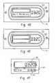
- FIGS. 4A-Gdepict a virtual battery charger.
- FIG. 5depicts a battery charging method.
- a battery charging system 100includes a computer 102 and a battery charger 104 .
- the computer 102also includes one or more general purpose communication interfaces 106 such as a USB port.
- USB portsinclude positive and negative power lines Vbus, GND which in the case of a powered port supply power to a connected device or devices, and data lines D+, D ⁇ .
- the power linesprovide a nominal 5 volts direct current (VDC) supply voltage.
- VDCdirect current
- the supply currentis initially limited to 100 milliamperes (mA). Through a process known as enumeration, a connected device can request additional current in 100 mA increments up to a maximum of 500 mA.
- the computer 102also includes a user interface 108 such as a monitor or display 110 and one or more input devices 112 such as a keyboard and/or mouse which allow the user to interact with the computer 102 through a graphical user interface (GUI), and/or an audible indicator such as a beeper or speaker.
- GUIgraphical user interface
- audible indicatorsuch as a beeper or speaker.
- battery charger application software 114resident on a computer readable storage medium associated with or otherwise accessible to the computer 102 .
- the battery charger application software 114operates in conjunction with the user interface 108 and the communications interface 106 to display the status of or otherwise allow the user to interact with the battery charger 104 through a virtual battery charger 116 which is displayed on the monitor 110 .
- the battery charger 104includes a battery receiving region 120 which is configured to selectively receive one or more batteries for charging.
- the battery receiving region 120receives one (1) or two (2) generally cylindrical AAA or AA-size secondary batteries, although the battery receiving region 120 may be configured to receive other numbers, sizes, and types of batteries.
- Battery contacts 124provide the requisite electrical contact with the terminals of the battery or batteries received in the battery receiving region 120 .
- the communications interface 118is not limited to a USB interface and can include other suitable interfaces.
- the communications interface 118can be implemented as a serial type interface, parallel type interface, firewire interface, network interface, and the like.
- the battery charger application software 114provides charger information via non graphical mechanisms.
- the charger application software 114can indicate insertion of a battery by an audio indicator or can indicate completion of charging by sending a text message.
- the physical 104 and virtual 116 chargersmay take any number of forms, again depending on application-specific factors such as the number and size of the batteries to be charged, desired aesthetics, and the like. While mimicking the form factor of the battery charger 104 and the arrangement of its various elements can ordinarily be expected to facilitate the user's interaction with the system 100 , the physical charger 104 and the virtual charger 116 may also take divergent forms. Rather than being presented in a graphical form, the virtual charger 116 may also be presented in a textual, tabular, or other form.
- the virtual charger 116also includes inputs or widgets such as a close button 204 , a minimize button 206 , a hide button 208 , a pull out menu button 210 , and a maximize button (not illustrated) which facilitate the user's interaction with the virtual charger 116 .
- inputs or widgetssuch as a close button 204 , a minimize button 206 , a hide button 208 , a pull out menu button 210 , and a maximize button (not illustrated) which facilitate the user's interaction with the virtual charger 116 .
- the userconnects the physical charger 104 to the computer 102 , for example by plugging it the computer's USB port 106 , a USB port associated with a powered hub, or into a daisy chained device.
- the physical charger 104 and the computer 102undergo an enumeration process through which the physical charger 104 is identified and the various power levels are determined.
- the virtual charger 116displays the charging status. As illustrated in FIG. 4E , for example, the display 202 presents an estimate of the remaining charging time, with the estimate being updated as charging progresses. Animated or other effects may also be presented to indicate that charging is in progress.
- the virtual chargerwhen charging is complete, the virtual charger presents a suitable charge complete indication, for example through a suitable animation or display graphic, an audible indication, or the like. If the user leaves the virtual battery charger 116 open, the charge complete indication continues to be displayed.
- the virtual charger 116is no longer displayed, the tray icon vanishes, and the physical charger turns off as indicated at 328 .
- the exit/eject function 332which can be selected by clicking on the virtual close button 204 , allows the user to exit the applications software 114 . If charging is incomplete (as indicated at 342 ), the user is prompted to confirm his or her decision at 344 . If the answer is in the affirmative, operation proceeds to step 328 .
- the hide function 334which is selected by clicking on the virtual hide button 208 , allows the user to hide the virtual charger 116 . If selected, only a tray icon is displayed as indicated at 346 .
- the minimize function 336which can be selected by clicking on the virtual minimize button 206 , causes a smaller version 420 of the virtual charger 116 to be displayed (as indicated at 347 ; see FIG. 4F ). Rolling or mousing over the smaller version 420 causes a toolbar 422 to open. In the case of an error, the toolbar 422 is automatically displayed to indicate the error condition (e.g., a bad battery). As indicated at 338 , the user may also elect to display the full virtual charger 116 by selecting the virtual maximize button 424 , in which case the full virtual charger 116 is displayed at 349 .
- the secondary functions 330may also be accessed via the virtual pull out menu button 210 . Where selected, a pullout menu 430 is displayed. As illustrated, the user may select functions such as stop 352 , a pull-down options menu 354 , and skins 356 .
- Selecting the stop function 352causes the physical charger 104 to stop charging (as indicated at 358 ), whereupon the user may elect to restart or toggle charging via an appropriate virtual button as indicated at 360 , whereupon charging resumes at 362 .
- Configuring the options menu 354allows the user to configure the virtual charger 116 .
- configuration optionsinclude the operation of the display 202 , for example by selecting whether charging time is displayed as a time or percentage as indicated at 364 , whether the display counts up or down at 366 .
- Other optionsinclude an auto-start function 368 which, if enabled, causes charging to begin automatically when the physical charger 104 is connected to the communication port 106 and an auto-exit function 370 which automatically closes the application software 114 when charging is complete.
- Still other configuration options 372may also be implemented.
- Selecting the skins menu 356allows the user to customize the appearance of the virtual charger 116 , for example by selecting a skin having a desired color and/or pattern as indicated at 374 .
- the physical battery charger 104is connected to the computer 102 or other host device, for example via a USB port.
- the physical battery charger/host device interfaceis initialized at step 104 .
- the connected deviceis identified as a battery charger, and the available power is determined via the USB enumeration process.
- the powermay be initialized to 100 mA and increased in one or more increments up to a maximum 500 mA.
- the virtual battery charger 116is displayed at 506 , and the user interacts with the physical 104 and virtual 116 chargers as desired.
- the usermay insert one or more batteries in the battery receiving region 120 of the physical charger 104 , configure the virtual charger 116 as desired, and initiate charging.
- the application software 114has not yet been installed on the computer 102 or other host device, the user is prompted to install it, again for example via download over the internet or from a disk suitable computer readable memory.
- the batteriesare charged at 508 . Note that charging may be performed concurrently with other interactions between the user and the virtual charger 116 .
- the userremoves the battery or batteries from the physical charger at 512 and installs the batteries in a desired battery powered appliance at step 514 .
- the application software 114may also be carried in a computer memory contained in the physical battery charger 104 .
- the virtual charger 116may be accessed remotely, for example over the computer network 150 via a suitable web or other interface.
Landscapes
- Engineering & Computer Science (AREA)
- Power Engineering (AREA)
- Health & Medical Sciences (AREA)
- General Health & Medical Sciences (AREA)
- Medical Informatics (AREA)
- Charge And Discharge Circuits For Batteries Or The Like (AREA)
- Secondary Cells (AREA)
Abstract
Description
Claims (37)
Priority Applications (2)
| Application Number | Priority Date | Filing Date | Title |
|---|---|---|---|
| US11/563,437US7612527B2 (en) | 2006-11-27 | 2006-11-27 | Communicative and virtual battery chargers and methods |
| PCT/US2007/024133WO2008066721A2 (en) | 2006-11-27 | 2007-11-19 | Communicative battery charger |
Applications Claiming Priority (1)
| Application Number | Priority Date | Filing Date | Title |
|---|---|---|---|
| US11/563,437US7612527B2 (en) | 2006-11-27 | 2006-11-27 | Communicative and virtual battery chargers and methods |
Publications (2)
| Publication Number | Publication Date |
|---|---|
| US20080122402A1 US20080122402A1 (en) | 2008-05-29 |
| US7612527B2true US7612527B2 (en) | 2009-11-03 |
Family
ID=39327436
Family Applications (1)
| Application Number | Title | Priority Date | Filing Date |
|---|---|---|---|
| US11/563,437Active2027-07-18US7612527B2 (en) | 2006-11-27 | 2006-11-27 | Communicative and virtual battery chargers and methods |
Country Status (2)
| Country | Link |
|---|---|
| US (1) | US7612527B2 (en) |
| WO (1) | WO2008066721A2 (en) |
Cited By (16)
| Publication number | Priority date | Publication date | Assignee | Title |
|---|---|---|---|---|
| US20080259017A1 (en)* | 2007-04-18 | 2008-10-23 | Cypress Semiconductor Corp. | Reducing power consumption in a liquid crystal display |
| US20100148723A1 (en)* | 2008-09-02 | 2010-06-17 | Qualcomm Incorporated | Bidirectional wireless power transmission |
| US20100184371A1 (en)* | 2008-09-17 | 2010-07-22 | Qualcomm Incorporated | Transmitters for wireless power transmission |
| US20100190435A1 (en)* | 2008-08-25 | 2010-07-29 | Qualcomm Incorporated | Passive receivers for wireless power transmission |
| US20110037428A1 (en)* | 2009-08-11 | 2011-02-17 | Buffalo Inc. | Connection apparatus |
| US20120229071A1 (en)* | 2011-03-09 | 2012-09-13 | Schuessler James E | Bi-directional wireless charger |
| US8364870B2 (en) | 2010-09-30 | 2013-01-29 | Cypress Semiconductor Corporation | USB port connected to multiple USB compliant devices |
| US8527949B1 (en) | 2001-11-19 | 2013-09-03 | Cypress Semiconductor Corporation | Graphical user interface for dynamically reconfiguring a programmable device |
| US8564252B2 (en) | 2006-11-10 | 2013-10-22 | Cypress Semiconductor Corporation | Boost buffer aid for reference buffer |
| US20140217989A1 (en)* | 2011-09-02 | 2014-08-07 | Nec Corporation | Battery control system, battery controller, battery control method, and recording medium |
| US20150091496A1 (en)* | 2013-10-01 | 2015-04-02 | Blackberry Limited | Bi-directional communication with a device under charge |
| US9122813B2 (en) | 2012-03-06 | 2015-09-01 | Smsc Holdings S.A.R.L. | USB host determination of whether a USB device provides power via a USB coupling |
| US9667240B2 (en) | 2011-12-02 | 2017-05-30 | Cypress Semiconductor Corporation | Systems and methods for starting up analog circuits |
| US9748782B1 (en) | 2015-01-12 | 2017-08-29 | Google Inc. | Power adapter charging modification based on a feedback loop |
| US9948094B1 (en) | 2015-01-07 | 2018-04-17 | Google Llc | Power level switching circuit for a dual port adapter |
| US20210367434A1 (en)* | 2013-12-23 | 2021-11-25 | Samsung Electronics Co., Ltd. | Method and apparatus for charging a battery |
Families Citing this family (9)
| Publication number | Priority date | Publication date | Assignee | Title |
|---|---|---|---|---|
| WO2010022059A1 (en) | 2008-08-18 | 2010-02-25 | Austin Christopher B | Vehicular battery charger, charging system, and method |
| TW201009199A (en)* | 2010-01-14 | 2010-03-01 | Jye Chuang Electronic Co Ltd | Improved structure of electrical energy exchange device |
| JP6150523B2 (en) | 2010-02-05 | 2017-06-21 | デカ・プロダクツ・リミテッド・パートナーシップ | Infusion pump apparatus, method and system |
| US9662438B2 (en)* | 2010-02-05 | 2017-05-30 | Deka Products Limited Partnership | Devices, methods and systems for wireless control of medical devices |
| US11660392B2 (en) | 2010-02-05 | 2023-05-30 | Deka Products Limited Partnership | Devices, methods and systems for wireless control of medical devices |
| US20130264998A1 (en)* | 2012-04-10 | 2013-10-10 | Imation Corp. | Smart charger for personal media devices |
| CN104253458B (en)* | 2013-06-28 | 2018-06-15 | 富泰华工业(深圳)有限公司 | Performance Test System, test method and the electronic device of USB charge cables |
| EP3258737B1 (en)* | 2015-09-24 | 2020-08-05 | Guangdong Oppo Mobile Telecommunications Corp., Ltd. | Mobile terminal, power supply adapter, and upgrading method thereof |
| JP2018033244A (en)* | 2016-08-24 | 2018-03-01 | キヤノン株式会社 | Electronic device and control method thereof |
Citations (10)
| Publication number | Priority date | Publication date | Assignee | Title |
|---|---|---|---|---|
| EP0711015A2 (en) | 1994-11-04 | 1996-05-08 | Hewlett-Packard Company | Method and apparatus for charging a plurality of batteries for an electronic device |
| KR19990077666A (en) | 1998-03-10 | 1999-10-25 | 이데이 노부유끼 | Power supplying adapter, electronic equipment, and signal transmission system |
| US6078871A (en) | 1998-01-15 | 2000-06-20 | Micron Electronics, Inc. | Method of displaying a status condition of a battery |
| US6184652B1 (en) | 2000-03-14 | 2001-02-06 | Wen-Chin Yang | Mobile phone battery charge with USB interface |
| EP1146621A2 (en) | 2000-04-14 | 2001-10-17 | Zip Charge Co., Ltd. | Charging apparatus |
| US6362610B1 (en) | 2001-08-14 | 2002-03-26 | Fu-I Yang | Universal USB power supply unit |
| US6507172B2 (en) | 2001-03-19 | 2003-01-14 | Maxim Integrated Products, Inc. | Universal serial bus powered battery charger |
| US20050046391A1 (en)* | 2003-02-21 | 2005-03-03 | Research In Motion Limited | Circuit and method of operation for an adaptive charge rate power supply |
| US20050174094A1 (en) | 2004-02-11 | 2005-08-11 | Research In Motion Limited, A Canadian Corporation | Battery charger for portable devices and related methods |
| US20060098460A1 (en) | 2000-03-02 | 2006-05-11 | Balu Balakrishnan | Switched mode power supply responsive to current derived from voltage across energy transfer element input |
- 2006
- 2006-11-27USUS11/563,437patent/US7612527B2/enactiveActive
- 2007
- 2007-11-19WOPCT/US2007/024133patent/WO2008066721A2/enactiveApplication Filing
Patent Citations (11)
| Publication number | Priority date | Publication date | Assignee | Title |
|---|---|---|---|---|
| EP0711015A2 (en) | 1994-11-04 | 1996-05-08 | Hewlett-Packard Company | Method and apparatus for charging a plurality of batteries for an electronic device |
| US6078871A (en) | 1998-01-15 | 2000-06-20 | Micron Electronics, Inc. | Method of displaying a status condition of a battery |
| KR19990077666A (en) | 1998-03-10 | 1999-10-25 | 이데이 노부유끼 | Power supplying adapter, electronic equipment, and signal transmission system |
| US20060098460A1 (en) | 2000-03-02 | 2006-05-11 | Balu Balakrishnan | Switched mode power supply responsive to current derived from voltage across energy transfer element input |
| US7193865B2 (en) | 2000-03-02 | 2007-03-20 | Power Integrations, Inc. | Switched mode power supply responsive to current derived from voltage across energy transfer element input |
| US6184652B1 (en) | 2000-03-14 | 2001-02-06 | Wen-Chin Yang | Mobile phone battery charge with USB interface |
| EP1146621A2 (en) | 2000-04-14 | 2001-10-17 | Zip Charge Co., Ltd. | Charging apparatus |
| US6507172B2 (en) | 2001-03-19 | 2003-01-14 | Maxim Integrated Products, Inc. | Universal serial bus powered battery charger |
| US6362610B1 (en) | 2001-08-14 | 2002-03-26 | Fu-I Yang | Universal USB power supply unit |
| US20050046391A1 (en)* | 2003-02-21 | 2005-03-03 | Research In Motion Limited | Circuit and method of operation for an adaptive charge rate power supply |
| US20050174094A1 (en) | 2004-02-11 | 2005-08-11 | Research In Motion Limited, A Canadian Corporation | Battery charger for portable devices and related methods |
Non-Patent Citations (29)
| Title |
|---|
| Alan Meier, Final Report Research Recommendations to Achieve Energy Savings for Electronic Equipment Operating in Lower Power Modes, Sep. 30, 2002, pp. cover sheet-10. |
| Anderson, Will. How Much Electricity Do You Waste at Home? A New Meter Reveals The, The (London) Independent, Jun. 21, 2006, 3 sheets. |
| California Energy Commission, California Standards for External Power Supplies, Mar. 3, 2005, 4 sheets. |
| Calwell, et al. Power Supplies: A Hidden Opportunity for Energy Savings, NRDC Report, May 22, 2002, pp. cover page-22. |
| Chapman, Matt. Carphone Warehouse leads to green charge, Absolute Gadget, Sep. 4, 2007, 1 sheet, http://www.absolutegadget.com/index2.php?option=com-content&task=view&id=753&pop.... |
| Dallas Semiconductors Maxim, Charging Batteries Using USB Power, Application Note 3241, May 25, 2004, 7 pages, http://www.maxim-ic.com/an3241. |
| David Morison, Battery-Charger ICs are Tailored for Latest Applications, Power Electronics Technology, May 2005, pp. 54-55, www.powerelectronics.com. |
| Energy Star, Energy Star Program Requirements for Products with Battery Charging Systems (BCSs) Draft 2, Eligibility Criteria, downloaded Jul. 24, 2007. pp. 1-9. |
| Energy Star, Energy Star Program Requirements for Single Voltage External Ac-Dc and Ac-Ac Power Supplies Eligibility Criteria, downloaded Jul. 26, 2007, pp. 1-6, version 1.1. |
| Energy Star, Test Methodology for Determining the Energy Performance of Battery Charging System, Oct. 2005, pp. 1-5. |
| Fanara, Andrew. Letter from the United States Environmental Protection Agency Office of Air and Radiation, Oct. 17, 2005, 2 sheets. |
| Friedman, David. Declaring Oil Independence, reprinted from Oct./Nov. 2005 issue of Mother Earth News, Oct. 5, 2005, 2 sheets. |
| Instructables Step-by Step Collaboration, Intro MintyBoost!-Small battery-powered USB charger, downloaded on or before Jun. 15, 2006, 33 pages, http://www.instructables.com/ex/i/1686FF3E41011029AC23001143E7E506/?ALLSTEPS.... |
| Len Sherman, Charge Your Battery Faster By Using a USB Port, Power Electronics Technology, Jan. 2004, pp. 34-40, www.powerelectronics.com. |
| Maxim Integrated Products, Dual -Input, USB/AC adapter, 1-Cell Li+ Charger with OVP and Thermal Regulation, MAX1874, Jul. 2003, p. 1-16, Rev. 0, USA. |
| Maxim Integrated Products, SOT23 Dual-Input USB/AC Adapter 1-Cell Li+ Battery Charges, MAX1551/MAX1555, Jul. 2003, pp. 1-7, Rev. 0, USA. |
| Nokia, Nokia becomes the first phone maker to add energy saving alerts to mobiles, Nokia press release, May 10, 2007, 1 sheet, www.nokia.com. |
| Patent Cooperation Treaty (PCT), International Search Report and Written Opinion for Application No. PCT/US2007/024133, filed Nov. 19, 2007, mailed Aug. 20, 2008, European Patent Office, Netherlands. |
| Patent Cooperation Treaty (PCT), International Search Report and Written Opinion for Application No. PCT/US2008/009797, Filed Aug. 15, 2008, Mailed Mar. 3, 2009, Korean Patent Office, Republic of Korea. |
| Philips Semiconductors, USB On-The-Go: A Tutorial, White Paper, Jan. 2002, 9 sheets. |
| Power Integeration, TNY 263-268 TinySwitch-II Family Enhanced, Energy Efficient Low Power Off-line switcher, data sheet, Apr. 2005, pp. 1-24. |
| Power Integrations, Recent Technology Enhancements in Reducing Standby Power, presentation, Nov. 2006, slides 1-21, www.powerint.com. |
| Power Integrations, TOP242-250 TOPSwitch-GX Family Extended Power, Design Flexible EcoSmart, Integrated Off-line Switcher, data sheet, Nov. 2005, pp. 1-52. |
| Sanders, Robert. Eliminating "standby" electricity loss from home appliances could save up to 25 percent on electrical bills, study shows, University of California Berkeley press release, Feb. 9, 2001, 3 sheets, http://www.berkeley.edu/news/media/releases/2001/02/09-energ.html. |
| Texas Instruments, Single-Chip Charger and DC/DC Converter IC for Bluetooth Headsets and Other Portable Application (bq2501x), SLUS615A-Dec. 2004-Revised Mar. 2005, 24 pages, www.ti.com. |
| Think Geek, George Foreman USB iGrill main description, downloaded on or before Nov. 27, 2006, 2 pages, http://www.thinkgeek.com/stuff/looflirpa/igrill.shtml. |
| THNK Geek, Fundue-desktop USB Fondue set main description, downloaded on or before Nov. 12, 2006, 3 pages, http://www.thinkgeek.com/stuff/41/fundue.shtml. |
| USB-IF, Battery Charging Specification, Mar. 8, 2007, pp. cover page-25, rev. 1.0. |
| Wikipedia, The Free Encyclopedia, Universal Serial Bus, page last modified Nov. 10, 2006, 28 pages, http://en.wikipedia.org/wiki/usb-connection. |
Cited By (38)
| Publication number | Priority date | Publication date | Assignee | Title |
|---|---|---|---|---|
| US8527949B1 (en) | 2001-11-19 | 2013-09-03 | Cypress Semiconductor Corporation | Graphical user interface for dynamically reconfiguring a programmable device |
| US8533677B1 (en) | 2001-11-19 | 2013-09-10 | Cypress Semiconductor Corporation | Graphical user interface for dynamically reconfiguring a programmable device |
| US8564252B2 (en) | 2006-11-10 | 2013-10-22 | Cypress Semiconductor Corporation | Boost buffer aid for reference buffer |
| US9407257B2 (en) | 2007-04-18 | 2016-08-02 | Cypress Semiconductor Corporation | Reducing power consumption in a liquid crystal display |
| US20080259070A1 (en)* | 2007-04-18 | 2008-10-23 | Cypress Semiconductor Corporation | Active liquid crystal display drivers and duty cycle operation |
| US9124264B2 (en) | 2007-04-18 | 2015-09-01 | Cypress Semiconductor Corporation | Load driver |
| US11876510B2 (en) | 2007-04-18 | 2024-01-16 | Monterey Research, Llc | Load driver |
| US20120166700A1 (en)* | 2007-04-18 | 2012-06-28 | Cypress Semiconductor Corporation | Specialized universal serial bus controller |
| US11223352B2 (en) | 2007-04-18 | 2022-01-11 | Monterey Research, Llc | Load driver |
| US10418990B2 (en) | 2007-04-18 | 2019-09-17 | Monterey Research, Llc | Load driver |
| US8686985B2 (en) | 2007-04-18 | 2014-04-01 | Cypress Semiconductor Corporation | Active liquid crystal display drivers and duty cycle operation |
| US8661168B2 (en)* | 2007-04-18 | 2014-02-25 | Cypress Semiconductor Corporation | Specialized universal serial bus controller |
| US8902131B2 (en) | 2007-04-18 | 2014-12-02 | Cypress Semiconductor Corporation | Configurable liquid crystal display driver system |
| US9923559B2 (en) | 2007-04-18 | 2018-03-20 | Monterey Research, Llc | Load driver |
| US20080259065A1 (en)* | 2007-04-18 | 2008-10-23 | Cypress Semiconductor Corporation | Configurable liquid crystal display driver system |
| US8570073B2 (en) | 2007-04-18 | 2013-10-29 | Cypress Semiconductor Corporation | Load driver |
| US20080259017A1 (en)* | 2007-04-18 | 2008-10-23 | Cypress Semiconductor Corp. | Reducing power consumption in a liquid crystal display |
| US8432070B2 (en) | 2008-08-25 | 2013-04-30 | Qualcomm Incorporated | Passive receivers for wireless power transmission |
| US20100190435A1 (en)* | 2008-08-25 | 2010-07-29 | Qualcomm Incorporated | Passive receivers for wireless power transmission |
| US20100148723A1 (en)* | 2008-09-02 | 2010-06-17 | Qualcomm Incorporated | Bidirectional wireless power transmission |
| US8947041B2 (en)* | 2008-09-02 | 2015-02-03 | Qualcomm Incorporated | Bidirectional wireless power transmission |
| US9425653B2 (en) | 2008-09-17 | 2016-08-23 | Qualcomm Incorporated | Transmitters for wireless power transmission |
| US20100184371A1 (en)* | 2008-09-17 | 2010-07-22 | Qualcomm Incorporated | Transmitters for wireless power transmission |
| US8532724B2 (en) | 2008-09-17 | 2013-09-10 | Qualcomm Incorporated | Transmitters for wireless power transmission |
| US20110037428A1 (en)* | 2009-08-11 | 2011-02-17 | Buffalo Inc. | Connection apparatus |
| US8364870B2 (en) | 2010-09-30 | 2013-01-29 | Cypress Semiconductor Corporation | USB port connected to multiple USB compliant devices |
| US8645598B2 (en) | 2010-09-30 | 2014-02-04 | Cypress Semiconductor Corp. | Downstream interface ports for connecting to USB capable devices |
| US9444284B2 (en)* | 2011-03-09 | 2016-09-13 | National Semiconductor Corporation | Bi-directional wireless charger |
| US8901875B2 (en)* | 2011-03-09 | 2014-12-02 | National Semiconductor Corporation | Bi-directional wireless charger |
| US20120229071A1 (en)* | 2011-03-09 | 2012-09-13 | Schuessler James E | Bi-directional wireless charger |
| US20150084577A1 (en)* | 2011-03-09 | 2015-03-26 | National Semiconductor Corporation | Bi-directional wireless charger |
| US20140217989A1 (en)* | 2011-09-02 | 2014-08-07 | Nec Corporation | Battery control system, battery controller, battery control method, and recording medium |
| US9667240B2 (en) | 2011-12-02 | 2017-05-30 | Cypress Semiconductor Corporation | Systems and methods for starting up analog circuits |
| US9122813B2 (en) | 2012-03-06 | 2015-09-01 | Smsc Holdings S.A.R.L. | USB host determination of whether a USB device provides power via a USB coupling |
| US20150091496A1 (en)* | 2013-10-01 | 2015-04-02 | Blackberry Limited | Bi-directional communication with a device under charge |
| US20210367434A1 (en)* | 2013-12-23 | 2021-11-25 | Samsung Electronics Co., Ltd. | Method and apparatus for charging a battery |
| US9948094B1 (en) | 2015-01-07 | 2018-04-17 | Google Llc | Power level switching circuit for a dual port adapter |
| US9748782B1 (en) | 2015-01-12 | 2017-08-29 | Google Inc. | Power adapter charging modification based on a feedback loop |
Also Published As
| Publication number | Publication date |
|---|---|
| WO2008066721A3 (en) | 2008-10-09 |
| WO2008066721A2 (en) | 2008-06-05 |
| US20080122402A1 (en) | 2008-05-29 |
| WO2008066721B1 (en) | 2008-12-24 |
Similar Documents
| Publication | Publication Date | Title |
|---|---|---|
| US7612527B2 (en) | Communicative and virtual battery chargers and methods | |
| EP2774017B1 (en) | Device charging over usb using a plurality of handshakes | |
| US9094949B2 (en) | Multi-host wireless input device | |
| KR102231741B1 (en) | Accessory device power management | |
| US8332545B1 (en) | USB switch which allows primary USB connection in response to USB signaling | |
| EP2069880B1 (en) | Method and device for activating functions of a powered-off device via a serial data bus interface | |
| US20100162011A1 (en) | Method and apparatus for controlling interrupts in portable terminal | |
| EP2051493A1 (en) | Mobile terminal aware of externally connected device and control method for the same | |
| EP3348314A1 (en) | Operation system, game system, and game controller capable of identifying connected device with simplified scheme | |
| KR20150016859A (en) | protecting case | |
| CN105322615A (en) | Charging control method and electronic device for supporting the same | |
| KR20110129202A (en) | Computer system and its control method | |
| EP1830839A2 (en) | System and method for power management in mobile units | |
| US10923910B2 (en) | Systems and methods for accepting variable input power from an external power source | |
| CN109783424B (en) | Electronic device capable of customizing USB connection mode and control method thereof | |
| CN103257675B (en) | The control method of terminal device and its dual graphic processing unit | |
| CN202956930U (en) | Wireless document demonstration remote controller | |
| JP2010029059A (en) | Battery management system, and battery management method | |
| CN112117811A (en) | Intelligent power adapter and power transmission management method thereof | |
| WO2016024238A2 (en) | Charging device for computing appliances | |
| CN117850565B (en) | Power supply device, firmware upgrade method, and readable storage medium | |
| CN109768594B (en) | Charging method, terminal and charging component |
Legal Events
| Date | Code | Title | Description |
|---|---|---|---|
| AS | Assignment | Owner name:CHASE DESIGN, INC., NEW YORK Free format text:ASSIGNMENT OF ASSIGNORS INTEREST;ASSIGNORS:OSIECKI, SCOTT W.;CASTELLUCCI, PETER C.;REEL/FRAME:018674/0456 Effective date:20061219 Owner name:EVEREADY BATTERY COMPANY, INC., MISSOURI Free format text:ASSIGNMENT OF ASSIGNORS INTEREST;ASSIGNORS:HOFFMAN, PETER F.;BRANDON, MICHAEL J., II;MOFFAT, JENNIFER ANA;REEL/FRAME:018678/0743;SIGNING DATES FROM 20061214 TO 20061218 Owner name:EVEREADY BATTERY COMPANY, INC., MISSOURI Free format text:ASSIGNMENT OF ASSIGNORS INTEREST;ASSIGNOR:CHASE DESIGN, INC.;REEL/FRAME:018674/0488 Effective date:20061219 | |
| AS | Assignment | Owner name:EVEREADY BATTERY COMPANY, INC., MISSOURI Free format text:ASSIGNMENT OF ASSIGNORS INTEREST;ASSIGNORS:HOFFMAN, PETER F.;BRANDON, MICHAEL J. II;MOFFAT, JENNIFER ANA;REEL/FRAME:018696/0016;SIGNING DATES FROM 20061214 TO 20061218 | |
| STCF | Information on status: patent grant | Free format text:PATENTED CASE | |
| FPAY | Fee payment | Year of fee payment:4 | |
| AS | Assignment | Owner name:ENERGIZER BRANDS, LLC, MISSOURI Free format text:ASSIGNMENT OF ASSIGNORS INTEREST;ASSIGNOR:EVEREADY BATTERY COMPANY, INC.;REEL/FRAME:036019/0814 Effective date:20150601 | |
| AS | Assignment | Owner name:JPMORGAN CHASE BANK, N.A., AS AGENT, ILLINOIS Free format text:SECURITY AGREEMENT;ASSIGNOR:ENERGIZER BRANDS, LLC;REEL/FRAME:036106/0392 Effective date:20150630 | |
| AS | Assignment | Owner name:ENERGIZER BRANDS, LLC, MISSOURI Free format text:CORRECTIVE ASSIGNMENT TO CORRECT THE APPLICATION NUMBER 29/499,135 PREVIOUSLY RECORDED AT REEL: 036019 FRAME: 814. ASSIGNOR(S) HEREBY CONFIRMS THE ASSIGNMENT;ASSIGNOR:EVEREADY BATTERY COMPANY;REEL/FRAME:040054/0660 Effective date:20160601 | |
| FPAY | Fee payment | Year of fee payment:8 | |
| AS | Assignment | Owner name:ENERGIZER BRANDS, LLC, MISSOURI Free format text:TERMINATION AND RELEASE OF SECURITY INTEREST IN PATENT RIGHTS;ASSIGNOR:JPMORGAN CHASE BANK, N.A., AS ADMINISTRATIVE AGENT;REEL/FRAME:048888/0300 Effective date:20190102 Owner name:JPMORGAN CHASE BANK, N.A., AS ADMINISTRATIVE AGENT, ILLINOIS Free format text:PATENT SECURITY AGREEMENT;ASSIGNORS:ENERGIZER HOLDINGS, INC.;AMERICAN COVERS, LLC;ASSOCIATED PRODUCTS, LLC;AND OTHERS;REEL/FRAME:048029/0246 Effective date:20190102 Owner name:JPMORGAN CHASE BANK, N.A., AS ADMINISTRATIVE AGENT Free format text:PATENT SECURITY AGREEMENT;ASSIGNORS:ENERGIZER HOLDINGS, INC.;AMERICAN COVERS, LLC;ASSOCIATED PRODUCTS, LLC;AND OTHERS;REEL/FRAME:048029/0246 Effective date:20190102 | |
| AS | Assignment | Owner name:JPMORGAN CHASE BANK, N.A., AS ADMINISTRATIVE AGENT, ILLINOIS Free format text:PATENT SECURITY AGREEMENT;ASSIGNORS:ENERGIZER BRANDS, LLC;ENERGIZER AUTO, INC.;REEL/FRAME:054875/0651 Effective date:20201222 Owner name:JPMORGAN CHASE BANK, N.A., AS ADMINISTRATIVE AGENT, ILLINOIS Free format text:PATENT SECURITY AGREEMENT;ASSIGNORS:ENERGIZER BRANDS, LLC;ENERGIZER AUTO, INC.;REEL/FRAME:054875/0504 Effective date:20201222 | |
| MAFP | Maintenance fee payment | Free format text:PAYMENT OF MAINTENANCE FEE, 12TH YEAR, LARGE ENTITY (ORIGINAL EVENT CODE: M1553); ENTITY STATUS OF PATENT OWNER: LARGE ENTITY Year of fee payment:12 | |
| AS | Assignment | Owner name:JPMORGAN CHASE BANK, N.A., AS COLLATERAL AGENT, ILLINOIS Free format text:AMENDED AND RESTATED INTELLECTUAL PROPERTY SECURITY AGREEMENT;ASSIGNORS:ENERGIZER BRANDS, LLC;ENERGIZER AUTO, INC.,;ENERGIZER AUTO SALES, INC.;REEL/FRAME:070565/0282 Effective date:20250319 |