US7612466B2 - System and method for coordinated control and utilization of local storage and generation, with a power grid - Google Patents
System and method for coordinated control and utilization of local storage and generation, with a power gridDownload PDFInfo
- Publication number
- US7612466B2 US7612466B2US12/021,185US2118508AUS7612466B2US 7612466 B2US7612466 B2US 7612466B2US 2118508 AUS2118508 AUS 2118508AUS 7612466 B2US7612466 B2US 7612466B2
- Authority
- US
- United States
- Prior art keywords
- recited
- power
- interfaces
- energy storage
- phase
- Prior art date
- Legal status (The legal status is an assumption and is not a legal conclusion. Google has not performed a legal analysis and makes no representation as to the accuracy of the status listed.)
- Active - Reinstated, expires
Links
- 238000003860storageMethods0.000titleclaimsabstractdescription9
- 238000000034methodMethods0.000titleabstractdescription17
- 238000004146energy storageMethods0.000claimsabstractdescription29
- 238000012546transferMethods0.000claimsabstractdescription4
- 238000005457optimizationMethods0.000claimsabstractdescription3
- 230000002452interceptive effectEffects0.000claimsdescription16
- 238000009826distributionMethods0.000claimsdescription11
- 230000002457bidirectional effectEffects0.000claimsdescription5
- 238000013528artificial neural networkMethods0.000claimsdescription3
- 239000000126substanceSubstances0.000claimsdescription2
- 230000010354integrationEffects0.000abstractdescription3
- 230000008569processEffects0.000description4
- 238000006243chemical reactionMethods0.000description3
- 239000011159matrix materialSubstances0.000description3
- 238000012358sourcingMethods0.000description3
- 238000004364calculation methodMethods0.000description2
- 230000008859changeEffects0.000description2
- 238000011157data evaluationMethods0.000description2
- 238000005516engineering processMethods0.000description2
- 238000011156evaluationMethods0.000description2
- 241000321453Paranthias colonusSpecies0.000description1
- 238000004422calculation algorithmMethods0.000description1
- 239000003245coalSubstances0.000description1
- 238000004590computer programMethods0.000description1
- 238000010586diagramMethods0.000description1
- 230000002708enhancing effectEffects0.000description1
- 230000007613environmental effectEffects0.000description1
- 238000009434installationMethods0.000description1
- 238000007726management methodMethods0.000description1
- 238000004519manufacturing processMethods0.000description1
- 230000007246mechanismEffects0.000description1
- 238000012806monitoring deviceMethods0.000description1
- 238000012544monitoring processMethods0.000description1
- 239000002245particleSubstances0.000description1
- 238000005057refrigerationMethods0.000description1
- 230000004044responseEffects0.000description1
- 238000005070samplingMethods0.000description1
- 229920006395saturated elastomerPolymers0.000description1
- 238000009827uniform distributionMethods0.000description1
Images


Classifications
- B—PERFORMING OPERATIONS; TRANSPORTING
- B60—VEHICLES IN GENERAL
- B60L—PROPULSION OF ELECTRICALLY-PROPELLED VEHICLES; SUPPLYING ELECTRIC POWER FOR AUXILIARY EQUIPMENT OF ELECTRICALLY-PROPELLED VEHICLES; ELECTRODYNAMIC BRAKE SYSTEMS FOR VEHICLES IN GENERAL; MAGNETIC SUSPENSION OR LEVITATION FOR VEHICLES; MONITORING OPERATING VARIABLES OF ELECTRICALLY-PROPELLED VEHICLES; ELECTRIC SAFETY DEVICES FOR ELECTRICALLY-PROPELLED VEHICLES
- B60L55/00—Arrangements for supplying energy stored within a vehicle to a power network, i.e. vehicle-to-grid [V2G] arrangements
- H—ELECTRICITY
- H02—GENERATION; CONVERSION OR DISTRIBUTION OF ELECTRIC POWER
- H02J—CIRCUIT ARRANGEMENTS OR SYSTEMS FOR SUPPLYING OR DISTRIBUTING ELECTRIC POWER; SYSTEMS FOR STORING ELECTRIC ENERGY
- H02J3/00—Circuit arrangements for AC mains or AC distribution networks
- H02J3/26—Arrangements for eliminating or reducing asymmetry in polyphase networks
- H—ELECTRICITY
- H02—GENERATION; CONVERSION OR DISTRIBUTION OF ELECTRIC POWER
- H02J—CIRCUIT ARRANGEMENTS OR SYSTEMS FOR SUPPLYING OR DISTRIBUTING ELECTRIC POWER; SYSTEMS FOR STORING ELECTRIC ENERGY
- H02J3/00—Circuit arrangements for AC mains or AC distribution networks
- H02J3/28—Arrangements for balancing of the load in a network by storage of energy
- H—ELECTRICITY
- H02—GENERATION; CONVERSION OR DISTRIBUTION OF ELECTRIC POWER
- H02J—CIRCUIT ARRANGEMENTS OR SYSTEMS FOR SUPPLYING OR DISTRIBUTING ELECTRIC POWER; SYSTEMS FOR STORING ELECTRIC ENERGY
- H02J3/00—Circuit arrangements for AC mains or AC distribution networks
- H02J3/38—Arrangements for parallely feeding a single network by two or more generators, converters or transformers
- H02J3/381—Dispersed generators
- H—ELECTRICITY
- H02—GENERATION; CONVERSION OR DISTRIBUTION OF ELECTRIC POWER
- H02J—CIRCUIT ARRANGEMENTS OR SYSTEMS FOR SUPPLYING OR DISTRIBUTING ELECTRIC POWER; SYSTEMS FOR STORING ELECTRIC ENERGY
- H02J3/00—Circuit arrangements for AC mains or AC distribution networks
- H02J3/38—Arrangements for parallely feeding a single network by two or more generators, converters or transformers
- H02J3/46—Controlling of the sharing of output between the generators, converters, or transformers
- H—ELECTRICITY
- H02—GENERATION; CONVERSION OR DISTRIBUTION OF ELECTRIC POWER
- H02J—CIRCUIT ARRANGEMENTS OR SYSTEMS FOR SUPPLYING OR DISTRIBUTING ELECTRIC POWER; SYSTEMS FOR STORING ELECTRIC ENERGY
- H02J2300/00—Systems for supplying or distributing electric power characterised by decentralized, dispersed, or local generation
- H02J2300/20—The dispersed energy generation being of renewable origin
- H02J2300/22—The renewable source being solar energy
- H02J2300/24—The renewable source being solar energy of photovoltaic origin
- H—ELECTRICITY
- H02—GENERATION; CONVERSION OR DISTRIBUTION OF ELECTRIC POWER
- H02J—CIRCUIT ARRANGEMENTS OR SYSTEMS FOR SUPPLYING OR DISTRIBUTING ELECTRIC POWER; SYSTEMS FOR STORING ELECTRIC ENERGY
- H02J2300/00—Systems for supplying or distributing electric power characterised by decentralized, dispersed, or local generation
- H02J2300/20—The dispersed energy generation being of renewable origin
- H02J2300/28—The renewable source being wind energy
- H—ELECTRICITY
- H02—GENERATION; CONVERSION OR DISTRIBUTION OF ELECTRIC POWER
- H02J—CIRCUIT ARRANGEMENTS OR SYSTEMS FOR SUPPLYING OR DISTRIBUTING ELECTRIC POWER; SYSTEMS FOR STORING ELECTRIC ENERGY
- H02J2300/00—Systems for supplying or distributing electric power characterised by decentralized, dispersed, or local generation
- H02J2300/40—Systems for supplying or distributing electric power characterised by decentralized, dispersed, or local generation wherein a plurality of decentralised, dispersed or local energy generation technologies are operated simultaneously
- Y—GENERAL TAGGING OF NEW TECHNOLOGICAL DEVELOPMENTS; GENERAL TAGGING OF CROSS-SECTIONAL TECHNOLOGIES SPANNING OVER SEVERAL SECTIONS OF THE IPC; TECHNICAL SUBJECTS COVERED BY FORMER USPC CROSS-REFERENCE ART COLLECTIONS [XRACs] AND DIGESTS
- Y02—TECHNOLOGIES OR APPLICATIONS FOR MITIGATION OR ADAPTATION AGAINST CLIMATE CHANGE
- Y02E—REDUCTION OF GREENHOUSE GAS [GHG] EMISSIONS, RELATED TO ENERGY GENERATION, TRANSMISSION OR DISTRIBUTION
- Y02E10/00—Energy generation through renewable energy sources
- Y02E10/50—Photovoltaic [PV] energy
- Y02E10/56—Power conversion systems, e.g. maximum power point trackers
- Y—GENERAL TAGGING OF NEW TECHNOLOGICAL DEVELOPMENTS; GENERAL TAGGING OF CROSS-SECTIONAL TECHNOLOGIES SPANNING OVER SEVERAL SECTIONS OF THE IPC; TECHNICAL SUBJECTS COVERED BY FORMER USPC CROSS-REFERENCE ART COLLECTIONS [XRACs] AND DIGESTS
- Y02—TECHNOLOGIES OR APPLICATIONS FOR MITIGATION OR ADAPTATION AGAINST CLIMATE CHANGE
- Y02E—REDUCTION OF GREENHOUSE GAS [GHG] EMISSIONS, RELATED TO ENERGY GENERATION, TRANSMISSION OR DISTRIBUTION
- Y02E10/00—Energy generation through renewable energy sources
- Y02E10/70—Wind energy
- Y02E10/76—Power conversion electric or electronic aspects
- Y—GENERAL TAGGING OF NEW TECHNOLOGICAL DEVELOPMENTS; GENERAL TAGGING OF CROSS-SECTIONAL TECHNOLOGIES SPANNING OVER SEVERAL SECTIONS OF THE IPC; TECHNICAL SUBJECTS COVERED BY FORMER USPC CROSS-REFERENCE ART COLLECTIONS [XRACs] AND DIGESTS
- Y02—TECHNOLOGIES OR APPLICATIONS FOR MITIGATION OR ADAPTATION AGAINST CLIMATE CHANGE
- Y02E—REDUCTION OF GREENHOUSE GAS [GHG] EMISSIONS, RELATED TO ENERGY GENERATION, TRANSMISSION OR DISTRIBUTION
- Y02E40/00—Technologies for an efficient electrical power generation, transmission or distribution
- Y02E40/50—Arrangements for eliminating or reducing asymmetry in polyphase networks
- Y—GENERAL TAGGING OF NEW TECHNOLOGICAL DEVELOPMENTS; GENERAL TAGGING OF CROSS-SECTIONAL TECHNOLOGIES SPANNING OVER SEVERAL SECTIONS OF THE IPC; TECHNICAL SUBJECTS COVERED BY FORMER USPC CROSS-REFERENCE ART COLLECTIONS [XRACs] AND DIGESTS
- Y02—TECHNOLOGIES OR APPLICATIONS FOR MITIGATION OR ADAPTATION AGAINST CLIMATE CHANGE
- Y02E—REDUCTION OF GREENHOUSE GAS [GHG] EMISSIONS, RELATED TO ENERGY GENERATION, TRANSMISSION OR DISTRIBUTION
- Y02E60/00—Enabling technologies; Technologies with a potential or indirect contribution to GHG emissions mitigation
- Y—GENERAL TAGGING OF NEW TECHNOLOGICAL DEVELOPMENTS; GENERAL TAGGING OF CROSS-SECTIONAL TECHNOLOGIES SPANNING OVER SEVERAL SECTIONS OF THE IPC; TECHNICAL SUBJECTS COVERED BY FORMER USPC CROSS-REFERENCE ART COLLECTIONS [XRACs] AND DIGESTS
- Y02—TECHNOLOGIES OR APPLICATIONS FOR MITIGATION OR ADAPTATION AGAINST CLIMATE CHANGE
- Y02E—REDUCTION OF GREENHOUSE GAS [GHG] EMISSIONS, RELATED TO ENERGY GENERATION, TRANSMISSION OR DISTRIBUTION
- Y02E70/00—Other energy conversion or management systems reducing GHG emissions
- Y02E70/30—Systems combining energy storage with energy generation of non-fossil origin
- Y—GENERAL TAGGING OF NEW TECHNOLOGICAL DEVELOPMENTS; GENERAL TAGGING OF CROSS-SECTIONAL TECHNOLOGIES SPANNING OVER SEVERAL SECTIONS OF THE IPC; TECHNICAL SUBJECTS COVERED BY FORMER USPC CROSS-REFERENCE ART COLLECTIONS [XRACs] AND DIGESTS
- Y02—TECHNOLOGIES OR APPLICATIONS FOR MITIGATION OR ADAPTATION AGAINST CLIMATE CHANGE
- Y02T—CLIMATE CHANGE MITIGATION TECHNOLOGIES RELATED TO TRANSPORTATION
- Y02T10/00—Road transport of goods or passengers
- Y02T10/60—Other road transportation technologies with climate change mitigation effect
- Y02T10/70—Energy storage systems for electromobility, e.g. batteries
- Y—GENERAL TAGGING OF NEW TECHNOLOGICAL DEVELOPMENTS; GENERAL TAGGING OF CROSS-SECTIONAL TECHNOLOGIES SPANNING OVER SEVERAL SECTIONS OF THE IPC; TECHNICAL SUBJECTS COVERED BY FORMER USPC CROSS-REFERENCE ART COLLECTIONS [XRACs] AND DIGESTS
- Y02—TECHNOLOGIES OR APPLICATIONS FOR MITIGATION OR ADAPTATION AGAINST CLIMATE CHANGE
- Y02T—CLIMATE CHANGE MITIGATION TECHNOLOGIES RELATED TO TRANSPORTATION
- Y02T10/00—Road transport of goods or passengers
- Y02T10/60—Other road transportation technologies with climate change mitigation effect
- Y02T10/7072—Electromobility specific charging systems or methods for batteries, ultracapacitors, supercapacitors or double-layer capacitors
- Y—GENERAL TAGGING OF NEW TECHNOLOGICAL DEVELOPMENTS; GENERAL TAGGING OF CROSS-SECTIONAL TECHNOLOGIES SPANNING OVER SEVERAL SECTIONS OF THE IPC; TECHNICAL SUBJECTS COVERED BY FORMER USPC CROSS-REFERENCE ART COLLECTIONS [XRACs] AND DIGESTS
- Y02—TECHNOLOGIES OR APPLICATIONS FOR MITIGATION OR ADAPTATION AGAINST CLIMATE CHANGE
- Y02T—CLIMATE CHANGE MITIGATION TECHNOLOGIES RELATED TO TRANSPORTATION
- Y02T90/00—Enabling technologies or technologies with a potential or indirect contribution to GHG emissions mitigation
- Y02T90/10—Technologies relating to charging of electric vehicles
- Y02T90/12—Electric charging stations
- Y—GENERAL TAGGING OF NEW TECHNOLOGICAL DEVELOPMENTS; GENERAL TAGGING OF CROSS-SECTIONAL TECHNOLOGIES SPANNING OVER SEVERAL SECTIONS OF THE IPC; TECHNICAL SUBJECTS COVERED BY FORMER USPC CROSS-REFERENCE ART COLLECTIONS [XRACs] AND DIGESTS
- Y02—TECHNOLOGIES OR APPLICATIONS FOR MITIGATION OR ADAPTATION AGAINST CLIMATE CHANGE
- Y02T—CLIMATE CHANGE MITIGATION TECHNOLOGIES RELATED TO TRANSPORTATION
- Y02T90/00—Enabling technologies or technologies with a potential or indirect contribution to GHG emissions mitigation
- Y02T90/10—Technologies relating to charging of electric vehicles
- Y02T90/14—Plug-in electric vehicles
- Y—GENERAL TAGGING OF NEW TECHNOLOGICAL DEVELOPMENTS; GENERAL TAGGING OF CROSS-SECTIONAL TECHNOLOGIES SPANNING OVER SEVERAL SECTIONS OF THE IPC; TECHNICAL SUBJECTS COVERED BY FORMER USPC CROSS-REFERENCE ART COLLECTIONS [XRACs] AND DIGESTS
- Y02—TECHNOLOGIES OR APPLICATIONS FOR MITIGATION OR ADAPTATION AGAINST CLIMATE CHANGE
- Y02T—CLIMATE CHANGE MITIGATION TECHNOLOGIES RELATED TO TRANSPORTATION
- Y02T90/00—Enabling technologies or technologies with a potential or indirect contribution to GHG emissions mitigation
- Y02T90/10—Technologies relating to charging of electric vehicles
- Y02T90/16—Information or communication technologies improving the operation of electric vehicles
- Y—GENERAL TAGGING OF NEW TECHNOLOGICAL DEVELOPMENTS; GENERAL TAGGING OF CROSS-SECTIONAL TECHNOLOGIES SPANNING OVER SEVERAL SECTIONS OF THE IPC; TECHNICAL SUBJECTS COVERED BY FORMER USPC CROSS-REFERENCE ART COLLECTIONS [XRACs] AND DIGESTS
- Y04—INFORMATION OR COMMUNICATION TECHNOLOGIES HAVING AN IMPACT ON OTHER TECHNOLOGY AREAS
- Y04S—SYSTEMS INTEGRATING TECHNOLOGIES RELATED TO POWER NETWORK OPERATION, COMMUNICATION OR INFORMATION TECHNOLOGIES FOR IMPROVING THE ELECTRICAL POWER GENERATION, TRANSMISSION, DISTRIBUTION, MANAGEMENT OR USAGE, i.e. SMART GRIDS
- Y04S10/00—Systems supporting electrical power generation, transmission or distribution
- Y04S10/12—Monitoring or controlling equipment for energy generation units, e.g. distributed energy generation [DER] or load-side generation
- Y04S10/126—Monitoring or controlling equipment for energy generation units, e.g. distributed energy generation [DER] or load-side generation the energy generation units being or involving electric vehicles [EV] or hybrid vehicles [HEV], i.e. power aggregation of EV or HEV, vehicle to grid arrangements [V2G]
Definitions
- This inventionimproves the efficiency and functionality of a grid-tied power system that utilizes one or more local power sources and one or more local energy storage devices.
- the purpose of the inventionis the coordination, optimization and efficient control, regulation, and transfer of electrical energy among several energy storage devices, power generators, the utility grid, and connected local electrical loads.
- the coordinated control and utilization of local storage and generation combined with coordinated integration with the utility gridresults in an overall system that can be more flexible, economical, and efficient than any of the individual components can be, when operated separately.
- the loads on the individual phases of the systemIn poly-phase power distribution systems, it is desirable to balance the loads on the individual phases of the system. Ideally, the loads on all the phases should be close to equal or balanced. For example, it would be unacceptable for the loads on one phase to greatly exceed the loads on the other phases of a poly-phase system. As used herein, the word “balanced” means that the loads on the individual phases are equal within acceptable limits for the power distribution system in use; however, it does not mean that the loads on each phase are exactly equal or that the loads on all phases are non-zero.
- load-balancingis accomplished by the electrician wiring the system. To do this, the electrician must keep an accounting of the power requirements of all the loads on each phase and add loads to, or remove loads from, each phase as necessary to achieve the desired balance. This method is very tedious and time consuming, during the installation of the system. In addition, for larger number of loads, this is not practical for a person to account for, and becomes very inefficient, inaccurate, and slow.
- U.S. Pat. No. 5,934,096discloses a wiring system for commercial refrigeration which permits power to be balanced among three phases of electrical power, which is an example of a traditional way of load-balancing, in addition to a good explanation of other prior art.
- this systemprovides a method to realize the advantages of various distributed generation and energy storage technologies as parts of a system where they would be inadequate or uneconomical as a stand-alone energy source.
- the controller discussed in this inventiondynamically assigns/balances loads between different phases.
- An example of this systemincludes a combination of solar and wind power generators, as local sources, multiple bidirectional plug-in hybrid electric vehicles (BPHEV) or battery electric vehicles (BEV) that are used as local energy storage/generation devices, local loads, a connection to the electric utility grid, and a central switch transfer unit that acts to configure the interconnection of sources, loads, storage elements and utility grid.
- BPHEVbidirectional plug-in hybrid electric vehicles
- BEVbattery electric vehicles
- FIG. 1describes an embodiment for the structure of the current invention. It describes one embodiment of the multi-sourced, controlled power distribution system.
- the energy storage units external to the facilityrepresent removable devices, such as vehicles with energy storage capability.
- FIG. 2describes an embodiment (flowchart) for the method of the current invention.
- FIG. 3describes an embodiment (controller) for our invention (system).
- FIG. 4describes the details of an embodiment of the controlled switchgear in FIG. 3 .
- FIG. 5is the dynamic adjustment of loads/phases, using a feedback loop, as one embodiment.
- This systembuilds on existing technologies for power conversion, energy storage, grid interconnection, and load switching. It adds control and interconnection flexibility that allows for dynamic system reconfiguration.
- a power hub systemin one embodiment, comprises:
- FIG. 1shows a block diagram of one embodiment of the power hub system.
- the systemis designed to function correctly in several configurations that are highlighted in the figure.
- the DC local sourcesmay connect to a local energy storage unit through a DC/DC converter, directly, or to the multiple removable energy storage modules (vehicles) through the DC/AC inverter and a rectifier/inverter in the vehicle, or other DC storage element.
- Alternate generation sources and energy storage devicesare also possible, including micro-turbine sources, flywheel energy storage systems, etc.
- the power hub controllerconfigures the appropriate power connections to meet the dynamic requirements and/or command objectives.
- the facility shown in FIG. 1can be connected to the utility grid, either through a single-phase interface or through a three-phase interface.
- the removable energy storage units shown in the figureare connected to the facility AC power system either through a single-phase connection and/or through a three-phase connection.
- the removable loads that connect via a single-phase connectionwill be placed in parallel with the loads on a particular system phase.
- FIG. 1includes a dynamic phase assignment block that is capable of connecting energy storage units plugged into a single-phase connection to any of the three power phases.
- the controllermonitors the overall system power flow and determines the optimal configuration on a dynamic basis, as removable energy storage unit connect and disconnect to the system. It also responds to pricing information and ancillary service requests communicated by the utility.
- the different sources of energyare connected to the system, e.g. wind, solar, and micro-turbine.
- FIG. 2shows the flow chart for balanced condition, with respect to load data and connected generation/phases. For each phase A, B, and C, we will have connected generator and load data. Then, it checks to see if it is within tolerance. If so, it starts again the process. Otherwise, it would compute a new configuration for matching load requirements with source capabilities and would set the command controllable devices to desired configurations. Then, after updating switch configuration, it will repeat the process again from the start.
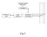
- FIG. 3shows the relationship between the load interface and the controller, as a part of the overall system. Load and system information are supplied to the controller, which feeds the controlled switch gear, which is connected to the load interface, plus interactive load module.
- the controlled switch gearis connected to the power lines: L 1 , L 2 , and L 3 , plus N.
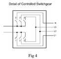
- FIG. 4shows details of one implementation of the controllable switchgear of FIG. 3 .
- the single-phase interactive loadcan be connected across any pair of the four-wire power lines shown: L 1 , L 2 , and L 3 , plus N (common line).
- FIG. 5shows the dynamic adjustment of loads/phases, using a feedback loop, as one embodiment of the system.
- the user's requirementis received ( 110 ).
- the phase loads and/or sourcing requirementsare calculated ( 112 ).
- the phasesare considered, and phase loading or reactive power sourcing calculated ( 114 ), with appropriate signals sent to phases A, B, and C ( 116 , 118 , and 120 ).
- the resultsare periodically updated (parameters), and the operating conditions are reviewed ( 122 ), to give feedback to load division module ( 114 , again).
- This dynamic phase assignment processcan adjust to changing system capacities or utility requirements, making the system very flexible and efficient.
- the parametersare optimized based on prior operation history, and can be fed back to the system. They can also be adjusted based on the change of environment, loads, requirements, constraints, time of day, season, or emergency conditions.
- DPAdynamic phase assignment
- the central control unitmaintains a frequently updated value of the magnitude and phase of the load placed on each separate phase circuit.
- the values (magnitude and phase) of IA, IB and ICare measured, communicated to the central control unit, and stored for use in subsequent calculations and data evaluation.
- the current state of all connected interactive loadsis updated by reading the state of a DPA multiplexer switch matrix that connects each interactive load to the three-phase power system.
- the value of the current (magnitude and phase) for each connected interactive loadis measured, communicated to the central control unit, and stored for use in subsequent calculations and data evaluation.
- the central control unit control algorithmevaluates the current configuration of the connected interactive loads and compares the combined phase loads IA, IB, and IC to the current loading capacities and conditions (magnitude and phase) for the combined interactive loads connected to each of the phase circuits.
- the central control unitBased on the evaluation made in the previous step, the central control unit sends commands to the configurable DPA multiplexer switch matrix, as required, to match the capabilities and loading of the interactive loads with the current load conditions on each of the three phase circuits.
- System configuration changescan be implemented under control of standard phase synchronizing controllable contactors.
- the processrepeats at regular intervals, and is forced to occur between regular intervals, when certain conditions exist in the system, including but not limited to a change in the configuration of the interactive loads, such as a new interactive load being added, or/and existing interactive load being removed.
- a neural networkwith a teaching mechanism, fuzzy logic module, or other control method implementation can be added to control the distribution of the load, as much as possible, uniformly, between the phases.
- fuzzy logiceach phase is assigned a parameter, with a membership function, valued between 0 and 1. Now, the assignment/distribution of loads is governed by the relative shape of these 3 membership functions.
- the parametersare trained (and saturated/set as a steady state, on a matrix of nodes), so that after enough sampling and time, the next distribution of conditions are within the trained set/space, and it yields optimum/efficient load distribution.
- the system abovecan be used for any power generating means, such as hydraulic, nuclear, chemical, battery, AC, DC, mobile, stationary, rechargeable, one-time-use, wind, coal, waves, ocean, magnetic, particles, geothermal, or solar. It can be used for residential, commercial, consumer electronics, mobile devices, cars, and gadgets, such as cell phones, radio, cameras, and flash lights.
- power generating meanssuch as hydraulic, nuclear, chemical, battery, AC, DC, mobile, stationary, rechargeable, one-time-use, wind, coal, waves, ocean, magnetic, particles, geothermal, or solar. It can be used for residential, commercial, consumer electronics, mobile devices, cars, and gadgets, such as cell phones, radio, cameras, and flash lights.
- the systems abovecan be cascaded together, in series or parallel, and also can be hierarchical, in structure.
- the grid networkcan be star-shaped, or can be distributed, connecting point-to-point.
- the powercan be high voltage, AC or DC. It can have conversion between different voltages, and also AC/DC conversion, as an example.
Landscapes
- Engineering & Computer Science (AREA)
- Power Engineering (AREA)
- Transportation (AREA)
- Mechanical Engineering (AREA)
- Supply And Distribution Of Alternating Current (AREA)
Abstract
Description
- U.S. Pat. No. 7,239,044: Enhanced distributed energy resource system (Sandia Corp.)
- US Patent application: 20060250902: Plug-in hybrid vehicle with fast energy storage (AFS Trinity Power Corporation)
- US Patent Appl.: 20050006958: Grid-connected power systems having back-up power sources and methods of providing back-up power in grid-connected power systems (Morningstar)
- U.S. Pat. No. 6,297,980: Unified constant-frequency integration control of three-phase power corrected rectifiers, active power filters, and grid-connected inverters (Univ. of California)
- U.S. Pat. No. 7,207,405, Hybrid power supply apparatus for battery replacement applications, which addresses mobile applications.
- U.S. Pat. No. 6,671,585, System, method and computer program product for enhancing commercial value of electrical power produced from a renewable energy power production facility, which is of a high concern now, due to importance of energy and high cost, plus the environmental concerns.
- U.S. Pat. No. 4,849,648, A system and method of selectively deployed and utilized compressed air energy storage satellite facilities within an electrical power grid network, for the alternative methods used in industry.
- U.S. Pat. No. 5,845,479, Method for providing emergency reserve power using storage techniques for electrical systems applications, for backup/emergency systems.
- charging of the connected vehicles, while parked
- local storage for energy, generated by the distributed power sources
- demand side management of grid loading, in response to the utility dispatch signals
- emergency back-up power, available from the locally connected energy storage devices
- ability to provide ancillary services to the grid, such as reactive power sourcing and regulation services
- ability to use connected vehicles for supplying real and/or reactive power to the utility grid, when connected. This is one of our unique features.
- a connection to the electric utility grid, with a controllable line disconnect device
- one or more DC/AC inverters or bidirectional DC/AC power converters that connect on the AC side of the converter to a local area electric power system or to a point of common connection with the grid, local loads, and energy storage units
- one or more DC power sources connected to the DC side of the inverter or bidirectional converter
- one or more DC/DC converters connected between the DC side of the inverter or bidirectional power converter and a local energy storage unit or units
- one or more removable energy storage devices connected to the local area electrical power system or AC point of common connection through a controllable line disconnect device
- local loads
- system power monitoring devices, such as line current and voltage sensors that are capable of monitoring and communicating to a central control unit
- a central control unit that configures the state of line disconnect devices; collects, records, and communicates system power flow information; responds to configuration and operation commands, generated locally or dispatched from the utility system operator.
- A communications link to the power utility, provided through any of a variety of means, including but not limited to, interactive utility power meters
- Ti=load number i
- T=total load
- N=number of loads
- wherein:
- i={1, 2, 3, . . . N}
- Ti<<T
- or
- (Ti/T)<<1
- and
- N>>1
Claims (20)
Priority Applications (1)
| Application Number | Priority Date | Filing Date | Title |
|---|---|---|---|
| US12/021,185US7612466B2 (en) | 2008-01-28 | 2008-01-28 | System and method for coordinated control and utilization of local storage and generation, with a power grid |
Applications Claiming Priority (1)
| Application Number | Priority Date | Filing Date | Title |
|---|---|---|---|
| US12/021,185US7612466B2 (en) | 2008-01-28 | 2008-01-28 | System and method for coordinated control and utilization of local storage and generation, with a power grid |
Publications (2)
| Publication Number | Publication Date |
|---|---|
| US20090189456A1 US20090189456A1 (en) | 2009-07-30 |
| US7612466B2true US7612466B2 (en) | 2009-11-03 |
Family
ID=40898483
Family Applications (1)
| Application Number | Title | Priority Date | Filing Date |
|---|---|---|---|
| US12/021,185Active - Reinstated2028-07-06US7612466B2 (en) | 2008-01-28 | 2008-01-28 | System and method for coordinated control and utilization of local storage and generation, with a power grid |
Country Status (1)
| Country | Link |
|---|---|
| US (1) | US7612466B2 (en) |
Cited By (45)
| Publication number | Priority date | Publication date | Assignee | Title |
|---|---|---|---|---|
| US20090222143A1 (en)* | 2008-03-03 | 2009-09-03 | University Of Delaware | Methods and apparatus using hierarchical priority and control algorithms for grid-integrated vehicles |
| US20090256421A1 (en)* | 2008-01-31 | 2009-10-15 | Kunmo Chung | Mobile power generation system and method of constructing the same |
| US20100138061A1 (en)* | 2009-10-20 | 2010-06-03 | General Electric Company | System and method for decreasing solar collector system losses |
| US20100329903A1 (en)* | 2009-06-29 | 2010-12-30 | Lightsail Energy Inc. | Compressed air energy storage system utilizing two-phase flow to facilitate heat exchange |
| US20110202217A1 (en)* | 2010-02-18 | 2011-08-18 | University Of Delaware | Electric vehicle equipment for grid-integrated vehicles |
| US8037677B2 (en) | 2009-06-29 | 2011-10-18 | Lightsail Energy, Inc. | Compressed air energy storage system utilizing two-phase flow to facilitate heat exchange |
| US8209413B1 (en)* | 2008-10-31 | 2012-06-26 | Hewlett-Packard Development Company, L.P. | Emergency power settings for data-center facilities infrastructure event |
| US8247915B2 (en) | 2010-03-24 | 2012-08-21 | Lightsail Energy, Inc. | Energy storage system utilizing compressed gas |
| US8306671B1 (en) | 2012-01-19 | 2012-11-06 | General Compression, Inc. | System and method for conserving energy resources through storage and delivery of renewable energy |
| US20130024036A1 (en)* | 2008-06-25 | 2013-01-24 | Ippolito David | Aggregator, monitor, and manager of distributed demand response |
| US8436489B2 (en) | 2009-06-29 | 2013-05-07 | Lightsail Energy, Inc. | Compressed air energy storage system utilizing two-phase flow to facilitate heat exchange |
| US8532834B2 (en) | 2010-10-29 | 2013-09-10 | Hatch Ltd. | Method for integrating controls for captive power generation facilities with controls for metallurgical facilities |
| US8571955B2 (en) | 2011-08-18 | 2013-10-29 | Siemens Aktiengesellschaft | Aggregator-based electric microgrid for residential applications incorporating renewable energy sources |
| US8588989B1 (en)* | 2010-04-29 | 2013-11-19 | Google Inc. | Power-consuming facilities as a source of reserve power |
| US8606686B1 (en) | 2008-03-07 | 2013-12-10 | Versify Solutions, Inc. | System and method for gathering and performing complex analyses on power data from multiple remote sources |
| US20140091628A1 (en)* | 2012-09-28 | 2014-04-03 | Eaton Corporation | Dual-input inverter and method of controlling same |
| US8718850B2 (en)* | 2011-11-30 | 2014-05-06 | Nec Laboratories America, Inc. | Systems and methods for using electric vehicles as mobile energy storage |
| US8716885B2 (en) | 2011-10-19 | 2014-05-06 | Thomas & Betts International, Inc. | Disconnect switch for distributed energy system |
| US8761948B1 (en) | 2008-04-25 | 2014-06-24 | Versify Solutions, Inc. | System and method for managing and monitoring renewable energy power generation |
| US8965719B1 (en) | 2008-03-07 | 2015-02-24 | Versify Solutions, Inc. | Universal performance monitor for power generators |
| US20150130277A1 (en)* | 2010-11-15 | 2015-05-14 | Bloom Energy Corporation | Dc micro-grid |
| US9118213B2 (en) | 2010-11-24 | 2015-08-25 | Kohler Co. | Portal for harvesting energy from distributed electrical power sources |
| US20150239362A1 (en)* | 2012-09-26 | 2015-08-27 | Toyota Turbine And Systems Inc. | Power supply system, and vehicle and management device used therein |
| US9190871B2 (en) | 2011-10-19 | 2015-11-17 | Thomas & Betts International, Llc | Distributed energy system disconnect switch with mechanical isolation |
| US9300141B2 (en) | 2010-11-18 | 2016-03-29 | John J. Marhoefer | Virtual power plant system and method incorporating renewal energy, storage and scalable value-based optimization |
| US9312699B2 (en) | 2012-10-11 | 2016-04-12 | Flexgen Power Systems, Inc. | Island grid power supply apparatus and methods using energy storage for transient stabilization |
| US20160176297A1 (en)* | 2014-12-22 | 2016-06-23 | Sandvik Mining And Construction Oy | Mining vehicle and method for its energy supply |
| US9548629B2 (en) | 2011-01-31 | 2017-01-17 | Milbank Manufacturing Co. | Energy interface system |
| US9553517B2 (en) | 2013-03-01 | 2017-01-24 | Fllexgen Power Systems, Inc. | Hybrid energy storage system and methods |
| EP2362519A3 (en)* | 2010-02-26 | 2017-07-12 | General Electric Company | System and Method for a Single Stage Power Conversion System |
| US9817376B1 (en)* | 2012-05-19 | 2017-11-14 | Growing Energy Labs, Inc. | Adaptive energy storage operating system for multiple economic services |
| US10289080B2 (en) | 2012-10-11 | 2019-05-14 | Flexgen Power Systems, Inc. | Multi-generator applications using variable speed and solid state generators for efficiency and frequency stabilization |
| US10404078B2 (en)* | 2015-06-26 | 2019-09-03 | Amber Kinetics, Inc. | Switching fabric for energy storage and power conversion |
| US10574055B2 (en) | 2014-12-30 | 2020-02-25 | Flexgen Power Systems, Inc. | Transient power stabilization device with active and reactive power control |
| US10630099B2 (en) | 2013-06-11 | 2020-04-21 | International Business Machines Corporation | Reducing conversion losses and minimizing load via appliance level distributed storage |
| US11557994B2 (en) | 2020-01-24 | 2023-01-17 | Cummins Power Generation Inc. | Power system sequencing scheme for any arbitrary topology |
| US11626752B2 (en)* | 2020-01-24 | 2023-04-11 | Cummins Power Generation Inc. | Object based robust and redundant distributed power system control |
| US11695274B1 (en) | 2022-03-21 | 2023-07-04 | Nuvve Corporation | Aggregation platform for intelligent local energy management system |
| US11715954B2 (en) | 2020-01-24 | 2023-08-01 | Cummins Power Generation Inc. | Scalable rules-based object-oriented power system control scheme |
| US11747781B1 (en) | 2022-03-21 | 2023-09-05 | Nuvve Corporation | Intelligent local energy management system at local mixed power generating sites for providing grid services |
| US11854054B2 (en) | 2012-05-19 | 2023-12-26 | Growing Energy Labs, Inc. | Adaptive energy storage operating system for multiple economic services |
| WO2024068729A1 (en)* | 2022-09-27 | 2024-04-04 | Watts A/S | Phase load distribution system |
| US12046905B2 (en) | 2019-03-28 | 2024-07-23 | Nuvve Corporation | Multi-technology grid regulation service |
| US20240322569A1 (en)* | 2021-02-12 | 2024-09-26 | Doosan GridTech | Hierarchical control system for optimal management of energy resources |
| US12282973B2 (en) | 2021-06-01 | 2025-04-22 | Nuvve Corporation | Virtualized battery resources for grid service participation |
Families Citing this family (110)
| Publication number | Priority date | Publication date | Assignee | Title |
|---|---|---|---|---|
| US10693415B2 (en) | 2007-12-05 | 2020-06-23 | Solaredge Technologies Ltd. | Testing of a photovoltaic panel |
| US11881814B2 (en) | 2005-12-05 | 2024-01-23 | Solaredge Technologies Ltd. | Testing of a photovoltaic panel |
| US12316274B2 (en) | 2006-12-06 | 2025-05-27 | Solaredge Technologies Ltd. | Pairing of components in a direct current distributed power generation system |
| US8947194B2 (en) | 2009-05-26 | 2015-02-03 | Solaredge Technologies Ltd. | Theft detection and prevention in a power generation system |
| US8319483B2 (en) | 2007-08-06 | 2012-11-27 | Solaredge Technologies Ltd. | Digital average input current control in power converter |
| US11687112B2 (en) | 2006-12-06 | 2023-06-27 | Solaredge Technologies Ltd. | Distributed power harvesting systems using DC power sources |
| US11296650B2 (en) | 2006-12-06 | 2022-04-05 | Solaredge Technologies Ltd. | System and method for protection during inverter shutdown in distributed power installations |
| US11309832B2 (en) | 2006-12-06 | 2022-04-19 | Solaredge Technologies Ltd. | Distributed power harvesting systems using DC power sources |
| US8963369B2 (en) | 2007-12-04 | 2015-02-24 | Solaredge Technologies Ltd. | Distributed power harvesting systems using DC power sources |
| US8618692B2 (en) | 2007-12-04 | 2013-12-31 | Solaredge Technologies Ltd. | Distributed power system using direct current power sources |
| US11855231B2 (en) | 2006-12-06 | 2023-12-26 | Solaredge Technologies Ltd. | Distributed power harvesting systems using DC power sources |
| US9130401B2 (en) | 2006-12-06 | 2015-09-08 | Solaredge Technologies Ltd. | Distributed power harvesting systems using DC power sources |
| US11569659B2 (en) | 2006-12-06 | 2023-01-31 | Solaredge Technologies Ltd. | Distributed power harvesting systems using DC power sources |
| US8384243B2 (en) | 2007-12-04 | 2013-02-26 | Solaredge Technologies Ltd. | Distributed power harvesting systems using DC power sources |
| US11735910B2 (en) | 2006-12-06 | 2023-08-22 | Solaredge Technologies Ltd. | Distributed power system using direct current power sources |
| US8319471B2 (en) | 2006-12-06 | 2012-11-27 | Solaredge, Ltd. | Battery power delivery module |
| US8816535B2 (en) | 2007-10-10 | 2014-08-26 | Solaredge Technologies, Ltd. | System and method for protection during inverter shutdown in distributed power installations |
| US9088178B2 (en) | 2006-12-06 | 2015-07-21 | Solaredge Technologies Ltd | Distributed power harvesting systems using DC power sources |
| US9112379B2 (en) | 2006-12-06 | 2015-08-18 | Solaredge Technologies Ltd. | Pairing of components in a direct current distributed power generation system |
| US8013472B2 (en) | 2006-12-06 | 2011-09-06 | Solaredge, Ltd. | Method for distributed power harvesting using DC power sources |
| US11888387B2 (en) | 2006-12-06 | 2024-01-30 | Solaredge Technologies Ltd. | Safety mechanisms, wake up and shutdown methods in distributed power installations |
| US8473250B2 (en) | 2006-12-06 | 2013-06-25 | Solaredge, Ltd. | Monitoring of distributed power harvesting systems using DC power sources |
| CN105244905B (en) | 2007-12-05 | 2019-05-21 | 太阳能安吉有限公司 | Release mechanism in distributed power device is waken up and method for closing |
| WO2009072076A2 (en) | 2007-12-05 | 2009-06-11 | Solaredge Technologies Ltd. | Current sensing on a mosfet |
| US9291696B2 (en) | 2007-12-05 | 2016-03-22 | Solaredge Technologies Ltd. | Photovoltaic system power tracking method |
| WO2009073867A1 (en) | 2007-12-05 | 2009-06-11 | Solaredge, Ltd. | Parallel connected inverters |
| US11264947B2 (en) | 2007-12-05 | 2022-03-01 | Solaredge Technologies Ltd. | Testing of a photovoltaic panel |
| US8111052B2 (en) | 2008-03-24 | 2012-02-07 | Solaredge Technologies Ltd. | Zero voltage switching |
| EP2294669B8 (en) | 2008-05-05 | 2016-12-07 | Solaredge Technologies Ltd. | Direct current power combiner |
| US8370285B2 (en)* | 2008-06-26 | 2013-02-05 | The Texas A&M University System | Identification of power system events using fuzzy logic |
| US20100141039A1 (en)* | 2009-01-19 | 2010-06-10 | Microsoft Corporation | High availability, high efficiency data center electrical distribution |
| US20100244773A1 (en)* | 2009-03-27 | 2010-09-30 | Gm Global Technology Operations, Inc. | Unity power factor isolated single phase matrix converter battery charger |
| US8954203B2 (en)* | 2009-06-24 | 2015-02-10 | Tigo Energy, Inc. | Systems and methods for distributed power factor correction and phase balancing |
| DE102009036816A1 (en)* | 2009-08-10 | 2011-02-17 | Rwe Ag | Control of charging stations |
| DE102009038033A1 (en)* | 2009-08-19 | 2011-02-24 | Wobben, Aloys | Electric charging device |
| US12418177B2 (en) | 2009-10-24 | 2025-09-16 | Solaredge Technologies Ltd. | Distributed power system using direct current power sources |
| EP2325970A3 (en)* | 2009-11-19 | 2015-01-21 | Samsung SDI Co., Ltd. | Energy management system and grid-connected energy storage system including the energy management system |
| ITCS20100009A1 (en)* | 2010-05-25 | 2011-11-26 | Francesco Antonio Amoroso | SYSTEM AND METHOD FOR THE EFFICIENT EXCHANGE OF ELECTRICITY BETWEEN THE ELECTRIC DISTRIBUTION NETWORK AND A BATTERY. |
| US8853886B2 (en) | 2010-06-09 | 2014-10-07 | Tigo Energy, Inc. | System for use of static inverters in variable energy generation environments |
| US10673229B2 (en) | 2010-11-09 | 2020-06-02 | Solaredge Technologies Ltd. | Arc detection and prevention in a power generation system |
| US10673222B2 (en) | 2010-11-09 | 2020-06-02 | Solaredge Technologies Ltd. | Arc detection and prevention in a power generation system |
| GB2485527B (en) | 2010-11-09 | 2012-12-19 | Solaredge Technologies Ltd | Arc detection and prevention in a power generation system |
| US10230310B2 (en) | 2016-04-05 | 2019-03-12 | Solaredge Technologies Ltd | Safety switch for photovoltaic systems |
| GB2486408A (en) | 2010-12-09 | 2012-06-20 | Solaredge Technologies Ltd | Disconnection of a string carrying direct current |
| GB2483317B (en) | 2011-01-12 | 2012-08-22 | Solaredge Technologies Ltd | Serially connected inverters |
| WO2012126601A2 (en)* | 2011-03-18 | 2012-09-27 | Adensis Gmbh | Photovoltaic system |
| US8860379B2 (en) | 2011-04-20 | 2014-10-14 | GM Global Technology Operations LLC | Discharging a DC bus capacitor of an electrical converter system |
| US8829858B2 (en) | 2011-05-31 | 2014-09-09 | GM Global Technology Operations LLC | Systems and methods for initializing a charging system |
| EP2721710B1 (en) | 2011-06-20 | 2017-11-01 | The AES Corporation | Hybrid electric generating power plant that uses a combination of real-time generation facilities and energy storage system |
| US8878495B2 (en)* | 2011-08-31 | 2014-11-04 | GM Global Technology Operations LLC | Systems and methods for providing power to a load based upon a control strategy |
| CN102315645B (en)* | 2011-09-09 | 2015-04-29 | 中国科学院电工研究所 | Energy router for distributed power generation |
| US8570005B2 (en) | 2011-09-12 | 2013-10-29 | Solaredge Technologies Ltd. | Direct current link circuit |
| DE102011084216A1 (en)* | 2011-10-10 | 2013-04-11 | Robert Bosch Gmbh | Device for controlling electrical charging of electric car in e.g. multi-storey car park, has measuring instrument determining electric power, and control unit controlling certain portion of power such that maximum value is not exceeded |
| US8982591B2 (en) | 2011-10-18 | 2015-03-17 | Tigo Energy, Inc. | System and method for exchangeable capacitor modules for high power inverters and converters |
| GB2498365A (en) | 2012-01-11 | 2013-07-17 | Solaredge Technologies Ltd | Photovoltaic module |
| GB2498790A (en) | 2012-01-30 | 2013-07-31 | Solaredge Technologies Ltd | Maximising power in a photovoltaic distributed power system |
| GB2498791A (en) | 2012-01-30 | 2013-07-31 | Solaredge Technologies Ltd | Photovoltaic panel circuitry |
| US9853565B2 (en) | 2012-01-30 | 2017-12-26 | Solaredge Technologies Ltd. | Maximized power in a photovoltaic distributed power system |
| WO2013134161A1 (en)* | 2012-03-03 | 2013-09-12 | Sturm Harry N | Electrical solution for saving power and expenses |
| GB2499991A (en) | 2012-03-05 | 2013-09-11 | Solaredge Technologies Ltd | DC link circuit for photovoltaic array |
| NO336971B1 (en) | 2012-04-04 | 2015-12-07 | Viking Heat Engines As | CHP plants for a district or district heating plant and method of operation of a CHP plant |
| US20130285453A1 (en)* | 2012-04-26 | 2013-10-31 | Sunsource Grids, Inc. | Method and apparatus for seamless power transfer |
| US10115841B2 (en) | 2012-06-04 | 2018-10-30 | Solaredge Technologies Ltd. | Integrated photovoltaic panel circuitry |
| FR2993514B1 (en) | 2012-07-20 | 2015-12-04 | Schneider Electric Ind Sas | METHOD AND DEVICE FOR DISTRIBUTING ELECTRICAL ENERGY |
| US9356447B2 (en)* | 2012-07-24 | 2016-05-31 | International Business Machines Corporation | Predictive phase balancing for demand response |
| US10516295B2 (en) | 2012-10-16 | 2019-12-24 | Greensmith Energy Management Systems, Inc. | System and method for group control of distributed energy storage devices |
| DE102012221473A1 (en)* | 2012-11-23 | 2014-05-28 | Thomas Bichler | Method for charging a traction battery |
| FI125287B (en)* | 2013-02-04 | 2015-08-14 | Fortum Oyj | System and method for connecting a single-phase power source to a multi-phase power grid |
| WO2014133521A1 (en)* | 2013-02-28 | 2014-09-04 | Hewlett-Packard Development Company, L.P. | Three-phase parallel power converter load adjustment |
| US9941813B2 (en) | 2013-03-14 | 2018-04-10 | Solaredge Technologies Ltd. | High frequency multi-level inverter |
| US9548619B2 (en) | 2013-03-14 | 2017-01-17 | Solaredge Technologies Ltd. | Method and apparatus for storing and depleting energy |
| EP3506370B1 (en) | 2013-03-15 | 2023-12-20 | Solaredge Technologies Ltd. | Bypass mechanism |
| GB2512307A (en)* | 2013-03-25 | 2014-10-01 | Imp Innovations Ltd | Power System Control |
| US20140316958A1 (en)* | 2013-04-17 | 2014-10-23 | Green Edge Technologies, Inc. | Systems, devices, and methods for energy account management |
| CN103187735B (en)* | 2013-04-24 | 2015-04-22 | 电子科技大学 | Bidirectional intelligent gateway device for distributed new energy grid connection |
| DE102013007971A1 (en)* | 2013-05-10 | 2014-11-27 | Audi Ag | Method for operating a charging device for single and multi-phase charging of an energy storage device of a motor vehicle and charging device |
| US9770991B2 (en) | 2013-05-31 | 2017-09-26 | GM Global Technology Operations LLC | Systems and methods for initializing a charging system |
| US10505367B2 (en)* | 2013-08-21 | 2019-12-10 | Schneider Electric It Corporation | Apparatus and method for providing a power interface |
| US20150058061A1 (en)* | 2013-08-26 | 2015-02-26 | Magdy Salama | Zonal energy management and optimization systems for smart grids applications |
| US9318974B2 (en) | 2014-03-26 | 2016-04-19 | Solaredge Technologies Ltd. | Multi-level inverter with flying capacitor topology |
| DE102014208015A1 (en)* | 2014-04-29 | 2015-10-29 | Bayerische Motoren Werke Aktiengesellschaft | AC / DC fast charger |
| US9193273B1 (en) | 2014-06-15 | 2015-11-24 | Efficient Drivetrains, Inc. | Vehicle with AC-to-DC inverter system for vehicle-to-grid power integration |
| US9985437B2 (en)* | 2014-09-26 | 2018-05-29 | Enrichment Technology Company Ltd., Zweigniederlassung Deutschland | Combined electrical power plant |
| WO2016133467A1 (en)* | 2015-02-20 | 2016-08-25 | Amk D.O.O., Inzeniring, Svetovanje, Trgovina | A photovoltaic system for controling single phase photovoltaic sources for optimal self-consumption |
| DE102015105152A1 (en)* | 2015-04-02 | 2016-10-06 | P3 energy & storage GmbH | Arrangement and method for reducing unbalanced load in a three-phase distribution network |
| HRP20230727T1 (en)* | 2015-12-22 | 2023-10-13 | Zaptec Ip As | A system and method for dynamic phase-load distribution when charging electrical vehicles |
| US11177663B2 (en) | 2016-04-05 | 2021-11-16 | Solaredge Technologies Ltd. | Chain of power devices |
| US12057807B2 (en) | 2016-04-05 | 2024-08-06 | Solaredge Technologies Ltd. | Chain of power devices |
| US11018623B2 (en) | 2016-04-05 | 2021-05-25 | Solaredge Technologies Ltd. | Safety switch for photovoltaic systems |
| DE102017100138A1 (en)* | 2017-01-05 | 2018-07-05 | Envia Mitteldeutsche Energie Ag | Method for operating a subscriber on a supply network |
| US10875406B2 (en) | 2017-01-19 | 2020-12-29 | Solaredge Technologies Ltd. | Electric-vehicle charging apparatus |
| CZ2017200A3 (en) | 2017-04-10 | 2018-04-04 | Česká energeticko-auditorská společnost, s. r. o. | A device for optimizing the production, consumption and storage of electricity |
| CN106911140A (en)* | 2017-04-14 | 2017-06-30 | 新奥科技发展有限公司 | A kind of energy storage planing method |
| DE102017108562A1 (en) | 2017-04-21 | 2018-10-25 | Wobben Properties Gmbh | Charging station for charging a plurality of electric vehicles, in particular electric automobiles |
| EP3502627B1 (en)* | 2017-12-21 | 2020-09-23 | Fundacíon Tecnalia Research & Innovation | Assignation and connection of electricity customers to phases of a distribution feeder |
| US11770047B2 (en) | 2018-03-09 | 2023-09-26 | Alexey TYSHKO | Power grid stabilization system utilizing two generators mechanically linked via continuous variable transmission |
| DE102018204157A1 (en)* | 2018-03-19 | 2019-09-19 | Mahle International Gmbh | Method for charging electrical consumers |
| DE102018205041A1 (en)* | 2018-04-04 | 2019-10-10 | Audi Ag | Method for assigning a connection information and charging device |
| DE102018206506A1 (en)* | 2018-04-26 | 2019-10-31 | Bayerische Motoren Werke Aktiengesellschaft | Method and control unit for operating a charging system |
| DE102018208396A1 (en)* | 2018-05-28 | 2019-11-28 | Mahle International Gmbh | Method for operating a charging system with several charging points |
| DE102018209761A1 (en)* | 2018-06-18 | 2019-12-19 | Bayerische Motoren Werke Aktiengesellschaft | Method for configuring a charging system and charging system for charging the electrical energy store of a vehicle |
| CN108964126B (en)* | 2018-07-18 | 2020-08-11 | 杭州新融方科技有限公司 | Active power distribution network system and operation method thereof |
| NO20190184A1 (en) | 2019-02-11 | 2020-08-12 | Easee As | Charging station and arrangement of electric components for controlling the delivery of electricity from an electrical grid to an electric vehicle |
| US11447027B2 (en)* | 2019-07-19 | 2022-09-20 | Schneider Electric USA, Inc. | AC EVSE cluster load balancing system |
| CN110601199B (en)* | 2019-09-12 | 2022-08-02 | 中国电子科技集团公司第十八研究所 | A multi-standard input combined modular energy conversion device |
| CN112054592B (en)* | 2020-08-20 | 2022-03-29 | 国网浙江省电力有限公司嘉兴供电公司 | Dynamic capacity-to-load ratio adjusting system |
| EP4098481A1 (en)* | 2021-06-02 | 2022-12-07 | Digital Elektronik GmbH | Method and device for load management in the charging of electric vehicles or in the return of current from electric vehicles back into the network in a system comprising at least two charging stations |
| CN114123255B (en) | 2021-11-29 | 2025-02-11 | 珠海格力电器股份有限公司 | Photovoltaic power storage system and load three-phase power control method, device and equipment |
| WO2024055307A1 (en)* | 2022-09-16 | 2024-03-21 | 中国电力科学研究院有限公司 | Microgrid system, control method therefor, device, storage medium and program product |
| CN120222415B (en)* | 2025-04-08 | 2025-08-01 | 宁德时代新能源科技股份有限公司 | Method and device for adjusting frequency |
Citations (11)
| Publication number | Priority date | Publication date | Assignee | Title |
|---|---|---|---|---|
| US4849648A (en) | 1987-08-24 | 1989-07-18 | Columbia Energy Storage, Inc. | Compressed gas system and method |
| US5845479A (en) | 1998-01-20 | 1998-12-08 | Electric Power Research Institute, Inc. | Method for providing emergency reserve power using storage techniques for electrical systems applications |
| US5934096A (en) | 1997-10-21 | 1999-08-10 | Hussmann Corporation | Wiring system for commercial refrigeration |
| US6297980B1 (en) | 1999-08-06 | 2001-10-02 | The Regents Of The University Of California | Unified constant-frequency integration control of three-phase power corrected rectifiers, active power filters, and grid-connected inverters |
| US6671585B2 (en) | 2000-12-29 | 2003-12-30 | Abb Ab | System, method and computer program product for enhancing commercial value of electrical power produced from a renewable energy power production facility |
| US20050006958A1 (en) | 2003-07-11 | 2005-01-13 | Dubovsky Stephen M. | Grid-connected power systems having back-up power sources and methods of providing back-up power in grid-connected power systems |
| US7000395B2 (en)* | 2004-03-11 | 2006-02-21 | Yuan Ze University | Hybrid clean-energy power-supply framework |
| US20060250902A1 (en) | 2005-05-05 | 2006-11-09 | Afs Trinity Power Corporation | Plug-in hybrid vehicle with fast energy storage |
| US7207405B2 (en) | 2001-02-16 | 2007-04-24 | Cellex Power Products, Inc. | Hybrid power supply apparatus for battery replacement applications |
| US7233082B2 (en)* | 2002-12-10 | 2007-06-19 | Ebara Densan Ltd. | Interconnecting power generation system |
| US7239044B1 (en) | 2004-12-09 | 2007-07-03 | Sandia Corporation | Enhanced distributed energy resource system |
- 2008
- 2008-01-28USUS12/021,185patent/US7612466B2/enactiveActive - Reinstated
Patent Citations (11)
| Publication number | Priority date | Publication date | Assignee | Title |
|---|---|---|---|---|
| US4849648A (en) | 1987-08-24 | 1989-07-18 | Columbia Energy Storage, Inc. | Compressed gas system and method |
| US5934096A (en) | 1997-10-21 | 1999-08-10 | Hussmann Corporation | Wiring system for commercial refrigeration |
| US5845479A (en) | 1998-01-20 | 1998-12-08 | Electric Power Research Institute, Inc. | Method for providing emergency reserve power using storage techniques for electrical systems applications |
| US6297980B1 (en) | 1999-08-06 | 2001-10-02 | The Regents Of The University Of California | Unified constant-frequency integration control of three-phase power corrected rectifiers, active power filters, and grid-connected inverters |
| US6671585B2 (en) | 2000-12-29 | 2003-12-30 | Abb Ab | System, method and computer program product for enhancing commercial value of electrical power produced from a renewable energy power production facility |
| US7207405B2 (en) | 2001-02-16 | 2007-04-24 | Cellex Power Products, Inc. | Hybrid power supply apparatus for battery replacement applications |
| US7233082B2 (en)* | 2002-12-10 | 2007-06-19 | Ebara Densan Ltd. | Interconnecting power generation system |
| US20050006958A1 (en) | 2003-07-11 | 2005-01-13 | Dubovsky Stephen M. | Grid-connected power systems having back-up power sources and methods of providing back-up power in grid-connected power systems |
| US7000395B2 (en)* | 2004-03-11 | 2006-02-21 | Yuan Ze University | Hybrid clean-energy power-supply framework |
| US7239044B1 (en) | 2004-12-09 | 2007-07-03 | Sandia Corporation | Enhanced distributed energy resource system |
| US20060250902A1 (en) | 2005-05-05 | 2006-11-09 | Afs Trinity Power Corporation | Plug-in hybrid vehicle with fast energy storage |
Cited By (76)
| Publication number | Priority date | Publication date | Assignee | Title |
|---|---|---|---|---|
| US20090256421A1 (en)* | 2008-01-31 | 2009-10-15 | Kunmo Chung | Mobile power generation system and method of constructing the same |
| US8116915B2 (en)* | 2008-03-03 | 2012-02-14 | University Of Delaware | Methods and apparatus using hierarchical priority and control algorithms for grid-integrated vehicles |
| US20090222143A1 (en)* | 2008-03-03 | 2009-09-03 | University Of Delaware | Methods and apparatus using hierarchical priority and control algorithms for grid-integrated vehicles |
| US8965719B1 (en) | 2008-03-07 | 2015-02-24 | Versify Solutions, Inc. | Universal performance monitor for power generators |
| US8606686B1 (en) | 2008-03-07 | 2013-12-10 | Versify Solutions, Inc. | System and method for gathering and performing complex analyses on power data from multiple remote sources |
| US8761948B1 (en) | 2008-04-25 | 2014-06-24 | Versify Solutions, Inc. | System and method for managing and monitoring renewable energy power generation |
| US9052732B2 (en) | 2008-06-25 | 2015-06-09 | Versify Solutions, Inc. | Aggregator, monitor, and manager of distributed micro-generators |
| US9805325B2 (en)* | 2008-06-25 | 2017-10-31 | Versify Solutions, Inc. | Aggregator, monitor, and manager of distributed demand response |
| US20130024036A1 (en)* | 2008-06-25 | 2013-01-24 | Ippolito David | Aggregator, monitor, and manager of distributed demand response |
| US8209413B1 (en)* | 2008-10-31 | 2012-06-26 | Hewlett-Packard Development Company, L.P. | Emergency power settings for data-center facilities infrastructure event |
| US8353156B2 (en) | 2009-06-29 | 2013-01-15 | Lightsail Energy Inc. | Compressed air energy storage system utilizing two-phase flow to facilitate heat exchange |
| US8436489B2 (en) | 2009-06-29 | 2013-05-07 | Lightsail Energy, Inc. | Compressed air energy storage system utilizing two-phase flow to facilitate heat exchange |
| US8146354B2 (en) | 2009-06-29 | 2012-04-03 | Lightsail Energy, Inc. | Compressed air energy storage system utilizing two-phase flow to facilitate heat exchange |
| US8191360B2 (en) | 2009-06-29 | 2012-06-05 | Lightsail Energy, Inc. | Compressed air energy storage system utilizing two-phase flow to facilitate heat exchange |
| US8196395B2 (en) | 2009-06-29 | 2012-06-12 | Lightsail Energy, Inc. | Compressed air energy storage system utilizing two-phase flow to facilitate heat exchange |
| US8061132B2 (en) | 2009-06-29 | 2011-11-22 | Lightsail Energy, Inc. | Compressed air energy storage system utilizing two-phase flow to facilitate heat exchange |
| US8240142B2 (en) | 2009-06-29 | 2012-08-14 | Lightsail Energy Inc. | Compressed air energy storage system utilizing two-phase flow to facilitate heat exchange |
| US20100329903A1 (en)* | 2009-06-29 | 2010-12-30 | Lightsail Energy Inc. | Compressed air energy storage system utilizing two-phase flow to facilitate heat exchange |
| US8037677B2 (en) | 2009-06-29 | 2011-10-18 | Lightsail Energy, Inc. | Compressed air energy storage system utilizing two-phase flow to facilitate heat exchange |
| US8065874B2 (en) | 2009-06-29 | 2011-11-29 | Lightsale Energy, Inc. | Compressed air energy storage system utilizing two-phase flow to facilitate heat exchange |
| US7990743B2 (en)* | 2009-10-20 | 2011-08-02 | General Electric Company | System and method for decreasing solar collector system losses |
| US20100138061A1 (en)* | 2009-10-20 | 2010-06-03 | General Electric Company | System and method for decreasing solar collector system losses |
| US9754300B2 (en) | 2010-02-18 | 2017-09-05 | University Of Delaware | Electric vehicle station equipment for grid-integrated vehicles |
| US20110202418A1 (en)* | 2010-02-18 | 2011-08-18 | University Of Delaware | Electric vehicle station equipment for grid-integrated vehicles |
| US8509976B2 (en) | 2010-02-18 | 2013-08-13 | University Of Delaware | Electric vehicle equipment for grid-integrated vehicles |
| US9043038B2 (en) | 2010-02-18 | 2015-05-26 | University Of Delaware | Aggregation server for grid-integrated vehicles |
| US20110202192A1 (en)* | 2010-02-18 | 2011-08-18 | University Of Delaware | Aggregation server for grid-integrated vehicles |
| US20110202217A1 (en)* | 2010-02-18 | 2011-08-18 | University Of Delaware | Electric vehicle equipment for grid-integrated vehicles |
| EP2362519A3 (en)* | 2010-02-26 | 2017-07-12 | General Electric Company | System and Method for a Single Stage Power Conversion System |
| US8247915B2 (en) | 2010-03-24 | 2012-08-21 | Lightsail Energy, Inc. | Energy storage system utilizing compressed gas |
| US8588989B1 (en)* | 2010-04-29 | 2013-11-19 | Google Inc. | Power-consuming facilities as a source of reserve power |
| US9323308B1 (en) | 2010-04-29 | 2016-04-26 | Google Inc. | Power-consuming facilities as a source of reserve power |
| US8532834B2 (en) | 2010-10-29 | 2013-09-10 | Hatch Ltd. | Method for integrating controls for captive power generation facilities with controls for metallurgical facilities |
| US20150130277A1 (en)* | 2010-11-15 | 2015-05-14 | Bloom Energy Corporation | Dc micro-grid |
| US9300141B2 (en) | 2010-11-18 | 2016-03-29 | John J. Marhoefer | Virtual power plant system and method incorporating renewal energy, storage and scalable value-based optimization |
| US10277034B2 (en) | 2010-11-18 | 2019-04-30 | Intelligent Generation, Llc | Virtual power plant system and method incorporating renewal energy, storage and scalable value-based optimization |
| US9118213B2 (en) | 2010-11-24 | 2015-08-25 | Kohler Co. | Portal for harvesting energy from distributed electrical power sources |
| US9548629B2 (en) | 2011-01-31 | 2017-01-17 | Milbank Manufacturing Co. | Energy interface system |
| US8571955B2 (en) | 2011-08-18 | 2013-10-29 | Siemens Aktiengesellschaft | Aggregator-based electric microgrid for residential applications incorporating renewable energy sources |
| US8716885B2 (en) | 2011-10-19 | 2014-05-06 | Thomas & Betts International, Inc. | Disconnect switch for distributed energy system |
| US9190871B2 (en) | 2011-10-19 | 2015-11-17 | Thomas & Betts International, Llc | Distributed energy system disconnect switch with mechanical isolation |
| US8718850B2 (en)* | 2011-11-30 | 2014-05-06 | Nec Laboratories America, Inc. | Systems and methods for using electric vehicles as mobile energy storage |
| US8306671B1 (en) | 2012-01-19 | 2012-11-06 | General Compression, Inc. | System and method for conserving energy resources through storage and delivery of renewable energy |
| US8965594B2 (en) | 2012-01-19 | 2015-02-24 | General Compression, Inc. | System and method for conserving energy resources through storage and delivery of renewable energy |
| US8311681B1 (en) | 2012-01-19 | 2012-11-13 | General Compression, Inc. | System and method for conserving energy resources through storage and delivery of renewable energy |
| US8457800B2 (en) | 2012-01-19 | 2013-06-04 | General Compression, Inc. | System and method for conserving energy resources through storage and delivery of renewable energy |
| US11854054B2 (en) | 2012-05-19 | 2023-12-26 | Growing Energy Labs, Inc. | Adaptive energy storage operating system for multiple economic services |
| US9817376B1 (en)* | 2012-05-19 | 2017-11-14 | Growing Energy Labs, Inc. | Adaptive energy storage operating system for multiple economic services |
| US20180203424A1 (en)* | 2012-05-19 | 2018-07-19 | Growing Energy Labs, Inc. | Adaptive energy storage operating system for multiple economic services |
| US10409241B2 (en)* | 2012-05-19 | 2019-09-10 | Growing Energy Labs, Inc. | Adaptive energy storage operating system for multiple economic services |
| US20150239362A1 (en)* | 2012-09-26 | 2015-08-27 | Toyota Turbine And Systems Inc. | Power supply system, and vehicle and management device used therein |
| US9862286B2 (en)* | 2012-09-26 | 2018-01-09 | Toyota Jidosha Kabushiki Kaisha | Power supply system, and vehicle and management device used therein |
| US20140091628A1 (en)* | 2012-09-28 | 2014-04-03 | Eaton Corporation | Dual-input inverter and method of controlling same |
| US9780564B2 (en)* | 2012-09-28 | 2017-10-03 | Eaton Corporation | Dual-input inverter and method of controlling same |
| US9312699B2 (en) | 2012-10-11 | 2016-04-12 | Flexgen Power Systems, Inc. | Island grid power supply apparatus and methods using energy storage for transient stabilization |
| US10289080B2 (en) | 2012-10-11 | 2019-05-14 | Flexgen Power Systems, Inc. | Multi-generator applications using variable speed and solid state generators for efficiency and frequency stabilization |
| US10615597B2 (en) | 2012-10-11 | 2020-04-07 | Flexgen Power Systems, Inc. | Grid power supply apparatus and methods using energy storage for transient stabilization |
| US9553517B2 (en) | 2013-03-01 | 2017-01-24 | Fllexgen Power Systems, Inc. | Hybrid energy storage system and methods |
| US10630099B2 (en) | 2013-06-11 | 2020-04-21 | International Business Machines Corporation | Reducing conversion losses and minimizing load via appliance level distributed storage |
| US20160176297A1 (en)* | 2014-12-22 | 2016-06-23 | Sandvik Mining And Construction Oy | Mining vehicle and method for its energy supply |
| US10086707B2 (en)* | 2014-12-22 | 2018-10-02 | Sandvik Mining And Construction Oy | Mining vehicle and method for its energy supply |
| US10574055B2 (en) | 2014-12-30 | 2020-02-25 | Flexgen Power Systems, Inc. | Transient power stabilization device with active and reactive power control |
| US10404078B2 (en)* | 2015-06-26 | 2019-09-03 | Amber Kinetics, Inc. | Switching fabric for energy storage and power conversion |
| US12374894B2 (en) | 2019-03-28 | 2025-07-29 | Nuvve Corporation | Multi-technology grid regulation service |
| US12046905B2 (en) | 2019-03-28 | 2024-07-23 | Nuvve Corporation | Multi-technology grid regulation service |
| US11557994B2 (en) | 2020-01-24 | 2023-01-17 | Cummins Power Generation Inc. | Power system sequencing scheme for any arbitrary topology |
| US11715954B2 (en) | 2020-01-24 | 2023-08-01 | Cummins Power Generation Inc. | Scalable rules-based object-oriented power system control scheme |
| US11626752B2 (en)* | 2020-01-24 | 2023-04-11 | Cummins Power Generation Inc. | Object based robust and redundant distributed power system control |
| US12199548B2 (en) | 2020-01-24 | 2025-01-14 | Cummins Power Generation Inc. | Power system sequencing scheme for any arbitrary topology |
| US12368318B2 (en) | 2020-01-24 | 2025-07-22 | Cummins Power Generation Inc. | Object based robust and redundant distributed power system control |
| US20240322569A1 (en)* | 2021-02-12 | 2024-09-26 | Doosan GridTech | Hierarchical control system for optimal management of energy resources |
| US12282973B2 (en) | 2021-06-01 | 2025-04-22 | Nuvve Corporation | Virtualized battery resources for grid service participation |
| US11695274B1 (en) | 2022-03-21 | 2023-07-04 | Nuvve Corporation | Aggregation platform for intelligent local energy management system |
| US12142921B2 (en) | 2022-03-21 | 2024-11-12 | Nuvve Corporation | Aggregation platform for intelligent local energy management system |
| US11747781B1 (en) | 2022-03-21 | 2023-09-05 | Nuvve Corporation | Intelligent local energy management system at local mixed power generating sites for providing grid services |
| WO2024068729A1 (en)* | 2022-09-27 | 2024-04-04 | Watts A/S | Phase load distribution system |
Also Published As
| Publication number | Publication date |
|---|---|
| US20090189456A1 (en) | 2009-07-30 |
Similar Documents
| Publication | Publication Date | Title |
|---|---|---|
| US7612466B2 (en) | System and method for coordinated control and utilization of local storage and generation, with a power grid | |
| US20230344265A1 (en) | Dual Use Photovoltaic System | |
| EP3417522B1 (en) | Combination wind/solar dc power system | |
| US9136732B2 (en) | Distributed energy storage and power quality control in photovoltaic arrays | |
| US10355611B2 (en) | Multi-functional power management system | |
| JPWO2008047400A1 (en) | Power system | |
| CN102130464A (en) | Power storage device, method of operating power storage device, and power storage system | |
| CN111181185A (en) | A direct current microgrid system and control method using a fuel cell | |
| CN108695870B (en) | Integrated charging and energy storage system | |
| CN103066677A (en) | Self-adaptive hybrid power supply system | |
| KR102436391B1 (en) | Grid-connected solar power generation control system with ESS | |
| KR102436399B1 (en) | Solar power generation control system with ESS | |
| JP2013031243A (en) | Charging power management system and its power management device | |
| JP7408108B2 (en) | power supply system | |
| Naik et al. | A review of nanogrid technologies for forming reliable residential grid | |
| Sayed et al. | Supervisory control of a resilient DC microgrid for commercial buildings | |
| CN112242698A (en) | Hundred kilowatt-level spacecraft full-regulation power supply system | |
| KR20160070680A (en) | Power supply system and base station system | |
| WO2019202540A1 (en) | A system and method for recharging an vehicle electric with direct current | |
| WO2025049473A1 (en) | Extreme fast-charging systems and associated methods | |
| CN112803475A (en) | Parallel operation control system and method for household energy storage inverter | |
| CN112510768A (en) | Power supply system | |
| KR101216703B1 (en) | Eco-Friendly Electric Vehicle Charging System | |
| Sarkar et al. | Structuring DC micro-grid for integrating renewable energy in a DC load dominant electrical environment | |
| CN113437790A (en) | Photovoltaic energy storage power generation equipment and control method thereof |
Legal Events
| Date | Code | Title | Description |
|---|---|---|---|
| REMI | Maintenance fee reminder mailed | ||
| FPAY | Fee payment | Year of fee payment:4 | |
| SULP | Surcharge for late payment | ||
| REMI | Maintenance fee reminder mailed | ||
| LAPS | Lapse for failure to pay maintenance fees | Free format text:PATENT EXPIRED FOR FAILURE TO PAY MAINTENANCE FEES (ORIGINAL EVENT CODE: EXP.) | |
| FEPP | Fee payment procedure | Free format text:PETITION RELATED TO MAINTENANCE FEES FILED (ORIGINAL EVENT CODE: PMFP) | |
| FP | Lapsed due to failure to pay maintenance fee | Effective date:20171103 | |
| FEPP | Fee payment procedure | Free format text:SURCHARGE, PETITION TO ACCEPT PYMT AFTER EXP, UNINTENTIONAL. (ORIGINAL EVENT CODE: M2558); ENTITY STATUS OF PATENT OWNER: SMALL ENTITY Free format text:PETITION RELATED TO MAINTENANCE FEES GRANTED (ORIGINAL EVENT CODE: PMFG) | |
| MAFP | Maintenance fee payment | Free format text:PAYMENT OF MAINTENANCE FEE, 8TH YR, SMALL ENTITY (ORIGINAL EVENT CODE: M2552) Year of fee payment:8 | |
| STCF | Information on status: patent grant | Free format text:PATENTED CASE | |
| MAFP | Maintenance fee payment | Free format text:PAYMENT OF MAINTENANCE FEE, 12TH YR, SMALL ENTITY (ORIGINAL EVENT CODE: M2553); ENTITY STATUS OF PATENT OWNER: SMALL ENTITY Year of fee payment:12 |