US7612436B1 - Packaged microelectronic devices with a lead frame - Google Patents
Packaged microelectronic devices with a lead frameDownload PDFInfo
- Publication number
- US7612436B1 US7612436B1US12/183,981US18398108AUS7612436B1US 7612436 B1US7612436 B1US 7612436B1US 18398108 AUS18398108 AUS 18398108AUS 7612436 B1US7612436 B1US 7612436B1
- Authority
- US
- United States
- Prior art keywords
- die
- leadframe
- lead
- section
- microelectronic device
- Prior art date
- Legal status (The legal status is an assumption and is not a legal conclusion. Google has not performed a legal analysis and makes no representation as to the accuracy of the status listed.)
- Active
Links
Images


Classifications
- H—ELECTRICITY
- H01—ELECTRIC ELEMENTS
- H01L—SEMICONDUCTOR DEVICES NOT COVERED BY CLASS H10
- H01L23/00—Details of semiconductor or other solid state devices
- H01L23/48—Arrangements for conducting electric current to or from the solid state body in operation, e.g. leads, terminal arrangements ; Selection of materials therefor
- H01L23/488—Arrangements for conducting electric current to or from the solid state body in operation, e.g. leads, terminal arrangements ; Selection of materials therefor consisting of soldered or bonded constructions
- H01L23/495—Lead-frames or other flat leads
- H01L23/49575—Assemblies of semiconductor devices on lead frames
- H—ELECTRICITY
- H01—ELECTRIC ELEMENTS
- H01L—SEMICONDUCTOR DEVICES NOT COVERED BY CLASS H10
- H01L23/00—Details of semiconductor or other solid state devices
- H01L23/48—Arrangements for conducting electric current to or from the solid state body in operation, e.g. leads, terminal arrangements ; Selection of materials therefor
- H01L23/488—Arrangements for conducting electric current to or from the solid state body in operation, e.g. leads, terminal arrangements ; Selection of materials therefor consisting of soldered or bonded constructions
- H01L23/495—Lead-frames or other flat leads
- H01L23/49503—Lead-frames or other flat leads characterised by the die pad
- H01L23/4951—Chip-on-leads or leads-on-chip techniques, i.e. inner lead fingers being used as die pad
- H—ELECTRICITY
- H01—ELECTRIC ELEMENTS
- H01L—SEMICONDUCTOR DEVICES NOT COVERED BY CLASS H10
- H01L2224/00—Indexing scheme for arrangements for connecting or disconnecting semiconductor or solid-state bodies and methods related thereto as covered by H01L24/00
- H01L2224/01—Means for bonding being attached to, or being formed on, the surface to be connected, e.g. chip-to-package, die-attach, "first-level" interconnects; Manufacturing methods related thereto
- H01L2224/02—Bonding areas; Manufacturing methods related thereto
- H01L2224/04—Structure, shape, material or disposition of the bonding areas prior to the connecting process
- H01L2224/05—Structure, shape, material or disposition of the bonding areas prior to the connecting process of an individual bonding area
- H01L2224/0554—External layer
- H01L2224/0555—Shape
- H01L2224/05552—Shape in top view
- H01L2224/05554—Shape in top view being square
- H—ELECTRICITY
- H01—ELECTRIC ELEMENTS
- H01L—SEMICONDUCTOR DEVICES NOT COVERED BY CLASS H10
- H01L2224/00—Indexing scheme for arrangements for connecting or disconnecting semiconductor or solid-state bodies and methods related thereto as covered by H01L24/00
- H01L2224/01—Means for bonding being attached to, or being formed on, the surface to be connected, e.g. chip-to-package, die-attach, "first-level" interconnects; Manufacturing methods related thereto
- H01L2224/26—Layer connectors, e.g. plate connectors, solder or adhesive layers; Manufacturing methods related thereto
- H01L2224/31—Structure, shape, material or disposition of the layer connectors after the connecting process
- H01L2224/32—Structure, shape, material or disposition of the layer connectors after the connecting process of an individual layer connector
- H01L2224/321—Disposition
- H01L2224/32135—Disposition the layer connector connecting between different semiconductor or solid-state bodies, i.e. chip-to-chip
- H01L2224/32145—Disposition the layer connector connecting between different semiconductor or solid-state bodies, i.e. chip-to-chip the bodies being stacked
- H—ELECTRICITY
- H01—ELECTRIC ELEMENTS
- H01L—SEMICONDUCTOR DEVICES NOT COVERED BY CLASS H10
- H01L2224/00—Indexing scheme for arrangements for connecting or disconnecting semiconductor or solid-state bodies and methods related thereto as covered by H01L24/00
- H01L2224/01—Means for bonding being attached to, or being formed on, the surface to be connected, e.g. chip-to-package, die-attach, "first-level" interconnects; Manufacturing methods related thereto
- H01L2224/42—Wire connectors; Manufacturing methods related thereto
- H01L2224/44—Structure, shape, material or disposition of the wire connectors prior to the connecting process
- H01L2224/45—Structure, shape, material or disposition of the wire connectors prior to the connecting process of an individual wire connector
- H01L2224/45001—Core members of the connector
- H01L2224/45099—Material
- H01L2224/451—Material with a principal constituent of the material being a metal or a metalloid, e.g. boron (B), silicon (Si), germanium (Ge), arsenic (As), antimony (Sb), tellurium (Te) and polonium (Po), and alloys thereof
- H—ELECTRICITY
- H01—ELECTRIC ELEMENTS
- H01L—SEMICONDUCTOR DEVICES NOT COVERED BY CLASS H10
- H01L2224/00—Indexing scheme for arrangements for connecting or disconnecting semiconductor or solid-state bodies and methods related thereto as covered by H01L24/00
- H01L2224/01—Means for bonding being attached to, or being formed on, the surface to be connected, e.g. chip-to-package, die-attach, "first-level" interconnects; Manufacturing methods related thereto
- H01L2224/42—Wire connectors; Manufacturing methods related thereto
- H01L2224/47—Structure, shape, material or disposition of the wire connectors after the connecting process
- H01L2224/48—Structure, shape, material or disposition of the wire connectors after the connecting process of an individual wire connector
- H01L2224/4805—Shape
- H01L2224/4809—Loop shape
- H01L2224/48091—Arched
- H—ELECTRICITY
- H01—ELECTRIC ELEMENTS
- H01L—SEMICONDUCTOR DEVICES NOT COVERED BY CLASS H10
- H01L2224/00—Indexing scheme for arrangements for connecting or disconnecting semiconductor or solid-state bodies and methods related thereto as covered by H01L24/00
- H01L2224/01—Means for bonding being attached to, or being formed on, the surface to be connected, e.g. chip-to-package, die-attach, "first-level" interconnects; Manufacturing methods related thereto
- H01L2224/42—Wire connectors; Manufacturing methods related thereto
- H01L2224/47—Structure, shape, material or disposition of the wire connectors after the connecting process
- H01L2224/48—Structure, shape, material or disposition of the wire connectors after the connecting process of an individual wire connector
- H01L2224/481—Disposition
- H01L2224/48135—Connecting between different semiconductor or solid-state bodies, i.e. chip-to-chip
- H01L2224/48145—Connecting between different semiconductor or solid-state bodies, i.e. chip-to-chip the bodies being stacked
- H01L2224/48147—Connecting between different semiconductor or solid-state bodies, i.e. chip-to-chip the bodies being stacked with an intermediate bond, e.g. continuous wire daisy chain
- H—ELECTRICITY
- H01—ELECTRIC ELEMENTS
- H01L—SEMICONDUCTOR DEVICES NOT COVERED BY CLASS H10
- H01L2224/00—Indexing scheme for arrangements for connecting or disconnecting semiconductor or solid-state bodies and methods related thereto as covered by H01L24/00
- H01L2224/01—Means for bonding being attached to, or being formed on, the surface to be connected, e.g. chip-to-package, die-attach, "first-level" interconnects; Manufacturing methods related thereto
- H01L2224/42—Wire connectors; Manufacturing methods related thereto
- H01L2224/47—Structure, shape, material or disposition of the wire connectors after the connecting process
- H01L2224/49—Structure, shape, material or disposition of the wire connectors after the connecting process of a plurality of wire connectors
- H01L2224/491—Disposition
- H01L2224/4912—Layout
- H01L2224/49171—Fan-out arrangements
- H—ELECTRICITY
- H01—ELECTRIC ELEMENTS
- H01L—SEMICONDUCTOR DEVICES NOT COVERED BY CLASS H10
- H01L2224/00—Indexing scheme for arrangements for connecting or disconnecting semiconductor or solid-state bodies and methods related thereto as covered by H01L24/00
- H01L2224/73—Means for bonding being of different types provided for in two or more of groups H01L2224/10, H01L2224/18, H01L2224/26, H01L2224/34, H01L2224/42, H01L2224/50, H01L2224/63, H01L2224/71
- H01L2224/732—Location after the connecting process
- H01L2224/73251—Location after the connecting process on different surfaces
- H01L2224/73265—Layer and wire connectors
- H—ELECTRICITY
- H01—ELECTRIC ELEMENTS
- H01L—SEMICONDUCTOR DEVICES NOT COVERED BY CLASS H10
- H01L2225/00—Details relating to assemblies covered by the group H01L25/00 but not provided for in its subgroups
- H01L2225/03—All the devices being of a type provided for in the same main group of the same subclass of class H10, e.g. assemblies of rectifier diodes
- H01L2225/04—All the devices being of a type provided for in the same main group of the same subclass of class H10, e.g. assemblies of rectifier diodes the devices not having separate containers
- H01L2225/065—All the devices being of a type provided for in the same main group of the same subclass of class H10
- H01L2225/06503—Stacked arrangements of devices
- H01L2225/06555—Geometry of the stack, e.g. form of the devices, geometry to facilitate stacking
- H01L2225/06562—Geometry of the stack, e.g. form of the devices, geometry to facilitate stacking at least one device in the stack being rotated or offset
- H—ELECTRICITY
- H01—ELECTRIC ELEMENTS
- H01L—SEMICONDUCTOR DEVICES NOT COVERED BY CLASS H10
- H01L24/00—Arrangements for connecting or disconnecting semiconductor or solid-state bodies; Methods or apparatus related thereto
- H01L24/01—Means for bonding being attached to, or being formed on, the surface to be connected, e.g. chip-to-package, die-attach, "first-level" interconnects; Manufacturing methods related thereto
- H01L24/42—Wire connectors; Manufacturing methods related thereto
- H01L24/47—Structure, shape, material or disposition of the wire connectors after the connecting process
- H01L24/48—Structure, shape, material or disposition of the wire connectors after the connecting process of an individual wire connector
- H—ELECTRICITY
- H01—ELECTRIC ELEMENTS
- H01L—SEMICONDUCTOR DEVICES NOT COVERED BY CLASS H10
- H01L24/00—Arrangements for connecting or disconnecting semiconductor or solid-state bodies; Methods or apparatus related thereto
- H01L24/01—Means for bonding being attached to, or being formed on, the surface to be connected, e.g. chip-to-package, die-attach, "first-level" interconnects; Manufacturing methods related thereto
- H01L24/42—Wire connectors; Manufacturing methods related thereto
- H01L24/47—Structure, shape, material or disposition of the wire connectors after the connecting process
- H01L24/49—Structure, shape, material or disposition of the wire connectors after the connecting process of a plurality of wire connectors
- H—ELECTRICITY
- H01—ELECTRIC ELEMENTS
- H01L—SEMICONDUCTOR DEVICES NOT COVERED BY CLASS H10
- H01L24/00—Arrangements for connecting or disconnecting semiconductor or solid-state bodies; Methods or apparatus related thereto
- H01L24/73—Means for bonding being of different types provided for in two or more of groups H01L24/10, H01L24/18, H01L24/26, H01L24/34, H01L24/42, H01L24/50, H01L24/63, H01L24/71
- H—ELECTRICITY
- H01—ELECTRIC ELEMENTS
- H01L—SEMICONDUCTOR DEVICES NOT COVERED BY CLASS H10
- H01L25/00—Assemblies consisting of a plurality of semiconductor or other solid state devices
- H01L25/03—Assemblies consisting of a plurality of semiconductor or other solid state devices all the devices being of a type provided for in a single subclass of subclasses H10B, H10D, H10F, H10H, H10K or H10N, e.g. assemblies of rectifier diodes
- H01L25/04—Assemblies consisting of a plurality of semiconductor or other solid state devices all the devices being of a type provided for in a single subclass of subclasses H10B, H10D, H10F, H10H, H10K or H10N, e.g. assemblies of rectifier diodes the devices not having separate containers
- H01L25/065—Assemblies consisting of a plurality of semiconductor or other solid state devices all the devices being of a type provided for in a single subclass of subclasses H10B, H10D, H10F, H10H, H10K or H10N, e.g. assemblies of rectifier diodes the devices not having separate containers the devices being of a type provided for in group H10D89/00
- H01L25/0657—Stacked arrangements of devices
- H—ELECTRICITY
- H01—ELECTRIC ELEMENTS
- H01L—SEMICONDUCTOR DEVICES NOT COVERED BY CLASS H10
- H01L2924/00—Indexing scheme for arrangements or methods for connecting or disconnecting semiconductor or solid-state bodies as covered by H01L24/00
- H01L2924/0001—Technical content checked by a classifier
- H01L2924/00014—Technical content checked by a classifier the subject-matter covered by the group, the symbol of which is combined with the symbol of this group, being disclosed without further technical details
- H—ELECTRICITY
- H01—ELECTRIC ELEMENTS
- H01L—SEMICONDUCTOR DEVICES NOT COVERED BY CLASS H10
- H01L2924/00—Indexing scheme for arrangements or methods for connecting or disconnecting semiconductor or solid-state bodies as covered by H01L24/00
- H01L2924/01—Chemical elements
- H01L2924/01078—Platinum [Pt]
- H—ELECTRICITY
- H01—ELECTRIC ELEMENTS
- H01L—SEMICONDUCTOR DEVICES NOT COVERED BY CLASS H10
- H01L2924/00—Indexing scheme for arrangements or methods for connecting or disconnecting semiconductor or solid-state bodies as covered by H01L24/00
- H01L2924/15—Details of package parts other than the semiconductor or other solid state devices to be connected
- H01L2924/181—Encapsulation
- Y—GENERAL TAGGING OF NEW TECHNOLOGICAL DEVELOPMENTS; GENERAL TAGGING OF CROSS-SECTIONAL TECHNOLOGIES SPANNING OVER SEVERAL SECTIONS OF THE IPC; TECHNICAL SUBJECTS COVERED BY FORMER USPC CROSS-REFERENCE ART COLLECTIONS [XRACs] AND DIGESTS
- Y10—TECHNICAL SUBJECTS COVERED BY FORMER USPC
- Y10T—TECHNICAL SUBJECTS COVERED BY FORMER US CLASSIFICATION
- Y10T29/00—Metal working
- Y10T29/49—Method of mechanical manufacture
- Y10T29/49002—Electrical device making
- Y10T29/49117—Conductor or circuit manufacturing
- Y10T29/49121—Beam lead frame or beam lead device
Definitions
- Packaged microelectronic assembliessuch as memory devices and microprocessors, typically include a microelectronic die mounted to a substrate and encased in a plastic protective covering.
- the dieincludes functional features, such as memory cells, processor circuits, and interconnecting circuitry.
- the diealso typically includes bond pads electrically coupled to the functional features. The bond pads are electrically connected to pins or other types of terminals that extend outside the protective covering for connecting the die to busses, circuits, or other microelectronic assemblies.
- the dieis mounted face up or face down to a support structure, such as a leadframe or a printed circuit board, and the die bond pads are electrically coupled to corresponding bond pads of the support structure with wire bonds or metal bumps (e.g., solder balls or other suitable connections). After encapsulation, additional metal wire bonds or bumps can electrically couple the support member to one or more external devices. Accordingly, the support structure supports the die and provides an electrical link between the die and the external devices.
- a support structuresuch as a leadframe or a printed circuit board
- Die manufacturershave come under increasing pressure to reduce the volume occupied by the dies and yet increase the capacity of the resulting encapsulated assemblies. To meet these demands, die manufacturers often stack multiple dies on top of each other to increase the capacity or performance of the device within the limited surface area on the circuit board or other element to which the dies are mounted.
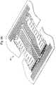
- FIG. 4is a detail view of the support member shown in FIG. 3 .
- FIGS. 5A-5Dschematically illustrate various stages of a method of manufacturing a packaged microelectronic device configured in accordance with an embodiment of the disclosure.
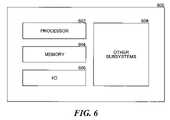
- FIG. 6is a schematic illustration of a system that can include one or more microelectronic devices configured in accordance with embodiments of the disclosure.
- the microelectronic diescan be flash memory (e.g., NAND flash memory), SRAM, DRAM (e.g., DDR-SDRAM), processors, imagers, and other types of devices.
- the term “coupled”may encompass various types of relationships between two or more components or features.
- the phrase “electrically coupled”may encompass a path conductively linking two or more components or features, or the phrase “mechanically coupled” may encompass a physical association or structural linking of two or more components or features.
- several other embodiments of the disclosurecan have configurations, components, features or procedures different than those described in this section. A person of ordinary skill in the art, therefore, will accordingly understand that the disclosure may have other embodiments with additional elements, or the disclosure may have other embodiments without several of the elements shown and described below with reference to FIGS. 2-5 .
- the device 200can also include an encapsulant, shell, or cap 400 formed, molded or otherwise deposited over the microelectronic dies 220 and at least a portion of the support structure 300 .
- the encapsulant 400enhances the integrity of the device 200 and protects the microelectronic dies 220 and the mechanical and electrical connections between the dies and the support member 300 from moisture, chemicals, and other contaminants.
- the second-fourth dies 220 b - dare offset with respect to a third axis Y by a distance sufficient to expose the array of electrical terminals 228 a - c on the immediately adjacent underlying die 220 a - c .
- Thisis particularly useful for dies that have bond-pad arrays at one end of the die, such as many flash memory devices.
- the lateral offset along the third axis Yenables a wirebonding machine to attach wirebonds to the terminals 228 a - d to electrically couple the microelectronic dies 220 a - d to each other and to a plurality of bond pads 308 on the support structure 300 .
- a plurality of wire bonds 310 or other types of electrical connectorscan accordingly extend between the electrical terminals 228 a - d and the bond pads 308 .
- the first and second dambars 320 and 324electrically short leads together and must be trimmed before the microelectronic device 200 can be operated.
- the term “tie-bar”may encompass features of the die paddle 307 that locate the first die 220 a with respect to the first and second sides 342 and 346 of the support structure 300 .
- FIG. 3also schematically shows the plurality of wire bonds 310 electrically coupling the plurality of bond pads 308 on the support structure 300 with the bonding pads 228 a - d on the microelectronic dies 220 a - d . Outlines of the four dies 220 a - d are indicated with phantom lines in FIG. 3 for the sake of illustration clarity.
- the first and second tie-bars 340 and 344are cut to singulate individual microelectronic devices 200 .
- the support structure 300further includes a plurality of elongated leads 360 that extend longitudinally across the length of the support structure 300 .
- the long leadsaccommodate the terminals 228 located at only one end of the dies 220 .
- the terms “longitudinally” and “latitudinally”are defined with respect to the general orientation of the plurality of elongated leads 360 (identified individually by reference numbers 360 a - c ) that extend across the die paddle 307 of the support structure 300 .
- the leads 360generally extend longitudinally from the first dambar 320 and span more than half the distance between the first and second ends 322 and 326 . In accordance with the embodiment of the disclosure shown in FIG.
- the length of individual ones of the leads 360may be approximately equal to or greater than the distance between the first and second ends 322 and 326 .
- the leads 360can extend like a dambar to the first or second tie-bars 340 and 344 , and can extend like a tie-bar to the first and second dambars 320 and 324 .
- each of the leads 360may include specific features depending on the lead routing and electrical coupling.
- the first lead 360 aincludes a first section 361 a connected to the first dambar 320 and a second section 362 a connected to the second dambar 324 .
- the first and second sections 361 a and 362 a of the first lead 360 amay be collinear or parallel, in which case a transition section 363 a coupling the first and second sections 361 a and 362 a may be relatively angularly oriented thereto (e.g., oblique or perpendicular with respect to the first and second sections 361 a and 362 a ).
- the first lead 360 aalso includes one or more bond pads 364 a .
- the bond pad 364 a of the first lead 360 a shown in FIG. 4is disposed on the first section 361 a , it can additionally or alternatively be disposed on the second section 362 a and/or the transition section 363 a . Accordingly, more area of the first lead 360 a can be available for direct die to leadframe metal bonding.
- the bond pad 364 amay be prepared, e.g., silver-plated, prior to being electrically coupled with one or more of the plurality of wire bonds 310 .
- the second lead 360 bincludes a first section 361 b that extends from the first dambar 320 , and includes a second section 362 b that extends from the first tie-bar 340 .
- the first section 361 bmay be angularly related to the second section 362 b , e.g., perpendicular to one another.
- a transition section 363 bcouples the first and second sections 361 b and 362 b .
- the second lead 360 balso includes a bond pad 364 b . Although the bond pad 364 b of the second lead 360 b is shown in FIG.
- the bond pad 364 bmay be prepared, e.g., silver-plated, prior to being electrically coupled with one or more of the plurality of wire bonds 310 .
- the third lead 360 cincludes a first section 361 c that extends from the first dambar 320 , and includes a second section 362 c that extends from the second tie-bar 344 .
- the first section 361 cmay be angularly related to the second section 362 c , e.g., perpendicular to one another.
- a transition section 363 ccouples the first and second sections 361 c and 362 c .
- the third lead 360 calso includes a bond pad 364 c . Although the bond pad 364 c of the third lead 360 c is shown in FIG.
- the bond pad 364 cmay be prepared, e.g., silver-plated, prior to being electrically coupled with one or more of the plurality of wire bonds 310 .
- each of the first, second and third leads 360 a - 360 cthere can be more than one of each of the first, second and third leads 360 a - 360 c .
- the support structure 300 according to FIG. 4is well suited to a multiple die NAND flash memory device.
- the relative numbers of the different leads 360 a - 360 cmay vary as appropriate for other microelectronic devices.
- a support structure 300may include only examples of the second and third leads 360 b and 360 c.
- FIG. 4also illustrates downsetting on a support structure 300 according to an embodiment of the disclosure. As shown in FIG. 4 , the displacement due to downsetting occurs in areas 380 of each of the first, second and third leads 360 a - 360 c that are proximate to the dambars and tie-bars. Displacement due to downsetting also occurs elsewhere at additional locations around the support structure 300 .
- Lead-locking tapee.g., R-970 manufactured by Tomoegawa Co., Ltd.
- R-970manufactured by Tomoegawa Co., Ltd.
- NAND flash memory diesdownsetting (e.g., NAND flash memory dies).
- Maintaining the correct spatial relationshipimproves lead planarity and thereby avoids poor wire-bonding yields; however, using lead-locking tape adds to the cost and complexity of manufacturing a microelectronic device and increases the thickness of the package stack-up. If the stack-up becomes too great, additional die back-grinding may be necessary to compensate for the thickness of the lead-locking tape.
- the leads 360are routed so as to extend from a dambar across more than half the longitudinal distance of the support structure either to connect to the opposite dambar or to connect near the oppose dambar to one of the tie-bars.
- a first lead 360 aextends from the first dambar (not shown in FIG. 4 ) to the second dambar 324
- an example of a second lead 360 bextends from the first dambar (not shown in FIG. 4 ) to the first tie-bar 340
- an example of a third lead 360 cextends from the first dambar (not shown in FIG. 4 ) to the second tie-bar 344 .
- the spatial relationships of the first, second and third leads 360 a - 360 care maintained, without using lead-locking tape, by virtue of the leads being fixed at both ends to the first and second dambars 320 and 324 and/or the first and second tie-bars 340 and 344 .
- the spatial relationshipis maintained during package manufacturing stages including downsetting, die attaching, wire-bonding, encapsulation, deflashing, trimming, lead forming, and singulation.
- at least one of the leads 360can be used as an effective ground for enhancing electrical performance.
- FIGS. 5A-5Dshow certain stages of a method of manufacturing a microelectronic device 200 , including a support structure 300 , in accordance with an embodiment of the disclosure.
- the support structure 300provides mechanical support to a die during assembly of the microelectronic device 200 .
- the support structure 300may be made of a metal alloy, e.g., Alloy 42, that provides good adherence to the encapsulant 400 , a coefficient of thermal expansion as close as possible to those of the die and the encapsulant 400 , high strength, good formability, and high electrical and thermal conductivities.
- the features of the support structure 300may be formed by stamping, etching, or another process.
- stampingcan encompass a mechanical process that uses one or more stamping/punching steps to form the features of the support structure 300 .
- etchingcan encompass selectively covering a metal sheet with a photoresist in accordance with a desired pattern, and exposing the metal sheet to a chemical etchant that removes areas not covered by photoresist. Additional processing of the support structure 300 may include silver-plating the bond pads and downsetting.
- the first microelectronic die 220 ais mechanically coupled, e.g., with an adhesive, to the die paddle of the support structure 300 and is electrically coupled to the leads 360 , e.g., by wire bonding 310 or by tape automated bonds.
- the second, third and fourth microelectronic dies 220 b - 220 dare sequentially stacked on the first die 220 a and similarly coupled.
- FIG. 5Cshows the encapsulant 400 molded over the support structure 300 as well as the four microelectronic dies 220 a - d .
- lead float of the second and third leads 360 b and 360 cis avoided and the spatial relationships of the second and third leads 360 b and 360 c are maintained because the second sections 362 b and 362 c remain connected to the first and second tie-bars 340 and 344 while molding the encapsulant 400 .
- Subsequent molding with the encapsulant 400fixes the spatial relationships of the leads 360 in the encapsulated volume. Excess encapsulant 400 may be removed by deflashing as is conventionally known.
- FIG. 5Dshows the microelectronic device 200 after trimming and forming the leads.
- trimmingmay include cutting and removing the first and second dambars 320 and 324 as well as the first and second tie-bars 340 and 344 . Trimming both the dambars and the tie-bars may occur concurrently or in separate operations. Trimming the first and second tie-bars 340 and 344 severs the couplings that electrically short each of the second and third leads 360 b and 360 c . Lead forming may also occur at the same time that the first and second dambars 320 and 324 are trimmed. Lead forming may include preparing, e.g., shaping, that portion of the leads 360 that project outside the encapsulant 400 for subsequently coupling the microelectronic device 200 to a printed circuit board or to another device.
- support structures in accordance with the disclosuredo not require additional manufacturing stages to separately cut lead tips nor require the use of lead-locking tape.
- Conventional support structuresmay include an additional formation that couples together the tips of a plurality of leads. Insofar as this additional formation electrically shorts the leads, the additional formation must be cut from the conventional support structure in order to electrically isolate the leads.
- this additional formationis disposed at an interior position, i.e., as opposed to being located at the periphery of the conventional support structure, a separate, additional manufacturing stage is required to cut the lead tips prior to encapsulation. Cutting the lead tips exasperates lead float and the need for using lead-locking tape in the conventional support structure.
- the lead-locking tape used in conventional support structuresadds another component, adds another manufacturing stage to implement use of the lead-locking tape, and increases the package stack-up thickness.
- conventional support structuressometimes require yet another manufacturing stage to backgrind the dies.
- Several embodiments of devices in accordance with the disclosureare directly ready for attaching the first microelectronic die 220 to the support structure 300 without the additional manufacturing stages of convention support members.
- Microelectronic devices and/or microfeature workpiecesmay be included in any of the components shown in FIG. 6 .
- the resulting system 600can perform any of a wide variety of computing, processing, storage, sensor, imagers, and/or other functions.
- representative systems 600include, without limitation, computers and/or other data processors, for example, desktop computers, laptop computers, Internet appliances, hand-held devices (e.g., palm-top computers, wearable computers, cellular or mobile phones, personal digital assistants), multi-processor systems, processor-based or programmable consumer electronics, network computers, and mini-computers.
- Other representative systems 600include cameras, light or other radiation sensors, servers and associated server subsystems, display devices, and/or memory devices.
- individual diescan include imager arrays, such as a CMOS imager.
- Components of the system 600may be housed in a single unit or distributed over multiple, interconnected units, e.g., through a communications network. Components can accordingly include local and/or remote memory storage devices and any of a wide variety of computer-readable media.
- attachment features described above with reference to particular embodimentscan include one or more additional features or components, or one or more of the features described above can be omitted.
- connections between the attachment feature, the interconnects, and other devicescan have arrangements different than those described above.
Landscapes
- Physics & Mathematics (AREA)
- Condensed Matter Physics & Semiconductors (AREA)
- General Physics & Mathematics (AREA)
- Engineering & Computer Science (AREA)
- Computer Hardware Design (AREA)
- Microelectronics & Electronic Packaging (AREA)
- Power Engineering (AREA)
- Wire Bonding (AREA)
- Lead Frames For Integrated Circuits (AREA)
Abstract
Description
Claims (14)
Priority Applications (3)
| Application Number | Priority Date | Filing Date | Title |
|---|---|---|---|
| US12/183,981US7612436B1 (en) | 2008-07-31 | 2008-07-31 | Packaged microelectronic devices with a lead frame |
| US12/564,417US7968376B2 (en) | 2008-07-31 | 2009-09-22 | Packaged microelectronic devices and methods for manufacturing packaged microelectronic devices |
| US13/171,293US8283761B2 (en) | 2008-07-31 | 2011-06-28 | Packaged microelectronic devices and methods for manufacturing packaged microelectronic devices |
Applications Claiming Priority (1)
| Application Number | Priority Date | Filing Date | Title |
|---|---|---|---|
| US12/183,981US7612436B1 (en) | 2008-07-31 | 2008-07-31 | Packaged microelectronic devices with a lead frame |
Related Child Applications (1)
| Application Number | Title | Priority Date | Filing Date |
|---|---|---|---|
| US12/564,417DivisionUS7968376B2 (en) | 2008-07-31 | 2009-09-22 | Packaged microelectronic devices and methods for manufacturing packaged microelectronic devices |
Publications (1)
| Publication Number | Publication Date |
|---|---|
| US7612436B1true US7612436B1 (en) | 2009-11-03 |
Family
ID=41227423
Family Applications (3)
| Application Number | Title | Priority Date | Filing Date |
|---|---|---|---|
| US12/183,981ActiveUS7612436B1 (en) | 2008-07-31 | 2008-07-31 | Packaged microelectronic devices with a lead frame |
| US12/564,417ActiveUS7968376B2 (en) | 2008-07-31 | 2009-09-22 | Packaged microelectronic devices and methods for manufacturing packaged microelectronic devices |
| US13/171,293ActiveUS8283761B2 (en) | 2008-07-31 | 2011-06-28 | Packaged microelectronic devices and methods for manufacturing packaged microelectronic devices |
Family Applications After (2)
| Application Number | Title | Priority Date | Filing Date |
|---|---|---|---|
| US12/564,417ActiveUS7968376B2 (en) | 2008-07-31 | 2009-09-22 | Packaged microelectronic devices and methods for manufacturing packaged microelectronic devices |
| US13/171,293ActiveUS8283761B2 (en) | 2008-07-31 | 2011-06-28 | Packaged microelectronic devices and methods for manufacturing packaged microelectronic devices |
Country Status (1)
| Country | Link |
|---|---|
| US (3) | US7612436B1 (en) |
Cited By (17)
| Publication number | Priority date | Publication date | Assignee | Title |
|---|---|---|---|---|
| US20090001530A1 (en)* | 2007-06-18 | 2009-01-01 | Kabushiki Kaisha Toshiba | Semiconductor device |
| US20090224377A1 (en)* | 2008-03-09 | 2009-09-10 | Wen-Jeng Fan | Semiconductor device with wire-bonding on multi-zigzag fingers |
| US20100127375A1 (en)* | 2008-11-21 | 2010-05-27 | Manolito Galera | Wafer level chip scale semiconductor packages |
| US20100193924A1 (en)* | 2009-02-05 | 2010-08-05 | Kabushiki Kaisha Toshiba | Semiconductor device |
| US20110254144A1 (en)* | 2008-07-31 | 2011-10-20 | Micron Technology, Inc. | Packaged microelectronic devices and methods for manufacturing packaged microelectronic devices |
| EP2413356A1 (en)* | 2010-07-28 | 2012-02-01 | SanDisk Technologies, Inc. | Semiconductor device with die stack arrangement including staggered die and efficient wire bonding |
| TWI409928B (en)* | 2009-11-17 | 2013-09-21 | Powertech Technology Inc | Universal chip-on-lead leadframe |
| US20140252640A1 (en)* | 2013-03-05 | 2014-09-11 | Samsung Electronics Co., Ltd. | Semiconductor package having a multi-channel and a related electronic system |
| US8930647B1 (en) | 2011-04-06 | 2015-01-06 | P4tents1, LLC | Multiple class memory systems |
| US9158546B1 (en) | 2011-04-06 | 2015-10-13 | P4tents1, LLC | Computer program product for fetching from a first physical memory between an execution of a plurality of threads associated with a second physical memory |
| US9164679B2 (en) | 2011-04-06 | 2015-10-20 | Patents1, Llc | System, method and computer program product for multi-thread operation involving first memory of a first memory class and second memory of a second memory class |
| US9170744B1 (en) | 2011-04-06 | 2015-10-27 | P4tents1, LLC | Computer program product for controlling a flash/DRAM/embedded DRAM-equipped system |
| US9176671B1 (en) | 2011-04-06 | 2015-11-03 | P4tents1, LLC | Fetching data between thread execution in a flash/DRAM/embedded DRAM-equipped system |
| US9417754B2 (en) | 2011-08-05 | 2016-08-16 | P4tents1, LLC | User interface system, method, and computer program product |
| US9432298B1 (en) | 2011-12-09 | 2016-08-30 | P4tents1, LLC | System, method, and computer program product for improving memory systems |
| CN102347317B (en)* | 2010-07-28 | 2016-12-14 | 桑迪士克科技有限责任公司 | Semiconductor device |
| US20170125378A1 (en)* | 2014-01-16 | 2017-05-04 | Samsung Electronics Co., Ltd. | Semiconductor package including stepwise stacked chips |
Families Citing this family (3)
| Publication number | Priority date | Publication date | Assignee | Title |
|---|---|---|---|---|
| KR101933364B1 (en) | 2013-01-09 | 2018-12-27 | 샌디스크 세미컨덕터 (상하이) 컴퍼니, 리미티드 | Semiconductor device including independent film layer for embedding and/or spacing semiconductor die |
| KR102211934B1 (en)* | 2014-03-06 | 2021-02-04 | 삼성전자주식회사 | Semiconductor package |
| CN110010620B (en)* | 2017-11-21 | 2021-04-13 | 长江存储科技有限责任公司 | Manufacturing method of 3D NAND flash memory with high stack number and 3D NAND flash memory |
Citations (29)
| Publication number | Priority date | Publication date | Assignee | Title |
|---|---|---|---|---|
| JPH03195052A (en)* | 1989-12-25 | 1991-08-26 | Dainippon Printing Co Ltd | Lead frame and its manufacturing method |
| US5126821A (en)* | 1985-03-25 | 1992-06-30 | Hitachi, Ltd. | Semiconductor device having inner leads extending over a surface of a semiconductor pellet |
| US20030006492A1 (en) | 2001-07-09 | 2003-01-09 | Kazuto Ogasawara | Semiconductor device and method of manufacturing the same |
| US6569727B1 (en) | 1995-08-17 | 2003-05-27 | Micron Technology, Inc. | Method of making a single-deposition-layer-metal dynamic random access memory |
| US20030137042A1 (en)* | 2001-06-21 | 2003-07-24 | Mess Leonard E. | Stacked mass storage flash memory package |
| US6627976B1 (en) | 1999-10-15 | 2003-09-30 | Amkor Technology, Inc. | Leadframe for semiconductor package and mold for molding the same |
| KR20030078213A (en) | 2002-03-28 | 2003-10-08 | 삼성테크윈 주식회사 | Lead-frame for semiconductor package and method for manufacturing lead-frame |
| US6838751B2 (en) | 2002-03-06 | 2005-01-04 | Freescale Semiconductor Inc. | Multi-row leadframe |
| KR20050017838A (en) | 2003-08-11 | 2005-02-23 | 광전자 주식회사 | Semi-conductor package to have high protection gainst heat structure |
| US20050073031A1 (en) | 2003-10-06 | 2005-04-07 | Renesas Technology Corp. | Lead frame, semiconductor device, and method for manufacturing semiconductor device |
| US6882035B2 (en)* | 2003-07-09 | 2005-04-19 | Agilent Technologies, Inc. | Die package |
| US6903448B1 (en) | 2002-11-12 | 2005-06-07 | Marvell International Ltd. | High performance leadframe in electronic package |
| US6949813B2 (en) | 2000-08-25 | 2005-09-27 | Micron Technology, Inc. | Lead-over-chip lead frames |
| US7002239B1 (en) | 2003-02-14 | 2006-02-21 | National Semiconductor Corporation | Leadless leadframe packaging panel featuring peripheral dummy leads |
| US20060043542A1 (en) | 2004-08-31 | 2006-03-02 | Corisis David J | Floating lead finger on a lead frame, method of making, and lead frame strip and lead frame assembly including same |
| WO2006052382A2 (en) | 2004-11-09 | 2006-05-18 | Freescale Semiconductor, Inc. | Leadframe for a semiconductor device |
| US20060216866A1 (en) | 2004-04-30 | 2006-09-28 | Atmel Corporation | Universal interconnect die |
| US20060220191A1 (en) | 2005-04-01 | 2006-10-05 | Honeywell International Inc. | Electronic package with a stepped-pitch leadframe |
| US20060228832A1 (en) | 2005-03-31 | 2006-10-12 | Koh Wei H | Leadframe semiconductor package stand and method for making the same |
| US20060281228A1 (en) | 2005-05-24 | 2006-12-14 | Siliconware Precision Industries Co., Ltd. | Lead-frame type semiconductor package and lead frame thereof |
| US20070001272A1 (en) | 2005-06-30 | 2007-01-04 | Lee Ming H | Die package with asymmetric leadframe connection |
| US20070057361A1 (en) | 2005-02-25 | 2007-03-15 | Texas Instruments Incorporated | integrated circuit package and method of manufacture thereof |
| US20070102794A1 (en) | 2005-11-10 | 2007-05-10 | Chao-Yang Hsiao | Lead arrangement and chip package using the same |
| US20070164411A1 (en) | 2006-01-16 | 2007-07-19 | Siliconware Precision Industries Co., Ltd. | Semiconductor package structure and fabrication method thereof |
| US20080012099A1 (en) | 2006-07-11 | 2008-01-17 | Shing Yeh | Electronic assembly and manufacturing method having a reduced need for wire bonds |
| US20080012110A1 (en) | 2006-07-17 | 2008-01-17 | Micron Technology, Inc. | Microelectronic packages with leadframes, including leadframes configured for stacked die packages, and associated systems and methods |
| US20080017994A1 (en) | 2006-07-24 | 2008-01-24 | Byung Tai Do | Leaded stacked packages having elevated die paddle |
| US20080036052A1 (en) | 2006-08-09 | 2008-02-14 | Stats Chippac Ltd. | Integrated circuit package system with supported stacked die |
| US20080038872A1 (en) | 2006-08-08 | 2008-02-14 | Nec Electronics Corporation | Method of manufacturing semiconductor device |
Family Cites Families (8)
| Publication number | Priority date | Publication date | Assignee | Title |
|---|---|---|---|---|
| DE69231290D1 (en)* | 1991-12-27 | 2000-08-31 | Fujitsu Ltd | Semiconductor device and method for its manufacture |
| US5457340A (en)* | 1992-12-07 | 1995-10-10 | Integrated Device Technology, Inc. | Leadframe with power and ground planes |
| JP2820645B2 (en)* | 1994-08-30 | 1998-11-05 | アナム インダストリアル カンパニー インコーポレーティド | Semiconductor lead frame |
| US5585667A (en)* | 1994-12-23 | 1996-12-17 | National Semiconductor Corporation | Lead frame for handling crossing bonding wires |
| US7215012B2 (en)* | 2003-01-03 | 2007-05-08 | Gem Services, Inc. | Space-efficient package for laterally conducting device |
| US20040201080A1 (en)* | 2003-04-08 | 2004-10-14 | Suresh Basoor | Leadless leadframe electronic package and IR transceiver incorporating same |
| US6921967B2 (en)* | 2003-09-24 | 2005-07-26 | Amkor Technology, Inc. | Reinforced die pad support structure |
| US7612436B1 (en)* | 2008-07-31 | 2009-11-03 | Micron Technology, Inc. | Packaged microelectronic devices with a lead frame |
- 2008
- 2008-07-31USUS12/183,981patent/US7612436B1/enactiveActive
- 2009
- 2009-09-22USUS12/564,417patent/US7968376B2/enactiveActive
- 2011
- 2011-06-28USUS13/171,293patent/US8283761B2/enactiveActive
Patent Citations (32)
| Publication number | Priority date | Publication date | Assignee | Title |
|---|---|---|---|---|
| US5126821A (en)* | 1985-03-25 | 1992-06-30 | Hitachi, Ltd. | Semiconductor device having inner leads extending over a surface of a semiconductor pellet |
| JPH03195052A (en)* | 1989-12-25 | 1991-08-26 | Dainippon Printing Co Ltd | Lead frame and its manufacturing method |
| US6569727B1 (en) | 1995-08-17 | 2003-05-27 | Micron Technology, Inc. | Method of making a single-deposition-layer-metal dynamic random access memory |
| US6627976B1 (en) | 1999-10-15 | 2003-09-30 | Amkor Technology, Inc. | Leadframe for semiconductor package and mold for molding the same |
| US6949813B2 (en) | 2000-08-25 | 2005-09-27 | Micron Technology, Inc. | Lead-over-chip lead frames |
| US20060186530A1 (en) | 2000-08-25 | 2006-08-24 | Micron Technology, Inc. | Memory device power distribution in memory assemblies |
| US20030137042A1 (en)* | 2001-06-21 | 2003-07-24 | Mess Leonard E. | Stacked mass storage flash memory package |
| US20030006492A1 (en) | 2001-07-09 | 2003-01-09 | Kazuto Ogasawara | Semiconductor device and method of manufacturing the same |
| US6838751B2 (en) | 2002-03-06 | 2005-01-04 | Freescale Semiconductor Inc. | Multi-row leadframe |
| KR20030078213A (en) | 2002-03-28 | 2003-10-08 | 삼성테크윈 주식회사 | Lead-frame for semiconductor package and method for manufacturing lead-frame |
| US6903448B1 (en) | 2002-11-12 | 2005-06-07 | Marvell International Ltd. | High performance leadframe in electronic package |
| US7002239B1 (en) | 2003-02-14 | 2006-02-21 | National Semiconductor Corporation | Leadless leadframe packaging panel featuring peripheral dummy leads |
| US6882035B2 (en)* | 2003-07-09 | 2005-04-19 | Agilent Technologies, Inc. | Die package |
| KR20050017838A (en) | 2003-08-11 | 2005-02-23 | 광전자 주식회사 | Semi-conductor package to have high protection gainst heat structure |
| US20050073031A1 (en) | 2003-10-06 | 2005-04-07 | Renesas Technology Corp. | Lead frame, semiconductor device, and method for manufacturing semiconductor device |
| US20060216866A1 (en) | 2004-04-30 | 2006-09-28 | Atmel Corporation | Universal interconnect die |
| US20060131706A1 (en) | 2004-08-31 | 2006-06-22 | Corisis David J | Methods of making and using a floating lead finger on a lead frame |
| US20060043542A1 (en) | 2004-08-31 | 2006-03-02 | Corisis David J | Floating lead finger on a lead frame, method of making, and lead frame strip and lead frame assembly including same |
| WO2006052382A2 (en) | 2004-11-09 | 2006-05-18 | Freescale Semiconductor, Inc. | Leadframe for a semiconductor device |
| US20070057361A1 (en) | 2005-02-25 | 2007-03-15 | Texas Instruments Incorporated | integrated circuit package and method of manufacture thereof |
| US20060228832A1 (en) | 2005-03-31 | 2006-10-12 | Koh Wei H | Leadframe semiconductor package stand and method for making the same |
| US20060220191A1 (en) | 2005-04-01 | 2006-10-05 | Honeywell International Inc. | Electronic package with a stepped-pitch leadframe |
| US20060281228A1 (en) | 2005-05-24 | 2006-12-14 | Siliconware Precision Industries Co., Ltd. | Lead-frame type semiconductor package and lead frame thereof |
| US20070001272A1 (en) | 2005-06-30 | 2007-01-04 | Lee Ming H | Die package with asymmetric leadframe connection |
| US7375415B2 (en)* | 2005-06-30 | 2008-05-20 | Sandisk Corporation | Die package with asymmetric leadframe connection |
| US20070102794A1 (en) | 2005-11-10 | 2007-05-10 | Chao-Yang Hsiao | Lead arrangement and chip package using the same |
| US20070164411A1 (en) | 2006-01-16 | 2007-07-19 | Siliconware Precision Industries Co., Ltd. | Semiconductor package structure and fabrication method thereof |
| US20080012099A1 (en) | 2006-07-11 | 2008-01-17 | Shing Yeh | Electronic assembly and manufacturing method having a reduced need for wire bonds |
| US20080012110A1 (en) | 2006-07-17 | 2008-01-17 | Micron Technology, Inc. | Microelectronic packages with leadframes, including leadframes configured for stacked die packages, and associated systems and methods |
| US20080017994A1 (en) | 2006-07-24 | 2008-01-24 | Byung Tai Do | Leaded stacked packages having elevated die paddle |
| US20080038872A1 (en) | 2006-08-08 | 2008-02-14 | Nec Electronics Corporation | Method of manufacturing semiconductor device |
| US20080036052A1 (en) | 2006-08-09 | 2008-02-14 | Stats Chippac Ltd. | Integrated circuit package system with supported stacked die |
Non-Patent Citations (5)
| Title |
|---|
| Juskey, F., "Flip Chip on Standard Lead Frame: Laminate Performance at a Lower Cost," 2003 IEEE/CPMT/SEMI International Electronics Manufacturing Technology Symposium, Jul. 16-18, 2003, pp. 237-240. |
| Kim, J. et al., "Multi-Flip Chip on Lead Frame Overmolded IC Package: A Novel Packaging Design to Achieve High Performance and Cost Effective Module Package," IEEE 2005 Electronic Components and Technology Conference, May 31-Jun. 3, 2005, pp. 1819-1821. |
| Kuehnlein, G., "Recent Progress in Popcorn Performance and Cost Reduction of QFP160 using Ni/Pd plated Dambar Less Lead Frames," Proceedings of the 2nd Electronics Packaging Technology Conference, pp. 325-330, Dec. 8-10, 1998. |
| Mahulikar, D., "Trends in Lead Frame Technology for Plastic Packaging," Proceedings of the 3rd International Symposium on Advanced Packaging Materials, pp. 94-97, Mar. 9-12, 1997. |
| Rodriguez de Miranda, W.R. et al., "Lead Forming and Outer Lead Bond Pattern Design for Tape-Bonded Hybrids," IEEE Transactions on Components, Hybrids, and Manufacturing Technology, vol. CHMT-1, No. 4, pp. 377-382, Dec. 1978. |
Cited By (82)
| Publication number | Priority date | Publication date | Assignee | Title |
|---|---|---|---|---|
| US7989932B2 (en)* | 2007-06-18 | 2011-08-02 | Kabushiki Kaisha Toshiba | Semiconductor device |
| US20090001530A1 (en)* | 2007-06-18 | 2009-01-01 | Kabushiki Kaisha Toshiba | Semiconductor device |
| US20090224377A1 (en)* | 2008-03-09 | 2009-09-10 | Wen-Jeng Fan | Semiconductor device with wire-bonding on multi-zigzag fingers |
| US7821112B2 (en)* | 2008-03-09 | 2010-10-26 | Powertech Technology Inc | Semiconductor device with wire-bonding on multi-zigzag fingers |
| US20110254144A1 (en)* | 2008-07-31 | 2011-10-20 | Micron Technology, Inc. | Packaged microelectronic devices and methods for manufacturing packaged microelectronic devices |
| US8283761B2 (en)* | 2008-07-31 | 2012-10-09 | Micron Technology, Inc. | Packaged microelectronic devices and methods for manufacturing packaged microelectronic devices |
| US20100127375A1 (en)* | 2008-11-21 | 2010-05-27 | Manolito Galera | Wafer level chip scale semiconductor packages |
| US8912636B2 (en)* | 2009-02-05 | 2014-12-16 | Kabushiki Kaisha Toshiba | Semiconductor device |
| US20100193924A1 (en)* | 2009-02-05 | 2010-08-05 | Kabushiki Kaisha Toshiba | Semiconductor device |
| TWI409928B (en)* | 2009-11-17 | 2013-09-21 | Powertech Technology Inc | Universal chip-on-lead leadframe |
| US8853863B2 (en) | 2010-07-28 | 2014-10-07 | Sandisk Technologies Inc. | Semiconductor device with die stack arrangement including staggered die and efficient wire bonding |
| US8415808B2 (en) | 2010-07-28 | 2013-04-09 | Sandisk Technologies Inc. | Semiconductor device with die stack arrangement including staggered die and efficient wire bonding |
| CN102347317B (en)* | 2010-07-28 | 2016-12-14 | 桑迪士克科技有限责任公司 | Semiconductor device |
| CN102347317A (en)* | 2010-07-28 | 2012-02-08 | 桑迪士克科技股份有限公司 | Semiconductor device |
| EP2413356A1 (en)* | 2010-07-28 | 2012-02-01 | SanDisk Technologies, Inc. | Semiconductor device with die stack arrangement including staggered die and efficient wire bonding |
| EP2618374A3 (en)* | 2010-07-28 | 2016-06-08 | SanDisk Technologies Inc. | Semiconductor device with die stack arrangement including staggered die and efficient wire bonding |
| US9170744B1 (en) | 2011-04-06 | 2015-10-27 | P4tents1, LLC | Computer program product for controlling a flash/DRAM/embedded DRAM-equipped system |
| US9164679B2 (en) | 2011-04-06 | 2015-10-20 | Patents1, Llc | System, method and computer program product for multi-thread operation involving first memory of a first memory class and second memory of a second memory class |
| US9176671B1 (en) | 2011-04-06 | 2015-11-03 | P4tents1, LLC | Fetching data between thread execution in a flash/DRAM/embedded DRAM-equipped system |
| US9182914B1 (en) | 2011-04-06 | 2015-11-10 | P4tents1, LLC | System, method and computer program product for multi-thread operation involving first memory of a first memory class and second memory of a second memory class |
| US9189442B1 (en) | 2011-04-06 | 2015-11-17 | P4tents1, LLC | Fetching data between thread execution in a flash/DRAM/embedded DRAM-equipped system |
| US9195395B1 (en) | 2011-04-06 | 2015-11-24 | P4tents1, LLC | Flash/DRAM/embedded DRAM-equipped system and method |
| US9223507B1 (en) | 2011-04-06 | 2015-12-29 | P4tents1, LLC | System, method and computer program product for fetching data between an execution of a plurality of threads |
| US9158546B1 (en) | 2011-04-06 | 2015-10-13 | P4tents1, LLC | Computer program product for fetching from a first physical memory between an execution of a plurality of threads associated with a second physical memory |
| US8930647B1 (en) | 2011-04-06 | 2015-01-06 | P4tents1, LLC | Multiple class memory systems |
| US10222892B1 (en) | 2011-08-05 | 2019-03-05 | P4tents1, LLC | System, method, and computer program product for a multi-pressure selection touch screen |
| US10551966B1 (en) | 2011-08-05 | 2020-02-04 | P4tents1, LLC | Gesture-equipped touch screen system, method, and computer program product |
| US11740727B1 (en) | 2011-08-05 | 2023-08-29 | P4Tents1 Llc | Devices, methods, and graphical user interfaces for manipulating user interface objects with visual and/or haptic feedback |
| US11061503B1 (en) | 2011-08-05 | 2021-07-13 | P4tents1, LLC | Devices, methods, and graphical user interfaces for manipulating user interface objects with visual and/or haptic feedback |
| US10031607B1 (en) | 2011-08-05 | 2018-07-24 | P4tents1, LLC | System, method, and computer program product for a multi-pressure selection touch screen |
| US10120480B1 (en) | 2011-08-05 | 2018-11-06 | P4tents1, LLC | Application-specific pressure-sensitive touch screen system, method, and computer program product |
| US10146353B1 (en) | 2011-08-05 | 2018-12-04 | P4tents1, LLC | Touch screen system, method, and computer program product |
| US10156921B1 (en) | 2011-08-05 | 2018-12-18 | P4tents1, LLC | Tri-state gesture-equipped touch screen system, method, and computer program product |
| US10996787B1 (en) | 2011-08-05 | 2021-05-04 | P4tents1, LLC | Gesture-equipped touch screen system, method, and computer program product |
| US10162448B1 (en) | 2011-08-05 | 2018-12-25 | P4tents1, LLC | System, method, and computer program product for a pressure-sensitive touch screen for messages |
| US10203794B1 (en) | 2011-08-05 | 2019-02-12 | P4tents1, LLC | Pressure-sensitive home interface system, method, and computer program product |
| US10209808B1 (en) | 2011-08-05 | 2019-02-19 | P4tents1, LLC | Pressure-based interface system, method, and computer program product with virtual display layers |
| US10209806B1 (en) | 2011-08-05 | 2019-02-19 | P4tents1, LLC | Tri-state gesture-equipped touch screen system, method, and computer program product |
| US10209807B1 (en) | 2011-08-05 | 2019-02-19 | P4tents1, LLC | Pressure sensitive touch screen system, method, and computer program product for hyperlinks |
| US10209809B1 (en) | 2011-08-05 | 2019-02-19 | P4tents1, LLC | Pressure-sensitive touch screen system, method, and computer program product for objects |
| US9417754B2 (en) | 2011-08-05 | 2016-08-16 | P4tents1, LLC | User interface system, method, and computer program product |
| US10222894B1 (en) | 2011-08-05 | 2019-03-05 | P4tents1, LLC | System, method, and computer program product for a multi-pressure selection touch screen |
| US10222895B1 (en) | 2011-08-05 | 2019-03-05 | P4tents1, LLC | Pressure-based touch screen system, method, and computer program product with virtual display layers |
| US10222893B1 (en) | 2011-08-05 | 2019-03-05 | P4tents1, LLC | Pressure-based touch screen system, method, and computer program product with virtual display layers |
| US10222891B1 (en) | 2011-08-05 | 2019-03-05 | P4tents1, LLC | Setting interface system, method, and computer program product for a multi-pressure selection touch screen |
| US10275087B1 (en) | 2011-08-05 | 2019-04-30 | P4tents1, LLC | Devices, methods, and graphical user interfaces for manipulating user interface objects with visual and/or haptic feedback |
| US10275086B1 (en) | 2011-08-05 | 2019-04-30 | P4tents1, LLC | Gesture-equipped touch screen system, method, and computer program product |
| US10338736B1 (en) | 2011-08-05 | 2019-07-02 | P4tents1, LLC | Devices, methods, and graphical user interfaces for manipulating user interface objects with visual and/or haptic feedback |
| US10345961B1 (en) | 2011-08-05 | 2019-07-09 | P4tents1, LLC | Devices and methods for navigating between user interfaces |
| US10365758B1 (en) | 2011-08-05 | 2019-07-30 | P4tents1, LLC | Devices, methods, and graphical user interfaces for manipulating user interface objects with visual and/or haptic feedback |
| US10386960B1 (en) | 2011-08-05 | 2019-08-20 | P4tents1, LLC | Devices, methods, and graphical user interfaces for manipulating user interface objects with visual and/or haptic feedback |
| US10521047B1 (en) | 2011-08-05 | 2019-12-31 | P4tents1, LLC | Gesture-equipped touch screen system, method, and computer program product |
| US10534474B1 (en) | 2011-08-05 | 2020-01-14 | P4tents1, LLC | Gesture-equipped touch screen system, method, and computer program product |
| US10540039B1 (en) | 2011-08-05 | 2020-01-21 | P4tents1, LLC | Devices and methods for navigating between user interface |
| US10936114B1 (en) | 2011-08-05 | 2021-03-02 | P4tents1, LLC | Gesture-equipped touch screen system, method, and computer program product |
| US10592039B1 (en) | 2011-08-05 | 2020-03-17 | P4tents1, LLC | Gesture-equipped touch screen system, method, and computer program product for displaying multiple active applications |
| US10606396B1 (en) | 2011-08-05 | 2020-03-31 | P4tents1, LLC | Gesture-equipped touch screen methods for duration-based functions |
| US10642413B1 (en) | 2011-08-05 | 2020-05-05 | P4tents1, LLC | Gesture-equipped touch screen system, method, and computer program product |
| US10649580B1 (en) | 2011-08-05 | 2020-05-12 | P4tents1, LLC | Devices, methods, and graphical use interfaces for manipulating user interface objects with visual and/or haptic feedback |
| US10649581B1 (en) | 2011-08-05 | 2020-05-12 | P4tents1, LLC | Devices, methods, and graphical user interfaces for manipulating user interface objects with visual and/or haptic feedback |
| US10649571B1 (en) | 2011-08-05 | 2020-05-12 | P4tents1, LLC | Devices, methods, and graphical user interfaces for manipulating user interface objects with visual and/or haptic feedback |
| US10649578B1 (en) | 2011-08-05 | 2020-05-12 | P4tents1, LLC | Gesture-equipped touch screen system, method, and computer program product |
| US10649579B1 (en) | 2011-08-05 | 2020-05-12 | P4tents1, LLC | Devices, methods, and graphical user interfaces for manipulating user interface objects with visual and/or haptic feedback |
| US10656752B1 (en) | 2011-08-05 | 2020-05-19 | P4tents1, LLC | Gesture-equipped touch screen system, method, and computer program product |
| US10656757B1 (en) | 2011-08-05 | 2020-05-19 | P4tents1, LLC | Gesture-equipped touch screen system, method, and computer program product |
| US10656755B1 (en) | 2011-08-05 | 2020-05-19 | P4tents1, LLC | Gesture-equipped touch screen system, method, and computer program product |
| US10656756B1 (en) | 2011-08-05 | 2020-05-19 | P4tents1, LLC | Gesture-equipped touch screen system, method, and computer program product |
| US10656754B1 (en) | 2011-08-05 | 2020-05-19 | P4tents1, LLC | Devices and methods for navigating between user interfaces |
| US10656753B1 (en) | 2011-08-05 | 2020-05-19 | P4tents1, LLC | Gesture-equipped touch screen system, method, and computer program product |
| US10656759B1 (en) | 2011-08-05 | 2020-05-19 | P4tents1, LLC | Devices, methods, and graphical user interfaces for manipulating user interface objects with visual and/or haptic feedback |
| US10656758B1 (en) | 2011-08-05 | 2020-05-19 | P4tents1, LLC | Gesture-equipped touch screen system, method, and computer program product |
| US10664097B1 (en) | 2011-08-05 | 2020-05-26 | P4tents1, LLC | Devices, methods, and graphical user interfaces for manipulating user interface objects with visual and/or haptic feedback |
| US10671212B1 (en) | 2011-08-05 | 2020-06-02 | P4tents1, LLC | Gesture-equipped touch screen system, method, and computer program product |
| US10671213B1 (en) | 2011-08-05 | 2020-06-02 | P4tents1, LLC | Devices, methods, and graphical user interfaces for manipulating user interface objects with visual and/or haptic feedback |
| US10725581B1 (en) | 2011-08-05 | 2020-07-28 | P4tents1, LLC | Devices, methods and graphical user interfaces for manipulating user interface objects with visual and/or haptic feedback |
| US10782819B1 (en) | 2011-08-05 | 2020-09-22 | P4tents1, LLC | Gesture-equipped touch screen system, method, and computer program product |
| US10788931B1 (en) | 2011-08-05 | 2020-09-29 | P4tents1, LLC | Devices, methods, and graphical user interfaces for manipulating user interface objects with visual and/or haptic feedback |
| US10838542B1 (en) | 2011-08-05 | 2020-11-17 | P4tents1, LLC | Gesture-equipped touch screen system, method, and computer program product |
| US9432298B1 (en) | 2011-12-09 | 2016-08-30 | P4tents1, LLC | System, method, and computer program product for improving memory systems |
| US20140252640A1 (en)* | 2013-03-05 | 2014-09-11 | Samsung Electronics Co., Ltd. | Semiconductor package having a multi-channel and a related electronic system |
| US10157883B2 (en)* | 2014-01-16 | 2018-12-18 | Samsung Electronics Co., Ltd. | Semiconductor package including stepwise stacked chips |
| US20170125378A1 (en)* | 2014-01-16 | 2017-05-04 | Samsung Electronics Co., Ltd. | Semiconductor package including stepwise stacked chips |
Also Published As
| Publication number | Publication date |
|---|---|
| US20100029043A1 (en) | 2010-02-04 |
| US8283761B2 (en) | 2012-10-09 |
| US7968376B2 (en) | 2011-06-28 |
| US20110254144A1 (en) | 2011-10-20 |
Similar Documents
| Publication | Publication Date | Title |
|---|---|---|
| US7612436B1 (en) | Packaged microelectronic devices with a lead frame | |
| US10396059B2 (en) | Microelectronic die packages with metal leads, including metal leads for stacked die packages, and associated systems and methods | |
| US8525320B2 (en) | Microelectronic die packages with leadframes, including leadframe-based interposer for stacked die packages, and associated systems and methods | |
| US7834469B2 (en) | Stacked type chip package structure including a chip package and a chip that are stacked on a lead frame | |
| US8659133B2 (en) | Etched surface mount islands in a leadframe package | |
| KR101440933B1 (en) | Integrated circuit package system employing bump technology | |
| US20130200507A1 (en) | Two-sided die in a four-sided leadframe based package | |
| US8349655B2 (en) | Method of fabricating a two-sided die in a four-sided leadframe based package | |
| US10269718B2 (en) | Rectangular semiconductor package and a method of manufacturing the same | |
| US20120313233A1 (en) | Semiconductor Package, Stacking Semiconductor Package, And Method Of Fabricating The Same | |
| JP5217291B2 (en) | Resin-sealed semiconductor device and manufacturing method thereof, substrate for semiconductor device, and laminated resin-sealed semiconductor device | |
| KR100566780B1 (en) | Manufacturing method of stacked multi chip package and stacked multi chip package using same | |
| US20140183714A1 (en) | Die package structure | |
| KR20010038572A (en) | semiconductor package and its manufacturing method | |
| KR20060074085A (en) | Stack package |
Legal Events
| Date | Code | Title | Description |
|---|---|---|---|
| AS | Assignment | Owner name:MICRON TECHNOLOGY, INC., IDAHO Free format text:ASSIGNMENT OF ASSIGNORS INTEREST;ASSIGNORS:LEE, TECK KHENG;CHIN, VOON SIONG;WANG, AI CHIE;REEL/FRAME:021325/0316;SIGNING DATES FROM 20080722 TO 20080724 | |
| FEPP | Fee payment procedure | Free format text:PAYOR NUMBER ASSIGNED (ORIGINAL EVENT CODE: ASPN); ENTITY STATUS OF PATENT OWNER: LARGE ENTITY | |
| STCF | Information on status: patent grant | Free format text:PATENTED CASE | |
| FPAY | Fee payment | Year of fee payment:4 | |
| AS | Assignment | Owner name:U.S. BANK NATIONAL ASSOCIATION, AS COLLATERAL AGENT, CALIFORNIA Free format text:SECURITY INTEREST;ASSIGNOR:MICRON TECHNOLOGY, INC.;REEL/FRAME:038669/0001 Effective date:20160426 Owner name:U.S. BANK NATIONAL ASSOCIATION, AS COLLATERAL AGEN Free format text:SECURITY INTEREST;ASSIGNOR:MICRON TECHNOLOGY, INC.;REEL/FRAME:038669/0001 Effective date:20160426 | |
| AS | Assignment | Owner name:MORGAN STANLEY SENIOR FUNDING, INC., AS COLLATERAL AGENT, MARYLAND Free format text:PATENT SECURITY AGREEMENT;ASSIGNOR:MICRON TECHNOLOGY, INC.;REEL/FRAME:038954/0001 Effective date:20160426 Owner name:MORGAN STANLEY SENIOR FUNDING, INC., AS COLLATERAL Free format text:PATENT SECURITY AGREEMENT;ASSIGNOR:MICRON TECHNOLOGY, INC.;REEL/FRAME:038954/0001 Effective date:20160426 | |
| FPAY | Fee payment | Year of fee payment:8 | |
| AS | Assignment | Owner name:U.S. BANK NATIONAL ASSOCIATION, AS COLLATERAL AGENT, CALIFORNIA Free format text:CORRECTIVE ASSIGNMENT TO CORRECT THE REPLACE ERRONEOUSLY FILED PATENT #7358718 WITH THE CORRECT PATENT #7358178 PREVIOUSLY RECORDED ON REEL 038669 FRAME 0001. ASSIGNOR(S) HEREBY CONFIRMS THE SECURITY INTEREST;ASSIGNOR:MICRON TECHNOLOGY, INC.;REEL/FRAME:043079/0001 Effective date:20160426 Owner name:U.S. BANK NATIONAL ASSOCIATION, AS COLLATERAL AGEN Free format text:CORRECTIVE ASSIGNMENT TO CORRECT THE REPLACE ERRONEOUSLY FILED PATENT #7358718 WITH THE CORRECT PATENT #7358178 PREVIOUSLY RECORDED ON REEL 038669 FRAME 0001. ASSIGNOR(S) HEREBY CONFIRMS THE SECURITY INTEREST;ASSIGNOR:MICRON TECHNOLOGY, INC.;REEL/FRAME:043079/0001 Effective date:20160426 | |
| AS | Assignment | Owner name:JPMORGAN CHASE BANK, N.A., AS COLLATERAL AGENT, ILLINOIS Free format text:SECURITY INTEREST;ASSIGNORS:MICRON TECHNOLOGY, INC.;MICRON SEMICONDUCTOR PRODUCTS, INC.;REEL/FRAME:047540/0001 Effective date:20180703 Owner name:JPMORGAN CHASE BANK, N.A., AS COLLATERAL AGENT, IL Free format text:SECURITY INTEREST;ASSIGNORS:MICRON TECHNOLOGY, INC.;MICRON SEMICONDUCTOR PRODUCTS, INC.;REEL/FRAME:047540/0001 Effective date:20180703 | |
| AS | Assignment | Owner name:MICRON TECHNOLOGY, INC., IDAHO Free format text:RELEASE BY SECURED PARTY;ASSIGNOR:U.S. BANK NATIONAL ASSOCIATION, AS COLLATERAL AGENT;REEL/FRAME:047243/0001 Effective date:20180629 | |
| AS | Assignment | Owner name:MICRON TECHNOLOGY, INC., IDAHO Free format text:RELEASE BY SECURED PARTY;ASSIGNOR:MORGAN STANLEY SENIOR FUNDING, INC., AS COLLATERAL AGENT;REEL/FRAME:050937/0001 Effective date:20190731 | |
| AS | Assignment | Owner name:MICRON TECHNOLOGY, INC., IDAHO Free format text:RELEASE BY SECURED PARTY;ASSIGNOR:JPMORGAN CHASE BANK, N.A., AS COLLATERAL AGENT;REEL/FRAME:051028/0001 Effective date:20190731 Owner name:MICRON SEMICONDUCTOR PRODUCTS, INC., IDAHO Free format text:RELEASE BY SECURED PARTY;ASSIGNOR:JPMORGAN CHASE BANK, N.A., AS COLLATERAL AGENT;REEL/FRAME:051028/0001 Effective date:20190731 | |
| MAFP | Maintenance fee payment | Free format text:PAYMENT OF MAINTENANCE FEE, 12TH YEAR, LARGE ENTITY (ORIGINAL EVENT CODE: M1553); ENTITY STATUS OF PATENT OWNER: LARGE ENTITY Year of fee payment:12 |